Hatteras Light Installation and Maintenance Manual · Hatteras Light Installation ... On Wood...
12
Hatteras Light Installation and Maintenance Manual
Transcript of Hatteras Light Installation and Maintenance Manual · Hatteras Light Installation ... On Wood...

Hatteras Light
Installation and Maintenance
Manual

Hatteras Light Installation
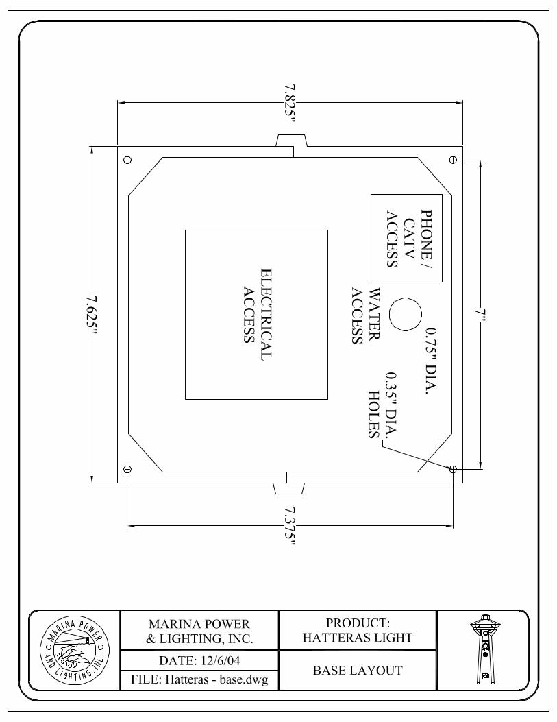
*We strongly recommend that a qualified electrical contractor install this unit. Installation Procedures: 1. Securing the Base and Mounting the Pedestal: (Always use stainless steel mounting hardware and a stainless steel washer between the bolt head and the mounting feet.) See the attached dimensional drawing of the base of the Hatteras Light. Suggested locations for the power supply as well as water, phone and cable TV utilities are identified. We recommend that you prepare the mounting of the base as follows: (Refer to mounting base diagram).
a. On Concrete Docks: At each corner, utilize four 1/4” compression bolts or threaded rod set in the concrete on 7” x 7 3/8” centers (see base layout drawing) for through-hole mounting of the Hatteras Light base.
b. On Wood Docks: At each corner, utilize four 1/4” bolts or lag screws on 7 3/8” center for through-hole mounting of the Hatteras Light base. Always use stainless bolts and washers to prevent damage while mounting the base. c. On Both Concrete and Wood Docks: The mounting surface must be flat and level. If cupped deck boards or an irregular concrete surface are under the base mount feet, stainless washers should be used to shim the base level before the tightening the mounting bolts or screws.
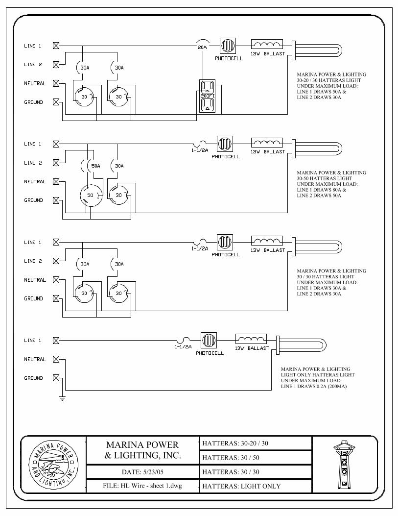
2. Connecting Power Supply to the Pedestal Bus Bars: While the top section of the unit is off, remove the plastic plate cover that is inside the top of the pedestal shaft. This will expose the bus bars in the top “neck” of the pedestal so that the installer can connect the power line to the bus bars 1/4” studs. The bus bar is identified L1, L2, N, Ground, make sure that the supply lines are connected to the proper bus lug. 3. Water, Phone/Cable TV Access: The water faucet is mounted on a panel that is attached to the pedestal with four screws. The phone/cable TV base and cover are also mounted to the pedestal with four screws. Remove the water or phone/cable TV panel to access the backside of the utility for connection. *Note: Water installation can be simplified by attaching a flexible hose from your waterline to the back of the faucet. 4. Installing the 13-Watt Fluorescent Light: The Hatteras Light pedestal is shipped with the 13-Watt bulb out of the socket to prevent breakage during shipment, and it is in a box taped inside of the top section of the pedestal. To access the bulb and socket, remove the four screws that fasten the lens to the housing and lift the top off. Remove the bulb from the box and snap it into the socket in the top. Discard the box. Put the top section of the pedestal back in position and replace the four screws into the bottom of the lens, making sure to press down on the top to compress the gasket at the bottom of the lens. Replace the bulb about every three years, or if the bulb fails to illuminate by following the same easy procedures described above.


# Part # Part1 Top - Only 28 Bulb
2A Amber Lens 29 1/2" Silcock2B Amber Lens - 3 Piece 30 Wiring (per foot)3 Counter 31 Stainless Steel Screws4 External Cover 32 Light Fuse
5A Door 33 Fuse Holder5B Door - Newport 34 Touch-up Paint Kit5C Door - Stainless Steel 35 Aluminum Face Plate6 100A Breaker Cover 36 Buss Bar Assembly7 100A Receptacle 37 Main Housing - Complete8 Hose & Cable Brackets 38 Stainless Steel Mouting Stand9 Main Housing - Complete 38 Aluminum Mounting Stand
9B Stainless Steel Door 39A Phone Shield10 Aluminum Hinge 39B Phone/Cable Conduit11 Hose Adapter 40A Conduit Male Adapter
11A Water Assembly - Complete 40B Male Coupling12 Water Mounting Plate 41 Newport Mounting Brackets
13A Pedestal Base w/ Buss Bars 42 Pedestal Main Housing13B Pedestal Base w/o Buss Bars 43 Mounting Feet14 Photocell 44 Red Strobe Light15 Ballast 45 Firehouse Top w/ Strobe Light16 Socket 46 Clear Door17 Meter 47 Life Ring18 Face Plate - Amber Lexan 48 Blank Access Panel19 Receptacle 49 Door / Life Ring Trigger20 Breaker Plate - Noryl Molded 50 Firehouse Buss Bar21 Breaker 51 Clear Door Hasp22 Terminal Barrier Isolators 52 Life Ring Bracket
23A Copper Buss Bar 53 Fire Extinguisher23B Copper Buss Bar 54 RV Phone & Cable TV Assembly24 Wire Terminations 55 Power Tower Light Switch25 3/4" Ball Valve 56 Stainless Steel Access Panel26 Backflow Preventer27 Phone/Cable TV Assembly
PARTS LISTS


Marina Power & Lighting, Inc. Toll Free: 800-723-8009 149 Warwick Court Phone: (757) 258-8800 Williamsburg, VA 23185 Fax: (757) 258-8805
ADDENDUM 1
Operation and Maintenance for Marina Power & Lighting Units Marina Power and Lighting produces units that are designed to withstand the harsh marine exterior environment. Very little maintenance is required to keep the units looking new for many years and to keep the warranty effective. I. Exterior Maintenance:
1.) To remove of dirt, grime, and bird droppings, use a mild solution of Dawn dishwashing detergent at approximately one teaspoon per gallon of warm water. 2.) To remove spider webs and droppings, follow step one above. After step one has been completed, follow up with a water based insect spray to kill the spiders around the base of the unit and in the receptacle area. DO NOT use a petroleum based insect spray. 3.) DO NOT use any solvent or corrosion inhibiting products on any part of the unit. This can cause serious stress cracking of the engineered resins.
II. Interior Maintenance:
1.) Before attempting the following maintenance procedures, turn off the power to the unit at the power supply panel (note the breakers on the unit DO NOT turn the unit power supply off and the buss bars will be energized.
A.) Exposing the Bus Bar Assembly: • Lighthouse & Powerhouse: Annually, the four screws holding the top of
the unit to the base should be removed and the unit should be tilted over to expose the buss bar area.
• Lighthouse SS: Annually, remove the access panel (14 screws) to expose the bus bars.
• Hatteras Light & Park Light: Annually, remove the light assembly (4 screws at base of light) and the plastic barrier to expose the bus bars.
• Newport Harbor Mate & Camp Mate: Annually, remove the light assembly at the bottom of the unit to expose the bus bars.
B.) Maintenance of Bus Bar Assembly: • On all units, the bus bars should be visually examined for excessive heating.
If potentially faulty or loose joints are found, they should be tightened or replaced.
C.) If Mechanical Lugs are Used Instead of the Stud-Lug Bus Assembly: • In the cases where mechanical lugs instead of the stud-lug bus assembly are
used, it is very important that they be examined closely. Most mechanical lugs are made of aluminum and are very susceptible to galvanic corrosion. If the set screw cannot be tightened, replace the lug. If there appears to be corrosion around the copper to aluminum connection, remove the copper wire and clean the wire, coat the wire with an anti-corrosion grease, and re-tighten the assembly.
2.) The receptacles and breakers should be examined annually, and if any sign of heating is evident, the receptacles or breakers should be replaced.
3.) DO NOT spray any solvents on the electrical components. Solvents will cause stress cracking of the polymeric materials.

III. Lighting Assembly: 1.) To test the lighting assembly, the photocell should be covered with a piece of
black tape and in about 2-3 minutes the light should illuminate. If this does not occur, the following items should be checked: photocell, bulb, and ballast.
IV. Winterizing: 1.) The water system should be purged with air and each ball valve should be
opened and closed after the system has been drained. This will remove the slug of water that remains in the ball. No other winterizing functions are required.
V. Operation: 1.) Insert the proper end of the shore power cord into the boat’s power inlet
connection, twist the plug to lock, then tighten the locking plug retainer by twisting the large nut until the unit is tight to the boat.
2.) With the breakers off, insert the shore power cord into the receptacle and twist the plug clockwise until the plug locks into the receptacle.
3.) With both connections secured, turn on the breaker. The power indicator on the boat should indicate a successful attachment of the plug and the receptacle.
6-2-05

3
Supplementary To Selling Policy 25-000 Dated 2-20-06 Limited Lifetime Warranty – Pedestals
Eaton Corporation warrants to the end user, the customer (you), that the utility pedestal, polycarbonate casing, and lens will be free from defects in materials and workmanship for the life of the product. If breakage occurs during this period the broken part shall be replaced at no charge. There is a full 2-year warranty on all receptacles and breakers for defects in material and workmanship in normal use. The limited warranty covers only those defects that arise in the normal use of the product. This limited warranty does not apply to any product that has been damaged, altered, subjected to abuse or misuse, or acts of nature. Light bulbs, photocells, and ballasts transformers are warranted for one year against manufacturer defects in material and workmanship. Meters are warranted for the life of the product and will be exchanged for a new or repaired meter during this period. Voltage surges above 140 volts/line and reverse polarity failure are not covered and will be repaired minimal charge plus shipping. Eaton Corporation will not accept back charges for any work performed by an outside contractor that has not been previously authorized in writing by Eaton Corporation.