HARVIA SAUNA · Remove the glass element from the hinges (patterned glass only). 2. Unfasten the...
16
16042015 HARVIA SAUNA Instructions for Planning and Installation
Transcript of HARVIA SAUNA · Remove the glass element from the hinges (patterned glass only). 2. Unfasten the...
16042015
HARVIA SAUNA
Instructions for Planning and Installation
2
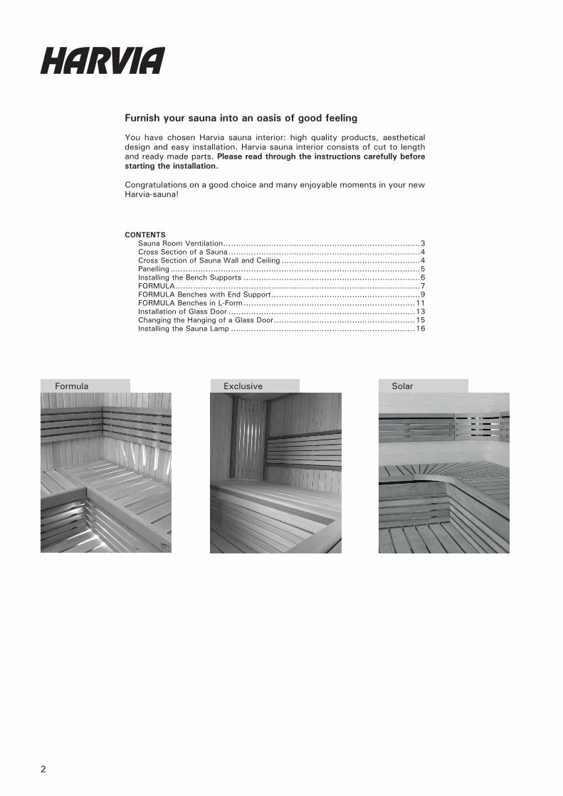
Furnish your sauna into an oasis of good feeling
You have chosen Harvia sauna interior: high quality products, aesthetical design and easy installation. Harvia sauna interior consists of cut to length and ready made parts. Please read through the instructions carefully before starting the installation.
Congratulations on a good choice and many enjoyable moments in your new Harvia-sauna!
CONTENTSSauna Room Ventilation ..............................................................................3Cross Section of a Sauna ............................................................................4Cross Section of Sauna Wall and Ceiling .......................................................4Panelling ...................................................................................................5Installing the Bench Supports ......................................................................6FORMULA .................................................................................................7FORMULA Benches with End Support ...........................................................9FORMULA Benches in L-Form ....................................................................11Installation of Glass Door ..........................................................................13Changing the Hanging of a Glass Door ........................................................15Installing the Sauna Lamp .........................................................................16
Formula SolarExclusive
3
SAUNA ROOM VENTILATION
D
B
min
. 500 m
m
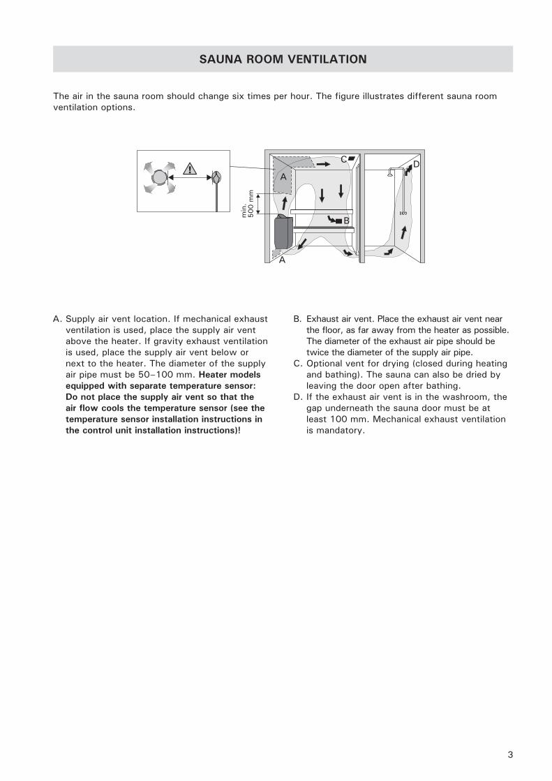
The air in the sauna room should change six times per hour. The figure illustrates different sauna room ventilation options.
A. Supply air vent location. If mechanical exhaust ventilation is used, place the supply air vent above the heater. If gravity exhaust ventilation is used, place the supply air vent below or next to the heater. The diameter of the supply air pipe must be 50–100 mm. Heater models equipped with separate temperature sensor: Do not place the supply air vent so that the air flow cools the temperature sensor (see the temperature sensor installation instructions in the control unit installation instructions)!
B. Exhaust air vent. Place the exhaust air vent near the floor, as far away from the heater as possible. The diameter of the exhaust air pipe should be twice the diameter of the supply air pipe.
C. Optional vent for drying (closed during heating and bathing). The sauna can also be dried by leaving the door open after bathing.
D. If the exhaust air vent is in the washroom, the gap underneath the sauna door must be at least 100 mm. Mechanical exhaust ventilation is mandatory.
4
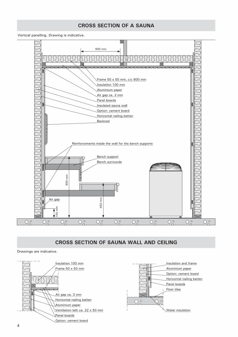
CROSS SECTION OF SAUNA WALL AND CEILING
CROSS SECTION OF A SAUNA
Vertical panelling. Drawing is indicative.
Frame 50 x 50 mm, c/c 600 mm
Insulation 100 mm
Aluminium paper
Air gap ca. 3 mm
Panel boards
Insulated sauna wall
Option: cement board
Horizontal nailing batten
Backrest
Reinforcements inside the wall for the bench supports
Air gap
900 m
m
450 m
m
150 m
m
Bench support
Bench surrounds
600 mm
Insulation 100 mm
Frame 50 x 50 mm
Air gap ca. 3 mm
Horizontal nailing batten
Aluminium paper
Ventilation lath ca. 22 x 50 mm
Panel boards
Option: cement board
Insulation and frame
Aluminium paper
Option: cement board
Horizontal nailing batten
Panel boards
Floor tiles
Water insulation
Drawings are indicative.
5
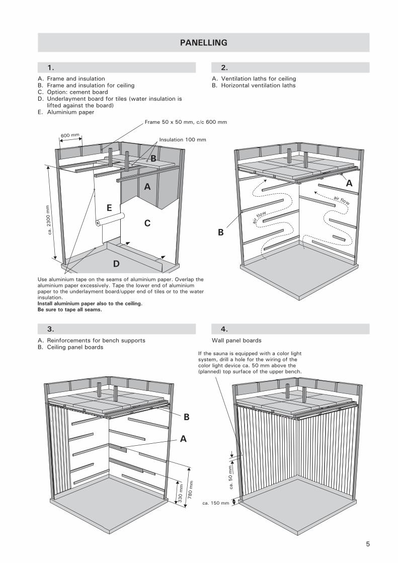
PANELLING
A. Frame and insulationB. Frame and insulation for ceiling C. Option: cement boardD. Underlayment board for tiles (water insulation is
lifted against the board)E. Aluminium paper
A. Ventilation laths for ceilingB. Horizontal ventilation laths
1. 2.
air f
low
air flow
600 mm
ca. 2300 m
m
780 m
m
ca. 150 mm
ca.
50 m
m
Frame 50 x 50 mm, c/c 600 mm
Insulation 100 mm
A. Reinforcements for bench supportsB. Ceiling panel boards
Wall panel boards
A
3. 4.
330 m
m
A
B
D
E
Use aluminium tape on the seams of aluminium paper. Overlap the aluminium paper excessively. Tape the lower end of aluminium paper to the underlayment board/upper end of tiles or to the water insulation. Install aluminium paper also to the ceiling. Be sure to tape all seams.
If the sauna is equipped with a color light system, drill a hole for the wiring of the color light device ca. 50 mm above the (planned) top surface of the upper bench.
B
A
B
C
6
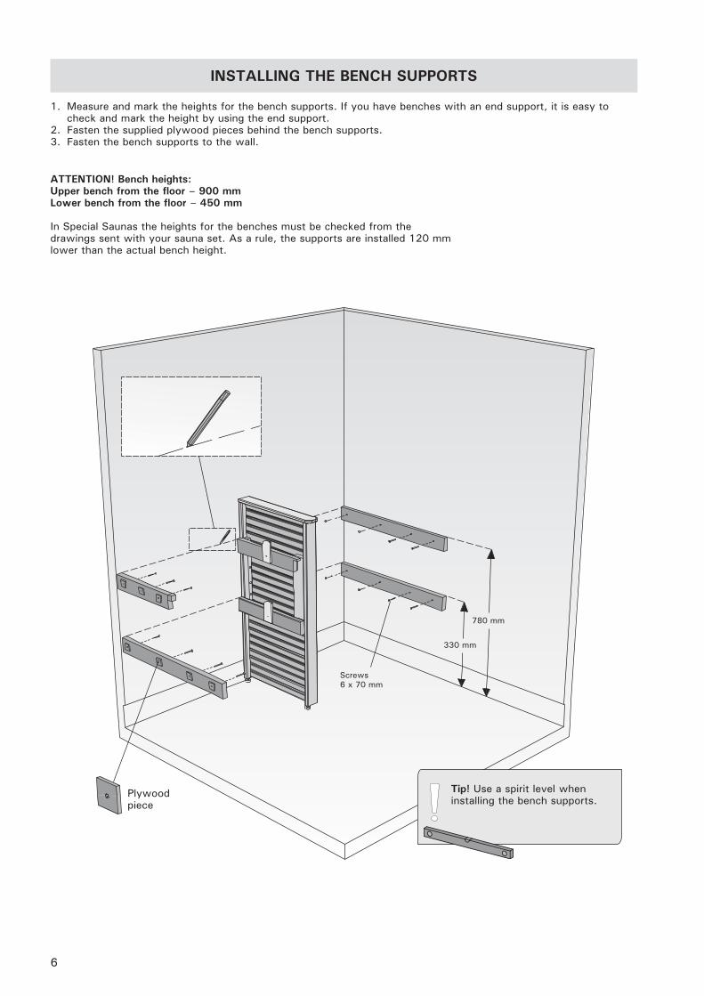
INSTALLING THE BENCH SUPPORTS
ATTENTION! Bench heights:Upper bench from the floor – 900 mmLower bench from the floor – 450 mm
In Special Saunas the heights for the benches must be checked from the drawings sent with your sauna set. As a rule, the supports are installed 120 mm lower than the actual bench height.
780 mm
330 mm
1. Measure and mark the heights for the bench supports. If you have benches with an end support, it is easy to check and mark the height by using the end support.
2. Fasten the supplied plywood pieces behind the bench supports.3. Fasten the bench supports to the wall.
Tip! Use a spirit level when installing the bench supports.
Plywood piece
Screws6 x 70 mm
7
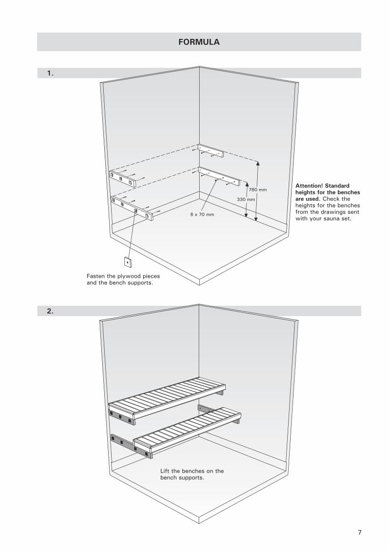
1.
780 mm
330 mm
Fasten the plywood pieces and the bench supports.
FORMULA
2.
Lift the benches on the bench supports.
Attention! Standard heights for the benches are used. Check the heights for the benches from the drawings sent with your sauna set.
6 x 70 mm
8
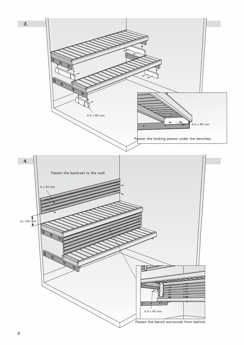
4.
3.
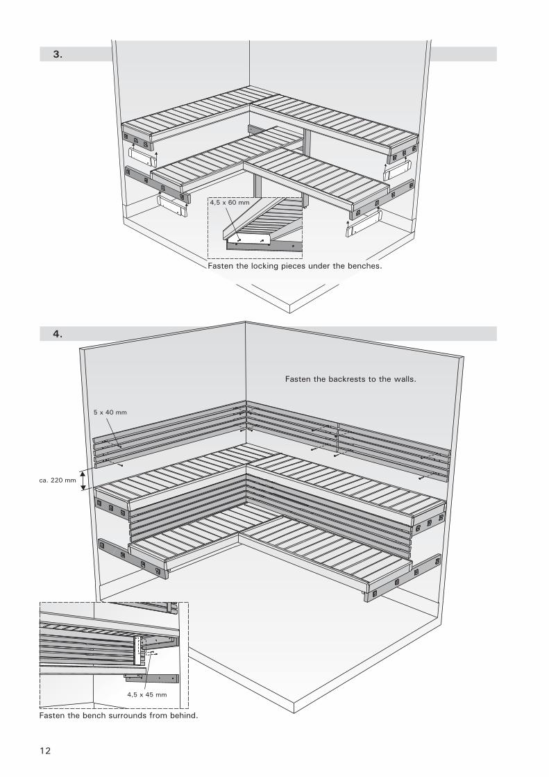
Fasten the locking pieces under the benches.
4,5 x 60 mm
4,5 x 60 mm
Fasten the backrest to the wall.
ca. 220 mm
Fasten the bench surrounds from behind.
5 x 40 mm
4,5 x 45 mm
9
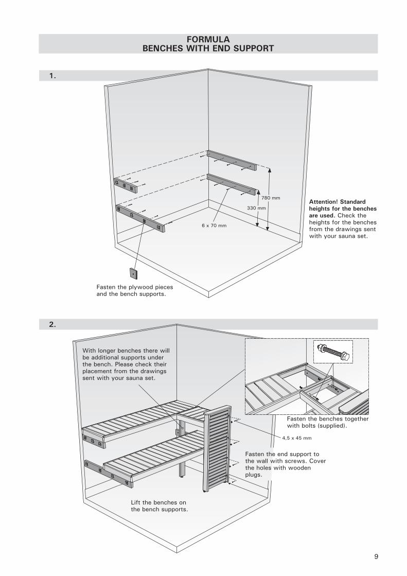
FORMULA BENCHES WITH END SUPPORT
1.
2.
Fasten the plywood pieces and the bench supports.
780 mm
330 mm
Fasten the end support to the wall with screws. Cover the holes with wooden plugs.
Fasten the benches together with bolts (supplied).
With longer benches there will be additional supports under the bench. Please check their placement from the drawings sent with your sauna set.
6 x 70 mm
Attention! Standard heights for the benches are used. Check the heights for the benches from the drawings sent with your sauna set.
4,5 x 45 mm
Lift the benches on the bench supports.
10
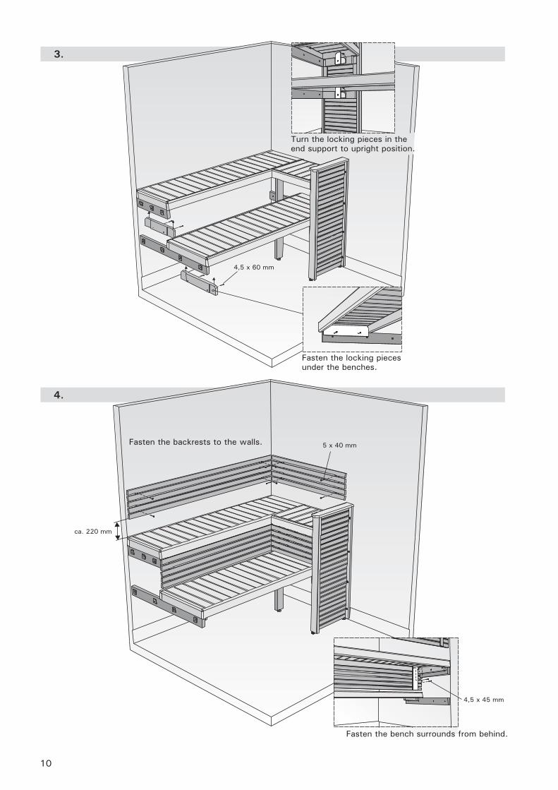
4.
3.
Fasten the backrests to the walls.
Fasten the bench surrounds from behind.
Turn the locking pieces in the end support to upright position.
Fasten the locking pieces under the benches.
ca. 220 mm
4,5 x 60 mm
5 x 40 mm
4,5 x 45 mm
11
Fasten the bench surrounds from behind.
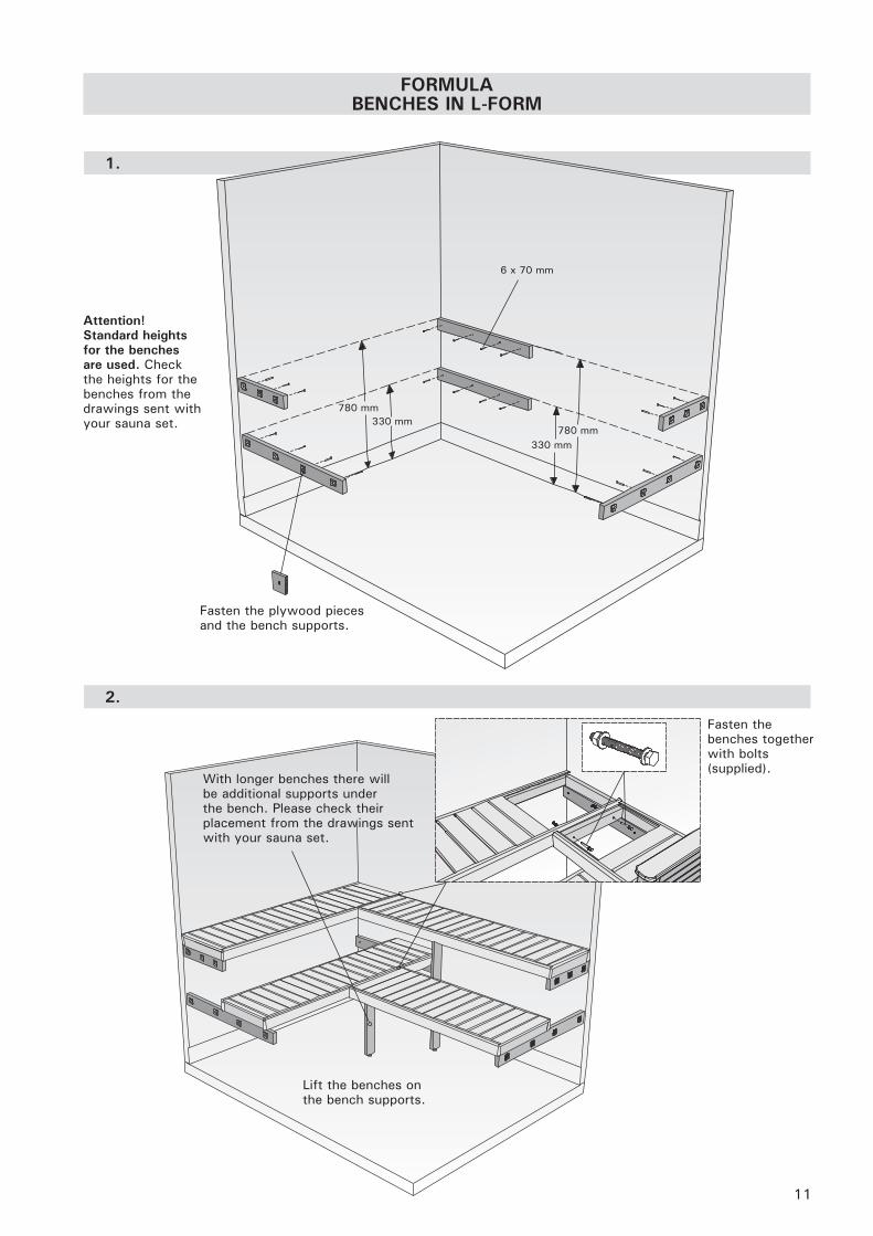
FORMULA BENCHES IN L-FORM
1.
2.
780 mm330 mm
780 mm330 mm
Fasten the benches together with bolts (supplied).
6 x 70 mm
Lift the benches on the bench supports.
Fasten the plywood pieces and the bench supports.
With longer benches there will be additional supports under the bench. Please check their placement from the drawings sent with your sauna set.
Attention! Standard heights for the benches are used. Check the heights for the benches from the drawings sent with your sauna set.
12
4.
3.
Fasten the locking pieces under the benches.
Fasten the bench surrounds from behind.
ca. 220 mm
Fasten the backrests to the walls.
5 x 40 mm
4,5 x 45 mm
4,5 x 60 mm
13
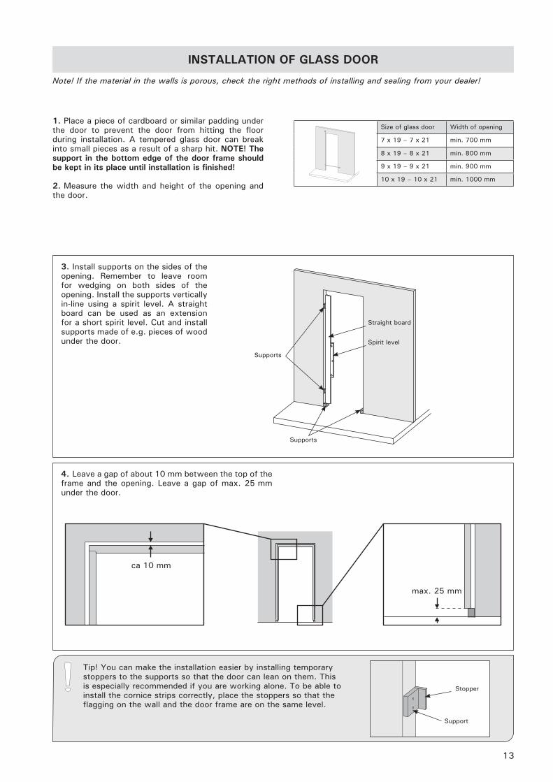
max. 25 mm
ca 10 mm
Note! If the material in the walls is porous, check the right methods of installing and sealing from your dealer!
1. Place a piece of cardboard or similar padding under the door to prevent the door from hitting the floor during installation. A tempered glass door can break into small pieces as a result of a sharp hit. NOTE! The support in the bottom edge of the door frame should be kept in its place until installation is finished!
2. Measure the width and height of the opening and the door.
INSTALLATION OF GLASS DOOR
Size of glass door Width of opening
7 x 19 – 7 x 21 min. 700 mm
8 x 19 – 8 x 21 min. 800 mm
9 x 19 – 9 x 21 min. 900 mm
10 x 19 – 10 x 21 min. 1000 mm
Straight board
Supports
Spirit level
Supports
3. Install supports on the sides of the opening. Remember to leave room for wedging on both sides of the opening. Install the supports vertically in-line using a spirit level. A straight board can be used as an extension for a short spirit level. Cut and install supports made of e.g. pieces of wood under the door.
Tip! You can make the installation easier by installing temporary stoppers to the supports so that the door can lean on them. This is especially recommended if you are working alone. To be able to install the cornice strips correctly, place the stoppers so that the flagging on the wall and the door frame are on the same level.
Support
Stopper
4. Leave a gap of about 10 mm between the top of the frame and the opening. Leave a gap of max. 25 mm under the door.
14
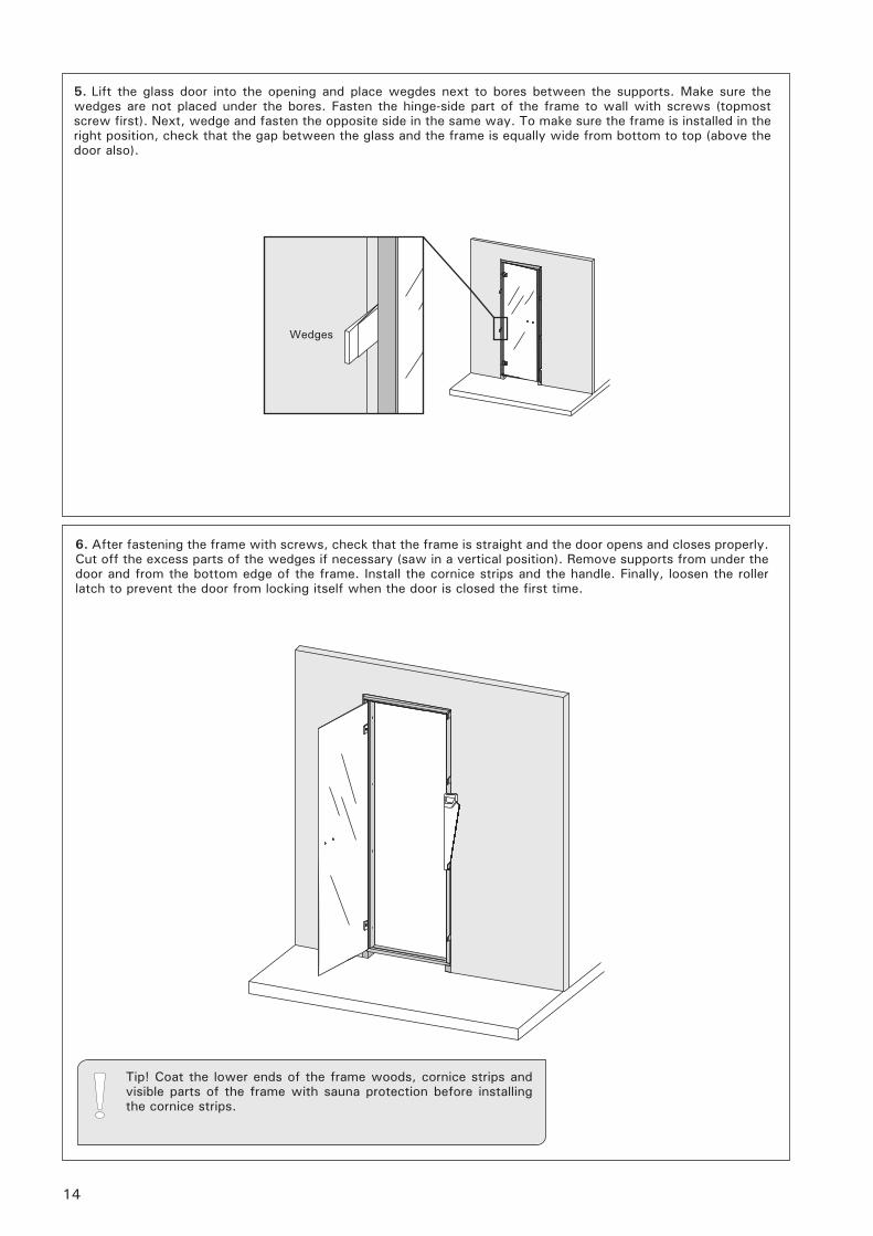
5. Lift the glass door into the opening and place wegdes next to bores between the supports. Make sure the wedges are not placed under the bores. Fasten the hinge-side part of the frame to wall with screws (topmost screw first). Next, wedge and fasten the opposite side in the same way. To make sure the frame is installed in the right position, check that the gap between the glass and the frame is equally wide from bottom to top (above the door also).
6. After fastening the frame with screws, check that the frame is straight and the door opens and closes properly. Cut off the excess parts of the wedges if necessary (saw in a vertical position). Remove supports from under the door and from the bottom edge of the frame. Install the cornice strips and the handle. Finally, loosen the roller latch to prevent the door from locking itself when the door is closed the first time.
Wedges
Tip! Coat the lower ends of the frame woods, cornice strips and visible parts of the frame with sauna protection before installing the cornice strips.
15
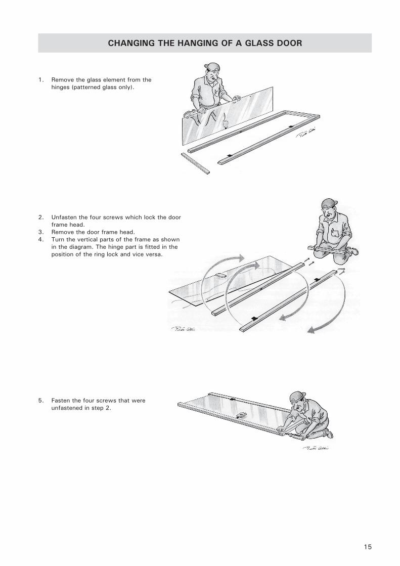
5. Fasten the four screws that were unfastened in step 2.
1. Remove the glass element from the hinges (patterned glass only).
2. Unfasten the four screws which lock the door frame head.
3. Remove the door frame head.4. Turn the vertical parts of the frame as shown
in the diagram. The hinge part is fitted in the position of the ring lock and vice versa.
CHANGING THE HANGING OF A GLASS DOOR
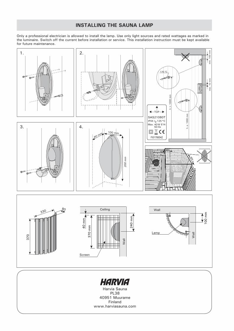
INSTALLING THE SAUNA LAMP
Only a professional electrician is allowed to install the lamp. Use only light sources and rated wattages as marked in the luminaire. Switch off the current before installation or service. This installation instruction must be kept available for future maintenance.
370
80330
370 m
m 240 m
m
40 m
m
100 m
mCeiling
Screen
Lamp
Wall
Wal
l
Wal
l
1. 2.
3. 4.200 m
m
90 mm
100 mm
TOP
IP44 ta 125 °CMax. 40 W E14
50 Hz
SAS21060T
170 0C
h >
1000 m
m
h ≤
1000 m
m
min
. 100 m
mm
in.
10 m
m