Harvard PCM (Plate Cleaning Machine) Robert J. Simcoe (Bob) Ed Los Jonathan Grindlay.
21
Harvard PCM (Plate Cleaning Machine) Robert J. Simcoe (Bob) Ed Los Jonathan Grindlay
-
Upload
berniece-ramsey -
Category
Documents
-
view
217 -
download
1
Transcript of Harvard PCM (Plate Cleaning Machine) Robert J. Simcoe (Bob) Ed Los Jonathan Grindlay.

Harvard PCM(Plate Cleaning Machine)
Robert J. Simcoe (Bob)
Ed Los
Jonathan Grindlay

Motivation
• 500,000 plates
• Http://dasch.rc.fas.harvard.edu/project.php
• ~60,000+ plates scanned during development phase
• Plate cleaning 4-5 x longer than digitizing
• Want to match digitizer rate.
• Hand cleaning too much labor cost to support

PCM overview
• Elements of the design– Transport bed– Fixture to capture, protect, and move the plate– 3 brushes to clean the plate– Air knife to blow dry the plate– Means to load/unload, the plate into the
fixture.– Means to move the fixture with the plate

Overview of PCM components
Anisotropic Bed
Side Tracks
Loading area
Loading drive
Stationary loading
Plate
AC and DC Power
Cleaning Brushes
Air knife
Rotating Table
Plate guides
Control computer

Transport bedAluminum base plate
Roller bearing with O-rings (EDPM rubber)
Stainless steel rod
Screw holes for Delrin piece to clamp rod
Opening for various stations

Modular plate for bedPlate CNC machined in modular sections that could butt together (2 bed sections)
Bed section and work stationOpenings flexible
Total bed is 15 ½ bed sections and 12 open areas
Full bed is 564 roller bearings with 2820 EDPM rubber O-rings
Tied together here with long outer rails and the center rail

Plate fixture without rubber
Plenum with air holes
Delrin angles
Supports for air cylinders to lift fixture

Plate fixture with silicone rubber
Black silicone rubber that is very soft to grab and seal the plate edge
Grey silicone rubber that is harder and protects emulsion

Top side of fixture
Roller bearings to support plate on top of side rails and prevent lifting by brushes
Drive chain engagers
Magnetic to trip sensors along the track to verify position.
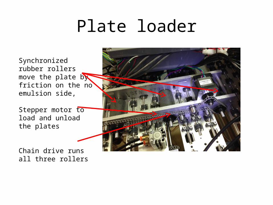
Plate loader
Synchronized rubber rollers move the plate by friction on the no emulsion side,
Stepper motor to load and unload the plates
Chain drive runs all three rollers

Capture station
SynchronizedPlate driverollers
Fixture drive ladder chain
Air cylinder lifters
Slots in side rails where fixture rollers can go thru
Plate stops
Air cylinder lifters
Hall sensor to identify home position
Reflective sensor below

Custom rotary brush
The brush is made from a stainless steel rod that has a spiral groove that holds the bristle with a steel wire
The length, ends, and bristle type and diameter are all custom specified
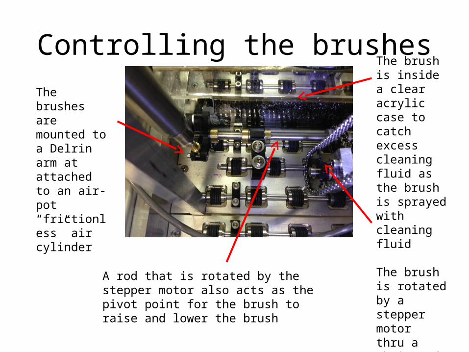
Controlling the brushes
The brushes are mounted to a Delrin arm at attached to an air-pot “frictionless” air cylinder
The brush is inside a clear acrylic case to catch excess cleaning fluid as the brush is sprayed with cleaning fluid
The brush is rotated by a stepper motor thru a chain and gear drive system
A rod that is rotated by the stepper motor also acts as the pivot point for the brush to raise and lower the brush
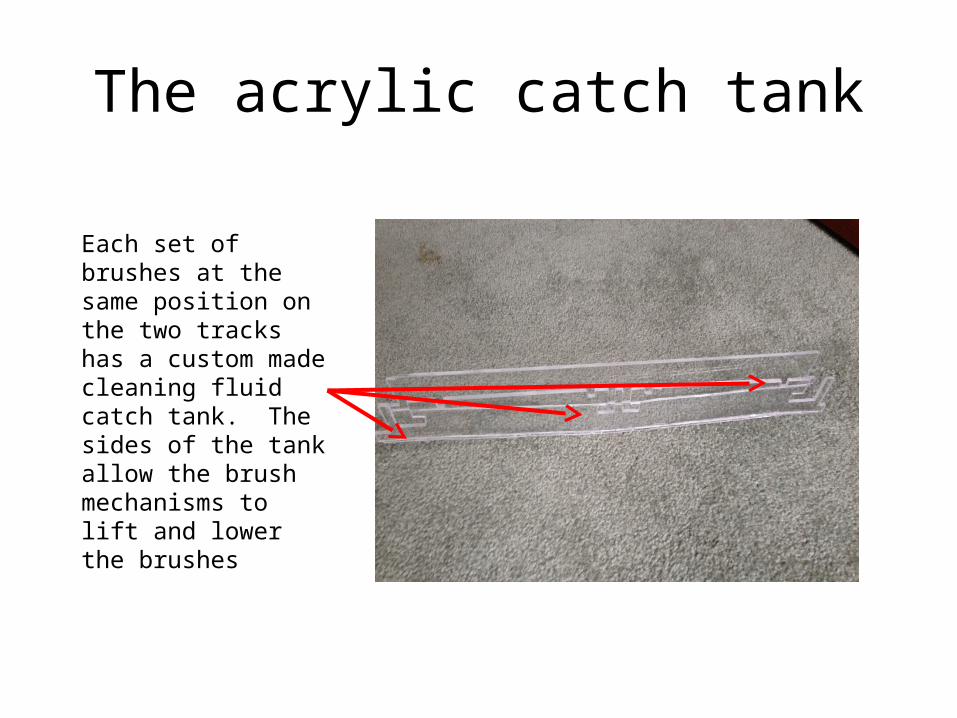
The acrylic catch tank
Each set of brushes at the same position on the two tracks has a custom made cleaning fluid catch tank. The sides of the tank allow the brush mechanisms to lift and lower the brushes

The six brushes (three for each side)
The acrylic catch tubs are shared across two tracks
The brushes are wet by brass tubes with a series of .015 holes that spray up against a lowered brush

The three Brush cleaning stations
The three bushes for each track are raised against the plates and rotated to scrub the plates clean.

Cleaning fluid pumpsThe cleaning fluid pumps are individually controlled one for each brush
Fluid moves in a series of tanks from the brush closest to the air knife to the one furthest back
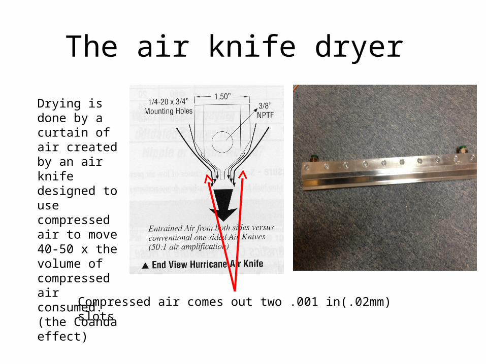
The air knife dryer
Drying is done by a curtain of air created by an air knife designed to use compressed air to move 40-50 x the volume of compressed air consumed. (the Coanda effect)
Compressed air comes out two .001 in(.02mm) slots

Electronic control boards
The pololu computer board
The pololu LCD display
The pololu stepper motor driver
The custom designed I/O expander board

The custom I/O expander board
5 motor drivers
Output connectors
Three I2C I/O expander chips
3 open collector (12v) driver chips
I2C input pins
Input connectors 12V and 5 volt supplies

Cleaning cycle