HART is a registered trademark of the HART … for continuous non-contact level measurement in...
12
Technical Information TI 246F/00/en Application The Prosonic T is a compact ultrasonic transmitter for continuous non-contact level measurement in liquids and in coarse-grained or pelleted solids. The Prosonic T series consists of three transmitters, which can be equipped with one of several electronic modules, with graduated measuring ranges from 0.25 m (0.8 ft) upwards. • FMU 130, 230 in coarse-grained solids (grain size from 4 mm/0.16 in) up to 2 m/6.6 ft in liquids up to 5 m/16.4 ft • FMU 131, 231 in coarse-grained solids (grain size from 4 mm/0.16 in) up to 3.5 m/11.5 ft in liquids up to 8 m/26.2 ft • FMU 232 in coarse-grained solids (grain size from 4 mm/0.16 in) up to 7 m/23 ft in liquids up to 15 m/49.2 ft All transmitters are equipped with an integrated temperature sensor for time-of-flight compensation. Features and Benefits Fits exactly to the process • Threaded connections from G 1 1 / 2 or 1 1 / 2 NPT or flange 4" or DN 100 • Fully rotatable housing • LEDs visible through housing cover allow quick monitoring of operational status Electronics versions • FMU 130, 131: 2-wire loop-powered general approval for "EEx ia" • FMU 230, 231: 2-wire loop-powered or 4-wire including mains power supply • FMU 232: 4-wire, optional approval for dust Ex Zone 10 including mains power supply Intelligent operation and evaluation • Simple local push-button operation, with optional display • Smart INTENSOR or HART protocols for remote operation • Digital communication with PROFIBUS-PA HART is a registered trademark of the HART Communication Foundation Ultrasonic Level Measurement prosonic T FMU 130, 131 prosonic T FMU 230, 231, 232 Compact transmitter for continuous, non-contact level measurement Available as a Smart transmitter or for connection to process control systems Hauser + Endress Nothing beats know-how
Transcript of HART is a registered trademark of the HART … for continuous non-contact level measurement in...

TechnicalInformationTI 246F/00/en
Application The Prosonic T is a compact ultrasonictransmitter for continuous non-contactlevel measurement in liquids and incoarse-grained or pelleted solids. TheProsonic T series consists of threetransmitters, which can be equippedwith one of several electronic modules,with graduated measuring ranges from0.25 m (0.8 ft) upwards.• FMU 130, 230
in coarse-grained solids (grain sizefrom 4 mm/0.16 in) up to 2 m/6.6 ftin liquids up to 5 m/16.4 ft
• FMU 131, 231in coarse-grained solids (grain sizefrom 4 mm/0.16 in) up to 3.5 m/11.5 ftin liquids up to 8 m/26.2 ft
• FMU 232in coarse-grained solids (grain sizefrom 4 mm/0.16 in) up to 7 m/23 ftin liquids up to 15 m/49.2 ft
All transmitters are equipped with anintegrated temperature sensor fortime-of-flight compensation.
Features and BenefitsFits exactly to the process• Threaded connections from G 11/2 or
11/2 NPT or flange 4" or DN 100• Fully rotatable housing• LEDs visible through housing cover
allow quick monitoring of operationalstatus
Electronics versions• FMU 130, 131: 2-wire loop-powered
general approval for "EEx ia" • FMU 230, 231: 2-wire loop-powered or
4-wire including mains power supply• FMU 232: 4-wire, optional approval for
dust Ex Zone 10 including mainspower supply
Intelligent operation and evaluation• Simple local push-button operation,
with optional display• Smart INTENSOR or HART protocols
for remote operation• Digital communication with
PROFIBUS-PAHART is a registered trademark of the HART Communication Foundation
Ultrasonic Level Measurementprosonic T FMU 130, 131prosonic T FMU 230, 231, 232
Compact transmitter for continuous, non-contact level measurement Available as a Smart transmitter orfor connection to process control systems
Hauser+EndressNothing beats know-how

Measuring System The Prosonic T compact ultrasonictransmitter is a complete measuringpoint within itself. The simplest versionallows access to all functions requiredfor basic operation. Calibration can becarried out using the four pushbuttons–, +, V, H on the instrument without theneed for other equipment. With a plug-in display, the completeEndress+Hauser user matrix can beaccessed.
The basic functionality may beenhanced by other optional operatingpossibilities or integration into a processcontrol system, e.g. via: • 2-wire loop-powered 4…20 mA
(Smart) with INTENSOR or HARTprotocol or for connection toPROFIBUS-PA bus systems
• 4-wire, with separate power supply,4…20 mA (Smart) with HART protocol
2-wire 4…20 mA Loop-Powered Applications in e.g. Storage Vessels
FMU 130, FMU 131: Certificate EEx iaFMU 230, FMU 231: Standard
4-wire, 4…20 mASeparate Power SupplyApplications with Rapid Changes inLevel, e.g. Process Vessels
FMU 230, FMU 231: Standard FMU 232: Optional Dust Ex Zone 10
FMX 770
IO
IO
1
2
5
4
3
FXN 671
mA1+
PLC
FXN 671
FMX 770
PROFIBUS-PA
Commu-box
Isolator
PROFIBUS-DP
PLC
Rackbus
Rackbus
4…20 mA
4…20 mA
4…20 mA
Ex isolator PLC
Commuwin II
HART
HART
INTENSOR
➀ Power supply via the transmitter power pack e.g. PLC, with FMU 130, 131 connection via the Ex isolator (Zener barrier: <30 VDC output voltage, <200 mA, <1 W): operation via handheld terminal (protocol: INTENSOR, HART)
➁ FXN 671: operation via Rackbus or handheld terminal (protocol: INTENSOR)➂ Silometer FMX 770: operation via Commutec transmitter (protocol: INTENSOR)➃ Connection to PROFIBUS-PA bus for up to 10 transmitters, operated by a PC ➄ Commubox: interface to a PC for Smart transmitters, operated by a PC (protocol: INTENSOR, HART)
IO
1Commu-box
Operation via HART or Commuwin II
PLC
➀ Operation via HART protocol: point-to-point using handheld terminal or PC (Commubox)
2

Operation Prosonic T compact transmitters offeroperation tailored to all level applications:• Local calibration or matrix operation
by simply pressing buttons• Smart – remote operation and display
via the handheld terminal • Comprehensive operating and display
software for personal computer• Calibration in the control room via a
Silometer FMX 770 or FXN 671.
Matrix OperationProsonic T can be operated by usingthe keyboard and display, a handheldterminal, a Silometer transmitter(FMX 770, FXN 671) or via a processbus. The identical operating matriceensure that procedures are uniform andclear.
Operation via DisplayParameters are entered and valuesdisplayed by using the four pushbuttons–, +, V, H on the front panel of the device.The optional display provides access tothe Endress+Hauser operating matrix andto a wide selection of additional functions.• The following application parameters
are available:− Liquid− Rapid changes in levels of liquids− Measurement when mounted in the
dome cover− Coarse-grained solids− Conveyor belt
• Automatic suppression of three fixedtarget echoes
• Linearisation (11 points)• First echo detection (double echo)• Automatic suppression of stirrer
echoes
Operation Without a DisplayThe basic functions of the Prosonic Tcan be set by using just the fourpushbuttons –, +, V, H on the front panelof the instrument.• Empty and full calibration• Parameter protection by entry locking
V H
16602
Reset
Unlock parameters
Lock parameters
Full calibration
Empty calibration0 %: 4 mA
100 %: 20 mA
V V+ +– –H H
V+– H
V
H
!4 ...
4
+20 mA
5
-
+2
1
V H
+
1 2
H0V0V1V2V3V4
H1 H2 H3 H4V+– H
V+– H
Matrix operation with display
OR Calibration without display
Status indication and operating display also with housing cover closed
Local matrix operation via display Setting basic functions locally using four pushbuttons
3

PROFIBUS-PAThe PROFIBUS-PA is an open fieldbusstandard for connecting sensors andactuators, which may also be inexplosion hazardous areas, to one buscable. The two-wire sensors aresupplied with power over thePROFIBUS-PA and the processinformation of the sensor is digitallytransmitted.
The number of instruments operated atone bus segment:• up to 10 for EEx ia applications• up to 32 for non-Ex applications
Operation via Handheld TerminalWith a handheld terminal, the Prosonic Tcan be configured, values displayed andadditional functions activated fromanywhere on the 4…20 mA signal line.There are two versions:• Commulog VU 260 Z (INTENSOR)• Universel HART Communicator DXR 275
Operation with Commubox Commubox FXA 191 connectsintrinsically safe Smart transmitters withINTENSOR or HART protocols to theRS 232 C serial interface of a personalcomputer, allowing remote operation bythe Endress+Hauser Commuwin IIoperating program.
R
IO
Connecting the handheld terminalanywhere along the 4…20 mA cable ordirectly on the compact echo transmitter
Minimum total resistance 250 Ω
4…20 mA
OR
Connecting handheldterminals
+
Commubox4…20 mA
Commuwin II
Powerpack
Power supply
Min
imum
tota
l res
ista
nce
250
Ω
Connecting theCommubox
ENDRESS + HAUSER
Commuwin II PLC
Tanks with Prosonic T
Segment couplerFXN 623 A(non-Ex)FXN 623 C(EEx ia)PROFIBUS-PA
PROFIBUS-DP
A Prosonic T with thePROFIBUS-PA protocolallows:• local operation with
display• matrix operation with
a personal computerand the Commuwin IIoperating programrunning under MSWindows 3.11
4

Installation Mounting • Always mount the sensor such that the
distance between it and the maximumproduct level exceeds the blockingdistance. The lower edge of thetransmitter should, however, projectbelow the roof of the tank or silo.Exception: mounting in a nozzle.
• Never mount two Prosonic T in avessel because the instruments maynot function correctly.
• Do not mount the sensor in the centre ofthe vessel roof.
• Position the sensor at right angles tothe surface of the material.
• Do not measure through the fillingcurtain.
Blocking DistanceDue to the ringing time of the sensor,there is a zone immediately below it inwhich returning echoes cannot bedetected. This so-called blockingdistance determines the minimumdistance between the sensor and themaximum level in the tank or silo (seeTechnical Data for values).
Interference SuppressionInterference echoes coming frominternal fittings can be suppressed byusing the fixed target suppressionfunction. The signals are then no longerrecorded or used for further processing.The ultrasonic pulse leaves the sensoras a narrow beam which widens withincreasing distance from the device.Every object within this beam producesan interference echo which is receivedby the sensor.
Mounting on a NozzleIf the maximum level to be measuredfalls within the blocking distance, thetransmitter must be mounted on anozzle. • No build-up should form in the nozzle.• The recommend nozzle dimensions
are limits, within which the nozzle canvary. Check that the nozzle diameter islarge enough, but keep the nozzlelength to a minimum (see figure).
• The inner surface of the nozzle shouldbe as smooth as possible – no edgesor welding seams.
Other Types of Mounting• below left:
mounting with welded sleeve • below right:
mounting with counter nut
LL
D
D
Sensor FMU D mm (in) max. L mm (in)
130 / 230 50 (2) 150 (5.9)
130 / 230 80 (3.1) 240 (9.4)
130 / 230 100 (3.9) 380 (15)
131 / 231 80 (3.1) 240 (9.4)
131 / 231 100 (3.9) 380 (15)
232 100 (3.9) 300 (11.8)
Dimensions without DisplayDmin = 100 mm (3.9 in)Lmax = 150 mm (5.9 in)
Dimensions with Display
Maximumlevel
Blockingdistance
Violation ofthe blockingdistancemay lead toincorrectoperation.
5

Measuring Range The maximum measuring range of theProsonic T is limited by the conditions atthe measuring point and the reflectioncharacteristics of the product surface. Optimum conditions are achieved if:
• the surface of the liquid is calm andwithout foam,
• no large concentrations of vapour arepresent in the tank,
• the solid material is hard andcoarse-grained,
• no dust is present in the silo,• temperature layering in the tank or silo
is low.
Example for Calculating RangeCheck the factors affecting yourmeasurement in the table to the right.Add up their attenuation values (dB).
• Temperature difference in silo max. 40°C (104°F) 10 dB
• Low amount of filling curtain in detection area 5 dB
• Surface of liquid with strong turbulence 20 dB
Sum of attenuation values 35 dBRange below these factors thus approx. 5.8 m (19 in) with 2" sensor.
Effects Attenuation(dB)
Temperature layeringFor air temperature differencebetween sensor and productsurface up to 20°C (68°F)
up to 40°C (104°F)up to 80°C (176°F)
05…1010…20
Filling curtainOutside detection rangeSmall amount inside detection rangeLarge amount insidedetection range
0
5…10
10…20
DustNoneSmall amountLarge amount
055…10
Solids surfaceCoarse, hardSoft
2020…40
Liquid surface CalmHeavy wavesVery turbulent (e.g. agitators)
05…1010…20
FoamPlease consult Endress+Hauser
The diagram shows ideal echoattenuation curves.➀ Move the ideal curve downwards
corresponding to the sum of the attenuation values.
➁ The maximum range is indicated at theintersection where the ideal curve andthe interference level line meet.
101 2 4 5 6 7 8 93
60
120
0
20
40
80
100
1
2
35dB
Noise level line
1 m = 3.28 ft1 ft = 0.305 m
Echo attenuation FMU 130, 131, 230, 231 Example for determining range
10 20
20
40
60
80
100
02 4 6 8 12 14 16 18 22 24 26
Blocking distance for 11/2" sensor Blocking distance for 2" sensor
Range / m
Echo attenuation / dB
Normal interference level
Example:Range approx. 5.8 m
Ideal curve for 2" sensor
Ideal curve for 11/2" sensor
Range / m
Echo attenuation / dB
Blocking distance for 4" sensor
Ideal curve for 4" sensor
Normal interference level
Noise level line
Echo attenuation FMU 232
6

Electrical Connection ➀ FMU 130, 131, 230, 231• 2-wire »loop-powered«• Communication: INTENSOR or HART
➁ FMU 230, 231• 4-wire, including mains power supply
➂ FMU 232• 4-wire, including mains power supply
➃ FMU 130, 131 PROFIBUS-PA• 2-wire• Communication: PROFIBUS-PA• Current consumption:
FMU 130, 131, 230, 231: 12 mA ±1 mAFMU 232: 16 mA ±1 mA
• Please see also: TI 260F and BA 166F
CablingFor FMU 130, 131, 230, 231 instrumentswith communication use screenedcommercial 2-wire cable for signaltransmission or for FMU 230, 231, 2324-wire cable for signal transmission andpower. Under certain circumstances,the digital communication signal may beaffected if unscreened cable is used.
1000
U/V
FMU 230 / 231
FMU 130 /131
R/Ω
2012 18 24 30 36
750
Load diagram
!4+4
…
+
d4d2
–
20 mA–5
V
V
+
+
H
H
+
4…20 mA
FMX 770FXN 671
➀
!4I+4
20 mAI-5
V
V
+
+
H
H
+
L+L11
L-N2 3
+ –
L+/L1
L–/N
➁
18…36 VDC90…127 VAC180…250 VAC
4…20 mA
!4I+4
20 mAI-5
V
V
+
+
H
H
+
L+L11
L-N2 3
+ –
L+/L1
L–/N
18…36 VDC90…127 VAC180…250 VAC
➂
4…20 mA
!L+4
L-5
V
V
+
+
H
H
onadressoff
+ –
PROFIBUS PA
1 2 3 4 5 6 7 8
onaddressoff1 2 3 4 5 6 7 8
2 + 8 = 10
➃
Every instrument has a uniqueaddress.
off: Hardware address on: Software address
9…30 V
7
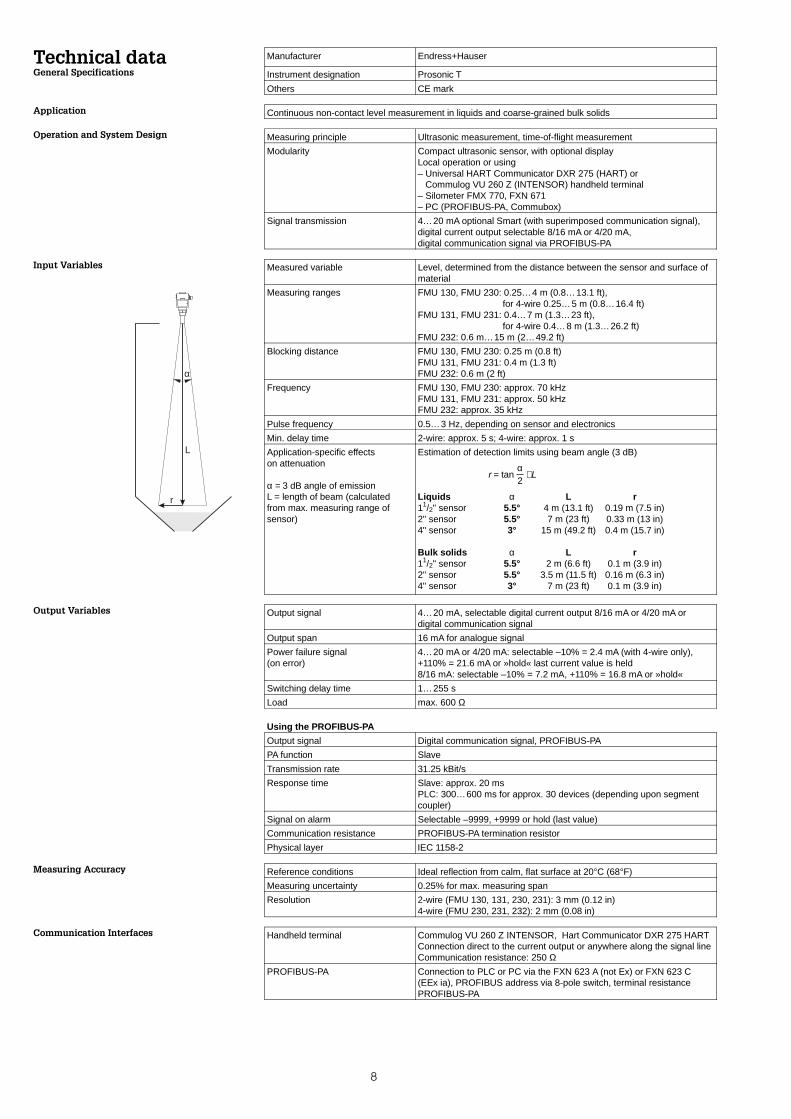
Technical data Manufacturer Endress+Hauser
General Specifications Instrument designation Prosonic T
Others CE mark
Application Continuous non-contact level measurement in liquids and coarse-grained bulk solids
Operation and System Design Measuring principle Ultrasonic measurement, time-of-flight measurement
Modularity Compact ultrasonic sensor, with optional display Local operation or using– Universal HART Communicator DXR 275 (HART) or Commulog VU 260 Z (INTENSOR) handheld terminal– Silometer FMX 770, FXN 671– PC (PROFIBUS-PA, Commubox)
Signal transmission 4…20 mA optional Smart (with superimposed communication signal),digital current output selectable 8/16 mA or 4/20 mA,digital communication signal via PROFIBUS-PA
Input Variables Measured variable Level, determined from the distance between the sensor and surface ofmaterial
Measuring ranges FMU 130, FMU 230: 0.25…4 m (0.8…13.1 ft), for 4-wire 0.25…5 m (0.8…16.4 ft)
FMU 131, FMU 231: 0.4…7 m (1.3…23 ft), for 4-wire 0.4…8 m (1.3…26.2 ft)
FMU 232: 0.6 m…15 m (2…49.2 ft)
Blocking distance FMU 130, FMU 230: 0.25 m (0.8 ft)FMU 131, FMU 231: 0.4 m (1.3 ft)FMU 232: 0.6 m (2 ft)
Frequency FMU 130, FMU 230: approx. 70 kHzFMU 131, FMU 231: approx. 50 kHzFMU 232: approx. 35 kHz
Pulse frequency 0.5…3 Hz, depending on sensor and electronics
Min. delay time 2-wire: approx. 5 s; 4-wire: approx. 1 s
Application-specific effects on attenuation
α = 3 dB angle of emissionL = length of beam (calculatedfrom max. measuring range ofsensor)
Estimation of detection limits using beam angle (3 dB)
r = tan α2
⋅ L
Liquids α L r11/2" sensor 5.5° 4 m (13.1 ft) 0.19 m (7.5 in)2" sensor 5.5° 7 m (23 ft) 0.33 m (13 in)4" sensor 3° 15 m (49.2 ft) 0.4 m (15.7 in)
Bulk solids α L r11/2" sensor 5.5° 2 m (6.6 ft) 0.1 m (3.9 in)2" sensor 5.5° 3.5 m (11.5 ft) 0.16 m (6.3 in)4" sensor 3° 7 m (23 ft) 0.1 m (3.9 in)
Output Variables Output signal 4…20 mA, selectable digital current output 8/16 mA or 4/20 mA ordigital communication signal
Output span 16 mA for analogue signal
Power failure signal(on error)
4…20 mA or 4/20 mA: selectable –10% = 2.4 mA (with 4-wire only),+110% = 21.6 mA or »hold« last current value is held8/16 mA: selectable –10% = 7.2 mA, +110% = 16.8 mA or »hold«
Switching delay time 1…255 s
Load max. 600 Ω
Using the PROFIBUS-PA
Output signal Digital communication signal, PROFIBUS-PA
PA function Slave
Transmission rate 31.25 kBit/s
Response time Slave: approx. 20 msPLC: 300…600 ms for approx. 30 devices (depending upon segmentcoupler)
Signal on alarm Selectable –9999, +9999 or hold (last value)
Communication resistance PROFIBUS-PA termination resistor
Physical layer IEC 1158-2
Measuring Accuracy Reference conditions Ideal reflection from calm, flat surface at 20°C (68°F)
Measuring uncertainty 0.25% for max. measuring span
Resolution 2-wire (FMU 130, 131, 230, 231): 3 mm (0.12 in)4-wire (FMU 230, 231, 232): 2 mm (0.08 in)
Communication Interfaces Handheld terminal Commulog VU 260 Z INTENSOR, Hart Communicator DXR 275 HARTConnection direct to the current output or anywhere along the signal lineCommunication resistance: 250 Ω
PROFIBUS-PA Connection to PLC or PC via the FXN 623 A (not Ex) or FXN 623 C(EEx ia), PROFIBUS address via 8-pole switch, terminal resistancePROFIBUS-PA
α
L
r
8

Application Conditions Orientation Perpendicular to the surface of the material1) Please check with Endress+Hauser before usingsensors at higher temperatures and higher pressures.
When sensors are subjected to high temperatures andpressures (with limiting conditions), it is recommendedthat the coupling (process connection) be tightened.
Medium temperature range 1) –40…+80°C (–40…+176°F) (built-in temperature sensor)
Operating temperature range(electronics)
–20…+60°C (–4…+140°F)
Storage temperature range –40…+80°C (–40…+176°F)
Operating pressure pabs1) Sensors with process connection G 11/2 and G 2: 3 bar (43.5 psi)
Sensor DN 100 or 4" with slip-on flange or mounting bracket: 2.5 bar(36.25 psi)
Climatic class DIN / IEC 68 T2-30 Db
Type of protection (EN 60529) IP 67 (NEMA 6), with housing cover open IP 20
Vibration resistance DIN IEC 68 T2-6 Tab.2.C (10…55 Hz)
Electromagnetic compatibility Interference immunity to EN 50082-2 and industrial standard NAMUR(Field strength 10 V/m), Interference emission to EN 50081-1
Explosion protection FMU 130/131 (2-wire Ex): PTB EEx ia IIC T6 (PTB in Germany only)FMU 230/231 (2-wire not Ex and 4-wire): withoutFMU 232 (4-wire): dust Ex, Zone 10 (BVS in Germany only)
Mechanical Design Construction Compact unit, Versions with threaded connection can be installed with 60 AF boxspanner, max. torque 15…20 Nm (11.1…14.8 ft lbs)
Dimensions See »Dimensions« page 12
Material Housing:threaded bossand sensor:
PBT (fibre-glass reinforced, flame-retarded)PVDFfor FMU 232 UP (unsatured polyester); sensor diaphragm stainless steel
Seals Between threaded boss and sensor, internal: EPDM sealon threaded boss, external: EPDM seal
Process connection FMU 130, FMU 230: G 11/2 or 11/2-11.5 NPT thread FMU 131, FMU 231: G 2 or NPT 2-11.5 NPT thread FMU 232: DN 100 or 4" with slip-on flange or mounting bracket
Cable entry Pg 16, Cable diameter 5…9 mm (0.2…0.35 in)Sleeves for connection thread G1/2,
1/2 NPT or M 20x1.5 supplied
Cable 2-wire:4-wire:
Use standard screened 2-wire cableUse standard screened 4-wire cable for signal transmission and powersupplyUnder certain circumstances, the digital communication signal may beaffected if unscreened cable is used.
Display and Operating Elements Display (LCD) 4-character display, with segment display for currentDimension L x B x H: 40 x 20 x 10 mm
(1.6 x 0.8 x 0.4 in)
LEDs Red: indicates alarm or warningGreen: Indicates power on (with 4-wire versions only) and entryacknowledgement
Power Supply AC voltagePower consumptionSwitch-on current
4-wire: 180…250 VAC; 90…127 VAC < 4 VA100 mA, pulse width half life time 70 ms
DC voltagePower consumptionSwitch-on current
4-wire: 18…36 VDC; 2-wire: 12…36 VDC
< 2,5 W7 A, pulse width half life time 2 ms
Current consumption FMU 130, 131, 230, 231: 12 mA ±1 mAFMU 231: 16 mA ±1 mA
Ripple(Smart-devices)
INTENSOR max. ripple (measured at 500 Ω) 0 Hz…100 Hz: USS=30 mVHART max. ripple (measured at 500 Ω) 47 Hz…125 Hz: USS=200 mVmax. noise (measured at 500 Ω) 500 Hz…10 kHz: Ueff.=2.2 mV
Electrical isolation The evaluation electronics is electrically isolated from the power supplyterminals with all 4-wire versions.
Supplementary Documentation Prosonic T System Information SI 021F/00/enProsonic T Compact transmitter for limit detection Technical Information TI 247F/00/enPlanning notes PROFIBUS-PA Technical Information TI 260F/00/en
9

Accessories Protective Hood for ElectronicHousing• Order No.: 942665-0000
Plug-in Display• Order-No.: 942663-0000
Adapter Flange FAU 70 E for FMU X30, X31• Order No.: 942636-XXXX
Slip-On Flange FAU 60for FMU 232 only• Order No.: FAU60-XOX
400 (15.6)120 (4.7)
120
(4.7
)30 (1.2
)
250
(9.7
)A
G
ø16 (0.6)
3.0 (0.12)mm (in)
Installation Bracketfor FMU X30, X31• G 11/2: A=55 mm
(2.2 in) Order-No: 942669-0000
• G 2: A=66 mm(2.6 in) Order-No:942669-0001
• Material: 1.4301(AISI 304)
11(0.4)
119 (4.7)
2(0.08)
120
(4.7
)
~12
3(~
4.8)
25(9.8)
25(9.8)
2 x M8enclosed
mm (in)
Mounting Bracketfor FMU 232• Order-No:
942666-0000• Material: 1.4301
(AISI 304)
Process connection12 DN 50 PN 1614 DN 80 PN 1615 DN 100 PN 16
Thread3 G 11/2 ISO 2284 G 2 ISO 228
Material2 1.4435 (AISI 316L)7 PPs (Polypropylene)
942636
Process connectionD DN 100, PN 16A ANSI 4", 150 psiJ JIS 16 K 100
MaterialP PPs (Polypropylene)S Steel paintedR 1.4571 (AISI 316L)
OFAU 60
144
(5.6
)
122 (4.7)
187 (7.3)
Protective hood forelectronics housing withdimensions in mm (in)
V H
16602
10

Product StructureVersionE Europe / Asia (cylindrical thread »G«)A America (conical thread »NPT«)
CertificatesB EEx ia IIC T6, Zone 1 (only in FRG)J FM, IS Class I, II, III, Division 1 Groups A-G (for Version A only)Q CSA, IS Class I, II, III Division 1 Groups A-G (for Version A only)
CommunicationF withoutA 4…20 mA, INTENSOR protocolB 4…20 mA, HART protocolP PROFIBUS-PA
Product designation
Process Connection Versions with G or NPTThreads
FMU 130: G 11/2 or 11/2 NPTRange: max. 2 m/6.6 ft (solids) or
max. 4 m/13.1 ft (liquids)
FMU 131: G 2 or 2 NPTRange: max. 3.5 m/11.5 ft (solids) or
max. 7 m/23 ft (liquids)
Enter "Y" for special certificates or communicationmode.
VersionE Europe / Asia (cylindrical thread »G«)A America (conical thread »NPT«)
CertificatesA StandardN CSA General Purpose (for Version A only)
CommunicationA 4…20 mA, 2-wire, without communicationB 4…20 mA, 2-wire, INTENSOR protocolC 4…20 mA, 2-wire, HART protocolD Power supply 18…36 VDC, 50/60 Hz, 4-wire, without communicationE Power supply 18…36 VDC, 50/60 Hz, 4-wire, HART protocolF Power supply 180…250 VAC, 50/60 Hz, 4-wire, without communicationG Power supply 180…250 VAC, 50/60 Hz, 4-wire, HART protocolJ Power supply 90…127 VAC, 50/60 Hz, 4-wire, without communicationK Power supply 90…127 VAC, 50/60 Hz, 4-wire, HART protocolP PROFIBUS-PA
Product designation
Process Connection Versions with G or NPTThreads
FMU 230: G 11/2 or 11/2 NPTRange: max. 2 m/6.6 ft (solids) or 2-wire: max. 4 m/13.1 ft (liquids)4-wire: max. 5 m/16.4 ft (liquids)
FMU 231: G 2 or 2 NPTRange: max. 3.5 m/11.5 ft (solids) or 2-wire: max. 7 m/23 ft (liquids)4-wire: max. 8 m/26.2 ft (liquids)
Enter "Y" for special certificates or communicationmode.
CertificatesA StandardF Dust Ex Zone 10 M FM Class II, Division 1, Groups E, F, GN CSA General PurposeR CSA Class II, Division 1, Groups E, F, G
Power Supply / CommunicationD Power supply 18…36 VDC, 50/60 Hz, 4-wire, without communicationE Power supply 18…36 VDC, 50/60 Hz, 4-wire, HART protocolF Power supply 180…250 VAC, 50/60 Hz, 4-wire, without communicationG Power supply 180…250 VAC, 50/60 Hz, 4-wire, HART protocolJ Power supply 90…127 VAC, 50/60 Hz, 4-wire, without communicationK Power supply 90…127 VAC, 50/60 Hz, 4-wire, HART protocolP PROFIBUS-PA 2-wire (in preparation)
Product designation
Process Connection Versions:Flange DN 100 / PN 16Flange ANSI 4" / 150 psiFlange JIS 16K 100Range: up to 7 m/23 ft (solids) or
max. 15 m/49.2 ft (liquids)
Enter "9" for special display or housing versions.
Housing / Cable Entry1 Plastic housing IP 67, Pg 16 IP 67
(with FMU 130, 131, 230, 231 for Version E only)2 Plastic housing NEMA 6, NPT 1/2"3 Plastic housing IP 67, M 20x1.5 (with FMU 130, 131, 230, 231 for Version E only)4 Plastic housing IP 67, G1/2 A (with FMU 130, 131, 230, 231 for Version E only)
Display1 Without plug-in display2 With plug-in display
Product designation
FMU 130 / 131 (2-wire, Ex)
FMU 230 / 231 (2-wire not Ex, 4-wire)
FMU 232 (4-wire)
For all instrument versions
11

Dimensions
TI 246F/00/en/04.98aEHF/CV4.2
~21
5 (~
8.4)
~87
(~
3.4)
22(0
.86)
22(0
.86)
~83
(~3.
3)
~26
0 (~
10.1
)
~26
0 (~
10.1
)125
(4.8
)
112 (4.3)
60 AF(2.34 in)
91 (3.5)105 (4.1)
ø39(ø1.5)
ø50(ø1.95)
G 22 NPT
G 1 /1 / NPT
12
12
mm (in)
Prosonic T FMU 130, 230 Prosonic T FMU 131, 231
Thread versions G 11/2 or 11/ 2-11.5 NPT G 2 or 2-11.5 NPT
Cable entry Pg 16, cable diameter 5…9 mmsleeves for connection thread G1/2;
1/2 NPT; M 20x1.5 supplied
When mounting in tapped holes to DIN 3852 Part 2, check that the recese diameter d4 is »wide«.
2 x M8
~21
5 (~
8.5)
158 (6.2)mm (in)
Prosonic T FMU 232
Mounting with slip-on flange or mountingbracket
Cable entry Pg 16, cable diameter 5…9 mmsleeves for connection threadG1/2;
1/2 NPT; M 20x1.5 supplied
10.97/MTM
Endress+HauserGmbH+Co.Instruments InternationalP.O. Box 2222D-79574 Weil am RheinGermany
Tel. (07621) 975-02Tx 773926Fax (07621) 975345http://www.endress.com
Hauser+EndressNothing beats know-how