Hart Cooley Bvent Sizing Guide
32
Sizing Guide - Type B Gas Vent for Category 1 Appliances - All-Fuel Chimney for Oil-Fired Appliances & Open-Face Fireplaces
-
Upload
jimbobofdundee -
Category
Documents
-
view
93 -
download
2
Transcript of Hart Cooley Bvent Sizing Guide
Sizing Guide
- Type B Gas Ventfor Category 1 Appliances
- All-Fuel Chimneyfor Oil-Fired Appliances& Open-Face Fireplaces

Order information:To order Hart & Cooley products,please contact any authorizedHart & Cooley distributor orcall 800.433.6341.
When you purchase Hart & Cooley products, youalso receive the full support of Hart & Cooleytechnical and customer service.
Technical and customer service:800.433.6341 toll-free616.656.8200 phone800.223.8461 toll-free fax616.656.6399 fax
Internet address:http: //www.hartandcooley.com
Install confidence with these other qualityHart & Cooley products available:• Registers, Grilles & Diffusers• Type B Gas Vent Systems• Special Gas Vent• Model TLC All-Fuel Chimney• Duct System Components• Flexible Duct Systems
www.hartandcooley.com Sizing Guide 1
Page
Section 1 Type B Double-Wall Gas Vent Systems 3
General Rules 4
Types of Systems and Definitions 7
Single-Appliance Vents 8
Multiple-Appliance Vents 13
Multiple-Story Venting 19
Section 2 Factory-Built All-Fuel Chimney Systems 23
Table of Contents

2 Sizing Guide www.hartandcooley.com
ForewordThis Guide is a compilation of the system design andapplication procedures for all Hart & Cooley® GasVenting and Chimney products. The first section isspecifically devoted to the design of Double-WallType B Gas Vent Systems for use with equipmentcertified by the American Gas Association orCanadian Gas Association for use with B Vent.
This Guide has been prepared not only for theconvenience and assistance of contractors but also forthe assistance of building inspectors, engineeringfirms and architects, as well as for training.
The basis for the material in this Guide is the standard engineering application of the scientific lawsfor the behavior of fluid flow and heat transfer. In addition, these methods have been proved valid bymany decades of field and laboratory experience byengineers, in design and application, and utilities andcode authorities.
THIS GUIDE SHOULD BE USED IN ADDITION TO,NOT AS REPLACEMENT FOR, HART & COOLEY®
INSTALLATION INSTRUCTIONS.
ALWAYS READ AND COMPLY WITH THE MANU-FACTURER’S INSTALLATION INSTRUCTIONSSUPPLIED WITH THE APPLIANCE.
NOTE:
CAUTION:
Hart & Cooley is a registered trademark.
Additional references for the development of the material in this Guide were from the following:
National Fuel Gas Code, NFPA Standard 54 ANSIZ223.1
Standard for the Installation of Oil-BurningEquipment 2006 Edition, NFPA 31
American Society of Heating, Refrigerating and AirConditioning Handbook, Equipment
International Mechanical Code
The capacities given in the Tables for Type B GasVenting are consistent with those found inpublications by the appliance manufacturers andNFPA 54 National Fuel Gas Code.
The capacities given in Section 2 tables for all-fuelchimney are consistent with those found in NFPA 31,Standard for Oil-Burning Equipment.
For information on products for use with the systemsdesigned by use of this Guide, refer to the various specific product literature.

Type B Double-WallGas Vent Systems
General Rules
Types of Systems and Capacity TablesSingle-Appliance VentsMultiple-Appliance VentsMultiple-Story Venting
1
3
4 Sizing Guide www.hartandcooley.com
Type B Double-Wall Gas VentsSystemsThe Tables given in Section 1 apply to system design usingHart & Cooley® Type B Gas Vents and to Model TLCChimneys when used for venting listed Category I gas-fired, draft-hood-equipped or fan-assisted combustionappliances. At no time should a venting system for a listedCategory II, III, or IV appliance be sized with these tables;instead, follow the appliance manufacturer’s instructions.
ClearanceInstallations must provide the proper clearances to combustible materials as specified in the appropriateUnderwriters Laboratories Inc. conditions for Listing, as stated in the product catalogs and embossed on thevent pipe. Hart & Cooley® systems to be designed usingSection 1 of this Guide are shown below with theirproper clearances.
Type B Hart & Cooley® pipe sizes 3 through 24 inchesin diameter require 1 inch of airspaceclearance throughout the entire length.
Model TLC Hart & Cooley® chimney sizes 5 through14 inches in diameter require 2 inches ofairspace clearance to combustibleconstruction.
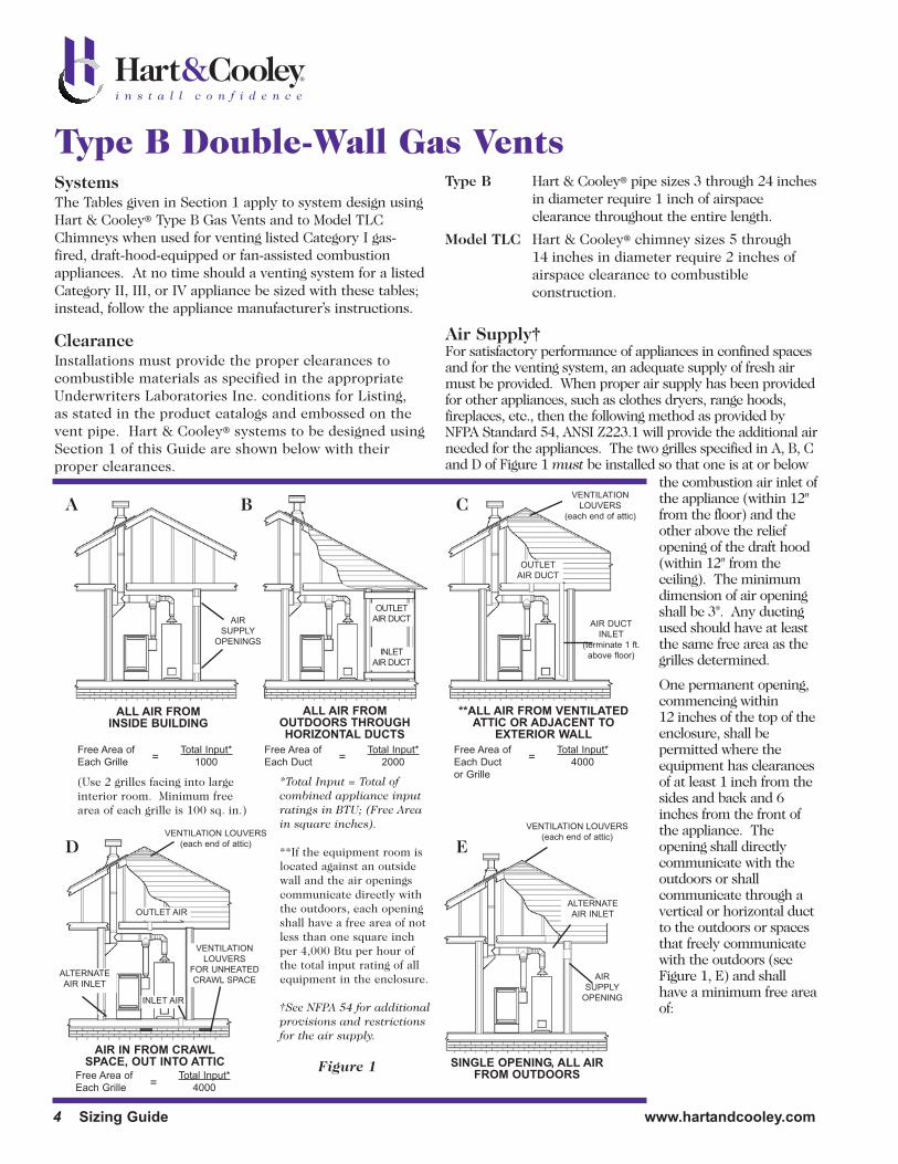
Air Supply†For satisfactory performance of appliances in confined spacesand for the venting system, an adequate supply of fresh airmust be provided. When proper air supply has been providedfor other appliances, such as clothes dryers, range hoods,fireplaces, etc., then the following method as provided byNFPA Standard 54, ANSI Z223.1 will provide the additional airneeded for the appliances. The two grilles specified in A, B, Cand D of Figure 1 must be installed so that one is at or below
A B
D E
CVENTILATION
LOUVERS
(each end of attic)
VENTILATION LOUVERS
(each end of attic)
VENTILATION LOUVERS
(each end of attic)
AIR DUCT
INLET
(terminate 1 ft.
above floor)
ALTERNATE
AIR INLET
ALTERNATE
AIR INLET
VENTILATION
LOUVERS
FOR UNHEATED
CRAWL SPACE
AIR
SUPPLY
OPENINGS
AIR
SUPPLY
OPENING
OUTLET
AIR DUCT
OUTLET AIR
INLET AIR
OUTLET
AIR DUCT
INLET
AIR DUCT
ALL AIR FROM INSIDE BUILDING
ALL AIR FROM OUTDOORS THROUGHHORIZONTAL DUCTS
**ALL AIR FROM VENTILATEDATTIC OR ADJACENT TO
EXTERIOR WALL
AIR IN FROM CRAWLSPACE, OUT INTO ATTIC SINGLE OPENING, ALL AIR
FROM OUTDOORS
Free Area of
Each Grille
Total Input*
1000=
Free Area of
Each Grille
Total Input*
4000=
Free Area of
Each Duct
Total Input*
2000=Free Area of
Each Duct
or Grille
Total Input*
4000=
(Use 2 grilles facing into largeinterior room. Minimum freearea of each grille is 100 sq. in.)
*Total Input = Total of combined appliance inputratings in BTU; (Free Areain square inches).
**If the equipment room islocated against an outsidewall and the air openingscommunicate directly withthe outdoors, each openingshall have a free area of notless than one square inchper 4,000 Btu per hour ofthe total input rating of allequipment in the enclosure.
†See NFPA 54 for additionalprovisions and restrictionsfor the air supply.
the combustion air inlet ofthe appliance (within 12"from the floor) and theother above the reliefopening of the draft hood(within 12" from theceiling). The minimumdimension of air openingshall be 3". Any ductingused should have at leastthe same free area as thegrilles determined.
One permanent opening,commencing within12 inches of the top of theenclosure, shall bepermitted where theequipment has clearancesof at least 1 inch from thesides and back and 6inches from the front ofthe appliance. Theopening shall directlycommunicate with theoutdoors or shallcommunicate through avertical or horizontal ductto the outdoors or spacesthat freely communicatewith the outdoors (seeFigure 1, E) and shallhave a minimum free areaof:
Figure 1
a. 1 inch2/3000 Btu/hour of the total input rating of allequipment located in the enclosure, and
b. Not less than the sum of the areas of all vent connectorsin the confined space.
A combination of air supplied from both the indoorsand outdoors is also permitted. See NFPA 54 for theseprovisions.
Local Building CodeShould the local building code differ fromrecommendations given in this Guide, consult withyour building inspector or other local administrativeauthority. As stated in the Foreword, the informationgiven is based on the latest scientific data, which hasbeen further verified by a long and satisfactory usehistory. These data and practices given herein willinvariably provide better results than practicesrequired by an obsolete code.
Correction for AltitudeThe vent system should always be designed for the sealevel nameplate rating (greatest input when unit hasmodulated input) of the appliance, regardless of the actualderated operating input required by the local altitude.
Outside VentsThe gas vent sizing tables are not applicable to outside(exposed) chimneys or vents below the roofline perNFPA 54. A Type B vent lining an exposed masonrychimney is considered to be an enclosed vent system,and these tables may be used.
ConnectorsSingle-wall pipe (stovepipe) is not recommended for usein TYPE B venting systems. Because of the higher heatloss from the flue products, the draft is reduced andcondensation can occur. The resulting moisture maycorrode the pipe and will likely leak out on the buildingand contents, causing damage.
Where single-wall connector pipe usage is accepted localpractice, the following considerations must be followed:
1. Minimum clearance to combustibles is 6 inchesinstead of the 1 inch required for Hart & Cooley®
vent.
2. The heat loss is roughly double that for B-Vent, so DONOT USE IN ANY COLD OR CONCEALED SPACES,AS CONDENSATION WILL RESULT AND LEAD TOVENTING FAILURE AND POSSIBLE OTHER DAMAGE.
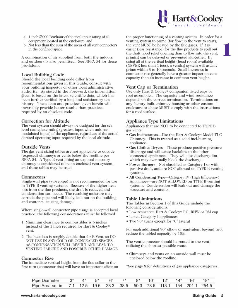
Connector RiseThe immediate vertical height from the flue collar to thefirst turn (connector rise) will have an important effect on
the proper functioning of a venting system. In order for aventing system to prime (for flow up the vent to start),the vent MUST be heated by the flue gases. If it iseasier (less resistance) for the flue products to spill outthe draft hood relief opening than to flow into the vent,priming can be delayed or prevented altogether. Byusing all of the vertical height (head room) available(NEVER less than 1 foot), a venting system will usuallyprime within 8 to 10 seconds. Small increases inconnector rise generally have a greater impact on ventcapacity than an increase in common vent height.
Vent Cap or TerminationUse only Hart & Cooley® companion listed caps orroof assemblies. The capacity and wind resistancedepends on the correct termination. Terminations onany factory-built chimney housing or other customenclosure or chase MUST comply with the instructionsfor a roof surface.
Appliance Type LimitationsAppliances that are NOT to be connected to TYPE B gas vents:• Gas Incinerators—Use the Hart & Cooley® Model TLC
Chimney. This is treated as a solid fuel-burning appliance.
• Gas Clothes Dryers—These produce positive pressure discharge and will cause backflow to the other connected appliances. They will also discharge lint,which may eventually block the discharge.
• Power Burners—Not classified as Category I or withpositive draft, and are NOT allowed on TYPE B ventingsystems.
• All Condensing Type—Category IV (High Efficiency)Appliances—are NOT ALLOWED on TYPE B ventingsystems. Condensation will leak out and damage thestructure and contents.
Table LimitationsThe Tables in Section 1 of this Guide include the following considerations:• Low resistance Hart & Cooley® RC, RHW or RM cap• Listed Category I appliances• Two 90° turns except for “0” lateral
For each additional 90° elbow or equivalent beyond two,reduce the tabled capacity by 10%.
The vent connector should be routed to the vent,utilizing the shortest possible route.
• Chimneys and vents on an outside wall must beenclosed below the roofline.
*See page 8 for definitions of gas appliance categories.
1
Pipe Diameter 3" 4" 5" 6" 7" 8" 10" 12" 14" 16" 18"Pipe Area sq. in. 7.1 12.5 19.6 28.3 38.5 50.3 78.5 113.1 154 201.1 254.5
www.hartandcooley.com Sizing Guide 5

6 Sizing Guide www.hartandcooley.com
Type B Double-Wall Gas VentsCondensationThe condensing of water vapor from the products ofcombustion of gas fuels can be minimized with the useof these sizing tables. When the vent system isdesigned properly, dilution air, which may enter a drafthood (if available), reduces the temperature at whichwater vapor will condense (dew point). Exceptions thatwill cause condensation are as follows:
A. Temporarily (for a few seconds) after burner ignition,condensation will form on the cold inner liner of thevent. Before it develops to drop size, the liner willhave been heated above the dew point, and thiscondensate will reevaporate. If the vent is locatedoutdoors and the temperature is very low,condensation may continue. This is a good reason foravoiding this type of installation. It is also importantNOT to extend the vent above the roof more than therules require.
B. Extremely long vents or long laterals in unheatedspaces can allow the flue products to cool to thedew point. DO NOT WRAP INSULATIONAROUND B-VENT TRYING TO PREVENTCONDENSATION. This method is not reliable andmay contribute to other problems.
C. AIR SUPPLY, as covered earlier, is of greatimportance to the proper operation of a vent. Againif sufficient make-up air is not available to replacethat required by the burner and the draft hood, thesystem is starved. The first result is that less airenters the draft hood, and the dew pointtemperature rises. In other words, condensationcan occur at a higher temperature. At some pointin the dilution percent, condensation will start inthe vent. Further starving for air can result inwater running out of the vent, and damage willresult to the structure and contents.
Remember—When in doubt for any reason, such asdimensions being questionable, a borderline chart selection, or overhead clearance for maximumconnector rise in doubt, ALWAYS USE THE NEXTLARGER SIZE and prevent problems that might occur.This does not apply to table minimums.
Vent CapsListed vent caps for double-wall Type B vents aredesigned to serve two purposes, (1) prevent rain anddebris from entering the vent, and (2) help prevent adowndraft condition in the vent due to adverse wind conditions. These Tables apply to vents, vent caps orroof housing of the same make and style as the vent.For safe, efficient operation, DO NOT use combinationroof jacks or caps or termination designs fabricated by
other than the vent manufacturer. ALWAYS install anapproved vent cap immediately after installation of thevent to exclude debris and prevent damage.
Wall Furnace VentsWall furnaces (vented recessed heaters) require a 12-foot minimum vent height measured from the floorto the top of the vent, or, in the case of combinedvents, to the top of the vent connector. Many ventedwall furnaces require connection to oval vents.
Flashing and Top Assembly Using a CapModel RHW/RM Metal Cap TerminationModel RHW/RM cap sizes 3" through 12" round arelisted by U.L. for installation on gas vents terminating asufficient distance from the roof so that no dischargeopening is less than 2 feet horizontally from the roofsurface. The lowest discharge opening shall be nocloser than the minimum height shown in the Table inFigure 2. These minimum heights may be usedprovided that the vent is NOT less than 8 feet from anyvertical wall. This also means that no installation shallterminate by piercing a wall with a short pipe and cap.These requirements satisfy all national codes.
Termination Dimensions for Type RHW/RM Caps
Flat to 6/12 1.0Over 6/12 to 7/12 1.25Over 7/12 to 8/12 1.5Over 8/12 to 9/12 2.0Over 9/12 to 10/12 2.5Over 10/12 to 11/12 3.25Over 11/12 to 12/12 4.0Over 12/12 to 14/12 5.0Over 14/12 to 16/12 6.0Over 16/12 to 18/12 7.0Over 18/12 to 20/12 7.5Over 20/12 to 21/12 8.0
Model RHW/RM caps are listed under the “Draft Lossand Wind Effect” requirements of UL Standard 441.
MIN. HEIGHT SEE TABLE
Figure 2
Roof Pitch
Minimum Heightfrom Roof to
Lowest DischargeOpening - Feet

Metal Cap TerminationsCap sizes 14" through 30" diameters are for gas ventsthat extend at least 2 feet above the highest pointwhere they pass through a building and at least 2 feethigher than any portion of the building within 10 feet.If any adjacent structures are within 10 feet of the ventand are higher, then the vent MUST terminate at least2 feet above these structures. This recommendationshould be followed unless local code requirements stateotherwise.
Large offsets in the attic space are discouraged.However, small offsets (laterals) may be used tominimize the amount of vent pipe that must beexposed above the roof in order to comply with theabove. NO gas vent should be terminated less than5 feet in vertical height above the highest connectedappliance draft hood outlet.
General Termination ConsiderationsA cap or chimney housing offers protection against the entrance of rain, snow and debris, as well as birds,and will minimize the effect of wind on the vent. It willprotect the vent from downdrafts due to a wind thatimpinges directly upon the vent. However, no ventcap, cowl or top can overcome the adverse effect of aregion of high static pressure around the vent terminalnor the effect of an interior region of low pressure.Regions of high static pressure around the ventterminal can be avoided by following the general rulefor the vent termination given above. Low or negativeinterior pressures in the building may be caused by (1)failure to provide for combustion air, (2) excessive useof exhaust fans, and (3) tight construction resulting inthe lack of infiltration air. Vented clothes dryers andfireplaces will also remove large amounts of air fromthe interior, tending to produce a low interior pressure.
This also means that no B Vent installation shall terminate by piercing a wall with a short vertical orhorizontal pipe and a cap.
DefinitionsA SINGLE-APPLIANCE VENT is an independent ventfor one appliance (Figure 3).
TOTAL HEIGHT (H) is the vertical distance measuredbetween the appliance collar connection and the venttermination (Figure 3).
TOTAL LATERAL LENGTH (L) is the actual horizontaldistance or length of offset between the appliance collarand the main vertical portion of vent (Figure 3).
MULTIPLE-APPLIANCE VENT is a venting systemcombining the connectors of two or more appliances atone floor level to a common vertical vent. Connector ina combined vent system connects an individual applianceflue collar to the common vent or manifold (Figure 4).
MINIMUM TOTAL VENT HEIGHT is the vertical distance measured from the tallest appliance flue collar outlet in the system to the termination of thevent (see Figures 3 and 4). This minimum height is afixed dimension for any one vent system regardless ofthe number or placement of appliances in the system.
CONNECTOR RISE for any appliance in a vent systemis the vertical distance from the flue collar outlet to thepoint where the next connector joins the system (seeFigure 4).
COMMON VENT is that portion of the venting systemabove the lowest interconnection. When the commonvent is entirely vertical, the system is called aVERTICAL or V type. All others are called LATERALor L type (see Figure 4).
FAN-ASSISTED COMBUSTION SYSTEM is an appliance equipped with a fan to either draw or forceproducts of combustion through the combustion chamber and/or heat exchanger.
FAN MIN refers to the minimum input rating of aCategory 1 fan-assisted appliance attached to the vent.
www.hartandcooley.com Sizing Guide 7
Figure 3
TOTAL
HEIGHT
H
COMMON VENT
IS VERTICAL (V)
ALLAPPLIANCES
DIRECTLY
CONNECTED
TOTAL
LATERAL
LENGTH
L
AP
PLIA
NC
E
A. B.
C.
H
RISE
OFFSETELBOW
OR TEE
RISE
D.
COMMON VENT WITH LATERAL (L)
MANIFOLD
1
Figure 4

8 Sizing Guide www.hartandcooley.com
Type B Double-Wall Gas VentsFAN MAX refers to the maximum input rating of aCategory I fan-assisted appliance attached to the vent.
NAT MAX refers to the maximum input rating of aCategory I draft-hood-equipped appliance attached tothe vent. There are no minimum appliance inputratings for draft-hood-equipped appliances.
FAN+FAN refers to the maximum combined inputrating of two or more fan-assisted appliances attachedto the common vent.
FAN+NAT refers to the maximum combined inputrating of one or more fan-assisted appliances and oneor more draft-hood-equipped appliances attached to thecommon vent.
NAT+NAT refers to the maximum combined inputrating of two or more draft-hood-equipped appliancesattached to the common vent.
NA means not allowed due to physical or geometricconstraints.
DRAFT HOOD is a device built into an appliance, ormade a part of the vent connector from an appliance,which is designed to (1) provide for the ready escape ofthe flue gases from the appliance in the event of nodraft, backdraft, or stoppage beyond the draft hood;(2) prevent a backdraft from entering the appliance;and (3) neutralize the effect of stack action of thechimney or gas vent upon the operation of theappliance.
VENT is a passageway used to convey flue gases fromgas utilization equipment, or its vent connector, to theoutside atmosphere.
VENT CONNECTOR is the pipe or duct that connects afuel gas-burning appliance to a vent or chimney.
FLUE COLLAR is that portion of an appliance designedfor the attachment of a draft hood, appliance adapter,vent connector or venting system.
FORCED DRAFT indicates that the combustion air fanor blower is located ahead of the burner compartment.
INDUCED DRAFT indicates that the combustion air fanor blower is located at or after the exit of flue productsfrom the heat exchanger.
CONDENSING APPLIANCE is one which by reason ofhaving sufficient heat removed from its products ofcombustion, water vapors will condense in its heatexchanger and continue to condense in the ventingsystem.
Definition of ANSI Categories of Appliances*
Gas Appliances Categories. Vented gas appliances areclassified for venting purposes into four categories asfollows:
Category I An appliance that operates with a negativevent static pressure and with a vent gastemperature that avoids excessivecondensate production in the vent.
Category II An appliance that operates with a negativevent static pressure and with a vent gastemperature that may cause excessivecondensate production in the vent.
Category III An appliance that operates with a positivevent static pressure and with a vent gastemperature that usually avoids excessivecondensate production in the vent.
Category IV An appliance that operates with a positivevent static pressure and with a vent gastemperature that causes excessivecondensate production in the vent.
*Remember that these definitions apply to theappliance and do not necessarily reflect theperformance of the connected vent system.
Single-Appliance Vent Systems
General Rules for Venting Single Appliances.Normally, a vent equal to the size of the draft hoodoutlet can be considered satisfactory for venting asingle appliance. It is important to note that this rulemay NOT apply to cases where an extra high vent isrequired, and it may be desirable to calculate thesystem to determine whether is it possible to reducethe size of the vent.

How to Use Single-Appliance Vent TablesTo determine the proper vent size for a single-appliancevent, use Table 1 or 2 (pages 10-12).
• Determine Total Height (H) and Total Lateral Length(L) based on location of appliance and vent and theheight to vent termination.
• Read down the Total Height (H) column at the left toa height equal to the Total Height.
• Select the horizontal row for the appropriate Lengthof Lateral (L) (zero for straight vertical vents).
• Read across to the column that represents theappliance type and shows a capacity equal to orgreater than the appliance nameplate input for draft-hood-equipped appliances or that falls between theFAN Min and Max for FAN-assisted appliances.
• If the vent size shown at the top of the columncontaining the correct capacity is equal to or largerthan the appliance draft hood, use the vent sizeshown by the Table.
• If the vent shown is smaller than the draft hood size,see Draft Hood to Vent Reduction on page 9.
ExampleA typical example of use of the Tables for Single-Appliance Venting is shown in Figure 5. The furnace has an input rating of 80,000 BTU per hour and is fan-assisted. Total Height (H) of the vent is 30 feet with a10- foot Total Lateral Length (L). The entire system isType B gas vent.
ProcedureGo down Vent Height (H) column of Table 1 to 30-footheight with a 10-foot lateral under the FAN Min andFAN Max column giving 37,000 and 150,000 BTUH fora 4-inch vent. Generally, the smallest diameter that
will do the job is preferred. Note that if this systemwere to have a single-wall connector, Table 2 wouldhave to be used. However, there is no solution!
Draft Hood to Vent ReductionIf the vent size determined from the Tables is lessthan the size of a draft hood outlet or flue collar, thesmaller vent may be used, provided:
a) The vent is at least 10 feet high. When a vent is lessthan 10 feet high, the vent should be at least as largeas the flue collar outlet.
b) Vents for draft hoods or flue collars 12 inches indiameter or less should NOT be reduced more thanone pipe size. A 6- to 5-inch or a 12- to 10-inchreduction is a one- pipe size reduction. For larger gas-burning equipment, such as boilers having draft hoodsizes from 14 to 24 inches in diameter, reductions ofmore than two pipe sizes are NOT recommended(24- to 20-inch is a two-size reduction).
c) The maximum capacity listed in the tables for a fan-assisted appliance is reduced by 10 percent.
d) Regardless of the size vent shown by the Tables forsuch appliances, DO NOT connect any 4-inch drafthoods to 3-inch vents. This provision does notapply to fan-assisted appliances.
Additional Guidelines for Single-ApplianceVent SystemsThe flow area of the vertical vent shall not exceedseven times the flow area of the appliance flue collararea or the draft hood outlet area. For instance, if:
The flue collar diameter is: 3" 4" 5" 6" 7" 8"The maximum commonvent diameter allowed is: 8" 10" 12" 14" 18" 20"
Single-appliance vent configurations with zero (0)lateral lengths in Tables 1 and 2 have no elbows in thesystem. For all other vent configurations withindicated lateral lengths, the vent table capacitiesinclude two 90° elbows. For each additional 90° fittingor equivalent, the maximum capacity listed shall bereduced by 10%. Two 45° elbows are equivalent to one90° elbow. Two 90° elbows connected together areequivalent to three in the system.
Interpolation is permitted between table entries.Extrapolation beyond table entries is not permitted.
1
Figure 5
80,000 BTUH
FAN-ASSISTED
FURNACE
10 FT.
30 FT.
www.hartandcooley.com Sizing Guide 9

Type B Double-Wall Gas Vent Capacitieswith Type B Double-Wall Connector
Single Category I Appliance
10 Sizing Guide www.hartandcooley.com
NAT NAT NAT NAT NAT NAT NAT
Min Max Max Min Max Max Min Max Max Min Max Max Min Max Max Min Max Max Min Max Max
6 0 0 78 46 0 152 86 0 251 141 0 375 205 0 524 285 0 698 370 0 1121 570
2 13 51 38 18 97 67 27 157 105 32 232 157 44 321 217 53 425 285 75 675 455
4 21 49 34 30 94 64 39 153 103 50 227 153 66 316 211 79 419 279 110 668 445
6 25 46 32 36 91 61 47 149 100 59 223 149 78 310 205 93 413 273 128 661 435
8 0 0 84 50 0 165 94 0 276 155 0 415 235 0 583 320 0 780 415 0 1261 660
2 12 57 40 16 109 75 25 178 120 28 263 180 42 365 247 50 483 322 71 770 515
5 23 53 38 32 103 71 42 171 115 53 255 173 70 356 237 83 473 313 115 758 503
8 28 49 35 39 98 66 51 164 109 64 247 165 84 347 227 99 463 303 137 746 490
10 0 0 88 53 0 175 100 0 295 166 0 447 255 0 631 345 0 847 450 0 1377 720
2 12 61 42 17 118 81 23 194 129 26 289 195 40 402 273 48 533 355 68 852 560
5 23 57 40 32 113 77 41 187 124 52 280 188 68 392 263 81 522 346 112 839 547
10 30 51 36 41 104 70 54 176 115 67 267 175 88 376 245 104 504 330 142 817 525
15 0 0 94 58 0 191 112 0 327 187 0 502 285 0 716 390 0 970 525 0 1596 840
2 11 69 48 15 136 93 20 226 150 22 339 225 38 475 316 45 633 414 63 1019 675
5 22 65 45 30 130 87 39 219 142 49 330 217 64 463 300 76 620 403 105 1003 660
10 29 59 41 40 121 82 51 206 135 64 315 208 84 445 288 99 600 386 135 977 635
15 35 53 37 48 112 76 61 195 128 76 301 198 98 429 275 115 580 373 155 953 610
20 0 0 97 61 0 202 119 0 349 202 0 540 307 0 776 430 0 1057 575 0 1756 930
2 10 75 51 14 149 100 18 250 166 20 377 249 33 531 346 41 711 470 59 1150 755
5 21 71 48 29 143 96 38 242 160 47 367 241 62 519 337 73 697 460 101 1133 738
10 28 64 44 38 133 89 50 229 150 62 351 228 81 499 321 95 675 443 130 1105 710
15 34 58 40 46 124 84 59 217 142 73 337 217 94 481 308 111 654 427 150 1078 688
20 48 52 35 55 116 78 69 206 134 84 322 206 107 464 295 125 634 410 167 1052 665
30 0 0 100 64 0 213 128 0 374 220 0 587 336 0 853 475 0 1173 650 0 1977 1060
2 9 81 56 13 166 112 14 283 185 18 432 280 27 613 394 33 826 535 54 1351 865
5 21 77 54 28 160 108 36 275 176 45 421 273 58 600 385 69 811 524 96 1332 851
10 27 70 50 37 150 102 48 262 171 59 405 261 77 580 371 91 788 507 125 1301 829
15 33 64 NA 44 141 96 57 249 163 70 389 249 90 560 357 105 765 490 143 1272 807
20 56 58 NA 53 132 90 66 237 154 80 374 237 102 542 343 119 743 473 160 1243 784
30 NA NA NA 73 113 NA 88 214 NA 104 346 219 131 507 321 149 702 444 195 1189 745
50 0 0 101 67 0 216 134 0 397 232 0 633 363 0 932 518 0 1297 708 0 2231 1195
2 8 86 61 11 183 122 14 320 206 15 497 314 22 715 445 26 975 615 41 1620 1010
5 20 82 NA 27 177 119 35 312 200 43 487 308 55 702 438 65 960 605 90 1600 996
10 26 76 NA 35 168 114 45 299 190 56 471 298 73 681 426 86 935 589 118 1567 972
15 59 70 NA 42 158 NA 54 287 180 66 455 288 85 662 413 100 911 572 136 1536 948
20 NA NA NA 50 149 NA 63 275 169 76 440 278 97 642 401 113 888 556 151 1505 924
30 NA NA NA 69 131 NA 84 250 NA 99 410 259 123 605 376 141 844 522 183 1446 876
100 0 NA NA NA 0 218 NA 0 407 NA 0 665 400 0 997 560 0 1411 770 0 2491 1310
2 NA NA NA 10 194 NA 12 354 NA 13 566 375 18 831 510 21 1155 700 30 1975 1170
5 NA NA NA 26 189 NA 33 347 NA 40 557 369 52 820 504 60 1141 692 82 1955 1159
10 NA NA NA 33 182 NA 43 335 NA 53 542 361 68 801 493 80 1118 679 108 1923 1142
15 NA NA NA 40 174 NA 50 321 NA 62 528 353 80 782 482 93 1095 666 126 1892 1124
20 NA NA NA 47 166 NA 59 311 NA 71 513 344 90 763 471 105 1073 653 141 1861 1107
30 NA NA NA NA NA NA 78 290 NA 92 483 NA 115 726 449 131 1029 627 170 1802 1071
50 NA NA NA NA NA NA NA NA NA 147 428 NA 180 651 405 197 944 575 241 1688 1000
Vent
Height
H
(ft)
Appliance Input Rating Limits in Thousands of BTU Per Hour
Vent and Connector Diameter - D
Lateral
L
(ft)FAN FAN FAN FAN
6" 7" 10"
FAN FAN FAN
3" 4" 5" 8"
Table 1
www.hartandcooley.com Sizing Guide 11
1
NAT NAT NAT NAT NAT NAT NAT
Min Max Max Min Max Max Min Max Max Min Max Max Min Max Max Min Max Max Min Max Max
6 0 0 1645 850 0 2267 1170 0 2983 1530 0 3802 1960 0 4721 2430 0 5737 2950 0 6853 3520
2 103 982 650 138 1346 890 178 1769 1170 225 2250 1480 296 2782 1850 360 3377 2220 426 4030 2670
4 147 975 640 191 1338 880 242 1761 1160 300 2242 1475 390 2774 1835 469 3370 2215 555 4023 2660
6 171 967 630 219 1330 870 276 1753 1150 341 2235 1470 437 2767 1820 523 3363 2210 618 4017 2650
8 0 0 1858 970 0 2571 1320 0 3399 1740 0 4333 2220 0 5387 2750 0 6555 3360 0 7838 4010
2 98 1124 745 130 1543 1020 168 2030 1340 212 2584 1700 278 3196 2110 336 3882 2560 401 4634 3050
5 154 1110 733 199 1528 1010 251 2013 1330 311 2563 1685 398 3180 2090 476 3863 2545 562 4612 3040
8 180 1097 720 231 1514 1000 289 2000 1320 354 2552 1670 450 3163 2070 537 3850 2530 630 4602 3030
10 0 0 2036 1060 0 2825 1450 0 3742 1925 0 4782 2450 0 5955 3050 0 7254 3710 0 8682 4450
2 93 1244 850 124 1713 1130 161 2256 1480 202 2868 1890 264 3556 2340 319 4322 2840 378 5153 3390
5 149 1229 829 192 1696 1105 243 2238 1461 300 2849 1871 382 3536 2318 458 4301 2818 540 5132 3371
10 187 1204 795 238 1669 1080 298 2209 1430 364 2818 1840 459 3504 2280 546 4268 2780 641 5099 3340
15 0 0 2380 1240 0 3323 1720 0 4423 2270 0 5678 2900 0 7099 3620 0 8665 4410 0 10393 5300
2 86 1495 985 114 2062 1350 147 2719 1770 186 3467 2260 239 4304 2800 290 5232 3410 346 6251 4080
5 140 1476 967 182 2041 1327 229 2696 1748 283 3442 2235 355 4278 2777 426 5204 3385 501 6222 4057
10 177 1446 936 227 2009 1289 283 2659 1712 346 3402 2193 432 4234 2739 510 5159 3343 599 6175 4019
15 202 1418 905 257 1976 1250 318 2623 1675 385 3363 2150 479 4192 2700 564 5115 3300 665 6129 3980
20 0 0 2637 1350 0 3701 1900 0 4948 2520 0 6376 3250 0 7988 4060 0 9785 4980 0 11753 6000
2 81 1694 1100 107 2343 1520 139 3097 2000 175 3955 2570 220 4916 3200 269 5983 3910 321 7154 4700
5 135 1674 1079 174 2320 1498 219 3071 1978 270 3926 2544 337 4885 3174 403 5950 3880 475 7119 4662
10 172 1641 1045 220 2282 1460 273 3029 1940 334 3880 2500 413 4835 3130 489 5896 3830 573 7063 4600
15 195 1609 1018 248 2245 1425 306 2988 1910 372 3835 2465 459 4786 3090 541 5844 3795 631 7007 4575
20 217 1578 990 273 2210 1390 335 2948 1880 404 3791 2430 495 4737 3050 585 5792 3760 689 6953 4550
30 0 0 3004 1550 0 4252 2170 0 5725 2920 0 7420 3770 0 9341 4750 0 11483 5850 0 13848 7060
2 74 2004 1310 98 2786 1800 127 3696 2380 159 4734 3050 199 5900 3810 241 7194 4650 285 8617 5600
5 127 1981 1289 164 2759 1775 206 3666 2350 252 4701 3020 312 5863 3783 373 7155 4622 439 8574 5552
10 164 1944 1254 209 2716 1733 259 3617 2300 316 4647 2970 386 5803 3739 456 7090 4574 535 8505 5471
15 187 1908 1220 237 2674 1692 292 3570 2250 354 4594 2920 431 5744 3695 507 7026 4527 590 8437 5391
20 207 1873 1185 260 2633 1650 319 3523 2200 384 4542 2870 467 5686 3650 548 6964 4480 639 8370 5310
30 246 1807 1130 305 2555 1585 369 3433 2130 440 4442 2785 540 5574 3565 635 6842 4375 739 8239 5225
50 0 0 3441 1825 0 4934 2550 0 6711 3440 0 8774 4460 0 11129 5635 0 13767 6940 0 16694 8430
2 66 2431 1513 86 3409 2125 113 4554 2840 141 5864 3670 171 7339 4630 209 8980 5695 251 10788 6860
5 118 2406 1495 151 3380 2102 191 4520 2813 234 5826 3639 283 7295 4597 336 8933 5654 394 10737 6818
10 154 2366 1466 196 3332 2064 243 4464 2767 295 5763 3585 355 7224 4542 419 8855 5585 491 10652 6749
15 177 2327 1437 222 3285 2026 274 4409 2721 330 5701 3534 396 7155 4511 465 8779 5546 542 10570 6710
20 195 2288 1408 244 3239 1987 300 4356 2675 361 5641 3481 433 7086 4479 506 8704 5506 586 10488 6670
30 232 2214 1349 287 3150 1910 347 4253 2631 412 5523 3431 494 6953 4421 577 8557 5444 672 10328 6603
100 0 0 3925 2050 0 5729 2950 0 7914 4050 0 10485 5300 0 13454 6700 0 16817 8600 0 20578 10300
2 44 3027 1820 72 4313 2550 95 5834 3500 120 7591 4600 138 9577 5800 169 11803 7200 204 14264 8800
5 107 3002 1803 136 4282 2531 172 5797 3475 208 7548 4566 245 9528 5769 293 11748 7162 341 14204 8756
10 142 2961 1775 180 4231 2500 223 5737 3434 268 7478 4509 318 9447 5717 374 11658 7100 436 14105 8683
15 163 2920 1747 206 4182 2469 252 5678 3392 304 7409 4451 358 9367 5665 418 11569 7037 487 14007 8610
20 181 2880 1719 226 4133 2438 277 5619 3351 330 7341 4394 387 9289 5613 452 11482 6975 523 13910 8537
30 215 2803 1663 265 4037 2375 319 5505 3267 378 7209 4279 446 9136 5509 514 11310 6850 592 13720 8391
50 292 2657 1550 350 3856 2250 415 5289 3100 486 6956 4050 572 8841 5300 659 10979 6600 752 13354 8100
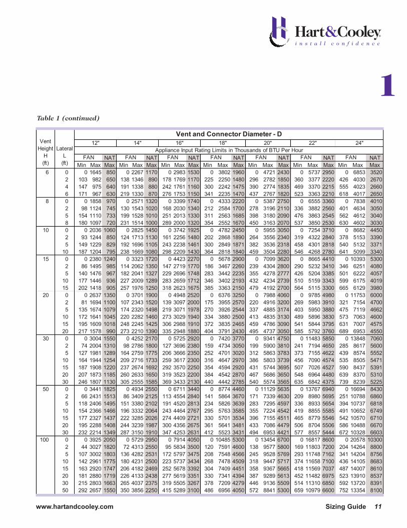
Appliance Input Rating Limits in Thousands of BTU Per Hour
FAN FAN FAN FAN FAN FAN FAN
Vent
Height
H
(ft)
Lateral
L
(ft)
Vent and Connector Diameter - D
12" 14" 16" 18" 20" 22" 24"
Table 1 (continued)

12 Sizing Guide www.hartandcooley.com
Type B Double-Wall Gas Vent Capacitieswith Single-Wall Connector
Single Category I Appliance
NAT NAT NAT NAT NAT NAT NAT NAT
Min Max Max Min Max Max Min Max Max Min Max Max Min Max Max Min Max Max Min Max Max Min Max Max
6 0 38 77 45 59 151 85 85 249 140 126 373 204 165 522 284 211 695 369 371 1118 569 537 1639 849
2 39 51 36 60 96 66 85 156 104 123 231 156 159 320 213 201 423 284 347 673 453 498 979 648
4 NA NA 33 74 92 63 102 152 102 146 225 152 187 313 208 237 416 277 409 664 443 584 971 638
6 NA NA 31 83 89 60 114 147 99 163 220 148 207 307 203 263 409 271 449 656 433 638 962 627
8 0 37 83 50 58 164 93 83 273 154 123 412 234 161 580 319 206 777 414 360 1257 658 521 1852 967
2 39 56 39 59 108 75 83 176 119 121 261 179 155 363 246 197 482 321 339 768 513 486 1220 743
5 NA NA 37 77 102 69 107 168 114 151 252 171 193 352 235 245 470 311 418 754 500 598 1104 730
8 NA NA 33 90 95 64 122 161 107 175 243 163 223 342 225 280 458 300 470 740 486 665 1089 715
10 0 37 87 53 57 174 99 82 293 165 120 444 254 158 628 344 202 844 449 351 1373 718 507 2031 1057
2 39 61 41 59 117 80 82 193 128 119 287 194 153 400 272 193 531 354 332 849 559 475 1242 848
5 52 56 39 76 111 76 105 185 122 148 277 186 190 388 261 241 518 344 409 834 544 584 1224 825
10 NA NA 34 97 100 68 132 171 112 188 261 171 237 369 241 296 497 325 492 808 520 688 1194 788
15 0 36 93 57 56 190 111 80 325 186 116 499 283 153 713 388 195 966 523 336 1591 838 488 2374 1237
2 38 69 47 57 136 93 80 225 149 115 337 224 148 473 314 187 631 413 319 1015 673 457 1491 983
5 51 63 44 75 128 86 102 216 140 144 326 217 182 459 298 231 616 400 392 997 657 562 1469 963
10 NA NA 39 95 116 79 128 201 131 182 308 203 228 438 284 284 582 381 470 966 628 664 1433 928
15 NA NA NA NA NA 72 158 186 124 220 290 192 272 418 269 334 568 367 540 937 601 750 1399 894
20 0 35 96 60 54 200 118 76 346 201 114 537 306 149 772 428 190 1053 573 326 1751 927 473 2631 1346
2 37 74 50 56 148 99 78 248 165 113 375 248 144 528 344 182 708 468 309 1146 754 443 1689 1098
5 50 68 47 73 140 94 100 239 158 141 363 239 178 514 334 224 692 457 381 1126 734 547 1665 1074
10 NA NA 41 93 129 86 125 223 146 177 344 224 222 491 316 277 666 437 457 1092 702 646 1626 1037
15 NA NA NA NA NA 80 155 208 136 216 325 210 264 469 301 325 640 419 526 1060 677 730 1587 1005
20 NA NA NA NA NA NA 186 192 126 254 306 196 309 448 285 374 616 400 592 1028 651 808 1550 973
30 0 34 99 63 53 211 127 76 372 219 110 584 334 144 849 472 184 1168 647 312 1971 1056 454 2996 1545
2 37 80 56 55 164 111 76 281 183 109 429 279 139 610 392 175 823 533 296 1346 863 424 1999 1308
5 49 74 52 72 157 106 98 271 173 136 417 271 171 595 382 215 806 521 366 1324 846 524 1971 1283
10 NA NA NA 91 144 98 122 255 168 171 397 257 213 570 367 265 777 501 440 1287 821 620 1927 1243
15 NA NA NA 115 131 NA 151 239 157 208 377 242 255 547 349 312 750 481 507 1251 794 702 1884 1205
20 NA NA NA NA NA NA 181 223 NA 246 357 228 298 524 333 360 723 461 570 1216 768 780 1841 1166
30 NA NA NA NA NA NA NA NA NA NA NA NA 389 477 305 461 670 426 704 1147 720 937 1759 1101
50 0 33 99 66 51 213 133 73 394 230 105 629 361 138 928 515 176 1292 704 295 2223 1189 428 3432 1818
2 36 84 61 53 181 121 73 318 205 104 495 312 133 712 443 168 971 613 280 1615 1007 401 2426 1509
5 48 80 NA 70 174 117 94 308 198 131 482 305 164 696 435 204 953 602 347 1591 991 496 2396 1490
10 NA NA NA 89 160 NA 118 292 186 162 461 292 203 671 420 253 923 583 418 1551 963 589 2347 1455
15 NA NA NA 112 148 NA 145 275 174 199 441 280 244 646 405 299 894 562 481 1512 934 668 2299 1421
20 NA NA NA NA NA NA 176 257 NA 236 420 267 285 622 389 345 866 543 544 1473 906 741 2251 1387
30 NA NA NA NA NA NA NA NA NA 315 376 NA 373 573 NA 442 809 502 674 1399 848 892 2159 1318
100 0 NA NA NA 49 214 NA 69 403 NA 100 659 395 131 991 555 166 1404 765 273 2479 1300 395 3912 2042
2 NA NA NA 51 192 NA 70 351 NA 98 583 373 125 828 508 158 1152 698 259 1970 1168 371 3021 1817
5 NA NA NA 67 186 NA 90 342 NA 125 551 366 156 813 501 194 1134 688 322 1945 1153 460 2990 1796
10 NA NA NA 85 175 NA 113 324 NA 153 532 354 191 789 486 238 1104 672 386 1905 1133 547 2938 1763
15 NA NA NA 132 162 NA 138 310 NA 188 511 343 230 674 473 281 1075 656 447 1865 1110 618 2888 1730
20 NA NA NA NA NA NA 168 295 NA 224 487 NA 270 739 458 325 1046 639 507 1825 1087 690 2838 1696
30 NA NA NA NA NA NA 231 264 NA 301 448 NA 355 685 NA 418 988 NA 631 1747 1041 834 2739 1627
50 NA NA NA NA NA NA NA NA NA NA NA NA 540 584 NA 617 866 NA 895 1591 NA 1138 2547 1489
12"
FAN
Vent and Connector Diameter - D
Appliance Input Rating Limits in Thousands of BTU Per Hour
FAN FAN FAN FAN FAN FAN FAN
Vent
Height
H
(ft)
Lateral
L
(ft)
3" 4" 5" 6" 7" 8" 10"
Table 2

www.hartandcooley.com Sizing Guide 13
Multiple-Appliance Vent Systems
How to Determine Each Vent Connector Size(Table 4A or 5A, pages 14-16)
• Determine the MINIMUM TOTAL VENT HEIGHT forthe system from a sketch of the proposed system.
• Determine the CONNECTOR RISE for eachappliance.
• Enter the VENT CONNECTOR Table 4A or 5A at theline showing VENT HEIGHT equal to or less thanthat determined above. Continue horizontally onthat line for the first appliance CONNECTOR RISEusing the appliance nameplate BTUH rating (sealevel). Always use a Table entry that equals orexceeds a draft-hood appliance input or that bracketsa fan-assisted appliance input. Read the connector vent size for that appliance at the top of the column.
• Using the same VENT HEIGHT, repeat the procedurefor each appliance, using its CONNECTOR RISE ANDBTUH rating.
CAUTION. NEVER use a connector size smaller thanthe draft-hood outlet size. (Exception: Does not applyto fan-assisted appliances.)
How to Determine Common Vent Size(Table 4B or 5B, pages 14-16)
• Total all appliance BTUH input ratings that are to beconnected to this common vent.
• Enter the COMMON VENT TABLE 4B or 5B at thesame VENT HEIGHT used to determine the ventconnector sizes above.
• Move horizontally across from this VENT HEIGHTfigure using either the L line if the common vent has anoffset, or has a horizontal manifold (Figure 4D), or theV line if the common vent is vertical with no offsets.
• Select the first value in the correct appliancecombination column that is equal to or greater thanthe total of BTUH ratings.
• The size of the required COMMON VENT is found atthe top of this column.
CAUTION. Regardless of the COMMON VENT sizedetermined by the above procedure, the vent MUST beat least as large as the largest connector. If more thanone connector is this same size, then use a COMMONVENT one size larger.
ExampleConnect a 45,000 BTU water heater with a draft hoodand 1-foot connector rise with a 100,000 BTU fan-equipped furnace with a 2-foot connector rise to aCommon Vent with a Minimum Total Vent Height of18 feet (Figure 6). All portions of the system areType B GAS VENT.
Water Heater Vent Connector SizeUse Vent Connector Table 4A under NAT. Read downMinimum Total Vent Height column to 15 feet and readacross 1 foot connector rise line to BTU rating equal toor higher than water heater input rating. This figureshows 53,000 BTU and is in the column for 4-inch connector. Since this is in excess of the water heaterinput, it is not necessary to find the maximum input for an 18-foot minimum total vent height. Use a 4-inchconnector (Figure 6A).
Furnace Vent ConnectorUse Vent Connector Table 4A. Read down Total VentHeight column to 15 feet and read across 2-footConnector Rise line to fan column. Note 4-inch ventsize shows 96,000 BTU per hour or less than furnaceinput. However, with 20-foot Total Height, read across2-foot connector rise line. Note 4-inch vent size shows105,000 BTU per hour. Since 18-foot height is 3/5 ofthis: 3/5(105,000 - 96,000) = 5400. 96,000 + 5400 =101,400, which is the maximum input for 18-footMinimum Total Vent Height. Therefore a 4-inchconnector would be the correct size for furnace,providing the furnace had a 4-inch or smaller drafthood outlet (Figure 6B).
Common Vent SizeTotal input to Common Vent is 145,000 BTU. Ventgoes straight through roof so use V line of Table 4Bunder FAN + NAT column. Note that for 15-footMinimum Total Vent Height maximum BTU for 5-inchvent is 164,000, which is greater than total input to thecommon vent. Therefore the common vent can be5-inch diameter (Figure 6C).
Figure 6
A.
B.
C.
ONE-FOOTCONNECTOR
RISEINTERCONNECTIONTEE
TWO-FEET CONNECTOR RISE
145,000 TOTAL INPUTCOMMON VENT5-INCH SIZE
18 FEETMINIMUM
TOTAL VENTHEIGHT
18 FEETMINIMUM
TOTAL VENTHEIGHT
18 FEETMINIMUM
TOTAL VENTHEIGHT
WATERHEATER45,000
WATERHEATER45,000
WATERHEATER45,000
4-INCHSIZE
4-INCHSIZE
FURNACE100,000
FURNACE100,000
FURNACE100,000
1

Type B Vent Connector CapacitiesFor Multiple Category I Appliances Connected to a Common Vent
NAT NAT NAT NAT NAT NAT NATMin Max Max Min Max Max Min Max Max Min Max Max Min Max Max Min Max Max Min Max Max
6 1 22 37 26 35 66 46 46 106 72 58 164 104 77 225 142 82 296 185 128 466 2892 23 41 31 37 75 55 48 121 86 60 183 124 79 253 168 95 333 220 131 526 3453 24 44 35 38 81 62 49 132 96 62 199 139 82 275 189 97 363 248 134 575 386
8 1 22 40 27 35 72 48 49 114 76 64 176 109 84 243 148 100 320 194 138 507 3032 23 44 32 36 80 57 51 128 90 66 195 129 86 269 175 103 356 230 141 564 3583 24 47 36 37 87 64 53 139 101 67 210 145 88 290 198 105 384 258 143 612 402
10 1 22 43 28 34 78 50 49 123 78 65 189 113 89 257 154 106 341 200 146 542 3142 23 47 33 36 86 59 51 136 93 67 206 134 91 282 182 109 374 238 149 596 3723 24 50 37 37 92 67 52 146 104 69 220 150 94 303 205 111 402 268 152 642 417
15 1 21 50 30 33 89 53 47 142 83 64 220 120 88 298 163 110 389 214 162 609 3332 22 53 35 35 96 63 49 153 99 66 235 142 91 320 193 112 419 253 165 658 3943 24 55 40 36 102 71 51 163 111 68 248 160 93 339 218 115 445 286 167 700 444
20 1 21 54 31 33 99 56 46 157 87 62 246 125 86 334 171 107 436 224 158 681 3472 22 57 37 34 105 66 48 167 104 64 259 149 89 354 202 110 463 265 161 725 4143 23 60 42 35 110 74 50 176 116 66 271 168 91 371 228 113 486 300 164 764 466
30 1 20 62 33 31 113 59 45 181 93 60 288 134 83 391 182 103 512 238 151 802 3722 21 64 39 33 118 70 47 190 110 62 299 158 85 408 215 105 535 282 155 840 4393 22 66 44 34 123 79 48 198 124 64 309 178 88 423 242 108 555 317 158 874 494
50 1 19 71 36 30 133 64 43 216 101 57 349 145 78 477 197 97 627 257 144 984 4032 21 73 43 32 137 76 45 223 119 59 358 172 81 490 234 100 645 306 148 1014 4783 22 75 48 33 141 86 46 229 134 61 366 194 83 502 263 103 661 343 151 1043 538
100 1 18 82 37 28 158 66 40 262 104 53 442 150 73 611 204 91 810 266 135 1285 4172 19 83 44 30 161 79 42 267 123 55 447 178 75 619 242 94 822 316 139 1306 4943 20 84 50 31 163 89 44 272 138 57 452 200 78 627 272 97 834 355 142 1327 555
Appliance Input Rating Limits in Thousands of BTU Per HourFAN FAN FAN FAN FAN FAN FAN
Vent
Height
H
(ft)
Connector
Rise
R
(ft)
Vent Connector Diameter - D
3" 4" 5" 6" 7" 8" 10"
Table 4A
Type B Common Vent CapacitiesWhen Using Type B Connectors
FAN FAN NAT FAN FAN NAT FAN FAN NAT FAN FAN NAT FAN FAN NAT FAN FAN NAT+FAN +NAT +NAT +FAN +NAT +NAT +FAN +NAT +NAT +FAN +NAT +NAT +FAN +NAT +NAT +FAN +NAT +NAT
6 L 74 65 52 112 93 82 163 129 117 247 198 160 323 251 210 538 416 328V 92 81 65 140 116 103 204 161 147 309 248 200 404 314 260 672 520 410
8 L 81 72 58 124 103 91 179 142 130 271 220 178 355 278 230 592 462 372V 101 90 73 155 129 114 224 178 163 339 275 223 444 348 290 740 577 465
10 L 88 78 63 135 113 98 194 155 142 294 239 193 382 302 250 640 502 396V 110 97 79 169 141 124 243 194 178 367 299 242 477 377 315 800 627 495
15 L 100 90 73 156 131 114 226 182 164 342 282 224 445 355 290 739 586 452V 125 112 91 195 164 144 283 228 206 427 352 280 556 444 365 924 733 565
20 L 109 98 81 172 146 127 251 204 182 380 315 250 497 399 325 828 661 512V 136 123 102 215 183 160 314 255 229 475 394 310 621 499 405 1035 826 640
30 L 122 110 94 195 168 147 289 238 211 438 367 290 576 468 375 967 780 592V 152 138 118 244 210 185 361 297 266 547 459 360 720 585 470 1209 975 740
50 L 134 122 107 223 195 171 337 282 248 513 438 338 683 565 440 1161 950 688V 167 153 134 279 244 214 421 353 310 641 547 423 854 706 550 1451 1188 860
100 L 140 130 NA 249 222 NA 391 337 NA 601 526 383 820 698 500 1427 1202 780V 175 163 NA 311 277 NA 489 421 NA 751 658 479 1025 873 625 1784 1502 975
Combined Appliance Input Rating in Thousands of BTU Per Hour
Vent
Height
H
(ft)
Vent
Type
Vent Connector Diameter - D
4" 5" 6" 7" 8" 10"
Table 4B
14 Sizing Guide www.hartandcooley.com

www.hartandcooley.com Sizing Guide 15
1NAT NAT NAT NAT NAT NAT NAT
Min Max Max Min Max Max Min Max Max Min Max Max Min Max Max Min Max Max Min Max Max6 2 174 764 496 223 1046 653 281 1371 853 346 1772 1080 NA NA NA NA NA NA NA NA NA
4 180 897 616 230 1231 827 287 1617 1081 352 2069 1370 NA NA NA NA NA NA NA NA NA6 NA NA NA NA NA NA NA NA NA NA NA NA NA NA NA NA NA NA NA NA NA
8 2 186 822 516 238 1126 696 298 1478 910 365 1920 1150 NA NA NA NA NA NA NA NA NA4 192 952 644 244 1307 884 305 1719 1150 372 2211 1460 471 2737 1800 560 3319 2180 662 3957 25906 198 1050 772 252 1445 1072 313 1902 1390 380 2434 1770 478 3018 2180 568 3665 2640 669 4373 3130
10 2 196 870 536 249 1195 730 311 1570 955 379 2049 1205 NA NA NA NA NA NA NA NA NA4 201 997 664 256 1371 924 318 1804 1205 387 2332 1535 486 2887 1890 581 3502 2280 686 4175 27106 207 1095 792 263 1509 1118 325 1989 1455 395 2556 1865 494 3169 2290 589 3849 2760 694 4593 3270
15 2 214 967 568 272 1334 790 336 1760 1030 408 2317 1305 NA NA NA NA NA NA NA NA NA4 221 1085 712 279 1499 1006 344 1978 1320 416 2579 1665 523 3197 2060 624 3881 2490 734 4631 29606 228 1181 856 286 1632 1222 351 2157 1610 424 2796 2025 533 3470 2510 634 4216 3030 743 5035 3600
20 2 223 1051 596 291 1443 840 357 1911 1095 430 2533 1385 NA NA NA NA NA NA NA NA NA4 230 1162 748 298 1597 1064 365 2116 1395 438 2778 1765 554 3447 2180 661 4190 2630 772 5005 31306 237 1253 900 307 1726 1288 373 2287 1695 450 2984 2145 567 3708 2650 671 4511 3190 785 5392 3790
30 2 216 1217 632 286 1664 910 367 2183 1190 461 2891 1540 NA NA NA NA NA NA NA NA NA4 223 1316 792 294 1802 1160 376 2366 1510 474 3110 1920 619 3840 2365 728 4681 2860 847 5606 34106 231 1400 952 303 1920 1410 384 2524 1830 485 3299 2340 632 4080 2875 741 4976 3480 860 5961 4150
50 2 206 1479 689 273 2023 1007 350 2659 1315 435 3548 1665 NA NA NA NA NA NA NA NA NA4 213 1561 860 281 2139 1291 359 2814 1685 447 3730 2135 580 4601 2633 709 5569 3185 851 6633 37906 221 1631 1031 290 2242 1575 369 2951 2055 461 3893 2605 594 4808 3208 724 5826 3885 867 6943 4620
100 2 192 1923 712 254 2644 1050 326 3490 1370 402 4707 1740 NA NA NA NA NA NA NA NA NA4 200 1984 888 263 2731 1346 336 3606 1760 414 4842 2220 523 5982 2750 639 7254 3330 769 8650 39506 208 2035 1064 272 2811 1642 346 3714 2150 426 4968 2700 539 6143 3350 654 7453 4070 786 8892 4810
Appliance Input Rating Limits in Thousands of BTU Per HourFAN FAN FAN FAN FAN FAN FAN
Vent
Height
H
(ft)
Connector
Rise
R
(ft)
Vent Connector Diameter - D
12" 14" 16" 18" 20" 22" 24"
Table 4A (continued)
FAN FAN NAT FAN FAN NAT FAN FAN NAT FAN FAN NAT FAN FAN NAT FAN FAN NAT FAN FAN NAT
+FAN +NAT +NAT +FAN +NAT +NAT +FAN +NAT +NAT +FAN +NAT +NAT +FAN +NAT +NAT +FAN +NAT +NAT +FAN +NAT +NAT
6 L 720 557 470 1027 792 652 1388 1069 825 1802 1386 1076 2270 1744 1328 2790 2142 1576 3365 2581 1912V 900 696 588 1284 990 815 1735 1336 1065 2253 1732 1345 2838 2180 1660 3488 2677 1970 4206 3226 2390
8 L 795 618 522 1138 882 730 1542 1193 952 2006 1549 1208 2530 1951 1488 3112 2398 1760 3756 2893 2144V 994 773 652 1423 1103 912 1927 1491 1190 2507 1936 1510 3162 2439 1860 3890 2998 2200 4695 3616 2680
10 L 861 673 570 1234 960 796 1674 1300 1040 2182 1690 1316 2755 2132 1624 3393 2622 1920 4098 3166 2336V 1076 841 712 1542 1200 995 2093 1625 1300 2727 2113 1645 3444 2665 2030 4241 3278 2400 5123 3957 2920
15 L 998 789 660 1435 1128 926 1952 1528 1208 2547 1987 1525 3221 2506 1888 3977 3090 2232 4813 3736 2720V 1247 986 825 1794 1410 1158 2440 1910 1510 3184 2484 1910 4026 3133 2360 4971 3862 2790 6016 4670 3400
20 L 1124 893 733 1605 1270 1032 2178 1718 1352 2849 2238 1712 3638 2842 2112 4458 3482 2496 5399 4209 3040V 1405 1116 916 2006 1588 1290 2722 2147 1690 3561 2798 2140 4548 3552 2640 5573 4352 3120 6749 5261 3800
30 L 1326 1062 820 1898 1514 1220 2576 2046 1592 3358 2661 2016 4242 3354 2488 5231 4126 2944 6352 4998 3584V 1658 1327 1025 2373 1892 1525 3220 2558 1990 4197 3326 2520 5303 4193 3110 6539 5157 3680 7940 6247 4480
50 L 1619 1312 1024 2329 1878 1490 3171 2546 1944 4147 3319 2460 5254 4192 3040 6493 5166 3600 7870 6250 4380V 2024 1640 1280 2911 2347 1836 3964 3183 2430 5184 4149 3075 6567 5240 3800 8116 6458 4500 9837 7813 5475
100 L 2055 1705 1336 2986 2461 1960 4100 3362 2560 5399 4407 3240 6878 5589 4000 8545 6918 4736 10403 8399 5760V 2569 2131 1670 3732 3076 2450 5125 4202 3200 6749 5509 4050 8597 6986 5000 10681 8648 5920 13004 10499 7200
Vent
Height
H
(ft)
Vent
Type
12" 14" 22" 24"
Vent Connector Diameter - D
Combined Appliance Input Rating in Thousands of BTU Per Hour16" 18" 20"
Table 4B (continued

16 Sizing Guide www.hartandcooley.com
Single-Wall Vent Connector CapacitiesFor Multiple Category I Appliances Connected to a Common Vent
NAT NAT NAT NAT NAT NAT NATMin Max Max Min Max Max Min Max Max Min Max Max Min Max Max Min Max Max Min Max Max
6 1 NA NA 26 NA NA 46 NA NA 71 NA NA 102 207 223 140 262 293 183 447 463 2862 NA NA 31 NA NA 55 NA NA 85 168 182 123 215 251 167 271 331 219 458 524 3443 NA NA 34 NA NA 62 121 131 95 175 198 138 222 273 188 279 361 247 468 574 385
8 1 NA NA 27 NA NA 48 NA NA 75 NA NA 106 226 240 145 285 316 191 481 502 2992 NA NA 32 NA NA 57 125 126 89 184 193 127 234 266 173 293 353 228 492 560 3553 NA NA 35 NA NA 64 130 138 100 191 208 144 241 287 197 302 381 256 501 609 400
10 1 NA NA 28 NA NA 50 119 121 77 182 186 110 240 253 150 302 335 196 506 534 3082 NA NA 33 84 85 59 124 134 91 189 203 132 248 278 183 311 369 235 517 589 3683 NA NA 36 89 91 67 129 144 102 197 217 148 257 299 203 320 398 265 528 637 413
15 1 NA NA 29 79 87 52 116 138 81 177 214 116 238 291 158 312 380 208 556 596 3242 NA NA 34 83 94 62 121 150 97 185 230 138 246 314 189 321 411 248 568 646 3873 NA NA 39 87 100 70 127 160 109 193 243 157 255 333 215 331 438 281 579 690 437
20 1 49 52 30 78 97 54 115 152 84 175 238 120 233 325 165 306 425 217 546 664 3362 52 55 36 82 103 64 120 163 101 182 252 144 243 346 197 317 453 259 558 709 4033 55 58 40 87 107 72 125 172 113 190 264 174 252 363 223 326 476 294 570 750 457
30 1 47 60 31 77 110 57 112 175 89 169 278 129 226 380 175 296 497 230 528 779 3582 51 62 37 81 115 67 117 185 106 177 290 152 236 397 208 307 521 274 541 819 4253 54 64 42 85 119 76 122 193 120 185 300 172 244 412 235 316 542 309 555 855 482
50 1 46 69 34 75 128 60 109 207 96 162 336 137 217 460 188 284 604 245 507 951 3842 49 71 40 79 132 72 114 215 113 170 345 164 226 473 223 294 623 293 520 983 4583 52 72 45 83 136 82 119 221 123 178 353 186 235 486 252 304 640 331 535 1013 518
100 1 45 79 34 71 150 61 104 249 98 153 424 140 205 585 192 269 774 249 476 1236 3932 48 80 41 75 153 73 110 255 115 160 428 167 212 593 228 279 788 299 490 1259 4693 51 81 46 79 157 85 114 260 129 168 433 190 222 603 256 289 801 339 506 1280 527
Appliance Input Rating Limits in Thousands of BTU Per HourFAN FAN FAN FAN FAN FAN FAN
Vent
Height
H
(ft)
Connector
Rise
R
(ft)
Vent Connector Diameter - D
3" 4" 5" 6" 7" 8" 10"
Table 5A Vent Connector Capacity
Type B Common Vent CapacitiesWhen Using Single-Wall Connectors
FAN FAN NAT FAN FAN NAT FAN FAN NAT FAN FAN NAT FAN FAN NAT FAN FAN NAT+FAN +NAT +NAT +FAN +NAT +NAT +FAN +NAT +NAT +FAN +NAT +NAT +FAN +NAT +NAT +FAN +NAT +NAT
6 L NA 62 51 NA 90 80 160 126 115 243 195 157 318 248 206 523 412 326V NA 78 64 NA 113 100 200 158 144 304 244 196 398 310 257 665 515 407
8 L NA 70 57 NA 101 90 174 138 127 265 215 174 349 274 228 584 455 368V NA 87 71 NA 126 112 218 173 159 331 269 218 436 342 285 730 569 460
10 L NA 75 61 130 110 96 190 151 139 286 234 189 374 295 247 630 494 390V NA 94 76 163 137 120 237 189 174 357 292 236 467 369 309 787 617 487
15 L 97 86 70 151 127 112 220 177 160 333 274 219 435 347 286 724 574 442V 121 108 88 189 159 140 275 221 200 416 343 274 544 434 357 905 718 553
20 L 105 94 78 166 142 124 244 198 178 370 306 242 485 390 316 810 646 501V 131 118 98 208 177 155 305 247 223 436 383 302 606 487 395 1013 808 626
30 L 116 106 90 189 162 143 280 229 206 426 357 279 562 456 367 946 762 578V 145 132 113 236 202 179 350 286 257 533 446 349 703 570 459 1183 952 723
50 L 127 116 102 214 186 163 325 270 237 498 423 328 666 549 428 1134 926 670V 159 145 128 268 233 204 406 337 296 622 529 410 833 686 535 1418 1157 838
100 L 133 122 NA 238 210 NA 375 318 NA 581 506 371 799 677 485 1393 1167 758V 166 153 NA 297 263 NA 469 398 NA 726 633 464 999 856 606 1741 1459 948
Vent
Height
H
(ft)
Vent
Type
Vent Connector Diameter - D
4" 5" 6" 7" 8" 10"Combined Appliance Input Rating in Thousands of BTU Per Hour
Table 5B Common Vent Capacity
www.hartandcooley.com Sizing Guide 17
Additional Guidelines for Multiple-Appliance Venting When common-venting, connector Tables 4A and 5Aallow for connector lateral lengths of 1½ feet(18 inches) for each inch of connector diameter asfollows:
Connector Lateral Length AllowanceDiameter 3" 4" 5" 6" 7" 8" 10" 12" 16" 24"Length, Ft. 4½ 6 7½ 9 10½ 12 15 18 24 36Table 3
It is permissible to double the length shown by reducingthe maximum connector capacity by 10%. Next,determine FAN MIN by using the corresponding single-appliance table treating each appliance and connectoralong with the common vent as a single-appliance ventsystem. If the input is still above FAN MIN, go aheadand double the connector length.
If the vent connectors are combined prior to enteringthe common vent (Figure 4D, page 7), the maximumcommon vent capacity shall be reduced by 10%. Thehorizontal length allowance shall not exceed 1½ feet(18 inches) for each inch of common vent manifolddiameter. This length limitation also includes thecommon vent offset in the attic added together.
When manifolding a fan-assisted appliance with a draft-hood-equipped appliance, the fan-assisted applianceshould be positioned closer to the common verticalvent.
If the common vent has a horizontal offset (Figure 4C,page 7), the maximum common vent capacity shall bereduced by 20%, the equivalent of two 90° elbows. This20% reduction is listed in the L line in Tables 4B and5B. The horizontal length of the common vent offsetshall not exceed 1½ feet for each inch of common ventdiameter. A 10% reduction in common vent capacitymust be taken for each additional 90° fitting.
The common vent diameter shall be at least as large asthe largest vent connector diameter.
Interpolation is permitted between table entries.Extrapolation beyond table entries is not permitted.
The “7 times rule” (page 9) also limits the size of thecommon vent to no more than 7 times the cross-sectional area of the smallest connected appliance ventconnector or flue collar area; do not use the connectorpipe area.
Additional Guidelines for Multiple-Appliance VentingUse available headroom for maximum connectorriseAlways use available headroom for maximumconnector rise after allowing for the listed clearanceto combustibles. Obtain maximum connector rise bysuch methods as extending the connectors between thefloor joists. Increased venting power and efficiency ofthe system permits reduction of vent and connectorsizes.
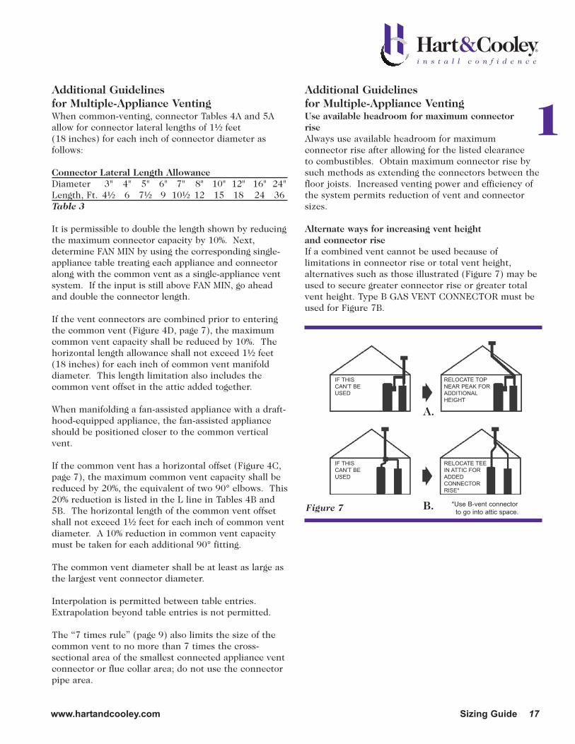
Alternate ways for increasing vent height and connector riseIf a combined vent cannot be used because oflimitations in connector rise or total vent height,alternatives such as those illustrated (Figure 7) may beused to secure greater connector rise or greater totalvent height. Type B GAS VENT CONNECTOR must beused for Figure 7B.
Figure 7
IF THIS
CAN’T BE
USED
IF THIS
CAN’T BE
USED
A.
B.
1
RELOCATE TOP
NEAR PEAK FOR
ADDITIONAL
HEIGHT
RELOCATE TEE
IN ATTIC FOR
ADDED
CONNECTOR
RISE*
*Use B-vent connector
to go into attic space.

18 Sizing Guide www.hartandcooley.com
Type B Double-Wall Gas Vents
The configurations of the vent connector are not asimportant as the connector rise and length require-ments being satisfactorily met. All of the illustratedmethods in Figure 8 permit correct vent operation.
For economy, consider all alternativesIt is important in a combined vent system that the costof individual versus combined vents be considered,especially if the system is short or many fittings areneeded.
Frequently, individual vents will prove more economical than a combined system in instances of this type (Figure 9).
Self-venting connectors sized from single-appliance vent tablesWhen a vent connector as a part of a combined ventsystem has a rise of 5 feet or more, it can be installed asthough it were an individual vent by using the appropri-ate Single-Appliance Vent Tables. It is important whensizing self-venting connectors that allowances be madefor lateral length and the number of turns.
When in doubt use one size larger ventIt is neither possible nor practical in some cases toanticipate all installation or operational contingenciesin designing a vent system. A safe rule is, when indoubt use one size larger connectors and commonvents than required by the Vent Tables.
Size of interconnecting teesInterconnecting tees must be the same size as thecommon vent, as shown in Figure 10.
Use of Manifolds
Use of Line V Capacities for Manifold SizingA manifold is merely a vent system that is a horizontalextension of the lower end of a common vent. The connection of a manifold to a common vent may bemade by either a 90° elbow or tee. A manifold should be sized as a common vent, using the combined totalcapacity and applicable total height of the vent system.The V lines in the common vent table must be reducedby 10% to determine the capacity of the manifold andcommon vent. There is also the horizontal lengthlimitation of 1.5 feet per inch of common vent thatmust be followed.
Horizontal Versus Sloped ManifoldsSome codes require pitched or sloped manifolds. Therequirements for sloped manifolds or connectors is anecessity for vent systems having low insulating valueswhere condensation may occur. Adequate connector riseis necessary for proper venting of all appliances; therefore,lateral manifolds should NOT be excessively sloped. Toomuch manifold slope may cause insufficient connectorrise at the appliance farthest from the common vent,increasing the chance of draft-hood spillage.
Figure 8
Figure 10
Figure 9
LEASTPREFERRED
MOSTPREFERRED
SHORT COMBINED VENTSMAY REQUIRE EXCESSIVEFITTINGS, EXTRA LARGECOMMON VENT
INDIVIDUAL VENTS CANPROVIDE BETTER VENTINGAT LESS COST
3-FT. RISE
3-FT. RISE 3-FT. RISE
SMALLTEE WRONG
MUST BESAME SIZE ASCOMMONVENT
CORRECT
TEE
INCORRECT
Manifold ConnectorsVent connectors from a group of appliances on onelevel may enter from below or from the side of themanifold. In either case, the connector rise should bemeasured as the vertical distance from the draft-hoodoutlet to the lowest level at which the connector entersthe manifold. Care must be exercised in designingthese systems, especially with connector turns andlengths, because heat loss is apt to be greater for suchsystems causing accompanying capacity reduction.
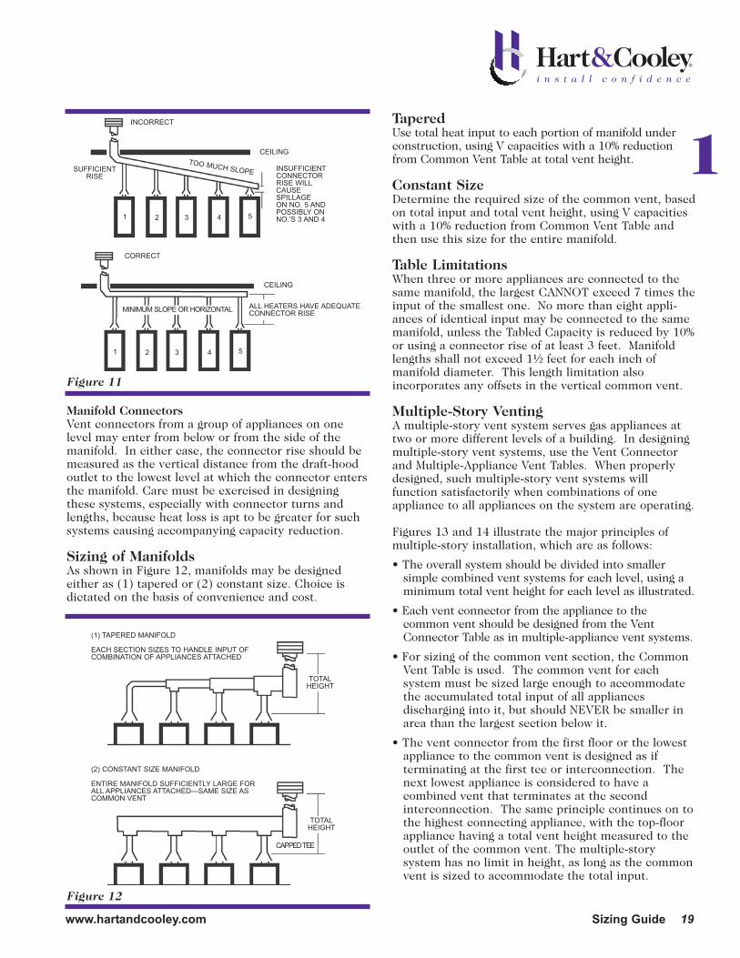
Sizing of ManifoldsAs shown in Figure 12, manifolds may be designedeither as (1) tapered or (2) constant size. Choice isdictated on the basis of convenience and cost.
TaperedUse total heat input to each portion of manifold underconstruction, using V capacities with a 10% reductionfrom Common Vent Table at total vent height.
Constant SizeDetermine the required size of the common vent, basedon total input and total vent height, using V capacitieswith a 10% reduction from Common Vent Table andthen use this size for the entire manifold.
Table LimitationsWhen three or more appliances are connected to thesame manifold, the largest CANNOT exceed 7 times theinput of the smallest one. No more than eight appli-ances of identical input may be connected to the samemanifold, unless the Tabled Capacity is reduced by 10%or using a connector rise of at least 3 feet. Manifoldlengths shall not exceed 1½ feet for each inch ofmanifold diameter. This length limitation alsoincorporates any offsets in the vertical common vent.
Multiple-Story VentingA multiple-story vent system serves gas appliances at two or more different levels of a building. In designingmultiple-story vent systems, use the Vent Connectorand Multiple-Appliance Vent Tables. When properlydesigned, such multiple-story vent systems willfunction satisfactorily when combinations of oneappliance to all appliances on the system are operating.
Figures 13 and 14 illustrate the major principles of multiple-story installation, which are as follows:
• The overall system should be divided into smaller simple combined vent systems for each level, using aminimum total vent height for each level as illustrated.
• Each vent connector from the appliance to thecommon vent should be designed from the VentConnector Table as in multiple-appliance vent systems.
• For sizing of the common vent section, the CommonVent Table is used. The common vent for eachsystem must be sized large enough to accommodatethe accumulated total input of all appliancesdischarging into it, but should NEVER be smaller inarea than the largest section below it.
• The vent connector from the first floor or the lowestappliance to the common vent is designed as ifterminating at the first tee or interconnection. Thenext lowest appliance is considered to have acombined vent that terminates at the secondinterconnection. The same principle continues on tothe highest connecting appliance, with the top-floorappliance having a total vent height measured to theoutlet of the common vent. The multiple-storysystem has no limit in height, as long as the commonvent is sized to accommodate the total input.
Figure 11
INSUFFICIENTCONNECTOR RISE WILLCAUSESPILLAGE ON NO. 5 ANDPOSSIBLY ONNO.’S 3 AND 4
ALL HEATERS HAVE ADEQUATECONNECTOR RISE
CEILING
1 2 3 4 5
1 2 3 4 5
CEILING
INCORRECT
CORRECT
MINIMUM SLOPE OR HORIZONTAL
SUFFICIENTRISE
Figure 12
TOTALHEIGHT
(1) TAPERED MANIFOLD
EACH SECTION SIZES TO HANDLE INPUT OFCOMBINATION OF APPLIANCES ATTACHED
(2) CONSTANT SIZE MANIFOLD
ENTIRE MANIFOLD SUFFICIENTLY LARGE FORALL APPLIANCES ATTACHED—SAME SIZE ASCOMMON VENT
TOTALHEIGHT
CAPPED TEE
TOO MUCH SLOPE 1
www.hartandcooley.com Sizing Guide 19
20 Sizing Guide www.hartandcooley.com
CAUTION: It is important to keep the followingpoints in mind.
• Common vent height must always be computed as the distance from the outlet of the connected appliance to the lowest part of the opening from the next interconnection above.
• If the connector rise is inadequate, increase connector size, always making sure of maximum available connector rise.
• Be sure that the air supply to each appliance is adequate for proper operation. A separation of appliance rooms from occupied areas and provision for outside air supply is necessary.
• If an air shaft is used for installation of the commonvent, be sure that sufficient space is provided for fittings, clearance to combustibles, and access for proper assembly.
• These calculations apply ONLY when the entire system is constructed of listed double-wall Type BVent materials.
Ratio of Connector Size to Common Vent SizeWhenever the area of the common vent becomes morethan 7 times the area of the vent connector entering it,the connector rise must be increased one foot above theallowable vent connector rise shown in the Tables. Forexample, where appliance input is 90,000 BTU per hourusing a 5-inch (area 20 square inches) vent connectorin a system having a minimum vent height of 10 feet,the vent connector rise must be 2 feet on the lowerfloors where the common vent size is 12 inches (area113 square inches) or less. However, as soon as a largercommon vent size is required, such as 14 inches (area154 square inches), the vent connector rise must beincreased to 3 feet to avoid draft hood spillage.
This requirement does NOT apply when the connector rise is originally over 5 feet andconsequently self-venting.
Offsets in Multistory VentsA multistory common vertical vent may have a single offset, provided:
A. The offset does not exceed 45°, and
B. The section of common vent that contains theoffset shall be reduced by 20%, and
C. The horizontal length of the offset does not exceed1½ feet for each inch of common vent diameter.
Economy of Parallel SystemsIt may frequently prove more economical to group appliances to upper and lower common vent systems sothat smaller vent sizes can be used. Even though manyappliances may be connected to a single multiple-storycommon vent, the increase in size caused by this mayprove uneconomical because of the space for accessrequired and the need for numerous fittings. Analternate procedure is to use parallel common ventswith staggered connections at alternate floors, therebygreatly increasing the minimum total vent heightavailable to each connected appliance.
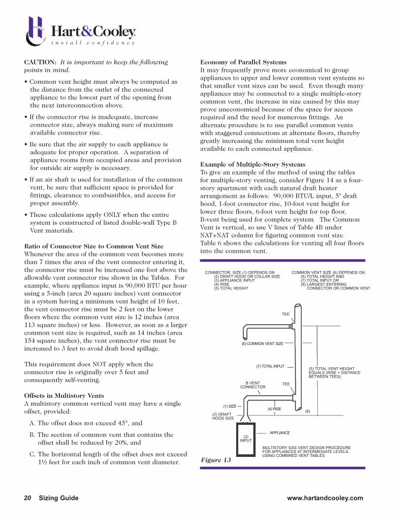
Example of Multiple-Story SystemsTo give an example of the method of using the tablesfor multiple-story venting, consider Figure 14 as a four-story apartment with each natural draft heaterarrangement as follows: 90,000 BTU/L input, 5" drafthood, 1-foot connector rise, 10-foot vent height forlower three floors, 6-foot vent height for top floor,B-vent being used for complete system. The CommonVent is vertical, so use V lines of Table 4B underNAT+NAT column for figuring common vent size.Table 6 shows the calculations for venting all four floorsinto the common vent.
Figure 13
CONNECTOR: SIZE (1) DEPENDS ON(2) DRAFT HOOD OR COLLAR SIZE(3) APPLIANCE INPUT(4) RISE(5) TOTAL HEIGHT
COMMON VENT SIZE (6) DEPENDS ON(5) TOTAL HEIGHT AND(7) TOTAL INPUT OR(8) LARGEST ENTERING
CONNECTOR OR COMMON VENT
(5) TOTAL VENT HEIGHTEQUALS (RISE + DISTANCEBETWEEN TEES)
MULTISTORY GAS VENT DESIGN PROCEDUREFOR APPLIANCES AT INTERMEDIATE LEVELS,USING COMBINED VENT TABLES
(2) DRAFTHOOD SIZE
TEE
TEE
(8)
(6) COMMON VENT SIZE
(1) SIZE (4) RISE
(3)INPUT
(7) TOTAL INPUT
APPLIANCE
B VENTCONNECTOR

www.hartandcooley.com Sizing Guide 21
1
Figure 14
USE INDIVIDUAL VENT FORTOP-FLOOR APPLIANCE IFCONNECTOR REQUIREMENTFOR RISE OR TOTAL HEIGHTCANNOT BE MET (Table 1 or 2)
USE CONNECTOR DESIGNTABLE (Table 4A or 5A)
TOP-FLOOR APPLIANCE
USE CONNECTOR DESIGNTABLE (Table 4A or 5A)
THIRD-FLOOR APPLIANCE
USE CONNECTOR DESIGNTABLE (Table 4A or 5A)
SECOND-FLOOR APPLIANCE
FIRST-FLOOR APPLIANCE
APPROVED TOP
USE TOTAL HEIGHT FOR TOP-FLOORAPPLIANCE AND COMBINED INPUTOF ALL APPLIANCES ON COMMONVENT (Table 4B or5B)
THIRD INTERCONNECTION TEE*
USE TOTAL HEIGHT FOR THIRD-FLOOR APPLIANCE AND COMBINEDINPUT OF THREE APPLIANCES; IFTOP-FLOOR APPLIANCE IS NOTCONNECTED, MEASURE TOTALHEIGHT TO VENT TOP (Table 4B or 5B)
SECOND INTERCONNECTION TEE*
USE TOTAL HEIGHT FOR SECOND-FLOOR APPLIANCE AND COMBINEDHEAT INPUT OF TWO APPLIANCES(Table 4B or 5B)
FIRST INTERCONNECTION TEE*
DESIGN CONNECTOR FORFIRST-FLOOR APPLIANCE AS ANINDIVIDUAL VENT OF THIS TOTALHEIGHT, FOR INPUT OF FIRST-FLOOR APPLIANCE (Table 1 or 2)
*EACH INTERCONNECTION TEE IS THE SAME SIZE ASPORTION OF COMMON VENT DIRECTLY ABOVE.
PRINCIPLES OF DESIGN OF MULTISTORY VENTS USINGVENT CONNECTOR AND COMMON VENT DESIGN TABLES
TEE WITH CAP OPTIONAL
TOTALHEIGHT FORTOP-FLOORAPPLIANCE
TOTALHEIGHT FOR
THIRD-FLOORAPPLIANCE
TOTALHEIGHT FOR
SECOND-FLOORAPPLIANCE
RISE
RISE
RISE
However, if the heater on the top floor is ventedseparately, Table 7 shows the result of increasing theMinimum Total Vent Height of the third-floor applianceto 16 feet and decreasing total input to the commonvent to 270,000 BTU per hour.
Table 7 indicates the economics of venting the top floorseparately, which eliminates the larger sizes of ventpipe and the use of costly increasing fittings.
Type B Double-Wall Gas VentsTable 6
Min.Input Available Total Common
Total BTUH Connector Vent Connector VentAppliance To Common Vent Rise Height Size Size
1 90,000 10' 10' 5" with up to 10' lateral self-venting connector
2 180,000 1' 10' 6" 7"3 270,000 1' 10' 6" 8"4 360,000 1' 6' 6" 10"

22 Sizing Guide www.hartandcooley.com
A. COMBUSTION AIR requirements MUST be suppliedfrom outside the living areas from sources such as hallways, service areas or outdoor balconies in accordance with the information in NFPA Standard 54 ANSI Z223.1. It is preferred that this air be takeninto the appliance room directly from outdoors. Thisis important because any restriction in the commonvent or termination will cause flue products of allappliances below this obstruction to spill out thedraft hoods of other appliances just below thisobstruction.
B. Other Cautions
1. Provide proper clearance to combustibles aroundthe common vent in its chase or shaft.
2. Use the highest connector rise possible. Ifcapacity is borderline, use the next size connector.
3. The only draft effect to be considered available is due to the vertical height from the draft-hoodrelief opening of the highest appliance on thatfloor to the point where the connector for the floorabove enters the common vent. NEVER USE THEHEIGHT TO THE TERMINATION except for thetop floor.
4. The appliance on the first floor is considered to beself-venting (vertical height 5 feet or more), andtherefore sizing is calculated using Table 2 Single-Appliance Venting.
Type B Double-Wall Gas Vents
Table 7
Min.
Input Available Total Common
Total BTUH Connector Vent Connector Vent
Appliance To Common Vent Rise Height Size Size
1 90,000 10' 10' 5" self-venting connector
2 180,000 1' 10' 6" 7"3 270,000 1' 16' 6" 7"4 90,000 6' 6' 5" self-venting connector
Special Considerations and Additional Precautions

Factory-BuiltAll-Fuel Chimney SystemsSizing Guide
2
23

Description
The Hart & Cooley® MODEL TLC all-fuel chimneysystem consists of straight sections and other necessaryfittings, which are constructed of stainless steel outerjacket and stainless steel inner liner spaced one inchsmaller to provide an enclosure for solid packinsulation. This chimney system may be fully enclosedby the structure when the minimum clearance airspaceof 2 inches is maintained to all materials of thestructure or contents—THIS MEANS NO INSULATIONIS TO BE WRAPPED OR PACKED AROUND THISCHIMNEY SYSTEM CLOSER THAN 2 INCHES,UNLESS USING INSULATION PROVIDED BYHART & COOLEY FOR SPECIFIC USES. Followinstallation instructions.
Appliances That May Be Connected
This system is to be used with all neutral or negativedraft gas, liquid, or solid fuel-fired residentialappliances and other building heating appliances thatproduce flue products up to 1000°F during normaloperation and up to 1400°F for up to one hour ofunusual firing, and to 2100°F for up to 10 minutes at atime.
This system is listed by Underwriters Laboratories ascomplying with Standard UL 103-HT. FOR PROPERINSTALLATION, READ AND FOLLOW THE INSTALLA-TION INSTRUCTIONS PACKED WITH PRODUCT.
Preliminary Planning
Check the local building code for additional installationrequirements for the area. The National FireProtection Association Standards 31 and 211 requirethat the chimney extend at least 3 feet above thehighest side of the roof opening through which thechimney passes AND at least 2 feet higher than anyportion of the building within a 10-foot horizontaldistance. See Figure 16.
• Make a sketch of the proposed chimney system.
Locate the chimney near the appliance, taking carethat all structural and other obstructions areconsidered. Measure and note horizontal and verticalsections to be needed plus all elbows and other fittings.
24 Sizing Guide www.hartandcooley.com
Model TLC All-Fuel Chimney System
Figure 16
Figure 17

www.hartandcooley.com Sizing Guide 25
2System
Height, Ft.
Lateral, Ft.
w/ (2) 90° turns
GPH for
6" dia
GPH for
5" dia
GPH for
4" dia
4 0.5-1.0 0.4-0.65 0.25
10 0.4-0.75 NR NR
4 0.65-1.25 0.4-0.75 0.4
10 0.5-1.0 0.4-0.75 0.4
4 0.65-1.5 0.5-0.85 0.4
10 0.65-1.25 0.65-0.85 0.4-0.5
4 0.75-1.5 0.65-1.0 0.5
10 0.85-1.25 0.65-0.85 0.5
4 1.0-1.75 0.75-1.0 0.5
10 1.0-1.5 0.75-1.0 0.5
4 1.25-1.75 0.85-1.0 0.65
10 1.25-1.75 0.85-1.0 0.65
System
Height, Ft.
Lateral, Ft.
w/ (2) 90° turns
GPH for
6" dia
GPH for
5" dia
GPH for
4" dia
4 0.4-1.25 0.4-0.85 0.25-0.5
10 0.4-1.25 0.4-0.75 0.25
4 0.5-1.5 0.4-1.0 0.4-0.5
10 0.5-1.25 0.4-0.85 0.4-0.5
4 0.65-1.75 0.5-1.0 0.4-0.5
10 0.65-1.5 0.5-1.0 0.4-0.5
4 0.75-1.75 0.5-1.0 0.4-0.5
10 0.75-1.75 0.65-1.0 0.4-0.5
4 0.85-2.0 0.65-1.25 0.5-0.65
10 0.85-2.0 0.65-1.25 0.5-0.65
4 1.0-2.25 0.75-1.25 0.65-0.75
10 1.0-2.0 0.85-1.25 0.65-0.75
Chimney Sizing for 88% Steady State Appliances (10-14% CO2, 300°F gross)
10
15
20
25
35
40
Chimney Sizing for 86% Steady State Appliances (10-14% CO2, 370°F gross)
35
40
GPH (gallons per hour firing rate) * 140,000 = BTU/hr input
NR: Not recommended
Flexible liners: reduce max GPH by 15% due to higher flow losses
Calculations based from draft set at -0.03" of water at appliance outlet
10
15
20
25
GPH (gallons per hour firing rate) * 140,000 = BTU/hr input
NR: Not recommended
Flexible liners: reduce max GPH by 15% due to higher flow losses
Calculations based from draft set at -0.03" of water at appliance outlet
System
Height, Ft.
Lateral, Ft.
w/ (2) 90° turns
GPH for
6" dia
GPH for
5" dia
GPH for
4" dia
4 0.4-1.5 0.25-1.0 0.25-0.5
10 0.4-1.5 0.25-0.85 0.25-0.5
4 0.4-1.75 0.4-1.25 0.25-0.65
10 0.4-1.75 0.4-1.0 0.25-0.65
4 0.5-2.0 0.4-1.25 0.4-0.75
10 0.5-2.0 0.4-1.25 0.4-0.75
4 0.5-2.25 0.5-1.5 0.4-0.75
10 0.65-2.0 0.5-1.25 0.4-0.75
4 0.65-2.25 0.65-1.5 0.5-0.85
10 0.75-2.25 0.65-1.5 0.5-0.85
4 0.75-2.25 0.75-1.5 0.5-0.85
10 0.85-2.25 0.75-1.5 0.5-0.85
System
Height, Ft.
Lateral, Ft.
w/ (2) 90° turns
GPH for
6" dia
GPH for
5" dia
GPH for
4" dia
4 0.25-1.75 0.25-1.0 0.25-0.65
10 0.4-1.5 0.25-1.0 0.25-0.65
4 0.4-2.0 0.4-1.25 0.25-0.75
10 0.5-2.0 0.4-1.25 0.25-0.75
4 0.4-2.25 0.4-1.5 0.4-0.85
10 0.4-2.0 0.4-1.25 0.4-0.75
4 0.4-2.25 0.4-1.5 0.4-0.85
10 0.65-2.25 0.5-1.5 0.4-0.85
4 0.5-2.25 0.5-1.75 0.4-0.85
10 0.65-2.25 0.65-1.5 0.4-0.85
4 0.65-2.25 0.65-1.75 0.5-1.5
10 0.65-2.25 0.65-1.75 0.5-0.85
Chimney Sizing for 82% Steady State Appliances (10-14% CO2, 505°F gross)
10
15
20
25
35
40
GPH (gallons per hour firing rate) * 140,000 = BTU/hr input
NR: Not recommended
Flexible liners: reduce max GPH by 15% due to higher flow losses
Calculations based from draft set at -0.03" of water at appliance outlet
Chimney Sizing for 80% Steady State Appliances (10-14% CO2, 575°F gross)
10
40
GPH (gallons per hour firing rate) * 140,000 = BTU/hr input
NR: Not recommended
Flexible liners: reduce max GPH by 15% due to higher flow losses
Calculations based from draft set at -0.03" of water at appliance outlet
15
20
25
35
Oil-Fired Appliance Chimney Sizing(Tables based on steady state efficiency. Content from NFPA 31, 2006 Edition.)
Determining steady state efficiency by AFUE:
- Add 1% to AFUE for hydronic boiler.- Add 2% to AFUE for warm-air furnace.
System
Height, Ft.
Lateral, Ft.
w/ (2) 90° turns
GPH for
6" dia
GPH for
5" dia
GPH for
4" dia
4 0.4-1.5 0.25-0.85 0.25-0.5
10 0.4-1.25 0.25-0.85 0.25-0.4
4 0.5-1.75 0.4-1.0 0.25-0.65
10 0.65-1.5 0.4-1.0 0.4-0.5
4 0.65-1.75 0.5-1.25 0.4-0.65
10 0.65-1.75 0.5-1.0 0.4-0.5
4 0.65-2.0 0.5-1.25 0.4-0.75
10 0.65-2.0 0.5-1.25 0.4-0.65
4 0.85-2.25 0.65-1.5 0.5-0.75
10 0.85-2.25 0.65-1.25 0.5-0.75
4 1.0-2.25 0.75-1.5 0.65-0.75
10 1.0-2.25 0.75-1.5 0.65-0.75
20
Chimney Sizing for 84% Steady State Appliances (10-14% CO2, 440°F gross)
10
15
25
35
40
GPH (gallons per hour firing rate) * 140,000 = BTU/hr input
NR: Not recommended
Flexible liners: reduce max GPH by 15% due to higher flow losses
Calculations based from draft set at -0.03" of water at appliance outlet

26 Sizing Guide www.hartandcooley.com
*For EACH 90° turn (tee, elbow), ADD this value to Tabled Height figure to get ACTUAL vertical height required.
GPH x 140,000 = BTUH
Chimney Sizing for Appliances Using Table 9ExampleGIVEN:• Input is 700,000 BTUH.• Draft required is 0.04 inches w.c.• System contains one 90° elbow and one tee.• Collar size of appliance is 10 inches.
SOLUTION: Find Input 700 (thousand) BTUH in the leftcolumn and 0.04 inches w.c. draft at the top of the table.Adjacent to the Input column is a column giving multiple
choices of chimney sizes. For a trial, use the flue collar size of10 inches. Adjacent to the 10-inch size is a figure 3½, whichis explained as the feet that must be added for EACH 90°turn. Proceed to right from 700 figure, then the 10-inch sizehorizontally to the right until it intersects the 0.04 verticalcolumn. The height shown is 7 feet. There are two 90° turnsrequired (the 90° elbow and tee given); therefore, 7 feet mustbe added (2 times 3½) to the 7 feet given in the table. Therequired chimney height is then 14 feet (7+7). A larger sizechimney will result in a lower total height if such is required.
Table 9
0.04 0.05 0.06 0.07 0.08 0.09 0.10
6 1 6 7½ 9 10½ 12 13½ 15 7 1 5½ 7 8½ 10 11½ 12½ 14 8 1 5½ 7 8 9½ 11 12 13½6 2 6½ 8½ 10 11½ 13½ 15 16½7 1½ 6½ 8 9½ 11 12½ 14 16 8 1 6 7½ 9 10½ 12 13½ 15
10 1 6 7 8½ 10 11½ 13 14½6 4½ 7½ 9½ 11 12½ 15 16½ 18½7 3 7 8½ 10 12 13½ 15 17 8 1½ 6½ 8 9½ 11 13 14½ 16
10 1 6 7½ 9 10½ 12 13½ 15 7 4½ 7½ 9½ 11 12½ 15 16½ 18½8 3 7 8½ 10 12 13½ 15 17
10 1½ 6½ 8 9½ 11 13 14½ 16 12 1 6 7½ 9 10½ 12 13½ 15
8 4 7½ 9 11 12½ 14½ 16½ 18 10 2 6½ 8 9½ 11½ 13 14½ 16 12 1 6 7½ 9 10½ 12 13½ 15 14 1 6 7½ 8½ 10 11½ 13 14½10 2½ 7 8½ 10 12 13½ 16 17 12 1½ 6½ 8 9½ 11 12½ 14 15½14 1 6 7½ 9 10½ 12½ 14 15½10 3½ 7 9 10½ 12½ 14 16 17½12 1½ 6½ 8 9½ 11 13 14½ 16 14 1 6 7½ 9 10½ 12½ 14 15½10 4½ 7½ 9½ 11 13 14½ 16½ 18 12 2½ 7 8½ 10 11½ 13½ 15 16½14 1 6½ 8 9½ 11 12½ 14 15½12 3 7 8½ 10 12 14 15½ 17 14 2 6½ 8 9½ 11½ 13 14½ 16 12 3½ 7 9 10½ 12½ 14 16 17½14 2 6½ 8½ 9½ 11½ 13 14½ 16 12 4 7½ 9 10½ 12½ 14½ 16 18 14 2 6½ 8½ 10 11½ 13½ 15 16½12 4½ 7½ 9½ 11 13 15 16½ 18½14 2½ 7 8½ 10 12 13½ 15½ 17
1300 14 3 7 9 10½ 12 14 15½ 17½1400 14 3½ 7 9 10½ 12½ 14 16 17½1500 14 4 7½ 9 11 12½ 14½ 16½ 18
Chimney Sizing for Lower Efficiency Oil-Fired Appliances
(600°F temperature rise at 9% CO2)
Minimum Chimney Height, Ft.
90° Turns
Equiv. Ft.*
Chimney
Diameter
1200
500
600
700
800
900
1000
1100
100
200
300
400
Input
BTUH
X 1000
Chimney Draft Specified, inches w.c.
Model TLC All-Fuel Chimney System

www.hartandcooley.com Sizing Guide 27
Example—Note Purple LineGIVEN:• Fireplace opening size 30 inches x 24 inches.
• Desired height from top of opening to top of chimney15 feet.
SOLUTION: At right-hand section of chart, find intersection of 30-inch and 24-inch lines. Proceed horizontally to left until 15-foot height line is intersected. This intersection occurs within the limits of a 10-inch chimney size.
Figure 18
CHIMNEYHEIGHT
Chimney Sizing for Open-Face Fireplaces
HEIGHT
WIDTH

28 Sizing Guide www.hartandcooley.com
Notes

New products will be added to our line as newdevelopments in environmental technology takeplace and market needs change. Hart & Cooleyis committed to quality; therefore, carefulresearch, design and testing take place beforeany new product release.
Hart & Cooley, Inc. has built its reputation asthe industry leader on design and qualityperformance. We intend to keep it that way.
To order any of the above catalogs, please contact Customer Service toll-free at 800.433.6341.
Form No. 010051
Form No. 010054Form No. 851095Form No. 851367
Form No. 851369Form No. 851343
Form No. 010050

Offered by:
www.hartandcooley.comFor submittal information and other literature visit our Website.
®2008 Hart & Cooley, Inc. All rights reserved Form No. 010056 5M 08/2008 Printed in U.S.A.