Harpur Hill Buxton Derbyshire SK17 9JN - Health and Safety ... · To identify the major causes of...
100
© Crown copyright (2006) Harpur Hill Buxton Derbyshire SK17 9JN Project Leader: David Riley Author(s): David Riley Science Group: Human Factors Manual Handling in the Rail Sector in South Wales. HSL/2006/53
Transcript of Harpur Hill Buxton Derbyshire SK17 9JN - Health and Safety ... · To identify the major causes of...
© Crown copyright (2006)
Harpur Hill
Buxton
Derbyshire
SK17 9JN
Project Leader: David Riley
Author(s): David Riley
Science Group: Human Factors
Manual Handling in the Rail Sector in South Wales.
HSL/2006/53

ii
ACKNOWLEDGEMENTS
The author acknowledges the assistance of the companies involved for their help and
cooperation. I also acknowledge the assistance of colleagues Simon Monnington and Mike
Morgan from the Wales Midlands and South West SG Health Team, and Charles Twitchett and
Wayne Miles of the Railway Inspectorate for their work in setting up the numerous meetings
and site visits.
iii
Contents
1 Introduction ........................................................................................................................... 1
1.1 Background ................................................................................................................... 1
1.2 Aims .............................................................................................................................. 1
1.3 Objectives...................................................................................................................... 1
2 Approach ............................................................................................................................... 2
3 Accident and reporting data .................................................................................................. 4
3.1 Company A (Train Operating Company)...................................................................... 4
3.2 Company B (MaintEnAnce Contractor)........................................................................ 5
3.3 Company C (Train Operating Company). ..................................................................... 5
3.4 Company D (Maintenance Contractor). ........................................................................ 5
3.5 Manual handling related injuries reported to HSE (RIDDOR) ..................................... 5
3.6 The Health and Occupation Reporting Network (THOR). ........................................... 9
3.7 Accident and reporting Summary................................................................................ 10
3.8 Recommendations ....................................................................................................... 10
4 Literature review ................................................................................................................. 12
4.1 Evidence of musculoskeletal ill health in railway workers ......................................... 12
4.2 Task and tool design issues ......................................................................................... 13
4.3 Training design............................................................................................................ 17
4.4 Summary ..................................................................................................................... 17
5 HSE Musculoskeletal Symptoms Questionnaire................................................................. 18
5.1 Results ......................................................................................................................... 18
5.2 Conclusions ................................................................................................................. 22
5.3 Recommendations ....................................................................................................... 23
6 Site visits details.................................................................................................................. 24
7 Operations and equipment for detailed consideration ......................................................... 25
7.1 Coupling operations .................................................................................................... 25
7.2 Lever operation tasks .................................................................................................. 29
7.3 Sleeper changing – wooden sleepers........................................................................... 36
7.4 Sleeper changing – concrete sleepers.......................................................................... 45
7.5 Unloading/loading of tools and equipment ................................................................. 54
7.6 Use of selected Tools and equipment.......................................................................... 56
8 Handling training ................................................................................................................ 73
8.1 Summary of course content......................................................................................... 73
8.2 Recommendations ....................................................................................................... 74
9 Overall summary of findings............................................................................................... 76
9.1 Other Observations...................................................................................................... 77
10 Summary of recommendations........................................................................................ 79
10.1 Pan Jack carrying operation ........................................................................................ 79
10.2 Shovels ........................................................................................................................ 79
10.3 Depot train jacks.......................................................................................................... 79
10.4 DMU Cleaning: ........................................................................................................... 79
10.5 DMU Replenishing tasks: ........................................................................................... 79
10.6 DMU Cab Window/Carriage end Washing: ............................................................... 79
10.7 Thermite welding ........................................................................................................ 80
10.8 Coupling operations .................................................................................................... 80
10.9 Lever operations.......................................................................................................... 80
10.10 Sleeper replacement ................................................................................................ 80
10.11 Sleeper lifting tools ................................................................................................. 81
10.12 Equipment unloading and loading........................................................................... 82
10.13 Rail grinders ............................................................................................................ 82
10.14 Nut runners.............................................................................................................. 82
10.15 Disc cutters.............................................................................................................. 83

iv
10.16 Sleeper and rail lifting nips ..................................................................................... 83
10.17 Duff Norton rail jack ............................................................................................... 83
10.18 Kangura ballast bucket ............................................................................................ 83
10.19 Pan-Puller ................................................................................................................ 83
10.20 Generators ............................................................................................................... 83
10.21 MSD Survey............................................................................................................ 84
10.22 Training ................................................................................................................... 84
11 Recommendations for further work ................................................................................ 85
12 Appendices ...................................................................................................................... 87
12.1 Appendix 1 - Force measurements taken at a Shunting yard ...................................... 87
12.2 Appendix 2 - The HSE NMQ question set.................................................................. 89
12.3 Appendix 3 - Musculoskeletal symptoms comparative annual prevalence data ......... 91
13 References ....................................................................................................................... 92

v
EXECUTIVE SUMMARY
OBJECTIVESThe principal objectives of the project were to:
Identify the major causes of manual handling injuries and other musculoskeletal
disorders (MSDs) associated with the rail sector track, depot and platform work
activities;
Present effective and practical control measures where possible. This was to be
achieved through the following tasks:
o Establish the scale of the manual handling problem in the rail sector from
sickness, injury and absence data and from evidence contained in the scientific
literature;
o Appraising the Manual Handling training provided to track maintenance
workers;
o Observing rail sector manual handling operations;
o Prioritise operations on which to focus attention.
o Collecting musculoskeletal symptom data from track workers during site visits.
MAIN FINDINGS From the sickness and absence data collected it is clear that track maintenance operations are
the category of rail sector work most associated with manual handling related accidents and
musculoskeletal disorders.
Despite the apparent widespread nature of MSD amongst track maintenance workers there is
relatively little scientific literature in the public domain dealing with the practicalities of the
subject. Those studies that have been undertaken are spread worldwide and deal with a variety
of railway work operations. However, these do concur with our own findings regarding
prevalence of musculoskeletal ill health in sickness and absence data and in also terms of the
physical risk factors found to be present in the work operations.
After considering the evidence gathered the scope was narrowed to focus on track maintenance
work, in particular, on a set of track maintenance operations most associated with
musculoskeletal ill health. These were:
Coupling operations in shunting yards;
Lever operation tasks in shunting yards, depots and signal boxes;
Sleeper replacement, both wooden and concrete;
Unloading/loading of tools and equipment associated with maintenance work;
Use of selected commonly used tools and equipment in maintenance operations.
The prevalence of musculoskeletal symptoms amongst track maintenance workers suggests that
this work group is higher for low back and ankle/foot injuries than other comparable worker
groups.
Although the project was limited geographically, it is intended that the contents of this report
will lend themselves to the drafting of an Information Sheet or Sector Information Minute or
other forms of guidance. This would give advice to Inspectors, and the industry, on working
practices and handling equipment and risk reduction approaches applicable to common manual
handling activities in the rail sector.

vi
RECOMMENDATIONSRecommendations are made for reducing the risks to musculoskeletal ill health arising from the
operations, and the use of the tool and equipment indicated above. These are too numerous to
present here, but are summarised in Section 10. Recommendations for further work are also
made.
Further reports presenting the findings of this project to the rail industry and HMRI Inspectors
and aimed at reducing the risks of injury from these rail work activities are to be produced
through the HMRI Rail Sector Safety Unit
1
1 INTRODUCTION
1.1 BACKGROUND
This project came about following a visit by Mr Mike Morgan (Morgan 2002), to the GTRM
(now trading as Carillion Rail) Yard and Maintenance Facility at Newport. Although the visit
was to the Yard, through discussions with workers and examination of the tools used in
maintenance jobs, Mr Morgan’s report identified that heavy manual handling operations are
involved in rail maintenance activity and that there appeared to be considerable potential to
reduce the risk of injury through changes to working methods, tools and equipment. This project
was commissioned to look more widely at the scope for reducing the risks of injury from
manual handling in the rail sector. HM Railway Inspectorate (including Rail Sector Strategy
Unit) were involved from an early stage, and it was agreed that the geographical spread of the
work should within the Wales Midlands and South West Region, particularly concentrating on
the South Wales area. Although there may be aspects of which are peculiar to the Region, the
findings of the project should be applicable more widely.
This is a full project report. Further documents specifically for the rail industry and for HMRI
Inspectors are to be produced based on this work.
1.2 AIMS
To identify the major causes of manual handling injuries and other MSDs in the rail sector
track, depot and platform work activities. To present effective and practical control measures
where possible.
1.3 OBJECTIVES
1.3.1 Phase 1
To review and analyse accident and occupational ill-health data and other information
in order to identify the work activities most associated with handling injuries and
MSDs.
To identify other potential causes of manual handling injury and other MSDs (over and
above those identified in Objective 1) from a review of published scientific literature.
To undertake up to two familiarisation visits to observe a representative variety of track,
depot and platform work activities.
1.3.2 Phase 2
Make an appraisal of the risks of musculoskeletal injury presented by the various track,
depot and platform work activities identified in Phase1, through a series of focused site
visits.
To identify and/or suggest effective and practical control measures covering the major
causes of injury and ill-health in close liaison with the SG.
To prepare a project report, covering the aim and objectives of the project, to an agreed
time scale. It will prioritise the main causes of MSD ill-health and injury and present
effective and practical control measures where possible.
It was agreed during the project that an appraisal of the Manual Handling training
provided to track maintenance workers would be included in Phase 2.

2
2 APPROACH
This project has two phases. Phase 1 involved a review of the accident/ill health data collected
by companies in the rail sector, within the geographical boundaries of the Network Rail Great
Western, South Wales and Marches production area. The purpose of this exercise was to attempt
to identify the work activities associated with most musculoskeletal injury and ill health
reporting. The priority operations for further study in phase 2 were decided at a project meeting;
these were the heavy manual handling elements of track maintenance work. It was further
agreed at this meeting that we should undertake an appraisal of the content of the manual
handling training provided to the track maintenance workers (Monnington 2003).
In the second phase the risks associated with each work activity were appraised with the aim of
identifying practical risk reduction measures.
2.1.1 Review of accident/ill health data
The first activity was to undertake a review and analysis of accident/ill health data from sources
representing the majority of rail sector activity in the area covered by Network Rail Great
Western, South Wales and Marches production area. The sources were planned to be:
Company A – Train Operating Company
Company B – Maintenance Contractor
Company C – Train Operating Company
Company D – Maintenance Contractor
HSE RIDDOR – Rail Sector injury reports
The Health and Occupation Reporting Network (THOR)
The review is presented in Section 3.
2.1.2 Literature Review
A search for relevant scientific literature was undertaken and this is summarised in Section 4.
The Ergonomics Abstracts online database was searched using relevant key words (e.g. railway
AND lifting, etc..). Searches were also made for relevant sources of information on the internet,
such as rail maintenance equipment manufacturer websites.
2.1.3 Site Visits and ergonomics appraisal of work activities
Site visits were made to the following operations (in chronological order):
Wet beds #1
Wet beds #2
Wet beds #3
Train maintenance
Train cleaning
Shunting and points lever operations
Signal and lever frame
Points and rail replacement
Training course content
Rail replacement
Wooden sleeper replacement
Sleeper laying machine (concrete)
Wet beds #4
Concrete sleeper replacement

3
Site visits locations were identified and arranged. Some of these were by necessity during night
and weekend working.
Potential risk control measures and improvements to work organisation, planning, activities,
tools and equipment were identified through the site visits, the literature, discussions with
workers and managers, and from our knowledge and experience of practices in other industries.
2.1.3.1 Site Observation and video
Informal discussions were held with the majority of workers seen on site visits regarding their
views on heavy manual handling operations. This included their opinions on:
the most arduous activities,
least liked jobs,
working practices
typical problems and difficulties encountered.
Work activities were recorded using video camera for more detailed study. Relevant dimensions
and weights of items were recorded, and measurements of forces applied were made. Where
practical.
2.1.3.2 Site MSD questionnaire
A set of questions taken from the HSE Musculoskeletal Symptoms Questionnaire (HSEMSSQ),
adapted from the Nordic Musculoskeletal symptoms questionnaire (NMQ), were administered
to trackside staff seen during site visits. The questions set is short and takes less than 2 minutes
to administer. The questions are asked and recorded by the researcher. No personal details were
taken.
The HSEMSSQ has been used widely in the assessment of musculoskeletal health in a number
of industries. It was decided to test out its applicability for use as an approach for active
monitoring with an abbreviated question set to rail workers during this study, with the aim that
we would have the opportunity to gather enough responses to have a sample comparable with
existing data. The results are presented in Section 5 and the HSEMSSQ questions used are
presented in Appendix 2.
2.1.4 Manual handling training
A detailed discussion of manual handling training was held with two providers, the in-house
team at Company A, and the training provider for Company C. The aim being to critically
review the content of the course and provide recommendations for improvement where
appropriate. Training material for both sources was reviewed during discussions and obtained
for further reference. This exercise is described in Section 8.

4
3 ACCIDENT AND REPORTING DATA
Reports of injuries were obtained from 6 sources (for the period April 2002 to March 2003).
The sources were:
Company A – Train Operating Company (ews)
Company B – Maintenance Contractor (carillion)
Company C – Train Operating Company (cardiff RC)
Company D – Maintenance Contractor (Skyblue)
HSE RIDDOR – Rail Sector injury reports
The Health and Occupation Reporting Network (THOR)
While these sources are not directly comparable, for reasons of geographical spread, company
activity, coding etc., they are the best available indicator of the nature of handling related
injuries in the rail sector.
3.1 COMPANY A (TRAIN OPERATING COMPANY)
In the 12 months from 2 April 2002 to 27 March 2003, there were 117 recorded incidents. The
data includes 17 related to manual handling activities. These are made up of 15 strain injuries, 1
slipped disc, and 1 crush injury.
No particular pattern of activity or equipment use is evident. A variety of body parts are injured,
with a surprisingly high proportion of arm injuries, and a relatively low proportion of back
injuries.
BACK &
SHOULDER
9%
CALF
MUSCLE
9%
THUMB
9%ARM
28%
ELBOW
9%
LITTLE
FINGER
9%
STOMACH
9%
SIDE
9%
NECK/SHOUL
DER
MUSCLES
9%
Figure 1. Company A – Manual handling injury reports – Chart of injury site for 17 relevant strain injury cases.
A categorisation of the 17 relevant cases is summarised below:
Depot/Coupling/Rolling stock maintenance activity 11
Cleaning activities 1
Signal/points operation 3
Train staff (drivers) 2
5
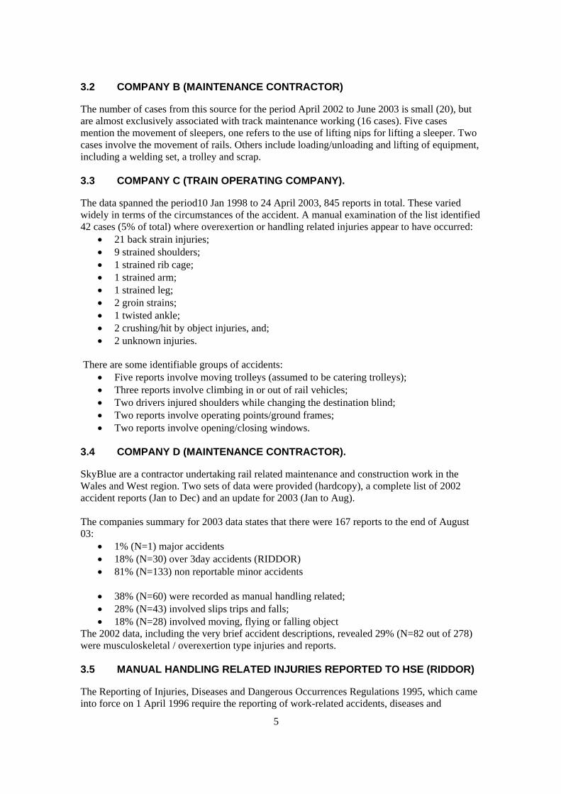
3.2 COMPANY B (MAINTENANCE CONTRACTOR)
The number of cases from this source for the period April 2002 to June 2003 is small (20), but
are almost exclusively associated with track maintenance working (16 cases). Five cases
mention the movement of sleepers, one refers to the use of lifting nips for lifting a sleeper. Two
cases involve the movement of rails. Others include loading/unloading and lifting of equipment,
including a welding set, a trolley and scrap.
3.3 COMPANY C (TRAIN OPERATING COMPANY).
The data spanned the period10 Jan 1998 to 24 April 2003, 845 reports in total. These varied
widely in terms of the circumstances of the accident. A manual examination of the list identified
42 cases (5% of total) where overexertion or handling related injuries appear to have occurred:
21 back strain injuries;
9 strained shoulders;
1 strained rib cage;
1 strained arm;
1 strained leg;
2 groin strains;
1 twisted ankle;
2 crushing/hit by object injuries, and;
2 unknown injuries.
There are some identifiable groups of accidents:
Five reports involve moving trolleys (assumed to be catering trolleys);
Three reports involve climbing in or out of rail vehicles;
Two drivers injured shoulders while changing the destination blind;
Two reports involve operating points/ground frames;
Two reports involve opening/closing windows.
3.4 COMPANY D (MAINTENANCE CONTRACTOR).
SkyBlue are a contractor undertaking rail related maintenance and construction work in the
Wales and West region. Two sets of data were provided (hardcopy), a complete list of 2002
accident reports (Jan to Dec) and an update for 2003 (Jan to Aug).
The companies summary for 2003 data states that there were 167 reports to the end of August
03:
1% (N=1) major accidents
18% (N=30) over 3day accidents (RIDDOR)
81% (N=133) non reportable minor accidents
38% (N=60) were recorded as manual handling related;
28% (N=43) involved slips trips and falls;
18% (N=28) involved moving, flying or falling object
The 2002 data, including the very brief accident descriptions, revealed 29% (N=82 out of 278)
were musculoskeletal / overexertion type injuries and reports.
3.5 MANUAL HANDLING RELATED INJURIES REPORTED TO HSE (RIDDOR)
The Reporting of Injuries, Diseases and Dangerous Occurrences Regulations 1995, which came
into force on 1 April 1996 require the reporting of work-related accidents, diseases and

6
dangerous occurrences. It applies to all work activities, but not to all incidents. In terms of
manual handling related injuries, the categories of interest are: accidents resulting in more than
3 days away from work, or unable to do the full range of their normal duties for more than three
days), and diseases (of which musculoskeletal disorders are included).
Over the period April 02 to March 03 there were 453 reports recorded as handling activity
(Table 1). We were provided with the full details of these cases, split between rail handling
operations and all other handling activities. A summary table of the injury nature and body part
involved is provided in Table 2 below for non-rail handling activities.
Table 1. HSE RIDDOR reported summary statistics (April 2002 - March 2003) for the rail sector
Fatal Serious Minor Total
Injured while
handling, lifting
or carrying other
than rail
1 44 362 407 (19%)
Injured while
handling rails by
manual or
mechanical means
0 13 33 46 (2%)
Total 1 57 395 453 (22%)
Total of all staff
non-movement
accidents
4 323 1713 2040
NB: The fatal accident occurred when unloading sleepers using a lifting device and sling, the
sling failed and the sleepers fell onto the deceased – this is not a manual handling accident.
Handling related injuries in the rail sector therefore constitute around 22% of the total injuries
reported to HSE for the sector.
Strain injuries are clearly the main injury type, accounting for nearly 58% of the total (see the
chart below). The three most frequent injuries are: strain of the back; laceration of the fingers,
and; fracture of the fingers. Fracture is the second most common injury type, perhaps a further
indication of the heavy nature of the manual handling in the rail sector.
Of the strain injuries, two thirds are to the back. The next most frequently injured body part is
the lower limb, at 6.4%, most of these injuries being strains.

7
Table 2. Manual handling records (not rail handling)
Nature of injury
Site of
Injury
Amputation Burn Concussion Contusion Dislocation Fracture Laceration Multiple Not
known
Strain Superficial Total
Unknown
(13)
6 5 5 2 1 2 1 22
Ankle 1 3 7 11
Back 4 1 2 155 1 163
Eye 1 1 2
Face 2 1 2 1 1 7
Finger 8 3 1 16 19 7 1 9 1 65
Foot 1 5 7 1 14
Hand 1 1
Head 1 2 1 4
Lower
Limb
7 1 3 3 1 1 15 31
Neck 1 6 7
Several
locations
1 10 2 6 19
Toe 1 2 1 4
Torso 3 3
Trunk 1 1 1 11 14
Upper
Limb
5 6 2 2 2 13 30
Wrist 3 1 2 4 10
(blank)
Total 8 1 1 35 2 48 36 25 12 235 4 407
Strain
58%
Not known
3%Multiple
6%
Laceration
9%
Fracture
12%
Burn
0%
Concussion
0%
Contusion
9%
Dislocation
0%
Amputation
2%Superficial
1%
Figure 2. RIDDOR 02/03 Handling (other than rails): Chart of nature of injury categories within handling records (percentages)
8
0.0
10.0
20.0
30.0
40.0
50.0
60.0
70.0
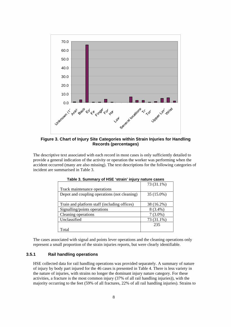
Figure 3. Chart of Injury Site Categories within Strain Injuries for Handling Records (percentages)
The descriptive text associated with each record in most cases is only sufficiently detailed to
provide a general indication of the activity or operation the worker was performing when the
accident occurred (many are also missing). The text descriptions for the following categories of
incident are summarised in Table 3.
Table 3. Summary of HSE ‘strain’ injury nature cases
Track maintenance operations
73 (31.1%)
Depot and coupling operations (not cleaning) 35 (15.0%)
Train and platform staff (including offices) 38 (16.2%)
Signalling/points operations 8 (3.4%)
Cleaning operations 7 (3.0%)
Unclassified 73 (31.1%)
Total
235
The cases associated with signal and points lever operations and the cleaning operations only
represent a small proportion of the strain injuries reports, but were clearly identifiable.
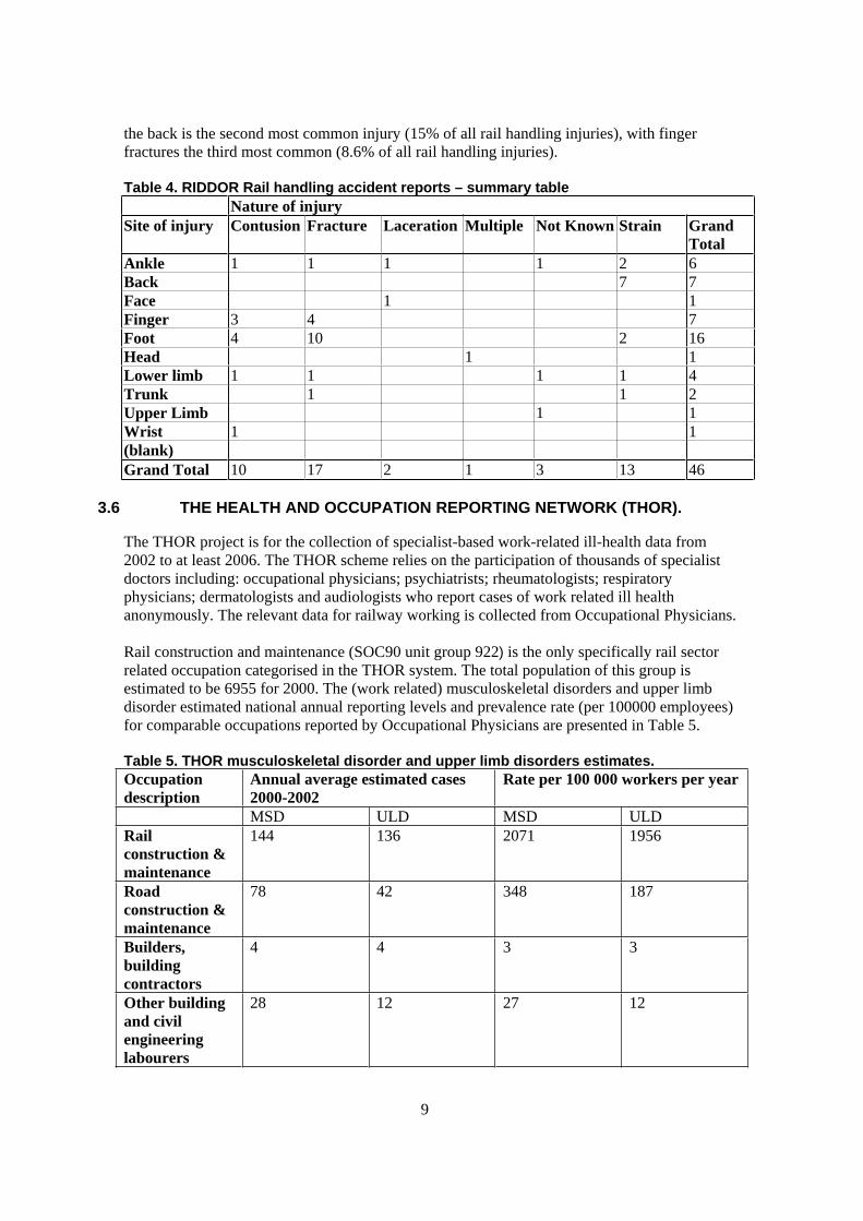
3.5.1 Rail handling operations
HSE collected data for rail handling operations was provided separately. A summary of nature
of injury by body part injured for the 46 cases is presented in Table 4. There is less variety in
the nature of injuries, with strains no longer the dominant injury nature category. For these
activities, a fracture is the most common injury (37% of all rail handling injuries)), with the
majority occurring to the feet (59% of all fractures, 22% of all rail handling injuries). Strains to
9
the back is the second most common injury (15% of all rail handling injuries), with finger
fractures the third most common (8.6% of all rail handling injuries).
Table 4. RIDDOR Rail handling accident reports – summary table
Nature of injury
Site of injury Contusion Fracture Laceration Multiple Not Known Strain Grand
Total
Ankle 1 1 1 1 2 6
Back 7 7
Face 1 1
Finger 3 4 7
Foot 4 10 2 16
Head 1 1
Lower limb 1 1 1 1 4
Trunk 1 1 2
Upper Limb 1 1
Wrist 1 1
(blank)
Grand Total 10 17 2 1 3 13 46
3.6 THE HEALTH AND OCCUPATION REPORTING NETWORK (THOR).
The THOR project is for the collection of specialist-based work-related ill-health data from
2002 to at least 2006. The THOR scheme relies on the participation of thousands of specialist
doctors including: occupational physicians; psychiatrists; rheumatologists; respiratory
physicians; dermatologists and audiologists who report cases of work related ill health
anonymously. The relevant data for railway working is collected from Occupational Physicians.
Rail construction and maintenance (SOC90 unit group 922) is the only specifically rail sector
related occupation categorised in the THOR system. The total population of this group is
estimated to be 6955 for 2000. The (work related) musculoskeletal disorders and upper limb
disorder estimated national annual reporting levels and prevalence rate (per 100000 employees)
for comparable occupations reported by Occupational Physicians are presented in Table 5.
Table 5. THOR musculoskeletal disorder and upper limb disorders estimates.
Occupation
description
Annual average estimated cases
2000-2002
Rate per 100 000 workers per year
MSD ULD MSD ULD
Rail
construction &
maintenance
144 136 2071 1956
Road
construction &
maintenance
78 42 348 187
Builders,
building
contractors
4 4 3 3
Other building
and civil
engineering
labourers
28 12 27 12
10
The railway construction and maintenance workers have the highest rate per 100000 workers of
all occupations included in the scheme for both MSD and ULD. The average rates per 100 000
workers for all occupations is 20 for MSD and 12 for ULD. However, drawing comparisons is
problematic due to the variation between companies and industry sectors in terms of
accessibility to occupational health provision. Availability within the rail sector is considered to
probably be better than for many other occupations as the rail industry companies we have had
contact with during this project typically have some in-house Occupational Health provision or
a referral procedure. However, even taking such variations into account, the level of reporting
for the rail sector is very high, suggesting that the work activities these workers perform present
a high level of risk for musculoskeletal injury
3.7 ACCIDENT AND REPORTING SUMMARY
There is limited data, however, handling operations are associated with around 22% of all
injuries reported to HSE. The THOR data indicates that rail maintenance and construction work
is associated with the highest rates of self reported ill health compared with other occupations.
Overall, although the various sources of information reflect the scope of different companies
and their operations, they indicate that the three groups most associated with a handling
accident/injury are:
Trackside maintenance workers;
Workers performing coupling/uncoupling of rolling stock and rolling stock maintenance,
and;
Train and platform staff more generally.
The proportion of musculoskeletal and handling related injuries for the train operating
companies and maintenance companies is not clear since we do not have overall figures,
however the proportion appears to be relatively low. In particular the number of relevant cases
amongst the Company C data was very low at around 5%. It is notable that, for the heavy
handling associated with the track and depot working, the manual handling injuries are not
confined to back strains. Although this is the most commonly occurring injury type, there are a
high proportion of fractures and crushing/trapping injuries to the hands and feet.
Point lever and signal lever operation are clearly identifiable in the data, and they are associated
with around 8% (RIDDOR) of non-rail handling injuries. Cleaning operations were also
identifiable with a small proportion of cases (7% - RIDDOR).
Under reporting of occupational ill health is known to occur, but the scale of it is unknown.
Besides a simple failure to report, there is an additional possibility that workers may not
perceive a link between their work activity and their musculoskeletal injury symptoms. The
above data does not take account of under reporting, and therefore may not present the true
scale of the problem.
For a further consideration of the level of prevalence of MSD injury in the rail sector, and a
comparison with other industry sectors, please see Section 5.
3.8 RECOMMENDATIONS
It would be useful in interpreting all sources of ill-health reports to establish the scale of
under-reporting.
Reduce the number of reports which are unclassified in the HSE collected RIDDOR data.

11
The active audit and monitoring of workforce musculoskeletal health is recommended. A
tool such as the HSE musculoskeletal symptoms questionnaire would be appropriate.
12
4 LITERATURE REVIEW
This focused on the literature specifically concerning rail industry work and evidence of
musculoskeletal injury and ill health. The risk factors for MSD have been established by major
reviews such as NIOSH (1997), and are also described in HSE publications on manual handling
operations and upper limb disorders (e.g. L23 and HSG60(rev)). The main physical risk factors
can be summarised as follows:
Repetition
Force / Lifting / forceful movement / Heavy physical work
Posture / Awkward posture / Static work posture
Vibration Whole body / hand-arm
Duration
There are also other factors to be considered, such as individual differences, environmental
factors and psychosocial factors. These are interrelated and interact to varying degrees
depending upon the situation.
A search was made of the ergonomics literature for rail industry related references concerning
musculoskeletal injury and ill-health. The aim of this exercise was to identifying rail industry
tasks, activities or operations which were associated with a high prevalence of musculoskeletal
injury and ill health. The Ergonomics Abstracts database was searched using various criteria in
an attempt to identify relevant information. The following papers were identified and reviewed,
and are presented under three headings, evidence of musculoskeletal ill-health in railway
workers, task and tool design issues and, training course design.
4.1 EVIDENCE OF MUSCULOSKELETAL ILL HEALTH IN RAILWAY WORKERS
Brulin et al (1985) Musculoskeletal problems in railway station personnel – a descriptive
epidemiological study.
This study was carried out by the Work Physiology Unit of the Swedish National Board of
Occupational Safety and Health. It includes 660 male ‘railway station’ participants which were
comprised of 509 shunters, 146 maintenance workers and 5 metal ore marshalling yard workers.
The age distribution was even from 20 to 60 years, and the time in job was mostly over 2 years.
The study employed the Nordic Musculoskeletal Questionnaire (NMQ) to examine the annual
and point prevalence of ‘trouble’ in body regions, and the extent of incapacity associated with
cases. The incidence of musculoskeletal problems (over the previous 12 months) was greatest in
the knees 40%, lumbar region 38% and ankles/feet 26%.
Of those reporting problems with the last 12 months, between 28 and 43% reported inability to
carry out work or leisure activity as a result. Again 29 to 43% of those reporting problems, also
reported occurrence of that problem during the previous 7 days. Lumbar problems were
associated most with incapacity. The percentage of problems tended to increase with worker age
and period of employment. This data is compared with NMQ responses from Track workers
collected as part of this study, and other reference sources, in Section 6.
Virokannas et al (1994) Health risk assessment of noise, hand-arm vibration and cold in
railway track maintenance.
This study included a health survey of 252 Finnish track maintenance workers, out of an
estimated population of around 600. the majority of the exposure to hand-arm vibration risk was

13
reported to be associated with the use of hand-held tampers. Interestingly, no other powered
machinery is identified. Over 30% of the subjects had suffered with symptoms of vibration
induced ill-health including numbness, tingling and disturbed sleep. Cold was another risk
factor for ULD, but the temperatures associated with work in Finland are considerably lower
than would be expected in the UK (+2 to –28 C mean daily ambient temperature range).
Peerreboom (1993) A strategy for using the Ovako working posture analysing system
(OWAS) to determine the physical load of actions.
This paper is more concerned with the usefulness of the OWAS approach rather than the work
of rail workers, but there are some interesting statistics. The author reports that in the
Netherlands, the rail industry experienced an absenteeism rate of 7.9% (1991 figure), and of
these cases, 24% were associated with musculoskeletal ill health, comprising the largest single
category. Looking specifically at railway maintenance staff and mechanics, the proportion rose
to over 30%.
The OWAS analysis of railway maintenance operations for 10 activity categories revealed that
handling tools, using mechanically driven tools, and manually lifting parts were the 3 most high
risk operations.
4.2 TASK AND TOOL DESIGN ISSUES
Morgan, M. (2002) Visit to Company B Yard and Maintenance Facility, 19.06.02.
This is an HSE Inspection Report describing a site visit to discuss manual handling in rail
maintenance activity and the tools used. The tools included are as follows:
1. Iron man rail lifter and carrier – an A-frame based lifting device
2. Rail Scooter – a lever based manual lifting aid
3. Sleeper nips (wooden)
4. Sleeper callipers (concrete)
5. Rail trolley – two part trolley
6. Rail skate – single rail running device for moving batteries etc.
7. Pan-puller
8. Duff Norton Rail Jack
9. Generator and Stone blower – for moving ballast
10. Rail fastenings – rail chairs, chair screws, clips, etc..
The implications for getting these items onto the work site are highlighted. Many of the tools
are by necessity of heavy construction, and some do break down into more manageable parts for
carrying. However, many of these a still of a significant weight for an awkward lift or a long
carry. Potential improvements to the design of the many of the tools are also suggested.
Nath Sen and Sahu (1996) Ergonomic evaluation of a multipurpose shovel-cum-hoe for
manual material handling.
The authors propose a new design of shovel/hoe tool which can be used in materials handling
and movement operations such as railway maintenance. The tool can be used as a conventional
shovel, but switched to a hoe for dragging material – something which is frequently done with
ballast, for example when building up the shoulder, and when digging out the space for a
replacement sleeper. The authors claim that the tool was accepted by experienced workers, and
served both purposes without additional physiological penalty, based upon Heart Rate and
Ratings of Perceived Exertion.
Page et al (1990) The development of ergonomic guidelines for railroad hand switch
operation.
According to the US Federal Railroad Administration (1989), around 14000 lost time accidents
occur each year in the rail industry. Workers who work in yards incur 16% of the injures while

14
they work 8% of the man hours. A previous study by Kuciemba, Page and Kerk (1988)
identified that the operation of hand switch stands/switches is an operation contributing to a
high proportion of the injuries, 43% of which are to the low back.
The hand switch of concern here is equivalent to the ground frame or points lever found in the
UK in terms of function, however, the nature of the switch and its operation appears to be quite
different (Figure 4).
The posture adopted is very different from that required for similar functions in the UK, and is
considered to present a higher risk of injury due to the need to apply force with one hand, at
near ground level, and across the body
Figure 4. Example of hand switch operation at the beginning
of lever motion. From Page et al 1990.
The researchers used video analysis of 20 workers performing 50 operations to establish
postures throughout the lever movement range and the University of Michigan3D SSPP
biomechanical model (in reverse ) to establish a guideline hand force figure. This was done
iteratively to produce a maximum hand force figure for the back compression ‘Design Limit’
and ‘Upper Limit’ in each posture (Figure 5).
While this study does not provide any indication of actual hand forces applied, the resulting
guidelines suggest that initial forces as high as around 60kgf, and ongoing forces of around
90kgf through the lever arc would not exceed the back compression ‘Design Limit’ for the
operating postures observed. [NB: These forces are comparable with those measured later in this
study for lever operation, but the posture is quite different].
These are large forces when compared with human capability data. The starting force alone of
around 60kgf is very significant, especially considering the posture. The finishing force of up to
180kgf is extreme, even considering that this could include a significant contribution from
bodyweight. However, in terms of relevance to the current study, the paper appears to suggest
two things: forces as high as these might be fairly common in rail switch operation, and; these
forces would be a cause of some concern.

15
Figure 5. Ergonomics guidelines for switch stand evaluation. From Page et al 1990.
Sen (1988) Ergonomics design of some tools for manual maintenance of railway tracks in
India.
Unfortunately in this paper there are no pictures of the tools that are being discussed. New
designs of a ‘Beater’ (unknown function) and ballast rake are described, which have been
developed through trial with Permanent Way gang men, using physiological and subjective
data.
The Beater:
Was modified to minimise the fatiguing posture observed.
The beater head was modified for packing of ballast – with a slightly curved head.
Antivibration measures included mounting rubber between head and handle, and the use of
perforated rubber sleeving on grip areas of the handle.
The Ballast Rake:
It appears that the rake is probably used by three workers together. One places the head, and the
others pull the rake using a chain or rope.
The rake was modified to have a handle that did not require the placer to bend forward as much.
The number of rake prongs was increased.
The chains were made detachable.
The prongs were made shorter so that they did not penetrate as far into the ballast.
The weight of the rake and chains was around 4kg.
Mannchen (1972) Ergonomic considerations for the development and use of an automatic
central buffer coupling in the shunting operations of the German Reich Railways.
This study looks at the energy expenditure requirements of the traditional versus automated
coupling technology emerging at the time. The coupling sequence is described which is similar
to that seen in the UK. The worker has to enter the area between the buffers of the wagons to
make and break coupling connections. The use of pole is mentioned in the uncoupling of units,
used as a lever across the ‘hump’ of the buffer from outside of the tracks. The main conclusions
concern the reduction in energy expenditure associated with the auto-coupling, arising from the
reduced walking distances, eliminating the need to go under and between the buffers, and
reduced physical load.

16
Amell T.K, Kumar S. (2001) Industrial handwheel actuation and the human operator: a
review.
One paper identified in the literature search as relevant to rail industry working concerns
handwheel operation. A review of sources of guidance on handwheel operation, and collation
into a set of recommendations for force limits and handwheel design characteristics. These are
relevant for the design of a wheel actuated handbrakes on wagons. Handwheels are known to be
used for the application of brakes on goods wagons in the UK, but these were not seen during
the current study.
EWS (2001) Guide to Manual Handling for Shunting Tasks
This publication is aimed at the EWS workforce. As well as providing background to the
anatomy of the spine and good and poor posture, the publication provides a series of twelve
examples illustrating the advised approach to reduce the risks of back injury.
These include:
Picking up objects from the ground
Working with and under buffers
Working with couplings
Operating points levers
Using a brake stick
Operating a handbrake wheel
This publication is seen as useful basis for a training course for shunting yard work, and a
reinforcement of the training message. How effective it is in terms of achieving readership
outside the training course is questionable, but as a reference source it is valuable. It is
considered to be in need of some updating in terms of the technical content in some areas. While
the rationale for the choice of example tasks is not known, it seems reasonable to assume that
those featured can be considered to be associated with high injury rates.
Regional Railways (undated) Manual Handling and Lifting - Civil Engineering.
This is a similar publication to that of EWS, it provides background material on the Health and
Safety Legislation and employers and employees duties, the spine, kinematics and
musculoskeletal ill health more generally. It explains the risk factors associated with manual
handling. Example tasks are used to illustrate good and poor practice, these include:
Pushing and pulling including barring,
Shovelling
Hammering
Lifting
Team handling of rail and sleepers
It is difficult to convey subtle differences in posture in two photographs for each task example,
but some of the examples are somewhat staged and present the ‘wrong’ way of doing things
rather in the extreme. Others are more credible, but for the sake of credibility it may be better
simply to illustrate good practice. Generally the advice is sound and pragmatic, and could
usefully be updated in the light of recent HSE research on principles of safe manual handling
(Graveling et al 2003).
The example of concrete sleeper lifting (F40 – 284kg) shows a type of lifting aid not seen
elsewhere. This is a very large T-bar arrangement, allowing 4 men to use it, two either side of
the sleeper. One of these tools is used at both ends of the sleeper to enable 8 men to make the
lift. The size of the rise on the T-bar handle is such that the men in the illustration are grasping
the handle at around elbow height. This is not known to be the optimal position for applying

17
upward lifting force. A level around knuckle height would be more suitable (some form of
adjustment would be desirable and practical on devices of this size).
As in the EWS publication, the inclusion of these examples in a publication can be considered
as evidence that they are associated with overexertion injuries and musculoskeletal ill health.
4.3 TRAINING DESIGN
Gagnon (2003) The efficacy of training for three manual handling strategies based on the
observation of expert and novice workers.
This paper looks in some depth at the effects of a particular training approach where novices are
trained in safe handling methods using observation of novice and expert handlers as well as
explanation. From the results of an experimental investigation the author concludes that a
training program based upon contrasting the approaches of expert and novice workers is
successful at reducing injury risk by encouraging better handling technique. The recommended
focus is on load manoeuvring, load tilting, hand positioning and feet placement.
Section 8 contains a critique of the manual handling training provided to track maintenance
workers.
4.4 SUMMARY
By comparison with other industry sectors that have heavy manual handling operations, such as
construction, the manual handling research focusing on the rail sector has been limited. We
were successful in obtaining a small number of sources of scientific literature that are of
assistance in the identification of operations presenting a high risk of musculoskeletal injury or
ill health directly relevant to the rail sector. Those sources that were found suggest that the
following activities have been considered to present a high risk of musculoskeletal injury or ill
health by other researchers and organisations:
Railway track maintenance work, heavy lifting operations (e.g. sleepers), pushing and
pulling loads, barring and levering, and work involving the use of vibrating tools and
exposure to cold
Ballast shovelling and raking work
Rail vehicle maintenance
Shunting yard work, including points levers (manual switch) and coupling operations.
18
5 HSE MUSCULOSKELETAL SYMPTOMS QUESTIONNAIRE
A shortened version of the HSE Nordic Musculoskeletal Symptoms Questionnaire (HSENMQ)
was administered where practical during the site visits in order to try to gain an indication of the
proportion of workers who are experiencing musculoskeletal problems at and outside work.
This included the prevalence section of the questionnaire (shown in Appendix 2). The
questionnaire has been applied quite widely in a number of industry sectors over the years and it
was considered informative to compare the rate of MSD reporting among track maintenance
workers with that of other professions. The questionnaire was administered by the researchers
during the site visits, on a one-to-one basis. All responses are from Carillion employees. The
study was explained briefly before the HSEMSSQ questions were asked. A body map was
provided to help define the body areas dealt with in the questions. Twenty five workers
responded.
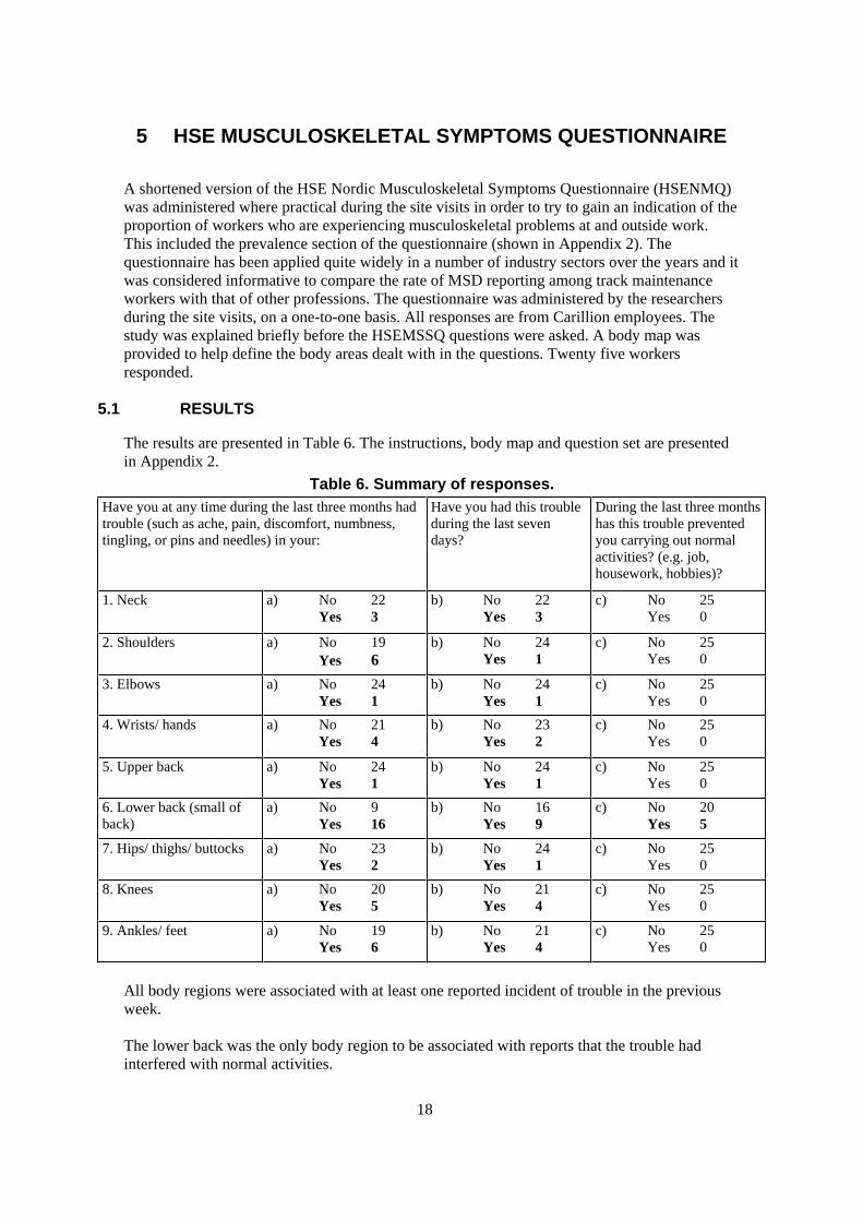
5.1 RESULTS
The results are presented in Table 6. The instructions, body map and question set are presented
in Appendix 2.
Table 6. Summary of responses.
Have you at any time during the last three months had
trouble (such as ache, pain, discomfort, numbness,
tingling, or pins and needles) in your:
Have you had this trouble
during the last seven
days?
During the last three months
has this trouble prevented
you carrying out normal
activities? (e.g. job,
housework, hobbies)?
1. Neck a) No 22
Yes 3
b) No 22
Yes 3
c) No 25
Yes 0
2. Shoulders a) No 19
Yes 6
b) No 24
Yes 1
c) No 25
Yes 0
3. Elbows a) No 24
Yes 1
b) No 24
Yes 1
c) No 25
Yes 0
4. Wrists/ hands a) No 21
Yes 4
b) No 23
Yes 2
c) No 25
Yes 0
5. Upper back a) No 24
Yes 1
b) No 24
Yes 1
c) No 25
Yes 0
6. Lower back (small of
back)
a) No 9
Yes 16
b) No 16
Yes 9
c) No 20
Yes 5
7. Hips/ thighs/ buttocks a) No 23
Yes 2
b) No 24
Yes 1
c) No 25
Yes 0
8. Knees a) No 20
Yes 5
b) No 21
Yes 4
c) No 25
Yes 0
9. Ankles/ feet a) No 19
Yes 6
b) No 21
Yes 4
c) No 25
Yes 0
All body regions were associated with at least one reported incident of trouble in the previous
week.
The lower back was the only body region to be associated with reports that the trouble had
interfered with normal activities.

19
The most significant finding concerns the reporting of trouble in the region of the lower back.
Over half of respondents have experienced musculoskeletal trouble in the lower back in the last
three months. 36% had experienced this within the previous week, and 20% reported that this
was serious enough to prevent them from carrying out normal activities at and outside work.
The next most frequently reported troubles were:
Shoulders (24%);
Ankles and feet (24%);
Knees (20%);
Wrists and hands (16%), and;
Neck (12%).
5.1.1 Comparison with other sources of musculoskeletal symptom data for other industry sectors
5.1.1.1 Rail sector workers
A directly relevant comparable data set is that presented by Brulin et al (1995). This is a NMQ
based survey of musculoskeletal symptoms reporting in rail sector workers made up from
shunting yard workers and rolling stock maintenance personnel. (n=660).
Figure 6. Comparison of Track worker annual prevalence with railway worker data from Brulin et al (1995)
0.0
10.0
20.0
30.0
40.0
50.0
60.0
70.0
Railway Workers(Brulin et al 1995,n=660)
Track workerresponses (n=25)
From our study, the activities of the shunters and maintenance personnel are likely to quite
different in terms of the amount of hard physical work and heavy lifting performed from the
track maintenance worker. This is probably the reason for the marked difference in reporting of
Low Back problems.

20
5.1.1.2 Other industry sectors
Since the HSEMSSQ is adapted from the NMQ, which has been applied widely, there is a
reasonable body of directly comparable data. Annual and some weekly prevalence data are
available for comparison.
The Nordic reference data gathered using the NMQ is a large sample of over 7569 workers
(Foundation for Occupational and Environmental medical research and Development, Orebro,
1985/86/87), and represents average occupational prevalence of MSD. Within the Nordic
sample are data for comparable outdoor heavy manual jobs such as Lumberjacks, Engineering
Mechanics and Construction workers. These are presented for comparison in Figure 7.
Figure 7. Comparison of Trackworker annual prevalence with Nordic reference data (1986/7)
0.0
10.0
20.0
30.0
40.0
50.0
60.0
70.0
Lumberjack (n=40)
Engineering Mechanic(n=56)
Construction Worker(n=104)
Nordic - all industry(n=7569)
Track workerresponses (n=25)
The HSE reference data (Dickinson 1994) is based on a range of HSE studies using the NMQ
(1998 male workers in 9 different work settings), The HSEMSSQ uses a three month prevalence
to indicate annual prevalence. The all industry HSE reference data is shown below in Figure 8.
The comparative data sources used here are summarised in Appendix 3.

21
Figure 8. Comparison of Trackworker annual prevalence with HSE cross industry reference data for males (1994)
0.0
10.0
20.0
30.0
40.0
50.0
60.0
70.0
Track workerresponses
HSEreferencedata mean
HSEreferencedata median
Further HSE reference data has been collected in a separate survey of construction workers
(1999). This data is presented in Figure 9 below.
Figure 9. Comparison or Track worker annual prevalence with HSE reference data for construction workers (1999)
0
10
20
30
40
50
60
70Ground workers(n=41)
General Labourers(n=88)
Track workerresponses (n=25)

22
Comparative data for the weekly prevalence results is only available for the Nordic all industry
reference data (Table 7).
Table 7. Weekly prevalence comparative data
Track
maintenance
workers
Nordic reference
data: all industry
(1985)1. Neck 12% 11% 2. Shoulders 4% 11% 3. Elbows 4% 4% 4. Wrists/ hands 8% 6% 5. Upper back 4% 4% 6. Lower back
(small of back) 36% 15%
7. Hips/ thighs/
buttocks 4% 5%
8. Knees 16% 10% 9. Ankles/ feet 16% 6%
5.1.1.3 Disability prevalence
The three monthly disability prevalence for the track maintenance workers is 20% for Lower
Back Trouble. This figure can be compared with a Lower Back annual disability figures of 13%
in the Nordic all industry reference data, and 15% for the Brick packers. There was zero
disability reported for the other body areas amongst the track maintenance workers.
5.2 CONCLUSIONS
Given the small sample size it is unadvisable to try to statistically place too much weight on
the comparisons, but indications are that the track maintenance worker groups that we
interviewed report a higher prevalence of lower back and ankle/feet problems than any of
the other reference populations, for both the long term and weekly time periods. This is
what might be reasonable to expect given the nature of the track maintenance tasks and
environment.
The level of prevalence for disability in the lower back was higher among the track
maintenance workers than the reference population data available.
For other body areas the level of annual prevalence in the track maintenance workers is
comparable or lower than the reference populations.
The HSEMSSQ is more sensitive than accident reports/records in gaining information about
the prevalence of musculoskeletal symptoms amongst the workforce. The questionnaire
appeared to be easily understood by all workers interviewed, both in terms of the questions
and the body parts included. It was very quick and easy to apply, although there is some
doubt as to whether it could be employed effectively as a self-completion tool in the current
setting.
23
5.3 RECOMMENDATIONS
Based upon our application of the HSEMSSQ the following recommendations for this purpose
can be made:
The HSEMSSQ in an abbreviated or full form is considered to be of potential benefit as an
active musculoskeletal health monitoring tool;
It should be applied anonymously;
It should be applied by an interviewer rather than by self completion;
For active monitoring purposes it should be administered every 1 to 2 years;
A section for identifying contributory work activities would be a useful addition.
Consider including the section for identifying psychosocial factors.

24
6 SITE VISITS DETAILS
Based upon the finding of the accident and ill health reporting, the literature review and our
experiences from the site visits made thus far, the Project Team agreed that the rest of the study
should concentrate on the following activities:
Track work, concentrating on sleeper and rail handling, plus tools and equipment used;
Depot operations, specifically coupling, point lever and ground frame operation.
Making the necessary arrangements for us to have access trackside at the right time and place to
be able to see those activities we had identified was not straightforward, but the RI/SG team
arranged a series of successful visits. The work sites were geographically spread across the
South Wales region, often in remote locations.
Further details for the Phase 2 activities are provided separately in Section 7.
25
7 OPERATIONS AND EQUIPMENT FOR DETAILED CONSIDERATION
During a project team meeting, and following initial site visits, the project team agreed that the
manual handling operations for detailed consideration should be confined to the following:
Shunting yard coupling operation
Points and Signal Box semaphore lever operation tasks
Sleeper changing - Wooden
Concrete
Loading and unloading of tools and equipment at site
Use of selected tools Rail profile grinder
Petrol Nut-runner
Rail disc cutter
Sleeper and rail lifting tongs
Rail jacks
Rail trolleys
Kangura ballast bucket
Generators
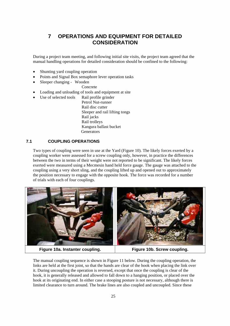
7.1 COUPLING OPERATIONS
Two types of coupling were seen in use at the Yard (Figure 10). The likely forces exerted by a
coupling worker were assessed for a screw coupling only, however, in practice the differences
between the two in terms of their weight were not reported to be significant. The likely forces
exerted were measured using a Mecmesin hand held force gauge. The gauge was attached to the
coupling using a very short sling, and the coupling lifted up and opened out to approximately
the position necessary to engage with the opposite hook. The force was recorded for a number
of trials with each of four couplings.
Figure 10a. Instanter coupling. Figure 10b. Screw coupling.
The manual coupling sequence is shown in Figure 11 below. During the coupling operation, the
links are held at the first joint, so that the hands are clear of the hook when placing the link over
it. During uncoupling the operation is reversed, except that once the coupling is clear of the
hook, it is generally released and allowed to fall down to a hanging position, or placed over the
hook at its originating end. In either case a stooping posture is not necessary, although there is
limited clearance to turn around. The brake lines are also coupled and uncoupled. Since these
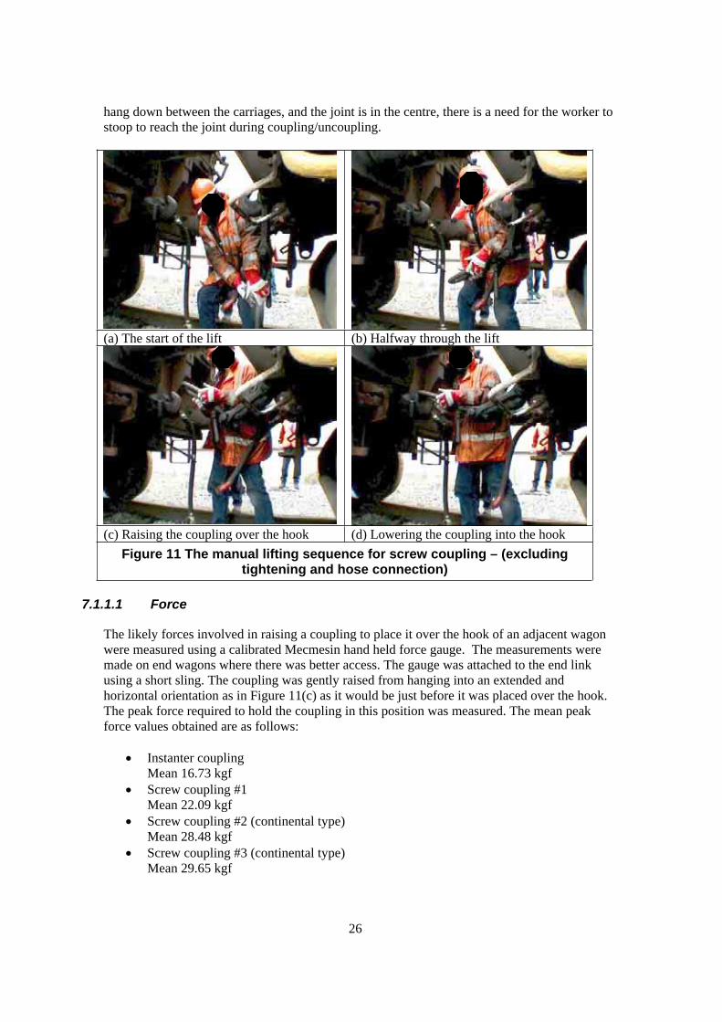
26
hang down between the carriages, and the joint is in the centre, there is a need for the worker to
stoop to reach the joint during coupling/uncoupling.
(a) The start of the lift (b) Halfway through the lift
(c) Raising the coupling over the hook (d) Lowering the coupling into the hook
Figure 11 The manual lifting sequence for screw coupling – (excluding tightening and hose connection)
7.1.1.1 Force
The likely forces involved in raising a coupling to place it over the hook of an adjacent wagon
were measured using a calibrated Mecmesin hand held force gauge. The measurements were
made on end wagons where there was better access. The gauge was attached to the end link
using a short sling. The coupling was gently raised from hanging into an extended and
horizontal orientation as in Figure 11(c) as it would be just before it was placed over the hook.
The peak force required to hold the coupling in this position was measured. The mean peak
force values obtained are as follows:
Instanter coupling
Mean 16.73 kgf
Screw coupling #1
Mean 22.09 kgf
Screw coupling #2 (continental type)
Mean 28.48 kgf
Screw coupling #3 (continental type)
Mean 29.65 kgf
27
7.1.1.2 Posture
As can be seen in Figure 11(a). the lift initiates with a moderate stoop to grasp the coupling with
both hands. It is not a symmetrical lift. The hands are raised and moved across in front of the
body to some extent, but towards the end of the lift the coupling is held just to one side of the
midline of the body. There is also a small amount of trunk twist, evident by the rotation of the
shoulders, estimated to be less than 45 degrees. The operation ends with the worker stood
upright with the upper body slightly rotated.
The worker has to access to the coupling with means that they will adopt around 90 degree
forward trunk flexion or a semi-squat posture when moving in and out under the buffers for
each coupling connected or disconnected.
7.1.1.3 Frequency/Duration
The workers reported variations in the workload for coupling and uncoupling. In the shunting
yard the workload for coupling is steady, and consistent, with a certain number of breaks or
connections to be made for each set of rolling stock arriving and leaving. A typical day was
reported to require 2 or 3 couplings per train to be broken/made, on about 20 trains per shift.
It was reported that on some sections of line the curves were tighter than standard, and that this
necessitated every screw coupling to be loosened when taking rolling stock in, and every
coupling tightened when coming out. This was reported to be done on approximately 30 trains
per day, and up to 20-24 wagons/train.
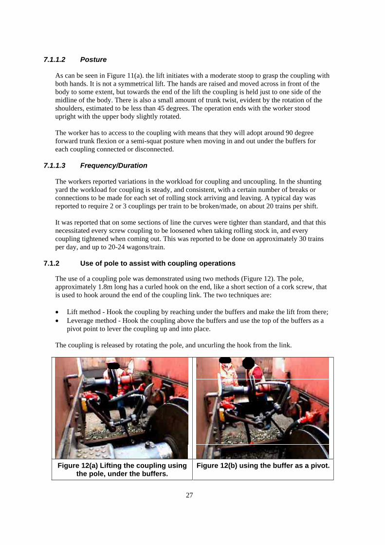
7.1.2 Use of pole to assist with coupling operations
The use of a coupling pole was demonstrated using two methods (Figure 12). The pole,
approximately 1.8m long has a curled hook on the end, like a short section of a cork screw, that
is used to hook around the end of the coupling link. The two techniques are:
Lift method - Hook the coupling by reaching under the buffers and make the lift from there;
Leverage method - Hook the coupling above the buffers and use the top of the buffers as a
pivot point to lever the coupling up and into place.
The coupling is released by rotating the pole, and uncurling the hook from the link.
Figure 12(a) Lifting the coupling using the pole, under the buffers.
Figure 12(b) using the buffer as a pivot.
28
It is not known to what extent the pole is routinely used in coupling operations. The yard
manager admitted that he was out of practice at doing this, and in fact preferred to get in
between the wagons and lift the coupling on with his hands. Allowing for this, from observation
both of the operations appeared to be very awkward indeed, and require a significant amount of
force to be exerted, even using the leverage method. The direct lift using the pole appeared to be
extremely difficult and require an excessive amount of force to be exerted. It is accepted that a
greater degree of skill and technique would probably reduce the load somewhat, if the coupling
is swung upwards with the pole and the momentum used to gain the height necessary, but to
achieve this level of control, while lifting the weight of the coupling at such a remote distance is
considered to present a very high risk of injury. Enabling workers to develop such a level of
skill without putting them at risk would seem to be very difficult to achieve.
The leverage method enables a downward force to be exerted on the pole end, using
bodyweight, control in this situation is easier, however the amount of downward force exerted
on the pole is significant and the pole can be seen bending in Figure 12(b).
7.1.2.1 Overall Assessment and Recommendations
Situations where coupling and/or uncoupling operations are performed intensively should be the
subject of special risk assessments, and appropriate control measures investigated. For example,
these might include rotation of staff to other duties at suitable intervals, or increasing staff
numbers.
Presented in increasing level of risk of MSD risk:
Hand lifting method
The load is smallest when the worker is in the poorest posture for lifting, and greatest when the
workers posture is upright. The lifting action is asymmetric, with some trunk twist. The
magnitude of the load can exceed the L23 risk filter figure by a small margin. The risk of a low
back injury or other musculoskeletal injury is considered to be moderate to high. A detailed risk
assessment is therefore warranted as there may be other factors such as high repetition,
differences in space available, body size of workers, underfoot conditions, etc, that can increase
the risk further.
If the lift can be performed more symmetrically and with less twist, the risk may be reduced
further. For example, if the worker were to start the lift with their back closer to the origin of the
coupling (provided there is enough space), and the coupling passing under one arm, the lift
could be made more symmetrical. This should be investigated more formally and if successful
included in training programmes.
Pole leverage method
Body weight can be used to exert a downward force on the pole. This force appears to be great,
and control was observed to be difficult. The pole was observed to bend excessively. Postural
risks are low, but repetitive localised pressure in applying such large forces to the pole has
potential to cause other problems. The risk of a low back injury is considered to be low while
the risk of other musculoskeletal injury is considered to be high. Based upon this observation,
the approach is not recommended as a risk control option in place of the hand lifting method
above.

29
Pole lift method
The force exerted in the final stage of applying this approach, the posture necessary, and the
degree of control required are considered to present a very high risk of injury. This method is
not recommended.
7.2 LEVER OPERATION TASKS
7.2.1 Point levers
Figure 13. Points lever operation - start of pull.
At a Shunting Yard the operating force at 8 points levers was measured using a calibrated
Mecmesin handheld force gauge.
7.2.1.1 Force measurement
The force gauge was attached to the lever handle using a very short sling pulled tight to grip the
handle at the approximate mid point of the lever handle. The handles of the force gauge were
used to apply the force to the lever. The force application was made by one of the researchers,
and/or a practiced operator. The force was applied in a controlled but dynamic manner, as close
to normal operation as possible. The use of the force gauge did alter the posture adopted
somewhat during the operating task, but the force measurement is considered to be highly
indicative of what would normally be required.
Because of the nature of the points movement mechanism, it is typical for points levers to have
different operating forces depending upon which direction the point is being moved. The forces
were measured for both directions.
The mean peak operating forces as follows:
50.3kgf for the easy direction
58.3kgf for the hardest direction
54.3kgf overall
The highest measured forces exceeded 100kgf where the mechanism jammed on some
occasions.
30
The lever length is typically 1200mm. Some levers were measured as 1150mm in length.
Additional points lever force measurements were made at a depot. For the point levers the mean
peak forces for each direction were 22.1kgf and 52.5kgf respectively.
The overall mean peak force for all points levers measured is then 42.9kgf.
A ground frame was operated (by the Shunter). The peak force measured as above (once only)
at 79.34 kgf.
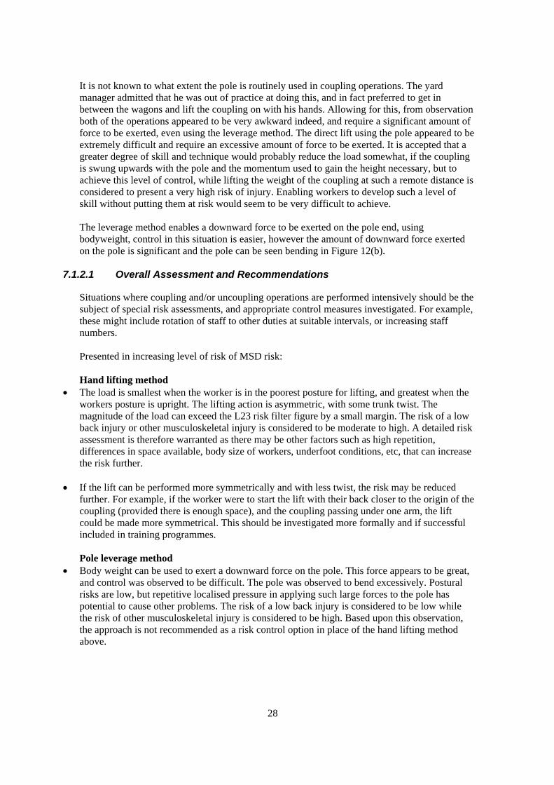
7.2.2 Signal box lever operation
The force required to actuate various signal levers was measured within a signal box. These
levers operate semaphore signals some distance from the Signal Box, and they are actuated by a
mechanical connection with the lever in the box. It was reported that the lever frame within the
box was of Great Western origin, while the signals themselves were of LMS origin. It was
suggested that this pairing contributed to the high levels of force required to actuate some of the
signals.
Since there were a large number of levers in the frame, those that were measured were confined
to those that the Signalman reported to require the most force to operate. The measurements
were made using a calibrated Mecmesin handheld force gauge. The gauge was attached to the
lever handle using a very short strop. Several measures were made for each. Some of the force
measurements were made with the Signalman applying the force, and some by one of the
researchers. The presence of the meter and the act of applying the force through it did influence
the posture adopted by the operator, but this is considered to have had minimal effect on the
force applied. The actual postures involved were gathered from video footage of the Signalman
undertaking the lever operation in the usual manner, see Figure 14 below.
(a) The start of the pull.

31
(b) Halfway through the pull as the force
requirement increases.
(c) The final posture at the end of the pull
where the force required is at its peak.
Figure 14. Posture of signalman during operation of a lever in the
signal box.
The levers were measured as 1190mm long from the pivot. Some of the levers were shorter at
1050mm. The length of the lever throw, or arc was measured as a movement of approximately
1250mm horizontally
Points Lever No. 32
Mean 49kgf
Points Lever No. 34
Mean 96.5
Points Lever No. 10.
Mean 78.0
Points lever No. 3
Mean 98.6
The overall mean peak operating force for all levers measured here is 80.5kgf. Peak forces of up
to 107kgf were obtained. Typically the maximum force is required at the end of the level throw.
The levers do not require high forces to return them to the resting position.

32
Table 8. Summary of operating force
Mean peak operating force
(kgf)
Absolute peak force
measured (kgf)
Points levers 42.9 103
Signal box levers 80.5 107
It is worth pointing out that the Points levers measured were included on the basis of
opportunity sampling, and are from two locations. The Signal box levers were identified to us as
being those requiring the greatest force to actuate, and come from a single signal box.
7.2.2.1 Posture
As can be see in Figures 13. and 14, the starting posture for both lever pull operations is similar.
The operating posture for the signal lever is extreme towards the end of the lever throw. This is
where the force required is greatest. The signalman used his body weight to achieve the level of
force required and consequently is allowing his centre of gravity to swing back over his rear
foot, and using the lever and his front foot for support.
During the early stages of the lever movement the force required is only moderate, but builds up
quickly into the mid stage, and the signalman’s posture shows some trunk flexion during this
phase, and he pulls with straight arms. During the final phase the trunk posture is less flexed,
and the arms begin to flex to pull the lever towards the body.
For the point levers, the posture recommended in the Company A Guide to Manual Handling
for Shunting Tasks (Figure 15), is representative of the starting posture for the force application,
but for those levers requiring high forces, the posture at the end of the pull was observed to be
approaching that adopted by the Signalman for the operation of signal box levers.
Figure 15. The posture recommended for operating points levers
in the Company A Guide to Manual Handling for Shunting Tasks.
In practice the height at which force is applied to the lever handle is somewhere between elbow
and shoulder height for most workers. The shoulder height of British males is between
33
approximately 1370-1580mm, and elbow height is between 1035-1200mm (5th to 95th centile
shod). Although the typical lever length is 1190mm the pivot is above ground level.
Strength data (Adultdata 1998) suggests that maximum horizontal pull forces appear to be
applied at a relatively low level, elbow height and below. It is believed that this level enables
most effective use of body weight. However, although the human body may be best able to
exert force at this level, this does not necessarily mean that the posture involved is optimal in
terms of minimising the risk of musculoskeletal injury. In this respect the present height of lever
is considered to be suitable.
7.2.2.2 Repetition
We do not have this information. This is likely to vary between signal boxes, but as these are
semaphore signals and points with mechanical connections, and these are now limited to low
traffic areas such as shunting yards, the requirement for operating them in a highly repetitive
manner seems unlikely. Certainly the pace of operating the levers in the signal box visited was
relaxed.
7.2.2.3 Duration
The duration of each lever pull ranged between 5.4 and 1.8 seconds for the full throw, however,
the high force is only applied for a proportion of this time. Normally only one or two levers
would be operated as part of any single point and signal setting operation, and it is very unlikely
that more than one of the ‘difficult’ levers would need to be operated.
7.2.3 Assessment
In terms of recommended pushing and pulling forces, the mean peak forces exceed all
recommended force guidelines by some margin. The push pull guidance in L23 suggests a
detailed risk assessment if initial pushing of pulling forces exceed 20kgf. The peak forces
measured here are 4 to 5 times as great.
The peak forces measured at the signal box exceed the maximum Acceptable Force of Pull
(MAFP)for males derived by Snook and Ciriello (1991). The MAFP derived was 69kgf for a
single pull for 2.1m (once every 8 hours) at 640mm above floor level. The Snook and Ciriello
data suggests that pulls at higher levels above the floor at 1440mm (closer to the point lever at
1200mm) produced lower maximal forces.
The British and European Standard BS EN 1005-3:2002 presents recommendations for force
limits based upon human capability data. The recommended maximum actuating force for
machinery relevant to the lever operation task is 145 N (14.8 kgf) (for a professional user, based
upon 15th percentile strength data). This maximum force value is then modified by the
application of multipliers for a the following risk factors:
Velocity
Frequency
Duration
In the case of the lever operation task, the velocity multiplier is considered to be relevant, as the
operation is typically dynamic. However, as even in the case of the signal box worker, the lever
operation is not performed with high frequency, the frequency and duration multipliers can be
ignored. The application of the velocity multiplier reduces the recommended maximum force
value to 11.6 N (11.8kgf)

34
7.2.3.1 Biomechanical modelling.
An assessment of the lever pulling task was made using the University of Michigan Static
Strength Prediction Program (SSPP). This software allows a biomechanical calculation of the
loads on various parts of the body to be made, given the posture and hand loads. Most
importantly, the model calculates the compression force acting on the worker’s lower back
(L5/S1 the joint between the lowest vertebra and the sacrum). Compression force is considered
to be a critical element of low back injury (Chaffin and Anderson, 1984) and the L5/S1 joint is
the point at which the greatest load exists and therefore the most likely site of injury (Waters et
al 1993).
The SSPP model can only estimate loads from a static posture, and therefore does not account
for any further load arising from the dynamic elements of an operation such as momentum.
As a result, the model will tend to underestimate the low back loads from the lever operation
task.
Biomechanical estimates were made for the mid point of the pull and the end point, based on
observed postures and using the mean peak force for Point and Signal Box lever, and the
maximum measured lever actuating force. Since the absolute maximum measured forces are
similar for both Point and Signal lever operation, no distinction is made. The software screens
for the Point lever pull are shown in Figures 16 and 17 below, and the outputs are summarised
in Table 9.
Figure 16 Output of biomechanical model for the mid-point
of the lever pull task.
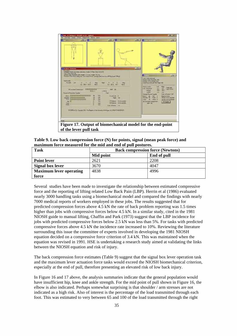
35
Figure 17. Output of biomechanical model for the end-point
of the lever pull task
Table 9. Low back compression force (N) for points, signal (mean peak force) and
maximum force measured for the mid and end of pull postures.
Back compression force (Newtons) Task
Mid point End of pull
Point lever 2621 2208
Signal box lever 3670 4047
Maximum lever operating
force
4838 4996
Several studies have been made to investigate the relationship between estimated compressive
force and the reporting of lifting related Low Back Pain (LBP). Herrin et al (1986) evaluated
nearly 3000 handling tasks using a biomechanical model and compared the findings with nearly
7000 medical reports of workers employed in these jobs. The results suggested that for
predicted compression forces above 4.5 kN the rate of back problem reporting was 1.5 times
higher than jobs with compressive forces below 4.5 kN. In a similar study, cited in the 1981
NIOSH guide to manual lifting, Chaffin and Park (1973) suggest that the LBP incidence for
jobs with predicted compressive forces below 2.5 kN was less than 5%. For tasks with predicted
compressive forces above 4.5 kN the incidence rate increased to 10%. Reviewing the literature
surrounding this issue the committee of experts involved in developing the 1981 NIOSH
equation decided on a compressive force criterion of 3.4 kN. This was maintained when the
equation was revised in 1991. HSE is undertaking a research study aimed at validating the links
between the NIOSH equation and risk of injury.
The back compression force estimates (Table 9) suggest that the signal box lever operation task
and the maximum lever actuation force tasks would exceed the NIOSH biomechanical criterion,
especially at the end of pull, therefore presenting an elevated risk of low back injury.
In Figure 16 and 17 above, the analysis summaries indicate that the general population would
have insufficient hip, knee and ankle strength. For the mid point of pull shown in Figure 16, the
elbow is also indicated. Perhaps somewhat surprising is that shoulder / arm stresses are not
indicated as a high risk. Also of interest is the percentage of the load transmitted through each
foot. This was estimated to very between 65 and 100 of the load transmitted through the right

36
foot. This has obvious implications for the quality of grip between foot and ground during these
operations. The coefficient of friction required varied between 0.5 for the mid point of the pull
to between 1.1 and 1.8 for the end point.
Modelling the posture recommended in the EWS Guide book (Figure 15), which represents an
early-mid point posture for the lever movement operation, and using the average peak and
absolute peak force values above in the biomechanical model produced estimated back
compression forces of 1667N and 3302N respectively.
It is important for the floor conditions to be high friction for this operation. This is partially the
case with the foot that is placed adjacent to the base of the lever, on the frame itself. This has a
profiled metal surface. The other foot remains positioned under the body so as to reduce the
likelihood of a slip or fall when at the full extent of the lever travel and in the most extreme
posture. This also assists the operator in standing up again.
7.2.3.2 Assessment summary
Overall, when comparing the lever operating forces that were measured, with guidelines for
force exertion based upon human strength data, and with the output of the biomechanical model,
the mean peak forces measured can exceed commonly accepted guidelines for force exertion.
Table 10. Summary of comparative pull force guidelines.
L23 20 kgf
MAFP Snook and Ciriello 69 kgf
BS EN 1005 11 kgf
Measured force values 42.9 kgf Points
80.5 kgf Signal box
The level of risk presented by such force requirements is therefore considered to be high to very
high.
7.2.4 Recommendations
Lever operation tasks should be the subject of manual handling/push-pull risk assessments;
Levers requiring notably high operating forces (say twice the L23 filter figure, i.e. 40kgf)
should be identified as such, and one means of dealing with them may be to employ a 2-
person operation where practicable;
Compatibility issues should be closely scrutinised in order to minimise the risks to
Signallers.
Lever operating forces should be reduced wherever possible, this may be achieved through
improved maintenance, and an investigation of the potential benefits of this is
recommended;
Floor conditions at levers should be good, and high friction.
7.3 SLEEPER CHANGING – WOODEN SLEEPERS
7.3.1 Description
The sequence of events in the sleeper changing process is as follows:
Delivery of replacement sleepers – not seen – this had taken place several days earlier. The new
sleepers had been dropped off by rail wagon (mechanically), and distributed in approximately

37
the right location for the replacements. In this case there was a ditch either side of the single
line.
7.3.1.1 Getting to the work site
The work site was approximately 1000m from the access point. The two rail trolleys were
pushed in to the work area. The first was pushed over the work area to its far end, and where the
work would start. The direction of work was to be back towards the access point. The other
trolley was pushed up close to the end of the work area, to be subsequently moved back towards
the access point as work progressed.
7.3.1.2 Preparation
The rail keys on all rail chairs through the length of the immediate work site are knocked out
with a keying hammer. The work site probably spanned some 300m.
The rail (bull head) at the sleepers to be replaced, is jacked up using Duff-Norton jacks, and
chocked (Figure 18). This is a forceful operation, and there is the risk that the lever will spring
back if the ratchet is not engaged fully when the operator releases pressure on the lever.
From observation, the force exerted by the worker appears to be significant. The posture and
technique adopted by the worker was that of pushing the lever downwards and across in front of
the body, starting in an erect posture and ending with up to 90 degree trunk flexion. The
worker’s body weight is used to push downwards in the final stages of the lever movement.
Figure 18(a) Preparatory digging . Figure 18(b) Jacking up of the rails using Duff-Norton rail jacks.
The ballast around the defective sleepers is dug away enough to loosen them and allow them to
be gripped with sleeper nips.
The chair screws were removed with a petrol nut-runner.
The rail chairs were lifted off and carried over to the new sleepers where they would be re-used.
7.3.1.3 Removing old sleepers
The defective sleepers were pulled out from under the tracks by a pair of workers using one pair
of sleeper nips. The sleepers were dragged off to the side of the single line (Figure 19). In places
there was a ditch with water along both sides of the line. The workers did this using sleeper nips
that had handles long enough for a two handed grasp. Occasionally a different pair of workers
used the small handled nips.

38
Figure 19. Two workers drag out the old sleepers.
7.3.1.4 Further preparation work
More ballast was dug away from the area where the sleepers had been removed in preparation
for the new sleepers.
The rail chairs were attached to the new sleepers with new screws – fastened with the nut-
runner.
7.3.1.5 Lifting in new sleepers
The new sleepers were lifted into position from the side of the track by a team of 6 or 5 workers.
Four lifted the sleeper and carried it the short distance necessary to its site (less than 5m), the
front end of the sleeper was then placed under the first rail, and set down (Figure 20). The front
set of workers then unfastened the nips and passed them to another pair of workers standing in
the 4-foot (or one worker moved over the rail and paired up with another). They then used the
nips to lift the sleeper the rest of the way and pass the front end under the opposite rail, working
with the back pair of workers from the first lift (Figure 21). This was achieved in a smooth and
controlled manner. It was clear that all the workers involved were clear on exactly what was to
be done and how and the lift was to be coordinated. The sleeper nips used in this operation (two
pairs) had handles only suitable for a one handed grasp.
It is worth noting that as the new sleepers have the rail chairs already fitted, the workers are
handling the additional weight of two rail chairs and 4 chair screws.

39
Figure 20. Four workers carry sleeper and place it
under the rail. Two workers stand-by in the 4ft to
take over lifting the front of the sleeper.
Figure 21. The two workers take over the nips at the
front of the sleeper and drag in right through under
the 2nd rail.
7.3.1.6 Positioning
Other workers then proceeded to position the rail using bars, and shovels to push back some of
the ballast.
NB: The sleepers were set later, when the whole team would pass back over the work area and
bed the sleepers in properly.
7.3.1.7 Dropping the rails
Typically several sleepers were replaced for every section of the tracks that were jacked up. The
rails were then dropped back after all workers had been instructed to stand clear. The Duff
Norton jacks let the rails drop suddenly, not in a controlled manner.
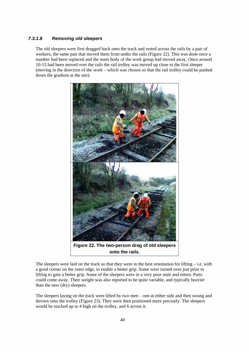
40
7.3.1.8 Removing old sleepers
The old sleepers were first dragged back onto the track and rested across the rails by a pair of
workers, the same pair that moved them from under the rails (Figure 22). This was done once a
number had been replaced and the main body of the work group had moved away. Once around
10-15 had been moved over the rails the rail trolley was moved up close to the first sleeper
(moving in the direction of the work – which was chosen so that the rail trolley could be pushed
down the gradient at the site).
Figure 22. The two-person drag of old sleepers
onto the rails.
The sleepers were laid on the track so that they were in the best orientation for lifting – i.e. with
a good corner on the outer edge, to enable a better grip. Some were turned over just prior to
lifting to gain a better grip. Some of the sleepers were in a very poor state and rotten. Parts
could come away. Their weight was also reported to be quite variable, and typically heavier
than the new (dry) sleepers.
The sleepers laying on the track were lifted by two men – one at either side and then swung and
thrown onto the trolley (Figure 23). They were then positioned more precisely. The sleepers
would be stacked up to 4 high on the trolley, and 6 across it.
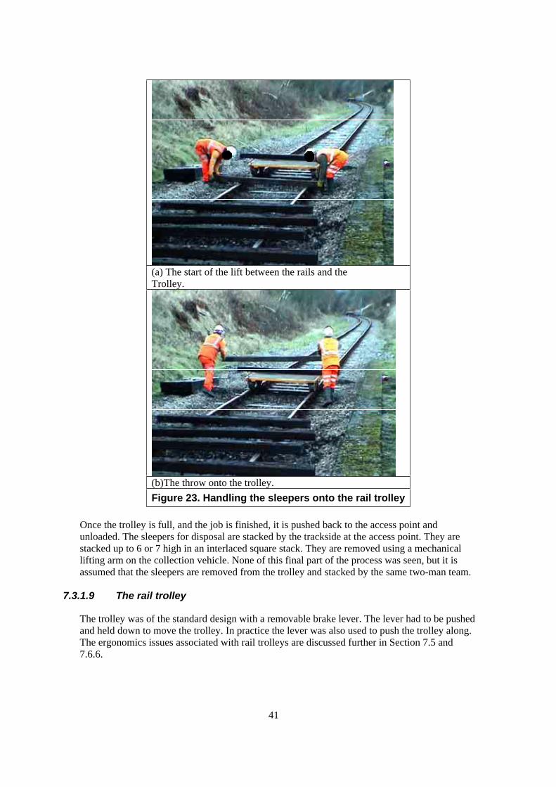
41
(a) The start of the lift between the rails and the
Trolley.
(b)The throw onto the trolley.
Figure 23. Handling the sleepers onto the rail trolley
Once the trolley is full, and the job is finished, it is pushed back to the access point and
unloaded. The sleepers for disposal are stacked by the trackside at the access point. They are
stacked up to 6 or 7 high in an interlaced square stack. They are removed using a mechanical
lifting arm on the collection vehicle. None of this final part of the process was seen, but it is
assumed that the sleepers are removed from the trolley and stacked by the same two-man team.
7.3.1.9 The rail trolley
The trolley was of the standard design with a removable brake lever. The lever had to be pushed
and held down to move the trolley. In practice the lever was also used to push the trolley along.
The ergonomics issues associated with rail trolleys are discussed further in Section 7.5 and
7.6.6.

42
7.3.2 Risk factors
7.3.2.1 Preparation
Knocking out keys - Repetitive use of a keying hammer (5.5kg) along the entire length of the
work area.
Jacking up of rail – the operating force on a Duff-Norton jack has not been assessed, but by
observation appears to be significant.
Digging ballast – the recommended digging technique it to use a knee to push on the shovel
handle. Shovel weight is typically 2.5kg, but a typical shovel full of ballast (not completely dry,
but not waterlogged) weighs up to around 8 kg. The total load handled is therefore around 12kg.
This is done in a stooping posture.
Removing chair screws with a petrol nut-runner - The torque on the nut runner has not been
measured. But its weight is known to be approximately 20kg from Company B’s plant list
weights booklet. Once it is in the upright position the operating and handling posture is
reasonable with the hands at around knuckle to elbow level. However, this depends on the
ground that the work is standing on in relation to the sleeper, and also its orientation.
Removing rail chairs – The rail chairs were lifted from ground level, to knuckle height, and
carried up to around 5m to where the replacement sleepers were located at the trackside. The
rail chairs being used at this site could not be found in the Weights of Plain Line Permanent
Way Materials booklet, but are estimated to weigh in at least 20kg each. The chairs were then
positioned on the sleepers ready for fastening with new chair screws.
7.3.2.2 Pulling out old sleepers
The weight of the old sleepers was reported to be variable depending upon their condition
(amount of rot, moisture content etc…). The weight of a new softwood sleeper is listed as 54kg.
It was reported that some of the old sleepers could be heavier than this.
The sleepers were gripped with the nips, outside the 4- foot and dragged from under the rails.
This was done with a one-handed lift and pull, typically from a stooped posture. Once the rail
had moved out approximately 0.5m, the grip with the nips was adjusted further towards the
centre of the sleeper, and the lift and pull repeated and sustained until the sleeper was well clear
of the track. The two workers did not support the entire weight of the sleeper, but lifted only one
end of it, the other dragging on the ballast. In some instances, the grip was moved again, further
towards the centre of the sleeper. The two workers would therefore be lifting and supporting
close to the full weight of the sleeper as well as exerting a dragging force. The magnitude of the
dragging force is unknown.
This operation was repeated periodically throughout the shift, as several sleepers were removed
and replaced in batches of 2 to 4.
7.3.2.3 Further preparation work
Digging out more ballast – as above.
Operating nut-runner – this involves lifting the machine from its usual resting position on the
ground, raising it to vertical operating orientation. Once in this position it can be lifted and
carried without stooping. Operating the machine involves supporting it (possibly off vertical, if

43
sleeper is not horizontal) and counteracting the torque of the device against the tightening
screw. Fitting screws involves stooping to near ground level to place them.
7.3.2.4 Lifting in new sleepers
The rail chairs being used at this site could not be found in the Weights of Plain Line Permanent
Way Materials booklet, but are estimated to weigh in the region of 20kg, each (x2). Chair
screws weigh approximately 1kg each (x4). The additional load is therefore approximately
44kg, making the total weight up to 100kg.
The lift and carry operation was performed with four workers supporting the load at any one
time. Carry distance around 5m over ballast.
The placement operation was performed with a mixture of lifting and dragging actions, with 4
workers acting at all times. The dragging forces exerted by the workers are unknown.
The lift, carry and placement operations were all well coordinated.
The sleeper nips used in this operation (two pairs) had handles only suitable for a one handed
grasp.
7.3.2.5 Dropping the rails
No manual handling risk factors.
7.3.2.6 Removing old sleepers to rail trolley
Drag from trackside onto rails – this is a drag rather than a full lift. At no time do the workers
support the full weight of the sleeper. The sleeper is pulled in this way for around 5m max. The
nips are used to grip the sleeper at around 30cm from the end. At this site some sleepers had to
be dragged up out of a ditch.
Lift from rails onto trolley – This is a full weight lift. The workers stand at either end of the
sleeper and stoop to grasp the underside, but because it is resting on the rails, the ends and
underside are easily accessible at a level of approximately 200mm above ground level. The
workers then tended to swing the sleeper across in front of their bodies and throw it onto the
trolley. They then repositioned the sleeper on the trolley to get a neat stack. The trolley was
moved along every 2 or 3 sleepers. The frequency of handling was approximately one sleeper
every 20 seconds or so during this period of repetitive lifting.
Push of fully laden trolley – this was not seen or measured. The trolley was very easy to push
when lightly laden, and when going with the gradient. Conventional wheeled trolley push/pull
force research suggests that the initial push pull force will be around 2% of the weight of the
load under favourable conditions. A full load of sleepers will be 6 x 4 = 24 sleepers x 54kg each
= 1296kg. If the same relationship applies, then the initial pushing force will be around 25kgf.
This is above the 20kg figure that HSE suggests as a filter figure for a detailed risk assessment.
The sustained propelling forces are unknown, but if there is an upward gradient to negotiate,
based upon a 1250kg load, the likely (minimum) forces can be calculated as follows:
Slope force = MgSin
(NB: assuming theoretical ideal conditions smooth track, no friction in bearings etc…)

44
Table 11. Calculated sustained pushing force for a rail trolley and sleepers.
Gradient Calculated force
(kgf)
1:300 4.2
1:200 6.4
1:150 8.4
1:100 12.7
These calculated sustained forces suggest that the forces required to propel the loaded trolley are
unlikely to exceed the L23 risk assessment filter figures for sustained pushing force application.
Lift from trolley onto stack at access point – this was not seen. It is highly likely that the
workers will adopt the same technique of tossing the sleepers onto the pile, and then positioning
more precisely by sliding.
Wooden sleepers are between 100 and 130mm deep. A stack height of 6 sleepers high means
that the hands will be lifting to between 500 and 650mm above ground level. This is below
knuckle height for even the smallest of workers.
The stack height of 4 on the trolley means that the hands will be lifting in the zone between
approximately elbow and knee level.
7.3.3 Assessment
7.3.3.1 The two-person pull of old sleepers
Although the actual force exerted by the two workers in the two-person pull of the old/defective
sleepers was not quantified, since the 54kg+ sleepers are partially lifted and supported as well as
being dragged with one arm only, the combination of force/load and posture is considered to
present a high risk of musculoskeletal injury. The same risks apply to the task of dragging the
old sleepers up to the rails before loading onto the rail trolley. The fact that the sleeper is being
dragged out from the under the rails is not considered to present a greater risk provided
sufficient ballast is removed prior to this operation.
7.3.3.2 The team lift and carry of new sleepers
The load lifted by the four-person team in this situation is understood to total at least 100kg.
This task is considered to present a moderate to high risk of musculoskeletal injury provided the
carry does not exceed about 10m. The design of the sleeper lifting nips could be improved upon,
to better enable workers to use both hands when lifting, and in terms of providing a more
comfortable handle for applying force through.
Although the force involved in moving the new sleeper was not quantified, the operation of
moving the new sleeper into place beneath the rails is considered to present a similar level of
risk, since the sleeper is being dragged rather than lifted and carried.
7.3.3.3 The two-person loading of the rail trolley
Although the lift from the top of the rails has advantages in terms of reducing the lift distance
and improving grip, because of the residual risk factors the lift of the old sleepers from the rail
to the trolley is still considered to present a high to very high risk of musculoskeletal injury due
45
to the weight lifted, the stooped posture at the start of the lift, the twist of the trunk, and the
relatively high frequency of lift (albeit for limited duration).
The pushing of the loaded trolley is considered to have the potential to present at least a
moderate risk of musculoskeletal injury. However, for the system of work seen during the site
visit, where two workers are available to perform the at least the initial push, the likely pushing
forces will be within accepted guidelines and the risk is consequently considered to be low.
The task of unloading the trolley at the access point was not observed, but it is considered likely
that this would present a high risk of musculoskeletal injury due to the load handled between
two workers, their likely postures, and the relatively high frequency of handling for the duration
of the operation.
7.3.4 Work organisation
The organisation of the work done in this job exemplifies the way in which planning and
forethought can make the job run smoothly and in helping to reduce the overall workload.
7.3.5 Recommendations
Consider using a mechanical sleeper changing machine – e.g. Geismar MRT, or make use of a
road-rail excavator where available. Please see section 5.4.5.1 on concrete sleeper replacement
for a detailed discussion.
The two-man pull out of old sleepers - Consider the use of mechanical aids to pull the sleeper
out from under the rails, e.g. a winch. Make this a four person operation. Provide sleeper nips
with handles large enough to enable both hands to grip. Plan the organisation of the work to
avoid creating obstacles to later process, i.e. avoid dragging sleeper out and into a ditch.
Two-man lift of old sleepers - While it is commendable that the workers first get the sleepers
onto the trolley and then adjust their position, the practice of throwing the sleepers across in
front of the body should be avoided when transferring the old sleepers between the track and the
trolley. If the trolley is moved close to the next sleeper after each is lifted, a controlled lift and
place operation can be performed.
7.3.6 Other issues arising
During this job (and at others also) the use of the Duff-Norton Rail Jack has been reported to be
problematic. Several workers reported being struck, or seeing others get struck by the handle of
the jack as it recoiled if the next notch on the ratchet was not engaged fully. It has been pointed
out to us that new recruits are often put on the jack, but that they need to be informed of the
danger. The way in which the jack releases its load instantaneously is also of some concern,
especially if the release can be triggered inadvertently.
7.4 SLEEPER CHANGING – CONCRETE SLEEPERS
The preparatory and finishing work for concrete sleeper replacement is exactly the same as for
wooden sleepers, the ballast is dug away, rail clips are removed using a pan-puller or a keying
hammer, the rails are jacked up and chocked. During the example we observed, the shoulder of
ballast was quite high, and this had to be dug away quite deeply to enable the sleepers to be slid
in from the Cess.
The method of moving the sleepers to the point of use was different however. A concrete
sleeper of this type (F40) will weigh around 284kg, and according to Company B’s risk
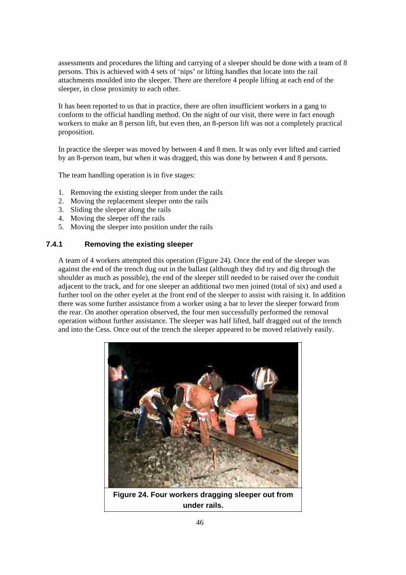
46
assessments and procedures the lifting and carrying of a sleeper should be done with a team of 8
persons. This is achieved with 4 sets of ‘nips’ or lifting handles that locate into the rail
attachments moulded into the sleeper. There are therefore 4 people lifting at each end of the
sleeper, in close proximity to each other.
It has been reported to us that in practice, there are often insufficient workers in a gang to
conform to the official handling method. On the night of our visit, there were in fact enough
workers to make an 8 person lift, but even then, an 8-person lift was not a completely practical
proposition.
In practice the sleeper was moved by between 4 and 8 men. It was only ever lifted and carried
by an 8-person team, but when it was dragged, this was done by between 4 and 8 persons.
The team handling operation is in five stages:
1. Removing the existing sleeper from under the rails
2. Moving the replacement sleeper onto the rails
3. Sliding the sleeper along the rails
4. Moving the sleeper off the rails
5. Moving the sleeper into position under the rails
7.4.1 Removing the existing sleeper
A team of 4 workers attempted this operation (Figure 24). Once the end of the sleeper was
against the end of the trench dug out in the ballast (although they did try and dig through the
shoulder as much as possible), the end of the sleeper still needed to be raised over the conduit
adjacent to the track, and for one sleeper an additional two men joined (total of six) and used a
further tool on the other eyelet at the front end of the sleeper to assist with raising it. In addition
there was some further assistance from a worker using a bar to lever the sleeper forward from
the rear. On another operation observed, the four men successfully performed the removal
operation without further assistance. The sleeper was half lifted, half dragged out of the trench
and into the Cess. Once out of the trench the sleeper appeared to be moved relatively easily.
Figure 24. Four workers dragging sleeper out from
under rails.

47
7.4.2 Moving the replacement sleeper onto the rails
The approach taken to moving the sleeper along the track to its point of use was to drag it from
the Cess and up onto the rails from where it had been dropped off mechanically. It was then
dragged along the rails relatively easily to its point of use. The sleeper was initially lifted from
its drop off position in the Cess, which was overgrown, and carried up over the shoulder to be
placed perpendicularly across the rails (the top of the rail is approximately 200m above the
ballast). This was not achieved in a single lift and carry, but in a number of short duration
exertions by the team of 8 workers. The operation was coordinated verbally by a person in
charge, leading a chant of ‘hey-up’ to coordinate the team’s effort. During the operation one of
the lifting handles became unattached during this carry, meaning that the sleeper was dropped,
nearly landing on one of the workers, and instantaneously loading the remaining 6 team
members more greatly. The weight of the sleeper shared between 6 is 47.3kg each, but it is the
remaining pair at that end of the sleeper will be loaded most, so the load on them is more likely
to become 71kg each).
(a). The initial lift of the replacement sleeper. (b) The carry up over the shoulder.
(c) The transfer onto the rails. (d) Dragging the sleeper along the rails.
Figure 25. The team handling of the replacement sleeper from the Cess onto the rails.
NB: Images taken using night vision equipment.

48
7.4.3 Moving the sleeper along the rails
Once sitting across both rails and supported on them, the sleeper was dragged along to its point
of use by at least 4 men. This appeared to be done with relatively little difficulty, although it
was not easy due to the poor underfoot conditions and the lateral direction of pull on the
handles.
7.4.4 Moving the sleeper off the rails, and moving the sleeper into position under the rails
The sleeper was then dragged off the rails into the Cess and then back under the rails into the
trench that had been dug out for it. Fine adjustment of its position was done by barring either
against the ground beneath the sleeper, or against the rails.
(a) Dragging the sleeper off the rails (b) Four men dragging the sleeper under the
rails.
Figure 26. The team handling of the replacement sleeper off the rails and back under the rails.
We had the opportunity to observe 2 sleepers being replaced in this manner. No force
measurements were taken during this exercise to quantify the efforts of the individuals involved,
and this would be difficult to achieve without additional instrumentation. However, the use of
the Borg RPE Scale may be informative, and this is recommended for future work.
For the two complete replacement operations that we were able to observe, the number of
individual lifts or dragging movements of the sleeper were 12 and 17. Each coordinated effort
lasted on average for approximately 3 to 4 seconds, and the total time that the team spent lifting,
supporting, carrying or dragging the sleeper for each operation was the same at 53 seconds. The
overall time taken to achieve the operation, starting from moving the sleeper from the Cess, to
its final position under the rails was between 3 min 15 sec to 5 min 17 sec.
7.4.5 Risk factors
7.4.5.1 Force
The weight of the sleeper in this instance was 284kg. Some sleepers that would be handled in
this way can weight up to 315kg.
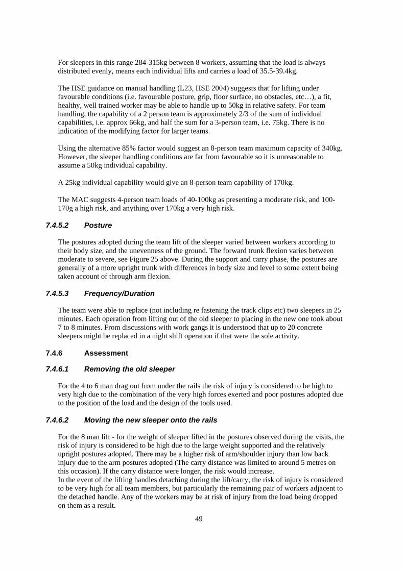
49
For sleepers in this range 284-315kg between 8 workers, assuming that the load is always
distributed evenly, means each individual lifts and carries a load of 35.5-39.4kg.
The HSE guidance on manual handling (L23, HSE 2004) suggests that for lifting under
favourable conditions (i.e. favourable posture, grip, floor surface, no obstacles, etc…), a fit,
healthy, well trained worker may be able to handle up to 50kg in relative safety. For team
handling, the capability of a 2 person team is approximately 2/3 of the sum of individual
capabilities, i.e. approx 66kg, and half the sum for a 3-person team, i.e. 75kg. There is no
indication of the modifying factor for larger teams.
Using the alternative 85% factor would suggest an 8-person team maximum capacity of 340kg.
However, the sleeper handling conditions are far from favourable so it is unreasonable to
assume a 50kg individual capability.
A 25kg individual capability would give an 8-person team capability of 170kg.
The MAC suggests 4-person team loads of 40-100kg as presenting a moderate risk, and 100-
170g a high risk, and anything over 170kg a very high risk.
7.4.5.2 Posture
The postures adopted during the team lift of the sleeper varied between workers according to
their body size, and the unevenness of the ground. The forward trunk flexion varies between
moderate to severe, see Figure 25 above. During the support and carry phase, the postures are
generally of a more upright trunk with differences in body size and level to some extent being
taken account of through arm flexion.
7.4.5.3 Frequency/Duration
The team were able to replace (not including re fastening the track clips etc) two sleepers in 25
minutes. Each operation from lifting out of the old sleeper to placing in the new one took about
7 to 8 minutes. From discussions with work gangs it is understood that up to 20 concrete
sleepers might be replaced in a night shift operation if that were the sole activity.
7.4.6 Assessment
7.4.6.1 Removing the old sleeper
For the 4 to 6 man drag out from under the rails the risk of injury is considered to be high to
very high due to the combination of the very high forces exerted and poor postures adopted due
to the position of the load and the design of the tools used.
7.4.6.2 Moving the new sleeper onto the rails
For the 8 man lift - for the weight of sleeper lifted in the postures observed during the visits, the
risk of injury is considered to be high due to the large weight supported and the relatively
upright postures adopted. There may be a higher risk of arm/shoulder injury than low back
injury due to the arm postures adopted (The carry distance was limited to around 5 metres on
this occasion). If the carry distance were longer, the risk would increase.
In the event of the lifting handles detaching during the lift/carry, the risk of injury is considered
to be very high for all team members, but particularly the remaining pair of workers adjacent to
the detached handle. Any of the workers may be at risk of injury from the load being dropped
on them as a result.
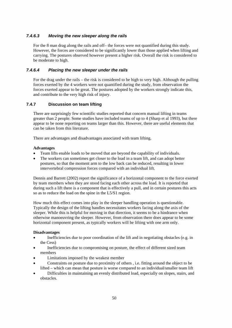
50
7.4.6.3 Moving the new sleeper along the rails
For the 8 man drag along the rails and off– the forces were not quantified during this study.
However, the forces are considered to be significantly lower than those applied when lifting and
carrying. The postures observed however present a higher risk. Overall the risk is considered to
be moderate to high.
7.4.6.4 Placing the new sleeper under the rails
For the drag under the rails – the risk is considered to be high to very high. Although the pulling
forces exerted by the 4 workers were not quantified during the study, from observation the
forces exerted appear to be great. The postures adopted by the workers strongly indicate this,
and contribute to the very high risk of injury.
7.4.7 Discussion on team lifting
There are surprisingly few scientific studies reported that concern manual lifting in teams
greater than 2 people. Some studies have included teams of up to 4 (Sharp et al 1993), but there
appear to be none reporting on teams larger than this. However, there are useful elements that
can be taken from this literature.
There are advantages and disadvantages associated with team lifting.
Advantages
Team lifts enable loads to be moved that are beyond the capability of individuals.
The workers can sometimes get closer to the load in a team lift, and can adopt better
postures, so that the moment arm to the low back can be reduced, resulting in lower
intervertebral compression forces compared with an individual lift.
Dennis and Barrett (2002) report the significance of a horizontal component to the force exerted
by team members when they are stood facing each other across the load. It is reported that
during such a lift there is a component that is effectively a pull, and in certain postures this acts
so as to reduce the load on the spine in the L5/S1 region.
How much this effect comes into play in the sleeper handling operation is questionable.
Typically the design of the lifting handles necessitates workers facing along the axis of the
sleeper. While this is helpful for moving in that direction, it seems to be a hindrance when
otherwise manoeuvring the sleeper. However, from observation there does appear to be some
horizontal component present, as typically workers will be lifting with one arm only.
Disadvantages
Inefficiencies due to poor coordination of the lift and in negotiating obstacles (e.g. in
the Cess)
Inefficiencies due to compromising on posture, the effect of different sized team
members
Limitations imposed by the weakest member
Constraints on posture due to proximity of others , i.e. fitting around the object to be
lifted – which can mean that posture is worse compared to an individual/smaller team lift
Difficulties in maintaining an evenly distributed load, especially on slopes, stairs, and
obstacles.

51
From the literature (Pinder et al 1997, Boocock 1997, Monnington 2000, EN 1005 Part 2) there
is a general acceptance that there is a loss of efficiency associated with team handling,
compared to the sum of individual capabilities. For studies of teams of up to 4 people, there is
evidence that team lifting capability is approximately 85% of the sum of individual capabilities.
This figure is consistent between studies of various team sizes up to 4 people. It is considered
unlikely that larger teams will be more efficient, and more likely that efficiency will drop off as
team size increases, coordination becomes more difficult, space around the object becomes
cramped, and obstacles become more difficult to negotiate.
In terms of the 8-person team lift associated with concrete sleeper handling, the close proximity
of the workers to each other when using the lifting handles, the difficulty in walking on the
ballast, on a slope and stepping over the rails all add to the risks involved.
When moving on the sloping ballast and crossing the rails the team do not appear to able to
share the load evenly between them at all times.
7.4.8 Dragging versus Lifting
The pulling task, while the forces applied have not been quantified, from observation it is
considered to present a lower risk than would the lifting of the sleeper, provided that the sleeper
dragged in a controlled manner.
The underfoot conditions at the trackside, and on the ballast and sleepers is very uneven,
overgrown, slippery and unstable. The operation of applying a pulling force presents a high risk
of musculoskeletal injury, but also slipping, tripping and falling, compared with lifting and
carrying. The consequence of slip, trip, or fall in the situation of a controlled team pull is
considered to present a lower risk of injury for the person who falls – they cannot have the
sleeper fall on them, and for the other members of the team – who although loaded more greatly
as a result of the loss of contribution from the fallen team member, do not need to support the
load.
The practice of moving the load in a series of bursts of exertion with the chant of ‘hey-up’, may
also serve to reduce the risks arising from members of the team dropping out, because of the
short duration. If someone does fall it is likely that they will have contributed some effort to the
team before falling. The down side is that the movement of the item is not controlled closely
during each effort, so if someone did fall in its path, it is unlikely that the team would be able to
stop the item moving in time to prevent injury.
7.4.9 Recommendations
Due to the high risks of injury associated with the manual handling of sleeper, efforts should be
made to avoid, where practicable, the lifting of heavy concrete sleepers. The following
suggestions of possible control measures should be considered:
7.4.9.1 Mechanical handling of sleeper for replacement operations.
There are a wide range of machines (such as the Geismar MRT, and the Harsco Track
Technologies sleeper handlers) that can replace all types of sleepers mechanically (Figure 27).
The whole of the sleeper handling and movement is achieved mechanically, and can apparently
be achieved without jacking the rails.

52
Figure 27. An example of a mechanical sleeper replacement machine.
(Source: Geismar catalogue)
For dual line working, it would seem possible for the sleeper to be moved mechanically by
a road/rail excavator. There are specialised attachments available. However it would seem that a
road/rail excavator might be used even without a specialised attachment. For dragging the
sleepers in and out of position under the rails in replacement work, it would be necessary for the
excavator lifting hook/eye to be quickly disconnected and reconnected as the sleeper is moved
under the first and then the second rail. This could be done using a means of attaching into the
eyelets, similar to the nips used for the manual operation – perhaps utilising a scissor action to
ensure that the pins remain located in the eyelets.
For single line working, we have not established whether the range of reach of an excavator
is suitable for this work, given that the rail needs to be jacked, and pandrol clips removed for
some distance either side of the replacement. However, if an excavator is being used at the site
it could at least be used (before the rails are jacked) to position the replacement sleepers ready
for manual movement into final position. This could mean that only a single manual drag would
be necessary.
7.4.9.2 Alternative mechanical aids
It is envisaged that a portable powered or even manual winch might be used to pull the
sleepers from the Cess and under the raised rails. In dual line working this might be attached to
the adjacent line in some way (so long as this does not cause damage). Alternatively there may
be some suitable means of anchoring. In addition, portable (vacuum) handling equipment is in
routine use in the construction sector for handling kerbstones, blocks and slabs, and this
equipment is considered likely to be applicable to track working.
7.4.9.3 For continued manual replacement
In the short-term, if mechanical assistance is not considered practicable:
Generic risk assessments for manual handling operations such as team sleeper handling
must be supplemented with site specific assessments, as the local working conditions have a
large effect on the level of risk involved.

53
Ensure that the sleepers are dropped off accurately at the point of use. This may mean that
sleepers for replacement need to be marked in a different way so that the operator of the
delivery vehicle can identify location accurately. Although this would not avoid the
handling operation altogether, it would significantly reduce the amount of manual handling
associated with each sleeper. The orientation of the sleepers is also important. They should
always be the right way up.
Ensure that sufficient ballast is dug away to enable the old and new sleepers to be moved as
easily as possible.
Ensure that the necessary number of personnel are available as indicated in the risk
assessment, and that they follow the prescribed system of work.
The practice of dragging in place of lifting appears should be encouraged. On the basis of
observations the practice of moving the sleepers longer distances manually along the rails
by dragging is preferable to a lift and carry in terms of minimising the risk of
musculoskeletal injury. This practice appears to offer some benefits in terms of reducing the
forces involved and therefore the loads on the individual workers. It has not been possible to
quantify this as part of this study. On the basis of observation, the dragging approach is
recommended in place of a lift wherever practicable, primarily because the entire mass of
the sleeper is not being supported and therefore it is less likely to fall and injure someone –
and with the appropriate number of personnel required for a lift of the same object.
However, it would seem that dragging is not without risk and if it is a practice that can be
used widely, then further work is required to determine the risks more precisely, develop an
appropriate system of work and tools specifically designed for it (for dragging, the
alternative tool position shown in Figure 28(b) below is probably appropriate). The practice
will need to be addressed in training.
Quantification of the loads placed on individual workers during dragging is required in
order to better understand the risks and establish the number of personnel required to make
a drag in relative safety (given that the overall force required to drag a sleeper appears to be
reduced compared with lifting and carrying). This might be most easily achieved by using
instrumentation during a mechanical dragging operation to simulate the conditions of
moving a sleeper though ballast, and on the rails.
Undertake an appraisal of the design of the sleeper handling tool – see below.
7.4.9.4 The sleeper lifting tool
The lifting handles used popped out of the sleeper eyelets on several occasions during the two
sleeper movements that we observed. The result is that the workers pulling on the nips at the
time stumble forward out of control, while the rest of the team are instantaneously loaded more
greatly. The reason for this failure was not established. It could be a result of wear/damage,
inadequate design, or other factors. Poor coordination and control during a team movement
could give rise to lateral force on the tool, which is considered to be especially likely when the
sleeper is being dragged, and or catches on an obstacle. A positive locating/locking mechanism
is therefore recommended.
The sleeper lifting tool can be used in two configurations. The configuration most used is
believed to be that shown in Figure 28(a) above. The tool can be used in a manner which allows
more space between the workers (Figure 28(b)) and to some extent the tool may locate

54
positively in this orientation. However, the tool is free to rotate on its axis in this position,
which may present some problems in practice. Unfortunately we have not been able to observe
this method in use.
(a) The typical orientation of the tool for sleeper
lifting and carrying
(b) The alternative orientation which may allow
more space between team members, and may also
be more appropriate for some dragging operations.
Figure 28. The sleeper lifting tool in the typical and alternative positions.
This type of tool is therefore not considered to be suitable for this job: If the workers cannot
trust in the tool:
They will not be inclined to exert to their full capacity;
They may adopt postures that are less suitable for the lifting element in anticipation of
the tool releasing;
The instantaneous loading on the rest of the team increases the risks to them;
The resulting stumbles are likely to lead to fall injuries and could easily result in serious
injury of the sleeper is subsequently dropped on the fallen person.
7.4.10 Recommendations
The design of the tool should be critically reviewed with the aim of making improvements:
The characteristics of the tool should more closely match the requirements of the
workforce in terms of its suitability for lifting and dragging operations, its size to enable
optimal lifting posture, handle dimensions, etc…
A means of enabling workers lift and carry without being in such close proximity;
The tool should locate positively in the sleeper, and be able to withstand uneven loading
without disengaging;
The relative advantages and disadvantages to workers of lifting/moving sleepers in the
two possible orientations should be investigated;
7.5 UNLOADING/LOADING OF TOOLS AND EQUIPMENT
7.5.1 Handling of rail trolleys
Two types of rail trolley are shown being unloaded in Figure 29 below, a half-size link trolley
weighing approximately 54kg is being carried by two workers, and a 2 tonne capacity trolley
being carried by 4 workers weighing 124kg.
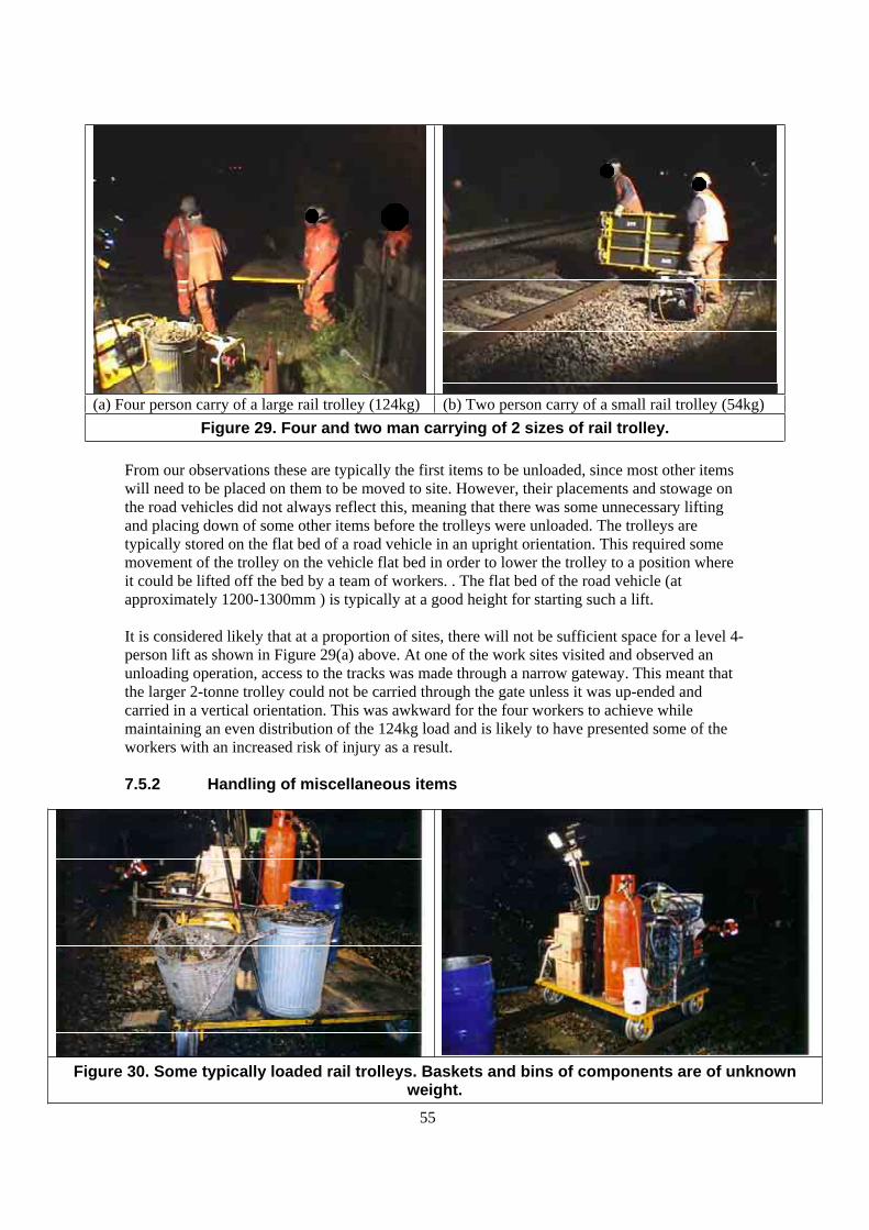
55
(a) Four person carry of a large rail trolley (124kg) (b) Two person carry of a small rail trolley (54kg)
Figure 29. Four and two man carrying of 2 sizes of rail trolley.
From our observations these are typically the first items to be unloaded, since most other items
will need to be placed on them to be moved to site. However, their placements and stowage on
the road vehicles did not always reflect this, meaning that there was some unnecessary lifting
and placing down of some other items before the trolleys were unloaded. The trolleys are
typically stored on the flat bed of a road vehicle in an upright orientation. This required some
movement of the trolley on the vehicle flat bed in order to lower the trolley to a position where
it could be lifted off the bed by a team of workers. . The flat bed of the road vehicle (at
approximately 1200-1300mm ) is typically at a good height for starting such a lift.
It is considered likely that at a proportion of sites, there will not be sufficient space for a level 4-
person lift as shown in Figure 29(a) above. At one of the work sites visited and observed an
unloading operation, access to the tracks was made through a narrow gateway. This meant that
the larger 2-tonne trolley could not be carried through the gate unless it was up-ended and
carried in a vertical orientation. This was awkward for the four workers to achieve while
maintaining an even distribution of the 124kg load and is likely to have presented some of the
workers with an increased risk of injury as a result.
7.5.2 Handling of miscellaneous items
Figure 30. Some typically loaded rail trolleys. Baskets and bins of components are of unknown weight.
56
The weights of many items that are transferred between road vehicles and the rail trolleys are
known, including the rail trolleys themselves. These can be included in risk assessment, and the
handling planned for an appropriate sized team. However, there are also a number of items for
which the weight is not known (i.e. not listed in Company B’s Plant List Weight booklet). These
include:
Large Propane Gas cylinders (46kg capacity)
Bins/baskets of components
Boxes of components
Buckets and tins of materials
For example the weight of the dustbin full of rail clips (Figure 30) is likely to be significant. The
bin only has two handles, each only large enough for one hand. It is considered likely that the
weight could warrant at least two workers to lift it, yet actually achieving this will be quite
difficult.
As part of the risk assessment process, there is a need to examine these practices and to quantify
the weights and assess the risks to workers. At least if the weights (or weight range) of bins used
for carrying certain components are known, a suitable means of handling them can be devised,
and/or the bins can be modified accordingly.
We observed two workers handling a large 46kg gas capacity propane cylinder between a truck
and a rail trolley (Figure 30). The empty weight of these can vary between cylinders of the same
capacity. For the size seen during the visit, the weight varies as follows: 32-65kg empty, to 76-
111kg full. Pinder (1999).
Given this degree of variation, the risk of low back injury presented to two workers by handling
the cylinder ranges from low to very high (Comparing these load figures with the MAC). It is
therefore important to know the weight of these cylinders (perhaps within a limited range) at
any particular time in order to decide on an appropriate means of handling. In addition, Pinder
(1999) recommends that cylinders above the 15kg capacity type (27-35kg full) should not be
handled manually by individuals.
7.5.3 Recommendations
The unit weight of many of the generic ‘packages’ of items loaded and unloaded should be
established, listed and indicated on them.
Provide greater uniformity of containers and packages, including uniformity in terms of the
handles provided, their design, location and number, appropriate to the number of persons
required to lift and handle in relative safety.
Consider using smaller unit packages, such as smaller drums and bins to control the
maximum weights handled at any one time.
Consider using smaller gas cylinders.
7.6 USE OF SELECTED TOOLS AND EQUIPMENT
While it has not been possible to make detailed ergonomics appraisals of the tools used in track
maintenance work, the following observations have been made during the site visits.
7.6.1 Rail profile grinder
The tool was a Geismar Rail Profile Grinding Machine MP12. This is used to re-profile the rail
head and sides after thermite welding (Figure 31).

57
Figure 31. Two typical postures illustrating the range of trunk flexion involved in the grinding operation.
The manufacturers information for this device states that the machine is well balanced in all
positions (it is tilted over to each side of the rail to grind the side of the rail head). It has wheels
that grip the rail and hold it against the rail in all positions. It can be fitted with an outrigger that
can support the device at varying inclinations.
The grinder is fitted with a large grab handle (840mm high) that provides plenty of room for
changes in grip during use and for steadying during lifting the device between two people
(Figure 32).
Figure 32. The lifting and carrying of the grinder over the rails. Note that one worker lifts with one arm in both cases.
The machine being used was not fitted with an outrigger, so the operator supported the grinder
at varying angled down to approximately 90 degrees from upright, on each side of the rail.
7.6.1.1 Risk Factors
Force
The catalogue weight is 67kg. Company B’s Plant List Weight Guide lists a Stumec rail profile
grinder with a weight of 72kg. We measured the force required to support each end of the
grinder in a two person lift. One end required 31.8kg, the other 44.3kg. It therefore appears that
58
the weight distribution between the lifting team members is uneven. In Figure 32 above the
operator lifting with one hand is at the heaviest end of the tool.
The grinder was lifted from the bed of the panel van onto the ground. It was then lifted by two
men and carried approximately 5 metres to the work area. Once one side of the rail had been
profiled satisfactorily, the grinder was lifted by two men again and turned through 180 degrees.
The force exerted by the operator during the grinding operation would be more difficult to
ascertain, but it is possible to make some estimations: Based upon the assumption that the
grinder is held at an angle of 45 degrees, its weight is 70kg and the centre of gravity is located
approximately one third of way up the height of the grinder, the estimated supporting force
when the grinder is the position shown in Figure 31 is approximately 16.5kg.
The supporting force is provided at the hip, and acts in an upward and forward direction as the
operator rested the handle against his upper thigh and leant over it. There is also an additional
horizontal component as the operator pushes the grinder against the side of the rail, but his has
not been quantified.
Posture
From an analysis of the video footage for this task for posture, the operator spends
approximately 80% of the task duration with trunk flexion of between 45 and 90 degrees, and
20% with a trunk flexion greater than 90 degrees. Some support for the trunk appears to be
provided from the arms.
Repetition
Based upon the requirements for the shift that we observed, the grinding operation would need
to be repeated at least twice in a shift as part of this kind of repair work.
Duration
The task lasted approximately 10 minutes. Additional time was taken up by lifting, carrying and
turning the grinder.
7.6.1.2 Assessment
The grinder lifting operation
Comparing the weight of the grinder at approximately 70kg, lifted between two workers, with
the figures for team handling in the HSE Manual Handling Assessment Charts (HSE 2003), the
operation is classed as high risk (red), and may expose a significant proportion of the working
population to a risk of injury. The additional factors of the vertical lift region, any trunk
twisting, and the poor underfoot conditions all add to the overall risk of injury.
The grinding operation
The forces exerted during the grinding operation are largely unquantified. The estimated
supporting force of 16.5kg is significant, but this is provided at the hip rather than the exerted
with the hands. It is therefore difficult to make a judgement about the risk presented by the
forces applied during the operation.
However, the posture alone is considered to present a high risk of injury, as although there
appears to be some support provided by the arms during some of the operation, the loading on
the spine involved in supporting the body in these postures is high.

59
7.6.1.3 Recommendations
Undertake a detailed assessment of the risks involved in this work activity, including
quantification of the forces involved.
In the short-term the use of the outrigger to support the tool in operation is recommended.
Review the design of the grinders available to reduce the amount and duration of forward
trunk flexion required, reduce the forces applied and to make the grinder lighter and easier
to lift and carry. There are equivalent grinders available that avoid the need to bend over
and support the device to such an extent, and these may present a significantly lower risk.
For example the Stanley PG10 has a mechanism whereby the operator remains stood
upright throughout the grinding operation Figure 33. It is also powered by compressed air
reducing the weight to 53kg.
Rotate workers between this operation and other tasks where there is an opportunity for
recovery, i.e. tasks not involving severe forward trunk flexion. Rotation between workers
during the operation should also be considered.
Figure 33. The Stanley PG10in operation.
Source: Stanley Tools.
7.6.2 Nut-runner
The use of the nut-runner is a generic task. The use of nut runners was observed at Ebbw
Junction, Sugarloaf Halt. On these occasions the nut-runner has only been seen to be used on
chair screws (Figure 34), but it was observed to be used to tighten/loosen fishplate bolts, in a
horizontal orientation (Figure 35).

60
Figure 34. Working postures during use of the same model of nut-runner.
Figure 35. Nut runner used to fasten
Fishplate bolts.
Weight
The Company B Plant List Weights booklet indicates that this type of device can weigh around
20kg.
Force
The forces exerted by the worker in resisting the rotation of the tool are not known. When the
tool is used in the upright position (vertical orientation) it is unlikely that significant force is
exerted in supporting the tool. There may be some downward force exerted in ensuring that the
tool remains located on the chair screw, but the weight of the tool itself is likely to fulfil this
function, and any additional force is easy to provide using body mass. When used in the
horizontal orientation as shown in Figure 35. the supporting force is likely to be significant, and
close or equal to the total weight of the tool. There will also be a horizontal component exerted
to keep the tool engaged on the fishplate bolt head / nut.
Posture
When used in the vertical orientation, the posture of the worker will be influenced by their body
size and the location of the bolt head. The right hand image probably represents the most typical
situation, where the bolt is located at ground level.

61
When used in the horizontal orientation, the working posture of the operator is poor. There is
forward trunk flexion of up to 90 degrees and this is held statically until the nut is tight. Repetition / Duration
It is not known what the typical repetition rate would be for using this tool intensively. During
the site visits made, use was intermittent.
Vibration
Vibration is a known risk factor for carpal tunnel syndrome. The vibration characteristics of the
tool are not known.
7.6.2.1 Assessment
Using this tool in the vertical orientation is considered to present a moderate risk due to
the combination of its weight and the relatively upright postures that can be adopted
during use.
Carrying between points of use is considered to present a low to moderate risk of injury
due to the weight of the tool and the difficulty of carrying it symmetrically over longer
distances.
The use of the tool in the horizontal orientation presents a high risk of injury due to the
combination of its weight, the severely stooped postures associated with its use, and the
need to lift the tool in and out of these positions.
7.6.2.2 Recommendations
Using this tool in a horizontal orientation to tighten fishplate bolts is not recommended.
Even if the tool can be supported on the ground, this would still present a high risk of
injury due to the postural issues. There is also the consideration of the handling activity
associated with moving the tool from one point of use to the next. The operation will
involve handling a 20kg load at between knee and ground level.
Angled and long handled nut runners are available for applications such as fishplate bolt
work and can avoid the need for the operator to stoop (Figure 36).
As there appears to be tendency for worker to stoop during use, the tool may be
improved with the addition of handles that would enable workers to avoid stooping.
There was not sufficient opportunity within this study to make a more detailed appraisal
of the design.
A shoulder strap may assists in carrying the tool, but when it is being used intensively
or moved over long distances a rail scooter or trolley may be more appropriate.
Simple long handled spanners or wrenches may be more appropriate for tasks like fish
plate tightening. They are lighter in weight, do not vibrate, are quiet, and allow an
upright posture.
The decision regarding what tools to use on a job is made at a local level and it is
important that safety and health issues are balanced with productivity. It is therefore
important that the team leaders have the appropriate knowledge to make such decisions,
and this should be provided in both technical and manual handling training.
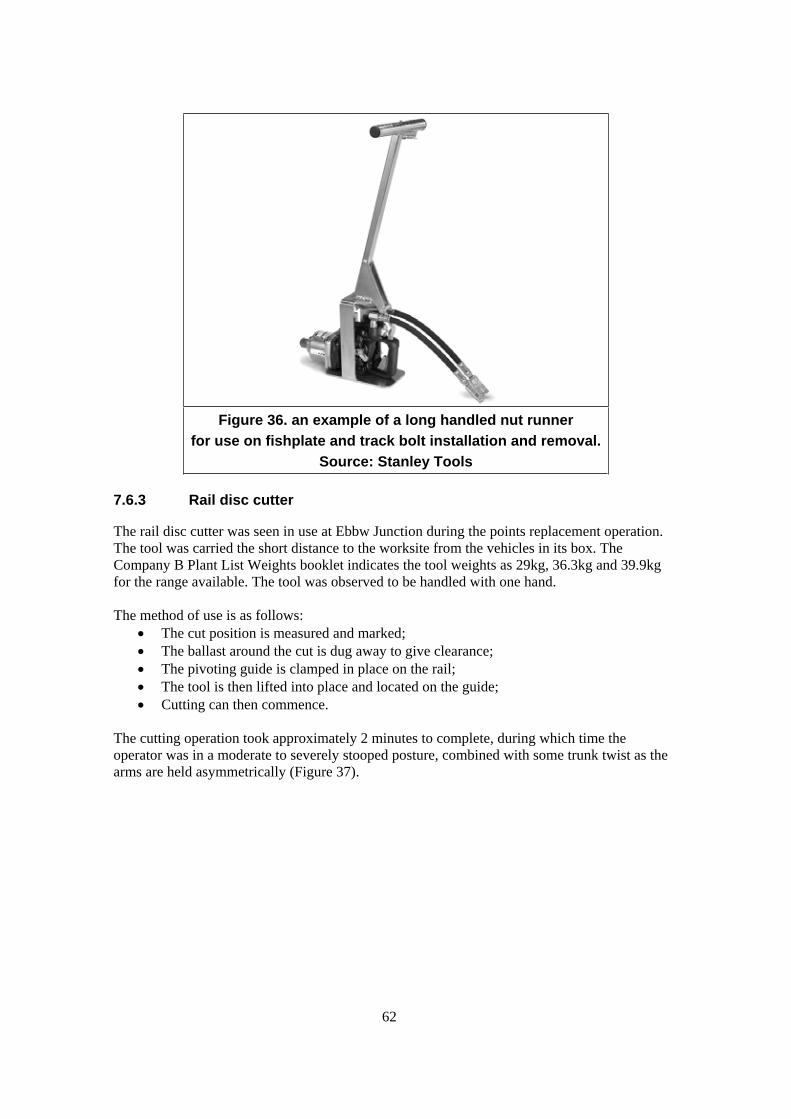
62
Figure 36. an example of a long handled nut runner
for use on fishplate and track bolt installation and removal.
Source: Stanley Tools
7.6.3 Rail disc cutter
The rail disc cutter was seen in use at Ebbw Junction during the points replacement operation.
The tool was carried the short distance to the worksite from the vehicles in its box. The
Company B Plant List Weights booklet indicates the tool weights as 29kg, 36.3kg and 39.9kg
for the range available. The tool was observed to be handled with one hand.
The method of use is as follows:
The cut position is measured and marked;
The ballast around the cut is dug away to give clearance;
The pivoting guide is clamped in place on the rail;
The tool is then lifted into place and located on the guide;
Cutting can then commence.
The cutting operation took approximately 2 minutes to complete, during which time the
operator was in a moderate to severely stooped posture, combined with some trunk twist as the
arms are held asymmetrically (Figure 37).
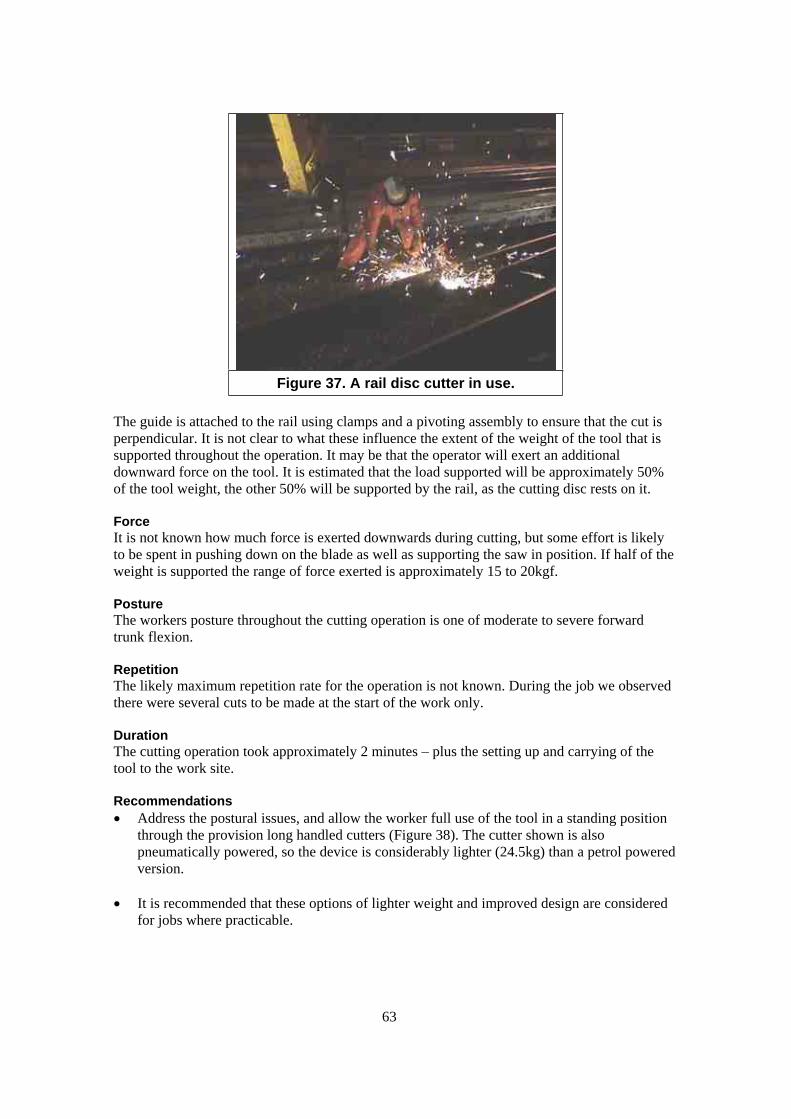
63
Figure 37. A rail disc cutter in use.
The guide is attached to the rail using clamps and a pivoting assembly to ensure that the cut is
perpendicular. It is not clear to what these influence the extent of the weight of the tool that is
supported throughout the operation. It may be that the operator will exert an additional
downward force on the tool. It is estimated that the load supported will be approximately 50%
of the tool weight, the other 50% will be supported by the rail, as the cutting disc rests on it.
Force
It is not known how much force is exerted downwards during cutting, but some effort is likely
to be spent in pushing down on the blade as well as supporting the saw in position. If half of the
weight is supported the range of force exerted is approximately 15 to 20kgf.
Posture
The workers posture throughout the cutting operation is one of moderate to severe forward
trunk flexion.
Repetition
The likely maximum repetition rate for the operation is not known. During the job we observed
there were several cuts to be made at the start of the work only.
Duration
The cutting operation took approximately 2 minutes – plus the setting up and carrying of the
tool to the work site.
Recommendations
Address the postural issues, and allow the worker full use of the tool in a standing position
through the provision long handled cutters (Figure 38). The cutter shown is also
pneumatically powered, so the device is considerably lighter (24.5kg) than a petrol powered
version.
It is recommended that these options of lighter weight and improved design are considered
for jobs where practicable.

64
Figure 38. A long handled disc cutter
(Source: Stanley Tools)
7.6.4 Sleeper and Rail lifting nips
Figure 39. Rail lifting ‘dogs’.
Typical rail nip dimensions
Width across handles - 875mm
Handle length - 165mm
Handle diameter - 22mm
Length pivot to handle - 320mm
Length pivot to base – 150mm
In use, the height of the handle will be approximately 580mm above the ground (assuming the
rail section to be lifted is resting on the ground). Standing knuckle height (shod) for British
Males is in the range 735-870mm (5th – 95th centile). Knee-cap height is in the range 490-
575mm (5th - 95th centile). The handle of the nips will therefore be above knee level for most
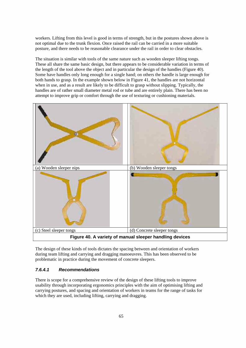
65
workers. Lifting from this level is good in terms of strength, but in the postures shown above is
not optimal due to the trunk flexion. Once raised the rail can be carried in a more suitable
posture, and there needs to be reasonable clearance under the rail in order to clear obstacles.
The situation is similar with tools of the same nature such as wooden sleeper lifting tongs.
These all share the same basic design, but there appears to be considerable variation in terms of
the length of the tool above the object and in particular the design of the handles (Figure 40).
Some have handles only long enough for a single hand; on others the handle is large enough for
both hands to grasp. In the example shown below in Figure 41, the handles are not horizontal
when in use, and as a result are likely to be difficult to grasp without slipping. Typically, the
handles are of rather small diameter metal rod or tube and are entirely plain. There has been no
attempt to improve grip or comfort through the use of texturing or cushioning materials.
(a) Wooden sleeper nips (b) Wooden sleeper tongs
(c) Steel sleeper tongs (d) Concrete sleeper tongs
Figure 40. A variety of manual sleeper handling devices
The design of these kinds of tools dictates the spacing between and orientation of workers
during team lifting and carrying and dragging manoeuvres. This has been observed to be
problematic in practice during the movement of concrete sleepers.
7.6.4.1 Recommendations
There is scope for a comprehensive review of the design of these lifting tools to improve
usability through incorporating ergonomics principles with the aim of optimising lifting and
carrying postures, and spacing and orientation of workers in teams for the range of tasks for
which they are used, including lifting, carrying and dragging.

66
Figure 41. Demonstration of the wooden sleeper
tongs.
7.6.5 Rail jacks
The rail jacks used by every crew that we observed during this study were Duff Norton ratchet
jacks, see Figure 42. However, there are two design variations, a new and old version. The main
difference between the two versions is the handle, the handle on the older models was reported
to be the preferred choice by several workers. NB: Of the two pictured here, the old style is a
lighter weight and lower capacity model.
(a) Old design (light weight low capacity)
24kg.
(b) New design (high capacity) 31kg.

67
(c) Hand/arm posture when lifting using the
handle.
(d) Hand/arm posture when using the curved
handle.
Figure 42. The Duff Norton rail jack models in use currently, showing the variation in handle design.
7.6.5.1 Handle design
In terms of one-handed carrying as shown above the old design of handle was preferred by all
workers who expressed a preference (Figure 42(a) and (c)). The main complaint was that the
new handle is too short, it is curved, and it has mouldings (probably intended to fit the
indentations between the fingers).
The handle orientation on the newer design is arguably better since the hand is held in
apposition at the approximate mid point of the range of rotation of the forearm, whereas the
older version means that the forearm is rotated close to the full extent of movement. It is
therefore the specific problems with the handle length and shape that are in question.
These jacks clearly have two load bearing surfaces for lifting, however, only the lower load
surface was used in rail jacking operations. If the top load surface is rarely used in track
maintenance work, perhaps a design of jack more specific to rail jacking should be selected, that
does not have some of the problems that workers report.
7.6.5.2 One handed lifting and carrying
The HSE guidance on manual handling operations makes little mention of handling at the side,
and there is relatively little research on the subject. However, lifting capacity at the side is
known to be reduced compared with symmetrical two handed lift in front of the body. Lee et al
(1990) established a mean Maximum Acceptable Weight of Lift (MAWL) at the side of 11.5kg
(i.e. 50th centile male capability). Comparing this figures with the weight range of the Duff
Norton jacks suggests that the weight alone presents a high risk of injury.

68
Guidelines for carrying operations mainly concern symmetrical load carrying with both hands.
Comparing the one-handed jack carry task with the MAC and L23 risk filter suggests a high risk
for the weight and carry distances over 10m, even for a one-off carry.
7.6.5.3 Shoulder carrying
The typical means of carrying the jacks for any distance , is to lift the jack onto the shoulders as
shown in Figure 43. Getting the jack into this position unaided is a risky handling operation in
itself. Once in position the flat front of the jack rests across one shoulder while the wooden
handle rests across the other. It is obviously important that the handle is a good fit, and does not
release inadvertently. Neck posture can be affected, and this combined with the weight of the
jack may lead to neck/shoulder pain if the carry is prolonged or repetitive.
Figure 43. The usual method for carrying a
Duff Norton rail jack and handle.
7.6.5.4 Recommendations
The risk of injury from the handle springing back can be avoided through the use of
hydraulic operation.
Reduce the weight of the tool to within guideline figures for lifting and carrying. A weight
of 20kg or less would constitute a significant reduction in risk.
Investigate alternative tools and handle design options, for example see Figure 44. Although
the carry handle may not be ideal, it is a significant improvement on the short, curved and
sculpted Duff Norton handle. The example pictured has a 10 tonne capacity, weighs 19.7kg
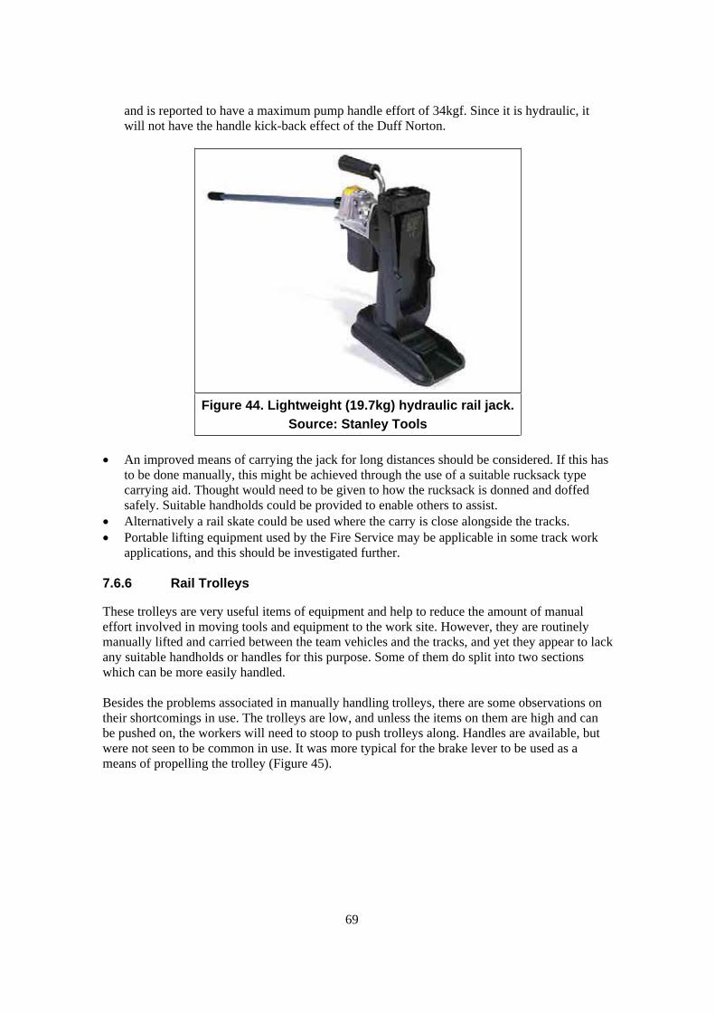
69
and is reported to have a maximum pump handle effort of 34kgf. Since it is hydraulic, it
will not have the handle kick-back effect of the Duff Norton.
Figure 44. Lightweight (19.7kg) hydraulic rail jack.
Source: Stanley Tools
An improved means of carrying the jack for long distances should be considered. If this has
to be done manually, this might be achieved through the use of a suitable rucksack type
carrying aid. Thought would need to be given to how the rucksack is donned and doffed
safely. Suitable handholds could be provided to enable others to assist.
Alternatively a rail skate could be used where the carry is close alongside the tracks.
Portable lifting equipment used by the Fire Service may be applicable in some track work
applications, and this should be investigated further.
7.6.6 Rail Trolleys
These trolleys are very useful items of equipment and help to reduce the amount of manual
effort involved in moving tools and equipment to the work site. However, they are routinely
manually lifted and carried between the team vehicles and the tracks, and yet they appear to lack
any suitable handholds or handles for this purpose. Some of them do split into two sections
which can be more easily handled.
Besides the problems associated in manually handling trolleys, there are some observations on
their shortcomings in use. The trolleys are low, and unless the items on them are high and can
be pushed on, the workers will need to stoop to push trolleys along. Handles are available, but
were not seen to be common in use. It was more typical for the brake lever to be used as a
means of propelling the trolley (Figure 45).
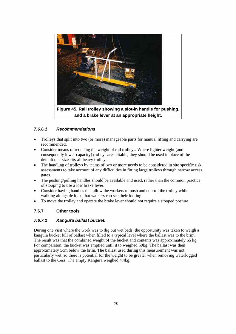
70
Figure 45. Rail trolley showing a slot-in handle for pushing,
and a brake lever at an appropriate height.
7.6.6.1 Recommendations
Trolleys that split into two (or more) manageable parts for manual lifting and carrying are
recommended.
Consider means of reducing the weight of rail trolleys. Where lighter weight (and
consequently lower capacity) trolleys are suitable, they should be used in place of the
default one-size-fits-all heavy trolleys.
The handling of trolleys by teams of two or more needs to be considered in site specific risk
assessments to take account of any difficulties in fitting large trolleys through narrow access
gates.
The pushing/pulling handles should be available and used, rather than the common practice
of stooping to use a low brake lever.
Consider having handles that allow the workers to push and control the trolley while
walking alongside it, so that walkers can see their footing.
To move the trolley and operate the brake lever should not require a stooped posture.
7.6.7 Other tools
7.6.7.1 Kangura ballast bucket.
During one visit where the work was to dig out wet beds, the opportunity was taken to weigh a
kangura bucket full of ballast when filled to a typical level where the ballast was to the brim.
The result was that the combined weight of the bucket and contents was approximately 65 kg.
For comparison, the bucket was emptied until it to weighed 50kg. The ballast was then
approximately 5cm below the brim. The ballast used during this measurement was not
particularly wet, so there is potential for the weight to be greater when removing waterlogged
ballast to the Cess. The empty Kangura weighed 4.4kg.

71
Figure 46. A typical carrying operation when moving ballast
(with 50kg bucket load)
The full buckets would be handled between two workers in any case (Figure 46), but it is
interesting to see how the load could be reduced to a more advisable level for repetitive
handling. A typical shovel load of ballast was weighed as approximately 8kg.
Recommendations
The weight of a Kangura full of ballast should be included in the Carillion Plant List
Weights booklet and be included in manual handling risk assessments. Workers should be
informed of the likely weight when the bucket is full to the brim (including variation
between and materials and conditions) and consideration should be given to training
workers to only partially fill the bucket when the weight exceeds guideline figures.
7.6.7.2 Pan-Puller
An assessment of these tools has not been made, but they were reportedly unreliable in
operation, and associated with an increase in slip and trip risk. The wide variety of clips that are
encountered may compromise the effectiveness of the tool. The keying hammer was reported to
be the preferred option in some situations. Indeed we observed hammers being used on several
site visits.
Recommendation
The use of these tools is considered to warrant investigation in terms of MSD and general
health and safety risks.
7.6.7.3 Generators
The handling of generators has not been considered in detail in this project, but it is clear that
the manual handling of generator used in track maintenance work can be a relatively high risk
operation. It is also clear that there are a number of improvements that can be made to their
design to aid handling:
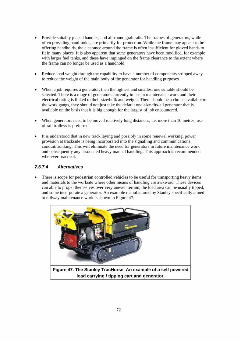
72
Provide suitably placed handles, and all-round grab rails. The frames of generators, while
often providing hand-holds, are primarily for protection. While the frame may appear to be
offering handholds, the clearance around the frame is often insufficient for gloved hands to
fit in many places. It is also apparent that some generators have been modified, for example
with larger fuel tanks, and these have impinged on the frame clearance to the extent where
the frame can no longer be used as a handhold.
Reduce load weight through the capability to have a number of components stripped away
to reduce the weight of the main body of the generator for handling purposes.
When a job requires a generator, then the lightest and smallest one suitable should be
selected. There is a range of generators currently in use in maintenance work and their
electrical rating is linked to their size/bulk and weight. There should be a choice available to
the work gangs, they should not just take the default one-size-fits-all generator that is
available on the basis that it is big enough for the largest of job encountered.
When generators need to be moved relatively long distances, i.e. more than 10 metres, use
of rail trolleys is preferred
It is understood that in new track laying and possibly in some renewal working, power
provision at trackside is being incorporated into the signalling and communications
conduit/trunking. This will eliminate the need for generators in future maintenance work
and consequently any associated heavy manual handling. This approach is recommended
wherever practical.
7.6.7.4 Alternatives
There is scope for pedestrian controlled vehicles to be useful for transporting heavy items
and materials to the worksite where other means of handling are awkward. These devices
can able to propel themselves over very uneven terrain, the load area can be usually tipped,
and some incorporate a generator. An example manufactured by Stanley specifically aimed
at railway maintenance work is shown in Figure 47.
Figure 47. The Stanley TracHorse. An example of a self powered
load carrying / tipping cart and generator.
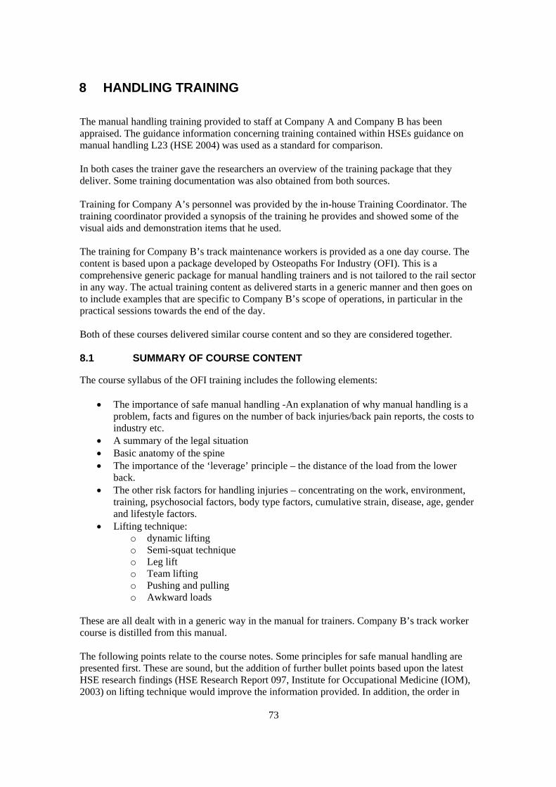
73
8 HANDLING TRAINING
The manual handling training provided to staff at Company A and Company B has been
appraised. The guidance information concerning training contained within HSEs guidance on
manual handling L23 (HSE 2004) was used as a standard for comparison.
In both cases the trainer gave the researchers an overview of the training package that they
deliver. Some training documentation was also obtained from both sources.
Training for Company A’s personnel was provided by the in-house Training Coordinator. The
training coordinator provided a synopsis of the training he provides and showed some of the
visual aids and demonstration items that he used.
The training for Company B’s track maintenance workers is provided as a one day course. The
content is based upon a package developed by Osteopaths For Industry (OFI). This is a
comprehensive generic package for manual handling trainers and is not tailored to the rail sector
in any way. The actual training content as delivered starts in a generic manner and then goes on
to include examples that are specific to Company B’s scope of operations, in particular in the
practical sessions towards the end of the day.
Both of these courses delivered similar course content and so they are considered together.
8.1 SUMMARY OF COURSE CONTENT
The course syllabus of the OFI training includes the following elements:
The importance of safe manual handling -An explanation of why manual handling is a
problem, facts and figures on the number of back injuries/back pain reports, the costs to
industry etc.
A summary of the legal situation
Basic anatomy of the spine
The importance of the ‘leverage’ principle – the distance of the load from the lower
back.
The other risk factors for handling injuries – concentrating on the work, environment,
training, psychosocial factors, body type factors, cumulative strain, disease, age, gender
and lifestyle factors.
Lifting technique:
o dynamic lifting
o Semi-squat technique
o Leg lift
o Team lifting
o Pushing and pulling
o Awkward loads
These are all dealt with in a generic way in the manual for trainers. Company B’s track worker
course is distilled from this manual.
The following points relate to the course notes. Some principles for safe manual handling are
presented first. These are sound, but the addition of further bullet points based upon the latest
HSE research findings (HSE Research Report 097, Institute for Occupational Medicine (IOM),
2003) on lifting technique would improve the information provided. In addition, the order in
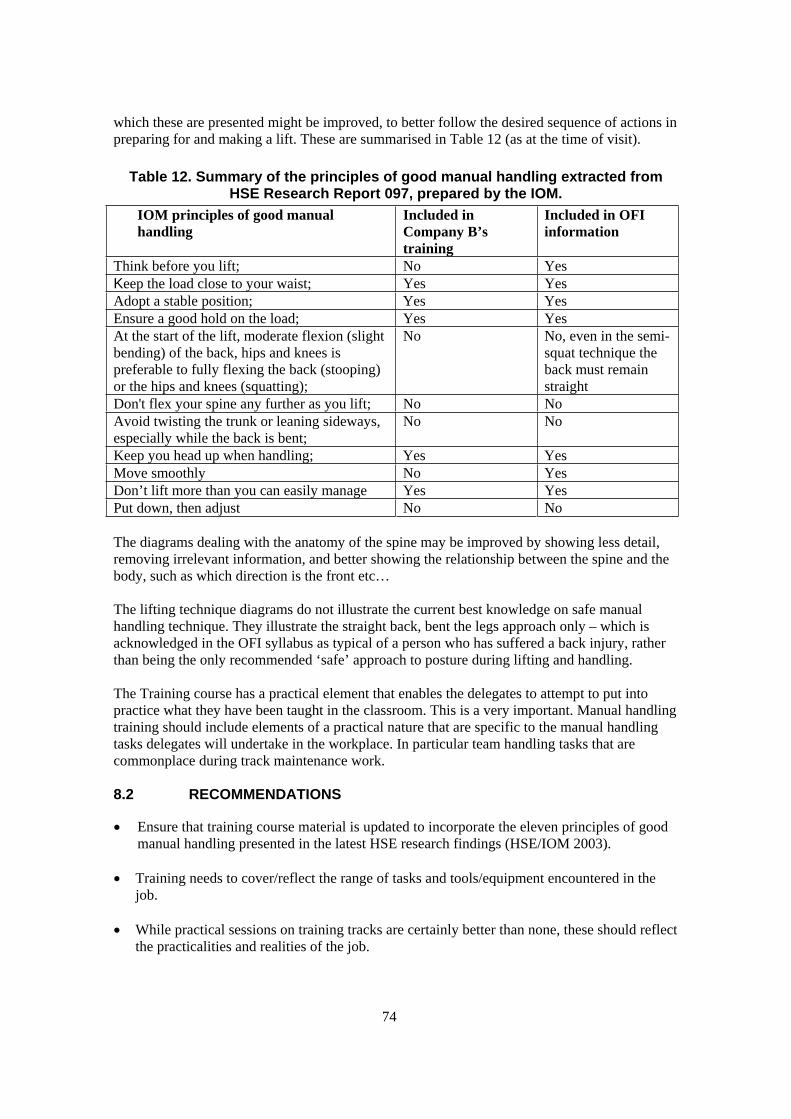
74
which these are presented might be improved, to better follow the desired sequence of actions in
preparing for and making a lift. These are summarised in Table 12 (as at the time of visit).
Table 12. Summary of the principles of good manual handling extracted from HSE Research Report 097, prepared by the IOM.
IOM principles of good manual
handling
Included in
Company B’s
training
Included in OFI
information
Think before you lift; No Yes
Keep the load close to your waist; Yes Yes
Adopt a stable position; Yes Yes
Ensure a good hold on the load; Yes Yes
At the start of the lift, moderate flexion (slight
bending) of the back, hips and knees is
preferable to fully flexing the back (stooping)
or the hips and knees (squatting);
No No, even in the semi-
squat technique the
back must remain
straight
Don't flex your spine any further as you lift; No No
Avoid twisting the trunk or leaning sideways,
especially while the back is bent;
No No
Keep you head up when handling; Yes Yes
Move smoothly No Yes
Don’t lift more than you can easily manage Yes Yes
Put down, then adjust No No
The diagrams dealing with the anatomy of the spine may be improved by showing less detail,
removing irrelevant information, and better showing the relationship between the spine and the
body, such as which direction is the front etc…
The lifting technique diagrams do not illustrate the current best knowledge on safe manual
handling technique. They illustrate the straight back, bent the legs approach only – which is
acknowledged in the OFI syllabus as typical of a person who has suffered a back injury, rather
than being the only recommended ‘safe’ approach to posture during lifting and handling.
The Training course has a practical element that enables the delegates to attempt to put into
practice what they have been taught in the classroom. This is a very important. Manual handling
training should include elements of a practical nature that are specific to the manual handling
tasks delegates will undertake in the workplace. In particular team handling tasks that are
commonplace during track maintenance work.
8.2 RECOMMENDATIONS
Ensure that training course material is updated to incorporate the eleven principles of good
manual handling presented in the latest HSE research findings (HSE/IOM 2003).
Training needs to cover/reflect the range of tasks and tools/equipment encountered in the
job.
While practical sessions on training tracks are certainly better than none, these should reflect
the practicalities and realities of the job.
75
In demanding manual handling jobs like track maintenance work, it is important that new
team members are properly inducted into the work team and given on-the-job supervision.
Efforts need to be made to ensure that training is based in reality and closely reflects what is
carried out in practice by the work teams. Training is rendered irrelevant if newly trained
staff go to work and pick up or revert to bad habits. Manual handling methods should
therefore be integrated with the technical training given to trackside workers. Trainers need
to have an in-depth understanding of working practices and methods and should develop
training packages in conjunction with experienced staff members.
Supervisors, team leaders, and engineers should all be kept up to date with the current
manual handling methods associated with track maintenance work, and options for avoiding
or reducing manual handling.
To ensure work teams are using the most appropriate methods (i.e. those recommended in
training), supervisory checks and monitoring should be undertaken periodically. This is
most important in activities known to be especially associated with injuries. Therefore it
should be linked with accident and ill health monitoring.
76
9 OVERALL SUMMARY OF FINDINGS
This project’s principal objectives were to identify the major causes of manual handling and
other MSDs in the rail sector track, depot and platform work activities, and to present effective
and practical control measures.
From the sickness and absence data it is clear that track maintenance operations are the category
of rail sector work most associated with manual handling related accidents and musculoskeletal
ill health.
After considering the evidence from the sickness and absence data, the literature review, and in
the light of observations of a range of work activities and discussions with maintenance
contractors, health and safety personnel and operational staff, the scope was narrowed to focus
on track maintenance work, and in particular on a limited set of track maintenance operations
most associated with musculoskeletal ill health. These were:
Coupling operations in shunting yards;
Lever operation tasks in shunting yards, depots and signal boxes;
Sleeper replacement, both wooden and concrete;
Unloading/loading of tools and equipment associated with maintenance work;
Use of selected commonly used tools and equipment in maintenance operations.
Our own application of the HSENMQ prevalence question set on a sample of track maintenance
workers suggests that the prevalence of musculoskeletal symptoms amongst this work group is
higher for low back and ankle/foot injuries than other comparable worker groups.
Despite the apparent widespread nature of MSD ill health amongst track maintenance workers
there is relatively little scientific literature in the public domain dealing with the practicalities of
the subject. Those studies that have been undertaken are spread worldwide and deal with a
variety of railway work operations. However, these do concur with our own findings regarding
prevalence of musculoskeletal ill health in sickness and absence data and in terms of the
physical risk factors found to be present in the work operations.
Of track maintenance operations, the following have been identified as presenting a high risk of
MSD injury and ill health:
Coupling operations in shunting yards using the coupling pole
Lever operation tasks at trackside and in Signal Boxes where lever operating force
exceeds 40kgf.
The manual lifting carrying and some dragging of sleepers during replacement, both
wooden and concrete;
The unloading/loading of certain tools and equipment associated with maintenance
work;
Manual handling aspects of the use of the following tools and equipment:
o Rail profile grinders such as the Geismar MP12.
o Rail disc cutters
o Rail jacks such as the Duff Norton Rail Jack
o Kangura ballast bucket lifting when fully loaded with ballast
o Manual movement of certain train jacks in maintenance depots.
o Certain lifts of Thermite welding equipment
77
Practical recommendations are made for means of reducing the risks to musculoskeletal ill
health in the above (and other) tasks. These are presented within the relevant sections and are
also collated and summarised in Section 10.
9.1 OTHER OBSERVATIONS
9.1.1 Design of tools and equipment
Many items of equipment that are intended to assist with manual handling are considered to be
of a relatively unrefined nature. A prime example are the variety of lifting tongs for sleepers and
rail. They are constructed of heavy-duty material to simple designs, since this is appropriate for
the typical circumstances of use (see below), but there is typically no refinement in the design
reflecting more than a passing consideration for the users. Handle sizes and dimensions appear
to be arrived at by chance, handle dimensions are typically small, and smooth. The same can be
said to varying degrees for the wider range of tools and equipment.
9.1.2 Treatment of tools and equipment
It has been noted that it is typical for almost all tools and equipment used on site in track
maintenance work to be treated with little care. Tools such as sledgehammers, keying hammers,
pick axes, spanners, pan-pullers etc, etc, are routinely thrown aside when they are no longer
required. Besides the obvious wear and tear issues, this means that when the tools are to be used
again, they have to be picked up from ground level. The weights of some of these tools are
significant. Understandably the worker’s attention will be focused on getting the job done, and
it is unlikely that any worker will think of this as a manual handling operation, and consequently
will pay little attention to their posture when reaching for the tool. This practice is considered to
significantly add to the workload on workers, and consequently the overall risk of
musculoskeletal injury.
9.1.3 Compulsory wearing of safety helmets
At all of Company B’s work sites that were visited, hard hats were required to be worn. This is a
universal requirement for all track maintenance work for Company B. It is not based upon a
local risk assessment. While the rationale behind this decision is understood, during the track
maintenance work activities that we observed, wearing a hard hat caused problems for the
majority of the workers. The work performed typically requires bending and stooping, and is
hard physically, therefore excess body heat is generated. Wearing a hard hat then becomes both
difficult due to the bending, and uncomfortable due to sweating. It is therefore also
understandable why track maintenance workers would prefer not to wear their helmets during
this kind of work where there is little risk of head injury. This safety rule is likely to fall in
disrepute as workers ignore it and supervisors ‘turn a blind eye’.
9.1.4 Means of avoiding carrying of tools and equipment onto remote worksites
The need for workers to transport heavy and awkward tools and equipment onto remote work
sites is a significant contributor to worker’s overall exposure to manual handling risk factors.
Also, the increasing difficulty of gaining access to the track through the closure of access points
was highlighted to use during discussions with the work teams.
There would appear to be options to reduce or avoid some or all of the repeated loading and
unloading, lifting carrying and pushing through the use of tool and equipment containers which

78
can be dropped off by rail vehicle when delivering materials such as sleepers or ballast etc..
These types of secure and robust tool storage are used in the construction industry. Indeed, some
construction companies use adapted International Shipping Containers as site offices as well as
secure tool storage. This links with another observation, which is the dereliction of Trackside
huts in remote areas. As well as providing storage these huts used to provide basic welfare
facilities. There may be some benefits in reviewing that model of basic tool and welfare
provision in certain areas.
As well as reducing the musculoskeletal load, avoiding or reducing the manual movement of
tools along the track would also reduce the risk of slip trip and fall accidents. Likewise
improvements in terms of reducing slips, trips and fall accidents are likely to reduce the risk
associated with manual handling activities.
79
10 SUMMARY OF RECOMMENDATIONS
The following summarises the recommendations developed throughout this project for means of
reducing the risks of musculoskeletal injury in the rail sector, and in track maintenance work in
particular. These will be relevant to HMRI Inspectors and rail industry health and safety
practitioners.
10.1 PAN JACK CARRYING OPERATION
When carrying with the weight on one shoulder, such as pan-jacks, it is considered
worthwhile considering the following measures to improve the comfort of the carry
operation, and reduce the risk of injury from localised pressure:
Provide firm padding in the work wear. This could include the hi-visibility vests, insulated
vests and jackets. It might be advisable for the padding to be removable.
Provide detachable shoulder straps to support/carry
Provide suitable rucksack type carrying aids.
10.2 SHOVELS
Suitable shovels in terms of design, handle length, and weight. A range of sizes to enable
larger and smaller workers to use a tool that best suits them will assist in enabling workers
to adopt less fatiguing postures.
Consider how impact type vibration and shock might be reduced through handle materials
and design
10.3 DEPOT TRAIN JACKS
Mechanical/powered assistance should be provided for moving these types of train jacks.
If they have to be moved manually, should not require excessive force, i.e. should be
comfortably moveable by a single worker, exerting forces within the push/pull force
guidelines presented in L23 of 20kgf initial and 10kgf sustained for males, and 15 and 7kg
respectively for females. Appropriate handholds etc, should be provided for this purpose.
10.4 DMU CLEANING:
Walkway access level with the train interior
Maintain job rotation – make sure it is formally operated
10.5 DMU REPLENISHING TASKS:
Use a hook shaped rigid end to the water tank filling pipe. This would reduce the need to
reach so awkwardly, and eliminated the need for the workers to bend the end of the hose
over. Female workers should be able to perform this operation without difficulty or risk.
A shaped hose end would assist here too, or perhaps some other means of avoiding the need
to stoop so severely. To further reduce the manual load on the workers, a powered pump
rather than a manual one may be of benefit (the pumping operation was not observed).
10.6 DMU CAB WINDOW/CARRIAGE END WASHING:
Address the potential for falls into the pit.
80
Use a platform to get up closer to the windows – This will improve working postures, avoid
the need for long handled tools and reduce the forces exerted during the operation. A
platform is available at the site and is used for other maintenance operations (Figure 52). A
platform like this would appear to be suitable for the cab window cleaning operation.
Alternatively, use proprietary pole window cleaning equipment with integral water supply,
and or a pressure washer.
10.7 THERMITE WELDING
Welders in track maintenance work may be exposed to significant musculoskeletal risks, for
example handling of gas cylinders, and other heavy equipment. Although a specialist
operation probably with a small population of workers, it is therefore recommended that the
MSD risks associated with welding operations should be looked at in more detail.
10.8 COUPLING OPERATIONS
Hand lifting method - If the lift can be performed more symmetrically and with less twist,
the risk may be reduced further. This should be investigated more formally and if successful
included in training programmes.
Pole leverage method - This approach is not recommended as a risk control option in place
of the hand lifting method above.
Pole lift method - This method is not recommended.
Situations where coupling and/or uncoupling operations are performed intensively should
be the subject of special risk assessments, and control measures investigated.
10.9 LEVER OPERATIONS
Lever operation tasks should be the subject of detailed manual handling/push-pull risk
assessments;
Compatibility issues should be closely scrutinised in order to minimise the risks to
Signallers.
Lever operating forces should be reduced wherever possible, this may be achieved through
improved maintenance, and an investigation of the potential benefits of this is
recommended;
Levers requiring notably high operating forces (say twice the L23 filter figure, i.e. 40kgf)
should be identified as such, and one means of dealing with them may be to employ a 2-
person operation where practicable;
Ensure that the underfoot conditions at levers sites are good, and high friction.
10.10 SLEEPER REPLACEMENT
Avoid, where practicable, the manual lifting of heavy sleepers. There are a wide range of
machines (such as the Geismar MRT, and the Harsco Track Technologies sleeper handlers)
that can replace all types of sleepers mechanically. The whole of the sleeper handling and
movement is achieved mechanically.
For dual line working, it would seem possible for the sleeper to be moved mechanically by
a road/rail excavator. There are specialised attachments available, however it seems likely
that an excavator could be used with slings or other common lifting equipment.
For single line working, the possibility of using a road rail excavator should be investigated,
as there may be practical difficulties. However, if an excavator is being used at the site it
could at least be used (before the rails are jacked) to position the replacement sleepers ready

81
for manual movement into final position. This could mean that only a single manual drag
would be necessary.
Investigate the possibility of using a portable powered or even manual winch to pull the
sleepers from the Cess and under the raised rails. In dual line working this might be attached
to the adjacent line in some way (so long as this does not cause damage). Alternatively there
may be some suitable means of anchoring. If the sleepers were accurately located during
delivery this could avoid the need for any manual lifting or dragging.
Generic risk assessments for manual handling operations such as team sleeper handling
must be supplemented with site specific assessments, as the local working conditions have a
large effect on the level of risk involved.
Ensure that the sleepers are dropped off at exactly the point of use. Changes may be needed
in the that sleepers requiring replacement are marked so that the operator of the delivery
vehicle can identify location accurately. This could reduce the amount of manual handling
associated with each sleeper considerably. The orientation of the sleepers is also important.
They should always be the correct way up.
Ensure that sufficient ballast is dug away to enable the old and new sleepers to be moved as
easily as possible.
Ensure that the necessary numbers of personnel are available as indicated in the risk
assessment, and that they follow the prescribed system of work.
The practice of dragging in place of lifting appears should be encouraged. On the basis of
observations the practice of moving the sleepers longer distances manually along the rails
by dragging is preferable to a lift and carry in terms of minimising the risk of
musculoskeletal injury.
Undertake an appraisal of the design of the sleeper handling tool – see below.
10.10.1 Recommendation specific to the continued manual handling of wooden sleepers in replacement work
10.10.1.1 The two-man pull out of old sleepers
Consider the use of mechanical aids to pull the sleeper out from under the rails, e.g. a
winch.
Make this a four person operation, as per the insertion method.
Provide sleeper nips with handles large enough to enable both hands to be used.
Plan the organisation of the work to avoid creating obstacles to the later process, i.e. avoid
dragging sleepers out and into a ditch.
10.10.1.2 Two-man lift of old sleepers to the rail trolley
The practice of throwing the sleepers across in front of the body should be avoided when
transferring the old sleepers between the track and the trolley. If the trolley is moved close
to the next sleeper after each is lifted, a controlled lift and place operation can be performed.
10.11 SLEEPER LIFTING TOOLS
The design of the tools should be critically reviewed with the aim of making improvements:
The characteristics of the tools should more closely match the requirements of the
workforce in terms of its suitability for lifting and dragging operations, its size to enable
optimal lifting posture, handle dimensions, etc…
A means of enabling workers lift and carry without being in such close proximity;
The relative advantages and disadvantages to workers of lifting in the two possible
orientations should be investigated;
82
The tools should locate positively in the sleeper, and be able to withstand uneven loading
without disengaging;
10.12 EQUIPMENT UNLOADING AND LOADING
The unit weight of many of the generic ‘packages’ of items loaded and unloaded should be
established, listed and marked on them.
Consider using smaller unit packages, such as smaller drums and bins to control the
maximum weights handled at any one time.
Consider using smaller gas cylinders that can be more easily handled.
Provide greater uniformity of containers and packages, including uniformity in terms of the
handles provided, their design, location and number, appropriate to the number of persons
required to lift and handle in relative safety.
10.13 RAIL GRINDERS
Undertake a detailed assessment of the risks involved in this work activity, including
quantification of the forces involved.
In the short-term the use of the outrigger to support the tool in operation is recommended.
Review the design of the grinders available to reduce the amount and duration of forward
trunk flexion required, reduce the forces applied and to make the grinder lighter and easier
to lift and carry. There are equivalent grinders available that avoid the need to bend over
and support the device to such an extent, and these may present a significantly lower risk.
For example the Stanley PG10 has a mechanism whereby the operator remains stood
upright throughout the grinding operation Figure 33. It is also powered by compressed air
reducing the weight to 53kg.
Rotate workers between this operation and other tasks where there is an opportunity for
recovery, i.e. tasks not involving severe forward trunk flexion. Rotation between workers
during the operation should also be considered.
10.14 NUT RUNNERS
Using this tool in a horizontal orientation to tighten fishplate bolts is not recommended.
Even if the tool can be supported on the ground, this would still present a high risk of
injury due to the postural issues. There is also the consideration of the handling activity
associated with moving the tool from one point of use to the next. The operation will
involve handling a 20kg load at between knee and ground level.
Angled and long handled nut runners are available for applications such as fishplate bolt
work and can avoid the need for the operator to stoop (Figure 36).
As there appears to be tendency for worker to stoop during use, the tool may be
improved with the addition of handles that would enable workers to avoid stooping.
There was not sufficient opportunity within this study to make a more detailed appraisal
of the design.
A shoulder strap may assists in carrying the tool, but when it is being used intensively
or moved over long distances a rail scooter or trolley may be more appropriate.
Simple long handled spanners or wrenches may be more appropriate for tasks like fish
plate tightening. They are lighter in weight, do not vibrate, are quiet, and allow an
upright posture.
The decision regarding what tools to use on a job is made at a local level and it is
important that safety and health issues are balanced with productivity. It is therefore
important that the team leaders have the appropriate knowledge to make such decisions,
and this should be provided in both technical and manual handling training.
83
10.15 DISC CUTTERS
Lighter weight and improved designs should be sought.
Address the postural issues, and allow the worker full use of the tool in a standing position
through the provision long handled cutters (Figure 38). The cutter shown is also
pneumatically powered, so the device is considerably lighter (24.5kg) than a petrol powered
version.
10.16 SLEEPER AND RAIL LIFTING NIPS
There is scope for a comprehensive review of the design of these lifting tools to improve
usability through incorporating ergonomics principles with the aim of optimising lifting and
carrying postures, and spacing and orientation of workers in teams for the range of tasks for
which they are used, including lifting, carrying and dragging.
10.17 DUFF NORTON RAIL JACK
The risk of injury from the handle springing back can be avoided through the use of
hydraulic operation.
Reduce the weight of the tool to within guideline figures for lifting and carrying. A weight
of 20kg or less would constitute a significant reduction in risk.
Investigate alternative tools and handle design options, for example see Figure 44. Although
the carry handle may not be ideal, it is a significant improvement on the short, curved and
sculpted Duff Norton handle. The example pictured has a 10 tonne capacity, weighs 19.7kg
and is reported to have a maximum pump handle effort of 34kgf. Since it is hydraulic, it
will not have the handle kick-back effect of the Duff Norton.
An improved means of carrying the jack for long distances should be considered. If this has
to be done manually, this might be achieved through the use of a suitable rucksack type
carrying aid. Thought would need to be given to how the rucksack is donned and doffed
safely. Suitable handholds could be provided to enable others to assist.
Alternatively a rail skate could be used where the carry is close alongside the tracks.
10.18 KANGURA BALLAST BUCKET
The weight of a Kangura full of ballast should be included in the Carillion Plant List
Weights booklet and be included in manual handling risk assessments.
In training workers should be informed of the likely weight when the bucket is full to the
brim (including variation between and materials and conditions).
Consideration should be given to training workers to only partially fill the bucket when the
weight is likely to exceed guideline figures for one or two person lifts.
10.19 PAN-PULLER
Due to reports of ineffectiveness, MSD, and slip risks, the use of these tools is considered to
warrant investigation in terms of both MSD and general health and safety risks.
10.20 GENERATORS
Provide suitably placed handles, and all-round grab rails.
Where generators are modified, for example with larger fuel tanks, consider the
consequences for manual handling and ensure that these do not compromise clearance at
handholds.
84
Consider the use of generators with the capability to have a number of components stripped
away to reduce the weight of the main body of the generator for handling purposes.
The most appropriate capacity and size of generator for the job should be used. If a job
requires a generator, then the lightest and smallest one suitable should be selected. There
should be a choice available to the work gang, they should not just take the default/standard
generator that is available on the basis that it is big enough for the largest of job
encountered.
When generators need to be moved relatively long distances, i.e. more than 10 metres, use
of rail trolleys is preferred.
There appears to be scope for pedestrian controlled vehicles to be used for transporting
heavy items and materials to the worksite where other means of handling are awkward.
These devices are able to propel themselves over very rough terrain. The load area can
usually be tipped. Some also incorporate a generator.
It is understood that in new track laying and possibly in some renewal working, power
provision at trackside is being incorporated into the signalling and communications
conduit/trunking. This will eliminate the need for generators in future maintenance work
and consequently any associated heavy manual handling. This approach is recommended
wherever practical.
10.21 MSD SURVEY
Based upon our application of the HSEMSSQ prevalence question set in this project, the
following recommendations are made:
The HSEMSSQ in abbreviated or full form is considered to be of potential benefit as an
active musculoskeletal health monitoring tool;
It should be applied anonymously;
It should be applied by an interviewer rather than by self completion;
For active monitoring purposes it should be repeated every 1 to 2 years;
A section for identifying contributory work activities would be a useful addition.
Consider including the section for identifying psychosocial factors.
10.22 TRAINING
Ensure that training course material is updated to incorporate the eleven principles of good
manual handling presented in the latest HSE research findings (Research Report 097, 2003).
In demanding MH jobs like track maintenance work, it is important that new team members
are properly inducted into the work team and given on-the-job supervision. Efforts need to
be made to ensure that training is based in reality and closely reflects what is carried out in
practice by the work teams. Manual handling methods should therefore be integrated with
the technical training given to trackside workers.
Trainers need to have an in-depth understanding of working practices and methods and
should develop training packages in conjunction with experienced staff members.
Supervisors, team leaders, and engineers should all be kept up to date with the current
manual handling methods associated with track maintenance work, and options for avoiding
or reducing manual handling.
To ensure work teams are using the most appropriate methods (i.e. those recommended in
training), supervisory checks and monitoring should be undertaken periodically. This is
most important in activities known to be especially associated with injuries. Therefore it
should be linked with accident and ill health monitoring.

85
11 RECOMMENDATIONS FOR FURTHER WORK
This project has identified a number of high-risk manual handling operations. There is clearly a
great deal of scope to expand on this work to look more closely at those activities and the tools
and equipment that it was not possible to include in the this study. From our observations the
following areas of work activity are suggested:
Train cleaning, interior and exterior;
Rolling stock maintenance work;
Track maintenance activities not covered in this project;
Renewal and new track laying work;
Station operations involving manual handling (such as luggage handling, any handling
associated with assisting less able bodied passengers, etc.);
On-train operations involving heavy handling (such as catering trolleys).
Arising from this study, the following recommendations for specific project work are made:
The quantification of the loads placed on individual team members during team lifting,
carrying and dragging of sleepers. These have been assessed as high risk operations without
direct quantification. The dynamics of the operation may mean that the loads placed on
individuals exceed those that have been assumed from the mass of the load alone. This is
especially likely to be the case when something goes wrong, such as a team member
slipping, or a lifting tool loosing grip, as was seen during site visits. To definitively
establish the degree of risk to individuals in these situations quantification is necessary,
although this is likely to be difficult technically.
Dragging of sleepers is a practice that is currently used as a lower risk alternative to lifting
and carrying and is recommended as an alternative in this report (given that the overall force
required to drag a sleeper appears to be reduced compared with lifting and carrying). It may
be that this approach can be adopted more widely as a means of reducing risks, however, it
is not without risk, and further work is required to better understand the risks and establish
the number of personnel required to make a drag in relative safety. This might be most
easily achieved by using instrumentation during a mechanical dragging operation to
simulate the conditions of moving a sleeper though ballast, and on the rails. This would
inform the development of suitable tools and systems of work. The practice will also need
to be addressed in training and this process would also inform the training requirements.
Undertake ergonomics evaluations of tools and equipment included in the Company B
Plant List Weights booklet, but not covered in this report. For example:
o Rail drilling equipment
o Stressing equipment
o Lighting kit
o Further lifting equipment
o Ballast tamping equipment
o Spike applicators and removers
o Warning and safety equipment
o Huck bolt equipment
o Welding and brazing equipment
o Further grinding and cutting equipment
o Pumps
o Cold expansion equipment
o Pan-pullers

86
Undertake an ergonomics based appraisal of the potential for using equipment and
techniques employed in other industry sectors.
Make an ergonomics appraisal of any additional manual handling implications created when
handling tools and equipment for track maintenance work in Third Rail electrified areas.

87
12 APPENDICES
12.1 APPENDIX 1 - FORCE MEASUREMENTS TAKEN AT A SHUNTING YARD
Instanter coupling
17.4
17.0
15.4
17.1
Mean = 16.73
Screw coupling #1
16.8
23.9
19.7
23.4
22.4
24.2
24.2
Mean = 22.09
Screw coupling #2 (continental type)
28.4
27.9
29.2
28.4
Mean = 28.48
Screw coupling #3 (continental type)
27.3
29.3
29.0
33.0
Mean = 29.65
Points levers 1. Standard lever
44.6 60.9
40.3 63.0
- 59.8
Mean = 42.45!Syntax Error, ) = 61.3
2. Bullhead rail, short point 3-5 metres
42.0 43.0
40.7 41.0
42.2 46.3
41.63 -
Mean = 41.85 43.3
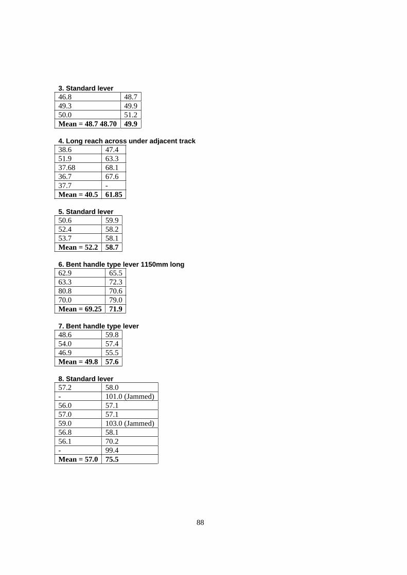
88
3. Standard lever
46.8 48.7
49.3 49.9
50.0 51.2
Mean = 48.7 48.70 49.9
4. Long reach across under adjacent track
38.6 47.4
51.9 63.3
37.68 68.1
36.7 67.6
37.7 -
Mean = 40.5 61.85
5. Standard lever
50.6 59.9
52.4 58.2
53.7 58.1
Mean = 52.2 58.7
6. Bent handle type lever 1150mm long
62.9 65.5
63.3 72.3
80.8 70.6
70.0 79.0
Mean = 69.25 71.9
7. Bent handle type lever
48.6 59.8
54.0 57.4
46.9 55.5
Mean = 49.8 57.6
8. Standard lever
57.2 58.0
- 101.0 (Jammed)
56.0 57.1
57.0 57.1
59.0 103.0 (Jammed)
56.8 58.1
56.1 70.2
- 99.4
Mean = 57.0 75.5
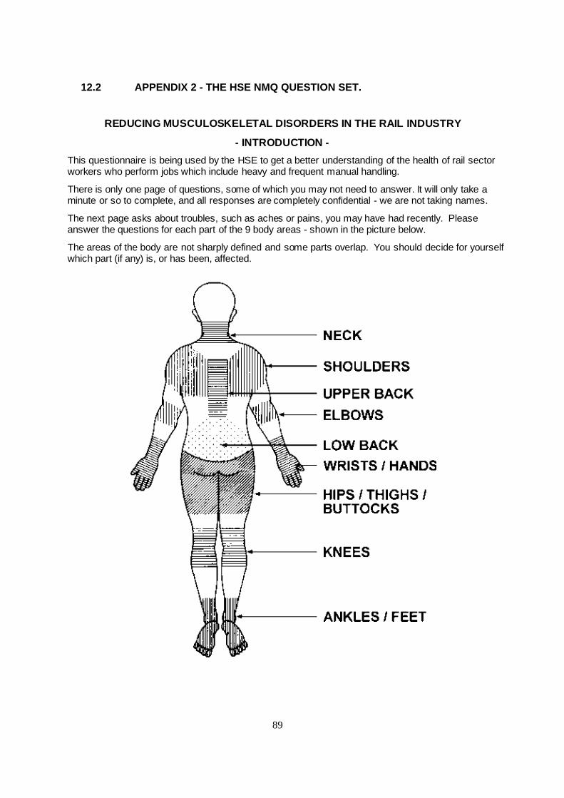
89
12.2 APPENDIX 2 - THE HSE NMQ QUESTION SET.
REDUCING MUSCULOSKELETAL DISORDERS IN THE RAIL INDUSTRY
- INTRODUCTION -
This questionnaire is being used by the HSE to get a better understanding of the health of rail sectorworkers who perform jobs which include heavy and frequent manual handling.
There is only one page of questions, some of which you may not need to answer. It will only take aminute or so to complete, and all responses are completely confidential - we are not taking names.
The next page asks about troubles, such as aches or pains, you may have had recently. Pleaseanswer the questions for each part of the 9 body areas - shown in the picture below.
The areas of the body are not sharply defined and some parts overlap. You should decide for yourselfwhich part (if any) is, or has been, affected.

90
Have you at any time during the last three months had trouble (such as ache, pain, discomfort, numbness, tingling, or pins and needles) in your:
Have you had this troubleduring the last seven days?
During the last three months has this trouble prevented you carrying out normal activities (e.g., job, housework, hobbies)?
1. Neck a) No Yes
1� 2�b) No Yes
1� 2�c) No Yes
1� 2�2. Shoulders a) No Yes
1� 2�in both or either
b) No Yes
1� 2� in both or either
c) No Yes
1� 2� in both or either
3. Elbows a) No Yes
1� 2� in both or either
b)No Yes
1� 2� in both or either
c) No Yes
1� 2� in both or either
4. Wrists/ hands a) No Yes
1� 2� in both or either
b) No Yes
1� 2� in both or either
c) No Yes
1� 2� in both or either
5. Upper back a) No Yes
1� 2�b) No Yes
1� 2�c) No Yes
1� 2�6. Lower back (small of back)
a) No Yes
1� 2�b) No Yes
1� 2�c) No Yes
1� 2�7. Hips/ thighs/ buttocks a) No Yes
1� 2� in both or either
b) No Yes
1� 2� in both or either
c) No Yes
1� 2� in both or either
8. Knees a) No Yes
1� 2� in both or either
b) No Yes
1� 2� in both or either
c) No Yes
1� 2� in both or either
9. Ankles/ feet a) No Yes
1� 2� in both or either
b) No Yes
1� 2� in both or either
c) No Yes
1� 2� in both or either
- Thank you -
Please check you have answered ALL of the questions on this page.
Reference number:
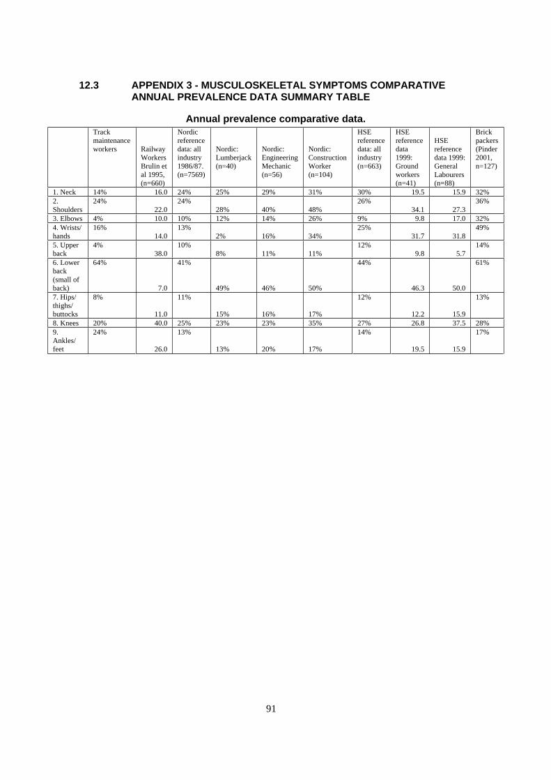
91
12.3 APPENDIX 3 - MUSCULOSKELETAL SYMPTOMS COMPARATIVE ANNUAL PREVALENCE DATA SUMMARY TABLE
Annual prevalence comparative data.
Track
maintenance
workers Railway
Workers
Brulin et
al 1995,
(n=660)
Nordic
reference
data: all
industry
1986/87.
(n=7569)
Nordic:
Lumberjack
(n=40)
Nordic:
Engineering
Mechanic
(n=56)
Nordic:
Construction
Worker
(n=104)
HSE
reference
data: all
industry
(n=663)
HSE
reference
data
1999:
Ground
workers
(n=41)
HSE
reference
data 1999:
General
Labourers
(n=88)
Brick
packers
(Pinder
2001,
n=127)
1. Neck 14% 16.0 24% 25% 29% 31% 30% 19.5 15.9 32%
2.
Shoulders
24%
22.0
24%
28% 40% 48%
26%
34.1 27.3
36%
3. Elbows 4% 10.0 10% 12% 14% 26% 9% 9.8 17.0 32%
4. Wrists/
hands
16%
14.0
13%
2% 16% 34%
25%
31.7 31.8
49%
5. Upper
back
4%
38.0
10%
8% 11% 11%
12%
9.8 5.7
14%
6. Lower
back
(small of
back)
64%
7.0
41%
49% 46% 50%
44%
46.3 50.0
61%
7. Hips/
thighs/
buttocks
8%
11.0
11%
15% 16% 17%
12%
12.2 15.9
13%
8. Knees 20% 40.0 25% 23% 23% 35% 27% 26.8 37.5 28%
9.
Ankles/
feet
24%
26.0
13%
13% 20% 17%
14%
19.5 15.9
17%

92
13 REFERENCES
3D Static Strength Prediction Program v4.0. The University of Michigan, Centre for
Ergonomics, 1997.
Amell T.K, Kumar S. (2001) Industrial hand wheel actuation and the human operator: A review.
International Journal of Industrial Ergonomics 28. pp 291-302
Boocock, M. (1997) Team Handling: Updated Literature Review, HSE Internal Report
(EWP/97/13).
Borg, G., Ottoson, D. (1985) Perception of Exertion in Physical Work. Proceedings of an
International Symposium, Stockholm, 3-5 October 1985, MacMillan, London.
Brulin C., Jonsson B., Karlehagen, S. (1985) Musculoskeletal problems in railway station
personnel – a descriptive epidemiological study.
BS EN 1005-2:2002 Safety of Machinery – Human physical performance – Part 2: Manual
handling of machinery and component parts of machinery.
BS EN 1005-3:2002 Safety of Machinery – Human physical performance – Part 3:
Recommended force limits for machinery operation.
Company B (undated) Plant list weights. Staff booklet.
Company B (undated) Weights of common plain line permanent way materials. Staff booklet.
Chaffin, D.B. and Park. K.S. (1973) A longitudinal study of low-back pain as associated with
occupational weight lifting factors. AIHAJ, 32 513-525.
Chaffin, D.B and Anderson, G.B.J. 1984, Occupational Biomechanics (John Wiley & Sons,
New York).
Dennis C.J., Barrett R. S. (2002) Spinal loads during individual and team lifting. Ergonomics
Vol. 45, No. 10, August 2002.
Dickinson, C.E, Campion, K., Foster, A.F., Newman, S.N., O’Rourke, A.M.T., Thomas, P.G.,
(1992) Questionnaire development: An examination of the Nordic Musculoskeletal
Questionnaire, Applied Ergonomics, 23, 3, 197-201.
Dickinson, C.E., (1994) Musculoskeletal symptoms reporting: A review of HSE surveys using
the Nordic Musculoskeletal Questionnaire. HSE Internal Report.
Company A (2001) Guide to Manual Handling for Shunting Tasks
Gagnon M. (2003) The efficacy of training for three manual handling strategies based on the
observation of expert and novice workers. Clinical Biomechanics 18, 601- 611.
Herrin G.D, Jariedi M, and Anderson C.K. 1986, Prediction of overexertion injuries using
biomechanical and psychophysical models. American Industrial Hygiene Association Journal,
47, 322-330.

93
HSE (1999) Pottery and Construction survey data. HSE Internal Report.
HSE (2002) Upper limb disorders in the workplace. HSG60(rev), HSE Books.
HSE (2003) Manual handling assessment charts. INDG383. HSE Books.
HSE (2004) Manual handling operations Regulations 1992 (as amended): Guidance on
Regulations. L23. HSE Books.
Kourinka, I., Jonsson, B., Kilbom, A., Vinterberg, H., Biering-Sorenson, F., Anderson, G.,
Jorgensen, K. (1987) Standardised Nordic Questionnaires for the analysis of musculoskeletal
symptoms. Applied Ergonomics, 18, 3, 233-237.
Kuciemba, S.R., Page, G.B., Kerk, C.J. (1988) An ergonomic investigation of railroad yard
tasks. In F. Aghazadeh (Ed.), Trends in Ergonomics/Human Factors V. Amsterdam.
Lee, K., Waikar, A. and Aghazadeh, F. (1990) Maximum acceptable weights of lift for side and
back lifting, Journal of Human Ergology, 19, 3-11.
Mannchen K. (1972) Ergonomic considerations for the development and use of an automatic
central buffer coupling in the shunting operations of the German Reich Railways. Based upon a
paper given at the 11th Conference of the Information Centre for Work and Transport Hygiene
of the UIMC on 13 and 14 October 1971 Dresden.
Monnington S. C., (1996) Asymetrical Handling at the individual’s side. HSL Internal Report.
Monnington, S. C. (2003) Manual handling and MSD risks and their control in the rail industry,
emerging findings. HSE Field Operations Division, Wales and South West Division Specialist
Group - Short Report. HSE Internal Report.
Morgan, M. (2002) Paper based on visit to GTRM Yard and Maintenance Facility, Newport
Station Buildings, 19.06.02, to view various tools and lifting aids used by this and other track
maintenance companies. HSE internal report.
Nath Sen R., Sahu, S. (1996) Ergonomic evaluation of a multipurpose shovel-cum-hoe for
manual material handling. International Journal of Industrial Ergonomics 17. 53-58.
NIOSH (1981). Work practices guide for manual lifting. U.S. Dept. of Health and Human
Services, National Institute for Occupational Safety and Health, Cincinnati, Ohio.
NIOSH (1997) Musculoskeletal disorders and workplace factors: A critical review of
epidemiologic evidence for work-related musculoskeletal disorders of the neck, upper extremity
and low back. Edited by B. P. Bernard, U.S. Department of Health and Human Services,
National Institute for Occupational Safety and Health, Cincinnati, Ohio.
Page G.B., McMahan P.B., Brown R.T. (1990) The development of ergonomic guidelines for
railroad hand switch operation. Proceedings of the Human Factors Society 34th Annual
Conference. Page(s): 245 - 248
Peebles, L. and Norris, B. (1998) Adultdata: The handbook of adult anthropometric and strength
measurements - Data for design safety. Government Consumer Safety Unit, Department of
Trade and Industry.

94
Peerreboom K.J. (1993) A strategy for using the Ovako working posture analysing system
(OWAS) to determine the physical load of actions. The Ergonomics of Manual Work, Edited by
W.S. Marras, W. Karwowski, J.L. Smith and L. Pacholski. Taylor & Francis, London
Pinder A D J. (1999).Manual handling of LPG cylinders at Shell Gas Avonmouth. HSL Internal
Report EWP/99/12.
Pinder, A.D.J.; Boocock, M.G.; Monnington, S.C., Taylor, N.H. (1997). Team handling: a
psychophysical and biomechanical study of two person handling. HSL Internal Report
EWP/97/35
Graveling, R.A., Melrose, A.S., and Hanson, M, A.,(2003). The principles of good manual
handling: Achieving a consensus. Prepared by the Institute of Occupational Medicine for the
Health and Safety Executive RESEARCH REPORT 097.
Regional Railways (undated) Manual Handling and Lifting - Civil Engineering.
Sen, R.N.(1988) Ergonomics design of some tools for manual maintenance of railway tracks in
India. Ergonomics in developing countries. pp227-229.
Snook, S. H. and Ciriello, V.M. (1991). The design of manual handling tasks: revised tables of
maximum acceptable weights and forces. Ergonomics 34(9) pp 1197-1213.
Virokannas H., Anttonen H., Niskanen J. (1994) Health risk assessment of noise, hand-arm
vibration and cold in railway track maintenance. International Journal of Industrial Ergonomics
13. 247-252.
Waters, T. R., Putz-Anderson, V., Garg, A. and Fine, L. J. (1993) Revised NIOSH equation for
the design and evaluation of manual lifting tasks. Ergonomics, Vol. 36. No 7, 749-776.