Harne and Fuller Proceedings of Meetings on Acoustics absorbers are long known to be an effective...
22
Proceedings of Meetings on Acoustics Volume 9, 2010 http://asa.aip.org 159th Meeting Acoustical Society of America/NOISE-CON 2010 Baltimore, Maryland 19 - 23 April 2010 Session 4pSA: Structural Acoustics and Vibration 4pSA4. Lightweight distributed vibration absorbers for marine structures Ryan Harne* and Chris R. Fuller *Corresponding author’s address: Vibrations and Acoustics Laboratories, Virginia Polytechnic Institute and State University, 131 Durham 0238, Blacksburg, VA 24061, [email protected] When combined with attached motors and rotating machinery, the lightly damped, thick plating required in maritime applications becomes a broadband noise and vibration control problem. A typical solution is to adhere heavy and dense damping materials for dissipation of the plate vibrational energy. In order to attenuate low frequencies, significant mass must be added to the structure. This paper will review the development of two, passive treatments intended to resolve this issue. HG blankets are constructed using small masses embedded into poroelastic material. Together with the inherent stiffness of the poroelastic material, the masses become embedded mass-spring-dampers and their presence is found to notably increase the low frequency transmission loss of the host material. DVAs are compact vibration absorbers that distribute continuous mass and spring elements over the surface while generating ample reactive damping at low frequen- cies. This paper will overview the concepts and development of adapting DVAs and HG blankets for use on heavy plate structures, their testing for broadband control performance, as well as their versatility for thinner panels. A comparison with a conventional, marine noise control treatment will be considered. Published by the Acoustical Society of America through the American Institute of Physics Harne and Fuller © 2010 Acoustical Society of America [DOI: 10.1121/1.3460342] Received 10 May 2010; published 15 Jun 2010 Proceedings of Meetings on Acoustics, Vol. 9, 065003 (2010) Page 1 Redistribution subject to ASA license or copyright; see http://acousticalsociety.org/content/terms. Download to IP: 141.212.137.94 On: Thu, 09 Jan 2014 15:43:14
Transcript of Harne and Fuller Proceedings of Meetings on Acoustics absorbers are long known to be an effective...
Proceedings of Meetings on Acoustics
Volume 9, 2010 http://asa.aip.org
159th Meeting Acoustical Society of America/NOISE-CON 2010
Baltimore, Maryland 19 - 23 April 2010
Session 4pSA: Structural Acoustics and Vibration
4pSA4. Lightweight distributed vibration absorbers for marine structures
Ryan Harne* and Chris R. Fuller
*Corresponding author’s address: Vibrations and Acoustics Laboratories, Virginia Polytechnic Institute and State University, 131 Durham 0238, Blacksburg, VA 24061, [email protected]
When combined with attached motors and rotating machinery, the lightly damped, thick plating required in maritime applications becomes a broadband noise and vibration control problem. A typical solution is to adhere heavy and densedamping materials for dissipation of the plate vibrational energy. In order to attenuate low frequencies, significant massmust be added to the structure. This paper will review the development of two, passive treatments intended to resolve thisissue. HG blankets are constructed using small masses embedded into poroelastic material. Together with the inherent stiffness of the poroelastic material, the masses become embedded mass-spring-dampers and their presence is found tonotably increase the low frequency transmission loss of the host material. DVAs are compact vibration absorbers thatdistribute continuous mass and spring elements over the surface while generating ample reactive damping at low frequen-cies. This paper will overview the concepts and development of adapting DVAs and HG blankets for use on heavy plate structures, their testing for broadband control performance, as well as their versatility for thinner panels. A comparisonwith a conventional, marine noise control treatment will be considered.
Published by the Acoustical Society of America through the American Institute of Physics
Harne and Fuller
© 2010 Acoustical Society of America [DOI: 10.1121/1.3460342]Received 10 May 2010; published 15 Jun 2010Proceedings of Meetings on Acoustics, Vol. 9, 065003 (2010) Page 1
Redistribution subject to ASA license or copyright; see http://acousticalsociety.org/content/terms. Download to IP: 141.212.137.94 On: Thu, 09 Jan 2014 15:43:14

Figure 1: Diagram of poroelastic material with embedded masses, the HG blanket.
1 Introduction
The heavy, isotropic materials used in some maritime vessels can become a source of lowfrequency noise if any attached machinery vibrates the structural members. A commonsolution is to outfit the structure with a dense, high-damping material to reduce vibrationand, therefore, radiated sound levels. Unfortunately, low frequency attenuation requires asignificant increase in mass in order to achieve appreciable attenuation.
Vibration absorbers are long known to be an effective means to decrease the low fre-quency vibration and noise response of a structure. The classic mass-spring-damper designhelps alleviate structural vibration by providing canceling forces in the vicinity of the ab-sorber’s tuning frequency and location of attachment. Two such designs have been recentlyexperimented with at Virginia Tech.
The first treatment, known as a heterogeneous [HG] blanket, is composed of a poroelasticmaterial into which a number of masses are embedded. It was shown by Fuller1 that themasses will interact with the elasticity of the poroelastic material in order to form an arrayof mass-spring-dampers, or, alternatively tunable vibration absorbers, with a certain rangeof tuning frequencies, see Figure 1.
Idrisi2 determined that these tuning frequencies were a function of the foam layer elas-ticities, the embedded mass itself, the mass depth, the distance between masses and theembedded mass shape. Kidner3 found that over the tuning frequency range, the embeddedmasses could increase the insertion loss over the foam material itself by as much as 15 dB. Forthe structures utilized in this paper, HG blankets typically contribute an additional 5–10%of weight compared to the bare plate (5–10% mass ratio, m.r.).
A recent test illustrated the potential of increasing low frequency sound absorption ofstandard poroelastic layers1. A thin, aluminum panel was mounted in a transmission lossfacility at Virginia Tech and poroelastic treatments were then attached to evaluate theirperformance. Figure 2 shows the panel radiated intensity without treatment (black line),with a 3 inch layer of melamine foam covering the (black dash), with a 2 inch thick sheet
Harne and Fuller
Proceedings of Meetings on Acoustics, Vol. 9, 065003 (2010) Page 2
Redistribution subject to ASA license or copyright; see http://acousticalsociety.org/content/terms. Download to IP: 141.212.137.94 On: Thu, 09 Jan 2014 15:43:14
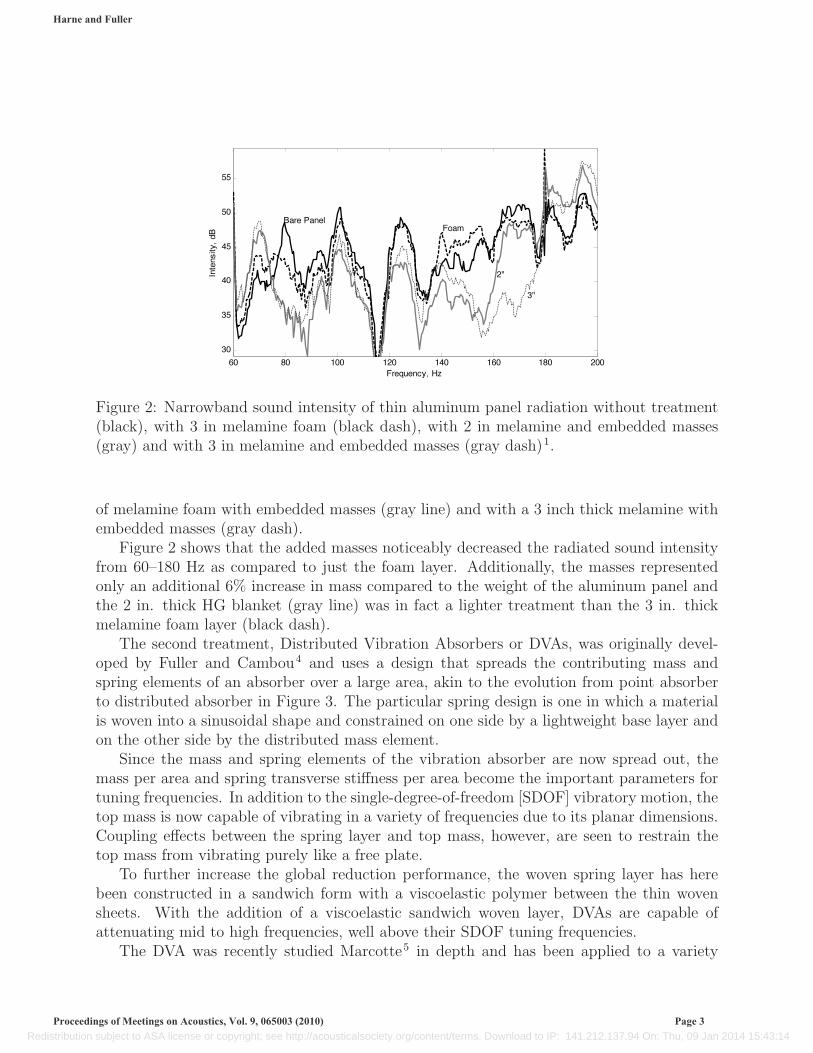
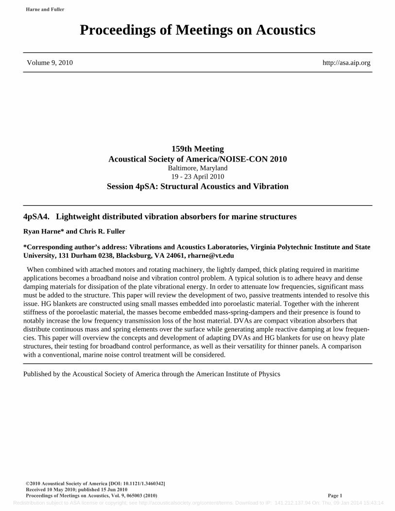
Figure 2: Narrowband sound intensity of thin aluminum panel radiation without treatment(black), with 3 in melamine foam (black dash), with 2 in melamine and embedded masses(gray) and with 3 in melamine and embedded masses (gray dash)1.
of melamine foam with embedded masses (gray line) and with a 3 inch thick melamine withembedded masses (gray dash).
Figure 2 shows that the added masses noticeably decreased the radiated sound intensityfrom 60–180 Hz as compared to just the foam layer. Additionally, the masses representedonly an additional 6% increase in mass compared to the weight of the aluminum panel andthe 2 in. thick HG blanket (gray line) was in fact a lighter treatment than the 3 in. thickmelamine foam layer (black dash).
The second treatment, Distributed Vibration Absorbers or DVAs, was originally devel-oped by Fuller and Cambou4 and uses a design that spreads the contributing mass andspring elements of an absorber over a large area, akin to the evolution from point absorberto distributed absorber in Figure 3. The particular spring design is one in which a materialis woven into a sinusoidal shape and constrained on one side by a lightweight base layer andon the other side by the distributed mass element.
Since the mass and spring elements of the vibration absorber are now spread out, themass per area and spring transverse stiffness per area become the important parameters fortuning frequencies. In addition to the single-degree-of-freedom [SDOF] vibratory motion, thetop mass is now capable of vibrating in a variety of frequencies due to its planar dimensions.Coupling effects between the spring layer and top mass, however, are seen to restrain thetop mass from vibrating purely like a free plate.
To further increase the global reduction performance, the woven spring layer has herebeen constructed in a sandwich form with a viscoelastic polymer between the thin wovensheets. With the addition of a viscoelastic sandwich woven layer, DVAs are capable ofattenuating mid to high frequencies, well above their SDOF tuning frequencies.
The DVA was recently studied Marcotte5 in depth and has been applied to a variety
Harne and Fuller
Proceedings of Meetings on Acoustics, Vol. 9, 065003 (2010) Page 3
Redistribution subject to ASA license or copyright; see http://acousticalsociety.org/content/terms. Download to IP: 141.212.137.94 On: Thu, 09 Jan 2014 15:43:14
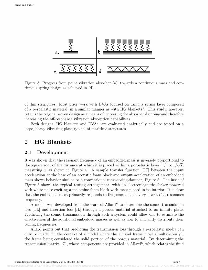
Figure 3: Progress from point vibration absorber (a), towards a continuous mass and con-tinuous spring design as achieved in (d).
of thin structures. Most prior work with DVAs focused on using a spring layer composedof a poroelastic material, in a similar manner as with HG blankets5. This study, however,retains the original woven design as a means of increasing the absorber damping and thereforeincreasing the off-resonance vibration absorption capabilities.
Both designs, HG blankets and DVAs, are evaluated analytically and are tested on alarge, heavy vibrating plate typical of maritime structures.
2 HG Blankets
2.1 Development
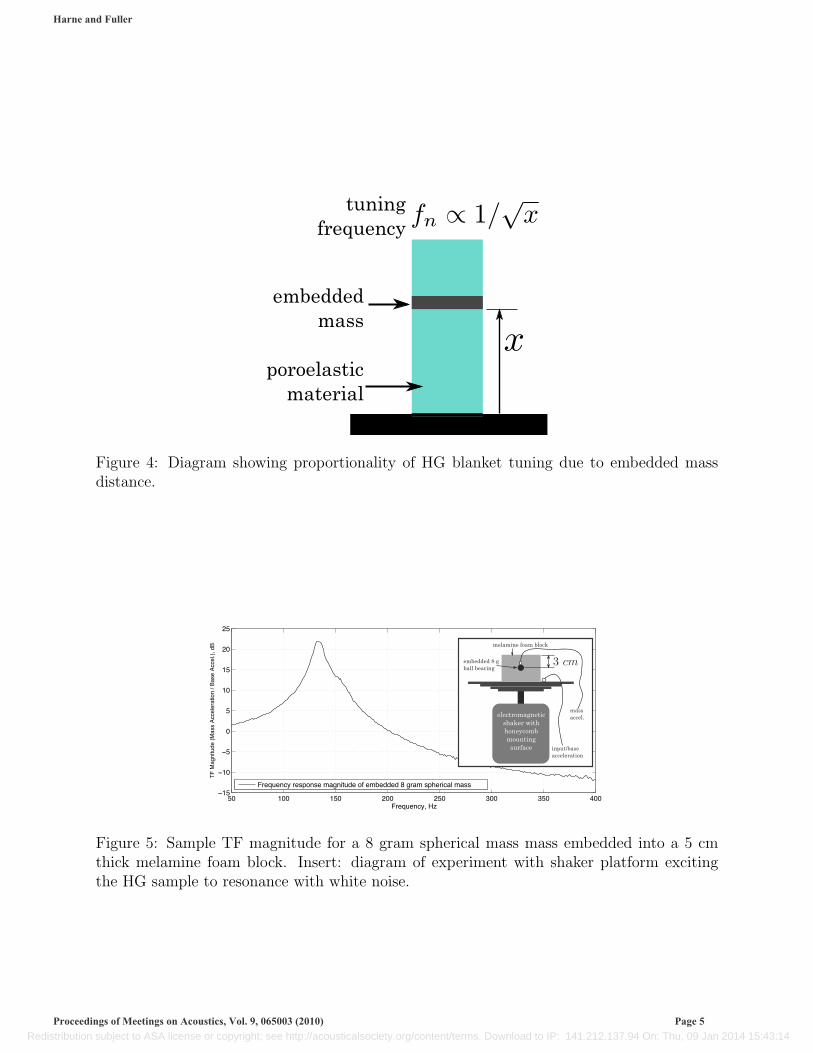
It was shown that the resonant frequency of an embedded mass is inversely proportional tothe square root of the distance at which it is placed within a poroelastic layer3, fn ∝ 1/
√x,
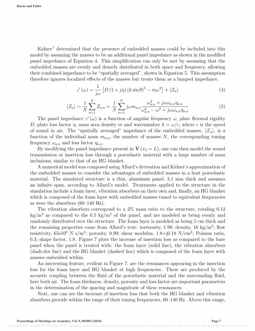
measuring x as shown in Figure 4. A sample transfer function [TF] between the inputacceleration at the base of an acoustic foam block and output acceleration of an embeddedmass shows behavior similar to a conventional mass-spring-damper, Figure 5. The inset ofFigure 5 shows the typical testing arrangement, with an electromagnetic shaker poweredwith white noise exciting a melamine foam block with mass placed in its interior. It is clearthat the embedded mass primarily responds to frequencies at or very near to its resonancefrequency.
A model was developed from the work of Allard6 to determine the sound transmissionloss [TL] and insertion loss [IL] through a porous material attached to an infinite plate.Predicting the sound transmission through such a system could allow one to estimate theeffectiveness of the additional embedded masses as well as how to efficiently distribute theirtuning frequencies.
Allard points out that predicting the transmission loss through a poroelastic media canonly be made “in the context of a model where the air and frame move simultaneously”,the frame being considered the solid portion of the porous material. By determining thetransmission matrix, [T ], whose components are provided in Allard6, which relates the fluid
Harne and Fuller
Proceedings of Meetings on Acoustics, Vol. 9, 065003 (2010) Page 4
Redistribution subject to ASA license or copyright; see http://acousticalsociety.org/content/terms. Download to IP: 141.212.137.94 On: Thu, 09 Jan 2014 15:43:14
���������������
�� ���������
�������������
Figure 4: Diagram showing proportionality of HG blanket tuning due to embedded massdistance.
50 100 150 200 250 300 350 400�15
�10
�5
0
5
10
15
20
25
Frequency, Hz
TF
Mag
nitu
de (
Mas
s A
ccel
erat
ion
/ Bas
e A
ccel
.), d
B
Frequency response magnitude of embedded 8 gram spherical mass
melamine foam block
embedded 8 gball bearing
electromagneticshaker withhoneycombmounting
surface
massaccel.
input/baseacceleration
Figure 5: Sample TF magnitude for a 8 gram spherical mass mass embedded into a 5 cmthick melamine foam block. Insert: diagram of experiment with shaker platform excitingthe HG sample to resonance with white noise.
Harne and Fuller
Proceedings of Meetings on Acoustics, Vol. 9, 065003 (2010) Page 5
Redistribution subject to ASA license or copyright; see http://acousticalsociety.org/content/terms. Download to IP: 141.212.137.94 On: Thu, 09 Jan 2014 15:43:14

Figure 6: Porous material attached to an infinite plate with incident acoustic field andtransmitted field on side of the plate.
and solid stresses and velocities from one region of the poroelastic media to another region,one can find the transmitted stresses and velocities present at the plate resulting from anincident acoustic field. A diagram of the scenario under study is shown in Figure 6. Thistransmission matrix then relates the stresses and velocities from the incident field, x3 = 0,to those present at the plate, x3 = L.
V (x3 = 0) = [T ]V (x3 = L) (1)
where the vector V is composed of the following quantities:
V (x3) =[vs1 vs3 vf3 σs
33 σs13 σf
33
]T(2)
where vi denotes velocity, σii denotes stress tensor components, s denotes the solid frame, fdenotes the fluid components and T denotes the transpose. In deriving V (x3 = L), both theinfinite panel impedance and the transmission coefficient, W , appear allowing one to thensolve for the transmission loss through the poroelastic and plate system. The diffuse fieldtransmission loss can then be calculated from Equation 3.
TL = −10log10(2
∫ π/2
0
|W (θ) |2 cos θ sin θdθ)
(3)
Allard found that despite the infinite panel assumption, experimental values of transmissionloss for a finite poroelastic and plate system match very closely to the results predicted bythe model.
The insertion loss is calculated with similar ease. The insertion loss is the ratio of soundpressure level with and without the plate/poroelastic system in place from some desiredobservation point or array of points. For primarily dissipative systems, the transmission lossand insertion loss are nearly identical. Full derivation is available in the text6.
Harne and Fuller
Proceedings of Meetings on Acoustics, Vol. 9, 065003 (2010) Page 6
Redistribution subject to ASA license or copyright; see http://acousticalsociety.org/content/terms. Download to IP: 141.212.137.94 On: Thu, 09 Jan 2014 15:43:14
Kidner7 determined that the presence of embedded masses could be included into thismodel by assuming the masses to be an additional panel impedance as shown in the modifiedpanel impedance of Equation 4. This simplification can only be met by assuming that theembedded masses are evenly and densely distributed in both space and frequency, allowingtheir combined impedance to be “spatially averaged”, shown in Equation 5. This assumptiontherefore ignores localized effects of the masses but treats them as a lumped impedance.
z′ (ω) =1
jω
[D (1 + jη) (k sin θ)4 −mω2
]+ 〈Za〉 (4)
〈Za〉 = 1
N
N∑n=1
Za,n =1
N
N∑n=1
jωma,n
ω2a,n + jωωa,nηa,n
ω2a,n − ω2 + jωωa,nηa,n
(5)
The panel impedance z′ (ω) is a function of angular frequency ω, plate flexural rigidityD, plate loss factor η, mass area density m and wavenumber k = ω/c, where c is the speedof sound in air. The “spatially averaged” impedance of the embedded masses, 〈Za〉, is afunction of the individual mass ma,n, the number of masses N , the corresponding tuningfrequency ωa,n and loss factor ηa,n.
By modifying the panel impedance present in V (x3 = L), one can then model the soundtransmission or insertion loss through a poroelastic material with a large number of massinclusions, similar to that of an HG blanket.
A numerical model was composed using Allard’s derivation and Kidner’s approximation ofthe embedded masses to consider the advantages of embedded masses in a host poroelasticmaterial. The simulated structure is a thin, aluminum panel, 3.1 mm thick and assumesan infinite span, according to Allard’s model. Treatments applied to the structure in thesimulation include a foam layer, vibration absorbers on their own and, finally, an HG blanketwhich is composed of the foam layer with embedded masses tuned to equivalent frequenciesas were the absorbers (60–140 Hz).
The vibration absorbers correspond to a 2% mass ratio to the structure, totaling 0.12kg/m2 as compared to the 6.5 kg/m2 of the panel, and are modeled as being evenly andrandomly distributed over the structure. The foam layer is modeled as being 5 cm thick andthe remaining properties come from Allard’s text: tortuosity, 1.98; density, 16 kg/m3; flowresistivity, 65e103 N s/m4; porosity, 0.99; shear modulus, 1.8+j0.18 N/cm2; Poisson ratio,0.3; shape factor, 1.8. Figure 7 plots the increase of insertion loss as compared to the barepanel when the panel is treated with: the foam layer (solid line), the vibration absorbers(dash-dot line) and the HG blanket (dashed line) which is composed of the foam layer withmasses embedded within.
An interesting feature, evident in Figure 7, are the resonances appearing in the insertionloss for the foam layer and HG blanket at high frequencies. These are produced by theacoustic coupling between the fluid of the poroelastic material and the surrounding fluid,here both air. The foam thickness, density, porosity and loss factor are important parametersin the determination of the spacing and magnitude of these resonances.
Next, one can see the increase of insertion loss that both the HG blanket and vibrationabsorbers provide within the range of their tuning frequencies, 60–140 Hz. Above this range,
Harne and Fuller
Proceedings of Meetings on Acoustics, Vol. 9, 065003 (2010) Page 7
Redistribution subject to ASA license or copyright; see http://acousticalsociety.org/content/terms. Download to IP: 141.212.137.94 On: Thu, 09 Jan 2014 15:43:14

�� ��� �� �� ���� �� ��� ����
�
�
�
�
�
�
�
�
�������������
����
����
�����
����
�!���
"���
��#$
�
�
���%�&���������%��'!��*!+���!����+���+����-�$&�����
Figure 7: Increase of insertion loss for the thin panel when the treatment is a foam layer(solid line), vibration absorbers tuned from 60–140 Hz (dash-dot line) and an HG blanket(dashed line).
Table 1: Properties of foam layer used in simulationThickness [m] Density [kg ·m−3]
0.07 30
Bulk Modulus [kPa] Flow Resistivity [kPa · s ·m−2]79 11.89
however, the vibration absorbers lose the capacity to alter the insertion loss of the structuresince at frequencies well above their resonance the absorbers appear merely as a small addedmass to the host structure.
Finally, the HG blanket is seen to benefit from both the classical vibration absorberresponse as well as the host poroelastic material damping effects at high frequencies. TheHG blanket overcomes the requirement of adding significant foam layer mass to achieve lowfrequency attenuation by adding a minor amount of solid, point masses into the foam whichact as an array of vibration absorbers.
Next, a model was constructed to emulate an experiment performed earlier in which theusefulness of embedded masses in a foam layer attached to an acoustically-excited, thin,lightly damped plate was evaluated3. The foam material was modeled with the propertiesof Table 1. The panel was of dimensions 1.11 m by 1.11 m with a total mass of 3.4 kg.The HG blanket masses represented an additional 0.4 kg to the structure—11% of the panelmass—and were modeled as having tuning frequencies evenly spread from 60 to 140 Hz tosatisfy the modeling assumptions.
Figure 8 presents the model results, comparing the insertion loss of the HG blanket withpanel with that of the bare foam layer and panel, plotted in 1/3 octave bands from 63 Hz to
Harne and Fuller
Proceedings of Meetings on Acoustics, Vol. 9, 065003 (2010) Page 8
Redistribution subject to ASA license or copyright; see http://acousticalsociety.org/content/terms. Download to IP: 141.212.137.94 On: Thu, 09 Jan 2014 15:43:14

63 80 100 160 250 400 630 1k 2k0
5
10
15
20
25
30
Frequency, Hz
Inse
rtio
n Lo
ss, d
B
Predicted Panel and Foam ILPredicted Panel and HG Blanket IL
Figure 8: Modeled insertion loss of the foam layer and panel (solid line) and of the HGblanket and panel (dashed line).
2 kHz. The simulation shows a steady increase in insertion loss of the panel and foam layertreatment as one considers higher and higher frequencies. However, the HG blanket providesan increase in IL as compared to just the foam and panel system—an average increase of 4.9dB from the 80–160 Hz 1/3 octave bands, a maximum of 5.5 dB for the 80 Hz 1/3 octaveband. At frequencies well above the tuning frequencies for the masses, the plots converge asexpected since the additional, embedded vibration absorbers are not excited in that range.
The test that the above model depicted, described by Kidner3, utilized 50 spherical, 8gram masses for the HG blanket, locating them randomly throughout the foam layer. Thefoam material tested was Willtec foam, as manufactured by Illbruck, with characteristicproperties as provided in Table 1. The results of the test are shown in Figure 9 and comparequalitatively well with the trends of Figure 8. The difference in IL between the HG blanketand panel system and the foam and panel system is provided in Table 2.
The simulation, in fact, under-predicted the benefit of the embedded masses to increasethe low frequency transmission loss as Table 2 shows the average IL of the experiment to havebeen greater than that for the model, for the 1/3 octave bands from 80–160 Hz. Figure 9also reveals the convergence of the HG blanket IL back down to the level of just the foamand panel system at high frequencies. The benefit of the sound control treatment at highfrequencies is then limited to the attenuation capabilities of the poroelastic material itself.
An interesting effect appears in the experiment around the 200 Hz 1/3 octave band. TheIL of the HG blanket temporarily drops beneath the level produced by just the foam. This
Harne and Fuller
Proceedings of Meetings on Acoustics, Vol. 9, 065003 (2010) Page 9
Redistribution subject to ASA license or copyright; see http://acousticalsociety.org/content/terms. Download to IP: 141.212.137.94 On: Thu, 09 Jan 2014 15:43:14

63 80 100 160 250 400 630 1k 2k-10
-5
0
5
10
15
20
25
30
Frequency, Hz
Inse
rtio
n Lo
ss, d
BMeasured Panel and Foam ILMeasured Panel and HG Blanket IL
Figure 9: Experimental insertion loss of the foam layer and panel (solid line) and of the HGblanket and panel (dashed line)3.
Table 2: Change in insertion loss from panel and foam case to panel and HG blanket scenariofor given 1/3 octave band
80 Hz 100 Hz 125 Hz 160 HzModel +5.5 dB +5.2 dB +4.9 dB +4.1 dB
Experiment +4 dB +15 dB +9 dB 0 dB
Average 80–160 HzModel +4.9 dB
Experiment +7 dB
Harne and Fuller
Proceedings of Meetings on Acoustics, Vol. 9, 065003 (2010) Page 10
Redistribution subject to ASA license or copyright; see http://acousticalsociety.org/content/terms. Download to IP: 141.212.137.94 On: Thu, 09 Jan 2014 15:43:14

Figure 10: HG piece tested with constant foam thickness (left) and varied foam thickness(right) with dots representing accelerometer measuring locations.
effect does not emerge from the simulation and is likely due to a coupling effect betweenthe masses and surrounding foam. As with most multi-body systems, some dynamics mayproduce in-phase motion, here evidenced by a sudden drop in IL given that the fluid motionand embedded masses are likely oscillating in-phase.
Nevertheless, both the experimental and simulated results show that embedded mediawithin the poroelastic material will increase the low frequency attenuation capability of thehost material at frequencies to which the masses were tuned. This encourages one to designan HG blanket which is tuned to the widest frequency range possible for a given target massratio desired for the HG blanket treatment.
2.2 Mass Inclusion Optimization
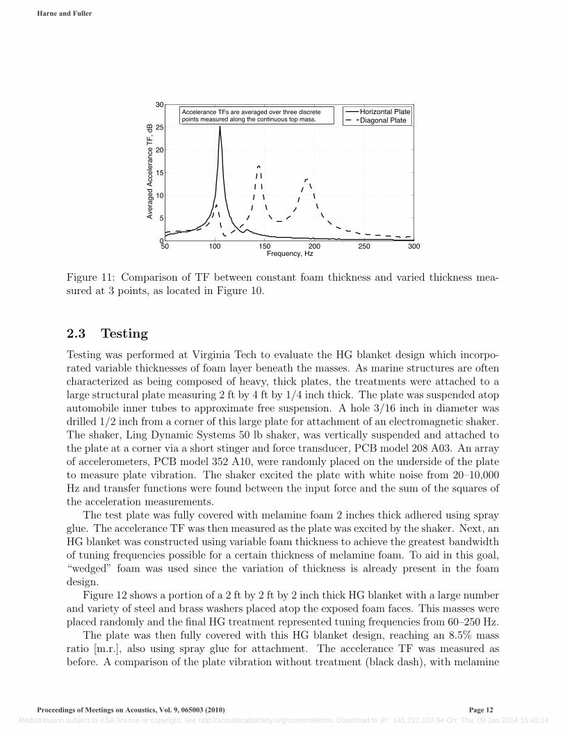
One method to achieve a wide tuning frequency range is to design an HG blanket whichutilizes a large proportion of the foam thickness available. Figure 10 shows the differencebetween a small HG sample with a uniform foam thickness and the same HG sample with avariable foam thickness beneath the mass. In this instance, a continuous mass was used fortesting such that mass per area and stiffness per area characteristics play a role in determiningthe SDOF tuning frequency.
Figure 11 shows the transfer functions for 3 measured points on the top of the samples ofFigure 10, where the TF is between the base input acceleration and the sum of the squaresof the output accelerations. The case of constant foam thickness below the mass layer showsa single resonance. Interestingly, even though the mass is continuous, the 3 measuring pointsof the variable thickness sample produce 3 unique SDOF resonance frequencies, suggestinga continuum of resonance frequencies is present, the bandwidth of these frequencies beingdefined by the variation of mass per area and stiffness per area along the absorber’s variedthickness axis. The objective is design is thus to exploit this potential range of “tuningfrequencies”.
Harne and Fuller
Proceedings of Meetings on Acoustics, Vol. 9, 065003 (2010) Page 11
Redistribution subject to ASA license or copyright; see http://acousticalsociety.org/content/terms. Download to IP: 141.212.137.94 On: Thu, 09 Jan 2014 15:43:14
50 100 150 200 250 3000
5
10
15
20
25
30
Frequency, Hz
Ave
rage
d A
ccel
eran
ce T
F, d
B
Horizontal PlateDiagonal Plate
Accelerance TFs are averaged over three discretepoints measured along the continuous top mass.
Figure 11: Comparison of TF between constant foam thickness and varied thickness mea-sured at 3 points, as located in Figure 10.
2.3 Testing
Testing was performed at Virginia Tech to evaluate the HG blanket design which incorpo-rated variable thicknesses of foam layer beneath the masses. As marine structures are oftencharacterized as being composed of heavy, thick plates, the treatments were attached to alarge structural plate measuring 2 ft by 4 ft by 1/4 inch thick. The plate was suspended atopautomobile inner tubes to approximate free suspension. A hole 3/16 inch in diameter wasdrilled 1/2 inch from a corner of this large plate for attachment of an electromagnetic shaker.The shaker, Ling Dynamic Systems 50 lb shaker, was vertically suspended and attached tothe plate at a corner via a short stinger and force transducer, PCB model 208 A03. An arrayof accelerometers, PCB model 352 A10, were randomly placed on the underside of the plateto measure plate vibration. The shaker excited the plate with white noise from 20–10,000Hz and transfer functions were found between the input force and the sum of the squares ofthe acceleration measurements.
The test plate was fully covered with melamine foam 2 inches thick adhered using sprayglue. The accelerance TF was then measured as the plate was excited by the shaker. Next, anHG blanket was constructed using variable foam thickness to achieve the greatest bandwidthof tuning frequencies possible for a certain thickness of melamine foam. To aid in this goal,“wedged” foam was used since the variation of thickness is already present in the foamdesign.
Figure 12 shows a portion of a 2 ft by 2 ft by 2 inch thick HG blanket with a large numberand variety of steel and brass washers placed atop the exposed foam faces. This masses wereplaced randomly and the final HG treatment represented tuning frequencies from 60–250 Hz.
The plate was then fully covered with this HG blanket design, reaching an 8.5% massratio [m.r.], also using spray glue for attachment. The accelerance TF was measured asbefore. A comparison of the plate vibration without treatment (black dash), with melamine
Harne and Fuller
Proceedings of Meetings on Acoustics, Vol. 9, 065003 (2010) Page 12
Redistribution subject to ASA license or copyright; see http://acousticalsociety.org/content/terms. Download to IP: 141.212.137.94 On: Thu, 09 Jan 2014 15:43:14

Figure 12: HG blanket constructed from wedged acoustic foam with embedded masses tunedfrom 60–250 Hz.
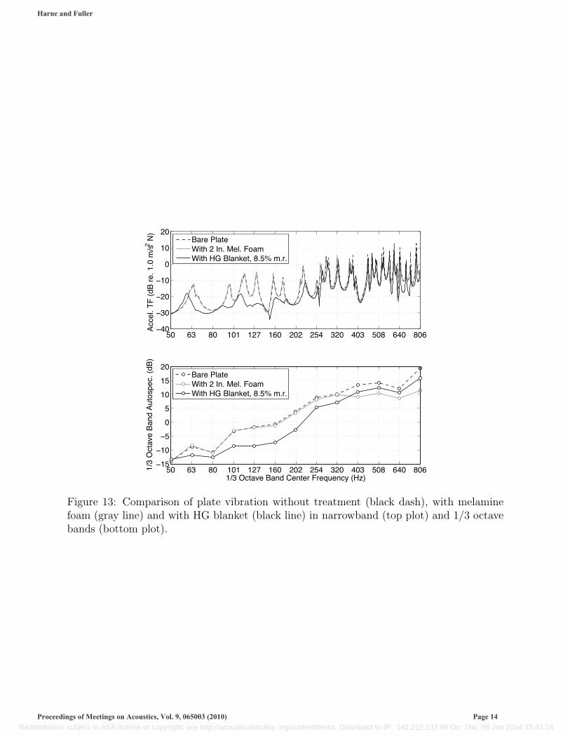
foam (gray line) and with HG blanket (black line) is shown in Figure 13.The melamine foam itself attenuates little to no vibration at frequencies less than 300
Hz. In the range of its tuning frequencies, the HG blanket provides attenuation on the orderof 5–7 dB in 1/3 octave bands. The narrowband plot shows that the HG blanket reduces theplate resonances on the order of 5–18 dB. Since the melamine foam and HG blanket wereboth 2 inches thick, the addition of the masses in the HG blanket are seen to significantlyincrease low frequency absorption, at a cost of an additional 7.5% of the plate mass (thefoam itself totaled 1% of the plate mass). The HG blanket absorber design therefore takesadvantage of the inherent elasticity of the porous media to suppress low frequency vibrationwhich the poroelastic is unable to attenuate on its own and widening the tuning frequencyrange using a varying thickness of foam layer allows for maximum passive attenuation.
3 Distributed Vibration Absorbers
3.1 Development
The original design of the DVA, described in detail by Cambou4, was intended for a combi-nation of active and passive noise control, using a piezoelectric film as the choice woven layerallowing the distributed active vibration absorber [DAVA] to be electronically controlled. Inthe current study, however, active elements were removed to pursue a versatile form factornot hindered by control design complexity.
The DVA is composed of four, basic elements (Figure 14): (i) a continuous top mass, (ii)a continuous woven spring, (iii) a base layer and (iv) some method for adhering the joints
Harne and Fuller
Proceedings of Meetings on Acoustics, Vol. 9, 065003 (2010) Page 13
Redistribution subject to ASA license or copyright; see http://acousticalsociety.org/content/terms. Download to IP: 141.212.137.94 On: Thu, 09 Jan 2014 15:43:14
50 63 80 101 127 160 202 254 320 403 508 640 806�40
�30
�20
�10
0
10
20
Acc
el. T
F (
dB r
e. 1
.0 m
/s2 N
)
50 63 80 101 127 160 202 254 320 403 508 640 806�15
�10
�5
0
5
10
15
20
1/3 Octave Band Center Frequency (Hz)
1/3
Oct
ave
Ban
d A
utos
pec.
(dB
)
Bare PlateWith 2 In. Mel. FoamWith HG Blanket, 8.5% m.r.
Bare PlateWith 2 In. Mel. FoamWith HG Blanket, 8.5% m.r.
Figure 13: Comparison of plate vibration without treatment (black dash), with melaminefoam (gray line) and with HG blanket (black line) in narrowband (top plot) and 1/3 octavebands (bottom plot).
Harne and Fuller
Proceedings of Meetings on Acoustics, Vol. 9, 065003 (2010) Page 14
Redistribution subject to ASA license or copyright; see http://acousticalsociety.org/content/terms. Download to IP: 141.212.137.94 On: Thu, 09 Jan 2014 15:43:14

Figure 14: The elements of the DVA.
Figure 15: Sample DVA piece with steel and viscoelastic woven layer.
together. A variety of adhesive, epoxy and metal bonding techniques have been evaluatedin this study and the selection of adhering method is ultimately decided based on one’smanufacturing restrictions or tuning goals.
Tuning of the DVA can be accomplished by modifying: (i) the top mass area density,(ii) the woven wavelength in the spring layer, (iii) the weave material thickness and (iv)by choice of adhesive method. The damping of the DVA is also a product of the adhesivechoice, notably a function of how soft or firm the joints become after a bond is made. In thisstudy, damping was added in the form of a viscoelastic damping polymer sandwich withinthe woven layer.
Figure 15 shows a sample DVA with a perforated steel mass, steel and viscoelastic wovenlayer and a steel base layer. The viscoelastic layer—placed in between two strips of 0.001inch thick steel—is too thin to be evident in the photo. The adhesive used to hold the parttogether was a high-strength epoxy, chosen so as to require as little epoxy as possible sinceit can contribute to increasing the total mass.
A sample DVA TF is shown in Figure 16 showing, just like for an embedded mass inmelamine foam of Figure 5, a clear SDOF resonance. This DVA was identical to thatpictured in Figure 15 but did not contain a viscoelastic sandwich woven layer. The wovenspring layer was a single, thin metal strip. Thus, this TF is expected to be narrower in
Harne and Fuller
Proceedings of Meetings on Acoustics, Vol. 9, 065003 (2010) Page 15
Redistribution subject to ASA license or copyright; see http://acousticalsociety.org/content/terms. Download to IP: 141.212.137.94 On: Thu, 09 Jan 2014 15:43:14

�� ��� ��� ��� ��� ��� ��� �����
��
�
�
�
��
��
���
����
����
���
�������������
�
�
���� ��!"#���� ������
Figure 16: Sample DVA TF for piece tuned to 165 Hz.
bandwidth at resonance than that resulting from the piece with the visco sandwich springdesign.
Since the original development, most DVA designs that were studied used acoustic foam asthe spring layer. There is an advantage, however, in using the woven spring approach of thisstudy as opposed to a poroelastic “spring” for the DVA design. It is known that damping is animportant low-mass method of increasing the absorber’s response at frequencies away fromresonance8. Unfortunately, the damping characteristics of a foam material are inherentlyfixed, being a characteristic property of the poroelastic material itself. In light of achievingboth a tunable absorber design and the possibility of global vibration control with increaseddamping, the woven spring design has an advantage over using a poroelastic material as thespring layer.
Thus, this project returned to the original woven spring layer design which was deemedmore versatile in this respect. The viscoelastic sandwich woven layer could then be tested forits benefit over the standard thin woven layer, particularly in terms of off-resonance vibrationabsorption. Other locations for the viscoelastic layer have been considered—covering thebottom surface of the mass or covering the top surface of the base layer with the visco, forexample—but only the woven layer sandwich design will be discussed here.
3.2 Testing
Given the size of the plate to which these DVAs would be attached, a large number wereconstructed all using the same top mass dimensions, 6 inches by 12 inches. For full platecoverage, this would require 16 pieces in total. A variety of steel and aluminum sheetsof perforated metal were available, representing several area densities. The DVAs were alsoconstructed with several woven layer wavelength dimensions and steel sheet thicknesses. Thisresulted in DVAs with unique tuning frequencies, ranging from 80–400 Hz. Perforated masseswere preferred over solid masses in light of knowledge that air pumping effects can generatehigh frequency damping resulting from the turbulent flow through the perforations9. Theperforations also play a role in decreasing the radiation efficiency of the DVAs such that the
Harne and Fuller
Proceedings of Meetings on Acoustics, Vol. 9, 065003 (2010) Page 16
Redistribution subject to ASA license or copyright; see http://acousticalsociety.org/content/terms. Download to IP: 141.212.137.94 On: Thu, 09 Jan 2014 15:43:14

Figure 17: DVA treatment attached to heavy test plate.
vibrating absorbers do not themselves become sources of noise.To compare the advantage a viscoelastic sandwich woven layer design provides, one batch
of DVAs was created with the viscoelastic sandwich layer and one without, the latter usingjust a single thin woven layer. The DVA treatment using just a thin woven layer had a m.r.of 9.1% while the DVA set with the visco sandwich woven layer had a m.r. of 10%.
No optimization strategy was used for placing the DVAs onto the plate; rather, they wereplaced wherever there was available room. As with the HG blankets, spray glue was usedto secure the DVAs to the plate. Figure 17 shows the DVA treatment that used the viscosandwich layer. It should be noted that only 15 DVA pieces were actually used on the platefor each treatment since the shaker attachment to the plate inhibited access to the plate topsurface.
The performance of both DVA treatments was evaluated in a similar manner as was donewith the HG blankets—attachment to the test plate, shaking the plate with white noiseand taking the accelerance TF with and without treatments present. Figure 18 shows acomparison of the plate vibration with no treatment (black dash), with the DVA treatmentof 9.1% m.r. (gray line) and with the DVA treatment of 10% m.r. which used the viscosandwich design (black line).
It is clear that over the range of their tuning frequencies, both DVA treatments reduce the
Harne and Fuller
Proceedings of Meetings on Acoustics, Vol. 9, 065003 (2010) Page 17
Redistribution subject to ASA license or copyright; see http://acousticalsociety.org/content/terms. Download to IP: 141.212.137.94 On: Thu, 09 Jan 2014 15:43:14

50 63 80 101 127 160 202 254 320 403 508 640 806�40
�30
�20
�10
0
10
20
Acc
el. T
F (
dB r
e. 1
.0 m
/s2 N
)
50 63 80 101 127 160 202 254 320 403 508 640 806�70
�60
�50
�40
�30
1/3 Octave Band Center Frequency (Hz)
1/3
Oct
ave
Ban
d A
utos
pec.
(dB
)
Bare PlateWith DVAs, 9.1% m.r.With DVAs w/ visco, 10% m.r.
Bare PlateWith DVAs, 9.1% m.r.With DVAs w/ visco, 10% m.r.
Figure 18: Comparison of plate vibration without treatment (black dash), with DVAs of9.1% m.r. (gray line) and with DVAs of 10% m.r. using visco (black line) in narrowband(top plot) and 1/3 octave bands (bottom plot).
Harne and Fuller
Proceedings of Meetings on Acoustics, Vol. 9, 065003 (2010) Page 18
Redistribution subject to ASA license or copyright; see http://acousticalsociety.org/content/terms. Download to IP: 141.212.137.94 On: Thu, 09 Jan 2014 15:43:14

806 1016 1280 1613 2032 2560 3225 4064 5120�40
�35
�30
�25
�20
�15
1/3 Octave Band Center Frequency (Hz)
1/3
Oct
ave
Ban
d A
utos
pec.
(dB
)
Bare PlateWith DVAs, 9.1% m.r.With DVAs w/ visco, 10% m.r.
Figure 19: Comparison of plate vibration without treatment (blue dashed), with DVAs of9.1% m.r. (green solid) and with DVAs of 10% m.r. using visco (red solid) in 1/3 octavebands at high frequencies.
plate’s response by as much as 20 dB from resonance magnitudes in narrowband. However,from the 1/3 octave band comparison, the DVAs using the viscoelastic sandwich woven layerprovide greater global attenuation, an average of 7 dB from 100–400 Hz. While both DVAstreatments were tuned over the same bandwidth, 80–400 Hz, the treatment which used thevisco is seen to outperform the treatment lacking it.
Furthermore, considering higher frequencies, Figure 19 shows that the attenuation ofplate vibration is not limited to just the tuning frequency region. The 10% m.r. DVAtreatment suppresses vibration by 5 dB or greater at frequencies greater than 1,000 Hz.
In the frequency range plotted in Figure 19, it is seen that the disparity of performancebetween the DVA treatments decreases in this bandwidth. This suggests that the DVAdesign itself, and not simply the viscoelastic layer, plays a role in generating global vibrationreduction. This high frequency damping is currently hypothesized as being produced by airpumping effects through the perforations and/or through the woven layer cavities.
4 Comparison
To assess how well HG blankets and DVAs perform against a commercially available producta conventional noise control tile treatment was acquired. The “damping tiles” used here area composite material and are available in standardized sizes. The tile area density was muchgreater than that of the HG blanket or DVA treatments. When fully covering the plate—aswas tested for HG blankets and the DVAs—the damping tile treatment produced a massratio of 30%.
The damping tiles were applied to the heavy plate and tested as before for the previousabsorber treatments. A comparison of the low frequency performance of plate vibrationattenuation is shown in Figure 20. At frequencies less than 250 Hz, all three treatmentsproduce similar amounts of vibration reduction. This is significant if one considers that
Harne and Fuller
Proceedings of Meetings on Acoustics, Vol. 9, 065003 (2010) Page 19
Redistribution subject to ASA license or copyright; see http://acousticalsociety.org/content/terms. Download to IP: 141.212.137.94 On: Thu, 09 Jan 2014 15:43:14

50 63 80 101 127 160 202 254 320 403�50
�40
�30
�20
�10
0
10
Acc
el. T
F (
dB r
e. 1
.0 m
/s2 N
)
50 63 80 101 127 160 202 254 320 403�70
�65
�60
�55
�50
�45
�40
�35
1/3 Octave Band Center Frequency (Hz)
1/3
Oct
ave
Ban
d A
utos
pec.
(dB
)
Bare PlateWith HG Blanket 8.5% m.r.W/ DVAs w/ visco 10% m.r.W/ commercial tiles 30% m.r.
Bare PlateWith HG Blanket 8.5% m.r.W/ DVAs w/ visco 10% m.r.W/ commercial tiles 30% m.r.
Figure 20: Comparison of plate vibration without treatment (blue dashed), with HG blan-ket (cyan solid), with DVAs using visco (red solid) and commercial tiles (black solid) innarrowband (top plot) and 1/3 octave bands (bottom plot).
the DVA and HG treatments tested were roughly one-third the mass of the commercial tiletreatment. For applications where minimizing weight is a priority, both HG blankets andDVAs provide a viable solution to achieving low frequency noise control.
An additional benefit of both DVA and HG treatments is the ability to easily tune suchabsorbers to a certain bandwidth of important frequencies. Many commercially availablesound absorbing treatments do not provide for this flexibility and would therefore requiremore mass to be added to the structure to achieve absorption in this low frequency range.
5 Conclusions
Two new vibration absorber designs were considered for their low frequency passive soundabsorption. HG blankets were modeled and found to have significant absorption over theirtuning frequency range. As a result, HG blankets were constructed with a design thatmaximized the bandwidth of tuning achievable for a given foam thickness. A lightweight
Harne and Fuller
Proceedings of Meetings on Acoustics, Vol. 9, 065003 (2010) Page 20
Redistribution subject to ASA license or copyright; see http://acousticalsociety.org/content/terms. Download to IP: 141.212.137.94 On: Thu, 09 Jan 2014 15:43:14
HG blanket was created and compared against a foam layer of equivalent thickness. The HGblanket was found to decrease plate vibration by 5–7 dB over the range of tuning frequencies,in 1/3 octave bands, but as much as 18 dB off of the plate resonance magnitudes. The HGblanket design significantly increased the vibration absorption of the foam layer at frequenciesless than 250 Hz.
DVAs using a continuous spring layer and continuous mass layer were designed and testedin a like manner. To evaluate the benefit of a viscoelastic sandwich in the woven spring layer,one DVA treatment was constructed with this visco and one without. Perforated continuousmasses were chosen to increase mid to high frequency damping due to possible turbulenceand air pumping effects.
When applied to attenuate plate vibration, DVAs with the viscoelastic spring designaveraged 7 dB of vibration reduction from 100–400 Hz and were also capable of more than5 dB of global attenuation at frequencies above 1,000 Hz. The DVA treatment without theviscoelastic spring still showed significant high frequency attenuation suggesting that theDVA design itself, and not merely the visco, contributed to the global vibration reduction.
A comparison was performed amongst HG blankets, DVAs with the visco layer and acommercial tile treatment. It was found that at frequencies less than 250 Hz, the HGblankets and DVAs performed equally well or better than the damping tiles, even thoughthe DVAs and HG treatments were three times lighter, by mass, than the tiles. DVAs andHG blankets therefore provide significant low frequency vibration absorption for a small costin additional weight to the structure.
6 Acknowledgments
The authors are grateful for the support of Northrop Grumman Shipbuilding, Newport News(NGSB-NN) over the course of this project.
References
[1] C. Fuller, M. Kidner, X. Li, and C. Hansen, “Active-passive heterogeneous blanketsfor control of vibration and sound radiation”, in Proceedings of the 2004 InternationalSymposium on Active Control of Sound and Vibration (Williamsburg, Virginia) (2004).
[2] K. Idrisi, “Heterogeneous (HG) blankets for improved aircraft interior noise reduction”,Ph.D. thesis, Virginia Polytechnic Institute and State University, Blacksburg, Virginia(2008).
[3] M. Kidner, C. Fuller, and B. Gardner, “Increase in transmission loss of single panels byaddition of mass inclusions to a poro-elastic layer: Experimental investigation”, J. SoundVib. 294, 466–472 (2006).
Harne and Fuller
Proceedings of Meetings on Acoustics, Vol. 9, 065003 (2010) Page 21
Redistribution subject to ASA license or copyright; see http://acousticalsociety.org/content/terms. Download to IP: 141.212.137.94 On: Thu, 09 Jan 2014 15:43:14

[4] C. Fuller and P. Cambou, “An active-passive distributed vibration absorber for vibrationand sound radiation control”, J. Acoust. Soc. Am. 104, 1851 (1998).
[5] P. Marcotte, “A study of distributed active vibration absorbers (DAVA)”, Ph.D. thesis,Virginia Polytechnic Institute and State University, Blacksburg, Virginia (2004).
[6] J. Allard, Propagation of Sound in Porous Media. Modelling Sound Absorbing Materials(Elsevier Applied Science, New York, New York) (1993).
[7] M. Kidner, C. Howard, and B. Gardner, “Improvements in panel insertion loss by ad-dition of random masses embedded in a poro-elastic layer: modelling procedures.”, inProceedings of the Twelfth International Congress on Sound and Vibration (Lisbon, Por-tugal) (2005).
[8] C. Fuller, J. Maillard, M. Mercadal, and A. vonFlotow, “Control of aircraft interior noiseusing globally detuned vibration absorbers”, J. Sound Vib. 203, 745–761 (1997).
[9] B. Munson, D. Young, and T. Okiishi, Fundamentals of Fluid Mechanics, third edition(Wiley, University of Michigan) (1998).
Harne and Fuller
Proceedings of Meetings on Acoustics, Vol. 9, 065003 (2010) Page 22
Redistribution subject to ASA license or copyright; see http://acousticalsociety.org/content/terms. Download to IP: 141.212.137.94 On: Thu, 09 Jan 2014 15:43:14