
Harmonics and PFC
27
Harmonics and PFC The love story By Pol Nisenblat
description
Harmonics and PFC. The love story By Pol Nisenblat. THE FUTURE OF POWER QUALITY. DEFINITIONS. PROBLEMS. “DETUNED” SOLUTIONS. TUNED SOLUTIONS. HOW TO CHOOSE. OPEN DISCUSSION. ELECTRICAL POWER SOURCE. - PowerPoint PPT Presentation
Transcript of Harmonics and PFC

Harmonics and PFC The love story
By Pol Nisenblat
2
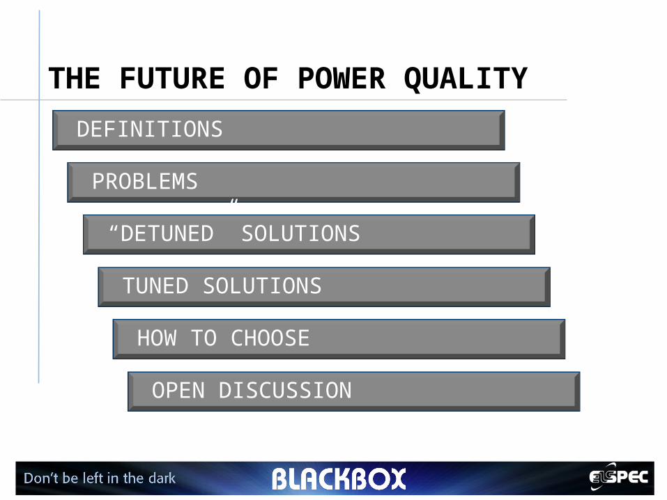
THE FUTURE OF POWER QUALITY
DEFINITIONS
PROBLEMS
“DETUNED” SOLUTIONS
TUNED SOLUTIONS
HOW TO CHOOSE
OPEN DISCUSSION
3
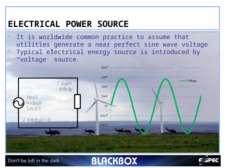
ELECTRICAL POWER SOURCE It is worldwide common practice to assume that utilities
generate a near perfect sine wave voltage Typical electrical energy source is introduced by “voltage”
source
Ideal Voltage Source
Z internal = 0
Z load = infinity
4
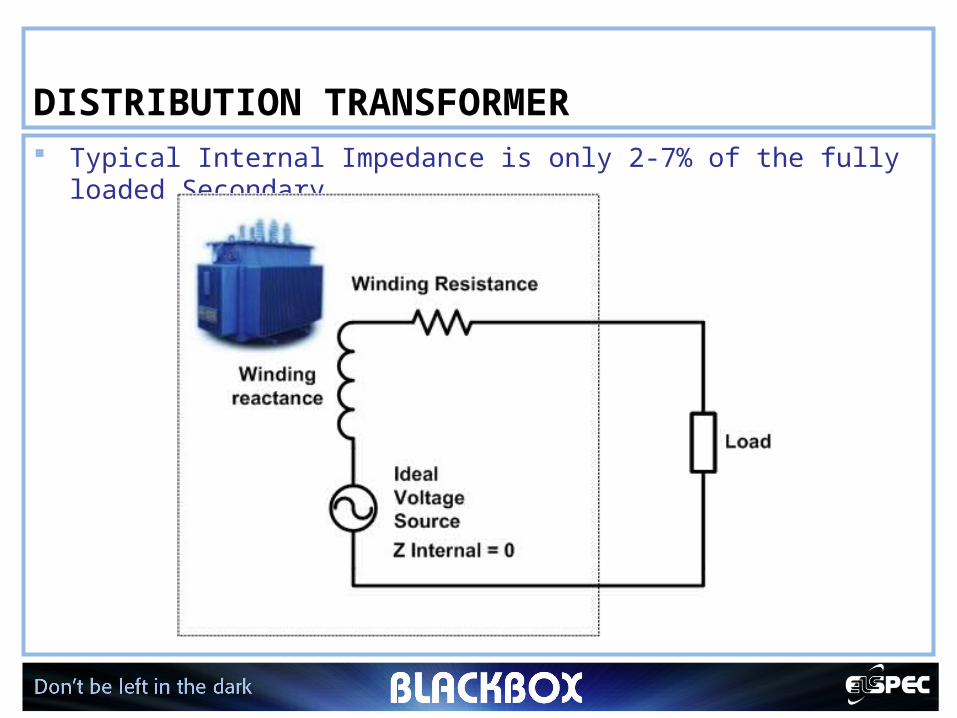
DISTRIBUTION TRANSFORMER Typical Internal Impedance is only 2-7% of the fully loaded
Secondary
5
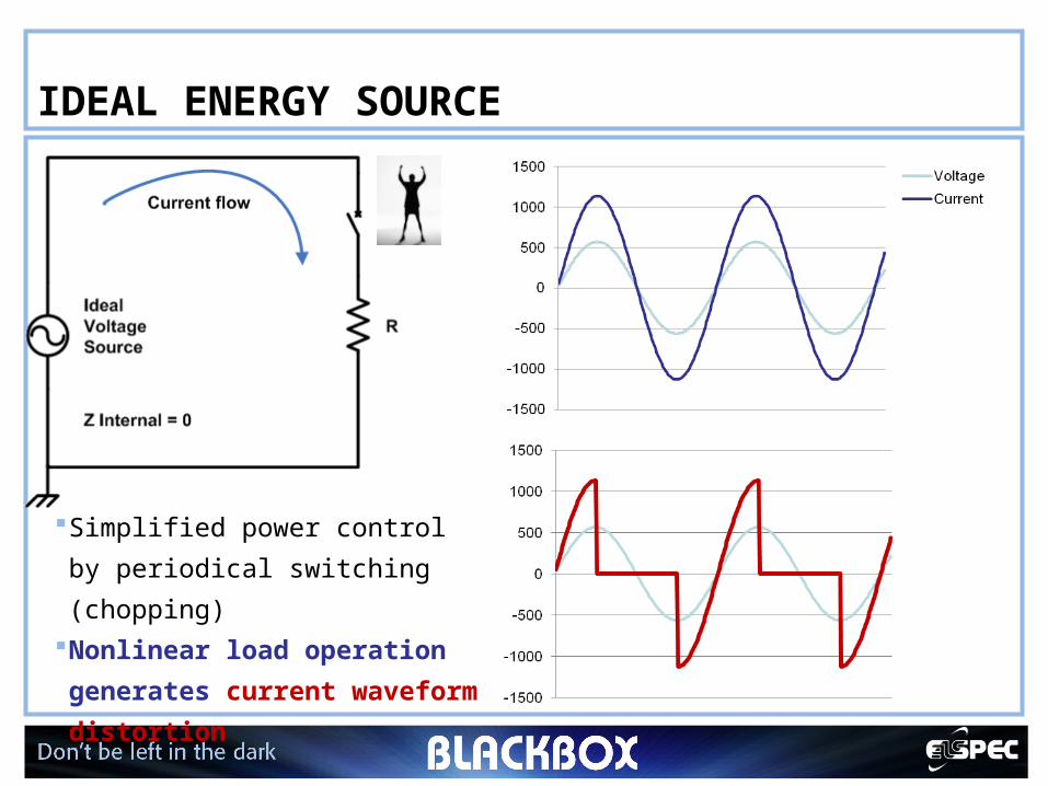
IDEAL ENERGY SOURCE
Simplified power control by
periodical switching (chopping)Nonlinear load operation
generates current
waveform distortion
6
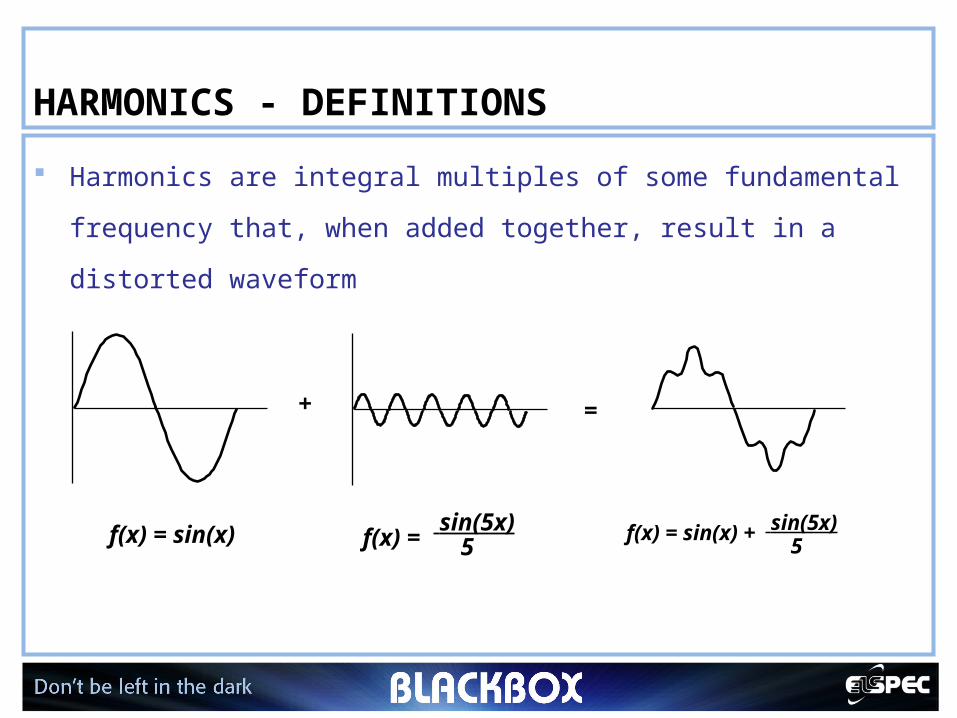
HARMONICS - DEFINITIONS
Harmonics are integral multiples of some fundamental
frequency that, when added together, result in a distorted
waveform
f(x) = sin(x) f(x) = sin(5x)
5
+
f(x) = sin(x) + sin(5x)5
=
7
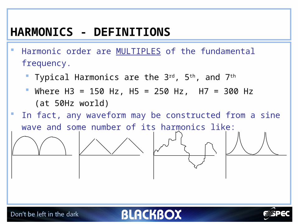
HARMONICS - DEFINITIONS Harmonic order are MULTIPLES of the fundamental frequency.
Typical Harmonics are the 3rd, 5th, and 7th
Where H3 = 150 Hz, H5 = 250 Hz, H7 = 300 Hz (at 50Hz world)
In fact, any waveform may be constructed from a sine wave and some number of its harmonics like:
8
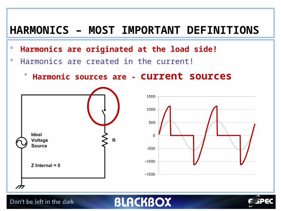
HARMONICS – MOST IMPORTANT DEFINITIONS
Harmonics are originated at the load side! Harmonics are created in the current!
Harmonic sources are - current sources
9
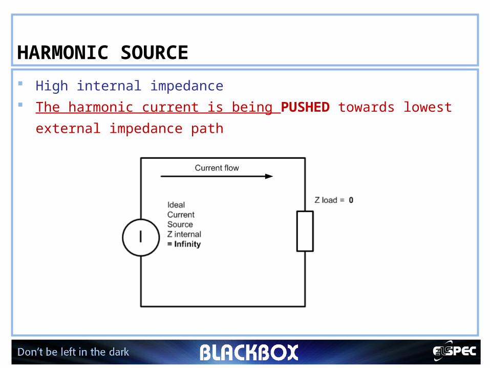
HARMONIC SOURCE
High internal impedance The harmonic current is being PUSHED towards lowest
external impedance path
10
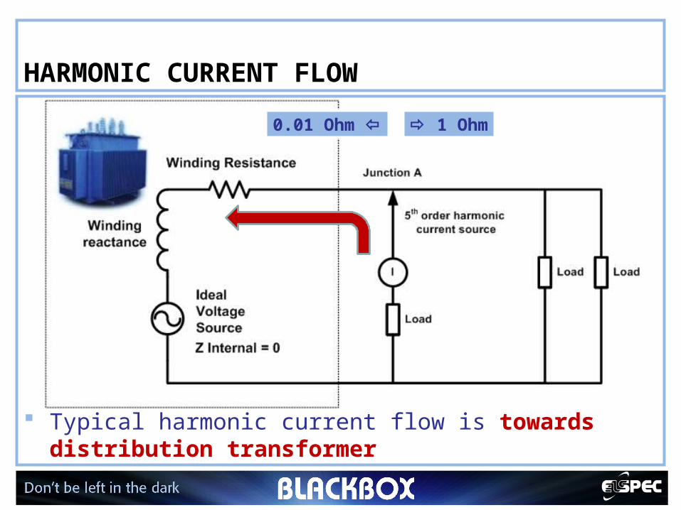
HARMONIC CURRENT FLOW
Typical harmonic current flow is towards distribution transformer
1 Ohm0.01 Ohm
11
HARMONICS – PROBLEMS?
I2r losses + “skin” effect
Voltage distortions
Iron-core losses
Cables/transformers overheat
Upstream pollutions
But, the real problems are yet to come
12
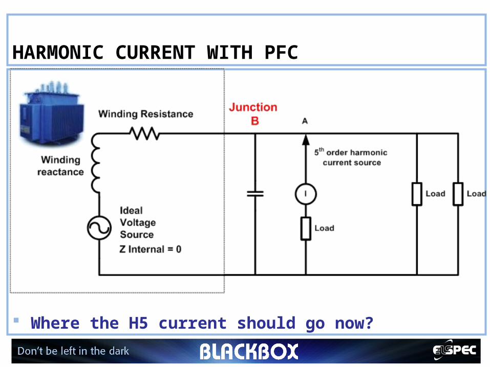
HARMONIC CURRENT WITH PFC
Where the H5 current should go now?
13
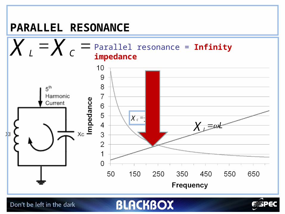
PARALLEL RESONANCE
C
1
X C
LX l
Parallel resonance = Infinity impedanceXX CL
14
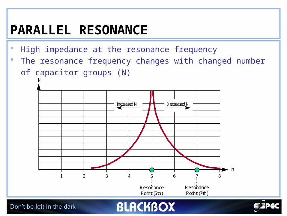
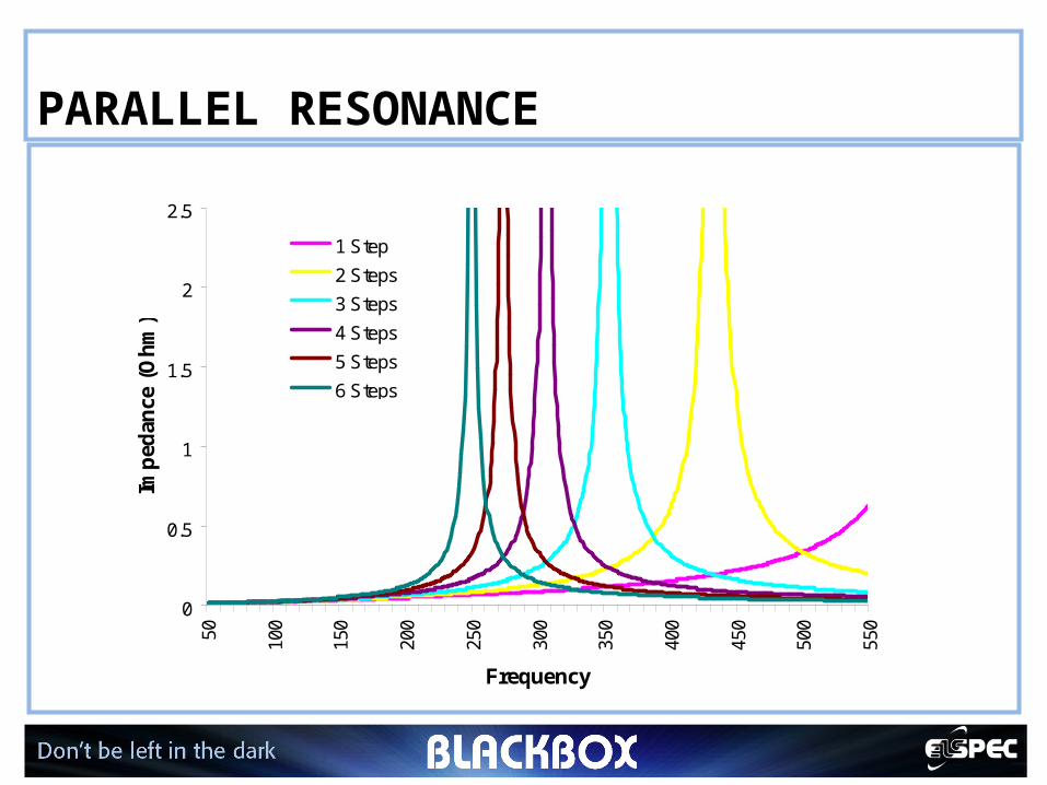
PARALLEL RESONANCE High impedance at the resonance frequency The resonance frequency changes with changed number of
capacitor groups (N)
1 2 3 4 6 7
ResonancePoint (7th)
85
ResonancePoint (5th)
k
n
Decreased NIncreased N
15
PARALLEL RESONANCE
0
0.5
1
1.5
2
2.550 100
150
200
250
300
350
400
450
500
550
Frequency
Imp
edan
ce (
Oh
m)
1 Step
2 Steps
3 Steps
4 Steps
5 Steps
6 Steps
16
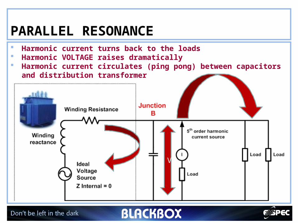
PARALLEL RESONANCE Harmonic current turns back to the loads Harmonic VOLTAGE raises dramatically Harmonic current circulates (ping pong) between capacitors
and distribution transformer
V
17
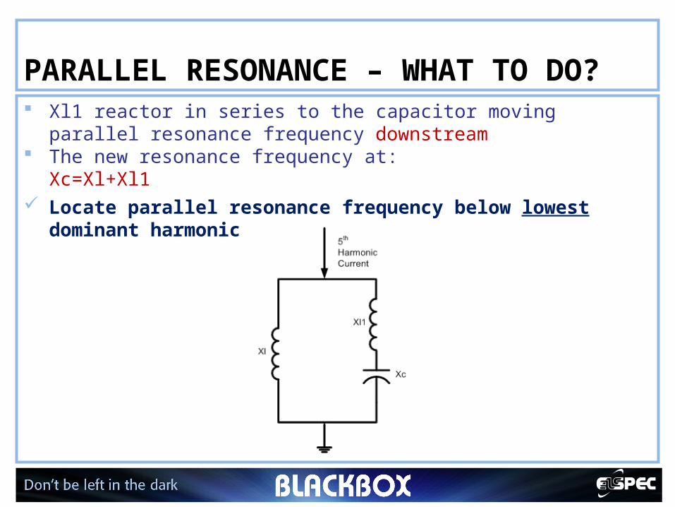
PARALLEL RESONANCE – WHAT TO DO? Xl1 reactor in series to the capacitor moving parallel resonance
frequency downstream The new resonance frequency at:
Xc=Xl+Xl1 Locate parallel resonance frequency below lowest
dominant harmonic
18
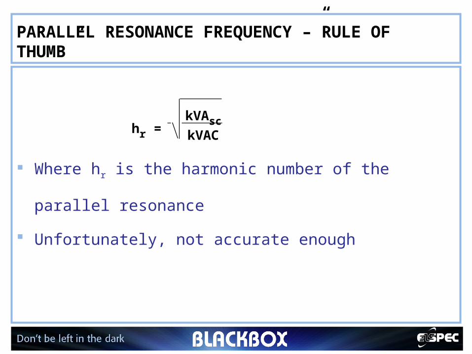
PARALLEL RESONANCE FREQUENCY –”RULE OF THUMB”
Where hr is the harmonic number of the parallel
resonance
Unfortunately, not accurate enough
hr = kVAsc
kVAC
19
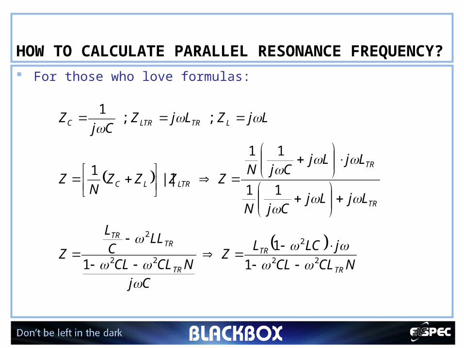
HOW TO CALCULATE PARALLEL RESONANCE FREQUENCY? For those who love formulas:
1
1
1
11
11
|| 1
; ; 1
22
2
22
2
NCLCL
jLCLZ
CjNCLCL
LLC
L
Z
LjLjCjN
LjLjCjN
ZZZZN
Z
LjZLjZCj
Z
TR
TR
TR
TRTR
TR
TR
LTRLC
LTRLTRC
20
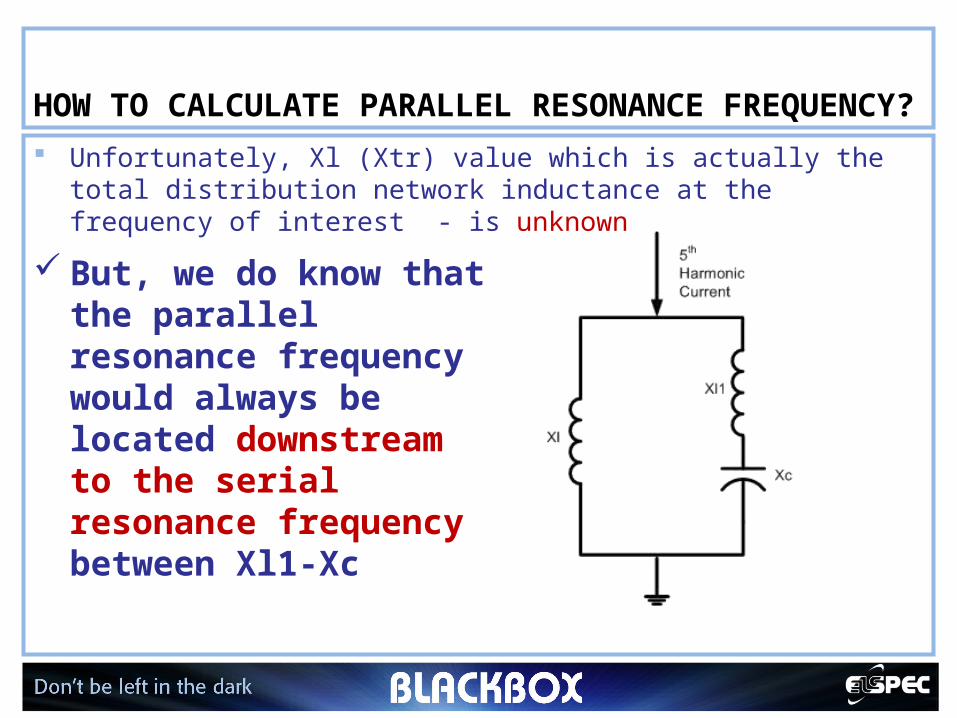
HOW TO CALCULATE PARALLEL RESONANCE FREQUENCY? Unfortunately, Xl (Xtr) value which is actually the total
distribution network inductance at the frequency of interest - is unknown
But, we do know that the parallel resonance frequency would always be located downstream to the serial resonance frequency between Xl1-Xc
21
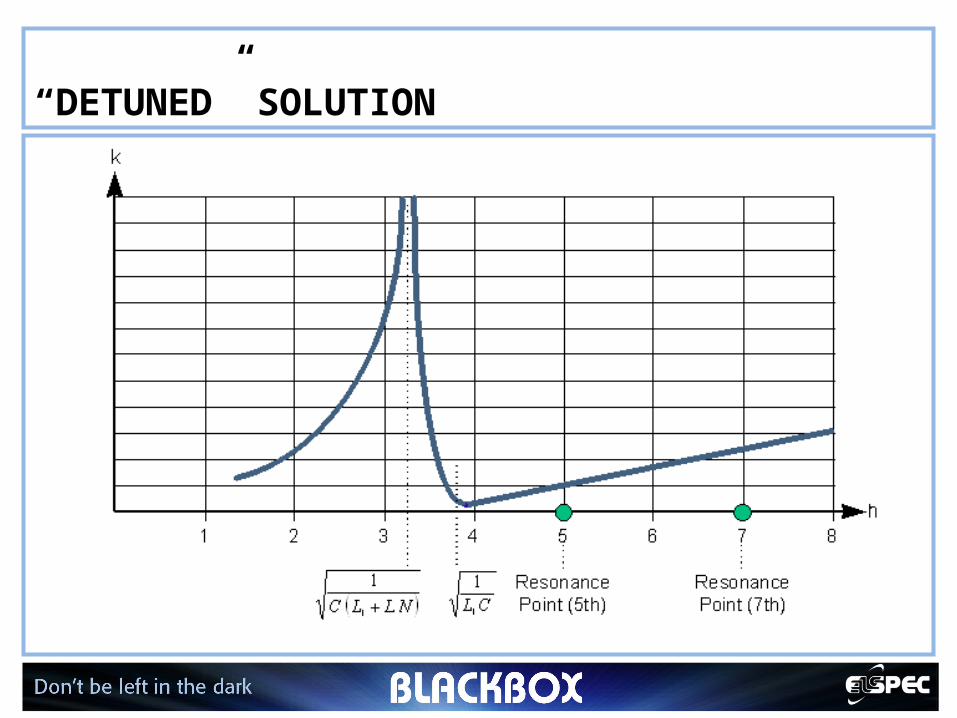
“DETUNED” SOLUTION
22
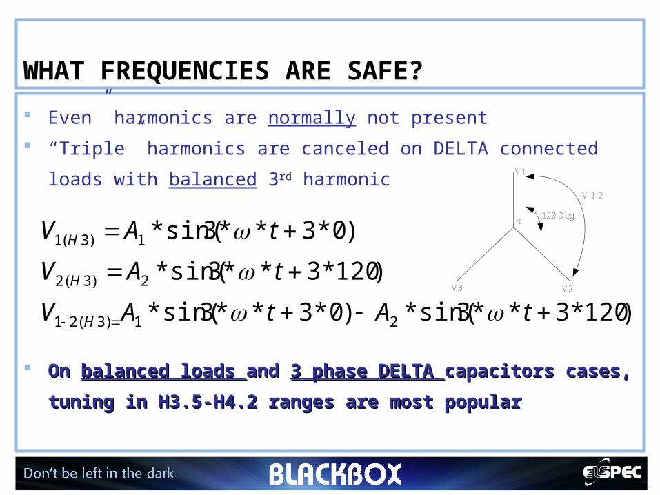
WHAT FREQUENCIES ARE SAFE?
Even” harmonics are normally not present
“Triple” harmonics are canceled on DELTA connected loads
with balanced 3rd harmonic
On On balanced loads balanced loads and and 3 phase DELTA 3 phase DELTA capacitors cases, capacitors cases,
tuning in H3.5-H4.2 ranges are most popular tuning in H3.5-H4.2 ranges are most popular
)120*3**3sin(*)0*3**3sin(*
)120*3**3sin(*
)0*3**3sin(*
21)3(21
2)3(2
1)3(1
tAtAV
tAV
tAV
H
H
H
V1
V2V3
N120 Deg.
V 1-2
23
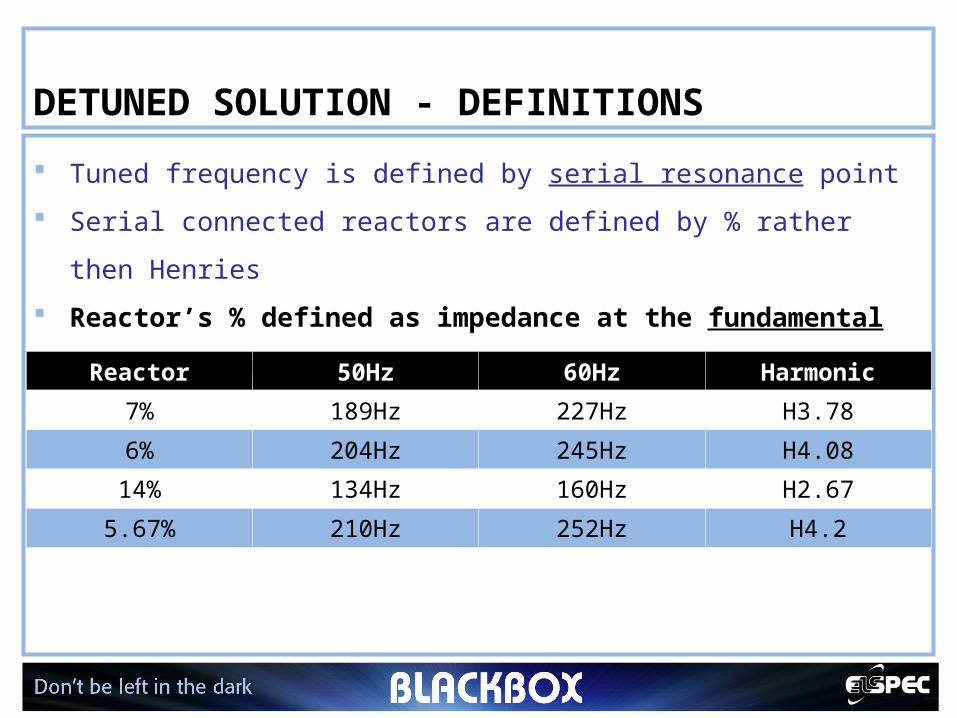
DETUNED SOLUTION - DEFINITIONS
Tuned frequency is defined by serial resonance point
Serial connected reactors are defined by % rather then Henries
Reactor’s % defined as impedance at the fundamental
frequency with respect to the capacitor’s impedance at
the same frequencyReactor 50Hz 60Hz Harmonic
7% 189Hz 227Hz H3.78
6% 204Hz 245Hz H4.08
14% 134Hz 160Hz H2.67
5.67% 210Hz 252Hz H4.2
24
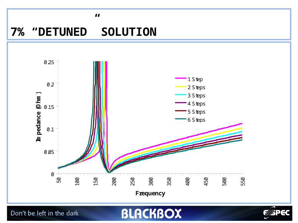
7% “DETUNED” SOLUTION
0
0.05
0.1
0.15
0.2
0.2550 100
150
200
250
300
350
400
450
500
550
Frequency
Imp
edan
ce (
Oh
m)
1 Step
2 Steps
3 Steps
4 Steps
5 Steps
6 Steps
25
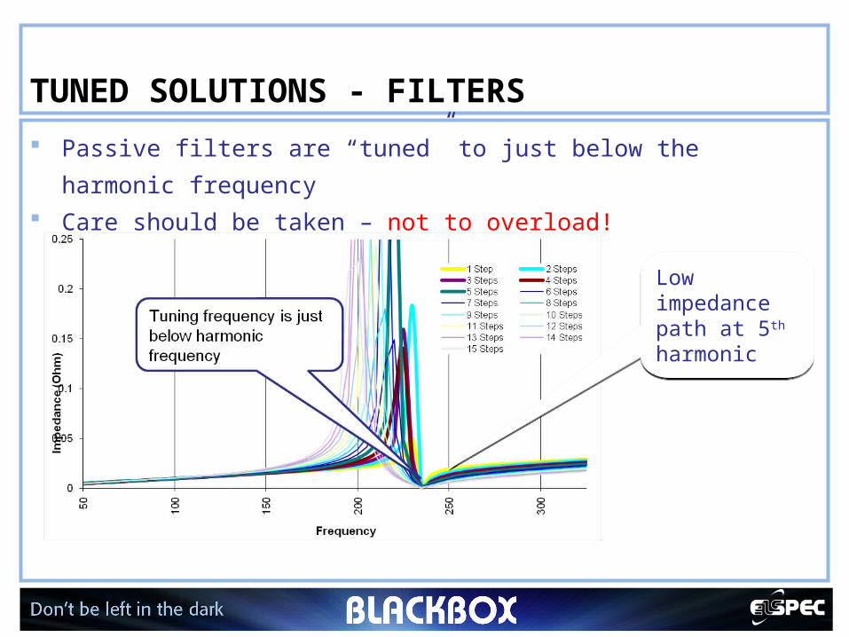
TUNED SOLUTIONS - FILTERS
Passive filters are “tuned” to just below the harmonic
frequency Care should be taken – not to overload!
Low impedance path at 5th harmonic
Low impedance path at 5th harmonic
26
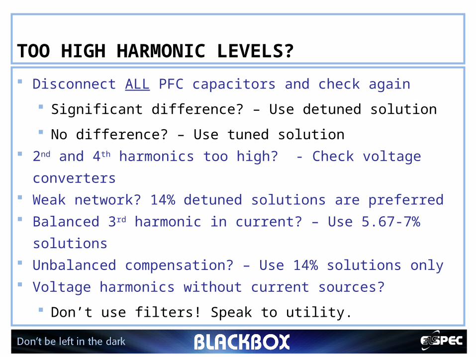
TOO HIGH HARMONIC LEVELS?
Disconnect ALL PFC capacitors and check again
Significant difference? – Use detuned solution
No difference? – Use tuned solution 2nd and 4th harmonics too high? - Check voltage
converters Weak network? 14% detuned solutions are preferred Balanced 3rd harmonic in current? – Use 5.67-7%
solutions Unbalanced compensation? – Use 14% solutions only Voltage harmonics without current sources?
Don’t use filters! Speak to utility.