Mass-Spring Sys + Harmonic Mass-Spring Sys + Harmonic Mass-Spring Sys + Harmonic

International Research Journal of Engineering and Technology (IRJET) e-ISSN: 2395-0056
Volume: 08 Issue: 03 | Mar 2021 www.irjet.net p-ISSN: 2395-0072
© 2021, IRJET | Impact Factor value: 7.529 | ISO 9001:2008 Certified Journal | Page 3119
Harmonic Analysis of Three Phase 3-Level and 5-Level CHB Multilevel
Inverter using SPWM Technique
Karishma Patel1, Gaurang Patel2
1M.E Student, Electrical Department, Mahatma Gandhi Institute of Technical education and Research center Navsari-396450, Gujarat, India
2Assistant Professor, Electrical Department, Mahatma Gandhi Institute of Technical education and Research center,Navsari-396450, Gujarat, India
----------------------------------------------------------------------***---------------------------------------------------------------------Abstract - Multilevel Inverter technology has emerged recently as a very important alternative in the area of high power, high voltage energy control. It came into picture and it has gained more attention in market for various applications like renewable energy systems, industrial motor drives, etc. It can generate stepped waveform by reducing harmonic distortion with increase in the number of voltage level. The main advantages of this multilevel inverter are that it generates very less harmonics. In this paper, one carrier based PWM technique is proposed i.e. level shifted scheme which can minimize the total harmonic distortion and enhances the output voltage. Level Shifted [LS] Scheme is applied to the Cascade H-bridge multilevel inverter and the complete analysis of THD three level to five levels is done.
Key Words: CHB multilevel inverter, 3-level CHB, 5-level CHB, level shifting SPWM, %THD
1. INTRODUCTION
The tremendous increase in energy demand led to call of high power converter technology to transmit the power with high accuracy. When dealing with high voltages, conventional inverters produce output voltages of low quality and high harmonic content which affects the equipment performance. So new power converter topologies were invented known as multilevel inverters and gained importance in industry applications because of high power ratings and better harmonic performance suitable for medium and high power applications. The output voltage of multilevel inverters is in form of stepped waveforms and obtained easily without use of transformers which decreases the cost of inverter. Improved quality of waveforms can be obtained by increasing number of steps in the output waveforms and the harmonic content also comes down[1]. Multilevel Inverters are classified into three topologies namely diode clamped, flying capacitor and cascaded type inverters. PWM is a technique in which width of gate pulses are controlled and used for various applications. Different types of PWM technique are proposed for multilevel inverters like sinusoidal pulse width modulation, selective harmonic elimination and space vector modulation. SPWM is considered as the best technique among other PWM methods because of various reasons like high power handling capacity, no temperature variation, easy to
implement and control. Here SPWM is used for modelling of three level and five level cascaded H-bridge inverter. The design and modelling of three levels and five levels CHB is done in MATLAB/SIMULINK.
1.1 MULTILEVEL CASCADED H- BRIDGE INVERTER
A. General Description
General blocks present in MLI have been represented in the diagram given in Fig. 1.
Fig. 1. Block diagram of multi-level inverter
Depending upon DC sources the CHB inverter has two types: symmetrical and asymmetrical topologies.[3] CHB inverter with equal DC voltage and CHB inverter with unequal DC voltage. By using CHB inverter with unequal DC voltage source, the number of voltage levels is increased without increasing the number of H-bridges. But there are more drawbacks in this case such as the voltage stress on each switch is different and hence losses in increases. In addition to this, switching pattern design become more complex therefore this topology have some limited applications. Therefore we are using CHB inverters with equal DC voltage sources.
Fig. 2. H-bridge cell of CHB Multilevel Inverter
International Research Journal of Engineering and Technology (IRJET) e-ISSN: 2395-0056
Volume: 08 Issue: 03 | Mar 2021 www.irjet.net p-ISSN: 2395-0072
© 2021, IRJET | Impact Factor value: 7.529 | ISO 9001:2008 Certified Journal | Page 3120
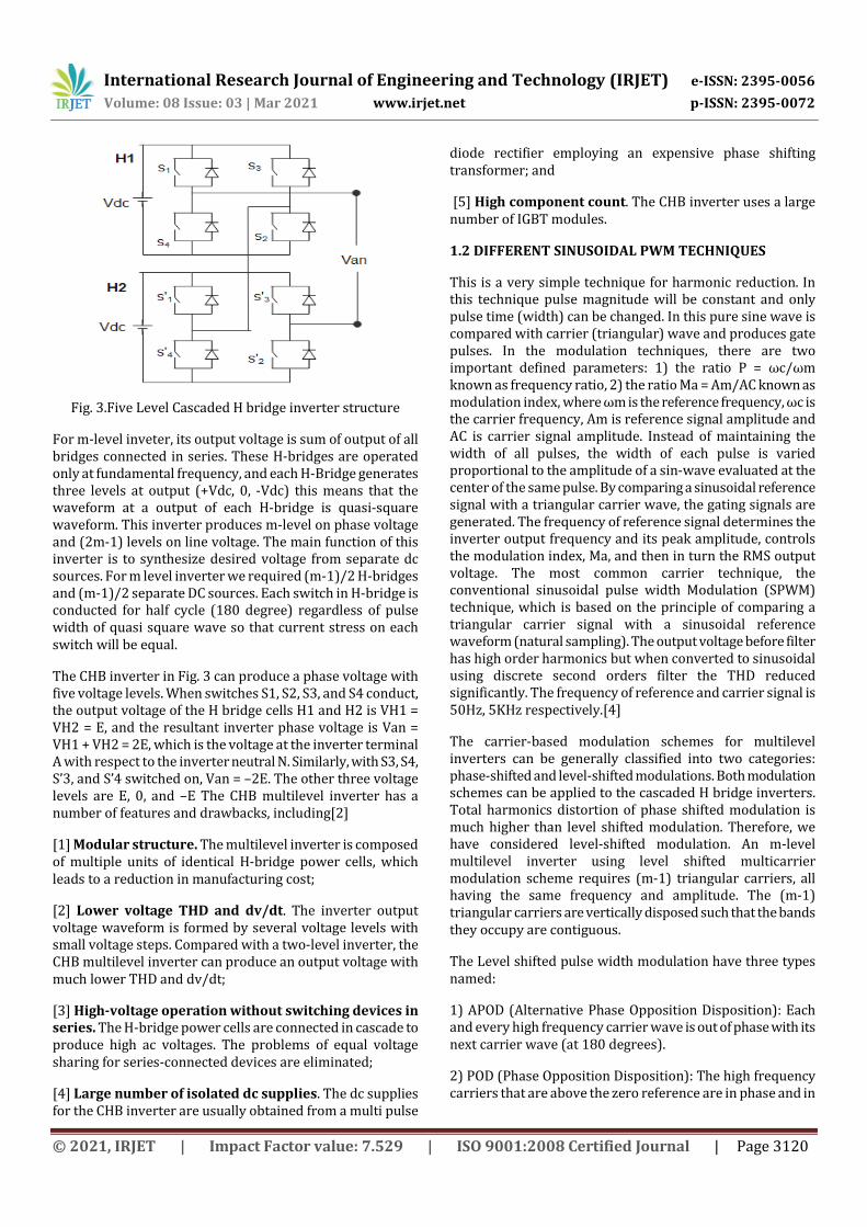
Fig. 3.Five Level Cascaded H bridge inverter structure
For m-level inveter, its output voltage is sum of output of all bridges connected in series. These H-bridges are operated only at fundamental frequency, and each H-Bridge generates three levels at output (+Vdc, 0, -Vdc) this means that the waveform at a output of each H-bridge is quasi-square waveform. This inverter produces m-level on phase voltage and (2m-1) levels on line voltage. The main function of this inverter is to synthesize desired voltage from separate dc sources. For m level inverter we required (m-1)/2 H-bridges and (m-1)/2 separate DC sources. Each switch in H-bridge is conducted for half cycle (180 degree) regardless of pulse width of quasi square wave so that current stress on each switch will be equal.
The CHB inverter in Fig. 3 can produce a phase voltage with five voltage levels. When switches S1, S2, S3, and S4 conduct, the output voltage of the H bridge cells H1 and H2 is VH1 = VH2 = E, and the resultant inverter phase voltage is Van = VH1 + VH2 = 2E, which is the voltage at the inverter terminal A with respect to the inverter neutral N. Similarly, with S3, S4, S’3, and S’4 switched on, Van = –2E. The other three voltage levels are E, 0, and –E The CHB multilevel inverter has a number of features and drawbacks, including[2]
[1] Modular structure. The multilevel inverter is composed of multiple units of identical H-bridge power cells, which leads to a reduction in manufacturing cost;
[2] Lower voltage THD and dv/dt. The inverter output voltage waveform is formed by several voltage levels with small voltage steps. Compared with a two-level inverter, the CHB multilevel inverter can produce an output voltage with much lower THD and dv/dt;
[3] High-voltage operation without switching devices in series. The H-bridge power cells are connected in cascade to produce high ac voltages. The problems of equal voltage sharing for series-connected devices are eliminated;
[4] Large number of isolated dc supplies. The dc supplies for the CHB inverter are usually obtained from a multi pulse
diode rectifier employing an expensive phase shifting transformer; and
[5] High component count. The CHB inverter uses a large number of IGBT modules.
1.2 DIFFERENT SINUSOIDAL PWM TECHNIQUES
This is a very simple technique for harmonic reduction. In this technique pulse magnitude will be constant and only pulse time (width) can be changed. In this pure sine wave is compared with carrier (triangular) wave and produces gate pulses. In the modulation techniques, there are two important defined parameters: 1) the ratio P = ωc/ωm known as frequency ratio, 2) the ratio Ma = Am/AC known as modulation index, where ωm is the reference frequency, ωc is the carrier frequency, Am is reference signal amplitude and AC is carrier signal amplitude. Instead of maintaining the width of all pulses, the width of each pulse is varied proportional to the amplitude of a sin-wave evaluated at the center of the same pulse. By comparing a sinusoidal reference signal with a triangular carrier wave, the gating signals are generated. The frequency of reference signal determines the inverter output frequency and its peak amplitude, controls the modulation index, Ma, and then in turn the RMS output voltage. The most common carrier technique, the conventional sinusoidal pulse width Modulation (SPWM) technique, which is based on the principle of comparing a triangular carrier signal with a sinusoidal reference waveform (natural sampling). The output voltage before filter has high order harmonics but when converted to sinusoidal using discrete second orders filter the THD reduced significantly. The frequency of reference and carrier signal is 50Hz, 5KHz respectively.[4]
The carrier-based modulation schemes for multilevel inverters can be generally classified into two categories: phase-shifted and level-shifted modulations. Both modulation schemes can be applied to the cascaded H bridge inverters. Total harmonics distortion of phase shifted modulation is much higher than level shifted modulation. Therefore, we have considered level-shifted modulation. An m-level multilevel inverter using level shifted multicarrier modulation scheme requires (m-1) triangular carriers, all having the same frequency and amplitude. The (m-1) triangular carriers are vertically disposed such that the bands they occupy are contiguous.
The Level shifted pulse width modulation have three types named:
1) APOD (Alternative Phase Opposition Disposition): Each and every high frequency carrier wave is out of phase with its next carrier wave (at 180 degrees).
2) POD (Phase Opposition Disposition): The high frequency carriers that are above the zero reference are in phase and in

International Research Journal of Engineering and Technology (IRJET) e-ISSN: 2395-0056
Volume: 08 Issue: 03 | Mar 2021 www.irjet.net p-ISSN: 2395-0072
© 2021, IRJET | Impact Factor value: 7.529 | ISO 9001:2008 Certified Journal | Page 3121
180 degrees out of phase with carrier waves which are below the zero reference.
3) PD (Phase Disposition): All high frequency carrier waves are in phase.
2. SIMULATION AND RESULTS
The cascaded three phase 5-level inverter are modeled in MATLAB/SIMULINK. The switching signal for each and every switch in inverter is generated from e level shift SPWM and analyzed by FFT analysis.
Table -1: Parameters for simulation of MLI
Parameters Values
DC input voltage 400V
Switching frequency 4kHz
Rated output frequency 50Hz
Fig. 4. Simulation model for three-phase 3level CHB
(a)
(b)
Fig.5 Using SPWM (a) comparison of carrier and modulating wave(b)Gate pulse of upper and lower switch
waveforms
Fig.6 Phase Voltage Waveform
Fig.7 Line Voltage Waveform
Fig. 8. Simulation model for three-phase 5 level CHB
(a)

International Research Journal of Engineering and Technology (IRJET) e-ISSN: 2395-0056
Volume: 08 Issue: 03 | Mar 2021 www.irjet.net p-ISSN: 2395-0072
© 2021, IRJET | Impact Factor value: 7.529 | ISO 9001:2008 Certified Journal | Page 3122
(b)
Fig.9 Using SPWM (a) comparison of carrier and modulating wave, (b) Gate pulse of upper and lower switch
waveforms
Fig.10 Phase Voltage Waveform
Fig.11 Line Voltage Waveform
Fig.12 FFT analysis of 3 level CHB inverter
Fig.13 FFT analysis of 5 level CHB inverter
3. CONCLUSION
Multilevel inverter are very suitable for PV generation. H
bridge cell with SPWM control is very promising solution not
only for having medium and high voltage but for improving
the quality of the voltage i.e. reduction of THD. In this paper
The 3 level and 5 level inverter is simulated using matlab
and the results are verified. In waveform obtained at the
output of 5 level inverter has more number of steps and THD
obtained is less compared to 3 level CHB inverter.
REFERENCES
[1] Muhammad H. Rashid, ”Power electronic circuits, devices and applications”, 3rd edition, Pearson Education Inc.,chapter 9, pp 406-422 2003.
[2] B.Wu, High-Power Converters and AC Drives. Piscataway, NJ: IEEE Press, 2006.
[3] Dr. Sachin S. Bharatk, Mr. Raju R. Bhoyar, Mr. Sarang A. Khadtare “Analysis of three phase cascaded H-bridge multilevel inverter for symmetrical & asymmetrical configuration.” IEEE-2014.
[4] Mr.Darshan Patel, Dr.R.Saravanakumar, Dr.K.K.Ray, Mr.RameshR, Power “A Review of Various Carrier based PWM Methods for Multilevel Inverter” IEEE Conference publications Page(s): 1 – 6, 2011.
[5] A. Nabe, I. Takahashi and H. Akagi. “A new neutral point clamped PWM inverter.” IEEE Trans.Ind. Applicat. vol, 1A-17, pp 518-523, sep/oct 1981.
[6] Jose Rodriguez, Jih-sheng Lai and Fang ZhengPeng. “Multilevel inverters : A survey of topologies, controls, and applications”. IEEE Trans.Ind.Electronics. Vol-49 no.4 pp 724-738, Aug.2002.
[7] X. Yun, Y. Zou, X. Liu, and Y. He, “A novel composite cascade multi level converter,” in Proc.. 33rd IEEE IECON, pp. 1799-1804, 2007.
[8] K.Srinivas, K. Ramesh babu, CH. Rambabu3, “A New Multilevel Topology For Induction Motor Drive”. Volume 2, Issue 12, December, IJETAE 2012.

International Research Journal of Engineering and Technology (IRJET) e-ISSN: 2395-0056
Volume: 08 Issue: 03 | Mar 2021 www.irjet.net p-ISSN: 2395-0072
© 2021, IRJET | Impact Factor value: 7.529 | ISO 9001:2008 Certified Journal | Page 3123
[9] Ville Naumanen “Multilevel converter modulation: implementation and analysis” Lappeenranta,,ISBN 978-952-214-933-6, ISBN 978-952-214-934-3 , ISSN 1456-4491,2010.
[10] M. Malinowski, K. Gopakumar, J. Rodriguez, and M. A. Perez, "A survey on cascaded multilevel inverters, " IEEE Trans. Ind. Electron., vol. 57, no. 7, pp. 2197- 2206, 20l0.