Harley Diagnostic Touble Codes
40
2004 Softail: Instruments 2-1 HOME CHECKING FOR DIAGNOSTIC TROUBLE CODES 2.1 CHECK ENGINE LAMP To diagnose electronic control module (ECM) or ignition con- trol module (ICM) system problems, start by observing the behavior of the check engine lamp. NOTES ● See Figure 2-1. “Key ON” means that the ignition key is turned to ON and the engine stop switch is set to RUN (although the engine is not running). ● When the ignition switch is turned ON, the check engine lamp will illuminate for approximately four seconds and then turn off. ● If the check engine lamp is not illuminated at Key ON. See 2.2 INITIAL DIAGNOSTIC CHECK: SPEEDOME- TER. ● If the check engine lamp comes on late (after 20 sec- onds). See 2.2 INITIAL DIAGNOSTIC CHECK: SPEED- OMETER. ● If the check engine lamp fails to turn OFF after the initial four second period. See 2.2 INITIAL DIAGNOSTIC CHECK: SPEEDOMETER. 1. See Figure 2-3. After lamp turns off after being illumi- nated for the first four second period, one of three situa- tions may occur. a. The lamp remains off. This indicates there are no current fault conditions or stored diagnostic trouble codes currently detected by the ignition control mod- ule (ICM) or electronic control module (ECM). b. The lamp stays off for only four seconds and then comes back on for an eight second period. This indi- cates an diagnostic trouble code is stored, but no current diagnostic trouble code exists. c. If the lamp remains on beyond the eight second period, then a current diagnostic trouble code exists. 2. See CODE TYPES which follows for a complete descrip- tion of diagnostic trouble code formats. NOTE Some diagnostic trouble codes can only be fully diagnosed during actuation. For example, a problem with the ignition coil will be considered a current fault even after the problem is corrected, since the ECM/ICM will not know of its resolution until after the coil is exercised by vehicle start sequence. In this manner, there may sometimes be a false indication of the current diagnostic trouble code. Figure 2-1. Ignition Switch Figure 2-2. Check Engine Lamp 1. Lock position 2. Unlock position 3. Open switch cover 1 s0270x8x 2 3 Ignition Accessory OFF d0715x8x 5
-
Upload
leandro-lima -
Category
Documents
-
view
101 -
download
9
Transcript of Harley Diagnostic Touble Codes

HOME
5
CHECKING FOR DIAGNOSTIC TROUBLE CODES 2.1
CHECK ENGINE LAMP
To diagnose electronic control module (ECM) or ignition con-trol module (ICM) system problems, start by observing thebehavior of the check engine lamp.
NOTES● See Figure 2-1. “Key ON” means that the ignition key is
turned to ON and the engine stop switch is set to RUN(although the engine is not running).
● When the ignition switch is turned ON, the check enginelamp will illuminate for approximately four seconds andthen turn off.
● If the check engine lamp is not illuminated at Key ON.See 2.2 INITIAL DIAGNOSTIC CHECK: SPEEDOME-TER.
● If the check engine lamp comes on late (after 20 sec-onds). See 2.2 INITIAL DIAGNOSTIC CHECK: SPEED-OMETER.
● If the check engine lamp fails to turn OFF after the initialfour second period. See 2.2 INITIAL DIAGNOSTICCHECK: SPEEDOMETER.
1. See Figure 2-3. After lamp turns off after being illumi-nated for the first four second period, one of three situa-tions may occur.
a. The lamp remains off. This indicates there are nocurrent fault conditions or stored diagnostic troublecodes currently detected by the ignition control mod-ule (ICM) or electronic control module (ECM).
b. The lamp stays off for only four seconds and thencomes back on for an eight second period. This indi-cates an diagnostic trouble code is stored, but nocurrent diagnostic trouble code exists.
c. If the lamp remains on beyond the eight secondperiod, then a current diagnostic trouble code exists.
2. See CODE TYPES which follows for a complete descrip-tion of diagnostic trouble code formats.
NOTESome diagnostic trouble codes can only be fully diagnosedduring actuation. For example, a problem with the ignition coilwill be considered a current fault even after the problem iscorrected, since the ECM/ICM will not know of its resolutionuntil after the coil is exercised by vehicle start sequence. Inthis manner, there may sometimes be a false indication of thecurrent diagnostic trouble code.
Figure 2-1. Ignition Switch
Figure 2-2. Check Engine Lamp
1. Lock position2. Unlock position3. Open switch cover
1s0270x8x
2
3
Ignition Accessory
OFF
d0715x8x
2004 Softail: Instruments 2-1

HOME
SECURITY LAMP
To diagnose TSM/TSSM system problems, start by observingthe behavior of the security lamp.
NOTES
● To provide an indication of TSM/TSSM diagnostic codes,the security lamp is enabled on all models.
● See Figure 2-1. “Key ON” means that the ignition key isturned to ON and the engine stop switch is set to RUN(although the engine is not running).
● When the ignition switch is turned ON, the check enginelamp will illuminate for approximately four seconds andthen turn off.
● If the check engine lamp is not illuminated at Key ON,see 2.2 INITIAL DIAGNOSTIC CHECK: SPEEDOME-TER.
● If the check engine lamp comes on late (after 20 sec-onds), see 2.2 INITIAL DIAGNOSTIC CHECK: SPEED-OMETER.
● If the check engine lamp fails to turn OFF after the initialfour second period, see 2.2 INITIAL DIAGNOSTICCHECK: SPEEDOMETER.
1. See Figure 2-3. After lamp turns off after being illumi-nated for the first four second period, one of three situa-tions may occur.
a. The lamp remains off. This indicates there are nocurrent fault conditions or stored diagnostic troublecodes currently detected by the ignition control mod-ule (ICM) or electronic control module (ECM).
b. The lamp stays off for only four seconds and thencomes back on for an eight second period. This indi-cates an diagnostic trouble code is stored, but nocurrent diagnostic trouble code exists.
c. If the lamp remains on beyond the eight secondperiod, then a current diagnostic trouble code exists.
2. See CODE TYPES which follows for a complete descrip-tion of diagnostic trouble code formats.
NOTESome diagnostic trouble codes can only be fully diagnosedduring actuation. For example, a problem with the turn signalswill be considered a current fault even after the problem iscorrected, since the TSM/TSSM will not know of its resolutionuntil after the turn signals are activated. In this manner, theremay sometimes be a false indication of a diagnostic troublecode.
Figure 2-3. Check Engine and Security Lamp Operation
ON
OFF
ON
OFF
ON
OFF
Key ON
Key ON
A
B
C
Lamp ON 8 Seconds:Only Historic DTCs Exist
Lamp OFF: No Current or Historic DTCs
Lamp Remains ON: Current DTC *
Lamp OFF
* Historic DTCs May Also Exist
4 Sec.
4 Sec.
8 Sec.
Key ON
4 Sec.
4 Sec.
4 Sec.
2-2 2004 Softail: Instruments

HOME
CODE TYPES
There are two types of diagnostic trouble codes (DTCs): cur-rent and historic. If a DTC is stored, it can be read usingspeedometer self diagnostics. See 2.3 SPEEDOMETERSELF DIAGNOSTICS.
NOTETo differentiate between current and historic diagnostic trou-ble codes a computer based diagnostic package called DIGI-TAL TECHNICIAN (Part No. HD-44750) must be employed.
All DTCs reside in the memory of the ECM/ICM, TSM/TSSMor speedometer until the DTC is cleared by use of the speed-ometer self diagnostics. See 2.3 SPEEDOMETER SELFDIAGNOSTICS.
A DTC is also cleared after a total of 50 trips has elapsed. Atrip consists of a start and run cycle. After the 50 trip retentionperiod, the DTC is automatically erased from memory provid-ing that no subsequent faults of the same type are detected inthat period.
CurrentCurrent DTCs are those which presently disrupt motorcycleoperation. See the appropriate flow charts for solutions.
HistoricIf a particular problem happens to resolve itself, the activestatus problem is dropped and it becomes a historic faultrather than a current fault.
Historic DTCs can only be retrieved using a computer baseddiagnostic package called DIGITAL TECHNICIAN (Part No.HD-44750).
Historic DTCs are stored for a length of time to assist in thediagnosis of intermittent faults. The check engine lamp willnot indicate the existence of only historic DTCs.
It is important to note that historic DTCs may also be presentwhenever the system indicates the existence of a currentfault. See MULTIPLE DIAGNOSTIC TROUBLE CODES ifmultiple DTCs are found.
Diagnostic charts are designed for use with current DTCs andas a result they frequently suggest part replacement. Whendiagnosing a historic DTC the charts can be helpful butshould not lead to part replacement without verification thepart is faulty.
RETRIEVING DIAGNOSTIC TROU-BLE CODES
The speedometer provides two levels of diagnostics.
● The most sophisticated mode employs a computerbased diagnostic package called DIGITAL TECHNICIAN(Part No. HD-44750).
● The second mode requires using the speedometer selfdiagnostics. See 2.3 SPEEDOMETER SELF DIAGNOS-TICS.
MULTIPLE DIAGNOSTIC TROUBLE CODES
While it is possible for more than one fault to occur and setmore than one DTC, there are several conditions which mayresult in one fault setting multiple DTCs:
Serial data DTCs (U1016, U1064, U1097, U1255, U1300 andU1301) may be accompanied by other DTCs. Always correctthe serial data DTCs before resolving the other DTCs.
For proper resolution to multiple DTCs refer to diagnosticcode priority chart page 2-6, Table 2-2.
2004 Softail: Instruments 2-3

HOME
INITIAL DIAGNOSTIC CHECK: SPEEDOMETER 2.2
GENERAL
● Constant power is supplied to the speedometer throughterminal 5 of connector [39]. The speedometer turns onwhen power is applied to terminal 1 of connector [39].The speedometer goes through an initializationsequence every time power is removed and re-applied toterminal 6. The visible part of this sequence is the checkengine lamp (in “run” mode), security lamp (models withsecurity only), backlighting, odometer and fuel level (EFIonly). Upon key ON, the check engine lamp and securitylamp will illuminate for 4 seconds and then (if parametersare normal) go out.
● To locate faulty circuits or other system problems, followthe diagnostic flow charts and tests in this section. For asystematic approach, always begin with INITIAL DIAG-NOSTICS which follows. Read the general informationand then work your way through the flow chart box bybox.
● Loss of power on any of the four power inputs willchange speedometer behavior. Refer to Table 2-1.Speedometer Function Chart-Loss Of Input.
Diagnostic Notes
If a numbered circle appears adjacent to a flow chart box,then more information is offered in the diagnostic notes. Manydiagnostic notes contain supplemental information, descrip-tions of various diagnostic tools or references to other partsof the manual where information on the location and removalof components may be obtained.
Circuit Diagram/Wire HarnessConnector Table
When working through a flow chart, refer to the illustrations,the associated circuit diagram and the wire harness connec-tor table as necessary. The wire harness connector table foreach circuit diagram identifies the connector number, descrip-tion, type and general location.
In order to perform most diagnostic routines, a Breakout Boxand a digital volt/ohmmeter (DVOM) are required. See 2.5BREAKOUT BOX: SPEEDOMETER.
To perform the circuit checks with any degree of efficiency, afamiliarity with the various wire connectors is also necessary.
Job/Time Code Values
Dealership technicians filing warranty claims should use thejob/time code values printed in bold text underneath theappropriate repair.
Reprogramming ICM/ECMDiagnostic charts frequently suggest ECM/ICM replacement.In the event an ignition control module (ICM) or electroniccontrol module (ECM) needs to be replaced, it must be repro-grammed using a computer based diagnostic package calledDIGITAL TECHNICIAN (Part No. HD-44750). See yourdealer. Password learn procedure must also be performed.See 3.23 PASSWORD LEARN.
Figure 2-4. Fuse Block Location
Figure 2-5. Relay/Fuse Panel (top view)
1
7778
2
3
4
1. Fuse block2. Starter relay3. System relay4. Spare fuses
so444a0x
1
2
3
4
5
6
8
7
9
10 11
12
14
1. ECM* 15 Amp2. Fuel Pump* 15 Amp3. Headlamp4. P&A (2 Amp max)5. Battery6. Accessories7. Instruments8. Ignition
9. Lights10. Start Relay11. System Relay (EFI)12. Spare 15 Amp13. Spare 15 Amp14. Empty
*EFI Fuses
13
2-4 2004 Softail: Instruments
HOME
INITIAL DIAGNOSTICS
Diagnostic Tips● If speedometer reads “BUS Er” with the ignition key
turned ON (engine stop switch at RUN with the engineoff), check data bus for an open or short to ground.between data link connector [91A] terminal 3 and ICMconnector [10B] terminal 12 (carbureted models), ECMconnector [78B] terminal 5 (EFI models), TSSM connec-tor [30B] terminal 3 or speedometer connector [39B] ter-minal 2.
● Check for an open diagnostic test terminal between diag-nostic link connector [91A] terminal 3 and TSM/TSSMconnector [30B] terminal 3. With ignition key turned ON,serial data bus voltage should be typically 0.6-0.8 volts.The range of acceptable voltage is greater than 0 andless than 7.0 volts.
● To identify intermittents, wiggle instrument and/or vehicleharness while performing steps in the Diagnostic Checkcharts.
2004 Softail: Instruments 2-5

HOME
Diagnostic NotesThe reference numbers below correlate with the circled num-bers on the diagnostic check flow charts. See page 2-9.
1. Connect BREAKOUT BOX (Part No. HD-42682) andINSTRUMENT HARNESS ADAPTERS (Part No. HD-46601) between wire harness and speedometer. See 2.5BREAKOUT BOX: SPEEDOMETER.
All speedometer diagnostic codes are listed on page 2-6 inTable 2-2.
Other Diagnostic Trouble Codes (DTCs)See 3.9 INITIAL DIAGNOSTIC CHECK: TSM/TSSM for anycodes related to the turn signal module (TSM) or turn signalsecurity module (TSSM).
See 4.4 INITIAL DIAGNOSTIC CHECK: ICM for any codesrelated to the ignition control module (ICM).
See 5.5 INITIAL DIAGNOSTIC CHECK: EFI for any codesrelated to the electronic control module (ECM).
Table 2-1. Speedometer Function Chart-Loss Of Input
Terminal 5 (Constant)
Terminal 1 (IGN) Terminal 6 (ACC) Terminal 7 (GRD)Terminal 8 and 11
(Reset Switch)
● Security lamp glows dimly dur-ing 4-second bulb check
● Will not “wow”
● Turn signals still functional
● Speedometer will indicate vehicle speed (zero)
● Tachometer unaffected
● Security lamp still func-tional
● Check engine lamp and battery lamp non-func-tional
● Diagnostics absent
● Speedometer will be non-func-tional in acces-sory and ignition modes
● Security lamp still performs 4-second bulb check in ignition mode
● Speedometer com-pletely non-func-tional
● Diagnostics absent
● No reset switch function
● Will not “wow”
Table 2-2. Speedometer Diagnostic Trouble Codes (DTC) Priority Chart
DTC RANKING FAULT CONDITION SOLUTION
“BUS Er” 1 Serial data bus shorted low/open/high 2.14 DTC U1300, U1301 or “BUS ER”
U1300 2 Serial data bus shorted low2.14 DTC U1300, U1301 or “BUS ER”
U1301 3 Serial data bus shorted high2.14 DTC U1300, U1301 or “BUS ER”
U1016 4 Loss of ECM serial data 2.12 DTC U1016, U1255
U1064 5 Loss of TSM/TSSM serial data 2.13 DTC U1064, U1255
U1255 6Missing response from other module (TSM/TSSM and/or ICM/ECM) at startup
2.13 DTC U1064, U1255
B1007 7 Ignition line overvoltage 2.10 DTC B1006, B1007
B1006 8 Accessory line overvoltage 2.10 DTC B1006, B1007
B1008 9 Reset switch closed 2.11 DTC B1008
B1004 10 Fuel level sending unit low 2.9 DTC B1004, B1005
B1005 11 Fuel level sending unit high/open 2.9 DTC B1004, B1005
2-6 2004 Softail: Instruments

HOME
Figure 2-6. Diagnostic Check: EFI Models
3
1
2
4
51
321 654 987 121110321 654 987 121110321 654 987 121110
321 654 987 121110
d0700c8x
ECM
Data linkconnector
TSM/TSSM
[30B]
[30A]
[91A]
BK
LtGN/V
[78B]
[78A]
Speedometer
12VBattery
O
BK
Ser
ial d
ata
[39B]
[39A]
LtG
N/R
Fla
sh p
in
BN/GY
12Vinstrument
12VIgnition
GY
LtG
N/V
O/W
12VAccessory
LtG
N/V
LtG
N/V
BN
/GY
G
Y BK
Table 2-3. Wire Harness Connectors in Figure 2-6.
NO. DESCRIPTION TYPE LOCATION
[30] turn signal/security module 12-place Deutsch electrical panel behind fender extension
[39] speedometer 12-place Packard back of speedometer
[78]electronic control module (ECM):EFI models
36-place Packard under seat
[91] data link connector 4-place Deutsch under seat
2004 Softail: Instruments 2-7

HOME
Figure 2-7. Diagnostic Check: Carbureted Models
12
3
1
2
4
321 654 987 121110321 654 987 121110321 654 987 121110
321 654 987 121110
ICM
Data linkconnector
TSM/TSSM
LtG
N/V 12V
ignition
GY
[30B]
[30A]
[91A]
LtG
N/V
BK
LtGN/V
LtGN/V
[39B]
[39A]
[10B]
[10A]
Speedometer
12VBattery
BK
Ser
ial d
ata
d0721c8x
BN/GY
O/W
12Vinstrument
O
12VAccessory
BK
BN
/GY
G
Y
Table 2-4. Wire Harness Connectors in Figure 2-7.
NO. DESCRIPTION TYPE LOCATION
[10]ignition control module (ICM): car-bureted models
12-place Deutsch under seat
[30] turn signal/security module 12-place Deutsch electrical panel behind fender extension
[39] speedometer 12-place Packard back of speedometer
[91] data link connector 4-place Deutsch under seat
2-8 2004 Softail: Instruments

HOME
Diagnostic Check (Part 1 of 3)
NO
Check for continuity to ground on terminal 7 of speedometer. Wiggle harness during con-
tinuity check. Continuity present?
YES NO
YES NO
Check for battery voltage at terminal 5 of speedometer
while wiggling harness. Bat-tery voltage continuously
present?
1
Locate and repair open between terminal 5 and
battery fuse.
Locate and repair open between terminal 7
and ground.
YES.Starts and
runs.
For carbureted models, see 4.10 STARTS, THEN STALLS.
For EFI models, see 5.12 STARTS, THEN STALLS.
See 1.2 STARTING SYSTEM DIAGNOSIS.
YES.Starts, then
stalls.
NO.Cranks, but will not start.
NO. Engine will not
crank.
Does enginestart?
For carbureted models, see 4.9 ENGINE CRANKS, BUT WILL NOT START. For EFI models, see 5.10 ENGINE CRANKS,
BUT WILL NOT START.
YES
Check for diagnostic trou-ble codes (DTCs). See 2.3
SPEEDOMETER SELF DIAGNOSTICSDTCs found?
Refer to applicable DTC priority chart. All DTCs are listed on page 2-6 in Table 2-2.
DTCs are listed by priority.
STOP
Go to Diagnostic Check (Part 2 of 3).
NO
Replace speedometer. Replace speedometer reset switch.
NOYES
YES
With ignition switch OFF, press and release odometer reset switch. Does
odometer display appear?
With connector [39] disconnected from speedometer, check continuity (with ignition switch OFF) between terminals 8 and 11 on
Breakout Box. Continuity present when speedometer reset switch is depressed and
infinity when released?
2004 Softail: Instruments 2-9

HOME
Diagnostic Check (Part 2 of 3)
NO
Turn key to ACC. Is backlight present?
YES NO
Is instrument fuse blown?
With ignition switch turned to IGN, check for battery voltage at terminal 1 of Breakout Box.
Battery voltage present?
Replace speedometer.
YES NO
Locate and repair source of fault. Replace fuse.
Locate and repair open between terminal
1 of connector [39] and instrument fuse.
YES
NO
Check for battery voltage at Breakout Box terminal 6. Battery voltage present?
Replace speedometer.
YES
1
NO
Continued from Diagnostic Check (Part 1 of 3).Turn ignition switch ON,
is odometer backlight present?
YES NO
Replace Speedometer.
Perform “wow” test. See 2.3 SPEEDOMETER SELF DIAGNOSTICS.
The following features should be functional1) backlight should illuminate2) needle should sweep its full range of
motion3) LED’s that should illuminate:
• check engine• battery• security (all models)
4) LED’s that may illuminate: • low fuel (EFI models)• cruise (although not cruise equipped)
Are all features functional?
1
Is accessory fuse blown?
YES
Locate and repair source of fault. Replace fuse.
NO
Locate and repair open on O/W wire between terminal 6 of con-nector [39] and accessory fuse.
STOP
Go to Diagnostic Check (Part 2 of 3).
YES
2-10 2004 Softail: Instruments

HOME
Diagnostic Check (Part 3 of 3)
YES
Remove and inspect vehi-cle speed sensor. Debris
present?
Remove debris. Reinstall vehicle speed sensor.
Repeat Diagnostic Check while wiggling harnesses.
Intermittent present?
YES
Locate and repair intermittent.
YES NO
No trouble found.
NO
Continued from Diagnostic Check (Part 2 of 3).
Is problem intermittent?
Check for damaged wiring/loose connection between vehicle speed
sensor and ECM/ICM. Is wiring damage/loose connection present?
NO
Replace Speedometer.Locate and repair source of fault.
YES
NO
2004 Softail: Instruments 2-11

HOME
SPEEDOMETER SELF DIAGNOSTICS 2.3
GENERAL
The speedometer is capable of displaying and clearingspeedometer, TSM/TSSM, and ICM/ECM trouble codes(DTCs) (diagnostic mode).
DIAGNOSTICS
Diagnostic Tips
● For a quick check of speedometer function, a “wow” testcan be performed. See Figure 2-8. Press and holdodometer reset switch then turn ignition switch ON.Release reset switch. See Figure 2-8. Background light-ing should illuminate, speedometer needle should sweepits full range of motion, and indicator lamps [battery,security, low fuel (EFI models) check engine and cruise]should illuminate. Some lamps may illuminate eventhough they do not apply to the vehicle. For example, thecruise lamp may illuminate although this feature does notapply to Softail models.
● If instrument module fails “wow” test, check for battery,ground, ignition, speedometer reset switch and acces-sory wiring to speedometer. If any feature in the speed-ometer is non-functional, see 2.2 INITIAL DIAGNOSTICCHECK: SPEEDOMETER.
Diagnostic Notes
Use of speedometer self diagnostics assumes that the DIGI-TAL TECHNICIAN (Part No. HD-44750) is not available.
The reference numbers below correlate with the circled num-bers in the Speedometer Self Diagnostics (chart)
1. To exit diagnostic mode, turn ignition switch OFF.
2. On Softail models with an accessory tachometer, “norsp” will be displayed during speedometer self diagnos-tics if tachometer module is chosen because accessorytachometer does not utilize the serial bus.
3. To clear DTCs for selected module, press instrumentmodule reset switch for more than 5 seconds when codeis displayed. This procedure will clear all DTCs forselected module.
Figure 2-8. Speedometer
Figure 2-9. Ignition Switch
d0715x8x
1. Cruise (not used)2. Check engine3. Low fuel4. Battery5. Security
2 3 4
51
1. Lock position2. Unlock position3. Open switch cover
1s0270x8x
2
3
Ignition Accessory
OFF
2-12 2004 Softail: Instruments

HOME
Speedometer Self Diagnostics (chart)
Figure 2-10. Speedometer Self Diagnostics
”P” flashing.
”S” flashing.
”SP” flashing.
To choose TSM/TSSM, press and
release reset switch.
YESTo choose ICM/ECM, press
and release reset switch.
“none” displayed.
To display DTCs for speedometer, press and
hold reset switch for more than 5 seconds.
To display DTCs for the ECM/ICM, press and hold reset switch for
more than 5 seconds.
To display DTCs for TSM/TSSM, press and
hold reset switch for more than 5 seconds.
To choose Speedometer, press and release reset
switch.
NO
YES
2
”T” flashing.
To choose Tachometer, press and release reset
switch.
To display DTCs for tachometer, press and
hold reset switch for more than 5 seconds.
Press and release reset switch. Part num-ber of module will be
displayed.
Press and release reset switch again to continue to
next module.
Device response?
“no rsp” displayed.* Tachometer malfunction. See 2.4 SPEEDOMETER.
DTC displayed.
NO
Press and release reset switch.
Are more DTCs displayed?
While holding odometer reset switch in, turn ignition switch to IGN. Make sure Run/Stop switch is in RUN position.
Release reset switch. Does “diag” appear?
YES NO
See 2.2 INITIAL DIAGNOSTIC CHECK: SPEEDOMETER.
“end” displayed.To clear all DTCs for
selected module hold reset switch for more than 5 sec-onds. If DTCs are not to be cleared, Press and release reset switch. Part number of
module will be displayed.
1
Press and release reset switch.
“PSSPT” appears.
* Models not equippedwith a tachometer willdisplay “no rsp.”
2004 Softail: Instruments 2-13

HOME
SPEEDOMETER 2.4
GENERAL
NOTESome icons may illuminate during “wow” test though the iconhas no functionality on that vehicle.
The speedometer consists of a speedometer display and sev-eral icons. The icons include: check engine, security, battery,and low fuel (EFI only).
Reset SwitchSee Figure 2-12. Pressing the odometer reset switch pro-vides the following capabilities:
● Change the odometer display between mileage, trip Aand trip B values (press and immediately release).
● Reset an individual trip odometer (press and hold 2-3seconds).
● Gain access to the diagnostic mode, clear diagnosticcodes and exit diagnostic mode. See 2.3 SPEEDOME-TER SELF DIAGNOSTICS.
● Display odometer while key is OFF. Press and hold resetswitch while key is OFF and odometer mileage will bedisplayed.
● On models with dual scale speedometers, togglebetween miles/kilometers on odometer and trip odome-ter display. To toggle display, turn key ON. Press andhold reset switch while odometer is displayed. Releaseswitch when change is noted. (If reset switch is heldwhile trip odometer is displayed, trip odometer will reset.)
Figure 2-11. Speedometer
d0715x8x
2-14 2004 Softail: Instruments

HOME
SPEEDOMETER THEORYOF OPERATION
The speedometer consists of a vehicle speed sensor, ICM/ECM, odometer reset switch and the speedometer. The vehi-cle speed sensor is mounted on the right side of transmissioncase below the starter. The sensor circuitry is that of a Hall-Effect sensor that is triggered by the gear teeth of 4th gear onthe transmission mainshaft.
The output from the sensor is a series of pulses that are inter-preted by ICM/ECM circuitry, converted into serial data insidethe ICM/ECM then sent to the speedometer to control theposition of the speedometer needle and the liquid crystal(LCD) odometer display. The vehicle speed serial data is alsotransmitted to the TSM/TSSM for turn signal cancellation.
The odometer mileage is permanently stored and will not belost when electrical power is turned off or disconnected. Theodometer reset switch allows switching between the odome-ter, trip odometer A and trip odometer B displays.
To zero the trip odometer, have the desired trip odometer dis-play visible, press and keep the reset switch depressed. Thetrip odometer mileage will be displayed for 2-3 seconds andthen the trip mileage will return to zero miles.
The odometer can display six numbers to indicate a maxi-mum of 999999 miles/kilometers. The trip odometers can dis-play six numbers with a tenth of a mile accuracy for amaximum of 99999.9 miles/kilometers.
Figure 2-12. Reset Switch
7495
2004 Softail: Instruments 2-15

HOME
BREAKOUT BOX: SPEEDOMETER 2.5
GENERAL
The BREAKOUT BOX (Part No. HD-42682) and INSTRU-MENT HARNESS ADAPTERS (Part No. HD-46601) connectto the speedometer connector [39]. Used in conjunction witha DVOM, it allows circuit diagnosis of wiring harness and con-nections without having to probe with sharp objects
NOTESee wiring diagrams for speedometer terminal functions.
INSTALLATION
1. See Figure 2-13. Depress latch on connector [39B].
2. Connect Harness Adapters (HD-46601) to connectors[39A] and [39B].
3. Attach connectors from Breakout Box to Harness Adapt-ers.
REMOVAL
1. Detach connectors from Breakout Box to Harness Adapt-ers.
2. See Figure 2-13. Detach Harness Adapters from con-nectors [39A] and [39B].
3. Install connector [39B] to speedometer.
Figure 2-13. Speedometer Connector [39]
10086
2-16 2004 Softail: Instruments

HOME
SPEEDOMETER PERFORMANCE CHECK 2.6
GENERAL
See Figure 2-14. Use the SPEEDOMETER TESTER (PartNo. HD-41354) for speedometer diagnostics. These diagnos-tics may include:
● Checking speedometer operation.
● Testing speedometer needle sweeping action.
● Verifying serial data message to speedometer.
The tester generates a simulated vehicle speed sensor signalwhich is sent to the ICM/ECM. The ICM/ECM interprets thesignal then sends a message to the speedometer. This signalaids in determining whether speedometer replacement isnecessary.
NOTES● Use the following procedures in conjunction with the
manual supplied with the speedometer tester.
● Test results may be inaccurate if tester battery is low.
TESTING
NOTEThe SPEEDOMETER TESTER (Part No. HD-41354) cannotbe used to verify the calibration of a speedometer and it willnot verify the speedometer’s function to support legal pro-ceedings. It’s purpose is to verify speedometer function whenperforming service diagnosis or repair. It can also assist indetermining if speedometer replacement is necessary.
Speedometer Operation Test1. See Figure 2-15. Locate the 3-place vehicle speed sen-
sor connector [65] under the seat and disconnect. Attachspeedometer tester connector.
2. Place speedometer tester power switch in the ON posi-tion. Place signal switch in the OUT position.
3. Turn vehicle ignition switch ON and Run/Off switch toRun.
4. When speedometer tester displays “P_ _ _ _1”:
a. Press 1 and ENTER on the tester keypad.
b. Enter a frequency from Table 2-5. (For FXSTD mod-els, use Table 2-6.) Note that different markets usedifferent frequencies.
c. Verify that speedometer display reads the corre-sponding speed. To change the test frequency,press CLEAR to cancel and enter the new fre-quency. Press ENTER to begin and reverify.
NOTEThe speedometer should be accurate within -0 to +4 MPH (0to +6.5 KPH).
Figure 2-14. Speedometer Tester
Figure 2-15. Speedometer Sensor Connector
hd41354
5087
1. Tester connector2. Vehicle speed sensor (VSS) connector [65]
1 2
2004 Softail: Instruments 2-17

HOME
Speedometer Needle Sweep TestThe tester’s sweep function moves the speedometer needlethrough the full range of movement. This allows for testing thesmoothness of operation and checking for hesitancy or astuck needle.
1. See Figure 2-15. Disconnect vehicle speed sensor con-nector. Attach speedometer tester connector to speed-ometer sensor connector.
2. Place speedometer tester power switch in the ON posi-tion. Place signal switch in the OUT position.
3. Turn vehicle ignition switch ON.
4. Begin test by pressing 0 on the tester keypad and thenpressing ENTER. The tester will scan for two seconds,then the tester will put out a 1 Hz signal.
5. Select a test range.
a. Press 2 to select LO range (1-20 Hz).
b. Press 5 to select CEN range (21-999 Hz).
c. Press 8 to select HI range (1000-20,000 Hz).
6. After selecting a range, use the corresponding arrowkeys to accelerate through the range. As you movethrough the speed range, check for smooth needlemovement.
a. If testing LO range, press 1 or 3.
b. If testing CEN range, press 4 or 6.
c. If testing HI range, press 7 or 9.
Table 2-5. Speedometer Test Frequency in Hertz (Hz): All But FXSTD
MARKET 20 MPH 40 MPH 60 MPH 80 MPH 30 KPH 60 KPH 100 KPH 130 KPH
Domestic (mile)
451 903 1354 1806 – – – –
Canada (kilo)
– – – – 421 842 1403 1824
HDI (kilo) – – – – 421 842 1403 1824
Great Britain (mile/kilo)
451 903 1354 1806 421 842 1403 1824
Japan (kilo) – – – – 450 901 1501 1952
Table 2-6. Speedometer Test Frequency in Hertz (Hz): FXSTD Only
MARKET 20 MPH 40 MPH 60 MPH 80 MPH 30 KPH 60 KPH 100 KPH 130 KPH
Domestic (mile)
445 889 1334 1779 – – – –
Canada (kilo)
– – – – 415 829 1382 1797
HDI (kilo) – – – – 415 829 1382 1797
Great Britain (mile/kilo)
445 889 1334 1779 415 829 1382 1797
Japan (kilo) – – – – 452 904 1506 1958
2-18 2004 Softail: Instruments

HOME
Vehicle Speed Sensor TestIf the speedometer is inoperative, but backlighting and odom-eter work, the vehicle speed sensor may not be working.
See Figure 2-16. Fabricate a test harness using the followingparts. This harness can also be used to test the tachometer.
● Two Deutsch 3-place socket housings (Part No. 72113-94BK) and six socket terminals (Part No. 72191-94).
● Deutsch 3-place pin housing (Part No. 72103-94BK) andthree pin terminals (Part No. 72190-94).
● Six lengths of 18 gauge wire, each 6.0 in. (15 cm) long.
Before attempting the actual speedometer sensor check, twosystem checks must be made. Install the test harness at thespeedometer sensor connector.
● Test for voltage to sensor by checking for 8-12 volts onred wire in connector [65B].
● Then check for continuity to ground on black wire in con-nector [65B].
1. Raise rear wheel off floor.
2. Install the test harness between the speedometer sensorconnectors.
3. Place speedometer tester power switch in the ON posi-tion. Place signal switch in the IN position.
4. Plug the speedometer tester into the test harness. Turnvehicle ignition switch ON.
5. Press ENTER on the tester keypad.
6. Rotate the motorcycle’s rear wheel.
a. If reading on speedometer tester changes as wheelis rotated, speedometer sensor is OK.
b. If reading does not change on carbureted models,see 4.15 DTC P0501, P0502. If reading does notchange on EFI models, see 5.25 DTC P0501,P0502.
Figure 2-16. Test Harness
1. Deutsch socket housing (2)2. Deutsch pin housing
1
2
d0318x8x
1
2004 Softail: Instruments 2-19

HOME
FUEL GAUGE OPERATION 2.7
THEORY OF OPERATION
See Figure 2-17. With ignition switch ON, the fuel gauge (1) isconnected to +12 volts. Current flows through the gauge andvariable resistor (4) in the fuel gauge sending unit (3) toground. The sending unit float (2) controls the amount ofresistance in the variable resistor.
Inoperative gauges may be caused by three circumstances.
● Sender or fuel gauge not grounded.
● Malfunction in sender or fuel gauge.
● Broken or disconnected wire from ignition switch to fuelgauge.
Use the FUEL GAUGE AND SENDER TEST to test suspectcomponents.
FUEL GAUGE AND SENDER TEST
NOTE
Always refer to the applicable wiring diagram (at the rear ofthis manual) when troubleshooting instruments or gauges.
1. See Figure 2-18. Remove gauge. Ground Y/W wire offuel gauge sender located at bottom of gauge. Turn igni-tion switch ON.
a. Fuel gauge must indicate FULL. If gauge indicatedFULL, gauge is functioning correctly. Proceed tostep 2.
b. If gauge did not indicate FULL, proceed to step 3.
2. Set MULTI-METER (Part No. HD-35500) to RXI scale tomeasure the resistance of the sending unit. Place oneprobe on Y/W and the other probe on a good ground.
a. If fuel tank is full, the reading should be 27-40 ohms.An empty tank should have a 240-264 ohm resis-tance. A half full tank will be approximately 97-118ohms.
b. If a very high resistance or infinity is indicated on themeter, the sender may be “open” or not grounded.Check that sender and fuel tank are grounded byplacing one probe of Multi-Meter on sender flangeand the other probe on crankcase. Meter must indi-cate one ohm or less. Replace sender if one ohm orless was present. If a higher resistance is present,check for poor connection on ground wire.
3. Check voltage to O/W (+) and BK (-) wire of fuel gaugeconnector [117] if gauge did not indicate FULL.
a. Correct reading is equivalent to battery voltage.
b. If battery voltage is not present check for broken ordisconnected wire. Replace gauge if wiring problemis not found.
Figure 2-17. Fuel Gauge Schematic
Figure 2-18. Fuel Gauge Connector
1. Fuel gauge2. Float3. Sending unit4. Variable resistor5. Gauge winding6. +12 volts wire
d0718x8x
1
52
3X4
6
To speedometer
7494
2-20 2004 Softail: Instruments

HOME
INDICATOR LAMPS 2.8
GENERAL
Softails are equipped with Light Emitting Diode (LED) indica-tors. The indicator lamp assembly is not serviceable. If oneLED is bad, the entire assembly must be replaced.
See DIAGNOSTICS which follows for troubleshooting proce-dures.
Table 2-7. Connector [21] Pins
TERMINAL ON [21] WIRE COLOR FUNCTION
1 Violet left turn
2 White high beam
3 Green/yellow oil pressure
4 Brown right turn
5 Tan neutral
6 Orange neutral/oil pressure
7 Black left turn/high beam
8 Not used n/a
Table 2-8. LED Assembly Wiring
INDICATOR LAMP CONNECTION
Oil pressure ground through switch
Neutral ground through switch
High beam 12 volts when active
Right/left turn 12 volts when active
Figure 2-19. Indicator Lamp Assembly
Figure 2-20. Connector [21]
1. Nut @ 80-100 in-lbs (9.0-11.3 Nm)2. Console3. LED assembly
d0321x8x
12
3
1. LED assembly2. Clips (2 pair)3. Connector [21]
7357
2
2
1
3
2004 Softail: Instruments 2-21

HOME
DIAGNOSTICS
Oil Pressure or Neutral Indicator Will Not Function
High Beam or R/L Turn Signal Indicator Will Not Function
Check for 12 volts at Terminal 6 of connector [21A]. Is 12 volts present?
Check for continuity to ground on connector [21]
at Terminal 5 (neutral) and Terminal 3 (oil pres-
sure). Is continuity present?
YES
5048
Replace indicator lamp assembly.
YES
Check for blown fuses or find open.
NO
Check each terminal for conti-nuity to ground through switch.
Is continuity present?
NO
Repair open in GN/Y wire (oil pressure) or
TN wire (neutral).
YES
Replace oilpressure switch.
NO
Replace neutral switch.
NO
5048
5161 5157
5191
Check for ground at Terminal 7 of connector [21A]. Is ground present?
Check for 12 volts when circuit is active. Use Terminal 1 (left turn), Terminal 4 (right turn) and Terminal 2 (high beam).
Voltage present?
YES
5048
Replace indicator lamp assembly.
YES
Locate and repair open in circuit.
NO
Locate and repairopen in circuit.
NO
5191 5048
2-22 2004 Softail: Instruments

HOME
DTC B1004, B1005 2.9
GENERAL
The fuel level is monitored by the speedometer terminal 9 ofconnector [39] (Y/W).
● If the voltage on terminal 9 of connector [39] exceeds thelower limit for greater than or equal to 15 seconds a DTCB1004 will set.
● If the voltage on terminal 9 of connector [39] exceeds theupper limit (or is open) for greater than or equal to 15seconds a DTC B1005 will set.
DIAGNOSTICS
Diagnostic Tips
If fuel gauge is performing erratically (possible false codes),inspect for unobstructed movement of sending unit arm.Repair or align as necessary.
Diagnostic Notes
The reference numbers below correlate with the circled num-bers on the test 2.9 flow chart.
1. Use HARNESS CONNECTOR TEST KIT (Part No. HD-41404), brown pin probe and patch cord.
2. Connect BREAKOUT BOX (Part No. HD-42682) andADAPTERS (Part No. HD-41606) between wire harnessand speedometer.
Table 2-9. Code Description
DTC DESCRIPTION
B1004 Fuel level sending unit low.
B1005 Fuel level sending unit high/open.
Figure 2-21. Speedometer Connector [39]
10086
2004 Softail: Instruments 2-23

HOME
Figure 2-22. Fuel Sender Circuit
3
1
2
4
1 5
2
2
6
6
9
9
1
1
7
7
1 2 3
1 2 3
5
5
ECM
Data linkconnector
s0582a8x
LtG
N/V
12V
GY
[91A]
[78B]
[78A]
LtGN/V
BK
LtGN/V
LtGN/R
[39B]
[39A]
Speedometer
[86B]
[86A]
Y/W
BK
Fuel pump and
sender
BK
To accessory fuse
To Instrument fuse
GY
O/W
LtG
N/R
Y/GNTo system relay
BKY/WO
motor
To battery fuse BN/GY
Table 2-10. Wire Harness Connectors in Figure 2-22.
NO. DESCRIPTION TYPE LOCATION
[39] speedometer 12-place Packard back of speedometer
[78]electronic control module (ECM):EFI models
36-place Packard under seat
[86]fuel pump (EFI) and sender (EFIand carbureted)
3-place Mini-Deutsch top of fuel tank
[91] data link connector 4-place Deutsch under seat
2-24 2004 Softail: Instruments

HOME
Test 2.9: DTC 1004FUEL LEVEL SENDING UNIT
Disconnect speedometer con-nector [39]. Check continuity
between Terminal 2 of connec-tor [86B] and ground.Continuity present?
Locate and repair short to ground.
Repair/replace fuel level sending unit.
YES NO
2004 Softail: Instruments 2-25

HOME
Test 2.9: DTC B1005FUEL LEVEL SENDING UNIT
Clear codes using speedometer self diagnostics.See 2.3 SPEEDOMETER SELF DIAGNOSTICS.Confirm proper operation with no check enginelamp.
Check continuity to ground on ter-minal 3 of connector [86B] (BK).
Is continuity present?
YES
Locate and repair open on BK wire (ground circuit).
NO
Repair/replace fuel level sending unit.
1
Disconnect Speedometer connector [39]. Measure voltage on terminal 2 of connector
[86B] (Y/W). Should be 0 volts. Is it?
YES
YES
Locate and repair short to voltage.
NO
Check continuity between terminal 2 of connector [86B] (Y/W) and Breakout Box terminal 11 (BK).
Continuity present?2
1
Locate and repair open on Y/W wire.
NO
1
2-26 2004 Softail: Instruments

HOME
DTC B1006, B1007 2.10
GENERAL
Accessory Or Ignition Line OvervoltageIgnition and accessory voltage is constantly monitored by thespeedometer (terminal 1-ignition and terminal 6-accessory).If the battery voltage fails to meet normal operating parame-ters, a code is set.
● Code B1006 is displayed when accessory line voltage isgreater than 16.0 volts for longer than 5 seconds.
● Code B1007 is displayed when ignition line voltage isgreater than 16.0 volts for longer than 5 seconds.
NOTEICM/ECM or TSM/TSSM may also set a battery voltage diag-nostic codes.
Table 2-11. Code Description
DTC DESCRIPTION
B1006 Accessory line overvoltage
B1007 Ignition line overvoltage
2004 Softail: Instruments 2-27

HOME
Test 2.10ACCESSORY OR IGNITION LINE OVERVOLTAGE: DTC B1006/B1007
Is battery charger connected?
YES
System normal.
NO
Diagnose charging system. See Charging System.
YES. NO
Diagnose charging system. See Charging System.
Disconnect battery charger. Clear codes.
NOTESometimes battery charger may cause
overvoltage condition which will set codes.
Start vehicle. Run at 3000 RPM for 5 sec-onds. Does code reset?
Clear codes using speedometer self diagnostics.See 2.3 SPEEDOMETER SELF DIAGNOSTICS.Confirm proper operation with no check enginelamp.
2-28 2004 Softail: Instruments
HOME
DTC B1008 2.11
GENERAL
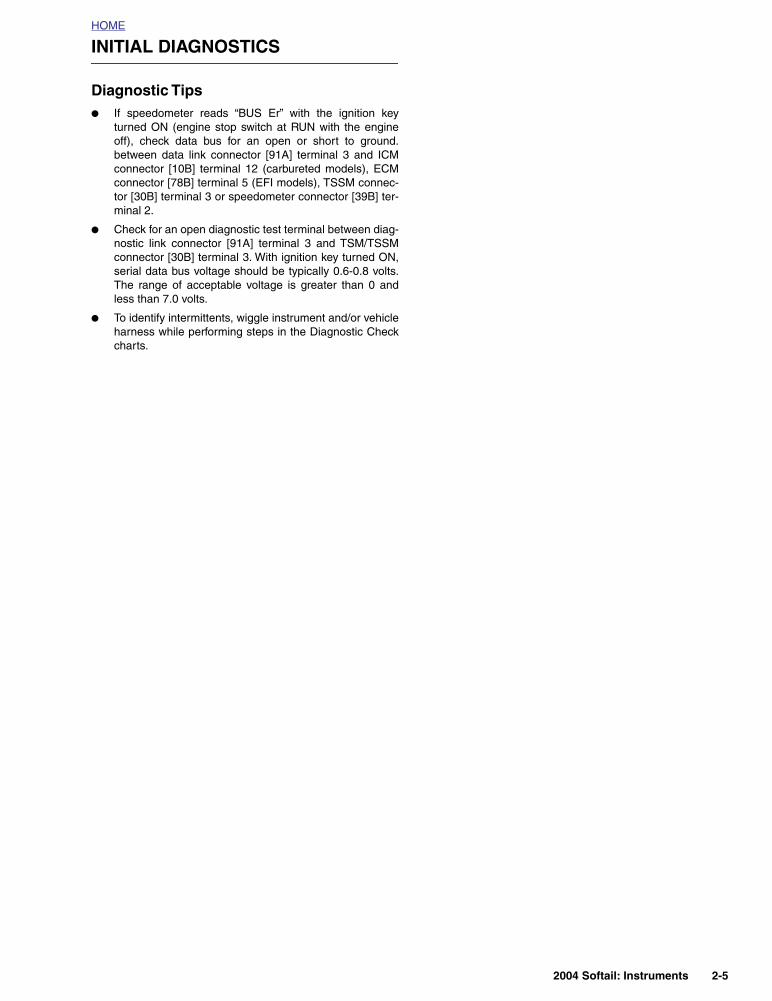
Reset Switch Closed
Code B1008 will be set if switch terminals are in a constantshorted state.
DIAGNOSTICS
Diagnostic Notes
The reference numbers below correlate with the circled num-bers on the 2.11 flow chart.
1. Connect BREAKOUT BOX (Part No. HD-42682) andADAPTERS (Part No. HD-41606) between wire harnessand speedometer, leaving speedometer discon-nected.
Table 2-12. Code Description
DTC DESCRIPTION
B1008 Reset switch closed
Figure 2-23. Reset Switch
7495
2004 Softail: Instruments 2-29

HOME
Figure 2-24. Reset Switch Circuit
123456789
101112
d0723x2x
[39B][39A]
BK
Speedometer
Reset Switch
BK
Table 2-13. Wire Harness Connector in Figure 2-24.
NO. DESCRIPTION TYPE LOCATION
[39] speedometer 12-place Packard back of speedometer
2-30 2004 Softail: Instruments

HOME
Test 2.11RESET SWITCH CLOSED: DTC B1008
Remove reset switch rubber boot. Clear codes using 2.3 SPEEDOM-
ETER SELF DIAGNOSTICS. Codes still present?
YES
NO
Replace switch.
NO
Replace boot.
YES
Replace speedometer.
Clear codes using speedometer self diagnostics.See 2.3 SPEEDOMETER SELF DIAGNOSTICS.Confirm proper operation with no check enginelamp.
With speedometer disconnected, measure resistance between terminals 8 and 11
(black) on Breakout Box. Resistance should be less than 1 ohm with switch depressed
and infinity ohms when released. Is it?
1
2004 Softail: Instruments 2-31

HOME
DTC U1016, U1255 2.12
GENERAL
Loss of ICM/ECM Serial Data
The serial data connector provides a means for the ignitioncontrol module (ICM) or electronic control module (ECM),TSM/TSSM and speedometer to communicate their currentstatus. When all operating parameters on the serial data linkare within specifications, a state of health message is sentbetween the components. A DTC U1016 indicates that theICM/ECM is not capable of sending this state of health mes-sage
DIAGNOSTICS
Diagnostic Notes
The reference numbers below correlate with the circled num-bers on the Test 2.12 flow chart.
1. Connect BREAKOUT BOX (Part No. HD-42682) (gray)between TSM/TSSM connector [30A] and wire harnessconnector [30B]. See 3.11 BREAKOUT BOX: TSM/TSSM.
2. Connect BREAKOUT BOX (Part No. HD-42682) (black)between ICM connector [10A] and wiring harness con-nector [10B]. See 4.6 BREAKOUT BOX: ICM
3. Connect BREAKOUT BOX (Part No. HD-43876)between wire harness and ECM. See 5.7 BREAKOUTBOX: EFI.
Table 2-14. Code Description
DTC DESCRIPTION
U1016
Loss of all ICM/ECM serial data (state of health)
Loss of vehicle speed
Loss of vehicle inhibit motion
Loss of powertrain security status
U1255 Serial data error/missing message
Figure 2-25. ECM
Figure 2-26. Data Link Connector
7775
1. Terminal 1: flash pin-EFI models (Lt GN/R)2. Terminal 2: ground (BK)3. Terminal 3: serial data (Lt GN/V)4. Terminal 4: power (GY)5. Protective cap
6924
14
32
5
2-32 2004 Softail: Instruments

HOME
Figure 2-27. Serial Data Circuit: EFI Models
3
1
2
4
51
321 654 987 121110321 654 987 121110321 654 987 121110
321 654 987 121110
d0700c8x
ECM
Data linkconnector
TSM/TSSM
[30B]
[30A]
[91A]
BK
LtGN/V
[78B]
[78A]
Speedometer
12VBattery
O
BK
Ser
ial d
ata
[39B]
[39A]
LtG
N/R
Fla
sh p
in
BN/GY
12Vinstrument
12VIgnition
GY
LtG
N/V
O/W
12VAccessory
LtG
N/V
LtG
N/V
BN
/GY
G
Y BK
Table 2-15. Wire Harness Connectors in Figure 2-27.
NO. DESCRIPTION TYPE LOCATION
[30] turn signal/security module 12-place Deutsch electrical panel behind fender extension
[39] speedometer 12-place Packard back of speedometer
[78]electronic control module (ECM):EFI models
36-place Packard under seat
[91] data link connector 4-place Deutsch under seat
2004 Softail: Instruments 2-33

HOME
Figure 2-28. Serial Data Circuit: Carbureted Models
12
3
1
2
4
321 654 987 121110321 654 987 121110321 654 987 121110
321 654 987 121110
ICM
Data linkconnector
TSM/TSSM
LtG
N/V 12V
ignition
GY
[30B]
[30A]
[91A]
LtG
N/V
BK
LtGN/V
LtGN/V
[39B]
[39A]
[10B]
[10A]
Speedometer
12VBattery
BK
Ser
ial d
ata
d0721c8x
BN/GY
O/W
12Vinstrument
O
12VAccessory
BK
BN
/GY
G
Y
Table 2-16. Wire Harness Connectors in Figure 2-28.
NO. DESCRIPTION TYPE LOCATION
[10]ignition control module (ICM): car-bureted models
12-place Deutsch under seat
[30] turn signal/security module 12-place Deutsch electrical panel behind fender extension
[39] speedometer 12-place Packard back of speedometer
[91] data link connector 4-place Deutsch under seat
2-34 2004 Softail: Instruments

HOME
Test 2.12LOSS OF ECM SERIAL DATA: DTC U1016
Can you read ECM/ICM hardware P/N? See 2.3 SPEEDOMETER SELF DIAGNOSTICS.
Clear codes using speedometer self diagnostics.See 2.3 SPEEDOMETER SELF DIAGNOSTICS.Confirm proper operation with no check enginelamp.
NO or “No Rsp”YES
YES
NO
Repair open on Lt GN/V wire.
Install Breakout Box on TSM/TSSM1
Replace ICM. Reprogram and learn
password.
CARBURETED MODELS
EFI MODELS
Check continuity between termi-nal 2 (black) of speedometer
Breakout Box and terminal 5 of ECM Breakout Box.Continuity present?
2 3
YES
Replace ECM. Reprogram and learn
password.
Check continuity between termi-nal 3 (gray) of TSM/TSSM Break-
out Box and terminal 5 of ECM Breakout Box.
Continuity present?
Install Breakout Box on TSM/TSSM.1
CARBURETED MODELS EFI MODELS2 3
YES
NO
While wiggling harness, check continuity between Breakout Box terminal 3 (gray) and Breakout
Box terminal 12 (black).Continuity present?
YES
While wiggling harness, check conti-nuity between terminal 3 (gray) of TSM/TSSM Breakout Box and ter-
minal 5 of ECM Breakout Box.Continuity present?
Clear codes. Test ride. Does DTC U1016
return?Repair intermittent on Lt GN/V wire.
YES
Replace ICM. Reprogram and learn
password.
NO
No trouble found.
Clear codes. Test ride. Did DTC U1016 return?
Replace ECM. Reprogram and learn
password.
YES NO
No trouble found.
Check continuity between Breakout Box terminal 3 (gray) and Breakout Box
terminal 12 (black).Continuity present?
2004 Softail: Instruments 2-35

HOME
DTC U1064, U1255 2.13
GENERAL
Loss of TSM/TSSM Serial DataThe serial data connector provides a means for the ignitioncontrol module (ICM) or electronic control module (ECM),TSM/TSSM and speedometer to communicate their currentstatus. When all operating parameters on the serial data linkare within specifications, a state of health message is sentbetween the components. A diagnostic trouble code (DTC)U1064 indicates that the TSM/TSSM is not receiving thisstate of health message.
DIAGNOSTICS
Diagnostic NotesThe reference numbers below correlate with the circled num-bers on the Test 2.13 flow chart.
1. Connect BREAKOUT BOX (Part No. HD-42682) as fol-lows:
a. Mate black socket housing on Breakout Box withspeedometer connector [39] using SPEEDOMETERHARNESS ADAPTER (Part No. HD-46601).
b. Mate black pin housing on Breakout Box with speed-ometer harness connector [39B] using SPEEDOM-ETER HARNESS ADAPTER (Part No. HD-46601.
c. Mate gray socket housing on Breakout Box withTSM/TSSM connector [30A].
d. Mate gray pin housing on Breakout Box with har-ness connector [30B].
Table 2-17. Code Description
DTC DESCRIPTION
U1064 Loss of TSM/TSSM serial data
U1255 Serial data error/missing messageFigure 2-29. TSM/TSSM
Figure 2-30. Data Link Connector
7844
1. Terminal 1: flash pin-EFI models (Lt GN/R)2. Terminal 2: ground (BK)3. Terminal 3: serial data (Lt GN/V)4. Terminal 4: power (GY)5. Protective cap
6924
14
32
5
2-36 2004 Softail: Instruments

HOME
Figure 2-31. Serial Data Circuit: EFI Models
3
1
2
4
51
321 654 987 121110321 654 987 121110321 654 987 121110
321 654 987 121110
d0700c8x
ECM
Data linkconnector
TSM/TSSM
[30B]
[30A]
[91A]
BK
LtGN/V
[78B]
[78A]
Speedometer
12VBattery
O
BK
Ser
ial d
ata
[39B]
[39A]
LtG
N/R
Fla
sh p
in
BN/GY
12Vinstrument
12VIgnition
GY
LtG
N/V
O/W
12VAccessory
LtG
N/V
LtG
N/V
BN
/GY
G
Y BK
Table 2-18. Wire Harness Connectors in Figure 2-31.
NO. DESCRIPTION TYPE LOCATION
[30] turn signal/security module 12-place Deutsch electrical panel behind fender extension
[39] speedometer 12-place Packard back of speedometer
[78]electronic control module (ECM):EFI models
36-place Packard under seat
[91] data link connector 4-place Deutsch under seat
2004 Softail: Instruments 2-37

HOME
Figure 2-32. Serial Data Circuit: Carbureted Models
12
3
1
2
4
321 654 987 121110321 654 987 121110321 654 987 121110
321 654 987 121110
ICM
Data linkconnector
TSM/TSSM
LtG
N/V 12V
ignition
GY
[30B]
[30A]
[91A]
LtG
N/V
BK
LtGN/V
LtGN/V
[39B]
[39A]
[10B]
[10A]
Speedometer
12VBattery
BK
Ser
ial d
ata
d0721c8x
BN/GY
O/W
12Vinstrument
O
12VAccessory
BK
BN
/GY
G
Y
Table 2-19. Wire Harness Connectors in Figure 2-32.
NO. DESCRIPTION TYPE LOCATION
[10]ignition control module (ICM): car-bureted models
12-place Deutsch under seat
[30] turn signal/security module 12-place Deutsch electrical panel behind fender extension
[39] speedometer 12-place Packard back of speedometer
[91] data link connector 4-place Deutsch under seat
2-38 2004 Softail: Instruments

HOME
Test 2.13LOSS OF TSM/TSSM SERIAL DATA: DTC U1064, U1255
Can you read TSM/TSSM hardware P/N? See 2.3 SPEEDOMETER SELF DIAGNOSTICS.
NO or “No Rsp”YES
YESNO
Install Breakout Box on speedometer.Check for continuity between terminal 3 (gray) and terminal 2 (black) of Breakout
Box Continuity present?
1
Replace TSM/TSSM. Learn password.
Clear codes using speedometer self diagnostics.See 2.3 SPEEDOMETER SELF DIAGNOSTICS.Confirm proper operation with no check enginelamp.
Install Breakout Box on speedometer.While wiggling harness, check for continuity
between terminal 3 (gray) and terminal 2 (black) of Breakout Box.
Continuity present?
YES
Repair intermittent on Lt GN/V wire.
NO
1
Clear DTCs. Test ride. Does DTC U1064
return?
YES
Replace TSM/TSSM. Learn password.
NO
No trouble found.
Repair open on Lt GN/V wire.
2004 Softail: Instruments 2-39

HOME
DTC U1300, U1301 OR “BUS ER” 2.14
GENERAL
Serial Data Low or Serial Data Open/High
See Figure 2-33. The typical serial data voltage range is 0volts (inactive) to 7 volts (active). Due to the short pulse, volt-ages will be much lower on a DVOM. In analog mode, aDVOM reading serial data will show continuous voltage whenactive, typically 0.6-0.8 volts. The range for acceptable opera-tions is 0-7.0 volts.
DIAGNOSTICS
Diagnostic Tips
● If serial data is shorted, these codes will automaticallycause the check engine lamp to illuminate. The odometerwill read “Bus Er” in this condition.
● Diagnostic trouble codes (DTCs) P1009 and P1010 mayaccompany DTCs U1300 and U1301.
Diagnostic Notes
● If a U1300, U1301 or “BUS Er” is present on carburetedmodels, perform diagnostic procedures listed in 4.10STARTS, THEN STALLS.
● If a U1300, U1301 or “BUS Er” is present on EFI models,perform diagnostic procedures listed in 5.12 STARTS,THEN STALLS.
Table 2-20. Code Description
DTC DESCRIPTION
U1300 Serial data low
U1301 Serial data open/highFigure 2-33. Data Link Connector [91A]
2
7774
1
1. Data link connector [91A]2. Protective rubber plug
2-40 2004 Softail: Instruments