Harlequin - Amigaamiga.resource.cx/manual/Harlequin.pdf · The Harlequin manual was produced using...
67
HARLEQUIN The 32 bit Frame Buffer User Manual 1991
Transcript of Harlequin - Amigaamiga.resource.cx/manual/Harlequin.pdf · The Harlequin manual was produced using...
HARLEQUIN
The 32 bit Frame Buffer
User Manual
1991

COPYRIGHT
This manual is the Copyright (c) 1990 ofKeybonus Ltd. All Rights Reserved. Thisdocument may not, in whole or in part, becopied, photocopied, reproduced, translated,or reduced to any electronic medium ormachine readable form, without prior writtenconsent, in writing, of Keybonus Ltd.
Marketed internationally byAmiga Centre Scotland.
Harlequin HouseWalkerburnPeeblesshire
Scotland EH43 6AZTel: 089 687 583Fax: 089 687 456
TABLE OF CONTENTS
Introduction ......................................................... 1Registration, support and upgrades ....................... 1Installing The Harlequin Board ........................... 2What it does ........................................................ 7Software Interface & Programmers guide ........... 11 - 54
General outline ........................................... 11 - 14Overview ............................................ 11Software Outline ................................ 12Cardless software ............................... 13Bug reporting ..................................... 14
Interface Library .................................................. 15 - 35Interface Device .................................................. 37 - 54Product specification ........................................... 56 - 59
LIST OF FIGURES
Mother board (Links) ........................................ 6External connections ......................................... 57

ACKNOWLEDGEMENTS
The Harlequin manual was produced using Professional Page V 2.0on an Amiga 3000.
Keybonus would like to take this opportunity to thank the following:-
Jan Jones, Andrew Moss and Alan Tucker for their confidencein bringing the original Harlequin Frame Buffer (a jumble ofwires connected to the parallel port of an Amiga 500) to AmigaCentre Scotland. They worked enthusiastically at all times ofday and night to improve the specification and to implement iton an Amiga 2000 internal card.
V.A. Elliott M.C. for his continuous interest in the project, forhis belief in it, and his help in creating the organisation tosuccessfully develop it.
BBDP for the quality and professionalism that they incorporatedin the design and manufacture, and for magnificent efforts toenable the pre-production boards to be successfullydemonstrated at shows in London and Cologne.
David Grieve of Ekka Electronics for not only providing asuperb handsome design, but also for his willingness to discussat midnight the implementation of the latest ideas for revisionsto the specification.
Ian Ballantyne of Scope Picture Production, Glasgow, for hishelp and advice in ensuring that the Harlequin fully meets therequirements of IEEE 470-1 broadcast specification.
Various staff at CBM, for their help at various stages especiallyon the software interface.

Mike Tinker who produced software to load images to theHarlequin before he even had a board. He designed andimplemented the software interface for the Harlequin, whichsoftware developers from all over the world have commented onenthusiastically.
All staff at the Amiga Centre Scotland for their time andpatience.
This is by no means an exhaustive list of those we should thank,as this would take several pages of the manual, please regardthis as a personal thanks to any one involved.
Lastly our sincere thanks to you for your purchase of theHarlequin.

INTRODUCTION
Congratulations on the purchase of your new Harlequin FrameBuffer. The Harlequin is a 32 bit Frame Buffer for the Amigacomputer, this allows in excess of 16.7 million colours to bedisplayed on screen. So you can now see the advantage offered by24 bit graphics software packages. You will notice this leaves anextra 8 bits, which we call the Alpha channel. This can be used formore sophisticated equipment to allow linear keying and isdiscussed in greater detail in the ‘What it does’ chapter.
The Harlequin board has been designed to provide compatibilitywith a range of additional accessories, including Genlocks, singleframe controllers, and other video equipment. The board is designedfor the Zorro II bus used in the Amiga range of computers, and hasbeen satisfactorily tested in most A2000 and A3000 versions.
The output from the Harlequin is totally independent from theAmiga video, offering a range of resolutions in both interlace andnon interlace modes. This allows one or more boards to beincorporated in an Amiga each driving a separate device. TheAmiga’s multi tasking allows different images to be output fromeach Harlequin while retaining the original Amiga monitor output.
REGISTRATION
Keybonus treats the support for the Harlequin and other products itproduces very seriously. We are continually improving our existingproducts and producing new products, and normally make theseimprovements available in the form of product upgrades. It istherefore imperative that you fill out and return the registration cardyou received with this product. Failure to do so will mean we maybe unable to contact you regarding upgrades to the Harlequin.Furthermore technical support will not be given to anyone who isnot in our registered user database. So please send in yourregistration card.
Page 1
INSTALLING THE HARLEQUIN BOARD
WARNING
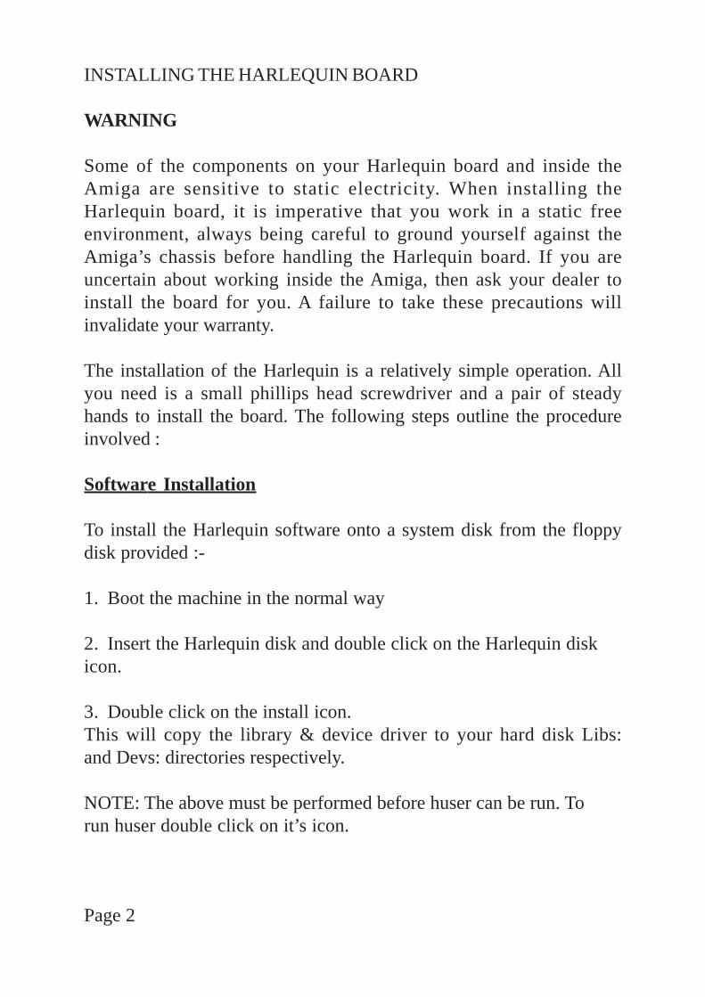
Some of the components on your Harlequin board and inside theAmiga are sensitive to static electricity. When installing theHarlequin board, it is imperative that you work in a static freeenvironment, always being careful to ground yourself against theAmiga’s chassis before handling the Harlequin board. If you areuncertain about working inside the Amiga, then ask your dealer toinstall the board for you. A failure to take these precautions willinvalidate your warranty.
The installation of the Harlequin is a relatively simple operation. Allyou need is a small phillips head screwdriver and a pair of steadyhands to install the board. The following steps outline the procedureinvolved :
Software Installation
To install the Harlequin software onto a system disk from the floppydisk provided :-
1. Boot the machine in the normal way
2. Insert the Harlequin disk and double click on the Harlequin diskicon.
3. Double click on the install icon.This will copy the library & device driver to your hard disk Libs:and Devs: directories respectively.
NOTE: The above must be performed before huser can be run. Torun huser double click on it’s icon.
Page 2
Hardware installation
1. Ensure the Amiga is turned off, and disconnected from thepower supply, along with any peripherals attached to it.
2. Remove the Amiga’s case. This is secured by a number ofphillips head screws, and requires the use of the aforementionedscrewdriver. In the case of the Amiga 2000 and 1500 there are fivescrews, two located on each side of the case near the bottom, and thefifth is located in the center of the rear panel, near the top. (Becareful to place the screws where they can not fall into the the opencomputer.) Once loose the case should be slid forward, then liftedoff, being careful not to snag any wires in the process.
3. Having exposed the Amiga’s guts, be sure to ground yourself bytouching the exposed metal on the chassis. Locate a vacant Zorro IIslot. In the case of the Amiga 2000 and 1500 these are the fiveparallel slots towards the front of the motherboard. Unscrew themetal cover plate from behind the selected slot, and remove it,saving the screws for use later.
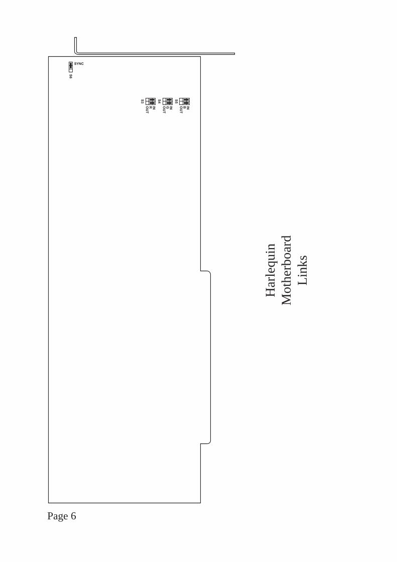
4. Remove the Harlequin board from its packaging. If sync ongreen is required the jumper at S6 should join the middle and syncpins, if not required then the jumper should be moved to join themiddle pin and the pin towards the centre of the board. (see thediagram at the end of this section).
Page 3

5. Align the board with the selected slot. There is a plastic cardguide at one end, and this should be used to correctly align the cardwith the slot. Push the card gently but firmly home into the slot,ensuring that the board does not contact any other boards in theprocess (in some cases this may mean leaving a vacant slot adjacentto the Harlequin board). Attach the mounting bracket using thescrews saved at the last step.
6. The Harlequin board is now installed in the Amiga, and you canreplace the case and resecure it with the original screws.
7. Ensure the Amiga is turned off then reconnect the power supply.
8. Re boot your Amiga as normal. If the board is installed correctlythe computer will boot exactly as it did before installation.
9. Using the floppy disk provided, or a copy of it. Run the testprogram ‘huser’. The program is mouse driven with large blueselection buttons. Select :- screen format, Buffer 0, any resolution,interlaced then System info. The program should report the detailsof the Harlequin board installed, with the memory found displayedin Megabytes.
10. This completes the installation of the Harlequin board in theAmiga, however the board now needs to be connected to the outsideworld. In most cases this will be a display monitor or piece of videoequipment.
Page 4

11. Power off the Amiga, prior to connecting any leads to theHarlequin board.
12. Connect one end of the lead to the Video output from theHarlequin board, and the other end to your display or videoequipment.
13. Power on the equipment, and re-boot the Amiga.
14. Using the floppy disk provided, or a copy of it. Run the testprogram ‘huser’. The program is mouse driven with large blueselection buttons. Select :- screen format, Buffer 0, any resolution,interlaced, clear screen then Rectangles or lines. A simple testpattern of rectangles or lines should be visable on the display.
The Harlequin board is now fully installed. For further informationon what it can achieve, read the chapter on ‘WHAT IT DOES’.
Page 5
Page 6
��
�����
�
�����
��
�� ��
��
����
Har
lequ
inM
othe
rboa
rdLi
nks
WHAT IT DOES
Harlequin gives you a great image! If you care about your image,whether its your image with customers or friends, or the image youcreate in your Amiga, Harlequin will enhance it.By giving you a choice of nearly 17 million colours for every pixel,Harlequin faithfully delivers your image whether it comes from thereal world or from the limits of your own creative genius. Bywhatever means you intend to let the world see the fruits of yourefforts, Harlequin’s output lets you choose stills or animation,broadcast quality video, or photorealistic, high resolution monitordisplay.
Loading images to Harlequin
If you are using an application package which has a standardHarlequin driver then simply follow the instructions of yourapplication package and enjoy the Harlequin output.If your image file is in one of the many formats supported by theRasterlink software delivered with your Harlequin then use Rasterlinkto load your image to Harlequin. Rasterlink may be usedindependently from Harlequin to convert image files from one formatto another.
Taking images from Harlequin
Depending on how you wish to view your image, you will make useof some or all of Harlequin’s outputs:-
RGB + Composite sync (1v pk-pk 75Ohms)Digital key outputAlpha channel (1v pk-pk 75Ohms)Genlock control lines
and Harlequin’s configuration modes:-
Page 7
Double buffering (3000 & 4000 only)3 ResolutionsInterlaced/Non-interlaced
RGB + Composite Sync
The main outputs from Harlequin are the red, green and blue signalswhich may be obtained individually with sync on green (switchable).Inside Harlequin, 8 bits are used to define each of the red, green andblue values for each pixel. In high res there are 910x576 pixels perimage (910x486 NTSC). For each of those pixels the colourdefinitions use 24 bits leaving 8 bits for other effects.
Digital key output
One bit is connected to the video output as a simple bit mask to enableoverlays of external video on an on/off basis. The Harlequin outputis effectively stencilled on the external video.
Alpha channel - Linear keying
If simple on/off overlays are not enough for you then the Harlequingives you access to a full 8 bit Alpha channel which is output as a 256level linear key, which can be used to control more advanced videoequipment. With this capability it is possible to produce stunningsuperimpositions of text and graphics over live video.
Consider values 0 to 255 on the Alpha channel as representing howtransparent the Harlequin image will be when overlaid on the externalvideo. With value 0 only the Harlequin image is seen, while 255gives wholly external video. Intermediate values give the appropriatemixture. Used selectively, this allows smooth transitions at the edgesof computer text and graphics when overlaid on video.
Page 8
When used globally on all pixels it allows you to fade external videoto or from a specific colour, or cross fade between Harlequin graphicsand external video. The end result depends on your own creativity.
Genlockability
The Harlequin’s output has the synchronising signals required bygenlocking devices. To mix video signals it is necessary tosynchronise them. Harlequin’s broadcast quality output is ideal. Ifyour video equipment is prone to drift and you would like the abilityto trim the Harlequin’s output to match, then providing you havepurchased a model /T, you can. Please refer to appendix NN fordetails.
Double buffering
On Harlequin 3000 and 4000 there are double buffers. This meansthat one frame may be loading while the other is on display.Switching between frames is accomplished by a software switch andis a very effective means of producing a slide show or limited realtime animation. Animators can flick between two adjacent frames asnecessary.
Interlace/Non-Interlace
On a suitable monitor, Harlequin’s output is superb and rock steady innon-interlace mode. When working with video it is necessary,because of the video standards for T.V., to use Harlequin’s interlacemode.
Page 9

Page 10
Harlequin Graphics Card Overview================================
The Harlequin graphics card supports up to 32 bit pixels, with 24 bitsdisplayed. The pixels are broken down into 8 bits each of red, green,blue and alpha. The bits are number from 0 to 31 with the lowest bit(bit 0) being the least significant bit of the alpha channel and thehighest bit (bit 31) being the most significant bit of the red channel.
The standard Amiga display uses the pixel value to index into a 12 bitcolour palette, on the Harlequin card this is not necessary as the 24bits of pixel data are used as the colour information, this gives inexcess of 16 million colours.
The alpha channel has many uses even though it is not displayed, to alarge extent the use can be dictated by the application. Certainfacilities are designed into the board based on the alpha channeloutput. The lowest bit (bit 0) is connected to the video connector as asingle bit mask output, this enables simple video overlays where theexternal video is either on or off. The whole of the alpha channel isalso output as a 256 level linear key which is able to control moreadvanced video equipment to allow variable levels of video/graphicsoverlay, thereby allowing smooth transitions to be made betweengraphic objects generated by the card and external video.
The Harlequin graphics card supports either 1 or 2 buffers, with orwithout alpha channels fitted. If a double buffer card has alphamemory there will be alpha on both buffers, no card will have 2buffers but only 1 alpha.
The Harlequin card supports the following resolutions in bothinterlace and non-interlace:
910 x 576 (PAL version) 910 x 486 (NTSC version)832 x 576 (PAL version) 832 x 486 (NTSC version)740 x 576 (PAL version) 740 x 486 (NTSC version)
Page 11

Software Outline===============
The software has been designed for implementation in 3 levels. Thecurrent release implements level 1 only. Level 1 provides the basicfunctions of card allocation, pixel operations and block operations.Additional, higher level, functions are scheduled for levels 2 and 3.The level 1 functions enable all operations to be constructed bycompounding the basic drawing operations into higher leveloperations, such as line drawing, cursors and masking operations. Ifhigher level functions are designed into applications they can beremoved and replaced by Harlequin interface software calls as andwhen they become available.
Currently no standards are defined for deep bitmaps for use with theAmiga but Keybonus, in conjunction with Amiga Centre Scotland, areactively involved in discussions with other members of GRAphicsExtensions for the Amiga (GRAFEXA) to establish a standard. Asstandards are defined it is intended that they will be integrated into theinterface software, this will ensure as wide a range of software isavailable for the Harlequin card as possible. For the developer thiswill allow 1 version of a product to be developed which will have aswide a market as possible. Registered developers for the Harlequincard will of course be kept up to date as any changes or developmentsare made.
There are 2 methods of accessing the Harlequin card, an Exec styleshared library and a device driver. The device driver is built upon thefunctions of the library so that a single method of controlling cardaccess can be provided. While only the library is required in the Libs:directory to access its functions, it is necessary to have both thelibrary installed and the device driver in the Devs: directory whendevice driver commands are used.
With the Level 1 software, applications are given exclusive access tothe individual buffers. With future levels windowing may be
Page 12

implemented, this will have the effect of allowing different screensizes to be opened than are supported in hardware, ensure that the thescreen allocated by a call to HOpenScreen is adequate for the purposeyou have in mind. If it is essential that a full buffer is always allocated(for example double buffered animation) set the EXCLUSIVE bit inthe HNewScreen. Type field before opening the screen. Rememberthat the full palette is always available with the Harlequin card, evenwhen multiple windows are open, so that in the many occasions whena custom screen was required with the normal Amiga display it is notalways necessary with the Harlequin.
When requesting screens by screen number please note that the lowestscreen number, zero, is the first buffer on the first card (looking fromthe front of the Amiga this is the Harlequin card in the right mostslot). The next screen will be 1 which is the second buffer of the firstcard, if fitted. Any second card fitted will always have the first buffernumbered 2, even when the first card didn’t have a second buffer. Theinterface software will support a virtually unlimited number of cards.
No calls should be made to any Harlequin function while Forbid orDisable are active, except where indicated in the documentation, as adeadlock could result. Deadlocks would be caused when task A hasuse of the card but a Forbid by task B never allows task A tocomplete, and therefore relinquish control of the card, leaving task Bwaiting for control.
Cardless Software=================
A version of the library is supplied that will work without a Harlequincard fitted and simulate the actual operations available with the card.The library is located in the libs directory on the developers disk andcalled harlequin_cardless.library, it will be necessary to copy this fileto your assigned libs: directory and rename it to harlequin.library. The
Page 13

software simulates a double buffered PAL card with alpha channelsfitted.
When used with a standard A2000 and 68000 the library will operateat approximately the same speed as an A2000 and Harlequin cardconfiguration. When used with an A2000 and accelerator card or anA3000 the library will run faster than normal, this is because thesimulated writes will be to 32 bit memory at full processor speed. It isunfortunately not possible to give timings for how much of a speedincrease this will provide as it very much depends on the operation.The only way to obtain accurate timings is to test with the Harlequincard fitted!
Bug Reports===========
This software is pre-release and we therefore request detailed bugreports. While this level of the software has a fairly limited set offunctions there are many variations possible with many of thefunctions, some may have slipped through early testing (theHClipBlockScreen has 256 possible combinations of source/destDrawModes!).
The interface software is designed to enable application programmersto write simpler drawing functions and to simplify porting existingapplications to the Harlequin card, many options were left open sothat developers could make requests for functions that could beincluded, either before public release or in higher levels of theinterface. If there is something that you would find indispensable thenplease pass your comments onto Amiga Centre Scotland.
Page 14
NAMEHOpenScreen — allocate and set format of a screen
SYNOPSISHScreen = HOpenScreen(HNewScreen)D0 A0
struct HScreen *HOpenScreen(struct HNewScreen *)
FUNCTIONAllocates and initialises a HScreen structure, sets the screenformat according to the requirements in the HNewScreenstructure. If the HNewScreen.Type HDISPLAY flag is set thescreen display will be turned on, although the display may stillbe hidden if another buffer is in use on the same card.
Before a call to the HOpenScreen function the HNewScreenstructure must be initialised with the required screen dimensionsand any Flags necessary. The HNewScreen structure is notrequired after the call and, unless screen conversions are to takeplace, can be discarded.
With the Level 1 library, if the screen requested is already openthen the HOpenScreen function will fail. Ensure allHOpenScreen calls are paired with a HCloseScreen call toensure that the screen is freed for use by other applications.
To open a double buffered display use 2 calls to HOpenScreen,the screens on the same card will have consecutive numberswith the first numbered even and the second odd, eg. 0/1, 2/3.Setting the HDOUBLEBUFFER flag in HNewScreen.Type willensure that a screen is only allocated if there is a second bufferavailable on the same card, the HDOUBLEBUFFER flag mustbe cleared before attempting to open the second buffer. To openthe second, matching, buffer use the HScreen.ScreenNumberfrom the HScreen returned by the first HOpenScreen call with
Page 15
the lower bit changed. Provided that the HDISPLAY bit is notset in either of the HNewScreen structures the HOpenScreen callcan be surrounded with a Forbid/Permit pair.
Setting HNewScreen.ScreenNumber to -1 will cause the firstavailable screen with the required attributes to be allocated.
Calls can be made to HGetScreenInfo to establish the screensavailable and their formats.
The screen is not cleared when opened, to open a screen with thedisplay on and cleared use the following sequence of functioncalls:
HOpenScreen - with HNewScreen.Type HDISPLAY bitclearHClearScreenHScreenFunction - with mask = SCREEN_ON
Unless the requested type was HBORDERLESS, future Levelsof the library may draw a border around the screen (toimplement windows), the borders will be drawn outside theallocated screen area so that the pixel at location (0,0) will bethe first pixel in the drawing area upper left corner, not in theborder.
INPUTSHNewscreenPointer to HnewScreen structure.
RESULTHScreenPointer to HScreen structure on success, else zero
BUGSSEE ALSO
HcloseScreen, HGetScreenInfo
Page 16
NAMEHCloseScreen — close a Harlequin screen previously opened bya call to HOpenScreen
SYNOPSISHCloseScreen(screen)A0
void HCloseScreen(struct HScreen *)
FUNCTIONThis function closes a screen previously opened with a call toHOpenScreen. The HScreen structure allocated by the call toHOpenScreen will be freed by the call.
If another screen is open on the card it will be brought to thefront.
INPUTSscreenPointer to HScreen structure allocated by HOpenScreen
RESULTNone
BUGS
SEE ALSOHOpenScreen
Page 17

NAMEHSetPixel — set a pixel in an open screen
SYNOPSISHSetPixel(screen, colour, x, y)A0 D0 D1 D2
void HSetPixel (struct HScreen *,ULONG,SHORT,SHORT)
FUNCTIONSets the colour of a pixel on screen. The colour RGB values areplaced in the upper 3 bytes of the function argument colour andthe alpha in the lower byte (when alpha is being used). Thescreen origin is (0,0) located in the upper left corner of thedisplay.
If the (x,y) coordinates are outside the display area the pixel willnot be drawn.
When setting the pixel colour the settings inHScreen.DrawMode are taken into account, this allows writingto take place only to those channels that are enabled.
INPUTSscreenPointer to an open HScreen structcolourColour value to place in pixel(x.y)Point within the screen that the pixel is to be written
RESULTNone
BUGSSEE ALSO
HReadPixel, HWritePixel
Page 18
NAMEHReadPixel — read a pixel colour from an open screen
SYNOPSIScolour = HReadPixel (screen, x , y)D0 A0 D0 D1
ULONG HReadPixel(struct HScreen *,SHORT,SHORT)
FUNCTIONReads the colour of the specified pixel in the specified screen.The RGBA value for the pixel is placed in the return valuecolour. No account is taken of HScreen.DrawMode so that thefull 32 bit pixel value is returned. The screen origin is 0,0located in the upper left corner of the display.
No check is made for out of bounds (x,y) values, an out ofbounds read will return an unspecified colour.
INPUTSscreenPointer to open HScreen structure(x,y)Point within the screen that the colour is to be read from
RESULTcolourRGBA value from screen x,y location with RGB values inupper 3 bytes and alpha in lower byte
BUGS
SEE ALSOHSetPixel, HWritePixel
Page 19
NAMEHWritePixel — writes the colour from HScreen.FgPen into thescreen
SYNOPSISHWritePixel (screen, x, y)A0 D0 D1
void HWritePixel(struct HScreen *,SHORT,SHORT)
FUNCTIONWrites the colour from HScreen.FgPen to the pixel located at(x,y) in the specified screen. The screen origin is (0,0) located inthe upper left corner of the display.
If the (x,y) coordinates are outside the display area the pixel willnot be drawn.
When setting the pixel colour the settings inHScreen.DrawMode are taken into account, this allows writingto take place only to those channels that are enabled.
INPUTSscreenPointer to open HScreen structure(x,y)Point within the screen that the FgPen is to be written
RESULTNone
BUGS
SEE ALSOHSetPixel, HReadPixel
Page 20
NAMEHClipBlockScreen — copies image data from an ImageBlockstructure to the screen with clipping
SYNOPSISerror = HClipBlockScreen(block, sourcex, sourcey, screen,D0 A0 D0 D1 A1destx, desty, sizex, sizey)D2 D3 D4 D5
LONG HClipBlockScreen(struct ImageBlock *, SHORT,SHORT, struct HScreen *, SHORT, SHORT,SHORT,SHORT)
FUNCTIONCopies a rectangle of image data from a source ImageBlocklocated in Amiga main memory to the previously opened screen.Clipping will take place should the source image data not fittotally within the screen area.
The ImageBlock.Flags will be considered when the copy isperformed, thus allowing packed data or seperate RGB channelsto be used. When copying the pixel, the settings inHScreen.DrawMode are taken into account, this allows writingto take place only to those channels that are enabled.
No account is taken of the source ImageBlock size whenclipping, if the image data is smaller than the size of therectangle specified in the function parameters, random Amigamain memory may be written to the display.
INPUTSblockPointer to ImageBlock structure containing image data to copyto screen(sourcex,sourcey)Upper left corner location from which to start copy
Page 21

screenPointer to open HScreen structure for destination(destx,desty)Upper left corner location to which the image data will start tobe copied(sizex,sizey)Horizontal and vertical size of source image data to be copied
RESULTerror-ve if completely off screen0 if completely on screen+ve if clipping took place
BUGS
SEE ALSOHClipScreenBlock, HClipScreenScreen
Page 22
NAMEHClipScreenBlock — copies image data from a screen to apreviously allocated ImageBlock with clipping
SYNOPSISerror = HClipScreenBlock(screen, sourcex, sourcey, block,D0 A0 D0 D1 A1destx, desty, sizex, sizey)D2 D3 D4 D5
LONG HClipScreenBlock(struct HScreen *, SHORT, SHORTstruct ImageBlock *, SHORT,SHORT,SHORT,SHORT)
FUNCTIONCopies a rectangle of image data from a source screen located indisplay memory to a previously allocated ImageBlock structurewith the image data memory allocated. Clipping will take placeshould the source image data not fit totally within theImageBlock area.
The ImageBlock.Flags will be considered when the copy isperformed, thus allowing simple packing of the image data orseparation of the RGB values to take place in Amiga mainmemory.
INPUTSscreenPointer to open HScreen structure for source(sourcex,sourcey)Upper left corner location from which to start copyblockPointer to ImageData structure to which screen data will becopied(destx,desty)Upper left corner location to which the image data will start tobe copied
Page 23
(sizex,sizey)Horizontal and vertical size of source image data to be copied
RESULTerror-ve if completely off screen0 if completely on screen+ve if clipping took place
BUGS
SEE ALSOHClipBlockScreen, HClipScreenScreen
Page 24
NAMEHClipScreenScreen — copies screen image data to anotherscreen or on the same screen with clipping
SYNOPSISerror - HClipScreenScreen(sourcescreen, sourcex, sourcey,D0 A0 D0 D1destscreen, destx, desty, sizex, sizey)A1 D2 D3 D4 D5
LONG HClipScreenScreen(struct HScreen *, SHORT, SHORT,struct HScreen *, SHORT, SHORT, SHORT, SHORT)
FUNCTIONCopies a rectangle of image data from a source screen to adestination screen, the source and destination screen pointersmay point to the same screen to allow image data to be copiedaround screen. Clipping of both the source and destinationscreen image data will take place should the source image datanot be totally within the screen areas.
Conversion will take place between the source screen imagedata and the destination screen image data if the formats aredifferent.
When image data is being copied within the same screen, thestart point for the copy will be selected so as to preventoverwritting of the source data by the destination write.
When setting the destination pixel the settings inHScreen.Draw Mode are taken into account, this allows writingto take place only to those channels that are enabled.
INPUTSsourcescreenPointer to HScreen structure from which image data is to be
Page 25

copied(sourcex,sourcey)Upper left corner location of rectangle to copydestscreenPointer to HScreen structure to which image data is to becopied, may be same as sourcescreen(destx,desty)Upper left corner location of rectangle to copy too(sizex,sizey)Horizontal and vertical size of source image data to be copied
RESULTerror-ve if completely off screen0 if completely on screen+ve if clipping took place
BUGS
SEE ALSOHClipBlockScreen, HClipScreenBlock
Page 26

NAMEHScreenFunction — perform function on screen
SYNOPSISnewmask = HScreenFunction(screen,mask)D0 A0 D0
USHORT HScreenFunction(struct HScreen *,USHORT)
FUNCTIONCarries out various functions on the screen, these functionsinclude:
SCREEN_ON - turn screen RGB display onSCREEN_OFF - turn screen RGB display offSCREEN_FRONT - move screen to frontSCREEN_BACK - move screen to backGENLOCK_ON - if present, turn genlock onGENLOCK_OFF - turn genlock offALPHA_ON - turn screen alpha output onALPHA_OFF - turn screen alpha output off
The mask values perform the following functions:
SCREEN_ON, SCREEN_OFFAttempt to turn the RGB output for the specified screeneither on or off. The function will fail if HEXCLUSIVEaccess was not granted when the screen was opened (Level1 software will always be granted HEXCLUSIVE accessbut this may change in future levels), check the newmaskreturned.
SCREEN_FRONT, SCREEN_BACKAttempt to move the specified screen to either the front ofall others or behind all others. The function will fail if theno other screen is open or if HEXCLUSIVE access has not
Page 27

been granted, check the newmask returned.
If the screen switch will be successful the function will notreturn until the screens have been switched. When used foranimation, this will ensure that any future writes to theback screen are not displayed.
GENLOCK_ON, GENLOCK_OFFIf fitted this mask will turn the genlock either on or off.The function will fail if an attempt is made to turn on agenlock when one is not fitted. If the genlock is already inthe requested state the operation will succeed.
ALPHA_ON, ALPHA_OFFAttempt to turn the alpha output for the specified screeneither on or off. The function will fail if (in later levels ofthe library only) any other screen is open in the samebuffer and has requested an alpha channel.
Set bits in the mask are processed from least significant tomost significant. If it is neccesary for a group of operationsto be carried out in a different order then multiply calls tothe function will be required.
INPUTSscreenPointer to HScreen structure for an open screenmaskMask value of functions requested
RESULTnewmask
Returns a mask value with bits set for the currently trueconditions. To find the current settings for the screen callthe function with mask = 0, this will not cause any changesto be made to the current mask settings but will return the
Page 28

current mask.
BUGS
SEE ALSO
Page 29

NAMEHClearScreen — optimised screen clearing to FgPen colour
SYNOPSISHClearScreen(screen)A0
void HClearScreen(struct HScreen *)
FUNCTIONUses the most efficient method of clearing the screen providedby the hardware. The colour in HScreen.FgPen is used forclearing to allow any screen colour to be set. The alpha channelwill always be cleared to zero, the off condition for any externalvideo.
INPUTSscreenPointer to previously opened HScreen structure
RESULTNone
BUGS
SEE ALSO
Page 30
NAMEHConvertScreen — changes mode/resolution of open screen
SYNOPSISerror = HConvertScreen(screen,newscreen, flags)D0 A0 A1 D0
LONG HConvertScreen(struct HScreen *,struct HNewScreen *,UBYTE)
FUNCTIONAttempts to convert the screen format to that specified innewscreen.
When the screen conversion will reduce the screen width, it isnecessary to set the HNewScreen.ConvertX value to the xlocation on the current screen that will become the left edge ofthe converted screen.
When the screen conversion will increase the screen width, it isnecessary to set the HNewScreen.ConvertX value to the xlocation on the converted screen that will become the left edgeof the current screen image.
The parameter, flags, is used to control the display duringconversion, the screen can be either turned off or left on view. Itmust be remembered that screen conversion will corrupt thedisplay during the conversion. A flag can also be set whichcauses no conversion of the image, this is primarily used whenthe screen is known to be clear and will therefore not becorrupted.
Generally conversion will only succeed if HEXCLUSIVEaccess has been granted to the screen, this is the only means ofaccess to the Level 1 library but this may change with futurelevels of the library.
Page 31
Upto 0.5Mb of memory is currently required during screenconversion, if the memory is not available the function will fail.
INPUTSscreenPointer to currently open screennewscreenpointer to HNewScreen structure initialised to the requiredparameters.flagsOptions while conversion takes place
RESULTerror
Non zero for success, the screen structure will contain thenew screen parameters, else zero
BUGS
SEE ALSO
Page 32
NAMEHGetScreenInfo — searches display database for availablescreens and their modes
SYNOPSISerror = HGetScreenInfo(screeninfo)D0 A0
LONG HGetScreenInfo(struct HScreenInfo *)
FUNCTIONUsed to obtain information on available screens and theirdisplay modes. If a search for all screens and modes is requiredclear the HScreenInfo.MatchMode field before the first call.Each call will fill the HScreenInfo structure with the nextdatabase entry.
To search for a particular type of display place the values for therequired type in the HScreenInfo structure and specify thesearch criteria in HScreenInfo.MatchMode.
If the HScreenInfo structure has already been used during aprevious series of calls to HScreenInfo clear the Info_ID fieldsto zero so that the search will start from the first entry in thedisplay database.
NOTE:The screens will be returned starting with the first screenbuffer on the first card installed, finishing with the lastbuffer on the last card installed.
INPUTSscreeninfoPointer to HScreenInfo structure
Page 33

RESULTerrorReturns -1 when no match found, else zero
BUGS
SEE ALSO
Page 34

NAMEHRectFill — fills a rectangle with FgPen colour
SYNOPSISerror = HRectFill(screen, xmin, ymin, xmax, ymax)D0 A0 D0 D1 D2 D3
LONG HRectFill(struct HScreen *, SHORT, SHORT, SHORT,SHORT)
FUNCTIONFills a rectangle on the specified screen with the colour inscreen->FgPen.
Clipping will take place should the rectangle not fit totallywithin the destination screen area.
When setting the destination pixel the settings inHScreen.DrawMode are taken into account, this allows writingto take place only to those channels that are enabled.
INPUTSscreenPointer to HScreen structure(xmin,ymin)Upper left corner of rectangle to be filled(xmax,ymax)Lower right corner of rectangle to be filled
RESULTerror
-ve if completely off screen0 if completely on screen+ve if clipping took place
BUGSSEE ALSO
Page 35

Page 36
NAMEHQCMD_OPENSCREEN — allocate, set format and display ascreen
FUNCTIONAllocates and initialises a HScreen structure, sets the screenformat according to the requirements in the HNewScreenstructure. If the HNewScreen.Type HDISPLAY flag is set thescreen display will be turned on, although the display may stillbe hidden if another buffer is in use on the same card.
Before a call to the HQCMD_OPENSCREEN command theHNewScreen structure must be initialised with the requiredscreen dimensions and any Flags necessary. The HNewScreenstructure is not required after the call and can be discarded.With the Level 1 device, if the screen requested is already openthe HQCMD_OPENSCREEN command will fail. Ensure allHQCMD_OPENSCREEN calls are paired with aHQCMD_CLOSESCREEN calls to ensure that the screen isfreed for use by other applications. To open a double buffereddisplay use 2 calls to HQCMD_OPENSCREEN, the screens onthe same card will have consecutive numbers with the firstnumbered even and the second odd, eg. 0/1, 2/3. Setting theHDOUBLEBUFFER flag in HNewScreen.Type will ensure thata screen is only allocated if there is a second buffer available onthe same card, the HDOUBLEBUFFER flag must be clearedbefore attempting to open the second buffer. To open thesecond, matching, buffer use the HScreen.ScreenNumberreturned by the first HQCMD_OPENSCREEN call and changethe least significant bit.
Setting HNewScreen.ScreenNumber to -1 will cause the firstavailable screen with the required attributes to be allocated.
Calls can be made using HQCMD_GETSCREENINFO toestablish the screens available and their formats.
Page 37
To open a screen with the display on and cleared use thefollowing sequence of command calls
HQCMD_OPENSCREEN - with Type HDISPLAY bitclearHQCMD.CLEARSCREENHQCMD_SCREENFUNCTION - with mask =SCREEN_ON
Unless the requested type was HBORDERLESS, future levelsof the library may draw a border around the screen (toimplement windows), the borders will be drawn outside theallocated screen area so that the pixel at location (0,0) will bethe first pixel in the drawing area upper left corner, not in theborder.
IO REQUESTio_Message mn_ReplyPort initialisedio_Device set by OpenDeviceio_Unit set by OpenDeviceio_Command HQCMD_OPENSCREENio_Data pointer to HNewScreen structure
RESULTio_errorIf the command succeeded io_Error will be null. If thecommandfailed io_Error will be non-zero.io_ScreenPointer to HScreen structure on success
BUGSSEE ALSO
HQCMD_CLOSESCREEN, HQCMD_GETSCREENINFO
Page 38
NAMEHQCMD_CLOSESCREEN — close a Harlequin screenpreviously opened by the HQCMD_OPENSCREEN command
FUNCTIONThis command closes a screen previously opened by theHQCMD_OPENSCREEN command. The HScreen structureallocated by the HQCMD_OPENSCREEN command will befreed by the call and the display will be turned off.
If another screen is open on the card it will be brought to thefront.
INPUTSio_Message mn_ReplyPort initialisedio_Device set by OpenDeviceio_Unit set by OpenDeviceio_Command HQCMD_CLOSESCREEN
RESULTNone
BUGS
SEE ALSOHQCMD_OPENSCREEN
Page 39

NAMEHQCMD_SETPIXEL — set a pixel in an open screen
FUNCTIONSets the colour of the specified pixel in the specified screen tothe colour specified in io_Colour. The colour RGB values areplaced in the upper 3 bytes of the IOExtHQ argumentio_Colour. The screen origin is (0,0) located in the upper leftcorner of the display. If the (x,y) coordinates are outside thedisplay area the pixel will not be drawn. When setting the pixel tcolour the settings in HScreen.DrawMode are taken intoaccount, this allows writing to take place only to those channelsthat are enabled.
INPUTSio_Message mn_ReplyPort initialisedio_Device set by OpenDeviceio_Unit set by OpenDeviceio_Screen set by HQCMD_OPENSCREENio_Comrnand HQCMD_SETPIXELio_Colour colour value to place in pixelio_DestX screen x coordinateio_DestY screen y coordinate
RESULTNone
BUGS
SEE ALSOHQCMD_READPIXEL, HQCMD_WRITEPIXEL
Page 40
NAMEHQCMD_READPIXEL — read a pixel colour from an openscreen
FUNCTIONReads the colour of the specified pixel from the screen. Thecolour RGBA value is placed in io_Colour. The screen originis (0,0) located in the upper left corner of the display. Noaccount is taken of HScreen.DrawMode so that the full 32 bitpixel value is returned. No check is made for out of bounds(x,y) values, an out of bounds read will return an unspecifiedcolour.
INPUTSio_Message mn_ReplyPort initialisedio_Device set by OpenDeviceio_Unit set by OpenScreenio_Screen set by HQCMD_OPENSCREENio_Command HQCMD_SETPIXELio_DestX screen x coordinateio_DestY screen y coordinate
RESULTio_Colour
Colour value from screen x,y location with RGB values inupper 3 bytes and alpha in lower byte
BUGS
SEE ALSOHQCMD_SETPIXEL, HQCMD_WRITEPIXEL
Page 41
NAMEHQCMD_WRITEPIXEL — writes the colour fromio_Screen->FgPen into the screen
FUNCTIONWrites the colour from io_Screen->FgPen to the pixel located at(io_destX, io_DestY) in the specified screen. The screen originis (0,0) located in the upper left corner of the display. If the(x,y) coordinates are outside the display area the pixel will notbe drawn. When setting the pixel colour the settings inHScreen.DrawMode are taken into account, this allows writingto take place only to those channels that are enabled.
INPUTSio_Message mn_ReplyPort initialisedio_Device set by OpenDeviceio_Unit set by OpenDeviceio_Screen set by HOpenScreenio_Command HQCMD_WRITEPIXELio_DestX screen x coordinateio_DestY screen y coordinate
RESULTNone
BUGS
SEE ALSOHQCMD_SETPIXEL, HQCMD_READPIXEL
Page 42

NAMEHQCMD_CLIPBLOCKSCREEN — copies image data from anImageBlock structure to the screen with clipping
FUNCTIONCopies a rectangle of image data from a source ImageBlocklocated in Amiga main memory to the previously opened screen.Clipping will take place should the source image data not fittotally within the screen area. The ImageBlock.Flags will beconsidered when the copy is performed, thus allowing simplepacking of the image data or seperate RGB values to be placedon the screen. When copying the pixel the settings inHScreen.DrawMode are taken into account, this allows writingto take place only to those channels that are enabled. Noaccount is taken of the source ImageBlock size when clipping,if the image data is smaller than the size of the rectanglespecified in the function parameters, random Amiga mainmemory may be written to the display.
INPUTSio_Message mn_ReplyPort initialisedio_Device set by OpenDeviceio_Unit set by OpenDeviceio_Screen set by HQCMD_OPENSCREENio.Command HQCMD_CLIPBLOCKSCREENio_Data source ImageBlock pointerio_DestX destination screen start xio_DestY destination screen start yio_SourceX source ImageBlock start xio_SourceY source ImageBlock start yio_SizeX block widthio_SizeY block height
RESULTio_Error
-ve if completely off screen
Page 43

0 if completely on screen+ve if clipping took place
BUGS
SEE ALSOHQCMD_CLIPSCREENBLOCK,HQCMD_CLIPSCREENSCREEN
Page 44

NAMEHQCMD_CLIPSCREENBLOCK — copies image data from ascreen to a previously allocated ImageBlock with clipping
FUNCTIONCopies a rectangle of image data from a source screen located indisplay memory to a previously allocated ImageBlock structurewith the image data memory allocated. Clipping will take placeshould the source image data not fit totally within theImageBlock area. The ImageBlock.Flags will be consideredwhen the copy is performed, thus allowing simple packing ofthe image data or seperation of the RGB values to take place inAmiga main memory.
INPUTSio_Message mn_ReplyPort initialisedio_Device set by OpenDeviceio_Unit set by OpenDeviceio_Screen set by HQCMD_OPENSCREENio_Command HQCMD_CLIPSCREENBLOCKio_Data destination ImageBlock pointerio_DestX destination ImageBlock start xio_DestY destination ImageBlock start yio_SourceX source screen start xio_SourceY source screen start yio_SizeX block widthio_SizeY block height
RESULTio_Error-ve if completely off screen0 if completely on screen+ve if clipping look place
BUGSSEE ALSO
HQCMD_CLIPBLOCKSCREEN,HQCMD_CLIPSCREENSCREEN
Page 45
NAMEHQCMD_CLIPSCREENSCREEN — copies screen image datato another screen or on same screen with clipping
FUNCTIONCopies a rectangle of image data from a source screen to theIOExtHQ screen, the source and destination screen may be thesame screen to allow image data to be copied around screen.Clipping of both the source and destination screen image datawill take place should the source image data not be totallywithin the screen areas.
Conversion will take place between the source image data andthe destination image data if the formats are different.
When image data is being copied within the same screen, thestart point for the copy will be selected so as to preventoverwritting of the source data by the destination write.
When setting the destination pixel the settings inHScreen.DrawMode are taken into account, this allows writingto take place only to those channels that are enabled.
INPUTSio_Message mn_ReplyPort initialisedio_Device set by OpenDeviceio_Unit set by OpenDeviceio_Screen set by HQCMD_OPENSCREENio_Command HQCMD_CLIPSCREENSCREENio_Data source HScreen pointerio_DestX destination screen start xio_DestY destination screen start yio_SourceX source screen start xio_SourceY source screen start yio_SizeX block widthio_SizeY block height
RESULTio_Error
Page 46

-ve if completely off screen0 if completely on screen+ve if clipping took place
BUGSSEE ALSO
HQCMD_CLIPBLOCKSCREEN,HQCMD_CLIPSCREENBLOCK
Page 47

NAMEHQCMD_SCREENFUNCTION — perform function on screen
FUNCTIONCarries out various functions on the screen, these functionsinclude:
SCREEN_ON - turn screen RGB display onSCREEN_OFF - turn screen RGB display offSCREEN_FRONT - move screen to frontSCREEN_BACK - move screen to backGENLOCK_ON - if present, turn genlock onGENLOCK_OFF - turn genlock offALPHA_ON - turn screen alpha output onALPHA_OFF - turn screen alpha output off
The mask values perform the following functions:
SCREEN_ON, SCREEN_OFFAttempt to turn the RGB output for the specified screeneither on or off. The command will fail if HEXCLUSIVEaccess was not granted when the screen was opened (Level1 software will always be granted HEXCLUSIVE accessbut this may change in future levels), check the io_Maskreturn.
SCREEN_FRONT, SCREEN_BACKAttempt to move the specified screen to either the front ofall others or behind all others. The command will fail ifthe display is not double buffered or if HEXCLUSIVEaccess has not been granted, check the io_Mask return.
If the screen switch will be successful the function will notreturn until the screens have been switched. When usedfor animation, this will ensure that any future writes to theback screen are not displayed.
Page 48
GENLOCK_ON, GENLOCK_OFFIf fitted this mask will turn the genlock either on or off.The command will fail if an attempt is made to turn on agenlock when one is not fitted. If the genlock is alreadyin the requested state the operation will succeed
ALPHA_ON, ALPHA_OFFAttempt to turn the alpha output for the specified screeneither on or off. The ALPHA_ON command will fail ifno alpha channel is fitted.
Set bits in the mask are processed from least significant to mostsignificant. If it is necessary for a group of operations to becarried out in a different order then multiply calls to the functionwill be required.
INPUTSio_Message mn_ReplyPort initialisedio_Device set by OpenDeviceio_Unit set by OpenDeviceio_Screen set by HQCMD_OPENSCREENio_Command HQCMD_SCREENFUNCTIONio_Mask mask value for functions requested
RESULTio_Mask
Returns an io_Mask value with bits set for the currentlytrueconditions. To find the current settings for the screen callthefunction with mask = 0, this will not cause any changes tobemade to the current mask settings but will return thecurrent mask.
BUGSSEE ALSO
Page 49

NAME
HQCMD_CLEARSCREEN — optimised screen clearing toFgPen colour
FUNCTIONUses the most efficient method of clearing the screen providedby the hardware. The colour in io_Screen->FgPen is used forclearing to allow any screen colour to be set. The alpha channelwill always be cleared to zero, the off condition for anyexternal video.
INPUTSio_Message mn_ReplyPort initialisedio_Device set by OpenDeviceio_Unit set by OpenDeviceio_Screen set by HQCMD_OPENSCREENio_Command HQCMD_CLEARSCREEN
RESULT
BUGS
SEE ALSO
Page 50

NAMEHQCMD_CONVERTSCREEN — changes mode/resolution ofopen screen
FUNCTIONAttempts to convert the screen format to that specified inio_Data->HNewScreen.
When the screen conversion will reduce the screen width, it isnecessary to set the HNewScreen.ConvertX value to the xlocation on the current screen that will become the left edge ofthe converted screen.When the screen conversion will increase the screen width, it isnecessary to set the HNewScreen.ConvertX value to the xlocation on the converted screen that will become the left edgeof the current screen image.
The io_Mask is used to control the display during conversion,the screen can be either turned off or left on view. It must beremembered that screen conversion will corrupt the displaywhile the conversion takes place. An io_Mask bit can also beset which causes no conversion of the image, this is primarilyused when the screen is known to be clear and will therefore notbe corrupted. Generally conversion will only succeed ifHEXCLUSIVE access has been granted to the screen, this is theonly means of access to the Level 1 device but this may changewith future levels of the device. Up to 0.5Mb of memory iscurrently required during screen conversion, if the memory isnot available the command will fail.
INPUTSio_Message mn_ReplyPort initialisedio_Device set by OpenDeviceio_Unit set by OpenDeviceio_Screen set by HQCMD_OPENSCREENio_Command HQCMD_CONVERTSCREEN
Page 51

io_Data pointer to HNewScreen structureio_Mask conversion mask/flags
RESULTio_Error
Null for success, the screen structure will contain the newscreen parameters, else non zero
BUGS
SEE ALSO
Page 52

NAMEHQCMD_GETSCREENINFO — searches the display databasefor available screens and their modes
FUNCTIONUsed to obtain information on available screens and theirdisplay modes. If a search for all screens and modes is requiredclear the HScreenInfo.MatchMode field before the first call.Each call will fill the HScreenInfo structure with the nextdatabase entry.
To search for a particular type of display place the values forthe required type in the HScreenInfo structure and specify thesearch criteria in HScreenInfo.MatchMode.If the HScreenInfo structure has already been used during aprevious series of calls to HScreenInfo clear the Info_ID fieldsto zero so that the search will start from the first entry in thedisplay database.
NOTE:The screens will be returned starting with the first screenbuffer on the first card installed, finishing with the lastbuffer on the last card installed.
INPUTSio_Message mn_ReplyPort initialisedio_Device set by OpenDeviceio_Unit set by OpenDeviceio_Screen set by HQCMD_OPENSCREENio_Command HQCMD_GETSCREENINFOio_Data pointer to HScreenInfo structure
RESULTio_Error
Null for success, non zero when no match foundBUGSSEE ALSO
Page 53

NAMEHQCMD_RECTFILL — fills a rectangle with FgPen colour
FUNCTIONFills a rectangle on the screen with the colour inio_Screen->FgPen. Clipping will take place should the rectanglenot fit totally within the destination screen area.
When setting the destination pixel the settings inHScreen.DrawMode are taken into account, this allows writingto take place only to those channels that are enabled.
INPUTSio_Message mn_ReplyPort initialisedio_Device set by OpenDeviceio_Unit set by OpenDeviceio_Screen set by HQCMD_OPENSCREENio_Command HQCMD_RECTFILLio_DestX left edge of area to fillio_DestY top edge of area to fillio_SizeX right edge of area to fillio_SizeY bottom edge of area to fill
RESULTio_Error
-ve if completely off screen0 if completely on screen+ve if clipping took place
BUGS
SEE ALSO
Page 54

Page 55
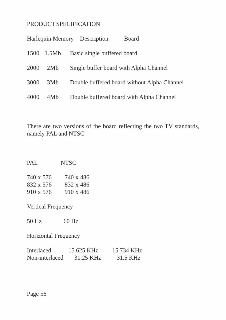
PRODUCT SPECIFICATION
Harlequin Memory Description Board
1500 1.5Mb Basic single buffered board
2000 2Mb Single buffer board with Alpha Channel
3000 3Mb Double buffered board without Alpha Channel
4000 4Mb Double buffered board with Alpha Channel
There are two versions of the board reflecting the two TV standards,namely PAL and NTSC
PAL NTSC
740 x 576 740 x 486832 x 576 832 x 486910 x 576 910 x 486
Vertical Frequency
50 Hz 60 Hz
Horizontal Frequency
Interlaced 15.625 KHz 15.734 KHzNon-interlaced 31.25 KHz 31.5 KHz
Page 56
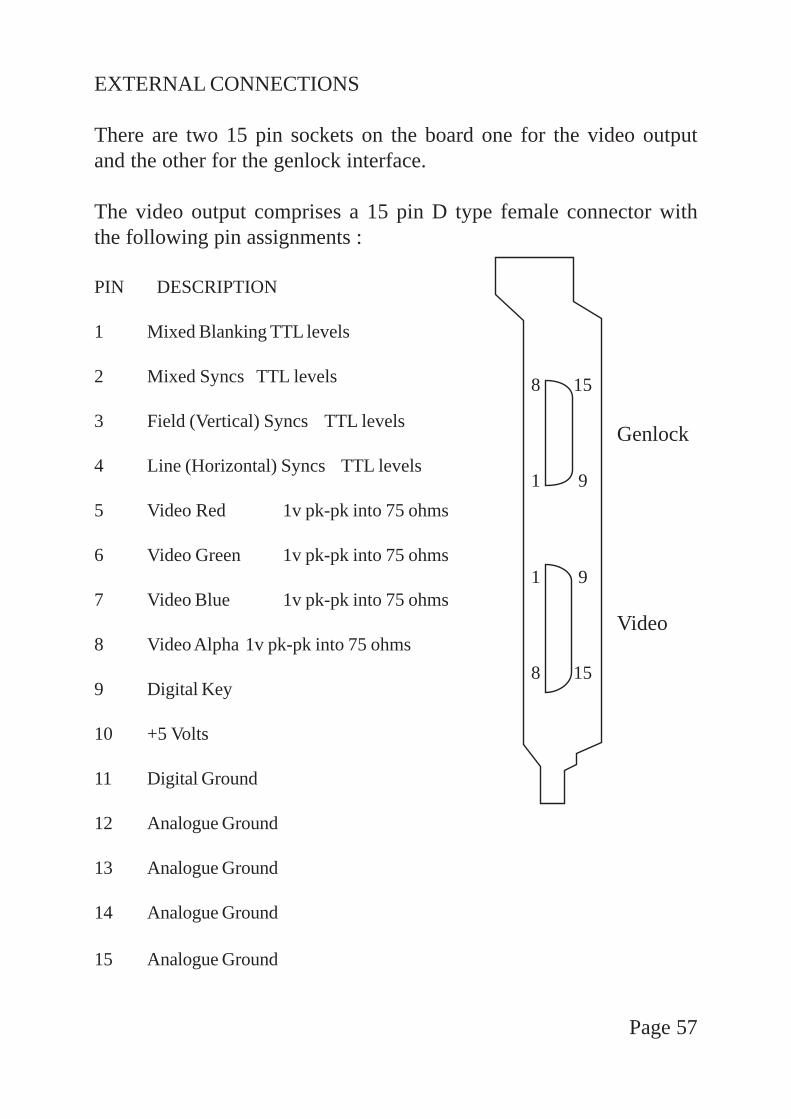
EXTERNAL CONNECTIONS
There are two 15 pin sockets on the board one for the video outputand the other for the genlock interface.
The video output comprises a 15 pin D type female connector withthe following pin assignments :
PIN DESCRIPTION
1 Mixed Blanking TTL levels
2 Mixed Syncs TTL levels
3 Field (Vertical) Syncs TTL levels
4 Line (Horizontal) Syncs TTL levels
5 Video Red 1v pk-pk into 75 ohms
6 Video Green 1v pk-pk into 75 ohms
7 Video Blue 1v pk-pk into 75 ohms
8 Video Alpha 1v pk-pk into 75 ohms
9 Digital Key
10 +5 Volts
11 Digital Ground
12 Analogue Ground
13 Analogue Ground
14 Analogue Ground
15 Analogue Ground
Page 57
8 15
Genlock
1 9
1 9
Video
8 15

The Genlock interface comprises a 15 pin D type male connectorwith the following pin assignments :
PIN DESCRIPTION
1 VMODE02 GROUND3 VMODE14 Ground5 /GPRES6 Ground7 /LSYNC8 Ground9 /FSYNC10 Ground11 /FRST12 Ground13 Ground14 Ground15 GLCLK
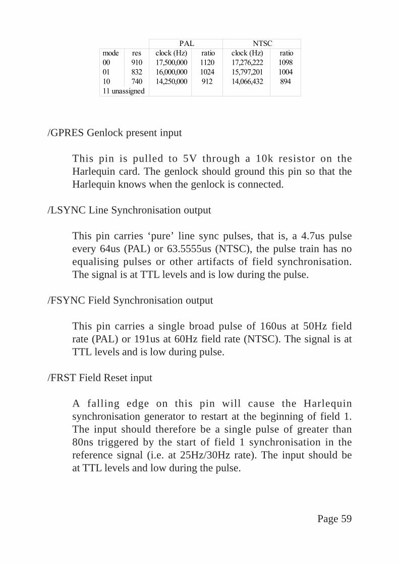
VMODE0, VMODE1 -Video mode select output
These binary coded bits enable the genlock to select its VCOcentre frequency for each video mode. The nominal value isdifferent for each horizontal resolution and between PAL andNTSC. The table below summarises the required values. Thecolumn marked ratio indicates the multiplying factor requiredto generate the nominal master frequency from the nominalline rate (PAL = 15,625Hz, NTSC = 15,734.264Hz).
Page 58
/GPRES Genlock present input
This pin is pulled to 5V through a 10k resistor on theHarlequin card. The genlock should ground this pin so that theHarlequin knows when the genlock is connected.
/LSYNC Line Synchronisation output
This pin carries ‘pure’ line sync pulses, that is, a 4.7us pulseevery 64us (PAL) or 63.5555us (NTSC), the pulse train has noequalising pulses or other artifacts of field synchronisation.The signal is at TTL levels and is low during the pulse.
/FSYNC Field Synchronisation output
This pin carries a single broad pulse of 160us at 50Hz fieldrate (PAL) or 191us at 60Hz field rate (NTSC). The signal is atTTL levels and is low during pulse.
/FRST Field Reset input
A falling edge on this pin will cause the Harlequinsynchronisation generator to restart at the beginning of field 1.The input should therefore be a single pulse of greater than80ns triggered by the start of field 1 synchronisation in thereference signal (i.e. at 25Hz/30Hz rate). The input should beat TTL levels and low during the pulse.
Page 59
GLCLK Genlock Master Clock input
This pin carries the genlocked master clock from which theon-board synchronisation timings are derived. The nominalfrequencies of this input for PAL/NTSC and the varioushorizontal resolutions are given in the table above. The inputshould be at TTL levels and have a niminally 50% mark -space ratio (60% / 40% worst case).
Page 60

Amiga Hardware WorldEverything about Amiga hardware...
~http://amiga.resource.cx