Stay connected: A successful mobile device strategy - ibm.com

IBM 4693, 4694, and 4695 Point-of-Sale Terminals:
Hardware Service Manual
SY27-0337-02
Note
Before using this information and the products it supports, be sure to read the general information under “Notices”on page viii. Translations of the safety notices can be found in IBM 4693/4694 Point of Sale Terminals: ProductSafety Information, P/N 60G1330.
Third Edition (October, 1995)
This is the third edition of the IBM 4693, 4694, 4695 Point-of-Sale Terminals: Hardware Service Manual.
Order publications through your IBM representative or the IBM branch office serving your locality. Publications are not stocked at theaddress given below.
A form for readers’ comments is provided at the back of this publication. If the form has been removed, address your comments to:
IBM Corporation, Information Development, Department CJMAP.O. Box 12195Research Triangle Park, North Carolina 27709
USA
When you send information to IBM, you grant IBM a nonexclusive right to use or distribute the information in any way it believesappropriate without incurring any obligation to you.
Copyright International Business Machines Corporation 1993, 1995. All rights reserved.Note to U.S. Government Users — Documentation related to restricted rights — Use, duplication or disclosure is subject torestrictions set forth in GSA ADP Schedule Contract with IBM Corp.

Contents
Notices . . . . . . . . . . . . . . . . . . . . . . . . . . . . . . . . . . . . . . . . . . . . . . . . . . . . . . . . viiiTrademarks . . . . . . . . . . . . . . . . . . . . . . . . . . . . . . . . . . . . . . . . . . . . . . . . . . . viiiElectronic Emission Notices . . . . . . . . . . . . . . . . . . . . . . . . . . . . . . . . . . . . . . . . . . ixGeneral Safety Considerations . . . . . . . . . . . . . . . . . . . . . . . . . . . . . . . . . . . . . . . . ix
Electrostatic Discharge (ESD) . . . . . . . . . . . . . . . . . . . . . . . . . . . . . . . . . . . . . . . . . . xEuropean Union (EU) Electromagnetic Compatibility . . . . . . . . . . . . . . . . . . . . . . . . . . . . xiLaser Product Identification . . . . . . . . . . . . . . . . . . . . . . . . . . . . . . . . . . . . . . . . . . xi
Preface . . . . . . . . . . . . . . . . . . . . . . . . . . . . . . . . . . . . . . . . . . . . . . . . . . . . . . . xiiStore System Library . . . . . . . . . . . . . . . . . . . . . . . . . . . . . . . . . . . . . . . . . . . . . . . . xiiStore System Related Publications — Software . . . . . . . . . . . . . . . . . . . . . . . . . . . . . . . . xiiiStore System Related Publications — Hardware . . . . . . . . . . . . . . . . . . . . . . . . . . . . . . . . xiii
General Publications . . . . . . . . . . . . . . . . . . . . . . . . . . . . . . . . . . . . . . . . . . . . . . xiiiSummary of Changes . . . . . . . . . . . . . . . . . . . . . . . . . . . . . . . . . . . . . . . . . . . . . . . xiv
Chapter 1. Start Here for 4693 Problems . . . . . . . . . . . . . . . . . . . . . . . . . . . . . . . . . 1-14693 Problem Determination . . . . . . . . . . . . . . . . . . . . . . . . . . . . . . . . . . . . . . . . . . 1-2
MAP 0100: General Checkout . . . . . . . . . . . . . . . . . . . . . . . . . . . . . . . . . . . . . . . 1-3MAP 0110: Input/Output (I/O) Device Isolation . . . . . . . . . . . . . . . . . . . . . . . . . . . . . . 1-6
4693 Messages . . . . . . . . . . . . . . . . . . . . . . . . . . . . . . . . . . . . . . . . . . . . . . . . . . 1-8How To Read 4693 Power-On Self-Test (POST) Messages . . . . . . . . . . . . . . . . . . . . . . 1-9How To Retrieve Network Remote Program Load (RPL) Messages . . . . . . . . . . . . . . . . . . 1-9Power-On Self-Test Message Index . . . . . . . . . . . . . . . . . . . . . . . . . . . . . . . . . . . 1-104693 Power-On Self-Test Messages . . . . . . . . . . . . . . . . . . . . . . . . . . . . . . . . . . . 1-11Ethernet Messages . . . . . . . . . . . . . . . . . . . . . . . . . . . . . . . . . . . . . . . . . . . . . 1-25PC Network Messages . . . . . . . . . . . . . . . . . . . . . . . . . . . . . . . . . . . . . . . . . . . 1-26Token-Ring Messages . . . . . . . . . . . . . . . . . . . . . . . . . . . . . . . . . . . . . . . . . . . 1-2863nn Messages . . . . . . . . . . . . . . . . . . . . . . . . . . . . . . . . . . . . . . . . . . . . . . . 1-31Application Program Status xxx* . . . . . . . . . . . . . . . . . . . . . . . . . . . . . . . . . . . . . 1-34Annn through Lnnn and Nnnn through Snnn Messages . . . . . . . . . . . . . . . . . . . . . . . . 1-34Mnnnn Messages . . . . . . . . . . . . . . . . . . . . . . . . . . . . . . . . . . . . . . . . . . . . . . 1-35Tnnnn Messages . . . . . . . . . . . . . . . . . . . . . . . . . . . . . . . . . . . . . . . . . . . . . . 1-39Unnn Messages . . . . . . . . . . . . . . . . . . . . . . . . . . . . . . . . . . . . . . . . . . . . . . . 1-45Wnnn Messages . . . . . . . . . . . . . . . . . . . . . . . . . . . . . . . . . . . . . . . . . . . . . . . 1-46Xnnn Messages . . . . . . . . . . . . . . . . . . . . . . . . . . . . . . . . . . . . . . . . . . . . . . . 1-46Ynnn Messages . . . . . . . . . . . . . . . . . . . . . . . . . . . . . . . . . . . . . . . . . . . . . . . 1-46Znnn Messages . . . . . . . . . . . . . . . . . . . . . . . . . . . . . . . . . . . . . . . . . . . . . . . 1-46
4693 Symptoms . . . . . . . . . . . . . . . . . . . . . . . . . . . . . . . . . . . . . . . . . . . . . . . . 1-474693 Power-On Self-Test (POST) Beep Symptoms . . . . . . . . . . . . . . . . . . . . . . . . . . 1-48
Problems with 4693 Models 3W1 and 741 Service Level Update . . . . . . . . . . . . . . . . . . . . 1-49Input/Output Device Symptoms . . . . . . . . . . . . . . . . . . . . . . . . . . . . . . . . . . . . . . 1-504693 Operator Panel Indicators and Switches . . . . . . . . . . . . . . . . . . . . . . . . . . . . . 1-51Option Adapter Symptoms . . . . . . . . . . . . . . . . . . . . . . . . . . . . . . . . . . . . . . . . . 1-544693 Programmable Power Control Symptoms . . . . . . . . . . . . . . . . . . . . . . . . . . . . . 1-55Fixed Disk Symptoms . . . . . . . . . . . . . . . . . . . . . . . . . . . . . . . . . . . . . . . . . . . . 1-55Diskette Drive Symptoms . . . . . . . . . . . . . . . . . . . . . . . . . . . . . . . . . . . . . . . . . 1-56Network Communications Symptoms . . . . . . . . . . . . . . . . . . . . . . . . . . . . . . . . . . . 1-57Ethernet Network . . . . . . . . . . . . . . . . . . . . . . . . . . . . . . . . . . . . . . . . . . . . . . 1-57PC Network Baseband . . . . . . . . . . . . . . . . . . . . . . . . . . . . . . . . . . . . . . . . . . . 1-58Token-Ring Network . . . . . . . . . . . . . . . . . . . . . . . . . . . . . . . . . . . . . . . . . . . . 1-58Store Loop Communications Symptoms . . . . . . . . . . . . . . . . . . . . . . . . . . . . . . . . . 1-59
Copyright IBM Corp. 1993, 1995 iii
Storage Retention Symptoms . . . . . . . . . . . . . . . . . . . . . . . . . . . . . . . . . . . . . . . 1-60RS232 Serial Device Symptoms . . . . . . . . . . . . . . . . . . . . . . . . . . . . . . . . . . . . . 1-60Video Display Symptoms . . . . . . . . . . . . . . . . . . . . . . . . . . . . . . . . . . . . . . . . . . 1-61Miscellaneous Symptoms . . . . . . . . . . . . . . . . . . . . . . . . . . . . . . . . . . . . . . . . . 1-62
4693 Configuration, Tests, and Utilities . . . . . . . . . . . . . . . . . . . . . . . . . . . . . . . . . . . 1-64Keyboard Differences . . . . . . . . . . . . . . . . . . . . . . . . . . . . . . . . . . . . . . . . . . . . 1-65Reference, Diagnostic, and Support Diskettes . . . . . . . . . . . . . . . . . . . . . . . . . . . . . 1-65System Partition . . . . . . . . . . . . . . . . . . . . . . . . . . . . . . . . . . . . . . . . . . . . . . . 1-65IML Image . . . . . . . . . . . . . . . . . . . . . . . . . . . . . . . . . . . . . . . . . . . . . . . . . . 1-66Test Programs Summary . . . . . . . . . . . . . . . . . . . . . . . . . . . . . . . . . . . . . . . . . . 1-67Power-On Self-Test (POST) . . . . . . . . . . . . . . . . . . . . . . . . . . . . . . . . . . . . . . . . 1-67Configuration Programs Summary . . . . . . . . . . . . . . . . . . . . . . . . . . . . . . . . . . . . 1-68Utility Programs Summary . . . . . . . . . . . . . . . . . . . . . . . . . . . . . . . . . . . . . . . . . 1-69Loading the System Programs . . . . . . . . . . . . . . . . . . . . . . . . . . . . . . . . . . . . . . 1-71Flow of 4693 System Programs Menus . . . . . . . . . . . . . . . . . . . . . . . . . . . . . . . . . 1-73Flow of 4693-3W1 System Programs Menus . . . . . . . . . . . . . . . . . . . . . . . . . . . . . . 1-74Test Procedure Using System Programs . . . . . . . . . . . . . . . . . . . . . . . . . . . . . . . . 1-75Testing Procedure Using Operating System Exercisers . . . . . . . . . . . . . . . . . . . . . . . . 1-75Configuration Procedure Using System Programs . . . . . . . . . . . . . . . . . . . . . . . . . . . 1-75Utilities Procedure Using System Programs . . . . . . . . . . . . . . . . . . . . . . . . . . . . . . . 1-75Resetting Configuration and the Terminal Load . . . . . . . . . . . . . . . . . . . . . . . . . . . . . 1-76
4693 Removals and Replacements . . . . . . . . . . . . . . . . . . . . . . . . . . . . . . . . . . . . . 1-77Electrostatic Discharge (ESD) . . . . . . . . . . . . . . . . . . . . . . . . . . . . . . . . . . . . . . . 1-78Removing and Replacing the Front Panel . . . . . . . . . . . . . . . . . . . . . . . . . . . . . . . . 1-79Removing and Replacing the Storage Retention Battery Pack . . . . . . . . . . . . . . . . . . . . 1-80Removing and Replacing the Operator Panel Assembly . . . . . . . . . . . . . . . . . . . . . . . . 1-80Removing and Replacing the Power Supply . . . . . . . . . . . . . . . . . . . . . . . . . . . . . . . 1-81Removing and Replacing the Diskette Drive . . . . . . . . . . . . . . . . . . . . . . . . . . . . . . . 1-82Removing and Replacing the Cooling Fan and Plenum . . . . . . . . . . . . . . . . . . . . . . . . 1-82Removing and Replacing the Logic Tray . . . . . . . . . . . . . . . . . . . . . . . . . . . . . . . . . 1-83Removing and Replacing the Fixed Disk Drive . . . . . . . . . . . . . . . . . . . . . . . . . . . . . 1-84Removing and Replacing an Option Adapter . . . . . . . . . . . . . . . . . . . . . . . . . . . . . . 1-85Removing and Replacing Memory Modules . . . . . . . . . . . . . . . . . . . . . . . . . . . . . . . 1-85Removing and Replacing the Terminal System Board . . . . . . . . . . . . . . . . . . . . . . . . . 1-86Removing and Replacing the Speaker . . . . . . . . . . . . . . . . . . . . . . . . . . . . . . . . . . 1-86Removing and Replacing the Rear Cover . . . . . . . . . . . . . . . . . . . . . . . . . . . . . . . . 1-86Removing and Replacing the Rear Connector Panel . . . . . . . . . . . . . . . . . . . . . . . . . . 1-87Removing and Replacing the Input/Output Devices . . . . . . . . . . . . . . . . . . . . . . . . . . 1-88Removing and Replacing the Top Cover . . . . . . . . . . . . . . . . . . . . . . . . . . . . . . . . . 1-89Removing and Replacing the Side Covers . . . . . . . . . . . . . . . . . . . . . . . . . . . . . . . . 1-89Removing and Replacing the Keylock Insert . . . . . . . . . . . . . . . . . . . . . . . . . . . . . . 1-90Removing and Replacing the Blank Keylock Insert . . . . . . . . . . . . . . . . . . . . . . . . . . . 1-90Removing the Power-On Password . . . . . . . . . . . . . . . . . . . . . . . . . . . . . . . . . . . . 1-91Removing and Replacing an Extended Duration Battery . . . . . . . . . . . . . . . . . . . . . . . . 1-92
4693 Model 741 Processor Jumper Information . . . . . . . . . . . . . . . . . . . . . . . . . . . . . . 1-93Removing the Power-On Password . . . . . . . . . . . . . . . . . . . . . . . . . . . . . . . . . . . . . 1-94
Chapter 2. Start Here for 4694 Problems . . . . . . . . . . . . . . . . . . . . . . . . . . . . . . . . . 2-14694 Problem Determination . . . . . . . . . . . . . . . . . . . . . . . . . . . . . . . . . . . . . . . . . . 2-2
Preliminary Checklist . . . . . . . . . . . . . . . . . . . . . . . . . . . . . . . . . . . . . . . . . . . . . 2-24694 Symptom Table . . . . . . . . . . . . . . . . . . . . . . . . . . . . . . . . . . . . . . . . . . . . . . 2-3POST/Beep Messages . . . . . . . . . . . . . . . . . . . . . . . . . . . . . . . . . . . . . . . . . . . . . . 2-5Testing the 4694 . . . . . . . . . . . . . . . . . . . . . . . . . . . . . . . . . . . . . . . . . . . . . . . . . 2-8
Service Diskette Menus . . . . . . . . . . . . . . . . . . . . . . . . . . . . . . . . . . . . . . . . . . . 2-8
iv 4693, 4694, and 4695 Hardware Service Manual

Point-of-Sale Device Tests . . . . . . . . . . . . . . . . . . . . . . . . . . . . . . . . . . . . . . . . . . 2-9System Unit Tests . . . . . . . . . . . . . . . . . . . . . . . . . . . . . . . . . . . . . . . . . . . . . . . 2-9Utilities . . . . . . . . . . . . . . . . . . . . . . . . . . . . . . . . . . . . . . . . . . . . . . . . . . . . . 2-9Viewing Configuration . . . . . . . . . . . . . . . . . . . . . . . . . . . . . . . . . . . . . . . . . . . . . 2-9System Configuration Menus . . . . . . . . . . . . . . . . . . . . . . . . . . . . . . . . . . . . . . . 2-10
4694 Models 001, 004, and 024 Removals and Replacements . . . . . . . . . . . . . . . . . . . . . 2-11Electrostatic Discharge (ESD) . . . . . . . . . . . . . . . . . . . . . . . . . . . . . . . . . . . . . . . 2-11Removing and Replacing the Covers . . . . . . . . . . . . . . . . . . . . . . . . . . . . . . . . . . . 2-12Removing and Replacing the Diskette Drive or Fixed Disk Drive . . . . . . . . . . . . . . . . . . . 2-13Removing and Replacing the VGA Card . . . . . . . . . . . . . . . . . . . . . . . . . . . . . . . . . 2-13Removing and Replacing the Power Supply . . . . . . . . . . . . . . . . . . . . . . . . . . . . . . . 2-14Removing and Replacing the Riser Card and PCMCIA Card . . . . . . . . . . . . . . . . . . . . . 2-14Removing and Replacing the System Board . . . . . . . . . . . . . . . . . . . . . . . . . . . . . . 2-15Removing and Replacing Memory Modules . . . . . . . . . . . . . . . . . . . . . . . . . . . . . . . 2-16
4694 Models 041, 044, and 144 Removals and Replacements . . . . . . . . . . . . . . . . . . . . . 2-17Removing and Replacing the Front Panel and Logic Tray . . . . . . . . . . . . . . . . . . . . . . . 2-17Removing and Replacing the Diskette Drive or Fixed Disk Drive . . . . . . . . . . . . . . . . . . . 2-18Removing and Replacing the Power Supply . . . . . . . . . . . . . . . . . . . . . . . . . . . . . . . 2-19Removing and Replacing the Riser Card and PCMCIA Card . . . . . . . . . . . . . . . . . . . . . 2-20Removing and Replacing the System Board . . . . . . . . . . . . . . . . . . . . . . . . . . . . . . 2-20Removing and Replacing Memory Modules . . . . . . . . . . . . . . . . . . . . . . . . . . . . . . . 2-20
Chapter 3. Start Here for 4695 Problems . . . . . . . . . . . . . . . . . . . . . . . . . . . . . . . . . 3-14695 Service Diskette Introduction . . . . . . . . . . . . . . . . . . . . . . . . . . . . . . . . . . . . . . . 3-2
Main Menu . . . . . . . . . . . . . . . . . . . . . . . . . . . . . . . . . . . . . . . . . . . . . . . . . . . 3-34695 Service Level Update Procedure . . . . . . . . . . . . . . . . . . . . . . . . . . . . . . . . . . . . 3-4
Removing the Power-On Password . . . . . . . . . . . . . . . . . . . . . . . . . . . . . . . . . . . . . 3-4Problem Determination – 4695 Models 002 and 012 . . . . . . . . . . . . . . . . . . . . . . . . . . . . 3-5
Preliminary Checklist . . . . . . . . . . . . . . . . . . . . . . . . . . . . . . . . . . . . . . . . . . . . . 3-5Symptom Table – 4695 Models 002 and 012 . . . . . . . . . . . . . . . . . . . . . . . . . . . . . . . . . 3-6Setting the 4695 Point of Sale Adapter Switches (Model 002 and 012) . . . . . . . . . . . . . . . . . 3-94695 Models 002 and 012 Removals and Replacements . . . . . . . . . . . . . . . . . . . . . . . . . 3-10
Removing and Replacing the Tablet FRUs . . . . . . . . . . . . . . . . . . . . . . . . . . . . . . . 3-10Removing and Replacing the Digital Interface Cable . . . . . . . . . . . . . . . . . . . . . . . . . . 3-12Removing and Replacing the Clutch . . . . . . . . . . . . . . . . . . . . . . . . . . . . . . . . . . . 3-12Removing the 4695 from the Counter . . . . . . . . . . . . . . . . . . . . . . . . . . . . . . . . . . 3-13Closing the Rear Door . . . . . . . . . . . . . . . . . . . . . . . . . . . . . . . . . . . . . . . . . . . 3-134695 Models 002 and 012 Connector Panel . . . . . . . . . . . . . . . . . . . . . . . . . . . . . . . 3-13Removing and Replacing the Interface Card and Shield . . . . . . . . . . . . . . . . . . . . . . . . 3-14Removing and Replacing the Pedestal Stand . . . . . . . . . . . . . . . . . . . . . . . . . . . . . . 3-14Removing and Replacing the Rear Door . . . . . . . . . . . . . . . . . . . . . . . . . . . . . . . . . 3-15Removing and Replacing the Customer Display . . . . . . . . . . . . . . . . . . . . . . . . . . . . 3-16Removing, Replacing, and Cleaning the Customer Display Lens . . . . . . . . . . . . . . . . . . . 3-16Removing and Replacing the MSR . . . . . . . . . . . . . . . . . . . . . . . . . . . . . . . . . . . . 3-17
Problem Determination – 4695 Models 201 and 211 . . . . . . . . . . . . . . . . . . . . . . . . . . . 3-18Preliminary Checklist . . . . . . . . . . . . . . . . . . . . . . . . . . . . . . . . . . . . . . . . . . . . 3-18
Symptom Table – 4695 Models 201 and 211 . . . . . . . . . . . . . . . . . . . . . . . . . . . . . . . . 3-19Models 201 and 211 . . . . . . . . . . . . . . . . . . . . . . . . . . . . . . . . . . . . . . . . . . . . . . 3-21
POST Messages – Models 201 and 211 . . . . . . . . . . . . . . . . . . . . . . . . . . . . . . . . . 3-21POST Beep Codes – 4695 Models 201 and 211 . . . . . . . . . . . . . . . . . . . . . . . . . . . . 3-26Run-time Error Messages – 4695 Models 201 and 211 . . . . . . . . . . . . . . . . . . . . . . . . 3-27Test Error Messages – 4695 Models 201 and 211 . . . . . . . . . . . . . . . . . . . . . . . . . . . 3-28Service Diskette Messages – Models 201 and 211 . . . . . . . . . . . . . . . . . . . . . . . . . . . 3-32Rear Connector Panel – 4695 Models 201 and 211 . . . . . . . . . . . . . . . . . . . . . . . . . . 3-34
Contents v

Front Panel – 4695 Models 201 and 211 . . . . . . . . . . . . . . . . . . . . . . . . . . . . . . . . 3-34Removals and Replacements – 4695 Models 201 and 211 . . . . . . . . . . . . . . . . . . . . . . . 3-35
Removing and Replacing the Tablet . . . . . . . . . . . . . . . . . . . . . . . . . . . . . . . . . . . 3-35Removing and Replacing the MSR or MSR Blanks . . . . . . . . . . . . . . . . . . . . . . . . . . 3-36Removing and Replacing the Tablet FRUs . . . . . . . . . . . . . . . . . . . . . . . . . . . . . . . 3-36
Removing and Replacing the 4695 LCD Backlight (10.4 in.) . . . . . . . . . . . . . . . . . . . . . . 3-38Removing and Replacing the Top Cover . . . . . . . . . . . . . . . . . . . . . . . . . . . . . . . . . 3-39Removing and Replacing Memory Modules . . . . . . . . . . . . . . . . . . . . . . . . . . . . . . . 3-40Removing and Replacing the Fixed Disk . . . . . . . . . . . . . . . . . . . . . . . . . . . . . . . . . 3-40Removing and Replacing the Diskette Drive . . . . . . . . . . . . . . . . . . . . . . . . . . . . . . . 3-41Removing and Replacing the Front Panel . . . . . . . . . . . . . . . . . . . . . . . . . . . . . . . . 3-41Removing and Replacing the System Board . . . . . . . . . . . . . . . . . . . . . . . . . . . . . . 3-42Removing and Replacing the Processor . . . . . . . . . . . . . . . . . . . . . . . . . . . . . . . . . 3-42Removing and Replacing the Video RAM . . . . . . . . . . . . . . . . . . . . . . . . . . . . . . . . 3-43Installing the Expansion Feature . . . . . . . . . . . . . . . . . . . . . . . . . . . . . . . . . . . . . 3-44Jumper Information . . . . . . . . . . . . . . . . . . . . . . . . . . . . . . . . . . . . . . . . . . . . . 3-45Removing and Replacing the Power Button . . . . . . . . . . . . . . . . . . . . . . . . . . . . . . . 3-47Removing and Replacing the Lock Assembly FRUs . . . . . . . . . . . . . . . . . . . . . . . . . . 3-48Removing and Replacing a Lock Insert . . . . . . . . . . . . . . . . . . . . . . . . . . . . . . . . . 3-49Removing and Replacing a Blank Lock Insert . . . . . . . . . . . . . . . . . . . . . . . . . . . . . . 3-50Removing and Replacing the Upper Wedge . . . . . . . . . . . . . . . . . . . . . . . . . . . . . . . 3-50Removing and Replacing the Tablet Latch . . . . . . . . . . . . . . . . . . . . . . . . . . . . . . . 3-51Removing and Replacing the Lower Wedge Shaft Assembly . . . . . . . . . . . . . . . . . . . . . 3-51Removing and Replacing the Front Door . . . . . . . . . . . . . . . . . . . . . . . . . . . . . . . . 3-52Removing and Replacing the Rear Door . . . . . . . . . . . . . . . . . . . . . . . . . . . . . . . . . 3-52Removing and Replacing the Customer Display . . . . . . . . . . . . . . . . . . . . . . . . . . . . 3-52Removing, Replacing, and Cleaning the Customer Display Lens . . . . . . . . . . . . . . . . . . . 3-53Removing and Replacing the Lithium Battery . . . . . . . . . . . . . . . . . . . . . . . . . . . . . . 3-53Removing and Replacing The PCMCIA Feature . . . . . . . . . . . . . . . . . . . . . . . . . . . . 3-54
Running Setup – 4695 Models 201 and 211 . . . . . . . . . . . . . . . . . . . . . . . . . . . . . . . . 3-554695 Setup Diskette . . . . . . . . . . . . . . . . . . . . . . . . . . . . . . . . . . . . . . . . . . . . . . 3-56
Creating A Setup Diskette . . . . . . . . . . . . . . . . . . . . . . . . . . . . . . . . . . . . . . . . . 3-56Using the Setup Diskette . . . . . . . . . . . . . . . . . . . . . . . . . . . . . . . . . . . . . . . . . . 3-57
Appendix A. 4693 Hardware Overview . . . . . . . . . . . . . . . . . . . . . . . . . . . . . . . . . . . A-1Front and Rear Views of the IBM 4693 . . . . . . . . . . . . . . . . . . . . . . . . . . . . . . . . . . A-2Sockets and Devices . . . . . . . . . . . . . . . . . . . . . . . . . . . . . . . . . . . . . . . . . . . . . A-3Rear Connector Panels . . . . . . . . . . . . . . . . . . . . . . . . . . . . . . . . . . . . . . . . . . . . A-4Description of 4693 Power Modes . . . . . . . . . . . . . . . . . . . . . . . . . . . . . . . . . . . . . A-5
Appendix B. Maintenance Inspection for the 4693 . . . . . . . . . . . . . . . . . . . . . . . . . . . B-1
Appendix C. Preventive Maintenance . . . . . . . . . . . . . . . . . . . . . . . . . . . . . . . . . . . C-14693 Preventive Maintenance Procedures . . . . . . . . . . . . . . . . . . . . . . . . . . . . . . . . . . C-3
System Unit . . . . . . . . . . . . . . . . . . . . . . . . . . . . . . . . . . . . . . . . . . . . . . . . . . C-3Cash Drawer . . . . . . . . . . . . . . . . . . . . . . . . . . . . . . . . . . . . . . . . . . . . . . . . . . C-3Display . . . . . . . . . . . . . . . . . . . . . . . . . . . . . . . . . . . . . . . . . . . . . . . . . . . . . C-3Keyboard . . . . . . . . . . . . . . . . . . . . . . . . . . . . . . . . . . . . . . . . . . . . . . . . . . . . C-3Keylocks . . . . . . . . . . . . . . . . . . . . . . . . . . . . . . . . . . . . . . . . . . . . . . . . . . . . C-3Scanners . . . . . . . . . . . . . . . . . . . . . . . . . . . . . . . . . . . . . . . . . . . . . . . . . . . . C-3Model 1 or 2 Printer . . . . . . . . . . . . . . . . . . . . . . . . . . . . . . . . . . . . . . . . . . . . . . C-3Model 3 or 4 Printer . . . . . . . . . . . . . . . . . . . . . . . . . . . . . . . . . . . . . . . . . . . . . . C-4
Appendix D. Special Tools . . . . . . . . . . . . . . . . . . . . . . . . . . . . . . . . . . . . . . . . . . D-1
vi 4693, 4694, and 4695 Hardware Service Manual

Expendable Supplies . . . . . . . . . . . . . . . . . . . . . . . . . . . . . . . . . . . . . . . . . . . . . D-1
Appendix E. Collecting Vital Product Data for the 4693 . . . . . . . . . . . . . . . . . . . . . . . . E-1Entering Vital Product Data Using the Reference Diskette . . . . . . . . . . . . . . . . . . . . . . . . . E-1Printing Vital Product Data Using the Reference Diskette . . . . . . . . . . . . . . . . . . . . . . . . . E-4
Appendix F. IBM Wireless LAN Return Codes . . . . . . . . . . . . . . . . . . . . . . . . . . . . . . F-1Novell RPL ROM Error Messages . . . . . . . . . . . . . . . . . . . . . . . . . . . . . . . . . . . . . F-2
Index . . . . . . . . . . . . . . . . . . . . . . . . . . . . . . . . . . . . . . . . . . . . . . . . . . . . . . . . X-1
Contents vii

Notices
The following paragraph does not apply to the United Kingdom or any country where such provisions areinconsistent with local law: INTERNATIONAL BUSINESS MACHINES CORPORATION PROVIDES THISPUBLICATION "AS IS" WITHOUT WARRANTY OF ANY KIND, EITHER EXPRESS OR IMPLIED,INCLUDING, BUT NOT LIMITED TO THE IMPLIED WARRANTIES OF MERCHANTABILITY ORFITNESS FOR A PARTICULAR PURPOSE. Some states do not allow disclaimer of express or impliedwarranties in certain transactions, therefore, this statement may not apply to you.
References in this publication to IBM products, programs, or services do not imply that IBM intends tomake these available in all countries in which IBM operates. Any reference to an IBM product, program,or service is not intended to state or imply that only IBM’s product, program, or service may be used. Anyfunctionally equivalent product, program, or service that does not infringe any of IBM’s intellectual propertyrights may be used instead of the IBM product, program, or service. Evaluation and verification ofoperation in conjunction with other products, except those expressly designated by IBM, are the user’sresponsibility.
IBM may have patents or pending patent applications covering subject matter in this document. Thefurnishing of this document does not give you any license to these patents. You can send licenseinquiries, in writing, to the IBM Director of Licensing, IBM Corporation, 500 Columbus Avenue, Thornwood,NY 10594 USA.
Trademarks
The following terms used in this publication are trademarks of the IBM Corporation in the United States ofAmerica or other countries or both:
Windows is a trademark of Microsoft Corporation.
PC Direct is a trademark of Ziff Communications Company and is used by IBM Corporation under license.
UNIX is a registered trademark in the United States and other countries licensed exclusively throughX/Open Company Limited.
Other company, product, and service names, which may be denoted by a double asterisk (**), may betrademarks or service marks of others.
IBM Micro Channel Sure Point Touch Screen
viii 4693, 4694, and 4695 Hardware Service Manual

Electronic Emission Notices
Federal Communications Commission (FCC) StatementNote: This equipment has been tested and found to comply with the limits for a Class A digital device,pursuant to Part 15 of the FCC Rules. These limits are designed to provide reasonable protection againstharmful interference when the equipment is operated in a commercial environment. This equipmentgenerates, uses, and can radiate radio frequency energy and, if not installed and used in accordance withthe instruction manual, may cause harmful interference to radio communications. Operation of thisequipment in a residential area is likely to cause harmful interference, in which case the user will berequired to correct the interference at his own expense.
Properly shielded and grounded cables and connectors must be used in order to meet FCC emissionlimits. IBM is not responsible for any radio or television interference caused by using other thanrecommended cables and connectors or by unauthorized changes or modifications to this equipment.Unauthorized changes or modifications could void the user's authority to operate the equipment.
This device complies with Part 15 of the FCC Rules. Operation is subject to the following two conditions:(1) this device may not cause harmful interference, and (2) this device must accept any interferencereceived, including interference that may cause undesired operation.
Canada ICES – Class A:
This class A digital apparatus meets the requirements of the Canadian Interference-Causing EquipmentRegulations.
Cet appareil numérique de la classe A respecte toutes les exigences du Réglement sur le matérielbrouilleur du Canada.
United Kingdom Office of Telecommunications Statement of Compliance:
The United Kingdom Telecommunications Act 1984. This apparatus is approved under numberNS/G/1234/J/100003 for indirect connections to the public telecommunications systems in the UnitedKingdom.
General Safety Considerations
The following general safety considerations should be observed whenever you work with electricity or withany electronic equipment.
DANGER
Never work on equipment or connect or disconnect signal cables during periods oflightning activity.
CAUTION:For your safety, connect equipment requiring electrical power to a properly wired and groundedoutlet.
The following general safety considerations should be observed whenever you work with a point-of-saleprinter.
Contents ix

CAUTION:For safety when running the printer test, make sure personal articles such as ties, necklaces, orbracelets do not get caught in the moving print head.
The following general consideration should be observed whenever you exchange batteries in apoint-of-sale terminal.
Replaceable Lithium Battery inside system unit.
Non-replaceable Lithium Battery inside adapter.
Nickel-Cadmium Batteries:
Some Point-of-Sale products contain a nickel-cadmium battery. The battery must be recycled or disposedof properly. Recycling facilities may not be available in your area.
In the United States of America, IBM has established a collection process for reuse, recycling, or properdisposal of used IBM nickel-cadmium batteries and battery packs. For information on proper disposal ofthe nickel-cadmium batteries in this product, please contact IBM at 1-800-426-4333. Please have the IBMpart listed on the battery available prior to your call.
For information on disposal of nickel-cadmium batteries outside the United States, contact your local wastedisposal facility.
Electrostatic Discharge (ESD)
Attention ESD damage can occur when there is a difference in charge between the part, the product, andthe service person. No damage will occur if the service person and the part being installed are at thesame charge level.
ESD Damage Prevention
Anytime a service action involves physical contact with logic cards, modules, back-panel pins, or otherESD sensitive (ESDS) parts, the service person must be connected to an ESD common ground point onthe product through the ESD wrist strap and cord.
The ESD ground clip can be attached to any frame ground, ground braid, green wire ground, or the roundground prong on the AC power plug. Coax or connector outside shells can also be used.
Handling Removed Cards
Logic cards removed from a product should be placed in ESD protective containers. No other objectshould be allowed inside the ESD container with the logic card. Attach tags or reports that mustaccompany the card to the outside of the container.
x 4693, 4694, and 4695 Hardware Service Manual

European Union (EU) Electromagnetic Compatibility
This product is in conformity with the protection requirements of EC Council Directive 89/336/EEC on theapproximation of the laws of the Member States relating to electromagnetic compatibility. IBM cannotaccept responsibility for any failure to satisfy the protection requirements resulting from anon-recommended modification of the product, including the fitting of non-IBM option cards.
This product has been tested and found to comply with the limits for Class A Information TechnologyEquipment according to CISPR 22 / European Standard EN 55022. The limits for Class A equipmentwere derived for commercial and industrial environments to provide reasonable protection againstinterference with licensed communication equipment.
Attention This is a Class A product. In a domestic environment this product may cause radio interferencein which case the user may be required to take adequate measures.
Dieses Gerät erfüllt die Bedingungen der EN 55022 Klasse A. Für diese Klasse von Geräten gilt folgendeBestimmung nach dem EMVG: Geräte dürfen an Orten, für die sie nicht ausreichend entstört sind, nur mitbesonderer Genchmigung des Bundesminesters für Post und Telekommunikation oder des Bundesamtesfür Post und Telekommunikation betrieben werden. DieGenchmigung wird erteilt, wenn keineelektromagnetischen Störungen zu erwarten sind. (Auszug aus dem EMVG vom 9.Nov.92, Para.3, Abs.4)
Hinweis:Dieses Genehmigungsverfahren ist von der Deutschen Bundespost noch nicht veröffentlicht worden.
Laser Product Identification
IBM Point of Sale Scanners and the IBM 1520 Hand-Held Scanner are laser products. Where required,the scanner has a label that identifies its classification. The information on the label in the U.S.A. isshown below.
Class II Laser Product -Avoid Long-TermViewing of Direct Light
Contents xi

Preface
This manual is the starting place for HARDWARE problem determination and repair of the IBM 4693,4694, and 4695 Point of Sale Terminals.
The service personnel using this manual should be:
� Trained to service IBM point-of-sale terminals� Trained to service IBM Personal Computers and Personal Systems.
Chapter 1, Start Here for 4693 ProblemsChapter 2, Start Here for 4694 ProblemsChapter 3, Start Here for 4695 Problems
Store System Library
IBM Point of Sale TerminalsIBM 4693 Point of Sale Terminals: Installation and Operation Guide, SA27-3978IBM 4694 Point of Sale Terminals: Installation and Operation Guide, SA27-4005IBM 4695 Point of Sale Terminals: Installation and Operation Guide, GA27-4031IBM 4693 Point of Sale Terminals: Quick Reference Card, P/N 73G1022IBM 4693, 4694, and 4695 Point of Sale Terminals: Maintenance and Test Summary, SX27-3919IBM Store Systems: Hardware Service Manual for Point-of-Sale Input/Output Devices, SY27-0339IBM Store Systems: Installation and Operation Guide for Point-of-Sale Input/Output Devices, GA27-4028IBM Store Systems Adapters: Installation and Problem Determination, GA27-4009IBM Store Systems: Supplement for Point of Sale Terminals - Installation, Operation, and Service,GA27-4035IBM Store Systems: Parts Catalog, S131-0097IBM 4693 Point of Sale Terminals: Reference Diskette, SX27-3918IBM 4693 Point of Sale Terminals: Diagnostic Diskette, SX27-3928IBM 4693 Point of Sale Terminals: Support Diskette for Medialess Terminals, SX27-3929IBM 4694 Point of Sale Terminals Service Diskette, SX27-3933IBM 4695 Point of Sale Terminals Service Diskette, SX27-3965IBM 4693/4694 Point of Sale Terminals Supplemental Drivers, SX27-3934IBM 4695 Point of Sale Touch Terminals: Model 002, 012, 201, and 211 Installation and Operation Guide,GA27-4031
IBM 4690 Store System LibraryIBM 4690 Store System: Planning, Installation, and Configuration Guide – SC30-3600IBM 4690 Store System: Programming Guide – SC30-3602IBM 4690 Store System: User's Guide – SC30-3597IBM 4690 Store System: Communications Programming Reference – SC30-3582IBM 4690 Store System: Messages Guide – SC30-3598.IBM Point of Sale Subsystem for OS/2: Programming Reference and User's Guide, SC30-3560IBM Point of Sale Subsystem for DOS: Programming Reference, SC30-3621
xii 4693, 4694, and 4695 Hardware Service Manual

Store System Related Publications — Software
NetworksIBM Local Area Network Support Program, P/N 83X7873IBM PC Network Baseband Planning Guide, S68X-2269IBM PC Network Broadband Guide, S68X-2268IBM Token-Ring Network Introduction and Planning Guide, GA27-3677
Store System Related Publications — Hardware
ScannersIBM 1520 Hand-Held Scanner User’s Guide, GA27-3685IBM 4684 Store Loop Adapter/A: Installation, Testing, Problem Determination,
and Technical Reference, SD21-0045IBM 4686 Retail Point of Sale Scanner: Physical Planning, Installation, and Operation Guide, SA27-3854IBM 4686 Retail Point of Sale Scanner: Maintenance Manual, SY27-0319IBM 4687 Point of Sale Scanner Model 1: Physical Planning, Installation, and Operation Guide,SA27-3855IBM 4687 Point of Sale Scanner Model 1: Maintenance Manual, SY27-0317IBM 4687 Point of Sale Scanner Model 2: Physical Planning Guide, SA27-3882IBM 4687 Point of Sale Scanner Model 2: Operator’s Guide, SA27-3884IBM 4687 Point of Sale Scanner Model 2: Maintenance Manual, SY27-0324IBM 4696 Point of Sale Scanner Scale: Physical Planning, Installation, and Operation Guide, GA27-3965IBM 4696 Point of Sale Scanner Scale: Maintenance Manual, SY27-0333IBM 4696 Point of Sale Scanner Scale: Specification Sheet, G221-3361IBM 4697 Point of Sale Scanner Model 001: Maintenance Manual, SY27-0338IBM 4697 Point of Sale Scanner Model 001: Physical Planning, Installation, and Operations Guide,SY27-3990
IBM Personal Computer and IBM Personal System/2IBM Personal System/2 – Store Loop Adapter/A – Supplements for the Hardware Maintenance Library,SK2T-0319
CablingA Building Planning Guide for Communication Wiring - G320-8059IBM Cabling System Planning and Installation Guide - GA27-3361IBM Cabling System Catalog - G570-2040IBM PC Network Baseband Planning Guide - S68X-2269IBM PC Network Broadband Guide - S68X-2268IBM Token-Ring Network Introduction and Planning Guide - GA27-3677Using the IBM Cabling System with Communication Products - GA27-3620
General PublicationsAdvanced Data Communications for Stores – General Information - GH20-2188Distributed Systems Executive – General Information - GH19-6394IBM Disk Operating System 4.0 - P/N 6280256IBM Proprinters - SC31-3793IBM 3270 Emulation Feature for the IBM 4680 Store System - (Online with the product)IBM 4680 Support for COBOL Version 2 - (Online with the product)IBM 4680 Store System Regression Tester - (Online with the product)NetView Distribution Manager: General Information - GH19-6587Systems Network Architecture: General Overview - GC30-3073
Contents xiii
Summary of Changes
SY27-0337-02 (October 1995)
This edition includes updated service information for the 4693 and 4695 system units.
SY27-0337-01 (August 1994)
This edition includes service information for all models of the 4693, 4694, and 4695 system units.
SY27-0337-00 (June 1993)
This edition includes service information for 4693 Models 202, 321, 421, and 541.
xiv 4693, 4694, and 4695 Hardware Service Manual
Chapter 1. Start Here for 4693 Problems
DANGER
Never work on equipment or connect or disconnect signal cables during periods oflightning activity.
CAUTION:For your safety, connect equipment requiring electrical power to a properly wired and groundedoutlet.
Power Considerations
4693 terminals do not have a power ON/OFF switch that removes AC power to the power supply.Whenever the AC power cord is attached to the rear of the 4693 the power supply has AC power.
The 4693 has several power modes. See “Description of 4693 Power Modes” on page A-5 for a moredetailed description.
The Mode Control Switch on the operator panel is used to switch between “Ready” and “Not-Ready”mode. The Ready indicator (green), when ON, indicates that the terminal is “Ready” or operational.
Throughout this manual, when you are instructed to Switch Ready mode ON, press the Mode ControlSwitch to set the Ready indicator ON. When instructed to Switch Ready mode OFF, press the ModeControl Switch to set the Ready indicator OFF.
The storage retention battery pack (or dummy battery pack on Model 202) must be connected to allowthe power supply to output any voltages.
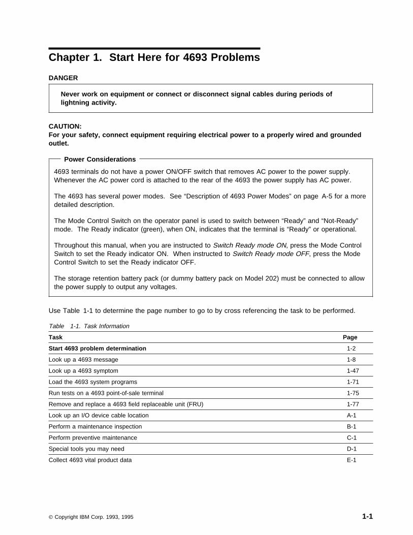
Use Table 1-1 to determine the page number to go to by cross referencing the task to be performed.
Table 1-1. Task Information
Task Page
Start 4693 problem determination 1-2
Look up a 4693 message 1-8
Look up a 4693 symptom 1-47
Load the 4693 system programs 1-71
Run tests on a 4693 point-of-sale terminal 1-75
Remove and replace a 4693 field replaceable unit (FRU) 1-77
Look up an I/O device cable location A-1
Perform a maintenance inspection B-1
Perform preventive maintenance C-1
Special tools you may need D-1
Collect 4693 vital product data E-1
Copyright IBM Corp. 1993, 1995 1-1

4693 Problem Determination
Table 1-2. Start 4693 Problem Determination
Condition Action
You have one of these messages in the storecontroller system log or displayed at a store controller.
� Application program status xxx*� Annn through Snnn
� Wnnn � Xnnn � Ynnn � Znnn
Follow the User Response for the message in “4693Messages” or the IBM 4690 Store System: MessagesGuide or the documentation for the application program.
Note: In the xxx* (application program status) message, the xxx can be any characters. The asterisk (*) appears atthe end of all these messages.
You have a Mnnnn message displayed. Follow the User Response for the message at “MnnnnMessages” on page 1-35.
You have a power-on self-test (POST) messagedisplayed.
Follow the User Response for the message at “4693Power-On Self-Test Messages” on page 1-11.
You have an Ethernet network message displayed. Follow the User Response for the message at “EthernetMessages” on page 1-25.
You have a PC network message displayed. Follow the User Response for the message at “PCNetwork Messages” on page 1-26.
You have a token-ring network message displayed. Follow the User Response for the message at “Token-RingMessages” on page 1-28.
You have a 63nn message displayed when loadingsystem programs.
Follow the User Response for the message at “63nnMessages” on page 1-31.
You have a Tnnnn message displayed. Follow the User Response for the message at “TnnnnMessages” on page 1-39.
You have a problem symptom at a 4693 terminal. Follow the Action for the symptom at “4693 Symptoms” onpage 1-47.
You have a Unnn message (U001 through U009)displayed at a 4693 terminal.
Follow the User Response for the message at “UnnnMessages” on page 1-45.
You have a blank display at a 4693 terminal. Go to “Input/Output Device Symptoms” on page 1-50.
You have multiple problem symptoms at a 4693terminal or more than one point-of-sale device appearsto be failing.
Go to “MAP 0100: General Checkout” on page 1-3.
You have a 4693 terminal in an unknown state or hangcondition and you do not know where to begin problemdetermination.
Go to “MAP 0100: General Checkout” on page 1-3.
1-2 4693, 4694, and 4695 Hardware Service Manual
MAP 0100: General Checkout
Symptom Explanation Conditions That Could Cause This Symptom
This MAP serves as a generalcheckout procedure to use whenyou do not know where to beginproblem determination.
Use the error codes displayed todiagnose failures when possible. Ifmore than one error code isdisplayed, begin the diagnosis withthe first error code. The cause ofthe first error code can result infalse errors being displayed. If noerror code is displayed, see “4693Symptoms” on page 1-47 and lookfor a symptom that matches thefailure you are experiencing.
� This MAP is a general checkout for any 4693 terminal.Any of the field replaceable units (FRUs) may be the causeof your failure.
Notes:
1. The storage retention battery pack (or dummy battery pack on Model xx2) must be connected to allowthe power supply to output any voltages.
2. The diagnostic tests are intended to test only IBM devices. Non-IBM devices, prototype adapters, ormodified options can give false errors and system responses that are not valid.
3. The terminal system board may have several FRUs attached. An error code or symptom may becaused by any of the FRUs. Before exchanging the terminal system board, remove the attachedFRUs, one at a time, to see if the symptoms change. When a terminal system board is exchangedand the error code or symptom remains the same, remove the new system board and install theoriginal back into the terminal.
4. To disable the power-on password , move the password jumper to the unused position. See 1-91 forjumper location.
5. Model Numbers - When this MAP discusses terminal models, xx can be any number or letter.
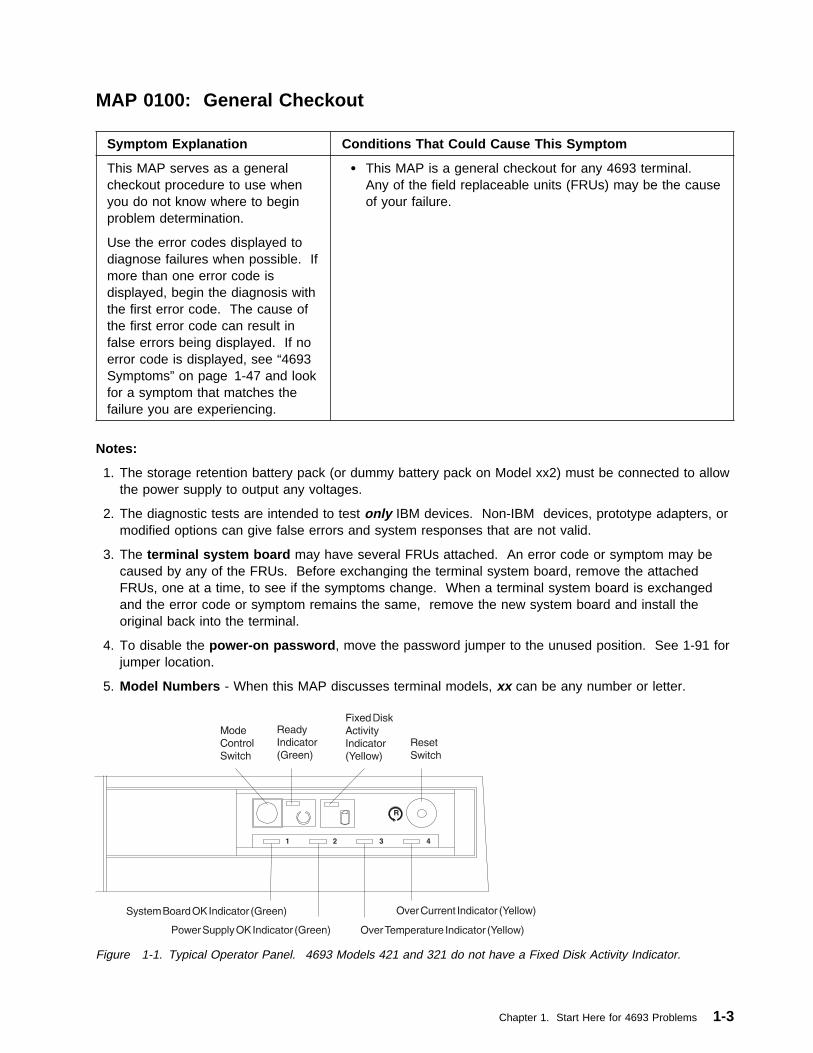
Figure 1-1. Typical Operator Panel. 4693 Models 421 and 321 do not have a Fixed Disk Activity Indicator.
Chapter 1. Start Here for 4693 Problems 1-3

MAP 0100 (continued)
001
– Switch Ready mode OFF at the 4693.– Switch POWER OFF at all external devices.– Make sure all cables and the AC power cord
are connected properly and are not damaged.– Make sure there is no diskette in the diskette
drive (if terminal has a drive).– Make sure the video display, if present, has its
brightness control set approximately in themiddle position.
– Press the Reset button on the operator panel.When Reset is pressed, storage retention isdisabled.– Switch power ON at all external devices.– Switch Ready mode ON at the terminal and wait
10 seconds.– Observe the indicator lights on the operator
panel. See Figure 1-1 on page 1-3. Thenormal condition of the lights are:
Are the indicator lights normal?Yes No
002
Go to “4693 Operator Panel Indicators andSwitches” on page 1-51.
003
– Switch Ready mode OFF.– Switch Ready mode ON and observe the
display for a power-on self-test (POST) errorcode. Write down any error codes that aredisplayed.
Note: You will hear 2 or more beeps if aPOST error is detected and 1 beep if no errorsare detected.
If the test stops and you cannot continue, see“4693 Messages” on page 1-8 or “4693Symptoms” on page 1-47.
(Step 003 continues)
003 (continued)Did you hear just one beep at the end ofPOST?Yes No
004
Go to “4693 Messages” on page 1-8.– or –Go to “4693 Symptoms” on page 1-47.
005
.– Switch Ready Mode OFF.– Load the system programs. See “Loading the
System Programs” on page 1-71.For a 4693 Model 541 with a fixed disk, thesystem programs are loaded from the fixed disksystem partition. If this is a medialess terminal(no fixed disk) the system programs image aredownloaded from the store controller/server overthe store loop or network.
Note: You may be asked to press the 1 key onthe numeric keypad before the MAIN MENUappears.Did the MAIN MENU appear?Yes No
006
Go to Step 012 on page 1-5.
007
– See “Flow of 4693 System Programs Menus” onpage 1-73.
– Select START TESTS from the MAIN MENU.– Select RUN SYSTEM UNIT TESTS.– Select TEST SYSTEM UNIT.– Select RUN TESTS ONE TIME.– Select TEST ALL DEVICES.Did the system unit tests run error free?Yes No
008
Follow the displayed instructions orexchange the device associated with theerror code.
009
– Select START TESTS from the MAIN MENU.(Step 009 continues)
Ready Indicator (green) ONIndicator 1 (system board OK) ONIndicator 2 (power supply OK) ONIndicator 3 (overtemperature) OFFIndicator 4 (overcurrent) OFF
1-4 4693, 4694, and 4695 Hardware Service Manual

009 (continued)– Select RUN POS DEVICE TESTS.– Select the terminal to be tested.– Test all the POS devices listed in the test menu.Did the POS device tests run error free?Yes No
010
Go to “MAP 0110: Input/Output (I/O)Device Isolation” on page 1-6.
011
You may have an intermittent problem.
� Check for damaged cables or connectors.� Reseat all adapters, drives, and pluggable
modules.� Start an error log and run system unit tests
multiple times.� Reset the configuration and the terminal load.
See page 1-76.Attention Resetting configuration destroys theconfiguration record currently stored in NVRAM.Use it only when it seems necessary due to hangconditions, undetermined problems, or aninoperative system.� Contact your support organization.
012
(From step 006) .Did any error messages display?Yes No
013
If your display is blank (dark):
� Make sure the display is properlyconnected to the rear connector panel.
� For a video display:– Make sure that it is connected to a
known good AC power source andthat its power is switched ON.
– Check the fuse for the video ACpower outlet on the rear panel.
– Set the brightness controlapproximately to its middle position.
� Exchange the display and cable with aknown good display or, if none isavailable, exchange the display or seethe maintenance documentation for yourdisplay.
– or –Go to “4693 Symptoms” on page 1-47 or“4693 Messages” on page 1-8.
014
Go to “4693 Messages” on page 1-8.
Chapter 1. Start Here for 4693 Problems 1-5

MAP 0110: Input/Output (I/O) Device Isolation
Symptom Explanation Conditions That Could Cause This Symptom
You have an error message or avisible or audible symptomindicating that an I/O device isfailing.
� I/O device� I/O device cable� Rear connector panel
� System board
Notes:
1. See the Store Systems: Hardware Service Manual for Point-of-Sale Input/Output Devices for adescription of cash drawer, keyboard, MSR, and printer Tnnnn messages that display while runningPOS device tests.
2. Some of the POS I/O devices can be repaired while others are simply exchanged when they fail. Seethe Store Systems: Hardware Service Manual for Point-of-Sale Input/Output Devices to determine if arepair procedure exists for an I/O device.
3. The diagnostic tests are intended to test only IBM devices. Non-IBM devices, prototype adapters, ormodified options can give false errors and system responses that are not valid.
001
– Switch Ready mode OFF at the 4693.– Press the Reset switch on the operator panel.When Reset is pressed, storage retention isdisabled.– Switch power ON at all external devices.– Switch Ready mode ON at the terminal and wait
10 seconds.– Observe the indicator lights on the operator
panel. The normal condition of the lights are:
Are the indicator lights normal?Yes No
002
Go to “4693 Operator Panel Indicators andSwitches” on page 1-51.
003
Is more than one I/O device failing?Yes No
004
(Step 004 continues)
004 (continued)Go to Step 006.
005
It is possible that one failing device can causeothers to fail also.– Switch Ready mode OFF.– Disconnect each of the I/O devices, one at a
time, to help determine which one is causingthe failure. Retest for the failure after eachdevice is disconnected.
Attention Switch Ready mode OFF whenever youare disconnecting or connecting devices.Exchange or repair the failing I/O device andcable. See the Store Systems: Hardware ServiceManual for Point-of-Sale Input/Output Devices forrepairable devices.
006
(From step 004)– Switch Ready mode OFF.– Make sure the cable for the failing device is
properly connected both to the device and tothe rear connector panel of the 4693.
Are the connections OK?Yes No
007
– Correct the connection problem and testto make sure the failure no longer occurs.
Ready Indicator (green) ONIndicator 1 (system board OK) ONIndicator 2 (power supply OK) ONIndicator 3 (overtemperature) OFFIndicator 4 (overcurrent) OFF
1-6 4693, 4694, and 4695 Hardware Service Manual

008
Is the failing device a printer?Yes No
009
Go to Step 011.
010
Printers have standalone self-tests that are helpfulin isolating problems between the printer and theterminal.For POS printers see the Store Systems:Hardware Service Manual for Point-of-SaleInput/Output Devices to run standalone self-tests.For parallel printers such as an IBM Proprinter*,see the printer maintenance information forself-test instructions.Continue at Step 016 if necessary.
011
(From step 009)Is the failing device a video display?Yes No
012
Go to Step 016.
013
– Make sure the video display is connected to aknown good AC power source and that itspower switch is switched ON.
– If the video display is plugged into the video ACpower outlet at the rear of the 4693, make surethe fuse is not blown.
– Make sure the video display brightness controlis set approximately in the middle position.
Did you discover a problem with the videodisplay connections or power?Yes No
014
If this is a monochrome video display,exchange the display.– or –If this is a color video display, see themaintenance documentation for yourdisplay.(Step 014 continues)
014 (continued)– or –Exchange the video display cable.
015
Correct the problem that was found and test tomake sure the failure no longer occurs.
016
(From steps 010 and 012)Is another working I/O device, like the failingone, available to attach to this 4693?Yes No
017
Go to Step 020.
018
– Switch Ready mode OFF.– Connect the working I/O device to this 4693.– Switch Ready mode ON and determine if the
failure still occurs.Does the same failure still occur?Yes No
019
The original I/O device or its cable is failing.Exchange or repair the device and cable.See the Store Systems: Hardware ServiceManual for Point-of-Sale Input/OutputDevices for repairable devices.
020
(From step 017)Exchange or repair the device and its cable. Seethe Store Systems: Hardware Service Manual forPoint-of-Sale Input/Output Devices for repairabledevices.– or –Exchange the rear connector panel. See“Removing and Replacing the Rear ConnectorPanel” on page 1-87.– or –Exchange the system board. See “Removing andReplacing the Terminal System Board” onpage 1-86.
Chapter 1. Start Here for 4693 Problems 1-7

4693 Messages
How To Read 4693 Power-On Self-Test (POST) Messages . . . . . . . . . . . . . . . . . . . . . . 1-9How To Retrieve Network Remote Program Load (RPL) Messages . . . . . . . . . . . . . . . . . . 1-9Power-On Self-Test Message Index . . . . . . . . . . . . . . . . . . . . . . . . . . . . . . . . . . . 1-104693 Power-On Self-Test Messages . . . . . . . . . . . . . . . . . . . . . . . . . . . . . . . . . . . 1-11Ethernet Messages . . . . . . . . . . . . . . . . . . . . . . . . . . . . . . . . . . . . . . . . . . . . . 1-25PC Network Messages . . . . . . . . . . . . . . . . . . . . . . . . . . . . . . . . . . . . . . . . . . . 1-26Token-Ring Messages . . . . . . . . . . . . . . . . . . . . . . . . . . . . . . . . . . . . . . . . . . . 1-2863nn Messages . . . . . . . . . . . . . . . . . . . . . . . . . . . . . . . . . . . . . . . . . . . . . . . 1-31Application Program Status xxx* . . . . . . . . . . . . . . . . . . . . . . . . . . . . . . . . . . . . . 1-34Annn through Lnnn and Nnnn through Snnn Messages . . . . . . . . . . . . . . . . . . . . . . . . 1-34Mnnnn Messages . . . . . . . . . . . . . . . . . . . . . . . . . . . . . . . . . . . . . . . . . . . . . . 1-35Tnnnn Messages . . . . . . . . . . . . . . . . . . . . . . . . . . . . . . . . . . . . . . . . . . . . . . 1-39Unnn Messages . . . . . . . . . . . . . . . . . . . . . . . . . . . . . . . . . . . . . . . . . . . . . . . 1-45Wnnn Messages . . . . . . . . . . . . . . . . . . . . . . . . . . . . . . . . . . . . . . . . . . . . . . . 1-46Xnnn Messages . . . . . . . . . . . . . . . . . . . . . . . . . . . . . . . . . . . . . . . . . . . . . . . 1-46Ynnn Messages . . . . . . . . . . . . . . . . . . . . . . . . . . . . . . . . . . . . . . . . . . . . . . . 1-46Znnn Messages . . . . . . . . . . . . . . . . . . . . . . . . . . . . . . . . . . . . . . . . . . . . . . . 1-46
DANGER
Never work on equipment or connect or disconnect signal cables during periods oflightning activity.
CAUTION:For your safety, connect equipment requiring electrical power to a properly wired and groundedoutlet.
Operating System or Application Messages
The operating system or an application may display messages that do not appear in this manual. Seethe documentation for the appropriate operating system or application program.
Note: On keyboards that have a Ctrl key, the S1 and S2 functions require a combination of two keys.First press and hold the Ctrl key then press the S1 or S2 key .
1-8 4693, 4694, and 4695 Hardware Service Manual

How To Read 4693 Power-On Self-Test (POST) Messages
Most POST error messages are displayed as an eight character message. Occasionally one may displaythat has less than eight characters. When this occurs, you can ignore the leading and trailing zeros of themessages in this list.
Note: n = any hexadecimal character (0-9 and A-F).
An example of one of these messages is:
00110100 (eight character) 1101 (four character)
The breakdown of an eight digit message is as follows:
0 = First digit011 = Device number01 = Error number0 = Slot number0 = Modifier
How To Retrieve Network Remote Program Load (RPL) Messages
When a medialess terminal is performing a remote program load from a network server, several importantmessages are displayed. If a video display is present, these messages are displayed using the full screenand are easily available. However, when a 40-character display is being used, the messages appear toofast to be read. Use the following procedure to retrieve Ethernet and token-ring network RPL messages.
1 Make a note of the position of the manager’s keylock position. While the ET–nn:nn:nn is displayed,switch the manager keylock on the keyboard to a different position. This change is sensed by theprogram and enables the S2 and S1 keys to be used for message retrieval.
Note: For enhanced alphanumeric keyboards (PS/2* type), there is no manager keylock. PressCtrl + Alt + Home . Then use the up and down cursor keys to retrieve the messages.
2 Press the S2 key to display the previous message. Pressing the S2 key several times may berequired to retrieve all the messages.
Note: Keyboards with a Ctrl key require Ctrl + S2 or Ctrl + S1.
3 After retrieving the messages, you can press the S1 key to move back to the ET– nn:nn:nnmessage. Switching the manager keylock to its original position also displays the ET messageagain.
4 When finished retrieving RPL messages, be sure to switch the manager keylock to its originalposition.
Chapter 1. Start Here for 4693 Problems 1-9
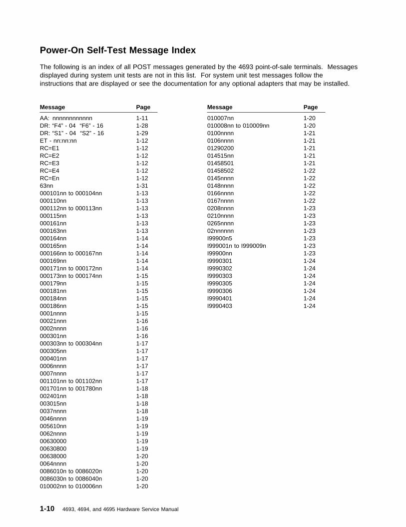
Power-On Self-Test Message Index
The following is an index of all POST messages generated by the 4693 point-of-sale terminals. Messagesdisplayed during system unit tests are not in this list. For system unit test messages follow theinstructions that are displayed or see the documentation for any optional adapters that may be installed.
Message Page Message Page
AA: nnnnnnnnnnnn 1-11 010007nn 1-20DR: “F4” - 04 “F6” - 16 1-28 010008nn to 010009nn 1-20DR: “S1” - 04 “S2” - 16 1-29 0100nnnn 1-21ET - nn:nn:nn 1-12 0106nnnn 1-21RC=E1 1-12 01290200 1-21RC=E2 1-12 014515nn 1-21RC=E3 1-12 01458501 1-21RC=E4 1-12 01458502 1-22RC=En 1-12 0145nnnn 1-2263nn 1-31 0148nnnn 1-22000101nn to 000104nn 1-13 0166nnnn 1-22000110nn 1-13 0167nnnn 1-22000112nn to 000113nn 1-13 0208nnnn 1-23000115nn 1-13 0210nnnn 1-23000161nn 1-13 0265nnnn 1-23000163nn 1-13 02nnnnnn 1-23000164nn 1-14 I99900n5 1-23000165nn 1-14 I999001n to I999009n 1-23000166nn to 000167nn 1-14 I99900nn 1-23000169nn 1-14 I9990301 1-24000171nn to 000172nn 1-14 I9990302 1-24000173nn to 000174nn 1-15 I9990303 1-24000179nn 1-15 I9990305 1-24000181nn 1-15 I9990306 1-24000184nn 1-15 I9990401 1-24000186nn 1-15 I9990403 1-240001nnnn 1-1500021nnn 1-160002nnnn 1-16000301nn 1-16000303nn to 000304nn 1-17000305nn 1-17000401nn 1-170006nnnn 1-170007nnnn 1-17001101nn to 001102nn 1-17001701nn to 001780nn 1-18002401nn 1-18003015nn 1-180037nnnn 1-180046nnnn 1-19005610nn 1-190062nnnn 1-1900630000 1-1900630800 1-1900638000 1-200064nnnn 1-200086010n to 0086020n 1-200086030n to 0086040n 1-20010002nn to 010006nn 1-20
1-10 4693, 4694, and 4695 Hardware Service Manual

Power-On Self-Test Messages � DR: “S1” - 04 “S2” - 16
4693 Power-On Self-Test Messages
When the Mode Control Switch is pressed to switch Ready mode ON and storage retention is disabled,POST is automatically performed on the system unit and some adapters. These tests provide messagesthat indicate errors or status detected by the POST.
If you have an error code that is not in this list, check “How To Read 4693 Power-On Self-Test (POST)Messages” on page 1-9 to see if your error code can be translated to an error code that is in this list. Ifyour error code does not translate into a listed error code, it may be for an optional adapter that was notrecognized at the time this document was printed. Contact the store programmer for more information orsee the documentation that came with the adapter.
Attention Switching Ready mode OFF at a store controller or network server affects operations at allpoint-of-sale terminals attached to it.
AA: nnnnnnnnnnnnnnnnnnnnnnnn = network adapter address (12 hexadecimal characters)
Explanation: This message is displayed to help the user when starting up a network or when networkproblems occur.
User Response: Contact the network administrator to define this adapter address to the networkserver software. When the adapter address has been defined, press any key to continue.
DR: “F4” - 04 “F6” - 16
Explanation: This message appears when a 16/4 Token-Ring Adapter/A is installed and has not beenconfigured to select the data rate.
User Response: You must determine the correct data rate for your token-ring network. Contact thestore programmer, help desk, installation planner, or store support personnel for this information.
On the PC keyboard:
Press the F4 key if the data rate is 4 Mbyte/sec.
Press the F6 key if the data rate is 16 Mbyte/sec.
Note: If a similar message appears again, make sure that the correct data rate was chosen and selectthe correct data rate again. If this message continues to appear, contact the network administrator.
DR: “S1” - 04 “S2” - 16
Explanation: This message appears when a 16/4 Token-Ring Adapter/A is installed and has not beenconfigured to select the data rate.
User Response: You must determine the correct data rate for your token-ring network. Contact thestore programmer, help desk, installation planner, or store support personnel for this information.
On the POS keyboard:
Press the S1 key if the data rate is 4 Mbyte/sec.
Press the S2 key if the data rate is 16 Mbyte/sec.
Note: If a similar message appears again, make sure that the correct data rate was chosen and selectthe correct data rate again. If this message continues to appear, contact the network administrator.
Chapter 1. Start Here for 4693 Problems 1-11

ET - nn:nn:nn or nn:nn:nn � RC=En
ET - nn:nn:nn or nn:nn:nn
Explanation: This message indicates the elapsed time of a network load. Normally it increments untilthe load is complete.
User Response: If the elapsed time stops incrementing or increments for an unreasonable length oftime, see “4693 Messages” on page 1-8 and go to the messages for your type of network.
RC=E1
Explanation: Base driver functions not available. A 0145nnnn message was probably displayed priorto this message.
User Response:
� If 0145nnnn was displayed, follow the User Response for 0145nnn to correct this problem.� If 0145nnnn was not displayed, see “Utilities Procedure Using System Programs” on page 1-75 to
create a new backup reference diskette.
RC=E2
Explanation: A device driver is already installed for this device.
User Response: Load the system programs and run CHANGE CONFIGURATION to configure theterminal. See “Utilities Procedure Using System Programs” on page 1-75.
Note: If this occurs using the application diskette, contact the store programmer.
RC=E3 nnnnnnnn RC=E3nnnnnnnn = 8 character device driver handle
Explanation: A device identified by the driver handle that precedes the RC=E3 is configured but notattached or is failing.
User Response:
1 Ensure that all devices are properly attached to the terminal.
2 If a model xx2 terminal is present, ensure that its Ready indicator is ON and it is connected to the4693 master terminal with cable 11.
3 There is often a 63nn message that displays before or after the RC=E3 message. Continueproblem determination using the User Response for the 63nn message.
RC=E4
Explanation: The DSP480 or AKY-BIOS.SYS device driver is required but has not been installed.
User Response:
� If you are using the backup reference diskette and the problem persists, see “Utilities ProcedureUsing System Programs” on page 1-75 to create a new backup reference diskette.
� If you are not using the reference diskette and the problem persists, ensure that the DSP480 andAKY-BIOS.SYS device drivers are available. Also ensure that the DSP480 entry in theCONFIG.SYS file is correct.
RC=En
Explanation: The base driver has detected an error. A 0145nnnn message was probably displayedprior to this message.
Note: In this message, n = any letter from a to u.
User Response:
� If 0145nnnn see 0145nnnn message in this list.� If 0145nnnn was not displayed, create a new backup reference diskette and update the system
1-12 4693, 4694, and 4695 Hardware Service Manual

000101nn to 000104nn � 000163nn
programs with the new backup reference diskette. See “Utilities Procedure Using SystemPrograms” on page 1-75.
000101nn to 000104nn
Explanation: A terminal system board error occurred.
User Response:
Exchange the terminal system board. See page 1-86.
000110nn
Explanation: A system board parity check error occurred.
User Response: Load the system programs and run system unit tests to test the memory. See “TestProcedure Using System Programs” on page 1-75.
� If the tests do not indicate which memory module failed, exchange the modules one at a time until
you determine the one that failed. See page 1-85.� If the problem persists after exchanging the modules, exchange the terminal system board. See
page 1-86.
Note: Tests may deallocate defective memory. After you exchange memory always run the teststo recognize the new memory module.
000112nn and 000114nn
Explanation: A terminal system board error occurred.
User Response:
Note: Any adapter can cause these errors to occur.
1 Switch Ready mode OFF and remove all optional adapters from the terminal. See page 1-85.
2 Switch Ready mode ON and see if the same error occurs.� If the same error no longer occurs, one of the adapters that was removed is failing.
Exchange them one at a time to determine the failing adapter.
Note: 4693 Models 321 and 421 can have only one loop or network adapter present.� If the problem persists, exchange the terminal system board. See page 1-86.
000115nn (4693-541, (Fixed Disk))
Explanation: The IML image has an error, or ROM has failed.
User Response:
1 Update the system partition using the reference diskette.
2 If the error still exists, exchange the system board.
000161nn
Explanation: A nonvolatile storage error occurred.
User Response: Exchange the terminal system board. See page 1-86.
000163nn
Explanation: A date and time error occurred.
User Response: Run the SET DATE AND TIME utility if it has not been run.
If the problem persists, switch Ready mode OFF and exchange the terminal system board. See page1-86.
Chapter 1. Start Here for 4693 Problems 1-13

000164nn � 000171nn and 000172nn
000164nn
Explanation: A nonvolatile storage error occurred.
User Response:
1 Load the system programs. See page 1-71.
2 Select START CONFIGURATION from the MAIN MENU.
3 Select AUTO CONFIGURATION from the CONFIGURATION MENU and follow the instructions onthe display.
4 If the problem persists, exchange the terminal system board. See page 1-86.
000165nn
Explanation: A configuration error was detected during POST. If an option adapter has been recentlyadded, the configuration program should be run to update the configuration record in NVRAM.
User Response:
1 The system programs load automatically.
2 When message M0101 is displayed, answer YES.
3 If any error messages are displayed, find the message in this list and follow the User Response.
4 Follow the instructions on the display.
5 If the problem persists, exchange the terminal system board. See page 1-86.
000166nn and 000167nn
Explanation: A terminal system board error was detected.
Note: Any adapter can cause these errors to occur.
User Response:
1 Switch Ready mode OFF and remove all optional adapters from the terminal. See page 1-85.
2 Switch Ready mode ON and see if the same error occurs.� If the same error no longer occurs, one of the adapters that was removed is failing.
Exchange them one at a time to determine the failing adapter.� If the problem persists, exchange the terminal system board. See page 1-86.
000169nn
Explanation: A terminal configuration or system board error was detected.
User Response:
1 The system programs load automatically.
2 When message M0101 is displayed, answer YES.
3 If any error messages are displayed, find the message in this list and follow the User Response.
4 Follow the instructions on the display.
5 If the problem persists, exchange the terminal system board. See page 1-86.
000171nn and 000172nn
Explanation: A terminal system board error occurred.
User Response: Exchange the terminal system board. See page 1-86.
1-14 4693, 4694, and 4695 Hardware Service Manual

000173nn to 000174nn � 0001nnnn (not listed above)
000173nn to 000174nn
Explanation: A configuration or hardware error occurred. Any one of the option adapters in theterminal can cause this problem.
User Response:
1 The system programs load automatically.
2 When message M0101 is displayed, answer YES if an option adapter has been added orremoved recently.
3 If any error messages are displayed, find the message in this list and follow the User Response.
4 Follow the instructions on the display.
5 If the problem persists, exchange the terminal system board. See page 1-86.
If an option adapter has not been added or removed recently, run system unit tests to help isolate thefailing device. See “Test Procedure Using System Programs” on page 1-75.
000179nn
Explanation: The NVRAM error log is full.
User Response:
1 Load the system programs and select START UTILITIES. See “Utilities Procedure Using SystemPrograms” on page 1-75.
2 Select DISPLAY NVRAM ERROR LOG.
3 Reset the log after displaying the errors.
000181nn
Explanation: The configuration is not valid. No boot device was found.
User Response: Ensure that a network adapter is installed in the terminal.
If no network adapter is installed, you must install one to prevent this error from reoccurring.
If a network adapter is installed, exchange it. See page 1-85.
000184nn
Explanation: The power-on password is corrupted.
User Response: Load the system programs and enter a new password. See “Utilities ProcedureUsing System Programs” on page 1-75.
000186nn
Explanation: A security error was detected during POST.
User Response: Exchange the terminal system board. See page 1-85.
0001nnnn (not listed above)
Explanation: Any other 0001nnnn messages not listed above.
User Response: Exchange the terminal system board. See page 1-86.
Chapter 1. Start Here for 4693 Problems 1-15
00020nnn � 000301nn and 000302nn
00020nnn
Explanation: A terminal system board memory error occurred.
User Response: Load the system programs and run system unit tests to test the memory. See “TestProcedure Using System Programs” on page 1-75.
� If the tests do not indicate which memory module failed, exchange the modules one at a time untilyou determine the one that failed. See page 1-85.
� If the problem persists after exchanging the modules, exchange the terminal system board. Seepage 1-86.
Notes:
1. Always switch Ready mode OFF when exchanging memory modules.2. Tests may deallocate defective memory. After you exchange memory always run the tests to
recognize the new memory module.
00021nnn
Explanation: An unrecoverable memory error occurred in the first megabyte of memory.
User Response: Make sure that the memory module is installed properly. See Figure 1-11 onpage 1-85 for location of memory modules.
If the module is installed correctly, exchange the memory module. See page 1-85.
000225nn
Explanation: A memory module of the wrong type was detected.
User Response:
1 Make sure that the memory modules installed are of the correct type for this terminal. See theStore Systems: Parts Catalog.
2 Remove the memory modules, one at a time, until the problem goes away. See page 1-85.When this happens, either the last memory module removed or the terminal system board isfailing. Install a known good memory module of the correct type into the same connector. If theproblem persists, exchange the terminal system board. See page 1-86.
000301nn and 000302nn
Explanation: A system unit keyboard error occurred.
User Response: Switch Ready mode OFF and follow this list to isolate and correct the cause of theproblem.
1 Ensure the keyboard is attached to the Kybd socket on the rear connector panel. SeeFigure A-3 on page A-4.
2 Ensure that no keys are pressed during the initial program load (IPL).
3 Exchange or service the system unit keyboard. Go to the Store Systems: Hardware ServiceManual for Point-of-Sale Input/Output Devices.
4 Exchange the system unit keyboard cable.
5 Exchange the terminal system board. See page 1-86.
1-16 4693, 4694, and 4695 Hardware Service Manual

000303nn and 000304nn � 001101nn to 001102nn
000303nn and 000304nn
Explanation: A terminal system unit keyboard error occurred. This message can only be caused bythe keyboard attached to the Kybd socket on the rear connector panel.
User Response:
1 Ensure the keyboard is correctly attached to the Kybd socket on the rear connector panel.See Figure A-3 on page A-4.
2 Exchange or service the system unit keyboard and cable. Go to the Store Systems: HardwareService Manual for Point-of-Sale Input/Output Devices.
000305nn
Explanation: An error occurred on the terminal system unit keyboard.
User Response:
1 Exchange the system unit keyboard cable.
2 Exchange the terminal system board. See page 1-86.
000401nn to 000501nn
Explanation: A terminal system board error occurred.
User Response: If the problem persists, exchange the terminal system board. See page 1-86.
000602nn
Explanation: The diskette IPL boot record is not valid.
User Response: Try another diskette. If failure continues, see the User Response for 0006nnnn.
0006nnnn
Explanation: A 4693 diskette drive error occurred while trying to load programs from the diskette.
User Response:
1 Load the system programs from the fixed disk. See “Loading the System Programs” onpage 1-71 and “Test Procedure Using System Programs” on page 1-75.
2 Run system unit tests to test the diskette drive.� If an error is detected, follow the displayed instructions.� If no error is detected, try using a different diskette to load programs.� If the problem persists, exchange the diskette drive. See page 1-82.
0007nnnn
Explanation: A math coprocessor or system board error occurred.
User Response:
1 Exchange the math coprocessor module on the terminal system board.
2 Exchange the terminal system board. See page 1-86.
001101nn to 001102nn
Explanation: A terminal system board asynchronous port error occurred.
User Response:
1 Switch Ready mode OFF.
2 Disconnect the cables attached to the SERIAL A and SERIAL B socket.
3 Switch Ready mode ON.
Chapter 1. Start Here for 4693 Problems 1-17
001701nn through 001718nn � 0037nnnn
� If the problem is corrected by disconnecting the cables, switch Ready mode OFF and reconnect thedevices that were attached to SERIAL A and SERIAL B one at a time until the failing device isdetermined.
� If the problem is not corrected by disconnecting the cables, exchange the terminal system board.See page 1-86.
001701nn through 001718nn
Explanation: A fixed disk test error occurred.
User Response:
Note: Message 1713 is a status message only, no action is required.
1 Exchange the fixed disk cable.
2 Exchange the fixed disk.
Note: The user may want to try to backup the fixed disk before exchanging. Otherwise, userdata may be lost.
001780nn
Explanation: A fixed disk configuration error or fixed disk failure occurred.
User Response: Run Setup.
If running Setup does not correct the problem:
1 Exchange the fixed disk cable.
2 Exchange the fixed disk.
0024nnnn
Explanation: A system board video error occurred.
User Response:
1 If possible, load the system programs and run system unit tests to test the video adapter. See“Test Procedure Using System Programs” on page 1-75.
2 If the problem persists, exchange the terminal system board. See page 1-86.
003015nn
Explanation: A PC Network Baseband Adapter error occurred.
User Response:
1 Check for a missing wrap or terminator plug on the adapter.
2 Exchange the PC Network Baseband adapter. See page 1-85.
0037nnnn
Explanation: A SCSI adapter error occurred.
User Response:
1 Exchange the terminal system board. See page 1-86.
2 Exchange the fixed disk. See page 1-84.
3 Exchange the fixed disk cable. See page 1-84.
1-18 4693, 4694, and 4695 Hardware Service Manual

0046nnnn � 00630800
0046nnnn
Explanation: A Real-time Interface Coprocessor Multiport/2 (ARTICm/2) or X.25/2 (ARTICx/2) adaptererror occurred.
User Response: Load the system programs and run system unit tests to test the real-time interfacecoprocessor. See “Test Procedure Using System Programs” on page 1-75.
005610nn
Explanation: The DSP480 device driver related font file has not been installed. by this Explanationand User Response.
User Response:
1 Ensure that the related font file names in the DSP480 entry of the CONFIG.SYS file are correct.
2 Ensure that the related font files referenced in the DSP480 entry of the CONFIG.SYS file areavailable.
0062nnnn
Explanation: A store loop adapter error occurred.
User Response: Load the system programs and run system unit tests to test the store loop adapter.See “Test Procedure Using System Programs” on page 1-75.
00630000
Explanation: The 4693-xx1 I/O configuration record is corrupted. This message can be caused bysystem software or by a failing terminal system board. POST attempts to correct this conditionautomatically.
User Response:
1 Load the system programs. See “Loading the System Programs” on page 1-71 and “UtilitiesProcedure Using System Programs” on page 1-75.
2 Select START CONFIGURATION from the MAIN MENU.
3 Select AUTO CONFIGURATION from the CONFIGURATION MENU.
4 Follow the instructions on the display.
� If the problem persists, exchange the 4693-xx1 terminal system board. See page 1-86.
00630800
Explanation: The 4693-xx2 I/O configuration record, stored in the 4693-xx1 NVRAM, is corrupted.This message can be caused by system software or by a failing terminal system board. Power-OnSelf-Test (POST) attempts to correct this condition automatically.
User Response:
1 Load the system programs. See “Loading the System Programs” on page 1-71 and “UtilitiesProcedure Using System Programs” on page 1-75.
2 Select START CONFIGURATION from the MAIN MENU.
3 Select AUTO CONFIGURATION from the CONFIGURATION MENU.
4 Follow the instructions on the display.
� If the problem persists, exchange the 4693-xx1 terminal system board. See page 1-86.
Chapter 1. Start Here for 4693 Problems 1-19

00638000 � 010008nn and 010009nn
00638000
Explanation: The 4693-xx2 terminal NVRAM data is corrupted. POST attempts to correct thiscondition automatically.
User Response: If the problem persists, exchange the 4693-xx2 terminal system board. See page1-86.
0064nnnn
Explanation: An Ethernet adapter error occurred.
Note: Error codes 006418nn through 006424nn can be caused by a loose or improper LAN cableconnection or by activity on a live network.
User Response: Verify the LAN cable connection or termination and retry the test. If the errorcontinues, see “Ethernet Messages” on page 1-25 or exchange the Ethernet adapter. See page 1-85.
0086010n to 0086020n
Explanation: A pointing device (mouse) error occurred.
User Response: Exchange the pointing device (mouse).
008603nn and 008604nn
Explanation: A pointing device (mouse) error occurred.
User Response:
1 Exchange the pointing device.
2 If the problem persists, exchange the terminal system board. See page 1-86.
010002nn through 010006nn
Explanation: A multiprotocol adapter error occurred.
User Response:
1 Load the system programs and run system unit tests to test the MPA. See “Test Procedure UsingSystem Programs” on page 1-75.
2 If the problem persists, exchange the Multiprotocol Adapter/A.
010007nn
Explanation: A multiprotocol adapter communications error occurred.
User Response:
1 Exchange the communications cable attached to the Multiprotocol Adapter/A.
2 Switch Ready mode ON and see if the error still occurs.
3 If the problem persists, exchange the Multiprotocol Adapter/A. See page 1-85.
010008nn and 010009nn
Explanation: A multiprotocol adapter communications error occurred.
User Response:
1 Exchange the Multiprotocol Adapter/A. See page 1-85.
2 If exchanging the multiprotocol adapter fails to correct the problem, any external serial device cancause this error. Disconnect the serial devices one at a time to help isolate the failing device.
1-20 4693, 4694, and 4695 Hardware Service Manual

0100nnnn � 01458501
0100nnnn
Explanation: A multiprotocol adapter communications error occurred.
User Response:
1 Exchange the Multiprotocol Adapter/A. See page 1-85.
2 Exchange the terminal system board. See page 1-86.
0106nnnn
Explanation: An Ethernet adapter error occurred.
User Response:
1 Exchange the Ethernet adapter. See page 1-85.
2 Exchange the terminal system board. See page 1-86.
0129nnnn
Explanation: A system board error occurred.
User Response: Exchange the terminal system board. See page 1-85.
0133nnnn
Explanation: An IBM Wireless LAN adapter error occurred.
User Response:
1 Run the IBM Wireless LAN tests.
2 Continue problem determination using the maintenance documentation provided with the IBMWireless LAN. See the “Troubleshooting Wireless Network Problems” appendix in the IBMWireless LAN: Installing and Operating Your Network
01451500
Explanation: A device channel error was detected during POST.
User Response: Exchange the terminal system board. See page 1-86.
01458501
Explanation: A device channel error occurred at a master terminal. Any device attached to thechannel can cause this message.
User Response:
1 If U001 is displayed, follow the User Response for the U001 message to continue problemdetermination. See page 1-45.
2 Switch Ready mode OFF.
3 Disconnect the AC power cord to the device.
4 With the exception of the system unit video display, disconnect all other external devices from thesystem unit.
5 Reconnect the AC power cord to the device.
6 Switch Ready mode ON.� If error message 01458501 is again displayed, the message is caused by a failure in the
system unit. Exchange the terminal system board. See page 1-86.� If error message 01458501 is not displayed, a failure in one of the devices or cables you
disconnected is causing the message.
Switch Ready mode OFF, reconnect one of the disconnected devices to its original socket,and switch Ready mode ON.
Chapter 1. Start Here for 4693 Problems 1-21

01458502 � 0167nnnn
– If error message 01458501 is again displayed, a failure in the device that was justreconnected is causing the message. Exchange or service the failing device.
– If error message 01458501 is not displayed, repeat the preceding steps until the failingdevice has been identified.
01458502
Explanation: A device channel error occurred at a satellite terminal. Any device attached to thechannel can cause this message.
User Response:
1 If U001 is displayed, follow the User Response for the U001 message to continue problemdetermination. See page 1-45.
2 Switch Ready mode OFF.
3 Disconnect the AC power cord to the device.
4 With the exception of the system unit video display, disconnect all other external devices from thesystem unit.
5 Reconnect the AC power cord to the device.
6 Switch Ready mode ON.� If error message 01458502 is again displayed, the message is caused by a failure in the
system unit. Exchange the terminal system board. See page 1-86.� If error message 01458502 is not displayed, a failure in one of the devices or cables you
disconnected is causing the message.
Switch Ready mode OFF, reconnect one of the disconnected devices to its original socket,and switch Ready mode ON.
– If error message 01458502 is again displayed, a failure in the device that was justreconnected is causing the message. Exchange or service the failing device.
– If error message 01458502 is not displayed, repeat the preceding steps until the failingdevice has been identified.
0145nnnn
Explanation: A device channel error occurred.
User Response: Exchange the terminal system board. See page 1-86.
0148nnnn
Explanation: A Flat Panel Display Adapter/A, or 4695 Point-of-Sale Adapter/A, or IBM Point-of SaleLCD Adapter error occurred.
User Response: Exchange the adapter. See page 1-85.
0166nnnn
Explanation: A primary token-ring adapter error occurred.
User Response: Continue problem determination using the maintenance documentation provided withthe token-ring adapter.
0167nnnn
Explanation: An alternate token-ring adapter error occurred.
User Response: Continue problem determination using the maintenance documentation provided withthe token-ring adapter.
1-22 4693, 4694, and 4695 Hardware Service Manual

0208nnnn � I99900nn (not listed above)
0208nnnn
Explanation: A SCSI device error was detected during POST.
User Response: Verify that there are no duplicate SCSI ID settings. Any SCSI device can cause thiserror.
0210nnnn
Explanation: A SCSI fixed disk error was detected during POST.
User Response: Load the backup reference diskette and run system unit tests to test the SCSI fixeddisk. See “Test Procedure Using System Programs” on page 1-75.
If the problem persists, exchange the SCSI fixed disk drive. See page 1-84.
0265nnnn
Explanation: An Ethernet error occurred.
User Response: Exchange the terminal system board. See page 1-86.
02nnnnnn (not listed above)
Explanation: A SCSI device error was detected.
User Response: Run the system unit tests to test the SCSI device. See “Test Procedure UsingSystem Programs” on page 1-75.
If the problem persists, see the documentation that came with the SCSI adapter or contact your storesupport personnel.
I99900n5
Explanation: The reference diskette recovery was prevented.
User Response:
1 Switch Ready mode OFF.
2 Move the power-on password jumper to the other position to disable the password. See page1-91.
3 Load the backup reference diskette and run system unit tests to test the system board andsystem unit devices. See “Test Procedure Using System Programs” on page 1-75.
4 If no system unit errors are detected, exchange the SCSI fixed disk drive. See page 1-84.
5 Exchange the terminal system board. See page 1-86.
I999001n through I999009n
Explanation: A problem exists with the fixed disk initial machine load (IML) record.
User Response: The user response for this error is only valid when running the system from the fixeddisk.
Update the system partition using the system diskettes. See “Utilities Procedure Using SystemPrograms” on page 1-75.
I99900nn (not listed above)
Explanation: A problem exists with the diskette IML record.
User Response: The user response for this error is only valid when running the system from thesystem diskettes.
Restart the system from the reference diskette. If the same error code appears, try new systemdiskettes.
Chapter 1. Start Here for 4693 Problems 1-23

I9990301 � I9990403
I9990301
Explanation: There is a fixed disk reset failure.
User Response:
1 Switch Ready mode OFF.
2 Load the system programs from the system diskettes to test the fixed disk. See “Test ProcedureUsing System Programs” on page 1-75.
I9990302
Explanation: No operating system was found on the default fixed disk with SCSI ID 6
User Response: Install an operating system.
I9990303
Explanation: The IML code did not load from the system partition.
User Response: Update the system programs using the system diskettes. See “Utilities ProcedureUsing System Programs” on page 1-75.
I9990305
Explanation: No startup device was found.
User Response: Restart the system using a diskette or check for a valid selectable startup sequence.See “Utilities Procedure Using System Programs” on page 1-75.
I9990306
Explanation: A CD-ROM or read/write optical drive error occurred.
User Response: Restart the system using a suitable diskette or fixed disk drive.
I9990401
Explanation: Unauthorized access was detected.
User Response: Remove the power-on password. See page 1-91.
If the problem still exists, exchange the terminal system board. See page 1-86.
I9990403
Explanation: Terminal system board failure.
User Response: Exchange the terminal system board. See page 1-86.
1-24 4693, 4694, and 4695 Hardware Service Manual

Ethernet Messages � SF–nnnn
Ethernet Messages
These messages can occur when the terminal is attempting to connect to the network. See the LANinformation for your network.
The 4693 Model 3W1 Ethernet adapter is on the system board. Exchange the terminal system board.See page 1-86.
AA: nnnnnnnnnnnnnnnnnnnnnnnn = network adapter address (12 hexadecimal characters)
Explanation: This message is displayed to help the user when network problems occur.
User Response: Contact the network administrator to define this adapter address to the networkserver software. When the adapter address has been defined, press any key to continue.
ET–nn:nn:nn nn:nn:nn
Explanation: This message indicates the elapsed time of a remote program load (RPL). Normally itcontinues to increment until the load is complete.
User Response: If the time stops incrementing or continues for an unreasonable length of time:
1 Make sure that the controller/server is operational.
2 Make sure that the terminal is properly attached to the network. If a problem is found, switchReady mode OFF and then ON to retry the load operation.
3 Look for other messages that are indicating a network problem.� On a video display, there are several messages displayed on the screen at the same time.� On a 40-character display, only one message can be seen. To retrieve the other network
messages, see page 1-9.
4 After recording the network messages, contact your network administrator for assistance.
If the problem persists, exchange the Ethernet adapter. See page 1-85.
RQ–nnnn
Explanation: When nnnn = 000A or greater, the controller/server is not present or is overloaded.
User Response: Check that:
1 The controller/server is present and fully operational.
2 The address for the network adapter was properly defined to the network software.
3 The adapter configuration is set properly.
If the above items are correct and the problem persists, exchange the Ethernet adapter. Seepage 1-85.
Note: If the 4693 is a Model 3W1, the Ethernet adapter is on the system board. Exchange theterminal system board. See page 1-86.
SF–nnnn
Explanation: When nnnn = 000A or greater, the controller/server was found but is not responding.
User Response: Check that:
1 The controller/server is present and fully operational.
2 The address for the network adapter was properly defined to the network software.
If the above items are correct and the problem persists, exchange the Ethernet adapter. Seepage 1-85.
Chapter 1. Start Here for 4693 Problems 1-25

PC Network Messages � PC–08 0000
PC Network Messages
These messages list possible error conditions that can occur in the remote program load (RPL) panelwhen attempting to connect to the network. See the LAN documentation for your network for more detailon network problems.
AA: nnnnnnnnnnnnnnnnnnnnnnnn = network adapter address (12 hexadecimal characters)
Explanation: This message is displayed to help the user when network problems occur.
User Response: Contact the network administrator to define this adapter address to the networkserver software. When the adapter address has been defined, press any key to continue.
ET–nn:nn:nn nn:nn:nn
Explanation: This message indicates the elapsed time of an RPL. Normally it continues to incrementuntil the load is complete.
User Response: If the time stops incrementing or continues for an unreasonable length of time, checkthat:
1 The controller/server is operational.
2 All cables are properly attached to the terminal. If a problem is found, switch Ready mode OFFand then ON to retry the load operation.
3 The address for the network adapter was properly defined to the network server software.
To retrieve the PC network adapter address, switch Ready mode OFF and then ON. Look for theAA: nnnnnnnnnnnn message. Record this address and contact the network administrator tomake sure that it is defined to the server. Switch Ready mode OFF and then ON when you areready to retry the load operation.
If the problem persists, exchange the PC network adapter. See page 1-85.
PC–06 nnnn nnnn = Alert Code
Explanation: The requesting terminal is sending alerts.
User Response: when nnnn is:
0000 - Unknown error code was received from a load error response frame.
0002 - A file not found response was received by the requesting terminal.
0004 - An attempt was made to store file response frame data at anaddress that does not exist in the terminal.
0006 - An attempt was made to store file response frame data at ahexadecimal memory address between 0000:0000 and
00C0:0000.
See the LAN documentation for your network for more detail on network problems.
PC–08 0000
Explanation: Hardware error detected.
When the requesting terminal detects a hardware error, the status panel fields are updated and theRPL process stops. User intervention is required to break out of this mode.
User Response: See the LAN documentation for your network for more detail on network problems.
1-26 4693, 4694, and 4695 Hardware Service Manual

PC–08 0001 � PC–08 0002
PC–08 0001
Explanation: Load error response shutdown.
When the requesting terminal receives a load error response X'34', the panel status fields are updatedand the requesting terminal stops sending RPL frames, but continues to receive RPL load errorresponse frames.
User Response: See the LAN documentation for your network for more detail on network problems.
PC–08 0002
Explanation: The requesting terminal detected a continuous-carrier condition on the network.
User Response:
� If the condition ends within 3.5 minutes, the requesting terminal starts the RPL process again.� If the condition is still present after 3.5 minutes, the requesting terminal restarts itself to allow POST
diagnostics to provide more information about the continuous-carrier condition.
See the LAN documentation for your network for more detail on network problems.
Chapter 1. Start Here for 4693 Problems 1-27

Token-Ring Messages � DR: “F4” - 04 “F6” - 16
Token-Ring Messages
These messages list possible error conditions that can occur when the terminal is attempting to connect tothe network. See the LAN documentation for your network for more detail on network problems.
AA: nnnnnnnnnnnnnnnnnnnnnnnn = network adapter address (12 hexadecimal characters)
Explanation: This message is displayed to help the user when network problems occur.
User Response: Contact the network administrator to define this adapter address to the networkserver software. When the adapter address has been defined, press any key to continue.
AC–0040 00000000
Explanation: This message indicates that the token-ring adapter has detected an internal error.
User Response: Restart the terminal. If the problem persists, exchange the token-ring adapter. Seepage 1-85.
BU–nnnn
Explanation: When nnnn = any code other than 0000 and is highlighted, an error occurred duringstartup.
User Response: Following is a list of possible nnnn error codes:
� 0024 – The shared RAM diagnostic failed. Ensure that the RAM address assigned for thetoken-ring adapter does not conflict with other devices installed in the terminal.
� All other codes – Exchange the token-ring adapter. See page 1-85.
CE–0085
Explanation: This is an indication that a data rate configuration error was found during POST.
User Response: Check that:
1 The correct data rate is set for the token-ring adapter.
2 The address for the network adapter was properly defined to the network software.
3 The adapter configuration is set properly.
If the above items are correct and the problem persists, exchange the token-ring adapter. Seepage 1-85.
DR: “F4” - 04 “F6” - 16
Explanation: This message appears when a 16/4 Token-Ring Adapter/A is installed and has not beenconfigured to select the data rate.
User Response: You must determine the correct data rate for your token-ring network. Contact thestore programmer, help desk, installation planner, or store support personnel for this information.
Press the F4 key if the data rate is 4 Mbyte/sec.
Press the F6 key if the data rate is 16 Mbyte/sec.
Note: If a similar message appears again, make sure that the correct data rate was chosen and selectthe correct data rate again. If this message continues to appear, contact the network administrator.
1-28 4693, 4694, and 4695 Hardware Service Manual

DR: “S1” - 04 “S2” - 16 � PC–4020
DR: “S1” - 04 “S2” - 16
Explanation: This message appears when a 16/4 Token-Ring Adapter/A is installed and has not beenconfigured to select the data rate.
User Response: You must determine the correct data rate for your token-ring network. Contact thestore programmer, help desk, installation planner, or store support personnel for this information.
Press the S1 key if the data rate is 4 Mbyte/sec.
Press the S2 key if the data rate is 16 Mbyte/sec.
Note: If a similar message appears again, make sure that the correct data rate was chosen and selectthe correct data rate again. If this message continues to appear, contact the network administrator.
ET–nn:nn:nn nn:nn:nn
Explanation: This message indicates the elapsed time of an RPL Normally it continues to incrementuntil the load is complete.
User Response: If this message stops incrementing or continues for an unusual length of time:
1 Make sure that the controller/server is operational.
2 Make sure that the terminal is properly attached to the network. If a problem is found, switchReady mode OFF and then ON to retry the load operation.
3 Look for other messages that are indicating a network problem.� On a video display, there are several messages displayed on the screen at the same time.� On a 40-character display, only one message can be seen. To retrieve the other network
messages, see page 1-9.
4 After recording the network messages, contact your network administrator for assistance.
If the problem persists, exchange the token-ring adapter. See page 1-85.
OP–0000 nn
Explanation: When nnnn = any code other than 0000 and is displayed highlighted or flashing, anerror occurred.
User Response: Following are the possible nnnn error codes.
� 0011 or 002E
1 Ensure all cables are attached properly to the terminal and to the network access point.
2 Ensure that the controller/server is available and fully operational.
3 The network adapter is configured for a different data rate than the LAN segment. You mustchange the data rate of the adapter to match that of the LAN segment.
If the problem persists, exchange the token-ring adapter. See page 1-85.
PC–4020
Explanation: This message indicates that the token-ring adapter is not functioning properly with theterminal. In most cases the screen freezes and this message is highlighted because the adaptercannot continue.
User Response: Restart the terminal.
If the problem persists, exchange the token-ring adapter. See page 1-85.
Chapter 1. Start Here for 4693 Problems 1-29
RQ–nnnn � SF–nnnn
RQ–nnnn
Explanation: When nnnn = 0010 or greater, the controller/server is not present or is overloaded.
User Response: Check that:
1 The controller/server is present and fully operational.
2 The address for the network adapter was properly defined to the network software.
If the above items are correct and the problem persists, exchange the token-ring adapter. Seepage 1-85.
RS–nnnn
Explanation: When nnnn = any code other than 0000 and is displayed in reverse video, a ring errorwas detected.
User Response: Following is a list of possible nnnn error codes.
� 2000 – The adapter has detected a soft error condition. Restart the terminal.� 04nn or 08nn – Exchange the token-ring adapter. See page 1-85.� n1nn – The token-ring adapter has been removed from the ring. Ensure that the correct adapter
address was defined to the network software. If the problem persists, exchange the token-ringadapter. See page 1-85.
� 0080 – One of the error log counters has incremented past 256. Restart the terminal.� 0040 or 0060 – If the terminal is the only one connected to the LAN, restart the terminal. If other
terminals are connected, try running the token-ring tests. See “Test Procedure Using SystemPrograms” on page 1-75. If the problem persists, exchange the token-ring adapter. See page1-85.
� All other error codes – Try running the token-ring tests. See “Test Procedure Using SystemPrograms” on page 1-75. If the problem persists, exchange the token-ring adapter. See page1-85.
SF–nnnn
Explanation: When nnnn = 0010 or greater, the controller/server has been found but is notresponding.
User Response: Check that:
1 The controller/server is present and fully operational.
2 The address for the network adapter was properly defined to the network software.
If the problem persists, exchange the token-ring adapter. See page 1-85.
1-30 4693, 4694, and 4695 Hardware Service Manual

63nn Messages � 6310 to 6377
63nn Messages
These messages are generated by the IBM 4693 Point of Sale Terminals when using the systemprograms. These messages usually appear as a result of a point-of-sale device configuration mismatch oras a result of a failing device.
Note: When using any of the RPOS keyboard family of keyboards, the S1 and S2 functions require acombination of two keys. First press and hold the Ctrl key then press the S1 or S2 key.
Attention Switching Ready mode OFF at a store controller network server affects operations at allpoint-of-sale terminals attached to it.
6301 to 6307
Explanation: A 4693 (Model 321, 3W1, 421, or 541) point-of-sale device indicated by this messagenumber is attached but not configured.
User Response:
Load the system programs and run AUTO CONFIGURATION. See page 1-71. The terminal re-IPLsafter auto configuration is complete.
This list shows the message number (630n) and the device it indicates .
6301 4693 Keyboard6302 4693 Display6303 4693 Printer6304 4693 MSR, Scanner, or Bar Code Reader6305 4693 Totals Retention or Cash Drawer6306 4693 External Device6307 4693 External Device
6309 to 630F
Explanation: A 4693 (Model xx2) point-of-sale device indicated by this message number is attachedbut not configured.
User Response:
Load the system programs and run AUTO CONFIGURATION. See page 1-71. The terminal re-IPLsafter auto configuration is complete.
This list shows the message number (630n) and the device it indicates .
6309 4693 Keyboard630A 4693 Display630B 4693 Printer630C 4693 MSR, Scanner, or Bar Code Reader630D 4693 Totals Retention or Cash Drawer630E 4693 External Device630F 4693 External Device
6310 to 6377
Explanation: A 4693 (Model 321, 3W1, 421 or 541) point-of-sale device indicated by this messagenumber is configured but not responding.
User Response: Make sure that the device that corresponds to the 63xx message identified in thefollowing list is attached and powered ON.
If any identified device is not attached or has been removed, run AUTO CONFIGURATION to updatethe configuration record.
Chapter 1. Start Here for 4693 Problems 1-31

6310 to 6377 � 6310 to 6377
If any identified device is attached and powered ON, go to “MAP 0110: Input/Output (I/O) DeviceIsolation” on page 1-6.
This list shows the message number (63nn) and the device it indicates .
6310 50-Key Keyboard or the keyboardon the Combined Keyboard/Display (5A)
6311 50-key keyboard or the keyboardon the combined keyboard/display (5B)
631A ANPOS keyboard (5A)631B ANPOS keyboard (5B)631C Any keyboard in the RPOS family of keyboards (5A)631D Any keyboard in the RPOS family of keyboards (5B)6320 Alphanumeric display (4A)6321 Alphanumeric display (4B, 9A, 9B, 9C)6322 Display in the combined keyboard/display (5A)6323 Display in the combined keyboard/display (5B)6326 Shopper display (4A)6327 Shopper display (4B, 9A, 9B, 9C)632A Character graphics display (4A)632B Character graphics display (4B, 9A, 9B, 9C)6330 Point-of-sale printer Model 1 or 2 (7)6334 Point-of-sale printer Model 3 or 4 (7)6336 Fiscal point-of-sale printer Model 2A (7)6338 Fiscal point-of-sale printer Model 3A (7)6340 Keyboard or single-track MSR (5A)6341 Keyboard or single-track MSR (5B)6346 Dual-track MSR or low profile dual-track MSR (5A)6347 Dual-track MSR or low profile dual-track MSR (5B)6348 3-track MSR (5A)6349 3-track MSR (5B)634A Point-of-sale scanner (4B, 9A, 9B, 9C)634B IBM Bar Code Reader6350 Totals retention (system board)6354 Cash drawer (3A or 3B)6364 RS232 Serial A6368 RS232 Serial B636E Scale (9C)636n to 637n External device
1-32 4693, 4694, and 4695 Hardware Service Manual
6390 to 63F7 � 6390 to 63F7
6390 to 63F7
Explanation: A satellite 4693 (Model xx2) point-of-sale device indicated by this message number isconfigured but not responding.
User Response: Make sure that the satellite terminal has its Mode Indicator ON and that it isconnected to the 4693 master terminal with cable 11.
Make sure that the device that corresponds to the 63xx message identified in the following list isattached and powered ON.
If any identified device is not attached or has been removed, run AUTO CONFIGURATION to updatethe configuration record.
If any identified device is attached and powered ON, go to “MAP 0110: Input/Output (I/O) DeviceIsolation” on page 1-6.
This list shows the message number(63nn) and the device it indicates .
6390 50-key keyboard or the keyboardon the combined keyboard/display (5A)
6391 50-key keyboard or the keyboardon the combined keyboard/display (5B)
639A ANPOS keyboard (5A)639B ANPOS keyboard (5B)639C Any keyboard in the RPOS family of keyboards (5A)639D Any keyboard in the RPOS family of keyboards (5B)63A0 Alphanumeric display (4A)63A1 Alphanumeric display (4B, 9A, 9B, 9C)63A2 Operator display (4A) or the display
on the combined keyboard/display (5A)63A3 Operator display (4B, 9A, 9B, 9C) or the display
on the combined keyboard/display (5B)63A6 Shopper display (4A)63A7 Shopper display (4B, 9A, 9B, 9C)63AA Character graphics display (4A)63AB Character graphics display (4B, 9A, 9B, 9C)63B0 Point-of-sale printer Model 1 or 2 (7)63B4 Point-of-sale printer Model 3 or 4 (7)63B6 Fiscal point-of-sale printer Model 2A (7)63B8 Fiscal point-of-sale printer Model 3A (7)63C0 Keyboard or single-track MSR (5A)63C1 Keyboard or single-track MSR (5B)63C6 Dual-track MSR or low profile dual-track MSR (5A)63C7 Dual-track MSR or low profile dual-track MSR (5B)63C8 3-track MSR (5A)63C9 3-track MSR (5B)63CA Point-of-sale scanner (4B, 9A, 9B, 9C)63CB IBM Bar Code Reader63D1 Totals retention (system board)63D4 Cash drawer (3A or 3B)63E6 RS232 Serial A63E7 RS232 Serial B63EE Scale (9C)
Chapter 1. Start Here for 4693 Problems 1-33

Application Messages
Application Program Status xxx*
These messages are generated by the application program.
In the message:
� The xxx can be any characters.� The asterisk (*) appears at the end of all these messages.
To correct the problem, see the documentation for the application program.
Annn through Lnnn and Nnnn through Snnn Messages
These messages are generated by the application program:
� Annn – IBM 4680/90 General Sales Application� Bnnn – IBM 4680/90 Supermarket Application� Cnnn – IBM 4680/90 Chain Drug Sales Application� Hnnn – IBM 4680/90 Store Management Application
To correct the problem, see the Guide to Operations for the application program.
1-34 4693, 4694, and 4695 Hardware Service Manual

Mnnnn Messages � M0020
Mnnnn Messages
These messages are generated by the master point-of-sale terminal when using the system programs.
Notes:
1. When using any of the RPOS keyboard family of keyboards, the S1 and S2 functions require acombination of two keys. First press and hold the Ctrl key then press the S1 or S2 key.
2. Switching Ready mode OFF at a store controller or network server affects operations at allpoint-of-sale terminals attached to it.
M0001 M0001 PRESS THE 1 ON THE NUMERIC KEYPAD.
Explanation: This message appears following the copyright message. When the 1 key is pressed,the program determines the keypad layout for the keyboards.
User Response: Press the 1 key on the console keyboard. If the display does not proceed to theMAIN MENU, follow this list to isolate and correct the cause of the problem:
1 Ensure that the 1 key was pressed on the console keyboard.
Try pressing the 1 key on one of the other keyboards if more than one is attached.
2 Ensure that the keyboard is connected to the terminal.
3 If available, connect a different keyboard and cable.
4 Exchange or service the keyboard. Go to the Store Systems: Hardware Service Manual forPoint-of-Sale Input/Output Devices.
5 Exchange the keyboard cable.
M0002 M0002 THE 4693 SYSTEM UNIT IS FAILING.
Explanation: An error was detected while reading or writing non-volatile memory (NVRAM).
User Response: Start configuration again to retry the operation.
If the problem persists, exchange the terminal system board. See page 1-86.
M0012 M0012 TIME IS INCORRECT.
Explanation: The time that was entered is not a valid time.
User Response: Notice the format of the time (HHMMSS). Enter the time again, being careful toenter a valid time in the correct format.
M0013 M0013 DATE IS INCORRECT.
Explanation: The date that was entered is not a valid date.
User Response: Notice the format of the date (MMDDYYYY or DDMMYYYY or YYYYMMDD). Enterthe date again, being careful to enter a valid date in the correct format.
M0020 M0020 NONVOLATILE STORAGE ERROR OCCURRED WHILE SAVING OR RESTORINGCONFIGURATION
Explanation: An error was detected when reading or writing NVRAM while running the Save orRestore Configuration Utility.
User Response: If you were attempting to save configuration, the data may not be valid. Runautomatic configuration and then try saving and restoring again. Otherwise, obtain a new copy of thesystem diskettes and try again. If the problem persists, exchange the terminal system board. Seepage 1-86.
Chapter 1. Start Here for 4693 Problems 1-35

M0099 � M0199
M0099 M0099 ERROR READING THE SUPPORT DISKETTE IMAGE.
Explanation: An error was detected while reading the image of the Support Diskette For MedialessTerminals.
User Response: Contact your LAN administrator.
M0100 M0100 ERROR READING REFERENCE DISKETTE. ENSURE THAT THE REFERENCE DISKETTEIS CORRECTLY INSERTED.
Explanation: An error was detected while reading the reference diskette.
User Response: Press S1 (F3). If the problem persists, try using a different reference diskette.
If you do not have a different diskette, use the original reference diskette to create a new backupreference diskette. See “Utilities Procedure Using System Programs” on page 1-75.
If a different diskette does not solve the problem, load the system programs and run system unit teststo test the diskette drive. See “Test Procedure Using System Programs” on page 1-75.
M0101 M0101 A CONFIGURATION ERROR HAS OCCURRED. DO YOU WANT TO RUNCONFIGURATION?
Explanation: A configuration error or mismatch was detected during the IPL.
User Response:
� If you have added or removed a device or option adapter, you should answer YES (you want to runconfiguration) and, depending upon the devices installed, you may have to respond to someadditional questions. Follow the instructions on the display. The terminal reloads automaticallyafter configuration.
� If you have not added or removed a device or option adapter, you should answer NO (do not runconfiguration). Load the system programs and run system unit tests to test all the system unitdevices. See “Test Procedure Using System Programs” on page 1-75.
M0110 M0110 ERROR READING THE REFERENCE DISKETTE.
Explanation: An error was detected while reading the backup reference diskette.
User Response: Try using a different backup reference diskette.
� If you do not have a different diskette, use the original reference diskette to create a new backupreference diskette. See “Utilities Procedure Using System Programs” on page 1-75.
� If a different diskette does not solve the problem, exchange the diskette drive. See page 1-82.
M0198 M0198 TESTS COMPLETE. ENSURE THAT THE REFERENCE DISKETTE IS CORRECTLYINSERTED.
Explanation: Tests have been completed and the reference diskette must be inserted.
User Response: Insert the reference diskette and press S2/Enter .
M0199 M0199 SYSTEM RESTART WILL FOLLOW. PREPARE SYSTEM FOR RESTART.
Explanation: A system restart must be done before any other programs can run.
User Response: Select one of the following:
� Restart using the fixed disk. Remove any diskette from the diskette drive and press S2/Enter .� Restart using a different IPL diskette. Put the desired diskette in the diskette drive and press S2.� Restart using the backup reference diskette. Put the diskette in the drive and press S2.
1-36 4693, 4694, and 4695 Hardware Service Manual

M0300 � M0330
M0300 M0300 PRIMARY KEYBOARD IS FAILING.
Explanation: The keyboard in use for the terminal console is now failing.
User Response: If M0300 remains in the display, ensure that the keyboard cable is connected to thekeyboard and the 4693 system unit.
If the cable, sockets, and connections are OK, switch Ready mode OFF and follow this list to isolateand correct the cause of the problem:
1 Reboot the terminal and retry the operation.
2 Exchange the keyboard cable.
3 Exchange or service the keyboard. Go to the Store Systems: Hardware Service Manual forPoint-of-Sale Input/Output Devices.
4 Exchange the rear connector panel. See page 1-87.
M0310 M0310 PRIMARY DISPLAY ERROR
Explanation: The display in use for the terminal console is now failing.
User Response: If M0310 remains in the display, ensure that the display cable is connected to thedisplay and the 4693 system unit.
If the cable, sockets, and connections are OK, switch Ready mode OFF and follow this list to isolateand correct the cause of the problem.
1 Make sure that a known good 40-character or video display is connected to the terminal.
2 Reboot the terminal and retry the operation.
3 Exchange the display cable.
4 Exchange the display.
5 Exchange the rear connector panel. See page 1-87.
M0320 M0320 PRIMARY KEYBOARD IS FAILING.
Explanation: There is no keyboard on this terminal suitable as a console keyboard.
User Response: If M0320 remains in the display, ensure that the keyboard cable is connected to thekeyboard and to the 4693 system.
If the cable, sockets, and connections are OK, switch Ready mode OFF and follow this list to isolateand correct the cause of the problem:
1 Make sure that a known good keyboard is connected to the terminal.
2 Reboot the terminal and retry the operation.
3 Exchange the keyboard cable.
4 Exchange or service the keyboard. Go to the Store Systems: Hardware Service Manual forPoint-of-Sale Input/Output Devices.
5 Exchange the rear connector panel. See page 1-87.
M0330 M0330 PRIMARY DISPLAY FAILED
Explanation: There is no display on this terminal suitable for use as a console display.
User Response: If M0330 remains in the display, ensure that the display cable is connected to thedisplay and to the 4693.
If the cable, sockets, and connections are OK, switch Ready mode OFF and follow this list to isolateand correct the cause of the problem.
1 Reboot the terminal and retry the operation.
2 Exchange the display cable.
Chapter 1. Start Here for 4693 Problems 1-37
M1110 � M5610
3 Exchange the display.
4 Exchange the rear connector panel. See page 1-87.
M1110 M1110 THE CONFIGURATION PROGRAM CANNOT EXECUTE. NOTIFY YOUR SYSTEMCOORDINATOR.
Explanation: The configuration program has detected an unrecoverable error.
User Response: Contact the system coordinator.
M2000 M2000 4693-xx1 DRIVER COMMAND FAILED FOR THE (xxxxxxxx) DRIVER.
Explanation: xxxxxxxx is the name of the driver related to this error.
1 The POSCONFG.COM file on the reference diskette or system partition is bad.
2 The named device driver file is bad.
3 The device associated with the named driver is failing.
4 There are incompatible features installed (two devices answering to the same device channeladdress).
User Response:
� Exchange the device associated with the named driver.� If the problem persists, try using a new reference diskette or restore the system partition using a
known good reference diskette.
M2001 M2001 4693-xx2 DRIVER COMMAND FAILED FOR THE (xxxxxxxx) DRIVER.
Explanation: xxxxxxxx is the name of the driver related to this error.
1 The POSCONFG.COM file on the reference diskette or system partition is bad.
2 The named device driver file is bad.
3 The device associated with the named driver is failing.
4 There are incompatible features installed (two devices answering to the same device channeladdress).
User Response:
� Exchange the device associated with the named driver.� If the problem persists, try using a new reference diskette or restore the system partition using a
known good reference diskette.
M5610 M5610 DSP480 FONT MISSING PRESS ANY KEY TO CONTINUE.
Explanation: The DSP480 device driver related font file has not been installed.
User Response: If the problem persists, try using a new reference diskette or restore the systempartition using a known good reference diskette. See “Utilities Procedure Using System Programs” onpage 1-75.
1-38 4693, 4694, and 4695 Hardware Service Manual

Tnnnn Messages � T21nn
Tnnnn Messages
These messages are generated when POS device tests are requested from the system programs,reference diskette, or diagnostic diskette. If you have a Tnnnn message displayed that is not in this list,go to the Store Systems: Hardware Service Manual for Point-of-Sale Input/Output Devices.
If the operating system online exercisers were used to request tests, see the IBM 4690 Store System:Messages Guide for Tnnnn messages.
Note: When using any of the RPOS keyboard family of keyboards, the S1 and S2 functions require acombination of two keys. First press and hold the Ctrl key then press the S1 or S2 key.
Attention Switching Ready mode OFF at a 4693 affects operations at all point-of-sale terminals attachedto it.
T0019 T0019 KEYBOARD OR DISPLAY ON 4693-xx2 DOES NOT RESPOND.
Explanation: The 4693-xx2 is configured but its Mode indicator is off or cable (11) is disconnected.
User Response:
1 Make sure that the Model xx2 has its Mode indicator ON.
2 Make sure that cable 11 is connected to the 4693-xx1 master terminal and to the Model xx2terminal.
3 If no problems are found, exchange the 4693-xx2 terminal system board. See page 1-86.
T0151 T0151 SYSTEM UNIT IS FAILING
Explanation: The totals retention test detected that totals retention is not communicating.
User Response: Exchange the terminal system board. See page 1-86.
T1751 T1751 SCANNER OR CABLE IS FAILING
Explanation: The point-of-sale scanner test detected a failure.
User Response: See your scanner scale maintenance manual and follow the problem determinationprocedures.
T1752 T1752 SCANNER IS FAILING
Explanation: The point-of-sale scanner test detected a scanner failure.
User Response: See your scanner scale maintenance manual and follow the problem determinationprocedures.
T1755 T1755 BAD LABEL, OR SCANNER IS FAILING
Explanation: The point-of-sale scanner test did not recognize the data from the scanner when a labelwas read.
User Response: See your scanner scale maintenance manual and follow the problem determinationprocedures.
T21nn (nn = any number)
Explanation: These messages are scale test status and instruction messages.
User Response: See your scanner scale maintenance manual and follow the problem determinationprocedures.
Chapter 1. Start Here for 4693 Problems 1-39

T2375 � T4158
T2375 T2375 SYSTEM UNIT IS FAILING
Explanation: The test detected a failure when testing the asynchronous communication ports(SERIAL A and SERIAL B).
User Response:
1 Make sure that the wrap plug was connected properly.
2 If no problems are found, exchange the 4693-xx2 terminal system board. See page 1-86.
T3100 Through T3144
Explanation: These messages are cash drawer test status and instruction messages.
User Response: Follow the instructions that are displayed. For more detail see the Store Systems:Hardware Service Manual for Point-of-Sale Input/Output Devices.
T3151 T3151 CASH DRAWER, OR SYSTEM UNIT IS FAILING
Explanation: The cash drawer adapter on the system board is not communicating.
User Response: Go to “MAP 0110: Input/Output (I/O) Device Isolation” on page 1-6.
T3152 T3152 SYSTEM UNIT IS FAILING
Explanation: A cash drawer adapter error was detected.
User Response: Exchange the terminal system board. See page 1-86.
T3153 T3153 CASH DRAWER(S) NOT OPENED OR MANAGER KEYLOCK NOT ACTIVATED
Explanation: The cash drawer test requires that the cash drawers to be tested are opened with a keyor that the manager keylock be activated before continuing the test.
User Response: If this message is displayed after opening the cash drawer with the key or activatingthe manager keylock, go to the Store Systems: Hardware Service Manual for Point-of-Sale Input/OutputDevices and repair the cash drawer.
T4151 T4151 DISPLAY 4A, DISPLAY CABLE OR SYSTEM UNIT IS FAILING
Explanation: The display test detected the display attached to socket 4A is failing.
User Response: Go to “MAP 0110: Input/Output (I/O) Device Isolation” on page 1-6.
T4152 T4152 DISPLAY 4A IS FAILING
Explanation: The display test detected that display 4A is failing.
User Response: Exchange the display.
T4157 T4157 THE DISPLAY ON THE COMBINED KEYBOARD/DISPLAY 5A, THE CABLE, OR THESYSTEM UNIT IS FAILING
Explanation: The display test detected a combined keyboard/display failure.
User Response: Go to “MAP 0110: Input/Output (I/O) Device Isolation” on page 1-6.
T4158 T4158 THE DISPLAY ON THE COMBINED KEYBOARD/DISPLAY 5A IS FAILING.
Explanation: The display test detected a combined keyboard/display failure.
User Response: See the Store Systems: Hardware Service Manual for Point-of-Sale Input/OutputDevices and exchange the display in the Combined Keyboard/Display attached to socket 5A.
1-40 4693, 4694, and 4695 Hardware Service Manual

T4161 � T5151
T4161 T4161 DISPLAY 4B, 9A, 9B, 9C, DISPLAY CABLE OR THE SYSTEM UNIT IS FAILING
Explanation: The display test detected the display attached to socket 4B, 9A, 9B, or 9C is failing.
User Response: Go to “MAP 0110: Input/Output (I/O) Device Isolation” on page 1-6.
T4162 T4162 DISPLAY 4B, 9A, 9B, 9C IS FAILING
Explanation: The display test detected the display attached to socket 4B, 9A, 9B, or 9C is failing.
User Response: Exchange the display.
T4167 T4167 THE DISPLAY ON THE COMBINED KEYBOARD/DISPLAY 5B, CABLE, OR THE SYSTEMUNIT IS FAILING
Explanation: The display test detected a combined keyboard/display failure.
User Response: Go to “MAP 0110: Input/Output (I/O) Device Isolation” on page 1-6.
T4168 T4168 THE DISPLAY ON THE COMBINED KEYBOARD/DISPLAY 5B IS FAILING
Explanation: The display test detected a combined keyboard/display failure.
User Response: See the Store Systems: Hardware Service Manual for Point-of-Sale Input/OutputDevices and exchange the display in the combined keyboard/display attached to socket 5B.
T4351 T4351 DISPLAY 4A, CABLE, OR SYSTEM UNIT IS FAILING.
Explanation: The display test detected a display failure.
User Response: See the Store Systems: Hardware Service Manual for Point-of-Sale Input/OutputDevices and exchange the display.
T4352 T4352 DISPLAY 4A IS FAILING.
Explanation: The display test detected a display failure.
User Response: See the Store Systems: Hardware Service Manual for Point-of-Sale Input/OutputDevices and exchange the display.
T4361 T4361 DISPLAY 4B, 9A, 9B, 9C, CABLE, OR THE SYSTEM UNIT IS FAILING.
Explanation: The display test detected a display failure.
User Response: See the Store Systems: Hardware Service Manual for Point-of-Sale Input/OutputDevices and exchange the display.
T4362 T4362 DISPLAY 4B, 9A, 9B, OR 9C IS FAILING.
Explanation: The display test detected a display failure.
User Response: See the Store Systems: Hardware Service Manual for Point-of-Sale Input/OutputDevices and exchange the display.
T5100 Through T5115
Explanation: These messages are keyboard test status and instruction messages.
User Response: Follow the instructions that are displayed. For more detail see the Store Systems:Hardware Service Manual for Point-of-Sale Input/Output Devices.
T5151 T5151 KEYBOARD, CABLE, OR THE SYSTEM UNIT IS FAILING
Explanation: The keyboard test detected that the keyboard is failing.
User Response: Go to “MAP 0110: Input/Output (I/O) Device Isolation” on page 1-6.
Chapter 1. Start Here for 4693 Problems 1-41

T5152 � T6185
T5152 T5152 KEYBOARD 5A IS FAILING
Explanation: The keyboard test detected that the keyboard is failing.
User Response: Exchange or repair the keyboard. See the Store Systems: Hardware ServiceManual for Point-of-Sale Input/Output Devices.
T6151 T6151 MSR, KEYBOARD, OR CABLE 5A IS FAILING
Explanation: The MSR test detected that the keyboard/MSR attached to socket 5A is failing.
User Response: Go to “MAP 0110: Input/Output (I/O) Device Isolation” on page 1-6.
T6152 T6152 MSR OR KEYBOARD IS FAILING
Explanation: The MSR test detected that the keyboard/MSR is failing.
User Response: Exchange or repair the keyboard. See the Store Systems: Hardware ServiceManual for Point-of-Sale Input/Output Devices.
T6155 T6155 READ CARD AGAIN. CARD (P/N 90X9640), MSR, OR KEYBOARD IS FAILING
Explanation: The MSR test detected an operational problem.
User Response:
1 Verify that test card P/N 90X9640 is being used.
2 Clean the MSR read head using MSR cleaning card (P/N 6019483).
3 Press S2/Enter to restart the test.
4 Pass the test card through the MSR slot several more times.
5 If the problem persists:� Try another test card.� Exchange the MSR with a new unit.� Exchange or service the keyboard.
T6161 T6161 MSR, KEYBOARD, OR CABLE 5B IS FAILING
Explanation: The MSR test detected that the keyboard/MSR attached to socket 5B is failing.
User Response: Go to “MAP 0110: Input/Output (I/O) Device Isolation” on page 1-6.
T6162 T6162 MSR OR KEYBOARD IS FAILING
Explanation: The MSR test detected that the keyboard/MSR is failing.
User Response: Exchange or repair the keyboard. See the Store Systems: Hardware ServiceManual for Point-of-Sale Input/Output Devices.
T6181 T6181 MSR OR MSR CABLE IS FAILING
Explanation: The MSR test detected that the dual-track MSR is not communicating.
User Response: Go to “MAP 0110: Input/Output (I/O) Device Isolation” on page 1-6.
T6185 T6185 READ TEST CARD AGAIN. CARD (P/N 90X9640) OR MSR IS FAILING
Explanation: The MSR test detected an operational problem.
User Response:
1 Verify that test card P/N 90X9640 is being used.
2 Clean the MSR read head using the MSR cleaning card (P/N 6019483).
3 Press S2/Enter to restart the test.
1-42 4693, 4694, and 4695 Hardware Service Manual

T6194 � T9801
4 Pass the test card through the MSR slot several more times.
5 Try another test card.
6 Exchange the MSR with a new unit.
T6194 T6194 MSR, KEYBOARD, OR CABLE CONNECTED TO KEYBOARD PORT IS FAILING.
Explanation: The MSR test detected that the keyboard/MSR (system unit keyboard) attached to thekybd port is failing.
User Response: Go to “MAP 0110: Input/Output (I/O) Device Isolation” on page 1-6.
T7101 Through T7140
Explanation: These messages are printer test status and instruction messages.
User Response: Follow the instructions that are displayed. For more detail see the Store Systems:Hardware Service Manual for Point-of-Sale Input/Output Devices.
T7151 Through T7174
Explanation: These messages are printer test instruction and error messages.
User Response: Go to “MAP 0110: Input/Output (I/O) Device Isolation” on page 1-6.
T9451 T9451 IBM BAR CODE READER OR SYSTEM UNIT IS FAILING
Explanation: The IBM Hand-Held Bar Code Reader is not communicating.
User Response: Go to “MAP 0110: Input/Output (I/O) Device Isolation” on page 1-6.
T9452 T9452 IBM BAR CODE READER IS FAILING
Explanation: The IBM Hand-Held Bar Code Reader is failing.
User Response: Exchange the bar code reader. See the Store Systems: Hardware Service Manualfor Point-of-Sale Input/Output Devices.
T9455 T9455 ERROR, VERIFY THAT LABEL IS GOOD
Explanation: The test detected an error when reading a label with the Hand-Held Bar Code Reader.
User Response: Try several times to read the labels.
If the problem persists:
1 Verify that the labels being used are valid for the bar code reader.
2 Verify that the labels are in good condition.
If the labels are good, exchange the IBM Hand-Held Bar Code Reader.
T95nn
Explanation: The T95nn messages are related to the fiscal printer utilities.
User Response: See your fiscal printer supplementary documentation.
T9801 T9801 ENTER TYPE AND MODEL NUMBER XXXXXXX
Explanation: The 4693 type and model must be keyed in for the vital product data entry procedure.
User Response: Key the type and model number of the 4693.
Chapter 1. Start Here for 4693 Problems 1-43

T9802 � T9805
T9802 T9802 ENTER SERIAL NUMBER MM-SSSSS
Explanation: The serial number of the 4693 must be keyed in for the vital product data entryprocedure.
User Response: Key the serial number of the 4693.
T9803 T9803 ENTER SYSTEM BOARD PN XXXXXXX
Explanation: The part number (PN) of the 4693 system board must be keyed in for the vital productdata entry procedure.
User Response: Key the PN of the 4693.
T9804 T9804 ENTER POWER SUPPLY EC XXXXXXX
Explanation: The engineering change (EC) number of the 4693 power supply must be keyed in forthe vital product data entry procedure.
User Response: Key the EC number of the power supply.
T9805 T9805 ENTRY COMPLETE UPDATING VPD
Explanation: The vital product data entry procedure is complete.
User Response: No action is required.
1-44 4693, 4694, and 4695 Hardware Service Manual

Unnn Messages � U003 to Unnn
Unnn Messages
These messages are generated by the point-of-sale terminal and the IBM 4690 Operating System duringterminal POST or IPL.
U001 U001
Explanation: The point-of-sale display has completed POST is waiting to receive communicationsfrom the system unit.
User Response: Wait a maximum of 30 seconds for the next message to display. If U001 remainson the display:
1 Switch Ready mode OFF then press the RESET switch on the operator panel.
2 Switch Ready mode ON and wait 15 seconds.
3 Look at the operator panel indicators.� If System Board OK (indicator 1) is off, go to “4693 Operator Panel Indicators and Switches”
on page 1-51.� If System Board OK (indicator 1) is on, go to “MAP 0110: Input/Output (I/O) Device
Isolation” on page 1-6.
U002 U002
Explanation: A Model xx2 terminal has completed POST and is waiting to receive communicationsfrom its 4693 master (Model 321, 421, or 541) terminal.
User Response: After Ready mode is switched ON at the 4693 master terminal wait for it to becomeoperational. If U002 remains on the display:
� Make sure cable 11 is attached to both the Model xx2 terminal displaying U002 and its masterterminal.
� Make sure that the master terminal is operational.� Switch Ready mode OFF then ON at the failing Model xx2 terminal.
– If the problem persists, try another cable 11 or exchange the cable.– If the problem persists, exchange the satellite terminal system board. See page 1-86.
U003 to Unnn
Explanation: These are progress and status messages that are displayed as the 4690 OperatingSystem is establishing communications and loading programs into the terminal.
User Response: See the IBM 4690 Store System: Messages Guide for further explanation andproblem determination.
Chapter 1. Start Here for 4693 Problems 1-45

Wnnn Messages
The W messages (nnn = any number) are generated by the IBM 4690 Operating System during storeoperations.
Find these messages in the IBM 4690 Store System: Messages Guide.
Xnnn Messages
The Xnnn messages (nnn = any number) are generated by IBM 4690 Operating System DEBUG.
Find these messages in the IBM 4690 Store System: Messages Guide.
Ynnn Messages
The Ynnn messages (nnn = any number) are generated by IBM 4690 Operating System UTILITIES.
Find these messages in the IBM 4690 Store System: Messages Guide.
Znnn Messages
The Z messages (nnn = any number) are generated by the IBM 4690 Operating System during SetTerminal Characteristics.
Find these messages in the IBM 4690 Store System: Messages Guide.
1-46 4693, 4694, and 4695 Hardware Service Manual

4693 Symptoms
DANGER
Never work on equipment or connect or disconnect signal cables during periods oflightning activity.
CAUTION:For your safety, connect equipment requiring electrical power to a properly wired and groundedoutlet.
Note: When using keyboards that have a Ctrl key, the S1 and S2 functions require a combination of twokeys. First press and hold the Ctrl key then press the S1 or S2 key.
4693 Power-On Self-Test (POST) Beep Symptoms . . . . . . . . . . . . . . . . . . . . . . . . . . 1-48Input/Output Device Symptoms . . . . . . . . . . . . . . . . . . . . . . . . . . . . . . . . . . . . . . 1-504693 Operator Panel Indicators and Switches . . . . . . . . . . . . . . . . . . . . . . . . . . . . . 1-51Option Adapter Symptoms . . . . . . . . . . . . . . . . . . . . . . . . . . . . . . . . . . . . . . . . . 1-544693 Programmable Power Control Symptoms . . . . . . . . . . . . . . . . . . . . . . . . . . . . . 1-55Fixed Disk Symptoms . . . . . . . . . . . . . . . . . . . . . . . . . . . . . . . . . . . . . . . . . . . . 1-55Diskette Drive Symptoms . . . . . . . . . . . . . . . . . . . . . . . . . . . . . . . . . . . . . . . . . 1-56Network Communications Symptoms . . . . . . . . . . . . . . . . . . . . . . . . . . . . . . . . . . . 1-57Ethernet Network . . . . . . . . . . . . . . . . . . . . . . . . . . . . . . . . . . . . . . . . . . . . . . 1-57PC Network Baseband . . . . . . . . . . . . . . . . . . . . . . . . . . . . . . . . . . . . . . . . . . . 1-58Token-Ring Network . . . . . . . . . . . . . . . . . . . . . . . . . . . . . . . . . . . . . . . . . . . . 1-58Store Loop Communications Symptoms . . . . . . . . . . . . . . . . . . . . . . . . . . . . . . . . . 1-59Storage Retention Symptoms . . . . . . . . . . . . . . . . . . . . . . . . . . . . . . . . . . . . . . . 1-60RS232 Serial Device Symptoms . . . . . . . . . . . . . . . . . . . . . . . . . . . . . . . . . . . . . 1-60Video Display Symptoms . . . . . . . . . . . . . . . . . . . . . . . . . . . . . . . . . . . . . . . . . . 1-61Miscellaneous Symptoms . . . . . . . . . . . . . . . . . . . . . . . . . . . . . . . . . . . . . . . . . 1-62
Chapter 1. Start Here for 4693 Problems 1-47

4693 Power-On Self-Test (POST) Beep Symptoms
Table 1-3. Beep Symptoms
SYMPTOM ACTIONS
One beep during POST This is the normal completion of POST when no errors are detected.
No beeps during POST 1 If the terminal appears to work except for the speaker, exchangethe speaker. See “Removing and Replacing the Speaker” onpage 1-86.
2 See “Problems with 4693 Models 3W1 and 741 Service LevelUpdate” on page 1-49 if this is a 4693 model 3W1.
3 Exchange the system board. See page 1-86.
Two beeps during POST This is an indication that an error was detected during POST. Lookfor the error message that is displayed and go to 1-8.
One long and one short beeporOne long and two short beeps
1 If you have a video display, see 1-61 before exchanging anyFRUs.
2 Exchange the terminal system board. See page 1-86.
One or two beeps and a blank orunreadable display, or a blinking cursor
1 If you have a video display, see page 1-61 before exchangingany FRUs.
2 Exchange the display.
3 Exchange the terminal system board. See page 1-86.
Continuous beep Exchange the system board. See page 1-86.
Repeating short beeps 1 A key is stuck.
2 Exchange or repair the keyboard. See the IBM Store Systems:Hardware Service Manual for Point-of-Sale Input/Output Devices.
3 Exchange the system board. See page 1-86.
1-48 4693, 4694, and 4695 Hardware Service Manual
Problems with 4693 Models 3W1 and 741 Service Level Update
When a Service Level Update is required for the 4693 Model 3W1 or 4693 Model 741, a service levelpackage is supplied. If power is interrupted during the Service Level Update, the system unit may notreboot successfully after power is restored. This reboot failure usually appears as a blank display orPOST 000115nn error. To recover from this condition, perform the following procedure:
Note: Steps 1 through 5 are for the 4693 Model 3W1 only. Steps 6, 7 and 8 are for both models. .
1 Switch Ready mode OFF.
2 Disconnect the AC power cord(s) from the rear connector panel.
3 Remove the Logic Tray. See “Removing and Replacing the Logic Tray” on page 1-83.
4 A jumper on the terminal system board is connected between the center pin and one of the outsidepins. Move the jumper so that it is connected between the center pin and the pin on the oppositeend from the one it is currently connected to. See Figure 1-24 on page 1-94 for the location of theService Level Update Recovery Jumper .
The system detects the change during POST. You do not need to move the jumper back to itsoriginal position.
5 Reinstall the Logic Tray
6 Retry the Service Level Update procedure.
7 If your 4693 does not have a 1.44 MB diskette drive, temporarily install one.
8 Retry the Service Level Update procedure, using the diskette drive and the Service Level Updatediskette.
Chapter 1. Start Here for 4693 Problems 1-49

Input/Output Device Symptoms
For those I/O devices that can be repaired, the repair procedures are in the IBM Store Systems: HardwareService Manual for Point-of-Sale Input/Output Devices.
Table 1-4. I/O Device Symptoms
FAILING I/O DEVICE and PORT ACTIONS
Displays - 4A, 4B, 9A, 9B, 9C
Video display - video port
Keyboards - 5A, 5B,
Keyboard - kybd port
Cash drawers - 3A, 3B
Printers - 7
Printer - parallel port
Scanners - 4B, 9A, 9B, 9C
Magnetic stripe readers - 5A, 5B
Hand-held bar code readers - 9B
1 If the video display is failing, see “Video Display Symptoms” onpage 1-61.
2 If an error message is displayed, see page 1-8.
3 See “Test Procedure Using System Programs” on page 1-75 forsystem programs test procedure for the failing device.
4 Go to “MAP 0110: Input/Output (I/O) Device Isolation” onpage 1-6 when trying to isolate the failure between the I/Odevice, the cable, the rear connector panel, and the systemboard.
An I/O device is attached but does notappear in the list of devices to test (MENUTEST-6 on the reference/diagnosticdiskette or system programs)
Go to “MAP 0110: Input/Output (I/O) Device Isolation” on page 1-6.
1-50 4693, 4694, and 4695 Hardware Service Manual

4693 Operator Panel Indicators and Switches
The operator panel has up to six indicators depending upon the model. The indicators are used toindicate the following:
Ready indicator (green) Terminal is ready to operateYellow indicator (Model 541 only) Fixed disk activityDiskette drive indicator (Model 541 only) Diskette drive activityIndicator 1 System board OKIndicator 2 Power supply OKIndicator 3 Overtemperature condition detectedIndicator 4 Overcurrent condition detected
The operator panel has two pushbutton switches. These switches are used for the following:
Mode Control Switch Switch between Ready and non-Ready mode.Reset Switch (when Ready mode is OFF) Disable storage retention and standby mode.Reset Switch (when Ready mode is ON) Cause a terminal reload.
Table 1-5 (Page 1 of 3). Operator Panel Indicators
INDICATOR/SWITCH ACTIONS
The terminal is operational and noother failure symptoms appear butthe operator panel indicators are notnormal.
Exchange the operator panel assembly.
All operator panel indicators areOFF.
1 Ensure that the storage retention battery pack (dummy battery pack onModel xx2) is properly connected to the power supply.
The storage retention battery pack (or dummy battery pack on Modelxx2) must be connected to allow the power supply to provide anyvoltages.
2 If the battery pack or dummy pack is OK, ensure that the terminal isconnected to a known good AC power source.
3 If the AC power is OK, exchange the power supply. See page 1-81.
Chapter 1. Start Here for 4693 Problems 1-51
Table 1-5 (Page 2 of 3). Operator Panel Indicators
INDICATOR/SWITCH ACTIONS
The Ready indicator is OFF. 1 The terminal may have been in STANDBY mode, waiting to beswitched to Ready mode ON by the program.
2 Press the Mode Control Switch. If the Ready indicator does not comeON:
� Look at indicators 3 and 4. If either is ON, follow the action for theindicator that is ON.
� If the terminal appears to be in a Ready state but the indicatorremains OFF, check the operator panel connection or exchangethe operator panel. See page 1-80.
� If all indicators are OFF, ensure that the storage retention batterypack (or dummy battery pack on Model xx2) is connected properly.Also, ensure that the terminal is connected to a known good ACpower source.
� If the battery pack is OK and AC power is present, exchange thepower supply.
Mode Control Switch does not causechange between Ready ON andReady OFF modes.
1 Look at the operator panel indicators. The normal condition of theindicators are as follows:
Ready indicator (green) ONIndicator 1 (system board OK) ONIndicator 2 (power supply OK) ONIndicator 3 (overtemperature) OFFIndicator 4 (overcurrent) OFF
� If the indicators are normal, exchange the operator panelassembly. See page 1-80.
� If the indicators are not normal, follow the actions for the indicatorthat is not in a normal condition.
Indicator 1 (system board OK) isOFF
1 Ensure that indicator 2 is ON. If indicator 2 is not ON , follow theaction for indicator 2 is OFF.
2 Switch Ready mode OFF and press the Reset Switch on the operatorpanel.
3 Switch Ready mode ON and look for POST error codes. If any errorsare displayed, go to “4693 Messages” on page 1-8.
4 If this is a Model 3W1 and the video display is blank, make sure thatthe memory modules are plugged properly.
5 If this is a model that has a fixed disk or diskette drive, make sure thatthe cables are connected properly.
6 Exchange the terminal system board. See page 1-86.
7 If the failure persists after exchanging the system board, other possiblecauses include:� Fixed disk drive and cable� Diskette drive and cable
� Optional adapters� Rear connector panel
1-52 4693, 4694, and 4695 Hardware Service Manual

Table 1-5 (Page 3 of 3). Operator Panel Indicators
INDICATOR/SWITCH ACTIONS
Indicator 2 (power supply OK) is OFF 1 Look at indicators 3 and 4. If either is ON, use the actions describedfor that symptom.
2 Ensure that the terminal is connected to a known good AC powersource.
3 Ensure that the storage retention battery pack (or dummy battery packon Model xx2) is connected properly.
4 Press the Mode Control Switch. If indicator 2 is still OFF but theReady Indicator is ON, exchange the operator panel. See page 1-80.
If indicator 2 is still OFF and the Ready Indicator is also OFF,exchange the power supply. See page 1-81.
Indicator 3 (overtemperature) is ON 1 Ensure that the air flow through the terminal is not blocked.
2 Wait for the terminal to cool and press the Mode Control switch to setReady mode ON. Listen carefully for the fan. If the fan is notoperating, ensure that it is properly connected to the power supply. Ifit is connected but not operating, exchange the fan. See page 1-82.
3 If the fan is operating and Indicator 3 continues to come ON, exchangethe power supply. See page 1-81.
Indicator 4 (overcurrent) is ON This indicates that the terminal was shutdown due to an over currentcondition. The most likely cause is one of the attached devices.
1 Switch Ready mode OFF and disconnect all the devices attached tothe rear of the terminal, one at a time. Switch Ready mode ON afterdisconnecting each device. If the overcurrent indicator stays OFF aftera device is disconnected, that device is causing the overcurrentcondition.
2 Switch Ready mode OFF and disconnect the diskette drive (if present),fixed disk (if present), and optional adapters, one at a time. If theovercurrent indicator stays OFF after a device is disconnected, thatdevice is causing the overcurrent condition.
3 If the overcurrent condition is still present after disconnecting thedevices, exchange the terminal system board. See page 1-86.
4 If the overcurrent condition is still present after exchanging the systemboard, exchange the power supply. See page 1-81.
Reset Switch does not causeexpected action (xx1 models only).
Exchange the operator panel assembly. See page 1-80.
Chapter 1. Start Here for 4693 Problems 1-53

Option Adapter Symptoms
Table 1-6. Option Adapter Symptoms
OPTION ADAPTER SYMPTOM ACTIONS
An optional adapter is failing.
Some of the more common optionaladapters are:
Store loop
Token-ring
PC network baseband
Ethernet network
Multiprotocol
Dual asynchronous
Internal modem
1 If an error message is displayed, see “4693 Messages” onpage 1-8.
2 Make sure that the operator panel indicators are normal:
Ready Indicator (green) ONIndicator 1 (system board OK) ONIndicator 2 (power supply OK) ONIndicator 3 (overtemperature) OFFIndicator 4 (overcurrent) OFF
3 If the operator panel indicators are not normal, see page 1-51.
4 Make sure that the cables that attach to the option adapter areproperly connected.
5 Look for error messages that may appear when Ready mode isswitched on.
6 Load the system programs and run the test for the failing optionadapter. See “Test Procedure Using System Programs” onpage 1-75.
7 Load the system programs and view the configuration to verifythat the adapter is configured properly. See “Loading theSystem Programs” on page 1-71.
An adapter is installed but does not appearin the list of devices to test (MENU TEST-4when running system programs)
1 Switch Ready mode OFF and wait a few seconds.
2 Switch Ready mode ON.
3 Load the system programs and run AUTO CONFIGURATION.See page 1-71. The terminal re-IPLs after auto configuration iscomplete.
4 If the problem still occurs after auto configuration:
� Exchange the adapter. See page 1-85.� Exchange the bus adapter. See page 1-85.
An adapter is installed but does not appearwhen configuration is printed or viewed.
1 Switch Ready mode OFF and wait a few seconds.
2 Switch Ready mode ON.
3 Load the system programs and run AUTO CONFIGURATION.See page 1-71. The terminal re-IPLs after auto configuration iscomplete.
4 If the problem still occurs after auto configuration:
� Exchange the adapter. See page 1-85.� Exchange the bus adapter. See page 1-85.
1-54 4693, 4694, and 4695 Hardware Service Manual

4693 Programmable Power Control Symptoms
Table 1-7. 4693 Power Control Symptoms
POWER CONTROL SYMPTOM ACTIONS
� Does not switch to Ready ON modeunder program control
� Does not switch to Ready OFF modeunder program control
1 Make sure the terminal is connected to a known good AC powersource.
2 Make sure that the operator panel indicators are normal:
Indicator 1 (system board OK) ONIndicator 2 (power supply OK) ONIndicator 3 (overtemperature) OFFIndicator 4 (overcurrent) OFF
3 If the operator panel indicators are not normal, see page 1-51.
4 Exchange the system board. See page 1-86.
5 Exchange the power supply. See page 1-81.
Fixed Disk Symptoms
Table 1-8. Fixed Disk Symptoms
FIXED DISK SYMPTOM ACTIONS
Fixed disk (SCSI fixed disk) is failing. 1 Look for error messages related to the fixed disk. See “4693Messages” on page 1-8.
2 Load the backup reference diskette and test the fixed disk. See“Loading the System Programs” on page 1-71 and “Test ProcedureUsing System Programs” on page 1-75.
3 Have the user backup the fixed disk before exchanging it.
4 Exchange the fixed disk only if necessary.
The fixed disk indicator stays ON. 1 Switch Ready mode OFF and insert the backup reference diskette.
2 Switch Ready mode ON and run the system unit tests to test the fixeddisk.
3 Follow the displayed instructions.
If the tests do not detect a failure and the problem persists, exchangethe terminal system board. See page 1-86.
The fixed disk indicator does not turnON when accessing the fixed disk.Terminal functions correctly.
Exchange the operator panel assembly. See page 1-80.
Chapter 1. Start Here for 4693 Problems 1-55

Diskette Drive Symptoms
Table 1-9. Diskette Drive Symptoms
DISKETTE DRIVE SYMPTOM ACTIONS
Diskette drive is failing. 1 Look for error messages related to the diskette drive. See “4693Messages” on page 1-8.
2 Load the system programs and test the diskette drive.
3 Exchange the diskette drive, if necessary. See page 1-82.
The diskette drive activity indicatorstays ON.
1 Switch Ready mode OFF and insert the backup reference diskette.
2 Switch Ready mode ON and run the system unit tests to test thediskette drive.
3 Follow the displayed instructions.
If the tests do not detect a failure and the problem persists, exchangethe terminal system board. See page 1-86.
The diskette drive activity indicatordoes not turn ON when accessingthe diskette drive. The terminalfunctions correctly.
Exchange the diskette drive. See page 1-82.
1-56 4693, 4694, and 4695 Hardware Service Manual

Network Communications Symptoms
When troubleshooting local area network (LAN) problems, see the documentation for your network.Contact the network administrator for assistance when necessary.
Ethernet Network
Table 1-10. Ethernet Network Communications Symptoms
SYMPTOM ACTIONS
� Messages are displayedindicating networkcommunications failures.
� A failure occurs when attemptinga remote initial program load(RIPL) or a remote program load(RPL) on a medialess terminal.
1 See “4693 Messages” on page 1-8 to retrieve and look up EthernetNetwork messages.
2 Switch Ready mode OFF.
3 Press the Reset button on the operator panel to disable storageretention.
4 Switch Ready mode ON. As POST is running, look for errors to bedisplayed. If a POST error is displayed, see page 1-8 and follow theUser Response for the message.
5 If no POST errors are detected, load the system programs and selectSYSTEM UNIT TESTS to test the Ethernet network adapter. See“Loading the System Programs” on page 1-71.
6 See the documentation for the Ethernet network adapter.
Chapter 1. Start Here for 4693 Problems 1-57

PC Network Baseband
Table 1-11. PC Network Baseband Communications Symptoms
SYMPTOM ACTIONS
� Messages are displayedindicating networkcommunications failures.
� A failure occurs when attemptinga remote initial program load(RIPL) or a remote program load(RPL) on a medialess terminal.
1 See “4693 Messages” on page 1-8 to retrieve and look up PC networkbaseband messages.
2 Switch Ready mode OFF.
3 Press the Reset button on the operator panel to disable storageretention.
4 Switch Ready mode ON. As POST is running, look for errors to bedisplayed. If a POST error is displayed, see page 1-8 and follow theUser Response for the message.
5 If no POST errors are detected, load the system programs and selectSYSTEM UNIT TESTS to test the store loop or networkcommunications adapter. See “Loading the System Programs” onpage 1-71.
6 See the documentation for the PC network baseband adapter.
Token-Ring Network
Table 1-12. Token-Ring Network Communications Symptoms
SYMPTOM ACTIONS
� Messages are displayedindicating token-ring networkcommunications failures.
� A failure occurs when attemptinga remote initial program load(RIPL) or a remote program load(RPL) on a medialess terminal.
1 See “4693 Messages” on page 1-8 to retrieve and look up token-ringnetwork messages.
2 Switch Ready mode OFF.
3 Press the Reset button on the operator panel to disable storageretention.
4 Switch Ready mode ON. As POST is running, look for errors to bedisplayed. If a POST error is displayed, see page 1-8 and follow theUser Response for the message.
5 If no POST errors are detected, load the system programs and selectSYSTEM UNIT TESTS to test the token-ring network adapter. See“Loading the System Programs” on page 1-71.
6 See the IBM Token-Ring Network Remote Program Load manual forhelp in isolating problems loading a medialess terminal.
1-58 4693, 4694, and 4695 Hardware Service Manual

Store Loop Communications Symptoms
Table 1-13. Store Loop Communications Symptoms
SYMPTOM ACTIONS
� A failure occurs when attemptinga remote initial program load(RIPL) or a remote program load(RPL) on a medialess terminal.
� Messages are displayedindicating store loopcommunications failures.
1 Switch Ready mode OFF.
2 Press the Reset button on the operator panel to disable storageretention.
3 Switch Ready mode ON. As POST is running, look for errors to bedisplayed. If a POST error is displayed, see page 1-8 and follow theUser Response for the message.
4 If no POST errors are detected, load the system programs and selectSYSTEM UNIT TESTS to test the store loop adapter. See “Loadingthe System Programs” on page 1-71.
5 See the documentation for the store loop adapter.
6 See the IBM 4690 Store System: Messages Guide for store loopmessages.
Chapter 1. Start Here for 4693 Problems 1-59

Storage Retention Symptoms
Table 1-14. Storage Retention Symptoms
STORAGE RETENTION SYMPTOM ACTIONS
Terminal storage is not retained whenAC power is available to the terminaland the Ready indicator is OFF.
1 When storage retention is enabled, AC power is present and thegreen Ready indicator is OFF, the operator panel indicatorsbehind the front access door should be:
Indicator 1 (system board OK) ONIndicator 2 (power supply OK) ONIndicator 3 (overtemperature) OFFIndicator 4 (overcurrent) OFF
2 If the operator panel indicators are not normal, go to page 1-51.
3 Exchange the terminal system board. See page 1-86.
Terminal storage is not retained whenAC power is absent and the Readyindicator is OFF.
1 Make sure the storage retention battery is properly attached.
2 Make sure that the terminal has had AC power present longenough to properly charge the storage retention battery.
3 Exchange the storage retention battery. See page 1-80.
Storage Retention Batteries
The storage retention batteries contain nickel-cadmium(Ni-Cd). These batteries must be recycled or disposed ofproperly. Recycling facilities may not be available in yourarea.
4 Exchange the terminal system board. See page 1-86.
RS232 Serial Device Symptoms
Table 1-15. RS232 Device Symptoms
SYMPTOM ACTIONS
A device attached to either the
SERIAL A or SERIAL B
socket is not workingcorrectly.
Note: These are asynchronouscommunications devices.
1 Make sure that the failing device is attached to the SERIAL A orSERIAL B socket correctly.
2 Load the system programs and START TESTS to test the SERIAL Aand SERIAL B sockets. Follow the instructions that are displayed.
3 Exchange the failing device and cable.
1-60 4693, 4694, and 4695 Hardware Service Manual

Video Display Symptoms
Table 1-16. Video Display Symptoms
SYMPTOM ACTIONS
The screen is rolling. Exchange the video display.
The display is failing (screen not rolling).(All Models except Model 3W1 and 741.)
1 Switch Ready mode OFF.
2 Switch power OFF at the display.
3 Disconnect the video display cable from the rear of the 4693.
4 Switch Power ON at the display. If the display is plugged intothe 4693 video AC power outlet you have to switch Ready modeON.
5 Turn the contrast control to its maximum position.
6 Turn the brightness control to the center detent position.
7 Check for the following:� The screen should be white or light gray with a black margin.� The contrast and brightness controls should vary the screen
intensity.
8 If the screen does not meet these conditions:� If the display is plugged into the video AC power outlet,
unplug the 4693 AC power cord from the rear of the 4693and check the fuse for the video AC power outlet. Exchangeit if necessary. See Figure A-3 on page A-4.
� Exchange the video display.
9 Switch Ready mode OFF and reconnect the display to the 4693.
10 Switch Ready mode ON.
11 Load the system programs and test the video display. See page1-71. Follow the displayed instructions.
4693 Model 3W1 or 741 video display isblank.
This symptom is unique to the 4693 Model 3W1 and 741. For other4693 models with a blank video display, use “The display is failing”symptom above.
1 Make sure that the display has AC power and is powered ON.
2 Make sure that the display is properly attached to the rear of the4693.
3 Make sure that the brightness and contrast controls are setcorrectly.
4 Switch Ready mode OFF and make sure that the memorymodules on the terminal system board are plugged correctly. Ifthe modules seem to be plugged correctly, exchange thememory modules. See the Store Systems: Hardware ServiceManual for Point-of-Sale Input/Output Devices.
5 See “Problems with 4693 Models 3W1 and 741 Service LevelUpdate” on page 1-49 for BIOS update problems.
Chapter 1. Start Here for 4693 Problems 1-61

Miscellaneous Symptoms
Table 1-17 (Page 1 of 2). Miscellaneous Symptoms
SYMPTOM ACTIONS
The terminal appears to be in a hangcondition or there is an undeterminedor intermittent problem.
Go to “MAP 0100: General Checkout” on page 1-3.
The memory count displayed whenpower is switched ON does notmatch the amount of memoryinstalled.
Follow the User Response for 000110nn message before exchanging anyFRUs. See “4693 Messages” on page 1-8.
A reference diskette is in the diskettedrive but the program loads from thefixed disk.
1 Try a different reference diskette, if available.
2 Exchange the diskette drive. See page 1-82.
An I/O device is attached but doesnot appear in the list of devices totest (MENU TEST-6 using thesystem programs)
Go to “MAP 0110: Input/Output (I/O) Device Isolation” on page 1-6.
An adapter is installed but does notappear in the list of devices to test(MENU TEST-4 using the systemprograms).
1 Load the system programs and run AUTO CONFIGURATION. Seepage 1-71. The terminal re-IPLs after auto configuration is complete.
2 If the problem still occurs after auto configuration, exchange theadapter. See page 1-85.
A KEY icon (symbol) with an “X”through it is displayed after enteringa password.
This usually means that the user simply keyed in a password that is notvalid. After keying a valid password, the OK icon is displayed and theterminal begins the boot sequence.
If after three attempts to enter the password, the terminal still does notrecognize a valid password, a NOT OK icon (OK with a slash through it) isdisplayed and the terminal is locked. You must switch Ready mode OFFthen ON again to unlock the terminal.
If the KEY icon and the NOT OK icon are displayed at the same time, theterminal does not recognize the keyboard connected to the Kybd port at the rear of the 4693. You must have a keyboard attached to this port touse the password feature.
If you continue to have problems with the password:
1 Make sure you are entering a valid password.
2 Remove the password by moving the password jumper on the terminalsystem board then load the system programs and have the user entera new password. See page 1-91.
3 Exchange the keyboard connected to the Kybd port.
1-62 4693, 4694, and 4695 Hardware Service Manual

Table 1-17 (Page 2 of 2). Miscellaneous Symptoms
SYMPTOM ACTIONS
A NOT OK icon (OK with a slashthrough it) is displayed at the end ofPOST.
This indicates one of the following:
� A startup sequence occurred that is not valid. (The default drive is notin the startup sequence).
� No operating system was found.� No IML code was found.� A fixed disk or diskette drive failure occurred.
1 Insert the reference diskette in the diskette drive and press the F1 orCtrl/S1 key to load the reference diskette.
2 If a video display and an enhanced alphanumeric or RANPOSkeyboard are present, select START UTILITIES from the MAIN MENUand then select SET STARTUP SEQUENCE from the UTILITY MENU.Verify that the default drive (fixed disk) is in the startup sequence.
3 If the fixed disk is not in the startup sequence, follow the instructionson the screen and then test the fixed disk. See “Test Procedure UsingSystem Programs” on page 1-75.
4 If the default drive is in the startup sequence:
a Remove the reference diskette and switch Ready mode OFF.
b Switch Ready mode ON.
c If the INSERT DISKETTE icon is displayed, this means that nooperating system was found on the fixed disk. Go to 4e onpage 1-63.
d If the NOT OK icon is displayed, this means that the terminalcannot access the fixed disk system partition. Select UPDATESYSTEM PROGRAMS from the UTILITY MENU. See “UtilitiesProcedure Using System Programs” on page 1-75.
e Either install an operating system on a device that is in thestartup sequence or change the startup sequence to include thedevice that has an operating system.
Chapter 1. Start Here for 4693 Problems 1-63

4693 Configuration, Tests, and UtilitiesKeyboard Differences . . . . . . . . . . . . . . . . . . . . . . . . . . . . . . . . . . . . . . . . . . . . 1-65Reference, Diagnostic, and Support Diskettes . . . . . . . . . . . . . . . . . . . . . . . . . . . . . 1-65System Partition . . . . . . . . . . . . . . . . . . . . . . . . . . . . . . . . . . . . . . . . . . . . . . . 1-65IML Image . . . . . . . . . . . . . . . . . . . . . . . . . . . . . . . . . . . . . . . . . . . . . . . . . . 1-66Test Programs Summary . . . . . . . . . . . . . . . . . . . . . . . . . . . . . . . . . . . . . . . . . . 1-67Power-On Self-Test (POST) . . . . . . . . . . . . . . . . . . . . . . . . . . . . . . . . . . . . . . . . 1-67
System Unit Tests . . . . . . . . . . . . . . . . . . . . . . . . . . . . . . . . . . . . . . . . . . . . 1-67Verification Tests . . . . . . . . . . . . . . . . . . . . . . . . . . . . . . . . . . . . . . . . . . . . . 1-67Point-of-Sale Device Tests . . . . . . . . . . . . . . . . . . . . . . . . . . . . . . . . . . . . . . . 1-674690 Store System Point-of-Sale Exercisers . . . . . . . . . . . . . . . . . . . . . . . . . . . . . 1-67
Configuration Programs Summary . . . . . . . . . . . . . . . . . . . . . . . . . . . . . . . . . . . . 1-68View Configuration . . . . . . . . . . . . . . . . . . . . . . . . . . . . . . . . . . . . . . . . . . . . 1-68Print Configuration . . . . . . . . . . . . . . . . . . . . . . . . . . . . . . . . . . . . . . . . . . . . 1-68Change Configuration . . . . . . . . . . . . . . . . . . . . . . . . . . . . . . . . . . . . . . . . . . 1-68Auto Configuration . . . . . . . . . . . . . . . . . . . . . . . . . . . . . . . . . . . . . . . . . . . . 1-68Save and Restore Configuration . . . . . . . . . . . . . . . . . . . . . . . . . . . . . . . . . . . . 1-68Set and View SCSI Device Configuration . . . . . . . . . . . . . . . . . . . . . . . . . . . . . . . 1-68
Utility Programs Summary . . . . . . . . . . . . . . . . . . . . . . . . . . . . . . . . . . . . . . . . . 1-69Backup and Restore System Programs (Model 541) . . . . . . . . . . . . . . . . . . . . . . . . 1-69Copy Option Diskette . . . . . . . . . . . . . . . . . . . . . . . . . . . . . . . . . . . . . . . . . . 1-69Set Time and Date . . . . . . . . . . . . . . . . . . . . . . . . . . . . . . . . . . . . . . . . . . . . 1-69Set Password . . . . . . . . . . . . . . . . . . . . . . . . . . . . . . . . . . . . . . . . . . . . . . . 1-69Set Keyboard Rate . . . . . . . . . . . . . . . . . . . . . . . . . . . . . . . . . . . . . . . . . . . . 1-69Display Revision Level . . . . . . . . . . . . . . . . . . . . . . . . . . . . . . . . . . . . . . . . . 1-70Update System Programs (Model 541 only) . . . . . . . . . . . . . . . . . . . . . . . . . . . . . 1-70Set Startup Sequence (Model 541 only) . . . . . . . . . . . . . . . . . . . . . . . . . . . . . . . 1-70Display Memory Map (Video Console only) . . . . . . . . . . . . . . . . . . . . . . . . . . . . . 1-70Display NVRAM Error Log . . . . . . . . . . . . . . . . . . . . . . . . . . . . . . . . . . . . . . . 1-70Enter/Print Vital Product Data . . . . . . . . . . . . . . . . . . . . . . . . . . . . . . . . . . . . . 1-70
Loading the System Programs . . . . . . . . . . . . . . . . . . . . . . . . . . . . . . . . . . . . . . 1-71Procedure to Load from the System Partition or Controller/Server . . . . . . . . . . . . . . . . 1-71Procedure to Load From System Diskettes . . . . . . . . . . . . . . . . . . . . . . . . . . . . . . 1-72
Flow of 4693 System Programs Menus . . . . . . . . . . . . . . . . . . . . . . . . . . . . . . . . . 1-73Flow of 4693-3W1 System Programs Menus . . . . . . . . . . . . . . . . . . . . . . . . . . . . . . 1-74Test Procedure Using System Programs . . . . . . . . . . . . . . . . . . . . . . . . . . . . . . . . 1-75Testing Procedure Using Operating System Exercisers . . . . . . . . . . . . . . . . . . . . . . . . 1-75Configuration Procedure Using System Programs . . . . . . . . . . . . . . . . . . . . . . . . . . . 1-75Utilities Procedure Using System Programs . . . . . . . . . . . . . . . . . . . . . . . . . . . . . . . 1-75Resetting Configuration and the Terminal Load . . . . . . . . . . . . . . . . . . . . . . . . . . . . . 1-76
1-64 4693, 4694, and 4695 Hardware Service Manual

Keyboard Differences
There are many different keyboards that may be attached to the 4693 terminal and all keyboards do nothave the same control keys defined.
The system programs prompt the user on which keys to use according to the type of keyboard.
Note: When using keyboards that have a Ctrl key, the S1 and S2 functions require a combination of twokeys. First press and hold the Ctrl key then press the S1 or S2 key.
Reference, Diagnostic, and Support Diskettes
There are three diskettes available to support the 4693 family of terminals:
IBM 4693 Point of Sale Terminal Reference Diskette, SX27-3918IBM 4693 Point of Sale Terminal Diagnostic Diskette, SX27-3928IBM 4693 Point of Sale Terminal Support Diskette for Medialess Terminals, SX27-3929.
The reference and diagnostic diskettes, commonly referred to as system diskettes , are not shipped witheach terminal. However, they do reside in the system partition of the fixed disk on a 4693 Model 541.The Support Diskette for Medialess Terminals is shipped as part of the bill of materials for store controlleror LAN server machines.
The programs on these diskettes, called system programs , are for running configuration, tests, andutilities on 4693 terminals.
For 4693 Models 421 and 321 (medialess terminals), the image of the support diskette is downloadedfrom the store controller/network server when requested at the medialess terminal. The instructions forinstallation and use of the support diskette at the store controller or network server are in a README.DOCfile present on each diskette. Each medialess terminal that requires the diskette image must be defined atthe controller/server.
For 4693 Model 3W1 (medialess terminal), the image of the support diskette is pre-loaded in the 4690Operating System.
The preferred method of operation on a Model 541 is to run the reference and diagnostic disketteprograms (system programs) from the system partition. However, when necessary due to a fixed diskfailure, you can run these programs using the system diskettes.
System Partition
The system partition is a protected area on the fixed disk that contains the Initial Machine Load (IML)image and the programs from the reference diskette and the diagnostic diskette (system programs).
The 4693 Model 541 may have zero, one, or two fixed disks installed. The fixed disk drive in the leftposition, when viewed from the front, contains the system partition. If no fixed disk is present, it isconsidered a medialess terminal and no system partition is assigned.
Chapter 1. Start Here for 4693 Problems 1-65

IML Image
The 4693 uses the IML image to store the power-on self-test (POST) and Basic Input/Output System(BIOS) code. With IML, some of the code stored in ROM is used for preliminary testing immediately afterthe Mode Control Switch is pressed to switch Ready ON. The balance of the POST and BIOS code,called the IML image, is stored in the system partition. The IML image is loaded on the fixed disk whenthe terminal is manufactured.
Note: The IML code in the system partition must be at the same program revision level as the code inROM on the system board. In some instances, replacing the system board may require an update of thecode on the fixed disk. Use UPDATE SYSTEM PROGRAMS to do this when required.
If a fixed disk is exchanged, use BACKUP/RESTORE SYSTEM PROGRAMS to create the systempartition on the new fixed disk.
1-66 4693, 4694, and 4695 Hardware Service Manual

Test Programs Summary
The following are available for 4693 terminals:
� Power-On Self-Tests (POST)� System Unit Tests
� Verification Tests� Point of Sale (POS) Device Tests� Point of Sale (POS) Exercisers
Power-On Self-Test (POST)
The power-on self-tests, which reside in the read-only memory (ROM), run automatically when Readymode is switched ON and storage retention is disabled. All basic functions of the terminal hardware aretested and errors are reported via an eight digit error code displayed on the console display. See “4693Messages” on page 1-8.
System Unit Tests: The system unit tests reside on the fixed disk of the controller and on thebackup diagnostic diskette. These tests are designed primarily for use by service personnel. A test isprovided for each device in the terminal such as the diskette drive, the fixed disk drive, and optionadapters.
Verification Tests: The verification tests reside on the fixed disk of the controller and on the backupdiagnostic diskette. The verification tests test the basic functions of the master terminal and satelliteterminal with a minimum of operator intervention. These tests are used primarily to verify operation afterinitial installation or after a service call. These tests can be used by the operator or service personnel.
Point-of-Sale Device Tests: The point-of-sale device tests reside on the fixed disk of the controllerand on the backup diagnostic diskette. These tests are designed for use by operator or service personnel.A test is provided for each point-of-sale I/O device attached to the terminal.
4690 Store System Point-of-Sale Exercisers: These exercisers reside on the fixed disk of thestore controller. They are designed for use by operator or service personnel. An exerciser is provided foreach point-of-sale device that is attached and configured. See your 4690 Store System: Messages Guidefor instructions on how to request these exercisers.
Chapter 1. Start Here for 4693 Problems 1-67

Configuration Programs Summary
There are several configuration programs available in the system programs. Some are only availablewhen a video display and an enhanced A/N keyboard console are attached. This is known as a videoconsole. Also, some programs that deal specifically with the fixed disk and diskette drive are onlyavailable when running on a 4693-541 that has a fixed disk.
The configuration programs are:
View configuration Print configuration Change configuration Auto configuration Save configuration Restore configuration
Set and view SCSI device configuration
Running configuration should only be necessary when the options and devices attached to the terminalare changed. Most of the time automatic configuration is all that is necessary.
View Configuration: displays the current configuration data that is stored in NVRAM.
Print Configuration: prints the same data that is displayed by View on the POS printer or parallelprinter.
Change Configuration: allows the user to select configuration options other than the defaults. Thisfunction is limited when no video display is present.
Auto Configuration: allows the user to configure the terminal and select the default options. Itrequires very little manual intervention.
Save and Restore Configuration: allows the user to backup (save) the configuration data to thesystem partition or to a diskette. This data can then be used to restore the configuration to a 4693terminal.
Set and View SCSI Device Configuration: allows the user to display the SCSI ID for eachinstalled SCSI device. The ID appears in a set of two numbers separated by a comma. The first numberis the assigned ID. All fixed disks for the 4693, installed in the left side (looking at the front), are set toSCSI ID 6. An additional fixed disk on the right side of the logic tray (if present) is set to SCSI ID 5.
1-68 4693, 4694, and 4695 Hardware Service Manual
Utility Programs Summary
There are several utility programs available on the reference diskette. Some are only available when avideo display and an Enhanced A/N keyboard console are attached. This is known as a video console.Also, some of the utilities that deal specifically with the fixed disk and diskette drive are only availablewhen running on a 4693-541 that has a fixed disk.
The utility programs are:
Backup and restore system programsCopy option disketteSet time and dateEnter/print vital product dataDisplay revision levelUpdate system programs
Set passwordSet keyboard rateSet startup sequenceDisplay NVRAM error logDisplay memory mapVital product data
Backup and Restore System Programs (Model 541): The backup function of this utility isused to copy the system programs from the system partition to diskettes or to create backup copies of theoriginal system diskettes.
The restore function is used to copy all system programs from the system diskettes to the fixed disksystem partition. Since it erases any option files that have been added to the system partition since thelast restore, you may have to use the Update System Programs utility to copy the option diskettes to thesystem partition.
Restore creates a system partition if none is present when this utility is started from a reference diskette.
Note: The 4693 has two fixed disk drive slots. If only one drive is installed it must be located in the leftslot and contains the system partition. If two drives are present, the one on the left side is alwaysconsidered the first fixed disk drive and it contains the system partition.
Copy Option Diskette: copies option files for an optional adapter to the reference and diagnosticdiskettes or to the system partition. If the reference diskette is loaded from the diskette drive the optionfiles are copied from the option diskette to the appropriate reference or diagnostic diskette. If thereference diskette is loaded from the system partition the option files are copied from the option diskette tothe system partition.
Set Time and Date: allows the user to set or change the current date and time in NVRAM.
Set Password: allows the user to set or change the power-on password. When a power-onpassword is active (set), the user must key in the password each time Ready mode is switched ON.
Set Keyboard Rate: allows selection of the typamatic keyboard rate for the enhanced A/N keyboardconnected to keyboard socket 1. The normal rate is 10.9 characters per second (CPS) and the fast rate is30 CPS.
Chapter 1. Start Here for 4693 Problems 1-69

Display Revision Level: displays the following information:
� POST/BIOS part number � POST/BIOS date � POST/BIOS level � Model number� Sub model number� Reference diskette version� Diagnostic program version� Configuration program version� IML file name (if available)� Power control level� Serial I/O level
Update System Programs (Model 541 only): updates the programs in the system partitionfrom the reference and diagnostic diskettes (system diskettes).
Set Startup Sequence (Model 541 only): allows selection of the search sequence for a bootdevice. Boot devices are devices such as a diskette drive, a fixed disk or a remote initial program load(RIPL) adapter such as a token-ring, Ethernet, PC network baseband, or store loop adapter.
A default sequence is selected automatically when there is no video display.
Display Memory Map (Video Console only): displays a map indicating how the memory isbeing utilized by the installed adapters. This utility is not available when there is no video display.
Display NVRAM Error Log: displays the NVRAM error log entries and allows you to clear the logdata.
Enter/Print Vital Product Data: allows entry and printing of the vital product data. SeeAppendix E, “Collecting Vital Product Data for the 4693” on page E-1.
1-70 4693, 4694, and 4695 Hardware Service Manual
Loading the System Programs
Depending upon the model of the 4693, there are different methods of loading the system programs.
� 4693 Model 541 - system programs can be loaded from the fixed disk system partition or from thesystem diskettes using the diskette drive.
Note: Some 4693 Model 541 terminals may not have a diskette drive. These operate like a model421.
� 4693 Models 421, 321, 3W1, medialess 541, and 741 - system programs can be loaded only from acontroller/server using the network or store loop. This is often referred to as downloading the systemprograms.
� 4693 Model xx2 (satellite terminal) does not receive a load. It uses its master terminal load.
Read the notes below before beginning and then use the appropriate procedure.
Notes:
1. If a power-on password is active you have to either enter the correct password or remove thepower-on password. See “Removing the Power-On Password” on page 1-91.
2. When using any of the RPOS keyboard family of keyboards or some of the older 4680-typekeyboards, the S1 and S2 functions require a combination of two keys. If your keyboard has a Ctrlkey, first press and hold the Ctrl key then press the S1 or S2 key.
3. When more than one keyboard is attached, only one is defined as the primary keyboard to be usedwhen running system programs. In this situation, if the keyboard you try does not work, try using theother keyboard.
4. System programs load automatically under certain error conditions detected during POST.
Procedure to Load from the System Partition or Controller/Server
1 Use the store procedures to stop any application programs that are running.
2 Switch Ready mode OFF at the 4693 terminal.
3 Press the Reset Switch to disable storage retention.
Note: A special keying sequence is required at a specific time during the POST sequence to initiatethe loading of system programs. This key sequence must occur during a three second(approximately) period when the cursor or minus (−) appears in the upper right corner of the display.The key sequence required varies depending upon the type of keyboard you are using and where itis attached.
� For keyboards attached to socket 5A or 5B that have a Ctrl key, press and hold the Ctrl keythen press S1 (Ctrl + S1) when the cursor appears at the right side. If the keyboard has no Ctrlkey, just press the S1.
� For keyboards attached to the Kybd socket (PS/2 Type), press and hold the Ctrl key andthe Alt key and then press the Insert key (Ctrl + Alt + Ins) when the cursor appears at the rightside.
4 Switch Ready mode ON and look for the cursor to appear in the upper right corner of the display.
5 When the cursor appears, enter the appropriate key sequence as defined above.
This enables the terminal to load the system programs from the fixed disk system partition or fromthe store controller/server.
Chapter 1. Start Here for 4693 Problems 1-71

� If an error code is displayed before the main menu appears, see “4693 Messages” on page 1-8.� If you have an audible or visible symptom, see “4693 Symptoms” on page 1-47.
Procedure to Load From System Diskettes: If for some reason you cannot load the systemprograms from the fixed disk system partition, you can load them from backup copies of thereference/diagnostic diskettes (system diskettes). These backup diskettes should be created when theterminal is installed.
1 Use the store procedures to stop any application programs that are running.
2 Switch Ready mode OFF at the 4693 terminal. (The Ready indicator goes OFF.)
3 Press the Reset Switch to disable storage retention (Indicators 1 and 2 remains ON.)
4 Insert the reference diskette in the diskette drive.
5 Switch Ready mode ON. (The Ready indicator goes ON.)
6 Follow the displayed instructions.
� If an error code is displayed before the MAIN MENU appears, see “4693 Messages” on page 1-8.� If you have an audible or visible symptom, see “4693 Symptoms” on page 1-47.
Figure 1-2. IBM 4693 Operator Panel
1-72 4693, 4694, and 4695 Hardware Service Manual

Flow of 4693 System Programs Menus
Figure 1-3. 4693 Models 541, 421, 321, and xx2 Menus
Notes:
1. For 4693-3W1, see “Flow of 4693-3W1 System Programs Menus” on page 1-74.
2. The contents of these menus vary with the models and with the features installed on the terminal.
3. MENU TEST-7 appears only if a model xx2 satellite terminal is attached to the 4693 terminal.
Chapter 1. Start Here for 4693 Problems 1-73

Flow of 4693-3W1 System Programs Menus
Figure 1-4. 4693 Model 3W1 Menus
Note: The contents of these menus vary with the models and with the features installed on the terminal.
1-74 4693, 4694, and 4695 Hardware Service Manual

Test Procedure Using System Programs
1 See “Loading the System Programs” on page 1-71.
2 When the MAIN MENU appears, select START TESTS.
3 When the TEST MENU appears, select the desired test.� RUN POS DEVICE TESTS� RUN SYSTEM UNIT TESTS� RUN VERIFICATION TESTS
4 Follow the instructions that are displayed or select from the next menu that is displayed.
Note: If a device that you want to test does not appear in the list of devices to be tested (MENUTEST-4 OR MENU TEST-6), switch Ready mode OFF and then load the reference diskette and runAUTO CONFIGURATION. If the device still fails to appear in the test menu, it is failing tocommunicate. Go to “MAP 0110: Input/Output (I/O) Device Isolation” on page 1-6 to help isolatethe problem.
Testing Procedure Using Operating System Exercisers
When a terminal is running the IBM 4690 Store System Operating System, point-of-sale device exercisersare available to be downloaded from the store controller. See the IBM 4690 Store System: MessagesGuide for the procedure to use to load and run these exercisers.
Configuration Procedure Using System Programs
1 See “Loading the System Programs” on page 1-71.
2 When the MAIN MENU appears, select START CONFIGURATION.
3 When the CONFIGURATION MENU appears, select the desired configuration function. See“Configuration Programs Summary” on page 1-68.
Follow the instructions that are displayed. See “Flow of 4693 System Programs Menus” on page 1-73.
Utilities Procedure Using System Programs
1 See “Loading the System Programs” on page 1-71.
2 When the MAIN MENU appears, select START UTILITIES.
3 When the UTILITY MENU appears, select the desired utility program.
Follow the instructions that are displayed or select from the next menu that is displayed. See “Flow of4693 System Programs Menus” on page 1-73.
Chapter 1. Start Here for 4693 Problems 1-75

Resetting Configuration and the Terminal Load Configuration Record
This procedure destroys the configuration record currently stored in NVRAM. Use it only when theterminal system board has been exchanged or when it seems necessary due to hang conditions,undetermined problems, or an inoperative system.
Depending upon the installed option adapters, you may be asked several questions regardingconfiguration. Be prepared to select the appropriate configuration for this terminal.
1 Use the store procedures to stop any application programs that are running.
2 Switch Ready mode OFF at the 4693 terminal. (The Ready indicator goes OFF.)
3 Press the Reset Switch to disable storage retention (Indicators 1 and 2 remain ON.)
Note: When you switch Ready mode ON in the next step, start looking for the cursor to appear inthe upper right corner of the display. It displays for only three seconds (approximately) and duringthis period of time you must press and release the Reset Switch to clear the configuration record.
4 Switch Ready mode ON.
5 Look for the cursor or minus (−) to appear in the upper right of the display. When the cursorappears, press and immediately release the Reset Switch on the operator panel.
This enables the terminal to clear the configuration record.
The system programs load and several error messages are displayed. Ignore these messages asthey are expected after clearing the configuration record.
6 Follow the displayed prompts to exit each error message.
7 When message M0101 is displayed, answer YES. The configuration program reconfigures theterminal. Follow the displayed prompts and answer any questions that appear. After configurationthe terminal restarts and loads the operating system.
To take an operating system program dump, see the documentation for your operating system.
1-76 4693, 4694, and 4695 Hardware Service Manual

4693 Removals and Replacements
Electrostatic Discharge (ESD) . . . . . . . . . . . . . . . . . . . . . . . . . . . . . . . . . . . . . . . 1-78Removing and Replacing the Front Panel . . . . . . . . . . . . . . . . . . . . . . . . . . . . . . . . 1-79Removing and Replacing the Storage Retention Battery Pack . . . . . . . . . . . . . . . . . . . . 1-80Removing and Replacing the Operator Panel Assembly . . . . . . . . . . . . . . . . . . . . . . . . 1-80Removing and Replacing the Power Supply . . . . . . . . . . . . . . . . . . . . . . . . . . . . . . . 1-81Removing and Replacing the Diskette Drive . . . . . . . . . . . . . . . . . . . . . . . . . . . . . . . 1-82Removing and Replacing the Cooling Fan and Plenum . . . . . . . . . . . . . . . . . . . . . . . . 1-82Removing and Replacing the Logic Tray . . . . . . . . . . . . . . . . . . . . . . . . . . . . . . . . . 1-83Removing and Replacing the Fixed Disk Drive . . . . . . . . . . . . . . . . . . . . . . . . . . . . . 1-84Removing and Replacing an Option Adapter . . . . . . . . . . . . . . . . . . . . . . . . . . . . . . 1-85Removing and Replacing Memory Modules . . . . . . . . . . . . . . . . . . . . . . . . . . . . . . . 1-85Removing and Replacing the Terminal System Board . . . . . . . . . . . . . . . . . . . . . . . . . 1-86Removing and Replacing the Speaker . . . . . . . . . . . . . . . . . . . . . . . . . . . . . . . . . . 1-86Removing and Replacing the Rear Cover . . . . . . . . . . . . . . . . . . . . . . . . . . . . . . . . 1-86Removing and Replacing the Rear Connector Panel . . . . . . . . . . . . . . . . . . . . . . . . . . 1-87Removing and Replacing the Input/Output Devices . . . . . . . . . . . . . . . . . . . . . . . . . . 1-88Removing and Replacing the Top Cover . . . . . . . . . . . . . . . . . . . . . . . . . . . . . . . . . 1-89Removing and Replacing the Side Covers . . . . . . . . . . . . . . . . . . . . . . . . . . . . . . . . 1-89Removing and Replacing the Keylock Insert . . . . . . . . . . . . . . . . . . . . . . . . . . . . . . 1-90Removing and Replacing the Blank Keylock Insert . . . . . . . . . . . . . . . . . . . . . . . . . . . 1-90Removing the Power-On Password . . . . . . . . . . . . . . . . . . . . . . . . . . . . . . . . . . . . 1-91Removing and Replacing an Extended Duration Battery . . . . . . . . . . . . . . . . . . . . . . . . 1-92
DANGER
Never work on equipment or connect or disconnect signal cables during periods oflightning activity.
CAUTION:For your safety, connect equipment requiring electrical power to a properly wired and groundedoutlet.
Chapter 1. Start Here for 4693 Problems 1-77

Electrostatic Discharge (ESD)
Attention ESD damage can occur when there is a difference in charge between the part, the product, andthe service person. No damage occurs if the service person and the part being installed are at the samecharge level.
ESD Damage Prevention
Anytime a service action involves physical contact with logic cards, modules, back-panel pins, or otherESD sensitive (ESDS) parts, the service person must be connected to an ESD common ground point onthe product through the ESD wrist strap and cord.
The ESD ground clip can be attached to any frame ground, ground braid, green wire ground, or the roundground prong on the AC power plug. Coax or connector outside shells can also be used.
Handling Removed Cards
Logic cards removed from a product should be placed in ESD protective containers. No other objectshould be allowed inside the ESD container with the logic card. Attach tags or reports that mustaccompany the card to the outside of the container.
1-78 4693, 4694, and 4695 Hardware Service Manual

Removing and Replacing theFront Panel
Attention Establish personal grounding beforetouching this unit. See “Electrostatic Discharge(ESD)” on page 1-78.
1 Ensure that the keylock (if present) behindthe front panel door is turned all the wayclockwise to the unlocked position. Noticethe locked and unlocked symbols next to thekeylock. See Figure 1-5.
2 To disengage the front panel, press thebuttons on each side at the front (one at atime) while gently pulling forward on eachside of the panel until both sides arereleased from the latches. Then press downon the center release in the top center of thepanel and slide the panel forward to removeit.
3 To exchange the front panel, reverse thisprocedure. Figure 1-5. Front Panel Remove and Replace
Chapter 1. Start Here for 4693 Problems 1-79
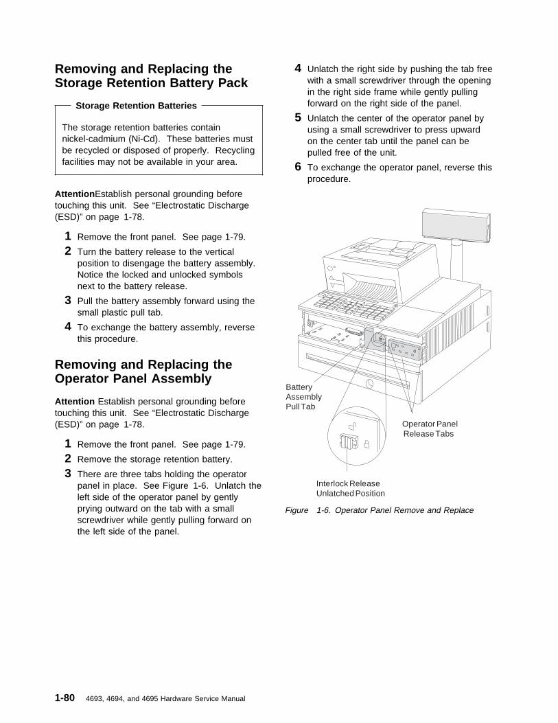
Removing and Replacing theStorage Retention Battery Pack
Storage Retention Batteries
The storage retention batteries containnickel-cadmium (Ni-Cd). These batteries mustbe recycled or disposed of properly. Recyclingfacilities may not be available in your area.
Attention Establish personal grounding beforetouching this unit. See “Electrostatic Discharge(ESD)” on page 1-78.
1 Remove the front panel. See page 1-79.
2 Turn the battery release to the verticalposition to disengage the battery assembly.Notice the locked and unlocked symbolsnext to the battery release.
3 Pull the battery assembly forward using thesmall plastic pull tab.
4 To exchange the battery assembly, reversethis procedure.
Removing and Replacing theOperator Panel Assembly
Attention Establish personal grounding beforetouching this unit. See “Electrostatic Discharge(ESD)” on page 1-78.
1 Remove the front panel. See page 1-79.
2 Remove the storage retention battery.
3 There are three tabs holding the operatorpanel in place. See Figure 1-6. Unlatch theleft side of the operator panel by gentlyprying outward on the tab with a smallscrewdriver while gently pulling forward onthe left side of the panel.
4 Unlatch the right side by pushing the tab freewith a small screwdriver through the openingin the right side frame while gently pullingforward on the right side of the panel.
5 Unlatch the center of the operator panel byusing a small screwdriver to press upwardon the center tab until the panel can bepulled free of the unit.
6 To exchange the operator panel, reverse thisprocedure.
BatteryAssemblyPull Tab
Interlock ReleaseUnlatched Position
Operator PanelRelease Tabs
Figure 1-6. Operator Panel Remove and Replace
1-80 4693, 4694, and 4695 Hardware Service Manual

Removing and Replacing thePower Supply
Attention Establish personal grounding beforetouching this unit. See “Electrostatic Discharge(ESD)” on page 1-78.
1 Switch Ready mode OFF.
2 Disconnect the AC power cords from therear connector panel.
3 Remove the front panel. See page 1-79.
4 Remove the storage retention battery. Seepage 1-80.
5 Remove the operator panel. See page 1-80.
Note: Observe the routing of the diskettedrive cable, if present, to make exchangingthe power supply easier.
6 Disconnect the diskette drive cable, ifpresent, from the connector at the front ofthe logic tray. See Figure 1-7.
7 Turn the power supply retaining screw,located at the lower right front,counterclockwise 2 to 2 1/2 turns or until thelocking tab is fully out of the slot.
8 Pull the power supply toward the front andremove it from the terminal.
Note: It may be difficult to pull the powersupply toward the front since it is attached tothe rear connector panel. Try prying gentlyat the lower right corner to start the powersupply forward.
9 If the power supply is to be exchanged witha new one, remove the diskette drive, ifpresent, from the power supply. See page1-82. Also, remove the fan and plenum.See page 1-82.
10 To exchange the power supply, reverse thisprocedure.
Note: When exchanging the power supply,you must push it inward with enough force toovercome the resistance provided by therear connector panel. Make sure that theretaining screw lug is aligned to thecorresponding slot in the frame.
Figure 1-7. Power Supply Remove and Replace
Chapter 1. Start Here for 4693 Problems 1-81

Removing and Replacing theDiskette Drive
1 Remove the power supply. See page 1-81.
2 Lift the diskette drive latch on the left side ofthe power supply and slide the drive to theright until it disengages. See Figure 1-8.
3 Remove the cable from the diskette drive.
Diskette Drive Replacement
1 With the power supply removed from theterminal, align the four guides on the bottomof the drive with the elongated holes in thetop of the power supply. Then slide thediskette drive to the left until the latchengages.
2 Route the diskette drive cable in the samemanner as it was when removed andconnect the cable.
3 Reinstall the power supply. See “Removingand Replacing the Power Supply” onpage 1-81.
Figure 1-8. Diskette Drive Remove and Replace
Removing and Replacing theCooling Fan and Plenum
1 Remove the power supply. See page 1-81.
2 Disconnect the fan connector from the powersupply by depressing the latch located ontop of the connector. See Figure 1-9.
3 Set the power supply on its side with theplenum facing upward.
4 Remove the plenum by pulling or pryingoutward on the two plenum release tabs untilthe plenum is disengaged from the powersupply.
5 Remove the fan from the plenum by pryingthe fan release tabs on the bottom of theplenum away from the fan housing until thefan can be removed.
6 To exchange the cooling fan and plenum,reverse this procedure.
Note: Make sure that the air flow arrows onthe plenum and fan are pointing in the samedirection.
Figure 1-9. Fan Remove and Replace
1-82 4693, 4694, and 4695 Hardware Service Manual

Removing and Replacing theLogic Tray
Attention Establish personal grounding beforetouching this unit. See “Electrostatic Discharge(ESD)” on page 1-78.
Note: If your terminal is attached to a store loopor PC baseband network, removing the logic traymay interrupt loop or network communications.
Store loop: Disconnect the store loop cable atthe store loop receptacle, at the wall receptacle orat the wiring panel before disconnecting from theadapter.
PC network baseband: Connect the basebandcables to the wrap plug after disconnecting fromthe adapter.
Ethernet and token-ring: These adapters shouldnot require a wrap plug. Check with the networkadministrator for any restrictions.
1 Disconnect any cables attached to optionadapters at the rear of the terminal. Notethe location of the cables to make it easier toreconnect them later.
2 Remove the front panel. See page 1-79.
3 Remove the storage retention battery. Seepage 1-80.
4 Disconnect the diskette drive cable from theconnector at the front of the logic tray. SeeFigure 1-10.
5 Turn the retaining screws located on eachside at the front of the logic traycounterclockwise approximately 2 1/2 turns.
6 Using the handle located at the front top ofthe tray, pull the logic tray forward until it canbe removed from the terminal.
7 To exchange the logic tray, reverse thisprocedure.
Note: When replacing the logic tray, youmust push it inward with enough force toovercome the resistance provided by therear connector panel. Make sure that theretaining screw lugs are aligned to thecorresponding slots in the frame.
Figure 1-10. Logic Tray Remove and Replace
Chapter 1. Start Here for 4693 Problems 1-83

Removing and Replacing theFixed Disk Drive
Attention Establish personal grounding beforetouching this unit. See “Electrostatic Discharge(ESD)” on page 1-78. If you are exchanging thefixed disk drive, be sure the original fixed disk isbacked up before beginning the removalprocedure.
1 Remove the logic tray. See page 1-83.
2 Disconnect the fixed disk cable from thesystem board.
3 Depress the levers on each side of the fixeddisk drive and pull the drive forward until it isfree from the logic tray.
Note: The fixed disk can be installed in twodifferent locations. Take note of the fixeddisk location (left or right position whenviewed from the front). If only one drive ispresent, it must be installed in the leftposition.
4 To exchange the fixed disk, reverse thisprocedure.
After the drive has been installed completely,the system partition must be recreated onthe new fixed disk. This requires the use ofthe backup copies of the system diskettes.
� Switch Ready mode ON with the backupreference diskette inserted in the diskettedrive. See “Loading the SystemPrograms” on page 1-71 for more detail.
� At the MAIN MENU, select STARTUTILITIES.
� At the UTILITY MENU, selectBACKUP/RESTORE SYSTEMPROGRAMS.
� At the BACKUP/RESTORE MENU,select RESTORE THE SYSTEMPARTITION.
� Follow the instructions that aredisplayed.
� When the system partition creation iscomplete, run the tests on the fixed diskto verify correct operation. See “Test
Procedure Using System Programs” onpage 1-75.
The 4693 Models 741 and 3W1 use fixed disksthat enable 32-bit addressing. One or twooptional fixed disks can be installed in the 4693Models 741 and 3W1.
Note: The fixed disk comes from the factory withthe jumper in the primary disk location. Wheninstalling two fixed disks the jumper on thesecondary fixed disk needs to be moved from theprimary disk location to the secondary disklocation. A dual cable is required.
1-84 4693, 4694, and 4695 Hardware Service Manual

Removing and Replacing anOption Adapter
Non-replaceable Lithium Battery inside unit.
1 Remove the logic tray. See page 1-83.
2 Note which slot the option adapters areplugged into.
3 Loosen the retaining screw holding theadapter at the rear connector panel.
4 Remove the option adapter by sliding it outto the side.
5 To exchange an option adapter, reverse thisprocedure.
Notes:
a. You may need to run Auto Configuration.
b. Each Ethernet, token-ring, and PCnetwork baseband adapter has a uniqueadapter address. When one of these isexchanged, the new adapter's addressmust be defined to the network serversoftware. If you do not know what thenew adapter's address is, see “How ToRetrieve Network Remote Program Load(RPL) Messages” on page 1-9 andrecord the AA: nnnnnnnnnnnn message.
Removing and Replacing MemoryModules
There are two memory module connectors on theterminal system board.
1 Remove the logic tray. See page 1-83.
2 If your terminal has an option adapter that isinstalled over the top of the memorymodules, the option adapter must beremoved.
3 Push the memory module retainers outwardsimultaneously until they release the module.See Figure 1-12.
4 Lift the module from the memory moduleconnector.
5 To exchange a memory module, reverse thisprocedure.
Figure 1-11. Logic Tray Components
Figure 1-12. Memory Module Remove and Replace
Chapter 1. Start Here for 4693 Problems 1-85

Removing and Replacing theTerminal System Board
1 Remove the logic tray. See page 1-83.
2 Note their locations and remove any optioncards that are present. See page 1-85.
3 Remove the bus adapter, if present, byremoving the bus adapter retainer andunplugging it from the system board.
4 Remove the fixed disk (if present).
5 Remove the two screws located near thecenter of the system board adjacent to thebus adapter socket.
Note: The 4693-xx2 has no bus adaptersocket. However, the location of the screwsthat hold the system board is obvious whenyou look at the board.
6 Disconnect the speaker connector.
7 Move the system board forward until theslots in the edge of the board align with thetabs in the frame. Then lift the board out ofthe tray. See Figure 1-13.
8 If you are exchanging the system board, thereplacement board is not supplied withmemory installed. Therefore, you mustremove the memory modules from the boardbeing exchanged and install them on thereplacement board. See Figure 1-11 onpage 1-85 for the memory module locations.
Notes:
a. Only the 4693-xx1 models have memorymodules on the board.
b. Non-replaceable Lithium Battery insideunit.
9 To exchange the system board, reverse thisprocedure.
10 The EC number is located on the left edgeof the system board near the rear of theboard. Record the EC number of thereplacement system board. This number isneeded later to enter into vital product data.
11 To eliminate the possibility of a configurationproblem with the new system board, youshould reset the configuration record. See
“Resetting Configuration and the TerminalLoad” on page 1-76. This procedure leadsyou through configuring the terminal andcreating a new configuration record.
12 After configuration is complete, you maywant to run some other utilities or test theterminal. See “Utilities Procedure UsingSystem Programs” on page 1-75 and “TestProcedure Using System Programs” onpage 1-75.
13 Go to Appendix E, “Collecting Vital ProductData for the 4693” on page E-1 and enterthe EC number of the system board.
Figure 1-13. System Unit Components
Removing and Replacing theSpeaker
1 Remove the terminal system board. Seepage 1-86.
2 Release the speaker from its retainer andremove it from the base.
3 To exchange the speaker, reverse thisprocedure.
Removing and Replacing theRear Cover
1 Open the rear cover by pressing on the rearcover buttons.
2 Press the two latching tabs located on the
1-86 4693, 4694, and 4695 Hardware Service Manual

top of the rear cover to disengage it from thetop cover. See Figure 1-14 on page 1-87.
3 To exchange the rear cover, reverse thisprocedure.
Removing and Replacing theRear Connector Panel
1 Switch Ready mode OFF.
2 Open the rear cover and disconnect the ACpower cords from the rear connector panel.
3 Remove the logic tray. See page 1-83.
Note: You only have to slide the logic trayto the front far enough to disconnect it fromthe rear connector panel.
4 Remove the power supply. See page 1-81.
Note: You only have to slide the powersupply to the front far enough to disconnectit from the rear connector panel.
5 Disconnect all remaining cables attached tothe rear of the 4693.
Note: Mark the location of each cable tomake it easier to reconnect when finished.
6 Remove the rear cover button on the left(facing the rear). This is done bycompressing the button retainer tabs on theinside of the button with your fingers whilesliding the button outward. Notice theposition of the button when you remove it. Itmust go back in the same position.
7 Remove the six screws that secure the rearconnector panel.
8 Pull the panel straight back approximately 1inch until the locator pins are cleared.
Note: You cannot see the locator pins, soyou must estimate the distance.
9 Pivot the left end (facing the rear) of the rearconnector panel outward so that it clears theside cover. This is a very tight fit, so youmay have to flex the side cover slightlyoutward. See Figure 1-15.
10 To exchange the rear connector panel,reverse this procedure.
Figure 1-14. Rear and Side Covers
Figure 1-15. Rear Connector Panel
Chapter 1. Start Here for 4693 Problems 1-87

Removing and Replacing theInput/Output Devices
1 Switch Ready mode OFF.
2 Open the rear cover by pressing inward onthe release buttons located at the rear of theside covers.
3 Disconnect the AC power cords from therear connector panel.
4 Disconnect all cables attached to the I/Odevices.
Note: Mark the location of each cable tomake it easier to reconnect when finished.
5 On an integrated terminal the I/O devicesare locked into the top cover by lugs locatedunder the devices. See Figure 1-16. Thelocking lever for these is located on the leftside (from the front) of the top cover. Pullthis lever outward to unlock the devices.Once unlocked, the printer can be lifted upand out of the top. The keyboard must bepushed slightly to the rear and then lifted upand out.
6 To exchange the I/O devices, reverse thisprocedure and be sure to push the lockinglever inward to lock the devices into the topcover.
Figure 1-16. I/O Device Removal
1-88 4693, 4694, and 4695 Hardware Service Manual

Removing and Replacing the TopCover
1 Switch Ready mode OFF.
2 Disconnect the AC power cords from therear connector panel.
3 Remove the rear cover. See page 1-86.
4 Remove the I/O devices from the top of theterminal. See page 1-88.
5 Disengage the cover from the terminal andlift off.
Note: This may require the use of ascrewdriver to gently pry at the coverlatching points. See Figure 1-17.
6 To exchange the top cover, align the coverat the latching points and reverse thisprocedure.
Removing and Replacing theSide Covers
1 Switch Ready mode OFF.
2 Disconnect the AC power cords from therear connector panel.
3 Remove the front panel. See page 1-79.
4 Remove the I/O devices from the top of theterminal.
5 Remove the rear cover. See page 1-86.
6 Remove the top cover from the top of theterminal.
7 From the rear of the terminal, press thelatching tabs on the inside rear of each sidecover while pushing the cover forward until itbecomes disengaged. See Figure 1-15 onpage 1-87.
8 To exchange the side covers, reverse thisprocedure.
Figure 1-17. Top Cover
Chapter 1. Start Here for 4693 Problems 1-89

Removing and Replacing theKeylock Insert
1 Switch Ready mode OFF.
2 Disconnect the AC power cords from therear connector panel.
3 See Figure 1-18 for identification of the lockpieces.
4 Unlock the keylock.
5 Insert the lock installation-removal key (B)fully into the lock insert (E).
Note: The installation-removal key isshipped with the store controller.
6 Pivot the key slightly downward while pullingthe lock insert out of the cylinder (F) until theinsert is disengaged from the cylinder.
7 When exchanging the lock insert, it fits allthe way into the lock cylinder only when theslot in the bottom of the cylinder and the lugon the end of the insert are both inalignment. If necessary, insert the alignertool (A) into the lock cylinder and rotate ituntil you feel it engage the slot at the bottomof the cylinder. Then turn the aligner tooluntil the arrow points to the left.
8 Remove the key that came with the new lockinsert.
9 Push the brass installation-removal key intothe lock insert. Be sure the key is FULLYINSERTED.
10 With the brass installation-removal key still inthe lock insert, push the lock insert fully intothe lock cylinder.
11 Hold the insert in place with your finger andremove the installation-removal key.
12 Test the lock using the keys that came withthe insert to be sure that the lock operatescorrectly.
Removing and Replacing theBlank Keylock Insert
1 Switch Ready mode OFF.
2 Disconnect the AC power cords from therear connector panel.
See Figure 1-18 for identification of the lockpieces.
Note: The blank lock insert handle (C) isshipped with the store controller.
3 Insert the blank keylock insert handle intothe blank keylock cylinder (D).
4 Using the blank keylock insert handle, turnthe locking screw counterclockwise until theinsert can be removed from the cylinder.
5 When exchanging the blank lock insert, theinsert has a lug on one end that must bealigned with the slot in the bottom of the lockcylinder. Hold the blank lock insert so thatthe lug is aligned with the slot.
6 Push the blank lock insert into the emptylock cylinder until it is flush with the top ofthe lock cylinder.
7 Use the blank lock insert handle to turn thelocking screw clockwise until it reaches thebottom of the hole. Do not overtighten.
Figure 1-18. Keylock Removal and Replacement
1-90 4693, 4694, and 4695 Hardware Service Manual

Removing the Power-OnPassword:Attention Establish personal grounding beforetouching this unit. See “Electrostatic Discharge(ESD)” on page 1-78.
Note: This procedure should only be used whenservicing a terminal that has an active, unknown,power-on password.
1 Switch Ready mode OFF.
2 Disconnect the AC power cords from therear connector panel.
3 Follow the instructions to remove the logictray. See page 1-83.
Note: You only have to pull the logic trayout far enough to gain access to the jumperwhich is located on the front left corner ofthe logic board when viewed from the front.See Figure 1-19 or Figure 1-20 (for model3W1).
4 The jumper is connected between the centerpin and one of the outside pins. Move thejumper so that it is connected between thecenter pin and the pin on the opposite endfrom the one it is currently connected to.
The system detects the change during powerup and removes the password. You do notneed to move the jumper back to its originalposition.
To reactivate the password, the user mustload the system programs and select STARTUTILITIES from the main menu. Then selectSET PASSWORD and follow the instructionsthat are displayed.
Figure 1-19. Password Jumper
Figure 1-20. Password Jumper (Model 3W1)
Chapter 1. Start Here for 4693 Problems 1-91

Removing and Replacing anExtended Duration Battery
1 Remove the power supply. See page 1-81.
2 Remove the battery and plenum assemblyfrom the power supply.
3 Remove the cooling fan from the plenum.
4 Install the new battery and plenum assemblyonto the power supply by aligning the tabs atthe top of the plenum with the cutouts in thetop of the power supply. Pivot the assemblydownward while aligning the locating tabs atthe bottom of the plenum with the cutouts inthe side of the power supply. Pressdownward until the plenum snaps into place.See Figure 1-21.
5 Install the fan into the plenum so that the airflow arrows on the plenum and the fanhousing are pointing in the same direction.Push the top of the fan in first, then snap itin at the bottom.
Note: The air flow direction is into thepower supply from the logic tray area.
6 Plug the fan cable into the connector on thepower supply.
7 Reinstall the power supply. See page 1-81.
Note: Be sure to install the new interlockassembly supplied with the battery andplenum assembly.
Storage Retention Batteries
Return used Ni Cd (storage retention)batteries to IBM for disposal.
Figure 1-21. Installing the Plenum and BatteryAssembly
Figure 1-22. Installing the Fan
1-92 4693, 4694, and 4695 Hardware Service Manual

4693 Model 741 Processor Jumper InformationAttention Establish personal grounding before touching this unit. See “Electrostatic Discharge (ESD)” onpage x.
Note: This procedure should only be used when changing the main processor from a 486SX to any otherprocessor.
1 Switch Ready mode OFF.
2 Disconnect the AC power cords from therear connector panel.
3 Remove the logic tray. See page 1-83.
Note: You only have to pull the logic trayout far enough to gain access to theprocessor jumper.
4 The processor jumper is connected betweenthe center pin and one of the outside pins.Move the jumper so that it is connectedbetween the center pin and the pin on theopposite end from the one it is currentlyconnected to.
The system detects the change duringPOST. You do not need to move the jumperback to its original position.
Chapter 1. Start Here for 4693 Problems 1-93

Removing the Power-On Password
Attention Establish personal grounding before touching this unit. See “Electrostatic Discharge (ESD)” onpage x.
Note: This procedure should only be used when servicing a terminal that has an active, unknown,power-on password.
1 Switch Ready mode OFF.
2 Disconnect the AC power cords from therear connector panel.
3 Remove the logic tray. See page 1-83.
Note: You only have to pull the logic trayout far enough to gain access to the jumper.See Figure 1-23 and Figure 1-24.
4 The password jumper is connected betweenthe center pin and one of the outside pins.Move the jumper so that it is connectedbetween the center pin and the pin on theopposite end from the one it is currentlyconnected to.
The system detects the change during POSTand removes the password. You do notneed to move the jumper back to its originalposition.
To reactivate the password, the user mustload the system programs and select STARTUTILITIES from the main menu. Then selectSET PASSWORD and follow the instructionsthat are displayed.
Figure 1-23. 4693 Model 741 Password JumperLocation
Figure 1-24. 4693 Model 3W1 Password JumperLocation
1-94 4693, 4694, and 4695 Hardware Service Manual

Chapter 2. Start Here for 4694 Problems
DANGER
Never work on equipment or connect or disconnect signal cables during periods oflightning activity.
CAUTION:For your safety, connect equipment requiring electrical power to a properly wired and groundedoutlet.
Problems with the 4694 can be caused by both software errors or hardware failures. This chaptercontains troubleshooting information to help you determine the cause of a problem and how to solve it.
Use Table 2-1 to determine the page number to go to by cross-referencing the task to be performed.
Table 2-1. 4694 Task Information
TASK Page
Start 4694 Problem Determination 2-2
Look up a 4694 message or beep code 2-5
Look up a 4694 symptom 2-3
Run tests on a 4694 point-of-sale terminal 2-8
Remove and exchange a 4694 Model 001, 004, or 024 FRU 2-11
Remove and exchange a 4694 Model 041, 044, or 144 FRU 2-17
Perform a maintenance inspection B-1
Perform preventive maintenance C-1
Special tools you may need D-1
Copyright IBM Corp. 1993, 1995 2-1

4694 Problem Determination
Begin each service call by checking all items in the preliminary checklist. If, after performing all the steps,a problem still exists, see the “4694 Symptom Table” on page 2-3 to continue problem determination.
Preliminary Checklist
1 Observe the power light (behind the door on the front). If it is not ON, go to “4694 Symptom Table”on page 2-3.
2 Ensure that the I/O device cables are securely and correctly connected.
3 Ensure that the I/O devices that have their own power switch are connected to a good AC poweroutlet and are powered ON.
4 Ensure the contrast and brightness controls on the video display (if attached) are set correctly.
5 Ensure that the correct diskette is inserted.
6 Ensure that all hardware devices installed (such as a memory module, feature card, printer, ormouse) are connected correctly and securely.
7 POWER OFF then ON and listen for beep(s) at the completion of POST. Indications of a successfulcompletion of POST are:
� An OK is displayed on all point-of-sale displays� Point-of-sale keyboards beep 3 times� The point-of-sale printer prints a test pattern� System unit beeps one time.
If none of the successful POST indications occur on any I/O device, the 4694 system unit is failing.See “4694 Symptom Table” on page 2-3.
If, for example, the POS display fails to display OK but the POS keyboard does beep 3 times, this isan indication that the POST was successful and the display and/or cable is failing.
If the problem still exists after performing these preliminary checks, record any error codes. See“POST/Beep Messages” on page 2-5 for a list of error codes and messages. If you have no errormessage, see “4694 Symptom Table” on page 2-3.
2-2 4693, 4694, and 4695 Hardware Service Manual

4694 Symptom Table
If the problem is... Here’s what to do...
The power light (behind the doorin the front) is OFF.
� Check that the AC power cord is plugged into both the wall outlet and theback of the terminal.
� Check that the terminal is powered on.� Ensure that AC power is present at the wall outlet.� Disconnect all attached devices and feature cards to determine if one is
overloading the power supply. If the power light returns, reconnect them oneat a time to determine the failing FRU.
� Exchange the power supply. See page 2-14 for Models 001, 004, or 024 orsee page 2-19 for Models 041, 044, or 144.
� Exchange the system board. See page 2-15 for Models 001, 004, or 024 orsee page 2-20 for Models 041, 044 or 144.
Terminal is not working at all. � POWER OFF, wait 5 seconds, then switch power ON. Check that thepower light on the front panel is ON. Look for a POST error message andlisten for a beep at the completion of POST.
� Check for a blown fuse, tripped circuit breaker, or power failure. (First, checkat the fuse or breaker box, then inside the terminal.)
� Check that all cables are securely connected to the terminal.� Check that the correct software is installed.
No beep occurs after POST.This symptom applies only if noPOS keyboard is attached. See“POS keyboard does not beepthree times after POST”.
� Check for messages displayed during POST.� Check that the power light on the front panel is ON.� Check that all memory modules and feature cards are installed correctly.� Exchange the system board. See page 2-15 for Models 001, 004, or 024 or
see page 2-20 for Models 041, 044, or 144.
POS keyboard does not beepthree times after POST.This symptom applies only if aPOS keyboard is attached. See“No beep after POST”.
� Check that the power light on the front panel is ON.� Check that all memory modules and feature cards are installed correctly.� Check for an OK displayed on the POS display (if attached) after POST. If
OK is not displayed, exchange the system board. See page 2-15 for Models001, 004, or 024 or see page 2-20 for Models 041, 044, or 144.
� Check for a printer test pattern printed on the POS printer (if attached) afterPOST. If no test pattern is printed, exchange the system board.
� Exchange the POS keyboard.
POS display does not displayOK after POST.This symptom applies only if aPOS display is attached.
� Check that the power light on the front panel is ON.� Check that all memory modules and feature cards are installed correctly.� Listen for three beeps from the POS keyboard (if attached) after POST. If
you do not hear three beeps, exchange the system board. See page 2-15for Models 001, 004, or 024 or see page 2-20 for Models 041, 044 or 144.
� Check for a printer test pattern printed on the POS printer (if attached) afterPOST. If no test pattern is printed, exchange the system board.
� Exchange the POS display.
POS printer does not print a testpattern after POST.This symptom applies only if aPOS printer is attached.
� Check that the power light on the front panel is ON.� Check that all memory modules and feature cards are installed correctly.� Listen for three beeps from the POS keyboard (if attached) after POST. If
you do not hear three beeps, exchange the system board.� Check for an OK displayed on the POS display (if attached) after POST. If
OK is not displayed, exchange the system board. See page 2-15 for Models001, 004, or 024 or see page 2-20 for Models 041, 044 or 144.
� Service the POS printer.
A beep sequence or acontinuous beep occurs afterPOST.
� See “POST/Beep Messages” on page 2-5 for beep sequences.� Check that all memory modules and feature cards are installed correctly.� See “POST/Beep Messages” on page 2-5 for explanation of POST
messages and beep codes.
Chapter 2. Start Here for 4694 Problems 2-3

If the problem is... Here’s what to do...
A POST error message isdisplayed.
Go to “POST/Beep Messages” on page 2-5.
Diskette does not load. � Make sure you are using the correct type of diskette and that it is formattedcorrectly.
� Ensure that the diskette is inserted into the drive correctly.� Try to read a known good diskette. If it works, the first diskette may be
defective.� Try loading the 4694 service diskette to test the diskette drive.� Exchange the diskette drive and cable. See page 2-13 for Models 001, 004,
or 024 or see page 2-18 for Models 041, 044, or 144.� Exchange the system board. See page 2-15 for Models 001, 004, or 024 or
see page 2-20 for Models 041, 044 or 144.
Cannot write information todiskette.
� Ensure that the diskette is formatted correctly.� Ensure that the diskette is not write protected.� Ensure that you are sending information to the correct drive.� Ensure that there is space on the diskette for the information. (Try using a
blank, formatted diskette.)� Try loading the 4694 service diskette to test the diskette drive.� Exchange the diskette drive and cable. See page 2-13 for Models 001, 004,
or 024 or see page 2-18 for Models 041, 044 or 144.� Exchange the system board. See page 2-15 for Models 001, 004, or 024 or
see page 2-20 for Models 041, 044 or 144.
One or more POS I/O devicesare failing.
� Ensure that the I/O devices are securely and correctly connected to the 4694system unit.
� If the device has its own power cord and power switch, ensure that it haspower and the power switch is ON.
� Try exchanging the failing device with a known good one (if available) to helpin isolating the failure.
� The keyboard, mouse, and printer use +5 V DC. Check the +5 V DC fuseinside the system unit.
– If the fuse is blown, exchange it and verify that it does not blow againimmediately.
– If the fuse blows again, disconnect the keyboard, mouse, and printerfrom the rear connector panel.
Note: The print head may be damaged when the +5 V DC fuse blows.Check the printer before completing the service call.
– If the fuse continues to blow with the devices disconnected, exchangethe system board.
– If the fuse does not blow with the devices disconnected, reconnect them,one at a time, to determine which is causing the fuse to blow.
� Load the 4694 service diskette to test the I/O devices.– If the scanner is failing, use the reference documentation that came with
the scanner.– If the keyboard attached to the 5 socket at the rear of the 4694 is
failing:- Move your fingers across the keys. Make sure no keys are stuck.- Make sure you are on a screen that allows typing. Some screens do
not.- Exchange the keyboard and cable.
– If the cash drawer, point-of-sale keyboard, or point-of-sale printer isfailing, use the Store Systems: Hardware Service Manual forPoint-of-Sale Input/Output Devices to service them.
– If the video display is failing, use the reference documentation that camewith the display.
2-4 4693, 4694, and 4695 Hardware Service Manual
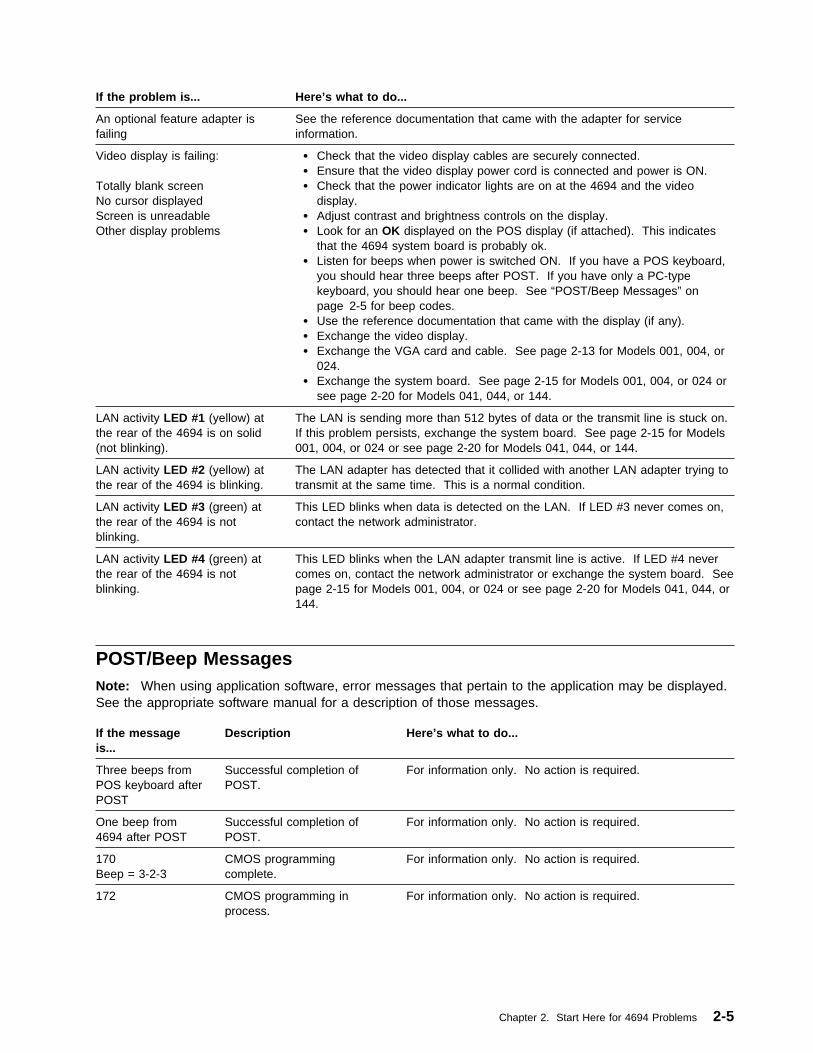
POST/Beep MessagesNote: When using application software, error messages that pertain to the application may be displayed.See the appropriate software manual for a description of those messages.
If the problem is... Here’s what to do...
An optional feature adapter isfailing
See the reference documentation that came with the adapter for serviceinformation.
Video display is failing: Totally blank screenNo cursor displayedScreen is unreadableOther display problems
� Check that the video display cables are securely connected.� Ensure that the video display power cord is connected and power is ON.� Check that the power indicator lights are on at the 4694 and the video
display.� Adjust contrast and brightness controls on the display.� Look for an OK displayed on the POS display (if attached). This indicates
that the 4694 system board is probably ok.� Listen for beeps when power is switched ON. If you have a POS keyboard,
you should hear three beeps after POST. If you have only a PC-typekeyboard, you should hear one beep. See “POST/Beep Messages” onpage 2-5 for beep codes.
� Use the reference documentation that came with the display (if any).� Exchange the video display.� Exchange the VGA card and cable. See page 2-13 for Models 001, 004, or
024.� Exchange the system board. See page 2-15 for Models 001, 004, or 024 or
see page 2-20 for Models 041, 044, or 144.
LAN activity LED #1 (yellow) atthe rear of the 4694 is on solid(not blinking).
The LAN is sending more than 512 bytes of data or the transmit line is stuck on.If this problem persists, exchange the system board. See page 2-15 for Models001, 004, or 024 or see page 2-20 for Models 041, 044, or 144.
LAN activity LED #2 (yellow) atthe rear of the 4694 is blinking.
The LAN adapter has detected that it collided with another LAN adapter trying totransmit at the same time. This is a normal condition.
LAN activity LED #3 (green) atthe rear of the 4694 is notblinking.
This LED blinks when data is detected on the LAN. If LED #3 never comes on,contact the network administrator.
LAN activity LED #4 (green) atthe rear of the 4694 is notblinking.
This LED blinks when the LAN adapter transmit line is active. If LED #4 nevercomes on, contact the network administrator or exchange the system board. Seepage 2-15 for Models 001, 004, or 024 or see page 2-20 for Models 041, 044, or144.
If the messageis...
Description Here’s what to do...
Three beeps fromPOS keyboard afterPOST
Successful completion ofPOST.
For information only. No action is required.
One beep from4694 after POST
Successful completion ofPOST.
For information only. No action is required.
170Beep = 3-2-3
CMOS programmingcomplete.
For information only. No action is required.
172 CMOS programming inprocess.
For information only. No action is required.
Chapter 2. Start Here for 4694 Problems 2-5

If the messageis...
Description Here’s what to do...
173 CMOS programming isunsuccessful.
Try again. If failure persists:
� Try creating a new diskette.� Exchange the diskette drive and cable. See page 2-13
for Models 001, 004, or 024 or see page 2-18 forModels 041, 044, or 144.
� Exchange the system board. See page 2-15 for Models001, 004, or 024 or see page 2-20 for Models 041, 044,or 144.
174Beep = 3-3-2
CMOS is corrupt. Switch POWER OFF then ON again. Usually CMOSrecovers successfully. Otherwise, exchange the systemboard. See page 2-15 for Models 001, 004, or 024 or seepage 2-20 for Models 041, 044 or 144.
990Beep = 1-1-1
BIOS programming iscomplete.
For information only. No action is required.
997Beep = 3-2-3
BIOS programming isunsuccessful.
Try again. If failure persists:
� Try creating a new diskette.� Exchange the diskette drive and cable. See page 2-13
for Models 001, 004, or 024 or see page 2-18 forModels 041, 044, or 144.
� Exchange the system board. See page 2-15 for Models001, 004, or 024 or see page 2-20 for Models 041, 044or 144.
998 BIOS programming is inprocess.
For information only. No action is required.
999Beep = 1-1-4
BIOS is corrupted. Exchange the system board or call your support organizationfor assistance in reprogramming the BIOS. See page 2-15for Models 001, 004, or 024 or see page 2-20 for Models041, 044 or 144.
Blank videoBeep = 3-2-4
Keyboard controller testfailed during POST.
Check the +5 V DC fuse on the system board.
� If the fuse is OK, exchange the system board.� If the fuse is blown, see “4694 Symptom Table” on
page 2-3.
Blank videoBeep = 1-1-1(immediately afterpowering ON)
POST failure occurred. Ensure that the memory modules are connected correctlyand securely.
� If the memory modules are connected OK, exchange thesystem board. See page 2-15 for Models 001, 004, or024 or see page 2-20 for Models 041, 044, or 144.
� Exchange the memory modules. See page 2-16 forModels 001, 004, or 024 or see page 2-20 for Models041, 044 or 144.
Beep = 3-4-1 VGA card not found. � If a video display is attached, ensure that a VGA card ispresent. See Figure 2-3 on page 2-13.
� If a video display is attached and the VGA card ispresent, exchange the VGA card. See page 2-13 forModels 001, 004, or 024.
� If no video display is attached, you must runconfiguration to remove VGA from the configurationrecord.
2-6 4693, 4694, and 4695 Hardware Service Manual

If the messageis...
Description Here’s what to do...
Stops with U001displayed (on POSdisplay)
Display is not communicatingon device channel.
� Ensure that the memory modules are connectedcorrectly and securely.
� POWER OFF then ON and listen for beep(s) at thecompletion of POST. A single beep indicates asuccessful completion. No beep(s) or more than oneindicates a failure. If a failure is indicated, see “4694Symptom Table” on page 2-3.
� Disconnect all POS devices except the display, one at atime, to determine if one is causing the failure.
� Exchange the system board. See page 2-15 for Models001, 004, or 024 or see page 2-20 for Models 041, 044,or 144.
� Exchange the POS display.
Stops with U003displayed (on POSdisplay)
Display is communicating ondevice channel but noprogram loading occurs fromthe boot device (diskette,fixed disk, LAN).
� Try booting a known good diskette.� Ensure that the correct diskette is in the diskette drive.� Exchange the system board. See page 2-15 for Models
001, 004, or 024 or see page 2-20 for Models 041, 044,or 144.
Chapter 2. Start Here for 4694 Problems 2-7

Testing the 4694
The 4694 service diskette (SX27-3933) provides menu driven tests and utilities for testing and isolating afailing 4694 FRU. It is intended for use by trained service personnel. This diskette is not shipped withyour terminal, but can be purchased from IBM.
When the 4694 is booted with the service diskette, point-of-sale devices are automatically configured. Youshould follow any displayed instructions. When the MAIN MENU appears you can select the desired testor utility.
Service Diskette Menus
The menus appear differently depending upon the type of devices attached. If a video display is attached,the menus appear with all possible menu items displayed together. If no video display is attached, eachmenu is displayed, one menu item at a time on the top line of the display. Your choice of responses isdisplayed on the bottom line of the display. Depending upon your response, the program either goes tothe next item in the menu, goes to another menu, or guides you through the choice that you selected.
The TEST menus contain only those devices that are attached and configured.
The service diskette menu flow is as follows:
2-8 4693, 4694, and 4695 Hardware Service Manual

Point-of-Sale Device Tests
A test is provided for each of the point-of-sale devices such as:
� Cash drawer port � Customer display � Keyboard � Printer � Scanner
System Unit Tests
A test is provided for each of the system unit devices such as:
� CPU sub-system � System memory � Mouse port� Serial (RS232) port
� VGA sub-system � PCMCIA sub-system � PC Printer � Diskette drive� Fixed disk drive
Utilities
The following utilities are provided on the service diskette:
� Backup service diskette� Set system date and time
Viewing Configuration
There are two view configuration selections:
� View system configuration� View POS configuration
When you view system configuration, the following information is displayed:
� CPU type� DRAM RAM size� ASIC I/O usage� NVRAM address usage� SIO IRQ level� Shared memory address usage� Flash memory write enable/disable� Fixed disk drive
� Diskette drive
� LAN boot ROM address� LAN adapter IRQ� LAN adapter usage� LAN IEEE ID� PCMICA adapter installed/not installed� PCMICA adapter address usage� VGA card installed/not installed� VGA address usage� VGA monitor type selection
Chapter 2. Start Here for 4694 Problems 2-9

System Configuration Menus
When you start the system configuration program, the first menu you see is “STANDARD SYSTEMPARAMETERS”. Many of these values are set automatically by the program when you power on theterminal and are not configurable. In the above menu, you can change the system date and time, andenable or disable the COM ports.
Using the cursor keys, select the option that you want to change. Press the + or − keys to change thevalue. If you want more help, press the F1 key.
Press the PgDn key to see the next page of the system configuration menu, “BOOT SEQUENCE”. Allitems on the second menu are configurable. BOOT SOURCE refers to the order in which POST looks fora valid boot load. A standard PC looks first at drive A; then at drive C. Most PCs typically have no thirdboot source. The 4694 does have a third option since it can perform a remote program load (RPL) off ofa LAN using the IBM Ethernet Remote Program Load protocol.
Note: For the 4694 Model 144, all RPL protocol settings enable the RPL ROM into adapter addressrange C8000-CFFFF. If you are not using the RPL protocol option, select the LAN Adapter option setting.This disables the RPL ROM and makes address range C8000-CFFFF available for other adapters to use.To invoke the system program, switch power ON. Then press F2, when prompted by the display.
The POS adapter options refer to memory addresses and interrupt levels used by the integrated POSadapter. Unless you are using non-IBM POS device drivers, you should not change these values.
Press ESC to exit the system configuration menus (and create the system configuration diskette if usingthe CSETUP program).
2-10 4693, 4694, and 4695 Hardware Service Manual

4694 Models 001, 004, and 024 Removals and Replacements
These procedures provide step-by-step instructions for removing and replacing field replaceable units(FRUs) for the 4694 Models 001, 004, and 024. For the procedures for 4694 Models 041, 044, and 144see “4694 Models 041, 044, and 144 Removals and Replacements” on page 2-17. These procedures aredesigned for a trained service person.
Electrostatic Discharge (ESD)
Attention ESD damage can occur when there is a difference in charge between the part, the product, andthe service person. No damage occurs if the service person and the part being installed are at the samecharge level.
ESD Damage Prevention
Anytime a service action involves physical contact with logic cards, modules, back-panel pins, or otherESD sensitive (ESDS) parts, the service person must be connected to an ESD common ground point onthe product through the ESD wrist strap and cord.
The ESD ground clip can be attached to any frame ground, ground braid, green wire ground, or the roundground prong on the AC power plug. Coax or connector outside shells can also be used.
Handling Removed Cards
Logic cards removed from a product should be placed in ESD protective containers. No other objectshould be allowed inside the ESD container with the logic card. Attach tags or reports that mustaccompany the card to the outside of the container.
Chapter 2. Start Here for 4694 Problems 2-11

Removing and Replacing theCovers
1 POWER OFF the 4694 and any attacheddevices that have a power ON/OFF switch.
2 Disconnect the 4694 power cord from theelectrical outlet.
3 Disconnect the power cord for any externaldevices from the electrical outlet.
4 Remove the rear modesty cover by sliding itupward.
5 Take note of the cable connections for all I/Odevices before disconnecting them.
6 Disconnect and remove the keyboard,printer, display, and any other I/O devicesfrom the top of the system unit.
7 Press down on the spring catch at the rear,under side of the top cover and slide thecover to the rear until it stops.
8 Flex the sides of the top cover outward andpull upward until the cover is free.
9 To remove the top metal cover, remove themounting screw and lift the cover to an angleof about 30 degrees. The cover can now bedisengaged from the base by moving thecover in the direction shown in Figure 2-1.
10 To exchange the covers, reverse thisprocedure.
Figure 2-1. Cover Removal
2-12 4693, 4694, and 4695 Hardware Service Manual

Removing and Replacing theDiskette Drive or Fixed Disk Drive
1 Remove the covers. See page 2-12.
2 Remove the spline from the chassis. SeeFigure 2-5 on page 2-14.
3 Note of the plug location of the cables at therear of the drives and disconnect them. Itmay help to disconnect the flat cables at thesystem board also.
4 Release the locking catch on the file bucketby using a flat blade screwdriver as shown inFigure 2-2. At the same time, slide the filebucket to the rear until the bucket clears theguides.
5 Once the guides have been cleared, lift thefile bucket up and out of the chassis.
6 Remove the four screws that retain the drivein the file bucket and slide the drive out.
7 To exchange the drive, reverse thisprocedure.
Figure 2-2. Diskette and Fixed Disk Drive
Removing and Replacing theVGA Card
Attention Establish personal grounding beforetouching this unit. See “Electrostatic Discharge(ESD)” on page 2-11.
1 Remove the covers. See page 2-12.
2 Remove any feature cards.
3 Remove the two screws that hold the centralspline and remove it.
4 If the PCMCIA card is present, remove themounting screw.
5 Remove the riser card and PCMCIA card (ifpresent) together from the system board.
6 Disconnect the VGA cable from the VGAcard.
7 Lift and remove the VGA card from thesystem board.
8 To exchange the VGA card, reverse thisprocedure.
Figure 2-3. VGA Card Removal
Chapter 2. Start Here for 4694 Problems 2-13
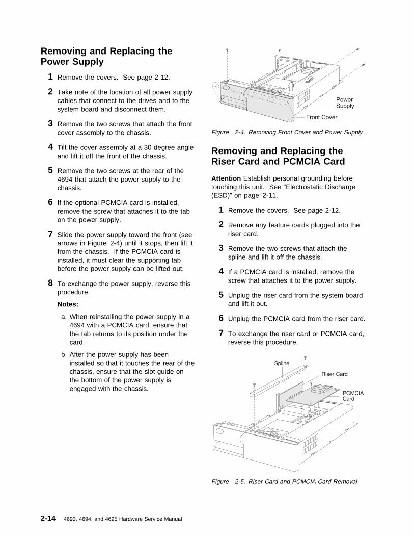
Removing and Replacing thePower Supply
1 Remove the covers. See page 2-12.
2 Take note of the location of all power supplycables that connect to the drives and to thesystem board and disconnect them.
3 Remove the two screws that attach the frontcover assembly to the chassis.
4 Tilt the cover assembly at a 30 degree angleand lift it off the front of the chassis.
5 Remove the two screws at the rear of the4694 that attach the power supply to thechassis.
6 If the optional PCMCIA card is installed,remove the screw that attaches it to the tabon the power supply.
7 Slide the power supply toward the front (seearrows in Figure 2-4) until it stops, then lift itfrom the chassis. If the PCMCIA card isinstalled, it must clear the supporting tabbefore the power supply can be lifted out.
8 To exchange the power supply, reverse thisprocedure.
Notes:
a. When reinstalling the power supply in a4694 with a PCMCIA card, ensure thatthe tab returns to its position under thecard.
b. After the power supply has beeninstalled so that it touches the rear of thechassis, ensure that the slot guide onthe bottom of the power supply isengaged with the chassis.
Figure 2-4. Removing Front Cover and Power Supply
Removing and Replacing theRiser Card and PCMCIA Card
Attention Establish personal grounding beforetouching this unit. See “Electrostatic Discharge(ESD)” on page 2-11.
1 Remove the covers. See page 2-12.
2 Remove any feature cards plugged into theriser card.
3 Remove the two screws that attach thespline and lift it off the chassis.
4 If a PCMCIA card is installed, remove thescrew that attaches it to the power supply.
5 Unplug the riser card from the system boardand lift it out.
6 Unplug the PCMCIA card from the riser card.
7 To exchange the riser card or PCMCIA card,reverse this procedure.
Figure 2-5. Riser Card and PCMCIA Card Removal
2-14 4693, 4694, and 4695 Hardware Service Manual
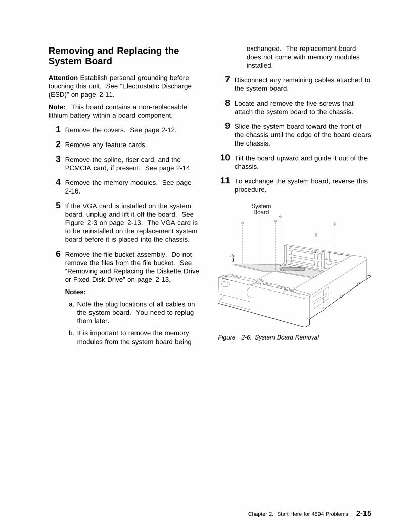
Removing and Replacing theSystem Board
Attention Establish personal grounding beforetouching this unit. See “Electrostatic Discharge(ESD)” on page 2-11.
Note: This board contains a non-replaceablelithium battery within a board component.
1 Remove the covers. See page 2-12.
2 Remove any feature cards.
3 Remove the spline, riser card, and thePCMCIA card, if present. See page 2-14.
4 Remove the memory modules. See page2-16.
5 If the VGA card is installed on the systemboard, unplug and lift it off the board. SeeFigure 2-3 on page 2-13. The VGA card isto be reinstalled on the replacement systemboard before it is placed into the chassis.
6 Remove the file bucket assembly. Do notremove the files from the file bucket. See“Removing and Replacing the Diskette Driveor Fixed Disk Drive” on page 2-13.
Notes:
a. Note the plug locations of all cables onthe system board. You need to replugthem later.
b. It is important to remove the memorymodules from the system board being
exchanged. The replacement boarddoes not come with memory modulesinstalled.
7 Disconnect any remaining cables attached tothe system board.
8 Locate and remove the five screws thatattach the system board to the chassis.
9 Slide the system board toward the front ofthe chassis until the edge of the board clearsthe chassis.
10 Tilt the board upward and guide it out of thechassis.
11 To exchange the system board, reverse thisprocedure.
Figure 2-6. System Board Removal
Chapter 2. Start Here for 4694 Problems 2-15

Removing and Replacing MemoryModules
Attention Establish personal grounding beforetouching this unit. See “Electrostatic Discharge(ESD)” on page 2-11.
1 Remove the covers. See page 2-12.
2 Remove any full length feature cards thatcover the memory modules.
3 Follow any special handling instructions thatcame with the memory modules.
4 Release the retainers for all the memorymodules, starting with the module closest tothe rear of the system board. They pivot tothe rear when released.
5 Remove the modules being exchanged.
6 To exchange the memory modules, reversethis procedure.
Notes:
a. Insert the memory modules into thesocket with the component side of themodule facing toward the front of thesystem board. Pivot all modules,starting with the one closest to the frontof the system board, toward the frontuntil they latch into the retainers.
b. If only two modules are installed, theymust be installed in the two slots closestto the front of the 4694.
Figure 2-7. Memory Modules
There are four 30-pin memory module sockets onthe 4694 system board. This makes two memorybanks (Bank 0 and Bank 1). The 4694 comeswith two 1 MB or two 4 MB memory modulesinstalled. This fills two of the slots, SM1 and SM2(Bank 0). You can install the followingcombinations of memory modules on the 4694Models 001, 004, and 024:
Table 2-2. Valid Memory Module Combinations –Models 001, 004, 024
TotalMemory
Bank 0SM1 SM2
Bank 1SM3 SM4
2 MB 1 1 0 0
4 MB 1 1 1 1
8 MB 4 4 0 0
16 MB 4 4 4 4
2-16 4693, 4694, and 4695 Hardware Service Manual

4694 Models 041, 044, and 144 Removals and ReplacementsRemoving and Replacing theFront Panel and Logic Tray
Attention Establish personal grounding beforetouching this unit. See “Electrostatic Discharge(ESD)” on page 2-11.
1 POWER OFF the 4694 and any attacheddevices that have a power ON/OFF switch.
2 Disconnect the 4694 power cord from therear of the 4694.
3 Disconnect the power cord for any externaldevices from the electrical outlet.
4 Disconnect all cables attached at the rear ofthe terminal. Note the location of the cablesto make it easier to reconnect them later.
5 To disengage the front panel, press thebuttons on each side at the front (one at atime) while gently pulling forward on eachside of the panel until both sides arereleased from the latches. Press the releaselatch (behind the front door) and pull thepanel off.
6 Pull up on the logic tray latch to release itand then pull the tray forward until it can beremoved from the terminal.
7 To replace the logic tray, reverse thisprocedure.
8 Reinstall the front panel.
Figure 2-8. Front Panel Removal
Figure 2-9. Logic Tray Removal
Chapter 2. Start Here for 4694 Problems 2-17

Removing and Replacing theDiskette Drive or Fixed Disk Drive
1 Remove the front panel and logic tray. Seepage 2-17.
2 Note of the plug location of the cables at therear of the drives and disconnect them.
3 Release the tabs on the drive to be removedand slide it to the rear until it can be liftedout of the chassis.
Note: When replacing the fixed disk, it mayhelp to remove the diskette drive first.
4 Remove the two screws from the bracketsattached to each side of the drive andremove the brackets.
5 Place the brackets onto the replacementdrive and install the two screws for eachbracket.
6 Slide the drive into position until it snaps intoplace.
7 Reconnect all cables.
8 Replace the logic tray and front panel.
Figure 2-10. Diskette and Fixed Disk Drive
2-18 4693, 4694, and 4695 Hardware Service Manual

Removing and Replacing thePower Supply
1 Remove the front panel and logic tray. Seepage 2-17.
2 Take note of the location of all power supplycables that connect to the drives and to thesystem board and disconnect them.
3 Remove the two screws at the rear of the4694 that attach the power supply to thechassis. See Figure 2-11.
4 Slide the power supply toward the front. SeeFigure 2-11. until it stops, then lift it fromthe chassis.
5 To exchange the power supply, reverse thisprocedure.
Note: After the power supply has beeninstalled so that it touches the rear of thechassis, ensure that the slot guide on thebottom of the power supply is engaged withthe chassis.
Figure 2-11. Removing the Power Supply
Chapter 2. Start Here for 4694 Problems 2-19
Removing and Replacing theRiser Card and PCMCIA Card
Attention Establish personal grounding beforetouching this unit. See “Electrostatic Discharge(ESD)” on page 2-11.
1 Remove the front panel and logic tray. Seepage 2-17.
2 Remove any feature cards plugged into theriser card.
3 Remove the two screws that attach thespline and lift it off the chassis. SeeFigure 2-11 on page 2-19.
4 If a PCMCIA card is installed, remove thescrew that attaches it to the rear panel.
5 Unplug the riser card from the system boardand lift it out.
6 Unplug the PCMCIA card from the riser card.
7 To exchange the riser card or PCMCIA card,reverse this procedure.
Removing and Replacing theSystem Board
Attention Establish personal grounding beforetouching this unit. See “Electrostatic Discharge(ESD)” on page 2-11.
Note: This board contains a non-replaceablelithium battery within a board component.
1 Remove the front panel and logic tray. Seepage 2-17.
2 Remove any feature cards.
3 Remove the spline, riser card, and thePCMCIA card (if present). See page 2-20.
4 Remove the memory modules. See page2-20.
Notes:
a. Note the plug locations of all cables onthe system board. You need to replugthem later.
b. It is important to remove the memorymodules from the system board being
exchanged. The replacement boarddoes not come with memory modulesinstalled.
5 Disconnect any remaining cables attached tothe system board.
6 Locate and remove the five screws thatattach the system board to the chassis.
7 Slide the system board toward the front ofthe chassis until the edge of the board clearsthe chassis.
8 Tilt the board upward and guide it out of thechassis.
9 To exchange the system board, reverse thisprocedure.
Removing and Replacing MemoryModules
Attention Establish personal grounding beforetouching this unit. See “Electrostatic Discharge(ESD)” on page 2-11.
1 Remove the front panel and logic tray. Seepage 2-17.
2 Remove any full-length feature cards thatcover the memory modules.
3 Follow any special handling instructions thatcame with the memory modules.
4 See Table 2-3 on page 2-21
5 Release the retainers for all the memorymodules.
6 Remove the modules being exchanged.
7 To exchange the memory modules, reversethis procedure.
Insert the memory modules into the socketwith the component side of the modulefacing toward the front of the system board.Pivot all modules, starting with the oneclosest to the front of the system board,toward the front until they latch into theretainers.
2-20 4693, 4694, and 4695 Hardware Service Manual

Note: 4694 Models 041 and 044 have four30-pin memory module sockets on the systemboard. This makes two memory banks (Bank 0and Bank 1). The 4694 uses 1 MB or 4 MBmemory modules for the various combinations ofmemory. You can install the followingcombinations of memory modules on the 4694Models 041 and 044:
Table 2-3. Valid Memory ModuleCombinations–Models 041 and 044
The 4694 Model 144 comes factory-installed with4 MB of memory. Memory modules are availablein 2 MB, 4 MB or 8 MB. They can be installed inany combination. The memory modules areinstalled in order, starting with socket SM1.
For information on installing options, see the 4694Point of Sale Terminals: Installation andOperation Guide, SA27-4005.
Figure 2-12. 4694 Model 144 Memory Locations
TotalMemory
Bank 0SM1 SM2
Bank 1SM3 SM4
2 MB 1 1 0 0
4 MB 1 1 1 1
8 MB 0 0 4 4
10 MB 1 1 4 4
16 MB 4 4 4 4
Chapter 2. Start Here for 4694 Problems 2-21

2-22 4693, 4694, and 4695 Hardware Service Manual

Chapter 3. Start Here for 4695 Problems
Problems with the 4695 can be caused by both software errors, or hardware failures. This chaptercontains troubleshooting information to help you determine the cause of a problem and how to solve it.
Begin each service call by checking all items in “Problem Determination – 4695 Models 002 and 012” onpage 3-5 or “Problem Determination – 4695 Models 201 and 211” on page 3-18.
Table 3-1 provides a quick way to locate the information for the task you want to perform.
Table 3-1. 4695 Task Information
TASK Page
Use the service diskette 3-2
Look up a Model 002/012 symptom 3-6
Remove or replace a Model 002/012 FRU 3-10
Look up a Model 201/211 symptom 3-19
Look up a Model 201/211 message 3-21
Remove or replace a Model 201/211 FRU 3-35
Perform setup on a Model 201/211 3-55
Copyright IBM Corp. 1993, 1995 3-1

4695 Service Diskette Introduction
The 4694/4695 Service Diskette, SX27-3933, contains programs for configuring and testing the 4695Model 002 and 012, the 4695 Point-of-Sale Adapter, and the 4695 Model 201 and 211 attached I/Odevices. These menu-driven programs are intended for service personnel use only. When the diskette isbooted, a main menu appears. All selections begin from this menu. See Figure 3-1 for the menu flow.
To service a system unit where the 4695 Point-of-Sale Adapter resides, use the maintenancedocumentation and diskettes for that system unit. For example, when the 4695 Point-of-Sale Adapter isinstalled in a 4694 system unit, use the 4694 service diskette to configure and test it.
The 4695 Service Diskette menus are dynamic and change depending upon the configuration. Therefore,what you see on your 4695 may be somewhat different than what you see here. The following illustratesthe flow of the menus.
MAIN MENUTEST MENUVIEW CONFIGURATIONBACKUP/RESTORE CMOS RAMQUIT
SYSTEM CONSOLE MENUMONO LCD DISPLAY TERMINAL 1VFD/2 DISPLAY TERMINAL 1COLOR LCD DISPLAY TERMINAL 3VFD/2 DISPLAY TERMINAL 3QUIT
SYSTEM CONSOLE MENUMOD/2 PRINTER TERMINAL 1MOD/4 PRINTER TERMINAL 2
DEVICE TEST MENUTOUCH SCREEN CALIBRATIONTOUCH SCREEN TESTKEYBOARD TESTMSR TESTALPHANUMERIC OR OPERATOR DISPLAY TESTQUIT
SYSTEM TEST MENUPOINT OF SALE DEVICE TESTSRUN POS DEVICE TESTSPLANAR TESTCPU SUB-SYSTEM TESTSYSTEM MEMORY TESTRS232 PORT TESTPARALLEL PORT TESTVIDEO DISPLAY TESTDISKETTE DRIVE TESTFIXED DISK DRIVE TESTIMBEDDED ETHERNET TESTSDEVICE CHANNEL TESTPCMCIA SUB-SYSTEM TESTMOUSE PORT TESTSYSTEM UNIT KEYLOCK TESTQUIT
SYSTEM CONSOLE MENUTOUCH DISPLAY TERMINAL 1TOUCH DISPLAY TERMINAL 3ENHANCED A/N KYBD TERMINAL 0QUIT
TERMINAL TEST MENURUN TERMINAL 1 TESTSRUN TERMINAL 3 TESTSQUIT
Figure 3-1. 4695 Service Diskette Menus
3-2 4693, 4694, and 4695 Hardware Service Manual
Main MenuTest Menu Use this selection to view the System Test Menu which allows you
to test the Point-of-Sale Adapters or attached and configured POSdevices.
View Configuration Use this selection to display the configured POS devices and toverify configuration results. This program does not change theconfiguration.
Start System Console Configuration Use this selection to define the attached point-of-sale devices tothe system at installation time or anytime devices are added orremoved. The host keyboard and display are also selected at thistime. The terminal reboots automatically after running thisprogram.
Backup / Restore CMOS RAM Use this selection to write the CMOS RAM data to the backupservice diskette. This is helpful, for example, when the batteryneeds exchanging. The CMOS data can be backed up, then afterthe battery replacement is complete, CMOS data can be restored.
Quit This selection exits the utility.
System Test Menu: Use this menu to select the component of the 4695 system you want to test.
Terminal Test Menu: Use this menu to select which 4695 terminal to test. There may be as manyas four terminals attached and only one can be tested at a time. Terminals attached to the 4695Point-of-Sale Adapter are assigned odd numbers (1, 3, 5, 7).
Device Test Menu: Use this menu to select the POS device to test. The program dynamicallydetermines which devices are attached to the selected terminal.
Chapter 3. Start Here for 4695 Problems 3-3

4695 Service Level Update Procedure
When a Service Level Update (Flash BIOS) is required for the 4695, a service level package is supplied.If power is interrupted during the Service Level Update, the 4695 may not reboot successfully after poweris restored. This symptom usually appears as a blank display or a beep code. To recover from thiscondition, perform the following procedure:
1 Switch POWER OFF.
2 Disconnect the AC power cords from therear connector panel and follow theinstructions to remove the cover.
3 See Figure 3-2 for the location of theService Level Update Recovery Jumper.
4 The Service Level Update Recovery Jumperis connected between the center pin and oneof the outside pins. Move the jumper so thatit is connected between the center pin andthe pin on the opposite end from the one it iscurrently connected to.
The system detects the change duringpower-up self-test (POST). There is noneed to move the jumper back to its originalposition.
5 Follow the instructions to reinstall the cover,then reboot the system using the ServiceLevel Update Diskette.
ExpansionFeatureSocket
Password DeleteJumper
Service Level UpdateRecovery Jumper
Figure 3-2. Service Level Update Recovery Jumperand Password Jumper
Removing the Power-On PasswordNote: This procedure should only be used when servicing a terminal that has an active, unknown,power-on password.
1 Switch POWER OFF.
2 Disconnect the AC power cords from the rear connector panel
3 Remove the top cover.
4 See Figure 3-2 for the location of the Password Delete Jumper.
5 The Password Delete Jumper is connected between the center pin and one of the outside pins.Move the jumper so that it is connected between the center pin and the pin on the opposite end fromthe one it is currently connected to.
Note:
� The system detects the change during POST and removes the password. There is no need to movethe jumper back to its original position.
� To reactivate the password, you must load the setup program during POST and select CHANGEPASSWORD from the main menu. See “Running Setup – 4695 Models 201 and 211” on page 3-55.
3-4 4693, 4694, and 4695 Hardware Service Manual

Problem Determination – 4695 Models 002 and 012
Preliminary Checklist
1 Observe the power light (on the touch display). If it is not ON, go to “Symptom Table – 4695 Models002 and 012” on page 3-6.
2 Make sure all I/O devices are connected correctly.
3 Make sure the contrast and brightness controls on the display are adjusted correctly.
4 Make sure all hardware devices installed (such as a memory module, feature card, printer, or mouse)are connected correctly and securely.
5 Switch the controller POWER OFF then ON and listen for beeps at the completion of POST. Asingle beep indicates a successful completion. No beeps or more than one indicates a failure. If afailure is indicated, see Table 3-2.
If your system passes these preliminary checks and the problem still exists, record any error codes. SeeTable 3-2 for a list of error codes and messages for the 4695, or see the service documentation for yourcontroller. If you do not receive an error message, see Table 3-3 on page 3-6. If there is a problem withthe IBM 4695 Point of Sale Adapter, the following error code or beeps might occur during POST:
Table 3-2. Message Table – Models 002 and 012
Error Code or Beeps Actions
83nn � The 4695 Point of Sale Adapter failed during POST. Disconnectthe POS devices (MSR, customer display, and cash drawer). If theproblem persists, exchange the adapter.
1 long and up to 6 short beeps, blankdisplay after POST
� Check the 4695 Point of Sale Adapter(s) switch SW2, positions 1and 2, to ensure that each adapter is set correctly for your system.See “Setting the 4695 Point of Sale Adapter Switches (Model 002and 012)” on page 3-9.
� Check the 4695 Point of Sale Adapter(s) switch SW2, position 5 toensure that each adapter is set correctly for your system. Whenmore than one adapter is installed, one must be set for primaryand all others for secondary.
� Exchange the 4695 Point of Sale Adapter for the failing terminal.
No beeps, blank display � Check the Point of Sale Adapter(s) switch SW2, positions 3 and 4,to ensure that each adapter is set correctly for your system. See“Setting the 4695 Point of Sale Adapter Switches (Model 002 and012)” on page 3-9.
� Exchange the 4695 Point of Sale Adapter for the failing terminal.
Chapter 3. Start Here for 4695 Problems 3-5

Symptom Table – 4695 Models 002 and 012
If your system fails and there is no error code, see Table 3-3 for a list of symptoms and troubleshootingprocedures.
Note: Table 3-3 is a troubleshooting chart for the distributed touch terminal only. For a troubleshootingchart for the controller to which the 4695 is attached, see the controller manual.
Table 3-3 (Page 1 of 3). Troubleshooting Chart – Models 002 and 012
If the problem is... Here’s what to do...
The power indicators on thetouch display or power supplyare not ON
� Check that the power supply is plugged into an AC outlet and reseat thepower cable into the 4695.
� Check for blown fuses, tripped circuit breaker, or power failure.� Perform the following steps to test the 4695 power supply:
– Switch POWER OFF at the 4695.– Disconnect the power cord from the rear of the 4695.– Plug the 4695 wrap plug (P/N 13H6231) into the end of the power cable
from the power supply.– If the power indicator on the power supply is ON, the power supply is
good; otherwise, measure the voltages on the wrap plug pins. Thevoltages should be within the following ranges:Pin Range1 (Gnd)2 (+5 V DC) 4 – 6.5 V DC3 (+12 V DC) 9 – 15 V DC4 (+38 V DC) 30 – 48 V DC5 (power good) greater than 3 V DC
If any of the voltages are not within these ranges, exchange the 4695power supply.
� Reseat all the cables.� Exchange the 4695 interface card.� Exchange the 4695 Point of Sale Adapter.� Exchange the controller cable.� Exchange the touch screen controller card.
When the screen is touched,there is no response
� Try to run the touch screen test using the service diskette. If the test issuccessful, the software may be failing.
� Check that the touch ring cable is securely connected.� Exchange the touch screen controller card.� Exchange the touch ring cable.� Exchange the touch ring card.� Remove the front cover of the touch screen. Try to run the touch screen test
using the service diskette. If the test is successful, exchange the front cover.
3-6 4693, 4694, and 4695 Hardware Service Manual

Table 3-3 (Page 2 of 3). Troubleshooting Chart – Models 002 and 012
If the problem is... Here’s what to do...
Totally blank touch display � Check that the power indicator the touch display is ON. If not, go to the firstsymptom in this table.
� Check that the backlight is ON (the display has brightness). If not, go to theBacklight symptom in this table.
� Check that the 4695 controller cable is securely connected to the 4695 Pointof Sale Adapter and to the 4695.
� Check that the 4695 Point of Sale Adapter switches are set correctly. See“Setting the 4695 Point of Sale Adapter Switches (Model 002 and 012)” onpage 3-9.
� Check that the LCD cable is securely connected.� Exchange the LCD cable.� Exchange the touch screen controller card.� Exchange the LCD.� Exchange the 4695 Point of Sale Adapter.� Exchange the interface card.
Incorrectly displayed data � Try to run the 4695 display test using the service diskette. If the test issuccessful, the software may be failing.
� Check that the 4695 controller cable is securely connected to the 4695 Pointof Sale Adapter and to the 4695.
� Check that the LCD cable is securely connected.� Exchange the LCD cable.� Check that the digital interface cable is securely connected.� Exchange the digital interface cable.� Exchange the touch screen controller card.� Exchange the 4695 Point of Sale Adapter.� Exchange the 4695 controller cable.� Exchange the interface card.� Exchange the LCD.
Vertical bars appearing acrosstop or bottom half of touchdisplay
� Check that the LCD cable and digital interface cable are securely connected.� Check that the 4695 controller cable is securely connected to the 4695 Point
of Sale Adapter and the 4695.� Exchange the LCD cable.� Exchange the digital interface cable.� Exchange the 4695 Point of Sale Adapter.� Exchange the 4695 controller cable.� Exchange the interface card.� Exchange the touch screen controller card.
Blocks of missing data on touchdisplay
� Exchange the LCD.
Cash drawer � Run the cash drawer test using the service diskette.� Check that the cash drawer is securely connected.� Exchange the cash drawer cable.� Exchange the cash drawer latch assembly.� Exchange the interface card.
Magnetic stripe reader (MSR) � Run the MSR test using the service diskette.� Make sure the MSR is securely attached to the touch display.� Exchange the MSR.� Exchange the touch screen controller card.
Chapter 3. Start Here for 4695 Problems 3-7

Table 3-3 (Page 3 of 3). Troubleshooting Chart – Models 002 and 012
If the problem is... Here’s what to do...
Customer display � Run the customer display test using the service diskette.� Make sure the customer display cable is securely connected to the customer
display and to the 4695.� Exchange the customer display cable.� Exchange the customer display.� Exchange the interface card.
Backlight:Dim, dark or partially lit touchdisplay
� Adjust the contrast and brightness on the display using the service diskette.� Check that the backlight is good by using the test on the service diskette.� Check that the backlight is securely connected.� Exchange the backlight.
Note: Do not exchange the LCD to solve this problem.
Notes:
1. Some devices that attach to the system have test instructions. See those instructions when testingthose devices.
2. Record any error message or symptom for future reference.
3. When using application programs, you may receive error messages that pertain to the applicationsoftware. See the application program manual for a description of those messages.
3-8 4693, 4694, and 4695 Hardware Service Manual

Setting the 4695 Point of SaleAdapter Switches (Model 002 and012)
Problems occur if you do not have the 4695 Pointof Sale Adapter switches set correctly. To set theswitches, perform the following steps:
1 Contact the programmer who installed yoursoftware application for the memory mapspecified for your application. You need toknow this information in order to set thecorrect switches on the 4695 Point of SaleAdapter to match the addresses in thememory map.
2 Locate switch SW2 on the 4695 Point ofSale Adapter.
Figure 3-3. Switch SW2 Location
3 See the following tables to set the switcheson SW2 so that the configuration matchesthe memory map.
Notes:
1. Select Primary for one 4695 Point of SaleAdapter, and Secondary for all other point ofsale adapters.
2. The switch settings for the I/O address and forthe memory address must be unique for eachpoint of sale adapter.
3. The video graphics array (VGA) adaptershould not be installed when installing a 4695Point of Sale Adapter. If it is removable,remove the VGA adapter from the 4694 anddisable the VGA adapter using theconfiguration Setup program on the 4694. Ifthe VGA adapter is not removable, disable iton the 4694, PS/1*, or ValuePoint* bychanging the jumper or through software.
Table 3-4. I/O Address Configurations
Position 1 Position 2 I/O AddressSpace
Closed Closed 600-61FOpen Closed 640-65FClosed Open 680-69FOpen Open 6C0-6DF
Table 3-5. Memory Address Configurations
Position 3 Position 4 MemoryAddress Space
Closed Closed C8000 - CBFFFOpen Closed D0000 - D3FFFClosed Open D8000 - DBFFFOpen Open DC000 - DFFFF
Table 3-6. Primary and Secondary AdapterConfigurations
Position 5 Function
Closed Primary AdapterOpen Secondary Adapter
Table 3-7. Interrupt Select Configurations
Position 6 Function
Closed Interrupt Request (IRQ) 7Open IRQ 11
Chapter 3. Start Here for 4695 Problems 3-9

4695 Models 002 and 012 Removals and ReplacementsNote: Switch POWER OFF and disconnect the power cord from the electrical outlet before performingany of the removal and replacement procedures.
Removing and Replacing the Tablet FRUs1 Remove the tablet front cover by inserting a
small flat-blade screwdriver in the slots atthe top of the cover as shown below. (Donot use the two smallest slots.)
Figure 3-4. Rear of Tablet
2 Unplug the touch ring cable from the touchring card. See Figure 3-6.
3 Remove the touch ring card.
4 Unplug the backlight cable and LCD cablefrom the LCD.
5 Carefully remove the LCD.
Attention Do not touch the LCD surface.
6 Unplug the LCD cable, digital interface cableand touch ring cable from the touch screencontroller card.
7 If you have an MSR installed, remove theMSR. See page 3-17.
8 If you have a color LCD, remove the groundstrap before removing the touch screencontroller card.
Figure 3-5. Removing the Ground Strap
3-10 4693, 4694, and 4695 Hardware Service Manual

9 Disconnect the digital interface cable andremove the touch screen controller card.
Figure 3-6. Removing the Tablet FRUs
10 To remove the backlight from themonochrome LCD, remove the three screwsfrom the backlight cover.
Figure 3-7. Removing the Monochrome Backlight
11 Lift the backlight and backlight cable out ofthe LCD.
12 Install the new backlight with the cablerouted as shown in Figure 3-7.
13 To remove the backlight from the color LCD,remove the two screws from the backlightcover.
Cable
Backlight
Screws
Figure 3-8. Removing the Color Backlight
14 Lift the backlight and backlight cable out ofthe LCD.
Chapter 3. Start Here for 4695 Problems 3-11

15 Install the new backlight with the cablerouted underneath the tabs as shown inFigure 3-8.
16 To remove the tablet rear cover, remove thetwo screws that fasten the rear cover to theclutch using an allen wrench. SeeFigure 3-9. for the location of the screws.
17 Perform the above steps in reverse order toexchange with new parts.
Note: Exchange the tablet cover with the bottomedge down first, then the top edge.
Removing and Replacing theDigital Interface Cable
1 Remove the 4695 from the counter. Seepage 3-13.
2 Remove the two screws that fasten thetablet rear cover to the clutch using an allenwrench and remove the tablet.
Figure 3-9. Removing the Tablet
3 Unplug the digital interface cable from thetablet.
4 Unplug the digital interface cable from thetouch screen controller card. See“Removing and Replacing the Interface Cardand Shield” on page 3-14.
5 Pull the digital interface cable all the waythrough the pedestal and remove the cable.
6 To exchange the digital interface cable, routethe connector side-ways through the cableopening in the pedestal. Route the slack inthe digital interface cable inside the pedestal.
Removing and Replacing theClutch
1 Tilt the tablet so that you have access to theclutch.
2 Remove the two allen head screws from theback of the tablet and remove the tablet.See Figure 3-9 for the screw locations.
3 Disconnect the digital interface cable fromthe touch screen controller card.
4 Remove the two screws in the clutch with anallen wrench.
5 Turn the clutch to match the opening on theleft side and slide the clutch upward and out.
6 To exchange the clutch, perform the abovesteps in reverse order.
Figure 3-10. Removing the Clutch
3-12 4693, 4694, and 4695 Hardware Service Manual
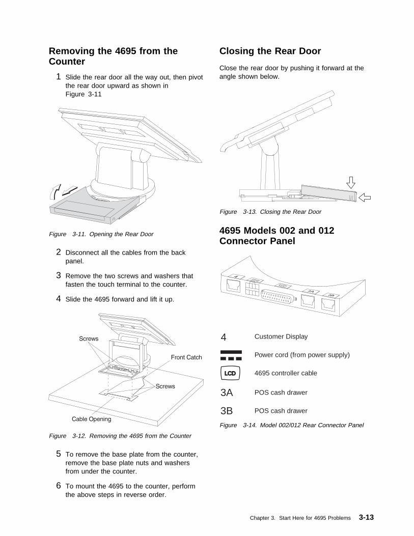
Removing the 4695 from theCounter
1 Slide the rear door all the way out, then pivotthe rear door upward as shown inFigure 3-11
Figure 3-11. Opening the Rear Door
2 Disconnect all the cables from the backpanel.
3 Remove the two screws and washers thatfasten the touch terminal to the counter.
4 Slide the 4695 forward and lift it up.
Figure 3-12. Removing the 4695 from the Counter
5 To remove the base plate from the counter,remove the base plate nuts and washersfrom under the counter.
6 To mount the 4695 to the counter, performthe above steps in reverse order.
Closing the Rear Door
Close the rear door by pushing it forward at theangle shown below.
Figure 3-13. Closing the Rear Door
4695 Models 002 and 012Connector Panel
Power cord (from power supply)
4695 controller cable
Customer Display4
POS cash drawer
POS cash drawer3B
3A
LCD
Figure 3-14. Model 002/012 Rear Connector Panel
Chapter 3. Start Here for 4695 Problems 3-13

Removing and Replacing theInterface Card and Shield
1 Remove the 4695 from the counter. Seepage 3-13.
2 Remove the shield from underneath theswivel base by carefully bending the middleoutward.
3 Press the two snaps as shown inFigure 3-15 and remove the interface cardfrom underneath the touch terminal.
4 Unplug the digital interface cable from theinterface card.
Figure 3-15. Removing the Interface Card
5 To exchange the interface card, connect thedigital interface cable, and place the cardunder the tabs first, then under the snaps.
6 To install the shield and mount the 4695 tothe counter, perform the above steps inreverse order.
Removing and Replacing thePedestal Stand
1 Remove the 4695 from the counter. Seepage 3-13.
2 Remove the tablet and the clutch. See page3-12.
3 Unplug the digital interface cable from thetablet.
4 Rotate the swivel base 90 degrees clockwiseto align the plastic tab with the metal tab.
5 Remove the shield from underneath theswivel base by carefully bending the middleof the shield outward.
Figure 3-16. Releasing the Pedestal
6 Pull the tab down, away from the base, torelease the pedestal from the base.
3-14 4693, 4694, and 4695 Hardware Service Manual

7 Remove the four screws from the bottom ofthe pedestal stand.
Figure 3-17. Removing the Pedestal Stand
8 Press the two snaps as shown inFigure 3-17 and slide the pedestal stand outfrom the pedestal cover.
9 To exchange the pedestal stand or pedestalcover, perform the above steps in reverseorder.
Removing and Replacing theRear Door
1 Slide the rear door all the way out. Thenslide the rear door half-way forward to theposition shown and remove the rear door bylifting it out of the slots.
Figure 3-18. Removing the Rear Door
2 To exchange the rear door, place the reardoor down into the slot and slide it forward.
Note: If the customer display is installed,disconnect the customer display cable from theinside of the rear door.
Chapter 3. Start Here for 4695 Problems 3-15

Removing and Replacing theCustomer Display
1 Open the rear door. See Figure 3-11 onpage 3-13.
2 Unplug the customer display cable from thecustomer display connector on the 4695.
3 Release the snaps on the sides of thecustomer display from inside the rear doorand remove the customer display from the4695.
Figure 3-19. Removing the Customer Display
4 Unplug the customer display cable from thecustomer display.
5 To exchange the customer display, performthe above steps in reverse order. Route thecable with the toroid as shown.
Figure 3-20. Replacing the Customer Display
Clips
Figure 3-21. Routing the Customer Display Cable
Removing, Replacing, andCleaning the Customer DisplayLens
1 Remove the customer display from the reardoor.
2 Using a small flatblade screwdriver andstarting at the top edge of the display, pry atthe points indicated to release the lensframe.DO NOT SPRAY CLEANING SOLUTIONINTO THE DISPLAY.
3 Use a soft cloth dampened with a mildcleaning solution to clean the display glassand the lens.
4 To remove the lens from the frame forreplacement, flex the frame outward asshown by the arrows and snap the lens out.
5 Position the replacement lens into the framefrom the outside and snap it into position inthe frame.
6 Snap the frame onto the display starting atthe bottom edge.
7 Install the display into the rear door.
3-16 4693, 4694, and 4695 Hardware Service Manual

Lens
Figure 3-22. Removing the Frame and Lens
Removing and Replacing theMSR
1 Push a small allen wrench or paper clip intoa slot underneath the MSR as shown. Pushupward to unlatch the MSR and pull theMSR out sideways from the tablet. Repeatthis procedure for the second slot.
Note: To remove the MSR blanks, use thesame procedure.
2 To exchange the MSR, perform the abovesteps in reverse order.
Chapter 3. Start Here for 4695 Problems 3-17
Problem Determination – 4695 Models 201 and 211
This section contains the problem determination procedures for 4695 Models 201 and 211.
Preliminary Checklist
1 Observe the power indicators on the touch display and the power supply. If they are not ON, go to“Symptom Table – 4695 Models 201 and 211” on page 3-19.
2 Make sure all I/O devices are connected correctly.
3 Make sure the correct diskette is inserted.
4 Make sure all hardware devices installed (such as memory modules or feature cards) are connectedcorrectly. .
5 Switch POWER OFF then ON and listen for beeps at the completion of POST. A single beepindicates a successful completion. No beeps or more than one indicates a failure. If a failure isindicated, see “Symptom Table – 4695 Models 201 and 211” on page 3-19.
6 When using application programs, you may receive error messages that pertain to the applicationsoftware. See the application program manual for a description of those messages.
Note:
� If your system passes these preliminary checks and the problem still exists, record any error codes.See “Models 201 and 211” on page 3-21 for a list of error codes and messages.
� If your system fails and there is no error code, see “Symptom Table – 4695 Models 201 and 211” onpage 3-19 for a list of symptoms and problem determination procedures.
3-18 4693, 4694, and 4695 Hardware Service Manual

Symptom Table – 4695 Models 201 and 211
For exchanging FRUs, see “Removals and Replacements – 4695 Models 201 and 211” on page 3-35.
Table 3-8 (Page 1 of 2). Troubleshooting Chart – Models 201 and 211
If the problem is... Here’s what to do...
The power indicators on thetouch display or power supplyare not ON
� Check that the power supply is plugged into a known good AC outlet andreseat the power cable into the 4695.
� Check for blown fuses, a tripped circuit breaker, or a power failure.� Test the 4695 power supply:
– Switch POWER OFF at the 4695.– Disconnect the power cord from the rear of the 4695.– Plug the 4695 wrap plug (P/N 13H6231) into the end of the power cable
you disconnected from the power supply.– If the power indicator on the power supply is OFF, exchange the power
supply.– If the power indicator on the power supply is ON, measure the voltages
at the wrap plug. If the voltages are not within the following ranges,exchange the power supply.Pin Range1 (Gnd) –2 (+5 V DC) 4 – 6.5 V DC3 (+12 V DC) 9 – 15 V DC4 (+38 V DC) 30 – 48 V DC5 (power good) greater than 3 V DC
� Exchange the digital interface cable. 1
� Exchange the touch screen controller card. 1
� Exchange the system board.
A beep code is sounded duringPOST (a single beep indicates asuccessful completion)
Go to “POST Beep Codes – 4695 Models 201 and 211” on page 3-26.
When the screen is touched,there is no response
� Run the touch screen test using the service diskette. If the test is successful,the software may be failing.
� Exchange the touch ring cable. 1
� Exchange the touch screen controller card. 1
� Exchange the touch ring card. 1
� Remove the front cover of the touch screen. 1 Run the touch screen testusing the service diskette. If the test is successful, exchange the front cover.
Blank touch display � Check that the power indicator on the display is ON. If not, go to the firstsymptom in this table.
� Check that the backlight is ON (the display is illuminated). If the backlight innot ON, go to the Backlight symptom in this table on page 3-20.
� Check that the display cable is securely connected. 1
� Exchange the display cable. 1
� Exchange the touch screen controller card. 1
� Exchange the display. 1
1 See “Removing and Replacing the Tablet FRUs” on page 3-36.
Chapter 3. Start Here for 4695 Problems 3-19

Table 3-8 (Page 2 of 2). Troubleshooting Chart – Models 201 and 211
If the problem is... Here’s what to do...
Incorrectly displayed data � Run the 4695 display test using the service diskette. If the test is successful,the software may be failing.
� Check that the display cable is securely connected. 1
� Exchange the display cable.� Exchange the touch screen controller card. 1
� Exchange the display. 1
Vertical bars appear across thetop or bottom half of the touchdisplay
� Check that the display cable and digital interface cable are securelyconnected. 1
� Exchange the digital interface cable. 1
� Exchange the touch screen controller card. 1
Blocks of missing data on touchdisplay
� Exchange the display. 1
Cash Drawer � Check that the cash drawer is securely connected to the 4695.� Run the cash drawer test using the service diskette.� Exchange the cash drawer cable.� Exchange the cash drawer latch assembly.� Exchange the touch screen controller card.
Fixed Disk � Run the fixed disk test using the service diskette.� Run setup and review the fixed disk configuration to ensure that it is properly
configured. See “Running Setup – 4695 Models 201 and 211” on page 3-55.� Check that the fixed disk is securely connected to the system board.� Exchange the fixed disk cable.� Exchange the fixed disk.
Magnetic Stripe Reader (MSR) � Make sure the MSR is securely attached to the touch display.� Run the MSR test using the service diskette.� Exchange the MSR.� Exchange the touch screen controller card.
Customer Display � Make sure the customer display cable is securely connected to the customerdisplay and to the 4695.
� Run the customer display test using the service diskette.� Exchange the customer display cable.� Exchange the customer display.
Backlight:Dim, dark, or partially lit touchdisplay
� Adjust the contrast and brightness on the display using the service diskette.� Check that the backlight is good by using the test on the service diskette.� Check that the backlight is securely connected.� Exchange the backlight.
Note: Do not exchange the display to solve this problem.
Terminal not working at all Start at “Preliminary Checklist” on page 3-18.
Diskette drive � Make sure you are using the correct type of diskette and that it is formatted.� Make sure the diskette is inserted in the drive correctly.� Use a known good diskette. If it works, the first diskette might not be valid.� Boot terminals using the 4695 Service Diskette and run the diskette drive
test.� Exchange the diskette drive cable.� Exchange the diskette drive.
Cannot send information (write)to a diskette or cannot format adiskette
� Make sure the diskette is not write-protected.� Use a known good diskette.� Boot the 4695 Service Diskette and run the diskette drive test.� Exchange the diskette drive cable.� Exchange the diskette drive.
3-20 4693, 4694, and 4695 Hardware Service Manual
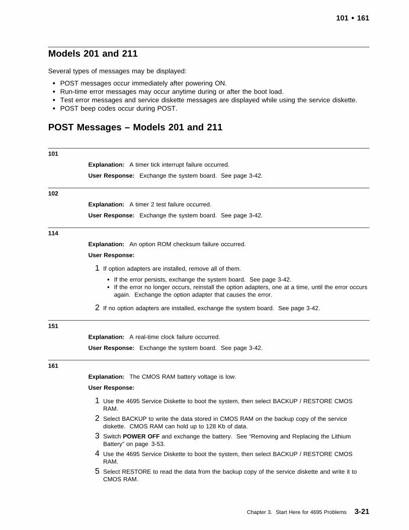
101 � 161
Models 201 and 211
Several types of messages may be displayed:
� POST messages occur immediately after powering ON.� Run-time error messages may occur anytime during or after the boot load.� Test error messages and service diskette messages are displayed while using the service diskette.� POST beep codes occur during POST.
POST Messages – Models 201 and 211
101
Explanation: A timer tick interrupt failure occurred.
User Response: Exchange the system board. See page 3-42.
102
Explanation: A timer 2 test failure occurred.
User Response: Exchange the system board. See page 3-42.
114
Explanation: An option ROM checksum failure occurred.
User Response:
1 If option adapters are installed, remove all of them.
� If the error persists, exchange the system board. See page 3-42.� If the error no longer occurs, reinstall the option adapters, one at a time, until the error occurs
again. Exchange the option adapter that causes the error.
2 If no option adapters are installed, exchange the system board. See page 3-42.
151
Explanation: A real-time clock failure occurred.
User Response: Exchange the system board. See page 3-42.
161
Explanation: The CMOS RAM battery voltage is low.
User Response:
1 Use the 4695 Service Diskette to boot the system, then select BACKUP / RESTORE CMOSRAM.
2 Select BACKUP to write the data stored in CMOS RAM on the backup copy of the servicediskette. CMOS RAM can hold up to 128 Kb of data.
3 Switch POWER OFF and exchange the battery. See “Removing and Replacing the LithiumBattery” on page 3-53.
4 Use the 4695 Service Diskette to boot the system, then select BACKUP / RESTORE CMOSRAM.
5 Select RESTORE to read the data from the backup copy of the service diskette and write it toCMOS RAM.
Chapter 3. Start Here for 4695 Problems 3-21
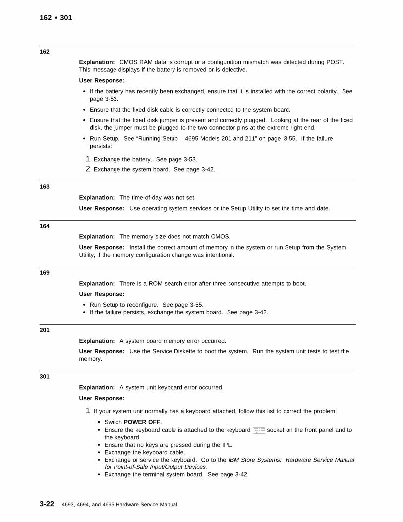
162 � 301
162
Explanation: CMOS RAM data is corrupt or a configuration mismatch was detected during POST.This message displays if the battery is removed or is defective.
User Response:
� If the battery has recently been exchanged, ensure that it is installed with the correct polarity. Seepage 3-53.
� Ensure that the fixed disk cable is correctly connected to the system board.
� Ensure that the fixed disk jumper is present and correctly plugged. Looking at the rear of the fixeddisk, the jumper must be plugged to the two connector pins at the extreme right end.
� Run Setup. See “Running Setup – 4695 Models 201 and 211” on page 3-55. If the failurepersists:
1 Exchange the battery. See page 3-53.
2 Exchange the system board. See page 3-42.
163
Explanation: The time-of-day was not set.
User Response: Use operating system services or the Setup Utility to set the time and date.
164
Explanation: The memory size does not match CMOS.
User Response: Install the correct amount of memory in the system or run Setup from the SystemUtility, if the memory configuration change was intentional.
169
Explanation: There is a ROM search error after three consecutive attempts to boot.
User Response:
� Run Setup to reconfigure. See page 3-55.� If the failure persists, exchange the system board. See page 3-42.
201
Explanation: A system board memory error occurred.
User Response: Use the Service Diskette to boot the system. Run the system unit tests to test thememory.
301
Explanation: A system unit keyboard error occurred.
User Response:
1 If your system unit normally has a keyboard attached, follow this list to correct the problem:
� Switch POWER OFF.� Ensure the keyboard cable is attached to the keyboard socket on the front panel and to
the keyboard.� Ensure that no keys are pressed during the IPL.� Exchange the keyboard cable.� Exchange or service the keyboard. Go to the IBM Store Systems: Hardware Service Manual
for Point-of-Sale Input/Output Devices.� Exchange the terminal system board. See page 3-42.
3-22 4693, 4694, and 4695 Hardware Service Manual

303 � 2400
2 If your system unit normally has no keyboard attached, follow this list to correct the problem.
� Temporarily connect a keyboard to the system unit and invoke the ROM-based Setup UtilityProgram or go to another system unit that has a keyboard and run the setup diskette. See“Running Setup – 4695 Models 201 and 211” on page 3-55.
� Select the Boot Options Setup Menu.� Enable keyboardless operation.� Save these settings.
� Exit Setup.� If you connected a keyboard to the failing system unit, disconnect it.� If you created a setup diskette on a different system, boot it in the failing system. The
configuration record is automatically corrected.
303
Explanation: A terminal system unit keyboard error occurred.
User Response: Exchange the terminal system board. See page 3-42.
306
Explanation: A keyboard password is in effect and the keyboard is locked.
User Response: Ignore this message if the keyboard is not used. Otherwise, type the keyboardpassword when prompted.
601
Explanation: A diskette controller failure occurred.
User Response: Exchange the system board. See page 3-42.
602
Explanation: The diskette boot record was not valid.
User Response: Remove the diskette if you did not intend to boot the system from a diskette.Otherwise, exchange the diskette with one that has a valid boot record.
604
Explanation: A diskette drive failure occurred.
User Response: Exchange the diskette drive. See page 3-41.
1780
Explanation: A fixed disk configuration error or fixed disk failure occurred.
User Response: Run Setup. See page 3-55.
If running Setup does not correct the problem:
1 Exchange the fixed disk cable.
2 Exchange the fixed disk. See page 3-40.
2400
Explanation: A display adapter failure occurred while using an alternate display adapter.
User Response: Exchange the system board. See page 3-42.
Chapter 3. Start Here for 4695 Problems 3-23

6300 and 6308 � 8603
6300 and 6308
Explanation: The POS I/O configuration record is corrupted.
User Response: Use the 4695 Service Diskette to boot the system. This should correct theconfiguration record.
If the failure persists each time the service diskette is booted, exchange the system board.
8310
Explanation: A device channel failure occurred.
User Response:
1. Exchange the Point-of-Sale Adapter.2. Exchange the system board. See page 3-42.
8350
Explanation: Non-volatile RAM data is not valid.
User Response:
1. If the error occurs after specific operations are completed before powering off, the NVRAM datawas corrupted by software.
2. If the error occurs every time power remains off for a specific amount of time, the Point-of-SaleAdapter battery or the system board might be failing. Exchange the Point-of Sale Adapter.Exchange the system board. See page 3-42.
8381
User Response: Switch the system POWER OFF, unplug all POS I/O devices connected to the rearof the system unit, then switch power ON again. If the failure occurs only when POS devices areconnected to the system unit, isolate and exchange the failing device; otherwise, exchange:
� The Point-of-Sale Adapter.� The system board. See page 3-42.
8382
Explanation: The device channel port B wrap-back test failed.
User Response: Switch the system POWER OFF, unplug cable number 11 from the rear of thesystem unit, then power ON again. If the failure occurs only when cable number 11 is connected to thesystem unit, use the appropriate service documentation to repair the satellite terminal. Otherwise,exchange the system board in the 4695. See page 3-42.
8601
Explanation: A pointer device (mouse) failure occurred.
User Response: Exchange the pointer device.
8603
Explanation: A pointer device (mouse) has been removed.
User Response: Reconnect the pointer device or run Setup if the configuration change wasintentional.
3-24 4693, 4694, and 4695 Hardware Service Manual

0133nnnn � 2650006
0133nnnn
Explanation: An IBM Wireless LAN adapter error occurred.
User Response:
1 Run the IBM Wireless LAN tests.
2 Continue problem determination using the maintenance documentation provided with the IBMWireless LAN. See the “Troubleshooting Wireless Network Problems” appendix in the IBMWireless LAN: Installing and Operating Your Network
2650001
Explanation: Ethernet POST ROM integrity error.
User Response:
� Reboot the system unit.� Exchange the memory simms one at a time.� Exchange the system board. See page 3-42.
2650002
Explanation: Ethernet shared memory interface error.
User Response:
� Exchange the memory simms one at a time.� Exchange the system board. See page 3-42.
2650003
Explanation: Ethernet IRQ Setup error.
User Response:
� Run Setup. Choose an IRQ that is not being used for other system hardware.� Exchange the system board. See page 3-42.
2650004
Explanation: Ethernet interrupt failure.
User Response:
� Run Setup. Choose an IRQ that is not being used for other system hardware.� Exchange the system board. See page 3-42.
2650005
Explanation: Ethernet EEPROM integrity error.
User Response: Exchange the system board. See page 3-42.
2650006
Explanation: Ethernet buffer memory integrity error.
User Response:
� Exchange the memory simms one at a time.� Exchange the system board. See page 3-42.
Chapter 3. Start Here for 4695 Problems 3-25

2650008 � I9990305
2650008
Explanation: Ethernet transmission loopback error.
User Response: Exchange the system board. See page 3-42.
2650009
Explanation: Ethernet host bus interface error.
User Response: Exchange the system board. See page 3-42.
2650010
Explanation: Ethernet adapter not available for RPL.
User Response: Exchange the system board. See page 3-42.
I9990301
Explanation: No boot device was found. The diskette drive and the LAN adapter are failing. Thefixed disk is also failing, if one is present.
User Response:
1. Exchange the diskette drive. See page 3-41.2. Exchange the fixed disk. See page 3-40.3. Exchange the system board. See page 3-42.
I9990303
Explanation: A boot drive failure occurred.
User Response:
1. Exchange the diskette drive if the system is trying to boot from a diskette. See page 3-41.2. Exchange the fixed disk if the system is trying to boot from the fixed disk. See page 3-40.
I9990305
Explanation: No bootable media was found.
User Response: Insert a bootable diskette, install a boot record on the fixed disk, or connect thesystem unit to a LAN that is configured to boot the 4695 Model 201 or Model 211.
POST Beep Codes – 4695 Models 201 and 211
Beep codes are sequences of tones that present hardware failures to the speaker. For example, beepcode 2-1-4 (a burst of two beeps, a single beep, and a burst of four beeps) indicates a system boardfailure. Beep codes are required anytime a failure is detected prior to initialization of the video subsystem.
Table 3-9 (Page 1 of 2). Beep Codes
Beep Code Description Corrective Action
Two beeps following POST An error was detected duringPOST.
Look for any displayed error messages. See“POST Messages – Models 201 and 211” onpage 3-21.
1-1-4 A system board test errorwas detected during POST.
� If a FLASH update was attempted just priorto this beep code, see “4695 Service LevelUpdate Procedure” on page 3-4 and performthis procedure.
� Exchange the system board. See page3-42.
3-26 4693, 4694, and 4695 Hardware Service Manual

Run-time Error Messages – 4695 Models 201 and 211
These messages are called run-time errors because they typically occur during or after the boot load.When these errors occur, the BIOS displays, in segment:offset format, the address of the failing softwareinstruction. See xxxx:xxxx in the Message column of Table 3-10. In cases of memory parity errors, thesoftware instruction address can be, but is not always the location of the parity error. When anunexpected interrupt occurs, BIOS displays the failing interrupt number. (See nn in the Message columnof 3-27.)
Table 3-9 (Page 2 of 2). Beep Codes
Beep Code Description Corrective Action
1-1-2 1-1-3 1-2-11-2-2 1-2-3 1-2-42-1-1 2-1-2 2-1-32-1-4 2-2-1 2-2-22-2-3 2-2-4 2-3-12-3-2 2-3-3 2-3-42-4-1 3-1-1 3-1-23-1-4 3-2-1 3-2-2
3-2-3
A system board test errorwas detected during POST.
� Ensure that the fixed disk cable is correctlyattached to the system board.
� Exchange the system board. See page3-42.
1-3-1 1-3-2 3-1-3
A memory test error wasdetected during POST.
� Exchange the memory modules. See page3-40.
� Exchange the system board. See page3-42.
One long beep followed by upto six short beeps
A video subsystem error wasdetected during POST.
Exchange the system board. See page 3-42.
3-2-4 3-3-1
A memory size mismatchwas detected during POST.
� Run setup to reconfigure CMOS. See page3-55.
� Exchange the memory module(s). See page3-40.
� Exchange the system board. See page3-42.
Table 3-10. Run-time Error Messages
Message Description Corrective Action
I/O card parity interrupt atxxxx:xxxx . Type (S)hut off NMI,(R)eboot, other keys to continue.
Memory on an option adapter hasfailed.
Check the memory on the optionadapters.
Memory parity interrupt atxxxx:xxxx . Type (S)hut off NMI,(R)eboot, other keys to continue.
A memory SIMM on the systemboard has failed.
Check the memory on the systemboard.
Unexpected type 02 interrupt atxxxx:xxxx . Type (S)hut off NMI,(R)eboot, other keys to continue.
An NMI interrupt occurred, but thesource cannot be determined.
Switch system POWER OFF andON.
Unexpected HW interrupt nn atxxxx:xxxx . Type (R)eboot, otherkeys to continue.
A hardware problem occurred. Check all hardware in the system,especially option adapters.
Unexpected SW interrupt nn atxxxx:xxxx . Type (R)eboot, otherkeys to continue.
A software problem occurred. Switch POWER OFF. If the failureoccurs again, check the applicationprograms you are running in thesystem.
Chapter 3. Start Here for 4695 Problems 3-27

Test Error Messages – 4695 Models 201 and 211
603 Diskette size error
Explanation: A diskette drive test error occurred.
User Response:
1 Ensure that the diskette is either a 1 MB or 2 MB diskette.
2 Ensure that the diskette is correctly formatted.
3 Use a known good diskette.
606 Diskette verify failed
Explanation: A diskette drive test error occurred.
User Response:
1 Use a known good diskette.
2 Exchange the diskette drive cable. See page 3-41.
3 Exchange the diskette drive. See page 3-41.
4 Exchange the system board. See page 3-42.
607 Write-protect failure
Explanation: A diskette drive test error occurred.
User Response:
1 Exchange the diskette drive cable. See page 3-41.
2 Exchange the diskette drive. See page 3-41.
3 Exchange the system board. See page 3-42.
626 Data compare error
Explanation: A diskette drive test error occurred.
User Response:
1 Use a known good diskette.
2 Exchange the diskette drive cable. See page 3-41.
3 Exchange the diskette drive. See page 3-41.
4 Exchange the system board. See page 3-42.
627 Diskette change error
Explanation: A diskette drive test error occurred.
User Response:
1 Exchange the diskette drive cable. See page 3-41.
2 Exchange the diskette drive. See page 3-41.
3 Exchange the system board. See page 3-42.
3-28 4693, 4694, and 4695 Hardware Service Manual

631 Error – cause undetermined
Explanation: A diskette drive test error occurred.
User Response:
1 Exchange the diskette drive cable. See page 3-41.
2 Exchange the diskette drive. See page 3-41.
3 Exchange the system board. See page 3-42.
645 No index pulse
Explanation: A diskette drive test error occurred.
User Response:
1 Exchange the diskette drive cable. See page 3-41.
2 Exchange the diskette drive. See page 3-41.
3 Exchange the system board. See page 3-42.
648 Format test failed
Explanation: A diskette drive test error occurred.
User Response:
1 Use a known good diskette.
2 Exchange the diskette drive cable. See page 3-41.
3 Exchange the diskette drive. See page 3-41.
4 Exchange the system board. See page 3-42.
649 An incorrect media type is in the drive.
Explanation: A diskette drive test error occurred.
User Response:
1 Use a known good 1 or 2 MB diskette.
2 Exchange the diskette drive. See page 3-41.
650 No media is detected in the drive.
Explanation: A diskette drive test error occurred.
User Response:
1 Ensure that the diskette is installed correctly.
2 Exchange the diskette drive cable. See page 3-41.
3 Exchange the diskette drive. See page 3-41.
4 Exchange the system board. See page 3-42.
Chapter 3. Start Here for 4695 Problems 3-29

Address mark not found
Explanation: A diskette drive test failure occurred.
User Response:
1 Use a known good diskette.
2 Exchange the diskette drive cable. See page 3-41.
3 Exchange the diskette drive. See page 3-41.
4 Exchange the system board. See page 3-42.
Attachment failed to respond
Explanation: A diskette drive test failure occurred.
User Response:
1 Exchange the diskette drive cable. See page 3-41.
2 Exchange the diskette drive. See page 3-41.
3 Exchange the system board. See page 3-42.
CRC on diskette read operation
Explanation: A diskette drive test failure occurred.
User Response:
1 Use a known good diskette.
2 Exchange the diskette drive cable. See page 3-41.
3 Exchange the diskette drive. See page 3-41.
4 Exchange the system board. See page 3-42.
Diskette controller has failed.
Explanation: A diskette drive test failure occurred.
User Response:
1 Exchange the diskette drive cable. See page 3-41.
2 Exchange the diskette drive. See page 3-41.
3 Exchange the system board. See page 3-42.
Media removed
Explanation: A diskette drive test failure occurred.
User Response:
1 Install a known good diskette.
2 Exchange the diskette drive cable. See page 3-41.
3 Exchange the diskette drive. See page 3-41.
4 Exchange the system board. See page 3-42.
Media type not found.
Explanation: Diskette drive test failure.
User Response: The diskette is formatted incorrectly.
3-30 4693, 4694, and 4695 Hardware Service Manual

Media type not supported
Explanation: A diskette drive test failure occurred.
User Response:
1 The diskette formatted incorrectly.
2 Exchange the diskette drive cable. See page 3-41.
3 Exchange the diskette drive. See page 3-41.
4 Exchange the system board. See page 3-42.
No media installed in the drive
Explanation: A diskette drive test failure occurred.
User Response:
1 Exchange the diskette drive cable. See page 3-41.
2 Exchange the diskette drive. See page 3-41.
3 Exchange the system board. See page 3-42.
Requested sector not found
Explanation: A diskette drive test failure occurred.
User Response:
1 Use a known good diskette.
2 Exchange the diskette drive cable. See page 3-41.
3 Exchange the diskette drive. See page 3-41.
4 Exchange the system board. See page 3-42.
Seek and diskette controller failed
Explanation: A diskette drive test failure occurred.
User Response:
1 Use a known good diskette.
2 Exchange the diskette drive cable. See page 3-41.
3 Exchange the diskette drive. See page 3-41.
4 Exchange the system board. See page 3-42.
Seek operation failed
Explanation: A diskette drive test failure occurred.
User Response:
1 Use a known good diskette.
2 Exchange the diskette drive cable. See page 3-41.
3 Exchange the diskette drive. See page 3-41.
4 Exchange the system board. See page 3-42.
Chapter 3. Start Here for 4695 Problems 3-31

Write attempted on protected diskette
Explanation: A diskette drive test failure occurred.
User Response:
1 The diskette write-protect tab is in the protect-position. Move it to the write-position and try thistest again.
2 Exchange the diskette drive cable. See page 3-41.
3 Exchange the diskette drive. See page 3-41.
4 Exchange the system board. See page 3-42.
1701 through 1718
Explanation: Fixed disk test error messages.
User Response:
Note: Message 1713 is a status message only, no action is required.
1 Exchange the fixed disk cable. See page 3-40.
Note: The user may want to try to backup the fixed disk before exchanging it. Otherwise, userdata may be lost.
2 Exchange the fixed disk. See page 3-40.
5601 and 5603
Explanation: Pointing device (mouse) test error messages.
User Response: If the failure persists, exchange the pointing device.
Service Diskette Messages – Models 201 and 211
M0002 The system board is failing.
Explanation: A system board failure was detected while running the service diskette.
User Response: Exchange the system board. See page 3-42.
M2000 A driver command failed for PORT/POLL address (xxxx) ON TERMINAL x
Explanation: xxxx is the port/poll address of the device associated with this error.
1 The service diskette may be defective. Try another service diskette.
2 The device associated with the port/poll address is failing.
3 There are incompatible features installed (two devices answering to the same Device Channeladdress).
User Response:
� Exchange the device.� If the problem persists, use a new service diskette.
3-32 4693, 4694, and 4695 Hardware Service Manual

M0320 Primary keyboard is failing.
Explanation: There is no keyboard on this terminal suitable for use as a console keyboard.
User Response: If M0320 remains in the display, ensure that the keyboard cable is connected to thekeyboard and to the 4695 system.
If the cable, sockets, and connections are OK, switch POWER OFF and follow this list to isolate andcorrect the cause of the problem:
1 Make sure that a known good keyboard is connected to the terminal.
2 Reboot the terminal and retry the operation.
3 Exchange the keyboard cable.
4 Exchange or service the keyboard. See the IBM Store Systems: Hardware Service Manual forPoint-of-Sale Input/Output Devices.
5 Exchange the system board. See page 3-42.
M0330 Primary display failed.
Explanation: There is no display on this terminal suitable for use as a console display.
User Response: If M0330 remains in the display, ensure that the display cable is connected to thedisplay and to the 4695.
If the cable, sockets, and connections are OK, switch POWER OFF and follow this list to isolate andcorrect the cause of the problem.
1 Reboot the terminal and retry the operation.
2 Exchange the display cable.
3 Exchange the display.
4 Exchange the system board. See page 3-42.
Chapter 3. Start Here for 4695 Problems 3-33

Rear Connector Panel – 4695 Models 201 and 211
3B
3A
11
12
Ethernet
A
B 4
Ethernet
B
External serial device (COM1)
External serial device (COM2)
Parallel port
Power plug (from power supply)
POS cash drawer
POS cash drawer
Ethernet cable
POS customer display
Serial I/O (SIO) satelite
VGA video (CRT)
PCMCIA card slot 1 (optional feature)
PCMCIA card slot 2 (optional feature)3B
4
11
1
2
A
3A
Front Panel – 4695 Models 201 and 211
Keylock Diskette DriveIndicator
1.44MB Diskette Drive
Keyboard cable connector
Mouse cable connector
Manager's mode
Diskette drive is unlocked
Diskette drive is locked
Ethernet link OK
Ethernet data activity
Fixed disk drive indicator
Power button
Notes:
1. The manager’s mode position unlocks the diskette drive, touch screen, and system unit cover to allowyou to remove the touch screen and system unit cover. You cannot remove the key.
2. When the diskette drive is unlocked, The touch screen and system unit cover remains locked,preventing removal. You can remove the key.
3. When the diskette drive is locked, diskettes cannot be inserted or removed. The touch screen andsystem unit cover also remain locked, preventing removal. You can remove the key.
3-34 4693, 4694, and 4695 Hardware Service Manual

Removals and Replacements – 4695 Models 201 and 211Note: Switch POWER OFF and disconnect the power cord from the electrical outlet before performingany of the removal and replacement procedures.
Removing and Replacing the Tablet1 Turn the key to the manager’s mode position
(fully counterclockwise).
2 Insert a small flat-blade screwdriver into theopening near the diskette drive as shown inFigure 3-23. Push the screwdriver inward torelease the bottom edge of the tablet fromthe wedge. Slide the tablet upward toremove it.
Attention Do not insert the screwdriver intothe diskette drive.
3 Disconnect the digital interface cable fromthe rear of the touch screen controller card.
4 To exchange the tablet, make sure that thetablet latches are in the position shown inFigure 3-24.
5 Connect the digital interface cable to the rearof the tablet.
Figure 3-23. Removing the Tablet
6 Align the tabs and insert them into theopenings in the rear tablet cover.
7 Press inward at the bottom of the tablet tolatch it into position.
Figure 3-24. Replacing the Tablet
Chapter 3. Start Here for 4695 Problems 3-35

Removing and Replacing theMSR or MSR Blanks
1 Insert a small allen wrench or paper clip intoone of the two slots underneath the MSR orblanks as shown in Figure 3-25. Push theclip upward to unlatch the snaps on the MSRor MSR blank and pull out sideways from thetablet. Repeat this procedure for the secondslot.
2 To exchange the MSR or MSR blanks, alignit to the tablet, and push inward until it snapsinto position.
Figure 3-25. Removing the MSR or MSR Blanks
Removing and Replacing theTablet FRUs
Note: It is not necessary to remove the tabletfrom the wedge to remove or exchange the FRUsinside the tablet. If you want to remove the tabletfrom the wedge, see Figure 3-23 on page 3-35.Otherwise, continue at the next step.
1 Remove the tablet cover by inserting a smallflat-blade screwdriver into the slots at the toprear of the cover and prying the cover loose.
Figure 3-26. Removing the Tablet Cover
3-36 4693, 4694, and 4695 Hardware Service Manual

Figure 3-27. Removing the Tablet FRUs
2 Disconnect the touch ring cable from thetouch ring card. See Figure 3-27.
3 Remove the touch ring card.
Attention Do not touch the LCD surface. Ifnecessary, clean the surface using isopropylalcohol and a soft cloth.
4 Unplug the backlight cable and LCD cablefrom the LCD.
5 Carefully remove the LCD.
6 If you have a color LCD, remove the groundstrap. See Figure 3-28.
7 If you have a 9.5 in. color LCD, continue atstep 10 on page 3-38. To remove thebacklight from a monochrome LCD, removethe three screws from the backlight cover. Ifyou have a 10.4 in. color LCD, see “Removing and Replacing the 4695 LCDBacklight (10.4 in.)” on page 3-38.
Figure 3-28. Removing the Ground Strap
8 Lift the backlight and backlight cable out ofthe LCD.
9 Install the new backlight with the cablerouted as shown in Figure 3-29. Continueat step 13 on page 3-38.
Figure 3-29. Removing the Monochrome Backlight
Chapter 3. Start Here for 4695 Problems 3-37

10 To remove the backlight from the colordisplay, remove the two screws from thebacklight cover.
11 Lift the backlight and backlight cable out ofthe display.
12 Install the new backlight with the cablerouted underneath the tabs as shown inFigure 3-30.
13 If you have an MSR installed, remove theMSR. See “Removing and Replacing theMSR” on page 3-17.
14 To remove the touch screen controller card,disconnect the remaining digital interfacecable from the card and unlatch the snap atthe left side of the card. When exchangingthe card, position it using the locating pinsand holes.
15 To exchange the tablet FRUs, reverse thisprocedure.
Note: When replacing the tablet cover,align the bottom edge first and then snap ittogether at the top edge.
Figure 3-30. Removing the Color Backlight
Removing and Replacing the4695 LCD Backlight (10.4 in.)
1 Switch POWER OFF and disconnect thepower cord from the electrical outlet beforeperforming any of the removal andreplacement procedures.
2 Free the backlight wires from the retainertabs. See Figure 3-31.
3 Pull the backlight latch outward and, usingyour fingernail or a small screwdriver, lift thebacklight assembly up and out of the cavityin the display.
4 Reverse this procedure to exchange thebacklight, making sure that the wires areproperly routed between the retainer tabs.
Push latchhere
Figure 3-31. Removing 10.4 inch Color Backlight.
3-38 4693, 4694, and 4695 Hardware Service Manual

Removing and Replacing the TopCover
Attention Establish personal grounding beforetouching this unit. See “Electrostatic Discharge(ESD)” on page x.
1 Turn the key to the manager’s mode position(fully counterclockwise) to unlock the cover.
Note: If no keylock is installed, the blanklock insert must be removed and the lockassembly must be rotated to the manager’smode position (fully counterclockwise) usingthe aligner tool. See “Removing andReplacing a Blank Lock Insert” onpage 3-50.
2 Open the rear cover and press the latchesinward as shown in Figure 3-32 todisengage the cover.
3 Slide the cover in the direction shown(toward the front) until it stops.
Attention There is a digital interface cablefrom the display to the system board. Whenlifting the cover to remove it, be careful notto put too much strain on the cable.
Figure 3-32. Removing the Top Cover
4 Lift the cover up and tilt to the side (facingthe front) far enough to reach in anddisconnect the digital interface cable fromthe system board. To disconnect the digitalinterface cable, press in on both sides andpull up.
5 To install the cover, connect the digitalinterface cable to the system board.Position the cover so that it fits over theridges on the base as shown in Figure 3-33.Lower the cover onto the base and slide it tothe rear until the latch engages the rearconnector panel.
Ridges
Figure 3-33. Installing the Cover
Chapter 3. Start Here for 4695 Problems 3-39

Removing and Replacing MemoryModulesNote: There are two memory module sockets on4695 Models 201 and 211 system boards. Youcan install combinations of memory modules from2 MB up to 64 MB. If you have only one moduleto install, it can be plugged into either socket. Ifyou have two modules to install, plug any sizemodule into either socket.
1 Remove the top cover. See page 3-39.
2 To remove the memory modules, release theretainers and tilt the module inward and lift itout of the socket.
3 When exchanging a memory module, insertit in into the socket as shown in Figure 3-34and rotate it upright until it latches into place.
4 Reinstall the top cover.
Retainer
Figure 3-34. Installing a Memory Module
Removing and Replacing theFixed Disk
1 Remove the top cover. See page 3-39.
2 Disconnect the fixed disk cable from thesystem board.
3 Pull outward on the metal retainer to releaseit from the tabs and lift up as shown inFigure 3-35.
Note: If the fixed disk is fastened to thebracket with four screws, remove the screws.
4 Remove the fixed disk from the bracket.
5 Disconnect the cable from the rear of thefixed disk.
6 Connect the cable to the new fixed disk andverify that the address jumper is in place.
Note: Looking at the rear of the fixed disk,the jumper must be plugged to the twoconnector pins at the extreme right end.
7 Perform the above steps in reverse order toinstall a new fixed disk.
Figure 3-35. Removing the Fixed Disk
3-40 4693, 4694, and 4695 Hardware Service Manual

Removing and Replacing theDiskette Drive
1 Remove the top cover. See page 3-39.
2 Disconnect the fixed disk cable from thesystem board.
3 Unclamp the diskette drive cable anddisconnect it from the system board.
Note: The diskette drive cable connectordoes not unplug from the system board.See Figure 3-36.
4 Remove the four screws that fasten the diskdrive bracket to the system board and lift thedrive and bracket out.
5 Remove the four screws that fasten thediskette drive to the bracket and remove thedrive.
6 Unclamp and remove the diskette drivecable from the drive.
7 To install a new diskette drive, perform theabove steps in reverse order.
Figure 3-36. Removing the Diskette Drive Cable
Removing and Replacing theFront Panel
1 Remove the top cover. See page 3-39.
2 Disconnect the keyboard and pointing devicecables (if attached).
3 Remove the two screws that fasten the frontpanel to the base.
4 Remove the four screws holding the diskettedrive bracket to the system board.
5 Remove the front panel by lifting up thediskette drive bracket and sliding the panelto the front.
Note: If you are exchanging the front panel,you must remove the lock assembly and thedoor and install them on the new panel. See“Removing and Replacing the LockAssembly FRUs” on page 3-48 and“Removing and Replacing the Front Door” onpage 3-52.
6 To exchange the front panel, perform theabove steps in reverse order.
Figure 3-37. Removing the Front Panel
Chapter 3. Start Here for 4695 Problems 3-41

Removing and Replacing theSystem Board
1 Remove the top cover. See page 3-39.
2 Remove the four screws holding the diskettedrive and the fixed disk drive bracket to thesystem board.
3 Disconnect the diskette drive and the fixeddisk drive cables from the system board.See page 3-40.
4 Remove the front panel. See page 3-41.
5 Remove the following parts from the oldsystem board, if installed on system boardswith serial numbers beginning with 41-Dxxxxand above or 77-S2xxx and above. SeeFigure 3-38 for serial number location.
� Processor, see Removing and Replacingthe Processor.
� Memory modules, see page 3-40.� Expansion Adapter, see page 3-44.� Video RAM, see page 3-43.
6 Lift the system board up and out of thesystem unit.
7 Install the parts, if any, from the old systemboard onto the new system board.
Notes:
a. Make sure the processor type jumperson the new board are in the samelocations as the jumpers on the oldboard.
b. Leave the password and the servicelevel update jumpers in the defaultpositions. See Figure 3-43 onpage 3-45 and Table 3-11 onpage 3-46.
8 Reassemble.
9 Run setup to configure the CMOS RAM.See “Running Setup – 4695 Models 201 and211” on page 3-55.
Removing and Replacing theProcessor
1 Remove the top cover. See page 3-39.
2 Place the front of the system unit facing you.
3 Slightly push the locking lever towards theleft side and then lift upward. SeeFigure 3-38.
4 Remove the old processor.
5 Locate pin 1 on the new processor. Look forone of the following markings that indicatesthe pin 1 location:
� A beveled corner of the processorcasing.
� A dot located in a corner on the top ofthe processor casing.
� A square solder joint (instead of round)at the base of a pin (bottom view).
6 Install the new processor with pin 1 locatedin the lower left corner.
7 Make sure the processor jumpers are in thecorrect locations for the new processor. SeeTable 3-11 on page 3-46 for the locationson the processor jumpers.
8 Reassemble.
P1
Serial Number
Locking Lever
Figure 3-38. Processor Locking Lever
3-42 4693, 4694, and 4695 Hardware Service Manual

Removing and Replacing theVideo RAMNote: Removal and replacement procedures are
also included in the video RAM package.
1 Remove the top cover. See page 3-39.
2 Place the front of the system unit facing you.
3 If an expansion adapter is installed, removeit now. See “Installing the ExpansionFeature” on page 3-44.
4 Insert one side of the extraction tool (partnumber 25F9651) into the extraction cavitylocated at one end of the chip carrier socket.See Figure 3-39 and Figure 3-40.
Note: Insertion of the extraction tool with anincorrect angle results in damage tothe chip carrier socket.
5 With a slight downward pressure, rotate thetool away from the chip carrier and pry thecorner of the chip away from the chip carriersocket.
6 Repeat steps 4 and 5 on the oppositeextraction slot and lift chip out of the chipcarrier socket.
7 Reassemble.
Video RAMSocket
Figure 3-39. Video RAM Socket Location
Chip CarrierSocket
Figure 3-40. Video RAM Tool
Chapter 3. Start Here for 4695 Problems 3-43

Installing the Expansion Feature
1 Remove the top cover. See page 3-39.
2 Plug the standoff into the feature card. SeeFigure 3-41.
3 Place the end of the feature card into therear panel.
4 Align the connector with the socket on thesystem board. Push down on the featurecard to ensure the connector is securelyattached to the system board.
5 Align the standoff with the hole in the systemboard and push down to snap it into place.
6 Loosen the diskette drive bracket screw andinsert the ground wire between the screwand the bracket. Tighten the screw.
Note: A ground wire is not present on the4695 Point-of-Sale Adapter.
7 Install the expansion feature controller cable.See Figure 3-42.
Expansion Feature
Expansion Socket
Standoff
Figure 3-41. Installing the Expansion Feature
N0M-018
Figure 3-42. Installing the Controller Cable
3-44 4693, 4694, and 4695 Hardware Service Manual

Jumper Information
Figure 3-43 shows the system board jumper locations. See Table 3-11 and Table 3-12 on page 3-46 forjumper descriptions.
Note: The blowout in Figure 3-43 showing JP10 and JP11 is for Cyrix processors only.
JP7JP8
JP10JP11
JP12
JP3JP5JP6
JP13JP1
PSWORD
JP4
P10
12
3
+-
Figure 3-43. System Board Jumper Locations
Chapter 3. Start Here for 4695 Problems 3-45
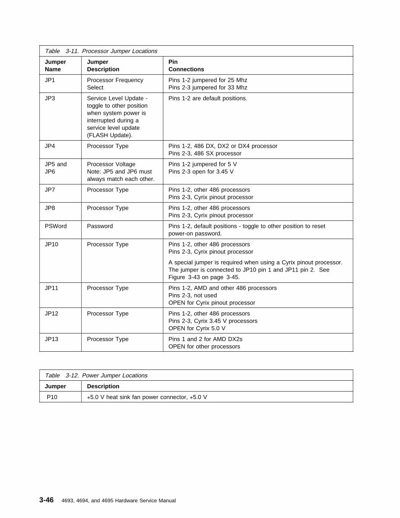
Table 3-11. Processor Jumper Locations
JumperName
JumperDescription
PinConnections
JP1 Processor FrequencySelect
Pins 1-2 jumpered for 25 MhzPins 2-3 jumpered for 33 Mhz
JP3 Service Level Update -toggle to other positionwhen system power isinterrupted during aservice level update(FLASH Update).
Pins 1-2 are default positions.
JP4 Processor Type Pins 1-2, 486 DX, DX2 or DX4 processorPins 2-3, 486 SX processor
JP5 andJP6
Processor VoltageNote: JP5 and JP6 mustalways match each other.
Pins 1-2 jumpered for 5 VPins 2-3 open for 3.45 V
JP7 Processor Type Pins 1-2, other 486 processorsPins 2-3, Cyrix pinout processor
JP8 Processor Type Pins 1-2, other 486 processorsPins 2-3, Cyrix pinout processor
PSWord Password Pins 1-2, default positions - toggle to other position to resetpower-on password.
JP10 Processor Type Pins 1-2, other 486 processorsPins 2-3, Cyrix pinout processor
A special jumper is required when using a Cyrix pinout processor.The jumper is connected to JP10 pin 1 and JP11 pin 2. SeeFigure 3-43 on page 3-45.
JP11 Processor Type Pins 1-2, AMD and other 486 processorsPins 2-3, not usedOPEN for Cyrix pinout processor
JP12 Processor Type Pins 1-2, other 486 processorsPins 2-3, Cyrix 3.45 V processorsOPEN for Cyrix 5.0 V
JP13 Processor Type Pins 1 and 2 for AMD DX2sOPEN for other processors
Table 3-12. Power Jumper Locations
Jumper Description
P10 +5.0 V heat sink fan power connector, +5.0 V
3-46 4693, 4694, and 4695 Hardware Service Manual

Removing and Replacing thePower Button
1 Remove the top cover. See page 3-39.
2 Remove the front panel. See page 3-41.
3 Lift the clip upward from the power button.
4 Pull the power button off of the switch shaft.
5 To install the power button, perform thesesteps in reverse order.
Figure 3-44. Removing the Power Button Clip
Chapter 3. Start Here for 4695 Problems 3-47

Removing and Replacing theLock Assembly FRUs
1 Remove the top cover. See page 3-39.
2 Remove the front door. See page 3-52.
3 Remove the front panel. See page 3-41.
4 Position the keylock in the unlocked position(center position).
5 Lift and remove the clip to release the flagassembly.
6 Slide the flag assembly and spacer off thekeylock barrel. The lock gear falls out of theflag assembly as it is pulled off the shaft.
7 Remove the keylock from the front panel.
8 To exchange the lock assembly FRUs, placethe keylock in the unlocked position (centerposition) and insert it into the front panel.
9 Slide the flag assembly and spacer onto thekeylock and place the lock gear on the endof the keylock shaft.
10 Place the keylock in the locked position (fullyclockwise).
11 Position the flag assembly and lock gear asshown in Figure 3-45.
12 Rotate the keylock counterclockwise enoughto fasten the flag assembly into place withthe clip.
Note: The clip goes between the lockspacer and the flag assembly.
13 Reinstall the front panel, front cover, and thetop cover. Figure 3-45. Lock Assembly
3-48 4693, 4694, and 4695 Hardware Service Manual

Removing and Replacing a LockInsert
1 To remove the lock insert, place the brassinstallation/removal key fully into the lock.
2 Gently pull the brass key.
The brass key and the lock insert comes outof the lock cylinder together. Pressingdownward or sideways on the brass key asyou pull makes it easier for the lock insert tocome out along with the brass key.
3 To exchange the lock insert, place thealigner into the empty lock cylinder andgently turn the aligner until you feel it go intothe slot at the bottom of the lock cylinder.
4 Turn the aligner so that the arrow points inthe direction shown.
Aligner
5 Remove the aligner.
6 Remove the keys that came with the lockinsert.
7 Place the brass installation/removal key fullyinto the lock insert.
8 Hold the lock and brass key so that the keypoints in the same direction as did thealigner.
9 Push the lock insert and brass key fully intothe empty lock cylinder.
Lock Insert
10 Hold the lock insert in place with your fingerand remove the brass key.
11 Test the lock to be sure it operates correctlywith the keys.
Chapter 3. Start Here for 4695 Problems 3-49

Removing and Replacing a BlankLock Insert
Blank lock inserts are used to cover the openingat the lock cylinder if no lock has been installed.
1 To remove the blank lock insert, use theblank lock allen wrench to turn the lockingscrew counterclockwise until the insert canbe removed. The blank lock inserts have alug on one end that must be aligned.
2 To exchange the blank lock insert, positionthe blank lock insert so that the lug isaligned with the slot in the lock cylinder.
3 Install the blank lock insert into the emptylock cylinder until it is flush with the top ofthe lock cylinder.
Blank Lock Insert
4 Use the blank lock allen wrench to turn thelocking screw clockwise until it reaches thebottom of the hole. Do not overtighten.
Wrench
Removing and Replacing theUpper Wedge
1 Remove the tablet. See Figure 3-23 onpage 3-35.
2 Remove the top cover. See page 3-39.
3 Pivot the wedge to the uppermost position.
4 Pry the two tabs on the upper wedge inwardto release them from the lower wedge. Thismay be easiest to do from underneath thelower wedge.
5 Using grease part number 93F0415,lubricate the grooves inside the new upperwedge.
6 Position the upper wedge so that thegrooves align with the ends of the gear shaftin the lower wedge.
7 Press the tabs at the front of the upperwedge into the grooves at the front of thelower wedge until they snap into place.Ensure that the upper wedge tilts up anddown without binding.
Figure 3-46. Removing and Replacing the UpperWedge
3-50 4693, 4694, and 4695 Hardware Service Manual

Removing and Replacing theTablet Latch
1 Remove the top cover. See page 3-39.
2 Remove the upper wedge from the lowerwedge. See page 3-50.
3 Press the tab on the upper wedge as shownin Figure 3-47.
4 Turn the upper wedge upside down, pressthe two tabs, and remove the tablet latch inthe direction shown in Figure 3-48.
5 Press the latch spring on both sides andremove it.
6 To exchange the tablet latch, press the twotabs and slide the tablet latch down into thecover as shown in Figure 3-48.
Figure 3-47. Removing the Tablet Latch - Part 1
Removing and Replacing theLower Wedge Shaft Assembly
1 Remove the upper wedge. See page 3-50.
2 Pull the two gears off the shaft in the lowerwedge.
3 Unclip the spring from the lower wedge.
4 Slide the shaft to the right until you canremove it from inside the wedge.
5 To exchange the shaft assembly, lubricatethe ends of the shaft with grease partnumber 93F0415. Perform the above stepsin reverse order.
Note: When installing or exchanging thegears, the orientation of the gears isimportant. The orientation marks on each ofthe two gears must be facing to the rightside. See “Removing and Replacing theUpper Wedge” on page 3-50.
Figure 3-48. Removing the Tablet Latch - Part 2
Chapter 3. Start Here for 4695 Problems 3-51

Removing and Replacing theFront Door
1 With your fingers at both sides of the frontdoor, swing the door out and downward untilit unsnaps.
2 To exchange the front door, snap the dooronto the front panel.
Removing and Replacing theRear Door
1 Remove the top cover. See 3-39.
2 If a customer display is attached, disconnectit from the rear connector panel socket 4.
3 Placing your fingers on each side of the reardoor, pull the tabs that hold the rear door tothe system unit outward, then remove therear door.
Figure 3-49. Removing the Rear Door
Removing and Replacing theCustomer Display
1 Open the rear door.
2 Unplug the customer display cable from therear connector panel socket 4.
3 Disengage the snaps on the sides of thecustomer display from inside the rear doorand remove the customer display from the4695.
4 Unplug the customer display cable from thecustomer display.
5 To exchange the customer display, performthe above steps in reverse order. SeeFigure 3-50. Ensure that the customerdisplay cable is routed as shown inFigure 3-51.
Figure 3-50. Installing the Customer Display
Figure 3-51. Routing the Customer Display Cable
3-52 4693, 4694, and 4695 Hardware Service Manual

Removing, Replacing, andCleaning the Customer DisplayLens
1 Remove the customer display from the reardoor. See page 3-52.
2 Using a small flat-blade screwdriver andstarting at the top edge of the display, pry atthe points indicated in Figure 3-52 to releasethe lens frame.
Attention Do not spray cleaning solution intothe display.
3 Use a soft cloth dampened with a mildcleaning solution to clean the display glassand the lens.
4 To remove the lens from the frame forreplacement, flex the frame outward asshown by the arrows and snap the lens out.
5 Place the replacement lens into the framefrom the outside and snap it into position inthe frame.
6 Snap the frame onto the display starting atthe bottom edge.
7 Install the customer display into the reardoor.
Lens
Figure 3-52. Removing the Frame and Lens
Removing and Replacing theLithium BatteryCAUTION:Replaceable lithium batteries: Do not open,throw in fire, recharge, or short circuit.Replace only with the same or equivalent typerecommended by the manufacturer.
1 Remove the top cover. See 3-39.
2 It is important that the new battery beinstalled with the correct polarity. Notice thepolarity markings on the battery beforeremoving the old one. See Figure 3-53 onpage 3-54.
3 Remove the lithium battery from the batteryholder.
4 To install the new lithium battery, performthe above steps in reverse order.
5 When a new battery is installed, the CMOSRAM data must be restored. This can bedone in one of three ways:
� Run RESTORE CMOS RAM from theservice diskette if BACKUP was run priorto removing the battery. See “4695Service Diskette Introduction” onpage 3-2.
� Use the setup diskette (if available).� Run the ROM-based setup program.
See “Running Setup – 4695 Models 201and 211” on page 3-55.
Chapter 3. Start Here for 4695 Problems 3-53
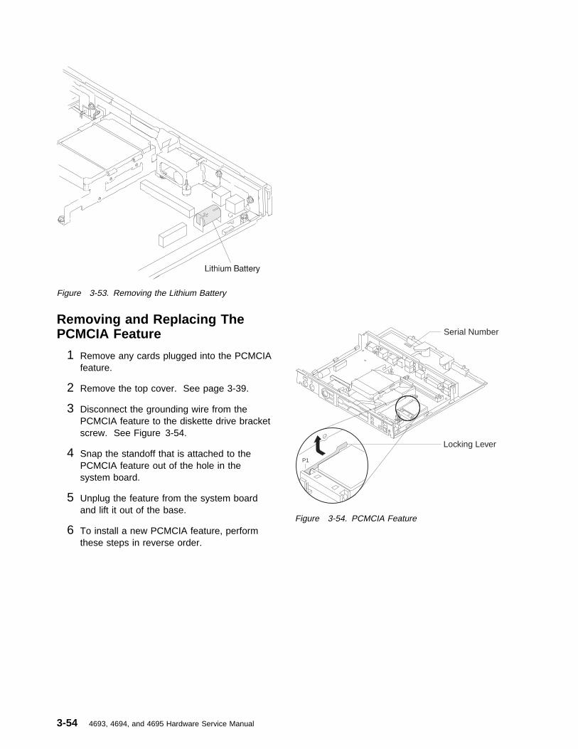
Figure 3-53. Removing the Lithium Battery
Removing and Replacing ThePCMCIA Feature
1 Remove any cards plugged into the PCMCIAfeature.
2 Remove the top cover. See page 3-39.
3 Disconnect the grounding wire from thePCMCIA feature to the diskette drive bracketscrew. See Figure 3-54.
4 Snap the standoff that is attached to thePCMCIA feature out of the hole in thesystem board.
5 Unplug the feature from the system boardand lift it out of the base.
6 To install a new PCMCIA feature, performthese steps in reverse order.
P1
Serial Number
Locking Lever
Figure 3-54. PCMCIA Feature
3-54 4693, 4694, and 4695 Hardware Service Manual

Running Setup – 4695 Models 201 and 211
The basic input/output system (BIOS) configuration of each 4695 can be customized for the hardware andfeatures installed. There is a ROM-based setup utility in each 4695 Model 201 and 211 to perform thisfunction. The setup utility is initiated by operator intervention during power-on self-test (POST).
To start the setup utility, perform the following steps:
1 Switch POWER ON at the 4695 and look for F1 to appear in the upper right-hand corner of thetouch display.
2 If a PC-type keyboard is attached, press the F1 key on the keyboard.
If no PC-type keyboard is attached, touch F1 on the display.
Note: You must press the F1 key or touch F1 on the display while it is visible on the display.
The MAIN MENU appears when POST is complete.
If the MAIN MENU does not appear, you must use a setup diskette to run the Setup utility. Go to“4695 Setup Diskette” on page 3-56.
3 The MAIN MENU is: � System Setup� Fixed Disk Setup� Device Channel Setup
� Ethernet Setup � Change Password � Boot Options � System Summary � Save Settings � Restore Settings� Load Default Settings
� Exit Setup
4 At the MAIN MENU, select LOAD DEFAULT SETTINGS.
5 Make the desired selections from each of the first five menu items. You can make changes to anyof the fields that have square brackets ([ ]) around their values. Fields without the brackets are forinformation only.
6 Select SYSTEM SUMMARY to review your selections.
7 Select SAVE SETTINGS.
8 Select EXIT SETUP. The 4695 reboots automatically using any new setup information that youentered.
Note: If you have changed the Ethernet memory address, you must POWER OFF then ON to loadthe new address.
Chapter 3. Start Here for 4695 Problems 3-55

4695 Setup Diskette
This section provides instructions on how to create a setup diskette and describes how and when to use it.
Creating A Setup Diskette
Programs and information files required to create a setup diskette are distributed on the 469xSupplemental Drivers Diskette SX27-3934-03, V2.00 or later. They can be found in the \4695\UTILsubdirectory.
The name of the program used to create the setup diskette is:
CMOSETUP.EXE
Information about using this program can be found in the following file:
CMOSETUP.DOC
The following data file contains the resulting CMOS setup data that is generated when creating a setupdiskette:
CMOSFILE
Additional program files are necessary when creating a setup diskette. The names of these program filesare:
CMOSBIOS.COM CCBOOTS.COM CCMOS.COM SETUP.COM
To create a setup diskette:
Note: A PC-type keyboard must be attached to the system unit.
1 Copy all seven of the data and program files listed above from the 469x Supplemental DriversDiskette \4695\UTIL subdirectory to the fixed disk of the computer or 4695 where the diskette is tobe created.
2 Go to the directory or subdirectory where the files were placed and type the following:
CMOSETUP /S
where /S requests 'run 4695 setup'
3 When the Main Menu appears, select LOAD DEFAULT SETTING.
4 Make the desired selections from each of the first five menu items. You can make changes to anyof the fields that have square brackets ([ ]) around their values. Fields without the brackets are forinformation only.
Notes:
a. It is not required that you choose a fixed disk type or enter the time and date. The correct fixeddisk type is configured automatically when Setup is run on the 4695. The time and date must beset by the operating system or application program.
b. Press the F1 key one time for help information or press the F1 key two times for more detailedhelp information.
3-56 4693, 4694, and 4695 Hardware Service Manual

5 When you have entered all the information select: SAVE SETUP.
The CMOSFILE is then updated with your setup data.
6 Insert a blank formatted diskette in the A drive of your computer or 4695 when instructed to do so.
7 The CMOSFILE, in addition to the necessary program files, are written to the diskette in the A drive.This is now a bootable diskette that performs setup automatically when booted in the 4695.
8 If you want to create additional bootable diskettes with the same 4695 setup data that was createdin step 5, without running setup each time, type the following without any parameters: CMOSETUP.
Using the Setup Diskette
There are two situations where a 4695 Setup Diskette may be used:
1. For 4695s where the Setup utility cannot be initiated from the PC-type keyboard or touch display, asetup diskette is required to perform Setup. This is typically done at the time of installation or after afailing system board has been exchanged. The Setup diskette is prepared at a PC or terminal thathas a PC-type keyboard attached. It is used to boot the keyboardless 4695 and setup is performedautomatically.
2. If all 4695s in a store are to be configured the same way, a setup diskette can be created at a centralsite and then distributed to the store at installation time. Rather than performing manual setup oneach 4695, you simply use the setup diskette to boot each 4695 and it is automatically configured.The setup diskette can be used in any 4695 Model 201 or 211 whether it has a PC-type keyboard ornot.
Chapter 3. Start Here for 4695 Problems 3-57

3-58 4693, 4694, and 4695 Hardware Service Manual

Appendix A. 4693 Hardware Overview
Front and Rear Views of the IBM 4693 . . . . . . . . . . . . . . . . . . . . . . . . . . . . . . . . . . A-2Sockets and Devices . . . . . . . . . . . . . . . . . . . . . . . . . . . . . . . . . . . . . . . . . . . . . A-3Rear Connector Panels . . . . . . . . . . . . . . . . . . . . . . . . . . . . . . . . . . . . . . . . . . . . A-4Description of 4693 Power Modes . . . . . . . . . . . . . . . . . . . . . . . . . . . . . . . . . . . . . A-5
On . . . . . . . . . . . . . . . . . . . . . . . . . . . . . . . . . . . . . . . . . . . . . . . . . . . . . . A-5Off . . . . . . . . . . . . . . . . . . . . . . . . . . . . . . . . . . . . . . . . . . . . . . . . . . . . . . A-5Standby . . . . . . . . . . . . . . . . . . . . . . . . . . . . . . . . . . . . . . . . . . . . . . . . . . . A-5Backup . . . . . . . . . . . . . . . . . . . . . . . . . . . . . . . . . . . . . . . . . . . . . . . . . . . A-5Power Down . . . . . . . . . . . . . . . . . . . . . . . . . . . . . . . . . . . . . . . . . . . . . . . . A-5Interlock Shutdown . . . . . . . . . . . . . . . . . . . . . . . . . . . . . . . . . . . . . . . . . . . . . A-5
Copyright IBM Corp. 1993, 1995 A-1

Front and Rear Views of the IBM 4693
Video Display
Printer
Keyboard
System
Unit
Cash Drawer
Alphanumeric
Display
Serial Number Location
(behind door)
Figure A-1. Front and Rear Views of the 4693
Figure A-2. Typical 4693 Operator Panel. 4693 Models 421 and 321 do not have the Fixed Disk Activity Indicator.
A-2 4693, 4694, and 4695 Hardware Service Manual
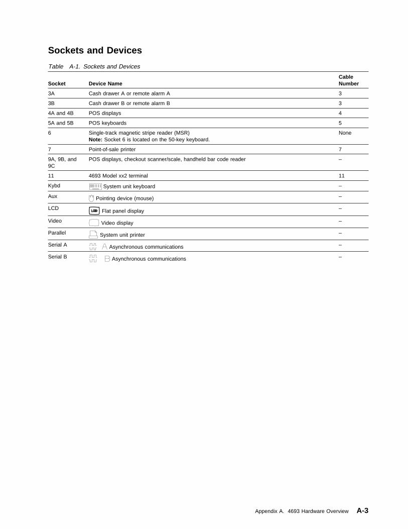
Sockets and Devices
Table A-1. Sockets and Devices
Socket
Device Name
CableNumber
3A Cash drawer A or remote alarm A 3
3B Cash drawer B or remote alarm B 3
4A and 4B POS displays 4
5A and 5B POS keyboards 5
6 Single-track magnetic stripe reader (MSR)Note: Socket 6 is located on the 50-key keyboard.
None
7 Point-of-sale printer 7
9A, 9B, and9C
POS displays, checkout scanner/scale, handheld bar code reader –
11 4693 Model xx2 terminal 11
Kybd System unit keyboard –
Aux Pointing device (mouse) –
LCD Flat panel display –
Video Video display –
Parallel System unit printer –
Serial A Asynchronous communications –
Serial B Asynchronous communications –
Appendix A. 4693 Hardware Overview A-3
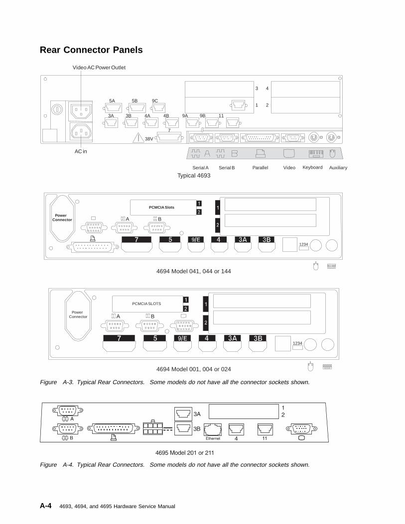
Rear Connector Panels
AC in
38V
Serial BSerial A
Video AC Power Outlet
Parallel Video Auxiliary
3 4
1 2
7
Keyboard
3A 3B 4A 4B 9A 9B 11
5A 5B 9C
Typical 4693
4694 Model 041, 044 or 144
4694 Model 001, 004 or 024
PowerConnector
PCMCIA Slots
A B
1234
PowerConnector
PCMCIA SLOTS
A B
1234
Figure A-3. Typical Rear Connectors. Some models do not have all the connector sockets shown.
Figure A-4. Typical Rear Connectors. Some models do not have all the connector sockets shown.
A-4 4693, 4694, and 4695 Hardware Service Manual

Description of 4693 Power Modes
Turning on Power to the 4693
The 4693 has no power ON/OFF switch. The Mode Control Switch on the operator panel is used toswitch between “Operational” Mode (ON) and “Non-Operational” Mode (OFF).
Throughout this manual, when you are instructed to Switch Ready mode ON, this means to press theMode Control Switch to turn the Ready indicator ON. When you are instructed to Switch Ready modeOFF, this means to press the Mode Control Switch to turn the Ready indicator OFF.
On: In this mode AC power is present at the terminal and the terminal is fully operational. The ReadyIndicator, and Indicators 1 and 2 will be ON.
Off: In this mode AC power is present at the terminal and Storage Retention is disabled. The ReadyIndicator is OFF. Indicators 1 and 2 will be ON. The terminal is not operational.
Standby: In this mode AC power is present at the terminal and Storage Retention is enabled. TheReady Indicator is OFF. Indicators 1 and 2 will be ON. The indicators are the same as in OFF mode butStorage Retention is enabled.
Backup: In this mode AC power is absent at the terminal and Storage Retention is enabled. Allindicators are OFF.
Power Down: In this mode AC power is absent at the terminal and Storage Retention is disabled. Allindicators are OFF.
Interlock Shutdown: In this mode AC power is present but the storage retention battery pack isdisconnected. This prevents the power supply from outputting any voltages. All indicators are OFF.
Table A-2. Power Mode Description
Mode
ACVoltage
ReadyIndicator
Indicator 1
Indicator 2
ON - Fully operational present ON ON ON
OFF - Storage retention disabled present OFF ON ON
STANDBY - Storage retention enabled present OFF ON ON
BACKUP - Storage retention enabledand battery power present
absent OFF OFF OFF
POWER DOWN - Storage retentiondisabled
absent OFF OFF OFF
INTERLOCK SHUTDOWN - Powersupply/battery interlock absent
present OFF OFF OFF
Appendix A. 4693 Hardware Overview A-5

A-6 4693, 4694, and 4695 Hardware Service Manual

Appendix B. Maintenance Inspection for the 4693
DANGER
Never work on equipment or connect or disconnect signal cables during periods oflightning activity.
CAUTION:For your safety, connect equipment requiring electrical power to a properly wired and groundedoutlet.
IBM products are designed to be safe during normal use, foreseeable misuse and under fault conditions.
Note: See Electrical Safety for IBM Customer Engineers, S229-8124.
An IBM maintenance inspection is to be performed as part of any alterations and attachments review onany IBM product presently on lease rental, maintenance agreement or per call service by IBM. If theinspection indicates the level of safeness of the IBM product is unacceptable it must be brought up to anacceptable level.
Maintenance Checklist for the 4693:
Note: All non-IBM devices and attachments must be removed from the 4693 unit before conducting themaintenance checklist. See the Hardware Service Manual for Point-of-Sale Input/Output Devices.
� Switch Ready mode OFF.� Disconnect the AC power cord from the wall receptacle.� Remove the front panel. See page 1-79.� Check the AC power cord for the following:
1. Use a meter to measure third-wire ground continuity for 0.1 ohms or less between the externalground pin and the frame of the power supply. Access the power supply frame at the rear nearthe fuse.
2. The AC power cord should not be frayed or damaged.� Check for non-IBM alterations. If any are present, has R009 non-IBM Alterations/Attachments Survey
been completed?� Check for damaged or missing insulation on wires.� Check for exposed electrical connections or terminals.� Check for the presence and condition of the following safety labels:
1. The safety label on the outside surface of the video display (if present) should read: “Hazardousvoltage. Do not remove this cover. No serviceable parts inside.”
2. Rechargeable battery labels should read: Ni Cd Return used batteries to IBM for disposal.� Check the inside of the system base unit for obvious unsafe conditions such as metal filings,
contamination, water or other fluids, or marks of fire or smoke damage.� Ensure that the voltage specified on the voltage label matches the voltage of the AC power cord.� Ensure that the fasteners that hold the top cover of the power supply are not missing and have not
been changed.� For models with batteries, check the condition of the battery.� Ensure that Ready mode is OFF and reinstall the front panel.� Connect the AC power cord to a power receptacle and ensure that the machine switches to Ready
mode ON.
Copyright IBM Corp. 1993, 1995 B-1

B-2 4693, 4694, and 4695 Hardware Service Manual

Appendix C. System maintenance
Customer / End User product care procedures . . . . . . . . . . . . . C - 1System unit . . . . . . . . . . . . . . . . . . . . . . . . . C-1Display . . . . . . . . . . . . . . . . . . . . . . . . . . . C-1Keyboard . . . . . . . . . . . . . . . . . . . . . . . . . . C-2Scanners . . . . . . . . . . . . . . . . . . . . . . . . . . C-2Service Provider System Maintenance P2ocedures. . . . . . . . . . . C-2
System Unit . . . . . . . . . . . . . . . . . . . . . . . . C-2Cash drawer . . . . . . . . . . . . . . . . . . . . . . . . C-2Display . . . . . . . . . . . . . . . . . . . . . . . . . . C-2Keyboard . . . . . . . . . . . . . . . . . . . . . . . . . C-2Keylocks . . . . . . . . . . . . . . . . . . . . . . . . . C-2Scanners . . . . . . . . . . . . . . . . . . . . . . . . . C-2Model 1 or 2 printer . . . . . . . . . . . . . . . . . . . . . C - 3Model 3 or 4 printer . . . . . . . . . . . . . . . . . . . . . C-3Model 4610 printer . . . . . . . . . . . . . . . . . . . . . C-4
Customer / End User product care proceduresOwners and users should periodically inspect their system unit and its componentsfor cleanliness and perform the following procedures based on usage andenvironmental characteristics, at a minimum of once every 12 months.
System unit1. Vacuum the exterior cover vent grills.
2. Clean the cover for cosmetic purposes as required.
v IBM suggests the use of a soft clean cloth with warm soapy water forcleaning the plastic parts on IBM product
v Use of a soft, dry cloth with isopropyl alcohol or any non abrasive and nonalkaline/ammonia/chloride based cleaner is permissible but somedeterioration in the finish could be seen.
3. Ensure that there is at least 51 mm (2 in.) clearance space around the unit.
Note: Do not apply cleaning solution directly to the cover. Always apply thecleaner on a clean cloth and then wipe the cover with the damp cloth. Becertain that the cloth is only damp and not dripping wet.
Display1. Clean the display covers for cosmetic purposes as required.
v IBM suggests the use of a soft clean cloth with warm soapy water forcleaning the plastic parts on IBM product.
v Use of a soft dry cloth with isopropyl alcohol or any nonabrasive and nonalkaline/ammonia/chloride based cleaner is permissible but somedeterioration in the finish could be seen.
Note: Do no apply cleaning solution directly to the cover. Always apply thecleaner on a clean cloth and then wipe the cover
Updated December 23, 2002
© Copyright IBM Corp. 1993, 2002 C-1
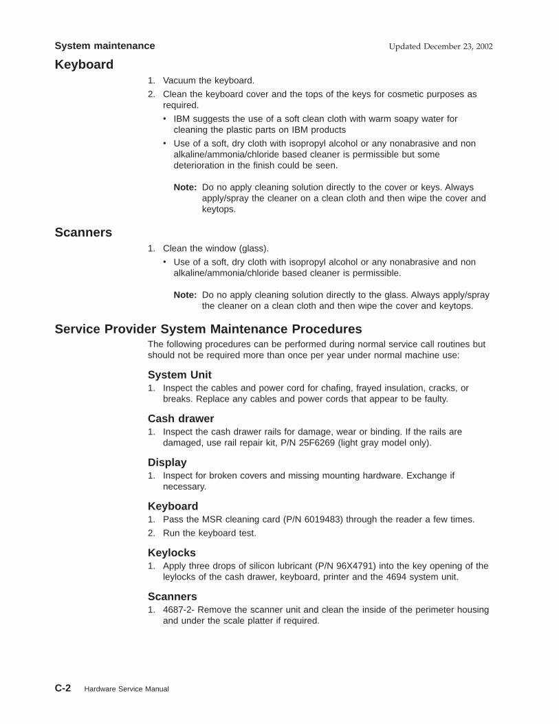
Keyboard1. Vacuum the keyboard.
2. Clean the keyboard cover and the tops of the keys for cosmetic purposes asrequired.
v IBM suggests the use of a soft clean cloth with warm soapy water forcleaning the plastic parts on IBM products
v Use of a soft, dry cloth with isopropyl alcohol or any nonabrasive and nonalkaline/ammonia/chloride based cleaner is permissible but somedeterioration in the finish could be seen.
Note: Do no apply cleaning solution directly to the cover or keys. Alwaysapply/spray the cleaner on a clean cloth and then wipe the cover andkeytops.
Scanners1. Clean the window (glass).
v Use of a soft, dry cloth with isopropyl alcohol or any nonabrasive and nonalkaline/ammonia/chloride based cleaner is permissible.
Note: Do no apply cleaning solution directly to the glass. Always apply/spraythe cleaner on a clean cloth and then wipe the cover and keytops.
Service Provider System Maintenance ProceduresThe following procedures can be performed during normal service call routines butshould not be required more than once per year under normal machine use:
System Unit1. Inspect the cables and power cord for chafing, frayed insulation, cracks, or
breaks. Replace any cables and power cords that appear to be faulty.
Cash drawer1. Inspect the cash drawer rails for damage, wear or binding. If the rails are
damaged, use rail repair kit, P/N 25F6269 (light gray model only).
Display1. Inspect for broken covers and missing mounting hardware. Exchange if
necessary.
Keyboard1. Pass the MSR cleaning card (P/N 6019483) through the reader a few times.
2. Run the keyboard test.
Keylocks1. Apply three drops of silicon lubricant (P/N 96X4791) into the key opening of the
leylocks of the cash drawer, keyboard, printer and the 4694 system unit.
Scanners1. 4687-2- Remove the scanner unit and clean the inside of the perimeter housing
and under the scale platter if required.
System maintenance Updated December 23, 2002
C-2 Hardware Service Manual

Model 1 or 2 printer1. Clean the print head, if required. See the IBM Store Systems: Hardware Service
Manual for Point-of-Sale Input/Output Devices for the print head cleaningprocedure.
2. Lubricate the carriage shaft, wear shoe skid-plate, and the print head guide rodshaft bearings with IBM #6 oil, if required.
3. Clean the teeth of the toggle gear, if required.
4. Exchange the carriage shaft wiper and saturate it with IBM #6 oil, if required.
Model 3 or 4 printer1. Clean the dust, fuzz balls, debris, and chad from the printer, if required.
2. Clean any dust and debris from the following sensors, if required.:v Home sensorv Cover sensorv Document insert (DI) upper and lower sensors (journal side)v Journal sensor
Note: If you clean the DI sensors, reset the sensor sensitivity. To reset:Press the Up Feed, Down Feed, and green buttons at the same time,open the cover and wait for the line feeding to stop. Then close thecover.
3. Clean the lead screw and black carrier shafts with a clean dry cloth, ifrequired. Do not lubricate lead screw or black carrier shafts, if required.
4. Inspect to see if the print wires are snagging the ribbon. This situation cancause home errors.
5. Inspect the ribbon drive clutch for proper (one-way) operation.
6. Inspect the DI rollers, if required. Clean using alcohol. Press the Up Feed orDown Feed buttons to move the rollers.
7. Inspect the Upper Forms Entry Shield for even clearance across platen faceand make sure that the shield is not trapped between the Platen and the PrintHead Assembly.
8. Inspect that the forms compensation system moves freely by feeding a thickform. The print head should move back as the feed rollers open up.
9. Inspect the two blue idler rollers and four paper bucket rollers for freemovement/rotation. Lubricate with #6 oil, if required.
10. Clear the debris around the platen rollers, if required
11. Oil the cutter blade pivots with #6 oil, if required. Wipe off any excess oil.
12. Inspect the metal bails that are used to hold the paper flush against the platen,in both the receipt and journal stations. Verify that the paper loads correctly.
13. On Models 3R and 4R printers, perform the following procedures:
v Clean the MICR read head and feed rollers.
v Inspect the MICR pressure pad for wear and damage.
v Exchange the document insert gears, if required. Use document insert gearkit P/N 73G2598.
v Run the stand-alone printer test and the MICR stand-alone tests when theprocedure is complete.
Helpful hints:
1. The microcode in the printer allows a change in horizontal and vertical characteralignment, which can compensate for wear in the printer. If the print line
System maintenanceUpdated December 23, 2002
Appendix B. System maintenance C-3

appears to be misaligned, use the appropriate printer adjustment procedure foryour terminal. See the IBM Store Systems: Hardware Service Manual forPoint-of-Sale Input/Output Devices.
2. If the printer is reporting false home errors, the problem may be the transportmotor, helix assembly, and nut.
3. The journal slip clutch or the O-ring can cause false journal out-of-paperconditions, which require opening the cover even though paper is present.
Model 4610 printer1. Run the printer offline tests. See the 4610 SureMark Point-of-Sale Printers
Hardware Service Manual.2. Clean the dust, fuzz balls, debris, and chad from the printer, if required.
System maintenance Updated December 23, 2002
C-4 Hardware Service Manual

Appendix D. Special Tools
To maintain point of sale terminals, the service representative may need the following items not suppliedin the tool kit:
� Keytop puller, P/N 1647720 (shipped with 4680 style keyboards)
� Lock cylinder alignment key, lock installation-removal key, and dummy lock insert key, P/N 4783922(shipped with the store controller)
� Miniprobes (two), P/N 453718
� Module extractor, P/N 9900764
� MSR cleaning card, P/N 6019483
� MSR test card, P/N 90X9640
� RS232 cable wrap plug, P/N 6165746 (shipped with the RS232 cable)
� Store loop cable test plug, P/N 61X3948 (shipped with the store loop cable)
� Store loop test cable, P/N 96X4967 (used when a non-IBM store loop cable is attached to the storecontroller)
� Wrap plug kit, P/N 96X5047
� Wrap plug for 4695 power supply, P/N 13H6231.
� Baseband network cable adapter, P/N 96X5037
� Baseband network terminator plug, P/N 96X4975
� Baseband network wrap plug, P/N 96X4974
� X.25 Interface Coprocessor/2 Wrap Plug
� Tri-connector wrap plug, P/N 72X8546 for serial and parallel ports.
Expendable Supplies� Paper for the point-of-sale printer, P/N 432768 (or equivalent)
� Print ribbon for the Models 1 and 2 point-of-sale printer, P/N 4483015 (or equivalent)
� Print ribbon for the Models 3 and 4 point-of-sale printer, P/N 1040888 (black) or IBM P/N 1040875(purple) or IBM P/N 1040900 (black auto-inking) (or equivalent)
Attention Failure to use the recommended ribbon may affect print head life and print quality.
Copyright IBM Corp. 1993, 1995 D-1

D-2 4693, 4694, and 4695 Hardware Service Manual

Appendix E. Collecting Vital Product Data for the 4693
Notes:
1. To enter and print vital product data using theIBM 4690 Operating System, use the IBM4690 Store System: Messages Guide.
2. When using any of the POS keyboard/MSRfamily of keyboards, the S1 and S2 functionsrequire a combination of two keys. First pressand hold the Ctrl key then press the S1 or S2key.
p.To collect vital product data for the 4693:
1. Use your store procedures to stop anyapplication programs that are running on the4693.
Switching Ready mode OFF
Switching Ready mode OFF at a 4693affects operations at all point-of-saleterminals attached to it.
2. Switch Ready mode OFF at the 4693.
3. Record the type, model, and serial number ofthe system unit. These numbers are printedon a label behind the front access panel.
4. Record the engineering change (EC) numberof the system board installed in your systemunit. This number is printed on the left edgeof the system board near the rear of theboard.
5. Record the EC number of the power supplyinstalled in your system unit. This number isprinted on a label on the right side of thepower supply.
Entering Vital Product Data Using the Reference DisketteNotes:
1. When using any of the POS keyboard/MSRfamily of keyboards, the S1 and S2 functionsrequire a combination of two keys. First pressand hold the Ctrl key then press the S1 or S2key.
2. When using one of the older 4680 typekeyboards, the S1 and S2 functions require acombination of two keys on some but only theS1 or S2 key on others. If a Ctrl key ispresent, a two key combination is required.When no Ctrl key is present, use only the S1or S2 key.
To enter vital product data using the referencediskette:
1. Use your store procedures to stop anyapplication programs that are running on the4693.
Switching Ready mode OFF
Switching Ready mode OFF at a 4693affects operations at all point-of-saleterminals attached to it.
2. Switch Ready mode OFF at the 4693.
3. Load the reference diskette. See “4693Configuration, Tests, and Utilities” onpage 1-64.
4. Select START UTILITIES from the MAINMENU.
5. Select ENTER/PRINT VITAL PRODUCTDATA from the UTILITY MENU.
6. Select ENTER VITAL PRODUCT DATA fromMENU UTILITY-2.
Note: To bypass an entry, press S2 (or Enteron the enhanced A/N keyboard). Theassignment of the alphabetic keys is shownon the following page.
Message T9801 displays.
7. Key in the 7-digit type and model numberexcluding the dash (-) and then press S2 (orEnter).
EXAMPLE: 4693541
Message T9802 displays.
Copyright IBM Corp. 1993, 1995 E-1

8. Key in the 7-digit serial number including thedash (-) and then press S2 (or Enter).
EXAMPLE: 23-12345
Message T9803 displays.
9. Key in the EC number of the system boardinstalled in your system unit and then pressS2 (or Enter). Message T9804 displays.
10. Key in the EC number of the power supplyinstalled in your system unit and then pressS2 (or Enter).
Note: To print and review the data justentered, see “Printing Vital Product DataUsing the Reference Diskette” on page E-4.
A
B
C
D
E
A
B
C
D
E
F
G
H
J
F
G
H
J
I
K
L
M
N
O
K
L
M
N
O
V
X
Y
Z
V
X
Y
Z
W7
4
1
7
4
1
8
5
2
8
5
2
9
6
3
/
9
6
3
/0
Q
R
S
T
U
Q
R
S
T
U
P
Dash-
S1 S2
CTRL
Figure E-1. RPOS Keyboard/Reader Key Assignments. This also applies to the RPOS Keyboard/Reader/Display.
A
B
C
D
E
F
G
H
I
J
K
L
M
N
O
P
Q
R
S
T
U
V
W
X
Y
Z
S1
S2
DASH
1 2 3
4 5 6
7 8 9
-0 /
CTRL
Figure E-2. Modifiable Layout Keyboard with Reader Key Assignments. This keyboard is sometimes referred to asML Keyboard/Reader.
E-2 4693, 4694, and 4695 Hardware Service Manual

A
B
C
D
E
A
B
C
D
E
F
G
H
J
F
G
H
J
I
K
L
M
N
O
K
L
M
N
O
V
X
Y
Z
V
X
Y
Z
W1
4
7
1
4
7
2
5
8
2
5
8
3
6
9
/
3
6
9
/0
S1
S2
Q
R
S
T
U
Q
R
S
T
U
P
Dash-
Figure E-3. 50-Key Keyboard Key Assignments and Combined Keyboard/Display Key Assignments. This figure isfor the older 4680 type keyboard.
Figure E-4. NANPOS Keyboard Key Assignments
Appendix E. Collecting Vital Product Data for the 4693 E-3

Printing Vital Product Data Using the Reference Diskette
Use this procedure to print the vital product data.
1. Use your store procedures to stop any
application programs that are running on the4693.
Switching Ready mode OFF
Switching Ready mode OFF at a 4693affects operations at all point-of-saleterminals attached to it.
2. Switch Ready mode OFF at the 4693.
3. Load the reference diskette. See “4693Configuration, Tests, and Utilities” onpage 1-64.
4. Select START UTILITIES from the MAINMENU.
5. Select ENTER/PRINT VITAL PRODUCTDATA from the UTILITY MENU.
6. Select PRINT VITAL PRODUCT DATA fromMENU UTILITY-2. The vital product data isprinted at the receipt station on the 4680printer attached to the 4693.
The vital product data is printed one itemper line. Each item represents a segmentof the vital product data for the selectedterminal.
The first four lines list:
Terminal typeTerminal serial numberEC number of the system boardEC number of the power supply
E-4 4693, 4694, and 4695 Hardware Service Manual

Appendix F. IBM Wireless LAN Return Codes
RC = 0B
Explanation: The remote workstation is not able to communicate to the wireless network because thebase station’s signal strength is too low.
User Response:
1 Check a remote workstation that is not too far from the base station to make sure it is operational.
2 Check the base station to make sure it is operational.
RC = 0E
Explanation: The remote workstation is not able to communicate to the wireless network because thebase station was not detected.
User Response:
1 Check a remote workstation that is not too far from the base station to make sure it is operational.
2 Check the base station to make sure it is operational.
3 Retry again later or reduce the number of workstations attached to the base station.
RC = 0F
Explanation: The base station adapter is overloaded.
User Response: Retry again later or reduce the number of workstations attached to this base station.
RC = 19
Explanation: The network name is mismatched with the base contacted.
User Response: Contact your network administrator for the correct network name. Change thewireless network name parameter to match the base.
RC = 1A
Explanation: The country code is mismatched with the base contacted.
User Response: Change the wireless network country code parameter to match the base.
RC = 1D
Explanation: The encryption code is mismatched with the base contacted.
User Response: Change the wireless network encryption code parameter to match the base.
RC = 20, 21, 22
Explanation: There is an internal adapter error occurring at adapter open time.
User Response: Retry the operation by booting the station. If the problem persists, run the IBMWireless LAN diagnostics.
Copyright IBM Corp. 1993, 1995 F-1

RC = 30
Explanation: The remote workstation is not able to communicate to the wireless network becausethere is too much interference.
User Response:
1 Check a remote workstation that is not too far from the base station to make sure it is operational.
2 Check the base station to make sure it is operational.
RC = 31
Explanation: The remote workstation is not able to communicate to the wireless network because thebase station that was selected was lost during registration time.
User Response:
1 Check a remote workstation that is not too far from the base station to make sure it is operational.
2 Check the base station to make sure it is operational.
RC = 3A, 3B, 3C, 3D, 3E
Explanation: There is an internal adapter error occurring at adapter open time.
User Response: Retry the operation by booting the station. If the problem persists, run the IBMWireless LAN diagnostics.
RC = 8A, 8B, 8C, 8D
Explanation: A timeout occurred. There is an internal adapter error occurring at adapter opening timebecause of a communication problem with the base station.
User Response: Run the IBM Wireless LAN diagnostics to ensure that the base station is operational.
RC = 90
Explanation: The workstation was not allowed to register to the wireless network because of accesscontrol.
User Response: Contact your network administrator to check the workstation’s allowed access.
Novell RPL ROM Error Messages
These Novell** RPL ROM error messages can occur when the terminal is attempting to connect to thenetwork. See the LAN documentation for your network for more detail on network problems.
RPL-ROM-ADR xxxx xxxx xxxx
Explanation: Six byte node universal adapter address (UAA) of the installed adapter.
User Response:
1 Make sure that the cable is securely connected to the radio module and to the adapter card.
2 Make sure that the adapter card is securely connected.
3 Contact your network administrator for assistance.
F-2 4693, 4694, and 4695 Hardware Service Manual
RPL-ROM-DMA nn
Explanation: One byte decimal field containing the DMA channel used by the adapter.
User Response:
1 Make sure that the cable is securely connected to the radio module and to the adapter card.
2 Make sure that the adapter card is securely connected.
3 Contact your network administrator for assistance.
RPL-ROM-IRQ nn
Explanation: One byte decimal field containing the interrupt number used by the adapter.
User Response:
1 Make sure that the cable is securely connected to the radio module and to the adapter card.
2 Make sure that the adapter card is securely connected.
3 Contact your network administrator for assistance.
RPL-ROM-PIO xxxx
Explanation: A two byte hexadecimal field containing the I/O address used by the adapter.
User Response:
1 Make sure that the cable is securely connected to the radio module and to the adapter card.
2 Make sure that the adapter card is securely connected.
3 Contact your network administrator for assistance.
RPL-ROM-SLT xxxx
Explanation: A two byte hexadecimal field containing the slot number used by the Micro Channeladapter.
User Response:
1 Make sure that the cable is securely connected to the radio module and to the adapter card.
2 Make sure that the adapter card is securely connected.
3 Contact your network administrator for assistance.
RPL-ROM-FFC nnnn
Explanation: A decimal field containing the number of find frames sent by the boot ROM. Anexcessive find frame count indicates that the RPL server is not present or is not able to communicatewith the remote workstation.
User Response: If the problem is the remote workstation, exchange the IBM Wireless Adapter card inthe remote workstation. If the problem is the server, contact your network administrator for assistance.
RPL-ROM-SFC nnnn
Explanation: A decimal field containing the number of send file request frames sent by the bootROM. An excessive send file request count indicates that the RPL server is not responding after it hasbeen found.
User Response: Contact your network administrator for assistance.
Appendix F. IBM Wireless LAN Return Codes F-3

RPL-ROM-SEQ nnnn
Explanation: A decimal field containing the number specifying the last valid sequence numberreceived.
User Response: Contact your network administrator for assistance.
RPL-ROM-ERR cccc RPL halted
Explanation: A fatal error from either the driver or the boot ROM occurred.
User Response: Possible cccc error codes include:
� BADA – There is an error in the file data response from the server containing a locate or transferaddress that is not valid.
� DExx – There is an error from the driver HSM that issued a DOS interrupt, function code xx that isnot valid.
Contact your network administrator for assistance.
F-4 4693, 4694, and 4695 Hardware Service Manual

Index
Numerics4693
configuration 1-64how to read POST messages 1-9locations 1-77logic tray 1-83messages 1-8operator panel 1-1, A-2POST message index 1-10power modes A-5power supply 1-51, 1-55, 1-81system maintenance C-1problem determination 1-2removals and replacements 1-77retrieving network RPL messages 1-9symptoms 1-47tests 1-64utilities 1-64
4694configuration 2-9locations 2-11messages 2-5preliminary checklist 2-2problem determination 2-1, 2-2service diskette 2-8symptoms 2-3tests 2-8utilities 2-9
4694 models 001,004,024covers 2-12diskette drive 2-13fixed disk 2-13memory modules 2-16PCMCIA card 2-14power supply 2-14removals and replacements 2-11riser card 2-14terminal system board 2-15VGA card 2-13
4694 models 041,044covers 2-17diskette drive 2-18fixed disk 2-18logic and power supply tray 2-17memory modules 2-20PCMCIA card 2-20power supply 2-19removals and replacements 2-17riser card 2-20terminal system board 2-20
4695configuration 3-55, 3-56configuring 3-2creating 3-56device test menu 3-3diskette drive 3-41fixed disk 3-40front panel 3-34lock assembly FRUs 3-48main menu 3-3memory modules 3-40messages 3-21POST 3-21POST beep codes, 4695 3-26power button 3-47problems 3-1rear connector panel 3-34removals and replacements, models 002 and
021 3-10removing power-on password 3-4run-time error messages 3-27running setup, 4695 3-56service diskette 3-2service diskette messages 3-32service level update diskette 3-4symptoms, model 002 and 012 3-6symptoms, Models 201 and 211 3-19system board 3-42, 3-43test error messages 3-28test menu 3-3tests 3-2top cover, 4695 3-39using 3-57
4695 Point-of-Sale Adapter 3-444695 service diskette menus 3-2
Bbacklight, 4695 3-38base memory address, 4695 3-9blank lock inserts, 4695 3-50
Ccable sockets and devices, 4693 A-3cabling publications xiiiconfiguration
4693 1-644694 2-8, 2-94695 I/O address 3-94695 memory address 3-9interrupt select, 4695 3-9
Copyright IBM Corp. 1993, 1995 X-1

configuration (continued)primary adapter, 4695 3-9secondary adapter, 4695 3-9
configuration, Models 201 and 211 3-55, 3-56covers
4693 1-774694 - 001,004,024 2-124694 - 041,044, 144 2-174695 3-10
customer display lens, 4695 3-53
Ddisk drive
See fixed diskdiskette drive 3-41
4693 1-56, 1-824694 2-34694 - 001,004,024 2-134694 - 041,044 2-18
Eelectronic discharge (ESD) xelectronic emission notices ixerror codes
See messagesexpansion feature, installing 3-44expendable supplies
point-of-sale printer paper D-1point-of-sale printer ribbon cartridge D-1
Ffailures
See symptomsFCC information ixfeature adapter
See optional adapterfeature card
See optional adapterfixed disk
4693 1-55, 1-844694 2-34694 - 001,004,024 2-134694 - 041,044 2-18
fixed disk, 4695 3-40front door, 4695 3-52front panel 3-41front panel, 4695 Models 201 and 211 3-34front view of the 4693 A-2
Ggeneral safety considerations ix
II/O address configuration 3-9I/O connectors A-3I/O devices
4693 1-64interrupt select configuration 3-9
Llibrary, 4693/4694/4695 xiilithium battery, 4695 3-53locations
4693 1-774694 2-11
lock assembly FRUs, 4695 3-48lock insert, 4695 3-49lower wedge, 4695 3-51
Mmagnetic strip reader, (MSR) 3-36memory address configuration 3-9memory modules 3-40messages
4693 1-84694 2-5
messages, 4695 3-21mode control switch operation, 4693 A-5
Nnetwork
4693 1-8, 1-47
Ooperator panel
4693 1-1, 1-3, 1-51, 1-80optional adapter
4693 1-8, 1-47, 1-64, 1-85
PPCMCIA feature 3-54POST beep codes, 4695 3-26POST messages, 4695 3-21power button, 4695 3-47power supply
4693 1-51, 1-814694 2-34694 - 001,004,024 2-144694 - 041,044, 144 2-19
power-on password, 4695 3-4preventive maintenance C-1primary adapter configuration, 4695 3-9
X-2 4693, 4694, and 4695 Hardware Service Manual

problem determination4693 1-1, 1-24694 2-1, 2-24695 3-1
publications, related hardware xiiipublications, related software xiii
Rready indicator, 4693 A-5rear connector panel, 4695 Models 201 and 211 3-34rear connector panels A-3rear door, 4695 3-52related publications, hardware xiiirelated publications, software xiiiremoving and replacing FRUs
4693 1-774694 - 001,004,024 2-114694 - 041,044, 144 2-174695 models 002 and 021 3-10
return codes, wireless F-1run-time error messages, 4695 3-27
Ssafety notices ixsecondary adapter configuration, 4695 3-9service diskette messages, 4695 3-32service level update 3-4service marks viiisetup diskette, 4695 3-56setup program, Models 201 and 211 3-55socket locations A-3special tools D-1store system library xiisupplies
See expendable suppliessupply item part numbers D-1symptoms
4693 1-474694 2-34695 models 002, 012 3-6
system board, 4695 3-42system partition 1-65system unit
See 4693See 4694See 4695
Ttablet 3-36tablet latch, 4695 3-51terminal system board
4693 1-864694 - 001,004,024 2-15
terminal system board (continued)4694 - 041,044 2-20
test card D-1test error messages, 4695 3-28tests
4693 1-644694 2-8
tools D-1trademarks viiitroubleshooting
See problem determination
Uupper wedge, 4695 3-50utilities
4693 1-644694 2-9
VVGA card, 4694 2-13
Wwireless return codes F-1wrap plug D-1
Index X-3

Tell Us What You Think!
4693, 4694, and 4695 Point-of-Sale Terminals: Hardware Service Manual
Publication No. SY27-0337-02
We hope you find this publication useful, readable, and technically accurate, but only you can tell us!Your comments and suggestions will help us improve our technical publications. Please take a fewminutes to let us know what you think by completing this form. If you are in the U.S.A., you can mail thisform postage free or fax it to us at 1-800-253-3520. Elsewhere, your local IBM branch office orrepresentative will forward your comments or you may mail directly to us.
Specific comments or problems:
Please tell us how we can improve this book:
Thank you for your comments. If you would like a reply, provide the necessary information below.
Name Address
Company or Organization
Phone No.
Overall, how satisfied are you with the information in this book? Satisfied Dissatisfied
Ø Ø
How satisfied are you that the information in this book is: Satisfied Dissatisfied
Accurate Ø ØComplete Ø ØEasy to find Ø ØEasy to understand Ø ØWell organized Ø ØApplicable to your task Ø Ø

Cut or FoldAlong Line
Cut or FoldAlong Line
Tell Us What You Think!SY27-0337-02 IBM
Fold and Tape Please do not staple Fold and Tape
NO POSTAGENECESSARYIF MAILED IN THEUNITED STATES
BUSINESS REPLY MAILFIRST-CLASS MAIL PERMIT NO. 40 ARMONK, NEW YORK
POSTAGE WILL BE PAID BY ADDRESSEE
Design & Information DevelopmentDept. CJMA/Bldg. 645International Business Machines CorporationPO BOX 12195RESEARCH TRIANGLE PARK NC 27709-9990
Fold and Tape Please do not staple Fold and Tape
SY27-0337-02


IBM
Printed in U.S.A.
SY27-ð337-ð2