Hardware Design Guide Version 2.0 for Microsoft · Web viewThese guidelines address the...
245
Hardware Design Guide Version 2.0 for Microsoft Windows NT Server A Reference for Designing Servers and Peripherals for the Microsoft® Windows NT® Server Operating System Intel Corporation and Microsoft Corporation Publication Date: July 22, 1998
Transcript of Hardware Design Guide Version 2.0 for Microsoft · Web viewThese guidelines address the...
Hardware Design Guide Version 2.0 for Microsoft Windows NT Server
A Reference for Designing Servers and Peripherals for the Microsoft® Windows NT® Server Operating System
Intel Corporation and Microsoft CorporationPublication Date: July 22, 1998
ii
The information contained in this document represents the current view of Intel Corporation and Microsoft Corporation on the issues discussed as of the date of publication. Because Intel and Microsoft must respond to changing market conditions, it should not be interpreted to be a commitment on the part of Intel and Microsoft, and Intel and Microsoft cannot guarantee the accuracy of any information presented. This document is for informational purposes only. INTEL AND MICROSOFT MAKE NO WARRANTIES, EXPRESS OR IMPLIED, IN THIS DOCUMENT.
Intel Corporation and Microsoft Corporation may have patents or pending patent applications, trademarks, copyrights, or other intellectual property rights covering subject matter in this document. The furnishing of this document does not give you any license to these patents, trademarks, copyrights, or other intellectual property rights.
Intel and Microsoft do not make any representation or warranty regarding specifications in this document or any product or item developed based on these specifications. Intel and Microsoft disclaim all express and implied warranties, including but not limited to the implied warranties of merchantability, fitness for a particular purpose, and freedom from infringement. Without limiting the generality of the foregoing, Intel and Microsoft do not make any warranty of any kind that any item developed based on these specifications, or any portion of a specification, will not infringe any copyright, patent, trade secret, or other intellectual property right of any person or entity in any country. It is your responsibility to seek licenses for such intellectual property rights where appropriate. Intel and Microsoft shall not be liable for any damages arising out of or in connection with the use of these specifications, including liability for lost profit, business interruption, or any other damages whatsoever.
ActiveX, BackOffice, DirectShow, DirectX, Microsoft, MS-DOS, NetShow, Win32, Windows, Windows NT, and the Windows logo are either registered trademarks or trademarks of Microsoft Corporation in the United States and/or other countries.
Intel and Pentium are registered trademarks, and Intel486, MMX, and Xeon are trademarks of Intel Corporation.
Other product and company names herein may be the trademarks of their respective owners.
© 1997–1998 Intel Corporation and Microsoft Corporation. All rights reserved.
This document is not for sale. To obtain additional copies of this document, please download the source files from the web sites at http://www.intel.com/procs/servers/ or http://www.microsoft.com/hwdev/serverdg.htm.
Hardware Design Guide Version 2.0 for Microsoft Windows NT Server © 1997-1998 Intel Corporation and Microsoft Corporation. All rights reserved. Published: July 22, 1998 — Printed: 09/23/98 03:52 PM
iii
Contents
WelcomeHow to Use This Guide...............................................................................................Conventions Used in This Guide.................................................................................
Conventional Terms..............................................................................................Required vs. Recommended Features in This Guide..............................................Requirements by Server Class and Operating System Product................................
References and Resources...........................................................................................Server Design Information from Intel and Microsoft..............................................Hardware Design Guide Compliance and Testing Programs..................................Information Resources and Technical References..................................................
Acknowledgments......................................................................................................CHAPTER 1 Overview of Server Design IssuesIntroduction to Design Issues......................................................................................Server Classes and Operating System Editions............................................................Designing Systems for Windows NT Server................................................................Preparing for ACPI and OnNow Design......................................................................Microprocessor Architecture.......................................................................................CHAPTER 2 System Component RequirementsGeneral Component Requirements..............................................................................System Microprocessor Requirements.........................................................................Memory Requirements................................................................................................ACPI and Power Management Requirements..............................................................Startup Support Requirements.....................................................................................Plug and Play Requirements.......................................................................................Device Bay Requirements...........................................................................................CHAPTER 3 Bus and Device RequirementsI/O Bus Requirements.................................................................................................USB Requirements.....................................................................................................Other Bus Requirements.............................................................................................Device Requirements..................................................................................................CHAPTER 4 Networking and Communications RequirementsNetwork Adapter Requirements..................................................................................Modem Requirements.................................................................................................
Server Types and Modem Usage............................................................................Design Issues for Server Modems..........................................................................
ATM Requirements....................................................................................................ADSL Requirements...................................................................................................Cable Modem Requirements.......................................................................................ISDN Requirements....................................................................................................
Serial ISDN Modems.......................................................................................Parallel ISDN Devices......................................................................................
IrDA Requirements for Communications....................................................................CHAPTER 5 Storage Device RequirementsStorage Device General Requirements........................................................................SCSI Controllers and Peripherals................................................................................
Hardware Design Guide Version 2.0 for Microsoft Windows NT Server © 1997-1998 Intel Corporation and Microsoft Corporation. All rights reserved. Published: July 22, 1998 — Printed: 09/23/98 03:52 PM
iv
ATA Controllers and Peripherals................................................................................Fibre Channel Controllers and Peripherals..................................................................Erasable Disk Drives...................................................................................................CD and DVD Drives...................................................................................................
CD Drive Requirements.........................................................................................DVD Drive Requirements......................................................................................
Tape Drives................................................................................................................Media Changers..........................................................................................................
CD Changers.........................................................................................................Tape and Optical Disk Changers............................................................................
CHAPTER 6 Physical Design and Hardware Security RequirementsPhysical Design Requirements....................................................................................Hardware Security Requirements................................................................................CHAPTER 7 Reliability, Availability, and Serviceability RequirementsBackup and Reliability Requirements.........................................................................
Backup Hardware..................................................................................................Power Supply........................................................................................................Fault-Tolerant Hardware........................................................................................Serviceability Requirements..................................................................................
High Availability Requirements..................................................................................Manageability Baseline Requirements........................................................................
General Manageability Baseline Requirements......................................................Manageability Component Instrumentation Requirements.....................................
APPENDIX A Server Requirements ChecklistGlossaryIndex
Hardware Design Guide Version 2.0 for Microsoft Windows NT Server © 1997-1998 Intel Corporation and Microsoft Corporation. All rights reserved. Published: July 22, 1998 — Printed: 09/23/98 03:52 PM
v
Hardware Design Guide Version 2.0 for Windows NT Server is for engineers who build server systems, expansion cards, and peripheral devices that use the Microsoft® Windows NT® Server operating system.
This guide is co-authored by Intel Corporation and Microsoft Corporation. The requirements and recommendations in this guide indicate features that the hardware industry should consider in designing servers and peripherals for various price levels and performance levels.
This guide includes design guidelines for servers that will run any version of the Windows NT Server operating system. These guidelines address the following design issues:
Features for basic commodity server design alternatives for small office/home office (SOHO) and Enterprise servers.
Requirements for implementing the OnNow design initiative, including those related to the Advanced Configuration and Power Interface (ACPI) specification, Plug and Play device configuration, and power management in server systems.
Implementation of devices supported under Windows NT Server. Manageability features that help to reduce total cost of ownership (TCO)
under Windows NT Server by providing support for maximum automation of administrative tasks with centralized control and maximum flexibility.
Important: Implementing these guidelines produces servers that deliver an enhanced user experience with the Windows NT Server operating system. These requirements are not related to the minimum, most-optimal, or best system requirements for running the Windows NT Server operating system. For information about the minimum system requirements for running Windows NT Server, see the web site at http://www.microsoft.com/ntserver/.
Hardware Design Guide Version 2.0 for Microsoft Windows NT Server © 1997-1998 Intel Corporation and Microsoft Corporation. All rights reserved. Published: July 22, 1998 — Printed: 09/23/98 03:52 PM
Welcome
Welcome vi
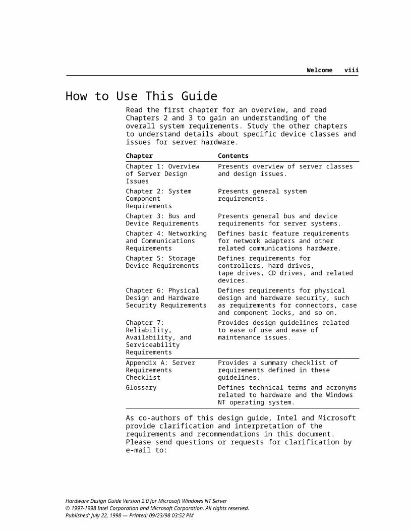
How to Use This GuideRead the first chapter for an overview, and read Chapters 2 and 3 to gain an understanding of the overall system requirements. Study the other chapters to understand details about specific device classes and issues for server hardware.
Chapter Contents
Chapter 1: Overview of Server Design Issues
Presents overview of server classes and design issues.
Chapter 2: System Component Requirements
Presents general system requirements.
Chapter 3: Bus and Device Requirements
Presents general bus and device requirements for server systems.
Chapter 4: Networking and Communications Requirements
Defines basic feature requirements for network adapters and other related communications hardware.
Chapter 5: Storage Device Requirements
Defines requirements for controllers, hard drives, tape drives, CD drives, and related devices.
Chapter 6: Physical Design and Hardware Security Requirements
Defines requirements for physical design and hard-ware security, such as requirements for connectors, case and component locks, and so on.
Chapter 7: Reliability, Availability, and Serviceability Requirements
Provides design guidelines related to ease of use and ease of maintenance issues.
Appendix A: Server Requirements Checklist
Provides a summary checklist of requirements defined in these guidelines.
Glossary Defines technical terms and acronyms related to hardware and the Windows NT operating system.
As co-authors of this design guide, Intel and Microsoft provide clarification and interpretation of the requirements and recommendations in this document. Please send questions or requests for clarification by e-mail to:
[email protected]@microsoft.com
Hardware Design Guide Version 2.0 for Microsoft Windows NT Server© 1997-1998 Intel Corporation and Microsoft Corporation. All rights reserved. Published: July 22, 1998 — Printed: 09/23/98 03:52 PM
Welcome vii
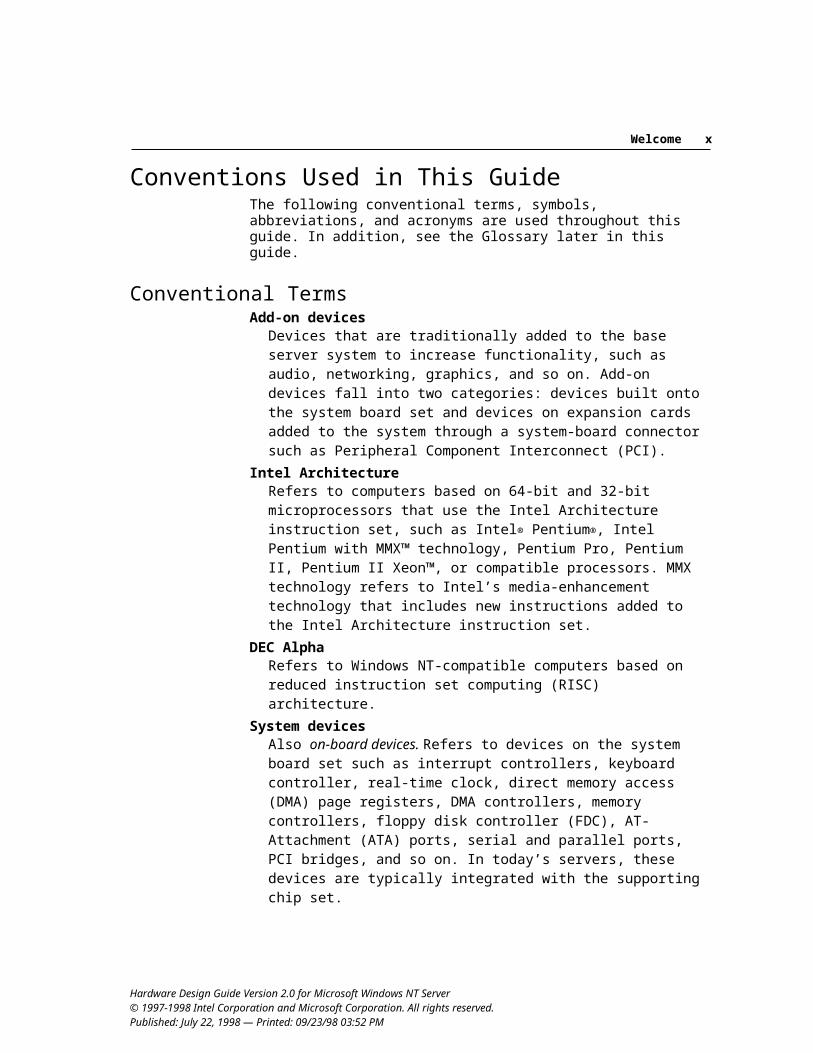
Conventions Used in This GuideThe following conventional terms, symbols, abbreviations, and acronyms are used throughout this guide. In addition, see the Glossary later in this guide.
Conventional TermsAdd-on devices
Devices that are traditionally added to the base server system to increase functionality, such as audio, networking, graphics, and so on. Add-on devices fall into two categories: devices built onto the system board set and devices on expansion cards added to the system through a system-board connector such as Peripheral Component Interconnect (PCI).
Intel ArchitectureRefers to computers based on 64-bit and 32-bit microprocessors that use the Intel Architecture instruction set, such as Intel® Pentium®, Intel Pentium with MMX™ technology, Pentium Pro, Pentium II, Pentium II Xeon™, or compatible processors. MMX technology refers to Intel’s media-enhancement technology that includes new instructions added to the Intel Architecture instruction set.
DEC AlphaRefers to Windows NT-compatible computers based on reduced instruction set computing (RISC) architecture.
System devicesAlso on-board devices. Refers to devices on the system board set such as interrupt controllers, keyboard controller, real-time clock, direct memory access (DMA) page registers, DMA controllers, memory controllers, floppy disk controller (FDC), AT-Attachment (ATA) ports, serial and parallel ports, PCI bridges, and so on. In today’s servers, these devices are typically integrated with the supporting chip set.
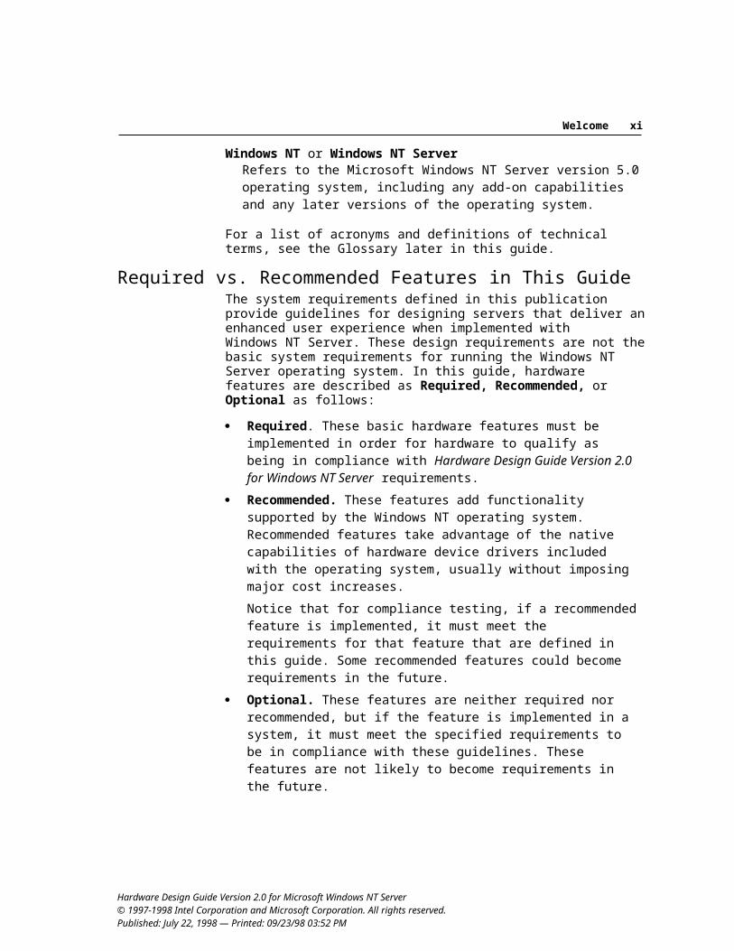
Windows NT or Windows NT ServerRefers to the Microsoft Windows NT Server version 5.0 operating system, including any add-on capabilities and any later versions of the operating system.
For a list of acronyms and definitions of technical terms, see the Glossary later in this guide.
Hardware Design Guide Version 2.0 for Microsoft Windows NT Server© 1997-1998 Intel Corporation and Microsoft Corporation. All rights reserved. Published: July 22, 1998 — Printed: 09/23/98 03:52 PM
Welcome viii
Required vs. Recommended Features in This GuideThe system requirements defined in this publication provide guidelines for design-ing servers that deliver an enhanced user experience when implemented with Windows NT Server. These design requirements are not the basic system require-ments for running the Windows NT Server operating system. In this guide, hard-ware features are described as Required, Recommended, or Optional as follows:
Required. These basic hardware features must be implemented in order for hardware to qualify as being in compliance with Hardware Design Guide Version 2.0 for Windows NT Server requirements.
Recommended. These features add functionality supported by the Windows NT operating system. Recommended features take advantage of the native capabilities of hardware device drivers included with the operating system, usually without imposing major cost increases.Notice that for compliance testing, if a recommended feature is implemented, it must meet the requirements for that feature that are defined in this guide. Some recommended features could become requirements in the future.
Optional. These features are neither required nor recommended, but if the feature is implemented in a system, it must meet the specified requirements to be in compliance with these guidelines. These features are not likely to become requirements in the future.
In this guide, the following terms are used in regard to the requirements:
Must: Required Should: Recommended
Note: It is recognized that original equipment manufacturers (OEMs) supply systems with specific feature requirements to corporations, where customers integrate the desired solution on site. For example, a customer could specify a minimum configuration without disk drives.
Systems designed for specific corporate customers are exempt from related minimum requirements defined in this guide. Such exemptions are noted in this document. However, for compliance testing of these requirements, the system must include at least the minimum required components.
Requirements by Server Class and Operating System ProductRequirements for three different Windows NT operating system products and three server classes are designated in these guidelines. The operating system products include:
Microsoft Windows NT Server Microsoft Windows NT Server/Enterprise Edition Microsoft BackOffice® Small Business Server
Hardware Design Guide Version 2.0 for Microsoft Windows NT Server© 1997-1998 Intel Corporation and Microsoft Corporation. All rights reserved. Published: July 22, 1998 — Printed: 09/23/98 03:52 PM
Welcome ix
The server classes in this guide are the same as in Version 1.0: Basic Server, Enterprise Server, and SOHO Server. (For more information, see Chapter 1, “Overview of Server Design Issues.”) For ease of use in this guide, Basic, SOHO, and Enterprise class requirements are all defined together in the main body of the document, rather than in separate chapters.
Any class of server can run any server operating system product. Furthermore, there are no direct relationships that define which operating system product can or should run on each specific class of server. However, server platforms might need to meet additional requirements to meet the goals of a specific server class or to be a good target platform for a specific operating system.
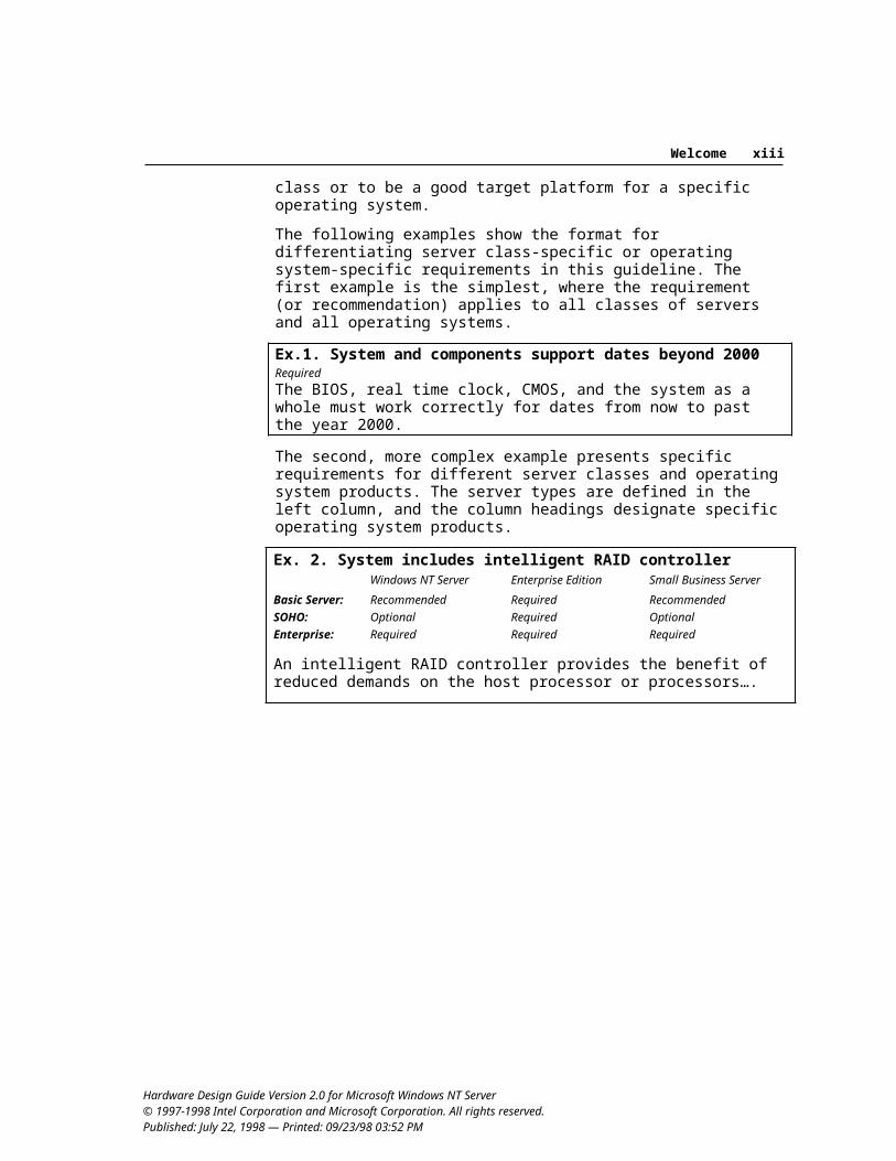
The following examples show the format for differentiating server class-specific or operating system-specific requirements in this guideline. The first example is the simplest, where the requirement (or recommendation) applies to all classes of servers and all operating systems.
Ex.1. System and components support dates beyond 2000RequiredThe BIOS, real time clock, CMOS, and the system as a whole must work correctly for dates from now to past the year 2000.
The second, more complex example presents specific requirements for different server classes and operating system products. The server types are defined in the left column, and the column headings designate specific operating system products.
Ex. 2. System includes intelligent RAID controllerWindows NT Server Enterprise Edition Small Business Server
Basic Server: Recommended Required RecommendedSOHO: Optional Required OptionalEnterprise: Required Required Required
An intelligent RAID controller provides the benefit of reduced demands on the host processor or processors….
Hardware Design Guide Version 2.0 for Microsoft Windows NT Server© 1997-1998 Intel Corporation and Microsoft Corporation. All rights reserved. Published: July 22, 1998 — Printed: 09/23/98 03:52 PM
Welcome x
References and ResourcesThe following represents some of the information resources, services, and tools available to help build hardware optimized to meet the requirements defined in this guide. This section also lists technical references for the specifications cited in this guide.
Server Design Information from Intel and MicrosoftAdditional information relating to server hardware design is available from Intel Corporation at:
http://www.intel.com/procs/servers/http://developer.intel.com/solutions/platfms/server.htmE-mail: [email protected]
Additional information about related hardware design guide issues and Windows NT Server hardware is available from the Microsoft web sites at:
http://www.microsoft.com/hwdev/http://www.microsoft.com/ntserver/
Hardware Design Guide Compliance and Testing Programs A specific hardware model is compatible with Windows NT if it has a Windows NT device driver designed to interact with that hardware model, and if Windows NT and that driver interoperate with the hardware in a stable manner.
Hardware Compatibility Tests (HCTs). Microsoft evaluates hardware compatibility using the Windows NT HCTs, which are run to test the interaction between device drivers and hardware. These tests issue the full range of commands available to applications and operating system software, and they stress hardware beyond the level of most real-world situations. The Windows NT HCT team runs the tests and reports results to the manufacturer. You can obtain a Windows NT HCT kit from the Windows Hardware Quality Labs (WHQL) web site at http://www.microsoft.com/hwtest/testkits/.
Hardware Compatibility List (HCL). Hardware that passes the HCTs is eligible to be included on the Windows NT HCL, available to customers by way of the World Wide Web and other sources. The HCL helps interested parties identify hardware and software that has been verified to run on Windows NT Server.
WHQL administers the hardware compliance testing programs at Microsoft. Hardware developers whose products pass the WHQL testing program receive a detailed report about how the system runs Windows NT Server based on the results of the testing. Hardware that passes testing is included on the Windows HCL at http://www.microsoft.com/hwtest/hcl/.
Hardware Design Guide Version 2.0 for Microsoft Windows NT Server© 1997-1998 Intel Corporation and Microsoft Corporation. All rights reserved. Published: July 22, 1998 — Printed: 09/23/98 03:52 PM
Welcome xi
Compliance Dates. Typically, these hardware design requirements go into effect on July 1, 1999, and are applicable to servers that are designed and built after this document’s initial publication date. Compliance testing for some requirements may begin later because of the time required for technology changes to become widely available. For information about actual compliance testing dates for specific requirements, or about any of the hardware testing programs at Microsoft, contact WHQL:
Windows Hardware Quality Labs Microsoft Corporation One Microsoft Way Redmond, WA 98052-6399 USA
http://www.microsoft.com/hwtest/E-mail: [email protected]: (425) 703-3872
Information Resources and Technical ReferencesInformation Resources
Common Information Model (CIM)http://www.dmtf.org/work/cim.html
Desktop Management Task Force (DMTF)http://www.dmtf.org
Intel developer informationhttp://developer.intel.com
Microsoft hardware developer information http://www.microsoft.com/hwdev/
Microsoft Developer Network (MSDN) Professional membershipPhone: (800) 759-5474Outside North America: (510) 275-0763Fax: (510) 275-0762 http://www.microsoft.com/msdn/
Microsoft Windows Hardware Quality Labs (WHQL)[email protected]://www.microsoft.com/hwtest/
Technical References
1997 Version of National ISDN Basic Rate Interface Terminal Equipment Generic Guidelines, Document Number SR-3888
http://www.bellcore.comAdvanced Configuration and Power Interface Specification, Version 1.0
http://www.teleport.com/~acpi/Advanced RISC Computing Multiprocessor Standard Specification, Revision 1.0, May 4, 1992
http://www.microsoft.com/hwdev/specs/
Hardware Design Guide Version 2.0 for Microsoft Windows NT Server© 1997-1998 Intel Corporation and Microsoft Corporation. All rights reserved. Published: July 22, 1998 — Printed: 09/23/98 03:52 PM
Welcome xii
An Interoperable End-to-End Broadband Service Architecture over ADSL Systemhttp://www.microsoft.com/hwdev/publicnet/ (Version 3.0 or later)
AT Attachment 2 [X3T9.2 948D] and other ATA standardsAT Attachment 3 [X3T10 2008D] standardATA/ATAPI-4 StandardATA Packet Interface for CD-ROM, SFF 8020iATAPI Removable Media BIOS Specification (ARMD)
Global Engineering DocumentsFax: (303) 397-2740Phone: (800) 854-7179 (U.S.)
(613) 237-4250 (Canada)(303) 792-2181 (Outside North America)
ATM User-Network Interface Specification, Version 3.1Prentice Hall, 1995; ISBN 0-13-393828-Xhttp://www.atmforum.com
Desktop Management Interface Specification, Version 2.0DMI Compliance Guidelines, Version 1.0
http://www.dmtf.org/tech/specs.htmlDevice Class Power Management Specifications
http://www.microsoft.com/hwdev/onnow.htmEl Torito — Bootable CD-ROM Format Specification, Version 1.0Compaq, Intel, Phoenix BIOS Boot Specification, Version 1.01
http://www.ptltd.com/techs/specs.htmlEuropean Telecommunications Standards Institute (ETSI) or Global System for Mobile (GSM) standards
Phone: +33-92 94 42 00FAX: +33-93 65 47 16E-mail: [email protected]
Fibre Channel Associationhttp://www.amdahl.com/ext/carp/fca/fca.html
I2O (Intelligent I/O) Architecture Specification, Version 1.5http://www.intel.com/design/iio/i2osig.htmhttp://www.i2osig.org (special interest group)
IBM Personal System/2 Common Interfaces, Part No. S84F-9809IBM Personal System/2 Mouse Technical Reference, Part No. S68X-2229
International Business Machines CorporationIBM Customer Publications Support: (800) 879-275Or contact an IBM sales representative
IEEE 1394 StandardsTelephone: (800) 949-4333Fax: (410) 259-5045Released Standards: Global Engineering Documents
Hardware Design Guide Version 2.0 for Microsoft Windows NT Server© 1997-1998 Intel Corporation and Microsoft Corporation. All rights reserved. Published: July 22, 1998 — Printed: 09/23/98 03:52 PM
Welcome xiii
Information Technology Enhanced BIOS Services for Disk Drives [T13-1226DT]ftp://fission.dt.wdc.com/pub/standards/x3t13/project/
ITU Communications StandardsPhone: (41) (22) 730-6141Fax: (41) (22) 730-5194E-mail: [email protected]
Interoperability Specification for ICCs and Personal Computer Systemshttp://www.smartcardsys.com
MCNS Documentshttp://www.cablemodem.org
Media Status Notification, Version 1.03http://www.microsoft.com/hwdev/respec/
Microsoft Platform SDK and Windows NT 5.0 DDK, including Network Driver Interface Specification (NDIS) 5.0 documentation
Provided through MSDN Professional membership; http://www.microsoft.com/msdn/
Microsoft Windows Hardware Compatibility List (HCL)http://www.microsoft.com/hwtest/hcl/
MMC-2 Multi-Media Command Set-2 standardftp://ftp.symbios.com/pub/standard/io/t10/drafts/mmc2/mmcxxx.pdf
Modem Developers Kit (MDK)http://www.microsoft.com/hwdev/modem/
Multiprocessor Specification, Version 1.4http://developer.intel.com
Multisession Compact Disc SpecificationEnhanced Music CD Specification, Version 1.0
Philips Consumer Electronics B.V.Coordination Office Optical – Magnetic Media SystemsBuilding SWA-109, PO Box 800025600 JB Eindhoven, The NetherlandsFax: (31) (40) 732113
Network PC System Design Guidelines, Version 1.0bhttp://www.microsoft.com/hwdev/netpc.htm
NTMS Programmers Guidehttp://www.highground.com/ntmsmain.htm
Open Host Controller Interface (OpenHCI) Specification, published by Compaq, Microsoft, and National Semiconductor
http://www.microsoft.com/hwdev/respec/PCI Bus Power Management Interface Specification, Revision 1.0PCI Local Bus Specification, Revision 2.1 (PCI 2.1)
http://www.pcisig.com
Hardware Design Guide Version 2.0 for Microsoft Windows NT Server© 1997-1998 Intel Corporation and Microsoft Corporation. All rights reserved. Published: July 22, 1998 — Printed: 09/23/98 03:52 PM
Welcome xiv
Plug and Play specificationshttp://www.microsoft.com/hwdev/respec/
QIC 157, Revision DQuarter-Inch Cartridge (QIC) Drive Standardsftp://fission.dt.wdc.com/pub/standards/QIC/QIC157
Unimodem Diagnostics Command Reference SpecificationUnimodem ID Command Reference Specification
http://www.microsoft.com/hwdev/respec/Universal HCI (UHCI) Specification, published by Intel
http://developer.intel.com/design/usb/Universal Serial Bus, Version 1.0Universal Serial Bus PC Legacy Compatibility Specification, Version 0.9Universal Serial Bus (USB) device class specifications
http://www.usb.orgWeb-Based Enterprise Management (WBEM) information
http://wbem.freerange.comhttp://www.microsoft.com/management/wbem/
Windows management instrumentation and Win32® Extensions schemahttp://www.microsoft.com/management/wbem/http://www.microsoft.com/hwdev/wmi/
AcknowledgmentsMicrosoft and Intel would like to acknowledge the special contributions of the following companies to this document:
Compaq Computer CorporationDell Computer CorporationHewlett-Packard CompanyInternational Business Machines CorporationNEC CorporationSiemens Nixdorf, Incorporated
Hardware Design Guide Version 2.0 for Microsoft Windows NT Server© 1997-1998 Intel Corporation and Microsoft Corporation. All rights reserved. Published: July 22, 1998 — Printed: 09/23/98 03:52 PM
1
C H A P T E R 1
This chapter is an introduction to the system classes and issues related to server hardware guidelines for systems designed to work with the Microsoft Windows NT Server 5.0 operating system. This document addresses design issues for commodity servers; in general, these servers contain up to four microprocessors and use a variety of industry standard technologies.
Introduction to Design IssuesThe intent of this guide is to provide information about designing servers, hardware, and software that take best advantage of the Windows NT Server operating system.
This guide represents a collection of system definitions and requirements for bus and device design. The requirements and recommendations emphasize features and attributes of a system that can perform extremely well under Windows NT Server. These guidelines emphasize the following areas:
Performance. The ideal way to specify performance capabilities would be to specify performance against specific benchmark tests. However, the available benchmark tests do not allow directly comparing systems unless tests are conducted with identical client setup and software configurations, which are not currently defined. Wherever possible, requirements in this guide are defined according to the benchmark performance goals. When reliable benchmark tests are not available, specific hardware configurations are defined for servers so they achieve the performance capabilities necessary to meet the requirements defined in this guide.
Reliability. To fulfill its function, the server system must run all the time, with fault-tolerance capabilities and features that smoothly replace a failed drive. High availability is an extremely important feature for all servers, although this feature can be manifested differently according to how the server is used. However, certain baseline goals are desirable for each class of server, so various elements of these requirements address reliability and high-availability needs for servers.
Hardware Design Guide Version 2.0 for Microsoft Windows NT Server © 1997-1998 Intel Corporation and Microsoft Corporation. All rights reserved. Published: — Printed: 09/23/98 03:52 PM
Overview of Server Design Issues
0 Chapter 1 • Overview of Server Design Issues 21
Robustness and capacity. For many server applications, good scalability and serviceability become extremely important. This guide specifies some requirements related to components, such as RAM and processor capabilities, to address robustness issues. Additional requirements or recommendations provide for expansion capabilities in the server system.
Ease of use and ease of maintenance. Various requirements seek to address issues related to ease of use and ease of maintenance — two factors that strongly affect the TCO for servers.
Security. Some requirements ensure security of user data or access to system components.
When working to meet these requirements and when choosing to support additional hardware design recommendations, the designer must continually weigh cost versus performance. In defining these guidelines, extra attention has been given to this concern.
Intel and Microsoft are dedicated to strategic industry relationships that deepen and strengthen support for evolving the platform. Both companies work with industry groups to define standards for new technologies. In support of this evolution of server platforms, Microsoft has become involved in the following efforts:
Designing operating system support for new bus and device classes to ensure that new technologies can quickly reach a broad market.
Enhancing the Windows NT Server operating system to make it easy for both hardware and software developers to exploit operating system capabilities.
Offering the HCL and other programs to help customers identify hardware and software designs that take advantage of the Windows NT Server operating system.
The system design requirements defined in this guide support a synergy among server hardware, the Microsoft Windows NT Server operating system, and Win32-based software. These requirements for systems and components are based on the following goals:
System platforms, buses, and devices meet industry standards and specifications for each bus type and device class.
Systems and devices meet minimum performance requirements. Systems and devices meet ease-of-use and physical design guidelines. Systems and devices are supported by device drivers that follow guidelines
defined in the Windows NT 5.0 DDK for behavior, installation, and removal. Systems and devices support Plug and Play compatibility and OnNow power
management for configuring and managing all system components under the Windows NT Server 5.0 operating system.
Hardware Design Guide Version 2.0 for Microsoft Windows NT Server© 1997-1998 Intel Corporation and Microsoft Corporation. All rights reserved. Published: — Printed: 09/23/98 03:52 PM
0 Chapter 1 • Overview of Server Design Issues 31
Server Classes and Operating System EditionsServers perform a huge variety of tasks and combinations of tasks, resulting in many configurations. To specify requirements in a meaningful way, this guide first defines a basic set of requirements for a generic (or basic) server platform. This guide then provides additional recommendations and requirements for the server usage models described here:
Basic server. This server can be used in any environment. This server is described by a set of requirements and recommendations that seek to define a well-rounded, general-purpose server platform used solely as a server. Such a server can be used in small businesses or for a variety of uses in larger businesses, ranging from departmental use to clustered applications in the enterprise. Administration can be local or remote.This server’s baseline capabilities include high availability, serviceability, scalability, ease of use, and ease of administration. This platform and its requirements are used as a basis for other types of servers defined by this guideline.
Small office/home office (SOHO) server. Although it can be used in any environment, this server platform has features that increase its ease of use and deployment in small businesses, which usually do not have great experience using and deploying server systems. This general-purpose platform handles file, print, and client-server application requirements. This server must have a broad set of attributes to handle all typical server tasks in a limited environment. Quick recovery is required, because downtime will immediately impact the small office’s ability to conduct business.The system must be easy to set up and manage from a remote location, such as the headquarters for a value-added retailer (VAR), or directly by the server owner, who have little or no computer knowledge. To increase ease of use and availability, the system should be capable of exploiting the reliability features of Windows NT, such as disk mirroring and clustering. The system should have low entry costs and low recurring costs, because cost is often a driving issue in SOHO environments.The SOHO server has additional requirements driven by the usage and deployment model for this platform. The SOHO server could also serve as a client workstation, while simultaneously performing its normal role as a server. This dual usage imposes additional requirements for power management and configuration.
Enterprise server. This server can also be used in any environment, but is frequently deployed as the building block for a large organization where it often performs special-purpose tasks, such as handling and routing e-mail, or storing financial data. Because this server is an indispensable part of the organization, it must be highly available. Therefore, software and hardware mechanisms must be in place to eliminate unplanned downtime.
Hardware Design Guide Version 2.0 for Microsoft Windows NT Server© 1997-1998 Intel Corporation and Microsoft Corporation. All rights reserved. Published: — Printed: 09/23/98 03:52 PM
0 Chapter 1 • Overview of Server Design Issues 41
The Microsoft Windows NT Server operating system is available in three editions:
Windows NT Server: Provides integrated networking, application, and communications services plus Microsoft Internet Information Server, Index Server, message queuing, and transaction processing.
Windows NT Server/Enterprise Edition: Extends the scalability, interoperability, availability, and manageability of Windows NT Server to provide solutions for large, mission-critical servers in the enterprise.
Microsoft BackOffice Small Business Server: Provides small businesses with essential tools, including file and printer sharing, business-critical applications, e-mail and scheduling, and support for Internet and communications services such as Internet, remote access, and fax.
Designing Systems for Windows NT ServerThe requirements and recommendations in this guide are defined in relation to classes of server systems and components used with the Microsoft Windows NT Server operating system.
Windows NT Server is a preemptive, multitasking operating system that includes security and networking services as fundamental components of the base operating system. Windows NT Server runs on both complex instruction set computing (CISC) and RISC processors. Windows NT Server also supports high-performance computing by providing kernel support for computers that have symmetric multiprocessor configurations.
Under Windows NT Server 5.0, new Plug and Play capabilities and OnNow power management capabilities are made available for ACPI-compliant server systems. Other major hardware initiatives for Windows NT 5.0 include the following:
Support for new bus and device classes, including USB, IEEE 1394, Human Interface Device (HID) class, and Fibre Channel
Support for Microsoft Cluster Server Online volume management, hierarchical storage management (HSM),
Windows NT Media Services (NTMS), and improvements in backup and recovery support
Support for Web-Based Enterprise Management (WBEM) and Windows Management Instrumentation (WMI) as part of the Zero Administration initiative for Windows, reducing hardware ownership costs
Support for I2O architecture Support for Windows NT Server running on 64-bit platforms
For information about Windows NT Server 5.0 features and capabilities, see http://www.microsoft.com/ntserver/.
Hardware Design Guide Version 2.0 for Microsoft Windows NT Server© 1997-1998 Intel Corporation and Microsoft Corporation. All rights reserved. Published: — Printed: 09/23/98 03:52 PM
0 Chapter 1 • Overview of Server Design Issues 51
Preparing for ACPI and OnNow DesignWindows NT Server 5.0 will include support for ACPI, which supports operating system–based power management and Plug and Play system–configuration capabilities. This guide introduces some of the system and device capabilities required for hardware that is Plug and Play-compliant when used with Windows NT 5.0.
The goal of the OnNow design initiative is to ensure that all system components work together to enable robust and reliable system configuration and power management. The operating system and applications work together intelligently to deliver effective power management. All devices connected to the system or added by the user participate in the device power management scheme.
The OnNow design initiative means new requirements for the operating system, applications, device drivers, and hardware in order to deliver transparent power management and improved integration of components. The changes include:
Enhanced core operating system functionality for power management. Windows Driver Model (WDM), which supports power management and
Plug and Play, and provides a common set of I/O services and binary-compatible device drivers among Windows® 98 and Windows NT for targeted device classes (audio, input, video, and still imaging) and bus classes (USB and IEEE 1394).
A new system interface for operating system–directed power management and Plug and Play. The ACPI design also provides future extensibility and improved system integration.
Device and bus hardware power management interfaces and state definitions. An application architecture that allows applications to integrate into power
management of the system.
The ACPI specification defines a flexible and abstract hardware interface that enables a wide variety of server systems to implement power and thermal management functions while meeting the cost and feature requirements of the target market. ACPI also provides device configuration and generic system-event mechanisms for Plug and Play, unifying the power management interface with the Plug and Play interface.
The ACPI implementation is independent of the processor architecture and enables the operating system to direct power management throughout the system.
For more information about ACPI and the OnNow design initiative, see the OnNow web site at http://www.microsoft.com/hwdev/onnow.htm.
Hardware Design Guide Version 2.0 for Microsoft Windows NT Server© 1997-1998 Intel Corporation and Microsoft Corporation. All rights reserved. Published: — Printed: 09/23/98 03:52 PM
0 Chapter 1 • Overview of Server Design Issues 61
Microprocessor ArchitectureThis section summarizes design issues related to processors used on systems that meet the requirements in this guide.
Windows NT is designed to run on platforms that use Intel486® (with uniprocessor support only), Intel Pentium, Intel Pentium with MMX technology, Pentium Pro, Pentium II, or compatible processors that use the Intel Architecture instruction set. When Windows NT is running on an Intel Architecture processor, a virtual-86 processor mode allows direct execution of most instructions in MS-DOS® – based applications. In virtual-x86 mode, a few instructions, such as I/O, must be emulated to virtualize the hardware.
Windows NT can also run on computers with RISC processors, such as DEC Alpha. When Windows NT is running on a RISC processor, hardware support is not available for executing such MS-DOS instructions, so Windows NT emulates all these instructions and provides a virtual hardware environment using the Virtual Device Manager (VDM). The Windows NT VDM also supports ROM BIOS interrupt services, MS-DOS Interrupt 21 services, and virtual hardware for devices using virtual device drivers.
Advanced RISC computing (ARC) refers to a RISC computer architecture standard associated with the Advanced Computing Environment (ACE) consortium. For ACE-compliant platforms, the system firmware must support bootstrap loading and execution as an abstracted set of ARC routines and ARC devices.
For both kinds of platforms, a hardware abstraction layer (HAL) interfaces between the hardware and the system. Device drivers for certain types of devices create an alias between the names of their device objects and the corresponding ARC device name by calling the appropriate application programming interface (API).
For some devices in Windows NT, there are no differences in the requirements for supporting any microprocessor platform. For example, a network adapter driver calls DMA-related functions of the NDIS interface library for DMA operations between the host and the network adapter. These functions support maximized portability so the driver can run on both Intel Architecture and DEC Alpha systems.
However, some differences in microprocessor platform requirements must be addressed in the Windows NT device driver. For example:
Phase 1 of Windows NT system startup is specific to the particular microprocessor platform. On Intel Architecture servers, the hardware boot ROM loads a boot sector, which in turn loads the NTLDR. For RISC platforms, the firmware loads necessary ARC drivers, acquires hardware configuration data, and then loads the OSLOADER.
Hardware Design Guide Version 2.0 for Microsoft Windows NT Server© 1997-1998 Intel Corporation and Microsoft Corporation. All rights reserved. Published: — Printed: 09/23/98 03:52 PM
0 Chapter 1 • Overview of Server Design Issues 71
Phase 2 of Windows NT system startup sets up memory, captures hardware configuration data, constructs a description of the hardware in memory, and puts a pointer to this description into the loader block.
On Intel Architecture servers running Windows NT, there are two kinds of video miniport drivers: VGA-compatible miniports and miniports that rely on having the system-supplied VGA miniport driver or other VGA-compatible Super VGA (SVGA) miniport driver loaded concurrently.On RISC platforms, miniport drivers rely on the system-supplied VGA support, if necessary. For all RISC platforms running Windows NT, video miniport drivers need not supply any special support for full-screen MS-DOS–based applications. Instead, video miniport drivers must be set up to configure themselves in the registry.
Hardware Design Guide Version 2.0 for Microsoft Windows NT Server© 1997-1998 Intel Corporation and Microsoft Corporation. All rights reserved. Published: — Printed: 09/23/98 03:52 PM
0 Chapter 1 • Overview of Server Design Issues 81
Hardware Design Guide Version 2.0 for Microsoft Windows NT Server© 1997-1998 Intel Corporation and Microsoft Corporation. All rights reserved. Published: — Printed: 09/23/98 03:52 PM
9
C H A P T E R 2
This chapter presents requirements and recommendations that apply to the whole server system, including key components such as memory and power management. They apply to commodity servers that run the Microsoft Windows NT Server operating system, including platforms based on Intel Architecture and DEC Alpha processors.
Tips for selecting high-performance system components. For manufacturers who want to select high-performance components for server systems, the following are design features to look for when selecting components that will improve memory performance:
Implement PCI controllers as peer bridges to improve I/O bandwidth. Support fast, large, expandable memory. Support the largest Level 2 (L2) cache possible for systems with Pentium or
compatible processors.
Note: The system requirements defined in this publication provide guidelines for designing servers and peripherals that deliver an enhanced user experience when implemented with Windows NT Server. These requirements are not the basic system requirements for running the Windows NT Server operating system.
General Component RequirementsThis section lists requirements and recommendations for system components such as memory and power management.
1 All operating system–controlled hardware complies with these guidelines and is listed on the Windows NT HCLRequired
All hardware included in the server system that is to be controlled by the operating system must meet the guidelines defined in this guide and must be included on the Windows NT HCL. The server system itself must pass the tests provided by Microsoft to qualify for the Windows NT HCL.
Components that are not managed or controlled by the operating system must properly reserve resources using ACPI 1.0 methods to avoid conflicts with other
Hardware Design Guide Version 2.0 for Microsoft Windows NT Server © 1997-1998 Intel Corporation and Microsoft Corporation. All rights reserved. Published: — Printed: 09/23/98 03:52 PM
System Component Requirements
Chapter 2 • Basic System Component Requirements 10
devices in the system that are visible to, managed, and configured by the operating system.
Components included with the system or embedded on the system board (network adapter, video, SCSI, and so on) must meet two criteria for testing:
Pass the Windows NT HCT for the specific system being tested. Have drivers provided by the vendor or use drivers included with
Windows NT for the system being tested.
Systems available in complete server configurations from the manufacturer must also be tested in those configurations, as follows:
If a system is available in an extremely basic configuration, it will be tested with industry-standard add-on options.
If a system is available completely configured as a server, it will be tested in that hardware configuration (and alternate configurations as shipped by the manufacturer).
The system must include all configuration utilities required to configure components in the system for Windows NT Server.
Systems provided for testing must be production level, which means that no prototypes will be accepted for testing. Peripheral devices provided with a system must also meet any additional requirements specified in this guide. Notice, however, that a listing on the HCL does not necessarily qualify a device for inclusion in a system defined by these guidelines.
Recommended: For servers running Windows NT Server/Enterprise Edition, version 5.0, all device drivers in the system should have Digital Signatures and should pass the enhanced testing requirements of the driver signing program. For information, see http://www.microsoft.com/hwdev/desinit/digupwiz.htm.
2 System and components support dates from the year 2000 and beyondRequired
The BIOS, real-time clock, CMOS, and the system as a whole must work correctly for dates from now to past the year 2000.
Hardware Design Guide Version 2.0 for Microsoft Windows NT Server© 1997-1998 Intel Corporation and Microsoft Corporation. All rights reserved. Published: — Printed: 09/23/98 03:52 PM
Chapter 2 • Basic System Component Requirements 11
System Microprocessor RequirementsThis section summarizes processor requirements for server systems.
Note: It is recognized that OEMs supply systems with specific feature requirements to corporations, which can include providing servers that do not include any processors pre-installed before shipping. However, for testing purposes, the system must include the minimum required components.
3 System processor capabilities meet performance requirements for each server classRequired
For all systems, whether based on Intel Architecture processors or DEC Alpha processors, the processor must be Windows NT compatible and be listed on the Windows NT HCL. Performance requirements reflect the minimum computational capabilities and performance necessary to support the demands of Windows NT Server and server applications.
For systems based on Intel Architecture processors, the minimum performance requirement consists of the following:
400 MHz processor. For Enterprise servers, processor speeds of 450 MHz or better are recommended.
Minimum 256K Level 2 (L2) cache or equivalent memory subsystem performance.For Enterprise class servers with a single processor installed, the minimum requirement for L2 cache size is 512K L2 cache or equivalent memory subsystem performance.All multiprocessor systems must provide the functional equivalent of a minimum of 256K L2 cache for each processor. The L2 cache cannot be shared between processors in a multiprocessor system.The caching requirement does not apply to processors that can achieve equivalent performance without an L2 cache. The L2 cache must be implemented as a write-back cache.
Recommendations for improving performance on systems with an L2 cache are:
Increase cache size. Use L2 cache capable of running at the processor core frequency.
4 Multiprocessor-capable systems comply with symmetric multiprocessor support specifications and meet minimum expansion requirementsRequired for all systems, with Enterprise class supporting expansion to at least 4 processors
For systems in which more than one Intel Architecture processor can be installed, the system must employ those processors symmetrically and must comply with
Hardware Design Guide Version 2.0 for Microsoft Windows NT Server© 1997-1998 Intel Corporation and Microsoft Corporation. All rights reserved. Published: — Printed: 09/23/98 03:52 PM
Chapter 2 • Basic System Component Requirements 12
the ACPI 1.0 specification and MultiProcessor Specification, Version 1.4 or later. Support for both MPS 1.4 and ACPI helps customers through the transition from Windows NT Server 4.0 to Windows NT Server 5.0. ACPI will eventually supercede MPS.
In addition, Advanced Programmable Interrupt Controller (APIC) support must comply with ACPI 1.0 by including the Multiple APIC Description Table (Section 5.2.8).
An ARC-compliant or ACE-compliant DEC Alpha-based system meets the requirements for multiprocessor support.
For Enterprise class servers, the system must support expansion to at least four processors.
Memory RequirementsThis section defines minimum memory requirements for server systems.
Note: It is recognized that OEMs supply systems with specific feature requirements to corporations, which can include providing servers that do not include any memory pre-installed before shipping. However, for testing purposes, the system must include the minimum required components.
5 Installed system memory meets minimum requirementsWindows NT Server Enterprise Edition Small Business Server
Basic Server: 128 MB required 256 MB required 128 MB requiredEnterprise: 128 MB required 256 MB required 128 MB requiredSOHO: 128 MB required 256 MB required 128 MB required
For multiprocessor systems, 256 MB is required for each processor.
All memory visible to the operating system as system memory must be cacheable. All system memory except for 4 MB must be completely available for the system to use at boot time and cannot be locked from use by the operating system.
This minimum requirement for memory available to the operating system does not preclude applications that use dynamically allocated memory for temporary uses.
Recommended: Larger installed memory configurations, which will increase performance.
6 System memory capacity meets minimum requirementsWindows NT Server Enterprise Edition Small Business Server
Basic Server: 512 MB required 2 GB required 512 MB requiredEnterprise: 512 MB required 4 GB required 512 MB requiredSOHO: 512 MB required 2 GB required 512 MB required
Recommended: 8 GB for Windows NT Server/Enterprise Edition.
Hardware Design Guide Version 2.0 for Microsoft Windows NT Server© 1997-1998 Intel Corporation and Microsoft Corporation. All rights reserved. Published: — Printed: 09/23/98 03:52 PM
Chapter 2 • Basic System Component Requirements 13
This requirement defines minimum RAM expansion capabilities. 256 MB is required for each processor in a multiprocessor platform. All memory visible to the operating system as system memory must be cacheable.
Basic server and SOHO systems being submitted for testing with Windows NT Server/Enterprise Edition must be supplied for testing with a minimum of 2 GB of installed memory; Enterprise class systems being so tested must be submitted with a minimum of 4 GB of installed memory.
7 System memory includes ECC memory protectionRequired
The system memory and cache must be protected with Error Correction Code (ECC) memory protection. All ECC RAM visible to the operating system must be cacheable. The ECC hardware must have the ability to detect at least a double-bit error in one word and to correct a single-bit error in one word, where “word” means the width in bits of the memory subsystem. A detected error that cannot be corrected must result in a system fault.
In platforms using 64-bit technology, the memory subsystem must be capable of at least 2-bit detection and a single-bit correction per word, where “word” is again defined as the width in bits of the memory subsystem.
ACPI and Power Management RequirementsThis section defines the system and BIOS requirements for ACPI and power management.
8 System design meets ACPI 1.0 and related requirementsRequired for all server types, with additional requirements for SOHO servers
The system board set must support the Advanced Configuration and Power Interface Specification, Version 1.0 or later. This requirement ensures that the system correctly supports the Plug and Play and power-management functionality described in this guide.
ACPI support for all server systems must include the following required capabilities:
A power-management timer. System control interrupt and necessary Status and Enable (STS/EN) bits must be provided.
Support for a description table that defines the complete hierarchy for system-board devices, including host PCI bridges. The description table must include all non-Plug and Play devices to be enumerated and all other devices for which power management or removal capabilities have been added by the system-board design.
Each bus and device enumerated using ACPI includes the ACPI control methods necessary to configure these devices. This includes requirements defined in these guidelines for automatic device configuration, resource allocation, and dynamic disable capabilities.
Hardware Design Guide Version 2.0 for Microsoft Windows NT Server© 1997-1998 Intel Corporation and Microsoft Corporation. All rights reserved. Published: — Printed: 09/23/98 03:52 PM
Chapter 2 • Basic System Component Requirements 14
For information about Plug and Play support under Windows NT 5.0, see the Windows NT 5.0 DDK. Standard system devices are excluded from related requirements, as described in requirement #12, “System and device configuration meet Plug and Play requirements.”
Thermal model and fan control, if implemented, comply with Section 12 of the ACPI 1.0 specification. Notice also that a server that supports thermal controls must have active thermal control such as a fan and cannot use passive thermal control under normal operating circumstances. This requirement, however, does allow proprietary value-added features that cannot be implemented using ACPI. For example, systems are permitted to use out-of-band methods to provide cooling when the operating system is not booted.
Support for at least one processor power state. This can be either C1, C2, or C3.
No capabilities for the end user to disable system ACPI support using CMOS or other means. Disabling ACPI will cause boot failures when Windows NT relies on ACPI to identify and initialize system devices.This requirement, however, does allow proprietary value-added features that cannot be implemented using ACPI.
The following ACPI support is required for SOHO servers and recommended for other server types:
Power button in compliance with the ACPI 1.0 specification. This is described in requirement #9, “Hardware design supports OnNow initiative.”
Real-time clock alarm that supports wake-up based on a scheduled time and day of the month. If this feature is implemented, the day-of-month feature is required under these guidelines, although it is an optional feature in the ACPI 1.0 specification. Also, if this feature is implemented, system control interrupt and necessary STS/EN bits must be provided.
The S5 soft-off state, as required in the ACPI 1.0 specification. If a soft-off feature is supported, it must meet the requirements for the S5 state defined in the ACPI 1.0 specification. In addition, support for either the S1, S2, or S3 sleep state is recommended. Support for the S4 or S4BIOS states is optional. Support for the S3 state (Suspend to RAM), which provides the optimal user experience and power savings, is likely to become a requirement in a future version of this design guide.
USB host controller can wake the system. If a USB host controller is present in the system, it must support wake-up capabilities in one of the following system states: S1 or S2. Supporting wake-up from the S3 state is recommended.Notice that if wake-up from the S2 or S3 state is supported, wake-up must be supported for all higher power sleep states. For example, if the controller
Hardware Design Guide Version 2.0 for Microsoft Windows NT Server© 1997-1998 Intel Corporation and Microsoft Corporation. All rights reserved. Published: — Printed: 09/23/98 03:52 PM

Chapter 2 • Basic System Component Requirements 15
supports wake-up from the S2 state, it must also support wakeup from the S1 state.
Note: System-board power management or configuration features implemented on a server system that are defined in the ACPI 1.0 specification must comply with ACPI 1.0, even if those features are not specific requirements or recommendations in these guidelines. This requirement, however, does allow proprietary value-added features that cannot be implemented using ACPI.
9 Hardware design supports OnNow initiativeRequired for all server types, with additional requirements for SOHO servers
Elements of the OnNow design initiative ensure that the operating system and device drivers control the state of individual devices and the system board set.
All devices and drivers must support the D0 and D3 power states consistent with the definitions in the Default Class Power Management Specification and the relevant device class power management reference specification. This requirement must be implemented so that each device can successfully survive a system sleep/wake transition (device D3 to D0 transition) without requiring user intervention to restore functionality.
This requirement applies whether or not system power is removed while the computer is in an S1–S4 state. The operating system supports the S4 state without system-board support, so all devices and drivers must meet this requirement.
Notice that there is no power consumption requirement for devices in the D3 state. It is recommended, however, that devices implement the D3 state so that device power consumption is reduced to near zero, with the recognition that there is no requirement to retain any device context because it will be preserved or restored by the driver when returning to the D0 state.
It is recommended that devices and drivers support the D1, D2, or both low-power states, and that they support the defined wake-up events as designated in the relevant device class power management reference specification.
SOHO servers must, and all servers should, provide PCI, USB, and IEEE 1394 buses that support power management requirements, as defined in the related bus standards.
OnNow features that are required for SOHO servers (and that are optional for Basic and Enterprise servers) include the following:
System provides one or more indicators to show whether the system is in the working or sleep state.Recommended: A non-flashing, light-emitting diode (LED) sleep indicator that is a different color than the wake indicator. A slowly blinking LED indicator (less than 1 Hz) is also an acceptable implementation. This applies for S1, S2, and S3 system states.
Hardware Design Guide Version 2.0 for Microsoft Windows NT Server© 1997-1998 Intel Corporation and Microsoft Corporation. All rights reserved. Published: — Printed: 09/23/98 03:52 PM
Chapter 2 • Basic System Component Requirements 16
The nonvolatile sleep state, S4 or S4BIOS, should appear to the user as the off state (S5); therefore, all of these states should have the same indicator.
System provides software-controlled, ACPI-based power switch. The system should provide an easily accessible power switch that can be controlled by software and that supports the functionality required in Section 4.7.2.2.1 of the ACPI 1.0 specification.The following provides implementation guidelines for the power switch: The power switch can be implemented as either a power button or a sleep
button. The recommended implementation is to have both. If both buttons are implemented, the sleep button should be the user’s primary switch interface and must be easily distinguishable from the power button. The preferred implementation is to hide the power button.
The function of these buttons is determined by the operating system. The default action for the sleep button is to cause the machine to enter a sleep state. The default action for the power button is to shut down the operating system and power off the machine. In a single-button configuration, the button can be used for either sleep/wake transitions (G0< – >G1/S1-S4) or off/on transitions (G0< – >G2/S5), depending on user preference and the policy set in the operating system. In a two-button configuration that includes separate power and sleep buttons, the user interface provided by the operating system will allow only the default actions.
In case of a hardware or software failure that prevents normal operation of the software-controlled buttons, the switch capabilities must include an override mechanism for turning off the server. A 4-second override mechanism is recommended in Section 4.7.2.2.1 of the ACPI 1.0 specification. The override can be on either the power button or the sleep button in a two-button configuration, but it is recommended that the override be associated with the sleep button in order to establish an industry-standard implementation.An acceptable but not recommended alternative to the 4-second override is a separate hidden or recessed switch that cannot be mistaken for either the power button or the sleep button. Notice that the override mechanism is not an alternative way for the user to turn off the server in normal operation; it is only a fail-safe function for fault conditions.
If the power switch is provided on the keyboard, the key must be clearly labeled and must consist of a single keystroke for turning on the server, to ensure accessibility for persons with disabilities. (Two keystrokes can be used to turn off the server.) For information about scan codes for keyboard power switches, see http://www.microsoft.com/hwdev/desinit/scancode.htm.
Hardware Design Guide Version 2.0 for Microsoft Windows NT Server© 1997-1998 Intel Corporation and Microsoft Corporation. All rights reserved. Published: — Printed: 09/23/98 03:52 PM
Chapter 2 • Basic System Component Requirements 17
The system power supply provides “standby” power for system wake-up events. A minimum of 720 mA of “standby” power is required to support wake-up devices on PCI or USB when the system is in the ACPI S3, S4, or S5 state. Additional information about this requirement can be found in Instantly Available PC System Power Delivery Requirements and Recommendations, at http://developer.intel.com/design/power/supply98.htm.
10 System startup meets requirements for OnNow supportWindows NT Server Enterprise Edition Small Business Server
Basic Server: Optional Optional OptionalEnterprise: Optional Optional OptionalSOHO: Required Required Required
This feature does not apply for DEC Alpha servers, except for the initial recommendation for fast power-on self test (POST).
The intention of this recommendation is to ensure that the end user is not presented with unnecessary visual displays and to ensure that access to error information remains available using a hot key.
The following support is suggested:
BIOS supports fast POST. The system should be available to the user as quickly as possible. Although a specific time limit is not established, the basic recommendation is that power on to the bootstrap loader should occur within 5 seconds, plus hard-disk ready time, option ROMs, and time required for memory subsystem initialization and error correction code (ECC). The following are recommended ways to reduce processing overhead to make system boot time as fast as possible: No video memory test and limited test for DRAM size. No tests for serial or parallel ports. No floppy disk test or media check (boot from hard disk only). No tests for hard disk controller or drive type (if the system does not
include swappable drives).Fast POST mode for BIOS can be disabled by the user for troubleshooting.
Resume from sleep state (S1–S3) to operating system handoff should occur within 500 ms. This recommendation does not apply to the S4 state. For all other sleep states, the time to operating system handoff means when the processor starts running (first instruction) until the BIOS jumps to the Waking Vector in the ACPI firmware control structure table, as described in Section 5.2.6 in the ACPI 1.0 specification.
Minimal startup display. System startup should draw the end user’s attention only when errors occur or when user action is needed.The default configuration should allow a beep during the boot process only in case of an error, and the only screen display should be the OEM splash
Hardware Design Guide Version 2.0 for Microsoft Windows NT Server© 1997-1998 Intel Corporation and Microsoft Corporation. All rights reserved. Published: — Printed: 09/23/98 03:52 PM
Chapter 2 • Basic System Component Requirements 18
screen, which can include information such as copyright notices. By default, the system should be configured so the screen display does not show memory counts, device status, and so on. The display should present a “clean” BIOS startup so that the end user is not presented with cryptic and unnecessary information. However, the system start-up process can include the following: A blank start-up screen. A hot-key override to display screen messages for troubleshooting or to
display user-definable CMOS settings. Text-based, end-user action messages. Examples are: messages to
display the setup hot key, the system help hot key, password entry, network log-on for remote booting, and so on.
Manufacturer branding messages. A CMOS option to turn the clean start-up screen off and on.
Recommended for SOHO servers: Compliance with Simple Boot Flag Specification, Version 1.0 or later. This enables the BIOS to boot quickly when the last boot was successful and to perform diagnostics only if a problem occurred on the previous boot.
Startup Support RequirementsThis section defines the BIOS and other requirements to support system startup.
11 System BIOS meets boot support requirementsRequired
This requirement does not apply for DEC Alpha servers. Notice that the Extended System Configuration Data (ESCD) calling interface is not supported by Windows NT 5.0.
The requirements for boot support include the following:
Support for unique system ID structure. The unique system ID structure is described in “Attachment B: Preboot Execution Environment” of Network PC System Design Guidelines, Version 1.0b or later.In addition, the unique system ID must be provided to the user in printed form, for assistance in environments where it could be used as part of pre-staging systems. This mechanism is left up to the system manufacturer, but suggested means include posting the unique system ID on the system chassis or case, or printed on the shipping carton.
Support for preboot execution environment. If a server provides support for network adapters that provide remote boot capabilities using DHCP and TFTP, the server must also provide support for preboot execution environment as described in “Attachment B: Preboot Execution
Hardware Design Guide Version 2.0 for Microsoft Windows NT Server© 1997-1998 Intel Corporation and Microsoft Corporation. All rights reserved. Published: — Printed: 09/23/98 03:52 PM
Chapter 2 • Basic System Component Requirements 19
Environment” of Network PC System Design Guidelines, Version 1.0b or later.
Implementation of security, such as a preboot password. This is provided to protect enable and disable capabilities for hardware components before the operating system boots. At a minimum, User and Administrator levels of password protection must be provided in the BIOS. This capability prevents end users from accidentally or purposefully circumventing operating system-level security and control as applied by an administrator.
BIOS boot support for CD drives. If a server includes a CD drive, the system BIOS or option ROM must support the No Emulation mode in El Torito—Bootable CD-ROM Format Specification, Version 1.0, by IBM and Phoenix Technologies Ltd., or an equivalent method that supports the Windows NT CD-ROM installation process.
BIOS boot support for network adapter. BIOS supports booting the system from the network, with a mechanism for setting the order of precedence for boot devices. If a server provides support for BIOS boot from a network adapter, the system BIOS must comply with the requirements defined in Sections 3 and 4 (as they apply to Plug and Play devices) of the Compaq, Intel, Phoenix BIOS Boot Specification, Version 1.01, which describes the requirements for Initial Program Load (IPL) devices.The system must allow all boot devices to be configured according to order of precedence for boot. This mechanism must clearly show how the system will order boot devices when end users are making configuration choices. For example, in a system that permits booting from floppy drive, hard drive, CD or DVD drive, and network adapter, it must be clear to the end user how to set a boot order that favors a specific device such as the CD drive.In addition, for any system that includes a network adapter capable of PXE-based remote boot, a key sequence must be provided to allow the user to force a boot initiated from the network adapter, either directly or via a pop-up screen. This key sequence must be enabled by default. Configuration of this feature may be provided through a CMOS configuration setting. When this feature is enabled, the boot display must indicate the key sequence that will invoke the pop-up screen that would allow a network boot. This display must appear for a duration sufficient to be read by users, but must not lengthen the overall time needed to boot the machine.This feature must be implemented in accordance with Appendix C of the Compaq, Intel, Phoenix BIOS Boot Specification, Version 1.01. Note that this feature is a Hardware Design Guide Version 2.0 for Windows NT Server requirement, although it is optional in the BIOS Boot Specification.For consistent user experience across all system brands and types, it is suggested that system and BIOS manufacturers standardize on the F12 key to perform this actions. It is expected that F12 or another standard key sequence will become a requirement in a future version of this design guide.
Hardware Design Guide Version 2.0 for Microsoft Windows NT Server© 1997-1998 Intel Corporation and Microsoft Corporation. All rights reserved. Published: — Printed: 09/23/98 03:52 PM
Chapter 2 • Basic System Component Requirements 20
BIOS boot support for USB keyboards and hubs. For a server that includes a USB keyboard as the only keyboard in the system, the system BIOS must provide boot support for USB keyboards and hubs as defined in Universal Serial Bus PC Legacy Compatibility Specification, Version 0.9 or later. The BIOS must also support the keyboard if attached to a hub. This support must provide the ability for the user to enter the system’s BIOS SETUP program and provide enough functionality to get USB-aware versions of Windows NT Server installed and booted.
Implementation of BIOS updates. System administrators must be able to upgrade BIOS ROMs to a new image. The following methods can be used to meet this requirement: The remote new system setup mechanism that will be downloaded and
executed at boot time. Normal file access and execution methods when the system is fully
booted into the normal operating system environment. Recommended: If option ROMs are provided, they should also be capable of being
updated. Implement a mechanism to authenticate the requester of the update
programming. Implement a mechanism to validate that the program arrived intact after download.
System BIOS support for console redirection of a serial port. This capability provides support during system startup for debugging and troubleshooting activities. The BIOS must configure at least one serial port to use either 2F8h or 3F8h. This allows the port to be treated as a boot device by the BIOS and is intended to be usable by components as a diagnostic port in the event that system debugging is required by either the BIOS or the operating system.
Recommendations for boot support are:
System should use the E820 interface to report memory. The E820 interface allows systems to report (and test) memory, and also allows memory to be reclaimed. Information about this interface can be found in Paragraph 2 of Section 9.3.2, “BIOS Initialization of Memory,” in the ACPI 1.0 specification, which states that the E820 specification has been updated and lists the new memory range types.
System BIOS or option ROM provides boot support for ATAPI bootable floppy disk drive in compliance with ATAPI Removable Media BIOS Specification (ARMD), Version 1.0 or later. Complying with this specification provides Int 13h and Int 40h support for bootable floppy drives as the primary or secondary floppy device.
Hardware Design Guide Version 2.0 for Microsoft Windows NT Server© 1997-1998 Intel Corporation and Microsoft Corporation. All rights reserved. Published: — Printed: 09/23/98 03:52 PM
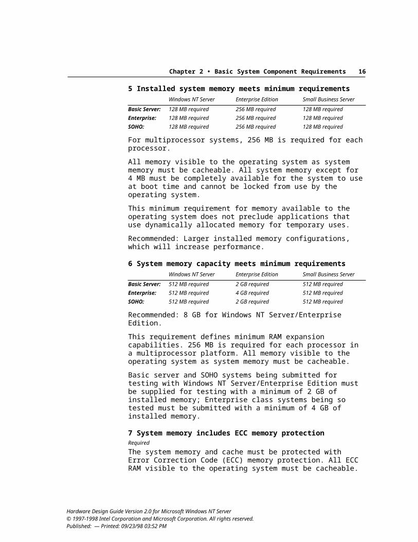
Chapter 2 • Basic System Component Requirements 21
Plug and Play RequirementsThis section defines the specific requirements for Plug and Play.
12 System and device configuration meet Plug and Play requirementsRequired
Optional: Support for legacy Plug and Play technology.
Windows NT Server 5.0 implements complete support for Plug and Play configuration. Each bus and device provided in a server system must meet the current Plug and Play specifications related to its class, including requirements defined in Section 6 of the ACPI 1.0 specification and the clarifications published for some Plug and Play specifications. This includes requirements for automatic device configuration, resource allocation, and dynamic disable capabilities.
For information about new Plug and Play support under Windows NT 5.0, see the Windows NT 5.0 DDK.
The following are current version numbers for all Plug and Play specifications:
PCI Local Bus Specification, Revision 2.1 Plug and Play External COM Device Specification, Version 1.0 Plug and Play Industry Standard Architecture (ISA) Specification, Version
1.0a, plus Clarification to Plug and Play ISA Specification, Version 1.0a Plug and Play Parallel Port Device Specification, Version 1.0b Plug and Play Small Computer System Interface Specification, Version 1.0 Universal Serial Bus Specification, Version 1.0
Note: Standard system devices are excluded from the Plug and Play requirement. The system can reserve static resources for devices such as programmable interrupt controllers (PICs) 1 and 2, timer (8254-2), keyboard controller (8042), real-time clock, DMA page registers, and DMA controllers 1 and 2. For systems based on Intel Architecture processors, these fixed resources are located at I/O addresses under 100h and can also include a Non-Maskable Interrupt (NMI).
Also, this requirement does not apply to devices that are completely invisible to the operating system, such as out-of-band systems management devices or I2O hidden devices; however, these devices still must properly reserve resources using ACPI methods to avoid potential conflicts.
13 Unique Plug and Play ID is provided for each system device and add-on deviceRequired
Each device connected to an expansion bus must be able to supply its own unique identifier, as defined in the current Plug and Play specification for the bus that it uses. The following defines the specific requirements for Plug and Play device IDs:
Hardware Design Guide Version 2.0 for Microsoft Windows NT Server© 1997-1998 Intel Corporation and Microsoft Corporation. All rights reserved. Published: — Printed: 09/23/98 03:52 PM
Chapter 2 • Basic System Component Requirements 22
Each separate function or device on the system board set must be separately enumerated. Therefore, each must provide a device identifier in the manner required for the bus it uses.
If a device on an expansion card is enumerated by the BIOS, it must have a unique ID and its own resources according to the device-ID requirements for the bus to which the card is connected. This includes devices that are separately enumerated on multifunction cards or multifunction chips.
The following are exceptions to the requirements for a unique Plug and Play ID:
Legacy devices attached to the ISA bus on the system board set do not have unique Plug and Play IDs—for example, serial ports, parallel ports, or PS/2-compatible port devices. The method for device identification is defined in Plug and Play ISA Specification, Version 1.0a, and the ACPI 1.0 specification.
Some multifunction devices (such as Super I/O) might include devices that do not have unique Plug and Play IDs or unique PCI Subsystem IDs, but that are supported by drivers provided with the Windows NT operating system.
A device such as a multifunction PCI device that supports a number of functions but uses only a single set of relocatable resources does not have to provide separate identifiers for each function included on the device.
Some devices are completely invisible to or are not managed by the operating system, such as out-of-band systems management devices or I2O system and I2O hidden devices. Such devices are exempt from this requirement, but these devices still must properly reserve resources using ACPI methods to avoid potential conflicts.
In addition, if an OEM uses a proprietary mechanism to assign asset or serial numbers to hardware, this information must be available to the operating system using Windows hardware instrumentation technology.
14 Option ROMs meet Plug and Play requirementsOptional
This feature does not apply for DEC Alpha servers. These recommendations apply whether the device is present on the system board set or is provided through an expansion card. Related option ROM recommendations are also defined later in this guide for specific bus classes and specific devices, such as SCSI and graphics adapters, respectively.
Option ROMs are usually located on cards used as system boot devices. During the boot process, option ROMs initialize the boot devices, which provide the primary input, primary output, and IPL device to boot the system. However, Plug and Play option ROMs can be used to supply the Plug and Play expansion header to devices other than boot devices, enabling them to initialize both devices when the system boots.
Hardware Design Guide Version 2.0 for Microsoft Windows NT Server© 1997-1998 Intel Corporation and Microsoft Corporation. All rights reserved. Published: — Printed: 09/23/98 03:52 PM
Chapter 2 • Basic System Component Requirements 23
To design an option ROM with Plug and Play capabilities, follow the require-ments described in the Plug and Play BIOS Specification, Version 1.0a, Clarification to Plug and Play BIOS Specification, Version 1.0a, and the Compaq, Intel, Phoenix BIOS Boot Specification, Version 1.01, which describe the Plug and Play expansion header and the interaction between the system BIOS and the option ROM.
15 “PNP” vendor code is used only to define a legacy device’s Compatible IDRequired
All legacy devices not enumerated by the system board set interface must not use “PNP” in their vendor and device codes. The PNP vendor code is reserved for Microsoft and vendors whose hardware is specifically assigned a particular ID. Other hardware can use a PNP code only when defining a device’s Compatible ID (CID) and only after first indicating the device’s Hardware ID in the Plug and Play header.
Use of CIDs is recommended for devices that use device drivers provided with the Windows NT operating system, such as a standard COM port (PNP0500).
Device Bay RequirementsDevice Bay is not required for servers in this version of this guideline. However, if a Device Bay-compatible bay is implemented in a server, it must comply with the requirements in this section.
Device Bay is one solution to the problem of “surprise removal” of devices, providing a mechanism that combines well-defined notification mechanisms between the hardware and software with a physical interlock mechanism to prevent removal of a device without the corresponding hardware or software notifications. Server vendors should use Device Bay or other mechanisms, such as captive cables or other physical restraint mechanisms, to prevent accidental or surprise removal of devices without notifying the operating system of the operation.
16 Device Bay controller and devices, if present, meet Device Bay 1.0 and other requirementsRequired
If implemented in a server, Device Bay capabilities must meet the following requirements:
The system includes a Device Bay Controller (DBC) that complies with Device Bay Interface Specification, Version 1.0 or later. If the DBC is implemented as a USB device, it must comply with Universal Serial Bus Device Class Definition Device Bay Controllers, Version 1.0 or later.
The system includes one USB port and one IEEE 1394 port for each Device Bay-capable bay in the system.
Hardware Design Guide Version 2.0 for Microsoft Windows NT Server© 1997-1998 Intel Corporation and Microsoft Corporation. All rights reserved. Published: — Printed: 09/23/98 03:52 PM
Chapter 2 • Basic System Component Requirements 24
Any Device Bay peripherals provided with a server must meet the following requirements:
Device complies with Device Bay Interface Specification, Version 1.0 or later.
Device uses either the USB bus, IEEE 1394 bus, or both. If the device uses the USB bus, it must also comply with the relevant USB
device class specifications.
Hardware Design Guide Version 2.0 for Microsoft Windows NT Server© 1997-1998 Intel Corporation and Microsoft Corporation. All rights reserved. Published: — Printed: 09/23/98 03:52 PM
25
C H A P T E R 3
This chapter defines specific requirements for buses and devices provided in a Basic server system.
Tips for selecting I/O performance components. For manufacturers who want to select high-performance components for server systems, the following are design features to look for in I/O components:
The system has minimal or no reliance on embedded ISA and no ISA slots. Adapter supports bus mastering. PCI adapter properly supports higher-level PCI commands for efficient data
transfer. Drivers are tuned for 32-bit performance: that is, 32-bit alignments on the
adapter do not interface with 16-bit alignments on odd addresses. All devices and controllers must be capable of being identified and
configured by software through the defined bus mechanisms.
I/O Bus RequirementsThis section summarizes requirements for the I/O bus, with emphasis on requirements related to the PCI bus.
17 System provides an I/O bus based on industry standard specificationRequired
Currently, for most systems, this requirement is met with PCI.
18 System supports a 32-bit bus architectureRequired
For example, for PCI, the server system must support the 32-bit physical address space; PCI adapters must be capable of addressing any location in that address space.
Hardware Design Guide Version 2.0 for Microsoft Windows NT Server © 1997-1998 Intel Corporation and Microsoft Corporation. All rights reserved. Published: — Printed: 09/23/98 03:52 PM
Bus and Device Requirements
0 Chapter 3 • Basic Bus and Device Requirements 261
19 System supports a 64-bit bus architectureWindows NT Server Enterprise Edition Small Business Server
Basic Server: Recommended Recommended OptionalEnterprise: Recommended Required OptionalSOHO: Recommended Recommended Optional
For example, the server system with a 64-bit PCI bus should support the 64-bit physical address space; 64-bit PCI adapters must be able to address any location in the address space supported by the platform.
For servers with 64-bit processors or running Windows NT Server/Enterprise Edition version 5.0 or later, the system must support a 64-bit PCI bus. Additionally, support for a 66-MHz PCI bus is recommended.
20 PCI bus and devices comply with PCI 2.1 and other requirementsRequired
Recommended: PCI controllers implemented as peer bridges to provide more effective bus bandwidth. Also, servers with more than 4 GB of memory should support the PCI dual address cycle (DAC) for the 64-bit physical address space. DAC support does not preclude hardware from using 32-bit addressing.
If PCI is present in the system, the PCI bus and PCI expansion connectors must meet the requirements defined in PCI Local Bus Specification, Revision 2.1 or later (PCI 2.1), plus any additional PCI requirements in this guide. It is recommended that PCI devices, chip sets, and expansion slots support the requirements defined in the PCI 2.2 specification. The system must also support the addition of PCI bridge cards, and all PCI connectors on the system board set must be able to allow any PCI expansion card to have bus master privileges.
All server systems also must meet the PCI requirements defined in this section, which include requirements to ensure effective Plug and Play support. In particular, see the required implementation for PCI 2.1 Subsystem Vendor IDs in requirement #30, “Device IDs include PCI Subsystem IDs.”
21 System makes a best effort to provide each PCI slot and device type access to a non-shared interrupt lineRequired
System designers must make a best effort to provide access to non-shared interrupt lines by meeting these conditions:
The system design enables all PCI slots and PCI device types to obtain exclusive use of an interrupt line when exclusive access increases performance.
Dedicated PCI interrupts must not use vectors from ISA bus interrupts.
The high-end and low-end commodity server platforms present certain design challenges. For high-end servers, PCI 2.1 taken by itself imposes a limitation for Intel Architecture-based systems because the values written to the Interrupt Line register in configuration space must correspond to IRQ numbers 0–15 of the
Hardware Design Guide Version 2.0 for Microsoft Windows NT Server© 1997-1998 Intel Corporation and Microsoft Corporation. All rights reserved. Published: — Printed: 09/23/98 03:52 PM
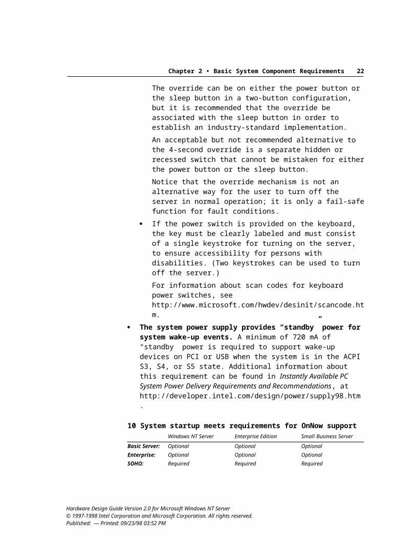
0 Chapter 3 • Basic Bus and Device Requirements 271
standard dual 8259 configuration, or to the value 255 which means “unknown” or “no connection.” The values between 15 and 255 are reserved. This fixed connection legacy dual 8259 configuration, if examined alone, constrains Intel Architecture-based systems, even when they use sophisticated interrupt-routing hardware and APIC support. For low-end servers, some core logic offerings provide little or no interrupt-routing support, and designers implement rotating access to interrupt resources using simple wire-OR techniques, such as those illustrated in the PCI 2.1 implementation note in section 2.2.6 of the PCI 2.1 specification.
Windows NT, with its support for both MPS 1.4 and ACPI, uses mechanisms beyond the legacy methods of routing all PCI interrupts through the legacy cascaded 8259 interrupt controllers to determine proper allocation and routing of PCI bus IRQs. This Windows NT capability allows use of interrupts beyond the 0–15 range permitted by the strict reading of the current PCI 2.1 specification language for Intel Architecture systems. System designers should include sufficient interrupt resources in their systems to provide at least one dedicated interrupt per PCI function for embedded devices and one interrupt per PCI INTA# – INTD# line on a PCI slot. This will become a requirement for all servers in a future version of this guideline.
When system designers cannot provide a non-shared interrupt line to a particular PCI device or slot because of the above situations, the server system’s documentation must explain clearly to the end user of the system how interrupt resources are allocated on the platform and which devices cannot avoid sharing interrupts. System designers may provide this documentation or information as they deem most appropriate for their product. Some possible mechanisms include:
Documenting slots according to the order in which cards should be inserted to prevent interrupt sharing for as long as possible
Providing information on interrupt routing and sharing via system setup programs
Some instances need additional clarification to fit within the context of this guideline. At the system designer’s discretion, PCI devices can share an interrupt line under the following conditions:
One system interrupt line can be shared by all PCI devices on an expansion card. In other words, PCI INTA# – INTD# may share the use of a single system interrupt directed to a given PCI expansion slot. This instance of line sharing applies to both expansion card designs based on PCI multifunction devices and to expansion card designs using PCI-to-PCI bridges.
Devices can share an interrupt in a design where a system-board set has multiple instances of a given PCI device performing a specific function. For example, two embedded PCI SCSI controllers on a system board can share a single system interrupt line. A single line can be shared when the functions of the devices are very similar, such as a case where one embedded SCSI
Hardware Design Guide Version 2.0 for Microsoft Windows NT Server© 1997-1998 Intel Corporation and Microsoft Corporation. All rights reserved. Published: — Printed: 09/23/98 03:52 PM
0 Chapter 3 • Basic Bus and Device Requirements 281
controller may be dedicated to “narrow” (8-bit wide) SCSI devices and the other is dedicated to “wide” (16-bit wide) SCSI devices. On the other hand, an embedded SCSI controller may not share an interrupt with an embedded network adapter on a system board, because they perform two different functions within the system and could contend for the shared interrupt in ways that will reduce overall system performance.
22 System does not contain ghost devicesRequired
A computer must not include any ghost devices, which are devices that do not correctly decode the Type 1/Type 0 indicator. Such a device will appear on multiple PCI buses.
A PCI card should be visible through hardware configuration access at only one bus/device/function coordinate.
23 System uses standard method to close BAR windows on nonsubtractive decode PCI bridgesRequired
PCI-to-PCI bridges must comply with the PCI to PCI Bridge Specification, Revision 1.0. Setting the base address register (BAR) to its maximum value and the limit register to zeroes must effectively close the I/O or memory window references in that bridge BAR.
24 PCI devices do not use the <1 MB BAR typeRequired
Recommended for Enterprise class servers: Devices on a 64-bit PCI bus must take any 64-bit BAR address.
Devices must take any 32-bit BAR address.
25 PCI devices decode only their own cyclesRequired
PCI devices must not decode cycles that are not their own to avoid contention on the PCI bus. Notice that this requirement does not in any way prohibit the standard interfaces provided for by the PCI cache support option discussed in PCI 2.1, which allows the use of a snooping cache coherency mechanism. Auxiliary hardware that is used to provide non-local console support is permitted within the scope of this requirement.
26 VGA-compatible devices do not use non-video I/O portsRequired
Recommended: Device includes a mode that does not require ISA VGA ports to function.
A VGA-compatible device must not use any legacy I/O ports that are not set aside for video in the PCI 2.1 specification.
Hardware Design Guide Version 2.0 for Microsoft Windows NT Server© 1997-1998 Intel Corporation and Microsoft Corporation. All rights reserved. Published: — Printed: 09/23/98 03:52 PM
0 Chapter 3 • Basic Bus and Device Requirements 291
27 PCI chip sets support Ultra DMA if primary host controller uses ATAWindows NT Server Enterprise Edition Small Business Server
Basic Server: Required Not applicable RequiredEnterprise: Required Not applicable RequiredSOHO: Required Not applicable Required
For servers that implement PCI ATA connectivity, PCI chip sets must implement DMA as defined in ATA/ATAPI-4 Revision 17 (ATA-4), and implement Ultra DMA (also known as Ultra-ATA) as defined in the ATA-4 specification.
Ultra DMA is required to avoid the bottleneck created by the current 16.6 MB per second limit on ATA disk transfer. Ultra DMA also provides error checking for improved robustness over previous ATA implementations.
An exemption exists for PCI ATA-connected CD drives used solely for the purpose of software installation on a server system. Such devices cannot be used for any other purpose, including access to data by client systems. This exemption will not be allowed in the next version of these guidelines.
This requirement does not apply for servers running Windows NT Server/Enterprise Edition, which do not use ATA for primary storage.
28 Functions in a multifunction PCI device do not share writable PCI Configuration Space bitsRequired
The operating system treats each function of a multifunction PCI device as an independent device. As such, there can be no sharing between functions of writable PCI Configuration Space bits (such as the Command register).
29 Devices use the PCI Configuration Space for their Plug and Play identifiersRequired
The PCI 2.1 specification describes the Configuration Space used by the system to identify and configure each device attached to the bus. The Configuration Space is made up of a 256-byte address space for each device and contains sufficient information for the system to identify the capabilities of the device. Configuration of the device is also controlled from this address space.
The Configuration Space is made up of a header region and a device-dependent region. Each Configuration Space must have a 64-byte header at offset 0. All the device registers that the device circuit uses for initialization, configuration, and catastrophic error handling must fit within the space between byte 64 and byte 255.
All other registers that the device uses during normal operation must be located in normal I/O or memory space. Unimplemented registers or reads to reserved registers must complete normally and return zero. Writes to reserved registers must complete normally, and the data must be discarded.
Hardware Design Guide Version 2.0 for Microsoft Windows NT Server© 1997-1998 Intel Corporation and Microsoft Corporation. All rights reserved. Published: — Printed: 09/23/98 03:52 PM
0 Chapter 3 • Basic Bus and Device Requirements 301
All registers required by the device at interrupt time must be in I/O or memory space.
30 Device IDs include PCI Subsystem IDsRequired
The Subsystem ID (SID) and Subsystem Vendor ID (SVID) fields are required to comply with the Subsystem ID ECN to PCI 2.1 or the equivalent requirement in PCI 2.2. The Subsystem ID ECN is available to PCI SIG members on the web at http://www.pcisig.com.
The device designer is responsible for ensuring that the SID and SVID registers are implemented. The adapter designer or system-board designer who uses this device is responsible for ensuring that these registers are loaded with valid non-zero values before the operating system accesses this device.
To be valid, the SVID must be provided by the PCI SIG. Values in the SID field are vendor-specific, but to be valid must be unique to
a subsystem configuration. For example, if two system boards have the same graphics chip set, but one supports an internal expansion connector while the other has added functionality such as a TV output function, then each must load the SID field with a different, unique value.
Valid non-zero values in the Subsystem ID fields are necessary for the correct enumeration of the device. When the Subsystem ID fields are populated correctly for the adapter, the operating system can differentiate between adapters based on the same PCI chip.
Valid non-zero values in the Subsystem ID fields also allow the operating system to load system miniports for system-board devices, and therefore Subsystem ID fields must also be populated on system-board devices. The exceptions to this requirement are PCI-to-PCI bridges, core chip sets, and OEM-unique system board set devices for system management that are not visible to the operating system. Notice that integration of features into core chipsets, such as graphics, audio, and so on, still requires that the unique feature integrated into a core chip set must meet this requirement.
The PCI specification and these guidelines require that all PCI functions ensure that the Subsystem ID fields are loaded with valid non-zero values before the operating system accesses the function’s Configuration Space registers. This is required both at initial operation system load and after any transition of the PCI bus from B3 (the unpowered state) back to B0 (the fully powered state).
For add-on cards, this requirement must be done by hardware on the card itself—for example, by way of serial EEPROM—and not by an extension BIOS or device driver. This is because the extension BIOS code or driver code is not guaranteed to run in all relevant cases, especially for system sleep transitions or dynamic bus power state transitions in which the bus becomes unpowered. Hardware methods to support this include:
Hardware Design Guide Version 2.0 for Microsoft Windows NT Server© 1997-1998 Intel Corporation and Microsoft Corporation. All rights reserved. Published: — Printed: 09/23/98 03:52 PM
0 Chapter 3 • Basic Bus and Device Requirements 311
Pin strapping at Reset Loading from an attached parallel or serial ROM
If a device is designed to be exclusively used on the system board, then the system-board vendor can load valid non-zero values into these registers using the system BIOS power-on self test (POST) code or ACPI control methods (_PS0 for PCI bus B3 to B0 transitions). This is because this code must always run before the operating system accesses a function’s Configuration Space registers. Once the operating system has control of the system, Subsystem IDs must not be directly writeable—that is, the read-only bit must be set and valid. See also the note on Subsystem Vendor IDs related to multiple-monitor support for display devices in requirement #13, “Unique Plug and Play ID is provided for each system device and add-on device.”
31 Configuration Space is correctly populatedRequired
Windows NT places extra constraints on a few configuration registers. Microsoft provides a program named Pci.exe to help debug the use of the Configuration Space. This program is available at http://www.microsoft.com/hwdev/pci/.
The following items are specific requirements for the Configuration Space:
Populate the class code register (09h) for all devices.Follow the base class, sub-class, and programming interface values outlined in PCI 2.1 or later.
Devices must not fill the BARs with random values.See PCI 2.1 or later for the correct usage of these registers. Notice that BARs (10h, 14h, 18h, 1Ch, 20h, and 24h) should return zero if they are not used, indicating that no memory or I/O space is needed.
Registers that have specific timing or latency requirements must not be placed in PCI Configuration Space.
32 Interrupt routing is supported using ACPIRequired
The system must provide interrupt routing information using a _PRT object, as defined in Section 6.2.3 of the ACPI 1.0 specification.
33 BIOS does not configure I/O systems to share PCI interruptsWindows NT Server Enterprise Edition Small Business Server
Basic Server: Recommended Required RecommendedEnterprise: Recommended Required RecommendedSOHO: Recommended Required Recommended
This applies to boot devices configured by the BIOS on systems that use Intel Architecture processors. The operating system should configure all other devices.
Hardware Design Guide Version 2.0 for Microsoft Windows NT Server© 1997-1998 Intel Corporation and Microsoft Corporation. All rights reserved. Published: — Printed: 09/23/98 03:52 PM
0 Chapter 3 • Basic Bus and Device Requirements 321
34 BIOS configures boot device IRQ and writes to the interrupt line registerRequired
This requirement does not apply for DEC Alpha servers. This requirement applies only to boot devices configured by the BIOS. All other devices should be configured by Windows NT because, after an interrupt request (IRQ) is assigned by the system BIOS, Windows NT cannot change the IRQ, even if necessary. If the BIOS assigns the IRQ and Windows needs it for another device, a sharing problem occurs.
The BIOS must configure the boot device IRQ to a PCI-based IRQ and write the IRQ into the interrupt line register 3Ch, even if the BIOS does not enable the device. This way, the operating system can still enable the device with the known IRQ at configuration time, if possible.
35 Systems that support hot swapping for any PCI device use ACPI-based methodsRequired
Windows NT 5.0 supports dynamic enumeration, installation, and removal of PCI devices only if there is a supported hardware insert/remove notification mechanism. The hardware insert/remove notification mechanism must be implemented as defined in Section 5.6.3 of the ACPI 1.0 specification.
36 All 66-MHz and 64-bit PCI buses in a server system comply with PCI 2.1 and other requirementsRequired
If PCI buses that are 66 MHz, 64 bit, or both are present in a server system, all devices connected to these buses must meet the requirements defined in PCI 2.1 or later.
It is recommended that 33-MHz/32-bit PCI devices and 66-MHz/64-bit PCI devices be placed on separate PCI buses to allow the best use of I/O bandwidth in a server system.
37 All PCI devices complete memory write transaction (as a target) within specified timesRequired
All devices must comply with the Maximum Completion Time ECN that is approved for the PCI 2.1 specification. This requirement is also documented in the PCI 2.2 specification. Complying with this requirement ensures shorter transaction latencies on PCI, allowing more robust handling of isochronous streams in the system.
38 All PCI components comply with PCI Bus Power Management Interface specification
Windows NT Server Enterprise Edition Small Business Server
Basic Server: Recommended Recommended RecommendedEnterprise: Recommended Recommended RecommendedSOHO: Required Required Required
Hardware Design Guide Version 2.0 for Microsoft Windows NT Server© 1997-1998 Intel Corporation and Microsoft Corporation. All rights reserved. Published: — Printed: 09/23/98 03:52 PM
0 Chapter 3 • Basic Bus and Device Requirements 331
The PCI bus, any PCI-to-PCI bridges on the bus, and all add-on capable devices on the PCI bus must comply with PCI Bus Power Management Interface Specification, Revision 1.1 or later. This includes correct implementation of the PCI Configuration Space registers used by power management operations, and the appropriate device state (Dx) definitions for the PCI bus, any PCI-to-PCI bridges on the bus, and all add-on-capable devices on the PCI bus. ACPI is not an acceptable alternative.
39 System provides support for 3.3Vaux if system supports S3 or S4 stateWindows NT Server Enterprise Edition Small Business Server
Basic Server: Recommended Recommended RecommendedEnterprise: Recommended Recommended RecommendedSOHO: Required Required Required
System support for delivery of 3.3Vaux to the PCI bus must be capable of powering a single PCI slot with 375 mA at 3.3V and it must also be capable of powering each of the other PCI slots on the segment with 20 mA at 3.3V whenever the PCI bus is in the B3 state.
Systems must be capable of delivering 375 mA at 3.3V to all PCI slots whenever the PCI bus is in any “bus powered” state: B0, B1, or B2.
40 PCI bus power states are correctly implementedWindows NT Server Enterprise Edition Small Business Server
Basic Server: Recommended Recommended RecommendedEnterprise: Recommended Recommended RecommendedSOHO: Required Required Required
The PCI bus must be in a bus state (Bx) no higher than the system sleeping state (Sx). This means that if the system enters S1, the bus must be in B1, B2, or B3. If the system enters S2, the bus must be in B2 or B3, and if the system enters S3, the bus must be in B3. Of course, in S4 and S5, the system power is removed, so the bus state is B3. A PCI bus segment must not transition to the B3 state until all downstream devices have transitioned to D3.
Control of a PCI bus segment’s power is managed using the originating bus bridge for that PCI bus segment.
For CPU-to-PCI bridges, these controls must be implemented using ACPI or the PCI Power Management Interface Specification, Revision 1.1 or later.
For PCI-to-PCI bridges, these controls must be implemented in compliance with the PCI Power Management Interface Specification, Revision 1.1. or later.
USB RequirementsThis section summarizes requirements for Universal Serial Bus. USB is not re-quired in a server system, but if present, it must comply with these requirements.
Hardware Design Guide Version 2.0 for Microsoft Windows NT Server© 1997-1998 Intel Corporation and Microsoft Corporation. All rights reserved. Published: — Printed: 09/23/98 03:52 PM
0 Chapter 3 • Basic Bus and Device Requirements 341
41 All USB hardware complies with USB 1.0 specificationsRequired
Recommended: USB hardware complies with Universal Serial Bus Specification, Version 1.1 or later.
All USB hardware present on a server system must comply with the Universal Serial Bus Specification, Version 1.0 or later
When a system has more than one host controller, each host controller must provide full bandwidth and isochronous support. Host controllers should be located on PCI to meet this requirement.
42 USB connections use USB iconRequired
The icon can be molded, printed, or affixed as a permanent sticker. Because the location and number of USB ports can vary, appropriate icons on both ports and cables are important for user ease-of-use. Therefore, USB icons are required for external cables, connecting cables, and connection ports.
Icons can be based on vendor designs, or vendors can use the recommended USB icon defined in Chapter 6 of the USB 1.1 specification as follows:
The USB icon should be molded into the connector and also placed on the product for ease of identifying the USB port. It is recommended that the icon on the product and the one on the plug be adjacent to each other when the plug and receptacle are mated. This icon can be used for both series A and B connector schemes. On the plug, there should be a 0.635-mm rectangular recessed area around the icon such that there is a perceptible feel of the icon.
43 USB devices and drivers support maximum flexibility of hardware interface optionsRequired
Device and driver designs should provide maximum flexibility of interface options to allow user-preference coordination by the operating system or other resource managers. This flexibility allows graceful use of multiple simultaneous devices and applications in a dynamic environment.
Specifically, devices and drivers:
Must provide multiple alternate settings for each interface where any alternate setting consumes isochronous bandwidth
Must not use isochronous bandwidth for alternate setting 0
Recommended: devices should consume bandwidth only when they are being used.
Hardware Design Guide Version 2.0 for Microsoft Windows NT Server© 1997-1998 Intel Corporation and Microsoft Corporation. All rights reserved. Published: — Printed: 09/23/98 03:52 PM
0 Chapter 3 • Basic Bus and Device Requirements 351
44 USB host controller complies with OpenHCI or UHCI specificationRequired
The host controller must comply with the specifications for either Open Host Controller Interface (OpenHCI; published by Compaq, Microsoft, and National Semiconductor) or Universal HCI (UHCI; published by Intel). Hardware manufacturers who design to one of these specifications are not required to provide an additional device driver for their host controller under the Windows NT operating system.
Multiple OpenHCI and UHCI USB controllers are supported concurrently by the operating system.
45 System and devices comply with USB power management requirementsRequired
The server system must comply with the power management requirements in the Universal Serial Bus Specification, Version 1.0 or later. In addition, USB devices must comply with the Interface Power Management feature in the USB Common Class Specification, Revision 1.0 or later.
46 USB devices comply with their related USB device class specificationsRequired
A USB peripheral that fits into one of the USB device class definitions must comply with the related USB device class specification. USB class drivers in the operating system are implemented to support compliant devices in each particular class. Class driver extensions and WDM allow IHVs to innovate and differentiate their products while still complying with class specifications in their base operational modes.
47 USB hubs comply with the USB Specification, Version 1.1Recommended
The Universal Serial Bus Specification, Version 1.1, defines requirements for USB hubs that cover some ambiguities in the original 1.0 specification.
48 Bus-powered USB hubs provide ports that can be individually power switchedRequired
To minimize USB power consumption requirements, bus-powered hubs must provide ports that can be individually power switched. This contributes to the goal of reducing overall system power consumption.
Hardware Design Guide Version 2.0 for Microsoft Windows NT Server© 1997-1998 Intel Corporation and Microsoft Corporation. All rights reserved. Published: — Printed: 09/23/98 03:52 PM
0 Chapter 3 • Basic Bus and Device Requirements 361
Other Bus RequirementsThis section summarizes requirements related to other buses.
49 Any subsystems implementing I2O comply with standards and other requirementsRequired
If I2O is implemented in a system, it must meet the requirements defined in this guide and in the I2O Architecture Specification, Version 1.5 or later, available from the I2O Special Interest Group (SIG) at http://www.i2osig.org.
If I2O is implemented on a system, the system BIOS must support I2O devices in the system in the following cases:
An I2O-capable system that includes no I2O-intelligent devices, whether provided on the system board set or as add-on devices. The system can have an installed adapter that is I2O-ready or I2O-compliant, and the BIOS must initialize the device as a multifunction device. The system cannot boot from this I2O device, because the BIOS does not support initialization of I2O bootable device.
An I2O-ready system that has some sort of intelligence on the system board set or on an add-on adapter that enables sending and receiving messages, as defined in the I2O specification. This intelligence can be an off-the-shelf processor, an application-specific integrated circuit (ASIC) when it is on the system board set, or it can be included as an add-on adapter. In these cases, the system BIOS must support initializing and configuring the device, including support for multifunction PCI. Initialization and configuration of a PCI device does not imply that the system BIOS supports compliant I2O initialization of boot devices or that the system can boot from an I2O device.
An I2O-compliant system that includes support for initializing and booting from I2O devices, whether provided on the system board set or as add-on devices. The system as a whole must be able to pass I2O compliance testing with Windows NT 5.0.
50 System does not include ISA expansion slotsRequired
No ISA expansion slots are allowed in servers designed to comply with these guidelines. The benefits of an ISA-free system include improved performance, easier and more stable system configuration, and lower support costs.
Out-of-band systems management devices that can be implemented in an ISA slot are the only case where an ISA slot can be present in a server. These exemptions provide a transition period for these specific technologies as they migrate to deterministic bus designs. It is anticipated that these exemptions will not be present in future versions of these guidelines.
Hardware Design Guide Version 2.0 for Microsoft Windows NT Server© 1997-1998 Intel Corporation and Microsoft Corporation. All rights reserved. Published: — Printed: 09/23/98 03:52 PM
0 Chapter 3 • Basic Bus and Device Requirements 371
51 System does not include embedded ISA network adapters, storage controllers, or graphics adaptersRequired
The benefits of an ISA-free system include improved performance, easier and more stable system configuration, and lower support costs.
52 System does not include ISA expansion devicesRequired
An ISA expansion device in this context is defined as being an expansion adapter or device installed in an ISA slot.
No ISA expansion devices are allowed, with specific exemptions for out-of-band systems management devices that can be implemented in an ISA slot; this is the only case where an ISA slot can be present in a server. These exemptions provide a transition period for these specific technologies as they migrate to deterministic bus designs. It is anticipated that these exemptions will not be present in future versions of these guidelines.
53 System includes APIC supportRequired
This requirement does not apply for DEC Alpha servers.
The server must include APIC support that complies with ACPI 1.0, implemented by including the Multiple APIC Description Table (ACPI Section 5.2.8). Features such as targeted interrupts, broadcast interrupts, and prior-owner interrupts must be supported. Intel Architecture processor implementations can use the Intel APIC component.
Implementation of APIC support on server systems provides a greater number of IRQ resources, even within traditional server architectures.
Device RequirementsThis section summarizes requirements for the system devices and peripherals provided with server systems.
Note: It is recognized that administrators might not want a keyboard, mouse, or monitor attached to working servers. However, these devices are typically required at least for installation of the operating system.
54 Device driver and installation meet Hardware Design Guide requirementsRequired
Each device must have drivers for the Windows NT operating system. The manufacturer does not need to supply a driver if the device passes compliance testing using a driver provided with the operating system.
If the manufacturer supplies drivers, the device drivers and installation requirements include the following:
Hardware Design Guide Version 2.0 for Microsoft Windows NT Server© 1997-1998 Intel Corporation and Microsoft Corporation. All rights reserved. Published: — Printed: 09/23/98 03:52 PM
0 Chapter 3 • Basic Bus and Device Requirements 381
All devices and drivers pass compliance testing for these guidelines. Each device included in a server system must comply with the requirements defined in this section and must have supporting 32-bit device drivers for the CPU platform and operating system. The installation and loading of a driver must not reduce or eliminate functionality of other devices installed on the system. The following are also required: Every driver (or minidriver) must support Plug and Play and power
management I/O request packets (IRPs). Real-mode or 16-bit protected-mode components must not be provided
to operate under Windows NT. Only 32-bit protected-mode components are installed on systems with 32-bit processors.
Any device with WDM-based operating system support must have a manufacturer-supplied WDM minidriver.
All devices in systems with 64-bit processors must have 64-bit Windows NT-compatible drivers.
All configuration settings are stored in the registry. The driver must not use INI files for configuration settings. The driver must also include correct provider, version, and copyright entries. This information is displayed in the user interface.
Files have correct identifiers and are stored in the correct locations. The correct minidriver or any other manufacturer-supplied files specified in the device’s INF must be installed in the correct location.For manufacturer-provided files, the vendor must not be identified as Microsoft; all other copyright and version information must be correct for the manufacturer.Driver files provided by the vendor must not use the same file names used by files included in Microsoft operating systems and provided as either retail or OEM products, unless specifically agreed upon with Microsoft.
Driver installation and removal use methods defined in the Windows NT DDK. The device driver must be removable using Windows-based software by using either the Windows Control Panel option for removing devices or its own remove utility. For information, see the Windows NT 5.0 DDK.However, any software applications included with the device can be installed using an alternate Windows-based installation method as defined in the Microsoft Platform SDK. Also, any software components and registry entries installed during driver installation must be removed during driver removal.
Driver supports unattended installation. It must be possible for a user to install a device’s driver without being present. This unattended installation can be done using a mechanism such as a script or special software for supplying the required parameters.
Windows Help file is provided if special driver parameters are used. This requirement ensures that the user can correctly change settings. The device’s
Hardware Design Guide Version 2.0 for Microsoft Windows NT Server© 1997-1998 Intel Corporation and Microsoft Corporation. All rights reserved. Published: — Printed: 09/23/98 03:52 PM
0 Chapter 3 • Basic Bus and Device Requirements 391
installation routine must install the Help file as part of the setup program. The user interface for the device’s dialog boxes must display the correct Help file; the Help file must contain relevant information to assist the user. The guidelines for implementing Help are defined in the Windows NT DDK.
55 Keyboard and mouse connections meet requirements for bus and device classesRequired
These requirements, which depend on the type of connection designed into the system, ensure that all Plug and Play requirements are met and that Microsoft drivers support this device.
If a PS/2-style keyboard port is used, the following requirements must be met:
Support PIC-based IRQ 1 on Intel Architecture systems, ensuring that software functions properly if it was written for legacy systems and expects to use this IRQ signal.
Map the I/O address ports to 60h and 64h. Return expected scan codes, including send ID (0F2h) and response ACK
(0FAh), plus 2-byte ID.
If a PS/2-style mouse port is used, the following requirements must be met:
Comply in full with requirements in the IBM Personal System/2 specifications.
Use a device with an 8042-compatible interface to the keyboard controller function to ensure compatibility with Windows NT. In most cases, the existing 8042 keyboard port is sufficient. The 8042 chip initiates a PIC-based IRQ 12 interrupt when the mouse is connected to the port.
Support PIC-based IRQ 12 to ensure the proper functioning of software written for legacy systems that use this IRQ signal.
Return expected codes, including send ID (0F2h) and response ACK (0FAh) + 1-byte ID.
If a USB connection is used, the following requirements must be met:
Meet requirements in Universal Serial Bus Specification, Version 1.0 or later. Meet requirements in USB Human Interface Device Class Specifications,
Version 1.0 or later. Implement minidriver support based on WDM HID class support in the
operating system, as defined in the Windows NT 5.0 DDK.
If a USB keyboard is the sole keyboard implementation in an Intel Architecture system, it must provide boot support as specified in “Startup Support Requirements” of Chapter 2, “System Component Requirements,” and as defined in Universal Serial Bus PC Legacy Compatibility Specification, Version 0.9 or
Hardware Design Guide Version 2.0 for Microsoft Windows NT Server© 1997-1998 Intel Corporation and Microsoft Corporation. All rights reserved. Published: — Printed: 09/23/98 03:52 PM
0 Chapter 3 • Basic Bus and Device Requirements 401
later. This support must provide the ability for the user to enter the system's BIOS setup program and provide enough functionality to get a USB-aware operating system installed and booted. On a DEC Alpha system, the keyboard must work as the input device using the ARC interfaces.
56 Serial port meets requirements for bus and device classesRequired
A serial port implementation that uses a non-legacy bus must meet the specific device class requirements for that bus. For example, a USB serial port implementation must comply with all related USB specifications, including:
Universal Serial Bus Specification, Version 1.0 or later. Universal Serial Bus Class Definition for Communication Devices,
Version 1.0 or later.The “Standard Serial Interface Circuit Emulation” appendix in the USB Class Definition for Communication Devices specifically addresses serial-port compatibility.
If a legacy serial port is implemented in a server system, it must meet the following requirements:
A 16550A buffered Universal Asynchronous Receiver/Transmitter (UART) or equivalent buffered legacy serial port is required to support high-speed communications while reducing the CPU requirements for servicing the device. The device must be able to support 115.2K baud.
A legacy serial port must provide flexible resource configuration and complete dynamic disable capabilities as defined in the Plug and Play External COM Device Specification, Version 1.0. The following are the recommended resource settings for non-PCI devices: Four I/O locations for each port (standard ISA I/O addresses are 3F8h,
2F8h, 3E8h, and 2E8h). Using the standard addresses ensures the proper functioning of software that directly addresses these locations.
Two IRQ signals (standard is PIC-based IRQ 3, IRQ 4). Support of the standard IRQ signals ensures the proper functioning of software written for systems that use standard IRQ signals.
Two IRQs are required for each port. If two serial ports are implemented in the system, the following IRQ assignments are recommended: For serial port A: selection between PIC-based IRQ 4 and IRQ 11. For serial port B: selection between PIC-based IRQ 3 and IRQ 10.
In the event of an irreconcilable conflict with other serial ports on the system, a legacy serial port must be capable of being disabled by Plug and Play software. This capability allows at least one of the two conflicting serial ports to operate correctly.
Hardware Design Guide Version 2.0 for Microsoft Windows NT Server© 1997-1998 Intel Corporation and Microsoft Corporation. All rights reserved. Published: — Printed: 09/23/98 03:52 PM
0 Chapter 3 • Basic Bus and Device Requirements 411
The BIOS must configure at least one serial port to use either 2F8h or 3F8h. This requirement allows the port to be treated as a boot device by the BIOS so that components can use the port for diagnostic purposes in the event that system debugging is required by either the BIOS or the operating system.
57 Parallel port meets requirements for bus and device classesRequired for all server types, with ECP support required for SOHO servers
In addition to other capabilities listed here, the parallel port on a SOHO system must support the ECP protocol as defined by the IEEE 1284-1994 specification. This capability allows connections with higher-speed parallel peripherals.
A parallel port implementation that uses USB must comply with all related USB specifications, including the USB core specification and any specific device class specification.
If implemented in a server system, a legacy parallel port must provide flexible resource configuration following the Plug and Play Parallel Port Device Specification, Version 1.0b. Resource requirements must be met for each device of this type on the system. The requirements cannot be split between two ports on the system.
For non-PCI devices, the minimum resource requirements for each parallel port on the system are as follows:
The parallel port must support ISA I/O addresses of 378h and 278h, plus 3BC or a vendor-assigned I/O address. Using these standard I/O addresses ensures proper functioning of software written for operating systems that directly address these locations.Recommended: Map the base I/O address to four additional locations.
The parallel port must support PIC-based IRQ 5 and IRQ 7. Using these standard IRQs ensures proper functioning of software written for operating systems that use standard IRQ signals.Recommended: Support five additional IRQ signals.
The parallel port must support two unique DMA channel selections if its design supports block data transfers to memory using DMA controllers. Notice also that the DMA function will not work on a parallel port without an IRQ because the end of a DMA transfer is signaled by an interrupt.
To ensure Plug and Play support for resolution of resource conflicts, a full list of options for all possible configuration combinations must be enumerated, including:
Options for both extended capabilities port (ECP) mode, which requires an I/O address, an IRQ, and a DMA selection, and standard LPT mode, which requires only an I/O address.
Options that specify only the I/O address, which allows Windows NT to assign the IRQ and DMA channel.
Hardware Design Guide Version 2.0 for Microsoft Windows NT Server© 1997-1998 Intel Corporation and Microsoft Corporation. All rights reserved. Published: — Printed: 09/23/98 03:52 PM
0 Chapter 3 • Basic Bus and Device Requirements 421
On Intel Architecture systems, Windows NT considers the parallel port base address stored in the first BIOS Data Area (BDA) locations to be LPT1. The address stored in the second location is LPT2, and so on. On DEC Alpha systems, the information is in the ARC tree. On all ACPI-based systems, the information is obtained through the ACPI tree.
A legacy parallel port implemented in a server system must also meet the following requirements:
Enhanced parallel port (EPP) support does not use restricted I/O addresses. Some EPP implementations require eight contiguous I/O ports. If EPP support is implemented, the hardware cannot use the ISA I/O address 3BCh as a base I/O address because VGA devices require use of port 3C0h.
Compatibility, nibble mode, and ECP protocols meet IEEE 1284-1994 specifications. Support for a parallel port must include the compatibility mode and nibble mode protocols required by the IEEE 1284-1994 specification for minimum compliance. This support allows other IEEE 1284-compliant devices to be connected without problems.Recommended: Port supports the ECP protocol as defined by IEEE 1284, allowing connections with higher-speed parallel peripherals. However, if the port can support the compatibility and nibble mode protocols as described earlier, it complies with the Basic and Enterprise class guidelines that allow connection of other IEEE 1284-compliant devices.
Port connectors meet the minimum requirements defined in the IEEE 1284-I specifications. IEEE 1284-I–compliant ports must use a standard DB25 connector found on existing system parallel port designs. This connector is called an IEEE 1284-A connector in the specification.IEEE 1284-II–compliant ports must use an IEEE 1284-C connector. This connector is used on both the port and the peripheral device.
IEEE 1284 peripherals have Plug and Play device IDs. The device ID is described fully in the IEEE 1284 specification. All characters in the device identification string must consist only of ASCII values 20h–7Fh. The device identification string consists of a leading zero, a hexadecimal value that represents the length of the string, and then a set of fields, in ASCII, with a unique identification string.In addition to the requirements specified in the Plug and Play Parallel Port Device Specification, Version 1.0b, the device ID string must contain the following keys, at a minimum. The keys are case sensitive and can be abbreviated in INF files as indicated.Required key Abbreviated string
MANUFACTURER MFGMODEL MDLCLASS CLSDESCRIPTION DES
Hardware Design Guide Version 2.0 for Microsoft Windows NT Server© 1997-1998 Intel Corporation and Microsoft Corporation. All rights reserved. Published: — Printed: 09/23/98 03:52 PM
0 Chapter 3 • Basic Bus and Device Requirements 431
All MANUFACTURER and MODEL key values must remain unique for each manufacturer. All MANUFACTURER, MODEL, CLASS, and DESCRIPTION key values must remain static for a specific unit; ID values do not change for different hardware configurations. For example, a user adding a memory module to a printer should not change the MODEL key value reported as part of the device identifier. However, if the user adds memory by installing an upgrade kit that requires a different driver or requires the existing driver to behave differently, then changing the MODEL value is acceptable as part of the upgrade installation process.The CLASS key describes the type of parallel device. The CLASS key can contain the values PRINTER, MODEM, NET, HDC, PCMCIA, MEDIA, FDC, PORTS, SCANNER, or DIGCAM. HDC refers to hard disk controller. MEDIA refers to any multimedia device. FDC refers to floppy disk controller.The DESCRIPTION key is an ASCII string of up to 128 characters that contains a description of the device that the manufacturer wants to have presented if a device driver is not found for the peripheral.For information about how the system determines the correct peripheral device driver, see the Windows NT DDK.Recommended: The CID key can provide a value that exactly matches a peripheral name supported by a device driver shipped with Windows NT Server. The value must match a value listed in the device’s INF file.
58 System includes emergency repair supportRequired
Floppy disk support is recommended for emergency-repair disk purposes; if an OEM does not provide a floppy disk drive for this purpose, an alternate emergency repair method must be provided.
If a floppy disk drive is provided, the recommended support should be a solution based on an external bus, supporting migration away from legacy devices. If implemented as an IDE floppy drive, the drive must comply with ANSI NCITS T10 Multi-Media Command Set-2 (MMC-2).
59 Primary graphics adapter meets minimum requirementsRequired
At a minimum, the adapter must support 800 × 600 × 256 color, following the VESA specification for this mode.
The adapter must also work normally with the default VGA mode driver, which is required for installing the operating system, so the primary adapter must support 4-bit planar VGA mode.
Hardware Design Guide Version 2.0 for Microsoft Windows NT Server© 1997-1998 Intel Corporation and Microsoft Corporation. All rights reserved. Published: — Printed: 09/23/98 03:52 PM
44
C H A P T E R 4
This chapter defines basic feature requirements for network adapters and other communications hardware. See also the related requirements for remote new system setup and service boot support using Dynamic Host Configuration Protocol (DHCP) and Trivial File Transfer Protocol (TFTP) as defined in “Manageability Requirements” of Chapter 7, “Reliability, Availability, and Serviceability Requirements.”
In this guide, all network communications devices are based on the same Network Driver Interface Specification (NDIS) 5.0 requirements, which includes requirements for power management and Plug and Play capabilities. NDIS 5.0 represents a number of extensions to the interface described in NDIS 3.0 and 4.0. The basic requirements, services, terminology, and architecture of these earlier versions also apply to NDIS 5.0. The new NDIS architecture is included in Windows NT 5.0 and is documented in the Windows NT 5.0 DDK. For additional background information about NDIS 5.0, see the web site at http://www.microsoft.com/hwdev/network/.
Note: References to adapters, network interfaces, and so on in this chapter should be taken to apply to add-on network adapter cards, network implementations on the system board, and external network interfaces equally and without preference for any of these types of implementation, unless otherwise noted.
Network Adapter RequirementsThis section describes the requirements for network adapters. Many of these requirements also apply to other network communications devices such as ISDN, cable modem, and ADSL. The section for each device category lists the applicable requirements for that device.
Hardware Design Guide Version 2.0 for Microsoft Windows NT Server © 1997-1998 Intel Corporation and Microsoft Corporation. All rights reserved. Published: — Printed: 09/23/98 03:52 PM
Networking and Communications Requirements
0 Chapter 4 • Basic Networking and Communications Requirements 451
Note: It is recognized that OEMs supply server systems to corporations in situations where the customer will insert network adapters at the end-user site. Systems designed for specific corporate customers are exempt from including a network adapter. However, if a network adapter is included in the system, it must meet these requirements.
Also, references in this chapter to adapters, network interfaces and so on should be taken to apply equally to add-in network adapter cards, network implemen-tations on the system motherboard, and external network interfaces, without preference for any of these types of implementation unless otherwise noted.
60 System includes non-ISA NDIS 5.0 network adapterRequired
An ISA-based network adapter solution is not allowed for a server system.
61 Network adapter uses NDIS 5.0 miniport driverRequired
The network adapter driver must be based on and comply with NDIS 5.0 in order to take advantage of new operating system capabilities. The driver must follow the NDIS miniport driver model defined in the Windows NT 5.0 DDK.
Important: The development of full MAC drivers is no longer supported. Support for full MAC drivers will be removed in the future versions of Windows.
If the network device is for connection-oriented media, such as Asynchronous Transfer Mode (ATM), ISDN, Frame Relay, or X.25, it must have a connection-oriented miniport driver that follows the connection-oriented model defined for NDIS 5.0 in the Windows NT 5.0 DDK. Also, for the connection-oriented media, there needs to be an NDIS 5.0 call manager driver as defined in the DDK.
In some cases, such as ATM, the call manager driver is included in the operating system and the vendor needs to provide only an NDIS 5.0 connection-oriented miniport driver. For other connection-oriented media, such as ISDN or X.25, the call manager is not included in the operating system and must be provided with the hardware. The call manager support can be integrated in the connection-oriented miniport driver or implemented as a separate NDIS 5.0 call manager driver. The documentation of both options, integrated or separated call manager, is included in the Windows NT 5.0 DDK.
An intermediate NDIS 5.0 miniport driver is required for network adapters that connect to the system using IEEE 1394 or USB buses. This driver exposes its media type to NDIS at its upper edge and interfaces with the appropriate bus driver, IEEE 1394 or USB, at its lower edge.
The NDIS 5.0 miniport driver must also meet these requirements:
Driver works correctly with Microsoft network clients and protocols. This includes the 32-bit Microsoft client and NetWare-compatible clients provided with Windows, whether connected to a Windows NT-based server,
Hardware Design Guide Version 2.0 for Microsoft Windows NT Server© 1997-1998 Intel Corporation and Microsoft Corporation. All rights reserved. Published: — Printed: 09/23/98 03:52 PM
0 Chapter 4 • Basic Networking and Communications Requirements 461
a Novell NetWare 3.x or 4.x server, or a Windows-based peer server. In all cases, this includes connections using Microsoft Transmission Control Protocol/ Internet Protocol (TCP/IP), IPX/SPX-compatible protocol, and NetBEUI in Local Area Networks. In Wide Area Networks, connections must work correctly using TCP/IP.
Driver makes only NDIS library calls or WDM system calls. NDIS conformance must be validated over single and multiple network connections. For Windows NT, this must be validated on a multiprocessor system as part of the testing process.
Driver uses new INF format. All network components must use the new style of INF format, which is based on the Windows 95 INF format. For information, see the Windows NT 5.0 DDK.For Windows NT 5.0, there will be no legacy INF support and no satisfactory upgrade option for OEM components created for Windows NT 4.0.
Driver is deserialized. NDIS 5.0 introduces support for deserialized miniports. This enables performance improvements and scalability on Windows NT multiprocessor systems.
62 NDIS 5.0 miniport driver supports high-performance send and receive callsRequired
NDIS drivers for server-side network adapters must support the new higher performance send (NdisSendPackets) and receive (NdisMIndicateReceivePacket) calls documented in the Windows NT 5.0 DDK.
63 Network adapter offloads TCP/IP checksum, IP Security encryption, and TCP message segmentation Recommended
Server-side network adapters should support task-offload mechanisms to offload TCP/IP checksum calculation, IP Security encryption, and TCP message segmentation to intelligent hardware. This provides better utilization of computing resources on the server system. Mechanisms for off-loading these tasks are documented in the Windows NT 5.0 DDK NDIS documentation.
64 Full-duplex adapter automatically detects and switches to full-duplex modeRequired
The network adapter must negotiate full duplex operation by default when both the network adapter and switch port in a link pair support full duplex and the networking technology provides a standard way for each to detect and/or negotiate the duplex mode. Half duplex may be used if that is the only mode supported by one or both link partners or if it can be manually configured when warranted by special conditions. The goal is to configure this setting automatically without end-user intervention.
Hardware Design Guide Version 2.0 for Microsoft Windows NT Server© 1997-1998 Intel Corporation and Microsoft Corporation. All rights reserved. Published: — Printed: 09/23/98 03:52 PM
0 Chapter 4 • Basic Networking and Communications Requirements 471
65 Adapter automatically senses presence of functional network connectionRequired
Where the network media allows it, the network adapter must be capable of dynamically determining whether it is connected to a functional link partner such as a hub, switch, or router. The device must indicate the link state in the following cases:
At boot time After returning to D0 power state When the link state changes while in the D0 power state (no time limit is
specified for the required detection or status indication)
If the adapter is on an expansion card not used as a boot device, then the device drivers can determine the presence of the functional link. If the device is not connected to a functional link partner, the miniport driver must provide appropriate NDIS status indication, using support for cable sense in NDIS 5.0.
For information about NDIS status codes and indication mechanisms, see the Windows NT 5.0 DDK.
66 Adapter automatically senses transceiver typeRequired
Network adapters that support multiple transceivers must be capable of automatically detecting which transceiver type is connected to the network unless this is not possible with the network media at hand. The network adapter then must automatically drive the correct connection. In all cases, the user must not be required to set jumpers or manually enter information to inform the operating system of the transceiver type.
67 Adapter can transmit packets from buffers aligned on any boundaryRequired
Buffer alignment refers to whether a buffer begins on an odd-byte, word, double word or other boundary. Adapters must be able to transmit packets any of whose fragments are on an odd-byte boundary.
For performance reasons, packets should be received into contiguous buffers on a double word boundary.
68 Adapter communicates with driver across any bridgeRequired
If the adapter uses a bridge, all communications must be free of errors across any bridge, such as a PCI bridge adapter.
69 Adapter supports filtering for at least 32 multicast addressesRequired
This recommendation applies to those networking technologies that support multicast, such as Ethernet, but it does not apply to those which do not, such as
Hardware Design Guide Version 2.0 for Microsoft Windows NT Server© 1997-1998 Intel Corporation and Microsoft Corporation. All rights reserved. Published: — Printed: 09/23/98 03:52 PM
0 Chapter 4 • Basic Networking and Communications Requirements 481
Token Ring. Token Ring for example, distributes IP multicast traffic using the functional address, as specified in RFC 1469.
This capability is needed to support new “push” technology applications such as Microsoft NetShow™, Active Desktop, and Internet Explorer 4.0. The minimum required capability is for filtering 32 multicast addresses (also known as channels).
70 Adapter supports configuration capabilities and registry settings for performance tuningRequired
Some network adapters and drivers might support additional configuration capabilities for performance tuning when used in special environments or applications. Any tuning parameters that are set by the user, an application, or the operating system must be controlled through registry variables.
An example of such performance optimizations might be adjustment of interrupt moderation or the number of receive buffers for systems used as dedicated routers.
In addition to Dynamic Interrupt Moderation, there are other techniques that may be implemented on network adapters to maximize system performance for special environments or applications.
User-tunable parameters must be set through registry variables as parameters for network adapters and must not be set in .INI files, configuration files, or in other locations. These parameters can be accessed using the Advanced Page in the Device Manager. The variables should be set through standard user interfaces provided in Windows.
71 Server network adapter supports remote system setup capabilitiesRecommended
It is strongly recommended that server network adapters support remote new system setup capabilities as defined in Network PC System Design Guide, Version 1.0b or later.
72 Network connections used for remote boot meet Net PC v.1.0b requirements for remote system setupRequired
On server systems that support remote new system setup, network connections used for remote boot must comply with remote new system setup capabilities as described in Network PC System Design Guide, Version 1.0b or later. It must be possible to enable and disable the remote boot (remote new system setup) capabilities through administrative control in order to maintain server security.
Note: Multiport network adapters can supply remote system setup capabilities on none, any, or all ports.
Hardware Design Guide Version 2.0 for Microsoft Windows NT Server© 1997-1998 Intel Corporation and Microsoft Corporation. All rights reserved. Published: — Printed: 09/23/98 03:52 PM
0 Chapter 4 • Basic Networking and Communications Requirements 491
73 PCI network adapter properly supports higher-level PCI commandsRequired
PCI commands are defined in the PCI 2.1 specification. This requirement ensures efficient data transfer.
74 Adapter and driver support promiscuous modeRequired
This ensures that the adapter can be used with Microsoft Network Monitor Agent. This requirement applies only to LAN (non-switched) media.
Notice that, by default, promiscuous mode is not turned on. Enabling promiscuous mode should be possible only by using the Microsoft Network Monitor Agent or another similar administrative application.
75 Adapter and driver support multicast promiscuous modeRequired
By supporting this feature, the adapter and the driver enable performance improvements for special-purpose servers and applications, such as multicast routers. This requirement applies to those networking technologies that support multicast, such as Ethernet, and not to those which do not, such as Token Ring.
Notice that, by default, multicast promiscuous mode is not turned on.
76 Network adapter and driver support priority for IEEE 802-style networksRecommended
Windows Quality of Service (QoS) components will provide link layer priority information to NDIS 5.0 miniport drivers in each transmitted packet’s NDIS_PER_PACKET_INFO structure. Priority values are derived by mapping IETF Integrated Services (intserv) service types to 802.1p priority values (referred to as the “user priority” object in http://search.ietf.org/internet-drafts/draft-ietf-issll-is802-svc-mapping-01.txt, which is likely to be superceded by a later draft or final specification). The intserv service type used for the mapping is determined by QoS-aware applications or on behalf of the application, by QoS-aware operating system components.
802.1p/q-capable Ethernet drivers are expected to use the priority level indicated in the NDIS_PER_PACKET_INFO structure to generate the corresponding field in the 802.1p/q MAC headers of transmitted packets. Similarly, these drivers are expected to extract the appropriate information from the MAC headers of received packets and to copy the priority to the NDIS_PER_PACKET_INFO structure before indicating the packet to higher protocol layers.
Note that any link layer driver may interpret the priority information in the NDIS_PER_PACKET_INFO structure and use it as appropriate for the particular media.
Hardware Design Guide Version 2.0 for Microsoft Windows NT Server© 1997-1998 Intel Corporation and Microsoft Corporation. All rights reserved. Published: — Printed: 09/23/98 03:52 PM
0 Chapter 4 • Basic Networking and Communications Requirements 501
For more information, see the Windows NT 5.0 DDK. See also the article “QoS: Assigning Priority in IEEE 802-style Networks,” available on the web at http://www.microsoft.com/devdes/qos802.htm.
77 Device Bay network adapter meets requirementsRequired
Any networking communications device designed as a Device Bay peripheral must interface with either USB, IEEE 1394, or both, and must support relevant USB device class specifications. All Device Bay peripherals must meet the requirements defined in Device Bay Interface Specification, Version 1.0 or later. See also requirement #16, “Device Bay controller and devices meet Device Bay 1.0 and other requirements.”
78 PCI network adapters are bus mastersRequired
To improve the system performance by decreasing the load on the system processor, the PCI network adapters must be bus masters.
79 USB or IEEE 1394 network device complies with related device class specificationsRecommended
USB network communications device vendors should implement forthcoming networking extensions to the USB Class Definitions for Communications Devices.
Vendors are also encouraged to participate in the definition and implementation of both USB and IEEE 1394 working group efforts.
80 Network device and driver meet Plug and Play and power management requirements.Required
The additional Plug and Play and power management requirements for network communications devices include the following:
Plug and Play capabilities support multiple adapters. For network communications devices, the Plug and Play IDs and resource support must be sufficient to automatically support the addition of multiple network communications devices to the system. This is true for the same and different types of network communications devices.
All resource settings are reported in the user interface. All resource settings must be viewable in the Device Manager and in adapter properties dialog boxes. All resource settings that can be changed by the user must be changed using the standard Windows user interface and not by way of INI files or other setting files.This implies that all device resources must be set and read through the device’s standard bus interfaces. For PCI devices, this interface is the PCI
Hardware Design Guide Version 2.0 for Microsoft Windows NT Server© 1997-1998 Intel Corporation and Microsoft Corporation. All rights reserved. Published: — Printed: 09/23/98 03:52 PM
0 Chapter 4 • Basic Networking and Communications Requirements 511
configuration space. Further, device parameter settings must be stored in the registry.
81 Network communications device supports wake-up eventsRecommended
This requirement applies specifically to the following network communications devices and their associated NDIS 5.0 miniport drivers:
Ethernet and Token Ring network adapters Integrated DOCSIS cable modems Other or future devices that transfer 802.3/DIX Ethernet framed packets
The Network Device Class Power Management Reference Specification, Version 1.0 or later, does not yet define wake-up mechanisms for ISDN adapters or any network communications adapter that uses ATM signaling.
The system must be capable of being awakened from a lower power state based on network events specified by the local networking software. This capability yields the result that any standard Windows network access—such as connections to shared drives and WinSock connections, plus service and management applications—can awaken a system from lower power states transparently.
As defined in Network Device Class Power Management Reference Specification, a network adapter and its driver must support wake-up on receipt of a network wake-up frame. Support for wake-up on detection of a change in the network link state or on receipt of a Magic Packet event is optional. Implementation details are described in the “Network Wake-up Frames” and “Network Wake-up Frame Details” sections of Network Device Class Power Management Reference Specification, Version 1.0a and in the Windows NT 5.0 DDK. See also the implementation notes at http://www.microsoft.com/hwdev/devdes/netpm.htm.
The packet patterns that define the wake-up frames are provided to the NDIS 5.0 miniport driver by the operating system. To enable Wake-On-LAN capability for basic networking scenarios, the network interface card must be capable of storing information describing a minimum of four wake-up packet patterns, and it must be able to recognize wake-up packets based on pattern matches anywhere in the first 128 bytes of the packet. The network adapters should be capable of storing information describing at least eight wake-up packet patterns to enable more advanced applications such as Wake-On-LAN capability on multi-homed systems or on receipt of multicast packets, in addition to the above basic scenarios.
PCI-based network adapters must support the generation of a power management event (PME# assertion) from the D3 cold device state if the physical layer technology is generally capable of operating under the voltage and current constraints of the D3 cold device state. For example, 100baseTX adapters can meet this requirement based on the state of the art in mid-1988. 1000baseSX or 1000base LX (gigabit Ethernet using optical fiber media) cannot meet this requirement because of the power required to operate the optical physical layer.
Hardware Design Guide Version 2.0 for Microsoft Windows NT Server© 1997-1998 Intel Corporation and Microsoft Corporation. All rights reserved. Published: — Printed: 09/23/98 03:52 PM
0 Chapter 4 • Basic Networking and Communications Requirements 521
Modem RequirementsThis section presents general requirements for modems.
There are two types of modems to consider.
Traditional modems, such as the type used in common PCs that are connected to the server system by a serial port, or a driver that emulates one.
Network modems, designed for large servers, that are connected to the server system by networking drivers, for example, NDIS 5.0 miniports.
Serial modems. The fundamental design principle for compatibility with Windows NT is for a serial modem to be supported by the Universal Modem Driver (Unimodem), which uses INF files to characterize device operation. Unimodem INF design is described in the Modem Developer’s Kit, http://www.microsoft.com/hwdev/modem/.
Networking modems. The fundamental design principle for compatibility with Windows NT is for a networking modem to be supported by NDIS 5.0, as defined in the Windows NT 5.0 DDK.
Note: It is recognized that OEMs supply systems to corporations in situations where the customer will insert modem devices at the end-user site or where the customer has particular feature demands. Server systems designed for specific corporate customers are exempt from these requirements.
Server Types and Modem UsageThis guide addresses Basic servers, SOHO servers, and Enterprise servers.
SOHO servers typically have a small number of serial modems, used for Remote Access (in or out), shared ISP access, FAX (in or out) and interactive voice response (IVR). The modems used are traditional serial modems, similar to those used for Workstation PCs, as defined in PC 98 System Design Guide or later. These modems are typically connected by individual PSTN phone lines or by ISDN BRI lines.
In an enterprise, the modem servers may support hundreds of modems, used primarily for inbound remote data access such as for an ISP or corporate network. The modems are typically connected to public networks on high speed digital lines (T1, ISDN, or PRI). Different servers may be used for dedicated incoming Fax reception or IVR. Note that Windows NT 5.0 Unimodem and TAPI can be used to support hundreds of modems for each server.
Hardware Design Guide Version 2.0 for Microsoft Windows NT Server© 1997-1998 Intel Corporation and Microsoft Corporation. All rights reserved. Published: — Printed: 09/23/98 03:52 PM
0 Chapter 4 • Basic Networking and Communications Requirements 531
Design Issues for Server ModemsFor modems designed for Basic servers, the most important additional design issues are:
Support for V.90, as host side modems where possible, which requires an ISDN or other digital network connection.
Support synchronous PPP, using V.8bis and V.80. Do not migrate the modem signaling function, for example, V.90 or V.34,
into the system.
For SOHO Server modems, the most important design issues are:
SOHO Server modems must support adaptive answering features: V.8, V.8bis, V.251.
Full duplex voice strongly recommended, using V.253, to support small scale Interactive Voice Response.
For Enterprise Server modems, the most important design issues are:
The NDIS 5.0 miniport interface is preferred. Fax is optional, not mandatory, because the most common solutions use
separate hardware and drivers, on separate public network connections.
82 System includes modem communications deviceRecommended
The following device options, as defined later in this chapter, can meet this requirement:
Serial modem with V.34 and V.90 56K ITU capabilities, supporting server fax capabilities (two or more ports recommended)
ISDN adapter ATM adapter ADSL adapter
83 Modem supports ITU-T V.250, Hayes-compatible command setRequired
ITU V.250 (formerly V.25 ter) is a superset of TIA-602. TIA-602 codifies the most common data modem commands and responses.
V.250 also includes two additional components:
A standard format for extending the AT command set, with standard means for the system to test the range of supported values for each command. This format enables adaptive modem installation.
Hardware Design Guide Version 2.0 for Microsoft Windows NT Server© 1997-1998 Intel Corporation and Microsoft Corporation. All rights reserved. Published: — Printed: 09/23/98 03:52 PM
0 Chapter 4 • Basic Networking and Communications Requirements 541
Standard extensions for modem ID, port control, modulation control and reporting, error control, and data compression control and reporting. Use of these extensions can reduce or eliminate the need for data modem INF files.
The essential V.250 commands are the following:
All basic modem commands from TIA-602 Identification: +GMI, +GMM, +GMR Port control: +IPR, +ICF, +IFC, +Ilrr Modulation: +MS, +MR, +MA Error control: +ES, +ER, +EB, +ESR, +ETBM Data compression: +DS, +DR
The particular utility of the standard format is that it allows a future modem installer to adaptively install and use a modem with minimal need for INF minidrivers.
84 Data modem supports PCM (V.90) with V.42 and V.42bis protocolRequired
This is the minimum modem capability specified in this guide.
85 Data modem supports digital connection to support host-side V.90 operation
Windows NT Server Enterprise Edition Small Business Server
Basic Server: Recommended Required RecommendedEnterprise: Required Required RequiredSOHO: Recommended Required Recommended
V.90 depends on a digital connection for the host-side modem to the public telephone network, typically using T1 or ISDN. Server modems should be designed for digital connection, to support host side V.90, where digital connections are available.
86 Fax modem supports 14.4 Kbps (V.17) with Class 1 (TIA-578-A) command setRequired
The following are recommended:
Class 1.0 (ITU T.31) with +FAR support, which allows the hardware to perform adaptive carrier detection
Class 2.0 (ITU T.32 or TIA-592) for server modems, which offloads the T.30 session protocol to the modem
Hardware Design Guide Version 2.0 for Microsoft Windows NT Server© 1997-1998 Intel Corporation and Microsoft Corporation. All rights reserved. Published: — Printed: 09/23/98 03:52 PM
0 Chapter 4 • Basic Networking and Communications Requirements 551
87 Fax modem supports adaptive DATA/FAX call classification based on T.32 +FAARequired
The adaptive DATA/FAX call classification must be based on the Class 2.0 +FAA command or equivalent proprietary +FAE command. This allows a server to handle remote access calls and inbound FAX calls on the same lines.
Windows NT 5.0 and future versions of Microsoft BackOffice® products will support Class 1.0 and Class 2.0 fax modems, and use adaptive call-classification support. To benefit from this support, modem vendors should extend their modem INFs to support the new registry keys needed to support these features, as defined in the MDK.
88 Data modem supports V.80 for synchronous accessRequired
This standard provides a control plane for the modem and synchronous access to the data path—the foundation for third-party voice/data/video software, for example, H.324 and V.70. Modems that support V.80 must also include V.8bis signaling and V.251 as described in requirement #85, “Modem supports adaptive connection, V.25, V.8, and V.8bis call control signaling with V.251 modem commands.”
89 Modem supports adaptive connection, V.25, V.8, and V.8bis call control signaling with V.251 modem commandsRequired
V.25 defines basic call-type selection, with an answer tone, a fax-calling tone, and a data-calling tone. V.8 defines advanced call-type selection, with complex information exchanged between terminals; V.8 is used in V.34, V.90, and some digital simultaneous voice/data (DSVD) implementations. V.8bis is required for standard multimedia modes, such as V.61 ASVD, V.70 DSVD, and H.324 video telephony, and to negotiate point-to-point synchronous PPP, supporting H.323.
V.251 enables the computer to participate in call control, allowing flexibility and a visual user interface, as well as saving modem complexity. V.251 requires DCE-controlled operation; in addition, DTE-controlled operation is recommended.
90 Modem supports blacklisted and delayed number clearingRequired where applicable
During certain international Post, Telephone, and Telegraph (PTT) certification processes, modems must support the blacklisted and delayed numbers feature. That means that when the modem fails to connect to a specific number for a certain number of times, the dialed number is stored in an internal list. Any subsequent automated dialing operation to this number is then either delayed for a time (delayed) or forbidden until some form of manual intervention occurs (blacklisted). The international certification processes specify that manual intervention using an external device is required in order to clear these numbers.
Hardware Design Guide Version 2.0 for Microsoft Windows NT Server© 1997-1998 Intel Corporation and Microsoft Corporation. All rights reserved. Published: — Printed: 09/23/98 03:52 PM
0 Chapter 4 • Basic Networking and Communications Requirements 561
The modem should clear its blacklisted and delayed number tables if the associated handset goes off hook.
91 Modem supports TDD, meeting V.18-1996 with V.250 AT commandsRecommended
People with deafness or reduced hearing can use Telephone Device for the Deaf (TDD), also known as Text Telephones, to communicate over phone lines. The U.S. Americans with Disabilities Act (ADA) requires all businesses of a certain size or larger to have Text Telephone services available and to be able to receive calls from people using Text Telephones.
In North America and Europe, the following types of Text Telephones are used:
Baudot: 45 or 50 bps Frequency-Shift-Keyed (FSK) and 5-bit Baudot coding ASCII: 300 bps Bell 103 and 7-bit ASCII coding European Deaf Telephone (EDT): 110 bps half-duplex V.21 and 7-bit coding Minitel: V.23 modems and 7-bit coding Modems and 7-bit coding DTMF: 2-digit or 3-digit character coding
The International Telecommunications Union (ITU) recommendation V.18 codifies how all these devices work and how to adaptively connect to all of them. ITU recommendation V.25ter contains AT commands for control of V.18 features in a modem.
Text Telephone capability should be included for the type of modem commonly used in the country of sale and use, for example, Baudot in the United States, Minitel in France, and so on.
92 Modem controller meets minimum requirementsRequired
The following are minimum requirements for the modem controller, in addition to supporting V.250:
Unimodem Diagnostics command, AT#UD Software-upgradable modem controller (upgradable ROM or
Windows modem) AT command buffer of at least 60 characters Semicolon (;) character dial string modifier, unless prohibited by national
regulations
Hardware Design Guide Version 2.0 for Microsoft Windows NT Server© 1997-1998 Intel Corporation and Microsoft Corporation. All rights reserved. Published: — Printed: 09/23/98 03:52 PM
0 Chapter 4 • Basic Networking and Communications Requirements 571
93 Voice modem support is providedWindows NT Server Enterprise Edition Small Business Server
Basic Server: Optional Optional OptionalEnterprise: Optional Optional OptionalSOHO: Recommended Recommended Recommended
Voice capability is recommended for SOHO server modems to support Interactive Voice Response and 3-way DATA/FAX/Voice call classification on the same phone lines. This support, if implemented, must meet the requirements documented in requirement #94, “Voice modem supports ITU V.253 (AT+V).”
94 Voice modem supports ITU V.253 (AT+V)Required
TIA IS-101-1994, the Interim Standard for Voice DCE, has been superseded by TIA-695 and ITU V.253-1998.
Voice capability is not mandatory, but if support for voice modem is implemented in a server system, it must meet the following requirements:
V.253 compliance Voice recording and playback (+VTX, +VRX) DTMF generation and detection during voice I/O Voice I/O support of 8-bit, 8-kHz PCM formats: unsigned linear, G.711
(A-law and u-law) Programmable gain control for all audio channels Speakerphone with automatic training (no user intervention) Voice I/O to the handset (for voice-only devices) Duplex voice, to support IP telephony and IVR Caller ID Detection and Reporting (+VCID)
ATM RequirementsThis section summarizes requirements for ATM hardware.
The NDIS 5.0 extensions provide kernel-mode NDIS 5.0 client drivers with direct access to connection-oriented media such as ATM. The new architecture for Windows NT extends native ATM support to Windows Sockets 2.0 (WinSock), Telephony API (TAPI), and applications based on Microsoft DirectShow™ by providing system-level components that map the applicable WinSock, TAPI, and DirectShow APIs to NDIS 5.0, extending direct ATM access to user-mode applications.
Hardware Design Guide Version 2.0 for Microsoft Windows NT Server© 1997-1998 Intel Corporation and Microsoft Corporation. All rights reserved. Published: — Printed: 09/23/98 03:52 PM
0 Chapter 4 • Basic Networking and Communications Requirements 581
ATM is not required for any of the server classes. If an ATM adapter is designed for operation under Windows NT in the server system, it must meet the requirements defined in this section. For more details about the following requirements, see “ATM Layer Specification” in ATM User-Network Interface Specification, Version 3.1. This specification also includes references to other relevant specifications.
95 ATM adapter meets network adapter requirementsRequired
The following network device requirements must be met:
#61, Adapter uses NDIS 5.0 [connection-oriented] miniport driver #65, Adapter automatically senses presence of functional network connection #67, Adapter can transmit packets from buffers aligned on any boundary #68, Adapter communicates with driver across any bridge #77, Device Bay network adapter meets requirements #78, PCI network adapters are bus masters #79, USB or IEEE 1394 network device complies with related device class
specifications
96 ATM adapter supports a minimum number of simultaneous connectionsRequired
The VPI (Virtual Path Identifier) and VCI (Virtual Channel Identifier) ranges supported by the adapter affect the maximum number of simultaneous connections supported on a system.
This affects the applicability of the adapter to ATM applications such as LAN Emulation, where at least one dedicated virtual channel is created between each pair of communicating ATM hosts.
System type Simultaneous connections
Client (ATM adapter) 64 or moreClient (Integrated ATM/ADSL-adapter) 16 or moreServer 2048 or more
A sample driver is provided in the Windows NT DDK to guide developers in properly supporting resources to meet this requirement.
Hardware Design Guide Version 2.0 for Microsoft Windows NT Server© 1997-1998 Intel Corporation and Microsoft Corporation. All rights reserved. Published: — Printed: 09/23/98 03:52 PM
0 Chapter 4 • Basic Networking and Communications Requirements 591
97 ATM adapter supports all service types defined by the ATM ForumWindows NT Server Enterprise Edition Small Business Server
Basic Server: Recommended Required RecommendedEnterprise: Recommended Required RecommendedSOHO: Recommended Required Recommended
The ATM adapter should support the constant bit rate (CBR), variable bit rate (VBR), available bit rate (ABR), and unspecified bit rate (UBR) service types as defined by the ATM Forum.
98 ATM adapter supports UBR service typeRequired
UBR is used by default for standard ATM services such as LAN Emulation and IP over ATM. In addition, PPP is a widely used model for residential network access and UBR is used by default for PPP over ATM virtual circuits. Therefore, it is required that ATM adapters support the UBR service type.
99 ATM adapter supports a minimum number of simultaneously active VBR or CBR connectionsRequired
Support for at least two simultaneously active VBR or CBR connections is required for basic ATM signaling and management.
Support for additional VBR/CBR connections is needed for ATM adapters that support multimedia or other traffic that demands Quality of Service (QoS). These are listed in the following table.
System type Simultaneous active VBR/CBR connections
Client 6Server 500
100 ATM adapter supports traffic shapingRequired
The ATM adapter must support and enforce all the traffic-shaping rules specified for each service type it supports, including CBR, VBR, ABR, and UBR.
Note: This includes enforcement of peak cell rate on UBR virtual circuits.
101 ATM adapter enforces PCR on UBR virtual circuitsRequired
ATM adapters will be used to connect router, remote access, and content servers to the public ATM network. High-speed residential broadband access networks such as ADSL and cable modem will use an ATM virtual circuit from home or small office computers to connect directly to these servers. When the Windows Dial-Up Networking UI is used to connect from a home or small business computer to a remote router or server, a PPP link is established over an ATM virtual circuit.
Hardware Design Guide Version 2.0 for Microsoft Windows NT Server© 1997-1998 Intel Corporation and Microsoft Corporation. All rights reserved. Published: — Printed: 09/23/98 03:52 PM
0 Chapter 4 • Basic Networking and Communications Requirements 601
The service type used on this PPP over ATM virtual circuit is unspecified bit rate (UBR). When creating the UBR virtual circuit, Windows will request upstream and downstream line rates, or Peak Cell Rates (PCR), equal to the upstream and downstream line rates provisioned for the user. Windows uses the ATM Interim Local Management Interface (ILMI) protocol to obtain information, such as getting the user’s provisioned line rates from the public network.
To avoid packet loss and ensure efficient network utilization, it is critical that all ATM, integrated ATM/ADSL adapters, or ATM/cable modem adapters enforce requested PCR on UBR virtual circuits.
Because any ATM adapter might be installed in a server to which clients connect through the public network, this requirement applies to all ATM adapters.
102 ATM adapter and driver support dynamic link speed configurationRequired
When connected to a residential broadband network, ATM adapters must restrict the aggregate transmission rate across all active virtual circuits so that it does not exceed the provisioned upstream bandwidth of the residential broadband network.
All integrated ATM/ADSL and ATM/cable modem adapters must support aggregate shaping of upstream bandwidth according to the provisioned upstream bandwidth or the trained bandwidth, whichever is lower. Some implementations can support rate adaptation, and lower than provisioned rates may be negotiated due to poor line conditions. All 25-Mbps ATM adapters must support this as well, because any 25-Mbps ATM adapter could be used to connect by way of an external ADSL modem to an ADSL network. This support is optional for ATM adapters with line rates higher than 25 Mbps.
The Windows ATM Call Manager uses ILMI to query the public network to discover the provisioned maximum line rates for incoming and outgoing traffic. The Call Manager then uses the OID_GEN_CO_LINK_SPEED NDIS request (in SET mode) to set the line rate for both incoming and outgoing traffic. The adapter must shape the aggregate of ATM traffic within these incoming and outgoing rates.
103 ATM adapter supports OAMRequired
Operation and maintenance (OAM) is needed for diagnostics. This capability is required for a server system. At minimum, the ATM adapter must respond to received F4 and F5 loopback OAM cells. Support for other layers, F1–F3 is optional.
104 ATM adapter supports buffer chaining (Tx + Rx)Required
This feature is needed for large packets. This capability is required for server systems, but is recommended for client systems.
Hardware Design Guide Version 2.0 for Microsoft Windows NT Server© 1997-1998 Intel Corporation and Microsoft Corporation. All rights reserved. Published: — Printed: 09/23/98 03:52 PM
0 Chapter 4 • Basic Networking and Communications Requirements 611
ADSL RequirementsThis section summarizes requirements for ADSL hardware.
Support is provided in the Windows NT Server operating system for ADSL adapters and external ADSL modems, such as those using USB, which provide a faster method for moving data over regular phone lines. ADSL adapters are not required for any server type, but if an adapter is included in a server, it must meet the requirements in this section. ADSL is not required in a server system, but if present, it must comply with these requirements.
Please review the white paper, An Interoperable End-to-End Broadband Service Architecture over ADSL Systems Version 3.0, which discusses end-to-end service interoperability over ADSL. This paper, which is available from the web site at http://www.microsoft.com/hwdev/publicnet/, was jointly developed by over 30 leading ADSL vendors. The core idea of this white paper (PPP over ATM over ADSL) has been adopted by the ADSL Forum.
105 ADSL device is implemented as an integrated ADSL modemRecommended
System designers should integrate the ADSL modem and higher layer transmission and media access functions on a single network device. A typical implementation integrates an ADSL modem and ATM interface on a single PCI network adapter. Another example is a device that connects to the server using the USB or IEEE 1394 bus.
If external ADSL modems are provided (other than IEEE 1394 or USB), it should have an ATM interface for the ADSL modem to server connection. In addition, an Ethernet interface can also be included.
106 Integrated ADSL modem meets network adapter requirementsRequired
For the integrated ADSL modem, the following network adapter requirements must be met:
#65, Adapter automatically senses presence of functional network connection #67, Adapter can transmit packets from buffers aligned on any boundary #68, Adapter communicates with driver across any bridge #77, Device Bay network adapter meets requirements #78, PCI network adapters are bus masters #79, USB or IEEE 1394 network device complies with related device class
specifications
Hardware Design Guide Version 2.0 for Microsoft Windows NT Server© 1997-1998 Intel Corporation and Microsoft Corporation. All rights reserved. Published: — Printed: 09/23/98 03:52 PM
0 Chapter 4 • Basic Networking and Communications Requirements 621
For the integrated ADSL modem exposing an ATM interface, the following requirements must be met as defined in “Network Adapter Requirements” earlier in this chapter:
#61, Adapter uses NDIS 5.0 [connection-oriented] miniport driver
For the integrated ADSL modem exposing an Ethernet interface, the following requirements must be met as defined in “Network Adapter Requirements” earlier in this chapter:
#61, Adapter uses NDIS 5.0 miniport driver #69, Adapter supports filtering for at least 32 multicast addresses #74, Adapter and driver support promiscuous mode
107 ATM/ADSL solution is implemented for integrated ADSL modemsRecommended
An integrated ADSL modem should expose ATM to the operating system. For ATM-specific requirements when an ATM/ADSL solution is implemented, see the requirements in “ATM Adapter Requirements” earlier in this chapter. This should comply with the PPP over ATM architecture discussed earlier.
Note: ATM/ADSL is a requirement for UADSL implementations. Currently there are both ATM/ADSL and Ethernet/ADSL based implementations to provide full rate ADSL services in the market. For compatibility with the Universal ADSL based services that will be rolled out within the next couple of years, PPP/ATM/ADSL is the required implementation.
108 ADSL modem supports DMT line encodingRecommended
The ADSL modem must support DMT line encoding, which is recognized as the industry standard for ADSL by ANSI as the T1.413 Issue 2 specification and also by the Universal ADSL Working Group. For information, see the web site at http://www.uawg.org.
Note: DMT is a requirement for UADSL implementations. The UAWG has adopted DMT specified by T1.413, with modifications being made to work in a splitterless environment.
109 ADSL modem supports rate adaptationRecommended
On a rate adaptive digital subscriber line (RA-ADSL), the downstream and upstream data rates are independently set either by an automatic adaptive algorithm or by manual selection.
RA-ADSL provides the capability to optimize the transmission speed and per-formance over a wide range of telephone-line loop distances. Adaptive channel equalization ensures more robust performance in the presence of channel impairments and narrow-band interference.
Hardware Design Guide Version 2.0 for Microsoft Windows NT Server© 1997-1998 Intel Corporation and Microsoft Corporation. All rights reserved. Published: — Printed: 09/23/98 03:52 PM
0 Chapter 4 • Basic Networking and Communications Requirements 631
This also helps telephone companies to provision RA-ADSL access on their existing networks. RA-ADSL products can be provisioned on many telephone lines without costly and time-consuming network upgrades.
Cable Modem RequirementsCable modems are not required on servers. If they are implemented, they must meet the requirements in this section.
Cable modem provides two-way services: Data flows downstream from the cable operator’s head end and upstream from the customer’s PC. At the head end, the cable data system is terminated by the cable modem termination system (CMTS), which terminates the upstream and downstream radio frequency (RF), MAC layer, and possibly Layer 3 protocols from the cable side. CMTS provides the internetwork connection between the cable system and the rest of the network at the head end. CMTS can be implemented on a proprietary hardware platform or a PC platform running Windows NT to provide different networking functions such as routing, Quality of Service (QoS) support (such as RSVP), and so on.
Some implementations transmit upstream using narrow-band networks such as ISDN or analog modem, but as cable companies upgrade their networks, an increasing number of RF return modems, for example, two-way modems, are being deployed. Two-way modems are preferred, because they are always connected, perform better, and do not tie up phone lines or require modem banks.
The three current cable modem specifications are:
Data-Over-Cable Service Interface Specification (DOCSIS), developed by the Multimedia Cable Network System (MCNS) consortium.
IEEE 802.14, developed by IEEE. Digital Video Broadcasting/Digital Audio-Visual Council (DVB/DAVIC),
developed by DAVIC and DVB and adopted by European Telecommunication Standards Institute (ETSI) and International Telecommunication Union (ITU).
Industry support for DOCSIS is growing rapidly in North America. In present form, its upper layers fully describe IP traffic encapsulated by 802.3/DIX Ethernet framing. ATM is left for future study.
External Ethernet DOCSIS cable modems provide IEEE 802.1d bridging for one or more Customer Premises Equipment (CPE); a PC attaches to them indirectly through its 10BASE-T network adapter. Integrated cable modems attach directly to the PC over buses such as USB, PCI, and IEEE 1394, and require a vendor-supplied NDIS 5.0 miniport driver. This driver exposes an 802.3/DIX Ethernet adapter interface to the operating system and it interfaces to the cable modem hardware using the appropriate bus (PCI) or bus interface driver (USB or IEEE 1394) at its bottom edge.
Hardware Design Guide Version 2.0 for Microsoft Windows NT Server© 1997-1998 Intel Corporation and Microsoft Corporation. All rights reserved. Published: — Printed: 09/23/98 03:52 PM
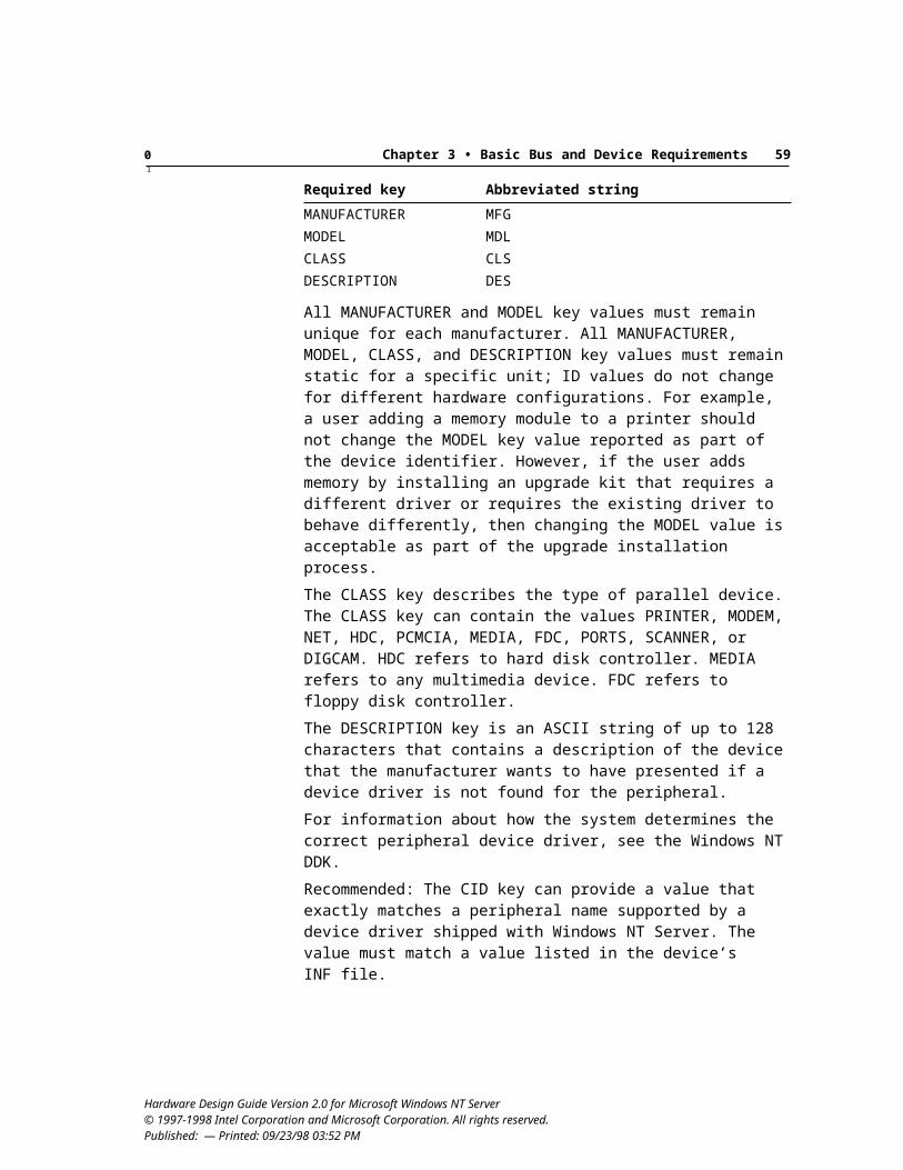
0 Chapter 4 • Basic Networking and Communications Requirements 641
In contrast to DOCSIS, both the 802.14 and the DVB/DAVIC efforts are focused on using ATM, typically implementing an ATM adapter interface and using an NDIS 5.0 ATM miniport driver.
110 Device is implemented as an integrated cable modemRecommended
An integrated cable modem should be used for servers. This recommendation means integrating everything from the cable modem’s physical interface layer, such as an RF coax connector, up through a standard PC 802.3/DIX Ethernet or ATM adapter MAC interface onto a single device. In other words, the software perceives the integrated cable modem as a standard Ethernet or ATM network adapter.
An example of this is a USB-attached DOCSIS implementation that integrates cable modem Physical Media Dependent (PMD), downstream convergence, cable MAC, link security, 802.3/DIX MAC “adapter” filtering, and USB device interface functions in the same box. Similar devices can be implemented that are attached using PCI or IEEE 1394 buses.
111 Integrated cable modem meets network adapter requirementsRequired
For the integrated cable modem, the following network adapter requirements must be met:
#65, Adapter automatically senses presence of functional network connection #67, Adapter can transmit packets from buffers aligned on any boundary #68, Adapter communicates with driver across any bridge #69, Adapter supports filtering for at least 32 multicast addresses #77, Device Bay network adapter meets requirements #78, PCI network adapters are bus masters #79, USB or IEEE 1394 network device complies with related device class
specifications
For the integrated cable modem exposing an ATM interface, the following requirements must be met as defined in “Network Adapter Requirements” earlier in this chapter:
#61, Adapter uses NDIS 5.0 [connection-oriented] miniport driver
For the integrated cable modem exposing an Ethernet interface, the following requirements must be met as defined in “Network Adapter Requirements” earlier in this chapter:
Hardware Design Guide Version 2.0 for Microsoft Windows NT Server© 1997-1998 Intel Corporation and Microsoft Corporation. All rights reserved. Published: — Printed: 09/23/98 03:52 PM
0 Chapter 4 • Basic Networking and Communications Requirements 651
#61, Adapter uses NDIS 5.0 miniport driver #69, Adapter supports filtering for at least 32 multicast addresses #74, Adapter and driver support promiscuous mode
112 Integrated cable modem exposes an ATM or Ethernet interfaceRequired
Refer to ATM Adapter requirements for ATM-specific requirements if an ATM/cable modem solution is implemented.
ISDN RequirementsThis section summarizes requirements for Integrated Service Digital Network (ISDN) hardware.
Under these guidelines, ISDN is recommended, but not required, for high-speed connections. If implemented in a server system, ISDN must meet the requirements defined in this section.
There are two classes of ISDN adapters:
Serial port devices, supported by Unimodem with INFs Parallel bus devices, supported by NDIS WAN drivers
In this section, “internal ISDN device” refers to the ISDN terminal adapter, which exposes raw access to its B channels using NDIS miniports. WDM supported bus classes, such as USB or IEEE 1394, also can be used to attach external devices using NDIS miniports.
“ISDN modem” refers to an internal or external ISDN device that exposes itself as a modem controlled by the AT command set. To the operating system, these devices look like and can be used as modems, provided that the hardware manufacturer has done work to ensure these devices have the following capabilities:
Interpretation of the standard modem AT command set, either in the ISDN device itself or in a serial port driver. For more information, see the TIA-602 specification, which is a subset of ITU V.250.
A modem INF file for installing the device and for telling Unimodem which commands to use to control the ISDN device.
Hardware Design Guide Version 2.0 for Microsoft Windows NT Server© 1997-1998 Intel Corporation and Microsoft Corporation. All rights reserved. Published: — Printed: 09/23/98 03:52 PM
0 Chapter 4 • Basic Networking and Communications Requirements 661
Serial ISDN ModemsThe requirements in this section apply for a serial ISDN modem designed for or included with a server system that complies with Hardware Design Guide Version 2.0 for Windows NT Server.
ISDN modems share the following features:
ISDN Basic Rate interface (2B+D) Serial AT command language, with proprietary ISDN extensions
ISDN modems also share the following differences from wireline PSTN modems:
User (or device) must configure for switch type and service profile ID (SPID)
Data only, in increments of one or two 64,000 bps B channels Fax not available V.42 and V.42bis usually not available
113 ISDN modem supports required command setRequired
An ISDN modem must support basic AT commands: TIA-602, which is a subset of ITU V.250. The ISDN modem shall support commands to select the end-to-end protocol used over the ISDN; synchronous PPP, V.110, V.120, and so on. Also, commands must be included to set the switch type, subscriber numbers or directory numbers (where applicable), and SPID or EAZ (where applicable), to allow user selection if auto-detection fails. These can be implemented in the device or in the communications driver.
114 ISDN modem exposes both B channelsRecommended
ISDN modems should expose both B channels so that they can leverage the multilink PPP support included in the operating system.
Multilink PPP, as defined in RFC 1717, combines several ISDN B channels to increase the bandwidth of PPP links.
When using ISDN modems connected to the server using a single serial port, the capabilities included in the operating system cannot be leveraged and the users may not be able to fully benefit from the features in the ISDN device, such as supporting two B-channels and combining them into one fast link.
This is because Windows NT cannot see both B channels of the ISDN connection unless each B channel is exposed to the operating system, either as a COM port, or by way of NDIS.
Hardware Design Guide Version 2.0 for Microsoft Windows NT Server© 1997-1998 Intel Corporation and Microsoft Corporation. All rights reserved. Published: — Printed: 09/23/98 03:52 PM
0 Chapter 4 • Basic Networking and Communications Requirements 671
External ISDN modems should be on a port fast enough to expose the full bandwidth of both B channels, such as USB. Providing two separate COM-port cables is not an acceptable solution.
115 ISDN modem supports asynchronous-to-synchronous conversionRequired
These types of ISDN devices are treated as modems, not as internal ISDN devices supported using NDIS WAN miniports. In the external case, the primary implication is that the operating system will send byte-level PPP, also known as asynchronous PPP. In the NDIS WAN case, the implication is that the operating system will send bit-level PPP, also known as synchronous PPP.
Because ISDN is a synchronous service and an ISDN modem connects to an asynchronous port on the system, the device must provide some means of converting asynchronous data to synchronous data.
116 ISDN modem uses high-speed portRecommended
Because of speed limitations inherent in a server’s COM ports, the connection for ISDN modems should be high speed, such as USB or IEEE 1394. A specification for controlling an ISDN TA over USB is in development by the USB Communications Device Class working group.
117 ISDN modem driver supports unattended installation, with limitationsRequired
Configuration of the dependent parameters, such as SPIDs and switch-type IDs, must be done using the ISDN Configuration Wizard included in the operating system.
Parallel ISDN DevicesThis section defines general requirements for ISDN and specific requirements for ISDN terminal adapters.
118 Internal ISDN device meets network adapter requirementsRequired
The driver must support NDIS 5.0. Only NDIS 5.0 miniport drivers and INF files are allowed for complete user-friendly installation and operation of the ISDN adapter. The following network adapter requirements must be met:
#61, Adapter uses NDIS 5.0 [connection-oriented] miniport driver, with call manager support
#65, Adapter automatically senses presence of functional network connection #67, Adapter can transmit packets from buffers aligned on any boundary #68, Adapter communicates with driver across any bridge #77, Device Bay network adapter meets requirements #78, PCI network adapters are bus masters
Hardware Design Guide Version 2.0 for Microsoft Windows NT Server© 1997-1998 Intel Corporation and Microsoft Corporation. All rights reserved. Published: — Printed: 09/23/98 03:52 PM
0 Chapter 4 • Basic Networking and Communications Requirements 681
#79, USB or IEEE 1394 network device complies with related device class specifications
119 Internal ISDN device supports synchronous HDLC framingRequired
High-level data link control (HDLC) framing is a standard for sending synchronous data. Other framing methods are allowed if the miniport driver provides simple HDLC framed synchronous PPP packets to NDIS.
120 Internal ISDN device and driver support raw unframed synchronous B channel I/ORequired
The internal ISDN device and the driver must support raw unframed (non-HDLC) synchronous B channel I/O at 64 Kbps for each B channel, with each B channel individually accessible. This will enable H.320 and voice calls over ISDN without audio breakup.
For these raw interfaces, the direct path to each B channel must support synchronous transmission and reception of H.221 frames, which are of 20 ms duration. To achieve this without additional latency to H.221, there must be support for overlapped I/O buffers at intervals of less than or equal to 20 ms in each direction. As underruns or overruns cause degraded audio, hardware buffering must be adequate to prevent B channel underruns and overruns. For Windows NT 5.0, 20 ms is adequate.
This can be achieved by making buffering software configurable with adequate range to handle foreseeable real-world conditions. The miniport driver should make I/O completion callbacks to NDIS for each I/O buffer as soon as the I/O for that buffer is complete and should not coalesce or delay callbacks.
121 Driver for ISDN internal device supports unattended installation, with limitationsRequired
Configuration of the dependent parameters, such as SPIDs and switch-type IDs, must be done using the ISDN Configuration Wizard included in the operating system.
122 ISDN device with U-interface includes built-in NT-1 capabilityRecommended
Note: This recommendation applies only in the United States.
A network terminator (NT-1) splits the duplexed transmit and receive signals from the ISDN line into separate transmit and receive components. An ISDN device with a built-in NT-1 can connect directly to the ISDN line. However, doing so prevents other devices from being attached to the ISDN line because only one NT-1 can be connected to an ISDN line. If the ISDN device has a built-in NT-1, it also should have a connector for either analog phone or another ISDN device (S/T-interface), such as an ISDN phone.
Hardware Design Guide Version 2.0 for Microsoft Windows NT Server© 1997-1998 Intel Corporation and Microsoft Corporation. All rights reserved. Published: — Printed: 09/23/98 03:52 PM
0 Chapter 4 • Basic Networking and Communications Requirements 691
Adding an analog (POTS) port or S/T-interface to the ISDN device delivers convenience to the SOHO market, allowing customers to use one ISDN line to meet all their telecommuting needs at minimal cost. Many customers do not want a separate analog or digital phone line for their fax machines, modems, or phone when ISDN can do this with a device that has a POTS port or S/T-interface.
123 Internal ISDN device has software-selectable terminating resistorsRequired
If the ISDN device has an S/T-interface for connecting additional ISDN devices and has configurable terminating resistors, they must be software configurable. The software selectable resistors can be selected on or off. The default value of termination is on in North America, but off in all countries where phone companies unconditionally provide the termination.
IrDA Requirements for CommunicationsInfrared capabilities are neither required nor recommended on servers. If they are implemented, they must meet the requirements in this section.
The interface between Infrared Data Association (IrDA) hardware (framers) and the Windows IrDA stack is through NDIS 5.0 miniport drivers that adhere to the conventions described in Infrared Extensions to the NDIS Version 4.0 Functional Specification. The Windows NT IrDA stack expects that the hardware and NDIS drivers deal with framing, transparency, and error detection, and also support media sense and speed change commands. Miniport drivers are responsible for discarding incoming frames with bad cyclic redundancy checks. These frames must never be forwarded to the protocol.
124 Infrared device meets network adapter requirementsRequired
The following network adapter requirements must be met:
#61, Adapter uses NDIS 5.0 miniport driver #67, Adapter can transmit packets from buffers aligned on any boundary #77, Device Bay network adapter meets requirements #78, PCI network adapters are bus masters #79, USB or IEEE 1394 network device complies with related device class
specifications
125 Infrared device supports both FIR and SIRRequired
All infrared devices must comply with approved IrDA specifications, including support for SIR and FIR data devices.
Hardware Design Guide Version 2.0 for Microsoft Windows NT Server© 1997-1998 Intel Corporation and Microsoft Corporation. All rights reserved. Published: — Printed: 09/23/98 03:52 PM
0 Chapter 4 • Basic Networking and Communications Requirements 701
126 IrDA hardware reports a unique Plug and Play ID sufficient to support unattended driver installationRequired
FIR Plug and Play hardware must report a unique Plug and Play ID that matches the combination of the chip set, transceiver, and any other system specific parameters, in order for the operating system to find and install the correct INF, and the associated driver for the IrDA hardware.
In the best case, the IrDA hardware has only one Plug and Play ID, associated INF file, and a miniport driver that can auto detect the transceiver type and other system specific parameters. This enables the installation and configuration of the hardware and the driver without any user intervention.
In other cases, for example, where the driver can not autodetect the transceiver type, or any other system specific parameters, a unique Plug and Play ID for each combination of the chip set and the transceiver type must be reported, and an associated driver and INF file describing the configuration parameters must be provided by the vendor for each combination.
Hardware Design Guide Version 2.0 for Microsoft Windows NT Server© 1997-1998 Intel Corporation and Microsoft Corporation. All rights reserved. Published: — Printed: 09/23/98 03:52 PM
0 Chapter 4 • Basic Networking and Communications Requirements 711
Hardware Design Guide Version 2.0 for Microsoft Windows NT Server© 1997-1998 Intel Corporation and Microsoft Corporation. All rights reserved. Published: — Printed: 09/23/98 03:52 PM
72
C H A P T E R 5
This section summarizes the requirements for storage devices used with servers.
Tips for selecting high-performance storage components. For manufacturers who want to select high-performance components for server systems, the following are the design features to look for in storage components:
System relies on the SCSI or Fibre Channel controller for primary storage. Controller supports bus mastering, which is a requirement in these guidelines. Disks support reduced latency and fast rotational speeds. Drivers are tuned for 32-bit performance; 32-bit alignments on the adapter
interface have no 16-bit alignments on odd addresses. Components do not use ISA. SCSI differential devices must support DIFFSENS as described in SCSI-3. PCI burst mode reduces disk controller time spent on the PCI bus.
Storage Device General RequirementsThis section presents general requirements for controllers and peripherals.
Note: It is recognized that OEMs supply systems with specific feature requirements to corporations, which can include providing servers that do not include any disks installed before shipping to a particular corporate client. However, the system must include at least the minimum required configuration for testing.
127 Non-ISA host controllers and devices support bus masteringRequired
Bus master capabilities must meet the related specification for the particular controller.
Hardware Design Guide Version 2.0 for Microsoft Windows NT Server © 1997-1998 Intel Corporation and Microsoft Corporation. All rights reserved. Published: — Printed: 09/23/98 03:52 PM
Storage Device Requirements
0 Chapter 5 • Basic Storage Device Requirements 731
The host controller must not use the ISA bus. An exemption exists for ISA-based, ATA-connected CD drives used solely for the purpose of installing software on a server system. Such devices cannot be used for any other purpose, including access to data by client systems.
Note: This requirement does not apply to legacy FDCs and will not become a requirement for the FDC in the future.
128 System and Option ROMs support Int 13h ExtensionsRequired
The Int 13h Extensions ensure correct support for high-capacity drives. Support for the fixed-disk access subset of Int 13h Extensions must be provided in the system BIOS and in any option ROMs for storage devices that include BIOS support. For information about the Int 13h Extension APIs, see the Windows NT 5.0 DDK.
Support for drives with capacities greater than 8.4 GB must be provided through the extended services—functions 4xh and greater—of the Int 13h Extensions as defined in Information Technology Enhanced BIOS Services for Disk Drives [T13-1226DT], Revision 7 or later, (available at ftp://fission.dt.wdc.com/pub/standards/x3t13/project/). The system BIOS should support the use of logical block addressing (LBA) from drives with LBA addressable area greater than 16,515,072 sectors.
Recommended: BIOS interrupt services should provide a protocol-independent method using the Int 40h extension to support ATAPI floppy drives as specified in the ARMD Specification, Version 1.0.
129 Block rewritable optical ATAPI device complies with SFF 8070iRequired
The SFF 8070i standard defines the requirements for block rewritable ATAPI devices (optical storage devices), including specifications for logical unit number (LUN) implementation, media status notification, and device write protection. This definition includes required support for the Read Format Capacities command.
Hardware Design Guide Version 2.0 for Microsoft Windows NT Server© 1997-1998 Intel Corporation and Microsoft Corporation. All rights reserved. Published: — Printed: 09/23/98 03:52 PM
0 Chapter 5 • Basic Storage Device Requirements 741
130 Controller and peripherals support media status notificationRequired
The following list shows the required specifications for implementing media status notification, depending on device type.
Device type Media status notification implementation
CD and DVD devices
Required. Comply with ANSI NCITS T10 Multi-Media Command Set-2 (MMC-2) standard for Media Status Event Notification.
ATA non-ATAPI removable storage devices
Required. Comply with Media Status Notification, Version 1.03.
ATAPI floppy/optical direct access drives
Required. Comply with either ANSI NCITS T10 Multi-Media Command Set-2 (MMC-2) standard for Media Status Event Notification or SFF 8070i Version 1.1.
Other ATA/ATAPI devices, including tape drives
Recommended. If implemented, comply with Media Status Notification, Version 1.03 or SFF 8070i.
Other types of SCSI removable devices
Recommended. If implemented, support based on NCITS Reduced Block Commands (RBC; T10/97-260r0) standard is recommended.
IEEE 1394 storage devices
Required. Comply with NCITS Reduced Block Commands (RBC; T10/97-260r0) standard.
131 Operating system recognizes the boot drive in a multiple-drive systemRequired
The implementation of boot-drive determination in multiple-drive systems is defined in Section 5.0 of the Compaq, Intel, Phoenix BIOS Boot Specification, Version 1.01. This is the format that Windows NT uses for determining the boot drive when new bootable devices are introduced for servers. The system designer can use an equivalent method for boot-drive determination, but the method must ensure that the boot drive is recognized by the Windows NT operating system.
132 USB-based mass storage device meets design guide requirements for USBRequired
If a USB-based mass-storage device (including tape, UHD floppy drive, and CD drive) is implemented in a server system, it must meet the requirements in this design guide and the requirements defined in Universal Serial Buss Device Class Definition for Mass Storage Devices, Version 1.0 or later.
Hardware Design Guide Version 2.0 for Microsoft Windows NT Server© 1997-1998 Intel Corporation and Microsoft Corporation. All rights reserved. Published: — Printed: 09/23/98 03:52 PM
0 Chapter 5 • Basic Storage Device Requirements 751
133 IEEE 1394-based mass storage meets requirementsRequired
If an IEEE 1394 storage device is implemented in a server system, it must meet any 1394 requirements in this design guide and must comply with 1394 Open Host Controller Interface Specification, Revision 1.0 (OpenHCI).
A removable IEEE 1394 mass storage device must not be the primary boot device.
SCSI Controllers and PeripheralsSCSI is a flexible I/O bus that is used in the design of a variety of peripherals, including disk drives, CD drives, tape drives, magneto-optical drives, and scanners. This section presents the requirements for SCSI hardware that is compatible with Windows NT, including adapters, peripherals, and any device that uses a SCSI controller.
134 System includes SCSI host controller and SCSI peripheralsWindows NT Server Enterprise Edition Small Business Server
Basic Server: Recommended Required RecommendedEnterprise: Recommended Required RecommendedSOHO: Recommended Required Recommended
Recommended: Fibre Channel, especially for servers running Windows NT Server/Enterprise Edition.
Note: Servers that implement Fibre Channel as the storage connection are not required to also provide SCSI capabilities.
The SCSI host adapter is the circuitry that serves as an interface between the system and one or more SCSI peripherals. A host adapter can be a card that plugs into the system’s expansion bus, such as a PCI card, or it can be designed directly into the system board set.
The host controller must support PCI bus mastering, with bus mastering enabled by default.
135 SCSI controllers provide multi-initiator support if the controller provides external device connection capability for use as a cluster nodeRequired
Multi-initiator support allows two SCSI controllers—each installed in a separate computer system—to coexist on a shared SCSI bus with a set of shared devices.
For use in a system intended as a node in a cluster using shared SCSI, the SCSI IDs must be changeable from the default SCSI controller ID of 7, and the boot time SCSI bus reset operation must be able to be disabled on each controller attached to a shared bus.
Hardware Design Guide Version 2.0 for Microsoft Windows NT Server© 1997-1998 Intel Corporation and Microsoft Corporation. All rights reserved. Published: — Printed: 09/23/98 03:52 PM
0 Chapter 5 • Basic Storage Device Requirements 761
For any SCSI controller with external connectors that is capable of being used as a node in a cluster, as described previously, the connector must be clearly labeled as available for cluster connections. This labeling must be positioned so that it is clearly visible to a user when attaching external devices to the affected external connector.
136 SCSI option ROMs support virtual DMA servicesRequired
Plug and Play SCSI host adapters must support virtual DMA services in the host-adapter option ROM, together with the required bus-mastering support. Virtual DMA supports scatter/gather capabilities, solving the problem of mapping linear addresses (segment:offset) into physical addresses.
137 Bus type is clearly indicated on connectors for all adapters, peripherals, cables, and terminatorsRequired
Connectors for each Fibre Channel or SCSI adapter, peripheral, cable, and terminator must be clearly labeled to show the bus type. All external SCSI connectors must display the appropriate SCSI icon defined in Small Computer Interface (SCSI-3) Parallel Interface (SPI) specification, Annex F, plus any clarifying abbreviations or acronyms. The following shows the related acronyms and their definitions:
DIFF — Differential. A signal type used in external large storage cabinets. SGL — Single-ended. The most commonly used signal type, such as found in
home PCs and high-end workstations. LVD — Low voltage differential. A signaling method similar to DIFF but
with lower signaling voltages supporting higher transfer rates.
138 Differential devices support DIFFSENS as defined in SPI standardRequired
Without DIFFSENS, the differential bus drivers or a single-ended device will suffer fatal thermal damage if a single-ended device is put on a differential bus.
The specification for DIFFSENS is defined in Section 5.4.2 of the SPI standard.
139 Automatic termination circuit and SCSI terminators meet SCSI-3 specificationRequired
Parallel SCSI add-on adapters and on-board controllers must use automatic termination that allows a user to add external devices without removing the server case. Terminators used in the SCSI host adapter must be regulated terminators, which are also known as active, SCSI-3 SPI, SCSI-2 alternative-2, or Boulay terminators. SCSI termination built onto internal cables must meet the SCSI-3 specification.
Hardware Design Guide Version 2.0 for Microsoft Windows NT Server© 1997-1998 Intel Corporation and Microsoft Corporation. All rights reserved. Published: — Printed: 09/23/98 03:52 PM
0 Chapter 5 • Basic Storage Device Requirements 771
140 Terminator power is supplied to the SCSI bus, with over-current protectionRequired
The host adapter must supply terminator power (TERMPWR) to the SCSI bus for system-board implementations using PCI or another expansion bus. All terminators on the external SCSI bus must be powered from the TERMPWR lines in the SCSI bus.
In addition, the circuit that supplies TERMPWR must have overcurrent protection built into it. Devices that provide TERMPWR must also provide some means of limiting the current through use of a self-resetting device. For example, a positive-temperature coefficient device or circuit breaker can be designed into the circuit. These devices open during an over-current condition and close after the condition ends.
141 External connector meets SCSI-2 or later specificationRequired
If an external connector is implemented, it must meet the requirements defined in SCSI-2 or a later specification.
142 Controller and peripherals implement SCSI data protection signalRequired
All SCSI peripherals and the SCSI host adapter must implement the SCSI bus data protection signal defined in the SPI standard, and data protection must be enabled by default.
143 SCSI connections use keyed and shrouded connectorsRequired
For internal and external configurations, the SCSI bus cable must be plugged into shrouded and keyed connectors on the host adapter and devices. This ensures that the cable is properly positioned so the user cannot plug in cables incorrectly. For internal configurations, pin 1 orientation must be designated on one edge of the ribbon cable and also on the keyed connector for the SCSI peripheral device.
For an external configuration, the SCSI connector must not use the same connector type as any other non-SCSI connector on the system.
144 External devices use automatic termination, an external pluggable terminator, or an accessible on-board termination switchRequired
The recommended implementation for an external SCSI peripheral device is to provide automatic termination. In the absence of automatic termination, a mechanical means must be provided for setting termination and the switch must be accessible to the user without opening the server case or device chassis.
145 Shielded device connector meets SCSI-2 or later specificationRequired
Device connectors must meet the specifications defined in SCSI-2 or later.
Hardware Design Guide Version 2.0 for Microsoft Windows NT Server© 1997-1998 Intel Corporation and Microsoft Corporation. All rights reserved. Published: — Printed: 09/23/98 03:52 PM
0 Chapter 5 • Basic Storage Device Requirements 781
146 SCAM support is disabled by defaultRequired
If SCAM support is present, it must be disabled by default. SCAM is not supported by the Windows NT operating system; enabling SCAM can cause the system to become unstable or inoperable.
147 Hardware supports the STOP/START UNIT command as defined in the SPI specificationRequired
The hardware in SCSI peripherals must be able to fully recover from a software-initiated spin down without rebooting the system or cycling power. To properly support power management on SCSI drives and to ensure that the operating system responds to appropriate driver calls, be sure to correctly implement the STOP/START UNIT command as defined in the SPI (SCSI-3) standard.
148 STOP/START UNIT command can be used to decrease power consumptionRecommended
Wherever appropriate, for example, for storage disks, the STOP UNIT command can be used to decrease power consumption of the base platform.
149 SCSI devices that support hot-plugging meet design guide requirementsRequired
To ensure reliable support for hot-plugging capabilities, the following requirements must be met by any SCSI devices that allow hot-plugging:
Hot-plugging for PCI devices uses ACPI-based methods. Windows NT 5.0 supports dynamic enumeration, installation, and removal of devices connected by way of the PCI bus only if there is a supported hardware insert/remove notification mechanism as defined in Section 5.6.3 of the ACPI 1.0 specification.In order to properly function with the native support in the operating system, developing industry standards such as those referred to as PCI Hot Plug and Compact PCI must use ACPI-based methods for supporting hardware insertion and removal as defined in the ACPI 1.0 specification.
All removable media support media status notification. Removable media must support the appropriate media status notification method to ensure that no loss of data or system failure results when such media is removed from the system. See requirement #130, “Controller and peripherals support media status notification.”
Recommended: A locking mechanism to ensure that devices are removed only under operating system control or during sleep or off states. For implementation details and additional design guidelines, see the article about hot-plugging support at http://www.microsoft.com/hwdev/busbios/rem_devs.htm.
Hardware Design Guide Version 2.0 for Microsoft Windows NT Server© 1997-1998 Intel Corporation and Microsoft Corporation. All rights reserved. Published: — Printed: 09/23/98 03:52 PM
0 Chapter 5 • Basic Storage Device Requirements 791
ATA Controllers and PeripheralsThis section presents requirements for ATA hardware that is compatible with Windows NT, including adapters, peripherals, and any device that uses an ATA controller.
150 System does not include ATA host controller and peripheralsWindows NT Server Enterprise Edition Small Business Server
Basic Server: Recommended Required RecommendedEnterprise: Recommended Required RecommendedSOHO: Recommended Required Recommended
ATA disks should not be present in a server, and ISA-based ATA is not allowed for servers. If ATA is implemented in a system, the ATA host controller and peripheral must meet all related requirements for devices and drivers, and they must meet the requirements defined in this section.
A server running Windows NT Server/Enterprise Edition can use an ATA device only as a boot or installation device.
151 ATA controller and peripherals comply ATA/ATAPI-4 standardsRequired
All ATA controllers and peripherals must meet the hardware and software design requirements listed in the current version of the ATA/ATAPI-4 Revision 17 standard or later.
152 Dual ATA adapters use single FIFO with asynchronous access or dual FIFOs and channelsRequired
PCI dual ATA adapters must be designed so that either channel can be used at any time; the operating system must not have to serialize access between the primary and secondary channel. Therefore, either the two channels are totally independent or a hardware arbitrator protects anything shared, such as a PIO read pre-fetch buffer.
A design implementing a single FIFO with a hardware solution to synchronize access to both channels meets this requirement if the design does not require that a request on one channel be completed before another can be started. A software-based solution is not acceptable.
ATA-based systems must be tested with ATA DMA enabled; the system must not have an embedded single-FIFO dual-channel ATA controller.
Section 5.0 of the Compaq, Intel, Phoenix BIOS Boot Specification defines the implementation for dual asynchronous channels.
Dual-channel controllers that require special software to serialize channel I/O for a single prefetch FIFO do not meet these requirements. Such designs require serial access to one of four devices, defeating the primary advantage of
Hardware Design Guide Version 2.0 for Microsoft Windows NT Server© 1997-1998 Intel Corporation and Microsoft Corporation. All rights reserved. Published: — Printed: 09/23/98 03:52 PM
0 Chapter 5 • Basic Storage Device Requirements 801
asynchronous dual-channel controllers. Furthermore, such devices are non-standard and require custom driver support.
153 System BIOS and devices support LBA if system uses ATARequired
To enable support for ATA disk drives have capacities greater than 528 MB, the system BIOS must use LBA— the LBA bit in the Device/Head register must be set to one— for all read and write operations to the device. The ATA 1226 technical report defines the proper implementation of LBA.
Although ATAPI was defined to be transparent to the BIOS, the BIOS must recognize the presence of ATAPI devices using the signature defined in SFF 8020i.
154 System BIOS supports ARMDRecommended
The system BIOS or option ROM should provide boot support for ATAPI bootable floppy disk drive in compliance with ATAPI Removable Media BIOS Specification (ARMD), Version 1.0 or later. Complying with this specification provides Int13h and Int40h support for bootable floppy drives as the primary or secondary floppy device.
155 ATA controller and peripherals support Ultra-DMARequired
All controllers and ATA peripherals must support Ultra DMA (also known as Ultra-ATA) at transfer rates up to 33 MB per second as defined in ATA/ATAPI-4 Revision 17. In addition to improved transfer rates, Ultra DMA also provides error checking for improved robustness over previous ATA implementations. PCI chip sets must implement DMA as defined in SFF 8038i.
ATA drives must comply with ATA-4, which defines the programming register set for PCI ATA bus master DMA, to ensure fully featured hardware and Windows-compatible device driver support.
Recommended support includes:
Controller and peripherals support Ultra-DMA/66. Ultra DMA for ATAPI devices. If a device does not support the Ultra DMA
transfer protocol, it must, at least, implement the termination scheme required by this protocol to ensure that all devices coexist with UDMA-33 devices.
The system BIOS should configure the drive and host controller, optimized for Ultra DMA operation if possible, though the PIO mode must continue to work. The ACPI software should also support the restoration of these settings in ACPI control methods _GTM, _STM, and _GTF, for which there are no standard registers, if the controller loses timing context across a suspend and resume cycle. The BIOS pre-operating system boot disk services, INT13h read and write, need not actually use Ultra DMA for access to the drive prior
Hardware Design Guide Version 2.0 for Microsoft Windows NT Server© 1997-1998 Intel Corporation and Microsoft Corporation. All rights reserved. Published: — Printed: 09/23/98 03:52 PM
0 Chapter 5 • Basic Storage Device Requirements 811
to operating system boot. Definitions for the above ACPI control methods can be found in Section 5 of the ACPI 1.0 specification.
An exemption exists for ISA-based, ATA-connected CD drives used solely for the purpose of software installation on a server system. Such devices cannot be used for any other purpose, including access to data by client systems.
156 ATA controller and peripheral connections include Pin 1 cable designation with keyed and shrouded connectorsRequired
Pin 1 orientation must be designated by one edge of the ribbon cable and also on the keyed connector of the ATA or ATAPI controller and peripheral device. Designation of the keyed connector must be clearly indicated on or near the connector.
157 ATAPI peripherals comply with ATA/ATAPI-4Required
This standard defines standard hardware and software design guidelines for ATAPI devices. See also requirement #126, “System and Option ROMs support Int 13h Extensions.”
158 BIOS enumeration of all ATAPI devices complies with ATA/ATAPI-4Required
This standard defines the enumeration process for all ATAPI devices.
159 ATAPI devices support DEVICE RESET commandRequired
ATAPI devices must respond to the DEVICE RESET command regardless of their internal state, as defined in the ATA/ATAPI-4 standard. The controller can be reset by going into a power-on state (requests cleared, signature present), but any non-default mode values must be left in their current state with the DRV bit unchanged.
Devices that do not implement the PACKET command feature set, such as hard disk drives, must not implement the DEVICE RESET command.
160 ISA address ranges 3F7h and 377h are not claimed by ATA controllersRequired
To avoid having two devices in the system claim 3F7h and 377h, these addresses must not be claimed for device registers by ATA devices.
It is recognized that some FDC devices claim this range. Such devices can be implemented in a server system; however, the system manufacturer must ensure that only a single device in the system claims this range.
161 ATA/ATAPI device supports ATA STANDBY commandRequired
The ATA drive must implement the ATA STANDBY command according to the ATA standard. This command is defined in ATA/ATAPI-4.
Hardware Design Guide Version 2.0 for Microsoft Windows NT Server© 1997-1998 Intel Corporation and Microsoft Corporation. All rights reserved. Published: — Printed: 09/23/98 03:52 PM
0 Chapter 5 • Basic Storage Device Requirements 821
The hard disk drive should spin up and be able to complete a Read operation within 10 seconds of applying power or leaving ATA STANDBY mode and transitioning to ATA ACTIVE, as specified in the Storage Device Class Power Management Reference Specification, Version 1.0 or later.
Fibre Channel Controllers and PeripheralsThis section presents requirements for Windows NT–compatible adapters, peripherals, and any devices that use Fibre Channel technology.
162 System includes Fibre Channel controller and peripheralsWindows NT Server Enterprise Edition Small Business Server
Basic Server: Recommended Recommended RecommendedEnterprise: Recommended Recommended RecommendedSOHO: Optional Optional Optional
Fibre Channel is a technology for 1 gigabit per second data transfer that maps common transport protocols such as SCSI and IP, merging networking and high-speed I/O in a single connectivity technology. It is an open standard, defined by ANSI and OSI standards, that operates over copper and fiber-optic cabling at distances of up to 10 km.
If implemented on a server system, Fibre Channel must use the X3T11 Private Loop Direct Attach (PLDA) profile as the storage base to use the native Windows NT support. The Physical Layers implementation must comply with Fibre Channel Physical (FC-PH), Revision 4.3 or later. For more information from the Fibre Channel Association, see the web site available at http://www.fibrechannel.com.
Erasable Disk DrivesThis section presents the requirements for erasable disk drives provided with a server system or designed for use with Windows NT Server. This category in-cludes 3.5-inch, 5.25-inch, and 12-inch magneto-optical or phase-change drives and media. It does not include CD, CD-R, CD-Rewritable, and DVD drives or media.
Hardware Design Guide Version 2.0 for Microsoft Windows NT Server© 1997-1998 Intel Corporation and Microsoft Corporation. All rights reserved. Published: — Printed: 09/23/98 03:52 PM
0 Chapter 5 • Basic Storage Device Requirements 831
163 SCSI erasable drives support SCSI commandsRequired
The following commands or features must be supported by the device’s driver:
Erase (2C): full side and selected block erase Format requirements reported with Format command Mode Select: write cache disable Mode Sense: total spare blocks available, write protect status Prevent/Allow Medium Removal, Start/Stop Unit Read (28), Verify (2F) Reassign Blocks, Read Defect Data Reserve, Release Seek (SCSI CDB Opcode – 2B) Test Unit Ready, Request Sense, Read Capacity, Inquiry Write (2A), Write and Verify (2E) Write without pre-erase, for erasable optical only
Recommended: Inquiry with support for reporting serial number or other unique unit ID should be supported by the device’s driver.
CD and DVD DrivesThis section presents the requirements for CD and DVD drives.
164 System includes CD drive or other method for installing the operating systemRequired
The server system must include either CD drive support or another method to enable the installation (or reinstallation) of the operating system. In a cluster, at least one node must have a CD drive.
CD Drive RequirementsThis section summarizes requirements for CD drives. A CD drive is not required if another method is provided to support operating system installation. However, if a CD drive is present, it must comply with these requirements.
165 CD drive provides 8x or higher performanceRequired
The CD drive must support 1200 KB per second average throughput or higher performance when running in the fully on power state. For recording CD drives, a write/read speed of 2x/8x or higher performance is required.
Hardware Design Guide Version 2.0 for Microsoft Windows NT Server© 1997-1998 Intel Corporation and Microsoft Corporation. All rights reserved. Published: — Printed: 09/23/98 03:52 PM
0 Chapter 5 • Basic Storage Device Requirements 841
166 CD drive is CD-Enhanced compatibleRequired
The CD drive must be able to mount multisession CD-ROM discs, even if track 1 is Red Book audio. Microsoft recommends use of the Sony ReadTOC method for SCSI-2 multisession support, as noted in the MMC-2 standard.
CD-Enhanced support must comply with Blue Book standards, as defined in Enhanced Music CD Specification, Version 1.0.
167 CD drive supports specified logical and physical CD formatsRequired
At a minimum, the CD device must be compatible with the following formats to ensure cross-media compatibility, based on compliance with the Optical Storage Technology Association (OSTA) MultiRead Specification for CD-ROM, CD-R, CD-R/RW, and DVD-ROM Devices, Version 1.11:
Logical formats: CD Red Book (CD-Audio), Yellow Book (CD-ROM), Orange Book parts II and III (packet writing if recordable), White Book, Blue Book, and UDF version 1.5 and 2.0
Physical formats: ROM (stamped), and Orange Book part II (CD-R) and part II (CD-RW)
Note: Any ATAPI CD drive designed to play back CD-I content must return a minimum of two track entries for the READ-TOC (0x43) command. These two track entries must be a track 01 entry and a track 0xAA entry for the lead-out address. Drives that do not comply with this minimum requirement cannot play back CD-I movies.
168 ATA/ATAPI CD drive complies with SFF-8020i, v. 2.6 Required
CD drives attached to the system using the ATA interface must support the hardware and protocols documented in the ATA Packet Interface for CD-ROMs, SFF-8020i, Version 2.6 or later.
Recommended: Support for the READ CD-DA command as defined in the MMC-2 standard.
169 CD drive supports multisession and compatibility forms of the READ_TOC commandRequired
Both multisession forms (01b and 10b) as well as the compatibility form (00b) of the READ_TOC command, must be implemented. This requirement ensures complete support for CD multisession capabilities.
170 ATA/ATAPI CD changer meets MMC-2 standardRequired
If an ATAPI-compatible CD changer is present that has a capacity for seven or fewer discs, the device must comply with MMC-2 standard.
Hardware Design Guide Version 2.0 for Microsoft Windows NT Server© 1997-1998 Intel Corporation and Microsoft Corporation. All rights reserved. Published: — Printed: 09/23/98 03:52 PM
0 Chapter 5 • Basic Storage Device Requirements 851
171 System BIOS or option ROM supports El Torito No Emulation modeRequired
For server systems that include CD and DVD drives, the system BIOS or option ROM must support the No Emulation mode defined in El Torito—Bootable CD-ROM Format Specification, Version 1.0, published by IBM and Phoenix.
A removable USB mass storage device must not be the primary boot device.
172 CD drive uses push-to-close designRecommended
A motorized design is not required, but if it is implemented, the device must be designed so the user has three options to close the device when inserting a disc:
Physically push on the bay Physically push the close button on the bay housing Select a software-supported option to close the device
DVD Drive RequirementsThis section summarizes requirements for supporting DVD drives. A DVD drive is not required in a server system, but if present, it must comply with these requirements. Systems targeted for use with Windows NT Server/Enterprise Edition should provide DVD drive capabilities.
For more information about DVD support under Windows NT, see the articles at http://www.microsoft.com/hwdev/dvd/.
173 DVD device provides 2x minimum transfer rate or better performance anywhere on the diskRequired
The minimum sustained DVD device media transfer rate must be at least 2 MB per second for read operations from the DVD disk.
Recommended: A 4x DVD-ROM at 4 MB per second sustained from the DVD disk.
Hardware Design Guide Version 2.0 for Microsoft Windows NT Server© 1997-1998 Intel Corporation and Microsoft Corporation. All rights reserved. Published: — Printed: 09/23/98 03:52 PM
0 Chapter 5 • Basic Storage Device Requirements 861
174 DVD drive and controller support bus master DMA transfersRequired
If DVD capability is present in a server, the drive and controller must support byte-aligned, multisegment, bus master DMA transfers.
If attached by way of an ATA interface, ATAPI DVD drives and ATA system-board implementations must support DMA as specified in ATA/ATAPI-4.
175 DVD drive meets minimum compatibility requirementsRequired
DVD drives must support all the functionality of CD drives as outlined elsewhere in this document. Specifically, the DVD drive must be compatible with the following formats to ensure that the DVD drive can read earlier media:
Logical formats: CD Red Book (CD-Audio), Yellow Book (CD-ROM), White Book, Orange Book parts II and III (packet writing), Blue Book, UDF Version 1.5 and 2.0, and DVD video, if applicable.
Physical formats: ROM (stamped), Orange Book part II (CD-R) and part III (CD-RW), and ECMA-267 and ECMA-268 (DVD-ROM). Recommended: Support for ECMA-274 (PC+RW) and ECMA-272, 273 (DVD-RAM 1.0 and DVD-R).
Conforming to OSTA MultiRead Specification, Version 1.11 indicates compliance with all of the above CD compatibility requirements.
176 DVD drive meets MMC-2 standardRequired
The MMC-2 standard defines the implementation requirements that the Windows NT operating system supports. A DVD drive must comply with the MMC-2 standard. Additionally, the drive must support the following commands:
Beh Read CD 08h Device resetB9h Read CD MSF A0h Packet4Bh Pause/resume A1h Identify packet deviceE5h Check power mode Efh Set features90h Execute device diagnostic E6h SleepE1h Idle immediately E0h Standby immediate00h NOP
DVD drives must also support the following:
Timeout model as designed and documented in MMC-2. The Get Event Status command (Media Event Status class) and all related
commands, including Persistent Prevent/Allow, as defined in MMC-2.
Hardware Design Guide Version 2.0 for Microsoft Windows NT Server© 1997-1998 Intel Corporation and Microsoft Corporation. All rights reserved. Published: — Printed: 09/23/98 03:52 PM
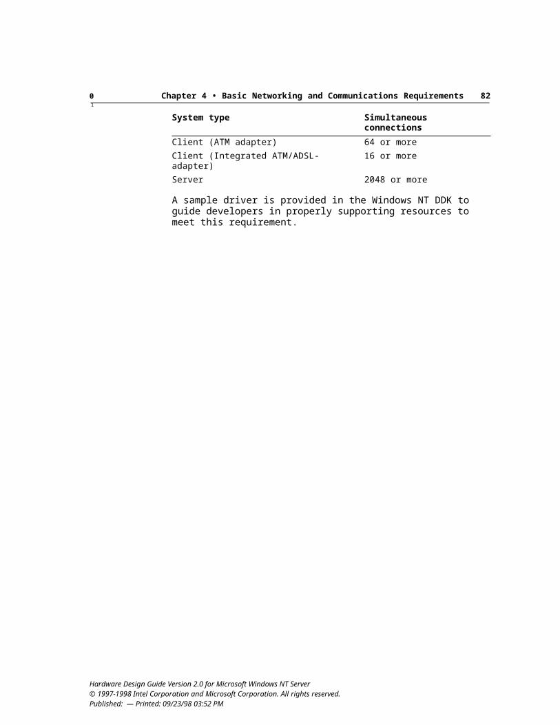
0 Chapter 5 • Basic Storage Device Requirements 871
Get Configuration command for Morphing class devices (Class 2), as defined in MMC-2. Windows uses the Get Configuration command to determine whether media event status is supported correctly.
177 DVD drive uses push-to-close designRecommended
A motorized design is not required, but if it is implemented, the device must be designed so the user has three options to close the device when inserting a disc:
Physically push on the bay Physically push the close button on the bay housing Select a software-supported option to close the device
178 DVD drive supports defect managementRequired
The drive must support the defect management that is transparent to the operating system, according to industry standards. Defect management for DVD-RAM media is defined in DVD Specifications for Rewritable Disc, Part 1: Physical Specifications, published by Toshiba Corporation. Defect management for DVD+RW is defined in ECMA-274.
179 System meets video playback requirements if DVD drive supports DVD-Video playbackRequired
The following capabilities are required for DVD drives that support DVD-Video playback:
DVD drive supports copyright protection. The drive must support a licensed content scramble system (CSS) copyright-protection scheme and provide support for CSS-protected discs to ensure proper protection for all content produced in accordance with CSS, as defined in DVD Specification, Version 1.0 or later.Software is provided as part of the Windows NT operating system support for DVD to facilitate the authentication process required by this scheme, thus allowing a DVD drive to authenticate and transfer keys with a CSS decrypter. Operating system software acts as the agent to allow either hardware or software decrypters to be authenticated.Playback of regionalized movies must be handled in accordance with the CSS requirements and the interfaces as defined in the Mt. Fuji 2.0 specification for Phase II regionalization (RPC II). Version 2.0 of the Mt. Fuji specification will be proposed to the Small Form Factor committee as SFF 8090 Version 2.0 Revision 1.0. DVD implementations should conform to this specification if it is approved before these design guide requirements take effect.
Hardware Design Guide Version 2.0 for Microsoft Windows NT Server© 1997-1998 Intel Corporation and Microsoft Corporation. All rights reserved. Published: — Printed: 09/23/98 03:52 PM
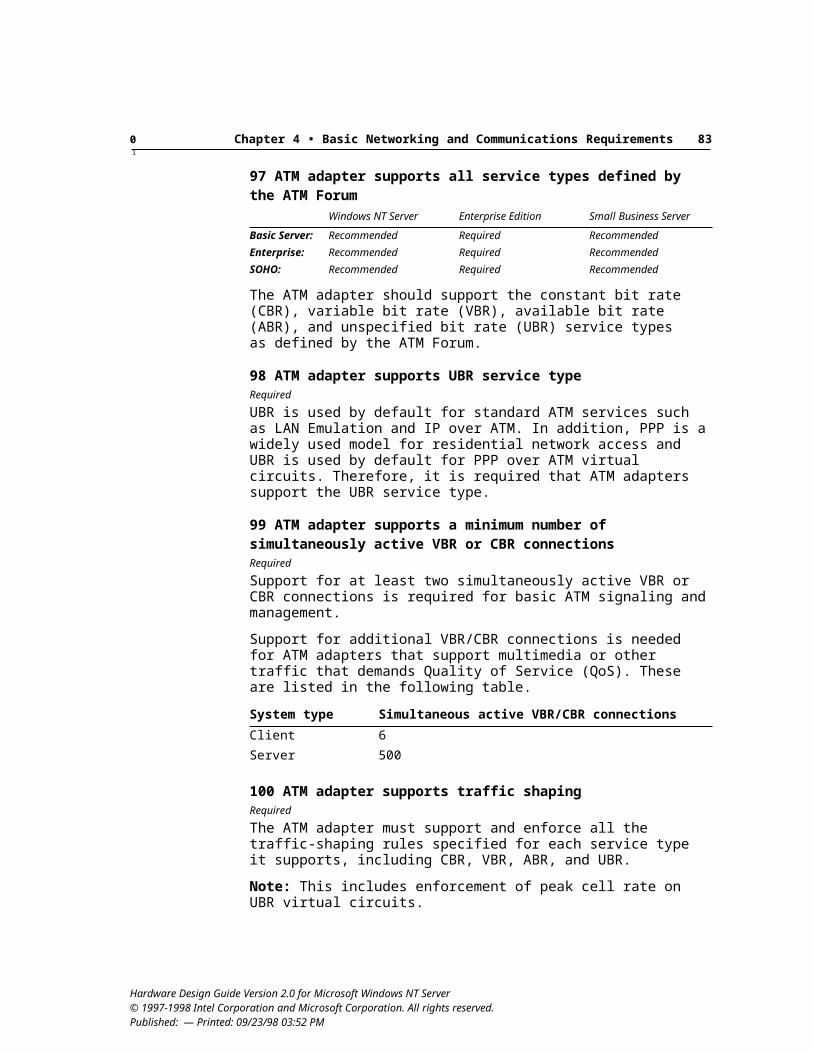
0 Chapter 5 • Basic Storage Device Requirements 881
DVD decoder driver correctly handles media types, time discontinuity, and decode-rate adjustment. This requirement specifies that the vendor-supplied minidrivers for DVD, MPEG-2, and AC-3 decoders have the following capabilities: Use correct media types. This includes validating all format block fields
on connection and on every IPin::QueryAccept message. Query for IMediaSample2 on every received media sample to test for a
time discontinuity bit. It is also acceptable to query on every video/audio frame to reduce CPU overhead.
Adjust decode rate in response to IPin::NewSegment() calls for video and subpicture.
DVD decoder supports subpicture compositing and closed captioning. The system must be capable of displaying subpicture data as well as providing closed-captioning support for all such data stored on the disc. This requires YUV offscreen surface support, as defined later in this list.Subpicture streams must be supported as defined in the DVD Specification, Version 1.0, from Toshiba Corporation. Alpha blending, or a simulation implemented in the driver, is required for static menus.
Subpicture decoder correctly handles subpicture properties and other functions. The minidriver for the subpicture decoder must be able to correctly handle the following: Set the subpicture property Turn subpicture compositing on and off Set the highlight rect parametersFor information, see the Microsoft DirectX® 5.1 SDK (provided in the Microsoft Platform SDK) and the DirectX 5.0 information in Windows NT 5.0 DDK.
System supports seamless DVD-Video 1.0 navigation. This requirement includes menu navigation and video selection, and language and subpicture track selection to support the user’s ability to navigate DVD-Video discs. Test sources include, but are not limited to, the following: Matsushita Electronics Incorporated (MEI) test disc Joe Kane Productions Video Essentials disc Microsoft test disc
Hardware Design Guide Version 2.0 for Microsoft Windows NT Server© 1997-1998 Intel Corporation and Microsoft Corporation. All rights reserved. Published: — Printed: 09/23/98 03:52 PM
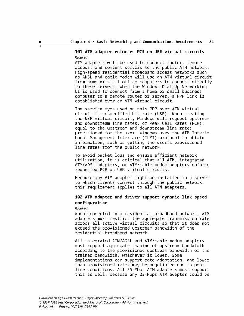
0 Chapter 5 • Basic Storage Device Requirements 891
MPEG-2 playback provides high-quality video output. MPEG-2 solutions must provide high-quality video display output, as defined by the following: Smooth frame delivery, with all video fields and frames from the MPEG
source decoded. Audio and video synchronized to within one and a half video frames,
with synchronization not allowed to drift out over time. No tearing - provide proper video buffering, such as double buffering. Correct display of multiple aspect-ratio content. The material should be
displayed according to the aspect ratio information in the MPEG header.This requires support for YUV offscreen surface and up/down interpolated scaling, as defined in the following requirement.
Graphics adapter supports DVD movie playback features. Any system with a DVD drive that includes the ability to play back MPEG-2 data streams must meet the requirements listed here. However, this requirement does not apply for systems that include DVD drive for storage purposes but do not include DVD-Video playback software. The following capabilities are required for solutions that use either hardware or software MPEG-2 decoders: Up and down scaling with bilinear interpolation. Recommended: 5 taps,
both vertically and horizontally. YUV 4:2:2 and 4:2:0 planar offscreen surface support. VGA destination color keying for video rectangle. AGP or PCI bus mastering.
Tape DrivesTape drives as backup devices can be an important part of guaranteeing data availability at a corporate site. Windows NT Server includes a graphical tool named Backup that supports tape backup of Windows NT Server-based data.
If a tape drive is provided in a server system, it must comply with the requirements and recommendations in this section.
180 System includes tape drive for local backupRecommended
System administrators will commonly want offline backup capabilities to be available. If a tape drive is provided with a server system, either as a built-in or peripheral add-on device, it must meet the minimum requirements defined in this section.
Hardware Design Guide Version 2.0 for Microsoft Windows NT Server© 1997-1998 Intel Corporation and Microsoft Corporation. All rights reserved. Published: — Printed: 09/23/98 03:52 PM
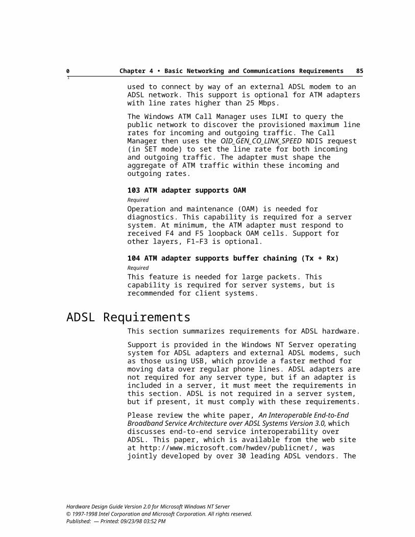
0 Chapter 5 • Basic Storage Device Requirements 901
181 Single-tape device meets minimum capacity requirementsWindows NT Server Enterprise Edition Small Business Server
Basic Server: 4 GB required 4 GB required 4 GB requiredEnterprise: 8 GB required 8 GB required 8 GB requiredSOHO: 4 GB required 4 GB required 4 GB required
Recommended: 8 GB minimum capacity for Basic and SOHO servers.
Minimum uncompressed, formatted storage capacity is required for any tape device designed to comply with these guidelines.
182 Single-tape device meets minimum speed requirements20 MB/minute required
Minimum speed capabilities are required for any tape device designed to comply with these guidelines.
183 Tape device meets industry standardsRequired
A SCSI tape peripheral must comply with the SCSI tape command set and with the requirements defined in “SCSI Controllers and Peripherals” earlier in this chapter.
ATA is not recommended for servers, but if an ATA tape peripheral is imple-mented, it must comply with the packet passing protocol defined in SFF 8020i, Version 1.2. Also, for cartridge drives, the device must comply with QIC 157, Revision D or later.
184 SCSI tape drive supports SCSI commandsRequired
The following commands or features must be supported by the device’s driver:
Erase Mode Select — compression enable/disable Mode Sense — write protect status, media type, and density code reporting Prevent/Allow Medium Removal, Load/Unload Unit Read, Verify Reserve, Release Rewind, Space, ReadPosition, Locate Test Unit Ready, Request Sense, ReadBlockLimits, Inquiry Write, Write Filemarks
Recommended: Inquiry with support for reporting serial number or other unique unit ID should be supported by the device’s driver.
Hardware Design Guide Version 2.0 for Microsoft Windows NT Server© 1997-1998 Intel Corporation and Microsoft Corporation. All rights reserved. Published: — Printed: 09/23/98 03:52 PM
0 Chapter 5 • Basic Storage Device Requirements 911
185 Win32-based backup solution provided with deviceRequired
For a tape device designed for Windows NT Server, the manufacturer must provide a Windows NT tape driver for the built-in Windows NT backup application or provide a Win32-based backup application for the device if the Windows NT Server operating system does not include built-in support for the tape drive.
A hardware vendor can also choose to include a backup application that provides additional functionality over that included in Windows NT Server, such as the ability to create and script jobs, automated scheduling of jobs, remote administration of backup, and client-server backup to remote tape devices.
Media ChangersThis section defines requirements for media changers.
CD ChangersThis section provides requirements for CD changers.
There is no requirement or recommendation for providing a CD changer with a server system, but if present or designed to be compatible with Windows NT 5.0, it must comply with these requirements.
186 CD changer for seven or fewer discs meets MMC-2 standardRecommended
If an ATAPI-compatible CD changer is present that supports seven discs or less, the device should comply with the MMC-2 standard.
Tape and Optical Disk ChangersThis section provides requirements for tape and optical disk changers. There is no requirement or recommendation for providing a tape or optical disk changer, but if a device is present or is designed to be compatible with Windows NT 5.0, it must meet the requirements defined in this section.
This includes changers that support the following drive/media types:
3.5-inch, 5.25-inch, and 12-inch magneto-optical or phase-change drives and media
All magnetic tape drives and media
It does not include changers that support CD-ROM, CD-R, CD-Rewritable, or DVD drive/media types.
Hardware Design Guide Version 2.0 for Microsoft Windows NT Server© 1997-1998 Intel Corporation and Microsoft Corporation. All rights reserved. Published: — Printed: 09/23/98 03:52 PM
0 Chapter 5 • Basic Storage Device Requirements 921
187 SCSI changer and drive support auto-configurationRequired
To meet requirements for auto-configuration of changers and their associated drives, the following changer requirements and configuration restrictions are defined:
For changers where autoconfiguration under Windows NT Media Services (NTMS) control is a targeted feature, all changer tape or optical disk drives must be connected to the same SCSI bus as the changer. Changer systems that are not configured this way will not be autoconfigurable under NTMS in Windows NT 5.0 and must provide documentation that describes the appropriate manual configuration process for use with NTMS. Examples of proper documentation are available in Appendix A of NTMS Programmers Guide, at http://www.highground.com/developer/documents/ntmsdocu.htm.
The changer’s Read Element Status–Data Transfer Element Descriptor must support the reporting of the SCSI Bus Address and LUN of each drive in the library unit.
If drive cleaning is required and can be automated, a specific slot that is accessible by way of a Move Medium command must be designated in the Operator’s Guide.
The changer must be able to report if a bar-code reader is installed in the unit.
The changer must be able to report on the current of (magazine) slots and drives by using the Read Element Status command.
188 SCSI tape and optical disk changers support SCSI commandsRequired
The following commands or features must be supported by the changer:
Initialize Element Status (with/without bar-code reading) Mode Sense—Pages 1D, 1E, 1F Move Medium Prevent/Allow Medium Removal (door access and IEPORT locking) Read Element Status Reserve, Release Send Volume Tag, Request Volume Element Address Test Unit Ready, Request Sense, Inquiry
Recommended: Inquiry with support for reporting serial number or other unique unit ID should be supported by the changer.
Hardware Design Guide Version 2.0 for Microsoft Windows NT Server© 1997-1998 Intel Corporation and Microsoft Corporation. All rights reserved. Published: — Printed: 09/23/98 03:52 PM
0 Chapter 5 • Basic Storage Device Requirements 931
Hardware Design Guide Version 2.0 for Microsoft Windows NT Server© 1997-1998 Intel Corporation and Microsoft Corporation. All rights reserved. Published: — Printed: 09/23/98 03:52 PM
94
C H A P T E R 6
This chapter summarizes physical design and hardware security requirements and recommendations.
Physical Design RequirementsThis section presents the requirements related to the physical design of servers.
189 Icons are provided for all external connectorsRequired
This requirement helps ensure that the end user can correctly make the physical connections required for adding a device to a system. This requirement includes the following:
Wherever possible, keyed or shrouded connectors or other configurations should be used to prevent misconnection. The physical design of the connector must ensure that the user cannot mistakenly insert the connector into the wrong port.
Icons are provided for all external connectors. The icons can be molded, printed, or affixed as permanent stickers, which can include text. Icons can be based on existing vendor designs or on the examples shown at http://www.microsoft.com/hwdev/desguid/icons.htm.
Systems and peripherals must use a color-coding scheme for connectors and ports. The following list displays the recommendation for standard color coding of connectors and ports. The selection of these specific colors was done using criteria established by Human Factors and Industrial Design professionals from multiple companies who are involved in the design of computer hardware.
Hardware Design Guide Version 2.0 for Microsoft Windows NT Server © 1997-1998 Intel Corporation and Microsoft Corporation. All rights reserved. Published: — Printed: 09/23/98 03:52 PM
Physical Design and Hardware Security Requirements
0 Chapter 6 • Basic Physical Design and Hardware Security Requirements 951
Connector Recommended color Pantone
Analog VGA Blue 661CAudio line in Light blue 284CAudio line out Lime 577CDigital monitor/flat panel White IEEE 1394 Grey 424CMicrophone Pink 701CMIDI/game Gold 131CParallel Burgundy 235CPS/2-compatible keyboard Purple 2715CPS/2-compatible mouse Green 3395CSerial Teal or Turquoise 322CSpeaker out/subwoofer Orange 157CRight-to-left speaker Brown 4645CUSB Black 426CVideo out Yellow 123CSCSI, network, telephone, modem, and so on
None —
It is recommended that retail peripherals also implement color coding, and those that do are required to use the colors in order to correspond with servers that adopt this scheme.
Note: It is recognized that the design for legacy ports, such as the PS/2-compatible mouse and keyboard ports, analog audio and video jacks, and the microphone and speaker jacks, will not change and therefore cannot fully meet this requirement. However, icons and labels must be provided wherever possible to help the user make the correct connections.
190 All expansion slots in the system are accessible for users to insert cardsRequired
The space for expansion cards that will reside in associated expansion slots cannot be physically blocked by components or devices provided with the system. However, this requirement does not exclude configurations that provide half-height cards for some slots, passive back planes for connectors, and so on. It is understood that in order to install expansion cards in some expansion slot implementations, users might have to temporarily move other system components to gain access to the slot. In general, designers should minimize this juggling as much as possible.
191 System and device design include protected switchesRecommended
Switches can be covered with a hood or other protection to prevent inadvertent switching. Locks can also be provided to prevent unauthorized access.
Hardware Design Guide Version 2.0 for Microsoft Windows NT Server© 1997-1998 Intel Corporation and Microsoft Corporation. All rights reserved. Published: — Printed: 09/23/98 03:52 PM
0 Chapter 6 • Basic Physical Design and Hardware Security Requirements 961
192 System design includes locking caseRecommended
The computer case can be protected with key locks to prevent unauthorized access.
Other recommended features include:
Key lock removes the computer case without additional tools—if this can be done while maintaining compliance with other safety standards.
Software management of physical components as documented in Windows Hardware Instrumentation Implementation Guidelines, Version 1.0 (WHIIG), which also defines the Windows-specific requirements of the Wired for Management Baseline Specification, Version 2.0, for hardware instrumentation.
193 System and device design include positive retention connectorsRecommended
Positive retention mechanisms should be implemented to ensure connections. The retention mechanism should be operated by hand, requiring no tools for mating and breaking the connection. It is recognized that certain legacy connector implementations, such as PS/2-compatible pointing devices and keyboards, will not generally allow this. However, locking cable connections provide a valuable feature for end users.
194 Parallel port design provides sufficient space for connector assemblyRequired
The parallel port design must provide enough space between the connectors and the surrounding enclosure to allow for a mating connector, connector shell, and latch assembly. The IEEE 1284 specification recommends an IEEE 1284-C connector for all new ports and devices.
Hardware Security RequirementsThis section summarizes the system hardware security requirements and recommendations.
A baseline measurement of a secure operating system is the U.S. National Security Agency’s criteria for a C2-level secure system. The requirements for a C2 secure system are articulated by the U.S. Department of Defense’s National Computer Security Center (NCSC) in the publication Trusted Computer System Evaluation Criteria, also known as the “Orange Book.” All systems, whether they are network operating systems or stand-alone operating systems, are evaluated under the criteria set forth in the Orange Book.
Windows NT Server was designed to comply with the NCSC’s Orange Book requirements. Every process and feature was designed with C2-level security in mind. Because the Windows NT Server C2 implementation is entirely software-
Hardware Design Guide Version 2.0 for Microsoft Windows NT Server© 1997-1998 Intel Corporation and Microsoft Corporation. All rights reserved. Published: — Printed: 09/23/98 03:52 PM
0 Chapter 6 • Basic Physical Design and Hardware Security Requirements 971
based, users will not have to install additional hardware on either their servers or clients to meet C2-level security requirements. However, the hardware must meet minimum requirements for C2 evaluation with Windows NT. The C2 evaluation report is available in the following publication:
FINAL EVALUATION REPORT Microsoft Windows NT Workstation and Server Version 3.5 with U.S. Service Pack 3. National Computer Security Center, 23 June 1995.
In addition to its C2 evaluation, both the base and the network components of Windows NT have received the F-C2, E3 ITSEC rating in the United Kingdom. This rating can be leveraged in Germany and soon in France and the Netherlands. Therefore, customers in both the U.S. and Europe can operate certifiably secure systems.
195 C2 evaluation for hardwareRecommended
C2-evaluated hardware meets requirements defined in the Orange Book.
For hardware designed for customers outside the U.S., equivalent evaluation might be defined in local standards, such as F-C2/E3 ratings in Europe.
196 Peripherals meet hardware security recommendationsRecommended
OEM-specific solutions can be implemented to meet these recommendations. The following hardware security features are recommended:
External drive devices should have locking capabilities. Each removable media device on a server system should be capable of being locked to prevent unauthorized access to data. A single locked door covering the drives is sufficient. The locking mechanism must render the device useless, whether locking is done electronically or mechanically.
Computer case and switches should have locking capabilities to prevent unauthorized internal access. An OEM-specific method can be implemented, either electronically or mechanically.
Remote software management should be supported for physical components. Controls and remote alerts should be provided for chassis-open intrusion.
For servers running either Windows NT Server or Windows NT Server/Enterprise Edition, smart card readers and cards should be provided. If provided with a server system, smart card devices must be compatible with Interoperability Specification for ICCs and Personal Computer Systems, available at http://www.smartcardsys.com/doc/content.html.
In addition, smart card readers and device drivers must be Plug and Play-compliant and must adhere to the Microsoft Smart Card DDK for the Windows and Windows NT platforms, which will be provided in the Windows NT 5.0
Hardware Design Guide Version 2.0 for Microsoft Windows NT Server© 1997-1998 Intel Corporation and Microsoft Corporation. All rights reserved. Published: — Printed: 09/23/98 03:52 PM
0 Chapter 6 • Basic Physical Design and Hardware Security Requirements 981
DDK. Smart card applications and service-provider DLLs must adhere to the Microsoft Smart Card SDK that is part of the Microsoft Platform SDK.
Hardware Design Guide Version 2.0 for Microsoft Windows NT Server© 1997-1998 Intel Corporation and Microsoft Corporation. All rights reserved. Published: — Printed: 09/23/98 03:52 PM
0 Chapter 6 • Basic Physical Design and Hardware Security Requirements 991
Hardware Design Guide Version 2.0 for Microsoft Windows NT Server© 1997-1998 Intel Corporation and Microsoft Corporation. All rights reserved. Published: — Printed: 09/23/98 03:52 PM
0 1001
C H A P T E R 7
These requirements and recommendations relate to ease of use, ease of maintenance, manageability, and failure tolerance. Design guidelines that make server configuration, management, and servicing easier for end users and administrators are defined to help reduce the total cost of ownership for servers.
Reducing the total cost of ownership is an important goal for servers; a key priority in this effort for servers is minimizing downtime. This goal is achieved through mechanisms for backup and reliability, remote management, and emergency and preboot management.
Backup and Reliability RequirementsOne of the most powerful characteristics of Windows NT Server is its reliability. Windows NT Server includes the following reliability and fault-tolerance capabilities:
Automatic restart Complete tape backup support Error handling and protected subsystems Fault tolerance using disk mirroring, disk duplexing, and disk striping with
parity (RAID 5) Recoverable file system, automatic replication of directory partitions, and
support for Backup Directory Servers Uninterruptible power supply (UPS) support
The following sections define hardware requirements and recommendations for peripheral devices that support reliability and availability under Windows NT Server.
Hardware Design Guide Version 2.0 for Microsoft Windows NT Server © 1997-1998 Intel Corporation and Microsoft Corporation. All rights reserved. Published: — Printed: 09/23/98 03:52 PM
Reliability, Availability, and Serviceability Requirements
0 Chapter 7 • Basic Reliability, Availability, and Serviceability Requirements 1011
Backup HardwareThis section defines the requirements for backup hardware for servers.
197 System includes integrated backup solutionRecommended
An integrated tape drive or other device should be included in the system. Although the recommended method to back up files on another server is to use a backup service under Windows NT Server, system administrators will commonly want offline backup capabilities to be available.
For information about hardware requirements related to backup capabilities, such as tape drives and so on, see Chapter 5, “Storage Device Requirements.”
Power SupplyThis section defines the guaranteed power requirements for servers.
198 System includes UPS provided with systemRecommended
For servers deployed in many corporate environments, the more common choice will be to provide guaranteed power for the server room.
199 System includes power supply protection using N+1 (extra unit)Windows NT Server Enterprise Edition Small Business Server
Basic Server: Recommended Recommended RecommendedEnterprise: Recommended Required RecommendedSOHO: Recommended Recommended Recommended
The system overvoltage/undervoltage protection and power supply switch-over circuitry should have the capability to regulate according to the system load. For each voltage used in the system, the output voltages of the redundant power supplies should be within the range of values that can guarantee the proper operation of the system, no matter which supply is active. Power-supply switch-over should occur swiftly enough to maintain normal server system operation.
200 System supports replacement of power suppliesWindows NT Server Enterprise Edition Small Business Server
Basic Server: Recommended Required RecommendedEnterprise: Required Required RequiredSOHO: Recommended Required Recommended
Recommended: Hot-swapping capabilities for power supply replacement and power supply redundancy.
Hardware Design Guide Version 2.0 for Microsoft Windows NT Server© 1997-1998 Intel Corporation and Microsoft Corporation. All rights reserved. Published: — Printed: 09/23/98 03:52 PM
0 Chapter 7 • Basic Reliability, Availability, and Serviceability Requirements 1021
201 System supports replacement of fansWindows NT Server Enterprise Edition Small Business Server
Basic Server: Optional Required OptionalEnterprise: Recommended Required RecommendedSOHO: Optional Required Optional
For highest reliability, hot-swap fans should be implemented to maximize server up time.
202 System includes local hot-swap power supply replacement indicatorsWindows NT Server Enterprise Edition Small Business Server
Basic Server: Recommended Required RecommendedEnterprise: Recommended Required RecommendedSOHO: Recommended Required Recommended
Any system that provides hot-swap power supply replacement and power supply redundancy should have local indicators that unambiguously indicate the supplies that must be replaced. These indicators guide service personnel to replace the correct power supply. Automatic retention mechanisms that prevent incorrect supply removal also satisfy this guideline.
Fault-Tolerant HardwareThis section provides design guidelines for fault-tolerance features and capabilities.
203 System includes multiple hard drivesWindows NT Server Enterprise Edition Small Business Server
Basic Server: Recommended Required RecommendedEnterprise: Recommended Required RecommendedSOHO: Recommended Required Recommended
Recommended: Hot-swappable drives.
Bus mastering is required for the drive controllers. Use of multiple hard drives and controllers in a server system provides both performance and reliability benefits, therefore, it is recommended for server systems.
204 System includes intelligent RAID controller with adequate storage capacity
Windows NT Server Enterprise Edition Small Business Server
Basic Server: Recommended Required RecommendedEnterprise: Required Required RequiredSOHO: Optional Required Optional
An intelligent RAID controller—where the controller itself has the capability to run the array management software locally rather than simply executing disk accesses for host-based array software—provides the benefit of reduced demands on the host processor or processors, thereby freeing those computing resources
Hardware Design Guide Version 2.0 for Microsoft Windows NT Server© 1997-1998 Intel Corporation and Microsoft Corporation. All rights reserved. Published: — Printed: 09/23/98 03:52 PM
0 Chapter 7 • Basic Reliability, Availability, and Serviceability Requirements 1031
and allowing their use by other tasks. The intelligent RAID controller may be internal to the server chassis, or within an external drive enclosure.
If an intelligent RAID controller is provided in a system, it should be capable of handling sufficient amounts of disk storage to fulfill the needs of the targeted usage model for that server. These needs will vary based on the storage-intensive nature of the server’s tasks.
205 System supports at least one of RAID 1, 5, or 1/0Windows NT Server Enterprise Edition Small Business Server
Basic Server: Recommended Required RecommendedEnterprise: Required Required RequiredSOHO: Recommended Required Recommended
RAID 1 and RAID 1/0 are recommended. RAID 5 is also acceptable. RAID 0 (for enhanced performance but no added reliability) is optional.
206 RAID support includes notification of failed driveRequired
If RAID support is implemented, notification of a failed drive must be provided by the disk subsystem, with notification sent to the system administrator.
207 RAID subsystem supports automatic replacement of failed driveWindows NT Server Enterprise Edition Small Business Server
Basic Server: Required Required RequiredEnterprise: Required Required RequiredSOHO: Recommended Required Recommended
The RAID subsystem must provide automatic replacement of a failed drive by a standby disk and must rebuild lost data without interfering with system operations.
208 RAID subsystem supports manual replacement of failed driveWindows NT Server Enterprise Edition Small Business Server
Basic Server: Recommended Required RecommendedEnterprise: Required Required RequiredSOHO: Recommended Required Recommended
The RAID subsystem should provide for manual replacement of a failed drive without shutting down or halting the system. The subsystem should also allow lost data to be rebuilt without interfering with system operations beyond some decreased performance of drive array access.
Hardware Design Guide Version 2.0 for Microsoft Windows NT Server© 1997-1998 Intel Corporation and Microsoft Corporation. All rights reserved. Published: — Printed: 09/23/98 03:52 PM
0 Chapter 7 • Basic Reliability, Availability, and Serviceability Requirements 1041
Serviceability RequirementsThis section provides design guidelines for serviceability features and capabilities.
209 System includes protected forced NMI switch for system diagnosisRecommended
The system should include a protected switch to force an NMI on a stalled system. This switch permits the system to perform a memory dump that can then be used for diagnosis of system failures. If implemented, this switch must be protected in such a way that only an authorized administrator can perform this action.
High Availability RequirementsThis section summarizes the requirements for high availability.
Through ACPI and OnNow power management capabilities, Windows NT 5.0 allows more control of dynamic configuration changes and power state changes. These features help implementers in handling event-based issues such as lights that are keyed to system failures, pending failures, or system power states.
210 System includes alert indicators for occurrence of failureWindows NT Server Enterprise Edition Small Business Server
Basic Server: Recommended Required RecommendedEnterprise: Recommended Required RecommendedSOHO: Recommended Required Recommended
Alert indicators should be provided that indicate hard failure. In addition to visual alerting mechanisms, a design can also provide software alerts such as paging, fax, or e-mail notifications.
The following are required sources of alert indicators for hard failures for systems running Windows NT Server/Enterprise Edition. These indicators are recommended for servers running other versions of Windows NT Server.
Cooling fan malfunction Disk drive error N+1 power module failure
These sources of alert indicators for hard failures are recommended for all servers:
Chassis cover open (intrusion) NMI, processor internal error, and time-out of watchdog timer
Hardware Design Guide Version 2.0 for Microsoft Windows NT Server© 1997-1998 Intel Corporation and Microsoft Corporation. All rights reserved. Published: — Printed: 09/23/98 03:52 PM
0 Chapter 7 • Basic Reliability, Availability, and Serviceability Requirements 1051
211 Hot-swappable drive includes a local disk drive replacement indicatorRequired
A hot-swappable drive must have a local indicator that shows which drive or drives are ready for replacement, facilitating the servicing process and improving reliability by reducing possible errors.
This indicator should be on the drive chassis, not on the screen. The Device Bay “eject” signal can be used to activate a replacement indicator. Designers can choose to use existing LEDs for dual purposes to fulfill this requirement, but the LED display should clearly show when a drive is ready for removal, as opposed to other information the display would normally provide.
For systems with multiple drives, an individual replacement indicator should be physically associated with each hot-swappable drive slot.
212 System includes alert indicators for imminence of failureWindows NT Server Enterprise Edition Small Business Server
Basic Server: Recommended Required RecommendedEnterprise: Recommended Required RecommendedSOHO: Recommended Required Recommended
Alert indicators that indicate informative failure are required for Enterprise servers and should be provided for all servers. The hard failure and informative failure indicators cannot be on simultaneously. In addition to visual alerting mechanisms, a design can also provide software alerts such as paging, fax, or e-mail notifications.
The following are required sources of alert indicators for imminent failures for systems running Windows NT Server/Enterprise Edition. These are recommended for servers running other versions of Windows NT Server:
Abnormal temperature of processor or inside chassis AC power line failure (operated by UPS)
Manageability Baseline RequirementsThis section presents server requirements related to the Wired for Management (WfM) initiative and the Zero Administration initiative for Windows. The WfM initiative seeks to raise the level of management capabilities on mobile, desktop, and server platforms. The Zero Administration initiative seeks to ensure a controlled, highly manageable enterprise.
The baseline for these requirements is Windows Hardware Instrumentation Implementation Guidelines, Version 1.0 (WHIIG), which also defines the Windows NT-specific requirements of the Wired for Management Baseline Specification, Version 2.0, for hardware instrumentation.
Collectively, the items in this section represent the “Manageability Baseline” requirements.
Hardware Design Guide Version 2.0 for Microsoft Windows NT Server© 1997-1998 Intel Corporation and Microsoft Corporation. All rights reserved. Published: — Printed: 09/23/98 03:52 PM
0 Chapter 7 • Basic Reliability, Availability, and Serviceability Requirements 1061
Tips for implementing management capabilities. For manufacturers who want to implement management capabilities for server systems and components, these are the design steps to pursue:
Implement the recommended component instrumentation features defined for servers in Windows Hardware Instrumentation Implementation Guidelines.
For those components that require Windows Management Instrumentation (WMI), ensure that WMI is enabled in device minidrivers as defined in the Windows NT 5.0 DDK.
Refer to WHIIG for other driver requirements and design tips. For all instrumented components, test against the baseline features required
in WHIIG. For each component, extend the WBEM and CIM schemas to expose the
device’s custom features in any CIM-ready management browser.
General Manageability Baseline RequirementsThis section defines requirements related to centralized control and configurability and BIOS support for system manageability.
213 Remote new system setup and service boot support uses DHCP and TFTPRecommended
The complete mechanism for remote new system setup is defined in Network PC System Design Guidelines, Version 1.0b or later.
If implemented, there must be a way for this capability to be enabled or disabled by way of administrative control to maintain server security.
See also the requirement for the preboot execution environment in requirement #11, “System BIOS meets boot support requirements.”
214 Expansion devices can be remotely managedRecommended
Devices provided as expansion devices should be capable of being remotely managed, ensuring that control and TCO policies can be realized. The requirements for remote management capabilities are defined in “Manageability Component Instrumentation Requirements” later in this chapter.
For example, for any implementation of a floppy drive, the floppy drive should be capable of being remotely disabled as a boot selection and should be able to be locked.
Certain devices are not required to have remote disabling capabilities, including the primary hard disk drive, the network adapter, and any standard devices that use legacy connections, such as a keyboard or pointing device that uses a PS/2 connection. However, it must be possible to use permissions, policies, or other
Hardware Design Guide Version 2.0 for Microsoft Windows NT Server© 1997-1998 Intel Corporation and Microsoft Corporation. All rights reserved. Published: — Printed: 09/23/98 03:52 PM
0 Chapter 7 • Basic Reliability, Availability, and Serviceability Requirements 1071
methods to remotely manage capabilities such as hard disk access or to control certain users’ ability to change the MAC address or configuration settings for the network adapter.
If implemented, there must be a way to enable and disable this capability by way of administrative control to maintain server security.
See also the requirement for the BIOS to ensure secure preboot access to hardware components in requirement #11, “System BIOS meets boot support requirements.”
Manageability Component Instrumentation RequirementsPlatform management information requirements are defined for two key areas:
Component instrumentation: Interfaces through which information is supplied by platform management components.
Management information providers: Interfaces used by applications to access platform management information.
215 System supports Windows hardware instrumentation implementation guidelinesRequired
These guidelines are defined in Windows Hardware Instrumentation Implementation Guidelines, Version 1.0.
216 System includes driver support for WMIRequired
Requirements and recommendations related to implementing WMI for Windows NT 5.0 are defined in WHIIG.
Support for Windows hardware instrumentation, CIM, and Win32 extension schema objects and data must be implemented as defined in WHIIG.
217 Management information service provider enabled by defaultRequired
The management information service providers must be enabled on servers as defined in WHIIG.
Also, newly developed applications for managing WBEM-capable systems must comply with the appropriate CIM schema specifications and Windows application programming models.
218 SMBIOS 2.1 or later static table support providedRecommended
Windows NT 5.0 will be able to surface SMBIOS 2.1 static table data into WBEM. System designers can provide platform-specific static information at boot time using this mechanism.
Hardware Design Guide Version 2.0 for Microsoft Windows NT Server© 1997-1998 Intel Corporation and Microsoft Corporation. All rights reserved. Published: — Printed: 09/23/98 03:52 PM
2 1083
A P P E N D I X A
This appendix summarizes all the requirements listed for server systems in this guide. If a recommended feature is implemented, it must meet the requirements defined in this guide for that feature.
1. All operating system–controlled hardware complies with these guidelines and is listed on the Windows NT HCLRequired
2. System and components support dates from the year 2000 and beyondRequired
3. System processor capabilities meet performance requirements for each server classRequired
4. Multiprocessor-capable systems comply with symmetric multiprocessor support specifications and meet minimum expansion requirementsRequired for all systems, with Enterprise class supporting expansion to at least 4 processors
5. Installed system memory meets minimum requirementsWindows NT Server Enterprise Edition Small Business Server
Basic Server: 128 MB required 256 MB required 128 MB requiredEnterprise: 128 MB required 256 MB required 128 MB requiredSOHO: 128 MB required 256 MB required 128 MB required
6. System memory capacity meets minimum requirementsWindows NT Server Enterprise Edition Small Business Server
Basic Server: 512 MB required 2 GB required 512 MB requiredEnterprise: 512 MB required 4 GB required 512 MB requiredSOHO: 512 MB required 2 GB required 512 MB required
7. System memory includes ECC memory protectionRequired
8. System design meets ACPI 1.0 and related requirementsRequired for all server types, with additional requirements for SOHO servers
9. Hardware design supports OnNow initiativeRequired for all server types, with additional requirements for SOHO servers
10. System startup meets requirements for OnNow supportWindows NT Server Enterprise Edition Small Business Server
Basic Server: Optional Optional OptionalEnterprise: Optional Optional OptionalSOHO: Required Required Required
Hardware Design Guide Version 2.0 for Microsoft Windows NT Server © 1997-1998 Intel Corporation and Microsoft Corporation. All rights reserved. Published: — Printed: 09/23/98 03:52 PM
Server Requirements Checklist
Appendix A • Server Requirements Checklist 109
11. System BIOS meets boot support requirementsRequired
12. System and device configuration meet Plug and Play requirementsRequired
13. Unique Plug and Play ID is provided for each system device and add-on deviceRequired
14. Option ROMs meet Plug and Play requirementsOptional
15. “PNP” vendor code is used only to define a legacy device’s Compatible IDRequired
16. Device Bay controller and devices, if present, meet Device Bay 1.0 and other requirementsRequired
Bus and Device Requirements17. System provides an I/O bus based on industry standard specificationRequired
18. System supports a 32-bit bus architectureRequired
19. System supports a 64-bit bus architectureWindows NT Server Enterprise Edition Small Business Server
Basic Server: Recommended Recommended OptionalEnterprise: Recommended Required OptionalSOHO: Recommended Recommended Optional
20. PCI bus and devices comply with PCI 2.1 and other requirementsRequired
21. System makes a best effort to provide each PCI slot and device type access to a non-shared interrupt lineRequired
22. System does not contain ghost devicesRequired
23. System uses standard method to close BAR windows on nonsubtractive decode PCI bridgesRequired
24. PCI devices do not use the <1 MB BAR typeRequired
25. PCI devices decode only their own cyclesRequired
26. VGA-compatible devices do not use non-video I/O portsRequired
27. PCI chip sets support Ultra DMA if primary host controller uses ATAWindows NT Server Enterprise Edition Small Business Server
Basic Server: Required Not applicable RequiredEnterprise: Required Not applicable RequiredSOHO: Required Not applicable Required
28. Functions in a multifunction PCI device do not share writable PCI Configuration Space bitsRequired
29. Devices use the PCI Configuration Space for their Plug and Play identifiersRequired
30. Device IDs include PCI Subsystem IDsRequired
Hardware Design Guide Version 2.0 for Microsoft Windows NT Server© 1997-1998 Intel Corporation and Microsoft Corporation. All rights reserved. Published: — Printed: 09/23/98 03:52 PM
Appendix A • Server Requirements Checklist 110
31. Configuration Space is correctly populatedRequired
32. Interrupt routing is supported using ACPIRequired
33. BIOS does not configure I/O systems to share PCI interruptsWindows NT Server Enterprise Edition Small Business Server
Basic Server: Recommended Required RecommendedEnterprise: Recommended Required RecommendedSOHO: Recommended Required Recommended
34. BIOS configures boot device IRQ and writes to the interrupt line registerRequired
35. Systems that support hot swapping for any PCI device use ACPI-based methodsRequired
36. All 66-MHz and 64-bit PCI buses in a server system comply with PCI 2.1 and other requirementsRequired
37. All PCI devices complete memory write transaction (as a target) within specified timesRequired
38. All PCI components comply with PCI Bus Power Management Interface specificationWindows NT Server Enterprise Edition Small Business Server
Basic Server: Recommended Recommended RecommendedEnterprise: Recommended Recommended RecommendedSOHO: Required Required Required
39. System provides support for 3.3Vaux if system supports S3 or S4 stateWindows NT Server Enterprise Edition Small Business Server
Basic Server: Recommended Recommended RecommendedEnterprise: Recommended Recommended RecommendedSOHO: Required Required Required
40. PCI bus power states are correctly implementedWindows NT Server Enterprise Edition Small Business Server
Basic Server: Recommended Recommended RecommendedEnterprise: Recommended Recommended RecommendedSOHO: Required Required Required
41. All USB hardware complies with USB 1.0 specificationsRequired
42. USB connections use USB iconRequired
43. USB devices and drivers support maximum flexibility of hardware interface optionsRequired
44. USB host controller complies with OpenHCI or UHCI specificationRequired
45. System and devices comply with USB power management requirementsRequired
46. USB devices comply with their related USB device class specificationsRequired
47. USB hubs comply with the USB Specification, Version 1.1Recommended
48. Bus-powered USB hubs provide ports that can be individually power switchedRequired
Hardware Design Guide Version 2.0 for Microsoft Windows NT Server© 1997-1998 Intel Corporation and Microsoft Corporation. All rights reserved. Published: — Printed: 09/23/98 03:52 PM
Appendix A • Server Requirements Checklist 111
49. Any subsystems implementing I2O comply with standards and other requirementsRequired
50. System does not include ISA expansion slotsRequired
51. System does not include embedded ISA network adapters, storage controllers, or graphics adaptersRequired
52. System does not include ISA expansion devicesRequired
53. System includes APIC supportRequired
54. Device driver and installation meet Hardware Design Guide requirementsRequired
55. Keyboard and mouse connections meet requirements for bus and device classesRequired
56. Serial port meets requirements for bus and device classesRequired
57. Parallel port meets requirements for bus and device classesRequired for all server types, with ECP support required for SOHO servers
58. System includes emergency repair supportRequired
59. Primary graphics adapter meets minimum requirementsRequired
Networking and Communications Requirements60. System includes non-ISA NDIS 5.0 network adapterRequired
61. Network adapter uses NDIS 5.0 miniport driverRequired
62. NDIS 5.0 miniport driver supports high-performance send and receive callsRequired
63. Network adapter offloads TCP/IP checksum, IP Security encryption, and TCP message segmentationRecommended
64. Full-duplex adapter automatically detects and switches to full-duplex modeRequired
65. Adapter automatically senses presence of functional network connectionRequired
66. Adapter automatically senses transceiver typeRequired
67. Adapter can transmit packets from buffers aligned on any boundaryRequired
68. Adapter communicates with driver across any bridgeRequired
69. Adapter supports filtering for at least 32 multicast addressesRequired
70. Adapter supports configuration capabilities and registry settings for performance tuningRequired
Hardware Design Guide Version 2.0 for Microsoft Windows NT Server© 1997-1998 Intel Corporation and Microsoft Corporation. All rights reserved. Published: — Printed: 09/23/98 03:52 PM
Appendix A • Server Requirements Checklist 112
71. Server network adapter supports remote system setup capabilitiesRecommended
72. Network connections used for remote boot meet Net PC v.1.0b requirements for remote system setupRequired
73. PCI network adapter properly supports higher-level PCI commandsRequired
74. Adapter and driver support promiscuous modeRequired
75. Adapter and driver support multicast promiscuous modeRequired
76. Network adapter and driver support priority for IEEE 802-style networksRecommended
77. Device Bay network adapter meets requirementsRequired
78. PCI network adapters are bus mastersRequired
79. USB or IEEE 1394 network device complies with related device class specificationsRecommended
80. Network device and driver meet Plug and Play and power management requirements.Required
81. Network communications device supports wake-up eventsRecommended
82. System includes modem communications deviceRecommended
83. Modem supports ITU-T V.250, Hayes-compatible command setRequired
84. Data modem supports PCM (V.90) with V.42 and V.42bis protocolRequired
85. Data modem supports digital connection to support host-side V.90 operationWindows NT Server Enterprise Edition Small Business Server
Basic Server: Recommended Required RecommendedEnterprise: Required Required RequiredSOHO: Recommended Required Recommended
86. Fax modem supports 14.4 Kbps (V.17) with Class 1 (TIA-578-A) command setRequired
87. Fax modem supports adaptive DATA/FAX call classification based on T.32 +FAARequired
88. Data modem supports V.80 for synchronous accessRequired
89. Modem supports adaptive connection, V.25, V.8, and V.8bis call control signaling with V.251 modem commandsRequired
90. Modem supports blacklisted and delayed number clearingRequired where applicable
91. Modem supports TDD, meeting V.18-1996 with V.250 AT commandsRecommended
Hardware Design Guide Version 2.0 for Microsoft Windows NT Server© 1997-1998 Intel Corporation and Microsoft Corporation. All rights reserved. Published: — Printed: 09/23/98 03:52 PM
Appendix A • Server Requirements Checklist 113
92. Modem controller meets minimum requirementsRequired
93. Voice modem support is providedWindows NT Server Enterprise Edition Small Business Server
Basic Server: Optional Optional OptionalEnterprise: Optional Optional OptionalSOHO: Recommended Recommended Recommended
94. Voice modem supports ITU V.253 (AT+V)Required
95. ATM adapter meets network adapter requirementsRequired
96. ATM adapter supports a minimum number of simultaneous connectionsRequired
97. ATM adapter supports all service types defined by the ATM ForumWindows NT Server Enterprise Edition Small Business Server
Basic Server: Recommended Required RecommendedEnterprise: Recommended Required RecommendedSOHO: Recommended Required Recommended
98. ATM adapter supports UBR service typeRequired
99. ATM adapter supports a minimum number of simultaneously active VBR or CBR connectionsRequired
100. ATM adapter supports traffic shapingRequired
101. ATM adapter enforces PCR on UBR virtual circuitsRequired
102. ATM adapter and driver support dynamic link speed configurationRequired
103. ATM adapter supports OAMRequired
104. ATM adapter supports buffer chaining (Tx + Rx)Required
105. ADSL device is implemented as an integrated ADSL modemRecommended
106. Integrated ADSL modem meets network adapter requirementsRequired
107. ATM/ADSL solution is implemented for integrated ADSL modemsRecommended
108. ADSL modem supports DMT line encodingRecommended
109. ADSL modem supports rate adaptationRecommended
110. Device is implemented as an integrated cable modemRecommended
111. Integrated cable modem meets network adapter requirementsRequired
112. Integrated cable modem exposes an ATM or Ethernet interfaceRequired
Hardware Design Guide Version 2.0 for Microsoft Windows NT Server© 1997-1998 Intel Corporation and Microsoft Corporation. All rights reserved. Published: — Printed: 09/23/98 03:52 PM
Appendix A • Server Requirements Checklist 114
113. ISDN modem supports required command setRequired
114. ISDN modem exposes both B channelsRecommended
115. ISDN modem supports asynchronous-to-synchronous conversionRequired
116. ISDN modem uses high-speed portRecommended
117. ISDN modem driver supports unattended installation, with limitationsRequired
118. Internal ISDN device meets network adapter requirementsRequired
119. Internal ISDN device supports synchronous HDLC framingRequired
120. Internal ISDN device and driver support raw unframed synchronous B channel I/ORequired
121. Driver for ISDN internal device supports unattended installation, with limitationsRequired
122. ISDN device with U-interface includes built-in NT-1 capabilityRecommended
123. Internal ISDN device has software-selectable terminating resistorsRequired
124. Infrared device meets network adapter requirementsRequired
Hardware Design Guide Version 2.0 for Microsoft Windows NT Server© 1997-1998 Intel Corporation and Microsoft Corporation. All rights reserved. Published: — Printed: 09/23/98 03:52 PM
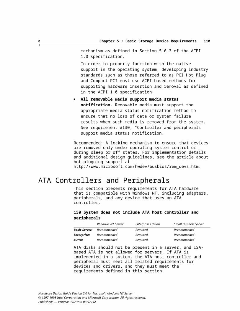
Appendix A • Server Requirements Checklist 115
125. Infrared device supports both FIR and SIRRequired
126. IrDA hardware reports a unique Plug and Play ID sufficient to support unattended driver installationRequired
Storage Device Requirements127. Non-ISA host controllers and devices support bus masteringRequired
128. System and Option ROMs support Int 13h ExtensionsRequired
129. Block rewritable optical ATAPI device complies with SFF 8070iRequired
130. Controller and peripherals support media status notificationRequired
131. Operating system recognizes the boot drive in a multiple-drive systemRequired
132. USB-based mass storage device meets design guide requirements for USBRequired
133. IEEE 1394-based mass storage meets requirementsRequired
134. System includes SCSI host controller and SCSI peripheralsWindows NT Server Enterprise Edition Small Business Server
Basic Server: Recommended Required RecommendedEnterprise: Recommended Required RecommendedSOHO: Recommended Required Recommended
135. SCSI controllers provide multi-initiator support if the controller provides external device connection capability for use as a cluster nodeRequired
136. SCSI option ROMs support virtual DMA servicesRequired
137. Bus type is clearly indicated on connectors for all adapters, peripherals, cables, and terminatorsRequired
138. Differential devices support DIFFSENS as defined in SPI standardRequired
139. Automatic termination circuit and SCSI terminators meet SCSI-3 specificationRequired
140. Terminator power is supplied to the SCSI bus, with over-current protectionRequired
141. External connector meets SCSI-2 or later specificationRequired
142. Controller and peripherals implement SCSI data protection signalRequired
143. SCSI connections use keyed and shrouded connectorsRequired
144. External devices use automatic termination, an external pluggable terminator, or an accessible on-board termination switchRequired
Hardware Design Guide Version 2.0 for Microsoft Windows NT Server© 1997-1998 Intel Corporation and Microsoft Corporation. All rights reserved. Published: — Printed: 09/23/98 03:52 PM
Appendix A • Server Requirements Checklist 116
145. Shielded device connector meets SCSI-2 or later specificationRequired
146. SCAM support is disabled by defaultRequired
147. Hardware supports the STOP/START UNIT command as defined in the SPI specificationRequired
148. STOP/START UNIT command can be used to decrease power consumptionRecommended
149. SCSI devices that support hot-plugging meet design guide requirementsRequired
150. System does not include ATA host controller and peripheralsWindows NT Server Enterprise Edition Small Business Server
Basic Server: Recommended Required RecommendedEnterprise: Recommended Required RecommendedSOHO: Recommended Required Recommended
151. ATA controller and peripherals comply ATA/ATAPI-4 standardsRequired
152. Dual ATA adapters use single FIFO with asynchronous access or dual FIFOs and channelsRequired
153. System BIOS and devices support LBA if system uses ATARequired
154. System BIOS supports ARMDRecommended
155. ATA controller and peripherals support Ultra-DMARequired
156. ATA controller and peripheral connections include Pin 1 cable designation with keyed and shrouded connectorsRequired
157. ATAPI peripherals comply with ATA/ATAPI-4Required
158. BIOS enumeration of all ATAPI devices complies with ATA/ATAPI-4Required
159. ATAPI devices support DEVICE RESET commandRequired
160. ISA address ranges 3F7h and 377h are not claimed by ATA controllersRequired
161. ATA/ATAPI device supports ATA STANDBY commandRequired
162. System includes Fibre Channel controller and peripheralsWindows NT Server Enterprise Edition Small Business Server
Basic Server: Recommended Recommended RecommendedEnterprise: Recommended Recommended RecommendedSOHO: Optional Optional Optional
163. SCSI erasable drives support SCSI commandsRequired
164. System includes CD drive or other method for installing the operating systemRequired
Hardware Design Guide Version 2.0 for Microsoft Windows NT Server© 1997-1998 Intel Corporation and Microsoft Corporation. All rights reserved. Published: — Printed: 09/23/98 03:52 PM
Appendix A • Server Requirements Checklist 117
165. CD drive provides 8x or higher performanceRequired
166. CD drive is CD-Enhanced compatibleRequired
167. CD drive supports specified logical and physical CD formatsRequired
168. ATA/ATAPI CD drive complies with SFF-8020i, v. 2.6Required
169. CD drive supports multisession and compatibility forms of the READ_TOC commandRequired
170. ATA/ATAPI CD changer meets MMC-2 standardRequired
171. System BIOS or option ROM supports El Torito No Emulation modeRequired
172. CD drive uses push-to-close designRecommended
173. DVD device provides 2x minimum transfer rate or better performance anywhere on the diskRequired
174. DVD drive and controller support bus master DMA transfersRequired
175. DVD drive meets minimum compatibility requirementsRequired
176. DVD drive meets MMC-2 standardRequired
177. DVD drive uses push-to-close designRecommended
178. DVD drive supports defect managementRequired
179. System meets video playback requirements if DVD drive supports DVD-Video playbackRequired
180. System includes tape drive for local backupRecommended
181. Single-tape device meets minimum capacity requirementsWindows NT Server Enterprise Edition Small Business Server
Basic Server: 4 GB required 4 GB required 4 GB requiredEnterprise: 8 GB required 8 GB required 8 GB requiredSOHO: 4 GB required 4 GB required 4 GB required
182. Single-tape device meets minimum speed requirements20 MB/minute required
183. Tape device meets industry standardsRequired
184. SCSI tape drive supports SCSI commandsRequired
185. Win32-based backup solution provided with deviceRequired
Hardware Design Guide Version 2.0 for Microsoft Windows NT Server© 1997-1998 Intel Corporation and Microsoft Corporation. All rights reserved. Published: — Printed: 09/23/98 03:52 PM
Appendix A • Server Requirements Checklist 118
186. CD changer for seven or fewer discs meets MMC-2 standardRecommended
187. SCSI changer and drive support auto-configurationRequired
188. SCSI tape and optical disk changers support SCSI commandsRequired
Physical Design and Hardware Security Requirements189. Icons are provided for all external connectorsRequired
190. All expansion slots in the system are accessible for users to insert cardsRequired
191. System and device design include protected switchesRecommended
192. System design includes locking caseRecommended
193. System and device design include positive retention connectorsRecommended
194. Parallel port design provides sufficient space for connector assemblyRequired
195. C2 evaluation for hardwareRecommended
196. Peripherals meet hardware security recommendationsRecommended
Reliability, Availability, and Serviceability Requirements197. System includes integrated backup solutionRecommended
198. System includes UPS provided with systemRecommended
199. System includes power supply protection using N+1 (extra unit)Windows NT Server Enterprise Edition Small Business Server
Basic Server: Recommended Recommended RecommendedEnterprise: Recommended Required RecommendedSOHO: Recommended Recommended Recommended
200. System supports replacement of power suppliesWindows NT Server Enterprise Edition Small Business Server
Basic Server: Recommended Required RecommendedEnterprise: Required Required RequiredSOHO: Recommended Required Recommended
201. System supports replacement of fansWindows NT Server Enterprise Edition Small Business Server
Basic Server: Optional Required OptionalEnterprise: Recommended Required RecommendedSOHO: Optional Required Optional
Hardware Design Guide Version 2.0 for Microsoft Windows NT Server© 1997-1998 Intel Corporation and Microsoft Corporation. All rights reserved. Published: — Printed: 09/23/98 03:52 PM
Appendix A • Server Requirements Checklist 119
202. System includes local hot-swap power supply replacement indicatorsWindows NT Server Enterprise Edition Small Business Server
Basic Server: Recommended Required RecommendedEnterprise: Recommended Required RecommendedSOHO: Recommended Required Recommended
203. System includes multiple hard drivesWindows NT Server Enterprise Edition Small Business Server
Basic Server: Recommended Required RecommendedEnterprise: Recommended Required RecommendedSOHO: Recommended Required Recommended
204. System includes intelligent RAID controller with adequate storage capacityWindows NT Server Enterprise Edition Small Business Server
Basic Server: Recommended Required RecommendedEnterprise: Required Required RequiredSOHO: Optional Required Optional
205. System supports at least one of RAID 1, 5, or 1/0Windows NT Server Enterprise Edition Small Business Server
Basic Server: Recommended Required RecommendedEnterprise: Required Required RequiredSOHO: Recommended Required Recommended
206. RAID support includes notification of failed driveRequired
207. RAID subsystem supports automatic replacement of failed driveWindows NT Server Enterprise Edition Small Business Server
Basic Server: Required Required RequiredEnterprise: Required Required RequiredSOHO: Recommended Required Recommended
208. RAID subsystem supports manual replacement of failed driveWindows NT Server Enterprise Edition Small Business Server
Basic Server: Recommended Required RecommendedEnterprise: Required Required RequiredSOHO: Recommended Required Recommended
209. System includes protected forced NMI switch for system diagnosisRecommended
210. System includes alert indicators for occurrence of failureWindows NT Server Enterprise Edition Small Business Server
Basic Server: Recommended Required RecommendedEnterprise: Recommended Required RecommendedSOHO: Recommended Required Recommended
211. Hot-swappable drive includes a local disk drive replacement indicatorRequired
212. System includes alert indicators for imminence of failureWindows NT Server Enterprise Edition Small Business Server
Basic Server: Recommended Required RecommendedEnterprise: Recommended Required RecommendedSOHO: Recommended Required Recommended
Hardware Design Guide Version 2.0 for Microsoft Windows NT Server© 1997-1998 Intel Corporation and Microsoft Corporation. All rights reserved. Published: — Printed: 09/23/98 03:52 PM
Appendix A • Server Requirements Checklist 120
213. Remote new system setup and service boot support uses DHCP and TFTPRecommended
214. Expansion devices can be remotely managedRecommended
215. System supports Windows hardware instrumentation implementation guidelinesRequired
216. System includes driver support for WMIRequired
217. Management information service provider enabled by defaultRequired
218. SMBIOS 2.1 or later static table support providedRecommended
Hardware Design Guide Version 2.0 for Microsoft Windows NT Server© 1997-1998 Intel Corporation and Microsoft Corporation. All rights reserved. Published: — Printed: 09/23/98 03:52 PM
121
See also the Hardware Glossary available on http://www.microsoft.com/hwdev/glossary.htm.
Acronyms and AbbreviationsABR available bit rate
ACE access control entry
ACPI Advanced Configuration and Power Interface
ADA Americans with Disabilities Act
ADSL Asymmetric Digital Subscriber Line
ANSI American National Standards Institute
API application programming interface
APIC Advanced Programmable Interrupt Controller
ARC Advanced RISC Computing
ASCII American Standard Code for Information Interchange
ASIC application-specific integrated circuit
AT IBM registered trademark for PC/AT
ATA AT Attachment
ATAPI ATA Packet Interface
ATM asynchronous transfer mode
BAR base address register
BDA BIOS Data Area
BIOS basic I/O system
bps bits per second
CBR constant bit rate
CHAP challenge handshake authentication protocol
CID Compatible ID
CIM Common Information Model
CISC complex instructions set computers
CMOS complementary metal-oxide semiconductor
COM 1. Component Object Model; 2. legacy serial port.
CSS copy scramble system
DAC digital-to-analog converter
DCE Data Communications Equipment
DDK device driver kit
DHCP Dynamic Host Configuration Protocol
DLL dynamic link library
DMA direct memory access
DMI Desktop Management Interface
DMTF Desktop Management Task Force
DSVD digital simultaneous voice/data
ECC error correction code
ECP extended capabilities port
EDT European Deaf Telephone
EIDE Enhanced Integrated Device Electronics
EISA extended ISA
EPP enhanced parallel port
Hardware Design Guide Version 2.0 for Microsoft Windows NT Server© 1997-1998 Intel Corporation and Microsoft Corporation. All rights reserved. Published: July 22, 1998 — Printed: 09/23/98 03:52 PM
Glossary
Glossary 122
ESCD Extended System Configuration Data
ETSI European Telecommunications Standards Institute
FCD floppy disk controller
FC-PH Fibre Channel Physical, Revision 4.3
FIFO first in/first out
FSK Frequency Shift Keyed
GB gigabyte
GSM global system for mobile communications
HAL hardware abstraction layer
HCL Hardware Compatibility List
HCT Hardware Compatibility Tests
HDLC high-level data link control
HID Human Interface Device
HMMP HyperMedia Management Protocol
HSM hierarchical storage management
Hz Hertz
IDE Integrated Device Electronics
IEEE Institute of Electrical and Electronics Engineers
IETF Internet Engineering Task Force
IHV independent hardware vendor
I/O input/output
IOCTL I/O control
IP Internet Protocol
IPX/SPX Internetwork Packet Exchange/Sequenced Packet Exchange protocol
IRP I/O request packet
IRQ interrupt request
ISA Industry Standard Architecture
ISDN Integrated Service Digital Network
I2O Intelligent I/O
ITU International Telecommunications Union
LAN local area network
LBA logical block addressing
LED light-emitting diode
LPT line printer
LSI large-scale integration
L2 Level 2
LUN logical unit number
MAC Media Access Control
MB megabyte
Mb/s megabits per second
MSCS Microsoft Cluster Server
MDK Modem Developers Kit
MEI Matsushita Electronics Incorporated
ms millisecond
MSDN Microsoft Developer Network
NCSC National Computer Security Center
NDIS Network Driver Interface Specification
NetBEUI NetBIOS Extended User Interface
NIUF National ISDN User’s Forum
NMI Nonmaskable Interrupt
NTMS Windows NT Media Services
OAM operation and maintenance
OEM original equipment manufacturer
OpenHCI Open Host Controller Interface
OSI Open System Interface
PCI Peripheral Component Interconnect
PCI 2.1 PCI Local Bus Specification, Revision 2.1
PCM pulse coded modulation
PIO programmed I/O
PLDA Private Loop Direct Attach
POST power-on self-test
PPP point-to-point protocol
PS/2 Personal System/2
PTT Post, Telephone, and Telegraph
QIC Quarter-Inch Cartridge
QoS Quality of Service
Hardware Design Guide Version 2.0 for Microsoft Windows NT Server © 1997-1998 Intel Corporation and Microsoft Corporation. All rights reserved. Published: July 22, 1998 — Printed: 09/23/98 03:52 PM
Glossary 123
RADSL rate adaptive digital subscriber line
RAID retrieval and information database
RAM random access memory
RFC Request for Comments
RISC reduced instruction set computing
ROM read-only memory
rt real time
SCSI small computer system interface
SDK software developers kit
SFF Small Form Factor
SIG Special Interest Group
SMART Self-Monitoring, Analysis, and Reporting Technology
SMP symmetric multiprocessing
SNMP Simple Network Management Protocol
SOHO small office/home office
SPID service profile identifier
STS/EN Status and Enable bits (ACPI)
SVGA Super VGA
TAPI Telephony Application Program Interface
TB terabyte
TCO total cost of ownership
TCP/IP Transmission Control Protocol/ Internet Protocol
TDD Telephone Device for the Deaf
TFTP Trivial File Transfer Protocol
UART Universal Asynchronous Receiver/Transmitter
UBR unspecified bit rate
UDF universal disk format
UHCI Universal Host Controller Interface
Unimodem universal modem driver
UPS uninterruptible power supply
USB Universal Serial Bus
VAR value-added retailer
VBR variable bit rate
VC virtual channel
VCI virtual channel identifier
VDM virtual device manager
VGA video graphics array
VPI virtual path identifier
WBEM Web-Based Enterprise Management
WDL Windows Driver Library
WDM Windows Driver Model
WfM Wired for Management
WHQL Windows Hardware Quality Laboratory
WMI Windows Management Instrumentation
Hardware GlossaryAACPI Advanced Configuration and Power Inter-face. A specification that defines a new interface to the system board that enables the operating system to implement operating system–directed power management and system configuration. Following the ACPI allows system manufacturers to build systems consistent with the OnNow design initiative for instantly available PCs.
ACPI hardware Computer hardware with the features necessary to support operating system power management and with the interfaces to those features described using the Description Tables as specified in Advanced Configuration and Power Interface Specification.
add-on devices Devices that are traditionally added to the base system to increase functionality, such as audio, networking, graphics, SCSI con-troller, and so on. Add-on devices fall into two categories: devices built onto the system board and devices on expansion cards added to the system through a system board connector such as PCI.
ADSL Asymmetric Digital Subscriber Line. A method for moving data over regular phone lines. An ADSL circuit is much faster than a regular phone connection, and the wires coming into the subscriber’s premises are the same (copper) wires used for regular phone service.
Hardware Design Guide Version 2.0 for Microsoft Windows NT Server © 1997-1998 Intel Corporation and Microsoft Corporation. All rights reserved. Published: July 22, 1998 — Printed: 09/23/98 03:52 PM
Glossary 124
API Application programming interface. A set of routines that an applications program uses to request and carry out lower-level services performed by a computer operating system.
architecture A general term referring to the structure of all or part of a computer system. Also covers the design of system software, such as the operating system, as well as referring to the combination of hardware and basic software that links machines on a computer network.
ATA AT Attachment. An integrated bus usually used between host processors and disk drives. Used interchangeably with IDE.
ATAPI ATA Packet Interface. A hardware and software specification that documents the interface between a host computer and CD-ROM drives using the ATA bus.
ATM Asynchronous transfer mode. A transmission protocol that segments user traffic into small, fixed-size units called cells, which are transmitted to their destination, where they are reassembled into the original traffic. During transmission, cells from different users may be intermixed asynchronously to maximize utilization of network resources.
Bbandwidth Usually used in reference to the amount of data per unit of time that must move from one point to another, such as from CD-ROM to processor.
BIOS Basic I/O system. A set of routines that works closely with the hardware to support the transfer of information between elements of the system, such as memory, disks, and the monitor. Although critical to performance, the BIOS is usually invisible to the end user; however, programmers can access it.
bps Bits per second. The number of bits transferred per second in a data communications system. A measure of speed.
bus enumerator In a Plug and Play system, a bus device driver that detects devices located on a specific bus and loads information about devices into the hardware tree.
Ccache A special memory subsystem in which frequently used data values are duplicated for quick access.
CD-ROM Compact disc read-only memory. A 4.75-inch laser-encoded optical memory storage medium (developed by NV Philips and Sony Corporation) with the same constant linear velocity (CLV) spiral format as compact audio discs and some video discs. CD-ROM discs can hold about 550 MB of data.
CI Component Instrumentation. A specification for DMI related to the service layer.
class For hardware, the manner in which devices and buses are grouped for purposes of installing and managing device drivers and allocating resources.
class driver A driver that provides system-required, hardware-independent support for a given class of physical devices. Such a driver communicates with a corresponding hardware-dependent port driver, using a set of system-defined device control requests, possibly with additional driver-defined device control requests. Under WDM, the class driver is responsible for multiprocessor and interrupt synchronization.
COM 1. Component Object Model; the core of OLE. Defines how OLE objects and their clients interact within processes or across process boundaries. 2. Legacy serial port.
CPU Central processing unit. A computational and control unit of a computer; the device that interprets and executes instructions. By definition, the CPU is the chip that functions as the “brain” of the computer.
Ddata rate The speed of a data transfer process, normally expressed in bits per second or bytes per second.
DDC Display data channel. The Plug and Play baseline for monitors. The communications channel between a monitor and the display adapter to which it is connected. This channel provides a method for the monitor to convey its identity to the display adapter.
Hardware Design Guide Version 2.0 for Microsoft Windows NT Server © 1997-1998 Intel Corporation and Microsoft Corporation. All rights reserved. Published: July 22, 1998 — Printed: 09/23/98 03:52 PM
Glossary 125
device Any circuit that performs a specific function, such as a parallel port.
device ID A unique ASCII string for a device created by enumerators to identify a hardware device and used to cross-reference data about the device stored in the registry. Distinguishes each logical device and bus from all others on the system.
disk I/O controller Also HDC. A special-purpose chip and circuitry that directs and controls reading from and writing to a computer’s disk drive.
DLL Dynamic link library. API routines that User-mode applications access through ordinary procedure calls. The code for the API routine is not included in the user’s executable image. Instead, the operating system automatically points the executable image to the DLL procedures at run time.
DMA Direct memory access. A method of moving data from a device to memory (or vice versa) without the help of the microprocessor. The system board uses a DMA controller to handle a fixed number of channels, each of which can be used by only one device at a time.
DMI Desktop Management Interface. A framework created by the DMTF. DMTF specifications define industry-standard interfaces for instrumentation providers and management applications.
driver Kernel-mode code used either to control or emulate a hardware device.
driver stack Device objects that forward IRPs to other device objects. Stacking always occurs from the bottom up and is torn down from the top.
DVD Optical disk storage that encompasses audio, video, and computer data.
EECP Extended capabilities port. An asynchronous, 8-bit–wide parallel channel defined by IEEE 1284–1944 that provides PC-to-peripheral and peripheral-to-PC data transfers.
EISA Extended Industry Standard Architecture. A 32-bit expansion bus designed as a superset of the ISA bus. Designed to expand the speed and data width of the legacy expansion bus while still supporting older ISA cards.
enumerator A Plug and Play device driver that detects devices below its own device node, creates unique device IDs, and reports to Configuration Manager during startup. For example, a SCSI adapter provides a SCSI enumerator that detects devices on the SCSI bus.
expansion bus A group of control lines that provide a buffered interface to devices located either on the system board or on cards that are plugged into expansion connectors. Common expansion buses included on the system board are USB, PC Card, and PCI.
expansion card A card that connects to an expansion bus and contains one or more devices.
expansion ROM See option ROM.
FFDC Floppy disk controller. A chip and associated circuitry that directs and controls reading from and writing to a computer’s disk drive.
FIFO First in/first out. A method for processing a queue in which items are removed in the same order they were added.
filters 1. Components that provide the basic building blocks for processing data. 2. Under the WDM Stream architecture filters are also known as a functional device or multimedia processing driver. Each filter’s capability is described in part by connection points called pins. Each pin can consume and produce a data stream, such as digital audio. Specialized tasks can be solved by connecting filters through their pins into a topology, for example, to play filtered and mixed audio. 3. Under WDM, a filter is implemented as a kernel-mode entity—a device object usually implemented by a kernel driver. 4. Under ActiveMovie, a filter is a User-mode entity that is an instance of a COM object, usually implemented by a DLL.
full duplex In terms of data flow, indicates bi-directional data flow.
HHCI Host controller interface, such as the system-level interface supporting USB.
HCL Hardware Compatibility List. See WHQL.
Hardware Design Guide Version 2.0 for Microsoft Windows NT Server © 1997-1998 Intel Corporation and Microsoft Corporation. All rights reserved. Published: July 22, 1998 — Printed: 09/23/98 03:52 PM
Glossary 126
HCT Hardware Compatibility Tests. A suite of tests from WHQL to verify hardware and device driver operations under a specific operating environment. These tests exercise the combination of a device, a software driver, and an operating system under controlled conditions to verify that all components operate properly.
IIDE Integrated Device Electronics. A type of disk-drive interface where the controller electronics reside on the drive itself, eliminating the need for a separate adapter card.
IEEE Institute of Electrical and Electronics Engineers. Organization that develops standards.
INF file Information file. A file created for a particular adapter that provides the operating system with information required to set up a device, such as a list of valid logical configurations for the device, the names of driver files associated with the device, and so on. An INF file is typically provided by the device manufacturer on a disk with an adapter.
INI file Initialization file. Commonly used under Windows 3.x and earlier, INI files have been used by both the operating system and individual appli-cations to store persistent settings related to an application, driver, or piece of hardware. In Windows NT and Windows 95, INI files are supported for backward compatibility, but the registry is the preferred location for storing such settings.
input class The class of filters that provides an interface for HID hardware, including USB and legacy devices, plus proprietary and other HID hardware, under the WDM HID architecture.
instrumentation A mechanism for reporting information about the state of hardware and software to enable management applications to ascertain and change the state of a system and to be notified of state changes.
integrated device Any device—such as a parallel port or graphics adapter—that is designed on the system board rather than on an expansion card.
interface For parameters on a connection request, a specific set of methods and properties imple-mented on a medium that a filter connection uses to communicate, such as a specific set of IOCTLs.
I/O Input/output. Two of the three activities that characterize a computer (input, processing, and output). Refers to the complementary tasks of gathering data for the microprocessor to work with and make the results available to the user through a device such as the display, disk drive, or printer.
IOCTL Input/output control. A custom class of IRPs available to User mode. Each WDM class driver has a set of IOCTLs that it uses to communi-cate with applications. The IOCTLs give the class driver information about intended usage by applications. The class driver performs all IOCTL parameter validation.
IPL Initial program load. A device used by the system during the boot process to load an operating system into memory.
IRP I/O request packet. Data structures that drivers use to communicate with each other. The basic method of communication between kernel-mode devices. An IRP is a key data structure for WDM, which features multiple layered drivers. In WDM, every I/O request is represented by an IRP that is passed from one driver layer to another until the request is complete. When a driver receives an IRP, it performs the operation the IRP specifies, and then either passes the IRP back to the I/O Manager for disposal or onto an adjacent driver layer. An IRP packet consists of two parts: a header and the I/O stack locations.
IRQ Interrupt request. A method by which a device can request to be serviced by the device’s software driver. The system board uses a PIC to monitor the priority of the requests from all devices. When a request occurs, a microprocessor suspends the current operation and gives control to the device driver associated with the interrupt number issued. The lower the number—for example, IRQ3—the higher the priority of the interrupt. Many devices only support raising requests of specific numbers.
ISA Industry Standard Architecture. An 8-bit (and later, a 16-bit) expansion bus that provides a buffered interface from devices on expansion cards to the internal bus.
ISDN Integrated Service Digital Network. A set of communications standards that enable a single phone line or optical cable to carry voice, digital network services, and video.
Hardware Design Guide Version 2.0 for Microsoft Windows NT Server © 1997-1998 Intel Corporation and Microsoft Corporation. All rights reserved. Published: July 22, 1998 — Printed: 09/23/98 03:52 PM
Glossary 127
isochronous Refers to a communication protocol based on time slices rather than handshaking. For example, a process might have 20 percent of total bus bandwidth. During its time slice, the process can stream data.
Kkernel The core of the layered architecture that manages the most basic operations of the operating system, such as sharing the processor between different blocks of executing code, handling hardware exceptions, and other hardware-dependent functions.
kernel mode The processor mode that allows full, unprotected access to the system. A driver or thread running in kernel mode has access to system memory and hardware.
kernel-mode driver Driver for a logical, virtual, or physical devices.
LLAN Local area network. A group of computers and other devices dispersed over a relatively limited area and connected by a communications link that enables any device to interact with any other device on the network. Compare with WAN.
layered driver One of a collection of drivers that responds to the same IRPs. Layered driver describes the highest- and lowest-level drivers in a chain of layered drivers that process the same IRPs, along with all intermediate drivers in the chain.
legacy Any feature in the system based on older technology for which compatibility continues to be maintained in other system components.
local bus Usually refers to a system bus directly connected to the microprocessors on a system board. Used colloquially to refer to system board buses that are located closer to the microprocessor than expansion buses (that is, with less buffering), which are therefore capable of greater throughput.
MMDL Memory descriptor list. In Windows NT, an opaque structure, defined by Memory Manager, that uses an array of physical page frame numbers to describe the pages that back a virtual memory range.
minidriver A hardware-specific DLL that uses a Microsoft-provided class driver to accomplish most actions through functions call and provides only device-specific controls. Under WDM, the minidriver uses the class driver’s device object to make system calls.
miniport driver A device-specific kernel-mode driver linked to a Windows NT or WDM port driver, usually implemented as a DLL that provides an interface between the port driver and the system.
monolithic driver A driver that has many different classes of functionality contained in the same driver.
motherboard See system board.
multifunction device A piece of hardware that supports multiple, discrete functions, such as audio, mixer, and music, on a single adapter.
NNDIS Network Driver Interface Specification. The interface for network drivers used in Windows NT and Windows. NDIS provides transport indepen-dence for network vendors because all transport drivers call the NDIS interface to access the network.
nibble mode An asynchronous, peripheral-to-host channel defined in the IEEE 1284-1944 standard. Provides a channel for the peripheral to send data to the host, which is commonly used as a means of identifying the peripheral.
NMI Nonmaskable Interrupt. An interrupt that cannot be overruled by another service request. A hardware interrupt is called nonmaskable if it cannot be masked by the processor’s interrupt enable flag.
NTFS Windows NT file system. An advanced file system designed for use specifically with the Windows NT operating system. NTFS supports file system recovery and extremely large storage media, in addition to other advantages.
Hardware Design Guide Version 2.0 for Microsoft Windows NT Server © 1997-1998 Intel Corporation and Microsoft Corporation. All rights reserved. Published: July 22, 1998 — Printed: 09/23/98 03:52 PM
Glossary 128
OOEM Original equipment manufacturer. Used primarily to refer to systems manufacturers.
OnNow A design initiative that seeks to create all the components required for a comprehensive, system-wide approach to system and device power control. OnNow is a term for a system that is always on but appears off and that responds immediately to user or other requests.
option ROM Optional read-only memory found on an expansion card. Option ROMs usually contain additional firmware required to properly boot the peripheral connected to the expansion card, for example, a hard drive.
PPCI Peripheral Component Interconnect. A 32-bit or 64-bit bus designed to be used with devices that have high bandwidth requirements, such as the display subsystem.
planar See system board.
Plug and Play A design philosophy and set of specifications that describe hardware and software changes to the system and its peripherals that automatically identify and arbitrate resource requirements among all devices and buses on the system. Plug and Play specifies a set of device driver interface elements that are used in addition to, not in place of, existing driver architectures.
port A connection or socket used to connect a device—such as a printer, monitor, or modem— to the computer. Information is sent from the computer to the device through a cable.
port driver A low-level driver that responds to a set of system-defined device control requests and possibly to an additional set of driver-defined (private) device control requests sent down by a
corresponding class driver. A port driver insulates class drivers from the specifics of host bus adapters and synchronizes operations for all its class drivers.
port replicator Low-cost docking-station substitute intended to provide convenient, one-step connection to multiple desktop devices.
POST Power-on self-test. A procedure of the system BIOS that identifies, tests, and configures the system in preparation for loading the operating system.
power management Mechanisms in software and hardware to minimize system power consumption, manage system thermal limits, and maximize system battery life. Power management involves trade-offs among system speed, noise, battery life, processing speed, and power consumption.
QQIC Quarter-Inch Cartridge Drive Standards, Inc. An international trade association dedicated to promoting use of quarter-inch tape technology and products. For more information, visit the web site at http://www.qic.org/.
RRAM Random access memory. Semiconductor-based memory that can be read and written by the microprocessor or other hardware devices. Refers to volatile memory, which can be written as well as read.
real-time processing Processing that supports real-time functions such as telephony.
registry In Windows NT and Windows, the tree-structured hierarchical database where general system hardware and software settings are stored. The registry supersedes the use of separate INI files for all system components and applications that know how to store values in the registry.
resource 1. A set from which a subset can be allocated for use by a client, such as memory or bus bandwidth. This is not the same as resources that are allocated by Plug and Play. 2. A general term that refers to IRQ signals, DMA channels, I/O port addresses, and memory addresses for Plug and Play.
Hardware Design Guide Version 2.0 for Microsoft Windows NT Server © 1997-1998 Intel Corporation and Microsoft Corporation. All rights reserved. Published: July 22, 1998 — Printed: 09/23/98 03:52 PM
Glossary 129
RISC Reduced instruction set computing. A type of microprocessor design that focuses on rapid and efficient processing of a relatively small set of instructions. RISC architecture limits the number of instructions that are built into the microprocessor, but optimizes each so it can be carried out very rapidly—usually within a single clock cycle.
RISC-based Refers to computers based on Windows NT–compatible implementations of RISC processors (specifically DEC Alpha).
rt Real time. In computing, refers to an operating mode under which data is received and processed; the results are returned instantaneously.
Sscalability 1. Ability of a system to take advantage of multiple processors. 2. The ability to vary the information content of a program by changing the amount of data that is stored, transmitted, or displayed. 3. In a video image, this translates to creating larger or smaller windows of video on screen (shrinking effect).
SCSI Small computer system interface. Pronounced “scuzzy.” An I/O bus designed as a method for connecting several classes of peripherals to a host system without requiring modifications to generic hardware and software.
smart card A small electronic device about the size of a credit card that contains an embedded integrated circuit. Smart cards are used for a variety of purposes, including storing medical records, storing digital cash, and generating network IDs.
software device A filter in kernel streaming and ActiveMovie that has no underlying hardware associated with it.
spin down A power-management capability in which a hard drive shuts down its spindle motor.
static resources Device resources, such as IRQ signals, DMA channels, I/O port addresses, and memory addresses, that cannot be configured or relocated.
stream An object representing an entity on an adapter capable of receiving, processing, or supplying data. Notice that a stream is identical to
a WDM Stream architecture pin. A stream can accept data from or supply data to the processor, such as a stream representing an MPEG input, or can simply route data through hardware, such as a stream representing an NTSC output jack on the back of an adapter. The purpose of representing non-data hardware with a stream is that the properties of the hardware can be controlled by software.
SVGA Super VGA. A video standard established by VESA to provide high-resolution color display on IBM-compatible computers.
system board Also motherboard or planar. The primary circuit board in a system that contains most of the basic components of the system.
system devices Devices on the system board, such as interrupt controllers, keyboard controller, real-time clock, DMA page registers, DMA controllers, memory controllers, FDC, ATA ports, serial and parallel ports, PCI bridges, and so on. In today’s systems, these devices are typically integrated in the supporting chip set.
TTAPI Telephony Application Program Interface. A set of Win32-based calls that applications use to control modems and telephones by routing application function calls to the appropriate service provider DLL for a modem.
TCP/IP Transport control protocol/interface program. A software protocol developed by the Department of Defense for communications between computers.
telephony Telephone technology.
UUART Universal Asynchronous Receiver/ Transmitter. A module composed of a circuit that contains both the receiving and transmitting circuits required for asynchronous serial communication.
Unimodem Universal modem driver. A driver-level component that uses modem description files to control its interaction with the communications driver, VCOMM.
Hardware Design Guide Version 2.0 for Microsoft Windows NT Server © 1997-1998 Intel Corporation and Microsoft Corporation. All rights reserved. Published: July 22, 1998 — Printed: 09/23/98 03:52 PM
Glossary 130
UPS Uninterruptible power supply. A device connected between a computer and a power source that ensures that electrical flow to the computer is not interrupted because of a blackout and, in most cases, protects the computer against potentially damaging events such as power surges and brownouts.
USB Universal Serial Bus. A bi-directional, isochronous, dynamically attachable serial interface for adding peripheral devices such as game controllers, serial and parallel ports, and input devices on a single bus.
USB class The class of filters under WDM that provides a bus interface and bus enumerator for USB.
user mode The nonprivileged processor mode in which application code executes, including protected subsystem code in Windows NT.
user-mode drivers Win32-based multimedia drivers and VDDs for MS-DOS–based applications with application-dedicated devices. For information, see the Multimedia Drivers and Virtual DOS Drivers documentation in the Windows NT DDK.
VVAR Value added reseller. A company that resells hardware and software packages to developers and/or end users.
VESA Video Electronics Standards Association. A governing body that establishes standards for the video and graphics portions of the electronics industry.
WWAN Wide area network. A communications network that connects geographically separated areas. Compare with LAN.
WBEM Web-based Enterprise Management. A DMTF initiative to provide a standards-based mechanism to specify information exchange between management applications and managed components. This work was recently transferred to the DMTF by BMC Software, Inc., Cisco Systems, Inc., Compaq Computer Corporation, Intel Corporation, and Microsoft Corporation.
WDL Windows NT Driver Library. See WHQL.
WDM Windows Driver Model. A 32-bit driver model based on the Windows NT driver model that is designed to provide a common architecture of I/O services and binary-compatible device drivers for both Windows NT and Windows operating systems for specific classes of drivers. These driver classes include USB and IEEE 1394 buses, audio, still-image capture, video capture, and HID-compliant devices such as USB mice, keyboards, and joysticks. Provides a model for writing kernel-mode drivers and minidrivers, and provides extensions for Plug and Play and power management.
WHQL Windows Hardware Quality Labs. Provides testing services for hardware and drivers for Windows and Windows NT. Administers test-ing for the “Designed for Microsoft Windows” logo programs. See http://www.microsoft.com/hwtest/.
Win32 API A 32-bit application programming interface for both Windows and Windows NT that includes sophisticated operating system capabilities, security, and API routines for Windows-based applications.
Windows Management Instrumentation Extensions to WDM developed for Windows NT 5.0 and Windows to provide an operating system interface through which instrumented components can provide information and notifications.
Windows NT The Microsoft Windows NT version 5.0 operating system, including any add-on capa-bilities and later versions of the operating system.
Windows NT DDK Supports Windows NT, provided through MSDN Professional membership. Documents the Windows NT driver model (upon which WDM is based) and is an essential component for building WDM drivers.
ZZero Administration for Windows An initiative that focuses on improving Windows and Windows NT for maximum automation of administrative tasks with centralized control and maximum flexibility.
Hardware Design Guide Version 2.0 for Microsoft Windows NT Server © 1997-1998 Intel Corporation and Microsoft Corporation. All rights reserved. Published: July 22, 1998 — Printed: 09/23/98 03:52 PM
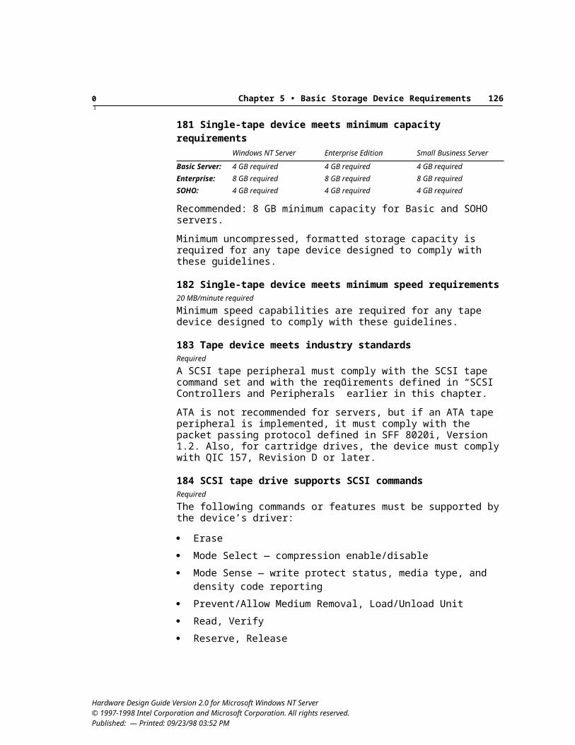
Glossary 131
2-way modems, 643.3Vaux support, 333F7h (ATA controllers), 828x CD-ROM drives, 8416-bit protected mode components, 3832-bit platforms
bus architecture, 25performance, 25, 73protected mode components, 38
64-bit platformsbus architecture, 26NT-compatible drivers, 38system memory capabilities, 13Windows NT Server support, 4
66 MHz/64-bit vs. 33MHz/32-bit PCI devices, 32377h (ATA controllers), 82802.1p/q-capable drivers, 50802.3/DIX Ethernet framing, 52, 641284 specifications. See IEEE 1284 documents and
specifications1394 specifications. See IEEE 1394 documents and
specifications1997 Version of National ISDN Basic Rate Interface
Terminal Equipment Generic Guidelines, xi8042 chip, 39
Aabbreviations for protocols and hardware, 121–123ABR service type, 60access control entry (ACE), 6accessibility
expansion slots, 96power switches, 16
ACE-compliant platforms, 6ACPI (Advanced Configuration and Power Interface).
See also OnNow design initiative; power management
Advanced Configuration and Power Interface Specification, xi, 5, 13
APIC support, 37BIOS (see BIOS)control methods and Subsystem IDs, 31defined, 123hardware insert/remove notification, 32hot-plugging support, 79hot swapping of PCI devices, 32interrupt routing, 31NT Server requirements, 13–18parallel port base address, 42Plug and Play specifications, 21routing PCI interrupts, 27sleep states, 14, 17–19system availability, 105system components and, 10Ultra-DMA support, 81
ACPI hardware, 123acronyms for protocols and hardware, 121–123Active Desktop, 49adapters. See also ATA controllers and peripherals;
network adapters; PCI (Peripheral Component Interconnect); SCSI adapters and peripherals
I2O-capable adapters, 36primary graphics adapter, 44, 90
add-on cards and devices. See also multifunction cards and devices
defined, vii, 123device IDs, 22Subsystem IDs and, 30USB compliance, 35
ADSL (Asymmetric Digital Subscriber Line) adaptersdefined, 123An Interoperable End-to-End Broadband Service
Architecture over SDSL System, xiimodem adapters, 54NT Server requirements, 62–64UBR virtual circuits and, 60–61
Hardware Design Guide Version 2.0 for Microsoft Windows NT Server © 1997-1998 Intel Corporation and Microsoft Corporation. All rights reserved. Published: July 22, 1998 — Printed: 09/23/98 03:52 PM
Index
Glossary 132
Advanced Configuration and Power Interface. See ACPI (Advanced Configuration and Power Interface)
Hardware Design Guide Version 2.0 for Microsoft Windows NT Server © 1997-1998 Intel Corporation and Microsoft Corporation. All rights reserved. Published: July 22, 1998 — Printed: 09/23/98 03:52 PM
Glossary 133
Advanced Configuration and Power Interface Specification, xi, 5, 13
Advanced RISC computing (ARC), xi, 6Advanced RISC Computing Multiprocessor Standard
Specification, xialert indicators, 105, 106analog phone connections in ISDN devices, 69–70analog VGA ports and connectors, 96. See also VGAANSI NCITS T10 Multi-Media Command Set-2
(MMC-2), 43, 75. See also MMC-2 Multi-Media Command Set-2 standard
APIC (Advanced Programmable Interrupt Controller), 12, 37
APIs (application programming interface), 124ARC (Advanced RISC computing), xi, 6architecture, 124ARC tree, parallel port addresses and, 42ARMD (ATAPI Removable Media BIOS
Specification), xii, 20–21, 81ASCII text telephones, 57asset numbers, 22Asymmetric Digital Subscriber Line. See ADSL
(Asymmetric Digital Subscriber Line) adaptersasynchronous PPP, 68asynchronous-to-synchronous conversion, 68Asynchronous Transfer Mode. See ATM
(Asynchronous Transfer Mode)ATA/ATAPI-4 Standard, xii, 29, 80ATA/ATAPI compliance, 82ATA controllers and peripherals
ATA defined, 124ATA DMA, 80, 81documents and specifications
ATA/ATAPI-4 Standard, xii, 29, 80ATA Packet Interface for CD-ROM, SFF 8020i,
xii, 85, 91ATAPI Removable Media BIOS Specification
(ARMD), xii, 20–21, 81AT Attachment 2 standard, xiiAT Attachment 3 standard, xii
DVD drives and controllers, 87media status notification, 75MMC-2 CD changer capacity, 85NT Server requirements, 80–83PCI ATA-connected CD-ROM devices, 29tape drive compliance, 91
ATA Packet Interface. See ATAPI (ATA Packet Interface)
ATA Packet Interface for CD-ROM, SFF 8020i, xii, 85, 91
ATAPI (ATA Packet Interface)ATA/ATAPI-4 compliance, 82ATAPI bootable floppy disk drive support, 20–21ATAPI CD-ROM, xii, 85, 91BIOS recognition, 81block rewritable optical ATAPI devices, 74CD changers, 92connectors, 82defined, 124DEVICE RESET command, 82media status notification, 75SFF 8070i support, 75Ultra-DMA support, 81–82
ATAPI Removable Media BIOS Specification (ARMD), xii, 20–21, 81
ATA STANDBY command, 82AT Attachment 2 standard, xiiAT Attachment 3 standard, xiiAT command set, 54, 57, 66, 67ATM (Asynchronous Transfer Mode)
ATM/ADSL solution, 61, 63ATM User-Network Interface Specification, xiidefined, 124interface for ADSL modems, 62miniport driver requirements, 46modem adapters, 54, 61, 65NT Server requirements, 58–61PPP over ATM over ADSL, 62
ATM/ADSL solutions, 61, 63ATM modem adapters, 54, 61, 65ATM User-Network Interface Specification, xii, 59audio CD formats, 85audio DVD formats, 87audio lines and connectors, 96authentication in video playback, 88automatic device configuration. See also device
configurationACPI control methods, 13–14media changers, 93
automatic sensing of connections and transceiver types, 48
automatic termination, 77, 78. See also terminationavailability. See also fault conditions and fault
tolerance; reliabilitybasic servers, 3Enterprise servers, 3failure alert indicators, 105, 106NT Server requirements, 105–106in server design, 1SOHO servers, 3
available bit rate (ABR), 60
Hardware Design Guide Version 2.0 for Microsoft Windows NT Server © 1997-1998 Intel Corporation and Microsoft Corporation. All rights reserved. Published: July 22, 1998 — Printed: 09/23/98 03:52 PM
Glossary 134
BBackOffice Small Business Server, ix, 4backup capabilities
integrated backup solution, 102tape drives, 90–92
bandwidth, 34–35, 124bar-code readers, 93BARs (Base Address Registers), 28, 31basic NT servers. See also Enterprise servers; SOHO
serversrecommendations and requirements, 3serviceability, 3
Basic Server class defined, ixBaudot text telephones, 57B channels in ISDN connection, 67, 69BDA (BIOS Data Area), 42Bellcore National ISDN Basic Rate Interface
Terminal Equipment Generic Guidelines, xibenchmark tests, 1BIOS
ATAPI recognition, 81boot devices
ATAPI bootable floppy disk drive support, 20–21
BIOS support, 18–21CD-ROM boot support, 19IRQs, configuring, 32serial port redirection from console, 20
defined, 124E820 interface, 20El Torito No Emulation mode, 86Fast POST support, 17I2O device support, 36Information Technology Enhanced BIOS Services
for Disk Drives, xiii, 74Int 13h Extensions, 74logical block addressing (LBA), 81network adapter support, 19–20PCI interrupts, configuring, 31preboot execution environment, 19security support, 19serial ports and, 20, 41Subsystem and Subsystem Vendor IDs, 30–31system ID structure, 18–19system startup support, 18–21Ultra-DMA support, 81update support, 20USB keyboard support, 20year 2000+ date support, 10
BIOS Data Area location addresses, 42
BIOS ROM upgrade support, 20bit-level PPP, 68blacklisted and delayed number clearing in modems,
56block rewritable optical ATAPI devices, 74Blue Book format, 85, 87boot devices
ATAPI bootable floppy disk drive support, 20–21BIOS support for, 18–21CD-ROM boot support, 19IRQs, configuring, 32serial port redirection, 20
boot processboot drive recognition, 75boot time, minimizing, 17Fast POST, 17network adapter support for remote boot, 49order of precedence for boot, 19POST (power-on self test), 128preboot execution environment, 19Simple Boot Flag Specification, Version 1.0, 18
bps (bits per second), 124bridges
CPU-to-PCI bridges, 33network adapters, 48PCI-to-PCI bridges, 28, 33peer bridges, 26
buffersalignment, network adapters, 48buffer chaining, 60
buses. See also bus mastering; expansion buses, cards, and devices; ISA buses and devices; PCI (Peripheral Component Interconnect); USB (Universal Serial Bus)
bus configuration methods, ACPI compliance, 13–14
bus design requirements, 25–33bus enumerator, 124bus type labeling, 77I/O bandwidth and bus capacity, 32PCI bus power states, 33resource conflict resolution, 42serial port bus requirements, 40
bus masteringDVD-ROM devices, 87host controllers, 73–74multiple hard drives, 103PCI ATA bus master DMA, 81PCI expansion cards, 26PCI network adapters, 51
Hardware Design Guide Version 2.0 for Microsoft Windows NT Server © 1997-1998 Intel Corporation and Microsoft Corporation. All rights reserved. Published: July 22, 1998 — Printed: 09/23/98 03:52 PM
Glossary 135
bus-powered hubs, 35byte-level PPP, 68
CC2-level operating system security, 97–98cable modems
ATM/cable modem adapters, 54, 61, 65CMTS, 64MCNS documents, xiiiNT Server requirements, 64–66
cableslocking cable connections, 97plugging in incorrectly, 78SCSI requirements, 78USB icon, 34
cachesdefined, 124Error Correction Code (ECC) memory protection,
13L2 cache, 11snooping cache coherency mechanisms, 28
call manager drivers, 46call-type selection in modems, 56capacity, in server design, 2CBR connections, 60CD changers, 85, 92CD-Enhanced compatibility, 85CD-I content, 85CD-ROM devices
BIOS boot support, 19CD changers, 85, 92defined, 124media status notification, 75NT Server requirements, 84–86PCI ATA-connected CD-ROM devices, 29
CD-RW format, 87checklist of server requirements, 109–120CI (Component Instrumentation), 124CID (CompatibleID), Plug and Play compliance, 23Clarification to Plug and Play BIOS Specification, 23Clarification to Plug and Play ISA Specification, 21Class 1 and Class 2 command sets, 55CLASS description key, 43class driver, 124classes, ix, 124cleaning drives, 93clock alarm, real-time, 14closed captioning, 89cluster nodes, 76–77CMTS (cable modem termination system), 64color-coding schemes, 95–96
COM, defined, 124command sets
AT modem command set, 54, 57, 66, 67DVD-ROM devices, 87–88
Common Information Model (CIM), xi, 107, 108Compact PCI, 79Compaq, Intel, Phoenix BIOS Boot Specification
dual asynchronous channels, 80multiple- drive systems, 75network adapters boot support, 19option ROM Plug and Play capabilities, 23Web site, xii
compatibility mode, 42compatibility testing. See testingCompatibleID (CID), 23compliance dates for design requirements, xicompliance testing. See testingcomponent instrumentation, manageability
requirements, 108computer cases, locking, 97, 98configuration. See device configurationConfiguration Space. See PCI Configuration Spaceconnection ports, 34connectors
ATA/ATAPI controllers, 82color-coding, 95–96external, 95icons, 95IEEE 1284 specifications, 42, 97keyed, 78, 82, 95legacy systems, 96parallel ports, 97positive retention, 97SCSI, 78shielded, 78shrouded, 78, 82, 95
constant bit rate (CBR), 60contiguous buffers, 48controllers. See also names of specific controller
typesATA controllers and peripherals, 80–83ATAPI rewritable devices, 74bus mastering, 73–74CD-ROM devices, 84–86dual-channel, 80–81DVD-ROM devices, 86–90erasable disk drives, 83–84Fibre Channel controllers and peripherals, 83hard drive performance requirements, 73host controllers, 14–15, 34, 73–74, 76, 80Int 13h Extensions, 74
Hardware Design Guide Version 2.0 for Microsoft Windows NT Server © 1997-1998 Intel Corporation and Microsoft Corporation. All rights reserved. Published: July 22, 1998 — Printed: 09/23/98 03:52 PM
Glossary 136
controllers (continued)media. tape, and CD changers, 92–93media status notification, 75modem controllers, 57multiple hard drives, 103–104RAID controllers, 103–104SCSI controllers, 76tape drives, 90–92
copyright protection, 88copy scramble systems (CSS), 88CPE (Customer Premises Equipment), 64CPUs (central processing unit), 124custom-designed systems, viiiCustomer Premises Equipment (CPE), 64
DDAC (dual address cycle), 26Data Communications Equipment (DCE), 56, 58DATA/FAX call classification, 56data modems. See modemsData-Over-Cable Service Interface Specification, 64data protection signal (SCSI), 78data rate, 124dates, server design requirements compliance dates,
xiDAVIC, 64DBC (Device Bay Controller), 23–24, 51DCE (Data Communications Equipment), 56, 58DDC (display data channel), 124DDKs. See names of specific DDKsDEC Alpha-based systems
defined, viimicro- and multiprocessor requirements, 11parallel port base address, 42processor requirements, 6USB keyboards, 40
decode-rate adjustment in DVD devices, 88–89decoder driver in DVD devices, 88–89dedicated interrupt lines, 26–28defects and defect management. See fault conditions
and fault tolerance; reliabilitydelayed number clearing in modems, 56DESCRIPTION key, 43description tables (ACPI compliance), 13, 37deserialized miniports, 47Desktop Management Interface Specifications, xii,
125Desktop Management Task Force (DMTF), xiDevice Bay, 23–24, 51Device Bay Interface Specification, 23, 51
Device Class Power Management Specifications, xiidevice configuration. See also device drivers; device
IDs; devicesACPI compliance methods, 13–14auto-configuration support, 93dynamic configuration, 107I2O-ready systems, 36legacy serial ports, 40–41PCI Configuration Space, 29, 31performance tuning support, 49Plug and Play compliance, 21–22remote management, 107resource conflict resolution, 42storing configuration settings, 38USB devices, 34–35
device-dependent region in PCI Configuration Space, 29
device driver kits (DDKs). See names of specific DDKs
device drivers. See also device configuration; device IDs; devices
design requirements, 38driver signing program, 10erasable disk drives, 83–84file names, 38HCT compliance, 10Help files, 39installation and removal, 38microprocessor platform requirements, 6miniport drivers, 7, 46–47, 127NDIS drivers, 46–47, 50, 68network communications devices, 52OnNow design initiative, 5special parameters, 38unattended installation, 38WMI (Windows Management Instrumentation),
107, 108device IDs. See also device configuration; device
drivers; devicesadd-on devices, 22defined, 125expansion buses, 22IEEE 1284 peripherals, 42–43key values, 43multifunction cards, 22parallel port devices, 42–43Plug and Play, 22Subsystem and Subsystem Vendor IDs, 30–31system devices, 22
DEVICE RESET command, 82
Hardware Design Guide Version 2.0 for Microsoft Windows NT Server © 1997-1998 Intel Corporation and Microsoft Corporation. All rights reserved. Published: July 22, 1998 — Printed: 09/23/98 03:52 PM
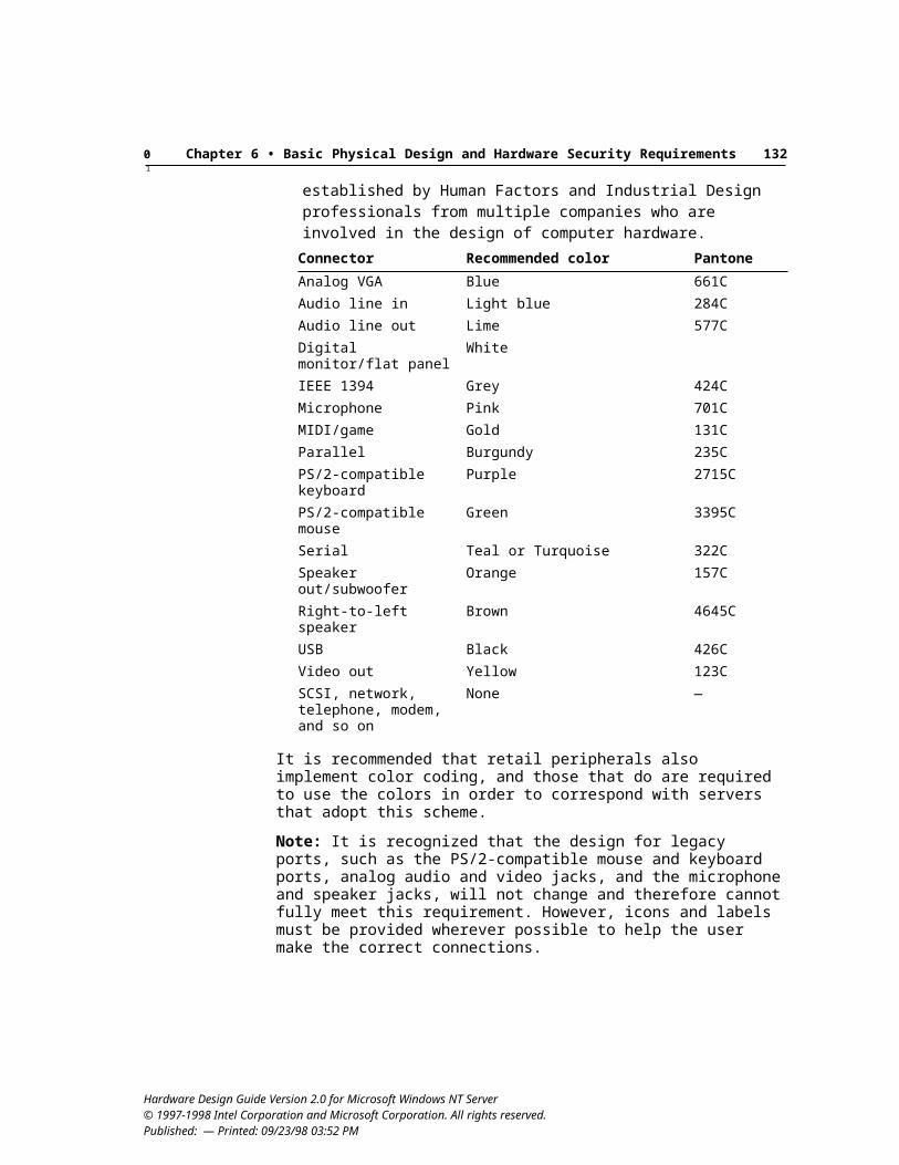
Glossary 137
devices. See also add-on cards and devices; device configuration; device drivers; device IDs; enumeration
connecting incorrectly, 78defined, 125Device Bay requirements, 23–24differential devices, 77dynamic disable capability, 14excluded from Plug and Play requirements, 21expansion devices, remote management, 107–108hot-swapping capability, 32, 103installation, design requirements, 37–39locking, 98multifunction devices, 22, 29, 36, 127
device state definitions for PCI buses, 33DIFFSENS support, 77Digital Signatures, 10digital simultaneous voice/data (DSVD), 56Digital Video Broadcasting/Digital Audio-Visual
Council, 64direct memory access. See DMA (direct memory
access)DirectShow, 58DirectX SDK, 89disable capabilities, 14, 21, 40disk drives. See drivesdisk I/O controller, 125. 126DLLs (dynamic link libraries), 125DMA (direct memory access)
ATA DMA, 80bus master DMA transfers, DVD support, 87defined, 125parallel port channel selections, 41PCI ATA bus master DMA, 81Ultra-DMA support, 29, 81–82virtual DMA services, 77
DMI Compliance Guidelines, xiiDMT line encoding, 63DOCSIS, 52, 64double word buffer alignment, 48drivers, 125. See also device driversdriver stack, 125drives. See also CD-ROM devices; DVD-ROM
devicesARMD, 81ATAPI bootable floppy disk drive support, 20–21disk I/O controller, 125, 126erasable disk drives, 83–84external drive devices, 98FDC (floppy disk controller), 125floppy disk emergency repair support, 43hard drives, 73–76, 103
IDE floppy disk drives, 43Information Technology Enhanced BIOS Services
for Disk Drives, xiii, 74magneto-optical drives, 83, 92media status notification, 75multiple hard drives, 103optical disk changers, 92–93phase-change drives, 83, 92RAID support, 103–104tape drives, 90–92
DSVD implementations, 56DTE-controlled operation in modems, 56DTMF text telephones, 57dual address cycle (DAC), 26dual ATA adapters, 80dual-channel controllers, 80–81DVB/DAVIC, 64DVD-ROM devices
DVD defined, 125DVD Specification, 88, 89DVD Specifications for Rewritable Disc, Part 1:
Physical Specifications, 88media status notification, 75NT Server requirements, 86–90
DVD+RW support, 88DVD Specification, 88, 89DVD Specifications for Rewritable Disc, Part 1:
Physical Specifications, 88DVD-Video support, 88, 89dynamic disable capabilities, 14, 21, 40Dynamic Interrupt Moderation, 49dynamic link speed configuration (ATM adapters), 61dynamic system configuration, 107
EE820 interface for reporting memory, 20ease of use in server design, 2, 3EAZ settings, 67ECC (Error Correction Code) memory protection, 13ECMA DVD formats, 87, 88ECPs (extended capabilities ports), 41, 42, 125EDT text telephones, 57EISA (Extended Industry Standard Architecture), 125El Torito—Bootable CD-ROM Format Specification,
xii, 19, 86embedded components, HCT compliance, 10emergency repair support, 43encryption, IP Security, 47
Hardware Design Guide Version 2.0 for Microsoft Windows NT Server © 1997-1998 Intel Corporation and Microsoft Corporation. All rights reserved. Published: July 22, 1998 — Printed: 09/23/98 03:52 PM
Glossary 138
Enhanced BIOS (Information Technology Enhanced BIOS Services for Disk Drives), xiii, 74
Enhanced Music CD Specification, xiii, 85enhanced parallel ports (EPP), 42Enterprise Edition, Windows NT Server, ix, 4, 26Enterprise servers
Digital Signatures, 10modem design issues, 53, 54NT Server requirements, 3–4server classes, ix
enumerationATAPI devices, 82device IDs, 22enumerators, 125hot swapping and dynamic enumeration, 32legacy devices, 23non-Plug and Play devices, 13–14resource conflicts, resolving, 42Subsystem and Subsystem Vendor IDs, 30–31
enumerators, 125EPP (enhanced parallel ports), 42erasable disk drives, 83–84error correction codes (ECC), 13ESCD (Extended System Configuration Data), 18Ethernet
Ethernet/ADSL implementations, 63Ethernet DOCSIS modems, 64, 66Ethernet network adapters, 52
European Deaf Telephones, 57European security evaluation of operating systems, 98European Telecommunication Standards Institute
(ETSI), xii, 64expansion buses, cards, and devices
defined, 125device IDs, 22expansion slot accessibility, 96ISA expansion devices, 36–37multiprocessor systems, 11–12network adapters, 48option ROMs, 22–23PCI expansion cards, 26Plug and Play expansion header, 23RAM expansion capabilities, 13remote management, 107–108
expansion ROM. See option ROMsexpansion slot accessibility, 96extended capabilities port (ECP) option, 41, 42, 125extended ISA (EISA), 125Extended System Configuration Data (ESCD) calling
interface, 18extensibility. See expansion buses, cards, and devicesexternal connectors. See connectors
external drive devices, 98
Ffailure alert indicators, 105, 106fans, 14, 103Fast POST support, 17. See also POST (power-on self
test)fault conditions and fault tolerance. See also
reliabilityDVD-ROM device defect management, 88ECC (Error Correction Code) memory protection,
13failure alert indicators, 105, 106hardware guidelines for fault tolerance, 103–104power switch overrides, 16RAID support and fault tolerance, 103–104Windows NT fault tolerance, 101
fax capability in modems, 54, 55–56F-C2, E3 ITSEC rating, 98FC-PH (Fibre Channel Physical), 83FDC (floppy disk controllers), 74, 125Fibre Channel Association, xii, 83Fibre Channel controllers and peripherals, 4, 76, 83Fibre Channel Physical (FC-PH), 83files. See also device drivers
Help files, 39INF files, 47, 53, 55, 66, 126INI files, 38, 126installed locations, 38
filters and filteringfilters, defined, 125network adapters, 48–49
FINAL EVALUATION REPORT Microsoft Windows NT Workstation and Server Version 3.5 with U.S. Service Pack 3, 98
FIR data devices, 70first in/first out (FIFO), 125floppy disk controllers (FDC), 74, 125floppy disk drives
ARMD, 81ATAPI bootable floppy disk drive support, 20–21emergency repair support, 43floppy disk controllers (FDC), 74, 125media status notification, 75
Frame Relay miniport driver requirements, 46framing methods
802.3/DIX Ethernet framing, 52, 64HDLC framing, 69
FTP sites. See Web sites and FTP addresses
Hardware Design Guide Version 2.0 for Microsoft Windows NT Server © 1997-1998 Intel Corporation and Microsoft Corporation. All rights reserved. Published: July 22, 1998 — Printed: 09/23/98 03:52 PM
Glossary 139
full duplexadapters, mode detection, 47defined, 125voice support in modems, 54
GGet Configuration command in MMC-2, 88Get Event Status command in MMC-2, 87ghost cards, 28Global Engineering Documents, xiiGSM (Global System for Mobile Communications)
standards, xii
HH.221 frames, 69H.320 calls, 69H.323 PPP support, 56H.324 video telephony, 56HAL (hardware abstraction layer), 6half-height cards, 96hard drives. See also drives
multiple, 103performance requirements, 73–76RAID support, 103–104
hardware. See also Windows NT Server design; names of specific devices
acronyms and abbreviations, 121–123fault tolerance, 101, 103–104hardware abstraction layer (HAL), 6Hardware Compatibility List (HCL), x, xiii, 9insert/remove notification mechanism, 32Intel server hardware design, xMicrosoft hardware developer information, xiMicrosoft server hardware design, xNT Server hardware initiatives, 4OnNow design initiative, 5, 15–18required features, Windows NT Server, viiisecurity recommendations, 97–99testing, x–xi, 9–10, 126Windows Hardware Instrumentation Implementa-
tion Guidelines, 97, 106, 108Windows Hardware Quality Labs (WHQL), x, xi,
130hardware abstraction layer (HAL), 6Hardware Compatibility List. See HCL (Hardware
Compatibility List)Hardware Compatibility Tests. See HCT (Hardware
Compatibility Tests)Hayes compatibility, 54
HCI (host controller interface). See also host controllers
defined, 125Open Host Controller Interface (OpenHCI) Speci-
fication, xiii, 35Universal HCI (UHCI) Specification, xiv, 35
HCL (Hardware Compatibility List)compliance requirements, 9overview, xtesting configurations, 10Web site, xiii
HCT (Hardware Compatibility Tests)compliance of embedded components, 10defined, 126overview, x
HDLC framing, 69header region in PCI Configuration Space, 29Help files, 39hierarchical storage management (HSM), 4high-level data link control (HDLC), 69high-performance components, selecting, 9, 25, 73high-performance send and receive calls, 47high-speed communications, legacy serial ports and,
40host controllers
ATA host controller, 80bus mastering, 73–74host controller interface (HCI) defined, 125non-ISA, 73–74Open Host Controller Interface (OpenHCI) Speci-
fication, xiii, 35SCSI adapter requirements, 76Universal HCI (UHCI) Specification, xiv, 35USB host controller, 14–15, 35
host-side V.90 support, 55hot-plugging support, 79hot swapping, 103
drive replacement indicators, 106multiple hard drives, 104PCI devices, 32power supplies, 102
hubs, USB requirements, 35Human Interface Device (HID), 4
II2O (Intelligent I/O) Architecture Specification, xiiI2O (Intelligent I/O) hidden devices, 4, 21, 22, 36
Hardware Design Guide Version 2.0 for Microsoft Windows NT Server © 1997-1998 Intel Corporation and Microsoft Corporation. All rights reserved. Published: July 22, 1998 — Printed: 09/23/98 03:52 PM
Glossary 140
IBM Personal System/2keyboard ports, 39mouse ports, 39port color-coding, 96
IBM Personal System/2 Common Interfaces, xiiIBM Personal System/2 mouse specifications, 39IBM Personal System/2 Mouse Technical Reference,
xiiicons
examples, Web site, 95external connectors, 95SCSI icons, 77USB icons, 34
IDE (Integrated Device Electronics), 43, 126IDs. See also device IDs
CompatibleID (CID), 22–23Subsystem and Subsystem Vendor IDs, 30–31
IEEE (Institute of Electrical and Electronics Engineers), 126
IEEE 802 documents and specificationsIEEE 802.1d, 64IEEE 802.14, 64IEEE 802-style network adapter support, 50
IEEE 1284 documents and specificationsdevice IDs, 42parallel port connectors, 97parallel ports, 41, 42
IEEE 1394 documents and specifications1394 Open Host Controller Interface Specifica-
tion, 76color-coding ports and connectors, 96Device Bay requirements, 24miniport drivers for network adapters, 46network adapters, 51obtaining standards, xiiOnNow design initiative support, 5, 15Windows NT Server support, 4
IEEE 1394 storage devicesmedia status notification, 75NT Server requirements, 76
IETF Integrated Services, 50ILMI line rate queries, 61imminent failure alerts, 106Industry Standard Architecture. See ISA buses and
devicesINF files
defined, 126ISDN devices, 66miniport driver requirements, 47reducing need for, 55Unimodem INF files, 53
Information Technology Enhanced BIOS Services for Disk Drives, xiii, 74
informative failure alerts, 106infrared devices, 70–71Infrared Extensions to the NDIS Version 4.0
Functional Specification, 70INI files, 38, 126input class, 126input/output. See I/O (input/output) devicesinstallation
network adapter support for remote setup, 49operating systems and CD-ROM drives, 84requirements, 37–39
installed system memory. See memoryInstantly Available PC System Power Delivery
Requirements and Recommendations, 17Institute of Electrical and Electronics Engineers. See
IEEE entriesinstrumentation, 108, 126Int 13h Extensions, 21, 74, 81Int 40h Extensions, 21, 74Integrated Device Electronics (IDE), 43, 126integrated devices, 126Integrated Service Digital Network. See ISDN devicesIntel Architecture
defined, viidevices excluded from Plug and Play require-
ments, 21hardware abstraction layer (HAL), 6Intel developer information, vi, x, xioption ROMs, Plug and Play compliance, 22–23parallel port base address, 42Pentium processor requirements, 11–12processor requirements, 6–7, 11–12PS/2 keyboard ports, 39shared PCI interrupts, 31USB keyboards, 39–40
Intelligent I/O (I2O), xii, 4, 21, 22, 36Interactive Voice Response, 54, 58interfaces, 126Interim Standard for Voice DCE, 58internal ISDN devices, 66International Telecommunications Union. See ITU
documents and specificationsInternet Engineering Task Force (IETF), 50Internet Explorer, 49Internetwork Packet Exchange/Sequenced Packet
Exchange protocol (IPX/SPX), 47
Hardware Design Guide Version 2.0 for Microsoft Windows NT Server © 1997-1998 Intel Corporation and Microsoft Corporation. All rights reserved. Published: July 22, 1998 — Printed: 09/23/98 03:52 PM
Glossary 141
Interoperability Specification for ICCs and Personal Computer Systems, xiii, 98
An Interoperable End-to-End Broadband Service Architecture over ADSL Systems, xii, 62
interrupt lines, sharing, 26–28interrupt requests. See IRQs (interrupt requests)interrupt routing, 31intserv service types, 50I/O addresses, parallel port requirements, 41IOCTL (input/output control), 126I/O (input/output) devices
bandwidth, different capacity buses and, 32bus design requirements, 25–33defined, 126disk I/O controller, 126high-performance components, selecting, 25I2O (Intelligent I/O) Architecture Specification, xiiI2O hidden devices, 21, 22, 36IBM Personal System/2 Mouse Technical Refer-
ence, xiikeyboards, 20, 39–40mouse connections, 39parallel port address requirements, 41SCSI storage devices, 76–79
I/O request packets (IRPs), 38, 126IPL devices, 19, 126IP Security encryption, 47IPX/SPX miniport driver requirements, 47IrDA devices, 70–71IRPs (I/O request packets), 38, 126IRQs (interrupt requests)
APIC support, 37boot device IRQ, configuring, 32defined, 126DMA channel selections, 41legacy serial ports, 40non-shared interrupt line, 26parallel ports, 41PS/2-style ports, 39sharing problems, 32
ISA buses and devicesaddress ranges, 82embedded adapters and controllers, 37expansion devices, 36–37host controllers, 73–74ISA-based ATA, 80ISA-based network adapters, 46ISA defined, 126ISA I/O address support, 41Ultra-DMA support exemption, 82
ISDN devicesISDN defined, 126miniport driver requirements, 46modem adapters, 54NT Server requirements, 66–70V.90 host-side support, 55
isochronous protocol, 127ITU documents and specifications
DVB/DAVIC, 64ITU-T V.250 command set, 54obtaining standards, xiiiT.31 modem support, 55T.32 modem support, 55V.8bis modem support, 56V.8 modem support, 56V.17 modem support, 55V.18 modem support, 57V.25 modem support, 56V.25ter modem support, 57V.34 modem support, 54V.61 ASVD modem support, 56V.70 DSVD modem support, 56V.90 modem support, 54V.250 modem support, 54, 57, 67V.251 modem support, 56V.253 modem support, 58
JJoe Kane Productions Video Essentials test disc, 89
Kkernel, defined, 127kernel mode and kernel-mode drivers, 127keyboards
color-coding ports and connectors, 96keyboard-based power switches, 16–17PS/2-style ports, 39USB keyboards, 20, 39–40
keyed connectors, 78, 82, 95key sequence for boot, 19key values, device IDs, 43
LL2 cache, 9, 11, 13layered drivers, 127LBA (logical block addressing), 74, 81
Hardware Design Guide Version 2.0 for Microsoft Windows NT Server © 1997-1998 Intel Corporation and Microsoft Corporation. All rights reserved. Published: July 22, 1998 — Printed: 09/23/98 03:52 PM
Glossary 142
legacy systems and devicesCompatibleID and PNP vendor code, 23external connector icons and positive retention,
96, 97floppy disk controllers (FDCs), 74legacy defined, 127migration away from, 43parallel ports, 42Plug and Play support, 21, 22, 23PS/2-style ports, 39reserved Interrupt Line register, 26–27serial ports, 40–41Universal Serial Bus PC Legacy Compatibility
Specification, xiv, 20Level 2 (L2) cache, 9, 11, 13local area networks (LANs), 47, 127local backup capabilities, 90–92local bus, defined, 127locking
cable connections, 97computer cases, 97, 98external drive devices, 98hot-plugging and locking mechanisms, 79
logical block addressing (LBA), 74, 81logical unit number (LUN) implementation, 74low-power states, 15low voltage differential signal type, 77LUN (logical unit number) implementation, 74LVD signal type, 77
MMAC drivers, 46MAC headers of packets, 50Magic Packet events, 52magneto-optical drives, 83, 92maintenance, in server design, 2manageability
component instrumentation, 108expansion device management, 107–108management information service providers, 108NT Server requirements, 106–108remote management support, 107–108service boot support, 107SMBIOS support, 108WBEM information, xiv, 108Wired for Management (WfM) initiative, 106WMI in device minidrivers, 107, 108Zero Administration initiative, 106
management information providers, 108
MANUFACTURER description key, 43Matsushita Electronics Incorporated (MEI) test disc,
89Maximum Completion Time ECN, 32MCNS consortium, 64MCNS documents, xiiiMCS (Microsoft Cluster Server), 4MDK (Modem Developers Kit), xiii, 53MDL (memory descriptor list), 127Media Access Control (MAC), 46, 50media changers, 92–93Media Event Status class in MMC-2, 87Media Status Notification, xiii, 75media status notification support, xiii, 75, 79MEI test disk, 89memory
E820 interface, 20ECC protection, 13expansion capabilities, 13installed system memory, 12L2 cache requirements, 11minimum installed requirements, 12system design for NT servers, 9
microphone ports and connectors, 96microprocessors
ACPI and processor power states, 14Advanced RISC Computing Multiprocessor Stan-
dard Specification, xiAPIC multiprocessor support, 12DEC Alpha-based systems, 6, 11design issues, 6–7device drivers requirements, 6expansion buses, cards, and devices, 11–12Intel Architecture and Pentium processor require-
ments, 6–7, 11–12internal error alerts, 105L2 cache requirements, 11MPS (Multiprocessor Specification), xiii, 12, 27multiprocessor support, 11–12RISC-based system requirements, xi, 6, 11speed, 11symmetric multiprocessor support, 11virtual-x86 processor mode, 6Windows NT Server design requirements, 6–7
Microsofthardware developer information, vi, xihardware testing information, xkeyboard and mouse drivers, 39MSDN Professional membership, xi, xiiipci.exe Configuration Space debugging program,
31PNP vendor code, 23
Hardware Design Guide Version 2.0 for Microsoft Windows NT Server © 1997-1998 Intel Corporation and Microsoft Corporation. All rights reserved. Published: July 22, 1998 — Printed: 09/23/98 03:52 PM
Glossary 143
Microsoft Active Desktop, 49Microsoft BackOffice Small Business Server, ix, 4Microsoft Cluster Server, 4Microsoft Developer Network (MSDN), xi, xiiiMicrosoft DirectShow, 58Microsoft DirectX SDK, 89Microsoft Internet Explorer, 49Microsoft NetShow, 49Microsoft Network Monitor Agent, 50Microsoft Platform SDK, xiiiMicrosoft Smart Card DDK, 98Microsoft Smart Card SDK, 99Microsoft Windows NT and NT Server. See Windows
NT; Windows NT Server designMIDI ports and connectors, 96minidrivers, 38, 39, 127miniport drivers
defined, 127deserialized miniports, 47high-performance send and receive calls, 47IrDA miniport drivers, 70NDIS miniport drivers, 46–47video miniport drivers, 7wake-up event support, 52
Minitel text telephones, 57MMC-2 Multi-Media Command Set-2 standard
ANSI NCITS T10 Multi-Media Command Set-2 (MMC-2), 43, 75
CD changers, 85, 92DVD drives and controllers, 87FTP site, xiii
MMX Technology, viiMODEL description key, 43Modem Developer's Kit (MDK), xiii, 53modems
cable modems, 64–66fax modems, 55–56integrated ADSL modems, 62ISDN modems, defined, 66MCNS documents, xiiiModem Developers Kit (MDK), xiii, 53NT Server requirements, 53–58RF return modems, 64serial ISDN modems, 67–68two-way modems, 64types, 53Unimodem specifications, xiv, 53, 57, 66, 129voice modems, 58
monitor ports and connectors, 96monolithic drivers, 127Morphing class devices in MMC-2, 88mouse connectors, xii, 39, 96
MPEG-2 playback, 90MPS (MultiProcessor Specification), xiii, 12, 27MSCS (Microsoft Cluster Server), 4MSDN (Microsoft Developer Network) Professional
membership, xi, xiiiMS-DOS-based applications, 6MS-DOS Interrupt 21 services, 6Mt. Fuji specification (SFF 8090), 88multicast addresses, filtering, 48multicast promiscuous mode support, 50multifunction cards and devices
defined, 127device IDs, 22I2O-capable systems, 36PCI devices, 29Plug and Play compliance, 22
multi-initiator support in SCSI controllers, 76–77multilink PPP support, 67Multimedia Cable Network System consortium, 64Multiple APIC Description Table, 37multiport network adapters, 49multiprocessors
Advanced RISC Computing Multiprocessor Stan-dard Specification, xi
APIC support, 12MultiProcessor Specification, xiii, 12, 27NT Server requirements, 11–12
MultiProcessor Specification (MPS), xiii, 12, 27Multisession Compact Disc Specification, xiiimultisession support, xiii, 85
NN+1 power supply, 102National Computer Security Center, 97–98National ISDN Basic Rate Interface Terminal
Equipment Generic Guidelines, xiNCITS Reduced Block Commands (RBC; T10/97-
260r0) standard, 75NCSC (National Computer Security Center), 97–98NDIS drivers
ATM adapters, 58cable modem miniport drivers, 64IrDA miniport drivers, 70ISDN adapter support, 66miniport drivers, 46–47, 68modem miniport interface, 54NDIS 5.0 documentation, xiiiNDIS background information Web site, 45
Hardware Design Guide Version 2.0 for Microsoft Windows NT Server © 1997-1998 Intel Corporation and Microsoft Corporation. All rights reserved. Published: July 22, 1998 — Printed: 09/23/98 03:52 PM
Glossary 144
NDIS drivers (continued)NDIS defined, 127networking modem compatibility, 53QoS-aware operating systems, 50task-offload mechanisms, 47wake-up event support, 52
NetBEUI miniport driver requirements, 47Net PC (Network PC System Design Guidelines), 18–
19, 49, 107NetShow, 49network adapters. See also network communications
devicesBIOS boot support, 19–20bridges, 48buffer alignment, 48Device Bay support, 51filtering, 48full-duplex adapters, 47IEEE 802 support, 50IEEE 1394 or USB requirements, 46, 51interrupt moderation, 49ISA-based adapters, 46MAC drivers, 46miniport drivers, 46–47, 68multicast promiscuous mode support, 50multiple adapter support, 51NT Server requirements, 45–52optimization and performance tuning, 49PCI support, 50, 51Plug and Play support, 51power management requirements, 51promiscuous mode support, 50push technology support, 49remote boot support, 19, 49remote system setup support, 49sensing network connections and transceiver type,
48wake-up support, 52
network communications devices. See also NDIS drivers; network adapters
ADSL devices, 62–64ATM adapters, 58–61cable modems, 64–66device drivers, 52IrDA, 70–71ISDN adapters, 66–70wake-up events, 52
Network Device Class Power Management Reference Specification, 52
Network Driver Interface Specification (NDIS), xiii, 45, 127. See also NDIS drivers
network modems, 53
Network Monitor Agent, Microsoft, 50Network PC System Design Guidelines, xiii, 18–19,
49, 107network terminators (NT-1), 69nibble mode, 42, 127NMI (Nonmaskable Interrupt), 105, 127non-shared interrupt lines, 26–28nonvolatile sleep state, 16NT. See Windows NTNT-1 (network terminators), 69NTFS (Windows NT file system), 127NTMS (Windows NT Media Services), xiii, 4, 93
OOAM (operation and maintenance) server support, 60odd-byte buffer alignment, 48OEMs (original equipment manufacturers), viii, 18,
128on-board devices, viion-board termination switches, 78online volume management, 4OnNow design initiative
defined, 128Device Class Power Management Specifications,
xiihardware design requirements, 5, 15–18system availability, 105
OpenHCI (Open Host Controller Interface), xiii, 35, 76
operating systemsC2-level security, 97–98European security evaluation, 98installation or reinstallation, 84NT server classes, 3–4NT Server system features, 5OnNow design initiative, 5QoS-aware operating systems, 50specific requirements for servers, ix
operation and maintenance (OAM), 60optical drives
block rewritable optical ATAPI devices, 74DVD and CD-ROM drive requirements, 85, 87magneto-optical drives, 83, 92media status notification, 75optical disk changers, 92–93
Optical Storage Technology Association (OSTA) MultiRead Specification, 85, 87
optimization, network adapters, 49optional hardware features, Windows NT Server, viii
Hardware Design Guide Version 2.0 for Microsoft Windows NT Server © 1997-1998 Intel Corporation and Microsoft Corporation. All rights reserved. Published: July 22, 1998 — Printed: 09/23/98 03:52 PM
Glossary 145
option ROMsATAPI bootable floppy disk drive support, 20–21defined, 128Int 13h Extensions, 74Plug and Play compliance, 22–23upgrade support, 20
Orange Book (NCSC), 97Orange Book format (DVD and CD-ROM), 85, 87order of precedence for boot, 19original equipment manufacturers (OEMs), viii, 18,
128OSTA (Optical Storage Technology Association), 85,
87out-of-band systems management devices, 21, 22, 36–
37over-current protection, 78, 102overriding power switching, 16overvoltage protection, 78, 102
Pparallel ports and devices
color-coding ports and connectors, 96design requirements, 41–43ECP mode, 41, 42, 125legacy ports and peripherals, 42parallel ISDN devices, 68–70Plug and Play Parallel Port Device Specification,
43space for connector assemblies, 97
passive back planes, 96password protection, preboot password, 19. See also
securityPC 98 System Design Guide, 53PCI (Peripheral Component Interconnect). See also
PCI Configuration Space3.3Vaux support, 3366 MHz/64 bit buses, 32ATA connectivity, 29bridges, 26, 28, 33bus design requirements, 25–33closing BAR windows, 28cycles, decoding, 28defined, 128documents and specifications
PCI Bus Power Management Interface Specification, xiii, 33
PCI Local Bus Specification, xiii, 21, 26PCI to PCI Bridge Specification, 28
dual address cycle (DAC), 26dual ATA adapters, 80ghost cards, 28hardware insert/remove notification, 32high-level PCI command support in network
adapters, 50hot-plugging support, 79hot-swapping support, 32interrupt line, sharing, 26–28interrupt routing, 31Maximum Completion Time ECN compliance, 32multifunction PCI devices, 29network adapters as bus masters, 51PCI bus power states, 33Plug and Play support, 26power management support in network adapters,
52Subsystem and Subsystem Vendor IDs, 30–31system components for NT servers, 9Ultra-DMA support, 29VGA-compatible devices, 28
PCI 2.1 (PCI Local Bus Specification), xiii, 21, 26PCI Bus Power Management Interface Specification,
xiii, 33PCI Configuration Space
debugging, 31header region, 29multifunction PCI devices, 29network adapters, 51PCI Bus Power Management Interface Specifica-
tion, 33PCI Configuration Space bits, 29Pci.exe program, 31Plug and Play device identifiers, 30Subsystem and Subsystem Vendor IDs, 30–31
pci.exe Configuration Space debugging program, 31PCI Hot Plug, 79PCI Local Bus Specification, xiii, 21, 26PCI to PCI Bridge Specification, 28PCM (V.90) modem support, 55PCR (peak cell rates), 60–61performance. See also high-performance components,
selecting; speedDynamic Interrupt Moderation, 49hard drive performance requirements, 73–76Maximum Completion Time ECN compliance, 32multiple hard drives, 103performance requirements for NT servers, 11–12in server design, 1
performance tuning, network adapters, 49
Hardware Design Guide Version 2.0 for Microsoft Windows NT Server © 1997-1998 Intel Corporation and Microsoft Corporation. All rights reserved. Published: July 22, 1998 — Printed: 09/23/98 03:52 PM
Glossary 146
Peripheral Component Interconnect. See PCI (Peripheral Component Interconnect)
peripherals. See also ATA controllers and peripherals; PCI (Peripheral Component Interconnect); SCSI adapters and peripherals; names of specific peripherals
Fibre Channel technology, 83IEEE 1284 peripherals, 42–43legacy ports and peripherals, 42security, 98–99
phase-change drives, 83, 92Philips Consumer Electronics, xiiiphysical design requirements, 95–97PIC-based IRQs, 39, 40, 41Pin 1 orientation, 82PLDA (Private Loop Direct Attach) profile, 83Plug and Play. See also Plug and Play documents and
specificationsACPI specification, 5, 13, 21BIOS boot support for network adapter, 19defined, 128device configuration, 21–22device driver support, 38device enumeration, 13–14device IDs
add-on devices, 22CID (CompatibleID) compliance, 23IEEE 1284 peripherals, 42–43PCI Configuration Space, 29, 31system devices, 22
dynamic disable capabilities, 21enumeration of non-Plug and Play devices, 13excluded devices, 21expansion header, 23I2O hidden device compliance, 21, 22I/O request packets (IRPs), 38IrDA requirements, 71keyboard and mouse connections, 39legacy systems and devices, 21, 22, 23, 41multifunction cards and devices, 22NDIS support, 45network adapter requirements, 51network adapters, BIOS boot support, 19NT server compliance, 21–23option ROM compliance, 22–23out-of-band systems management devices, 21, 22PCI support, 26resource conflict resolution, 42SCSI host adapters, 77smart card readers and device drivers, 98–99
Plug and Play documents and specificationsClarification to Plug and Play BIOS Specification,
23Clarification to Plug and Play ISA Specification,
21PCI Local Bus Specification, xiii, 21, 26Plug and Play BIOS Specification, 23Plug and Play External COM Device Specifica-
tion, 21, 40Plug and Play Industry Standard Architecture
(ISA) Specification, 21, 22Plug and Play Parallel Port Device Specification,
21, 41, 43Plug and Play Small Computer System Interface
Specification, 21Universal Serial Bus Specification, 21Web site, xiv
plugging in cables, 78PNP vendor code, 23point-to-point protocol. See PPP (point-to-point
protocol)port replicators, 128ports
color-coding, 95–96connection ports, 34defined, 128enhanced parallel port (EPP), 42extended capabilities ports (ECPs), 41, 42, 125legacy serial ports, 40–41parallel ports, 41–43port connectors, IEEE 1284 specifications, 42port drivers, 128port replicators, 128PS/2-style ports, 39serial ports, 20, 40–41USB icon, 34
POST (power-on self test), 17, 31, 128Post, Telephone, and Telegraph (PTT), 56POTS lines, 69–70power buttons
accessibility, 16ACPI compliance, 14OnNow design initiative compliance, 16–17protected switches, 96switch-based power control, 16–17
power consumption, OnNow design initiative compliance, 15
power management. See also power management documents and specifications
defined, 128NDIS support, 45network adapter requirements, 51
Hardware Design Guide Version 2.0 for Microsoft Windows NT Server © 1997-1998 Intel Corporation and Microsoft Corporation. All rights reserved. Published: July 22, 1998 — Printed: 09/23/98 03:52 PM
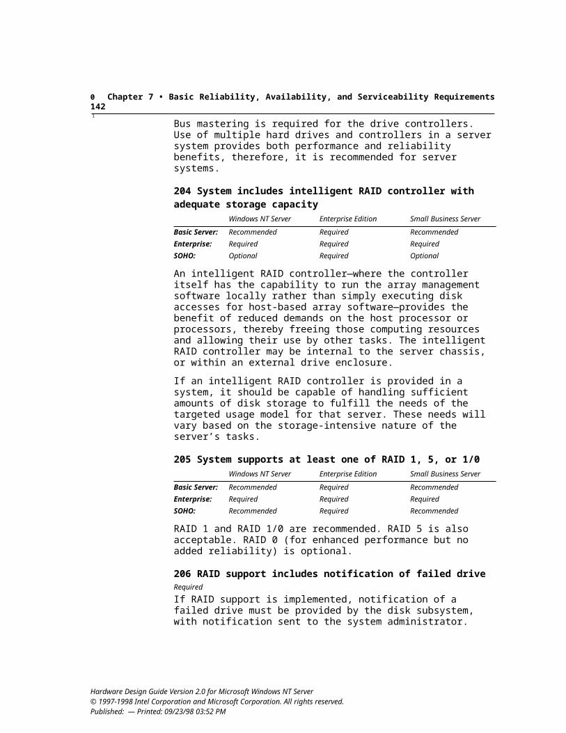
Glossary 147
power management (continued)NT Server requirements, 13–18OnNow design initiative, 5, 15–18power management timers, 13power protection, 102–103power states, 14, 15–16, 33small office/home office (SOHO) servers, 3STOP/START UNIT command, 79switch-based vs. software-based, 16–17uninterruptible power supply (UPS), 102, 106USB requirements, 35wake-up event support, 52
power management documents and specificationsAdvanced Configuration and Power Interface
Specification, xi, 5, 13Device Class Power Management Specification,
xiiNetwork Device Class Power Management Refer-
ence Specification, 52PCI Bus Power Management Interface Specifica-
tion, xiii, 33PCI Local Bus Specification, xiii, 21, 26Storage Device Class Power Management Refer-
ence Specification, 83power-on self test (POST), 17, 31, 128power states, 14, 15–16, 33power supply
protection, 102replacement indicators, 103UPS (uninterruptible power supply), 102, 106, 130
power switching in USB bus-powered hubs, 35PPP (point-to-point protocol)
asynchronous PPP, 68H.323 PPP support, 56multilink PPP, 67PPP over ATM over ADSL, 62synchronous PPP support in modems, 54UBR virtual circuits and, 60–61
preboot execution environment, 19primary graphics adapter, 44Private Loop Direct Attach (PLDA) profile, 83processors. See microprocessorspromiscuous mode support, 50protected switches, 96protocol acronyms and abbreviations, 121–123PS/2 systems. See IBM Personal System/2PTT certification, 56pulse coded modulation (PCM), 55push technology, supporting, 49push-to-close design, 86, 88PXE-based remote boot, 19
QQIC 157 cartridge specification, 91QIC (Quarter-Inch Cartridge) Drive Standards, xiv,
91, 128QoS (Quality of Service), 50, 60Quarter-Inch Cartridge (QIC) Drive Standards, xiv,
91, 128
RRA-ADSL (rate adaptive digital subscriber line), 63–
64RAID support, 103–104RAM (Random Access Memory), 128. See also
memoryrate adaptation, 61, 63–64rate adaptive digital subscriber line (RA-ADSL), 63–
64RBC (reduced block commands), 75Read Format Capacities command, 74real-mode components, 38real-time clock alarms, 14real-time processing, 128recommended hardware features, Windows NT
Server, viiiRed Book format, 85, 87reduced block commands (RBC), 75reduced instruction set computing (RISC), xi, 6, 129redundant power supplies, 102registry
defined, 128device driver configuration settings, 38modem INF entries and registry keys, 56network adapters, performance tuning, 49
reliability. See also fault conditions and fault tolerance
backup hardware, 90–92, 102NT Server requirements, 101–105in server design, 1
remote management capabilitiesnetwork adapter support, 49remote alerts and controls, 98remote boot capabilities, 19remote device management and setup, 107–108server security, 108
removing devices, 23removing software, 38replacement indicators
drive replacement indicators, 106power supplies, 103
Hardware Design Guide Version 2.0 for Microsoft Windows NT Server © 1997-1998 Intel Corporation and Microsoft Corporation. All rights reserved. Published: July 22, 1998 — Printed: 09/23/98 03:52 PM
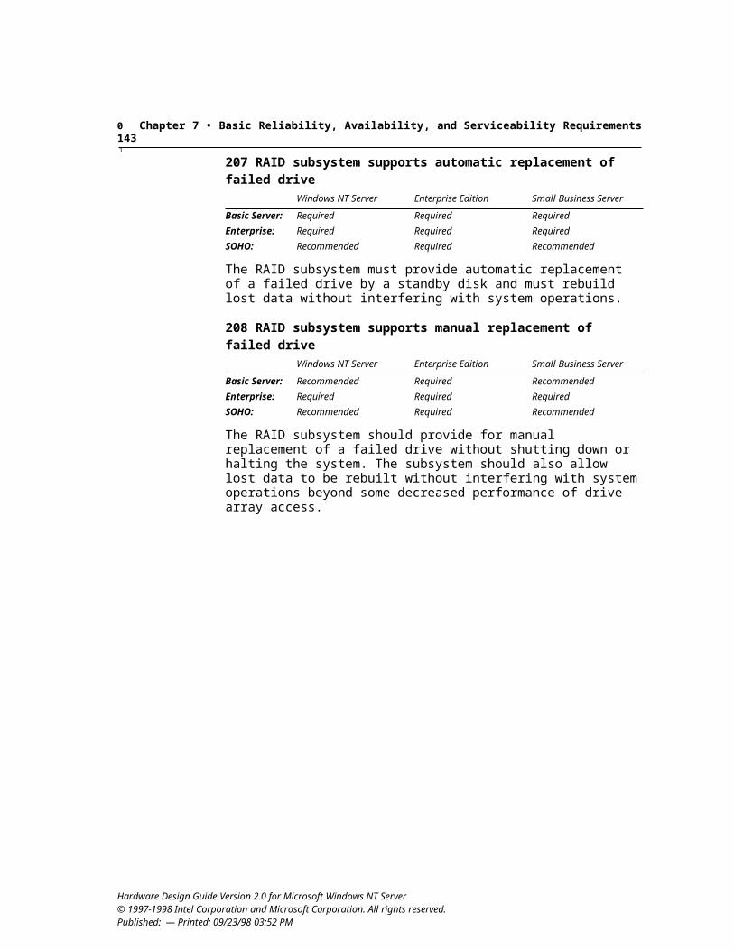
Glossary 148
required hardware features, Windows NT Server, viiirequirements checklist, 109–120RESET command, ATAPI, 82resource allocation and conflicts
3F7h and 377h address ranges, 82ACPI requirements, 14legacy serial port conflicts, 40–41network adapter resource settings, 51Plug and Play requirements, 21, 42resources, defined, 128
retrieval and information database (RAID), 103–104RFC 1717, 67RF return modems, 64RISC-based systems, xi, 6, 129. See also DEC Alpha-
based systemsrobustness, in server design, 2ROM BIOS interrupt services, 6RPC II specification, 88rt (real time), 129
SS3 or S4 states, 33S4BIOS state, 16S5 soft-off feature, 14scalability in server design, 2, 3, 129SCAM support, 79scan codes
keyboard-based power switches, 17PS/2-style ports, 39
screen display at startup, 18SCSI adapters and peripherals
auto-configuration of media changers, 93color-coding ports and connectors, 96erasable disk drives, 83–84media status notification, 75, 79NT Server requirements, 76–79optical disk changers, 92–93SCSI defined, 129Small Computer Interface (SCSI-3) Parallel Inter-
face (SPI) Specification, 77tape changers, 92–93tape drive compliance, 91
SDKs. See names of specific SDKssecurity
NT Server hardware security requirements, 97–99preboot passwords, 19remote device management, 108in server design, 2Trusted Computer System Evaluation Criteria, 97
serial numbers on hardware, 22
serial ports and devicesBIOS configuration, 41bus requirements, 40color-coding ports and connectors, 96console redirection as boot device, 20design requirements, 40–41IRQ usage, 40ISDN modems, 67–68legacy serial ports, 40–41serial modems, 53, 54, 67–68
server design. See Windows NT Server designserver requirements checklist, 109–120serviceability in server design, 2, 3service profile identifiers (SPID), 67, 69SFF (Small Form Factor) documents and
specificationsSFF 8020i (ATA Packet Interface for CD-ROM),
xii, 85, 91SFF 8038i, 81SFF 8070i, 74, 75SFF 8090 (Mt. Fuji specification), 88
SGL support, 77shared interrupts, 27–28, 31shielded connectors, 78shrouded connectors, 78, 82, 95SID (Subsystem IDs), 30–31Simple Boot Flag Specification, Version 1.0, 18single-ended signal type, 77SIR data devices, 70sleep states
ACPI compliance, 14, 18indicators, 15OnNow design initiative compliance, 15–16PCI bus power states, 33resume time, 17
Small Business Server (Microsoft), ix, 4Small Computer Interface (SCSI-3) Parallel Interface
(SPI) [X3T9.2/91-10] Specification, 77small computer system interface. See SCSI adapters
and peripheralsSmall Form Factor Standards. See SFF (Small Form
Factor) documents and specificationssmall office/home office servers. See SOHO serverssmart cards, 98–99, 129SMBIOS support, 108SMP (symmetric multiprocessing), 11snap-on connectors, 97snooping cache coherency mechanisms, 28soft-off feature, 14software-based power control, 16–17software developers kits. See names of specific SDKssoftware devices, 129
Hardware Design Guide Version 2.0 for Microsoft Windows NT Server © 1997-1998 Intel Corporation and Microsoft Corporation. All rights reserved. Published: July 22, 1998 — Printed: 09/23/98 03:52 PM
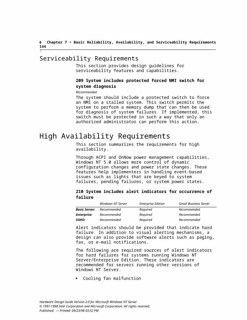
Glossary 149
SOHO serversACPI support, 14–15analog phone connection, 69–70modem issues, 53, 54NT Server requirements, 3OnNow support, 15–18Simple Boot Flag Specification, 18SOHO server class, ix
Sony ReadTOC method, 85speaker ports and connectors, 96speed. See also performance
DVD-ROM devices, 86dynamic link speed configuration, 61high-speed communications, 40ISDN speed requirements, 68processor speed, 11tape drive requirements, 91
SPID (service profile ID), 67, 69spin down, 129SPI specification, 77splash screens, 18standby power, 17startup display, 18static resources, 21, 129S/T interface for ISDN devices, 69–70STOP/START UNIT command, 79storage components
ATA controllers and peripherals, 80–83IEEE 1394 storage devices, 76locking devices, 79multiple hard drives, 103NT Server requirements, 73–76RAID controllers, 103–104SCSI storage devices, 76–79USB storage devices, 75
Storage Device Class Power Management Reference Specification, 83
streams, 129subpicture decoder, 89Subsystem and Subsystem Vendor IDs, 30–31SVGA (Super VGA), 129SVID (Subsystem Vendor IDs), 30–31switches. See power buttonssymmetric multiprocessor support, 11synchronous access for modems, 56synchronous PPP, 54, 68system-board devices, 13, 30–31system boards, 129system components, high-performance, 9system devices, vii, 22, 129system ID structure, 18–19system memory. See memory
system startupBIOS support, 18–21CD-ROM boot support, 19Fast POST recommendations, 17hot-key override, 18minimizing boot time, 17network adapter support, 19–20OnNow design initiative compliance, 17–18preboot execution environment, 19security support, 19serial port redirection from console, 20startup display, 18system ID structure, 18–19update support for BIOS, 20USB keyboard support, 20
TT1.413 Issue 2 specification, 63T1 lines, 55T13-1226DT, 74tape changers, 92–93tape drives
media status notification, 75NT Server requirements, 90–92tape changers, 92–93
TAPI (Telephony Application Program Interface), 58, 129
task-offload mechanisms, NDIS, 47TCO (total cost of ownership), 2TCP/IP, 47, 129TCP message segmentation, 47TDD (Telephone Device for the Deaf), 57Telephone API (TAPI), 58, 129Telephone Device for the Deaf, 57telephony, 129Telephony Application Program Interface, 58, 129temperature alert, 106termination, 70, 77, 78TERMPWR (terminator power), 78testing
compliance dates, xidevice and driver compliance testing, 38DVD performance, 89HCL, x, xiiioverview, xsystem configurations, 10
Text Telephone, 57TFTP (Trivial File Transfer Protocol), 19
Hardware Design Guide Version 2.0 for Microsoft Windows NT Server © 1997-1998 Intel Corporation and Microsoft Corporation. All rights reserved. Published: July 22, 1998 — Printed: 09/23/98 03:52 PM
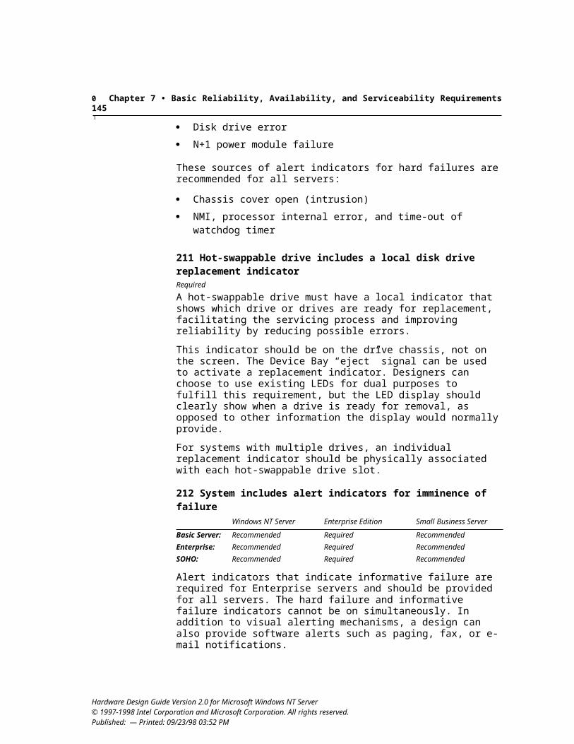
Glossary 150
thermal models, 14TIA communications documents and specifications
TIA-578-A, 55TIA-592, 55TIA-602, 54, 66, 67TIA-695, 58TIA IS-101-1994, 58
time continuity in DVD, 88–89timeout model in MMC-2, 87Token Ring network adapters, 52total cost of ownership (TCO), 2traffic shaping, 60transceiver types, sensing, 48transfer rates for DVD-ROM devices, 86troubleshooting. See also fault conditions and fault
toleranceATM OAM support, 61emergency repair support, 43serial port, as boot device, 20
Trusted Computer System Evaluation Criteria, 97tuning parameters, network adapters, 49two-way modems, 64
UUADSL implementations, 63UARTs (Universal Asynchronous
Receiver/Transmitter), 40, 129UBR (unspecified bit rate), 60UDF CD format, 85UDMA-33 devices, 81UHCI Specification, xiv, 35U-interface, 69Ultra-DMA (Ultra-ATA), 29, 81–82unattended installation. See also remote management
capabilitiesdevice drivers, 38IrDA drivers, 71ISDN modem drivers, 68
undervoltage protection, 102Unimodem
defined, 129diagnostics command, 57ISDN adapter support, 66serial modem driver, 53
Unimodem Diagnostics Command Reference Specification, xiv
Unimodem ID Command Reference Specification, xivuninstalling software, 38
uninterruptible power supplies (UPSs), 102, 106, 130Universal Asynchronous Receiver/Transmitter
(UART), 40, 129universal disk format (UDF), 85Universal HCI (UHCI) Specification, xiv, 35Universal Host Controller Interface (UHCI), xiv, 35universal modem driver. See UnimodemUniversal Serial Bus documents and specifications.
See also USB (Universal Serial Bus)Universal Serial Bus Device Class Definition De-
vice Bay Controllers, 24Universal Serial Bus Device Class Definition for
Mass Storage Devices, 75Universal Serial Bus (USB) device class specifica-
tions, xivUniversal Serial Bus PC Legacy Compatibility
Specification, xiv, 20Universal Serial Bus Specification, xiv, 21, 34, 39USB Common Class Specification, 35USB Human Interface Device Class Specification,
39USB Serial Bus PC Legacy Compatibility Specifi-
cation, 40unspecified bit rates (UBR), 60upgrade support, 20UPSs (uninterruptible power supplies), 102, 106, 130URLs. See Web sites and FTP addressesUSB (Universal Serial Bus). See also USB (Universal
Serial Bus) documents and specificationsbus and device class specifications, xivcolor-coding ports and connectors, 96defined, 130Device Bay requirements, 24host controller, 14–15, 35icons, 34keyboards and mouse ports, 20, 39–40mass storage devices, 75miniport drivers for network adapters, 46network adapters, 51NT Server design requirements, 34–35parallel port implementations, 41USB class, 130Windows NT Server support, 4
USB (Universal Serial Bus) documents and specifications. See also USB (Universal Serial Bus)
Universal Serial Bus Device Class Definition De-vice Bay Controllers, 24
Universal Serial Bus Device Class Definition for Mass Storage Devices, 75
Hardware Design Guide Version 2.0 for Microsoft Windows NT Server © 1997-1998 Intel Corporation and Microsoft Corporation. All rights reserved. Published: July 22, 1998 — Printed: 09/23/98 03:52 PM
Glossary 151
USB documents and specifications (continued)Universal Serial Bus (USB) device class specifica-
tions, xivUniversal Serial Bus PC Legacy Compatibility
Specification, xiv, 20Universal Serial Bus Specification, xiv, 21, 34, 35,
39USB Common Class Specification, 35USB Human Interface Device Class Specification,
39USB Serial Bus PC Legacy Compatibility Specifi-
cation, 40USB keyboard devices. See keyboardsuser mode and user-mode drivers, 130user-tunable parameters, network adapters, 49
VV.8 and V.8bis modem support, 54, 56V.17 modem support, 55V.18 modem support, 57V.25 modem support, 56V.25ter modem support, 57V.34 modem support, 54V.42 and V.42bis modem support, 55V.61 ASVD modem support, 56V.70 DSVD modem support, 56V.80 modem support, 54, 56V.90 modem support, 54V.250 modem support, 54, 55, 57V.251 modem support, 54, 56V.253 modem support, 58validation of media types, 88–89VAR (value added resellers), 130VBR (variable bit rate) connections, 60VCI (Virtual Channel Identifier) ranges, 59VDM (virtual device manager), 6VESA (Video Electronics Standards Association), 44,
130VGA
color-coding ports and connectors, 96VGA-compatible devices, 28VGA-mode support, 44
video miniport drivers, 7video playback, DVD-ROM, 88, 89, 90video ports and connectors, 96video telephony, 56virtual channel identifiers (VCI), 59virtual device drivers, 6Virtual Device Manager (VDM), 6virtual hardware, 6
virtual path identifiers (VPI), 59virtual-x86 processor mode, 6voice/data/video software for modems, 56voice modems, 58. See also modemsVPI (Virtual Path Identifier) ranges, 59
WWake-On-LAN capability, 52waking systems, 14, 15–16, 17, 52WAN (wide area network), 47, 130watchdog timer time-out alert, 105WBEM (Web-Based Enterprise Management)
defined, 130manageability baseline requirements, 107management component instrumentation require-
ments, 108Web site, xivWindows NT Server support, 4
WDM (Windows Driver Model)defined, 130minidriver support, 38miniport driver requirements, 47OnNow design initiative and, 5USB connections, 39
Web-Based Enterprise Management. See WBEM (Web-Based Enterprise Management)
Web sites and FTP addressesAdvanced Configuration and Power Interface
Specification, xi, 5Advanced RISC Computing Multiprocessor Stan-
dard Specification, xiATM User-Network Interface Specification, xiiCommon Information Model (CIM), xiCompaq, Intel, Phoenix BIOS Boot Specification,
xiiDesktop Management Interface Specifications, xiiDesktop Management Task Force (DMTF), xiDevice Class Power Management Specification,
xiiDMI Compliance Guidelines, xiidriver signing program, 10DVD-ROM devices and Windows NT support, 86El Torito—Bootable CD-ROM Format Specifica-
tion, xiiFibre Channel Association, xii, 83HCL information, x, xiiiHCT kits, xhot-plugging support article, 79I20 (Intelligent I/O) Architecture Specification, xii
Hardware Design Guide Version 2.0 for Microsoft Windows NT Server © 1997-1998 Intel Corporation and Microsoft Corporation. All rights reserved. Published: July 22, 1998 — Printed: 09/23/98 03:52 PM
Glossary 152
Web sites and FTP addresses (continued)icon examples, 95IETF Integrated Services user priority objects, 50Information Technology Enhanced BIOS Services
for Disk Drives, xiii, 74Instantly Available PC System Power Delivery Re-
quirements and Recommendations, 17Intel developer information, x, xiInteroperability Specification for ICCs and Per-
sonal Computer Systems, xiii, 98An Interoperable End-to-End Broadband Service
Architecture over ADSL Systems, xii, 62MCNS documents, xiiiMedia Status Notification, xiiiMicrosoft hardware developer information, xiMicrosoft Platform SDK, xiiiMMC-2 Multi-Media Command Set-2 standard,
xiiiModem Developers Kit, xiii, 53MSDN Professional Membership, xi, xiiiMultiProcessor Specification, xiiiNational ISDN Basic Rate Interface Terminal
Equipment Generic Guidelines, xiNDIS 5.0 information, xiii, 45network adapter wake-up event support notes, 52Network PC System Design Guidelines, xiiiNTMS Programmers Guide, xiii, 93NT Server design, v, xOnNow design initiative, 5Open Host Controller Interface (OpenHCI) Speci-
fication, xiiiPCI Bus Power Management Interface Specifica-
tion, xiiipci.exe Configuration Space debugging program,
31PCI Local Bus Specification, xiiiPlug and Play specifications, xivQoS articles, 50Quarter-Inch Cartridge (QIC) Drive Standards, xivscan codes for keyboard-based power switches, 17server hardware design, xSubsystem ID ECN information, 30T1.413 Issue 2 specification, 63Unimodem Diagnostics Command Reference Spec-
ification, xivUnimodem ID Command Reference Specification,
xivUniversal HCI (UHCI) Specification, xivUniversal Serial Bus (USB) device class specifica-
tions, xivUniversal Serial Bus PC Legacy Compatibility
Specification, xiv
Universal Serial Bus Specification, xivWeb-Based Enterprise Management (WBEM) in-
formation, xivWHQL information, x, xiWin32 Extensions schema, xivWindows management instrumentation, xivWindows NT 5.0 DDK, xiiiWindows NT Server features and capabilities, 5
WfM (Wired for Management), 97, 106WHIIG (Windows Hardware Instrumentation
Implementation Guidelines), 97, 106–107, 108White Book format, 85, 87WHQL (Windows Hardware Quality Labs), x–xi, 130Win32 API, 130Win32 Extensions schema, xivWindows Dial-Up Networking, 60–61Windows Driver Model. See WDM (Windows Driver
Model)Windows Hardware Instrumentation Implementation
Guidelines (WHIIG), 97, 106–107, 108Windows Hardware Quality Laboratory (WHQL), x–
xi, 130Windows Management Instrumentation (WMI)
defined, 130manageability baseline requirements, 107Web site, xivWindows NT Server support, 4
Windows NT. See also Windows NT Server designDDK, 130defined, vii, 130Hardware Compatibility List (HCL), x, xiii, 9, 10Hardware Compatibility Tests (HCT), x, 10, 126Help files, 39NTFS (Windows NT file system), 127NTMS (Windows NT Media Services), xiii, 4, 93Windows NT DDK, xiii, 38
Windows NT DDK, xiii, 38Windows NT Server design
classes of servers, ix, 3–4custom-designed systems, viiidesign issues, 1–2goals, 2hardware initiatives, 4high-performance components, 9Intel and Microsoft information, xmicroprocessor platform requirements, 6–7minimum system requirements, vNT Server defined, viiNT Server editions, 4
Hardware Design Guide Version 2.0 for Microsoft Windows NT Server © 1997-1998 Intel Corporation and Microsoft Corporation. All rights reserved. Published: July 22, 1998 — Printed: 09/23/98 03:52 PM
Glossary 153
Windows NT Server design (continued)NT Server features and capabilities, 4, 5OnNow design and ACPI support, 5required, recommended, and optional hardware
features, viiirequirements checklist, 109–120
Windows Quality of Service, 50, 60WinSock (Windows Sockets), 58Wired for Management Baseline Specification, 97,
106WMI. See Windows Management Instrumentation
(WMI)word buffer alignment, 48write-back cache, 11
XX3T11 Private Loop Direct Attach (PLDA) profile, 83X.25 miniport driver requirements, 46
Yyear 2000+, date support, 10Yellow Book format, 85, 87YUV offscreen surface support, 90
ZZero Administration for Windows initiative, 106, 130
Hardware Design Guide Version 2.0 for Microsoft Windows NT Server © 1997-1998 Intel Corporation and Microsoft Corporation. All rights reserved. Published: July 22, 1998 — Printed: 09/23/98 03:52 PM
Glossary 154
Hardware Design Guide Version 2.0 for Microsoft Windows NT Server © 1997-1998 Intel Corporation and Microsoft Corporation. All rights reserved. Published: July 22, 1998 — Printed: 09/23/98 03:52 PM