HARDWARE DESIGN FOR CRYPTOGRAPHIC PROTOCOLS: AN ...€¦ · Dr. Sudarshan Srinivasan Chair Dr....
155
HARDWARE DESIGN FOR CRYPTOGRAPHIC PROTOCOLS: AN ALGORITHMIC STATE MACHINE DESIGN APPROACH A Thesis Submitted to the Graduate Faculty of the North Dakota State University of Agriculture and Applied Science By Gerardo Alejandro Zamora Garcia In Partial Fulfillment of the Requirements for the Degree of MASTER OF SCIENCE Major Department: Electrical and Computer Engineering April 2016 Fargo, North Dakota
Transcript of HARDWARE DESIGN FOR CRYPTOGRAPHIC PROTOCOLS: AN ...€¦ · Dr. Sudarshan Srinivasan Chair Dr....

HARDWARE DESIGN FOR CRYPTOGRAPHIC PROTOCOLS: AN
ALGORITHMIC STATE MACHINE DESIGN APPROACH
A Thesis
Submitted to the Graduate Faculty
of the
North Dakota State University
of Agriculture and Applied Science
By
Gerardo Alejandro Zamora Garcia
In Partial Fulfillment of the Requirements
for the Degree of
MASTER OF SCIENCE
Major Department:
Electrical and Computer Engineering
April 2016
Fargo, North Dakota

North Dakota State University
Graduate School
Title
HARDWARE DESIGN FOR CRYPTOGRAPHIC PROTOCOLS: AN
ALGORITHMIC STATE MACHINE DESIGN APPROACH
By
Gerardo Alejandro Zamora Garcia
The Supervisory Committee certifies that this disquisition complies with North Dakota State
University’s regulations and meets the accepted standards for the degree of
MASTER OF SCIENCE
SUPERVISORY COMMITTEE:
Dr. Sudarshan Srinivasan
Chair
Dr. Rajendra Katti
Dr. Scott Smith
Approved:
13 April 2016 Dr. Scott Smith
Date Department Chair

iii
ABSTRACT
This thesis presents Algorithmic State Machine (ASM) designs that follow the One Cycle
Demand Driven Convention (OCDDC) of three cryptographic protocols: Secure Distributed
Multiplication (SDM), Pi Secure Distributed Multiplication (PiSDM, or secure distributed
multiplication of a sequence), and Secure Comparison (SC), all of which achieve maximum
throughput of 1/32, 1/(32(l - 1)), and 1/(32(l - 1)), respectively, for l-bit numbers. In addition,
these protocols where implemented in VHDL and tested using ModelSim-Altera, verifying their
correct functionality. Noting that the difference between a scheme and a protocol is that
protocols involve message exchanging between two or more parties, to the author's knowledge,
these hardware designs are the first ever implementations of any kind of cryptographic protocol,
and because of that reason, a general method is proposed to implement protocols in hardware.
The SC protocol implementation is also shown to have a 300,000+ speed up over its Python
implementation counterpart.

iv
ACKNOWLEDGEMENTS
I would like to thank Dr. Raj Katti for being the professor that motivated my interest in
the two very different areas of cryptography and digital hardware design. I would also like to
thank my advisor, Dr. Srinivasan, and my advanced digital design professor and NDSU ECE
chair, Dr. Smith, for their willingness to help me with my thesis. Finally, I would like to thank
my family and friends for their enormous love and support that have inspired me throughout the
years.

v
DEDICATION
To Rogelia, as I know you are watching me from Heaven, I dedicate the result of my biggest
endeavor yet to you.

vi
TABLE OF CONTENTS
ABSTRACT ................................................................................................................................... iii
ACKNOWLEDGEMENTS ........................................................................................................... iv
DEDICATION ................................................................................................................................ v
LIST OF TABLES ....................................................................................................................... viii
LIST OF FIGURES ....................................................................................................................... ix
LIST OF APPENDIX FIGURES................................................................................................... xi
1. INTRODUCTION ..................................................................................................................... 1
1.1. Definitions ........................................................................................................................... 3
1.2. Background and Motivation ................................................................................................ 6
1.3. Related Work in Hardware Implementations .................................................................... 13
1.4. Contributions ..................................................................................................................... 14
1.5. Thesis Outline ................................................................................................................... 14
2. DESIGNS AND IMPLEMENTATIONS ................................................................................ 16
2.1. Secure Distributed Multiplication (SDM) ......................................................................... 17
2.1.1. Original Protocol ........................................................................................................ 18
2.1.2. ASM Design ............................................................................................................... 19
2.1.3. Protocol Complexity and ASM Throughput .............................................................. 32
2.1.4. Protocol Modification for Hardware .......................................................................... 33
2.1.5. VHDL Implementation Details .................................................................................. 33
2.1.6. Sample Run................................................................................................................. 35
2.2. Secure Distributed Multiplication of a Sequence (PiSDM) .............................................. 37
2.2.1. Original Protocol ........................................................................................................ 38
2.2.2. ASM Design ............................................................................................................... 39

vii
2.2.3. Protocol Complexity and ASM Throughput .............................................................. 47
2.2.4. VHDL Implementation Details .................................................................................. 48
2.2.5. Sample Run................................................................................................................. 50
2.3. Secure Comparison (SC) ................................................................................................... 51
2.3.1. Original Protocol ........................................................................................................ 51
2.3.2. ASM Design ............................................................................................................... 53
2.3.3. Protocol Complexity and ASM Throughput .............................................................. 59
2.3.4. Optimizing l and Selecting q for the Biggest Integer Range ...................................... 60
2.3.5. VHDL Implementation Details .................................................................................. 62
2.3.6. Sample Run................................................................................................................. 64
3. PROPOSED GENERAL METHOD TO DESIGN AND IMPLEMENT
CRYPTOGRAPHIC HARDWARE ............................................................................................. 66
4. RESULTS AND CONCLUSIONS.......................................................................................... 68
4.1. Results ............................................................................................................................... 68
4.2. Conclusions ....................................................................................................................... 69
4.3. Future Work ...................................................................................................................... 70
5. WORKS CITED ...................................................................................................................... 72
APPENDIX A. COMPONENT DESIGN ................................................................................... 74
APPENDIX B. VHDL CODE ..................................................................................................... 78
APPENDIX C. OTHER CODE ................................................................................................. 137

viii
LIST OF TABLES
Table Page
1: SDM Analysis and Synthesis Report from Quartus II ............................................................ 35
2: PiSDM Analysis and Synthesis Report from Quartus II ........................................................ 49
3: SC Analysis and Synthesis Report from Quartus II................................................................ 63
4: SC Python Timing Results ...................................................................................................... 68

ix
LIST OF FIGURES
Figure Page
1: ASM General Model. Taken from [29] ................................................................................... 8
2: GCD ASM Design. Taken from [22] ..................................................................................... 11
3: SDM Interfaces ....................................................................................................................... 20
4: SDM TI’s ASM ....................................................................................................................... 21
5: SDM TI’s Data Path ................................................................................................................ 22
6: SDM A’s ASM ........................................................................................................................ 23
7: SDM A’s Data Path ................................................................................................................. 27
8: SDM B’s ASM ........................................................................................................................ 30
9: SDM B’s Data Path ................................................................................................................. 31
10: SDM TPC Diagrams ............................................................................................................... 33
11: SDM Sample Run ................................................................................................................... 37
12: PiSDM Interfaces .................................................................................................................... 40
13: PiSDM A’s ASM..................................................................................................................... 43
14: PiSDM A’s Data Path.............................................................................................................. 44
15: PiSDM B’s ASM..................................................................................................................... 46
16: PiSDM B’s Data Path.............................................................................................................. 47
17: PiSDM TPC Diagrams ............................................................................................................ 48
18: PiSDM Sample Run ................................................................................................................ 50
19: SC Interfaces ........................................................................................................................... 53
20: SC A’s ASM ............................................................................................................................ 56
21: SC B’s ASM ............................................................................................................................ 57
22: SC A’s Data Path ..................................................................................................................... 58
23: SC B’s Data Path ..................................................................................................................... 59

x
24: SC TPC Diagrams ................................................................................................................... 60
25: SC Sample Run ....................................................................................................................... 65

xi
LIST OF APPENDIX FIGURES
Figure Page
A - 1: RegS Component ............................................................................................................... 74
A - 2: Modular Addition Component........................................................................................... 74
A - 3: Modular Subtraction Component ...................................................................................... 75
A - 4: Modular Multiplication Component .................................................................................. 75
A - 5: Shift Register with Parallel Load Component ................................................................... 75
A - 6: AddShares Component ...................................................................................................... 76
A - 7: AddShares1 Component .................................................................................................... 76
A - 8: SubShares Component ....................................................................................................... 77
A - 9: SigmaShares Component ................................................................................................... 77

1
1. INTRODUCTION
The need for cryptography in different industries like banking, finances, and commerce,
intellectual property protection, and telecommunications, to name a few, is clear nowadays. In
some not so distant decades, however, that was not so clear. Even though it might have seen
understandable back then because digital technology had not boomed to the point it has in
present years, we now know that we live in a digital age even though, in the past, it was believed
that personal computers (PCs) and home computers were not expected to beat an average of 1
per household, which we understand it is far from the truth in the present. In fact, according to
TekCarta, an online research service described by Reuters as "An innovative, New Business
Model for Technology Industry Research" in [14], shows that by 2012, the average of PCs per
household in the United States had already reach 3 [15]. This statistic does not even include
mobile devices, so we can tell just how much depend on computers, and their security, every
single day. This is where cryptography comes into play.
Cryptography, as a whole, has more goals than just security. Some of those are data
integrity, authentication, and privacy, among others. For example, in the case of privacy in
protocols, cryptography's goal is to keep every party's secret information hidden from any other
party. So to be more specific, when a protocol is needed to compute a function or mathematical
construct using the secret values that each party holds, this protocol is considered a distributed
computation, and it is by using the rules of cryptography that we can achieve privacy for each
party, so that their sensitive information is not revealed to any unwanted party.
Moreover, secure distributed computation, in the world of cryptography, is an area which
has been highly researched in the past few decades. Starting from Yao's protocol [Yao ‘82] to
even elliptic curves, researchers have focused on finding efficient implementations of
2
cryptographic primitives, constructs and schemes in order to further our capabilities with secure
computations to breach the gap between theoretical and practical cryptography. One of the
endeavors to accomplish such a goal, even though it adds difficulty to the implementation, is the
usage of hardware over software due to their differences in speed.
As the field of cryptography progressed, researchers and engineers moved to
implementing protocols in software because of the different results protocols were able to
accomplish. So in later years now, with all the advances in transistor sizing, FPGA technology,
and secure computation theory, it is natural to continue the implementation of cryptographic
construct in the hardware realm. In fact, several primitives and schemes have been implemented,
like SHAs (hashing algorithms), RSA (encryption scheme and cryptosystem), and others;
however, no protocol has ever been implemented in hardware.
On the hardware side, our focus lies on the state machine design, more specifically,
finite-state machine design. There are several of these, for example, Mealy machines which
were introduces in 1955 by George Mealy [16], Moore machines introduced by Edward Moore
in 1956 [17], and Algorithmic State Machines (ASMs) seen as early as the 70s [18] and 80s [19,
20, 21], with ASMs being the more advanced of the three mentioned. In the case of Mealy and
Moore machines, state diagrams are used to determine state transitioning, state outputs, and so
on, deriving the state and output logic from the diagram itself, requiring no extra logic or
components. On the other hand, an ASM can be used to achieve more complex results by using
a data path for processing more complicated data inputs to determine the output, and a control
unit to manage the data path and state transitioning.

3
1.1. Definitions
The following definitions are used throughout the whole thesis and are intended for those
who do not have a basis in cryptography, digital systems, and algorithmic state machine design.
This section may be skipped if the reader is comfortable with the aforementioned areas.
• Cryptographic Construct: simply, a general term for any construct which performs
some task with the usage of cryptography to achieve one or more of the goals of cryptography.
For example, encryption achieves privacy and data protection, message authentication codes
(MACs) are used for data integrity checks (indicating whether the data received was altered or
not), digital signatures helps achieve non-repudiation (i.e. someone who signed a message and
send it, cannot later deny it came from him/her).
• Cryptographic Primitive: a cryptographic primitive is considered a basic building
block for cryptographic schemes and protocols. For example: encryption/decryption schemes,
message authentication codes, cryptographic hash functions, secret sharing, additive shares, and
others.
• Cryptographic Scheme: a set of algorithms and/or primitives ran by two parties
that achieve a certain goal without the exchange of multiple messages. For example, in an
encryption scheme, there is an encryption algorithm or equation to compute a ciphertext, and a
different algorithm used to perform decryption. In this case, one party does the encryption and
sends the ciphertext to another party who then performs the decryption algorithm. So there is
only one message, the ciphertext, being sent.
• Cryptographic Protocol: similar to a crypto scheme, a protocol is a set of
algorithms, with the prevalent difference being that multiple messages are exchanged between
two or more parties. In addition, a cryptographic protocol aims to achieve or obtain a more

4
complicated result. For example, the protocols implemented in this thesis achieve secure
distributed multiplication and secure integer comparison, two task that require additive shares to
achieve privacy. This means that a scheme could not easily accomplish this because these
protocols need two parties to preserve the secret numbers as secret.
• Protocol Transcript: this refers to the messages being exchanged in a protocol.
This includes the messages' actual values, but mainly, the randomness distribution of each
message. For example, some message might be a bit equal to 1 which was chosen uniformly at
random over {0, 1}; whereas other messages may have uniform distributions over a different set
like Zq or Zq*.
• Universal Composability (UC) Model: a model describing requirements for a
protocol to be secure when executed in composition (in series or in parallel) with any other
protocol. This obviously implies that a protocol which is secure under the UC model is also
secure when executed in isolation.
• Adversary: a party in a protocol which is attempting to learn another party's
secret, or compromise the protocol's goal, from the protocol's transcript.
• Semi-honest Adversary: also called "honest but curious." An adversary that does
not want to get caught cheating so it follows the protocol strictly, but tries to learn secret
information from the protocol's transcript.
• Very High-Speed Integrated Circuit (VHSIC): a U.S. Department of Defense
program in the 1980s dedicated to microelectronics research and development. One of such
developments is the hardware description language known as VHDL.
• VHSIC Hardware Description Language (VHDL): a hardware description
language.

5
• Entity (in VHDL): an entity, in VHDL, is used to represent the interface of a
circuit, indicating its inputs and outputs.
• Architecture (in VHDL): in VHDL, the architecture of an entity refers to the
internal works, or functionality, of the entity. It describes the gates, components, or operations
performed by a digital circuit with the interface provided by the entity.
• Algorithmic State Machine (ASM) design: a digital hardware design process that
is described by two parts: the ASM (or control unit) and the data path to compute the outputs
from the inputs.
• Data Path (of a state machine): a digital circuit that receives the input data to
compute the output data. The data flow in the data path is controlled by the ASM.
• ASM: a state machine used to assert the signals that control the data flow in the
data path at the appropriate time to achieve the desired behavior.
• One Cycle Demand Driven Convention (OCDDC): handshaking mechanism used
in ASM design for module’s I/O. OCDDC requires a request line and a data line. This adds a
new output Xrqst and a new input Xdat for every set of inputs X needed at the same clock cycle.
Xrqst is used by the ASM to request the set of inputs it requires, and Xdat is used to indicate the
validity of the input or inputs to the ASM. It also creates a new input Yrqst and a new output
Ydat for every set of outputs Y. In the case of Y, Yrqst is to tell the ASM that the output Y is
ready to be received, and Ydat is used by the ASM to indicate whether Y is valid or not. Simply
put, whether it is an input or an output, the request line is asserted when data is ready to be read
in, and the data line is assert when data is valid.
• Throughput Capability (TPC): the number of clock cycles where an input is
loaded over the total number of clock cycles needed to calculate the output, and it only considers

6
the steady-state of an ASM. When calculating TPC of an ASM, it is assumed that data is ready
to be received as soon as it is ready and that it is always ready when requested. This assumption,
though, can be ignored when the designer explicitly knows that it won’t hold (See SDM B’s
ASM for details and example in Sections 2.1.2 and 2.1.3). Note: in the case that the ASM has no
data input, then the TPC refers to the number of clock cycles needed to calculate the output.
• TPC Diagram: a diagram that shows the steady-state input data loading and state
transitioning of an ASM.
• Maximum TPC: the maximum achievable TPC, which can be obtained by
inspection of the original algorithm.
1.2. Background and Motivation
Secure distributed multiplication (SDM) was first proposed by Beaver in 1992 in the
context of multi-party protocols [13], where n parties compute a function F of all parties' secret
inputs. In order to come up with the result, F is expressed as a circuit CF, so that party i, with its
secret xi, can compute secret addition and multiplications on secretly shared values. This is done
until all n parties have provided their inputs. After Beaver, there have been more developments
in SDM, for example, Gennaro, Rabin, and Rabin [23] showed a highly simplified protocol for
secure multiplication of shared secrets, with O(n2k log n+nk
2) complexity, that was shown to
improve the efficiency of other secure multi-party computation protocols when using their SDM
instead of previously developed multiplication protocols. Another example is the work of
Ronald Cramer, Ivan Damgård, and Robbert de Haan [24], where they based their work on
Shamir's secret sharing scheme in [26]. Later on, in 2007 and 2009, Peter Lory reduced the
complexity of the previously mentioned Gennaro, Rabin, and Rabin protocol to O(n2k+nk
2) and
O(n2k), respectively [25, 27]. Moreover, SDM has several potential uses. For example, David,

7
Dowsley, Katti, and Nascimento have shown one of them in [1]. They have used SDM to
compute secure distributed π-products (PiSDM), or secure distributed product of a sequence, in
order to ultimately perform secure integer comparison in the Universal Composability (UC)
security threat model under semi-honest adversary’s attacks. The UC model gives the strongest
security since it assumes that the protocol can be combined or composed with any other protocol
in both serial and parallel manners. Secure integer comparison, can then be used to accomplish
secure silent auctions as in [28], which was a real-life application of cryptography supported by
the Danish Strategic Research Council and the European Commission. Also, it could potentially
be used in a secure protocol that solves the problem of whether an integer lies within a certain
range. Other applications include privacy preservation in machine learning and location-based
services. Besides having all of the aforementioned applications as motivation for implementing
these protocols, it should also be taken into account that another strong motivation for
implementing SDM is the following: since it can be shown that addition and multiplication span
Zq, a fast implementation of multiplication, the more complicated of the two, will greatly
improve performance of other protocols that have already been developed or proposed by
industry and academia.
Looking a bit more into ASM design, as Smith and Di have explained in section 4.2 of
[22], ASMs are used to implement complex sequential circuits, which would be too large for
Mealy or Moore machines due to their exponential increase in size relative to the state transition
bits. In the case of algorithmic state machine design, more elaborated state transition conditions
can be used because of its combined ASM and Data Path approach, allowing for conditional
transitions like input data comparison without exponentially increasing the number of states.
The general ASM model is also described in [29], so let us study the diagram in Figure 1:

8
Figure 1: ASM General Model. Taken from [29]
The ASM is the controller of the circuit, which gives "Commands" to the data processor
or data path. For the ASM to generate these commands, it bases its decisions on external inputs
and feedback data from the data processor, and this data processor computes the output data
based on the input data and the commands it receives from the controller.
Furthermore, for the sake of understanding ASM design and the way OCDDC is used,
consider the ASM design example given in section 4.2 of [22] as well. The design presented
calculated the Greatest Common Divisor (GCD) of two 8-bit numbers, A and B. Figure 2 shows
the complete design, which includes the Interface, ASM, and Data Path.
Starting with Figure 2a, it can be observed that the interface is simply a top-level view of
the design which simply specifies I/Os, the component's name, and the shape that should be used
to represent this circuit when it is to be used by another component. Also, from the interface, it
can be deduced that this design follows the OCDDC because of the rqst and dat suffixes used on
X and Y. This is also a good example to show that, as explained in Definitions section before,
only one rqst and one dat are required for each set of inputs that are needed by the data path at a
given state of the ASM. So applying that concept to this GCD example, it is clear that both
inputs A and B are needed before the circuit can begin computing the result, so Xrqst and Xdat
are used for both input vectors. On the case of, Y, the circuit's only output, the rqst and dat lines
9
used are simply Yrqst and Ydat. Although the interface implies the use of the OCDDC, we can
rest assured that it is actually being implemented when we examine the ASM.
To understand the ASM in Figure 2b., a basic understanding of Mealy and Moore
machines is expected but not necessary, although, this basic knowledge will make the reader
understand the ASM chart basics seamlessly. First, the rhombus or diamond, which represents a
conditional (much like the diamond used in the flowchart of a program or algorithm), showing
that the first step in the ASM is to ensure that a reset occurs (an active-high reset in this case) to
be able to determine the initial state and behavior of the finite state machine. Simply put,
resetting the ASM forces it to start at the initial state, S0 in this case. This leads us to the next
shape used: the rectangle or box, which represents a states. The state name is normally written
on top of the rectangle's top-right corner, and the state assignment is written on the top-left
corner as shown. For example, the initial state was named S0 and has been assigned the value 0.
The ASM is the controller of the circuit, which gives "Commands" to the data processor
or data path. For the ASM to generate these commands, it bases its decisions on external inputs
and feedback data from the data processor, and this data processor computes the output data
based on the input data and the commands it receives from the controller.
Furthermore, for the sake of understanding ASM design and the way OCDDC is used,
consider the ASM design example given in section 4.2 of [22] as well. The design presented
calculated the Greatest Common Divisor (GCD) of two 8-bit numbers, A and B. Figure 2 shows
the complete design, which includes the Interface, ASM, and Data Path.
Starting with Figure 2a, it can be observed that the interface is simply a top-level view of
the design which simply specifies I/Os, the component's name, and the shape that should be used
to represent this circuit when it is to be used by another component. Also, from the interface, it
10
can be deduced that this design follows the OCDDC because of the rqst and dat suffixes used on
X and Y. This is also a good example to show that, as explained in Definitions section before,
only one rqst and one dat are required for each set of inputs that are needed by the data path at a
given state of the ASM. So applying that concept to this GCD example, it is clear that both
inputs A and B are needed before the circuit can begin computing the result, so Xrqst and Xdat
are used for both input vectors. On the case of, Y, the circuit's only output, the rqst and dat lines
used are simply Yrqst and Ydat. Although the interface implies the use of the OCDDC, we can
rest assured that it is actually being implemented when we examine the ASM.
To understand the ASM in Figure 2b., a basic understanding of Mealy and Moore
machines is expected but not necessary, although, this basic knowledge will make the reader
understand the ASM chart basics seamlessly. First, the rhombus or diamond, which represents a
conditional (much like the diamond used in the flowchart of a program or algorithm), showing
that the first step in the ASM is to ensure that a reset occurs (an active-high reset in this case) to
be able to determine the initial state and behavior of the finite state machine. Simply put,
resetting the ASM forces it to start at the initial state, S0 in this case. This leads us to the next
shape used: the rectangle or box, which represents a states. The state name is normally written
on top of the rectangle's top-right corner, and the state assignment is written on the top-left
corner as shown. For example, the initial state was named S0 and has been assigned the value 0.

11
Figure 2: GCD ASM Design. Taken from [22]
Also, please note that assigning 0 to S0, 1 to S1, and so on, might be a naïve approach, and
could very possibly not lead to the most-optimized solution. State assignment is a topic of its
own and is not within the scope of this thesis. For detailed information on the subject, see [29,
30]. Moreover, outputs can be represented as Moore outputs, meaning that these outputs are
only state-dependent and are written inside state boxes, and Mealy outputs, which are state- and

12
input-dependent and are written inside ovals after a conditional diamond has occurred.
However, be careful not to confuse the ASM's output (used by the data path as "commands")
with the data path's output, which will be described in the next paragraph. As an example,
consider the Moore output Xrqst, which is asserted when S0 is the current state, regardless of the
current inputs, and the case of the Mealy output Ydat, which is written inside an oval after AeqB
and Yrqst have both been asserted. This means that when the current state is S1, and both AeqB
and Yrqst are equal to 1, then Ydat is asserted to 1. Lastly, consider how state transitioning is far
more complicated than a Mealy or Moore machine, where the OCDDC is followed by requesting
input data (Xrqst is asserted) and waiting until that data is valid (Xdat is asserted) to transition to
the other state. In S1, A and B are compared, which is a more complex state transition condition,
and only when they are equal is Yrqst checked to comply with the handshake, leading to Ydat
being set to 1 when the output has been requested and the next state being S0.
The last part to explain is the data path, or data processor, shown in Figure 2c., paying
particular attention to its inputs and outputs. For example, LDA, LDB, and S are data path inputs
but ASM outputs, making them the "Commands" shown in Figure 1. We can also see that AeqB
and AgB are data path outputs but also ASM inputs, which makes them the "Status information,"
or feedback, received by ASM from the data processor. In addition, as it can be observed, the
data path is composed of combinational logic for computations and data processing, and
sequential logic like registers and counters (only registers in the example) to store data and keep
track of clock cycles when needed. In the example, two registers are used to store both A and B
and to replace either of them when computations are made.
13
1.3. Related Work in Hardware Implementations
Hardware implementations and hardware acceleration started to appear in research as
early as 1993 where M. Shand and J. Vuillemin et. al. [2] provide a programmable active
memory implementation of RSA cryptography. However, interest in hardware implementations
of cryptographic constructs did not pick up until the early 2000s, where we have seen hardware
implementations of the MD4-family hashing algorithms in [3] by S. Dominikus, an
implementation of the RC4 stream cipher in [4] by Kitsos, Kostopoulos, Sklavos, and
Koufopavlou. Furthermore, the advanced encryption standard (AES) has had a lot of researchers
work in hardware implementations like in [5, 6, 7], and hardware accelerated software
implementations using GPUs by Manavski in [8]. Another type of hash algorithm that has been
looked at is the SHA-family, which has also had hardware implementations, for example,
Sklavos and Koufopavlou designed hardware for SHA-2 using 256, 384 and 512 bits. In
addition, there is interesting new research being published in the Cryptographic Hardware and
Embedded Systems workshops and conferences like [30, 31], where AES, hash function, and
even elliptic curve cryptography, a relatively newer area in cryptography, are studied. Elliptic
curve cryptography has been gaining attention in embedded applications because of its efficiency
of implementation, and it has been shown to be implemented in hardware by Wenger and Hutter
in [9]. Lastly, a hardware implementation that is more closely related to secure computations is
the one in [10] that shows a circuit design method for tampering detection in order to protect the
computation of any arithmetic circuit over a finite field.
The secure comparison protocol has also been implemented by its authors in software
using Python, a widely used scripting language.

14
1.4. Contributions
Using the Algorithmic State Machine (ASM) approach, and following the One Cycle
Demand Driven Convention (OCDDC), three cryptographic protocols developed in [1] are
designed in hardware and implemented in VHDL, showing the three integral parts of any ASM
design: the interface, the ASM chart, and the data path, and a VHDL algorithmic implementation
using a layer-based method, where Secure Distributed Multiplication (SDM) is used as a
component in the Pi Secure Distributed Multiplication (PiSDM) protocol, and PiSDM is used as
a component in Secure Comparison (SC). Also, a general method is proposed for implementing
cryptographic protocols in hardware using the ASM approach. To the author's knowledge, these
hardware designs and HDL implementations are the first ever of their kind because even though
some schemes and constructs have been designed and implemented as it has been thoroughly
explained in the previous section, these are the first protocols to go through this process, giving
an advance in the field of practical cryptography. This is also done to continue breaching the gap
between cryptography and the hardware world, which more than often seem to be mutually
exclusive. In addition, the SC protocol in hardware computes the result over 300,000 times
faster than its software counterpart.
1.5. Thesis Outline
The remainder of the thesis contains two more sections, where it is assumed that the
reader has basic abstract algebra and VHDL knowledge. In section 2, subsections are presented
for each of the three protocols, where, in each subsection, the protocol is described in more
details, just as it is presented in [1], following with the ASM design, complexity and throughput,
other important details like modifications to the protocol to better accommodate the hardware,
VHDL implementation, and, finally, a sample run of the protocol. As for section 3, a general

15
method is proposed for implementing cryptographic protocols in hardware, and lastly in section
4, the results and conclusions.
16
2. DESIGNS AND IMPLEMENTATIONS
The main contributions are presented in this section, following a simple structure very
similar to the way the protocols were designed. First, the original protocols are presented,
starting from the most fundamental one, SDM, followed by PiSDM, and finishing with SC. In
each individual protocol, the subsections are: Original Protocol, describing the protocol as
presented in [1], ASM design, explaining and showing the interface, ASM chart, and data path,
Protocol Complexity and ASM Throughput, where the efficiency of the design is discussed,
Protocol Modifications for Hardware, a small section describing a few changes made to the
original protocol to make it easier to implement, VHDL Implementation Details, describing
entities and architectures, and lastly, Sample Run, which demonstrate the correct functionality of
the protocol using ModelSim-Altera, a very popular tool for modeling of hardware in described
using VHDL.
The design, much like the VHDL implementation, takes a layer-based or component-
based methodology. At the very bottom, SDM can be found, and because of the nature of an
ASM, parties can be isolated from each other, allowing the digital hardware engineer to think of
each party as a single chip or module. In addition, because the ASM design method allows for
the use of the one cycle demand driven convention, clock dependencies can be eliminated. In
other words, because the OCDDC is basically a handshaking mechanism for inter-module
communication, each party can have their own clock. A naïve method to synchronize the parties
would be to use one clock for all parties, which might be okay with the assumption of the
existence of a TI, but this still exposes the whole protocol, since it can still create issues like
racing conditions and it would make the hardware vulnerable to an attack where an adversary
could tamper with the clock and compromise the whole protocol. Note that an adversary would
17
now need to alter somehow at least two clocks, since at least two parties are needed in a protocol,
to achieve the same kind of attack. So using ASMs that fallow OCDDC, is a much nicer and
elegant solution to designing and; therefore, implementing cryptographic protocols in hardware.
Furthermore, using OCDDC plays nicely with the layered design used as well because any other
hardware that needs to communicate with a component can simply follow the handshaking rules,
so it is important to not only think about two parties communicating, but also other hardware,
which is part of a more complicated party design, communicating with the component describing
an already designed party, like PiSDM uses SDM.
The next protocol, PiSDM, simply uses SDM as a component and communicates with it
following the guidelines of OCDDC as if it was any other module. This is where the layered
design begins, because by abstracting out the details of SDM, PiSDM remaining hardware
design becomes a lot simple. The idea behind using this kind of approach is to make the design
easier when the protocol’s objective is more complicated. So this simply means that each party
in PiSDM uses the corresponding party of SDM as a component (more details are given in
section 2.2.). In the same manner, the PiSDM parties' chips are used as components in the SC
parties’ design and implementation. In other words, by using this kind of layered design, the
inner works of a component are details that do not concern the architecture using said
component, giving abstraction to the layers as hardware is built on top of them; therefore,
making it simpler to design otherwise complex parties.
2.1. Secure Distributed Multiplication (SDM)
Secure Distributed Multiplication, a protocol where two servers, using additive shares,
can compute the product of two numbers, without knowing what the original numbers are, is
crucial for the other two protocols presented because they make use of it, making the need for

18
maximum throughput even higher. First, consider the following discussion on the original SDM
protocol.
2.1.1. Original Protocol
The secure distributed multiplication protocol described by Dowsley, Katti and
Nascimento works in the following way: there are two numbers, U and V, which are to be
multiplied, and two parties, A and B, that will run the protocol, so the parties are normally
thought of as servers. Each party holds an additive share of U and V, so let uA and vA be A's
shares of U and V respectively, and let uB and vB be the shares of U and V that B holds. All
operations are in Zq, where q is a prime number. Another party is needed, which is the trusted
initializer, or TI, that provides pre-distributed randomness to A and B. TI generates uniformly
distributed random numbers r, a1, a2, b1, b2 ∈ Zq and sends r, a1, and b1 to A, and a2, b2, and I =
(a1b2 + a2b1 - r) to B. At the end of the protocol, A outputs (r + t) for a randomly selected t in Zq
not known to B, and B outputs ((uA + uB) (vA + vB) - r - t). The outputs of A and B are shares of
the product UV (i.e. the sum of the shares of A and B’s outputs equal UV). The exact protocol
performed by A and B is:
Step 1: A sends (uA − a1) and (vA − b1) to B.
Step 2: B sends (uB − a2) and (vB − b2) to A.
Step 3: A chooses a random t ∈ Zq, and computes
X1 = (vB − b2) a1, X2 = (uB − a2) b1 and sends X = (uAvA + X1 + X2 − t) to B.
Step 4: B computes Y1 = (uA−a1) vB and Y2 = (vA−b1) uB, and computes Y = (Y1 + Y2 +
X + uBvB + I).
Step 5: A outputs (t + r) and B outputs Y.

19
Output Correctness: the following should allow the readers to convince themselves that
the output is in fact correct. To do this, the values of Y1, Y2, X, and I are replaced by their
expressions in the equation for Y, and simplification shows the correctness of the result:
Y = (Y1 + Y2 + X + uBvB + I)
Y = ( (uA − a1) vB + (vA − b1) uB + uAvA + (vB − b2) a1 + (uB − a2) b1 − t + uBvB
+ a1b2 + a2b1 − r )
Y = (uAvB + vAuB + uAvA + uBvB − t − r)
Y = ((uA + uB) (vA + vB) − r − t) = UV − r − t
This correctness proof shows that party A will have the random number needed to come
up with the actual result, and B has a randomized version of U times V, if you will. Moreover,
the intuition behind the security proof is simple. In order for A, or B, to learn the other’s secret
shares of U or V, they must learn the pre-distributed values provided by TI. Since this is not
possible by assumption, then privacy must be preserved. A full proof of security can be found in
[1].
2.1.2. ASM Design
Following the ASM design approach, the first item we need to address is the parties’
interfaces. Figure 3 shows each party’s interface, which will be explained right after:

20
SDM TIArqst
r
a1
b1
Adat
Brqst
I
a2
b2
Bdat
SDM A
TIrqstr
a1
b1
TIdat
Srqst
uAvASdat
AoutArqst Adat
BirqstU1
V1Bidat
Xrqst
XXdat
BorqstU2
V2Bodat
SDM B
TIrqstI
a2
b2
TIdat
Srqst
uBvBSdat
BoutBrqst Bdat
AorqstU1
V1Aodat
Xrqst
XXdat
AirqstU2
V2Aidat
a. TI interface
b. A interface c. B interface
Figure 3: SDM Interfaces
Starting with TI’s interface, since it is the simpler one of the three, it can be seen that it
follows the naming convention of OCDDC, with Arqst and Adat corresponding to A’s pre-
distributed randomness, r, a1, and b1, and Brqst and Bdat corresponding to B’s pre-distributed
randomness, I, a2, and b2. Next, intuition is formed by the usage of same names to denote those
ports, and also by noting that for any given step in the protocol, the rqst and dat ports are named
in such a way as to indicate with whom the party is stablishing communication. So observing A
and B’s interfaces, at top left corners, we can see what port corresponds to each of their
analogous port in TI, e.g. r in TI should be connected to r in A, and so on, and A’s output TIrqst
corresponds to TI’s input Arqst. Likewise occurs with B. Furthermore, the rest of the inputs and
21
outputs in both A and B are used for the exchange of messages between the two and for
outputting the protocol’s result, with the top right used for step 1 in the protocol, bottom right for
step 2, middle right for step 3, and the bottom for step 5, the party’s output.
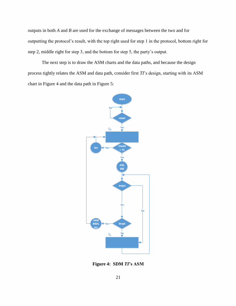
The next step is to draw the ASM charts and the data paths, and because the design
process tightly relates the ASM and data path, consider first TI’s design, starting with its ASM
chart in Figure 4 and the data path in Figure 5:
Figure 4: SDM TI’s ASM

22
mod q
mod q
RegS
D Q
LD
RegS
D Q
LD
mod q
mod q
RegS
D Q
LD
RegS
D Q
LD
Counter
QD
inc
LD
A x B mod q
A
B
A x B mod q
A
B
A + B mod q
A
B
a1
b2
a2
b1
I
a1 seed
b2 seed
a2 seed
b1 seed
clk reset
count00000
inc
Ald
Ald
Bld
Bld
mod q
RegS
D Q
LD
rr seed
Ald
A - B mod q
A
B
A - B mod q
A
B
PRBSseed
R
reset
count
PRBSseed
R
reset
count
PRBSseed
R
reset
count
PRBSseed
R
reset
count
PRBSseed
R
reset
countcount
count
count
count
count
Figure 5: SDM TI’s Data Path
The ASM for TI is simple enough. After the reset, it generates the five random values r,
a1, b1, a2, b2, and after these become available, they are loaded into registers. Then, TI computes
I and sends the corresponding pre-computed randomness to the appropriate party.
On the data path side, we can see several components being used, pseudo-random bit
sequence generators, for example. These, with the help of a counter, produce the five random
values which are then used to calculate their modulus, and then stored in the registers. These
registers, though, are a bit different. A register RegS, as it has been named, is a combination of a
regular register with a multiplexer, to allow for immediate follow through of the input value.
RegS, and all other components are described in Appendix A. This permits the increment of the
23
throughput by cutting a clock cycle from the total cycles needed. Also, note that the counter
receives its load signal directly from reset. This can be done because the ASM ensures that 32
increments are taken, bring the initial value back to 0 when TI is required again.
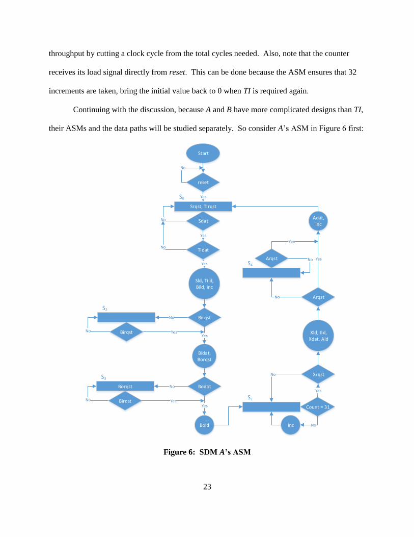
Continuing with the discussion, because A and B have more complicated designs than TI,
their ASMs and the data paths will be studied separately. So consider A’s ASM in Figure 6 first:
Start
reset
No
Srqst, TIrqst
Yes
S0
Sdat
Yes
Tidat
No
Sld, Tild, Bild, inc
Yes
BirqstNo
S0
No
S2
BirqstNo
Bidat, Borqst
YesYes
BodatBorqst No
S3
No Birqst
Bold
Count = 31YesYes
inc No
S1
Xrqst
Yes
No
Xld, tld, Xdat. Ald
Arqst
Adat,inc
S4
Arqst No
No
Yes
Yes
Figure 6: SDM A’s ASM

24
Although it may seem complicated or convoluted at first, if follows the simple step-by-
step the protocol follows when using a 32-bit prime number q. A must first obtain the values it
needs for the protocol, that is the pre-distributed randomness from TI and the shares from the
users. So that is the purpose of S0’s initial part, requesting TI’s data and the users’ shares that
correspond to A, and A will continue to request the data it needs before moving on. If it is the
case that A receives the required inputs, then it proceeds to load that data to its registers and keep
track of the number of clock cycles that have occurred since it also needs to generate randomness
for step 3. After A stores the values, it checks if B has requested the values it needs to send to B
for step 1, going to another state, S2, if B did not signal a request and staying in that state until B
does so. On the other hand, if at any of the rising edges of the clock B requests the data from
step 1, then A continues and asserts Bidat (valid bit for B’s input as seen by A) to let the other
party know that the values being sent are valid. As A asserts Bidat, it also requests B’s output
from step 2 by a signaling high on Borqst. This let’s B know that it is ready to receive step 2’s
data. In a similar manner to before, A now has to check whether B has send those values by
asserting Bodat. In the case the data is not ready, A goes to state S3, where it continues to request
and check for valid data, and as soon as valid data is available, A loads it into a register, and
moves on to state S1, where it will continue to generate the remaining random bits it needs. In
this state, a counter is continually incremented until 31, meaning that 32 clock cycles have
occurred, so A is ready to compute the values from step 3. So after t is ready, A checks if B has
requested X’s value, returning to state S1 if not, and loading X, t, and its output to registers, while
also signaling to B that X is ready to be read. Next, still within S1, A verifies whether its output
has been requested. If it has, then it signals the validity of the data by asserting Adat and it
increments the counter once more so that it is set back to 0. If it was the other way, when A’s

25
output has not yet been requested, then the ASM goes to another state named S4, where it
continues to wait for a request for its output. When its output is requested, it transitions to S0 to
complete the execution of the protocol.
So that is the gist of A’s ASM chart. Please notice how even though it seems convoluted
at first, it follows a logical train of thought, as previously explained, for state transitioning and
output asserting. Now it is time to look at the final part of A’s ASM design, which is the data
path shown in Figure 7, and just as with the ASM, the data path also tries to follow intuition and
logical reasoning. For example, on the left side, all inputs can be observed, each going in to a
RegS. This, again, is done to save one clock cycle so that maximum throughput may be
achieved. Also, signals that are outputted by the ASM are present here like Sld, TIld, and so on.
Now that the ASM has been studied, looking at the data path should be more intuitive. In
the first step, transitioning from S0 to S1, all the relevant values are loaded into the input register
on the left and the output register for B on the right. From what it was seen in Figure 6, it is
known that the top six input registers can be loaded with uA, a1, vA, b1, V2 and U2, and the top
two output registers with U1 and V1, in the first clock cycle after the reset, provided that B is
functioning normally. To be more precise, note that because all values are ready in the same
clock cycle, the outputs, U1 and V1, can also be calculated right away using the "A-B mod q"
components, and sent out by signaling high on Bidat at the same time, as long as B requests data
using Birqst of course, due to RegS's special loading capability. In the same manner, on step 2,
the inputs U2 and V2 can be loaded right away because they are loaded into RegS components.
During step 3, A needs to generate t to compute X, so it uses an up-counter to count 32 clock
cycles, and after the randomness is the calculations X1 = (vB − b2) a1, X2 = (uB − a2) b1 and X =
(uAvA + X1 + X2 − t) can be made. Since A requires more clock cycles to generate t, the other

26
party can either keep their own counter of how many clock cycles have passed or can simply
request X repeatedly until it becomes valid. The latter turns out to be the best option not only
because it eliminates the need for more circuitry to have a counter and the logic to figure out
when B should request the data, but the former option would require both A and B to have the
same clock speed, which may not be true in many cases. Moreover, since input values are
maintained by the registers, loading X right away is not needed until it is requested with Xrqst, so
the request signal for X is simply used as the load value for X's RegS. However, because B
knows of A’s extra time spent generating randomness, B is requesting for X constantly and just
waiting for valid data (more on this shortly), so in practice, Xdat is signaled as high at the same
clock cycle as when t is ready and X is calculated. Also, during the same clock cycle t is ready,
A can be calculated and loaded, but for the same reason as X, it does not need to be loaded until
the output is requested.

27
RegS
D Q
LD
RegS
D Q
LD
RegS
D Q
LD
RegS
D Q
LD
uA
a1
vA
b1
A - B mod q
A
B
A - B mod q
A
B
uAi
vAi
U1
V1
RegS
D Q
LD
RegS
D Q
LD
V2
U2
A x B mod q
A
B
A x B mod q
A
B
A x B mod q
A
B
A + B mod q
A
B
X
a1i
b1i
A + B mod q
A
B
A - B mod q
A
B
Counter
QD
inc
LD
00000
inc
PRBSseed
R
reset
count
count
count
t seedmod q
RegS
D Q
LDRegS
D Q
LD
ti
r
A + B mod q
A
B
RegS
D Q
LD
RegS
D Q
LD
RegS
D Q
LD
RegS
D Q
LD
ri
A
Note: clk and reset wires not show in this drawing
Sld
Sld
Tild
Tild
Tild
Birqst
Birqst
Xrqst
Bodat
Bodat
reset
reset
tld
Ald
Figure 7: SDM A’s Data Path

28
Now that TI and A’s designs have been fully explained, all that is left from the SDM
protocol’s design that needs to be discussed is B’s ASM design, starting with its ASM chart in
Figure 8 and then finishing with its data path in Figure 9. Following the same logic as with A’s
ASM, this ASM chart starts with a necessary reset so that the initial state is known, and then
continues to follow the clear steps presented in the protocol itself. First, B must have its share of
U and its share of V, along with the pre-distributed randomness a2, b2, and I, from TI, but also
notice that Aorqst is also a Moore output in state S0. This is a simplification done because it does
not matter if A’s output from step 1 is ready at the same time as the shares and pre-distributed
randomness due to the fact that its value will not be loaded unless uB, vB, a2, b2, and I are valid
as well, and clearly, if Sdat and TIdat are not high, then there is no transition to another state. Of
course, when this data is valid, the B’s output from step two can be computed and store right
away by signaling Aild. In the case that U1 and V1 are not indicated to be valid by Aodat, then
the ASM moves to state S1. In S1, the ASM continues to make requests for U1 and V1 until the
values become valid. When Aodat is high, then Aold is asserted and B checks whether U2 and
V2 have been requested with Airqst. If Airqst is not high, then the next state is S2, where B waits
until these values are requested by A. When U2 and V2 are requested, then step 2 from the
protocol can be completed by signaling to A that the values are valid using Aidat, and also, to
request X with Xrqst. If X is not available yet, then the ASM transitions to S3, where it continues
to request X until the data is valid. Next, when Xdat becomes 1, then X can be loaded with Xld,
so B’s final output can be calculated now that X is valid and it can be loaded using Bld. Lastly, B
checks for a request on its final output using Brqst. If Brqst is not asserted, then the ASM goes
to state S4 to continually checks for a request. In either case, when the request is received, B

29
asserts Bdat to indicate its output is valid, and it returns to S0, completing a full execution of the
protocol.
Next, consider B’s data path. As with A’s data path, registers used for inputs are located
on the left, and registers used for outputs are located on the right. In addition, all these registers
are RegS components to eliminate extra clock cycles. Regarding its functionality, it can be
observed that registers are organized in such a way that calculations from the steps in the
protocol can be followed from top to bottom. On the top, the registers for uB, a2, vB, and b2 are
found, and they continue to the "A-B mod q" components that calculate U2 and V2, which are the
first computations that B needs to perform. The next four registers, corresponding to X, I, U1,
and V1, are used to store other input values needed to calculate Y1 = (uA−a1) vB = U1 vB and Y2
= (vA−b1) uB = V1 uB, and B’s output Y = (Y1 + Y2 + X + uBvB + I). This calculations,
however, need not be done until X is valid. So when X in indicated as valid by Xdat, X is loaded
and available immediately, and B’s output is calculated using the several "A+B mod q" and "A
×B mod q" components.
As mentioned previously, it is crucial for optimality that this protocol is design to achieve
maximum throughput because the other two protocols use this one repeatedly, which is why
emphasis has been made in making it clear that ASMs will request and send multiple pieces of
data at the same time, and data paths will use RegS in sequential circuits to eliminate extra clock
cycles because this type of register ties the input directly to the output when a new value is being
loaded into a regular register contained within itself. This way, on the first clock cycle when its
load signal is 1, the output is taken directly from the input, and for the following clocks, it is
taken from its regular register component.

30
Start
reset
No
Srqst, Tirqst, Aorqst
YesS0
Sdat
TIdat
Yes
Sld, Tild, Aild
Yes
Aodat
No
No
Aorqst
S1
No
Aold
AodatYes
YesNo
Airqst
S2
No
Aidat, Xrqst
AirqstYes
YesNo
XdatXrqst
S3
No
Xld, Bld
XdatYes
YesNo
Brqst
No
S4
Bdat
Brqst
Yes
Yes
No
Figure 8: SDM B’s ASM

31
RegS
D Q
LD
RegS
D Q
LD
RegS
D Q
LD
RegS
D Q
LD
uB
a2
vB
b2
A - B mod q
A
B
A - B mod q
A
B
uBi
vBi
RegS
D Q
LD
U2
RegS
D Q
LD
V2
RegS
D Q
LD
RegS
D Q
LD
RegS
D Q
LD
RegS
D Q
LD
X
I
V1
U1
A x B mod q
A
B
A + B mod q
A
B
A x B mod q
A
B
A x B mod q
A
B
A + B mod q
A
B
A + B mod q
A
B
A + B mod q
A
B
Register
D Q
LD
Bout
Note: clk and reset wires not show in this drawing
Sld
Sld
Tild
Tild
Tild
Aold
Aold
Xdat
Aild
Aild
Bld
Figure 9: SDM B’s Data Path
Note: all components are reviewed in more detail in Appendix A.

32
2.1.3. Protocol Complexity and ASM Throughput
In this section, the interest lies in finding the complexity in relation to a security
parameter. This parameter is the size of the prime number q, which is what provides the
computational security for the protocol. So as mentioned in the previous section, q is 32 bits, but
for a more general solution, let |q| denote the bit length of q.
As it can be seen, neither the original protocol nor the slightly modified version which
was implemented have a complexity dependent on |q|, giving a complexity of O(1) for number
of multiplications and additions, and with O(|q|) for generating randomness. Moreover, the
maximum TPC of the protocol should be 1/|q| = 1/32 because input data is loaded in 1 clock
cycle and it takes |q| = 32 cycles to complete the computation of the multiplication. It is worth
noting that ASMs should be design to reach the max TPC possible, which in the case of these
designs, it is true.
Due to generating randomness on step 3 of the SDM protocol, the throughput of both A,
and B is 1/|q| = 1/32 because 1 multiplication can be done in the 32 clock cycles it takes to
generate a random number. TI’s throughput because it generates one output set of values every
32 clock cycles. Note that when the protocol runs the first time, it takes 64 clock cycles to
calculate the multiplication; however, this is just a transient because TI continues to generate
random numbers, so that when new randomness is requested again, it is available right away.
The TPC diagrams for TI, A, and B are in Figure 10:

33
S0 S1
30
b. A TPC diagram
S0 S3
30
c. B TPC diagram
S1
32
a. TI TPC diagram
Figure 10: SDM TPC Diagrams
2.1.4. Protocol Modification for Hardware
As mentioned before, a slight change was made to the original protocol in order to add
simplicity to the VHDL design. This change is simply to replace subtractions with additions of
additive inverses. In Zq, additive inverses can be easily calculated by subtracting said number
from q. For example, in step 1, A must calculate (uA - a1), so this operation is replaced by (uA +
(q − a1)). This is done for each subtraction in steps 1, 2, and 3. Furthermore, the reasoning
behind this change is to avoid the usage of signed data types in the VHDL code, because using
that data type would require extending numbers to one extra bit in order to prevent data losses.
Note that the result of any of those subtractions could, in fact, be negative, which does not result
in any errors after computing the modulo q when using signed numbers, but it does, however,
create an obvious error when only using unsigned numbers.
2.1.5. VHDL Implementation Details
To implement each party’s hardware, two different approaches are taken for the ASM
and the data path. All parties use a component-based implementation to describe the data path,
whereas for the ASM, TI uses a dataflow implementation, and A and B use an algorithmic

34
implementation. The reason for this is because TI requires much less complicated hardware so
state and output equations can be easily derived from its ASM, but A and B have more
complicated algorithms to run, making it simpler, from an implementation perspective, to use a
“process” to describe each of those ASMs. In all cases, the ASM’s current state is stored in D
Flip-Flop implemented using an algorithmic approach, with a synchronous, active high, reset.
Furthermore, to implement A and B’s ASMs a new type is declared to represent the states. These
states are used in a process that resets all outputs to 0 first to avoid latching, and then in a case
statement the process contains, each case represents a state where only the appropriate signals
are set to 1. Using a process is very helpful for one important reason, which is that states only
assert the signals they are supposed to, just like they do in the ASM chart itself.
The SDM design, which includes TI, A, and B, was implemented using a very popular
tool named Quartus II, which is used for FPGA and system on chip (SoC) design, so it works
nicely with VHDL. From Quartus, it is simple to make use of VHDL packages like
IEEE.STD_LOGIC_1164 to allow usage of std_logic_vector, IEEE.STD_LOGIC_UNSIGNED
to allow the usage of addition, subtraction, and multiplication of standard logic vectors, and
IEEE.NUMERIC_STD in order to be able to use the unsigned data type, as well as addition,
subtraction, and multiplication of the unsigned type. Finally, after having designed the entities
and architectures for TI, A, and B, another design, called SDM_chip, is used to connect all three
parties. This SDM_chip uses the parties' designs as components to perform a simple port
mapping to interconnect them, yielding the report in Table 1 after analysis and synthesis in done
on SDM_chip. The most important detail to observe from the report provided by Quartus is that
the large majority of logic elements used are part of combinational logic, which is to be expected

35
since all addition, subtraction, multiplication, and modulus functions are calculated for 32-bit
words, creating the need for the large amount of logic elements.
The SDM_chip, the top-level architecture of the SDM Quartus project, which contains all
three parties hooked up together, is then assessed using a testbench, also written in VHDL, which
provides the clock, reset, and the inputs like uA, uB, vA, and vB to the parties. Essentially, this
testbench runs the protocol under the security model’s assumption and verifies its proper
functionality by calculating the expected and obtained results, and comparing these results to
show they are equal.
Table 1: SDM Analysis and Synthesis Report from Quartus II
Total logic elements 31,315
Total combinational functions 31,187
Dedicated logic registers 1,140
Total registers 1140
Total pins 202
Total virtual pins 0
Total memory bits 0
Embedded Multiplier 9-bit elements 64
Total PLLs 0
Note: all VHDL code is available in Appendix B.
2.1.6. Sample Run
ModelSim-Altera was the CAD tool used for simulating the hardware implementation.
The verification is done by writing a VHDL testbench that is complemented with a macro file to
configure the simulation itself. Put simply, the testbench dictates the behavior of each signal like
the clock, reset, and inputs, and the macro file tell ModelSim-Altera what to display and what
format to use for the displayed variables.
The simulation runs for three sets of inputs, and with q = 4294967291, also, all
operations in modulo q. First, however, the parties must wait until pseudo-randomness is

36
generated to output meaningful data. The testbench was written to reset the hardware and then
make each set of inputs available as soon as they are requested, which is right after the reset.
After the first set of randomness is provided, the protocol starts running normally.
Moreover, note that the set of inputs in the testbench were changed at the same time the new set
of randomness is available to allow for a clean transition that can be seen in the ModelSim-
Altera simulation output.
In each iteration, the values shown are reset, clk, uA, uB, vA, vB, Arqst, Ao, Adat, Brqst,
Bo, Bdat, mult1, mult2, and correct. Note that uA, vA, uB, and vB are A and B's additive shares
of U and V. Also, Arqst and Brqst are the request signals corresponding to Ao and Bo, which are
the parties' outputs, respectively. In addition, mult1 is equal to (uA + uB) (vA + vB), and mult2 is
equal to (Ao + Bo). So by the output correctness property, mult1 should equal mult2 when Adat
and Bdat are both 1, since these are the data signals for Ao and Bo. When the expected result,
mult1, and the obtained result, mult2, are equal, correct is high, and otherwise is low.
The first set of inputs are uA = 1906243613, uB = 1761250485, vA = 1450887487, and
vB = 991888945, so the two numbers are U = 3667494098 and V = 2442776432. The result
gives that mult1 = mult2 = 333301357. The second set of inputs are uA = 1073741827, uB = 1,
vA = 1, and vB = 1, so the two numbers are U = 1073741828 and V = 2. The result gives that
mult1 = mult2 = 2147483656. The third set of inputs are uA = 3, uB = 2, vA = 5, and vB = 8, so
the two numbers are U = 5 and V = 13. The result gives that mult1 = mult2 = 65, showing the
protocol works.
To illustrate these results, Figure 11 shows the simulation results directly obtained from
ModelSim-Altera, where red lines and the value “U” represents an uninitialized value, 0s and 1s

37
show the value of a vector (a variable with more than one bit), and high and low represent 1 and
0, respectively, for single bit variables like reset and clk.
Figure 11: SDM Sample Run
2.2. Secure Distributed Multiplication of a Sequence (PiSDM)
Secure Distributed Multiplication of a Sequence is a protocol where two servers, using
additive shares, can compute the “pi product” of several numbers, without knowing what the
original numbers are. This protocol, although not explicitly introduced in [1] as it is presented in
this thesis, still is important because it is used in the Secure Comparison protocol described. In

38
step 3 of SC, PiSDM is used even though it is not presented separately, but as a part of Secure
Comparison. The next section explains the protocol in detail.
2.2.1. Original Protocol
The protocol PiSDM works similarly to SDM with one big difference: the parties A and B
don’t receive two shares of two separate numbers, but multiple shares corresponding to the bits
in a bit string c, where cA refers to A’s array of shares, and cB refers to B’s array shares. So each
share is an additive share of a bit in c. These arrays are indexed from 1 to l = |q| because of the
protocol’s end use in SC, where the shares of index 1, for example, are written as c1A and c1B.
Using these shares, TI, A, and B run the protocol in the following manner. Let l be the
number of bits in c, i the current index in the arrays cA and cB, Ai and Bi the SDM outputs for i =
2…l, and with the assumption that one set of precomputed random values from TI is available
like it is done in the SDM protocol, then:
Step 1: A and B run SDM with c1A, c1B, c2A and c2B as inputs with the precomputed values
from TI, and TI generates new randomness for the next step. Set i = 2 so that A2 and B2
denote the SDM result in this iteration.
Step 2: increase i by 1. A and B run SDM with ciA, ciB, Ai-1 and Bi-1 as inputs with the
precomputed values from TI, and TI generates new randomness for the next step. The
outputs are Ai and Bi.
Step 3: repeat Step 2 until i = l.
Step 4: A outputs Aout = Al and B outputs Bout = Bl.
Output Correctness: assume the Aout = Al and Bout = Bl are not correct. Then there must
exist some i for which Ai and Bi are also not correct, but this cannot be the case because the
inputs initial input c1A, c1B, c2A and c2B give a correct output due to SDM’s correctness. So by the

39
same assumption, no i exist such that Ai and Bi are not correct, and therefore, Aout and Bout must
be correct.
Moreover, the intuition behind the security proof is simple. By the
Composability Theorem, it is secure to combine protocols in series, provided that the combined
protocols are secure on their own. So by this theorem, our (l – 1) iterations of SDM are secure,
making PiSDM secure.
2.2.2. ASM Design
Continuing with the PiSDM discussion, it will be shown that even though this protocol
computes a more difficult result than SDM, with the use of the SDM parties’ components, the
resulting ASM design is much less complicated, and therefore also showing the biggest
advantage of hierarchical design approaches. So much like how it was done with SDM, consider
the parties’ interfaces in Figure 12:

40
PiSDM A
TIrqstr
a1
b1
TIdat
Crqst
C
Cdat
AoutArqst Adat
BirqstU1
V1Bidat
Xrqst
XXdat
BorqstU2
V2Bodat
PiSDM TIArqst
r
a1
b1
Adat
Brqst
I
a2
b2
Bdat
PiSDM B
TIrqstI
a2
b2
TIdat
Crqst
C
Cdat
BoutBrqst Bdat
AorqstU1
V1Aodat
Xrqst
XXdat
AirqstU2
V2Aidat
a. TI interface
b. A interface c. B interface
Figure 12: PiSDM Interfaces
The same concept and intuition that applied to SDM, applies here with PiSDM. Request
and data signals are named in such a way as to indicate which parties are communicating for the
particular value they enclose. For example, TI has Arqst, an input, and Adat, an output,
enclosing r, a1, and b1, indicating that these values from TI will be sent A. The case of X is a bit

41
different. X, which is a single piece of data sent from A to B, simply has the same port names in
both A and B to illustrate the fact that these ports are to be connected, where Xrqst in A is an
input, but it is an output in B, and X and Xdat are outputs for A, but inputs for B.
With the interfaces explained, now consider the requirements for TI. The fact is that TI
just needs to be able to generate the randomness needed by A and B, and continue to do so until
they are done running the SDM protocol (l – 1) times. If SDM’s TI is looked at carefully, it can
be deduced that it meets the requirements this TI needs. This is true because SDM’s TI will
generate randomness whether it is requested or not, and once it has come up with r, a1, b1, I, a2,
and b2, it will check if A or B have requested their values. The first time around, A and B will
wait for TI to compute their values. After that, while they are running SDM, TI continues to
generate more randomness, and by the time the parties require a new set of random values from
TI, it has already computed them. So please refer to the section 2.1.2 for details about PiSDM
TI’s design.
As explained in the previous paragraph, the PiSDM protocol gets its TI design for free
from SDM, and although it does not quite get A and B for free, the additions are not too
complicated. Not only that, but A’s design and B’s design turn out to be identical because they
are just repeatedly querying SDM A and SDM B, respectively. So taking A as an example,
consider its ASM first. Note that after the reset, it asserts Crqst, uAs which is a select signal, and
Cpld, a parallel load signal in state S0. The next step is to check whether C is valid by checking
if Cdat is high. If it is not, then the ASM loops back to S0, but if it is, then it can load C and the
count using countld (keeping track of how many times it has run the SDM protocol is obviously
necessary since it has to stop eventually, so that is why there is a count variable). A also checks
if ASrqst is high, meaning that SDM A has requested shares. If SDM A hasn’t, then the next state
42
is S2, where it waits for a request. When a request is made, though, A signals ASdat to let the
SDM component know that the given shares are valid and uses uAld, another load signal, to use
the correct index of C for step 1 on PiSDM. When this is done, it sets the next state to S1.
Step 2 in the protocol is slight different that step 1, creating the need for S1 and S3, which
roughly perform the same checks and asserts similar variables as S0 and S2, respectively, with
one important addition being that both S1 and S3 now keep track of the count to make sure to
transition to the right state when the count has been reached. To be more specific, S1 is designed
to check first if the count has been reached, and if it has not, it asserts ASdat indicating that SDM
A’s input shares are valid and proceeds to request its output. If the output is not ready yet, then
the ASM returns to S1, but when it is, the ASM performs another check to see if the count is 30
because in that case, it would mean that the current output is the last one, so A can assert inc and
check if the PiSDM output has been requested with Arqst, asserting Adat and returning to S0 if it
has, and returning to S1. If it is not the last iteration, the count is increased, and the values for the
next round are loaded, and ASrqst is immediately checked to see if ASM A has requested new
shares. If it has requested shares, then it simply returns to S1, but otherwise, it transitions to S3.
In state S3, as with S1, the count is checked first to see if it has reached the final iteration. If it
hasn’t then it checks if SDM A is done generating the current iteration’s output, increasing the
count and loading the next values if it has, or returning to S3 if it hasn’t. If it is the case that the
ASM is currently in S3 and the last iteration has been reached, A checks if the Arqst is high,
asserting Adat if the output has been requested, or returning to S1 if it has not been requested.

43
Start
reset
No
Crqst, uAs, Cpld
Yes
S0
Cdat
Yes
ASrqst
No
Yes
S0
S2
Cld countld
ASdat uAld
S1
No ASrqst
No
ASdat uAld
Yes
count = lArqst
No
Yes
AdatAld
Yes
ASdat AArqst
No
AAdat
inc Cld
uAld
count = l
AAdat
No no
Yes
No
ASrqst
No
inc Cld
uAld
Yes
Yes
S3
count = l - 1
No
Yes
inc Yes
Figure 13: PiSDM A’s ASM

44
The reason why count is checked twice is to reduce one clock cycle when the last
iteration is reached because if it was not done this way, then one cycle would be wasted
unnecessarily transitioning from S1 to S3, and then checking if the final output has been
requested. This way, as soon as the output is available, it Arqst is used to transition to S0 or S1.
To complete A’s design, the last step is to look at its data path in Figure 14:
SDM A
TIrqstr
a1
b1
TIdat
Srqst
uAvASdat
AoutArqst Adat
BirqstU1
V1Bidat
Xrqst
XXdat
BorqstU2
V2Bodat
RegSD Q
LD
ShiftRegPQD
LD
pLD
C2...C32
Cld
Cpld
0
1C1
uAld
ASdat
ASrqst
TIdat
Birqst
Borqst
b1
a1
r
TIrqstU1
V1
Bidat
X
Xrqst
Xdat
U2V2
Bodat
AArqst AAdat
uAs
Aout
Counter
QD
inc
LD
00000
inc
count
countld
RegSD Q
LDAld
Figure 14: PiSDM A’s Data Path
So as previously stated, PiSDM A (and B) is not much more complicated than SDM A. It
requires a counter to keep track of how many iterations of SDM it has gone through, a mux used
to distinguish between the first iteration (step 1), and all the following iterations (step 2), so with
the help of the ASM, uAs connects C1 to the RegS that provides uA to SDM A when the state is
S0, and selects the value coming as feedback from SDM A’s output for the rest of the iterations.
45
The last hardware component used is ShiftRegP, a special shift register which also has a parallel
load option. This is used to load C2 through Cl at the same time into the data path, and then feed
the values one by one to SDM A.
There is one more difference here related to how the counter is used here, though.
Because the PiSDM protocol needs (l − 1) iterations of SDM, then for the required l bit words, (l
– 1) iterations are needed. So simply initializing the count to 0s and counting to (l – 1) works
nicely.

46
Start
reset
No
Crqst, uBs, Cpld
Yes
S0
Cdat
Yes
BSrqst
No
Yes
S0
S2
Cld countld
BSdat uBld
S1
No BSrqst
No
BSdat uBld
Yes
count = lBrqst
No
Yes
BdatBld
Yes
BSdat BBrqst
No
BBdat
inc Cld
uBld
count = l
BBdat
No no
Yes
No
BSrqst
No
inc Cld
uBld
Yes
Yes
S3
count = l - 1
No
Yes
inc Yes
Figure 15: PiSDM B’s ASM

47
RegSD Q
LD
ShiftRegPQD
LD
pLD
C2...C32
Cld
Cpld
0
1C1
uBld
BSdat
BSrqst
TIdat
Aorqst
Airqst
b2
a2
I
TIrqstU1
V1
Aodat
X
Xrqst
Xdat
U2V2
Aidat
BBrqst BBdat
SDM B
TIrqstI
a2
b2
TIdat
Srqst
uBvBSdat
BoutBrqst Bdat
AorqstU1
V1Aodat
Xrqst
XXdat
AirqstU2
V2Aidat
SDM B
TIrqstI
a2
b2
TIdat
Srqst
uBvBSdat
BoutBrqst Bdat
AorqstU1
V1Aodat
Xrqst
XXdat
AirqstU2
V2Aidat
uBs
Counter
QD
inc
LD
00000
inc
count
countld
BoutRegS
D Q
LDBld
Figure 16: PiSDM B’s Data Path
Figure 15 and Figure 16 show B’s design. Since it was mentioned that this party’s design
is identical to A’s, then no further explanation will be made at this point about B’s ASM and data
path.
2.2.3. Protocol Complexity and ASM Throughput
PiSDM has a complexity easy to calculate simply because it queries SDM repeatedly,
giving it a complexity of O(l − 1) = O(l) in big-O notation for multiplications and additions, and
O(l × |q|) for generating randomness.
ASM throughputs are easy to calculate as well. TI has the same throughput as SDM TI
since they are the same design, and A and B query their corresponding SDM party l − 1 times, to
obtain one output so each of their throughputs is:

48
𝑇𝐶𝑃 =1
(32)(𝑙 − 1)
This can be observed from their TCP diagrams in Figure 17. In addition, TCPmax is also
the same as A and B’s TCP by inspection of the protocol. So all parties achieve max throughput.
S0 S1
32 (l — 1)
b. A TPC diagram
S0 S1
32 (l — 1)
c. B TPC diagram
S1
32
a. TI TPC diagram
Figure 17: PiSDM TPC Diagrams
2.2.4. VHDL Implementation Details
In this implementation, TI remains the same, and A and B use the SDM parties’
implementation in a component-based data path implementation, with an algorithmic (process)
approach to the ASM, much like it was done in SDM. The packages used are the same with the
addition of a custom package named MY_PACKAGE, which defines a useful data type, an array
basically, to describe the multitude of shares A and B receive from the user. It makes it easier for
whomever is writing the VHDL code since VHDL is a hard-typed language, meaning that inputs
and outputs must have the same data types as required by their declaration as a signal or an input
or output pin in the component’s entity. This is the case because arrays are a bit more
complicated to declare, so defining a new data type removes a lot of the kinks that come from
that.

49
To combine all the parties and test the protocol as a whole, the component PiSDM_chip is used,
where TI, PiSDM A, and PiSDM B are connected to run in the same why as in SDM_chip, using
the parties’ implementations as components and connecting them together. The component
PiSDM_chip is later used in the testbench tb_pisdm, which provides the clock, reset, input
signals to the PiSDM protocol running in VHDL. When providing the input, this testbench
follows the OCDDC, validating the inputs with each party’s data signal and requesting their
output right away, and continuing to request the outputs until both parties A and B have signaled
that their corresponding results are valid.
Quartus II’s analysis and synthesis gives the report given in Table 2. This is the result of
synthesizing PiSDM_chip, so the whole protocol. The most important detail to notice about this
report is that comparing the total number of logic elements between PiSDM_chip and SDM_chip,
the former is not much larger than the latter. This confirms the intuition of the PiSDM design,
which, analogously, is not much bigger than the secure distributed multiplication design.
Furthermore, another number to take a note of is the total number of pins (both input and output
pins), which might be alarming, but not necessarily since PiSDM is to be used by SC, which can
define its own input method to reduce the number of pins.
Table 2: PiSDM Analysis and Synthesis Report from Quartus II
Total logic elements 32,830
Total combinational functions 32,766
Dedicated logic registers 3,270
Total registers 3270
Total pins 2,122
Total virtual pins 0
Total memory bits 0
Embedded Multiplier 9-bit elements 64
Total PLLs 0

50
2.2.5. Sample Run
PiSDM is actually somewhat generic in the sense that the number of multiplications can
be set using a VHDL generic map, so this example uses 32-bit shares. This protocol, however,
does not have the restriction of using shares that add up to bits (either 0 or 1), so because this
restriction will lead to the result almost always being 0 and being 1 only for the case when all
bits are 1, non-zero numbers larger than one are used. These numbers are all 2 except for the
first one which is 1, and the reason why these were chosen for the sample run is because the
result is easy to recognize (231
= 100000000000000000000000000000002).
The testbench mentioned before is used by the ModelSim-Altera and the written macro
file to simulate the protocol. In this simulation, the values shown are reset, clk, Arqst, Ao, Adat,
Brqst, Bo, Bdat, expected, and calculated. The signals Arqst and Brqst are the request signals for
PiSDM A and B’s outputs, and Adat and Bdat are the corresponding valid data signals. Ao and
Bo show the iteration’s output, so that the last value is the final result. The other two signals
show the expected and calculated results. A partial view of the simulation is in Figure 18:
Figure 18: PiSDM Sample Run
As it can be seen, Adat and Bdat indicate the validity of the output, which can be
confirmed by comparing the expected and calculated variables, which are the same from the
moment both data signals are shown as high.

51
2.3. Secure Comparison (SC)
The secure comparison is a protocol executed between two parties, which use additive
shares of two numbers' bits and abstract mathematics to be able to compare two integers modulo
q, and tell whether one is larger than the other without ever knowing the two numbers
themselves. This protocol is the final design presented in this thesis, and is built upon the
previous designs already discussed.
2.3.1. Original Protocol
The protocol SC utilizes PiSDM, along with some other computations that use abstract
mathematics, in order to determine whether a number Y = (yl... y1) is greater than another number
X = (xl... x1). This is a two party protocol between A and B, where each them has additive shares
of the X and Y’s bits. These shares are represented by A’s XA = (xlA... x1A), YA = (ylA... y1A), and
B’s XB = (xlB... x1B), YB = (ylB... y1B). In this way, xi = xiA + xiB and yi = yiA + yiB, where these
additive shares belong to Zq, and xi, yi belong to the binary numbers. Also, let square brackets [ ]
enclosing a variable denote the shares of said variable. For example, [xi] represents the shares of
xi, both xiA and xiB, that is. Note that q > 2l+2
is a requirement stated by the authors.
The protocol, as presented by the authors, goes as stated bellow, with A having XA and
YA, and B having XB and YB, and outputting Y > X or Y ≤ X:
Step 1: for i = 1… l, A and B compute shares [di] where di = xi – yi. Note di ∈ {0, 1, -1}.
Step 2: for i = 1… l, A and B compute shares [ci] where ci = di + 1 + ∑ 𝑑𝑗2𝑙−𝑗+2𝑙
𝑗=𝑖+1 .
Step 3: A and B query SDM l – 1 times in order to compute the shares of Out =
∏ 𝑐𝑖𝐴 + 𝑐𝑖𝐵𝑙𝑖=1 . The first iteration computes c1c2, and then recursively multiply that by ci.
Let OutA and OutB be the shares which correspond to Out.

52
Step 4: B sends OutB to A, so that A can compute Out = OutA + OutB. If Out = 0, then A
outputs Y > X, otherwise, A outputs Y ≤ X.
Before reading about the security of the protocol, some helpful intuition is discussed
regarding the protocol correctness. The first point to notice is the meaning of the di variables in
step 1, which can be simply consider the “difference bits”. This is used to know which bits are
different between X and Y. On the next step, the “comparison bits” are computed. These
comparison bits, starting from bit 1, compute a summation that will only be 0 when all the
remaining bits to the left are 0 (the bits which are more significant). The reason to do this is
because a bit i is relevant to the output only when the remaining significant bits are the same in X
and Y. Take bit l, for example, there are no bits that are no more significant that this one, so ci =
di + 1. In this case, ci = 0 only when di is -1, implying yi > xi. This leads to step 3. Taking
advantage of SDM, A and B can multiply all of these shares securely, and so only when one
comparison bit is 0 is when Y is greater than X, otherwise, the result will always be non-zero as
long as q > 2l+2
. This is a requirement because of the 2l – j +2
in Step 2, which can overflow the
modulus q, possibly causing a false positive. Later, it will be shown that the q > 2l+2
restriction
can be tighten up in order to gain another bit of resolution for X and Y. For a full correctness
proof, see [1].
Now that some intuition has been given to the reasoning behind the protocol’s operations,
consider the security of SC, which can be taken into three parts. The first one is the first two
steps of the protocol, which are simply internal computations of random numbers, leaving no
issue there. The second part is step 3, where SDM is recursively called, so as it was pointed out
in the PiSDM section, there is no security risk in serially querying a protocol which is secure on
its own. This leaves the last part to be step 4, where B sends its output to A. In this case, there
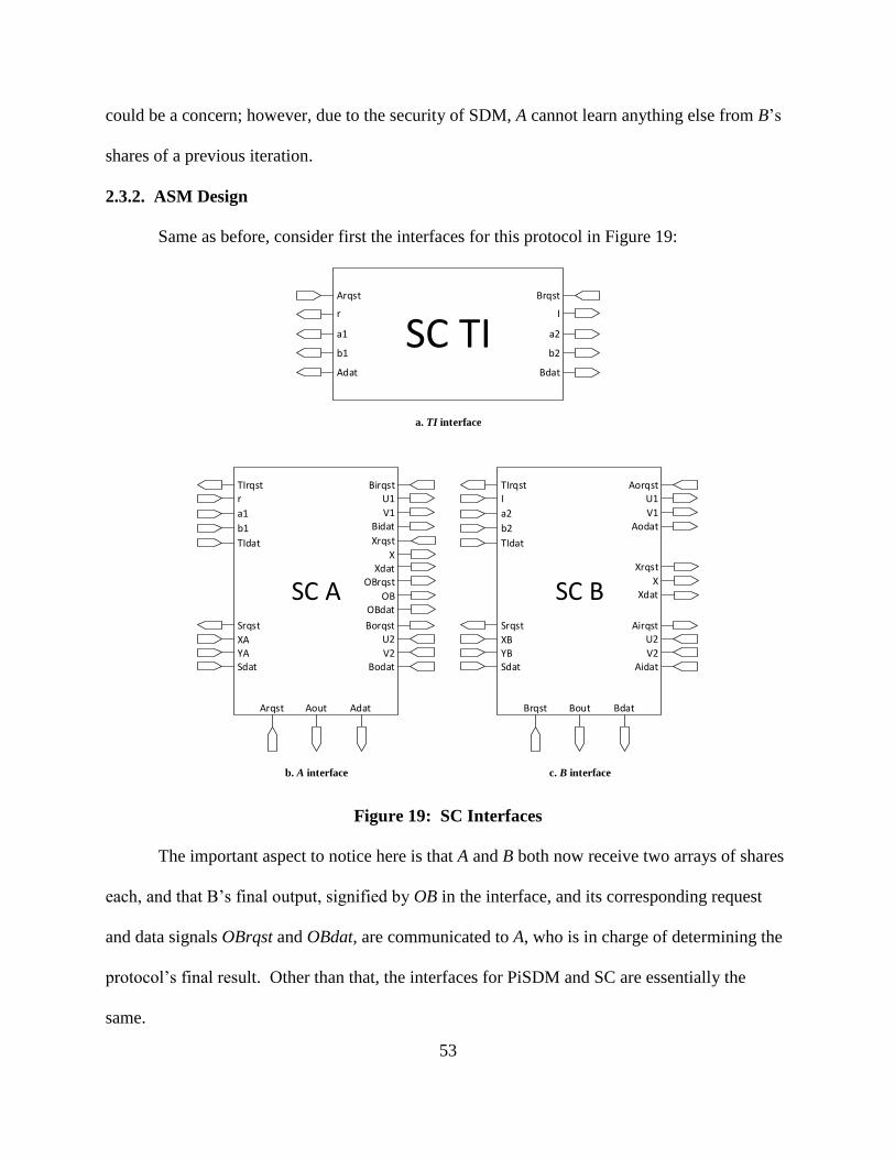
53
could be a concern; however, due to the security of SDM, A cannot learn anything else from B’s
shares of a previous iteration.
2.3.2. ASM Design
Same as before, consider first the interfaces for this protocol in Figure 19:
SC TIArqst
r
a1
b1
Adat
Brqst
I
a2
b2
Bdat
SC A
TIrqstr
a1
b1
TIdat
Srqst
XAYASdat
AoutArqst Adat
BirqstU1
V1Bidat
Xrqst
XXdat
BorqstU2
V2Bodat
OBrqst
OBOBdat
a. TI interface
b. A interface c. B interface
SC B
TIrqstI
a2
b2
TIdat
Srqst
XBYBSdat
BoutBrqst Bdat
AorqstU1
V1Aodat
Xrqst
XXdat
AirqstU2
V2Aidat
Figure 19: SC Interfaces
The important aspect to notice here is that A and B both now receive two arrays of shares
each, and that B’s final output, signified by OB in the interface, and its corresponding request
and data signals OBrqst and OBdat, are communicated to A, who is in charge of determining the
protocol’s final result. Other than that, the interfaces for PiSDM and SC are essentially the
same.

54
Unlike PiSDM, though, secure comparison does have different designs for A and B
because they perform different kinds of computations in the protocol, although they are
somewhat similar, and TI remaining the same as SDM and PiSDM. First, consider A’s ASM in
Figure 20.
After the state machine goes through reset, A first checks if the shares XA and YA are
available and valid, then it checks if PiSDM A has requested a set of shares to perform the secure
distributed multiplication of all shares in that set. If the input shares XA and YA have not been
indicated to be valid, or if shares have not been requested by PiSDM A, then the next state is
simply S0. Otherwise, ACdat is set to high, indicating the PiSDM component that shares
provided to it are valid, and the next state is S1. Note that the computations of steps 1 and 2 are
combinational, so values for step 3 can be ready as soon as the input shares are read in. After
PiSDM A has received the necessary shares, then SC A requests the sequential product output
repeatedly in S1 using AArqst, and checking the validity of the output with AAdat. In this case, it
is known that A will remain in S1 for the several clock cycles it will take for the PiSDM protocol
to complete, which corresponds to step 3, but after AAdat is a 1, then the step is complete, so SC
A can request B’s output for step 4. To do that, A asserts OBrqst to request OutB, and verifies
whether OBdat is asserted.
At this point, two more states remain to discuss. The first one, S2, is used as a safeguard
for when OutB is not valid right away in S1. State S2 simply requests OutB until OBdat is a 1,
indicating the value is valid. Regardless of whether the state transition occurred directly from S1,
or just from S2, Bld is asserted so that A loads OutB as an input. After this value is loaded, then
A can finalize its computations and final output from step 4. So Arqst is checked to see if the
final output has been requested. This leads to the last state to discuss, S3. This state is similar to

55
S2 in the sense that it is used as a safeguard for when values are not requested as soon as they are
available, or when requested values are not yet valid. In this state, Arqst is constantly checked,
remaining in S3 until the output is requested by the user, and again, regardless of where the state
transition came from, as soon as Arqst is 1, then Adat is asserted to indicate the final output is
valid, and the state goes back to S0.
Since A and B’s ASMs are similar, now consider B’s ASM in Figure 21. It can be seen
that after the reset, B requests its shares XB and YB, and checks if PiSDM B has requested input
shares for calculate the Pi product. If both of those are true, BCdat is asserted and the ASM
transitions to S1, but otherwise, the ASM stays in S0. While at S1, the ASM requests PiSDM B’s
output constantly with BBrqst until the output is signified to be valid with a 1 in BBdat. Since B
does not perform any more computations, it loads its output OutB into a register using Bld, and
waits until the output is requested by SC A. To do that, Brqst is checked, transitioning to S2
when the value was not requested by A. When the output is requested, though, whether the ASM
is currently in S1 or S2, Bdat is asserted to let SC A know that OutB is correct, and state goes back
to S0.

56
Start
reset
No
Srqst
YesS0
Sdat
ACrqst
Yes
ACdat
Yes
No
No
AArqst
S1
OBrqst
AAdatNo
OBdat OBrqst
S2
No
Bld
OBdat
Yes
No
Arqst
S3No
Arqst No
Yes
Bld
Yes
Adat
Yes
Yes
Figure 20: SC A’s ASM

57
Start
reset
No
Srqst
YesS0
Sdat
BCrqst
Yes
BCdat
Yes
No
No
BBrqst
S1
BBdatNo
Brqst
S2No
Brqst No
Yes
Bdat
Yes
Yes
Figure 21: SC B’s ASM
Following to A and B’s data paths, there are only a few differences. The first one is that
on step 2, the parties must compute ci = di + 1 + ∑ 𝑑𝑗2𝑙−𝑗+2𝑙
𝑗=𝑖+1 , where the shares for the
summation and di can be easily computed, so the only remaining computation is to add the 1. To

58
do this, an arbitrary party alone can add a 1 to their computed [di]. Party B is selected arbitrarily
to carry out this extra addition. This leads to A’s data path in Figure 22 and B’s data path in
Figure 23.
SubShares
A
B
SigmaSharesD
ACdat
ACrqst
TIdat
Birqst
Borqst
b1
a1
r
TIrqstU1
V1
Bidat
X
Xrqst
Aout
U2V2
Bodat
AArqst AAdat
XA
YA
RegSD Q
LD
PiSDM A
TIrqstr
a1
b1
TIdat
Crqst
C
Cdat
AoutArqst Adat
BirqstU1
V1Bidat
Xrqst
XXdat
BorqstU2
V2Bodat
AddShares
A
B
A + B mod q
A
B
Comparator
A
A = 0
OB
Bld
Xdat
Figure 22: SC A’s Data Path

59
SubShares
A
B
SigmaSharesD
AddShares1
A
B BCdat
BCrqst
TIdat
Aorqst
Airqst
b2
a2
I
TIrqstU1
V1
Aodat
X
Xrqst
Xdat
U2V2
Aidat
BBrqst BBdat
Bout
PiSDM B
TIrqstI
a2
b2
TIdat
Crqst
C
Cdat
BoutBrqst Bdat
AorqstU1
V1Aodat
Xrqst
XXdat
AirqstU2
V2Aidat
XB
YB
Figure 23: SC B’s Data Path
From these two figures, the important components to observer are the “Shares”
components. Subshares receives two arrays of shares, and subtracts the bottom array from the
top one, AddShares adds the shares instead of subtracting, AddShares1 adds the shares with the
extra plus 1 from step 2, and SigmaShares calculates the sigma summation also from step 2. The
output from step 2 comes from the AddShares component in A, and the AddShares1 component
in B. This result is fed directly to the corresponding PiSDM component to carry out step 3. The
remaining components are to calculate and hold the final result in step 4, which by the way, is
represented by a single bit. When Y > X, the output is a 1, or a 0 for Y ≤ X. Notice the use of
RegS for maximized throughput.
2.3.3. Protocol Complexity and ASM Throughput
SC is an example where the complexity and the throughput vary with respect to each
other just because of the massive amounts of additions and multiplications done on top of the
usage of PiSDM. The complexity, in terms of addition and subtractions is O(l + l2) because l
come from PiSDM and l2 comes from the summation in step 2, which can be reduced if the

60
summation is performed differently. To be precise, if the summation is calculated from i = l
down to i = 1, then the previous summation value can be reused, reducing the l2 to simply l,
giving a final complexity of O(l). The same applies to multiplications, which are reduced as well
if the previous approach is taken to calculate ∑ 𝑑𝑗2𝑙−𝑗+2𝑙
𝑗=𝑖+1 , giving O(l) as well. Lastly, in
terms of generating randomness, complexity is O(l × |q|) because PiSDM is queried l − 1 times.
As for ASM throughputs, all parties remain with the same TCP and TCP diagrams
because the only sequential component is any SC party is the corresponding PiSDM component,
so TI has the same throughput as PiSDM TI, and A and B have the following TCP value:
𝑇𝐶𝑃 =1
(32)(𝑙 − 1)
This can be observed from their TCP diagrams in Figure 24:
S0 S1
32 (l — 1)
b. A TPC diagram
S0 S1
32 (l — 1)
c. B TPC diagram
S1
32
a. TI TPC diagram
Figure 24: SC TPC Diagrams
2.3.4. Optimizing l and Selecting q for the Biggest Integer Range
The restriction q > 2l+2
comes from the need to use an extra 22 in step 2’s summation.
When considering the possible values for the expression for c1 = d1 + 1 + ∑ 𝑑𝑗2𝑙−𝑗+2𝑙
𝑗=2 , which
has the most terms in the sigma sum, we have that its maximum absolute value is

61
| ∑ 𝑑𝑗2𝑙−𝑗+2|𝑙
𝑗=2 = |𝑑22𝑙 + 𝑑32
𝑙−1 +⋯+ 𝑑𝑙22| ≤ 2𝑙+1 − 4, making safe to assume a q > 2
l+2.
However, note that a false positive can only occur when ci is some multiple of q, and given the
fact that | ∑ 𝑑𝑗2𝑙−𝑗+2|𝑙
𝑗=2 is always even, then the only case that any ci could be a multiple of q is
when di + 1 is 1, giving the range 5 − 2𝑙+1 ≤ ci ≤ 2𝑙+1 − 3, which contains 2𝑙+2 − 7 distinct
values. Note that the actual upper bound is ci ≤ 2𝑙+1 − 2, but this occurs when di = 1, which will
result in an even-valued ci, and that will never result in 0 when the modulo-q operation is carried
out because q is an odd prime. The number of values in the range is the actual minimum
boundary (non-inclusive) for q, so that overflow in the modulo-q operation is never possible. So
now that it is known that the exact inequality is q > 2l+2
– 7, q (and l) can be selected, and as it
has been used before, let q = 4294967291. This selection is actually quite good because q =
4294967291 = 2l+2
– 5 for l = 30, giving a nearly perfect q value for a length of 30 (recall l is X
and Y’s length, or their number of bits). Having |q| = 32 is good choice by itself already because
is a power of two, which would make it easier to adapt the design for use in many processors.
Furthermore, another reason why using a 32-bit prime q is a good choice is because it is the
maximum number of bits allowed that will still permit the usage of standard VHDL packages
and operations, mainly because the modulus operation can only be performed to numbers of up
to 64-bits, and since multiplication is required, 32-bit buses are the maximum allowed for regular
variables like shares and so on. Finally, in order to have the maximum domain for which X and
Y belong to, the obvious selection is the closest prime to 232
-1, which is the largest value
contained in 32 bits. Finding such prime number is easy with the powerful mathematical engine
WolframAlpha [33], yielding the result q = 4294967291.
62
2.3.5. VHDL Implementation Details
The last item to discuss before seeing SC in the works is the protocol’s implementation in
VHDL. So first off, since TI remains the same, no discussion is needed, but just keep in mind
that the implementation is done using a dataflow approach for its ASM, and component-based
for the data path. On the other hand, A and B’s implementation do have to be looked at because
even though they take the same approach as in the other protocols, the designs are different, so a
few packets that were not required in PiSDM, for example, are required here again. Mainly
IEEE.STD_LOGIC_UNSIGNED for of addition, subtraction, and multiplication of standard
logic vectors, and IEEE.NUMERIC_STD to use the unsigned numbers, as well as addition,
subtraction, and multiplication of the unsigned type. This packet is needed again because of the
SubShares, AddShares, AddShares1, and SigmaShares components, which require these basic
modular operations. Another noteworthy remark is the usage of generics and generates
statements in order to simplify the otherwise tedious implementation of the SigmaShares
component used in step 2 of the protocol. These kind of statements, represented by the “generic”
and “generate” keywords, are used to programmatically describe the components in the hardware
rather than explicitly declaring every single one of them. Another case where generics and
generates are useful is for the implementation of the shift register with parallel load used by
PiSDM (Seen Appendix A for component design and Appendix B for component VHDL
implementation). Furthermore, each party has their own entity and architecture, providing again
the abstraction and isolation required from a security application.
To test the protocol as a whole, however, the parties’ implementations are used as
components in a single chip in the sc_chip.vhd file. In this chip, TI, A, and B are wired up and
connected in the proper manner. The sc_chip is then used as a component in the testbench,

63
tb_sc.vhd. This test bench supplies inputs, clock, reset, and complies with the OCDDC. In order
to provide the inputs, two more packages are used in the testbench, which are tb_Xshares and
tb_Yshares. Since these packets include the additive shares for X and Y, respectively, a tool was
developed in C to generate these shares from the input numbers. So these packets are
automatically written by a C program which takes in the desired values for X and Y, and writes
.vhd files containing said VHDL packages. The details and code for this C program can be
found in Appendix C.
The compilation report given for analysis and synthesis for the sc_chip high-level
architecture is shown in Table 3:
Table 3: SC Analysis and Synthesis Report from Quartus II
Total logic elements 168,168
Total combinational functions 168,168
Dedicated logic registers 3,180
Total registers 3180
Total pins 3,849
Total virtual pins 0
Total memory bits 0
Embedded Multiplier 9-bit elements 408
Total PLLs 0
From this report, it is important to note the large amount of logic elements. The reason
why PiSDM, when compared to SDM, does not use that many logic elements is because the
remaining logic used by PiSDM besides SDM itself are mostly registers and a mux. In the case
of SC, though, a lot more combinational logic is added by the usage of the share computation
components SubShares, AddShares, AddShares1, and SigmaShares, with SigmaShares
representing the largest amount of circuitry added mainly because of the multiplications. After
the sigma summations hardware, SubShares is the one that requires the second largest amount of
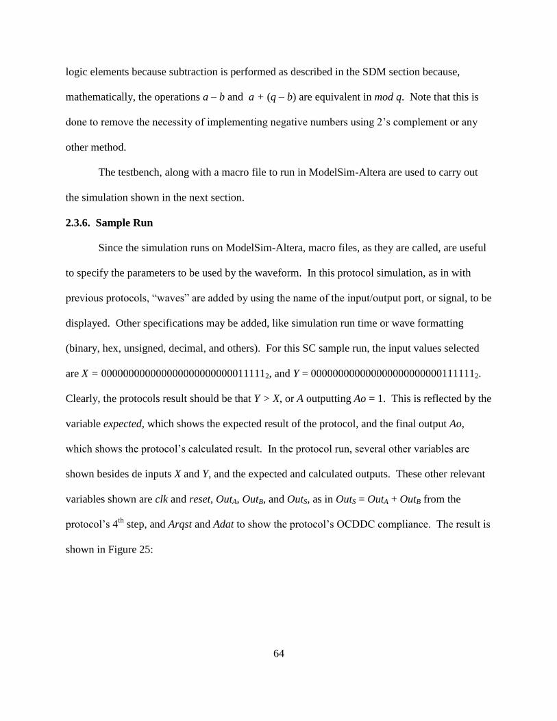
64
logic elements because subtraction is performed as described in the SDM section because,
mathematically, the operations a – b and a + (q – b) are equivalent in mod q. Note that this is
done to remove the necessity of implementing negative numbers using 2’s complement or any
other method.
The testbench, along with a macro file to run in ModelSim-Altera are used to carry out
the simulation shown in the next section.
2.3.6. Sample Run
Since the simulation runs on ModelSim-Altera, macro files, as they are called, are useful
to specify the parameters to be used by the waveform. In this protocol simulation, as in with
previous protocols, “waves” are added by using the name of the input/output port, or signal, to be
displayed. Other specifications may be added, like simulation run time or wave formatting
(binary, hex, unsigned, decimal, and others). For this SC sample run, the input values selected
are X = 0000000000000000000000000111112, and Y = 0000000000000000000000001111112.
Clearly, the protocols result should be that Y > X, or A outputting Ao = 1. This is reflected by the
variable expected, which shows the expected result of the protocol, and the final output Ao,
which shows the protocol’s calculated result. In the protocol run, several other variables are
shown besides de inputs X and Y, and the expected and calculated outputs. These other relevant
variables shown are clk and reset, OutA, OutB, and OutS, as in OutS = OutA + OutB from the
protocol’s 4th
step, and Arqst and Adat to show the protocol’s OCDDC compliance. The result is
shown in Figure 25:
65
Figure 25: SC Sample Run

66
3. PROPOSED GENERAL METHOD TO DESIGN AND IMPLEMENT
CRYPTOGRAPHIC HARDWARE
From Section 2, a pattern can be derived to generalize the process of designing and
implementing a cryptographic protocol in hardware and tie everything together into one method
(Note that the same ideas can be applied to designing and implementing schemes).
First, identify modules which require privacy from each other. In the case of the
previously described protocol, the different modules are the parties TI, A, and B.
Second, by studying the protocol, determine what values are internal, what the inputs are
and what the outputs of each party are. This is necessary to construct the interface and
know the variables that might be involved in the data path and ASM. Note that more
variables may be necessary, but this narrows it down.
Third, using the I/Os found in the previous step, draw the parties’ interfaces following the
OCDDC. Note that although it is not necessary, it is encouraged that inputs that can be
read in at the same time are group together under the same request and data signals, and
the same is recommended for the outputs, because it will reduce the next state logic.
Since several inputs might be required for one computation, not grouping them will
create more states which will be required for when inputs are not available. The same
occurs with the outputs, requiring more states if those outputs are not grouped under the
same request and data signals.
Lastly, after the different modules have been identified and the interfaces have been
clearly defined, use the ASM design approach to engineer a data path and an ASM for
each of the modules while complying with OCDDC.

67
The end design can be implemented in VHDL easily by using a component-based
approach to describe the data path, and al algorithmic approach (process-based) to describe the
ASM. Please note that ASMs can also be implemented as a dataflow, resulting in a more
economical implementation space-wise, but at the cost of bigger efforts on the engineer’s side.

68
4. RESULTS AND CONCLUSIONS
4.1. Results
From the compilation reports in section 2, tables 1, 2, and 3, the SDM and the PiSDM
protocols can be synthesized into fairly low-end FPGAs like a few members of the Cyclone IV
family. The following models can comfortably be used for synthesizing SDM and PiSDM from
the Cyclone IV E list of devices: EP4CE40, EP4CE55, EP4CE75, and EP4CE115, and from the
Cyclone IV GX list, these devices can also be used: EP4CGX50, EP4CGX75, EP4CGX110, and
EP4CGX150 [12]. The Cyclone IV E and GX list of devices offer low power and high
functionality for the most cost-effective prices with list E, and GX offering extra features. From
the given selection of device, the lowest amount of logic elements (LEs) is 39,600, which will
suffice to synthesize the 31,315 LEs in SDM, and the 32,830 LEs in PiSDM. For the SC
protocol, a higher-capacity FPGA would be needed, like the Cyclone V GX C9 and GT D9 with
301,000 LEs [32], which is more than sufficient for the necessary 168,168 LEs to synthesize the
SC protocol.
Regarding timing results, the following is shown, in Table 4, about the SC protocol's
Python implementations from [11]:
Table 4: SC Python Timing Results
Times in seconds SC A SC B
Run 1: 3.51677 3.51672
Run 2: 2.00958 2.00957
Run 3: 3.52951 3.52925
Average: 3.01862 3.01851
These timing results were obtained in an Intel i7 2.2 GHz processor running Windows 7
with 8 GB of RAM. Just by comparison, the SC hardware implementation runs with a 100 MHz

69
clock, and even with this slower clock, the protocol still completes in 9,865,000 ps = 9.865 µs.
This is a speed up, on average, of roughly 306,000 times, proving one of the main
accomplishments presented in this thesis.
4.2. Conclusions
Since protocols are more complicated than schemes because they involve the exchange of
messages between two or more parties, the design of cryptographic protocols in hardware has not
yet been thoroughly studied, with this being the first academic research known to the author.
Protocols, however, are more powerful than schemes and can achieve more complicated and
significant results. So for these reasons, it was the purpose of this thesis to further breach the gap
between digital hardware and cryptography by tackling this very interesting problem using the
algorithmic state machine design approach, considering each party as a separate module, creating
the abstraction and privacy desired for the aforementioned protocols of Secure Distributed
Multiplication (SDM), Secure Distributed Multiplication of a Sequence (PiSDM), and finally,
Secure comparison (SC), and all while following the One Cycle Demand Driven Convention
(OCDDC) for inter module communication purposes. In addition to using the ASM design
approach and following the OCDDC, the presented designs achieved maximum throughput with
the usage of the RegS component (a register and a mux that result in the output being ready right
away when a value is loaded), and also by taking inputs and providing the output early, which is
done with a combination of using RegS components and properly placing Moore and Mealy
outputs in the ASM. The correctness of each protocol was verified using VHDL testbenches,
ModelSim-Altera macro files, and ModelSim-Altera itself to execute the written macro files in
order to obtain “wave views” for the protocols. Also, a C project was used to generate input
70
shares for the SC protocol, which requires 60 32-bit shares, making it easier for a future engineer
to run the protocol without having to manually code each share.
From all of the designs, a general method can be deduced, and therefore, suggested for
the implementation of cryptographic protocols (and even schemes) in hardware. First, identify
modules which require privacy from each other (like the parties in a protocol). Second, by
studying the protocol, determine what values are internal, what the inputs are and what the
outputs of each party are. Third, using the I/Os found in the previous step, draw the parties’
interfaces following the OCDDC. Lastly use the ASM design approach to engineer a data path
and an ASM for each of the modules while complying with OCDDC. The end design can be
implemented in VHDL easily by using a component-based approach to describe the data path,
and algorithmic approach (process-based) to describe the ASM.
4.3. Future Work
In the future, there are a few possible ideas brought forward by the results found in this
thesis that are worth exploring. First of all, as the number of LEs needed by the SC protocol is
significant, and not accessible to the lower-end FPGAs, the design can be reduced in size if the
ASM charts are expressed as output and next state logic equations as opposed to the ASM
algorithms described by the charts. Another simplification is the use of logical left shift instead
of multiplication by powers of 2 in the SigmaShares component. The effort is in the hope that
the number of LEs can be brought below the 150,000 count, so that other members of the
Cyclone V family and even some in the Cyclone IV family can synthesize components that large.
Secondly, the next logical step is to remove the trusted initializer. Where the ASM
design approach with OCDDC helps compartmentalize the parties and provide extra privacy with
clock independence between the parties. Trusted initializers have been shown to be removed

71
using the Paillier cryptosystem, or with oblivious transfer, with Paillier being the simpler to
implement solution in hardware, but with high key sizes, and oblivious transfer being harder to
implement, but with a small key size. Both of these approaches are worthy of exploring, and
would both be significant results in the field of cryptography on their own, with the added result
of being able to eliminate TIs in any predistributed multiplication tuples scenario.
Lastly, the design of cryptographic protocols poses an interesting question. How can one
be certain that any cryptographic protocol is fully correct in its execution? In other words, how
is a design like this tested? While this thesis uses case scenarios for testing, a much more
sophisticated approach, which is outside the scope of the thesis, is to use formal verification. In
fact, formal verification of cryptographic protocols is scarce in the literature, making it a very
interesting problem which could have tons of potential benefits to the world of security itself by
eliminating bugs and potential security weaknesses.

72
5. WORKS CITED
[1] B. David, R. Dowsley, R. Katti, and A. Nascimento, “Efficient Unconditionally Secure
Comparison and Private Preserving Machine Learning Classification Protocols,” The
9th
Int Conference on Provable Security, Kanazawa, Japan, 2015.
[2] M. Shand, and J. Vuillemin, “Fast Implementations of RSA Cryptography,” Proc. of the
11th Symp. On Comput. Arithmetic, pp. 252-259, 1993.
[3] S. Dominikus, “A Hardware Implementation of MD4-Family Hash Algorithms,” 9th Int.
Conference on Electronics, Circuits and Systems, Vol 3, pp. 1143-1146, 2002.
[4] P. Kitsos, G. Kostopoulos, N. Sklavos, and O. Koufopavlou, “Hardware Implementation of
the RC4 Stream Cipher,” 46th Midwest Symp. On Circuits and Systems, Vol. 3, pp. 1363-
1366, 2003.
[5] A. Satoh, S. Morioka, K. Takano, and S. Munetoh, “A Compact Rijndael Hardware
Architecture with S-Box Optimization,” Lecture Notes in Comput. Science, Springer, Vol.
2248, pp. 239-254, 2001.
[6] C. Lu, and S. Tseng, “Integrated Design of AES (Advanced Encryption Standard)
Encrypter and Decrypter,” Proc. IEEE Int. Conference on Application-Specific Systems,
Architectures and Processors, pp. 277-285, 2002.
[7] S. Mangard, M. Aigner, and S. Dominikus, “A Highly Regular and Scalable AES
Hardware Architecture,” IEEE Trans. Comput., Vol. 52, no. 4, pp. 483-491, 2003.
[8] S. A. Manavski, “CUDA Compatible GPU as an Efficient Hardware Accelerator for AES
Cryptography,” IEEE Int. Conference on Signal Processing and Commun., pp. 65-68,
2007.
[9] E. Wenger, and M. Hutter, “A Hardware Processor Supporting Elliptic Curve
Cryptography for Less Than 9 kGEs,” Lecture Notes in Comput. Science, Springer, Vol.
7079, pp. 182-198, 2011.
[10] D. Genkin, Y. Ishai, M. Prabhakaran, A. Sahai, and E. Tromer, “Circuits Resilient to
Additive Attacks with Applications to Secure Computation,” Proc. of the 46th Annu. ACM
Symp. On Theory of Computing, pp. 495-504, 2014.
[11] C. A. Nascimento, K. Thompson. Personal Comunication: e-mail.
[12] Altera Corporation, “Cyclone IV FPGA Family Overview,” Table 1-1,
https://www.altera.com/en_US/pdfs/literature/hb/cyclone-iv/cyiv-51001.pdf, 2014.
[13] D. Beaver, “Efficient Multiparty Protocols Using Circuit Randomization,” Lecture Notes
in Comput. Science, Springer, Vol. 576, pp. 420-432, 1992.
[14] Andrew Sheehy, Reuters Sept 4th, 2013. http://www.reuters.com/article/generator-
research-idUSnBw046267a+100+BSW20130904. Seen on Jan 21st 2016.
[15] TekCarta. 2012. http://www.nakono.com/tekcarta/databank/full/28/. Seen on Jan 21st
2016.
[16] G. Mealy, “A Method for Synthesizing Sequential Circuits,” Bell System Technical
Journal 34: 1045–1079, Sept. 1955.
[17] E. Moore, “Gedanken-experiments on Sequential Machines”. Automata Studies, Annals of
Mathematical Studies, Princeton, N.J.: Princeton University Press, 34: 129–153, 1956.
[18] C. Clare, “Designing Logic Systems Using State Machines,” McGraw-Hill 1973, ISBN 0-
07-011120-0.
[19] D. Brown “A State-Machine Synthesizer—SMS”. In Proceedings of the 18th Design
Automation Conference, IEEE Press, Piscataway, NJ, USA, 301-305, 1981.

73
[20] D. Snyers, A. Thayse, “Algorithmic State Machine Design and Automatic Theorem
Proving: Two Dual Approaches to the Same Activity,” in Computers, IEEE Transactions
on, vol.C-35, no.10, pp.853-861, Oct. 1986.
[21] Forrest, and M. D. Edwards, “The Automatic Generation of Programmable Logic Arrays
from Algorithmic State Machine Descriptions,” Proc. of VLSI. Vol. 83, 1983.
[22] S. Smith, and J. Di, “Designing asynchronous circuits using NULL convention logic
(NCL),” Synthesis Lectures on Digital Circuits and Systems4.1: 1-96, 2009.
[23] R. Gennaro, M. O. Rabin, and T. Rabin, “Simplified VSS and fast-track multiparty
computations with applications to threshold cryptography,” Proceedings of the 17th ACM
Symposium on Principles of Distributed Computing (PODC98), pp. 101111, ACM Press,
1998.
[24] R. Cramer, I. Damgård, R. de Haan, “Atomic Secure Multi-Party Multiplication with Low
Communication,” Advances in Cryptology - EUROCRYPT 2007, Lecture Notes in
Computer Science Volume 4515, 2007, pp 329-346, 2007.
[25] P. Lory, “Reducing the complexity in the distributed multiplication protocol of two
polynomially shared values,” In Proceedings of the 21st Int Conference on Advanced
Information Networking and Applications (AINA'2007), volume 1, pages 404-408, IEEE
Computer Society, 2007.
[26] S. Adi, “How to share a secret” Commun. ACM 22, 11 (November 1979), 612-613.
DOI=http://dx.doi.org/10.1145/359168.359176.
[27] P. Lory, “Secure Distributed Multiplication of Two Polynomially Shared Values:
Enhancing the Efficiency of the Protocol,” Emerging Security Information, Systems and
Technologies, 2009. SECURWARE '09. Third International Conference on, vol., no.,
pp.286,291, 18-23 June 2009. doi: 10.1109/SECURWARE.2009.51.
[28] P. Bogetoft, D. L. Christensen, I. Damgård, M. Geisler, T. Jakobsen, M. Krøigaard, ... &
M. Schwartzbach, “Secure multiparty computation goes live,” Financial Cryptography and
Data Security (pp. 325-343). Springer Berlin Heidelberg, 2009.
[29] D. D. Givone, “Digital principles and design,” Dubuque: McGraw-Hill, 2003.
http://catalog.hathitrust.org/api/volumes/oclc/49312747.html.
[30] B. Preneel, and T. Takagi, “Cryptographic Hardware and Embedded Systems,” CHES
2011: 13th International Workshop, Nara, Japan, September 28--October 1, 2011,
Proceedings. Vol. 6917. Springer, 2011.
[31] S. Mangard, and F. Standaert, “Cryptographic hardware and embedded systems,” CHES
2010, 12th international workshop, Santa Barbara, CA, USA, 2010.
[32] Altera Corporation, “Cyclone V Device Overview,” Table 1-1,
https://www.altera.com/content/dam/altera-www/global/en_US/pdfs/literature/hb/cyclone-
v/cv_51001.pdf.
[33] WolframAlpha. WolframAlpha LLC, a Wolfram Research Company, wolframalpha.com.

74
APPENDIX A. COMPONENT DESIGN
This appendix focuses on the design of all the different components used throughout the
protocols’ design. Note that addition, subtraction, multiplication, and modulus are operations
natively supported by VHDL, and are, therefore, not explained any further. Other components
like muxes, counters, and registers are considered to be well-known, so they are assumed to be
understood by the reader.
0
1
RegisterD Q
LD
D
LD
Q
RegSD Q
LD
a. Interface
b. Functionality
Figure A - 1: RegS Component
Figure A - 2: Modular Addition Component

75
Figure A - 3: Modular Subtraction Component
Figure A - 4: Modular Multiplication Component
Figure A - 5: Shift Register with Parallel Load Component
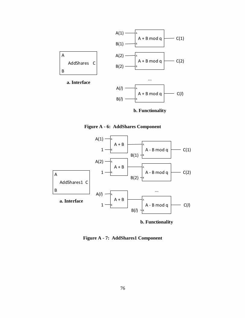
76
AddShares
A
B
a. Interface
A + B mod q
A
B
A + B mod q
A
B
A + B mod q
A
B
...
C
A(1)
B(1)
A(2)
B(2)
A(l)
B(l)
b. Functionality
C(1)
C(2)
C(l)
Figure A - 6: AddShares Component
a. Interface
...
A(1)
B(1)
A(2)
B(2)
A(l)
B(l)
b. Functionality
C(1)
C(2)
C(l)
A - B mod q
A
B
A - B mod q
A
B
A - B mod q
A
B
AddShares1
A
B
C
A + B
A
B
A + B
A
B
A + BA
B1
1
1
Figure A - 7: AddShares1 Component

77
a. Interface...
A(1)
B(1)
A(2)
B(2)
A(l)
B(l)
b. Functionality
SubShares
A
B
C
C(1)
C(2)
C(l)
A - B mod q
A
B
A - B mod q
A
B
A - B mod q
A
B
Figure A - 8: SubShares Component
SigmaShares D DS
a. Interface
A x B mod q
A
B
A + B mod q
A
B
A x B mod q
A
B
DS(31)
D(32)
22
D(31)
23
DS(30)
A x B mod q
A
B
D(31)
24
...
...A + B mod q
A
B
A + B mod q
A
B
A x B mod q
A
B
A x B mod q
A
B2
DS(2)
DS(1)
D(2)
231
b. Functionality
Figure A - 9: SigmaShares Component

78
APPENDIX B. VHDL CODE
Appendix B contains all the VHDL code used in this thesis, including components’ code,
ASM designs, chips, and testbenches.
Components.vhd:
library ieee;
use ieee.std_logic_1164.all;
entity and_5 is
port( A: in std_logic_vector(4 downto 0);
F: out std_logic);
end;
architecture beh of and_5 is
begin
F <= A(4) and A(3) and A(2) and A(1) and A(0);
end;
library ieee;
use ieee.std_logic_1164.all;
entity mux5 is
port( A, B: in std_logic_vector(4 downto 0);
S: in std_logic;
F: out std_logic_vector(4 downto 0));
end;
architecture beh of mux5 is
begin
sel: process(A, B, S)
begin
if S = '1' then
F <= A;
else
F <= B;
end if;
end process;
end;
library ieee;
use ieee.std_logic_1164.all;
entity mux32 is
port( A, B: in std_logic_vector(31 downto 0);
S: in std_logic;
F: out std_logic_vector(31 downto 0));
end;

79
architecture beh of mux32 is
begin
sel: process(A, B, S)
begin
if S = '1' then
F <= A;
else
F <= B;
end if;
end process;
end;
library ieee;
use ieee.std_logic_1164.all;
entity reg5 is
port( X: in std_logic_vector(4 downto 0);
clk, LD: in std_logic;
F: out std_logic_vector(4 downto 0));
end;
architecture beh of reg5 is
begin
reg: process(X, clk, LD)
begin
if clk'event and clk = '1' then
if LD = '1' then
F <= X;
end if;
end if;
end process;
end;
library ieee;
use ieee.std_logic_1164.all;
entity reg32 is
port( X: in std_logic_vector(31 downto 0);
clk, LD: in std_logic;
F: out std_logic_vector(31 downto 0));
end;
architecture beh of reg32 is
begin
reg: process(X, clk, LD)
begin
if clk'event and clk = '1' then
if LD = '1' then
F <= X;
end if;
end if;
end process;
end;

80
library ieee;
use ieee.std_logic_1164.all;
use ieee.std_logic_unsigned.all;
entity count32 is
port( X: in std_logic_vector(4 downto 0);
inc, clk, load: in std_logic;
count: out std_logic_vector(4 downto 0));
end;
architecture beh of count32 is
component reg5
port( X: in std_logic_vector(4 downto 0);
clk, LD: in std_logic;
F: out std_logic_vector(4 downto 0));
end component;
component mux5
port( A, B: in std_logic_vector(4 downto 0);
S: in std_logic;
F: out std_logic_vector(4 downto 0));
end component;
signal X_temp, F_inc, F_temp: std_logic_vector(4 downto 0);
begin
mux: mux5 port map(X, F_inc, load, X_temp);
reg: reg5 port map(X_temp, clk, '1', F_temp);
count <= F_temp;
F_inc <= F_temp + inc;
end;
-- RegSelect
library ieee;
use ieee.std_logic_1164.all;
entity RegS is
port( D: in std_logic_vector(31 downto 0);
clk, load: in std_logic;
Q: out std_logic_vector(31 downto 0));
end;
architecture arch of RegS is
component reg32
port( X: in std_logic_vector(31 downto 0);
clk, LD: in std_logic;
F: out std_logic_vector(31 downto 0));
end component;
component mux32
port( A, B: in std_logic_vector(31 downto 0);

81
S: in std_logic;
F: out std_logic_vector(31 downto 0));
end component;
signal Q_0: std_logic_vector(31 downto 0);
begin
r: reg32 port map(D, clk, load, Q_0);
m: mux32 port map(D, Q_0, load, Q);
end;
-- Shift register with parallel load
library ieee;
use ieee.std_logic_1164.all;
use work.MY_PACKAGE.all;
entity shift_reg_parallel is
generic (N: integer := 31);
port( C: in DATA_ARRAY(1 to N);
clk, LD, pLD: in std_logic;
Q: out std_logic_vector(31 downto 0));
end;
architecture arch of shift_reg_parallel is
component RegS
port( D: in std_logic_vector(31 downto 0);
clk, load: in std_logic;
Q: out std_logic_vector(31 downto 0));
end component;
component reg32
port( X: in std_logic_vector(31 downto 0);
clk, LD: in std_logic;
F: out std_logic_vector(31 downto 0));
end component;
component mux32
port( A, B: in std_logic_vector(31 downto 0);
S: in std_logic;
F: out std_logic_vector(31 downto 0));
end component;
signal reg_in: DATA_ARRAY(1 to N-1);
signal reg_out: DATA_ARRAY(2 to N);
begin
Gen_regs:
for I in 1 to N generate
first:
if I = 1 generate
reg_first: RegS port map(reg_in(I), clk, LD, Q);
end generate; -- first;
middle:

82
if I > 1 and I < N generate
reg_middle: reg32 port map(reg_in(I), clk, LD, reg_out(I));
end generate; -- middle;
last:
if I = N generate
reg_last: reg32 port map(C(N), clk, LD, reg_out(I));
end generate; -- last;
end generate; -- Gen_regs
Gen_muxs:
for I in 1 to N-1 generate
muxes: mux32 port map(C(I), reg_out(I+1), pLD, reg_in(I));
end generate; -- Gen_muxs;
end;
-- SubShares
library ieee;
use ieee.std_logic_1164.all;
use ieee.std_logic_unsigned.all;
use ieee.numeric_std.all;
use work.MY_PACKAGE.all;
entity SubShares is
generic (N: integer := 30);
port( A, B: in DATA_ARRAY(1 to N);
C: out DATA_ARRAY(1 to N));
end;
architecture arch of SubShares is
signal q: unsigned(31 downto 0);
begin
q <= "11111111111111111111111111111011";
Sub: process(A, B, q)
begin
for I in 1 to N loop
C(I) <= std_logic_vector((('0'&unsigned(A(I))) + ('0'&(q -
unsigned(B(I))))) mod q);
end loop;
end process;
end;
-- AddShares
library ieee;
use ieee.std_logic_1164.all;
use ieee.std_logic_unsigned.all;
use ieee.numeric_std.all;
use work.MY_PACKAGE.all;
entity AddShares is
generic (N: integer := 30);
port( A, B: in DATA_ARRAY(1 to N);
C: out DATA_ARRAY(1 to N));
end;

83
architecture arch of AddShares is
signal q: unsigned(31 downto 0);
begin
q <= "11111111111111111111111111111011";
Add: process(A, B, q)
begin
for I in 1 to N loop
C(I) <= std_logic_vector(( ( '0'&unsigned(A(I)) ) + (
'0'&unsigned(B(I))) ) mod q);
end loop;
end process;
end;
-- AddShares1
library ieee;
use ieee.std_logic_1164.all;
use ieee.std_logic_unsigned.all;
use ieee.numeric_std.all;
use work.MY_PACKAGE.all;
entity AddShares1 is
generic (N: integer := 30);
port( A, B: in DATA_ARRAY(1 to N);
C: out DATA_ARRAY(1 to N));
end;
architecture arch of AddShares1 is
signal q: unsigned(31 downto 0);
begin
q <= "11111111111111111111111111111011";
Add: process(A, B, q)
constant one: unsigned(N downto 0) := (0 => '1', others => '0');
begin
for I in 1 to N loop
C(I) <= std_logic_vector( ( one + ('0'&unsigned(A(I))) +
('0'&unsigned(B(I))) ) mod q );
end loop;
end process;
end;
-- Addq
library ieee;
use ieee.std_logic_1164.all;
use ieee.std_logic_unsigned.all;
use ieee.numeric_std.all;
entity Addq is
port( A, B: in std_logic_vector(31 downto 0);
C: out std_logic_vector(31 downto 0));
end;
architecture arch of Addq is
signal q: unsigned(31 downto 0);
begin

84
q <= "11111111111111111111111111111011";
C <= std_logic_vector( ( ('0'&unsigned(A)) + ('0'&unsigned(B)) ) mod q
);
end;
-- Multq
library ieee;
use ieee.std_logic_1164.all;
use ieee.std_logic_unsigned.all;
use ieee.numeric_std.all;
entity Multq is
port( A, B: in std_logic_vector(31 downto 0);
C: out std_logic_vector(31 downto 0));
end;
architecture arch of Multq is
signal q: unsigned(31 downto 0);
begin
q <= "11111111111111111111111111111011";
C <= std_logic_vector( ( unsigned(A) * unsigned(B) ) mod q );
end;
-- SigmaShares
library ieee;
use ieee.std_logic_1164.all;
use ieee.std_logic_unsigned.all;
use ieee.numeric_std.all;
use work.MY_PACKAGE.all;
entity SigmaShares is
generic (N: integer := 30);
port( D: in DATA_ARRAY(1 to N);
DS: out DATA_ARRAY(1 to N));
end;
architecture arch of SigmaShares is
component Multq
port( A, B: in std_logic_vector(31 downto 0);
C: out std_logic_vector(31 downto 0));
end component;
component Addq
port( A, B: in std_logic_vector(31 downto 0);
C: out std_logic_vector(31 downto 0));
end component;
signal SD: DATA_ARRAY(1 to N);
signal M: DATA_ARRAY(1 to N);
signal twos: DATA_ARRAY(2 to N);
signal two: std_logic_vector(31 downto 0);
begin
DS <= SD;
two <= (1 => '1', others => '0');

85
SD(N) <= (others => '0');
twos(2) <= (2 => '1', others => '0');
sigma_gen:
for i in N-1 downto 1 generate
first:
if i = N-1 generate
DS31: Multq port map(D(N), twos(2), SD(N-1));
end generate; -- first
middle:
if i > 1 and i < N-1 generate
twos(N+1-i) <= (twos(N-i)(30 downto 0)) & '0';
Mult: Multq port map(D(i+1), twos(N+1-i), M(i+1));
Add: Addq port map(SD(i+1), M(i+1), SD(i));
end generate; -- middle
last:
if i = 1 generate
Mult1: Multq port map(D(2), twos(N-1), M(2));
Mult2: Multq port map(M(2), two, M(1));
Add: Addq port map(SD(2), M(1), SD(1));
end generate; -- last
end generate; -- sigma_gen
end;
-- Comparator
library ieee;
use ieee.std_logic_1164.all;
entity Comparator is
port( A: in std_logic_vector(31 downto 0);
Aeq0: out std_logic);
end;
architecture behavioral of Comparator is
begin
compare: process(A)
constant zero: std_logic_vector(A'length-1 downto 0) := (others
=> '0');
begin
if A = zero then
Aeq0 <= '1';
else
Aeq0 <= '0';
end if;
end process;
end;
PRBS.vhd:

86
-- Mux
Library IEEE;
use IEEE.std_logic_1164.all;
entity mux2 is
port(S: in std_logic;
X0, X1: in std_logic_vector(4 downto 0);
F: out std_logic_vector(4 downto 0));
end;
architecture BEHAVIOR of mux2 is
begin
mux_behav: process(S, X0, X1)
begin
if S = '0' then
F <= X0;
else
F <= X1;
end if;
end process;
end BEHAVIOR;
-- reg
Library IEEE;
use IEEE.std_logic_1164.all;
entity reg is
port(load: in std_logic;
D: in std_logic_vector(4 downto 0);
clk: in STD_LOGIC;
Q: out std_logic_vector(4 downto 0));
end;
architecture BEHAVIOR of reg is
begin
reg_behav: process
begin
wait until clk'event and clk = '1';
if load = '1' then
Q <= D;
else
null;
end if;
end process;
end BEHAVIOR;
-- prbs_counter
Library IEEE;
use IEEE.std_logic_1164.all;
use IEEE.std_logic_unsigned.all;
use ieee.numeric_std.all;
entity prbs_counter is
port(load: in std_logic; inc: in std_logic;
D: in std_logic_vector(4 downto 0);

87
clk: in STD_LOGIC;
Q: out natural);
end;
architecture BEHAVIOR of prbs_counter is
component reg is
port(load: in std_logic;
D: in std_logic_vector(4 downto 0);
clk: in STD_LOGIC;
Q: out std_logic_vector(4 downto 0));
end component;
component mux2 is
port(S: in std_logic;
X0, X1: in std_logic_vector(4 downto 0);
F: out std_logic_vector(4 downto 0));
end component;
component bit_addressing
port( std_in: in std_logic_vector(4 downto 0);
natural_out: out natural);
end component;
signal D_temp, Q_temp, Q_inc: std_logic_vector(4 downto 0);
begin
mux: mux2 port map(load, Q_inc, D, D_temp);
regist: reg port map('1', D_temp, clk, Q_temp);
Q <= natural(conv_integer(Q_temp));
Q_inc <= Q_temp + inc;
end BEHAVIOR;
-- serial prbs (linear feedback shift register)
Library IEEE;
use IEEE.std_logic_1164.all;
use IEEE.std_logic_unsigned.all;
use ieee.numeric_std.all;
entity prbs is
generic(
BITS : natural := 32);
port(
clk : in std_logic;
reset : in std_logic;
seed : in std_logic_vector(BITS-1 downto 0);
prbs_out : out unsigned(BITS-1 downto 0);
count : in natural);
end;
architecture behavioral of prbs is

88
signal lfsr: std_logic_vector(BITS-1 downto 0); -- Flip-flops with LFSR
state, MSB = BITS
signal outcount: natural;
signal out_temp: unsigned(BITS-1 downto 0);
function feedback(slave : std_logic_vector) return std_logic is --
Function to determine maximum length LFSR generation (XOR taps found online)
begin
case slave'length is
when 3 => return slave( 3) xor slave( 2);
when 4 => return slave( 4) xor slave( 3);
when 6 => return slave( 6) xor slave( 2);
when 8 => return slave( 8) xor slave( 6) xor slave( 5) xor
slave(4);
when 16 => return slave(16) xor slave(15) xor slave(13) xor
slave(4);
when 32 => return slave(31) xor slave(21) xor slave(1) xor
slave(0);
when others => report "feedback function not defined for slave'length
as " & integer'image(slave'length)
severity FAILURE;
return 'X';
end case;
end function;
begin
linear_feedback: process (clk, reset, seed) -- watch list for recomputation
of output pattern
begin
if clk'event and clk = '1' then -- triggers pattern step on clock rising
edge
if reset = '1' then -- Asynchronous reset
lfsr <= seed; -- Reset assigns seed value to full lfsr
signal
else
if unsigned(lfsr) /= 0 then
lfsr <= lfsr(lfsr'left - 1 downto lfsr'right) &
feedback(lfsr); -- Left shift with feedback in, can change order of function
and lfsr concat
-- to perform right shift of values instead
end if;
end if;
end if;
end process;
prbs_out(count) <= lfsr(BITS-1);
end behavioral;
-- 32-bits prbs generator
library ieee;
use ieee.std_logic_1164.all;
use ieee.numeric_std.all;
entity generator is
port( clk, reset: in std_logic;
seed: in std_logic_vector(31 downto 0);

89
prbs_out: out unsigned(31 downto 0));
end;
architecture arch of generator is
component prbs
generic(
BITS: natural);
port(
clk : in std_logic;
reset : in std_logic;
seed : in std_logic_vector(BITS-1 downto 0);
prbs_out : out unsigned(BITS-1 downto 0);
count : in natural);
end component;
component counter
port(load: in std_logic; inc: in std_logic;
D: in std_logic_vector(4 downto 0);
clk: in STD_LOGIC;
Q: out natural);
end component;
signal out_temp: unsigned(31 downto 0);
signal count: natural;
begin
G: prbs
generic map (32)
port map (clk, reset, seed, prbs_out, count);
end arch;
MY_PACKAGE.vhd:
Library ieee;
use ieee.std_logic_1164.all;
package MY_PACKAGE is
type DATA_ARRAY is array (natural range<>) of std_logic_vector(31
downto 0);
end MY_PACKAGE;
SDM_TI.vhd, PiSDM_TI.vhd, SC_TI.vhd:
-- Trusted Initializer Algorithmic State Machine
library ieee;
use ieee.std_logic_1164.all;
use ieee.std_logic_unsigned.all;
use ieee.numeric_std.all;
entity SDM_TI_ASM is
port( clk, reset: in std_logic;

90
Arqst: in std_logic;
r, a1, b1: out std_logic_vector(31 downto 0);
Adat: out std_logic;
Brqst: in std_logic;
I, a2, b2: out std_logic_vector(31 downto 0);
Bdat: out std_logic);
end;
architecture arch of SDM_TI_ASM is
signal q, r_temp, a1_temp, a2_temp, b1_temp, b2_temp, I_temp, a1b2,
a2b1: unsigned(31 downto 0);
signal r_1, a1_1, b1_1, a2_1, b2_1, I_1: std_logic_vector(31 downto 0);
signal count: natural;
signal count_std: std_logic_vector(4 downto 0);
signal D, Qs, C31, inc, Ald, Bld: std_logic;
component prbs_counter
port(load: in std_logic; inc: in std_logic;
D: in std_logic_vector(4 downto 0);
clk: in STD_LOGIC;
Q: out natural);
end component;
component prbs
generic(
BITS: natural);
port(
clk : in std_logic;
reset : in std_logic;
seed : in std_logic_vector(BITS downto 1);
prbs_out : out unsigned(BITS downto 1);
count : in natural);
end component;
component RegS
port( D: in std_logic_vector(31 downto 0);
clk, load: in std_logic;
Q: out std_logic_vector(31 downto 0));
end component;
begin
-- Data Path
q <= "11111111111111111111111111111011";
-- Counter
TI_counter: prbs_counter port map(reset, inc, "00000", clk,
count);
-- PRBS generators
r_gen: prbs generic map (32)
port map(clk, reset,
"00100000101111101100101001110011", r_temp, count);
a1_gen: prbs generic map (32)
port map(clk, reset,
"01110001100111101111100000011100", a1_temp, count);
b1_gen: prbs generic map (32)

91
port map(clk, reset,
"01010110011111000111011011101110", b1_temp, count);
a2_gen: prbs generic map (32)
port map(clk, reset,
"01101000111110101000110010110100", a2_temp, count);
b2_gen: prbs generic map (32)
port map(clk, reset,
"00111011000111110000011000110000", b2_temp, count);
-- Calculate r_1, a1_1, b1_1, a2_1, b2_1, I_1
r_1 <= std_logic_vector(r_temp mod q);
a1_1 <= std_logic_vector(a1_temp mod q);
b1_1 <= std_logic_vector(b1_temp mod q);
a1b2 <= (a1_temp*b2_temp) mod q;
a2b1 <= (a2_temp*b1_temp) mod q;
I_temp <= (("00"&a1b2) + ("00"&a2b1) + ("00"&(q - r_temp))) mod
q;
I_1 <= std_logic_vector(I_temp);
a2_1 <= std_logic_vector(a2_temp mod q);
b2_1 <= std_logic_vector(b2_temp mod q);
-- Registers
r_reg: regS port map(r_1, clk, Ald, r);
a1_reg: regS port map(a1_1, clk, Ald, a1);
b1_reg: regS port map(b1_1, clk, Ald, b1);
I_reg: regS port map(I_1, clk, Bld, I);
a2_reg: regS port map(a2_1, clk, Bld, a2);
b2_reg: regS port map(b2_1, clk, Bld, b2);
-- ASM
count_std <= std_logic_vector(to_unsigned(count, 5));
C31 <= count_std(0) and count_std(1) and count_std(2) and
count_std(3) and count_std(4);
D <= (Qs or C31) and (Arqst nand Brqst);
Ald <= (not Qs) and C31;
Bld <= Ald;
inc <= ( (not Qs) and (not C31) ) or (Arqst and Brqst);
Adat <= (Qs or C31) and Arqst and Brqst;
Bdat <= (Qs or C31) and Arqst and Brqst;
-- DFF (State)
sync: process
begin
wait until clk'event and clk = '1';
if reset = '1' then
Qs <= '0';
else
Qs <= D;
end if;
end process;
end;
-- Pi product TI Algorithmic State Machine
library ieee;
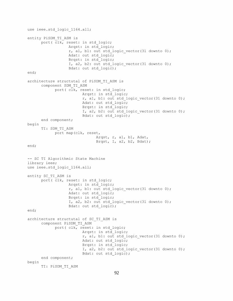
92
use ieee.std_logic_1164.all;
entity PiSDM_TI_ASM is
port( clk, reset: in std_logic;
Arqst: in std_logic;
r, a1, b1: out std_logic_vector(31 downto 0);
Adat: out std_logic;
Brqst: in std_logic;
I, a2, b2: out std_logic_vector(31 downto 0);
Bdat: out std_logic);
end;
architecture structutal of PiSDM_TI_ASM is
component SDM_TI_ASM
port( clk, reset: in std_logic;
Arqst: in std_logic;
r, a1, b1: out std_logic_vector(31 downto 0);
Adat: out std_logic;
Brqst: in std_logic;
I, a2, b2: out std_logic_vector(31 downto 0);
Bdat: out std_logic);
end component;
begin
TI: SDM_TI_ASM
port map(clk, reset,
Arqst, r, a1, b1, Adat,
Brqst, I, a2, b2, Bdat);
end;
-- SC TI Algorithmic State Machine
library ieee;
use ieee.std_logic_1164.all;
entity SC_TI_ASM is
port( clk, reset: in std_logic;
Arqst: in std_logic;
r, a1, b1: out std_logic_vector(31 downto 0);
Adat: out std_logic;
Brqst: in std_logic;
I, a2, b2: out std_logic_vector(31 downto 0);
Bdat: out std_logic);
end;
architecture structutal of SC_TI_ASM is
component PiSDM_TI_ASM
port( clk, reset: in std_logic;
Arqst: in std_logic;
r, a1, b1: out std_logic_vector(31 downto 0);
Adat: out std_logic;
Brqst: in std_logic;
I, a2, b2: out std_logic_vector(31 downto 0);
Bdat: out std_logic);
end component;
begin
TI: PiSDM_TI_ASM
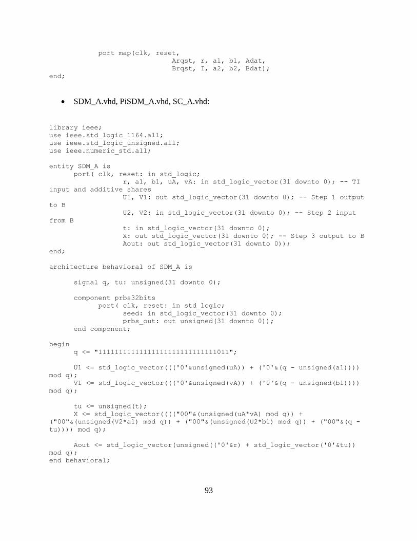
93
port map(clk, reset,
Arqst, r, a1, b1, Adat,
Brqst, I, a2, b2, Bdat);
end;
SDM_A.vhd, PiSDM_A.vhd, SC_A.vhd:
library ieee;
use ieee.std_logic_1164.all;
use ieee.std_logic_unsigned.all;
use ieee.numeric_std.all;
entity SDM_A is
port( clk, reset: in std_logic;
r, a1, b1, uA, vA: in std_logic_vector(31 downto 0); -- TI
input and additive shares
U1, V1: out std_logic_vector(31 downto 0); -- Step 1 output
to B
U2, V2: in std_logic_vector(31 downto 0); -- Step 2 input
from B
t: in std_logic_vector(31 downto 0);
X: out std_logic_vector(31 downto 0); -- Step 3 output to B
Aout: out std_logic_vector(31 downto 0));
end;
architecture behavioral of SDM_A is
signal q, tu: unsigned(31 downto 0);
component prbs32bits
port( clk, reset: in std_logic;
seed: in std_logic_vector(31 downto 0);
prbs_out: out unsigned(31 downto 0));
end component;
begin
q <= "11111111111111111111111111111011";
U1 <= std_logic_vector((('0'&unsigned(uA)) + ('0'&(q - unsigned(a1))))
mod q);
V1 <= std_logic_vector((('0'&unsigned(vA)) + ('0'&(q - unsigned(b1))))
mod q);
tu <= unsigned(t);
X <= std_logic_vector(((("00"&(unsigned(uA*vA) mod q)) +
("00"&(unsigned(V2*a1) mod q)) + ("00"&(unsigned(U2*b1) mod q)) + ("00"&(q -
tu)))) mod q);
Aout <= std_logic_vector(unsigned(('0'&r) + std_logic_vector('0'&tu))
mod q);
end behavioral;

94
library ieee;
use ieee.std_logic_1164.all;
use ieee.numeric_std.all;
entity SDM_A_ASM is
port( clk, reset: in std_logic;
TIrqst: out std_logic; -- TI request: randomness
r, a1, b1: in std_logic_vector(31 downto 0); -- randomness
TIdat: in std_logic; -- TI data valid
Srqst: out std_logic; -- Shares request
uA, vA: in std_logic_vector(31 downto 0); -- Shares
Sdat: in std_logic; -- Shares valid
Birqst: in std_logic; -- Step1 data request from B
U1, V1: out std_logic_vector(31 downto 0); -- Step1 output
to B
Bidat: out std_logic; -- Step1 data valid to B
Borqst: out std_logic; -- Step2 data request to B
U2, V2: in std_logic_vector(31 downto 0); -- Step2 input
from B
Bodat: in std_logic; -- Step2 data valid from B
Xrqst: in std_logic; -- Step3 data request from B
X: out std_logic_vector(31 downto 0); -- Step3 output to B
Xdat: out std_logic; -- Step3 data valid to B
Arqst: in std_logic; -- Step4 request for output
Aout: out std_logic_vector(31 downto 0); -- Party A output
Adat: out std_logic); -- Step4 output valid
end;
architecture arch of SDM_A_ASM is
component RegS
port( D: in std_logic_vector(31 downto 0);
clk, load: in std_logic;
Q: out std_logic_vector(31 downto 0));
end component;
component prbs_counter
port(load: in std_logic; inc: in std_logic;
D: in std_logic_vector(4 downto 0);
clk: in STD_LOGIC;
Q: out natural);
end component;
component prbs
generic(
BITS : natural := 32);
port(
clk : in std_logic;
reset : in std_logic;
seed : in std_logic_vector(BITS-1 downto 0);
prbs_out : out unsigned(BITS-1 downto 0);
count : in natural);
end component;
component SDM_A
port( clk, reset: in std_logic;
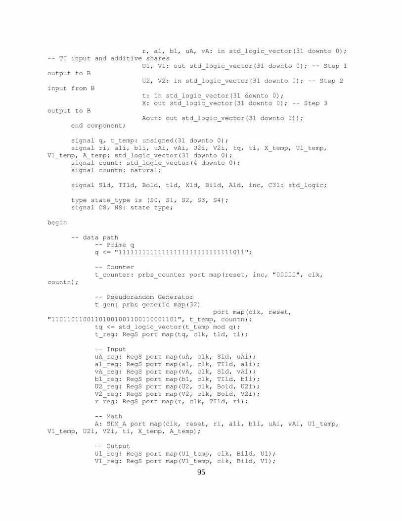
95
r, a1, b1, uA, vA: in std_logic_vector(31 downto 0);
-- TI input and additive shares
U1, V1: out std_logic_vector(31 downto 0); -- Step 1
output to B
U2, V2: in std_logic_vector(31 downto 0); -- Step 2
input from B
t: in std_logic_vector(31 downto 0);
X: out std_logic_vector(31 downto 0); -- Step 3
output to B
Aout: out std_logic_vector(31 downto 0));
end component;
signal q, t_temp: unsigned(31 downto 0);
signal ri, a1i, b1i, uAi, vAi, U2i, V2i, tq, ti, X_temp, U1_temp,
V1_temp, A_temp: std_logic_vector(31 downto 0);
signal count: std_logic_vector(4 downto 0);
signal countn: natural;
signal Sld, TIld, Bold, tld, Xld, Bild, Ald, inc, C31: std_logic;
type state_type is (S0, S1, S2, S3, S4);
signal CS, NS: state_type;
begin
-- data path
-- Prime q
q <= "11111111111111111111111111111011";
-- Counter
t_counter: prbs_counter port map(reset, inc, "00000", clk,
countn);
-- Pseudorandom Generator
t_gen: prbs generic map(32)
port map(clk, reset,
"11011011001101001001100110001101", t_temp, countn);
tq <= std_logic_vector(t_temp mod q);
t_reg: RegS port map(tq, clk, tld, ti);
-- Input
uA_reg: RegS port map(uA, clk, Sld, uAi);
a1_reg: RegS port map(a1, clk, TIld, a1i);
vA_reg: RegS port map(vA, clk, Sld, vAi);
b1_reg: RegS port map(b1, clk, TIld, b1i);
U2_reg: RegS port map(U2, clk, Bold, U2i);
V2_reg: RegS port map(V2, clk, Bold, V2i);
r_reg: RegS port map(r, clk, TIld, ri);
-- Math
A: SDM_A port map(clk, reset, ri, a1i, b1i, uAi, vAi, U1_temp,
V1_temp, U2i, V2i, ti, X_temp, A_temp);
-- Output
U1_reg: RegS port map(U1_temp, clk, Bild, U1);
V1_reg: RegS port map(V1_temp, clk, Bild, V1);

96
X_reg: RegS port map(X_temp, clk, Xld, X);
Aout_reg: RegS port map(A_temp, clk, Ald, Aout);
-- ASM
-- count = 31
count <= std_logic_vector(to_unsigned(countn, 5));
C31 <= count(0) and count(1) and count(2) and count(3) and
count(4);
-- Actual ASM
ASM: process(CS, Sdat, TIdat, Birqst, Bodat, C31, Xrqst, Arqst)
begin
Srqst <= '0';
TIrqst <= '0';
Sld <= '0';
TIld <= '0';
Bild <= '0';
inc <= '0';
Bidat <= '0';
Borqst <= '0';
Bold <= '0';
Xld <= '0';
tld <= '0';
Xdat <= '0';
Ald <= '0';
Adat <= '0';
case CS is
when S0 =>
Srqst <= '1';
TIrqst <= '1';
if Sdat = '0' or TIdat = '0' then
NS <= S0;
else
Sld <= '1';
TIld <= '1';
Bild <= '1';
inc <= '1';
if Birqst = '0' then
NS <= S2;
else
Bidat <= '1';
Borqst <= '1';
if Bodat = '0' then
NS <= S3;
else
Bold <= '1';
NS <= S1;
end if;
end if;
end if;
when S1 =>
if C31 = '0' then
inc <= '1';
NS <= S1;
else

97
if Xrqst = '0' then
NS <= S1;
else
Xld <= '1';
tld <= '1';
Xdat <= '1';
Ald <= '1';
if Arqst = '0' then
NS <= S4;
else
Adat <='1';
NS <= S0;
end if;
end if;
end if;
when S2 =>
if Birqst = '0' then
NS <= S2;
else
Bidat <= '1';
Borqst <= '1';
if Bodat = '0' then
NS <= S3;
else
Bold <= '1';
NS <= S1;
end if;
end if;
when S3 =>
Borqst <= '1';
if Bodat = '0' then
NS <= S3;
else
Bold <= '1';
NS <= S1;
end if;
when S4 =>
if Arqst = '0' then
NS <= S4;
else
Adat <='1';
NS <= S0;
end if;
end case;
end process;
-- DFF
sync: process
begin
wait until clk'event and clk = '1';
if reset = '1' then
CS <= S0;
else
CS <= NS;
end if;
end process;

98
end;
-- Pi Product SDM Party A ASM
library ieee;
use ieee.std_logic_1164.all;
use ieee.numeric_std.all;
use work.MY_PACKAGE.all;
entity PiSDM_A_ASM is
generic(N: natural := 32);
port( clk, reset: in std_logic;
TIrqst: out std_logic; -- TI request: randomness
r, a1, b1: in std_logic_vector(31 downto 0); -- randomness
TIdat: in std_logic; -- TI data valid
Crqst: out std_logic; -- Shares request
C: in DATA_ARRAY(1 to N); -- Shares
Cdat: in std_logic; -- Shares valid
Birqst: in std_logic; -- Step1 data request from B
U1, V1: out std_logic_vector(31 downto 0); -- Step1 output
to B
Bidat: out std_logic; -- Step1 data valid to B
Borqst: out std_logic; -- Step2 data request to B
U2, V2: in std_logic_vector(31 downto 0); -- Step2 input
from B
Bodat: in std_logic; -- Step2 data valid from B
Xrqst: in std_logic; -- Step3 data request from B
X: out std_logic_vector(31 downto 0); -- Step3 output to B
Xdat: out std_logic; -- Step3 data valid to B
Arqst: in std_logic; -- Step4 request for output
Aout: out std_logic_vector(31 downto 0); -- Party A output
Adat: out std_logic); -- Step4 output valid
end;
architecture arch of PiSDM_A_ASM is
component SDM_A_ASM
port( clk, reset: in std_logic;
TIrqst: out std_logic; -- TI request: randomness
r, a1, b1: in std_logic_vector(31 downto 0); --
randomness
TIdat: in std_logic; -- TI data valid
Srqst: out std_logic; -- Shares request
uA, vA: in std_logic_vector(31 downto 0); -- Shares
Sdat: in std_logic; -- Shares valid
Birqst: in std_logic; -- Step1 data request from B
U1, V1: out std_logic_vector(31 downto 0); -- Step1
output to B
Bidat: out std_logic; -- Step1 data valid to B
Borqst: out std_logic; -- Step2 data request to B
U2, V2: in std_logic_vector(31 downto 0); -- Step2
input from B
Bodat: in std_logic; -- Step2 data valid from B
Xrqst: in std_logic; -- Step3 data request from B
X: out std_logic_vector(31 downto 0); -- Step3 output
to B

99
Xdat: out std_logic; -- Step3 data valid to B
Arqst: in std_logic; -- Step4 request for output
Aout: out std_logic_vector(31 downto 0); -- Party A
output
Adat: out std_logic); -- Step4 output valid
end component;
component RegS
port( D: in std_logic_vector(31 downto 0);
clk, load: in std_logic;
Q: out std_logic_vector(31 downto 0));
end component;
component mux32
port( A, B: in std_logic_vector(31 downto 0);
S: in std_logic;
F: out std_logic_vector(31 downto 0));
end component;
component shift_reg_parallel
generic (N: integer := 31);
port( C: in DATA_ARRAY(1 to N);
clk, LD, pLD: in std_logic;
Q: out std_logic_vector(31 downto 0));
end component;
component count32
port( X: in std_logic_vector(4 downto 0);
inc, clk, load: in std_logic;
count: out std_logic_vector(4 downto 0));
end component;
component mux5
port( A, B: in std_logic_vector(4 downto 0);
S: in std_logic;
F: out std_logic_vector(4 downto 0));
end component;
component and_5
port( A: in std_logic_vector(4 downto 0);
F: out std_logic);
end component;
signal uAi, uAo, Aotemp, Cnext: std_logic_vector(31 downto 0);
signal count, CN1, CN2: std_logic_vector(4 downto 0);
signal ASrqst, ASdat, AArqst, AAdat, Ald, uAld, uAs, Cld, Cpld, inc,
countld, Cm1, Cm2: std_logic;
type state_type is (S0, S1, S2, S3);
signal CS, NS: state_type;
begin
-- Data Path
A_Reg: RegS
port map(Aotemp, clk, Ald, Aout);

100
A: SDM_A_ASM
port map(clk, reset,
TIrqst, r, a1, b1, TIdat,
ASrqst, uAo, Cnext, ASdat,
Birqst, U1, V1, Bidat,
Borqst, U2, V2, Bodat,
Xrqst, X, Xdat,
AArqst, Aotemp, AAdat);
uA_Reg: RegS
port map(uAi, clk, uAld, uAo);
uA_Mux: mux32
port map(C(1), Aotemp, uAs, uAi);
ShiftReg_ParallelLoad: shift_reg_parallel
generic map(N-1)
port map(C(2 to N), clk, Cld, Cpld, Cnext);
counter: count32
port map("00000", inc, clk, countld, count);
-- ASM
-- count bitwise xnor for N-1 and N-2
CN1 <= std_logic_vector(to_unsigned(N-1, 5)) xnor count;
CN2 <= std_logic_vector(to_unsigned(N-2, 5)) xnor count;
-- Flag for count equal N-1 or N-2 being true
countN1: and_5 port map(CN1, Cm1);
countN2: and_5 port map(CN2, Cm2);
ASM: process(CS, Cdat, ASrqst, Cm1, Cm2, AAdat, Arqst)
begin
Crqst <= '0';
uAs <= '0';
Cpld <= '0';
ASdat <= '0';
inc <= '0';
Cld <= '0';
uAld <= '0';
AArqst <= '0';
ASdat <= '0';
Adat <= '0';
countld <= '0';
Ald <= '0';
case CS is
when S0 =>
Crqst <= '1';
uAs <= '1';
Cpld <= '1';
if Cdat = '0' then
NS <= S0;
else
Cld <= '1';
countld <= '1';

101
if ASrqst = '0' then
NS <= S2;
else
ASdat <= '1';
uAld <= '1';
NS <= S1;
end if;
end if;
when S1 =>
if Cm1 = '0' then
AArqst <= '1';
ASdat <= '1';
if AAdat = '0' then
NS <= S1;
else
if Cm2 = '0' then
inc <= '1';
Cld <= '1';
uAld <= '1';
if ASrqst = '0' then
NS <= S3;
else
ASdat <= '1';
NS <= S1;
end if;
else
inc <= '1';
if Arqst = '0' then
NS <= S1;
else
Ald <= '1';
Adat <= '1';
NS <= S0;
end if;
end if;
end if;
else
if Arqst = '0' then
NS <= S1;
else
Ald <= '1';
Adat <= '1';
NS <= S0;
end if;
end if;
when S2 =>
if ASrqst = '0' then
NS <= S2;
else
uAld <= '1';
ASdat <= '1';
NS <= S1;
end if;
when S3 =>
if Cm1 = '0' then
if ASrqst = '0' then

102
NS <= S3;
else
ASdat <= '1';
NS <= S1;
end if;
else
if Arqst = '0' then
NS <= S1;
else
Ald <= '1';
Adat <= '1';
NS <= S0;
end if;
end if;
end case;
end process;
-- DFF
sync: process
begin
wait until clk'event and clk = '1';
if reset = '1' then
CS <= S0;
else
CS <= NS;
end if;
end process;
end;
-- SC SDM Party A ASM
library ieee;
use ieee.std_logic_1164.all;
use ieee.std_logic_unsigned.all;
use ieee.numeric_std.all;
use work.MY_PACKAGE.all;
entity SC_A_ASM is
generic(N: natural := 30);
port( clk, reset: in std_logic;
TIrqst: out std_logic; -- TI request: randomness
r, a1, b1: in std_logic_vector(31 downto 0); -- randomness
TIdat: in std_logic; -- TI data valid
Srqst: out std_logic; -- Shares request
XA, YA: in DATA_ARRAY(1 to N); -- Shares
Sdat: in std_logic; -- Shares valid
Birqst: in std_logic; -- Step1 data request from B
U1, V1: out std_logic_vector(31 downto 0); -- Step1 output
to B
Bidat: out std_logic; -- Step1 data valid to B
Borqst: out std_logic; -- Step2 data request to B
U2, V2: in std_logic_vector(31 downto 0); -- Step2 input
from B
Bodat: in std_logic; -- Step2 data valid from B
Xrqst: in std_logic; -- Step3 data request from B
X: out std_logic_vector(31 downto 0); -- Step3 output to B

103
Xdat: out std_logic; -- Step3 data valid to B
OBrqst: out std_logic; -- Step4 OutB data request from B
OB: in std_logic_vector(31 downto 0);
OBdat: in std_logic; -- Step4 OutB data request from B
Arqst: in std_logic; -- Step4 request for output
Aout: out std_logic; -- Party A output
Adat: out std_logic); -- Step4 output valid
end;
architecture arch of SC_A_ASM is
component PiSDM_A_ASM
generic(N: natural := 32);
port( clk, reset: in std_logic;
TIrqst: out std_logic; -- TI request: randomness
r, a1, b1: in std_logic_vector(31 downto 0); --
randomness
TIdat: in std_logic; -- TI data valid
Crqst: out std_logic; -- Shares request
C: in DATA_ARRAY(1 to N); -- Shares
Cdat: in std_logic; -- Shares valid
Birqst: in std_logic; -- Step1 data request from B
U1, V1: out std_logic_vector(31 downto 0); -- Step1
output to B
Bidat: out std_logic; -- Step1 data valid to B
Borqst: out std_logic; -- Step2 data request to B
U2, V2: in std_logic_vector(31 downto 0); -- Step2
input from B
Bodat: in std_logic; -- Step2 data valid from B
Xrqst: in std_logic; -- Step3 data request from B
X: out std_logic_vector(31 downto 0); -- Step3 output
to B
Xdat: out std_logic; -- Step3 data valid to B
Arqst: in std_logic; -- Step4 request for output
Aout: out std_logic_vector(31 downto 0); -- Party A
output
Adat: out std_logic); -- Step4 output valid
end component;
component SubShares
generic (N: integer := 30);
port( A, B: in DATA_ARRAY(1 to N);
C: out DATA_ARRAY(1 to N));
end component;
component SigmaShares
generic (N: integer := 30);
port( D: in DATA_ARRAY(1 to N);
DS: out DATA_ARRAY(1 to N));
end component;
component AddShares
generic (N: integer := 30);
port( A, B: in DATA_ARRAY(1 to N);
C: out DATA_ARRAY(1 to N));
end component;
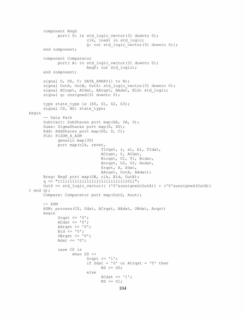
104
component RegS
port( D: in std_logic_vector(31 downto 0);
clk, load: in std_logic;
Q: out std_logic_vector(31 downto 0));
end component;
component Comparator
port( A: in std_logic_vector(31 downto 0);
Aeq0: out std_logic);
end component;
signal D, DS, C: DATA_ARRAY(1 to N);
signal OutA, OutB, OutS: std_logic_vector(31 downto 0);
signal ACrqst, ACdat, AArqst, AAdat, Bld: std_logic;
signal q: unsigned(31 downto 0);
type state_type is (S0, S1, S2, S3);
signal CS, NS: state_type;
begin
-- Data Path
Subtract: SubShares port map(XA, YA, D);
Sums: SigmaShares port map(D, DS);
Add: AddShares port map(DS, D, C);
PiA: PiSDM_A_ASM
generic map(30)
port map(clk, reset,
TIrqst, r, a1, b1, TIdat,
ACrqst, C, ACdat,
Birqst, U1, V1, Bidat,
Borqst, U2, V2, Bodat,
Xrqst, X, Xdat,
AArqst, OutA, AAdat);
Breg: RegS port map(OB, clk, Bld, OutB);
q <= "11111111111111111111111111111011";
OutS <= std_logic_vector(( ('0'&unsigned(OutA)) + ('0'&unsigned(OutB))
) mod q);
Compare: Comparator port map(OutS, Aout);
-- ASM
ASM: process(CS, Sdat, ACrqst, AAdat, OBdat, Arqst)
begin
Srqst <= '0';
ACdat <= '0';
AArqst <= '0';
Bld <= '0';
OBrqst <= '0';
Adat <= '0';
case CS is
when S0 =>
Srqst <= '1';
if Sdat = '0' or ACrqst = '0' then
NS <= S0;
else
ACdat <= '1';
NS <= S1;

105
end if;
when S1 =>
AArqst <= '1';
if AAdat = '0' then
NS <= S1;
else
OBrqst <= '1';
if OBdat = '0' then
NS <= S2;
else
Bld <= '1';
if Arqst = '0' then
NS <= S3;
else
Adat <= '1';
NS <= S0;
end if;
end if;
end if;
when S2 =>
if OBdat = '0' then
NS <= S2;
else
Bld <= '1';
if Arqst = '0' then
NS <= S3;
else
Adat <= '1';
NS <= S0;
end if;
end if;
when S3 =>
if Arqst = '0' then
NS <= S3;
else
Adat <= '1';
NS <= S0;
end if;
end case;
end process;
-- DFF
sync: process
begin
wait until clk'event and clk = '1';
if reset = '1' then
CS <= S0;
else
CS <= NS;
end if;
end process;
end;
SDM_B.vhd, PiSDM_B.vhd, SC_B.vhd:

106
library ieee;
use ieee.std_logic_1164.all;
use ieee.std_logic_unsigned.all;
use ieee.numeric_std.all;
entity SDM_B is
port (a2, b2, I, uB, vB: in std_logic_vector(31 downto 0); -- TI input
and additive shares
U1, V1: in std_logic_vector(31 downto 0); -- Step 1 input
from A
U2, V2: out std_logic_vector(31 downto 0); -- Step 2 output
to A
X: in std_logic_vector(31 downto 0); -- Step 3 input from A
Bout: out std_logic_vector(31 downto 0));
end;
architecture behavioral of SDM_B is
signal q: unsigned(31 downto 0);
signal Y1, Y2: std_logic_vector(31 downto 0);
begin
q <= "11111111111111111111111111111011";
U2 <= std_logic_vector((('0'&unsigned(uB)) + ('0'&(q - unsigned(a2))))
mod q);
V2 <= std_logic_vector((('0'&unsigned(vB)) + ('0'&(q - unsigned(b2))))
mod q);
Bout <= std_logic_vector((("000"&(unsigned((U1*vB)) mod q)) +
("000"&(unsigned(V1*uB) mod q)) + ("000"&unsigned(X)) +
("000"&(unsigned((uB*vB)) mod q)) + ("000"&unsigned(I))) mod q);
end behavioral;
library ieee;
use ieee.std_logic_1164.all;
entity SDM_B_ASM is
port( clk, reset: in std_logic;
TIrqst: out std_logic; -- TI request: randomness
I, a2, b2: in std_logic_vector(31 downto 0); -- randomness
TIdat: in std_logic; -- TI data valid
Srqst: out std_logic; -- Shares request
uB, vB: in std_logic_vector(31 downto 0); -- Shares
Sdat: in std_logic; -- Shares valid
Aorqst: out std_logic; -- Step1 data request to A
U1, V1: in std_logic_vector(31 downto 0); -- Step1 input
from A
Aodat: in std_logic; -- Step1 data valid from A
Airqst: in std_logic; -- Step2 data request from A
U2, V2: out std_logic_vector(31 downto 0); -- Step2 output
to A
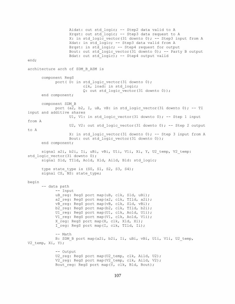
107
Aidat: out std_logic; -- Step2 data valid to A
Xrqst: out std_logic; -- Step3 data request to A
X: in std_logic_vector(31 downto 0); -- Step3 input from A
Xdat: in std_logic; -- Step3 data valid from A
Brqst: in std_logic; -- Step4 request for output
Bout: out std_logic_vector(31 downto 0); -- Party B output
Bdat: out std_logic); -- Step4 output valid
end;
architecture arch of SDM_B_ASM is
component RegS
port( D: in std_logic_vector(31 downto 0);
clk, load: in std_logic;
Q: out std_logic_vector(31 downto 0));
end component;
component SDM_B
port (a2, b2, I, uB, vB: in std_logic_vector(31 downto 0); -- TI
input and additive shares
U1, V1: in std_logic_vector(31 downto 0); -- Step 1 input
from A
U2, V2: out std_logic_vector(31 downto 0); -- Step 2 output
to A
X: in std_logic_vector(31 downto 0); -- Step 3 input from A
Bout: out std_logic_vector(31 downto 0));
end component;
signal a2i, b2i, Ii, uBi, vBi, U1i, V1i, Xi, Y, U2_temp, V2_temp:
std_logic_vector(31 downto 0);
signal Sld, TIld, Aold, Xld, Aild, Bld: std_logic;
type state_type is (S0, S1, S2, S3, S4);
signal CS, NS: state_type;
begin
-- data path
-- Input
uB_reg: RegS port map(uB, clk, Sld, uBi);
a2_reg: RegS port map(a2, clk, TIld, a2i);
vB_reg: RegS port map(vB, clk, Sld, vBi);
b2_reg: RegS port map(b2, clk, TIld, b2i);
U1_reg: RegS port map(U1, clk, Aold, U1i);
V1_reg: RegS port map(V1, clk, Aold, V1i);
X_reg: RegS port map(X, clk, Xld, Xi);
I_reg: RegS port map(I, clk, TIld, Ii);
-- Math
B: SDM_B port map(a2i, b2i, Ii, uBi, vBi, U1i, V1i, U2_temp,
V2_temp, Xi, Y);
-- Output
U2_reg: RegS port map(U2_temp, clk, Aild, U2);
V2_reg: RegS port map(V2_temp, clk, Aild, V2);
Bout_reg: RegS port map(Y, clk, Bld, Bout);

108
-- ASM
ASM: process(CS, Sdat, TIdat, Aodat, Airqst, Xdat, Brqst)
begin
Srqst <= '0';
TIrqst <= '0';
Aorqst <= '0';
Sld <= '0';
TIld <= '0';
Aild <= '0';
Aold <= '0';
Aidat <= '0';
Xrqst <= '0';
Xld <= '0';
Bld <= '0';
Bdat <= '0';
case CS is
when S0 =>
Srqst <= '1';
TIrqst <= '1';
Aorqst <= '1';
if Sdat = '0' or TIdat = '0' then
NS <= S0;
else
Sld <= '1';
TIld <= '1';
Aild <= '1';
if Aodat = '0' then
NS <= S1;
else
Aold <= '1';
if Airqst = '0' then
NS <= S2;
else
Aidat <= '1';
Xrqst <= '1';
if Xdat = '0' then
NS <= S3;
else
Xld <= '1';
Bld <= '1';
if Brqst = '0' then
NS <= S4;
else
Bdat <='1';
NS <= S0;
end if;
end if;
end if;
end if;
end if;
when S1 =>
if Aodat = '0' then
NS <= S1;
else
Aold <= '1';

109
if Airqst = '0' then
NS <= S2;
else
Aidat <= '1';
Xrqst <= '1';
if Xdat = '0' then
NS <= S3;
else
Xld <= '1';
Bld <= '1';
if Brqst = '0' then
NS <= S4;
else
Bdat <='1';
NS <= S0;
end if;
end if;
end if;
end if;
when S2 =>
if Airqst = '0' then
NS <= S2;
else
Aidat <= '1';
Xrqst <= '1';
if Xdat = '0' then
NS <= S3;
else
Xld <= '1';
Bld <= '1';
if Brqst = '0' then
NS <= S4;
else
Bdat <='1';
NS <= S0;
end if;
end if;
end if;
when S3 =>
Xrqst <= '1';
if Xdat = '0' then
NS <= S3;
else
Xld <= '1';
Bld <= '1';
if Brqst = '0' then
NS <= S4;
else
Bdat <='1';
NS <= S0;
end if;
end if;
when S4 =>
if Brqst = '0' then
NS <= S4;
else

110
Bdat <='1';
NS <= S0;
end if;
end case;
end process;
-- DFF
sync: process
begin
wait until clk'event and clk = '1';
if reset = '1' then
CS <= S0;
else
CS <= NS;
end if;
end process;
end;
-- Pi Product SDM Party B ASM
library ieee;
use ieee.std_logic_1164.all;
use ieee.std_logic_unsigned.all;
use ieee.numeric_std.all;
use work.MY_PACKAGE.all;
entity PiSDM_B_ASM is
generic(N: natural := 32);
port( clk, reset: in std_logic;
TIrqst: out std_logic; -- TI request: randomness
I, a2, b2: in std_logic_vector(31 downto 0); -- randomness
TIdat: in std_logic; -- TI data valid
Crqst: out std_logic; -- Shares request
C: in DATA_ARRAY(1 to N); -- Shares
Cdat: in std_logic; -- Shares valid
Aorqst: out std_logic; -- Step1 data request to A
U1, V1: in std_logic_vector(31 downto 0); -- Step1 input
from A
Aodat: in std_logic; -- Step1 data valid from A
Airqst: in std_logic; -- Step2 data request from A
U2, V2: out std_logic_vector(31 downto 0); -- Step2 output
to A
Aidat: out std_logic; -- Step2 data valid to A
Xrqst: out std_logic; -- Step3 data request to A
X: in std_logic_vector(31 downto 0); -- Step3 input from A
Xdat: in std_logic; -- Step3 data valid from A
Brqst: in std_logic; -- Step4 request for output
Bout: out std_logic_vector(31 downto 0); -- Party B output
Bdat: out std_logic); -- Step4 output valid
end;
architecture arch of PiSDM_B_ASM is
component SDM_B_ASM
port( clk, reset: in std_logic;
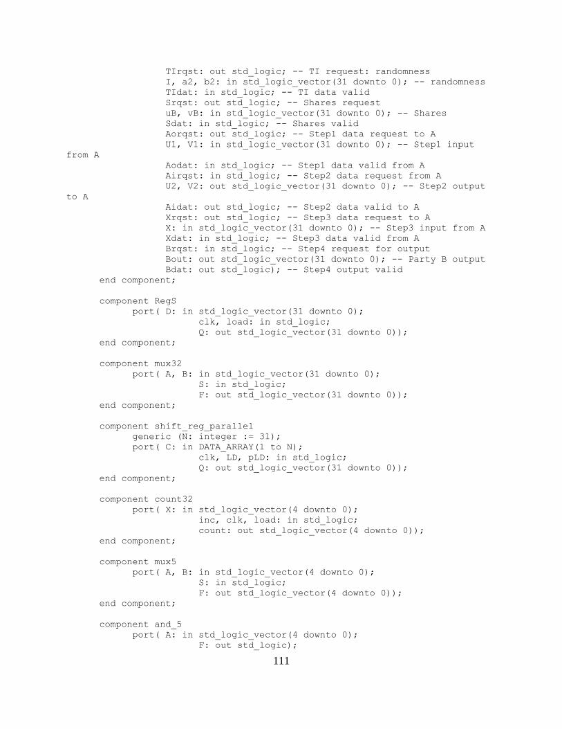
111
TIrqst: out std_logic; -- TI request: randomness
I, a2, b2: in std_logic_vector(31 downto 0); -- randomness
TIdat: in std_logic; -- TI data valid
Srqst: out std_logic; -- Shares request
uB, vB: in std_logic_vector(31 downto 0); -- Shares
Sdat: in std_logic; -- Shares valid
Aorqst: out std_logic; -- Step1 data request to A
U1, V1: in std_logic_vector(31 downto 0); -- Step1 input
from A
Aodat: in std_logic; -- Step1 data valid from A
Airqst: in std_logic; -- Step2 data request from A
U2, V2: out std_logic_vector(31 downto 0); -- Step2 output
to A
Aidat: out std_logic; -- Step2 data valid to A
Xrqst: out std_logic; -- Step3 data request to A
X: in std_logic_vector(31 downto 0); -- Step3 input from A
Xdat: in std_logic; -- Step3 data valid from A
Brqst: in std_logic; -- Step4 request for output
Bout: out std_logic_vector(31 downto 0); -- Party B output
Bdat: out std_logic); -- Step4 output valid
end component;
component RegS
port( D: in std_logic_vector(31 downto 0);
clk, load: in std_logic;
Q: out std_logic_vector(31 downto 0));
end component;
component mux32
port( A, B: in std_logic_vector(31 downto 0);
S: in std_logic;
F: out std_logic_vector(31 downto 0));
end component;
component shift_reg_parallel
generic (N: integer := 31);
port( C: in DATA_ARRAY(1 to N);
clk, LD, pLD: in std_logic;
Q: out std_logic_vector(31 downto 0));
end component;
component count32
port( X: in std_logic_vector(4 downto 0);
inc, clk, load: in std_logic;
count: out std_logic_vector(4 downto 0));
end component;
component mux5
port( A, B: in std_logic_vector(4 downto 0);
S: in std_logic;
F: out std_logic_vector(4 downto 0));
end component;
component and_5
port( A: in std_logic_vector(4 downto 0);
F: out std_logic);
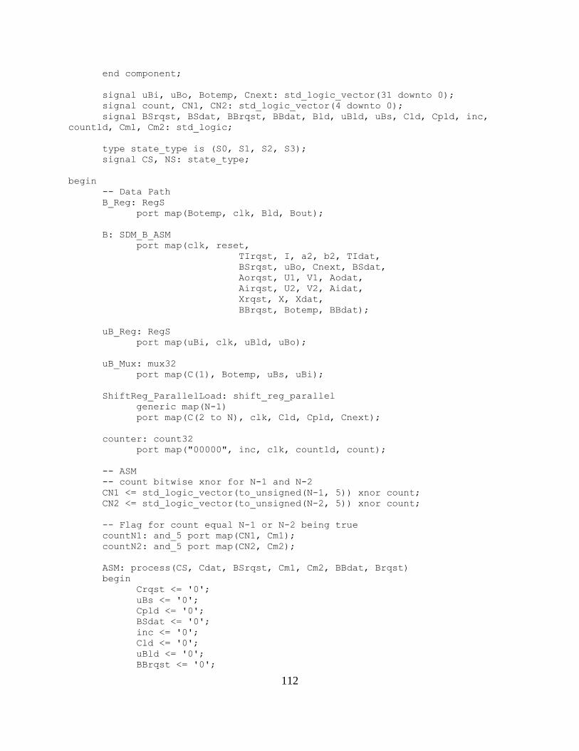
112
end component;
signal uBi, uBo, Botemp, Cnext: std_logic_vector(31 downto 0);
signal count, CN1, CN2: std_logic_vector(4 downto 0);
signal BSrqst, BSdat, BBrqst, BBdat, Bld, uBld, uBs, Cld, Cpld, inc,
countld, Cm1, Cm2: std_logic;
type state_type is (S0, S1, S2, S3);
signal CS, NS: state_type;
begin
-- Data Path
B_Reg: RegS
port map(Botemp, clk, Bld, Bout);
B: SDM_B_ASM
port map(clk, reset,
TIrqst, I, a2, b2, TIdat,
BSrqst, uBo, Cnext, BSdat,
Aorqst, U1, V1, Aodat,
Airqst, U2, V2, Aidat,
Xrqst, X, Xdat,
BBrqst, Botemp, BBdat);
uB_Reg: RegS
port map(uBi, clk, uBld, uBo);
uB_Mux: mux32
port map(C(1), Botemp, uBs, uBi);
ShiftReg_ParallelLoad: shift_reg_parallel
generic map(N-1)
port map(C(2 to N), clk, Cld, Cpld, Cnext);
counter: count32
port map("00000", inc, clk, countld, count);
-- ASM
-- count bitwise xnor for N-1 and N-2
CN1 <= std_logic_vector(to_unsigned(N-1, 5)) xnor count;
CN2 <= std_logic_vector(to_unsigned(N-2, 5)) xnor count;
-- Flag for count equal N-1 or N-2 being true
countN1: and_5 port map(CN1, Cm1);
countN2: and_5 port map(CN2, Cm2);
ASM: process(CS, Cdat, BSrqst, Cm1, Cm2, BBdat, Brqst)
begin
Crqst <= '0';
uBs <= '0';
Cpld <= '0';
BSdat <= '0';
inc <= '0';
Cld <= '0';
uBld <= '0';
BBrqst <= '0';

113
BSdat <= '0';
Bdat <= '0';
countld <= '0';
Bld <= '0';
case CS is
when S0 =>
Crqst <= '1';
uBs <= '1';
Cpld <= '1';
if Cdat = '0' then
NS <= S0;
else
Cld <= '1';
countld <= '1';
if BSrqst = '0' then
NS <= S2;
else
BSdat <= '1';
uBld <= '1';
NS <= S1;
end if;
end if;
when S1 =>
if Cm1 = '0' then
BBrqst <= '1';
bSdat <= '1';
if BBdat = '0' then
NS <= S1;
else
inc <= '1';
if Cm2 = '0' then
Cld <= '1';
uBld <= '1';
if BSrqst = '0' then
NS <= S3;
else
BSdat <= '1';
NS <= S1;
end if;
else
if Brqst = '0' then
NS <= S1;
else
Bld <= '1';
Bdat <= '1';
NS <= S0;
end if;
end if;
end if;
else
if Brqst = '0' then
NS <= S1;
else
Bld <= '1';
Bdat <= '1';

114
NS <= S0;
end if;
end if;
when S2 =>
if BSrqst = '0' then
NS <= S2;
else
uBld <= '1';
BSdat <= '1';
NS <= S1;
end if;
when S3 =>
if Cm1 = '0' then
if BSrqst = '0' then
NS <= S3;
else
BSdat <= '1';
NS <= S1;
end if;
else
if Brqst = '0' then
NS <= S1;
else
Bld <= '1';
Bdat <= '1';
NS <= S0;
end if;
end if;
end case;
end process;
-- DFF
sync: process
begin
wait until clk'event and clk = '1';
if reset = '1' then
CS <= S0;
else
CS <= NS;
end if;
end process;
end;
-- SC SDM Party B ASM
library ieee;
use ieee.std_logic_1164.all;
use work.MY_PACKAGE.all;
entity SC_B_ASM is
generic(N: natural := 30);
port( clk, reset: in std_logic;
TIrqst: out std_logic; -- TI request: randomness
I, a2, b2: in std_logic_vector(31 downto 0); -- randomness
TIdat: in std_logic; -- TI data valid
Srqst: out std_logic; -- Shares request

115
XB, YB: in DATA_ARRAY(1 to N); -- Shares
Sdat: in std_logic; -- Shares valid
Aorqst: out std_logic; -- Step1 data request to A
U1, V1: in std_logic_vector(31 downto 0); -- Step1 input
from A
Aodat: in std_logic; -- Step1 data valid from A
Airqst: in std_logic; -- Step2 data request from A
U2, V2: out std_logic_vector(31 downto 0); -- Step2 output
to A
Aidat: out std_logic; -- Step2 data valid to A
Xrqst: out std_logic; -- Step3 data request to A
X: in std_logic_vector(31 downto 0); -- Step3 input from A
Xdat: in std_logic; -- Step3 data valid from A
Brqst: in std_logic; -- Step4 request for output
Bout: out std_logic_vector(31 downto 0); -- Party B output
Bdat: out std_logic); -- Step4 output valid
end;
architecture arch of SC_B_ASM is
component PiSDM_B_ASM
generic(N: natural := 32);
port( clk, reset: in std_logic;
TIrqst: out std_logic; -- TI request: randomness
I, a2, b2: in std_logic_vector(31 downto 0); --
randomness
TIdat: in std_logic; -- TI data valid
Crqst: out std_logic; -- Shares request
C: in DATA_ARRAY(1 to N); -- Shares
Cdat: in std_logic; -- Shares valid
Aorqst: out std_logic; -- Step1 data request to A
U1, V1: in std_logic_vector(31 downto 0); -- Step1
input from A
Aodat: in std_logic; -- Step1 data valid from A
Airqst: in std_logic; -- Step2 data request from A
U2, V2: out std_logic_vector(31 downto 0); -- Step2
output to A
Aidat: out std_logic; -- Step2 data valid to A
Xrqst: out std_logic; -- Step3 data request to A
X: in std_logic_vector(31 downto 0); -- Step3 input
from A
Xdat: in std_logic; -- Step3 data valid from A
Brqst: in std_logic; -- Step4 request for output
Bout: out std_logic_vector(31 downto 0); -- Party B
output
Bdat: out std_logic); -- Step4 output valid
end component;
component SubShares
generic (N: integer := 30);
port( A, B: in DATA_ARRAY(1 to N);
C: out DATA_ARRAY(1 to N));
end component;
component SigmaShares
generic (N: integer := 30);
port( D: in DATA_ARRAY(1 to N);

116
DS: out DATA_ARRAY(1 to N));
end component;
component AddShares1
generic (N: integer := 30);
port( A, B: in DATA_ARRAY(1 to N);
C: out DATA_ARRAY(1 to N));
end component;
component RegS
port( D: in std_logic_vector(31 downto 0);
clk, load: in std_logic;
Q: out std_logic_vector(31 downto 0));
end component;
component Comparator
port( A: in std_logic_vector(31 downto 0);
Aeq0: out std_logic);
end component;
signal D, DS, C: DATA_ARRAY(1 to N);
signal Bo: std_logic_vector(31 downto 0);
signal BCrqst, BCdat, BBrqst, BBdat: std_logic;
type state_type is (S0, S1, S2);
signal CS, NS: state_type;
begin
-- Data Path
Subtract: SubShares port map(XB, YB, D);
Sums: SigmaShares port map(D, DS);
Add: AddShares1 port map(DS, D, C);
PiB: PiSDM_B_ASM
generic map(30)
port map(clk, reset,
TIrqst, I, a2, b2, TIdat,
BCrqst, C, BCdat,
Aorqst, U1, V1, Aodat,
Airqst, U2, V2, Aidat,
Xrqst, X, Xdat,
BBrqst, Bo, BBdat);
Bout <= Bo;
--OutReg: RegS port map(Bo, clk, Bld, Bout);
-- ASM
ASM: process(CS, Sdat, BCrqst, BBdat, Brqst)
begin
Srqst <= '0';
BCdat <= '0';
BBrqst <= '0';
Bdat <= '0';
case CS is
when S0 =>
Srqst <= '1';
if Sdat = '0' or BCrqst = '0' then

117
NS <= S0;
else
BCdat <= '1';
NS <= S1;
end if;
when S1 =>
BBrqst <= '1';
if BBdat = '0' then
NS <= S1;
else
if Brqst = '0' then
NS <= S2;
else
Bdat <= '1';
NS <= S0;
end if;
end if;
when S2 =>
if Brqst = '0' then
NS <= S2;
else
Bdat <= '1';
NS <= S0;
end if;
end case;
end process;
-- DFF
sync: process
begin
wait until clk'event and clk = '1';
if reset = '1' then
CS <= S0;
else
CS <= NS;
end if;
end process;
end;
SDM_chip.vhd:
library ieee;
use ieee.std_logic_1164.all;
use ieee.std_logic_unsigned.all;
entity SDM_chip is
port( clk, reset: in std_logic;
uA, vA, uB, vB: in std_logic_vector(31 downto 0);
Ao, Bo: out std_logic_vector(31 downto 0));
end;
architecture structural of SDM_chip is
component SDM_TI
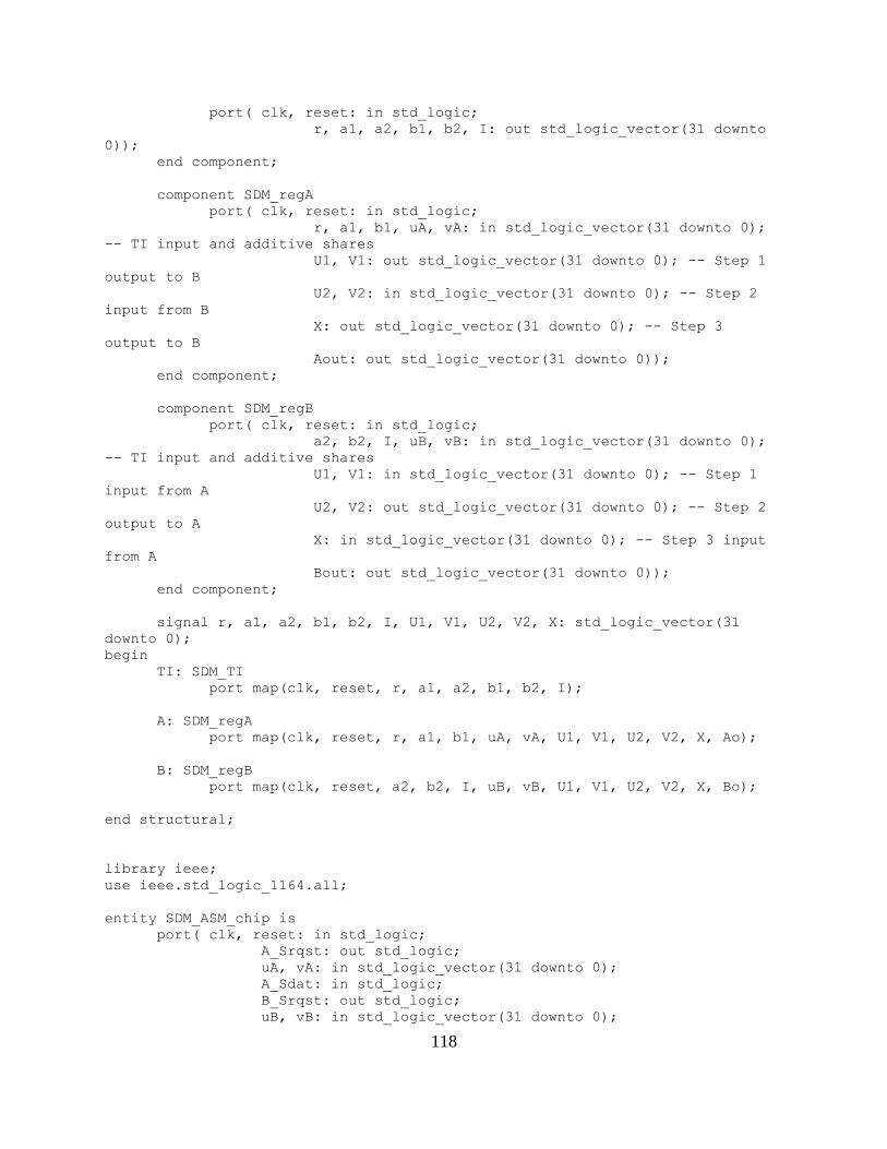
118
port( clk, reset: in std_logic;
r, a1, a2, b1, b2, I: out std_logic_vector(31 downto
0));
end component;
component SDM_regA
port( clk, reset: in std_logic;
r, a1, b1, uA, vA: in std_logic_vector(31 downto 0);
-- TI input and additive shares
U1, V1: out std_logic_vector(31 downto 0); -- Step 1
output to B
U2, V2: in std_logic_vector(31 downto 0); -- Step 2
input from B
X: out std_logic_vector(31 downto 0); -- Step 3
output to B
Aout: out std_logic_vector(31 downto 0));
end component;
component SDM_regB
port( clk, reset: in std_logic;
a2, b2, I, uB, vB: in std_logic_vector(31 downto 0);
-- TI input and additive shares
U1, V1: in std_logic_vector(31 downto 0); -- Step 1
input from A
U2, V2: out std_logic_vector(31 downto 0); -- Step 2
output to A
X: in std_logic_vector(31 downto 0); -- Step 3 input
from A
Bout: out std_logic_vector(31 downto 0));
end component;
signal r, a1, a2, b1, b2, I, U1, V1, U2, V2, X: std_logic_vector(31
downto 0);
begin
TI: SDM_TI
port map(clk, reset, r, a1, a2, b1, b2, I);
A: SDM_regA
port map(clk, reset, r, a1, b1, uA, vA, U1, V1, U2, V2, X, Ao);
B: SDM_regB
port map(clk, reset, a2, b2, I, uB, vB, U1, V1, U2, V2, X, Bo);
end structural;
library ieee;
use ieee.std_logic_1164.all;
entity SDM_ASM_chip is
port( clk, reset: in std_logic;
A_Srqst: out std_logic;
uA, vA: in std_logic_vector(31 downto 0);
A_Sdat: in std_logic;
B_Srqst: out std_logic;
uB, vB: in std_logic_vector(31 downto 0);

119
B_Sdat: in std_logic;
Arqst: in std_logic;
Ao: out std_logic_vector(31 downto 0);
Adat: out std_logic;
Brqst: in std_logic;
Bo: out std_logic_vector(31 downto 0);
Bdat: out std_logic);
end;
architecture structural of SDM_ASM_chip is
component SDM_TI_ASM
port( clk, reset: in std_logic;
Arqst: in std_logic;
r, a1, b1: out std_logic_vector(31 downto 0);
Adat: out std_logic;
Brqst: in std_logic;
I, a2, b2: out std_logic_vector(31 downto 0);
Bdat: out std_logic);
end component;
component SDM_A_ASM
port( clk, reset: in std_logic;
TIrqst: out std_logic; -- TI request: randomness
r, a1, b1: in std_logic_vector(31 downto 0); --
randomness
TIdat: in std_logic; -- TI data valid
Srqst: out std_logic; -- Shares request
uA, vA: in std_logic_vector(31 downto 0); -- Shares
Sdat: in std_logic; -- Shares valid
Birqst: in std_logic; -- Step1 data request from B
U1, V1: out std_logic_vector(31 downto 0); -- Step1
output to B
Bidat: out std_logic; -- Step1 data valid to B
Borqst: out std_logic; -- Step2 data request to B
U2, V2: in std_logic_vector(31 downto 0); -- Step2
input from B
Bodat: in std_logic; -- Step2 data valid from B
Xrqst: in std_logic; -- Step3 data request from B
X: out std_logic_vector(31 downto 0); -- Step3 output
to B
Xdat: out std_logic; -- Step3 data valid to B
Arqst: in std_logic; -- Step4 request for output
Aout: out std_logic_vector(31 downto 0); -- Party A
output
Adat: out std_logic); -- Step4 output valid
end component;
component SDM_B_ASM
port( clk, reset: in std_logic;
TIrqst: out std_logic; -- TI request: randomness
I, a2, b2: in std_logic_vector(31 downto 0); --
randomness
TIdat: in std_logic; -- TI data valid
Srqst: out std_logic; -- Shares request
uB, vB: in std_logic_vector(31 downto 0); -- Shares
Sdat: in std_logic; -- Shares valid

120
Aorqst: out std_logic; -- Step1 data request to A
U1, V1: in std_logic_vector(31 downto 0); -- Step1
input from A
Aodat: in std_logic; -- Step1 data valid from A
Airqst: in std_logic; -- Step2 data request from A
U2, V2: out std_logic_vector(31 downto 0); -- Step2
output to A
Aidat: out std_logic; -- Step2 data valid to A
Xrqst: out std_logic; -- Step3 data request to A
X: in std_logic_vector(31 downto 0); -- Step3 input
from A
Xdat: in std_logic; -- Step3 data valid from A
Brqst: in std_logic; -- Step4 request for output
Bout: out std_logic_vector(31 downto 0); -- Party B
output
Bdat: out std_logic); -- Step4 output valid
end component;
signal TI_Arqst, TI_Adat, TI_Brqst, TI_Bdat: std_logic; -- TI OCDDC
signal Step1rqst, Step1dat, Step2rqst, Step2dat, Xrqst, Xdat:
std_logic; -- A&B OCDDC
signal r, a1, a2, b1, b2, I, U1, V1, U2, V2, X: std_logic_vector(31
downto 0);
begin
TI: SDM_TI_ASM
port map(clk, reset,
TI_Arqst, r, a1, b1, TI_Adat,
TI_Brqst, I, a2, b2, TI_Bdat);
A: SDM_A_ASM
port map(clk, reset,
TI_Arqst, r, a1, b1, TI_Adat,
A_Srqst, uA, vA, A_Sdat,
Step1rqst, U1, V1, Step1dat,
Step2rqst, U2, V2, Step2dat,
Xrqst, X, Xdat,
Arqst, Ao, Adat);
B: SDM_B_ASM
port map(clk, reset,
TI_Brqst, I, a2, b2, TI_Bdat,
B_Srqst, uB, vB, B_Sdat,
Step1rqst, U1, V1, Step1dat,
Step2rqst, U2, V2, Step2dat,
Xrqst, X, Xdat,
Brqst, Bo, Bdat);
end structural;
TB_SDM.vhd:
library ieee;

121
use ieee.std_logic_1164.all;
use ieee.std_logic_unsigned.all;
use ieee.numeric_std.all;
entity tb_SDM is
port(correct: out std_logic);
end;
architecture tb of tb_SDM is
component SDM_chip
port( clk, reset: std_logic;
uA, vA, uB, vB: in std_logic_vector(31 downto 0);
Ao, Bo: out std_logic_vector(31 downto 0));
end component;
component SDM_ASM_chip is
port( clk, reset: in std_logic;
A_Srqst: out std_logic;
uA, vA: in std_logic_vector(31 downto 0);
A_Sdat: in std_logic;
B_Srqst: out std_logic;
uB, vB: in std_logic_vector(31 downto 0);
B_Sdat: in std_logic;
Arqst: in std_logic;
Ao: out std_logic_vector(31 downto 0);
Adat: out std_logic;
Brqst: in std_logic;
Bo: out std_logic_vector(31 downto 0);
Bdat: out std_logic);
end component;
signal q, mult1, mult2: unsigned(31 downto 0);
signal mult2s: unsigned(32 downto 0);
signal uA, vA, uB, vB, Ao, Bo: std_logic_vector(31 downto 0);
signal clk, reset, A_Srqst, A_Sdat, B_Srqst, B_Sdat, Arqst, Adat,
Brqst, Bdat: std_logic;
begin
q <= "11111111111111111111111111111011"; -- 4294967291
mult1 <= unsigned((uA + uB) * (vA + vB)) mod q;
mult2s <= unsigned(('0' & Bo) + ('0' & Ao));
mult2 <= mult2s mod q;
uut: SDM_ASM_chip
port map(clk, reset,
A_Srqst, uA, vA, A_Sdat,
B_Srqst, uB, vB, B_Sdat,
Arqst, Ao, Adat,
Brqst, Bo, Bdat);
correctness: process(mult1, mult2)
begin
if (mult1 = mult2) then
correct <= '1';
else
correct <= '0';

122
end if;
end process;
test: process
begin
A_Sdat <= '0';
B_Sdat <= '0';
wait until A_Srqst = '1' and B_Srqst = '1';
uA <= "01110001100111101111100000011101";
uB <= "01101000111110101000110010110101";
vA <= "01010110011111000111011011101111";
vB <= "00111011000111110000011000110001";
A_Sdat <= '1';
B_Sdat <= '1';
Arqst <= '1';
Brqst <= '1';
wait until Adat = '1' and Bdat = '1';
A_Sdat <= '0';
B_Sdat <= '0';
wait until A_Srqst = '1' and B_Srqst = '1';
uA <= "01000000000000000000000000000011";
uB <= "00000000000000000000000000000001";
vA <= "00000000000000000000000000000001";
vB <= "00000000000000000000000000000001";
A_Sdat <= '1';
B_Sdat <= '1';
Arqst <= '1';
Brqst <= '1';
wait until Adat = '1' and Bdat = '1';
A_Sdat <= '0';
B_Sdat <= '0';
wait until A_Srqst = '1' and B_Srqst = '1';
uA <= "00000000000000000000000000000011";
uB <= "00000000000000000000000000000010";
vA <= "00000000000000000000000000000101";
vB <= "00000000000000000000000000001000";
A_Sdat <= '1';
B_Sdat <= '1';
Arqst <= '1';
Brqst <= '1';
wait;
end process;
clock: process
begin
clk <= '0';
wait for 5 ns;
clk <= '1';
wait for 5 ns;
end process;
rst: process
begin

123
reset <= '1';
wait for 10 ns;
reset <= '0';
wait;
end process;
end tb;
PiSDM_chip.vhd:
library ieee;
use ieee.std_logic_1164.all;
use ieee.std_logic_unsigned.all;
entity SDM_chip is
port( clk, reset: in std_logic;
uA, vA, uB, vB: in std_logic_vector(31 downto 0);
Ao, Bo: out std_logic_vector(31 downto 0));
end;
architecture structural of SDM_chip is
component SDM_TI
port( clk, reset: in std_logic;
r, a1, a2, b1, b2, I: out std_logic_vector(31 downto
0));
end component;
component SDM_regA
port( clk, reset: in std_logic;
r, a1, b1, uA, vA: in std_logic_vector(31 downto 0);
-- TI input and additive shares
U1, V1: out std_logic_vector(31 downto 0); -- Step 1
output to B
U2, V2: in std_logic_vector(31 downto 0); -- Step 2
input from B
X: out std_logic_vector(31 downto 0); -- Step 3
output to B
Aout: out std_logic_vector(31 downto 0));
end component;
component SDM_regB
port( clk, reset: in std_logic;
a2, b2, I, uB, vB: in std_logic_vector(31 downto 0);
-- TI input and additive shares
U1, V1: in std_logic_vector(31 downto 0); -- Step 1
input from A
U2, V2: out std_logic_vector(31 downto 0); -- Step 2
output to A
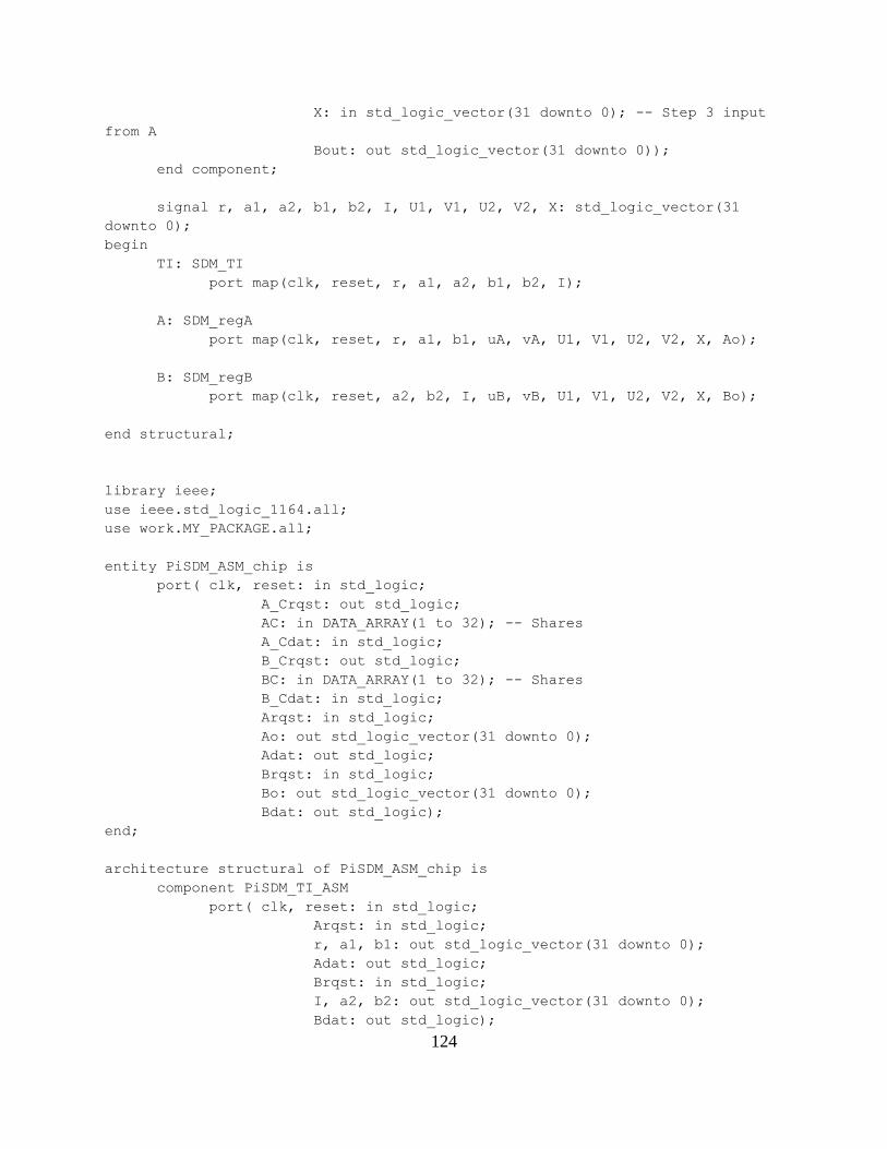
124
X: in std_logic_vector(31 downto 0); -- Step 3 input
from A
Bout: out std_logic_vector(31 downto 0));
end component;
signal r, a1, a2, b1, b2, I, U1, V1, U2, V2, X: std_logic_vector(31
downto 0);
begin
TI: SDM_TI
port map(clk, reset, r, a1, a2, b1, b2, I);
A: SDM_regA
port map(clk, reset, r, a1, b1, uA, vA, U1, V1, U2, V2, X, Ao);
B: SDM_regB
port map(clk, reset, a2, b2, I, uB, vB, U1, V1, U2, V2, X, Bo);
end structural;
library ieee;
use ieee.std_logic_1164.all;
use work.MY_PACKAGE.all;
entity PiSDM_ASM_chip is
port( clk, reset: in std_logic;
A_Crqst: out std_logic;
AC: in DATA_ARRAY(1 to 32); -- Shares
A_Cdat: in std_logic;
B_Crqst: out std_logic;
BC: in DATA_ARRAY(1 to 32); -- Shares
B_Cdat: in std_logic;
Arqst: in std_logic;
Ao: out std_logic_vector(31 downto 0);
Adat: out std_logic;
Brqst: in std_logic;
Bo: out std_logic_vector(31 downto 0);
Bdat: out std_logic);
end;
architecture structural of PiSDM_ASM_chip is
component PiSDM_TI_ASM
port( clk, reset: in std_logic;
Arqst: in std_logic;
r, a1, b1: out std_logic_vector(31 downto 0);
Adat: out std_logic;
Brqst: in std_logic;
I, a2, b2: out std_logic_vector(31 downto 0);
Bdat: out std_logic);

125
end component;
component PiSDM_A_ASM
port( clk, reset: in std_logic;
TIrqst: out std_logic; -- TI request: randomness
r, a1, b1: in std_logic_vector(31 downto 0); --
randomness
TIdat: in std_logic; -- TI data valid
Crqst: out std_logic; -- Shares request
C: in DATA_ARRAY(1 to 32); -- Shares
Cdat: in std_logic; -- Shares valid
Birqst: in std_logic; -- Step1 data request from B
U1, V1: out std_logic_vector(31 downto 0); -- Step1
output to B
Bidat: out std_logic; -- Step1 data valid to B
Borqst: out std_logic; -- Step2 data request to B
U2, V2: in std_logic_vector(31 downto 0); -- Step2
input from B
Bodat: in std_logic; -- Step2 data valid from B
Xrqst: in std_logic; -- Step3 data request from B
X: out std_logic_vector(31 downto 0); -- Step3 output
to B
Xdat: out std_logic; -- Step3 data valid to B
Arqst: in std_logic; -- Step4 request for output
Aout: out std_logic_vector(31 downto 0); -- Party A
output
Adat: out std_logic); -- Step4 output valid
end component;
component PiSDM_B_ASM
port( clk, reset: in std_logic;
TIrqst: out std_logic; -- TI request: randomness
I, a2, b2: in std_logic_vector(31 downto 0); --
randomness
TIdat: in std_logic; -- TI data valid
Crqst: out std_logic; -- Shares request
C: in DATA_ARRAY(1 to 32); -- Shares
Cdat: in std_logic; -- Shares valid
Aorqst: out std_logic; -- Step1 data request to A
U1, V1: in std_logic_vector(31 downto 0); -- Step1
input from A
Aodat: in std_logic; -- Step1 data valid from A
Airqst: in std_logic; -- Step2 data request from A
U2, V2: out std_logic_vector(31 downto 0); -- Step2
output to A
Aidat: out std_logic; -- Step2 data valid to A
Xrqst: out std_logic; -- Step3 data request to A
X: in std_logic_vector(31 downto 0); -- Step3 input
from A

126
Xdat: in std_logic; -- Step3 data valid from A
Brqst: in std_logic; -- Step4 request for output
Bout: out std_logic_vector(31 downto 0); -- Party B
output
Bdat: out std_logic); -- Step4 output valid
end component;
signal TI_Arqst, TI_Adat, TI_Brqst, TI_Bdat: std_logic; -- TI OCDDC
signal Step1rqst, Step1dat, Step2rqst, Step2dat, Xrqst, Xdat:
std_logic; -- A&B OCDDC
signal r, a1, a2, b1, b2, I, U1, V1, U2, V2, X: std_logic_vector(31
downto 0);
begin
TI: PiSDM_TI_ASM
port map(clk, reset,
TI_Arqst, r, a1, b1, TI_Adat,
TI_Brqst, I, a2, b2, TI_Bdat);
A: PiSDM_A_ASM
port map(clk, reset,
TI_Arqst, r, a1, b1, TI_Adat,
A_Crqst, AC, A_Cdat,
Step1rqst, U1, V1, Step1dat,
Step2rqst, U2, V2, Step2dat,
Xrqst, X, Xdat,
Arqst, Ao, Adat);
B: PiSDM_B_ASM
port map(clk, reset,
TI_Brqst, I, a2, b2, TI_Bdat,
B_Crqst, BC, B_Cdat,
Step1rqst, U1, V1, Step1dat,
Step2rqst, U2, V2, Step2dat,
Xrqst, X, Xdat,
Brqst, Bo, Bdat);
end structural;
TB_PiSDM.vhd:
library ieee;
use ieee.std_logic_1164.all;
use ieee.std_logic_unsigned.all;
use ieee.numeric_std.all;
use work.MY_PACKAGE.all;
entity tb_PiSDM is

127
end;
architecture tb of tb_PiSDM is
component PiSDM_ASM_chip is
port( clk, reset: in std_logic;
A_Crqst: out std_logic;
AC: in DATA_ARRAY(1 to 32);
A_Cdat: in std_logic;
B_Crqst: out std_logic;
BC: in DATA_ARRAY(1 to 32);
B_Cdat: in std_logic;
Arqst: in std_logic;
Ao: out std_logic_vector(31 downto 0);
Adat: out std_logic;
Brqst: in std_logic;
Bo: out std_logic_vector(31 downto 0);
Bdat: out std_logic);
end component;
signal AC, BC: DATA_ARRAY(1 to 32);
signal q, expected, calculated: unsigned(31 downto 0);
signal mult2s: unsigned(32 downto 0);
signal uA, vA, uB, vB, Ao, Bo: std_logic_vector(31 downto 0);
signal clk, reset, A_Crqst, A_Cdat, B_Crqst, B_Cdat, Arqst, Adat,
Brqst, Bdat, correct: std_logic;
begin
q <= "11111111111111111111111111111011"; -- 4294967291
-- compute expected result
expected_result: process(AC, BC)
variable iteration_result: DATA_ARRAY(0 to 32);
begin
iteration_result(0) := (0 => '1', others => '0');
-- compute result
for_loop: for I in 1 to 32 loop
iteration_result(I) :=
std_logic_vector((unsigned(iteration_result(I-1)) * ((unsigned(('0' & AC(I))
+ ('0' & BC(I)))) mod q)) mod q);
end loop;
expected <= unsigned(iteration_result(32));
end process;
-- compute calculated result
mult2s <= unsigned(('0' & Bo) + ('0' & Ao));
calculated <= mult2s mod q;
-- correctness signal
correctness: process(expected, calculated)
begin
if (expected = calculated) then
correct <= '1';
else
correct <= '0';

128
end if;
end process;
uut: PiSDM_ASM_chip
port map(clk, reset,
A_Crqst, AC, A_Cdat,
B_Crqst, BC, B_Cdat,
Arqst, Ao, Adat,
Brqst, Bo, Bdat);
test: process
begin
A_Cdat <= '0';
B_Cdat <= '0';
wait until A_Crqst = '1' and B_Crqst = '1';
AC <= ( "00000000000000000000000000000001",
"00000000000000000000000000000001", "00000000000000000000000000000001",
"00000000000000000000000000000001",
"00000000000000000000000000000001",
"00000000000000000000000000000001", "00000000000000000000000000000001",
"00000000000000000000000000000001",
"00000000000000000000000000000001",
"00000000000000000000000000000001", "00000000000000000000000000000001",
"00000000000000000000000000000001",
"00000000000000000000000000000001",
"00000000000000000000000000000001", "00000000000000000000000000000001",
"00000000000000000000000000000001",
"00000000000000000000000000000001",
"00000000000000000000000000000001", "00000000000000000000000000000001",
"00000000000000000000000000000001",
"00000000000000000000000000000001",
"00000000000000000000000000000001", "00000000000000000000000000000001",
"00000000000000000000000000000001",
"00000000000000000000000000000001",
"00000000000000000000000000000001", "00000000000000000000000000000001",
"00000000000000000000000000000001",
"00000000000000000000000000000001",
"00000000000000000000000000000001", "00000000000000000000000000000001",
"00000000000000000000000000000001");
BC <= ( "00000000000000000000000000000000",
"00000000000000000000000000000001", "00000000000000000000000000000001",
"00000000000000000000000000000001",
"00000000000000000000000000000001",
"00000000000000000000000000000001", "00000000000000000000000000000001",
"00000000000000000000000000000001",
"00000000000000000000000000000001",
"00000000000000000000000000000001", "00000000000000000000000000000001",
"00000000000000000000000000000001",
"00000000000000000000000000000001",
"00000000000000000000000000000001", "00000000000000000000000000000001",
"00000000000000000000000000000001",
"00000000000000000000000000000001",
"00000000000000000000000000000001", "00000000000000000000000000000001",
"00000000000000000000000000000001",

129
"00000000000000000000000000000001",
"00000000000000000000000000000001", "00000000000000000000000000000001",
"00000000000000000000000000000001",
"00000000000000000000000000000001",
"00000000000000000000000000000001", "00000000000000000000000000000001",
"00000000000000000000000000000001",
"00000000000000000000000000000001",
"00000000000000000000000000000001", "00000000000000000000000000000001",
"00000000000000000000000000000001");
A_Cdat <= '1';
B_Cdat <= '1';
Arqst <= '1';
Brqst <= '1';
wait until Adat = '1' and Bdat = '1';
wait for 10 ns;
A_Cdat <= '0';
B_Cdat <= '0';
Arqst <= '0';
Brqst <= '0';
wait;
end process;
clock: process
begin
clk <= '0';
wait for 5 ns;
clk <= '1';
wait for 5 ns;
end process;
rst: process
begin
reset <= '1';
wait for 10 ns;
reset <= '0';
wait;
end process;
end tb;
SC_chip.vhd:
-- Secure Comparison ASM Chip
library ieee;
use ieee.std_logic_1164.all;
use work.MY_PACKAGE.all;
entity SC_ASM_chip is
port( clk, reset: in std_logic;
A_Srqst: out std_logic;
XA, YA: in DATA_ARRAY(1 to 30); -- Shares

130
A_Sdat: in std_logic;
B_Srqst: out std_logic;
XB, YB: in DATA_ARRAY(1 to 30); -- Shares
B_Sdat: in std_logic;
Arqst: in std_logic;
Ao: out std_logic;
Adat: out std_logic);
end;
architecture structural of SC_ASM_chip is
component SC_TI_ASM
port( clk, reset: in std_logic;
Arqst: in std_logic;
r, a1, b1: out std_logic_vector(31 downto 0);
Adat: out std_logic;
Brqst: in std_logic;
I, a2, b2: out std_logic_vector(31 downto 0);
Bdat: out std_logic);
end component;
component SC_A_ASM
generic(N: natural := 30);
port( clk, reset: in std_logic;
TIrqst: out std_logic; -- TI request: randomness
r, a1, b1: in std_logic_vector(31 downto 0); --
randomness
TIdat: in std_logic; -- TI data valid
Srqst: out std_logic; -- Shares request
XA, YA: in DATA_ARRAY(1 to N); -- Shares
Sdat: in std_logic; -- Shares valid
Birqst: in std_logic; -- Step1 data request from B
U1, V1: out std_logic_vector(31 downto 0); -- Step1
output to B
Bidat: out std_logic; -- Step1 data valid to B
Borqst: out std_logic; -- Step2 data request to B
U2, V2: in std_logic_vector(31 downto 0); -- Step2
input from B
Bodat: in std_logic; -- Step2 data valid from B
Xrqst: in std_logic; -- Step3 data request from B
X: out std_logic_vector(31 downto 0); -- Step3 output
to B
Xdat: out std_logic; -- Step3 data valid to B
OBrqst: out std_logic; -- Step4 OutB data request
from B
OB: in std_logic_vector(31 downto 0);
OBdat: in std_logic; -- Step4 OutB data request from
B
Arqst: in std_logic; -- Step4 request for output
Aout: out std_logic; -- Party A output

131
Adat: out std_logic); -- Step4 output valid
end component;
component SC_B_ASM
generic(N: natural := 30);
port( clk, reset: in std_logic;
TIrqst: out std_logic; -- TI request: randomness
I, a2, b2: in std_logic_vector(31 downto 0); --
randomness
TIdat: in std_logic; -- TI data valid
Srqst: out std_logic; -- Shares request
XB, YB: in DATA_ARRAY(1 to N); -- Shares
Sdat: in std_logic; -- Shares valid
Aorqst: out std_logic; -- Step1 data request to A
U1, V1: in std_logic_vector(31 downto 0); -- Step1
input from A
Aodat: in std_logic; -- Step1 data valid from A
Airqst: in std_logic; -- Step2 data request from A
U2, V2: out std_logic_vector(31 downto 0); -- Step2
output to A
Aidat: out std_logic; -- Step2 data valid to A
Xrqst: out std_logic; -- Step3 data request to A
X: in std_logic_vector(31 downto 0); -- Step3 input
from A
Xdat: in std_logic; -- Step3 data valid from A
Brqst: in std_logic; -- Step4 request for output
Bout: out std_logic_vector(31 downto 0); -- Party B
output
Bdat: out std_logic); -- Step4 output valid
end component;
signal TI_Arqst, TI_Adat, TI_Brqst, TI_Bdat: std_logic; -- TI OCDDC
signal Step1rqst, Step1dat, Step2rqst, Step2dat, Xrqst, Xdat, OBrqst,
OBdat: std_logic; -- A&B OCDDC
signal r, a1, a2, b1, b2, I, U1, V1, U2, V2, X, OB: std_logic_vector(31
downto 0);
begin
TI: SC_TI_ASM
port map(clk, reset,
TI_Arqst, r, a1, b1, TI_Adat,
TI_Brqst, I, a2, b2, TI_Bdat);
A: SC_A_ASM
port map(clk, reset,
TI_Arqst, r, a1, b1, TI_Adat,
A_Srqst, XA, YA, A_Sdat,
Step1rqst, U1, V1, Step1dat,
Step2rqst, U2, V2, Step2dat,

132
Xrqst, X, Xdat,
OBrqst, OB, OBdat,
Arqst, Ao, Adat);
B: SC_B_ASM
port map(clk, reset,
TI_Brqst, I, a2, b2, TI_Bdat,
B_Srqst, XB, YB, B_Sdat,
Step1rqst, U1, V1, Step1dat,
Step2rqst, U2, V2, Step2dat,
Xrqst, X, Xdat,
OBrqst, OB, OBdat);
end structural;
TB_SC.vhd:
library ieee;
use ieee.std_logic_1164.all;
use ieee.std_logic_unsigned.all;
use ieee.numeric_std.all;
use work.MY_PACKAGE.all;
use work.tb_Xshares.all;
use work.tb_Yshares.all;
entity tb_SC is
end;
architecture tb of tb_SC is
component SC_ASM_chip is
port( clk, reset: in std_logic;
A_Srqst: out std_logic;
XA, YA: in DATA_ARRAY(1 to 30); -- Shares
A_Sdat: in std_logic;
B_Srqst: out std_logic;
XB, YB: in DATA_ARRAY(1 to 30); -- Shares
B_Sdat: in std_logic;
Arqst: in std_logic;
Ao: out std_logic;
Adat: out std_logic);
end component;
signal XA, YA, XB, YB: DATA_ARRAY(1 to 30);
signal q: unsigned(31 downto 0);
signal uA, vA, uB, vB, Bo: std_logic_vector(31 downto 0);
signal X, Y: std_logic_vector(29 downto 0);
signal clk, reset, Ao, A_Srqst, A_Sdat, B_Srqst, B_Sdat, Arqst, Adat,
Brqst, Bdat, expected: std_logic;
begin
q <= "11111111111111111111111111111011"; -- 4294967291

133
expected_result: process(XA, YA, XB, YB)
variable count: natural;
variable YgX: std_logic;
variable Xi, Yi: std_logic_vector(31 downto 0);
begin
count := 1;
YgX := '0';
while (count < 30) and (YgX = '0') loop
Yi :=
std_logic_vector(unsigned(('0'&std_logic_vector(YA(count))) +
('0'&std_logic_vector(YB(count)))) mod q);
Xi :=
std_logic_vector(unsigned(('0'&std_logic_vector(XA(count))) +
('0'&std_logic_vector(XB(count)))) mod q);
if Yi > Xi then
YgX := '1';
end if;
count := count + 1;
end loop;
expected <= YgX;
end process;
uut: SC_ASM_chip
port map(clk, reset,
A_Srqst, XA, YA, A_Sdat,
B_Srqst, XB, YB, B_Sdat,
Arqst, Ao, Adat);
test: process
begin
A_Sdat <= '0';
B_Sdat <= '0';
wait until A_Srqst = '1' and B_Srqst = '1';
XA <= XSA;
YA <= YSA;
XB <= XSB;
YB <= YSB;
X <= XS;
Y <= YS;
A_Sdat <= '1';
B_Sdat <= '1';
Arqst <= '1';
Brqst <= '1';
wait until Adat = '1' and Bdat = '1';
wait for 10 ns;
A_Sdat <= '0';
B_Sdat <= '0';
Arqst <= '0';
Brqst <= '0';
wait;
end process;
clock: process
134
begin
clk <= '0';
wait for 5 ns;
clk <= '1';
wait for 5 ns;
end process;
rst: process
begin
reset <= '1';
wait for 10 ns;
reset <= '0';
wait;
end process;
end tb;
TB_XSHARES.vhd:
library ieee;
use ieee.std_logic_1164.all;
use work.MY_PACKAGE.all;
package tb_Xshares is
constant XS: std_logic_vector(29 downto 0) :=
"000000000000000000000000011111";
constant XSA: DATA_ARRAY(1 to 30) := (
"01011110101001111111010001000101", "01101111100011010011000011100101",
"11100111100011101110101110111010", "01100111000101111000101110000000",
"11001000010100011100111110001100", "00101100111000001100010110001010",
"11010110110010000100001001011100", "11111001001011001110100100100111",
"00100101110111110110011000101101", "01001101100101101100000000000010",
"11110001010001110011101111100011", "10101101101101011011001000111011",
"01101101101110001001101001110000", "11110101001001111101011011110100",
"10010110001011101101100000010001", "11110111010010101110111010011001",
"00001101000011100100000011001100", "00111101010000001110001101111111",
"11100010101010010100111011000111", "00001011011011111000101011010111",
"00101000111111001000100111000100", "01111000010000001111010011101100",
"01001111010000100011110000101110", "01101010001111001110100001101101",
"11101110000110000000110011011110", "11101100001100000110100110001011",
"10010111110001110100011001011011", "10001010101001001010101100001000",
"00000110100101010110010010001100",
"01111110001110001011110000011011");
constant XSB: DATA_ARRAY(1 to 30) := (
"10100001010110000000101110110110", "10010000011100101100111100010110",
"00011000011100010001010001000001", "10011000111010000111010001111011",
"00110111101011100011000001101111", "11010011000111110011101001110001",
"00101001001101111011110110011111", "00000110110100110001011011010100",
"11011010001000001001100111001110", "10110010011010010011111111111001",
"00001110101110001100010000011000", "01010010010010100100110111000000",
"10010010010001110110010110001011", "00001010110110000010100100000111",

135
"01101001110100010010011111101010", "00001000101101010001000101100010",
"11110010111100011011111100101111", "11000010101111110001110001111100",
"00011101010101101011000100110100", "11110100100100000111010100100100",
"11010111000000110111011000110111", "10000111101111110000101100001111",
"10110000101111011100001111001101", "10010101110000110001011110001110",
"00010001111001111111001100011101", "00010011110011111001011001110001",
"01101000001110001011100110100001", "01110101010110110101010011110100",
"11111001011010101001101101110000",
"10000001110001110100001111100001");
end tb_Xshares;
TB_YSHARES.vhd:
library ieee;
use ieee.std_logic_1164.all;
use work.MY_PACKAGE.all;
package tb_Yshares is
constant YS: std_logic_vector(29 downto 0) :=
"000000000000000000000000111111";
constant YSA: DATA_ARRAY(1 to 30) := (
"01011110101001111111010001000101", "01101111100011010011000011100101",
"11100111100011101110101110111010", "01100111000101111000101110000000",
"11001000010100011100111110001100", "00101100111000001100010110001010",
"11010110110010000100001001011100", "11111001001011001110100100100111",
"00100101110111110110011000101101", "01001101100101101100000000000010",
"11110001010001110011101111100011", "10101101101101011011001000111011",
"01101101101110001001101001110000", "11110101001001111101011011110100",
"10010110001011101101100000010001", "11110111010010101110111010011001",
"00001101000011100100000011001100", "00111101010000001110001101111111",
"11100010101010010100111011000111", "00001011011011111000101011010111",
"00101000111111001000100111000100", "01111000010000001111010011101100",
"01001111010000100011110000101110", "01101010001111001110100001101101",
"11101110000110000000110011011110", "11101100001100000110100110001011",
"10010111110001110100011001011011", "10001010101001001010101100001000",
"00000110100101010110010010001100",
"01111110001110001011110000011011");
constant YSB: DATA_ARRAY(1 to 30) := (
"10100001010110000000101110110110", "10010000011100101100111100010110",
"00011000011100010001010001000001", "10011000111010000111010001111011",
"00110111101011100011000001101111", "11010011000111110011101001110001",
"00101001001101111011110110011111", "00000110110100110001011011010100",
"11011010001000001001100111001110", "10110010011010010011111111111001",
"00001110101110001100010000011000", "01010010010010100100110111000000",
"10010010010001110110010110001011", "00001010110110000010100100000111",
"01101001110100010010011111101010", "00001000101101010001000101100010",
"11110010111100011011111100101111", "11000010101111110001110001111100",
"00011101010101101011000100110100", "11110100100100000111010100100100",
"11010111000000110111011000110111", "10000111101111110000101100001111",
"10110000101111011100001111001101", "10010101110000110001011110001110",
"00010001111001111111001100011110", "00010011110011111001011001110001",
136
"01101000001110001011100110100001", "01110101010110110101010011110100",
"11111001011010101001101101110000",
"10000001110001110100001111100001");
end tb_Yshares;

137
APPENDIX C. OTHER CODE
ModelSim-Altera Macro Files:
tb_sdm.do:
add wave reset
add wave clk
add wave uA
add wave uB
add wave vA
add wave vB
add wave uut/TI/D
add wave uut/TI/count
add wave uut/B/CS
add wave uut/A/CS
add wave uut/A/countn
add wave Arqst
add wave Ao
add wave Adat
add wave Brqst
add wave Bo
add wave Bdat
add wave mult1
add wave mult2
add wave correct
#property wave -radix unsigned /tb_sdm/uA
#property wave -radix unsigned /tb_sdm/uB
#property wave -radix unsigned /tb_sdm/vA
#property wave -radix unsigned /tb_sdm/vB
#property wave -radix unsigned /tb_sdm/Ao
#property wave -radix unsigned /tb_sdm/Bo
#property wave -radix unsigned /tb_sdm/mult1
#property wave -radix unsigned /tb_sdm/mult2
run 1280 ns
tb_pisdm.do:
add wave reset
add wave clk
add wave Arqst
add wave Ao
add wave Adat
add wave Brqst
add wave Bo
add wave Bdat
add wave expected
add wave calculated

138
run 13100 ns
tb_sc.do:
add wave reset
add wave clk
add wave X
add wave Y
add wave uut/A/OutA
add wave uut/A/OutB
add wave uut/A/OutS
add wave Arqst
add wave Ao
add wave Adat
add wave expected
run 13100 ns.
Supporting C Files for Generating Shares:
GenerateShares.h:
// #defines for Debugging
#define VERBOSE_GEN ( 0 )
// #defines
#define BIT_MASK ( 0x00000001 )
#define WORD_SIZE ( 32 )
#define q ( 4294967291U )
#define FILE_MAX_LENGTH ( 20 )
// Enum type for WriteVhdlFile return code
typedef enum returnCode
{
INCORRECT_SHARES = -1,
ERROR_OPENING_FILE = 0,
SUCCESS
}returnCode;
// Generate Shares prototype
extern void GenerateShares(uint32_t *pX, uint32_t *pA, uint32_t *pB);
// Write Shares to File Prototype
extern returnCode WriteVhdlFile(FILE * pFile, const char *fileName, const
char *sharesName, uint32_t *pX, uint32_t *pA, uint32_t *pB);

139
GenerateShares.c:
// System #includes
#include <stdio.h>
#include <stdlib.h>
#include <stdint.h>
#include <time.h>
// Custom #includes
#include "GenerateShares.h"
// ASCII numeric offset #define
#define ASCII_NUMERIC_OFFSET ( 0x30 )
// private prototype
static void Uint32toBinaryString(uint32_t *pX, char *binaryString);
static void WriteVhdlPackageHeader(FILE * pFile, const char* packageName);
static void WriteVhdlPackageShares(FILE *pFile, const char *name, uint32_t
*pX, uint32_t *pA, uint32_t *pB);
static void WriteVhdlPackageFooter(FILE * pFile, const char* packageName);
// Generate Shares Definition
void GenerateShares(uint32_t *pX, uint32_t *pA, uint32_t *pB)
{
// Counter variable and array to hold each bit of X
int i;
uint32_t X[WORD_SIZE];
// Seed Pseudo-random Number Generator
srand(time(NULL));
// Populate array with bits (1 to 32)
for(i = 0; i < WORD_SIZE; i++)
{
// Set bit
X[i] = ( (*pX) >> (31-i) ) & BIT_MASK;
#if ( VERBOSE_GEN == 1 )
printf("Bit %02u: %u\n", i+1, X[i]);
#endif // VERBOSE_GEN
}
#if ( VERBOSE_GEN == 1 )
printf("RAND_MAX = %#x\n", RAND_MAX);
#endif // VERBOSE_GEN
for(i = 0; i < WORD_SIZE; i++)
{
// Generate random shares
pA[i] = ((rand() % 4) + (rand() << 2) + (rand() << 17)) % q;
pB[i] = X[i] + (q - pA[i]) % q;
#if ( VERBOSE_GEN == 1 )

140
printf("Calculated bit %02u: 0x%08x + 0x%08x mod q = %u\n", i+1,
pA[i], pB[i], (pA[i] + pB[i]) % q);
#endif // VERBOSE_GEN
}
}
// Create VHDL file containing a package with the shares
// Write Shares to File and returns -1 if shares are incorrect, 0 if file
fails to open, 1 if success.
returnCode WriteVhdlFile(FILE * pFile, const char *packageName, const char
*sharesName, uint32_t *pX, uint32_t *pA, uint32_t *pB)
{
// Counter variable and array to hold each bit of X
int i, areSharesCorrect = 1;
uint32_t X[WORD_SIZE];
char *fileName;
// Populate array with bits (VHDL: 1 to 32)
for(i = 0; i < WORD_SIZE; i++)
{
// Set bit
X[i] = ( (*pX) >> (31-i) ) & BIT_MASK;
if( X[i] != ((pA[i] + pB[i]) % q) )
{
areSharesCorrect = 0;
#if ( VERBOSE_GEN == 1 )
printf("incorrect share %02u", i);
return INCORRECT_SHARES;
#endif // VERBOSE_GEN
}
}
if(areSharesCorrect)
{
fileName = calloc((size_t)(FILE_MAX_LENGTH + 1), sizeof(char));
snprintf(fileName, FILE_MAX_LENGTH, "%s.vhd", packageName);
pFile = fopen(fileName,"w");
if (pFile == NULL)
{
return ERROR_OPENING_FILE;
}
else
{
WriteVhdlPackageHeader(pFile, packageName);
WriteVhdlPackageShares(pFile, sharesName, pX, pA, pB);
WriteVhdlPackageFooter(pFile, packageName);
fflush(pFile);
fclose (pFile);
}
}
return SUCCESS;
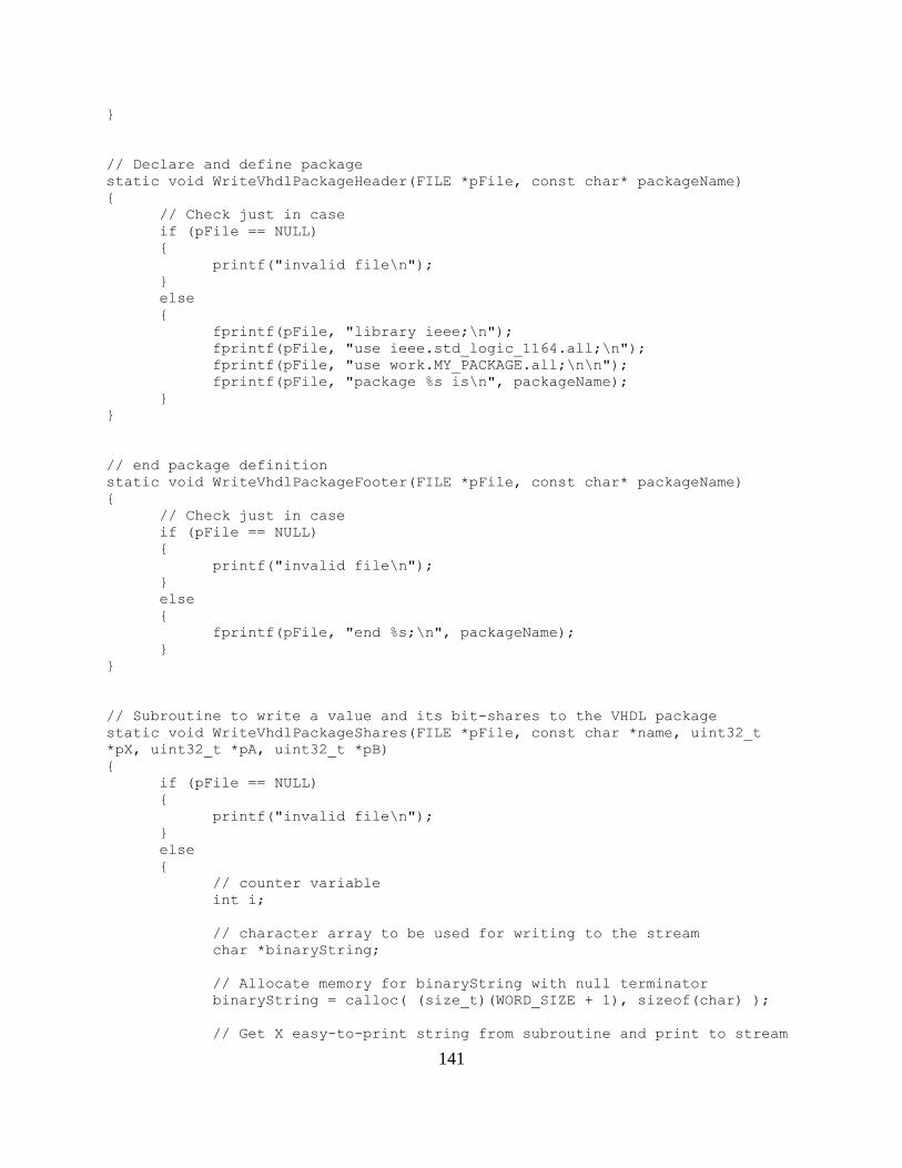
141
}
// Declare and define package
static void WriteVhdlPackageHeader(FILE *pFile, const char* packageName)
{
// Check just in case
if (pFile == NULL)
{
printf("invalid file\n");
}
else
{
fprintf(pFile, "library ieee;\n");
fprintf(pFile, "use ieee.std_logic_1164.all;\n");
fprintf(pFile, "use work.MY_PACKAGE.all;\n\n");
fprintf(pFile, "package %s is\n", packageName);
}
}
// end package definition
static void WriteVhdlPackageFooter(FILE *pFile, const char* packageName)
{
// Check just in case
if (pFile == NULL)
{
printf("invalid file\n");
}
else
{
fprintf(pFile, "end %s;\n", packageName);
}
}
// Subroutine to write a value and its bit-shares to the VHDL package
static void WriteVhdlPackageShares(FILE *pFile, const char *name, uint32_t
*pX, uint32_t *pA, uint32_t *pB)
{
if (pFile == NULL)
{
printf("invalid file\n");
}
else
{
// counter variable
int i;
// character array to be used for writing to the stream
char *binaryString;
// Allocate memory for binaryString with null terminator
binaryString = calloc( (size_t)(WORD_SIZE + 1), sizeof(char) );
// Get X easy-to-print string from subroutine and print to stream
142
Uint32toBinaryString(pX, binaryString);
fprintf(pFile, "\tconstant %s: std_logic_vector(31 downto 0) :=
\"%s\";\n\n", name, binaryString);
// Get XA(1) easy-to-print strings from subroutine and print to
stream
Uint32toBinaryString(&pA[0], binaryString);
fprintf(pFile, "\tconstant %sA: DATA_ARRAY(1 to 32) := (\t\"%s\",
", name, binaryString);
// Get XA(2 to 31) easy-to-print strings from subroutine and
print to stream
for(i = 1; i < WORD_SIZE-1; i++)
{
Uint32toBinaryString(&pA[i], binaryString);
fprintf(pFile, "\"%s\",", binaryString);
if((i % 2) == 1)
{
fprintf(pFile, "\n\t\t\t\t\t\t\t\t\t\t\t\t\t\t");
}
else
{
fprintf(pFile, " ");
}
}
// Get XA(32) easy-to-print strings from subroutine and print to
stream
Uint32toBinaryString(&pA[31], binaryString);
fprintf(pFile, "\"%s\");\n\n", binaryString);
// Get XB(1) easy-to-print strings from subroutine and print to
stream
Uint32toBinaryString(&pB[0], binaryString);
fprintf(pFile, "\tconstant %sB: DATA_ARRAY(1 to 32) := (\t\"%s\",
", name, binaryString);
// Get XB(2 to 31) easy-to-print strings from subroutine and
print to stream
for(i = 1; i < WORD_SIZE-1; i++)
{
Uint32toBinaryString(&pB[i], binaryString);
fprintf(pFile, "\"%s\",", binaryString);
if((i % 2) == 1)
{
fprintf(pFile, "\n\t\t\t\t\t\t\t\t\t\t\t\t\t\t");
}
else
{
fprintf(pFile, " ");
}
}

143
// Get XB(32) easy-to-print strings from subroutine and print to
stream
Uint32toBinaryString(&pB[31], binaryString);
fprintf(pFile, "\"%s\");\n", binaryString);
// Free memory
free(binaryString);
}
}
// Subroutine to convert an unsigned 32-bit number to a char array for easy
printing
static void Uint32toBinaryString(uint32_t *pX, char *binaryString)
{
int i;
for(i = 0; i < WORD_SIZE; i++)
{
binaryString[i] = ASCII_NUMERIC_OFFSET + ( ((*pX) >> (31-i)) &
BIT_MASK );
}
}
main.c:
/*
* Author: Gerardo Zamora Garcia
* Copyright: AwwYiss!
*/
// Necessary system #includes
#include <stdio.h>
#include <stdlib.h>
#include <stdint.h>
// Necessary user #includes
#include "GenerateShares.h"
// Debug #define
#define DEBUG_MAIN ( 1 )
// Program's main function
int main(int argc, char *argv[])
{
// needed variables
uint32_t X, Y, XA[WORD_SIZE], XB[WORD_SIZE], YA[WORD_SIZE],
YB[WORD_SIZE];
returnCode codeX, codeY;
FILE *pFileX, *pFileY;
144
// Begin ROI
// read in X and Y
printf("Input X to Generate Shares: ");
scanf("%u", &X);
printf("Input Y to Generate Shares: ");
scanf("%u", &Y);
printf("\n");
// Generate Shares for X and Y
GenerateShares(&X, XA, XB);
GenerateShares(&Y, YA, YB);
// Write VHDL packages for X and Y
codeX = WriteVhdlFile(pFileX,"tb_Xshares", "XS", &X, XA, XB);
codeY = WriteVhdlFile(pFileY,"tb_Yshares", "YS", &Y, YA, YB);
#if ( DEBUG_MAIN == 1 )
switch(codeX)
{
case INCORRECT_SHARES:
printf("X: shares are not correct. Check GenerateShares
algorithm!\n");
break;
case ERROR_OPENING_FILE:
printf("X: error opening the file!\n");
break;
case SUCCESS:
printf("Borat X: Great Success *thumbs up*\n");
break;
}
switch(codeY)
{
case INCORRECT_SHARES:
printf("Y: shares are not correct. Check GenerateShares
algorithm!\n");
break;
case ERROR_OPENING_FILE:
printf("Y: error opening the file!\n");
break;
case SUCCESS:
printf("Borat Y: Great Success *thumbs up*\n");
break;
}
#endif // DEBUG_MAIN
// End ROI \o/
return 0;
}