Hardware and Engineering SLS – Safety Lockout System
67
Hardware and Engineering SLS – Safety Lockout System 11/01 AWB8710-1372GB 1st published 2001, edition 11/01 © Moeller GmbH, Bonn Author: Josef Hilger Translator: David Long All brand and product names are trademarks or registered trademarks of the owner concerned. All rights reserved, including those of the translation. No part of this manual may be reproduced in any form (printed, photocopy, microfilm or any otherprocess) or processed, duplicated or distributed by means of electronic systems without written permission of Moeller GmbH, Bonn. Subject to alterations without notice.
Transcript of Hardware and Engineering SLS – Safety Lockout System

Hardware and Engineering
SLS – Safety Lockout System
11/01 AWB8710-1372GB1st published 2001, edition 11/01
© Moeller GmbH, Bonn
Author: Josef HilgerTranslator: David Long
All brand and product names are trademarks or registered trademarks of the owner concerned.
All rights reserved, including those of the translation.
No part of this manual may be reproduced in any form (printed, photocopy, microfilm or any otherprocess) or processed, duplicated or distributed by means of electronic systems without written permission of Moeller GmbH, Bonn.
Subject to alterations without notice.
Moe
llerG
mbH
Safe
ty in
stru
ctio
nsWarning!Dangerous electrical voltage!
Before commencing the installation
• Disconnect the power supply of the device.
• Ensure that devices cannot be accidentally restarted.
• Verify isolation from the supply.
• Earth and short circuit the device.
• Cover or enclose any adjacent live components.
• Follow the engineering instructions (AWA) for the device concerned.
• Only suitably qualified personnel in accordance with EN 50110-1/-2 (VDE 0105 Part 100) may work on this device/system.
• Before installation and before touching the device ensure that you are free of electrostatic charge.
• The functional earth (FE) must be connected to the protective earth (PE) or the potential equalisation. The system installer is responsible for implementing this connection.
• Connecting cables and signal lines should be installed so that inductive or capacitive interference does not impair the automation functions.
• Install automation devices and related operating elements in such a way that they are well protected against unintentional operation.
• Suitable safety hardware and software measures should be implemented for the I/O interface so that an open circuit on the signal side does not result in undefined states in the automation devices.
• Ensure a reliable electrical isolation of the extra-low voltage of the 24 V supply. Only use power supply units complying with IEC 60364-4-41 (VDE 0100 Part 410) or HD384.4.41 S2.
• Deviations of the mains voltage from the rated value must not exceed the tolerance limits given in the specifications, otherwise this may cause malfunction and dangerous operation.
• Emergency stop devices complying with IEC/EN 60204-1 must be effective in all operating modes of the automation devices. Unlatching the emergency-stop devices must not cause a restart.
• Devices that are designed for mounting in housings or control cabinets must only be operated and controlled after they have been installed and with the housing closed. Desktop or portable units must only be operated and controlled in enclosed housings.
• Measures should be taken to ensure the proper restart of programs interrupted after a voltage dip or failure. This should not cause dangerous operating states even for a short time. If necessary, emergency-stop devices should be implemented.
• Wherever faults in the automation system may cause injury or material damage, external measures must be implemented to ensure a safe operating state in the event of a fault or malfunction (for example, by means of separate limit switches, mechanical interlocks etc.).
• Depending on their degree of protection, frequency inverters may contain live bright metal parts, moving or rotating components or hot surfaces during and immediately after operation.
• Removal of the required covers, improper installation or incorrect operation of motor or frequency inverter may cause the failure of the device and may lead to serious injury or damage.
• The applicable national accident prevention and safety regulations apply to all work carried on live frequency inverters.
• The electrical installation must be carried out in accordance with the relevant regulations (e. g. with regard to cable cross sections, fuses, PE).
• Transport, installation, commissioning and maintenance work must be carried out only by qualified personnel (IEC 60364, HD384 and national occupational safety regulations).
• Installations containing frequency inverters must be provided with additional monitoring and protective devices in accordance with the applicable safety regulations. Modifications to the frequency inverters using the operating software are permitted.
I
II
• All covers and doors must be kept closed during operation.
• To reduce the hazards for people or equipment, the user must include in the machine design measures that restrict the consequences of a malfunction or failure of the drive (increased motor speed or sudden standstill of motor). These measures include:
– Other independent devices for monitoring safety-related variables (speed, travel, end positions etc.).
– Electrical or non-electrical system-wide measures (electrical or mechanical interlocks).
– Never touch live parts or cable connections of the frequency inverter after it has been disconnected from the power supply. Due to the charge in the capacitors, these parts may still be live after disconnection. Fit appropriate warning signs.

11/01 AWB8710-1372GB
Contents
1
About this manual 3Abbreviations and symbols 3
1 SLS General Information 5General safety instructions 7Electrical protection of the SLS 7Intended usage and limitations of the SLS 7System overview 8General module description 10– Power box (PB) 10– Control box (CB) 10– Disconnect switches (DS, DS2, ES, GS) 11Optional modules 11– Marshalling box(es) (MB) 11– Time delay module 11
2 Engineering Information 13SLS system component requirement 13Site of installation of the SLS 13SLS control voltage 13Cables and wiring for SLS interconnection 13– Allowed maximum cable lengths 13– Configuration requirements 13
3 System Components 15Power Box 15Control Box 17Marshalling box 19
4 Commissioning Instructions 21Start up of SLS 21Normal operation 22– How to stop and restart the SLS 22– Manual restart of SLS and machinery 22Function of internal components 22– Control circuit protection devices 22– Voltage monitor PU3Z (K1A) in power box 23– Concentrator of inputs (Relays K1A to K4A)
in Control Box 24– Isolation monitoring (Relay K11A) in the control box 25– Confirmation relay (K12A) in control box 25Status of internal relays and indication lamps under normal working conditions 26

Contents 11/01 AWB8710-1372GB
2
5 Trouble Shooting 31Protection devices 31– CB “Q1“ in the Power Box 31– MCB “F1“ in Power Box 32– MCB “F2“ in Power Box 32– MCB “F3“ or “F5“ in Control Box 32– MCB “F2“, “F4“ or “F6“ in Control Box 32Voltage monitor in power box 33Concentrated Relay (K1A to K4A) in Control Box 38Isolation monitoring relay K11A 44Confirmation relay K12A of voltage monitor PU3Z 46Indication lamps on the control box 49– SLS ready 49– Disconnect off 49Disconnect switch 49
6 General Information for the Replacement of Sealed Units 51Module types in CI-enclosure or sheet steel enclosures 51Module types as fully withdrawable units of the MODAN6000MCC 51
Appendix 53Technical Data 53– SLS, Cables/Interconnection 53– SLS in Totally Insulated CI Enclosure 54– SLS in Sheet Steel Enclosure 55– SLS in Fully Withdrawable MODAN6000 Unit 56– MDM Motor Control Centre and
Power Distribution Section 56Dimensions 57– Power Box, Power/Control Box 57– Control Box, Marshalling Box 59– Disconnect Switch, Emergency-Stop Button 60Declaration of Conformity 61
Index 63

11/01 AWB8710-1372GB
3
About this manual
This manual describes the installation, operation and function of the components required for the Moeller Safety Lockout System (SLS). It provides a detailed description of the function and the practical usage.
Read this manual thoroughly before installing and commissioning the SLS system and its components.
Abbreviations and symbols
Abbreviations and symbols with the following meanings are described in this manual: In order to improve the readability, the title of the chapter is
indicated on the top of the left-hand page and the current section is indicated on the top of the right-hand page. Pages where chapters commence and blank pages at the end of the chapter are an exception.
SLS Safety Lockout System
CB Control Box
CB2 Control Box with 2 inputs
CB4 Control Box with 4 inputs
CB8 Control Box with 8 inputs
MB Marshalling Box
MB8 Marshalling Box – 8 inputs
MB16 Marshalling Box – 16 inputs
PB Power Box
DS Disconnection Switch
DS2 Disconnection Switch 2 for guard switch connection
GS Guard switch
ES Emergency-stop Switch
NO Normally open contact (make contact)
NC Normally closed contact (break contact)
h Makes you aware of interesting tips and additional information
Attention!warns about the possibility of major material damage and minor injury.
Warning!warns about the possibility of major material damage and severe injury or death.

11/01 AWB8710-1372GB
4

11/01 AWB8710-1372GB
5
1 SLS General Information
The Safety Lockout System (hereinafter SLS) is a safety component according to the definition of the Machinery Directive 98/37/EC.
If the system is installed and connected as specified in this user manual, and conform to the installation standards (IEC 463..., NEC NFPA70 and other national standards where stipulated), it fulfils the requirements of category 4 according to EN 954-1.
The Safety Lockout System is a “System“ for “Prevention of unexpected start-up of the Machinery to which it is connected“, with visual confirmation of the zero-energy status of the SLS output.
The power is disconnected using several safety principles including redundancy, positively driven contacts, dual channel command, etc. for optimum safety. The voltage supply of the machinery is controlled and the status indicated visually.
The system disconnects the voltage to the machinery in three stages:
• Initially, the signals from the disconnect switches are actuated in a safety circuit with two channels. Delayed closing or opening of one of the 2 channels which result in the non-operation of the PB before the problem is resolved or both channels are reset. The system indicates a failure.
• The main contactors are switched off resulting from the disconnect command. A voltage monitor controls the status of voltage supply behind the main contactors on the machinery supply side. If a voltage of more than 10 V remains on the output of the PB (machinery side), there will be no visual confirmation of the zero-energy state of the SLS output.
• The safe status of power interruption is confirmed by a green light on DS, DS2, which can only light up if the voltage monitor indicates no voltage supply for the machinery.
Note that the most important rule to be observed by the machinery operators is:
The system is designed to be flexible, in order to assure use with various machinery types and sizes, and to ensure world-wide installation. Therefore, all technical and safety aspects as well as national and local regulations which may apply have to be considered.
NO LIGHT NO ENTRY

SLS General Information 11/01 AWB8710-1372GB
6
Figure 1: Risk assessment graph
P1
P2
P1
P2
F1
F2
S1
S2
B 1 2 3 4
Risk graph
Starting point for risk assessment
S – Severity of injuryS1 – Slight injuryS2 – Serious irreversible injury to one or several persons, or death
F – Frequency and time of exposure to the hazardF1 – Rarely to often and/or a short durationF2 – Frequent to continuous and/ or a long duration
P – Possibility of avoiding hazardsP1 – possible under specific conditionsP2 – Scarcely possible
Preferred category for reference pointsPossible categories which require additional measures, e.g. over-dimensioningOver-dimensioned categories for the risk concerned
Category in accordance with EN 954-1
Category selection
What does category 4 mean?
Category Requirements
B Protective/control systems and components taking into account the operating and ambient temperatures.
1 Additional to “B“: Well-tried components and principles that meet the safety requirements
2 Additional to “B“: Checking of the safety function by the control system at suitable intervals
3 Additional to “B“: Single fault safety and fault detection whenever practicable in accordance with the state of technology
4 Additional to “B“: Single fault safety and fault detection or no hazard due to accumulation of faults

11/01 AWB8710-1372GB General safety instructions
7
General safety instructions
Electrical protection of the SLS
The SLS must also be protected against
• Overvoltage caused by mains voltage spikes (caused for example by lightning strikes).
• Harmonics (Contact Moeller for relevant values).• Input voltage deviations exceeding +/– 10 %.
The PB must be additionally protected in accordance to the local installation standards and codes which apply.
Intended usage and limitations of the SLS
Warning!Moeller cannot be held liable for any injury, damage or consequential damages as a result of incorrect connection, fitting or installation. All connection, fitting and maintenance work may only be performed by suitably qualified personnel.
Never carry out electrical work on the devices while the power supply is switched on.
Always follow the safety rules:
• Switch off and ground.• Secure against restart.• Verify isolation from the supply.• Cover adjacent live parts.• Only suitably qualified personnel may transport, install,
test, operate, repair and maintain the Safety Lockout System.
Warning!• The SLS is not intended for use to
– Start up machinery.– Stop machinery by using a disconnect switch.– Replace a device for disconnecting electrical
equipment according to IEC/EN 60204-1 clause 5.3 and 5.5.
• The machinery must have their own start/stop commands, and may not start automatically when the SLS connects the power supply to the machinery.
• Safety-related interruption in accordance with EN 954-1 Category 4, refers exclusively to the Safety Lockout System, consisting of the Power Box, Control Box, Marshalling Box and Disconnect Switch modules. External commands such as “Disconnect“ effect only a single, not-safety-related interruption. For safe interruptions, disconnect switches must be used. The PLC-signals of the SLS modules are exclusively for the provision of status signals and not intended for additional safe interrupt commands.
• The power output circuit of the SLS is intended to interrupt the power supply to the machinery. The user (or the machine manufacturer) has to make sure, that the power supply output which has been interrupted will not cause risk to life or limb, or any damage.

SLS General Information 11/01 AWB8710-1372GB
8
System overview
The graphic shown below is a typical example of a Safety Lockout System.
Figure 2: SLS overview
1 2 3 4 5 6 7 8 9 10 11 PE
1
-X01
1 2 3 4 5 6 7 8 9 10 PE-X1 1 2 3 4 5 6 7 8 9 10 PE-X2 1 2 3 4 5 6 7 8 9 10 PE-X3 1 2 3 4 5 6 7 8 9 10 PE-X4
1
1
2
3
4
5
6
11
12
11
12
31
32
21
22
1
2
3
4
11
12
11
12
13
14
5
6
7 *
8
9
10
X2H1
X1
X2H1
X1
2 3 4 5 6 7 8 9 10 PE-X5 1 2 3 4 5 6 7 8 9 10 PE-X6 1 2 3 4 5 6 7 8 9 10 PE-X7 1 2 3 4 5 6 7 8 9 10 PE-X8
*
L1L2L3NPE
L1L2L3NPE
-X01
-X02
-X02
-X03
-X032 3 4 5 6 7
1 2 3 4 5 6 PE
1 2 3 4 5 6 PE 1 2 3 4 5 6 7 8 0V 24V PE
8 9 10 11 PE I1 I2 I3 I4 I5 I6 I7 I8 1 2 3 4 CO 0V 24V PE
X1-INPOWER BOXin CI-Enclosure
CONTROL BOXwith 8 Inputs
Disconnect Switch(3 N0/1 NC)
Disconnect Switch(4 N0/2 NC)
Emergency Stop Guard Switch Supply byExternalVoltage
* AC15 230 V AC 5 A
X1-OUT
Interconnection PB to CB Interconnection PB to CB Interface to PLC
Interface to PLC
closed contact whenzero voltage detected
11/01 AWB8710-1372GB System overview
9
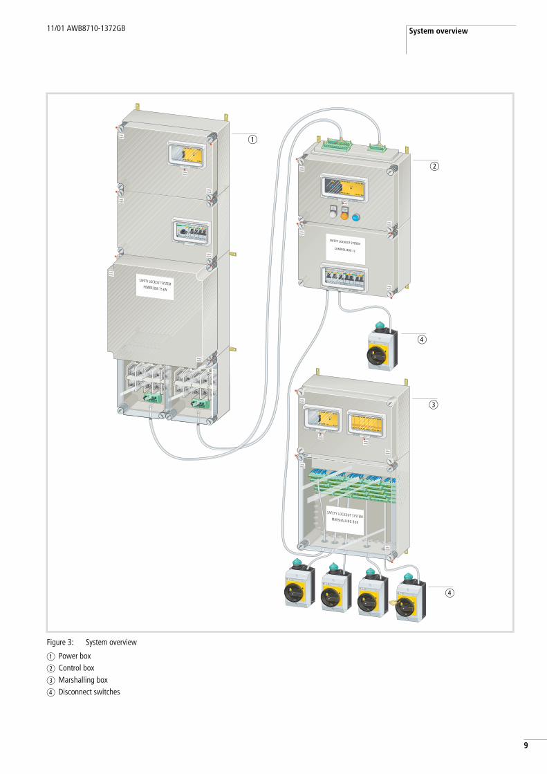
Figure 3: System overview
a Power boxb Control boxc Marshalling boxd Disconnect switches
SafetySealed
SafetySealed
SafetySealed
SAFETY LOCKOUT SYSTEMMARSHALLING BOX
SafetySealed
SLSREADY
SafetySealed
SafetySealed
SafetySealed
SafetySealed
SafetySealed
DISCONNECTOFF
SAFETY LOCKOUT SYSTEM
CONTROL BOX 12
SafetySealed
SafetySealed
3
4
4
2
1
SAFETY LOCKOUT SYSTEMPOWER BOX 75 kW
SafetySealed
SafetySealed
SafetySealed
SafetySealed
SafetySealed
SafetySealed
SafetySealed
a
b
d
c
d
SLS General Information 11/01 AWB8710-1372GB
10
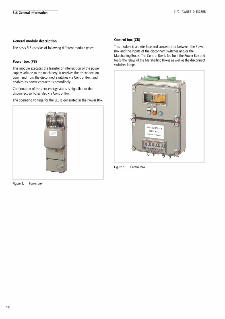
General module description
The basis SLS consists of following different module types:
Power box (PB)
This module executes the transfer or interruption of the power supply voltage to the machinery. It receives the disconnection command from the disconnect switches via Control Box, and enables its power contactor’s accordingly.
Confirmation of the zero-energy status is signalled to the disconnect switches also via Control Box.
The operating voltage for the SLS is generated in the Power Box.
Control box (CB)
This module is an interface and concentrator between the Power Box and the inputs of the disconnect switches and/or the Marshalling Boxes. The Control Box is fed from the Power Box and feeds the relays of the Marshalling Boxes as well as the disconnect switches lamps.
Figure 4: Power box
Figure 5: Control Box
11/01 AWB8710-1372GB Optional modules
1
1Disconnect switches (DS, DS2, ES, GS)
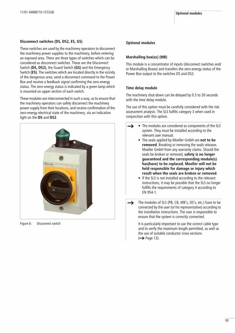
These switches are used by the machinery operators to disconnect the machinery power supplies to the machinery, before entering an exposed area. There are three types of switches which can be considered as disconnect switches. These are the Disconnect Switch (DS, DS2), the Guard Switch (GS) and the Emergency Switch (ES). The switches which are located directly in the vicinity of the dangerous area, send a disconnect command to the Power Box and receive a feedback signal confirming the zero-energy status. The zero-energy status is indicated by a green lamp which is mounted on upper section of each switch.
These modules are interconnected in such a way, as to ensure that the machinery operators can safely disconnect the machinery power supply from their locations, and receive confirmation of the zero-energy electrical state of the machinery, via an indication light on the DS and DS2.
Optional modules
Marshalling box(es) (MB)
This module is a concentrator of inputs (disconnect switches and/or Marshalling Boxes) and transfers the zero-energy status of the Power Box output to the switches DS and DS2.
Time delay module
The machinery shut-down can be delayed by 0.5 to 30 seconds with the time delay module.
The use of this option must be carefully considered with the risk assessment analysis. The SLS fulfills category 3 when used in conjunction with this option.
Figure 6: Disconnect switch
h • The modules are considered as components of the SLS system. They must be installed according to the relevant user manual.
• The seals applied by Moeller GmbH are not to be removed. Breaking or removing the seals releases Moeller GmbH from any warranty claims. Should the seals be broken or removed, safety is no longer guaranteed and the corresponding module(s) has(have) to be replaced. Moeller will not be held responsible for damage or injury which result when the seals are broken or removed.
• If the SLS is not installed according to the relevant instructions, it may be possible that the SLS no longer fulfills the requirements of category 4 according to EN 954-1.
h The modules of SLS (PB, CB, MB’s, DS’s, etc.) have to be connected by the user (or his representative) according to the installation instructions. The user is responsible to ensure that the system is correctly connected.
It is particularly important to use the correct cable type and to verify the maximum length permitted, as well as the use of suitable conductor cross-sections (a Page 13).

11/01 AWB8710-1372GB
12

11/01 AWB8710-1372GB
3
12 Engineering Information
Please ensure that the load which your system presents to the SLS does not exceed the power box specifications.
SLS system component requirement
The SLS configuration consists of:
• PB: one module is required• CB: one module is required• DS, DS2, GS, ES: quantity depending on the application
(minimum 1)
Site of installation of the SLS
• PB must be installed in the direct vicinity of the machinery electrical switch-cabinet. The input side of PB has to be connected directly after the main supply disconnect switch and machinery protection; the machinery (load) is connected to the output side of PB.
• The disconnect switches have to be placed at all locations as defined by the machinery manufacturer, in order to ensure that the operators can easily switch off the machinery supply voltage before entering into an exposed/dangerous area.
• MB’s as connection points for signals coming from a lower level, must be fitted at locations to optimise the total cable length between the disconnect switches and PB.
SLS control voltage
The control voltage for SLS is generated internally by a 400 V or 480/230 V control transformer. The primary voltage for the transformer has to be selected by taps on the terminal block XT, and must correspond to the rated mains voltage of the system.
Cables and wiring for SLS interconnection
All connections between PB, CB and MB’s should be made with 1.5 mm2 (AWG 16) to 2.5 mm2 (AWG 13) wires.
The connections to the disconnect switches have to be made with 0.75 mm2 (AWG 18) to 1.5 mm2 (AWG 16) wires.
Shielded cables are not necessary for correct operation of the Safety Lockout System.
If you have distances of more than 1000 m or more than 8 disconnect switches, please contact Moeller for further possibilities.
Allowed maximum cable lengths
The lengths of the cables which can be used can be taken from the following table:
Configuration requirements
If your design includes the optional MB, the max. cable length from CB to each disconnect switch may not exceed 300 m (as opposed to 800 m as stated in the table). If you require longer distances, please contact Moeller.
Figure 7: Terminal block XT
From To Maximum distance[m]
Power Box Control Box approx. 200
Control Box (max. 8 i/ps)
Switches (DS/ES/GS) approx. 800
Total approx. 1000
Combined Power/Control Box
Power/Control Box Switches (DS/ES/GS) approx. 800

11/01 AWB8710-1372GB
14
11/01 AWB8710-1372GB
5
13 System Components
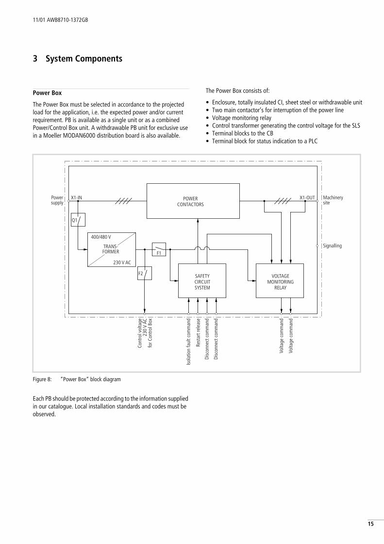
Power Box
The Power Box must be selected in accordance to the projected load for the application, i.e. the expected power and/or current requirement. PB is available as a single unit or as a combined Power/Control Box unit. A withdrawable PB unit for exclusive use in a Moeller MODAN6000 distribution board is also available.
The Power Box consists of:
• Enclosure, totally insulated CI, sheet steel or withdrawable unit• Two main contactor’s for interruption of the power line• Voltage monitoring relay• Control transformer generating the control voltage for the SLS• Terminal blocks to the CB• Terminal block for status indication to a PLC
Each PB should be protected according to the information supplied in our catalogue. Local installation standards and codes must be observed.
Figure 8: “Power Box“ block diagram
Q1
F2
F1
400/480 V
230 V AC
POWERCONTACTORS
SAFETYCIRCUITSYSTEM
VOLTAGEMONITORING
RELAY
X1-IN X1-OUT
TRANS-FORMER
Powersupply
Machinerysite
Signalling
Cont
rol v
olta
ge23
0 V
ACfo
r Con
trol B
ox
Isol
atio
n fa
ult c
omm
and
Rest
art r
elea
se
Disc
onne
ct c
omm
and
Disc
onne
ct c
omm
and
Volta
ge c
omm
and
Volta
ge c
omm
and
System Components 11/01 AWB8710-1372GB
16
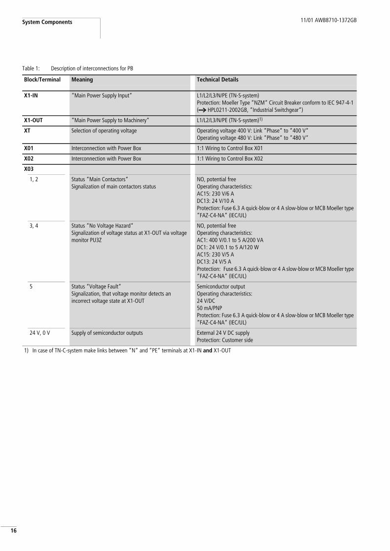
Table 1: Description of interconnections for PB
Block/Terminal Meaning Technical Details
X1-IN “Main Power Supply Input“ L1/L2/L3/N/PE (TN-S-system)Protection: Moeller Type “NZM“ Circuit Breaker conform to IEC 947-4-1 (a HPL0211-2002GB, “Industrial Switchgear“)
X1-OUT “Main Power Supply to Machinery“ L1/L2/L3/N/PE (TN-S-system)1)
XT Selection of operating voltage Operating voltage 400 V: Link “Phase“ to “400 V“Operating voltage 480 V: Link “Phase“ to “480 V“
X01 Interconnection with Power Box 1:1 Wiring to Control Box X01
X02 Interconnection with Power Box 1:1 Wiring to Control Box X02
X03
1, 2 Status “Main Contactors“Signalization of main contactors status
NO, potential freeOperating characteristics: AC15: 230 V/6 ADC13: 24 V/10 AProtection: Fuse 6.3 A quick-blow or 4 A slow-blow or MCB Moeller type “FAZ-C4-NA“ (IEC/UL)
3, 4 Status “No Voltage Hazard“Signalization of voltage status at X1-OUT via voltage monitor PU3Z
NO, potential freeOperating characteristics:AC1: 400 V/0.1 to 5 A/200 VADC1: 24 V/0.1 to 5 A/120 WAC15: 230 V/5 ADC13: 24 V/5 AProtection: Fuse 6.3 A quick-blow or 4 A slow-blow or MCB Moeller type “FAZ-C4-NA“ (IEC/UL)
5 Status “Voltage Fault“Signalization, that voltage monitor detects an incorrect voltage state at X1-OUT
Semiconductor outputOperating characteristics:24 V/DC50 mA/PNPProtection: Fuse 6.3 A quick-blow or 4 A slow-blow or MCB Moeller type “FAZ-C4-NA“ (IEC/UL)
24 V, 0 V Supply of semiconductor outputs External 24 V DC supplyProtection: Customer side
1) In case of TN-C-system make links between “N“ and “PE“ terminals at X1-IN and X1-OUT
11/01 AWB8710-1372GB Control Box
7
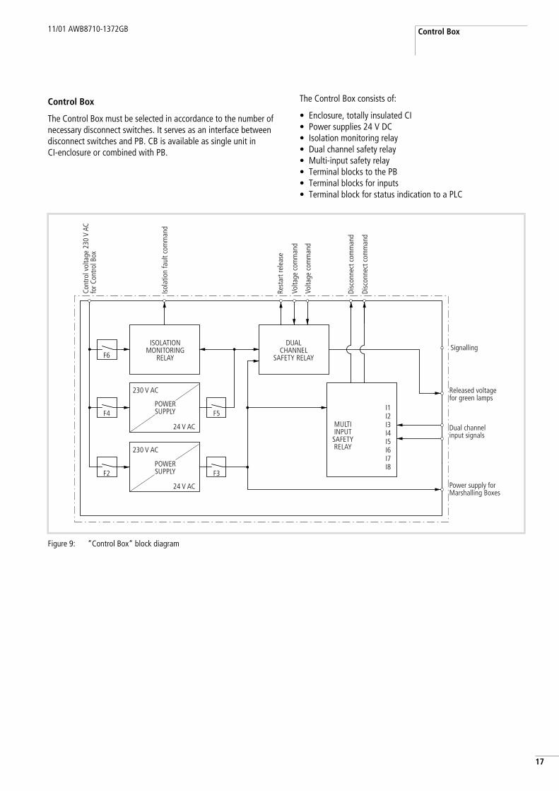
1Control Box
The Control Box must be selected in accordance to the number of necessary disconnect switches. It serves as an interface between disconnect switches and PB. CB is available as single unit in CI-enclosure or combined with PB.
The Control Box consists of:
• Enclosure, totally insulated CI• Power supplies 24 V DC• Isolation monitoring relay• Dual channel safety relay• Multi-input safety relay• Terminal blocks to the PB• Terminal blocks for inputs• Terminal block for status indication to a PLC
Figure 9: “Control Box“ block diagram
F6
F4
F2
F5I1I2I3I4I5I6I7I8
F3
230 V AC
24 V AC
230 V AC
24 V AC
ISOLATIONMONITORING
RELAY
DUALCHANNEL
SAFETY RELAY
MULTIINPUT
SAFETYRELAY
POWERSUPPLY
POWERSUPPLY
Signalling
Released voltagefor green lamps
Dual channelinput signals
Power supply forMarshalling Boxes
Cont
rol v
olta
ge 2
30 V
AC
for C
ontro
l Box
Isol
atio
n fa
ult c
omm
and
Rest
art r
elea
se
Disc
onne
ct c
omm
and
Disc
onne
ct c
omm
and
Volta
ge c
omm
and
Volta
ge c
omm
and
System Components 11/01 AWB8710-1372GB
18
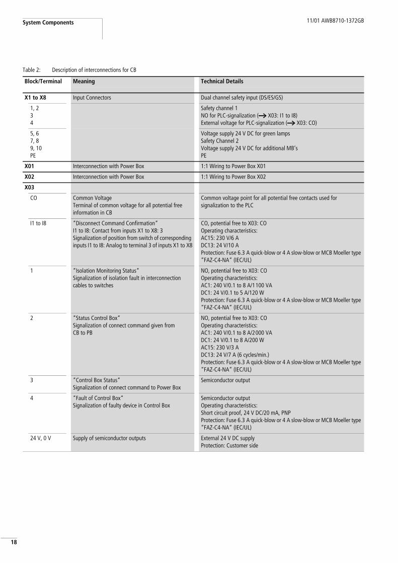
Table 2: Description of interconnections for CB
Block/Terminal Meaning Technical Details
X1 to X8 Input Connectors Dual channel safety input (DS/ES/GS)
1, 234
Safety channel 1NO for PLC-signalization (a X03: I1 to I8)External voltage for PLC-signalization (a X03: CO)
5, 6 7, 89, 10 PE
Voltage supply 24 V DC for green lampsSafety Channel 2Voltage supply 24 V DC for additional MB’s PE
X01 Interconnection with Power Box 1:1 Wiring to Power Box X01
X02 Interconnection with Power Box 1:1 Wiring to Power Box X02
X03
CO Common VoltageTerminal of common voltage for all potential free information in CB
Common voltage point for all potential free contacts used for signalization to the PLC
I1 to I8 “Disconnect Command Confirmation“I1 to I8: Contact from inputs X1 to X8: 3Signalization of position from switch of corresponding inputs I1 to I8: Analog to terminal 3 of inputs X1 to X8
CO, potential free to X03: COOperating characteristics:AC15: 230 V/6 ADC13: 24 V/10 AProtection: Fuse 6.3 A quick-blow or 4 A slow-blow or MCB Moeller type “FAZ-C4-NA“ (IEC/UL)
1 “Isolation Monitoring Status“Signalization of isolation fault in interconnection cables to switches
NO, potential free to X03: COOperating characteristics:AC1: 240 V/0.1 to 8 A/1100 VADC1: 24 V/0.1 to 5 A/120 WProtection: Fuse 6.3 A quick-blow or 4 A slow-blow or MCB Moeller type “FAZ-C4-NA“ (IEC/UL)
2 “Status Control Box“Signalization of connect command given from CB to PB
NO, potential free to X03: COOperating characteristics:AC1: 240 V/0.1 to 8 A/2000 VADC1: 24 V/0.1 to 8 A/200 WAC15: 230 V/3 ADC13: 24 V/7 A (6 cycles/min.)Protection: Fuse 6.3 A quick-blow or 4 A slow-blow or MCB Moeller type “FAZ-C4-NA“ (IEC/UL)
3 “Control Box Status“Signalization of connect command to Power Box
Semiconductor output
4 “Fault of Control Box“Signalization of faulty device in Control Box
Semiconductor outputOperating characteristics:Short circuit proof, 24 V DC/20 mA, PNPProtection: Fuse 6.3 A quick-blow or 4 A slow-blow or MCB Moeller type “FAZ-C4-NA“ (IEC/UL)
24 V, 0 V Supply of semiconductor outputs External 24 V DC supplyProtection: Customer side
11/01 AWB8710-1372GB Marshalling box
9
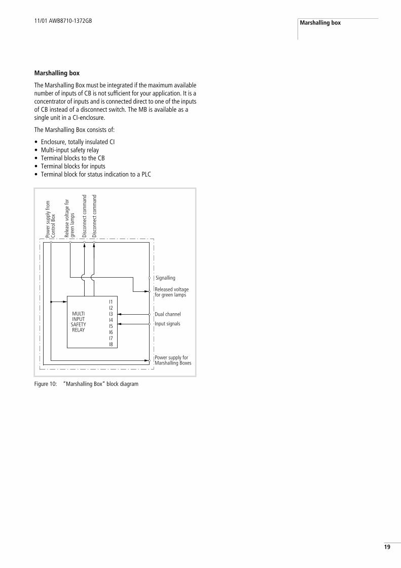
1Marshalling box
The Marshalling Box must be integrated if the maximum available number of inputs of CB is not sufficient for your application. It is a concentrator of inputs and is connected direct to one of the inputs of CB instead of a disconnect switch. The MB is available as a single unit in a CI-enclosure.
The Marshalling Box consists of:
• Enclosure, totally insulated CI• Multi-input safety relay• Terminal blocks to the CB• Terminal blocks for inputs• Terminal block for status indication to a PLC
Figure 10: “Marshalling Box“ block diagram
I1I2I3I4I5I6I7I8
MULTIINPUT
SAFETYRELAY
Signalling
Released voltagefor green lamps
Dual channel
Input signals
Power supply forMarshalling Boxes
Disc
onne
ct c
omm
and
Disc
onne
ct c
omm
and
Pow
er s
uppl
y fro
mCo
ntro
l Box
Rele
ase
volta
ge fo
rgr
een
lam
ps

System Components 11/01 AWB8710-1372GB
20
Table 3: Description of interconnections for MB
Block/Termina Meaning Technical Details
X1 to X16 Input Connectors Dual channel safety input (DS/ES/GS)
1, 234
Safety channel 1NO for PLC-signalization (a X03: I1 to I16)External voltage for PLC-signalization (a X03: CO)
5, 6 7, 8 9, 10 PE
Voltage supply 24 V DC for green lampsSafety channel 2Voltage supply 24 V DC for add. MB’s PE
X01 Interconnection with Control Box 1:1 Wiring to Input X1 to X8
X03
CO Common VoltageTerminal of common voltage for all potential free information in CB
Common voltage point for all potential free contacts used for signalization to the PLC
I1 to I16 “Disconnect Command Confirmation“I1 to I16: Contact from inputs X1 to X16: 3Signalization of position from switch of corresponding inputs I1 to I8: Analog to terminal 3 of inputs X1 to X8
NO, potential free to X03: COOperating characteristics:AC15: 230 V/6 ADC13: 24 V/10 AProtection: Fuse 6.3 A quick-blow or 4 A slow-blow or MCB Moeller type “FAZ-C4-NA“ (IEC/UL)
2 “Status Marshalling Box“Signalization of connect command given from CB to PB
NO, potential free to X03: COOperating characteristics:AC1: 240 V/0.1 to 8 A/2000 VADC1: 24 V/0.1 to 8 A/200 WAC15: 230 V/3 ADC13: 24 V/7 A (6 cycles/min.)Protection: Fuse 6.3 A quick-blow or 4 A slow-blow or MCB Moeller type “FAZ-C4-NA“ (IEC/UL)
3 “Marshalling Box Status“Signalization of connect command to Power Box
Semiconductor output
4 “Fault of Marshalling Box“Signalization of faulty device in Marshalling Box
Semiconductor outputOperating characteristics:Short circuit proof, 24 V DC/20 mA, PNPProtection: Fuse 6.3 A quick-blow or 4 A slow-blow or MCB Moeller type “FAZ-C4-NA“ (IEC/UL)
24 V, 0 V Supply of semiconductor outputs External 24 V DC supplyProtection: Customer side

11/01 AWB8710-1372GB
1
24 Commissioning Instructions
Start up of SLS
• The main supply disconnect switch must be in the “OFF“ position.
• Select the operating voltage by using the link of terminal block XT in PB. If theoperating voltage on site is 400 V plug link in position “Phase“ – “400 V“. If operating voltage on site is 480 V plug link in position “Phase“ – “480 V“.
• Make current adjustment at PKZM0 (Q1) in PB according to selection of operating voltage (a label close to XT).
• Turn at least one of the disconnect switches to the “OFF“ position (disconnect switches are padlockable in the “OFF“ position).
• All MCB’s and protection circuit breakers in PB and CB must be switched “ON“.
• Close the main supply disconnect switch. This causes the SLS to be energized, and the green verification light of all DS, DS2 which are in the “OFF“ position will light up.
• Close all disconnect switches. Every time a DS or DS2 is closed, its verification light turns off.
• If all disconnect switches are in the “ON“ position:– All the green verification lights are de-energized.– PB main contactors are energized and the input voltage of PB
is transferred to the output side.
Warning!Before you power up the system, ensure that the wiring and cabling are connected according to the instructions in this manual.
h During start-up or after voltage interruption, the SLS will self-check the function of its internal systems. This self-test requires approximately 45 s for completion; the system cannot be started during this time.
If all disconnect switches are in the “ON“ position during start-up, the SLS will not turn on before at least one of the disconnect switches has been turned “OFF“ and then turned back “ON“.
1) F2 in PB does not apply in combined Power/Control Box2) F3 and F5 in CB does not apply in upgraded CB’s
Figure 11: “Start-up“ flow diagram
Switch on Q1 in PB
(400/480 V AC)
Control transformer supplied
Control voltage 230 V AC
switched on
Switch on F1 in PB
(230 V AC)
Control circuitand PU3Z supplied
PU3Z K1A powered“Power” LED on PU3Z K1A active
Switch on F2 in PB1)
(230 V AC)
Control boxsupplied
Start of delay time before start-up of
SLS 45 s
Switch on F2 in CB
(230 V AC)
PS 24 V DCfor safety relay
powered
Switch on F3 in CB2)
(24 V DC)
24 V DCfor safety relay
switched on
PNOZX2 (K12A)powered
“Power” LED on
PNOZX2 activeLED‘s of channels
are green
PNOZXM1 (K1A)powered
“Power” LED on
Switch on F4 in CB
(230 V AC)
PS 24 V DCfor green lamps
powered
All input circuits closed, green LED‘s
PNOZXM1 active
Switch on F5 in CB2)
(24 V DC)
24 V DCfor green lamps
switched on
Lamp “Disconnect Off”
switched off
Switch on F6 in CB
(230 V AC)
Isolation monitor K11A supplied
“Power” LED on
Lamp “SLS Ready”switched on
Commissioning Instructions 11/01 AWB8710-1372GB
22
Normal operation
How to stop and restart the SLS
The following sequence applies if the SLS has to interrupt the power supply voltage to the machine:
• The machinery must be stopped using its stop command.• The operator who needs to work in an exposed area has to turn
off and padlock the corresponding disconnect switch. The SLS goes into the “Disconnected Status“.
• If (and only if) the zero-energy status is verified, the verification light comes “ON“ and the operator is allowed to enter the corresponding exposed area. No Light => No Entry.
• When work has been completed, the padlock can be removed and the disconnect switch can be turned to the “ON“ position. Then the verification light turns “OFF“.
• When all disconnect switches are in the “ON“ position, PB transfers the main voltage to its output and the machinery can be started again.
Manual restart of SLS and machinery
• If the SLS is turned “OFF“, the machinery can no longer be supplied.
• The SLS can be turned “ON“, switching back all switches in “ON“ position.
• If the SLS is turned “ON“ again, the machinery may not start without a manual command from the machinery operator. These functions are to be provided by the machinery manufacturer.
Function of internal components
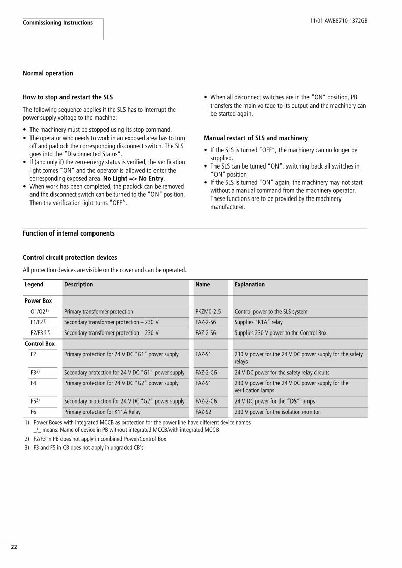
Control circuit protection devices
All protection devices are visible on the cover and can be operated.
Legend Description Name Explanation
Power Box
Q1/Q21) Primary transformer protection PKZM0-2.5 Control power to the SLS system
F1/F21) Secondary transformer protection – 230 V FAZ-2-S6 Supplies “K1A“ relay
F2/F31) 2) Secondary transformer protection – 230 V FAZ-2-S6 Supplies 230 V power to the Control Box
Control Box
F2 Primary protection for 24 V DC “G1“ power supply FAZ-S1 230 V power for the 24 V DC power supply for the safety relays
F33) Secondary protection for 24 V DC “G1“ power supply FAZ-2-C6 24 V DC power for the safety relay circuits
F4 Primary protection for 24 V DC “G2“ power supply FAZ-S1 230 V power for the 24 V DC power supply for the verification lamps
F53) Secondary protection for 24 V DC “G2“ power supply FAZ-2-C6 24 V DC power for the “DS“ lamps
F6 Primary protection for K11A Relay FAZ-S2 230 V power for the isolation monitor
1) Power Boxes with integrated MCCB as protection for the power line have different device names _/_ means: Name of device in PB without integrated MCCB/with integrated MCCB
2) F2/F3 in PB does not apply in combined Power/Control Box3) F3 and F5 in CB does not apply in upgraded CB’s
11/01 AWB8710-1372GB Function of internal components
3
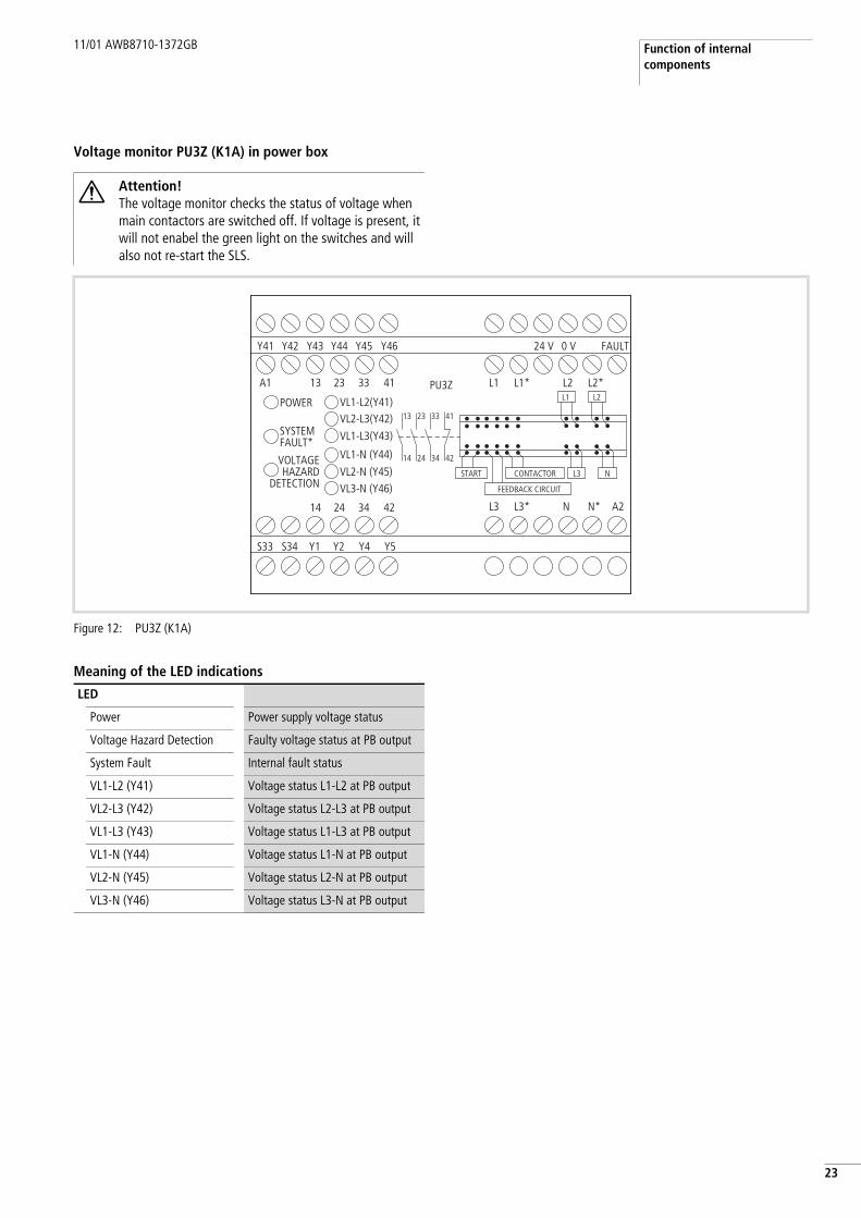
2Voltage monitor PU3Z (K1A) in power box
Meaning of the LED indications
Attention!The voltage monitor checks the status of voltage when main contactors are switched off. If voltage is present, it will not enabel the green light on the switches and will also not re-start the SLS.
Figure 12: PU3Z (K1A)
Y41 Y42 Y43 Y44 Y45 Y46
A1
POWER
SYSTEMFAULT*
VOLTAGEHAZARD
DETECTION
13
VL1-L2(Y41)VL2-L3(Y42)
VL1-L3(Y43)
VL1-N (Y44)
VL2-N (Y45)VL3-N (Y46)
23 33 41 PU3Z
13 23 33 41
14 24 34 42
START CONTACTOR
FEEDBACK CIRCUIT
L3
L1 L2
N
14 24 34 42
L1 L1* L2 L2*
L3 L3* N A2N*
24 V 0 V FAULT
S33 S34 Y1 Y2 Y4 Y5
LED
Power Power supply voltage status
Voltage Hazard Detection Faulty voltage status at PB output
System Fault Internal fault status
VL1-L2 (Y41) Voltage status L1-L2 at PB output
VL2-L3 (Y42) Voltage status L2-L3 at PB output
VL1-L3 (Y43) Voltage status L1-L3 at PB output
VL1-N (Y44) Voltage status L1-N at PB output
VL2-N (Y45) Voltage status L2-N at PB output
VL3-N (Y46) Voltage status L3-N at PB output

Commissioning Instructions 11/01 AWB8710-1372GB
24
Concentrator of inputs (Relays K1A to K4A) in Control Box
The modular safety relay reduces the possibility of failure in safety circuits. It is a concentrator of all inputs. If only one input is disconnected on the relays it will signal a disconnect command to the PB. After all inputs are closed, the disconnect command is removed and the PB is released to switch on the main contactors.
Meaning of the LED indications
The modular safety relays indicate the status of each individual two channel input of the CB. For each input the LED can light up in three different colours (flashing or not) depending on the situation:
• Green Input is “ON“• Flashing green Input is “ON“ during cycle test of
safety relay• Flashing yellow Input is “OFF“• Red (fixed or flashing) Faulty input
The command output from the corresponding module will be “ON“ only if all input LEDs are green. This means that as soon as one of the switches is open, the CB is in the “OFF“ position.
The relationship between the LED’s of the modular relay and the corresponding input connector is indicated in the table below:
Figure 13: PNOZ XM1 (K1A), 3 x PNOZ XE1 (K2A to K4A)
S11 S21 S31 S41 S51 PNOZ XM1
RESETPOWER
RELAIS
DIAG
NO
SEST
ATUS
FAUL
T TYPE
LOCATION
S12/22/32S42/52/62
Y41Y1S34 14 24
13
13 23 33 43 51
14 24 34 44 52MODULNr.
23 33 43 51
34 44 52 A2A1
S22S12 S32
Y2 Y2 Y42 Y30 Y31 Y32 Y35 S42 S52 S62
PNOZ XE1
POWER
S12/22/32
S42/52/62
MODULNr.
S12 S22 S32
S42 S52 S62
PNOZ XE1
POWER
S12/22/32
S42/52/62
MODULNr.
S12 S22 S32
S42 S52 S62
PNOZ XE1
POWER
S12/22/32
S42/52/62
MODULNr.
S12 S22 S32
S42 S52 S62
LED
Power Power supply voltage status of K1A to K4A
RELAIS/RELAY Modular safety relay is energized
TYPE Internal fault
LOCATION A module of the safety relay is defective
S12/22/32 Status indication of 1st input of each module
S42/52/62 Status indication of 2nd input of each module
Monitoring Relay LED Input Connector
PNOZ XM1 (K1A) S12/22/32 X1
S42/52/62 X2
PNOZ XE1 (K2A) S12/22/32 X3
S42/52/62 X4
PNOZ XE1 (K3A) S12/22/32 X5
S42/52/62 X6
PNOZ XE1 (K4A) S12/22/32 X7
S42/52/62 X8

11/01 AWB8710-1372GB Function of internal components
5
2Isolation monitoring (Relay K11A) in the control box
The isolation monitor monitors incorrect connection between both internal power supplies and isolation faults in connection cables to the switches.
Meaning of the LED and button indications
Confirmation relay (K12A) in control box
This safety relay is a confirmation relay for the PU3Z voltage monitor located in the PB. If voltage indicates no voltage present on the switched off main contactors, it closes the safety circuits of this confirmation relay. The safety relay will then supply the green lights of the activated switches with power.
Meaning of the LED indications
Figure 14: P1E-2NK
LED
Power Power supply voltage status
Fault: red Isolation fault in one of the connection cables to switches
Button
TB Test-button for simulating isolation fault
RB Reset button for resetting of an isolation fault
Attention!The function of this button is wired to the blue reset button in the front of the CB.
P1E-2NK
A1 A2 A3 11 21
12 14 22 24 RB RB TB TB
B1 B2EE EE
RB
k O
40TB
POWER FAULT/Störung
Figure 15: PNOZ X2.1
LED
Power Power supply voltage status
CH1 Channel 1 closed
CH2 Channel 2 closed
13 23 24
A1 S33
POWER
CH 1
CH 2
S34
S21 S2214 24
13 23
A2
14 S11 S12
PNOZ X2.1
Commissioning Instructions 11/01 AWB8710-1372GB
26
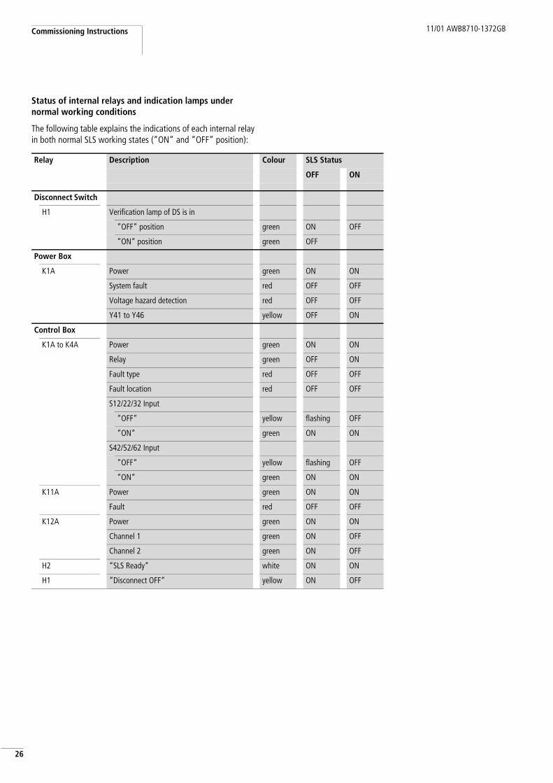
Status of internal relays and indication lamps under normal working conditions
The following table explains the indications of each internal relay in both normal SLS working states (“ON“ and “OFF“ position):
Relay Description Colour SLS Status
OFF ON
Disconnect Switch
H1 Verification lamp of DS is in
“OFF“ position green ON OFF
“ON“ position green OFF
Power Box
K1A Power green ON ON
System fault red OFF OFF
Voltage hazard detection red OFF OFF
Y41 to Y46 yellow OFF ON
Control Box
K1A to K4A Power green ON ON
Relay green OFF ON
Fault type red OFF OFF
Fault location red OFF OFF
S12/22/32 Input
“OFF“ yellow flashing OFF
“ON“ green ON ON
S42/52/62 Input
“OFF“ yellow flashing OFF
“ON“ green ON ON
K11A Power green ON ON
Fault red OFF OFF
K12A Power green ON ON
Channel 1 green ON OFF
Channel 2 green ON OFF
H2 “SLS Ready“ white ON ON
H1 “Disconnect OFF“ yellow ON OFF
11/01 AWB8710-1372GB Status of internal relays and indication lamps under normal working conditions
7
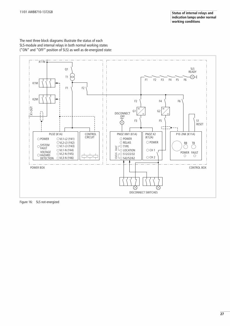
2The next three block diagrams illustrate the status of each SLS-module and internal relays in both normal working states (“ON“ and “OFF“ position of SLS) as well as de-energized state:
Figure 16: SLS not-energized
X1-IN
X1-O
UT
K1M
T1
Q1
F1 F2
K2M
VL1-L2 (Y41)
PU3Z (K1A) PNOZ XM1 (K1A) P1E-2NK (K11A)PNOZ X2 (K12A)
VL2-L3 (Y42)VL1-L3 (Y43)VL1-N (Y44)VL2-N (Y45)VL3-N (Y46)
RB TB
CH 1
G1 G2
F3
h=
F5
F1 F2 F3 F4 F5 F6
F2 F4 F6
CH 2
h=
POWER POWERPOWER
POWER FAULT
RELAISTYPELOCATION
DISCONNECT SWITCHES
DISCONNECTOFF
SLSREADY
S12/22/32
STAT
USFA
ULT
S42/52/62
SYSTEMFAULTVOLTAGEHAZARDDETECTION
POWER BOX CONTROL BOX
S1RESET
CONTROLCIRCUIT

Commissioning Instructions 11/01 AWB8710-1372GB
28
Figure 17: SLS energized in “OFF“ position
X1-IN
X1-O
UT
K1M
T1
Q1
F1 F2
K2M
VL1-L2 (Y41)
PU3Z (K1A) PNOZ XM1 (K1A) P1E-2NK (K11A)PNOZ X2 (K12A)
VL2-L3 (Y42)VL1-L3 (Y43)VL1-N (Y44)VL2-N (Y45)VL3-N (Y46)
RB TB
CH 1
G1 G2
F3
h=
F5
F1 F2 F3 F4 F5 F6
F2 F4 F6
CH 2
h=
POWER POWERPOWER
POWER FAULT
RELAISTYPELOCATION
DISCONNECT SWITCHES
! !Closing delay beforeready for start-up45 sec.
DISCONNECTOFF
SLSREADY
S12/22/32
STAT
USFA
ULT
S42/52/62
SYSTEMFAULTVOLTAGEHAZARDDETECTION
POWER BOX CONTROL BOX
S1RESET
CONTROLCIRCUIT

11/01 AWB8710-1372GB Status of internal relays and indication lamps under normal working conditions
9
2Figure 18: SLS energized in “ON“ position
X1-IN
X1-O
UT
K1M
T1
Q1
F1 F2
K2M
VL1-L2 (Y41)
PU3Z (K1A) PNOZ XM1 (K1A) P1E-2NK (K11A)PNOZ X2 (K12A)
VL2-L3 (Y42)VL1-L3 (Y43)VL1-N (Y44)VL2-N (Y45)VL3-N (Y46)
RB TB
CH 1
G1 G2
F3
h=
F5
F1 F2 F3 F4 F5 F6
F2 F4 F6
CH 2
h=
POWER POWERPOWER
POWER FAULT
RELAISTYPELOCATION
DISCONNECT SWITCHES
DISCONNECTOFF
SLSREADY
S12/22/32
STAT
USFA
ULT
S42/52/62
SYSTEMFAULTVOLTAGEHAZARDDETECTION
POWER BOX CONTROL BOX
S1RESET
CONTROLCIRCUIT

11/01 AWB8710-1372GB
30
11/01 AWB8710-1372GB
1
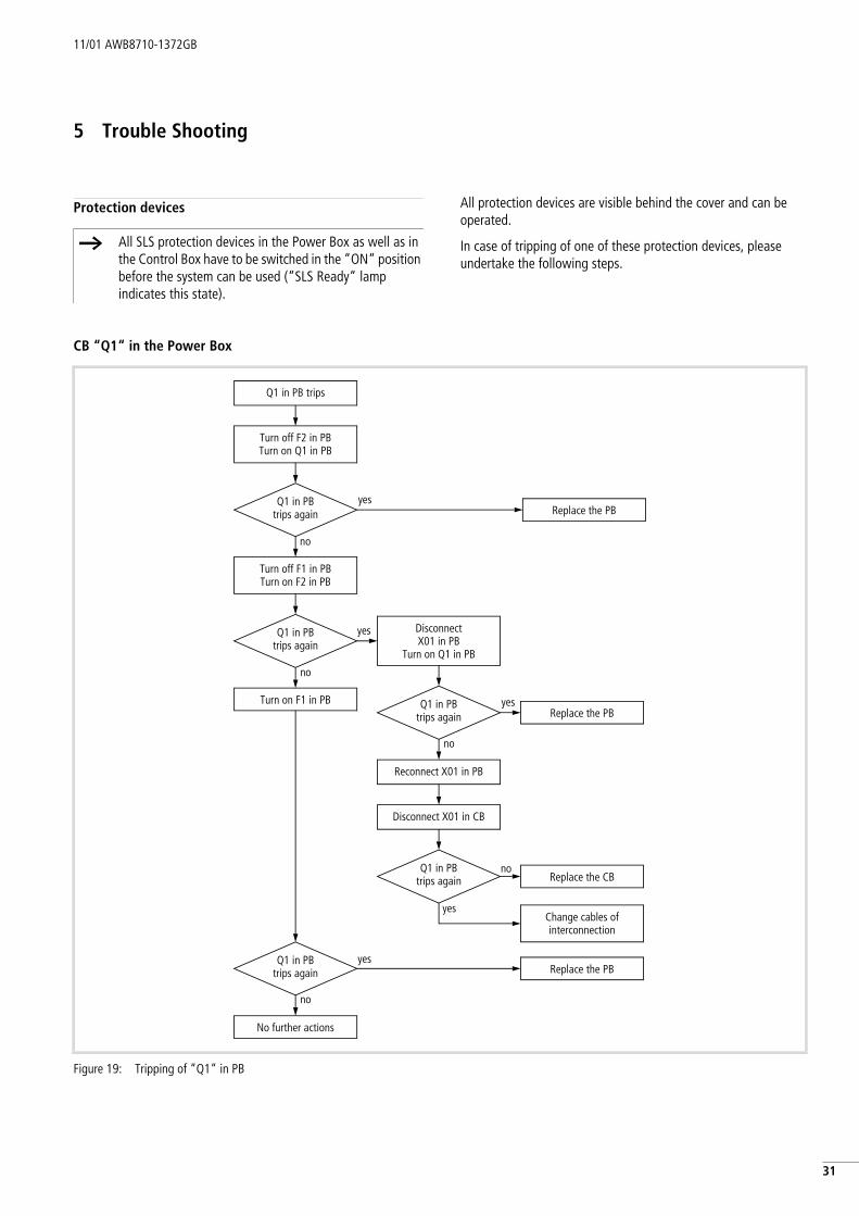
35 Trouble Shooting
Protection devices All protection devices are visible behind the cover and can be operated.
In case of tripping of one of these protection devices, please undertake the following steps.
CB “Q1“ in the Power Box
h All SLS protection devices in the Power Box as well as in the Control Box have to be switched in the “ON“ position before the system can be used (“SLS Ready“ lamp indicates this state).
Figure 19: Tripping of “Q1“ in PB
Q1 in PB trips
Turn on F1 in PB
Q1 in PBtrips again
Turn off F2 in PBTurn on Q1 in PB
Turn off F1 in PBTurn on F2 in PB
Q1 in PBtrips again
yesReplace the PB
DisconnectX01 in PB
Turn on Q1 in PB
yes
yesQ1 in PBtrips again Replace the PB
Reconnect X01 in PB
Disconnect X01 in CB
Q1 in PBtrips again
noReplace the CB
Change cables ofinterconnection
yes
Q1 in PBtrips again
yesReplace the PB
No further actions
no
no
no
no

Trouble Shooting 11/01 AWB8710-1372GB
32
MCB “F1“ in Power Box
MCB “F2“ in Power Box
MCB “F3“ or “F5“ in Control Box
MCB “F2“, “F4“ or “F6“ in Control Box
Figure 20: Tripping of “F1“ in PB
Figure 21: Tripping of “F2“ in PB
F1 in PB trips
F1 in PB trips again
Turn off Q1 in PBTurn on F1 in PBTurn on Q1 in PB
No further actions
yesReplace the PB
no
Turn off Q1 in PBTurn on F2 in PBTurn on Q1 in PB
yesF2 in PB trips again Replace the PB
Turn off Q1 in PBreconnect X01 in PB
Disconnect X01 in CBTurn on Q1 in PB
F2 in PBtrips again
noReplace the CB
Change cables ofinterconnection
yes
F2 in PB trips
Disconnect X01 in PB
no
Figure 22: Tripping of “F3“ or “F5“ in CB
Figure 23: Tripping of “F2“, “F4“ or “F6“ in CB
Reconnect X1 to X8 in CB successively
F3 or F5 in CB trips again
yes Verify corr. interconnection to the
switch or the switch itself
no
No further actions
F3 or F5 in CB trips again
yes
no
Replace the CB
Turn on F3 or F5again in CB
Disconnect X1 to X8 in CB
F3 or F5 in CB trips
F2, F4 or F6in CB trips again
no
Turn on F2 in PB
Replace the CByes
Turn on F2, F4 or F6again in CB
Turn off F2 in PB
No further actions
F2, F4 or F6 in CB trips

11/01 AWB8710-1372GB Voltage monitor in power box
3
3Voltage monitor in power box
“Power“-State
Voltage monitor in voltage hazard statesThe voltage state as well as a voltage hazard will be detected by two types of LED’s.
The first LED types are the six off voltage detecting LED’s named “VL1-L2 (Y41)“, etc., which indicate voltage states >110/64 V AC in both voltage cases (normal working state or hazard) on the SLS output.. The second type of LED is the “Voltage Hazard Detection“ LED, which indicates each voltage hazard >10 V AC. Parallel to this LED, the semiconductor output to PB-X03/5 “Voltage Fault“ also issues a signal.
Figure 24: “Power“ LED
LED “Power” on
LED “Power”
Check Q1 and F1 in PB
yes Normal operating stateNo action
no
See action list fortripping of Q1 or F1
* One or more voltage detection LED‘s (“VL1-L2 (Y41)“, etc.) are illuminated and the corresponding terminal(s) of X1-OUT is (are)supplied with voltage >110 V AC/64 V AC. Also semiconductoroutput at X03/5 “Voltage Fault“ conducts and LED “Voltage Hazard Detection“ is illuminated.
Figure 25: Voltage Hazard >10 V AC
LED‘s on*
Main contactorson
Normal operating stateNo action
yesMain contactorsoff
no
See action list LED“Voltage Hazard Detection”
noyes
yes
LED‘s for voltagedetection
“VL1-L2 (Y41)”, etc.
no

Trouble Shooting 11/01 AWB8710-1372GB
34
* Additionally, semiconductor output at X03/5 “Voltage Fault“ signals also.
Figure 26: Voltage hazard
LED is on* Normal operating stateNo action
no
yes
no
LED “VoltageHazard Detection”
LED‘s ofvoltage detection
are on
no
yes
Measure voltage presence at X1-OUTGet a helper to switch off and on main switch
Terminal(s) is (are) supplied with voltage
>110 V AC/64 V AC and corresp. LED‘s of voltage detection “VL1-L2(Y41)”,
etc. is (are) on
Terminal(s) is (are)supplied with voltage>10 V AC and no LEDof voltage detection
“VL1-L2(Y41)”, etc. is on
yes
Replace the PB
Reverse voltagemust be remedied
Voltageremains/disappears
slowly

11/01 AWB8710-1372GB Voltage monitor in power box
5
3Figure 27: SLS “Voltage hazard detection“ of PU3Z (>10 V AC, but <110 V AC)
X1-IN
X1-O
UT
K1M
T1
Q1
F1 F2
K2M
VL1-L2 (Y41)
PU3Z (K1A) PNOZ XM1 (K1A) P1E-2NK (K11A)PNOZ X2 (K12A)
VL2-L3 (Y42)VL1-L3 (Y43)VL1-N (Y44)VL2-N (Y45)VL3-N (Y46)
RB TB
CH 1
G1 G2
F3
h=
F5
F1 F2 F3 F4 F5 F6
F2 F4 F6
CH 2
h=
POWER POWERPOWER
POWER FAULT
RELAISTYPELOCATION
DISCONNECT SWITCHES
!!
Reve
rse
volta
geor
faul
ty m
ain
cont
acto
rs!
!Vo
ltage
leve
l>
10
V bu
t low
erth
an 1
10 V
DISCONNECTOFF
SLSREADY
S12/22/32
STAT
USFA
ULT
S42/52/62
SYSTEMFAULTVOLTAGEHAZARDDETECTION
POWER BOX CONTROL BOX
S1RESET
CONTROLCIRCUIT
Trouble Shooting 11/01 AWB8710-1372GB
36
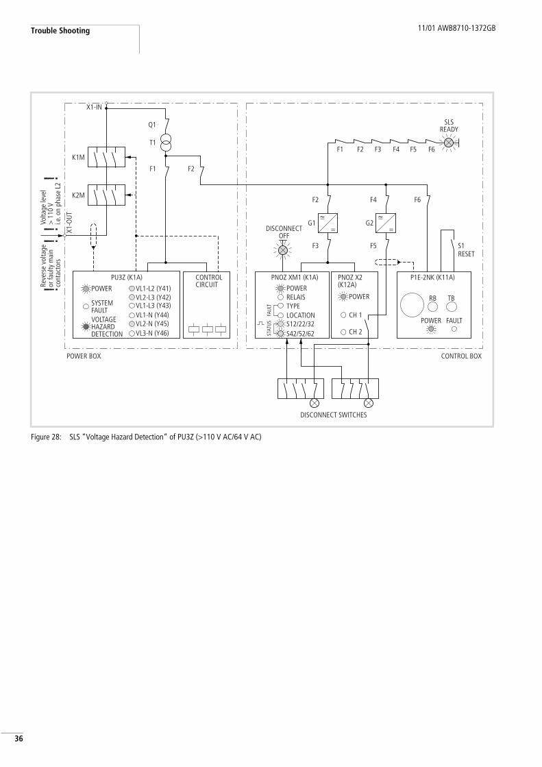
Figure 28: SLS “Voltage Hazard Detection“ of PU3Z (>110 V AC/64 V AC)
X1-IN
X1-O
UT
K1M
T1
Q1
F1 F2
K2M
VL1-L2 (Y41)
PU3Z (K1A) PNOZ XM1 (K1A) P1E-2NK (K11A)PNOZ X2 (K12A)
VL2-L3 (Y42)VL1-L3 (Y43)VL1-N (Y44)VL2-N (Y45)VL3-N (Y46)
RB TB
CH 1
G1 G2
F3
h=
F5
F1 F2 F3 F4 F5 F6
F2 F4 F6
CH 2
h=
POWER POWERPOWER
POWER FAULT
RELAISTYPELOCATION
DISCONNECT SWITCHES
!!
Reve
rse
volta
geor
faul
ty m
ain
cont
acto
rs!
!Vo
ltage
leve
l>
110
Vi.e
. on
phas
e L2
DISCONNECTOFF
SLSREADY
S12/22/32
STAT
USFA
ULT
S42/52/62
SYSTEMFAULTVOLTAGEHAZARDDETECTION
POWER BOX CONTROL BOX
S1RESET
CONTROLCIRCUIT
11/01 AWB8710-1372GB Voltage monitor in power box
7
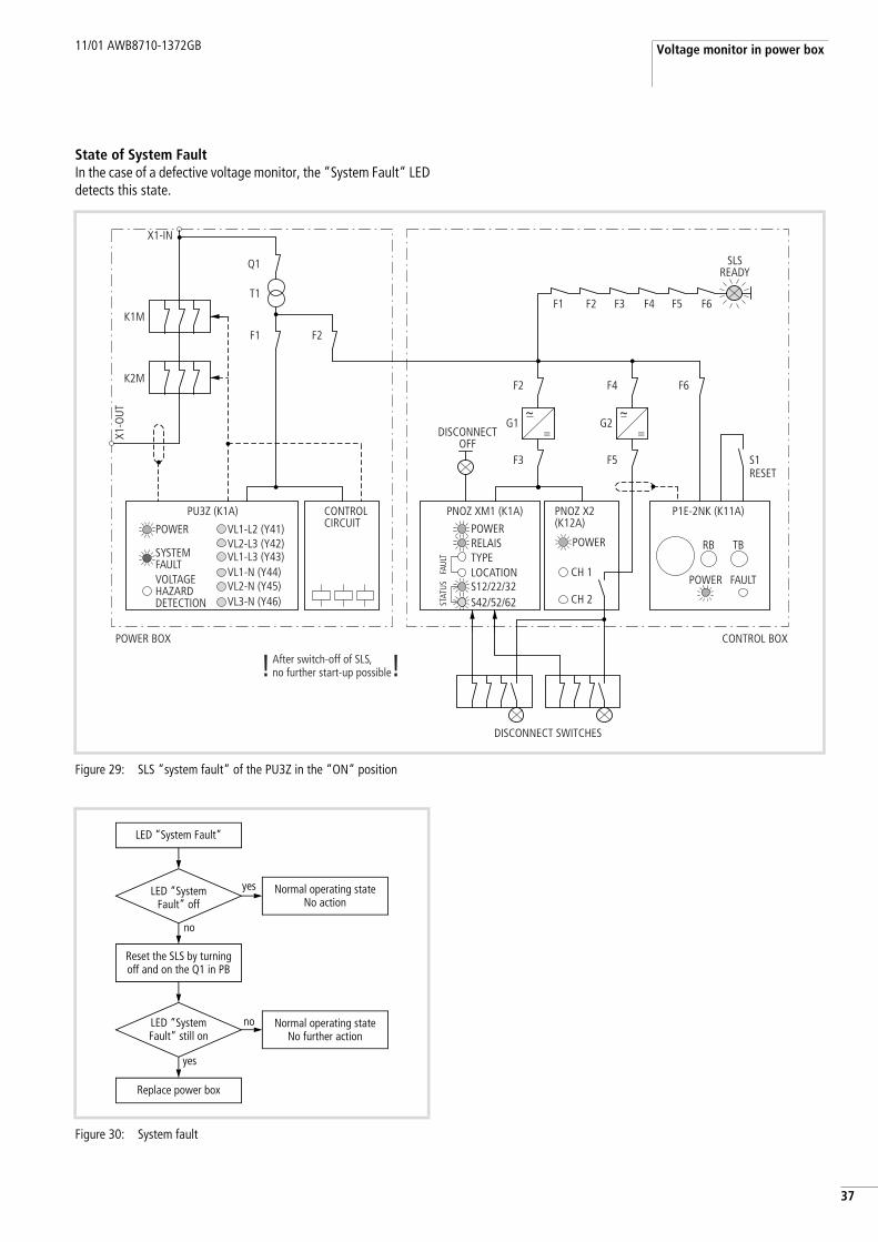
3State of System FaultIn the case of a defective voltage monitor, the “System Fault“ LED detects this state.
Figure 29: SLS “system fault“ of the PU3Z in the “ON“ position
X1-IN
X1-O
UT
K1M
T1
Q1
F1 F2
K2M
VL1-L2 (Y41)
PU3Z (K1A) PNOZ XM1 (K1A) P1E-2NK (K11A)PNOZ X2 (K12A)
VL2-L3 (Y42)VL1-L3 (Y43)VL1-N (Y44)VL2-N (Y45)VL3-N (Y46)
RB TB
CH 1
G1 G2
F3
h=
F5
F1 F2 F3 F4 F5 F6
F2 F4 F6
CH 2
h=
POWER POWERPOWER
POWER FAULT
RELAISTYPELOCATION
DISCONNECT SWITCHES
! !After switch-off of SLS,no further start-up possible
DISCONNECTOFF
SLSREADY
S12/22/32
STAT
USFA
ULT
S42/52/62
SYSTEMFAULTVOLTAGEHAZARDDETECTION
POWER BOX CONTROL BOX
S1RESET
CONTROLCIRCUIT
Figure 30: System fault
LED “System Fault” still on
yes
Normal operating stateNo further action
no
Reset the SLS by turningoff and on the Q1 in PB
Replace power box
LED “SystemFault” off
no
Normal operating stateNo action
yes
LED “System Fault”

Trouble Shooting 11/01 AWB8710-1372GB
38
Concentrated Relay (K1A to K4A) in Control Box
“Power“ state
Operational state
Figure 31: “Power“ LED
LED “Power”on
Check protectionunits in PB & CB
no
no
yes
LED “Power”
Tripping of MCB‘sin SLS
no
yes Normal operating stateNo action
See corresp. action list
yesReplace the CB
yes Inspect cable of interconnection
Replace the PBno
230 V AC at CB-X01 terminal
1 & 2
230 V AC at PB-X01 terminal
1 & 2
Figure 32: “Relay“ LED
LED “Relay”on
no
LED “Relay”
yes Normal operating stateNo action
Replace the CB
yes
no
Replace the CB
Normal operating stateNo action
no
yes
No inputX1-X8 w. disconnect
command
No inputX1-X8 w. disconnect
command

11/01 AWB8710-1372GB Concentrated Relay (K1A to K4A) in Control Box
9
3State of input indications
Figure 33: SLS “S12/22/32“ and/or “S42/52/62“ of PNOZ XM1
X1-IN
X1-O
UT
K1M
T1
Q1
F1 F2
K2M
VL1-L2 (Y41)
PU3Z (K1A) PNOZ XM1 (K1A) P1E-2NK (K11A)PNOZ X2 (K12A)
VL2-L3 (Y42)VL1-L3 (Y43)VL1-N (Y44)VL2-N (Y45)VL3-N (Y46)
RB TB
CH 1
G1 G2
F3
h=
F5
F1 F2 F3 F4 F5 F6
F2 F4 F6
CH 2
h=
POWER POWERPOWER
POWER FAULT
RELAISTYPELOCATION
DISCONNECT SWITCHES
! !Wiring fault or faulty switch
DISCONNECTOFF
SLSREADY
S12/22/32
STAT
USFA
ULT
S42/52/62
SYSTEMFAULTVOLTAGEHAZARDDETECTION
POWER BOX CONTROL BOX
S1RESET
CONTROLCIRCUIT
Trouble Shooting 11/01 AWB8710-1372GB
40
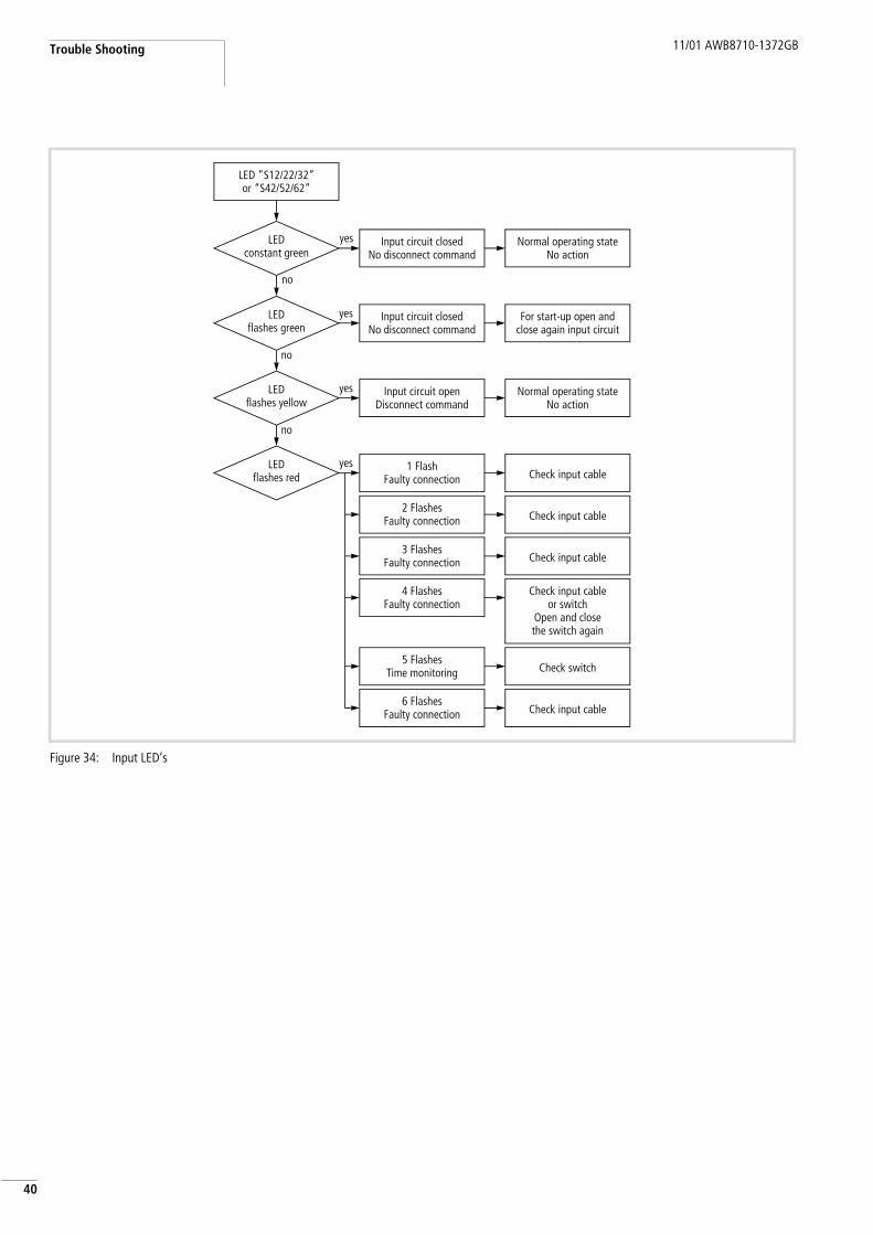
Figure 34: Input LED’s
LED constant green
Input circuit closedNo disconnect command
no
no
yes
LED ”S12/22/32”or “S42/52/62”
LED flashes green
no
LED flashes yellow
LED flashes red
Input circuit closedNo disconnect command
yes Normal operating stateNo action
For start-up open and close again input circuit
Input circuit openDisconnect command
yes Normal operating stateNo action
1 FlashFaulty connection
yesCheck input cable
2 FlashesFaulty connection
3 FlashesFaulty connection
4 FlashesFaulty connection
Check input cable
Check input cable
Check input cableor switch
Open and closethe switch again
5 FlashesTime monitoring
6 FlashesFaulty connection
Check switch
Check input cable

11/01 AWB8710-1372GB Concentrated Relay (K1A to K4A) in Control Box
1
4Fault state
Figure 35: “Type“ fault of PNOZ XM1
X1-IN
X1-O
UT
K1M
T1
Q1
F1 F2
K2M
VL1-L2 (Y41)
PU3Z (K1A) PNOZ XM1 (K1A) P1E-2NK (K11A)PNOZ X2 (K12A)
VL2-L3 (Y42)VL1-L3 (Y43)VL1-N (Y44)VL2-N (Y45)VL3-N (Y46)
RB TB
CH 1
G1 G2
F3
h=
F5
F1 F2 F3 F4 F5 F6
F2 F4 F6
CH 2
h=
POWER POWERPOWER
POWER FAULT
RELAISTYPELOCATION
DISCONNECT SWITCHES
! !Group Fault: “Type” indicationFlashes red, one or two times
DISCONNECTOFF
SLSREADY
S12/22/32
STAT
USFA
ULT
S42/52/62
SYSTEMFAULTVOLTAGEHAZARDDETECTION
POWER BOX CONTROL BOX
S1RESET
CONTROLCIRCUIT

Trouble Shooting 11/01 AWB8710-1372GB
42
Figure 36: “Type“ fault
LED constant red
1 flash
no
yes
LED “Type”
LED flashes red
Switch off and onF3 in CB
yes
Operating voltage too low
3 flashes
Failure of safety relay
Error in safety relaySwitch off and on
one switch
no
LED constant red Replace the CB
No further action
yes
no
2 flashes
LED still flashes 3 times
Switch off and onMCB F2 in PB
LED still flashes 3 times No further action
Replace the CB
no
yes
No further actionno
yes
Check input voltages of SLS
Replace the CB
11/01 AWB8710-1372GB Concentrated Relay (K1A to K4A) in Control Box
3
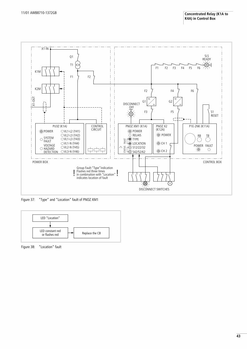
4Figure 37: “Type“ and “Location“ fault of PNOZ XM1
X1-IN
X1-O
UT
K1M
T1
Q1
F1 F2
K2M
VL1-L2 (Y41)
PU3Z (K1A) PNOZ XM1 (K1A) P1E-2NK (K11A)PNOZ X2 (K12A)
VL2-L3 (Y42)VL1-L3 (Y43)VL1-N (Y44)VL2-N (Y45)VL3-N (Y46)
RB TB
CH 1
G1 G2
F3
h=
F5
F1 F2 F3 F4 F5 F6
F2 F4 F6
CH 2
h=
POWER POWERPOWER
POWER FAULT
RELAISTYPELOCATION
DISCONNECT SWITCHES
! !Group Fault:“Type”indicationFlashes red three timesin combination with “Location”indicates location of fault
DISCONNECTOFF
SLSREADY
S12/22/32
STAT
USFA
ULT
S42/52/62
SYSTEMFAULTVOLTAGEHAZARDDETECTION
POWER BOX CONTROL BOX
S1RESET
CONTROLCIRCUIT
Figure 38: “Location“ fault
LED “Location”
LED constant redor flashes red Replace the CB

Trouble Shooting 11/01 AWB8710-1372GB
44
Isolation monitoring relay K11A
“Power“ state
Figure 39: “Power“ LED
LED “Power”on
Check protectionunits in PB & CB
no
no
yes
LED “Power”
Tripping of MCB‘sin SLS
no
yes Normal operating stateNo action
See corresp. action list
yesReplace the CB
yes Inspect cable of interconnection
Replace the PBno
230 V AC at CB-X01 terminal
1 & 2
230 V AC at PB-X01 terminal
1 & 2
11/01 AWB8710-1372GB Isolation monitoring relay K11A
5
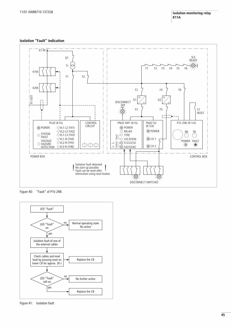
4Isolation “Fault“ indication
Figure 40: “Fault“ of P1E-2NK
X1-IN
X1-O
UT
K1M
T1
Q1
F1 F2
K2M
VL1-L2 (Y41)
PU3Z (K1A) PNOZ XM1 (K1A) P1E-2NK (K11A)PNOZ X2 (K12A)
VL2-L3 (Y42)VL1-L3 (Y43)VL1-N (Y44)VL2-N (Y45)VL3-N (Y46)
RB TB
CH 1
G1 G2
F3
h=
F5
F1 F2 F3 F4 F5 F6
F2 F4 F6
CH 2
h=
POWER POWERPOWER
POWER FAULT
RELAISTYPELOCATION
DISCONNECT SWITCHES
! !Isolation fault detectedNo start-up possibleFault can be reset afterelimination using reset button
DISCONNECTOFF
SLSREADY
S12/22/32
STAT
USFA
ULT
S42/52/62
SYSTEMFAULTVOLTAGEHAZARDDETECTION
POWER BOX CONTROL BOX
S1RESET
CONTROLCIRCUIT
Figure 41: Isolation fault
Normal operating stateNo action
LED “Fault”
LED “Fault”on
noNo further action
Replace the CByes
LED “Fault”still on
Check cables and reset fault by pressing reset on lower CB for approx. 30 s
Isolation fault of one of the external cables
yes
no
Replace the CB

Trouble Shooting 11/01 AWB8710-1372GB
46
Confirmation relay K12A of voltage monitor PU3Z
“Power“ state
Figure 42: “Power“ LED
LED “Power”on
Check protectionunits in PB & CB
no
no
yes
LED “Power”
Tripping of MCB‘sin SLS
no
yes Normal operating stateNo action
See corresp. action list
yesReplace the CB
yes Inspect cable of interconnection
Replace the PBno
230 V AC at CB-X01 terminal
1 & 2
230 V AC at PB-X01 terminal
1 & 2

11/01 AWB8710-1372GB Confirmation relay K12A of voltage monitor PU3Z
7
4Channel state indication
Figure 43: SLS “CH1“ and/or “CH2“ of PNOZ X2.1
X1-IN
X1-O
UT
K1M
T1
Q1
F1 F2
K2M
VL1-L2 (Y41)
PU3Z (K1A) PNOZ XM1 (K1A) P1E-2NK (K11A)PNOZ X2 (K12A)
VL2-L3 (Y42)VL1-L3 (Y43)VL1-N (Y44)VL2-N (Y45)VL3-N (Y46)
RB TB
CH 1
G1 G2
F3
h=
F5
F1 F2 F3 F4 F5 F6
F2 F4 F6
CH 2
h=
POWER POWERPOWER
POWER FAULT
RELAISTYPELOCATION
DISCONNECT SWITCHES
! !No reaction of K12A,although PU3Z is active=> no green light at switches
DISCONNECTOFF
SLSREADY
S12/22/32
STAT
USFA
ULT
S42/52/62
SYSTEMFAULTVOLTAGEHAZARDDETECTION
POWER BOX CONTROL BOX
S1RESET
CONTROLCIRCUIT
Trouble Shooting 11/01 AWB8710-1372GB
48
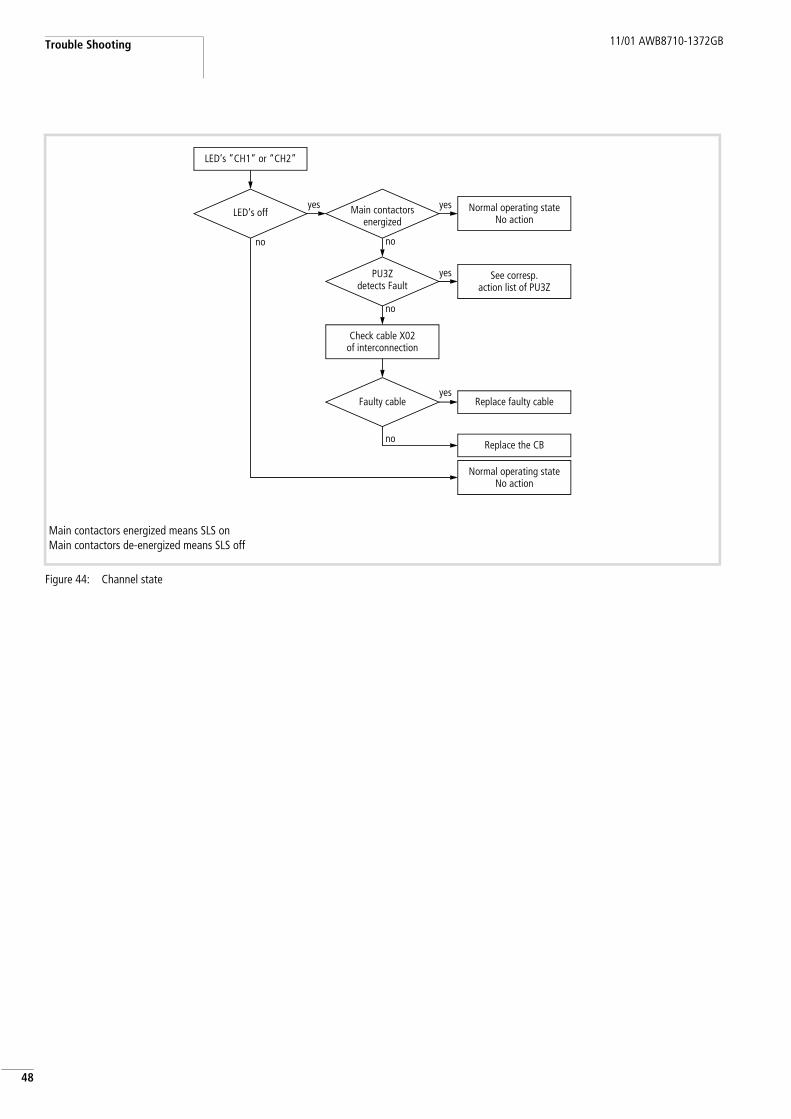
Main contactors energized means SLS onMain contactors de-energized means SLS off
Figure 44: Channel state
LED‘s off
no
LED‘s ”CH1” or “CH2”
yes Main contactorsenergized
Normal operating stateNo action
Check cable X02of interconnection
yes
no
Replace faulty cableyes
Faulty cable
PU3Zdetects Fault
no
Replace the CB
Normal operating stateNo action
See corresp.action list of PU3Z
yes
no
11/01 AWB8710-1372GB Indication lamps on the control box
9
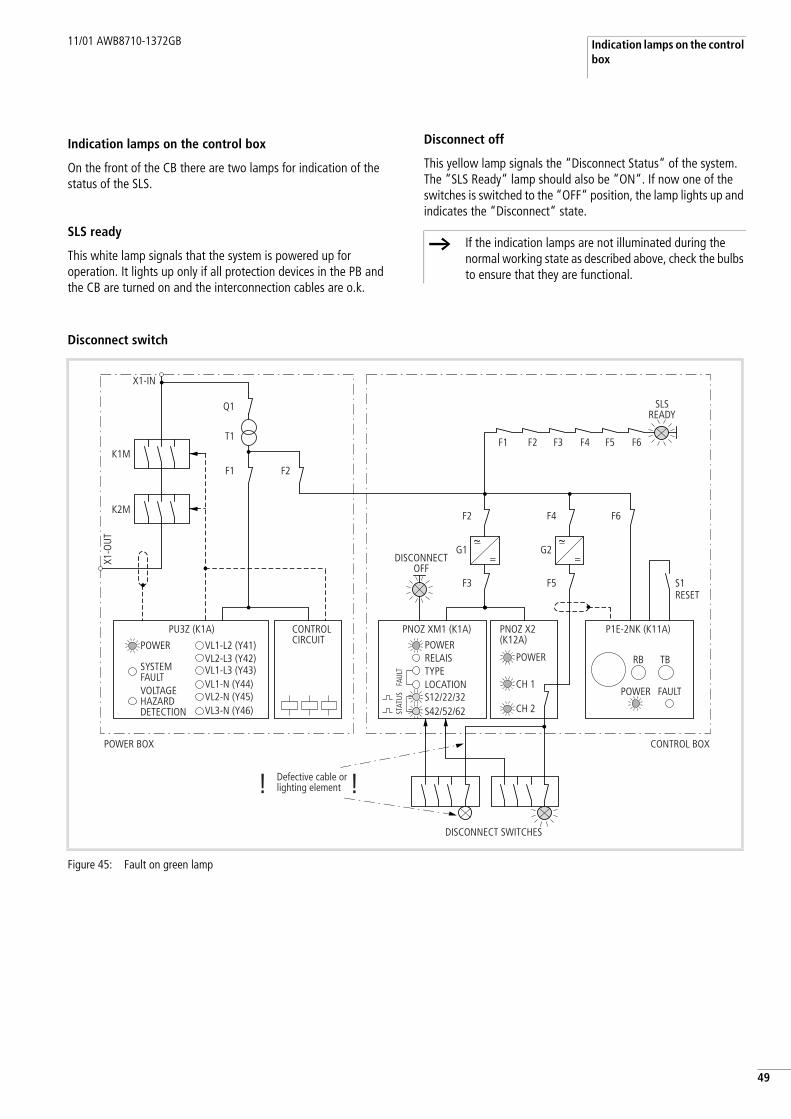
4Indication lamps on the control box
On the front of the CB there are two lamps for indication of the status of the SLS.
SLS ready
This white lamp signals that the system is powered up for operation. It lights up only if all protection devices in the PB and the CB are turned on and the interconnection cables are o.k.
Disconnect off
This yellow lamp signals the “Disconnect Status“ of the system. The “SLS Ready“ lamp should also be “ON“. If now one of the switches is switched to the “OFF“ position, the lamp lights up and indicates the “Disconnect“ state.
Disconnect switch
h If the indication lamps are not illuminated during the normal working state as described above, check the bulbs to ensure that they are functional.
Figure 45: Fault on green lamp
X1-IN
X1-O
UT
K1M
T1
Q1
F1 F2
K2M
VL1-L2 (Y41)
PU3Z (K1A) PNOZ XM1 (K1A) P1E-2NK (K11A)PNOZ X2 (K12A)
VL2-L3 (Y42)VL1-L3 (Y43)VL1-N (Y44)VL2-N (Y45)VL3-N (Y46)
RB TB
CH 1
G1 G2
F3
h=
F5
F1 F2 F3 F4 F5 F6
F2 F4 F6
CH 2
h=
POWER POWERPOWER
POWER FAULT
RELAISTYPELOCATION
DISCONNECT SWITCHES
! !Defective cable orlighting element
DISCONNECTOFF
SLSREADY
S12/22/32
STAT
USFA
ULT
S42/52/62
SYSTEMFAULTVOLTAGEHAZARDDETECTION
POWER BOX CONTROL BOX
S1RESET
CONTROLCIRCUIT

Trouble Shooting 11/01 AWB8710-1372GB
50
Figure 46: Fault on green lamp
Greenlamp on
no
Green indication light
yes Switchis in Off-position
Normal operating stateNo action
State not possible
yes
no
Check CB-X1 to X8terminal “5” & “6”
for 24 V DC
Check cable
Check lightingelement in switch
no
yes
Normal operating stateNo action
yes
no
Switchis in On-position
24 V DCis present
Check CB and PB to corresponding description
no24 V DCis present
Check terminal“11” & “X2”
for voltage 24 V DC
yes
11/01 AWB8710-1372GB
1
56 General Information for the Replacement of Sealed Units
Each SLS module is sealed with Moeller seals, when it is delivered. The interfaces for customer connection as well as the enclosures of the disconnect switches are assembled in an unsealed unit. Moeller recommends, that authorized persons should seal all enclosures after installation and start-up of the SLS. This ensures the integrity of the total SLS.
The following interfaces are however accessible to the customer and not sealed by Moeller:
• Main power terminals of PB• Interconnection connectors between PB and CB (X01, X02)• Input connectors of CB (X1 to X8)• PLC-Interface terminals of PB and CB (X03)
After delivery, a visual inspection of the modules for external damage has to be carried out by the customer. Moeller must be informed immediately if visible damage to enclosure, devices, housings or a damaged/broken seal is found. Moeller will exchange damaged modules as soon as possible. Only modules in perfect condition may be installed and used in an SLS.
Please do not open the sealed units for the SLS-modules, because Moeller cannot provide a guarantee or warranty once these modules have been opened.
If the system develops a fault in a module, Moeller cannot provide a warranty for this module if the seals have been broken. The warranty expires at the end of the warranty period, or immediately if the seals are broken by unauthorized personnel.
The disconnect switches should be sealed by persons authorized by the customer as soon as the cables have been connected.
Module types in CI-enclosure or sheet steel enclosures
If the SLS-Unit malfunctions, the entire faulty module must be replaced as follows:
• Turn off and padlock the mains supply switch to the SLS System.• Open the seals only on the customer connection enclosures and
disconnect the power cables (PB only) and all control cable connectors (X01, X02, X1 to X16 and X03).
• Remove the defective SLS-module and exchange it with an SLS-module of the same type.
• Reconnect all power and control cables to the correct terminals.• During the warranty period, send faulty SLS-modules to
Moeller, where they will be tested and repaired. They will be returned free of charge. The repair will be subject to a charge after the warranty period or if the seal is broken.
Module types as fully withdrawable units of the MODAN6000MCC
These SLS-modules (PB types only) are supplied integrated into an MCC-panel type MODAN6000, or separately as a spare part for this MCC-panel. In any case this unit is also sealed.
• If the SLS-module in a withdrawable unit is integrated in an MCC, the unit is sealed so that it cannot be removed from the MCC without breaking the wire seal.
• If the SLS-module in a withdrawable unit is supplied as a spare part, the packing is sealed in such a way that the unit cannot be taken out of the packing without breaking the wire seal.
Faulty SLS-modules in withdrawable units may only be exchanged by authorized persons. The exchange procedure is described in the following steps:
• Turn off the mains supply switch of the SLS system. It can be integrated directly into the same withdrawable unit or next to the PB in a second unit.
• The seal wire has to be broken and the faulty SLS-module has to be withdrawn from the MCC-panel.
• The spare part module received has to be checked for shipping damage. If the packing is not damaged, the seal-wire of the packing can be broken and the spare part module can be unpacked.
• The spare unit can now be installed in the MCC-panel. Exchange the faulty SLS-module only with the same SLS-module type or better.
• After the SLS is operational with this exchanged unit, the new SLS-module has to be sealed with two seal wires in the installed position by an authorized person.
• A protocol with the following data is required for:– internal documentation on-site– documentation which is to be sent to Moeller during the
warranty period.The following details are required:– Name of project– Factory number of unit(s)– Module type of faulty SLS-module– Module type of exchanged spare part unit– Date– Signature of maintenance personnel on-site.
• During the warranty period, please return the faulty SLS-unit packed in the packing of the spare part unit to Moeller, where it will be repaired and tested. It will then be returned after repair. Repairs after the warranty period has expired and/or the seals have been broken, will be subject to a charge.
• If support is required, please contact your local Moeller representative.
Warning!Do not open the sealed units of the SLS-modules. Opening and working on any of the sealed devices will free Moeller from any accident liability or warranty claims.

11/01 AWB8710-1372GB
52

11/01 AWB8710-1372GB
3
5Appendix
Technical Data
SLS, Cables/Interconnection
General
Standards and regulations considered for the SLS design with CI enclosure IEC/EN 60204-1IEC/EN 60439-1EN 954-1EN 1037UL 508A73/23/EC Low Voltage Directive89/336/EC EMC Directive98/37/EC Machinery Directive
Electrical Characteristics
Grid type TN-S-Network
Rated operation voltage 400 V, 3-ph or 480 V, 3-ph1)
Voltage fluctuations +/– 10 %
Frequency 50/60 Hz
Current Ic a Power Box specification
Motor rating for SLS
in CI enclosure 5.5 to 75 kW, AC3, 380/440 V7.5 to 100 HP; 480 V
in sheet steel enclosure 75 to 250 kW, AC3, 380/440 V100 to 300 HP; 480 V
Mechanical Characteristics
Expected life of the SLS 106 cycles (ON-OFF)
Cables/Interconnections
All connections between Power-, Control- and Marshalling Box should be made with min. 1.5 mm2 (AWG 16) wires, max. 2.5 mm2 (AWG 13) wires possible.
The connections to the Disconnect Switches have to be made with 0.75 mm2 (AWG 18) to max. 1.5 mm2 (AWG 14) wires.
Shielded cables are not necessary for the correct operation of the Safety Lockout System.
1) Control Voltage 400 or 480 V has to be chosen via link on terminal block XT.

Appendix 11/01 AWB8710-1372GB
54
SLS in Totally Insulated CI Enclosure
General
Standards IEC/EN 60204-1IEC/EN 60439-1UL 508A73/23/EC Low Voltage Directive
Climatic test Damp heat, constant, to IEC 60068 Part 2 – 3.Damp heat, cyclic, to IEC 60068 Part 2 – 30.
Chemical environment According to paragraph 6.1.2. of the IEC/EN 60439-1 standard.
EMC According to EN 50081-2 and EN 55011. Interference class “A”.
Ambient temperature min./max. According to IEC/EN 60439-1 standard.
Average over a period of 24 hMaximum:Minimum:
+35 °C+40 °C–5 °C
Altitude Max. 2000 m above sea level
Relative humidity According to paragraph 6.1.2.1. of the IEC/EN 60439-1 standard.
Installation conditions Indoor installation acc. IEC 60439-1.Protected outdoor installation acc. IEC 60364.
Degree of protection IP55 to IEC 60529
Clearances and creepage distances IEC 60664
Overvoltage category III
Pollution degree 3
Material Thermoplastic
Base Glass-fibre reinforced polycarbonate
Cover Polycarbonate not reinforced
Flammability characteristics
Glow wire test to IEC 60695-1-2A 960 °C
UL: Base UL 94 V1
Cover UK 94 V2
Halogen free Yes (enclosure base and cover)
11/01 AWB8710-1372GB Technical Data
5
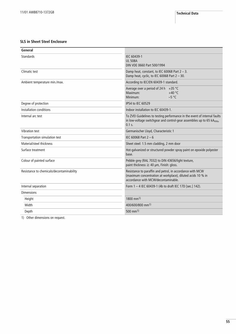
5SLS in Sheet Steel Enclosure
General
Standards IEC 60439-1UL 508ADIN VDE 0660 Part 500/1994
Climatic test Damp heat, constant, to IEC 60068 Part 2 – 3.Damp heat, cyclic, to IEC 60068 Part 2 – 30.
Ambient temperature min./max. According to IEC/EN 60439-1 standard.
Average over a period of 24 hMaximum:Minimum:
+35 °C+40 °C–5 °C
Degree of protection IP54 to IEC 60529
Installation conditions Indoor installation to IEC 60439-1.
Internal arc test To ZVEI Guidelines to testing performance in the event of internal faults in low-voltage switchgear and control-gear assemblies up to 65 kArms, 0.1 s.
Vibration test Germanischer Lloyd, Characteristic 1
Transportation simulation test IEC 60068 Part 2 – 6
Material/steel thickness Sheet steel: 1.5 mm cladding, 2 mm door
Surface treatment Hot-galvanized or structured powder spray paint on epoxide polyester base.
Colour of painted surface Pebble grey (RAL 7032) to DIN 43656/light texture, paint thickness f 40 µm, Finish: gloss.
Resistance to chemicals/decontaminability Resistance to paraffin and petrol, in accordance with MCW (maximum concentration at workplace), diluted acids 10 % in accordance with MCW/decontaminable.
Internal separation Form 1 – 4 IEC 60439-1 (4b to draft IEC 17D [sec.] 142).
Dimensions
Height 1800 mm1)
Width 400/600/800 mm1)
Depth 500 mm1)
1) Other dimensions on request.

Appendix 11/01 AWB8710-1372GB
56
SLS in Fully Withdrawable MODAN6000 Unit
In addition to “General” data of SLS System in sheet steel enclosure please find below the “Electrical Data” of Motor Control Centre MODAN6000. In this case the Power Box is built into a fully withdrawable unit of the Moeller system MODAN6000.
MDM Motor Control Centre and Power Distribution Section
Technical data identical to those listed under “Electrical Data” MODAN6000; the following table shows only the discrepancies.
Electrical Data
Rated insulation voltage Ui 1000 V AC/1200 V DC to DIN VDE600 V DC to UL and BS
Insulation group lll/3 to DIN VDE 0110/1.89BS 162 Table 4 and UL 508 Table 18.1
Rated operational voltage Ue 690 V to IEC 60038
Rated frequency 40 to 60 Hz
Motor rating for SLS System 5.5 to 200 kW, AC3, 380/440 V7.5 to 250 HP; 480 V
General
Degree of protection IP30 to IP32; IP40 to IP42, IP54
Dimensions
Height 2200 mm
Width 1000/1200 mm
Depth 600/800/1000 mm
Electrical characteristics for standard installed equipment
Rated currents
Power outgoers Ie Up to 630 A (IEC 439)
Motor starters 400 V, AC-23
Direct-on-line starters Up to 250 kW
Motor starters 480 V, in HP Up to 300 HP
Electrical characteristics for distribution busbars
Rated currents Ie 1 x 1000 A
Rated prospective short-circuit withstand current Isc" 65 kArms 100 ms
Rated short-time withstand current Icw 65 kA 1 s
Rated peak withstand current Ipk 143 kA
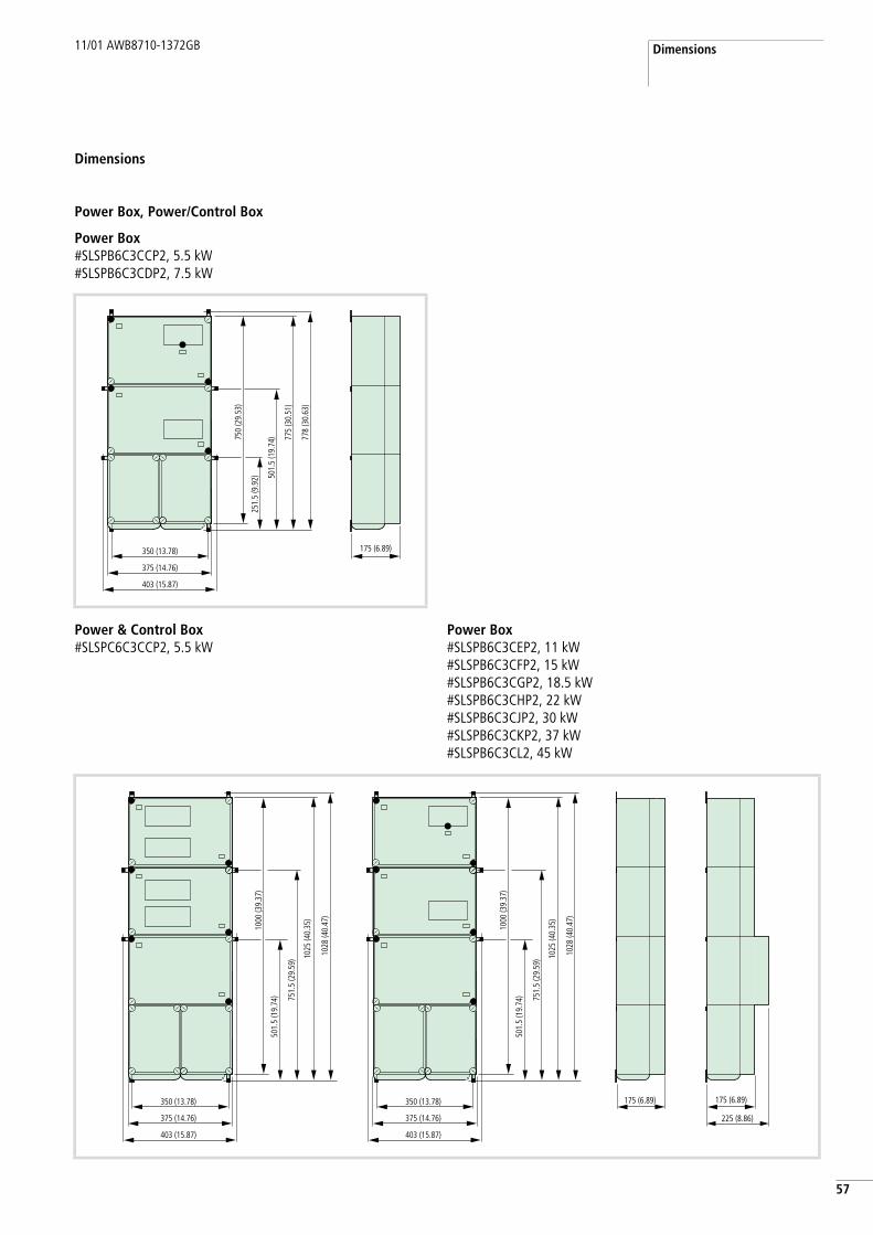
11/01 AWB8710-1372GB Dimensions
7
5Dimensions
Power Box, Power/Control Box
Power Box#SLSPB6C3CCP2, 5.5 kW#SLSPB6C3CDP2, 7.5 kW
175 (6.89)350 (13.78)
251.
5 (9
.92)
750
(29.
53)
501.
5 (1
9.74
) 775
(30.
51)
778
(30.
63)
375 (14.76)
403 (15.87)
Power & Control Box#SLSPC6C3CCP2, 5.5 kW
Power Box#SLSPB6C3CEP2, 11 kW#SLSPB6C3CFP2, 15 kW#SLSPB6C3CGP2, 18.5 kW#SLSPB6C3CHP2, 22 kW#SLSPB6C3CJP2, 30 kW#SLSPB6C3CKP2, 37 kW#SLSPB6C3CL2, 45 kW
175 (6.89) 175 (6.89)
225 (8.86)
350 (13.78)
1000
(39.
37)
501.
5 (1
9.74
) 751.
5 (2
9.59
) 1025
(40.
35)
1028
(40.
47)
375 (14.76)
403 (15.87)
350 (13.78)
1000
(39.
37)
501.
5 (1
9.74
) 751.
5 (2
9.59
) 1025
(40.
35)
1028
(40.
47)
375 (14.76)
403 (15.87)

Appendix 11/01 AWB8710-1372GB
58
Power Box#SLSPB6C3CMP2, 55 kW#SLSPB6C3CNP2, 75 kW
Power Box#SLSPB6C3CNS1, 75 kW
175 (6.89)
225 (8.86)
175 (6.89)
275 (10.83)
350 (13.78)
1125
(44.
29)
276.
5 (1
0.88
)
651.
5 (2
5.64
)
1150
(45.
28)
1153
(45.
39)
375 (14.76)
403 (15.87)
175 (6.89)
275 (10.83)
350 (13.78)
1125
(44.
29)
501.
5 (1
9.74
)
876.
5 (3
4.51
)
1153
(45.
39)
1175
(46.
26)
375 (14.76)
403 (15.87)
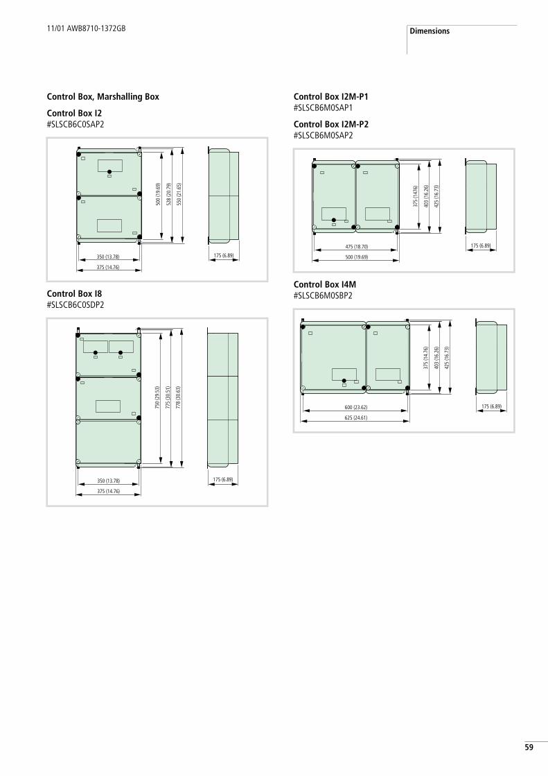
11/01 AWB8710-1372GB Dimensions
9
5Control Box, Marshalling Box
Control Box I2#SLSCB6C0SAP2
Control Box I8#SLSCB6C0SDP2
Control Box I2M-P1#SLSCB6M0SAP1
Control Box I2M-P2#SLSCB6M0SAP2
Control Box I4M#SLSCB6M0SBP2
175 (6.89)350 (13.78)
500
(19.
69)
528
(20.
79)
550
(21.
65)
375 (14.76)
175 (6.89)350 (13.78)
750
(29.
53)
775
(30.
51)
778
(30.
63)
375 (14.76)
175 (6.89)475 (18.70)
375
(147
6)
403
(16.
26)
425
(16.
73)
500 (19.69)
175 (6.89)600 (23.62)
375
(14.
76)
403
(16.
26)
425
(16.
73)
625 (24.61)

Appendix 11/01 AWB8710-1372GB
60
Marshalling Box I8#SLSMB6C0SDP2
Marshalling Box I16#SLSMB6C0SHP2
Marshalling Box I16M#SLSMB6M0SHP2
Disconnect Switch, Emergency-Stop Button
Disconnect Switch#SLSDS00000P1#SLSDS00001P2
Emergency-Stop Button, completefor surface mountingM22-PV/KC02/IY
Cable entries: 2 x M16, 3 x M20, 2 x M25
175 (6.89)350 (13.78)
500
(19.
69)
525
(20.
67)
528
(20.
79)
375 (14.76)
175 (6.89)350 (13.78)
625
(24.
61)
650
(25.
59)
653
(25.
71)
375 (14.76)
L-GM4
80 (3.15)
120
(4.7
2)33
.5 (1
.32)
75 (2.95) 35 (1.38)
127
(5.0
0)
137
(5.3
9) I
OFFo
ON
oOFF
58.5
66.5
M20/M25 M16
17.8
56
44
80
72
47.9
M4

11/01 AWB8710-1372GB Declaration of Conformity
1
6Declaration of Conformity

Appendix 11/01 AWB8710-1372GB
62

11/01 AWB8710-1372GB
3
6Index
A Allowed maximum cable lengths . . . . . . . . . . . . . . . . . 13
C Category 3 . . . . . . . . . . . . . . . . . . . . . . . . . . . . . . . . . . 11Category 4 . . . . . . . . . . . . . . . . . . . . . . . . . . . . . . . 5, 6, 7CH1 . . . . . . . . . . . . . . . . . . . . . . . . . . . . . . . . . . . . . . . 47CH2 . . . . . . . . . . . . . . . . . . . . . . . . . . . . . . . . . . . . . . . 47Channel state . . . . . . . . . . . . . . . . . . . . . . . . . . . . . . . 48Channel state indication . . . . . . . . . . . . . . . . . . . . . . . 47Common Voltage . . . . . . . . . . . . . . . . . . . . . . . . . . 18, 20Confirmation relay . . . . . . . . . . . . . . . . . . . . . . . . . . . . 25Confirmation relay K12A of voltage monitor PU3Z . . . . 46Control Box block diagram . . . . . . . . . . . . . . . . . . . . . . 17Control Box Status . . . . . . . . . . . . . . . . . . . . . . . . . . . . 18
D Dimensions . . . . . . . . . . . . . . . . . . . . . . . . . . . . . . . . . 57Disconnect command . . . . . . . . . . . . . . . . . . . . . . . . . . 11Disconnect Command Confirmation . . . . . . . . . . . . 18, 20Distances . . . . . . . . . . . . . . . . . . . . . . . . . . . . . . . . . . . 13
E Electrical protection of the SLS . . . . . . . . . . . . . . . . . . . . 7
F Fault . . . . . . . . . . . . . . . . . . . . . . . . . . . . . . . . . . . . . . 45Fault of Control Box . . . . . . . . . . . . . . . . . . . . . . . . . . . 18Fault of Marshalling Box . . . . . . . . . . . . . . . . . . . . . . . 20Fault on green lamp . . . . . . . . . . . . . . . . . . . . . . . . 49, 50Faulty SLS-modules . . . . . . . . . . . . . . . . . . . . . . . . . . . 51
I Input indications . . . . . . . . . . . . . . . . . . . . . . . . . . . . . 39Input LED’s . . . . . . . . . . . . . . . . . . . . . . . . . . . . . . . . . 40Intended usage and limitations . . . . . . . . . . . . . . . . . . . 7Interconnections for CB . . . . . . . . . . . . . . . . . . . . . . . . 18Interconnections for MB . . . . . . . . . . . . . . . . . . . . . . . . 20Interconnections for PB . . . . . . . . . . . . . . . . . . . . . . . . 16Isolation “Fault“ indication . . . . . . . . . . . . . . . . . . . . . 45Isolation fault . . . . . . . . . . . . . . . . . . . . . . . . . . . . . . . 45Isolation monitor . . . . . . . . . . . . . . . . . . . . . . . . . . . . . 25Isolation monitoring . . . . . . . . . . . . . . . . . . . . . . . . . . 25Isolation monitoring relay K11A . . . . . . . . . . . . . . . . . . 44Isolation Monitoring Status . . . . . . . . . . . . . . . . . . . . . 18
L LED indications . . . . . . . . . . . . . . . . . . . . . . . . . . . 23, 24Location . . . . . . . . . . . . . . . . . . . . . . . . . . . . . . . . . . . 43Location fault . . . . . . . . . . . . . . . . . . . . . . . . . . . . . . . 43
M Main Contactors . . . . . . . . . . . . . . . . . . . . . . . . . . . . . 16Marshalling box . . . . . . . . . . . . . . . . . . . . . . . . . . . . . . 19Marshalling Box block diagram . . . . . . . . . . . . . . . . . . 19Marshalling Box Status . . . . . . . . . . . . . . . . . . . . . . . . 20Modular safety relay . . . . . . . . . . . . . . . . . . . . . . . . . . 24Module description . . . . . . . . . . . . . . . . . . . . . . . . . . . 10Monitoring relay . . . . . . . . . . . . . . . . . . . . . . . . . . . . . 24
N No Voltage Hazard . . . . . . . . . . . . . . . . . . . . . . . . . . . . 16
O Operating voltage . . . . . . . . . . . . . . . . . . . . . . . . . . . . 21Operational state . . . . . . . . . . . . . . . . . . . . . . . . . . . . . 38Optional modules . . . . . . . . . . . . . . . . . . . . . . . . . . . . . 11
P Padlock . . . . . . . . . . . . . . . . . . . . . . . . . . . . . . . . . 22, 51Power Box block diagram . . . . . . . . . . . . . . . . . . . . . . . 15Power state . . . . . . . . . . . . . . . . . . . . . . . . . . . . . . . . . 38Protection devices . . . . . . . . . . . . . . . . . . . . . . . . . . . . 31
R Restart the SLS . . . . . . . . . . . . . . . . . . . . . . . . . . . . . . . 22Risk assessment . . . . . . . . . . . . . . . . . . . . . . . . . . . . . . . 6
S S12/22/32 . . . . . . . . . . . . . . . . . . . . . . . . . . . . . . . . . . 39S42/52/62 . . . . . . . . . . . . . . . . . . . . . . . . . . . . . . . . . . 39Sealed units . . . . . . . . . . . . . . . . . . . . . . . . . . . . . . . . . 51Site of installation . . . . . . . . . . . . . . . . . . . . . . . . . . . . 13SLS energized in “OFF“ position . . . . . . . . . . . . . . . . . 28SLS energized in “ON“ position . . . . . . . . . . . . . . . . . . 29SLS not-energized . . . . . . . . . . . . . . . . . . . . . . . . . . . . 27SLS overview . . . . . . . . . . . . . . . . . . . . . . . . . . . . . . . . . 8Start up of SLS . . . . . . . . . . . . . . . . . . . . . . . . . . . . . . . 21Start/Stop commands . . . . . . . . . . . . . . . . . . . . . . . . . . . 7Start-up flow diagram . . . . . . . . . . . . . . . . . . . . . . . . . 21Status Control Box . . . . . . . . . . . . . . . . . . . . . . . . . . . . 18Status Marshalling Box . . . . . . . . . . . . . . . . . . . . . . . . 20Stop command . . . . . . . . . . . . . . . . . . . . . . . . . . . . . . . 22Supply of Semiconductor Outputs . . . . . . . . . . . 16, 18, 20System Fault . . . . . . . . . . . . . . . . . . . . . . . . . . . . . . . . 37System fault . . . . . . . . . . . . . . . . . . . . . . . . . . . . . . . . . 37System overview . . . . . . . . . . . . . . . . . . . . . . . . . . . . 8, 9

Index 11/01 AWB8710-1372GB
64
T Technical Data . . . . . . . . . . . . . . . . . . . . . . . . . . . . . . .53Terminal block XT . . . . . . . . . . . . . . . . . . . . . . . . . .13, 21Time Delay Module . . . . . . . . . . . . . . . . . . . . . . . . . . . .11Tripping of “F1“ in PB . . . . . . . . . . . . . . . . . . . . . . . . .32Tripping of “F2“ in PB . . . . . . . . . . . . . . . . . . . . . . . . .32Tripping of “F2“, “F4“ or “F6“ in CB . . . . . . . . . . . . . .32Tripping of “F3“ or “F5“ in CB . . . . . . . . . . . . . . . . . . .32Tripping of “Q1“ in PB . . . . . . . . . . . . . . . . . . . . . . . . .31Type . . . . . . . . . . . . . . . . . . . . . . . . . . . . . . . . . . . .41, 43Type fault . . . . . . . . . . . . . . . . . . . . . . . . . . . . . . . . . . .42
V Voltage Fault . . . . . . . . . . . . . . . . . . . . . . . . . . . . . . . .16Voltage hazard . . . . . . . . . . . . . . . . . . . . . . . . . . . .33, 34Voltage Hazard >10 V AC . . . . . . . . . . . . . . . . . . . . . . .33Voltage Hazard Detection . . . . . . . . . . . . . . . . .33, 35, 36Voltage monitor . . . . . . . . . . . . . . . . . . . . . . . . . . . . . .23Voltage monitor in power box . . . . . . . . . . . . . . . . . . . .33Voltage monitor PU3Z . . . . . . . . . . . . . . . . . . . . . . . . .23
W Warranty . . . . . . . . . . . . . . . . . . . . . . . . . . . . . . . . . . .51
Z Zero-energy . . . . . . . . . . . . . . . . . . . . . . . . . . . . . . . . .22Zero-energy status . . . . . . . . . . . . . . . . . . . . . . . . .10, 11