Hardigg M9 TestRpt 20090225 - PartA CoverAbstract&Signature
30
Transcript of Hardigg M9 TestRpt 20090225 - PartA CoverAbstract&Signature


AFPTEF Report No. 09-R-01 Hardigg M9 Case AFPTEF Project No. 09-P-103
ii
TABLE OF CONTENTS
ABSTRACT ......................................................................................................................... i
TABLE OF CONTENTS .................................................................................................... ii
INTRODUCTION .............................................................................................................. 1
BACKGROUND ....................................................................................................................................... 1
REQUIREMENTS .................................................................................................................................... 1
DESIGN .................................................................................................................................................... 1
QUALIFICATION TESTING ............................................................................................ 1
TEST SAMPLE ......................................................................................................................................... 1
TEST LOAD .............................................................................................................................................. 2
TEST PLAN .............................................................................................................................................. 2
ITEM INSTRUMENTATION ................................................................................................................... 2
TEST SEQUENCES .................................................................................................................................. 2
TEST CONCLUSIONS ............................................................................................................................. 5
CONCLUSIONS & RECOMMENDATIONS ................................................................... 5
APPENDICES .................................................................................................................... 6
APPENDIX 1: Test Plan .................................................................................................... 6
APPENDIX 2: Case and Testing Photographs ................................................................ 10
APPENDIX 3: Test Instrumentation ............................................................................... 21
APPENDIX 4: Distribution List ...................................................................................... 23
APPENDIX 5: Report Documentation ............................................................................ 25

AFPTEF Report No. 09-R-01 Hardigg M9 Case AFPTEF Project No. 09-P-103
1
INTRODUCTION
BACKGROUND – The 66 MSG/LRDS (Hanscom AFB) requested a waiver to use
Hardigg cases for shipment and storage of its M9 pistols. The Air Force Packaging
Technology and Engineering Facility (AFPTEF) needed to test and approve these cases
prior to their inclusion in the Special Packaging Instruction.
REQUIREMENTS – The Hardigg case must be capable of protecting M9 pistols from
the effects of direct exposure to extremes of climate, terrain, and operational and
transportation environments.
DESIGN – The Hardigg M9 case (Appendix 2, Figure 1a) consists of a rotational
molded, gasketed polyethylene clamshell with custom-cut polyethylene foam on the
inside. External hardware includes 3 stainless steel hinges, 5 half-turn latches, two
plastic handles, a pressure relief valve, and a humidity indicator. Foam cutouts will
accommodate 10 M9 pistols with 10 spare magazines.
QUALIFICATION TESTING
TEST SAMPLE – The 66 MSG/LRDS supplied AFPTEF with two empty sample cases
for testing, one with a humidity indicator and one without. The weight of the cases was
25 lb empty and 46 lb loaded. External dimensions were 26.5 (length) in x 19 in (width)
x 13.5 in (height). Each face of the weapons case was uniquely identified for testing
purposes. Table 1 defines these six faces, in addition to edges and corners that are
referenced within the test plan and the remainder of the test report. See Appendix 2,
Figure 1b for an illustration of edge and corner locations on the case.
Table 1. Weapons Case Orientation. Designated Face / Edge / Corner Container Feature
TOP TOP
BOTTOM BOTTOM
FRONT (FWD) Pressure Relief Valve
BACK (AFT) Hinges
LEFT Left Handle, Forward-Looking-Aft (FLA)
RIGHT Right Handle, FLA
EDGE 1 (BOTTOM) BOTTOM-LEFT Edge
EDGE 2 (BOTTOM) BOTTOM-FRONT Edge
EDGE 3 (VERTICAL) FRONT-RIGHT Edge
EDGE 4 (TOP) TOP-AFT Edge
EDGE 5 (VERTICAL) FRONT-LEFT Edge
EDGE 6 (VERTICAL) BACK-RIGHT Edge (Opposite Edge 5)
CORNER 1 (BOTTOM) BOTTOM-LEFT-AFT Corner
CORNER 2 (BOTTOM) BOTTOM-RIGHT-FWD Corner
CORNER 3 (TOP) TOP-RIGHT-AFT Corner

AFPTEF Report No. 09-R-01 Hardigg M9 Case AFPTEF Project No. 09-P-103
2
TEST LOAD – AFPTEF fabricated 10 dummy-load M9 pistols for testing (See Appendix
2, Figure 13), using aluminum alloy block with a thickness of 1.375 inches. The
combined weight of the dummy pistols was 20.7 lb, which was within 1.5% of the target
weight of 21.0 lb.
TEST PLAN – The primary references for the test plan were ASTM D 4169, DC 18, and
MIL-STD-648C (Appendix 1). The methods specified in the test plan determined the
procedure for testing of the cases. The pass/fail criteria for evaluation of the cases were
specified as no damage, deformation or degradation of the container or components that
would permit damage to contents, prevent installation of components, reduce container
strength or cause stacking instability, permit water to enter, adversely affect safety during
transport or storage, or interfere with container use. All components shall remain in place
throughout testing. The tests were performed at AFPTEF, Building 70, Area C, Wright-
Patterson AFB.
ITEM INSTRUMENTATION – No data recording instrumentation was used in the
testing below. See Appendix 4 for other test instrumentation information.
TEST SEQUENCES
TEST SEQUENCE 1 – Initial Leak Test
Procedure – The breather valve was removed and replaced with a flanged fitting
modified for attachment of the digital manometer and vacuum/pressure pump
lines. The container was closed and latches tightened. The pneumatic pressure
leak technique was used to pressurize the container to a minimum test pressure of
0.5 psi (Appendix 2, Figure 2). Maximum allowable leak rate is 0.05 psi per
hour. The leak test was conducted at ambient temperature and pressure.
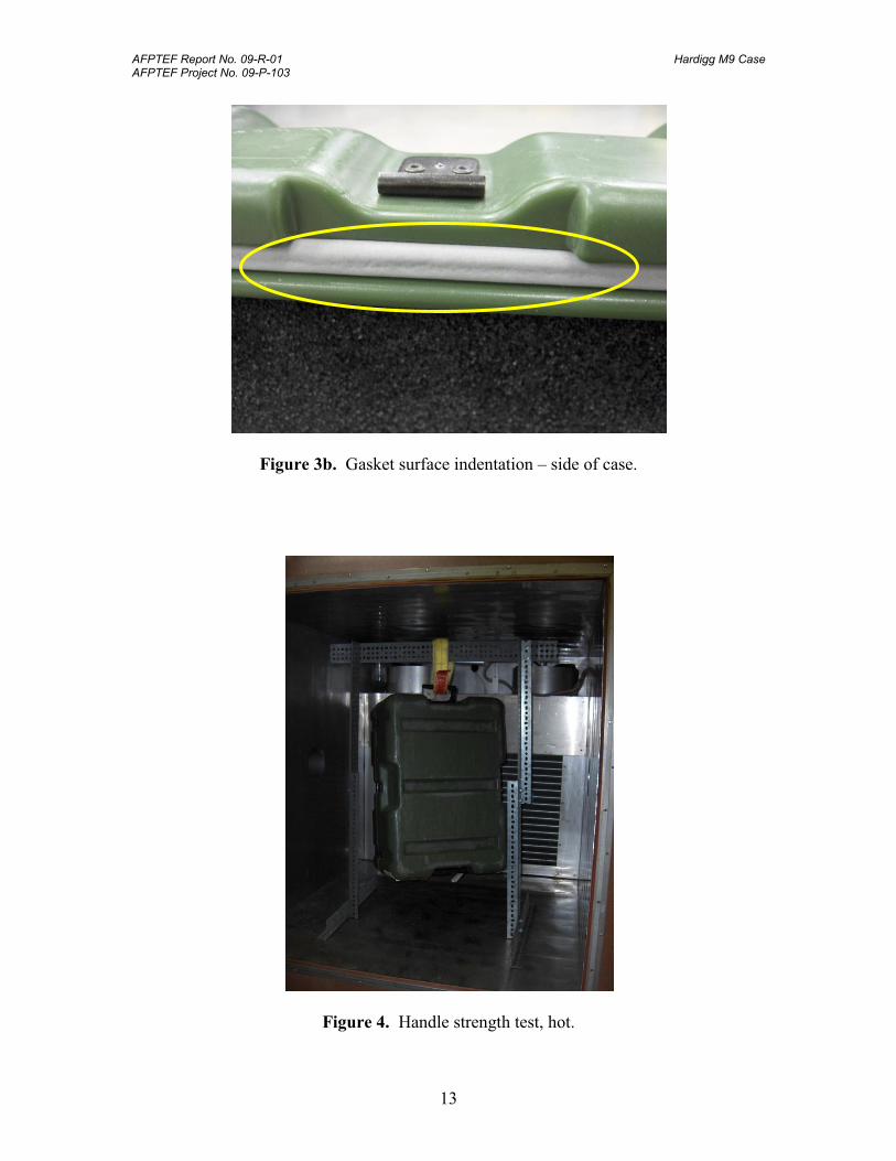
Results – Fail: The first container failed the leak test with a leak rate in excess
0.05 psi per minute. The second container failed the leak test with a leak rate of
approximately 0.10 psi per hour. Leaks were found around the entire perimeter
of both cases. Note the indentations found on the gasket surface at room
temperature (Appendix 2, Figure 3a and 3b). From a design standpoint, the
gasket material and/or the number of latches is inadequate for this case.
Note: The sample cases have been in service for 2-3 years. Therefore, if brand
new cases provide a satisfactory level of water-vapor-proof protection, it will not
last for more than 2-3 years.
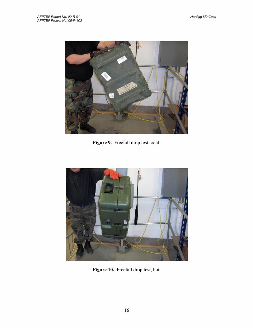
TEST SEQUENCE 2 – Handle Strength Test, Hot
Procedure: The case was suspended from one of the handles for 1 hour at a
temperature of 160oF (Appendix 2, Figure 4).
Results: Pass: There was a significant amount of deformation to the handle
immediately after the test (Appendix 2, Figure 5). After 24 hours, a lesser amount

AFPTEF Report No. 09-R-01 Hardigg M9 Case AFPTEF Project No. 09-P-103
3
of permanent deformation remained (Appendix 2, Figure 6), but the handle is still
functional. When raised and lowered slowly, the handle sticks and does not drop
freely to the side of the case (Appendix 2, Figure 7). If it is raised and released,
there is enough spring force to return the handle to the side of the case.
There was also a slight bowing-out of the left end of the case (Appendix 2, Figure
17) due to this test. This will not affect the ability of the case to protect the items.
However, if the case had passed the initial leak check, this deformation may have
diminished the sealing properties of the case.
TEST SEQUENCE 3 – Handle Strength Test, Cold
Procedure – The case was suspended from the opposite handle for 1 hour at a
temperature of -50oF (Appendix 2, Figure 8).
Results – Pass: The handle deformed temporarily to the point that, when released,
it did not drop freely to the side of the case. Within 24 hours the handle returned
to the original shape.
There was also a slight bowing-out of the right end of the case (Appendix 2,
Figure 18) due to this test. This will not affect the ability of the case to protect the
items. As with Test Sequence 2, if the case had passed the initial leak check, this
deformation may have diminished the sealing properties of the case.
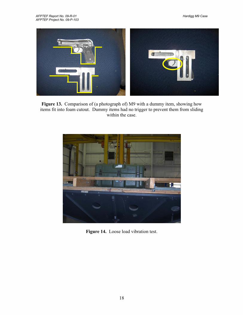
TEST SEQUENCE 4 – Freefall Drops, Cold
Procedure – The case was conditioned for 24 hours at a temperature of -40oF, and
then dropped six times from a height of 24 inches (Appendix 2, Figure 9). Impact
locations were as follows:
1. Top Face
2. Edge 1
3. Edge 2
4. Corner 1
5. Corner 2
6. Bottom Face
Results – Pass: The impacts caused no visible damage to either the container or
the items. There were slight indentations to the case from resting on the edge of
the drop testing platform.
TEST SEQUENCE 5 – Freefall Drops, Hot
Procedure – The case was conditioned for 24 hours at a temperature of 140oF, and
then dropped from a height of 24 inches (Appendix 2, Figure 10). Impact
locations were as follows:
AFPTEF Report No. 09-R-01 Hardigg M9 Case AFPTEF Project No. 09-P-103
4
1. Edge 3
2. Right Face
3. Front Face
4. Corner 3
5. Edge 4
6. Bottom Face
Results – Pass: The impacts caused no visible damage to either the container or
the items. There were slight indentations to the case from resting on the edge of
the drop testing platform (Appendix 2, Figure 11). Items also shifted around in
the case (Appendix 2, Figure 12), due to softness of the foam at high temperatures
and the shape of the dummy items (Appendix 2, Figure 13). However, the trigger
portion of a real M9 rests in the foam such that it prevents the item from sliding
around in the case.
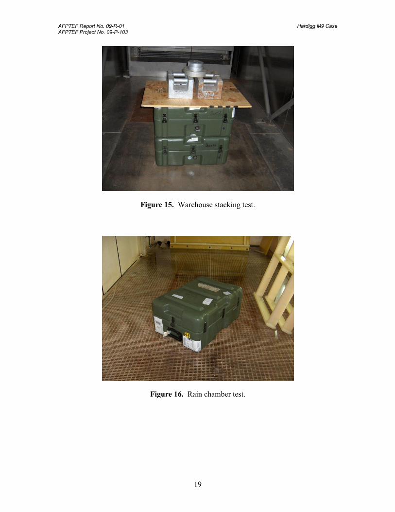
TEST SEQUENCE 6 – Loose-Load Vibration Test, Repetitive Shock
Procedure – A sheet of 3/4-inch plywood was bolted to the top of the vibration
table, and the container was placed on the plywood. Restraints were used to
prevent the container from sliding off the table. The container was allowed
approximately 1/2-inch unrestricted movement in the horizontal direction from
the centered position on the table (Appendix 2, Figure 14).
The table frequency was increased from 3.5 Hz until the container left the table
surface (approximately 4.0 Hz). At one-inch double amplitude, a 1/16-inch-thick
flat metal feeler could be slid freely between the table top and the container under
all points of the container. Repetitive shock testing was conducted for 2 hours at
ambient temperature.
Results – Pass: The loaded container was vibrated at 4.0 Hz for 2 hours. At the
end of testing there was no visible damage to the either the container or the item.
TEST SEQUENCE 7 – Warehouse Stacking
Procedure – A 250-pound static load, consisting of the spare weapons case (#1
from leak test), a sheet of plywood, and iron weights, was set on top of the test
case (Appendix 2, Figure 15). The stacked configuration was placed in an
environment at 140oF and 90% relative humidity for 24 hours. The chamber was
shut down, with the stacked configuration remaining in the closed chamber for 6
more days. Although test time was shortened from 168 hours as specified in the
test plan, 24 hours at the test point (140oF and 90% RH) is sufficient to expose
structural weakness of the container.
Results – Pass: There was no visible damage to the either the container or the
item.

AFPTEF Report No. 09-R-01 Hardigg M9 Case AFPTEF Project No. 09-P-103
5
TEST SEQUENCE 8 – Wind and Rain Exposure
Procedure – As a follow-on to the failed leak test, AFPTEF wanted to
demonstrate that the case would protect items from rain. The weapons case was
placed in a rain chamber and subjected to 5 in/hour rainfall with 40-mph wind for
a total of 90 minutes (Appendix 2, Figure 16). The case sat in two different
orientations, with edges 5 and 6 facing into the wind for 45 minutes each.
Results – Pass: There were no signs of water intrusion into the case.
TEST CONCLUSIONS – Aside from apparent degradation of the gasket that prevented
the case from sealing, there was no other damage, deformation or degradation of the case
or components that would permit physical or rain-water damage to the items, reduce case
strength, adversely affect safety during transport or storage, or interfere with manual
handling or use of the case.
CONCLUSIONS & RECOMMENDATIONS
Although the Hardigg M9 weapons case failed to achieve an adequate water-vapor-proof
seal, the case satisfied the remaining performance test requirements for level A
packaging. During testing, the case secured the items and protected them from physical
damage and rain intrusion. For corrosion protection of the items during worldwide
shipping and storage, AFPTEF recommends sealing each weapon in a separate water-
vapor-proof barrier bag prior to storage in the case.
AFPTEF Report No. 09-R-01 Hardigg M9 Case AFPTEF Project No. 09-P-103
6
APPENDICES
APPENDIX 1: Test Plan

AFPTEF Report No. 09-R-01 Hardigg M9 Case AFPTEF Project No. 09-P-103
7
AF PACKAGING TECHNOLOGY AND ENGINEERING FACILITY
(Container Test Plan)
CONTAINER SIZE (L x W x D) (IN)
INTERIOR: EXTERIOR:
WEIGHT (LB)
GROSS: TARE
CUBE (CU. FT)
ITEM NAME:
QUANTITY: DATE:
AFPTEF PROJECT NUMBER:
MANUFACTURER:
CONTAINER COST:CONTAINER NAME:
PACK DESCRIPTION:
CONDITIONING:
TEST
NO.
REF STD/SPEC
AND TEST METHOD ORPROCEDURE NO'S
TEST TITLE AND PARAMETERSCONTAINER
ORIENTATION
INSTRU-
MENTATION
COMMENTS:
PREPARED BY: APPROVED BY:
PAGE OF
Hardigg 472-M9-10-S
Ambient, 160oF, 140oF / 95% RH, -65oF, -40oF
1. Ambient temp. VisualInspection (VI), tape measure; Scale
Product examination.
Robbin L. Miller, Chief AFPTEF
1 3
Fully assembled container shall be weighed,measured, and all components, assembly and closure requirements examined for accordance with manufacturer instructions and documentation.
09-P-103
Michael R. Harff, Mechanical Engineer
26.5 x 19 x 13.5 41 1 Jan 09
(10) M-9s Hardigg
(10) M-9s
Ambient temp.
PASS/FAIL CRITERIA FOR ALL TESTS
There shall be no damage, deformation or degradation of the container or components that would permit damage to contents, prevent installation of components, reduce container strength or cause stacking instability, permit water to enter, adversely affect safety during transport or storage, interfere with container use. All components shall remain in place throughout testing.
2. Leak Check An initial leak test shall be performed prior to testing, and then performed after each test sequence to verify leakage integrity of the container. Pneumatic-pressure technique shall be used with a test pressure of 0.5 psig. Pressure loss shall not exceed 0.05 psi in 1 hour.
Weight Test.
Air pump, valves, fittings, digital manometer, and clock
MIL-STD-648DPara 5.6.2
N/A 4.220
Ambient temp. Scale
Left Handle3. Handle StrengthTest, HOT
Container shall be suspended for a duration of 1 hour from handle, at a temperature of 160oF .
Environmental chamber, hanging fixtureMIL-STD-648D
Para 5.8.5

AFPTEF Report No. 09-R-01 Hardigg M9 Case AFPTEF Project No. 09-P-103
8
AF PACKAGING TECHNOLOGY AND ENGINEERING FACILITY
(Container Test Plan)
CONTAINER SIZE (L x W x D) (IN)
INTERIOR: EXTERIOR:
WEIGHT (LB)
GROSS: ITEM:
CUBE (CU. FT)
ITEM NAME:
QUANTITY: DATE:
AFPTEF PROJECT NUMBER:
MANUFACTURER:
CONTAINER COST:CONTAINER NAME:
PACK DESCRIPTION:
CONDITIONING:
TEST
NO.
REF STD/SPEC
AND TEST METHOD ORPROCEDURE NO'S
TEST TITLE AND PARAMETERSCONTAINER
ORIENTATION
EQUIPMENT &
INSTRUMENTATION
COMMENTS:
PREPARED BY: APPROVED BY:
PAGE OF
Robbin L. Miller, Chief AFPTEF
2 3
Michael R. Harff, Mechanical Engineer
4.
09-P-103
Right Handle
5.
Handle StrengthTest, COLD
Container shall be suspended for a duration of 1 hour from handle, at a temperature of -65oF.
Environmental chamber, hanging fixtureMIL-STD-648D
Para 5.8.5
6.
Freefall Drops, COLD
Container shall be conditioned for up to 24 hours at -40oF, and then First Sequence of drops shall be performed with a drop height of 24 inches. All drops shall be performed within 10 minutes of removal from environmental chamber. Otherwise, container shall be placed in chamber for 1 hour prior to retesting.
ASTM D4169-08, A1.2.1, Assurance Level 1.ASTM D5276
Environmental chamber, drop tester, tape measure
Ambient7. Loose Load Vibration Test
Container with test load shall be tested as described with a dwell time of 2 hours, in one position.
Vibration table, controllerASTM D4169-08,
A1.6, Assurance Level 1. ASTM D999, Method A1
Hardigg 472-M9-10-S
41 1 Jan 09
(10) M-9s
(10) M-9s
N/A 4.220
Ambient, 160oF, 140oF / 95% RH, -65oF, -40oF
26.5 x 19 x 13.5
Hardigg
1. Edge #32. Right Face3. Front Face4. Corner #35. Edge #46. Bottom
1. Top2. Edge #13. Edge #24. Corner #15. Corner #26. Bottom
Environmental chamber, drop tester, tape measure
Freefall Drops, HOT
Container shall be conditioned for up to 24 hours at 140oF, and then Second Sequence of drops shall be performed with a drop height of 24 inches. All drops shall be performed within 10 minutes of removal from environmental chamber. Otherwise, container shall be placed in chamber for 1 hour prior to retesting.
ASTM D4169-08, A1.2.1, Assurance Level 1.ASTM D5276

AFPTEF Report No. 09-R-01 Hardigg M9 Case AFPTEF Project No. 09-P-103
9
AF PACKAGING TECHNOLOGY AND ENGINEERING FACILITY
(Container Test Plan)
CONTAINER SIZE (L x W x D) (IN)
INTERIOR: EXTERIOR:
WEIGHT (LB)
GROSS: ITEM:
CUBE (CU. FT)
ITEM NAME:
QUANTITY: DATE:
AFPTEF PROJECT NUMBER:
MANUFACTURER:
CONTAINER COST:CONTAINER NAME:
PACK DESCRIPTION:
CONDITIONING:
TEST
NO.
REF STD/SPEC
AND TEST METHOD ORPROCEDURE NO'S
TEST TITLE AND PARAMETERSCONTAINER
ORIENTATION
EQUIPMENT &
INSTRUMENTATION
COMMENTS:
PREPARED BY: APPROVED BY:
PAGE OF
Robbin L. Miller, Chief AFPTEF
3 3
Michael R. Harff, Mechanical Engineer
140oF / 95% RH8. Stack Test An identical container base shall be placed on top of the test container and a stack load shall be placed on that container base, for a total load of 246 lb. Load shall be left in place for 168 hours. Container shall be examined for damage at the end of 168 hours.
Load = Mass*(H/h – 1)*FoS: Mass = 41 lb, H/h = 5, FoS (Factor of Safety) = 1.5
MIL-STD-648D, para. D.6(a)
09-P-103
Environmental chamber, iron weights
1. Edge #5 facing into the wind
2. Edge #6 facing into the wind
9. Wind and Rain Exposure
Container shall be placed in rain chamber and subjected to 40-mph wind and rain at 5 in/hour for a total of 1 hour. Container shall be examined for water intrusion at the end of 1 hour.
Rain chamber
Hardigg 472-M9-10-S
41 1 Jan 09
(10) M-9s
(10) M-9s
N/A 4.220
Ambient, 160oF, 140oF / 95% RH, -65oF, -40oF
26.5 x 19 x 13.5
Hardigg
AFPTEF Report No. 09-R-01 Hardigg M9 Case AFPTEF Project No. 09-P-103
10
APPENDIX 2: Case and Testing Photographs

AFPTEF Report No. 09-R-01 Hardigg M9 Case AFPTEF Project No. 09-P-103
11
Figure 1a. Case with dummy loads inserted.
Figure 1b. Edge and Corner Locations for Testing.

AFPTEF Report No. 09-R-01 Hardigg M9 Case AFPTEF Project No. 09-P-103
12
Figure 2. Leak test setup for case #2.
Figure 3a. Gasket surface indentation – corner of case.
AFPTEF Report No. 09-R-01 Hardigg M9 Case AFPTEF Project No. 09-P-103
13
Figure 3b. Gasket surface indentation – side of case.
Figure 4. Handle strength test, hot.

AFPTEF Report No. 09-R-01 Hardigg M9 Case AFPTEF Project No. 09-P-103
14
Figure 5. Handle deformation immediately after hot strength test.
Figure 6. Permanent deformation from hot handle strength test (A), and untested handle
(B).
A B

AFPTEF Report No. 09-R-01 Hardigg M9 Case AFPTEF Project No. 09-P-103
15
Figure 7. Sticking of tested handle.
Figure 8. Handle strength test, cold.
AFPTEF Report No. 09-R-01 Hardigg M9 Case AFPTEF Project No. 09-P-103
16
Figure 9. Freefall drop test, cold.
Figure 10. Freefall drop test, hot.

AFPTEF Report No. 09-R-01 Hardigg M9 Case AFPTEF Project No. 09-P-103
17
Figure 11. Scratches due to contact with edge of the drop tester.
Figure 12. Shifting of items within the case.
AFPTEF Report No. 09-R-01 Hardigg M9 Case AFPTEF Project No. 09-P-103
18
Figure 13. Comparison of (a photograph of) M9 with a dummy item, showing how
items fit into foam cutout. Dummy items had no trigger to prevent them from sliding
within the case.
Figure 14. Loose load vibration test.
AFPTEF Report No. 09-R-01 Hardigg M9 Case AFPTEF Project No. 09-P-103
19
Figure 15. Warehouse stacking test.
Figure 16. Rain chamber test.
AFPTEF Report No. 09-R-01 Hardigg M9 Case AFPTEF Project No. 09-P-103
20
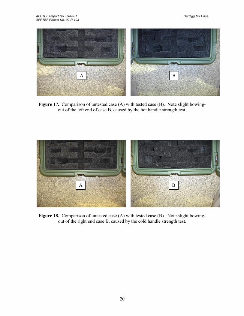
Figure 17. Comparison of untested case (A) with tested case (B). Note slight bowing-
out of the left end of case B, caused by the hot handle strength test.
Figure 18. Comparison of untested case (A) with tested case (B). Note slight bowing-
out of the right end case B, caused by the cold handle strength test.
A B
A B

AFPTEF Report No. 09-R-01 Hardigg M9 Case AFPTEF Project No. 09-P-103
21
APPENDIX 3: Test Instrumentation

AFPTEF Report No. 09-R-01 Hardigg M9 Case AFPTEF Project No. 09-P-103
22
PRESSURE TEST EQUIPMENT - Test sequence 1
EQUIPMENT MANUFACTURER MODEL SN CAL. DATE
Digital Manometer Yokogawa 2655 82DJ6001 Dec 08
Digital Manometer Yokogawa 2655 82DJ6009 Dec 08
VIBRATION TEST EQUIPMENT - Test sequence 5
EQUIPMENT MANUFACTURER MODEL SN CAL. DATE
Servohydraulic Vibration
Machine Team Corp. Special 1988 N/A
Feedback Hardware
Controller Dactron Corp.
PCI DSP Card
Front End DSP Box
2208515
4544828
Aug 08
N/A
Feedback Software
Controller Dactron Corp. Version 2.1 N/A N/A
Table Feedback
Accelerometer Endevco 2271AM20 103870 Nov 07
Feedback Amplifier Endevco 2775A EL65 N/A

AFPTEF Report No. 09-R-01 Hardigg M9 Case AFPTEF Project No. 09-P-103
23
APPENDIX 4: Distribution List

AFPTEF Report No. 09-R-01 Hardigg M9 Case AFPTEF Project No. 09-P-103
24
DISTRIBUTION LIST
DTIC/O
DEFENSE TECHNICAL INFORMATION CENTER
FORT BELVOIR VA 22060-6218
403 SCMS/CL
5215 THURLOW ST, STE 5
BLDG 70C
WRIGHT-PATTERSON AFB OH 45433-5547
66 MSG/LGS
ATTN WILLIAM PERKINS
29 RANDOLPH RD
BLDG 1102D
HANSCOM AFB, MA 01731
418 SCMS/GULAAA
ATTN THELMA LOOCK
7973 UTILITY DR
BLDG 1135
HILL AFB UT 84056
420 SCMS/GUMAA
ATTN CAROL BAXTER
7701 ARNOLD ST
BLDG 1, RM 112
TINKER AFB OK 73145
406 SCMS/GUMA
ATTN WAYNE OSBORN
375 PERRY ST
BLDG 255
ROBINS AFB GA 31098
575 CBSS/GBLC
ATTN JUNE SIMS
460 RICHARD RAY BLVD STE 221
ROBINS AFB GA 31098

AFPTEF Report No. 09-R-01 Hardigg M9 Case AFPTEF Project No. 09-P-103
25
APPENDIX 5: Report Documentation

AFPTEF Report No. 09-R-01 Hardigg M9 Case AFPTEF Project No. 09-P-103
26
REPORT DOCUMENTATION PAGE Form Approved
OMB No. 0704-0188
Public reporting burden for this collection of information is estimated to average 1 hour per response, including the time for reviewing instructions, searching data sources, gathering and maintaining the data needed, and completing and reviewing the collection of information. Send comments regarding this burden estimate or any other aspect of this collection of information, including suggestions for reducing this burden to Washington Headquarters Service, Directorate for Information Operations and Reports, 1215 Jefferson Davis Highway, Suite 1204, Arlington, VA 22202-4302, and to the Office of Management and Budget, Paperwork Reduction Project (0704-0188) Washington, DC 20503.
PLEASE DO NOT RETURN YOUR FORM TO THE ABOVE ADDRESS. 1. REPORT DATE (DD-MM-YYYY) 20-02-2009
2. REPORT TYPE Technical Final Project Report
3. DATES COVERED (From - To) 22-01-2009 to 19-02-2009
4. TITLE AND SUBTITLE Performance Testing of the Hardigg M9 Weapons Case
5a. CONTRACT NUMBER
5b. GRANT NUMBER
5c. PROGRAM ELEMENT NUMBER
6. AUTHOR(S) Michael R. Harff, Qualification Test Engineer [email protected] DSN 787-4519 Comm. (937)257-4519
5d. PROJECT NUMBER 09-P-103
5e. TASK NUMBER
5f. WORK UNIT NUMBER
7. PERFORMING ORGANIZATION NAME(S) AND ADDRESS(ES) Air Force Packaging Technology & Engineering Facility 403 SCMS / GUEB 5215 Thurlow St, Ste. 5 Wright-Patterson AFB, OH 45433-5547
8. PERFORMING ORGANIZATION REPORT NUMBER 09-R-01
9. SPONSORING/MONITORING AGENCY NAME(S) AND ADDRESS(ES)
10. SPONSOR/MONITOR'S ACRONYM(S)
11. SPONSORING/MONITORING AGENCY REPORT NUMBER
12. DISTRIBUTION AVAILABILITY STATEMENT A
13. SUPPLEMENTARY NOTES
14. ABSTRACT The Air Force Packaging Technology Engineering Facility (AFPTEF) carried out performance testing of the Hardigg M-9 weapons case, at the request of the 66 MSG/LRDS at Hanscom AFB, MA. Tests were conducted in accordance with ASTM D4169, DC-18 for assurance level I, and in accordance with MIL-STD-648C. The weapons case did not pass the initial leak check, and therefore cannot protect the items from exposure to humidity. Additionally, there were slight permanent deformations: bowing-out at the ends of the case due to hot/cold handle pull tests, and bowing of the loaded handle due to the hot handle pull test. However, these deformations do not affect the ability of the case to secure the items and provide adequate physical protection. Sealing each weapon in a separate water-vapor-proof barrier bag prior to storage in the case will provide adequate environmental protection. 15. SUBJECT TERMS M9, M9 Shipping and Storage, Weapons Case Test, Hardigg Case, Small Weapons Case
16. SECURITY CLASSIFICATION OF: 17. LIMITATION OF ABSTRACT UU
18. NUMBER OF PAGES 26
19a. NAME OF RESPONSIBLE PERSON
Michael R. Harff
a. REPORT
U b. ABSTRACT
U c. THIS PAGE
U 19b. TELEPONE NUMBER (Include area code)
(937)257-4519