
Hard x-ray emission spectroscopy: a powerful tool for the ... · Keywords: magnetic semiconductors...
21
Hard x-ray emission spectroscopy: a powerful tool for the characterization of magnetic semiconductors M. Rovezzi 1, * and P. Glatzel 1 1 European Synchrotron Radiation Facility, 6 rue Jules Horowitz, 38043 Grenoble, France (Dated: January 20, 2014) This review aims to introduce the x-ray emission spectroscopy (XES) and resonant inelastic x-ray scattering (RIXS) techniques to the materials scientist working with magnetic semiconductors (e.g. semiconductors doped with 3d transition metals) for applications in the field of spin-electronics. We focus our attention on the hard part of the x-ray spectrum (above 3 keV) in order to demonstrate a powerful element- and orbital-selective characterization tool in the study of bulk electronic structure. XES and RIXS are photon-in/photon-out second order optical processes described by the Kramers-Heisenberg formula. Nowadays, the availability of third generation synchrotron radiation sources permits applying such techniques also to dilute materials, opening the way for a detailed atomic characterization of impurity-driven materials. We present the Kβ XES as a tool to study the occupied valence states (directly, via valence-to-core transitions) and to probe the local spin angular momentum (indirectly, via intra-atomic exchange interaction). The spin sensitivity is employed, in turn, to study the spin-polarised unoccupied states. Finally, the combination of RIXS with magnetic circular dichroism (RIXS-MCD) extends the possibilities of standard magnetic characterization tools. PACS numbers: 78.70.Dm, 78.70.En, 78.70.Ck, 71.55.-i, 71.15.-m, 71.20.-b, 75.50.Pp, 75.47.Lx, 61.05.cj, 07.85.Qe, 07.85.Nc, 32.30.Rj, 32.50.+d, 32.70.-n, 32.80.-t Keywords: magnetic semiconductors characterization, x-ray emission spectroscopy, resonant inelastic x-ray scattering, spintronics, synchrotron radiation I. INTRODUCTION Semiconductors doped with few percent (10 20 –10 21 at/cm 3 ) of magnetic elements such as transition metals (TM) or rare earth elements (RE) are promising building blocks for semiconductor-based spin-electronics (Dietl, 2010; Dietl and Ohno, 2013)(spintronics). In the dilute magnetic semiconductor (DMS) model, the TM (RE) dopants randomly substitute in the host semiconductor and, due to the unpaired d (f ) states, bring a local net magnetic moment. These local moments, via inter-atomic exchange interactions (eventually mediated by defects or carriers), bring magnetic properties to the semiconductor, leading to an overall half-metallic behavior (Coey and Sanvito, 2004), that is, the presence of spin polarization at the Fermi level. Such materials can be used then as injector or detector for spin-polarised currents in semiconductors and permit realising spintronics devices as, for example, the proposed spin field-effect transistor (Datta and Das, 1990), overcoming the conductivity mismatch problem (Schmidt et al., 2000) that arises for ferromagnetic- * [email protected]; this is an author-created, un-copyedited version of an article accepted for publication in Semiconductor Science and Technol- ogy. IOP Publishing Ltd is not responsible for any errors or omissions in this version of the manuscript or any version derived from it. The definitive publisher-authenticated version is available online at doi:10.1088/0268- 1242/29/2/023002; please cite this paper as: Semicond. Sci. Technol. 29 (2014) 023002. metal/semiconductor hetero-structures. It is important to clarify that non-magnetic semiconductors such as II-VI or III-V alloys (e.g. GaAs, GaN or ZnO) have been identified historically as host materials for DMS, because their epitaxial growth is of high quality and they can be easily integrated in CMOS technology (what is currently used for constructing integrated circuits). Recently, pushed by the advances in epitaxial growth of oxide materials (Opel, 2012; Bibes et al., 2011), also bulk magnetic oxides such as transition metal oxides are considered for semiconductor spintronics. We will focus mainly on DMS because these materials represent an ideal workbench for testing new and exciting effects as quantum spintronics (Awschalom et al., 2013; Koenraad and Flatté, 2011; George et al., 2013) (also known as solotronics) or the spin solar cell (Jansen, 2013; Endres et al., 2013) and others (Sinova and Žuti´ c, 2012). DMS currently suffer from low (ferro)magnetic transition temperatures. In order to obtain the magnetic coupling persisting well above room temperature, the concentration of the active dopants is pushed (in most cases) far above the thermodynamic solubility limit by out-of-equilibrium epitaxial growth methods (e.g. low temperature molecular beam epitaxy). This can cause side effects such as the incor- poration of counter-productive defects (e.g. Mn interstitials in Ga 1-x Mn x As) or a chemical phase separation, where the density of the magnetic impurities is not constant over the host crystal (condensed magnetic semiconductors, CMS). Two recent reviews (Bonanni and Dietl, 2010; Sato et al., arXiv:1312.0399v2 [cond-mat.mtrl-sci] 17 Jan 2014
Transcript of Hard x-ray emission spectroscopy: a powerful tool for the ... · Keywords: magnetic semiconductors...

Hard x-ray emission spectroscopy: a powerful tool for the characterizationof magnetic semiconductors
M. Rovezzi1, ∗ and P. Glatzel11European Synchrotron Radiation Facility,6 rue Jules Horowitz,38043 Grenoble,France
(Dated: January 20, 2014)
This review aims to introduce the x-ray emission spectroscopy (XES) and resonant inelastic x-rayscattering (RIXS) techniques to the materials scientist working with magnetic semiconductors (e.g.semiconductors doped with 3d transition metals) for applications in the field of spin-electronics. Wefocus our attention on the hard part of the x-ray spectrum (above 3 keV) in order to demonstratea powerful element- and orbital-selective characterization tool in the study of bulk electronicstructure. XES and RIXS are photon-in/photon-out second order optical processes described by theKramers-Heisenberg formula. Nowadays, the availability of third generation synchrotron radiationsources permits applying such techniques also to dilute materials, opening the way for a detailedatomic characterization of impurity-driven materials. We present the Kβ XES as a tool to study theoccupied valence states (directly, via valence-to-core transitions) and to probe the local spin angularmomentum (indirectly, via intra-atomic exchange interaction). The spin sensitivity is employed, inturn, to study the spin-polarised unoccupied states. Finally, the combination of RIXS with magneticcircular dichroism (RIXS-MCD) extends the possibilities of standard magnetic characterization tools.
PACS numbers: 78.70.Dm, 78.70.En, 78.70.Ck, 71.55.-i, 71.15.-m, 71.20.-b, 75.50.Pp, 75.47.Lx, 61.05.cj,07.85.Qe, 07.85.Nc, 32.30.Rj, 32.50.+d, 32.70.-n, 32.80.-tKeywords: magnetic semiconductors characterization, x-ray emission spectroscopy, resonant inelastic x-rayscattering, spintronics, synchrotron radiation
I. INTRODUCTION
Semiconductors doped with few percent (1020–1021
at/cm3) of magnetic elements such as transition metals(TM) or rare earth elements (RE) are promising buildingblocks for semiconductor-based spin-electronics (Dietl, 2010;Dietl and Ohno, 2013) (spintronics). In the dilute magneticsemiconductor (DMS) model, the TM (RE) dopants randomlysubstitute in the host semiconductor and, due to the unpairedd (f ) states, bring a local net magnetic moment. These localmoments, via inter-atomic exchange interactions (eventuallymediated by defects or carriers), bring magnetic propertiesto the semiconductor, leading to an overall half-metallicbehavior (Coey and Sanvito, 2004), that is, the presence ofspin polarization at the Fermi level. Such materials can beused then as injector or detector for spin-polarised currents insemiconductors and permit realising spintronics devices as,for example, the proposed spin field-effect transistor (Dattaand Das, 1990), overcoming the conductivity mismatchproblem (Schmidt et al., 2000) that arises for ferromagnetic-
∗ [email protected]; this is an author-created, un-copyedited version ofan article accepted for publication in Semiconductor Science and Technol-ogy. IOP Publishing Ltd is not responsible for any errors or omissions inthis version of the manuscript or any version derived from it. The definitivepublisher-authenticated version is available online at doi:10.1088/0268-1242/29/2/023002; please cite this paper as: Semicond. Sci. Technol.29 (2014) 023002.
metal/semiconductor hetero-structures. It is important toclarify that non-magnetic semiconductors such as II-VI orIII-V alloys (e.g. GaAs, GaN or ZnO) have been identifiedhistorically as host materials for DMS, because their epitaxialgrowth is of high quality and they can be easily integrated inCMOS technology (what is currently used for constructingintegrated circuits). Recently, pushed by the advances inepitaxial growth of oxide materials (Opel, 2012; Bibes et al.,2011), also bulk magnetic oxides such as transition metaloxides are considered for semiconductor spintronics. Wewill focus mainly on DMS because these materials representan ideal workbench for testing new and exciting effects asquantum spintronics (Awschalom et al., 2013; Koenraad andFlatté, 2011; George et al., 2013) (also known as solotronics)or the spin solar cell (Jansen, 2013; Endres et al., 2013) andothers (Sinova and Žutic, 2012).DMS currently suffer from low (ferro)magnetic transitiontemperatures. In order to obtain the magnetic couplingpersisting well above room temperature, the concentrationof the active dopants is pushed (in most cases) far abovethe thermodynamic solubility limit by out-of-equilibriumepitaxial growth methods (e.g. low temperature molecularbeam epitaxy). This can cause side effects such as the incor-poration of counter-productive defects (e.g. Mn interstitialsin Ga1−xMnxAs) or a chemical phase separation, where thedensity of the magnetic impurities is not constant over thehost crystal (condensed magnetic semiconductors, CMS).Two recent reviews (Bonanni and Dietl, 2010; Sato et al.,
arX
iv:1
312.
0399
v2 [
cond
-mat
.mtr
l-sc
i] 1
7 Ja
n 20
14
2
2010) describe in detail the status of current research onDMS/CMS both from the experimental and theoretical pointof view. They show a growing consensus that theorical resultscan drive the experiments in the optimization of new andexciting materials only if an accurate characterization at thenano-scale and at bulk level is put in place (Zunger et al.,2010).In order to tackle this point, we review a spectroscopictechnique, the hard x-ray emission spectroscopy with syn-chrotron radiation (resonant inelastic x-ray scattering, RIXS)that is a powerful tool in characterizing such materials. Itis a direct feedback for the scientists who need to engineertheir materials at the nano-scale (bottom-up approach) viaa fine control of their atomic and electronic structure. Thispermits realizing relevant devices and to explore new ideasand concepts in spintronics. The application of RIXS todoped semiconductors is stimulating also for the theoreticiansaiming to calculate experimental (spectroscopic) observables.In fact, RIXS permits combining two theoretical approachesto the description of the electronic structure of matter: bandcalculations based on the density functional theory (DFT) andatomic calculations based on the ligand field multiplet theory(LFMT). In fact, on one hand, DMS are well described byDFT as periodic systems and, on the other hand, DMS can bemodeled by the LFMT model as a deep impurity in a crystalfield.Being naturally element and spin/orbital angular momentumselective, x-ray spectroscopy permits studying the source ofthe observed macroscopic magnetism from a local structuraland electronic point of view. X-ray absorption spectroscopy(XAS) is one of the well established and widely used tools inx-ray spectroscopy. In XAS, an incoming photon (of energy~ωin) excites an inner-shell electron to an unoccupied level,leaving the system in an excited state with a core hole thatlives for a certain time, τ , that is linked to the uncertaintyin its energy, Γ, via the Heisenberg principle: Γτ ≥ ~/2(e.g. a lifetime of 1 fs implies a broadening of ≈ 0.1 eV).Experimentally, XAS is observed as discontinuities (theabsorption edges) in the absorption coefficient, µ(~ωin). Ina one-electron picture, the absorption edges mainly arisefrom electric dipole transitions (∆l = ±1), that is, transitionsto the empty partial density of states (PDOS) - the densityof states projected on the orbital angular momentum, l, ofthe absorbing atom. Thus, the orbitals with p symmetryare probed in K, L1 and M1 edges (s → p), the d in theL2,3 and M2,3 (p → d) and the f in the M4,5 (d → f ). Byscanning the incoming energy around the absorption edgeof a given element in the sample, the spectroscopist candescribe the atomic and electronic structure of the system,either via a fingerprint approach, based on the use of modelcompounds, or supported by calculations, based on quantummechanics. The emitted photoelectron wave can be viewedas scattering with the neighboring atoms and interferingwith itself. This gives rise to the fine structure observed inthe absorption coefficient. The XANES (x-ray absorptionnear-edge structure) and EXAFS (extended x-ray absorption
fine structure) techniques (Lee et al., 1981), described by themultiple scattering theory (Rehr, 2000), permit extracting thelocal geometry/symmetry and the bond distances, plus thecoordination numbers and disorder from the analysis of thefine structure. XANES and EXAFS have been successfullyapplied to the geometric structure analysis in semiconductorheterostructures (Boscherini, 2008), DMS/CMS (Rovezzi,2009; D’Acapito, 2011) and low-dimensional systems (Minoet al., 2013).XAS can be used also as an element-selective magnetometerby recording the difference in absorption of linearly/circularlypolarised light in a presence of a magnetic field, the x-raymagnetic linear/circular dichroism (XMLD/XMCD) tech-nique (Stöhr, 1999). This is an advantage with respect tothose techniques where the whole sample response to anexternal perturbation is measured (e.g. superconductingquantum interference device magnetometry (Sawicki et al.,2011) or electron paramagnetic resonance (Wilamowskiet al., 2011)). With respect to DMS/CMS, XMCD was suc-cessfully combined with the x-ray (natural) linear dichroism(Brouder, 1990) (XLD) and systematically applied to thestudy of Zn1−xCoxO to link the local magnetic and structuralproperties (Ney et al., 2010). For 3d TM, XMCD is usuallymeasured at the L edges, residing in the soft x-ray region(below 1 keV) or at the K edges, residing in the hard part ofthe spectrum (above 3 keV). XMCD at the L edge has theadvantage of accessing the partially filled d orbitals via directelectric dipole transitions and the possibility to separate thespin and orbital contribution to the magnetic moment via sumrules (Thole et al., 1992; Carra et al., 1993). XMCD at the Kedge probes only the orbital component and results in a verysmall signal (≈ 10−3 times smaller that XLD). The advan-tages in using hard x-rays consist in the sample environmentand the bulk sensitivity. A vacuum environment around thesample is not required with hard x-rays, thus it is possible tomeasure in operando devices or in extreme conditions (e.g.high pressure). Furthermore, the higher penetration depthpermits probing bulk properties and access buried interfacesor superstructures (e.g. two-dimensional electron/hole gases)that are the relevant structures of real devices to study spintransport mechanisms. Soft x-rays are suitable in the case ofthin films (few tens of nm thick) deposited on a substrate,where the electron yield (EY) detection is used as surfaceprobe, while the fluorescence yield (FY) as representativeof the full thickness. Nevertheless, FY suffers from strongself-absorption effects and is not a true measurement ofthe linear absorption coefficient as obtained in transmissionmeasurements or EY (de Groot et al., 1994a; Kurian et al.,2012). This has relevant consequences on the study ofmagnetic materials with soft x-rays XMCD because it meansthat it is not possible to compare EY measurements to FYones and, most importantly, it implies the non-applicabilityof sum rules. An alternative method based on x-ray emissionhas been proposed recently (Achkar et al., 2011a,b). Toovercome those difficulties, the use of a hard x-ray probe inan inelastic scattering configuration is gaining momentum.
3
By working in an energy loss scheme (inelastic scattering)it is possible to reach the same final states reachable withsoft x-rays in a second order process, that is, by passingvia an intermediate state that is excited resonantly, stronglyenhancing the spectral features (Carra et al., 1995).With respect to XAS, in this review we focus on the lowenergy range of the K edge, the pre-edge features (Westreet al., 1997; Yamamoto, 2008; de Groot et al., 2009). Thesefeatures are enhanced by collecting the fluorescence channelacross the absorption edge with a small energy bandwidth, asobtained via a wavelength dispersive spectrometer (WDS).This technique is nowadays referred to high energy resolutionfluorescence detected (HERFD) XAS (Glatzel et al., 2013).The acronym RIXS here includes resonant x-ray emissionspectroscopy (RXES), that is, the direct RIXS of Ref. Amentet al., 2011 or the spectator RXES of Ref. Kotani et al.,2012. In addition, the initial and intermediate core holestates are also reported for clarity. The RIXS done bycollecting the Kα1 emission line is denoted as 1s2p3/2 RIXS.Whe refer then to x-ray emission spectroscopy (XES) asthe fluorescence yield measured after photoinization andscanned via a WDS. The presentation of XES and RIXSfollows previous reviews (Glatzel et al., 2013; de Groot,2001; Glatzel and Bergmann, 2005; Glatzel et al., 2009;Bergmann and Glatzel, 2009; Glatzel and Juhin, 2013) byextending the applicability to magnetic semiconductors. Thespecific case of non-resonant inelastic x-ray scattering (Rueffand Shukla, 2010), the x-ray Raman scattering (XRS), is nottreated here. XRS permits measuring the K-edge of lightelements (e.g. C, N, O) with hard x-rays (Huotari et al.,2012; Wernet et al., 2004). A possible application of XRS isthe study of doping mechanism with shallow impurities (asthe case of co-doping in magnetic semiconductors), but it iscurrently not applicable to dilute systems. The very low crosssection limits the application of XRS. XES and RIXS are alsoextensively employed in the soft x-ray energy range (Amentet al., 2011; Gel’mukhanov and Ågren, 1999; Kotani andShin, 2001). One relevant application is the element-selectivemapping of the valence and conduction bands (Preston et al.,2008; Lüning and Hague, 2008). RIXS is also often used tostudy collective excitations in systems with long-range order.The analysis of the energy dispersion as a function of themomentum transfer permitted identifying a two-directionalmodulation in the charge density of high-temperature su-perconductors (Ghiringhelli et al., 2012) and the magnondispersion (Braicovich et al., 2010). Another study, using softx-rays at the L edge of Cu in a quasi one-dimensional cuprate(Sr2CuO3), proved the existence of long-sought orbitons(Schlappa et al., 2012). Reviewing RIXS employed to probethe dispersion of quasiparticles and their fractionalization isbeyond our present scope. The interested reader can refer toRef. Ament et al., 2011 (and references therein).The paper is organised as follows. We start by givingsome elements of the RIXS theory and present the Kramers-Heisenberg formula in § II. This is followed by an overview ofcurrent methods employed in calculating x-ray spectra (§ III).
The experiment and the required instrumentation to performXES and RIXS are presented in § IV. The features of a RIXSintensity plane are then discussed in § V. The informationcontent of the K emission lines is described in § VI, with afocus on 3d TM valence-to-core XES. The Kβ core-to-coretransitions as an indirect probe of the local spin moment arepresented in § VII with a selected application to the study ofGa1−x−yMnxMgyN. This selectivity permits collecting spin-and site-selective XAS (§ VII.A). A combination of RIXSwith magnetic circular dichroism (RIXS-MCD) is presentedin § VIII. Finally, in § IX, our views on future developmentsof the technique in the study of magnetic semiconductors aregiven.
II. KRAMERS-HEISENBERG FORMALISM
We present in the following a brief introduction to the the-ory of x-ray emission spectroscopy. A more comprehensivetreatment of the theory is available in recent review papers andbooks: Gel’mukhanov and Ågren (Gel’mukhanov and Ågren,1999; Ågren and Gel’mukhanov, 2000) (molecules), de Grootand Kotani (De Groot and Kotani, 2008) (hard and soft x-raysin condensed matter), Rueff and Shulka (Rueff and Shukla,2010) (high pressure applications) and Ament et al. (Amentet al., 2011) (elementary excitations in solid state physics). X-
x
y
z
(ωin,kin, εin)
(ωout,kout, εout)
q
φ
θ
ac
b
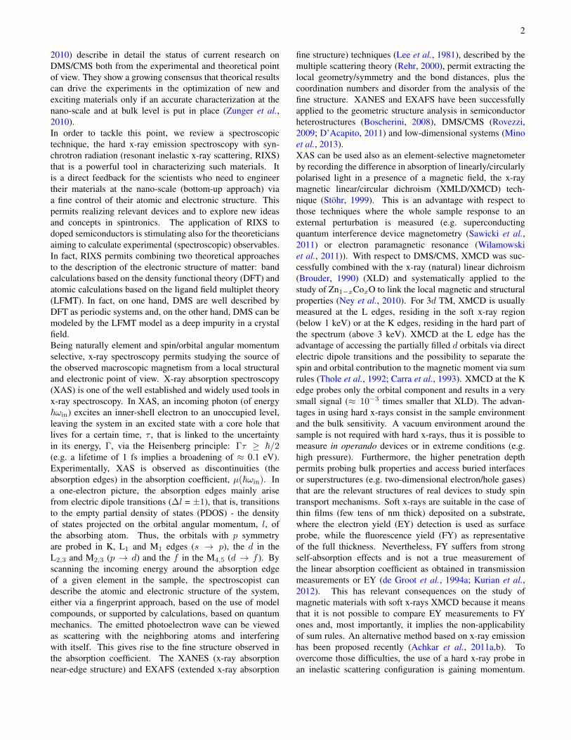
Figure 1 Scattering geometry for photon-in/photon-out spec-troscopy. For φ = 0, εin points along x. The gray box representsthe sample as a single crystal, where the cell vectors (a, b, c) are notoriented with respect to the surface in order to emphasise the polar-ization effects.
ray emission is a secondary process that occurs after creationof a vacancy in an inner-shell of the element of interest. Inmost applications this vacancy is created after photoexcitation
4
and x-ray emission becomes a photon-in/photon-out processand therefore an x-ray scattering phenomenon. Alternatives tophotoexcitation exist (e.g. ion or electron bombardement, ra-dioactive isotopes) but the theoretical treatment in these casesonly requires minor adjustments with respect to the follow-ing considerations. In the general description of a scatteringprocess (cf. figure 1 for the scattering geometry), a photon ofenergy ~ωin, wave vector kin and unit polarization vector εin
is scattered by the sample with ground state eigenfunction |g〉.A photon is emitted into a solid angle dΩ described by a po-lar angle θ and azimuthal angle φ. The scattered photon hasenergy ~ωout, wave vector kout and polarization εout. The en-ergy ~ω = ~(ωin−ωout) and momentum ~q = ~(kin−kout)are transferred to the sample that consequently makes a transi-tion from the ground state |g〉 with energy Eg to the final state|f〉 with energy Ef . The derivation of the double differen-tial scattering cross-section (DDSCS), d2σ/(dΩd~ωout), bymeans of second-order perturbation treatment can be foundin many textbooks (e.g. Schülke (Schülke, 2007) and Saku-rai (Sakurai, 1967)). The x-ray electromagnetic field is repre-sented by its vector potentialA. By neglecting the interactionof the magnetic field with the electron spin, the interactionHamiltonian is written (in SI units) as (Ament et al., 2011)
Hint =e2
2m
∑j
A(rj)2 +
e
m
∑j
pj ·A(rj) (1)
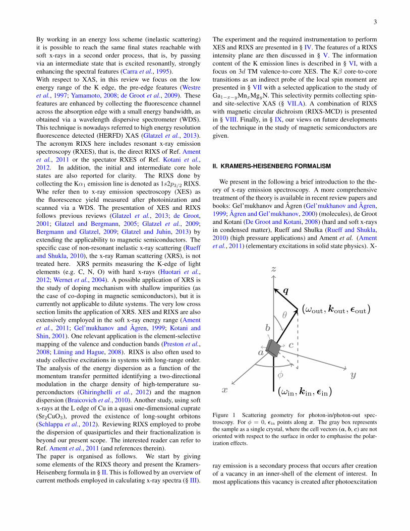
where pj is the momentum of the j-th target electron. Thetransition probability is given by the golden rule 〈s2|T |s1〉where T is a transition operator connecting two eigenstates.The term containing A2 does not involve the creation of aphoton-less intermediate state and can therefore be describedas a one-step scattering process (first order perturbation the-ory term). It gives rise to non-resonant scattering and can,apart from a few exceptions, not be used for an element-selective spectroscopy. The non-resonant term accounts forelastic Thomson scattering and inelastic Raman and Comptonscattering. Inelastic scattering may give an element-selectivesignature if the energy transfer corresponds to an absorptionedge (Schülke, 2007) (the case of XRS).The term containing p ·A contributes to the second order per-turbation term and causes annihilation of the incoming photonand thus the creation of an intermediate state that lives for atime τ and decays upon emission (creation) of a photon. Thetechnique is element-selective if the intermediate state can berepresented by an electron configuration that contains a hole ina core level of the element of interest. As in example, for Mnthis would be the levels 1s, 2s, . . . , 3p (cf. figure 2). We referto the resonant term as the Kramers-Heisenberg cross section.This term governs x-ray absorption (when considered as co-herent elastic forward scattering) and x-ray emission includ-ing all resonant scattering processes. The interaction termscan be treated separately, assuming implicitly that the exper-imental conditions are chosen such that one term dominates.Other terms and interference with them are not taken into ac-count. Removing unimportant factors, the essential part of
Total
Energy
MnIII 3d4
1s13d4(p)1
2p53d4(p)1
1s13d5
3d5L
energy
2p53d5
K pre-edge
K edge
3p53d4(p)1
3p53d5
M-edge
Ka
Kb
L-edge
UV-Vis 3d4
n
f
g
n
n
Figure 2 Total energy diagram of a system containing Mn in for-mal oxidation state III. The energy levels for the ground (|g〉), inter-mediate (|n〉) and final (|f〉) states are approximated using atomicconfigurations and a single-particle picture of the electronic transi-tions. Closed shells are omitted for clarity. Black lines indicate thateach configuration corresponds to a collection of several many-bodystates. Rectangles symbolise a band state, where the notation (p)represents mixed states between the atomic 4p level and the bandsof the solid. The notation L corresponds to a hole created on a lig-and orbital. Solid-line arrows indicate the absorption edge that al-lows the corresponding excited state to be reached directly, i.e. inone step. Dashed-line arrows indicate the emission line that allowsexcited states of lower energies to be reached in a second step, i.e.after a core hole has been primarily created. Inspired from Figure2.3 in Ref. Glatzel and Juhin, 2013.
the RIXS spectrum can be described in the following form(Schülke, 2007)
σ(ωin, ωout) = r2e
ωout
ωin
∑f
∣∣∣∣∣∑n
〈f |T ∗out |n〉 〈n|Tin |g〉Eg − En + ~ωin − iΓn/2
∣∣∣∣∣2
× δ(Eg − Ef + ~ωin − ~ωout) (2)
where re is the classical electron radius and T the transitionoperators (T =
∑j(ε · pj)eik·rj ). Γn denotes the spectral
broadening due to the core hole lifetime of the intermediatestate |n〉 as a result of the Auger and radiative decays ofthe core hole. The lifetime is often assumed constant fora given subshell core hole. In order to account for thefinite lifetime of the final states, the energy-conservationδ-function can be broadened into a Lorentian of full widthat half maximum Γf : Γf/2π
(Eg−Ef+~ωin−~ωout)2+Γ2f/4
. A finalapproximation that is employed for practical calculation ofthe Kramers-Heisenberg cross section is the expansion tothe second order of the transition operators. This leads toT ≈ ε · r + i
2 (ε · r)(k · r) and corresponds to a descriptionof the cross section in terms of dipole (E1) and quadrupole(E2) transitions only.
5
A. Kramers-Heisenberg equation for XES
The Kramers-Heisenberg equation (Eq. 2) is the basis forx-ray absorption and emission spectroscopy. We note that thisview is at odds with some publications where the Kramers-Heisenberg equation is only applied to excitations just above(≈ 0-20 eV) the Fermi level. Such excitations are referred toas resonances. However, also x-ray emission after photoion-ization has to be treated using the formalism of Eq. 2 and thereis no fundamental difference between excitations close to orwell above the Fermi level. Interference effects may be morelikely to be important just above an absorption edge but thisdoes not suffice for a clear distinction.The cross section changes dramatically within the first tens
win wout
En’
Ef’
e
e
Eg
Total
Energy
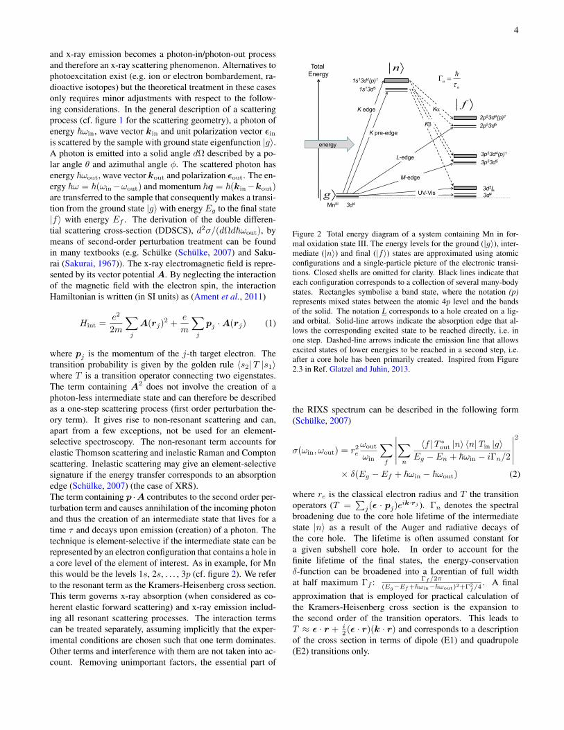
Figure 3 Simplified total energy diagram for XES. A continuum ofintermediate and final states is reached whose energies depend on thephotoelectron kinetic energy ε. Several of these pairs of states mayexist (with different n′, f ′ and ε) that need to summed up for a fulltreatment of the x-ray emission process after photo excitation.
of eV above an absorption edge and approaches a 1E3 de-
pendence. In this range, the photoelectron (described by itsenergy ε) does not interact with the remaining ion; the in-termediate and final states with their energies are written as(Ljungberg et al., 2010) 〈n| = 〈n′| 〈ε|, En = En′ + ε and〈f | = 〈f ′| 〈ε|, Ef = Ef ′ +ε (cf. figure 3). The photoelectrondoes not change its energy upon the radiative decay of the ion.One thus obtains, for each ionic intermediate and final state,n′ and f ′, an infinite number of states characterised by thekinetic energy of the photoelectron. Eq. 2 then becomes
σ(ωin, ωout) ∝∑f ′
∑n′
∫ε
∣∣∣∣ 〈f ′| 〈ε|T ∗out |ε〉 |n′〉 〈n′| 〈ε|Tin |g〉Eg − (En′ + ε) + ~ωin − iΓn/2
∣∣∣∣2× Γf/2π
(Eg − (Ef ′ + ε) + ~ωin − ~ωout)2 + Γ2f/4
(3)
We assume constant absorption and emission matrix elementsfor each n′, f ′, i.e. independent of the photoelectron kinetic
energy ε (which is justified over a small energy range), andwe obtain
σ(ωin, ωout) ∝∑f ′
∑n′
|〈f ′| 〈ε|T ∗out |ε〉 |n′〉 〈n′| 〈ε|Tin |g〉|2
×∫ε
1
(Eg − (En′ + ε) + ~ωin)2 + Γ2n/4
× Γf/2π
(Eg − (Ef ′ + ε) + ~ωin − ~ωout)2 + Γ2f/4
(4)
The integral over ε is a convolution of two Lorentzian func-tions which gives a Lorentzian as a function of ωout withwidth Γn + Γf which is the known result for non-resonantfluorescence spectroscopy. A broad energy bandwidth for theincident beam will result in a larger range of photoelectronkinetic energy but not influence the width of the convolutedLorentzian. Hence, the spectral broadening is independent ofthe incident energy bandwidth. This opens the door to ex-periments using non-monochromatic radiation with a band-width of ∆E < 100 eV (pink beam) at synchrotron radiationsources or free electron lasers (Kern et al., 2013).The spectral shape does not depend on ε as long as the sameset of intermediate states n′ is reached. This may change if theincident energy suffices to create more than one core hole (cf.Ref. Hoszowska and Dousse, 2013 and references therein).One example is the KL-edge where one incident photon cre-ates a hole in the K- and L-shell. This may significantly alterthe x-ray emission spectral shape. It is therefore important tochoose the incident energy below the edge of multi-electronexcitations, if possible.
III. APPROACHES TO THE CALCULATIONS
In this section we will present a short overview of the meth-ods currently employed to calculate the experimental spectra.The theoretical simulation is an important tool for the exper-imentalist who needs to analyse the collected spectra and toplan new experiments. We can roughly separate the variousapproaches to the calculations of inner-shell spectra into twomain philosophies, that we can refer to as: many-body atomicpicture and single-particle extended picture. They are based,respectively, on ligand field multiplet theory (LFMT) and den-sity functional theory (DFT).In LFMT one first considers a single ion and writes its wave-function as a single or linear combination of Slater determi-nants of atomic one-electron wavefunctions. The chemicalenvironment is then considered by empirically introducing thecrystal field splittings and the orbital mixing. A detailed de-scription of LFMT can be found in textbooks (De Groot andKotani, 2008; Bransden and Joachain, 1983; Figgis and Hitch-man, 2000) or topical reviews (de Groot, 2001; Griffith andOrgel, 1957; de Groot, 2005), while a tutorial-oriented de-scription of the calculations was given by van der Laan (vanDer Laan, 2006). The codes currently in use are those devel-

6
oped by Cowan (Cowan, 1968, 1981) in the sixties and ex-tended by Thole in the eighties (cf. Ref. van der Laan, 1997for a technical overview). Recently, a user friendly interface,CTM4XAS (Stavitski and de Groot, 2010), has permitted alarger community accessing such calculations. The advantageof this approach is that the core hole is explicitely taken intoaccount and multi-electron effects are calculated naturally byapplying multiplet theory. The obvious problem with this ap-proach is that the chemical environment is only consideredempirically.In the DFT-based approach, a simplified version of theSchrödinger equation is solved either for a cluster of atomscentered around the absorbing one (real space method) or us-ing periodic boundary conditions (reciprocal space method).This means that the electronic structure is calculated ab ini-tio, without the need of empirical parameters, and the resultsdepend on the level of approximation employed. Among thelarge number of presently used codes, the most common tech-niques are: multiple scattering theory (e.g. FEFF9 (Rehr et al.,2010, 2009), FDMNES (Joly, 2001; Bunau and Joly, 2009)and MXAN (Benfatto and Della Longa, 2001)), full poten-tial linearised augmented plane wave, FLAPW (e.g. WIEN2K(Schwarz and Blaha, 2003; Pardini et al., 2012)), projectoraugmented-wave method, PAW (e.g. QUANTUM-ESPRESSO(Giannozzi et al., 2009; Gougoussis et al., 2009; Bunau andCalandra, 2013), GPAW (Enkovaara et al., 2010; Ljungberget al., 2011), BIGDFT (Genovese et al., 2008)) and time-dependent DFT (e.g. ORCA (Neese, 2012; Debeer George andNeese, 2010)). The advantage in the DFT approach is thatthe theoretical framework is well established and numerousgroups work on evaluating and improving the level of the-ory, i.e. the exchange-correlation functionals or the basis sets.However, DFT is a theory to calculate the ground state elec-tronic structure which is a priori incompatible with inner-shellspectroscopy. Furthermore, in its basic implementation, DFTcalculates one-electron transitions which are insufficient whenthe inner-shell vacancy gives a pronounced perturbation ofthe electronic structure, resulting in important many-body ef-fects. These shortcomings have been addressed within DFTand considerable progress has been made (Onida and Rubio,2002).The decision on which approach is most suitable for the prob-lem at hand can be based on the degree of localization of theorbitals that are assumed to be involved in the transitions.The K absorption main edge in 3d transition metals is of-ten modeled using DFT. The pre-edge requires a mixture ofatomic and extended view and therefore only in a few favor-able cases a good understanding of the pre-edge features hasbeen achieved. The L-edges of rare earths and 5d transitionmetals require an extended approach. However, 2p to 4f tran-sitions that form the L pre-edge in rare earths are highly lo-calised and an atomic approach is very successful. The Kβmain line emission in 3d transition metals involve atomic or-bitals. Multiplet theory can therefore reproduce the spectralshape to high accuracy. In contrast, the valence-to-core linesinvolve molecular orbitals that are mainly localised on the lig-
ands and a one-electron DFT approach is therefore very suc-cesful in reproducing the spectra.It is often illuminating to apply a very simplified approach tosimulate an experimental result, as it permits assessing whatinteractions and effects are relevant. As an example, if one ne-glects interference effects, the core hole potential and multi-electron transitions, it is possible to drastically simplify theKramers-Heisenberg formula (Eq. 2) for the case of valence-to-core RIXS and obtain an expression in terms of the angularmomentum projected density of states (Jiménez-Mier et al.,1999)
σ(ωin, ωout) ∝∫ε
ρ(ε)ρ′(ε+ ωin − ωout)
(ε− ωout)2 + Γ2n/4
dε (5)
where ρ and ρ′ are, respectively, the occupied and unoccupieddensity of states, Γn the lifetime broadening of the inter-mediate state. This approach has been demonstrated validin describing the VTC-RIXS spectra of 5d transition metalsystems (Smolentsev et al., 2011; Garino et al., 2012). Asimilar approach but partly considering the core hole potentialand the radial matrix element was recently implemented inthe FEFF9 code (Kas et al., 2011).The combination of an extended picture with full multipletcalculations is the holy grail in theoretical inner-shell spec-troscopy. The progress in recent years has been impressiveto the great benefit of the experimentalists who are graduallygetting a better handle on analyzing their data (Mironeet al., 2000; Uldry et al., 2012; Mirone, 2012). A promisingmethod is to make use of maximally localised Wannierfunctions (Marzari et al., 2012) as directly obtained fromDFT calculations. If one extracts the Wannier orbitals in thebands near the Fermi level, is then possible to calculate thespectra via LFMT (Haverkort et al., 2012). However, thismethod is still an approximate solution of the problem. Amore rigorous treatement was proposed in the framework ofthe multi-channel multiple scattering (MCMS) theory (Natoliet al., 1990) (recently revised in Ref. Natoli et al., 2012). TheMCMS method has been successfully applied in simulatingthe L2,3 XAS spectra of Ca (Krüger and Natoli, 2004) andTi (Krüger, 2010) and could be easily extended to XES andRIXS.
IV. EXPERIMENTAL SET-UP
Before presenting a selection of applications of the tech-nique, we describe how a combined XAS/XES experiment isperformed on a generic synchrotron radiation beamline. Thisis schematically illustrated in figure 4. The synchrotron radia-tion is produced in the storage ring via an undulator, bendingmagnet or wiggler (source). A first collimating mirror, run intotal reflection geometry, is usually used to reduce the heatload, collimate the beam and remove the higher harmonics.The beam is then monochromatised by a double single crystalmonochromator (cryogenically cooled); typically two pairs of

7
Fe3O4
XAS
XES
topview
sideview
focusingoptics
mono- chromator(s)
phase retarder(s)
storagering
total or partial fluorescence
detector
spectrometersource
slits monitor sample
mirror
Figure 4 Schematic view (top/side) of a generic hard x-ray RIXS-dedicated beamline: optics and experimental stations (cf. description in thetext). The represented objects are not in scale and do not represent a given technical design. Right panels show an example of XAS (scanningthe incoming energy, ~ωin, top) and XES (scanning the outgoing energy, ~ωout, bottom) spectra of Fe3O4 powder obtained at the Fe K-edge.
crystals are employed: Si(111) or Si(311), giving an intrinsic(without taking into account the beam divergence) resolvingpower, E
∆E , of 7092 and 34483 (Matsushita and Hashizume,1983), respectively. The monochromatic beam is thenfocused to the sample via a focusing system, typically, twobent mirrors in Kirkpatrick-Baez geometry (Kirkpatrick andBaez, 1948), that is, working in glancing incidence (around3 mrad), one focusing horizontally and the second one,perpendicular to the previous, focusing vertically. A givennumber of slits (vertical and horizontal) is also inserted in thebeam path to clean for aberrations and reduce the divergence.In addition, the beamline optics can be complemented witha second monochromator or phase retarders. The secondmonochromator, typically a channel cut in four crystalsconfiguration (DuMond, 1937), is used to improve the energyresolution. The phase retarders (Giles et al., 1995), typicallythin diamond crystals put in diffraction conditions, permittuning the polarization of the x-ray beam. In fact, apart forhelical undulators, the x-ray beam is linearly polarised inthe orbital plane and the phase retarders are required forgenerating circularly polarised light (left and right) or linearlypolarised in the vertical plane.In the experimental station, the equipment is built around thesample stage (figure 4). The main elements consist in x-raydetectors for monitoring the incoming and transmitted beamand measuring the fluorescence emitted by the excited sam-ple. For hard x-rays, the sample environment does not requirea vacuum chamber and it is quite versatile: a goniometerpermits aligning the sample in three dimensions plus hostingadditional equipments (e.g. cryostat, furnace, magnet orchemical reactor). For bulk samples, the XAS (absorptioncoefficient, µ(~ωin)) is measured directly via the intensity ofthe incoming (Iin) and transmitted beam (Iout), according tothe Beer-Lambert law: Iout = Iine
−µ(~ωin)x, where x is thesample’s thickness. For dilute species, µ cannot be measured
directly and a secondary process (yield) has to be employed,assuming that the absorption cross section is proportional tothe number of core holes created. The secondary processescan be either the collection of the electron yield (Erbil et al.,1988) or the fluorescence yield (Jaklevic, 1977). We will nottreat the electron yield here, but focus on the fluorescenceyield (FY) because this gives access to a photon-in/photon-out spectroscopy, as XES and RIXS. Usually, the FY-XAS iscollected either without energy resolution (total FY) or withan energy dispersive solid state detector (SSD) as an array ofhigh purity germanium elements or silicon drift diodes. Forlinearly polarised synchrotron radiation (with εin along x, cf.figure 1, as in standard experiments) the Thomson (elastic),Compton and Raman (inelastic) scattering have an angulardependence of sin2(φ) + cos2(θ)cos2(φ) (cf. figure 1) whilethe fluorescence emitted by the sample is isotropic (in astandard geometry and not considering polarization effects,cf. Ref. Bianchini and Glatzel, 2012 for the full expression),thus the fluorescence detectors are usually put at 90 degreeson the polarization plane to minimise the background dueto scattering (cf. figure 4). SSD detectors permit a typicalenergy resolution of 150-300 eV ( E
∆E ≈ 50). This low energyresolution combined with a low saturation threshold is adrawback for measuring dilute species in strong absorbingmatrices as DMS/CMS. In fact, the weak signal of interest isvery often sitting on the strong background coming from thelow-energy tail of the Thompson and Compton scattering oroverlapping with the fluorescence lines of the other elementscontained in the matrix. For thin films deposited on a sub-strate, a workaround for collecting a clean fluorescence signalis to work in a combined grazing incidence and grazing exitgeometry (Maurizio et al., 2009) but this has the drawbackof fixing the experimental geometry and it is not suitablefor single crystals where it is important also to work withthe polarization axis laying out of the sample surface. An
8
increased energy resolution ( E∆E ≈ 1000) can be obtained
with charged coupled devices (Fourment et al., 2009) ormicrocalorimetric arrays (Uhlig et al., 2013) used in energyresolving mode. However, the complexity of these detectors(especially in the events reconstruction algorithms) and thevery quick saturation for calorimeters, limits their applicationon standard spectroscopy beamlines.In order to overcome these limitations and to collect XES,RIXS and HERFD-XAS, a wavelength dispersive spectrom-eter has to be employed ( E
∆E > 5000). For hard x-rays,this means that Bragg’s diffraction over an analyser crystalis employed to monochromatise the emitted fluorescencefrom the sample (Rowland’s circle geometry). Among all thepossible diffraction geometries (Jalal and Golamreza, 2011),two main configurations are currently in use at synchrotronfacilities: the point-to-point Johann (Johann, 1931) and thedispersive Von Hamos (v. Hámos, 1933). For both, the basicprinciple is that the source (sample), the diffractor (analysercrystal) and the image (detector) are on the Rowland cir-cle. The first class uses spherically bent crystals (Verbeniet al., 2005) in combination with one-dimension detector;the energy selection is performed by scanning the crystalBragg’s angle and the detector over the Rowland circle. Inthe second class, a cylindrically bent crystal is combinedwith a position-sensitive detector; the energy dispersion isobtained without moving the crystal and by collecting thedifferent areas of the detector. Without going into the detailsof the advantages and disadvantages of each configuration,good performances are obtained with an increased number ofspherically bent crystals (to overcome the small solid anglecollected, ≈ 0.03 sr per crystal) working at Bragg’ anglesclose to 90 deg. As few examples of currently availableinstruments, there are those dedicated to XRS (Verbeniet al., 2009; Sokaras et al., 2012), medium-resolution RIXS(Glatzel et al., 2009; Kleymenov et al., 2011; Llorens et al.,2012; Sokaras et al., 2013) and single-shot XES (Szlachetkoet al., 2012; Alonso-Mori et al., 2012).
V. THE RIXS PLANE AND SHARPENING EFFECTS
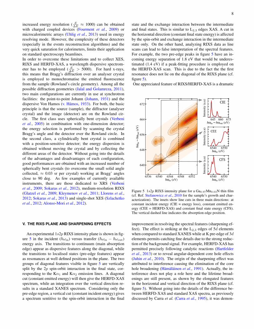
An experimental 1s2p RIXS intensity plane is shown in fig-ure 5 in the incident (~ωin) versus transfer (~ωin − ~ωout)energy axis. The transitions to continuum (main absorptionedge) appear as dispersive features along the diagonal, whilethe transitions to localised states (pre-edge features) appearas resonances at well defined positions in the plane. The twogroups of diagonal features visible in figure 5 are verticallysplit by the 2p spin-orbit interaction in the final state, cor-responding to the Kα1 and Kα2 emission lines. A diagonalcut (constant emitted energy) will then give the HERFD-XASspectrum, while an integration over the vertical direction re-sults in a standard XANES spectrum. Considering only thepre-edge region, a vertical cut (constant incident energy) givesa spectrum sentitive to the spin-orbit interaction in the final
state and the exchange interaction between the intermediateand final states. This is similar to L2,3 edges XAS. A cut inthe horizontal direction (constant final state energy) is affectedby the spin-orbit and exchange interaction in the intermediatestate only. On the other hand, analyzing RIXS data as linescans can lead to false interpretation of the spectral features.For example, the two pre-edge peaks in figure 5 have an in-coming energy separation of 1.8 eV that would be underes-timated (1.4 eV) if a peak-fitting procedure is employed onthe HERFD-XAS scan. This is due to the fact the the firstresonance does not lie on the diagonal of the RIXS plane (cf.figure 5).One appreciated feature of RIXS/HERFD-XAS is a dramatic
6536 6540 6544 6548 6552hωin (eV)
640
648
656
664
672
hωin−hω
out(eV)
645 660 675hωin− hωout (eV)
Intensity
(a.u)
6540 6550hωin (eV)
Intensity
(a.u)
6540 6550hωin (eV)
Intensity
(a.u)
CIE
CEE
CFS
Figure 5 1s2p RIXS intensity plane for a Ga0.97Mn0.03N thin film(cf. Ref. Stefanowicz et al., 2010 for the sample’s growth and char-acterization). The insets show line cuts in three main directions: atconstant incident energy (CIE = energy loss), constant emitted en-ergy (CEE = HERFD-XAS) and constant final state energy (CFS).The vertical dashed line indicates the absorption edge position.
improvement in resolving the spectral features (sharpening ef-fect). The effect is striking at the L2,3 edges of 5d elementswhen compared to standard XANES while at K pre-edge of 3delements permits catching fine details due to the strong reduc-tion of the background signal. For example, HERFD-XAS haspermitted precisely following catalytic reactions (Hartfelderet al., 2013) or to reveal angular-dependent core hole effects(Juhin et al., 2010). The origin of the sharpening effect wasattributed to interference causing the elimination of the corehole broadening (Hämäläinen et al., 1991). Actually, the in-terference does not play a role here and the lifetime broad-enings are still present, as shown by the elongated featuresin the horizontal and vertical direction of the RIXS plane (cf.figure 5). Without going into the details of the difference be-tween HERFD-XAS and standard XAS spectra, as previouslydiscussed by Carra et al. (Carra et al., 1995), it was demon-

9
strated that the improved resolution of the experimental spec-tra can be reproduced by an apparent broadening (de Grootet al., 2002)
Γexp ≈1√
(1/Γn)2 + (1/Γf )2(6)
where the intermediate (Γn) and final (Γf ) core hole lifetimebroadenings are taken into account.
VI. VALENCE STATES SENSITIVITY OF KFLUORESCENCE LINES
The macroscopic properties of semiconductors (e.g. trans-port, magnetism) are driven by impurities (defects) located atvalence states. Accessing the information of such states via abulk probe, permits then having a detailed description of thematerial under study. XES can probe valence electrons eitherindirectly or directly, by selecting the yield for different transi-tions. If one collects core-to-core (ctc) transitions, the valenceelectrons are probed indirectly, while directly for valence-to-core (vtc). The selectivity to the electronic structure of thevalence shell in CTC-XES originates from screening effects(the core levels energy is affected by the modified nuclear po-tential) and multiplet structure (the spin and orbital angularmomentum of the core hole strongly couple to the valenceelectrons). The screening dominates for light elements as, forexample, the Kα XES of S (Alonso Mori et al., 2009), whilethe multiplet structure dominates in the case of the K fluores-cence lines of 3d TMs.
A XES spectrum is given in figure 6 for Cr in Cr2O3. The
Nor
mal
ized
inte
nsi
ty (
arb
. un
its)
Emitted energy (eV)
1s
2p3pVBCB
Kα2
Kα1
Kβ''
Kβ2,5
Kβ1,3
Kβ'
Figure 6 XES spectrum of Cr2O3 showing the Cr K fluorescencelines (blue): CTC-Kα, CTC-Kβ and VTC-Kβ. In the plots the inten-sity is normalised to the Kα1 maximum; the insets show an expandedview for CTC-Kβ and VTC-Kβ. The top schemes show the origin ofthe transitions after photoionization in a simplified one-electron pic-ture. Black lines indicate core states (1s, 2p, 3p), while the rectaglessymbolise the valence and conduction bands (VB and CB).
most intense lines are the Kα1 (K-L3, 2p3/2 → 1s) and Kα2
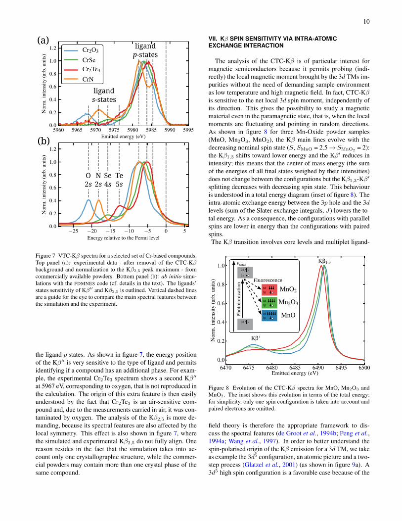
(K-L2, 2p1/2 → 1s), where the 2p level is splitted by thestrong spin-orbit interaction. With ≈ 10-times smaller inten-sity are visible the CTC-Kβ lines (K-M2,3, 3p→ 1s), called(Tsutsumi, 1959) Kβ1,3 (main peak) and Kβ′ (broad shoulderat lower emitted energy). Finally, the VTC-Kβ lines appearon the tail of the main lines with roughly 200-times smallerintensity, those are called Kβ2,5 and Kβ′′. The origin and in-formation content of CTC-Kβ lines is given later in § VII,while here we focus first on VTC-Kβ lines.The VTC-Kβ arise from transitions from occupied orbitalsa few eV below the Fermi level (the valence band), that is,from orbital mixed metal-ligand states of metal p-characterto 1s. For this reason, VTC-Kβ is strongly sensitive to ligandspecies and has been employed in chemistry to distinguish be-tween ligands of light elements (Bergmann et al., 1999; Sa-fonov et al., 2006; Eeckhout et al., 2009; Lancaster et al.,2011) (e.g. C, N, O, S). In addition, by making use of theXES polarization dependence (Glatzel and Bergmann, 2005)is possible to study the orientation of the lingands. For exam-ple, Bergmann et al. (Bergmann et al., 2002) studied a Mnnitrido coordination complex in C4v symmetry with five CNand one N ligand at a very short distance (1.5 Å). The signalarising from the nitrido molecular orbitals was almost com-pletely suppressed by orienting the Mn-nitrido bond in thedirection of kout, i.e. towards the crystal analyser. Anotheradvantage of VTC-Kβ is the possibility to easily calculatethe transitions with a molecular-orbital approach: from earlyatomic (Best, 1966) to recent DFT methods (Pollock and De-Beer, 2011; Gallo et al., 2011; Vila et al., 2011). These worksdemonstate that the Kβ′′ and Kβ2,5 are mainly sensitive, re-spectively, to the ligand s and p states. The Kβ2,5 has also astrong dependece on the metal’s local symmetry (Smolentsevet al., 2009; Gallo et al., 2013) (e.g. TD vs Oh). For a morerigorous treatement, the interested reader can refer to a recenttopical review (Gallo and Glatzel, 2014).
In DMS, one application of VTC-Kβ is in the study of theinteraction of shallow dopants with the metal site. For exam-ple, in Zn1−xCrxTe co-doped with N (Kuroda et al., 2007),where N is an acceptor (brings holes in the valence band),by measuring the Cr VTC-Kβ it is possible to detect whenN interacts with Cr via the clear signature of N 2s levels inthe Cr Kβ′′. This is illustrated in figure 7 where we show aselection of VTC-Kβ spectra for commercially available Cr-based powder compounds compared with the ab initio simula-tions (FDMNES code (Bunau and Joly, 2009)). Standard crys-tal structures (retrieved from the “Inorganic Crystal StructureDatabase”, FIZ Karlsruhe) are used as input in the calcula-tions, conducted in real space with a muffin-tin approxima-tion and the Hedin-Lundqvist exchange-correlation potential.To compare with the experiment, the calculated Fermi levelsare arbitrarily shifted and the spectra are convoluted with aconstant Lorentian broadening of 2.68 eV. The origin of thefeatures is then attributed by selecting the projected densityof states on the ligands that overlaps with the metal p one(not shown). This confirms previous works, that is, the Kβ′′
mainly comes from the ligand s states, while the Kβ2,5 is from
10
O2s
Te5s
N2s
Se4s
ligands-states
ligandp-states
(a)
(b)
Figure 7 VTC-Kβ spectra for a selected set of Cr-based compounds.Top panel (a): experimental data - after removal of the CTC-Kβbackground and normalization to the Kβ2,5 peak maximum - fromcommercially available powders. Bottom panel (b): ab initio simu-lations with the FDMNES code (cf. details in the text). The ligands’states sensitivity of Kβ′′ and Kβ2,5 is outlined. Vertical dashed linesare a guide for the eye to compare the main spectral features betweenthe simulation and the experiment.
the ligand p states. As shown in figure 7, the energy positionof the Kβ′′ is very sensitive to the type of ligand and permitsidentifying if a compound has an additional phase. For exam-ple, the experimental Cr2Te3 spectrum shows a second Kβ′′
at 5967 eV, corresponding to oxygen, that is not reproduced inthe calculation. The origin of this extra feature is then easilyunderstood by the fact that Cr2Te3 is an air-sensitive com-pound and, due to the measurements carried in air, it was con-taminated by oxygen. The analysis of the Kβ2,5 is more de-manding, because its spectral features are also affected by thelocal symmetry. This effect is also shown in figure 7, wherethe simulated and experimental Kβ2,5 do not fully align. Onereason resides in the fact that the simulation takes into ac-count only one crystallographic structure, while the commer-cial powders may contain more than one crystal phase of thesame compound.
VII. Kβ SPIN SENSITIVITY VIA INTRA-ATOMICEXCHANGE INTERACTION
The analysis of the CTC-Kβ is of particular interest formagnetic semiconductors because it permits probing (indi-rectly) the local magnetic moment brought by the 3d TMs im-purities without the need of demanding sample environmentas low temperature and high magnetic field. In fact, CTC-Kβis sensitive to the net local 3d spin moment, independently ofits direction. This gives the possibility to study a magneticmaterial even in the paramagnetic state, that is, when the localmoments are fluctuating and pointing in random directions.As shown in figure 8 for three Mn-Oxide powder samples(MnO, Mn2O3, MnO2), the Kβ main lines evolve with thedecreasing nominal spin state (S, SMnO = 2.5→ SMnO2
= 2):the Kβ1,3 shifts toward lower energy and the Kβ′ reduces inintensity; this means that the center of mass energy (the sumof the energies of all final states weighed by their intensities)does not change between the configurations but the Kβ1,3-Kβ′
splitting decreases with decreasing spin state. This behaviouris understood in a total energy diagram (inset of figure 8). Theintra-atomic exchange energy between the 3p hole and the 3dlevels (sum of the Slater exchange integrals, J) lowers the to-tal energy. As a consequence, the configurations with parallelspins are lower in energy than the configurations with pairedspins.The Kβ transition involves core levels and multiplet ligand-
Fluorescence
Photoion
ization
1s
μ3d
μ3d
3d
3p
3d
3p
3d
3p
Etotal
Figure 8 Evolution of the CTC-Kβ spectra for MnO, Mn2O3 andMnO2. The inset shows this evolution in terms of the total energy;for simplicity, only one spin configuration is taken into account andpaired electrons are omitted.
field theory is therefore the appropriate framework to dis-cuss the spectral features (de Groot et al., 1994b; Peng et al.,1994a; Wang et al., 1997). In order to better understand thespin-polarised origin of the Kβ emission for a 3d TM, we takeas example the 3d5 configuration, an atomic picture and a two-step process (Glatzel et al., 2001) (as shown in figure 9a). A3d5 high spin configuration is a favorable case because of the

11
absence of an orbital angular momentum in the ground state.Hund’s rule dictates that all spins are aligned, giving the 6Sground state spin-orbit term. Photoionization then excites thesystem to the 1s3d5+εp (5,7S) intermediate states. The 7Sterm can only decay into the 7P, while the 5S one decays intoall interacting 5P states (where symmetry mixing is impor-tant). In consequence, the Kβ′ originates almost 100% fromspin-up transitions and the Kβ1,3 primarly from spin-down.This result is exemplified in figure 9b via a one-electron pic-ture of the final state. In Ref. Wang et al., 1997, the strongspin selectivity was demonstrated valid also when the atom isinserted in a crystal field. In fact, neglecting orbital mixing,the Kβ lines do not depend on the fine structure in the valenceshell (e.g. crystal field splitting) as long a the spin state doesnot change. On the other hand, a strong crystal field splittingmay result in a low spin configuration which will change theKβ line shape (Badro et al., 2003). These considerations arevalid for Oh symmetry. For TD symmetry, the strong spinpolarization is still present because the crystal field splitting,10Dq, is simply inverted between the two symmetries. In ad-dition, the absence of inversion symmetry (in contrast to Oh)results in strong pd mixing. Including orbital mixing in thetheoretical description, may find that the 3p3d exchange in-teraction changes owing to the mixing and thus the shape ofKβ lines varies. In conclusion, the spin selectivity is con-served and it is employed to record spin-selective XAS (cf.§ VII.A), while the spectral features change and the methodsto take them into account are discussed in the following.
To perform quantitative analysis of the CTC-Kβ, the first
7P
5P
5P
5,7S
6S
Tot
al e
ner
gy
3d5 1s3d5+εp 3p53d5
Ph
otoi
oniz
atio
n
Kβ
fluorescen
ceKβ' Kβ1,3
3d
3p
1s
(a) (b)
Figure 9 Kβ emission process after photoionization illustrated for a3d5 case. Left panel (a): atomic multiplet theory. Right panel (b):simplified one-electron picture (not in energy scale) where pairedelectrons and the spin flipping in Kβ1,3 are omitted for clarity. Adetailed description is given in the text.
method is to approximate the energy separation and the inten-sity ratio between Kβ1,3 and Kβ′ by ∆E = J(2S + 1) andI ′/I1,3 = S/(S+1) (Tsutsumi et al., 1976). This approxima-tion is found to reproduce fairly well the experimental resultsif a peak fitting procedure is employed (Gamblin and Urch,2001; Torres Deluigi et al., 2006; Bergmann et al., 1998). Onthe other hand, a peak fitting procedure is prone to errors in theextraction of the peaks positions and arbitrary in the choice ofthe number and form of the fitted functions. To overcome the
problem of linking the data analysis to a theoretical approxi-mation, fully experimental data reduction methods were put inplace. The first attempt was to use the first moment energy ofthe Kβ1,3 (Glatzel et al., 2001; Messinger et al., 2001) (〈E〉),defined as the energy average weighted by the spectrum inten-sity: 〈E〉 =
∑j(EjIj)/
∑j Ij . Recently, another and more
accurate procedure was proposed (Vankó et al., 2006a,b). It isbased on the integrated absolute difference (IAD) of spectra
IADi =
∫ E2
E1
∣∣σXESi (E)− σXES
0 (E)∣∣ dE (7)
where the XES spectrum σ0 is taken as reference (IAD0 = 0)and σi is the spectrum for which the IAD value is determined.Often the IAD values are determined versus a given parameterwithin a series (e.g. pressure, temperature, concentration, dop-ing) but the method can be applied to any spectra. It is basedon the differences in the whole spectral range and results ina more robust procedure, especially when dealing with weakmoments. It was successfully applied to determine the evolu-tion of the local magnetic moment (S) in iron-based supercon-ductors (Gretarsson et al., 2011; Chen et al., 2011; Simonelliet al., 2012) or in strongly correlated oxides (Lengsdorf et al.,2007; Sikora et al., 2008; Herrero-Martín et al., 2010). To il-
MnOMn2O3
MnIIO
MnIII2O3
MnIVO2
K2MnVIO4
Figure 10 IAD analysis for a series of Mn-Oxides with respect toMnO. The inset shows how the IAD is obtained for Mn2O3.
lustrate the method in practice, the IAD analysis for a seriesof polycrystalline Mn-Oxides (commercially available pow-ders) is shown in figure 10. The IAD values of the normalisedspectra are obtained using MnO as reference (IADMnO = 0)and are related to the nominal spin state, assuming a ionic ap-proximation and a high-spin scenario. Subsequently, a linearfit permits obtaining a relative calibration that accounts forall possible effects: changes in oxidation state, bond lengthsand angles, site symmetry, energy shifts during the experi-ment. By taking into account all these effects, the error baron the IAD values is comparable with the size of the sym-bols of figure 10. This makes such analysis very accurate andreproducible. Once the IAD values are calibrated on modelcompounds, it is possible to follow the evolution on real sam-ples. For DMS/CMS one usually wants to follow the evolu-tion versus the magnetic dopant concentration or the ratio with

12
shallow impurities in the case of co-doping.To overcome the crude ionic approximation and to take intoaccount the covalent bonds in a material (charge transfer),better results are obtained if the IAD values are compared orcalibrated to an effective local spin moment, Seff , defined as(Limandri et al., 2010)
Seff =1
2
(ρ↑A,l − ρ
↓A,l
)(8)
where ρ↑(↓)A,l is the calculated spin density (charge) on the atomA and projected on the orbital angular momentum l. Theprojection over l permits having an effective quantity com-parable to the spectroscopic measurement. In fact, althoughthe charge of an atom in a crystal or molecule is not a goodquantum mechanical observable (Parr et al., 2005; Matta andBader, 2006), the inner-shell spectroscopist is tempted to as-sign atomic properties. Many quantum chemical approachesexist (Gross et al., 2002), but in DFT the standard methods toperform a population analysis are those introduced by Mul-liken (Mulliken, 1955), Löwdin (Löwdin, 1950) and Bader(Bader, 1991). In the Mulliken or Löwdin analysis the chargesare equally divided between two atoms of a bond; this has theadvantage of simplicity. A different approach is followed forthe Bader populations: the electron densities are integratedin a volume defined by the gradient of the electronic densityfunction. This scheme usually gives the best results.
The combination of the IAD analysis with Seff calculated
(0)
(1)
(2)(3)(4)
Figure 11 Nominal spin (left, red) extracted by calibrating theIAD values via a ionic approximation, compared to Seff calcu-lated via Bader’s population analysis (right, blue). The gray pan-els (0 – 4) show the calculated polarization on Mn 3d levels (vio-let isosurface) over a ball-and-stick local atomic representation ofMnN4(MgN4)0...4 substitutional complexes. The surrounding GaNlattice has been removed for clarity.
ab initio using DFT has been recently applied in the studyof Mn-Mg substitutional complexes in Ga1−x−yMnxMgyN(Devillers et al., 2012). As shown in figure 11, the IAD are
employed to follow the evolution of the Mn spin state as afunction of the ratio between the Mg and Mn concentration inGaN. By calibrating the IAD values to the Mn-Oxides refer-ence compounds using a ionic approximation, it is possible toextract a nominal spin state. This is then compared to Seff cal-culated via DFT. Both evolve in the same way and differ onlyby a rigid shift (≈ 0.2 in this case). This shift originates fromthe ionic approximation used to calibrate the IADs. In fact, thecorrect procedure to extract a better absolute measurement ofS is to calibrate the IAD via the Bader analysis performed alsoon the model compounds. By doing so, one finds SMnO = 2.2,in perfect agreement with Seff calculated for Mg/Mn = 0 infigure 11. This confirms that the IAD analysis with an ab ini-tio Seff is accurate in following the evolution of the local spinmoment.As described for VTC-Kβ, also in CTC-Kβ it is possibleto make use of the polarization dependence. For example,Herrero-Martin et al. (Herrero-Martín et al., 2010) studiedthe spin distribution in La1−xSrxMnO4. They found that in-creasing the number of holes (i.e. increasing x) changes thetotal charge (and spin) on Mn very little, but the tetragonaldistortion, that is greatly reduced when going from x = 0 tox = 0.5, causes an anisotropic spin distribution that also dis-appears upon hole doping.
A. Spin-selective XAS
Spin-selective XAS was first exploited by Hämäläinen andco-workers (Hämäläinen et al., 1992) and then describedvia ligand-field multiplet theory (Peng et al., 1994a,b).This technique is based on the strong spin polarization ofCTC-Kβ emission lines (as previously described in § VII): bycollecting a HERFD-XAS spectrum tuning the spectrometerto the Kβ1,3 and Kβ′, it is possible to select, respectively,the transitions to the spin down and spin up empty densityof states (in a one-electron picture). We underline that thespin-selectivity in this technique arises only from the Kβspectrum, that is, the spin has a local internal reference thatdoes not change in energy for a change in the direction of thespin moment. With respect to XMCD, circularly polarisedlight and an external magnetic field (external reference) arenot required. The link between the two techniques resides inthe energy dependence of the Fano factor (de Groot et al.,1995).
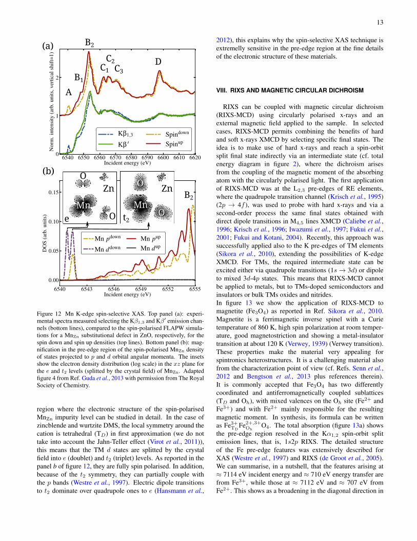
An example of application of this technique to the charac-terization of magnetic semiconductors was reported recently(Guda et al., 2013). The Mn K-edge HERFD-XAS spectraof ZnO/Zn1−xMnxO core/shell nano-wires were measured atKβ1,3 and Kβ′, then compared to ab initio DFT calculationsusing a FLAPW approximation. As shown in figure 12,the spectral features A, B1,2, C1...3 and D are reproducedby the theory (panel a), in agreement between the twospin-polarizations. This agreement was obtained using aMn defect substitutional of Zn (MnZn) in a ZnO relaxedsupercell. Of particular interest for DMS is the pre-edge
13
Mn Mn
O
O O
OZn Zn
e t2
A
B1
B2
C1
C2C3
B2
D
(a)
(b)
Figure 12 Mn K-edge spin-selective XAS. Top panel (a): experi-mental spectra measured selecting the Kβ1,3 and Kβ′ emission chan-nels (bottom lines), compared to the spin-polarised FLAPW simula-tions for a MnZn substitutional defect in ZnO, respectively, for thespin down and spin up densities (top lines). Bottom panel (b): mag-nification in the pre-edge region of the spin-polarised MnZn densityof states projected to p and d orbital angular momenta. The insetsshow the electron density distribution (log scale) in the xz plane forthe e and t2 levels (splitted by the crystal field) of MnZn. Adaptedfigure 4 from Ref. Guda et al., 2013 with permission from The RoyalSociety of Chemistry.
region where the electronic structure of the spin-polarisedMnZn impurity level can be studied in detail. In the case ofzincblende and wurtzite DMS, the local symmetry around thecation is tetrahedral (TD) in first approximation (we do nottake into account the Jahn-Teller effect (Virot et al., 2011)),this means that the TM d states are splitted by the crystalfield into e (doublet) and t2 (triplet) levels. As reported in thepanel b of figure 12, they are fully spin polarised. In addition,because of the t2 symmetry, they can partially couple withthe p bands (Westre et al., 1997). Electric dipole transitionsto t2 dominate over quadrupole ones to e (Hansmann et al.,
2012), this explains why the spin-selective XAS technique isextremelly sensitive in the pre-edge region at the fine detailsof the electronic structure of these materials.
VIII. RIXS AND MAGNETIC CIRCULAR DICHROISM
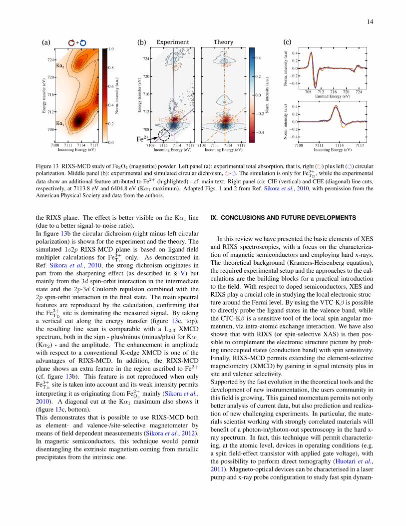
RIXS can be coupled with magnetic circular dichroism(RIXS-MCD) using circularly polarised x-rays and anexternal magnetic field applied to the sample. In selectedcases, RIXS-MCD permits combining the benefits of hardand soft x-rays XMCD by selecting specific final states. Theidea is to make use of hard x-rays and reach a spin-orbitsplit final state indirectly via an intermediate state (cf. totalenergy diagram in figure 2), where the dichroism arisesfrom the coupling of the magnetic moment of the absorbingatom with the circularly polarised light. The first applicationof RIXS-MCD was at the L2,3 pre-edges of RE elements,where the quadrupole transition channel (Krisch et al., 1995)(2p → 4f ), was used to probe with hard x-rays and via asecond-order process the same final states obtained withdirect dipole transitions in M4,5 lines XMCD (Caliebe et al.,1996; Krisch et al., 1996; Iwazumi et al., 1997; Fukui et al.,2001; Fukui and Kotani, 2004). Recently, this approach wassuccessfully applied also to the K pre-edges of TM elements(Sikora et al., 2010), extending the possibilities of K-edgeXMCD. For TMs, the required intermediate state can beexcited either via quadrupole transitions (1s→ 3d) or dipoleto mixed 3d-4p states. This means that RIXS-MCD cannotbe applied to metals, but to TMs-doped semiconductors andinsulators or bulk TMs oxides and nitrides.In figure 13 we show the application of RIXS-MCD tomagnetite (Fe3O4) as reported in Ref. Sikora et al., 2010.Magnetite is a ferrimagnetic inverse spinel with a Curietemperature of 860 K, high spin polarization at room temper-ature, good magnetostriction and showing a metal-insulatortransition at about 120 K (Verwey, 1939) (Verwey transition).These properties make the material very appealing forspintronics heterostructures. It is a challenging material alsofrom the characterization point of view (cf. Refs. Senn et al.,2012 and Bengtson et al., 2013 plus references therein).It is commonly accepted that Fe3O4 has two differentlycoordinated and antiferromagnetically coupled sublattices(TD and Oh), with mixed valences on the Oh site (Fe2+ andFe3+) and with Fe2+ mainly responsible for the resultingmagnetic moment. In synthesis, its formula can be writtenas Fe3+
TDFe2+,3+
OhO4. The total absorption (figure 13a) shows
the pre-edge region resolved in the Kα1,2 spin-orbit splitemission lines, that is, 1s2p RIXS. The detailed structureof the Fe pre-edge features was extensively described forXAS (Westre et al., 1997) and RIXS (de Groot et al., 2005).We can summarise, in a nutshell, that the features arising at≈ 7114 eV incident energy and ≈ 710 eV energy transfer arefrom Fe3+, while those at ≈ 7112 eV and ≈ 707 eV fromFe2+. This shows as a broadening in the diagonal direction in
14
(a) +
Kα1
Kα2
(c)(b)
Fe2+
Experiment Theory
Figure 13 RIXS-MCD study of Fe3O4 (magnetite) powder. Left panel (a): experimental total absorption, that is, right () plus left () circularpolarization. Middle panel (b): experimental and simulated circular dichroism, -. The simulation is only for Fe3+
TD, while the experimental
data show an additional feature attributed to Fe2+ (highlighted) - cf. main text. Right panel (c): CIE (vertical) and CEE (diagonal) line cuts,respectively, at 7113.8 eV and 6404.8 eV (Kα1 maximum). Adapted Figs. 1 and 2 from Ref. Sikora et al., 2010, with permission from theAmerican Physical Society and data from the authors.
the RIXS plane. The effect is better visible on the Kα1 line(due to a better signal-to-noise ratio).In figure 13b the circular dichroism (right minus left circularpolarization) is shown for the experiment and the theory. Thesimulated 1s2p RIXS-MCD plane is based on ligand-fieldmultiplet calculations for Fe3+
TDonly. As demonstrated in
Ref. Sikora et al., 2010, the strong dichroism originates inpart from the sharpening effect (as described in § V) butmainly from the 3d spin-orbit interaction in the intermediatestate and the 2p-3d Coulomb repulsion combined with the2p spin-orbit interaction in the final state. The main spectralfeatures are reproduced by the calculation, confirming thatthe Fe3+
TDsite is dominating the measured signal. By taking
a vertical cut along the energy transfer (figure 13c, top),the resulting line scan is comparable with a L2,3 XMCDspectrum, both in the sign - plus/minus (minus/plus) for Kα1
(Kα2) - and the amplitude. The enhancement in amplitudewith respect to a conventional K-edge XMCD is one of theadvantages of RIXS-MCD. In addition, the RIXS-MCDplane shows an extra feature in the region ascribed to Fe2+
(cf. figure 13b). This feature is not reproduced when onlyFe3+
TDsite is taken into account and its weak intensity permits
interpreting it as originating from Fe2+Oh
mainly (Sikora et al.,2010). A diagonal cut at the Kα1 maximum also shows it(figure 13c, bottom).This demonstrates that is possible to use RIXS-MCD bothas element- and valence-/site-selective magnetometer bymeans of field dependent measurements (Sikora et al., 2012).In magnetic semiconductors, this technique would permitdisentangling the extrinsic magnetism coming from metallicprecipitates from the intrinsic one.
IX. CONCLUSIONS AND FUTURE DEVELOPMENTS
In this review we have presented the basic elements of XESand RIXS spectroscopies, with a focus on the characteriza-tion of magnetic semiconductors and employing hard x-rays.The theoretical background (Kramers-Heisenberg equation),the required experimental setup and the approaches to the cal-culations are the building blocks for a practical introductionto the field. With respect to doped semiconductors, XES andRIXS play a crucial role in studying the local electronic struc-ture around the Fermi level. By using the VTC-Kβ is possibleto directly probe the ligand states in the valence band, whilethe CTC-Kβ is a sensitive tool of the local spin angular mo-mentum, via intra-atomic exchange interaction. We have alsoshown that with RIXS (or spin-selective XAS) is then pos-sible to complement the electronic structure picture by prob-ing unoccupied states (conduction band) with spin sensitivity.Finally, RIXS-MCD permits extending the element-selectivemagnetometry (XMCD) by gaining in signal intensity plus insite and valence selectivity.Supported by the fast evolution in the theoretical tools and thedevelopment of new instrumentation, the users community inthis field is growing. This gained momentum permits not onlybetter analysis of current data, but also prediction and realiza-tion of new challenging experiments. In particular, the mate-rials scientist working with strongly correlated materials willbenefit of a photon-in/photon-out spectroscopy in the hard x-ray spectrum. In fact, this technique will permit characteriz-ing, at the atomic level, devices in operating conditions (e.g.a spin field-effect transistor with applied gate voltage), withthe possibility to perform direct tomography (Huotari et al.,2011). Magneto-optical devices can be characterised in a laserpump and x-ray probe configuration to study fast spin dynam-
15
ics as spin-orbit interaction (Boeglin et al., 2010) or spin statetransitions (Vankó et al., 2013).RIXS experiments require the high brilliance of third gener-ation synchrotron radiation sources or even x-ray free elec-tron lasers, that is, high photon flux with small divergence andsmall energy bandwidth. However, XES is a powerful toolwhich can be accessible also outside large scale facilities. Infact, the advantage of XES is that it can be performed witha pink beam. This permits adapting an XES instrument onany synchrotron radiation beamline (e.g. standard XAS, x-raydiffraction, imaging) or on a laboratory x-ray tube. For ex-ample, one can take the case of measuring Mn CTC-Kβ on aGa0.97Mn0.03N thin film (dilute material in a strong absorb-ing matrix). By a simple comparison only on the incomingphoton flux, assuming 109 ph/s (e.g. from a rotating anode x-ray tube) one would get ≈ 10 counts/s on the Mn CTC-Kβmaximum. Considering the very low background of a point-to-point spectrometer, a spectrum with a reasonable signal tonoise ratio is obtained in one day of measurements.
ACKNOWLEDGMENTS
We gratefully acknowledge the European Synchrotron Ra-diation Facility for providing synchrotron radiation via inhouse research projects. M.R. would like to thank M. Sikora,E. Gallo and N. Gonzalez Szwacki for fruitiful discussions.
REFERENCES
T. Dietl, Nat. Mater. 9, 965 (2010).T. Dietl and H. Ohno, http://arxiv.org/abs/1307.3429 (2013).J. M. D. Coey and S. Sanvito, J. Phys. D. Appl. Phys. 37, 988 (2004).S. Datta and B. Das, Appl. Phys. Lett. 56, 665 (1990).G. Schmidt, D. Ferrand, L. Molenkamp, A. Filip, and B. van Wees,
Phys. Rev. B 62, R4790 (2000).M. Opel, J. Phys. D. Appl. Phys. 45, 033001 (2012).M. Bibes, J. E. Villegas, and A. Barthélémy, Adv. Phys. 60, 5 (2011).D. D. Awschalom, L. C. Bassett, A. S. Dzurak, E. L. Hu, and J. R.
Petta, Science 339, 1174 (2013).P. M. Koenraad and M. E. Flatté, Nat. Mater. 10, 91 (2011).R. E. George, J. P. Edwards, and A. Ardavan, Phys. Rev. Lett. 110,
027601 (2013).R. Jansen, Nat. Mater. 12, 779 (2013).B. Endres, M. Ciorga, M. Schmid, M. Utz, D. Bougeard, D. Weiss,
G. Bayreuther, and C. H. Back, Nat. Commun. 4, 2068 (2013).J. Sinova and I. Žutic, Nat. Mater. 11, 368 (2012).A. Bonanni and T. Dietl, Chem. Soc. Rev. 39, 528 (2010).K. Sato, L. Bergqvist, J. Kudrnovský, P. H. Dederichs, O. Eriksson,
I. Turek, B. Sanyal, G. Bouzerar, H. Katayama-Yoshida, V. A.Dinh, T. Fukushima, H. Kizaki, and R. Zeller, Rev. Mod. Phys.82, 1633 (2010).
A. Zunger, S. Lany, and H. Raebiger, Physics (College. Park. Md).3, 53 (2010).
P. A. Lee, P. H. Citrin, P. Eisenberger, and B. M. Kincaid, Rev. Mod.Phys. 53, 769 (1981).
J. J. Rehr, Rev. Mod. Phys. 72, 621 (2000).F. Boscherini, in Charact. Semicond. Heterostruct. Nanostructures,
edited by C. Lamberti (Elsevier, 2008) Chap. 9, pp. 289–330.
M. Rovezzi, Study of the local order around magnetic impuritiesin semiconductors for spintronics, Phd thesis, Joseph Fourier -Grenoble I (2009).
F. D’Acapito, Semicond. Sci. Technol. 26, 064004 (2011).L. Mino, G. Agostini, E. Borfecchia, D. Gianolio, A. Piovano,
E. Gallo, and C. Lamberti, J. Phys. D. Appl. Phys. 46, 423001(2013).
J. Stöhr, J. Magn. Magn. Mater. 200, 470 (1999).M. Sawicki, W. Stefanowicz, and A. Ney, Semicond. Sci. Technol.
26, 064006 (2011).Z. Wilamowski, M. Solnica, E. Michaluk, M. Havlicek, and
W. Jantsch, Semicond. Sci. Technol. 26, 064009 (2011).C. Brouder, J. Phys. Condens. Matter 2, 701 (1990).A. Ney, M. Opel, T. C. Kaspar, V. Ney, S. Ye, K. Ollefs, T. Kam-
mermeier, S. Bauer, K.-W. Nielsen, S. T. B. Goennenwein, M. H.Engelhard, S. Zhou, K. Potzger, J. Simon, W. Mader, S. M. Heald,J. C. Cezar, F. Wilhelm, A. Rogalev, R. Gross, and S. A. Cham-bers, New J. Phys. 12, 013020 (2010).
B. Thole, P. Carra, F. Sette, and G. van der Laan, Phys. Rev. Lett.68, 1943 (1992).
P. Carra, B. Thole, M. Altarelli, and X. Wang, Phys. Rev. Lett. 70,694 (1993).
F. de Groot, M. Arrio, P. Sainctavit, C. Cartier, and C. Chen, SolidState Commun. 92, 991 (1994a).
R. Kurian, K. Kunnus, P. Wernet, S. M. Butorin, P. Glatzel, andF. M. F. de Groot, J. Phys. Condens. Matter 24, 452201 (2012).
A. J. Achkar, T. Z. Regier, H. Wadati, Y.-J. Kim, H. Zhang, andD. G. Hawthorn, Phys. Rev. B 83, 081106 (2011a).
A. J. Achkar, T. Z. Regier, E. J. Monkman, K. M. Shen, and D. G.Hawthorn, Sci. Rep. 1, 182 (2011b).
P. Carra, M. Fabrizio, and B. Thole, Phys. Rev. Lett. 74, 3700 (1995).T. E. Westre, P. Kennepohl, J. G. DeWitt, B. Hedman, K. O. Hodg-
son, and E. I. Solomon, J. Am. Chem. Soc. 119, 6297 (1997).T. Yamamoto, X-Ray Spectrom. 37, 572 (2008).F. de Groot, G. Vankó, and P. Glatzel, J. Phys. Condens. Matter 21,
104207 (2009).P. Glatzel, T.-C. Weng, K. Kvashnina, J. Swarbrick, M. Sikora,
E. Gallo, N. Smolentsev, and R. A. Mori, J. Electron Spectros.Relat. Phenomena 188, 17 (2013).
L. J. P. Ament, M. van Veenendaal, T. P. Devereaux, J. P. Hill, andJ. van den Brink, Rev. Mod. Phys. 83, 705 (2011).
A. Kotani, K. O. Kvashnina, S. M. Butorin, and P. Glatzel, Eur. Phys.J. B 85, 1 (2012).
F. de Groot, Chem. Rev. 101, 1779 (2001).P. Glatzel and U. Bergmann, Coord. Chem. Rev. 249, 65 (2005).P. Glatzel, F. M. F. de Groot, and U. Bergmann, Synchrotron Radiat.
News 22, 12 (2009).U. Bergmann and P. Glatzel, Photosynth. Res. 102, 255 (2009).P. Glatzel and A. Juhin, in Local Struct. Characterisation, edited by
D. W. Bruce, D. O’Hare, and R. I. Walton (John Wiley &Sons,Ltd, Chichester, UK, 2013) Chap. 2.
J.-P. Rueff and A. Shukla, Rev. Mod. Phys. 82, 847 (2010).S. Huotari, T. Pylkkänen, J. A. Soininen, J. J. Kas, K. Hämäläinen,
and G. Monaco, J. Synchrotron Radiat. 19, 106 (2012).P. Wernet, D. Nordlund, U. Bergmann, M. Cavalleri, M. Odelius,
H. Ogasawara, L. A. Näslund, T. K. Hirsch, L. Ojamäe, P. Glatzel,L. G. M. Pettersson, and A. Nilsson, Science 304, 995 (2004).
F. Gel’mukhanov and H. Ågren, Phys. Rep. 312, 87 (1999).A. Kotani and S. Shin, Rev. Mod. Phys. 73, 203 (2001).A. R. H. Preston, B. J. Ruck, L. F. J. Piper, A. DeMasi, K. E. Smith,
A. Schleife, F. Fuchs, F. Bechstedt, J. Chai, and S. M. Durbin,Phys. Rev. B 78, 155114 (2008).
J. Lüning and C. F. Hague, Comptes Rendus Phys. 9, 537 (2008).

16
G. Ghiringhelli, M. Le Tacon, M. Minola, S. Blanco-Canosa,C. Mazzoli, N. B. Brookes, G. M. De Luca, A. Frano, D. G.Hawthorn, F. He, T. Loew, M. Moretti Sala, D. C. Peets, M. Sal-luzzo, E. Schierle, R. Sutarto, G. A. Sawatzky, E. Weschke,B. Keimer, and L. Braicovich, Science 337, 821 (2012).
L. Braicovich, J. van den Brink, V. Bisogni, M. M. Sala, L. J. P.Ament, N. B. Brookes, G. M. De Luca, M. Salluzzo, T. Schmitt,V. N. Strocov, and G. Ghiringhelli, Phys. Rev. Lett. 104, 077002(2010).
J. Schlappa, K. Wohlfeld, K. J. Zhou, M. Mourigal, M. W. Haverkort,V. N. Strocov, L. Hozoi, C. Monney, S. Nishimoto, S. Singh,A. Revcolevschi, J.-S. Caux, L. Patthey, H. M. Rønnow, J. van denBrink, and T. Schmitt, Nature 485, 82 (2012).
H. Ågren and F. Gel’mukhanov, J. Electron Spectros. Relat. Phenom-ena 110-111, 153 (2000).
F. De Groot and A. Kotani, Core level spectroscopy of solids, Ad-vances in condensed matter science (CRC Press, 2008).
W. Schülke, Electron Dynamics by Inelastic X-ray Scattering (Ox-ford Univesity Press, 2007).
J. Sakurai, Advanced Quantum Mechanics (Addison-Wesley, 1967).M. P. Ljungberg, A. Nilsson, and L. G. M. Pettersson, Phys. Rev. B
82, 245115 (2010).J. Kern, R. Alonso-Mori, R. Tran, J. Hattne, R. J. Gildea, N. Echols,
C. Glöckner, J. Hellmich, H. Laksmono, R. G. Sierra, B. Lassalle-Kaiser, S. Koroidov, A. Lampe, G. Han, S. Gul, D. Difiore, D. Mi-lathianaki, A. R. Fry, A. Miahnahri, D. W. Schafer, M. Messer-schmidt, M. M. Seibert, J. E. Koglin, D. Sokaras, T.-C. Weng,J. Sellberg, M. J. Latimer, R. W. Grosse-Kunstleve, P. H. Zwart,W. E. White, P. Glatzel, P. D. Adams, M. J. Bogan, G. J. Williams,S. Boutet, J. Messinger, A. Zouni, N. K. Sauter, V. K. Yachandra,U. Bergmann, and J. Yano, Science 340, 491 (2013).
J. Hoszowska and J.-C. Dousse, J. Electron Spectros. Relat. Phenom-ena 188, 62 (2013).
B. Bransden and C. Joachain, Physics of Atoms and Molecules(Longman Scientific &Technical, 1983).
B. N. Figgis and M. A. Hitchman, Ligand Field Theory and Its Ap-plications (Wiley-VCH, 2000).
J. S. Griffith and L. E. Orgel, Q. Rev. Chem. Soc. 11, 381 (1957).F. de Groot, Coord. Chem. Rev. 249, 31 (2005).G. van Der Laan, in Magn. A Synchrotron Radiat. Approach, Lecture
Notes in Physics, Vol. 697, edited by E. Beaurepaire, H. Bulou,F. Scheurer, and J.-P. Kappler (Springer Berlin Heidelberg, 2006)pp. 143–199.
R. D. Cowan, J. Opt. Soc. Am. 58, 808 (1968).R. D. Cowan, The Theory of Atomic Structure and Spectra (Univer-
sity of California Press, 1981) p. 650.G. van der Laan, J. Electron Spectros. Relat. Phenomena 86, 41
(1997).E. Stavitski and F. M. F. de Groot, Micron 41, 687 (2010).J. J. Rehr, J. J. Kas, F. D. Vila, M. P. Prange, and K. Jorissen, Phys.
Chem. Chem. Phys. 12, 5503 (2010).J. J. Rehr, J. J. Kas, M. P. Prange, A. P. Sorini, Y. Takimoto, and
F. Vila, Comptes Rendus Phys. 10, 548 (2009).Y. Joly, Phys. Rev. B 63, 125120 (2001).O. Bunau and Y. Joly, J. Phys. Condens. Matter 21, 345501 (2009).M. Benfatto and S. Della Longa, J. Synchrotron Radiat. 8, 1087
(2001).K. Schwarz and P. Blaha, Comput. Mater. Sci. 28, 259 (2003).L. Pardini, V. Bellini, F. Manghi, and C. Ambrosch-Draxl, Comput.
Phys. Commun. 183, 628 (2012).P. Giannozzi, S. Baroni, N. Bonini, M. Calandra, R. Car, C. Cavaz-
zoni, D. Ceresoli, G. L. Chiarotti, M. Cococcioni, I. Dabo, A. DalCorso, S. de Gironcoli, S. Fabris, G. Fratesi, R. Gebauer, U. Ger-stmann, C. Gougoussis, A. Kokalj, M. Lazzeri, L. Martin-Samos,
N. Marzari, F. Mauri, R. Mazzarello, S. Paolini, A. Pasquarello,L. Paulatto, C. Sbraccia, S. Scandolo, G. Sclauzero, A. P. Seitso-nen, A. Smogunov, P. Umari, and R. M. Wentzcovitch, J. Phys.Condens. Matter 21, 395502 (2009).
C. Gougoussis, M. Calandra, A. Seitsonen, and F. Mauri, Phys. Rev.B 80, 075102 (2009).
O. Bunau and M. Calandra, Phys. Rev. B 87, 205105 (2013).J. Enkovaara, C. Rostgaard, J. J. Mortensen, J. Chen, M. Dułak,
L. Ferrighi, J. Gavnholt, C. Glinsvad, V. Haikola, H. A. Hansen,H. H. Kristoffersen, M. Kuisma, A. H. Larsen, L. Lehto-vaara, M. Ljungberg, O. Lopez-Acevedo, P. G. Moses, J. Oja-nen, T. Olsen, V. Petzold, N. A. Romero, J. Stausholm-Møller,M. Strange, G. A. Tritsaris, M. Vanin, M. Walter, B. Hammer,H. Häkkinen, G. K. H. Madsen, R. M. Nieminen, J. K. Nørskov,M. Puska, T. T. Rantala, J. Schiøtz, K. S. Thygesen, and K. W.Jacobsen, J. Phys. Condens. Matter 22, 253202 (2010).
M. Ljungberg, J. Mortensen, and L. Pettersson, J. Electron Spectros.Relat. Phenomena 184, 427 (2011).
L. Genovese, A. Neelov, S. Goedecker, T. Deutsch, S. A. Ghasemi,A. Willand, D. Caliste, O. Zilberberg, M. Rayson, A. Bergman,and R. Schneider, J. Chem. Phys. 129, 014109 (2008).
F. Neese, Wiley Interdiscip. Rev. Comput. Mol. Sci. 2, 73 (2012).S. Debeer George and F. Neese, Inorg. Chem. 49, 1849 (2010).G. Onida and A. Rubio, Rev. Mod. Phys. 74, 601 (2002).J. Jiménez-Mier, J. van Ek, D. Ederer, T. Callcott, J. Jia, J. Carlisle,
L. Terminello, A. Asfaw, and R. Perera, Phys. Rev. B 59, 2649(1999).
N. Smolentsev, M. Sikora, A. V. Soldatov, K. O. Kvashnina, andP. Glatzel, Phys. Rev. B 84, 235113 (2011).
C. Garino, E. Gallo, N. Smolentsev, P. Glatzel, R. Gobetto, C. Lam-berti, P. J. Sadler, and L. Salassa, Phys. Chem. Chem. Phys. 14,15278 (2012).
J. J. Kas, J. J. Rehr, J. A. Soininen, and P. Glatzel, Phys. Rev. B 83,235114 (2011).
A. Mirone, M. Sacchi, and S. Gota, Phys. Rev. B 61, 13540 (2000).A. Uldry, F. Vernay, and B. Delley, Phys. Rev. B 85, 125133 (2012).A. Mirone, Chemphyschem 13, 3172 (2012).N. Marzari, A. A. Mostofi, J. R. Yates, I. Souza, and D. Vanderbilt,
Rev. Mod. Phys. 84, 1419 (2012).M. W. Haverkort, M. Zwierzycki, and O. K. Andersen, Phys. Rev. B
85, 165113 (2012).C. Natoli, M. Benfatto, C. Brouder, M. López, and D. Foulis, Phys.
Rev. B 42, 1944 (1990).C. R. Natoli, P. Krüger, K. Hatada, K. Hayakawa, D. Sébilleau, and
O. Šipr, J. Phys. Condens. Matter 24, 365501 (2012).P. Krüger and C. Natoli, Phys. Rev. B 70, 245120 (2004).P. Krüger, Phys. Rev. B 81, 125121 (2010).T. Matsushita and H. Hashizume, in Handb. Synchrotron Radiat. -
Vol. 1a, edited by E. E. Kock (North-Holland Publishing Com-pany, 1983) Chap. 4.
P. Kirkpatrick and A. V. Baez, J. Opt. Soc. Am. 38, 766 (1948).J. DuMond, Phys. Rev. 52, 872 (1937).C. Giles, C. Vettier, F. de Bergevin, C. Malgrange, G. Grübel, and
F. Grossi, Rev. Sci. Instrum. 66, 1518 (1995).A. Erbil, G. Cargill III, R. Frahm, and R. Boehme, Phys. Rev. B 37,
2450 (1988).J. Jaklevic, Solid State Commun. 23, 679 (1977).M. Bianchini and P. Glatzel, J. Synchrotron Radiat. 19, 911 (2012).C. Maurizio, M. Rovezzi, F. Bardelli, H. G. Pais, and F. d’Acapito,
Rev. Sci. Instrum. 80, 63904 (2009).C. Fourment, N. Arazam, C. Bonte, T. Caillaud, D. Descamps,
F. Dorchies, M. Harmand, S. Hulin, S. Petit, and J. J. Santos,Rev. Sci. Instrum. 80, 083505 (2009).

17
J. Uhlig, W. Fullagar, J. N. Ullom, W. B. Doriese, J. W. Fowler, D. S.Swetz, N. Gador, S. E. Canton, K. Kinnunen, I. J. Maasilta, C. D.Reintsema, D. A. Bennett, L. R. Vale, G. C. Hilton, K. D. Irwin,D. R. Schmidt, and V. Sundström, Phys. Rev. Lett. 110, 138302(2013).
P. S. Jalal and A. G. Golamreza, J. Opt. Soc. Am. A 29, 68 (2011).H. H. Johann, Zeitschrift für Phys. 69, 185 (1931).L. v. Hámos, Ann. Phys. 409, 716 (1933).R. Verbeni, M. Kocsis, S. Huotari, M. Krisch, G. Monaco, F. Sette,
and G. Vanko, J. Phys. Chem. Solids 66, 2299 (2005).R. Verbeni, T. Pylkkänen, S. Huotari, L. Simonelli, G. Vankó,
K. Martel, C. Henriquet, and G. Monaco, J. Synchrotron Radiat.16, 469 (2009).
D. Sokaras, D. Nordlund, T.-C. Weng, R. A. Mori, P. Velikov,D. Wenger, A. Garachtchenko, M. George, V. Borzenets, B. John-son, Q. Qian, T. Rabedeau, and U. Bergmann, Rev. Sci. Instrum.83, 043112 (2012).
E. Kleymenov, J. a. van Bokhoven, C. David, P. Glatzel,M. Janousch, R. Alonso-Mori, M. Studer, M. Willimann,A. Bergamaschi, B. Henrich, and M. Nachtegaal, Rev. Sci. In-strum. 82, 065107 (2011).
I. Llorens, E. Lahera, W. Delnet, O. Proux, A. Braillard, J.-L.Hazemann, A. Prat, D. Testemale, Q. Dermigny, F. Gelebart,M. Morand, A. Shukla, N. Bardou, O. Ulrich, S. Arnaud, J.-F.Berar, N. Boudet, B. Caillot, P. Chaurand, J. Rose, E. Doelsch,P. Martin, and P. L. Solari, Rev. Sci. Instrum. 83, 063104 (2012).
D. Sokaras, T.-C. Weng, D. Nordlund, R. Alonso-Mori, P. Velikov,D. Wenger, A. Garachtchenko, M. George, V. Borzenets, B. John-son, T. Rabedeau, and U. Bergmann, Rev. Sci. Instrum. 84,053102 (2013).
J. Szlachetko, M. Nachtegaal, E. de Boni, M. Willimann, O. Sa-fonova, J. Sa, G. Smolentsev, M. Szlachetko, J. a. van Bokhoven,J.-C. Dousse, J. Hoszowska, Y. Kayser, P. Jagodzinski, A. Berga-maschi, B. Schmitt, C. David, and A. Lücke, Rev. Sci. Instrum.83, 103105 (2012).
R. Alonso-Mori, J. Kern, D. Sokaras, T.-C. Weng, D. Nordlund,R. Tran, P. Montanez, J. Delor, V. K. Yachandra, J. Yano, andU. Bergmann, Rev. Sci. Instrum. 83, 073114 (2012).
W. Stefanowicz, D. Sztenkiel, B. Faina, A. Grois, M. Rovezzi,T. Devillers, F. D’Acapito, A. Navarro-Quezada, T. Li, R. Jakieła,M. Sawicki, T. Dietl, and A. Bonanni, Phys. Rev. B 81, 235210(2010).
U. Hartfelder, C. Kartusch, M. Makosch, M. Rovezzi, J. Sá, andJ. A. van Bokhoven, Catal. Sci. Technol. 3, 454 (2013).
A. Juhin, F. de Groot, G. Vankó, M. Calandra, and C. Brouder, Phys.Rev. B 81, 115115 (2010).
K. Hämäläinen, D. P. Siddons, J. B. Hastings, and L. E. Berman,Phys. Rev. Lett. 67, 2850 (1991).
F. de Groot, M. Krisch, and J. Vogel, Phys. Rev. B 66, 195112(2002).
R. Alonso Mori, E. Paris, G. Giuli, S. G. Eeckhout, M. Kavcic,M. Žitnik, K. Bucar, L. G. M. Pettersson, and P. Glatzel, Anal.Chem. 81, 6516 (2009).
K. Tsutsumi, J. Phys. Soc. Japan 14, 1696 (1959).U. Bergmann, C. Horne, T. Collins, J. Workman, and S. Cramer,
Chem. Phys. Lett. 302, 119 (1999).V. a. Safonov, L. N. Vykhodtseva, Y. M. Polukarov, O. V. Safonova,
G. Smolentsev, M. Sikora, S. G. Eeckhout, and P. Glatzel, J. Phys.Chem. B 110, 23192 (2006).
S. G. Eeckhout, O. V. Safonova, G. Smolentsev, M. Biasioli, V. A.Safonov, L. N. Vykhodtseva, M. Sikora, and P. Glatzel, J. Anal.At. Spectrom. 24, 215 (2009).
K. M. Lancaster, M. Roemelt, P. Ettenhuber, Y. Hu, M. W. Ribbe,F. Neese, U. Bergmann, and S. DeBeer, Science 334, 974 (2011).
U. Bergmann, J. Bendix, P. Glatzel, H. B. Gray, and S. P. Cramer, J.Chem. Phys. 116, 2011 (2002).
P. E. Best, J. Chem. Phys. 44, 3248 (1966).C. J. Pollock and S. DeBeer, J. Am. Chem. Soc. 133, 5594 (2011).E. Gallo, C. Lamberti, and P. Glatzel, Phys. Chem. Chem. Phys. 13,
19409 (2011).F. D. Vila, T. Jach, W. T. Elam, J. J. Rehr, and J. D. Denlinger, J.
Phys. Chem. A 115, 3243 (2011).G. Smolentsev, A. V. Soldatov, J. Messinger, K. Merz, T. Weyher-
müller, U. Bergmann, Y. Pushkar, J. Yano, V. K. Yachandra, andP. Glatzel, J. Am. Chem. Soc. 131, 13161 (2009).
E. Gallo, F. Bonino, J. C. Swarbrick, T. Petrenko, A. Piovano,S. Bordiga, D. Gianolio, E. Groppo, F. Neese, C. Lamberti, andP. Glatzel, Chemphyschem 14, 79 (2013).
E. Gallo and P. Glatzel, Adv. Mater. , in press (2014).S. Kuroda, N. Nishizawa, K. Takita, M. Mitome, Y. Bando, K. Os-
uch, and T. Dietl, Nat. Mater. 6, 440 (2007).F. M. F. de Groot, A. Fontaine, C. C. Kao, and M. Krisch, J. Phys.
Condens. Matter 6, 6875 (1994b).G. Peng, F. M. F. DeGroot, K. Haemaelaeinen, J. A. Moore, X. Wang,
M. M. Grush, J. B. Hastings, D. P. Siddons, and W. H. Armstrong,J. Am. Chem. Soc. 116, 2914 (1994a).
X. Wang, F. de Groot, and S. Cramer, Phys. Rev. B 56, 4553 (1997).P. Glatzel, U. Bergmann, F. de Groot, and S. Cramer, Phys. Rev. B
64, 045109 (2001).J. Badro, G. Fiquet, F. Guyot, J.-P. Rueff, V. V. Struzhkin, G. Vankó,
and G. Monaco, Science 300, 789 (2003).K. Tsutsumi, H. Nakamori, and K. Ichikawa, Phys. Rev. B 13, 929
(1976).S. D. Gamblin and D. S. Urch, J. Electron Spectros. Relat. Phenom-
ena 113, 179 (2001).M. Torres Deluigi, G. Tirao, G. Stutz, C. Cusatis, and J. Riveros,
Chem. Phys. 325, 477 (2006).U. Bergmann, M. M. Grush, C. R. Horne, P. DeMarois, J. E. Penner-
Hahn, C. F. Yocum, D. W. Wright, W. H. Armstrong, G. Chris-tou, H. J. Eppley, and S. P. Cramer, J. Phys. Chem. B 102, 8350(1998).
J. Messinger, J. H. Robblee, U. Bergmann, C. Fernandez, P. Glatzel,H. Visser, R. M. Cinco, K. L. McFarlane, E. Bellacchio, S. A.Pizarro, S. P. Cramer, K. Sauer, M. P. Klein, and V. K. Yachandra,J. Am. Chem. Soc. 123, 7804 (2001).
G. Vankó, T. Neisius, G. Molnar, F. Renz, S. Karpati, A. Shukla, andF. M. F. de Groot, J. Phys. Chem. B 110, 11647 (2006a).
G. Vankó, J.-P. Rueff, A. Mattila, Z. Németh, and A. Shukla, Phys.Rev. B 73, 024424 (2006b).
H. Gretarsson, A. Lupascu, J. Kim, D. Casa, T. Gog, W. Wu, S. R.Julian, Z. J. Xu, J. S. Wen, G. D. Gu, R. H. Yuan, Z. G. Chen, N.-L. Wang, S. Khim, K. H. Kim, M. Ishikado, I. Jarrige, S. Shamoto,J.-H. Chu, I. R. Fisher, and Y.-J. Kim, Phys. Rev. B 84, 100509(2011).
J. M. Chen, S. C. Haw, J. M. Lee, T. L. Chou, S. A. Chen, K. T.Lu, Y. C. Liang, Y. C. Lee, N. Hiraoka, H. Ishii, K. D. Tsuei,E. Huang, and T. J. Yang, Phys. Rev. B 84, 125117 (2011).
L. Simonelli, N. L. Saini, Y. Mizuguchi, Y. Takano, T. Mizokawa,G. Baldi, and G. Monaco, J. Phys. Condens. Matter 24, 415501(2012).
R. Lengsdorf, J.-P. Rueff, G. Vankó, T. Lorenz, L. Tjeng, andM. Abd-Elmeguid, Phys. Rev. B 75, 180401 (2007).
M. Sikora, K. Knizek, C. Kapusta, and P. Glatzel, J. Appl. Phys.103, 07C907 (2008).
J. Herrero-Martín, A. Mirone, J. Fernández-Rodríguez, P. Glatzel,J. García, J. Blasco, and J. Geck, Phys. Rev. B 82, 075112 (2010).
S. Limandri, S. Ceppi, G. Tirao, G. Stutz, C. Sánchez, and J. Riveros,Chem. Phys. 367, 93 (2010).

18
R. G. Parr, P. W. Ayers, and R. F. Nalewajski, J. Phys. Chem. A 109,3957 (2005).
C. F. Matta and R. F. W. Bader, J. Phys. Chem. A 110, 6365 (2006).K. C. Gross, P. G. Seybold, and C. M. Hadad, Int. J. Quantum Chem.
90, 445 (2002).R. S. Mulliken, J. Chem. Phys. 23, 1833 (1955).P.-O. Löwdin, J. Chem. Phys. 18, 365 (1950).R. F. W. Bader, Chem. Rev. 91, 893 (1991).T. Devillers, M. Rovezzi, N. G. Szwacki, S. Dobkowska, W. Ste-
fanowicz, D. Sztenkiel, A. Grois, J. Suffczynski, A. Navarro-Quezada, B. Faina, T. Li, P. Glatzel, F. d’Acapito, R. Jakieła,M. Sawicki, J. a. Majewski, T. Dietl, and A. Bonanni, Sci. Rep.2, 722 (2012).
K. Hämäläinen, C.-C. Kao, J. Hastings, D. Siddons, L. Berman,V. Stojanoff, and S. Cramer, Phys. Rev. B 46, 14274 (1992).
G. Peng, X. Wang, C. R. Randall, J. A. Moore, and S. P. Cramer,Appl. Phys. Lett. 65, 2527 (1994b).
F. de Groot, S. Pizzini, A. Fontaine, K. Hämäläinen, C. Kao, andJ. Hastings, Phys. Rev. B 51, 1045 (1995).
A. A. Guda, N. Smolentsev, M. Rovezzi, E. M. Kaidashev, V. E.Kaydashev, A. N. Kravtsova, V. L. Mazalova, A. P. Chaynikov,E. Weschke, P. Glatzel, and A. V. Soldatov, J. Anal. At. Spectrom.28, 1629 (2013).
F. Virot, R. Hayn, and A. Boukortt, J. Phys. Condens. Matter 23,025503 (2011).
P. Hansmann, M. W. Haverkort, A. Toschi, G. Sangiovanni,F. Rodolakis, J. P. Rueff, M. Marsi, and K. Held, Phys. Rev. B85, 115136 (2012).
M. Sikora, A. Juhin, T.-C. Weng, P. Sainctavit, C. Detlefs,F. de Groot, and P. Glatzel, Phys. Rev. Lett. 105, 037202 (2010).
M. Krisch, C. Kao, F. Sette, W. Caliebe, K. Hämäläinen, and J. Hast-ings, Phys. Rev. Lett. 74, 4931 (1995).
W. A. Caliebe, C.-C. Kao, L. E. Berman, J. B. Hastings, M. H.Krisch, F. Sette, and K. Hämäläinen, J. Appl. Phys. 79, 6509(1996).
M. Krisch, F. Sette, U. Bergmann, C. Masciovecchio, R. Verbeni,J. Goulon, W. Caliebe, and C. Kao, Phys. Rev. B 54, R12673(1996).
T. Iwazumi, K. Kobayashi, S. Kishimoto, T. Nakamura, S. Nanao,D. Ohsawa, R. Katano, and Y. Isozumi, Phys. Rev. B 56, R14267(1997).
K. Fukui, H. Ogasawara, I. Harada, and A. Kotani, J. SynchrotronRadiat. 8, 407 (2001).
K. Fukui and A. Kotani, J. Phys. Soc. Japan 73, 1059 (2004).E. Verwey, Nature 144, 327 (1939).M. S. Senn, J. P. Wright, and J. P. Attfield, Nature 481, 173 (2012).A. Bengtson, D. Morgan, and U. Becker, Phys. Rev. B 87, 155141
(2013).F. M. F. de Groot, P. Glatzel, U. Bergmann, P. A. van Aken, R. A.
Barrea, S. Klemme, M. Hävecker, A. Knop-Gericke, W. M. Hei-jboer, and B. M. Weckhuysen, J. Phys. Chem. B 109, 20751(2005).
M. Sikora, A. Juhin, G. Simon, M. Zajac, K. Biernacka, C. Kapusta,L. Morellon, M. R. Ibarra, and P. Glatzel, J. Appl. Phys. 111,07E301 (2012).
S. Huotari, T. Pylkkänen, R. Verbeni, G. Monaco, and K. Hämäläi-nen, Nat. Mater. 10, 489 (2011).
C. Boeglin, E. Beaurepaire, V. Halté, V. López-Flores, C. Stamm,N. Pontius, H. a. Dürr, and J.-Y. Bigot, Nature 465, 458 (2010).
G. Vankó, A. Bordage, P. Glatzel, E. Gallo, M. Rovezzi, W. Gawelda,A. Galler, C. Bressler, G. Doumy, A. M. March, E. P. Kanter,L. Young, S. H. Southworth, S. E. Canton, J. Uhlig, G. Smolent-sev, V. Sundström, K. Haldrup, T. B. van Driel, M. M. Nielsen,K. S. Kjaer, and H. T. Lemke, J. Electron Spectros. Relat. Phe-
nomena 188, 166 (2013).
REFERENCES
T. Dietl, Nat. Mater. 9, 965 (2010).T. Dietl and H. Ohno, http://arxiv.org/abs/1307.3429 (2013).J. M. D. Coey and S. Sanvito, J. Phys. D. Appl. Phys. 37, 988 (2004).S. Datta and B. Das, Appl. Phys. Lett. 56, 665 (1990).G. Schmidt, D. Ferrand, L. Molenkamp, A. Filip, and B. van Wees,
Phys. Rev. B 62, R4790 (2000).M. Opel, J. Phys. D. Appl. Phys. 45, 033001 (2012).M. Bibes, J. E. Villegas, and A. Barthélémy, Adv. Phys. 60, 5 (2011).D. D. Awschalom, L. C. Bassett, A. S. Dzurak, E. L. Hu, and J. R.
Petta, Science 339, 1174 (2013).P. M. Koenraad and M. E. Flatté, Nat. Mater. 10, 91 (2011).R. E. George, J. P. Edwards, and A. Ardavan, Phys. Rev. Lett. 110,
027601 (2013).R. Jansen, Nat. Mater. 12, 779 (2013).B. Endres, M. Ciorga, M. Schmid, M. Utz, D. Bougeard, D. Weiss,
G. Bayreuther, and C. H. Back, Nat. Commun. 4, 2068 (2013).J. Sinova and I. Žutic, Nat. Mater. 11, 368 (2012).A. Bonanni and T. Dietl, Chem. Soc. Rev. 39, 528 (2010).K. Sato, L. Bergqvist, J. Kudrnovský, P. H. Dederichs, O. Eriksson,
I. Turek, B. Sanyal, G. Bouzerar, H. Katayama-Yoshida, V. A.Dinh, T. Fukushima, H. Kizaki, and R. Zeller, Rev. Mod. Phys.82, 1633 (2010).
A. Zunger, S. Lany, and H. Raebiger, Physics (College. Park. Md).3, 53 (2010).
P. A. Lee, P. H. Citrin, P. Eisenberger, and B. M. Kincaid, Rev. Mod.Phys. 53, 769 (1981).
J. J. Rehr, Rev. Mod. Phys. 72, 621 (2000).F. Boscherini, in Charact. Semicond. Heterostruct. Nanostructures,
edited by C. Lamberti (Elsevier, 2008) Chap. 9, pp. 289–330.M. Rovezzi, Study of the local order around magnetic impurities
in semiconductors for spintronics, Phd thesis, Joseph Fourier -Grenoble I (2009).
F. D’Acapito, Semicond. Sci. Technol. 26, 064004 (2011).L. Mino, G. Agostini, E. Borfecchia, D. Gianolio, A. Piovano,
E. Gallo, and C. Lamberti, J. Phys. D. Appl. Phys. 46, 423001(2013).
J. Stöhr, J. Magn. Magn. Mater. 200, 470 (1999).M. Sawicki, W. Stefanowicz, and A. Ney, Semicond. Sci. Technol.
26, 064006 (2011).Z. Wilamowski, M. Solnica, E. Michaluk, M. Havlicek, and
W. Jantsch, Semicond. Sci. Technol. 26, 064009 (2011).C. Brouder, J. Phys. Condens. Matter 2, 701 (1990).A. Ney, M. Opel, T. C. Kaspar, V. Ney, S. Ye, K. Ollefs, T. Kam-
mermeier, S. Bauer, K.-W. Nielsen, S. T. B. Goennenwein, M. H.Engelhard, S. Zhou, K. Potzger, J. Simon, W. Mader, S. M. Heald,J. C. Cezar, F. Wilhelm, A. Rogalev, R. Gross, and S. A. Cham-bers, New J. Phys. 12, 013020 (2010).
B. Thole, P. Carra, F. Sette, and G. van der Laan, Phys. Rev. Lett.68, 1943 (1992).
P. Carra, B. Thole, M. Altarelli, and X. Wang, Phys. Rev. Lett. 70,694 (1993).
F. de Groot, M. Arrio, P. Sainctavit, C. Cartier, and C. Chen, SolidState Commun. 92, 991 (1994a).
R. Kurian, K. Kunnus, P. Wernet, S. M. Butorin, P. Glatzel, andF. M. F. de Groot, J. Phys. Condens. Matter 24, 452201 (2012).
A. J. Achkar, T. Z. Regier, H. Wadati, Y.-J. Kim, H. Zhang, andD. G. Hawthorn, Phys. Rev. B 83, 081106 (2011a).

19
A. J. Achkar, T. Z. Regier, E. J. Monkman, K. M. Shen, and D. G.Hawthorn, Sci. Rep. 1, 182 (2011b).
P. Carra, M. Fabrizio, and B. Thole, Phys. Rev. Lett. 74, 3700 (1995).T. E. Westre, P. Kennepohl, J. G. DeWitt, B. Hedman, K. O. Hodg-
son, and E. I. Solomon, J. Am. Chem. Soc. 119, 6297 (1997).T. Yamamoto, X-Ray Spectrom. 37, 572 (2008).F. de Groot, G. Vankó, and P. Glatzel, J. Phys. Condens. Matter 21,
104207 (2009).P. Glatzel, T.-C. Weng, K. Kvashnina, J. Swarbrick, M. Sikora,
E. Gallo, N. Smolentsev, and R. A. Mori, J. Electron Spectros.Relat. Phenomena 188, 17 (2013).
L. J. P. Ament, M. van Veenendaal, T. P. Devereaux, J. P. Hill, andJ. van den Brink, Rev. Mod. Phys. 83, 705 (2011).
A. Kotani, K. O. Kvashnina, S. M. Butorin, and P. Glatzel, Eur. Phys.J. B 85, 1 (2012).
F. de Groot, Chem. Rev. 101, 1779 (2001).P. Glatzel and U. Bergmann, Coord. Chem. Rev. 249, 65 (2005).P. Glatzel, F. M. F. de Groot, and U. Bergmann, Synchrotron Radiat.
News 22, 12 (2009).U. Bergmann and P. Glatzel, Photosynth. Res. 102, 255 (2009).P. Glatzel and A. Juhin, in Local Struct. Characterisation, edited by
D. W. Bruce, D. O’Hare, and R. I. Walton (John Wiley &Sons,Ltd, Chichester, UK, 2013) Chap. 2.
J.-P. Rueff and A. Shukla, Rev. Mod. Phys. 82, 847 (2010).S. Huotari, T. Pylkkänen, J. A. Soininen, J. J. Kas, K. Hämäläinen,
and G. Monaco, J. Synchrotron Radiat. 19, 106 (2012).P. Wernet, D. Nordlund, U. Bergmann, M. Cavalleri, M. Odelius,
H. Ogasawara, L. A. Näslund, T. K. Hirsch, L. Ojamäe, P. Glatzel,L. G. M. Pettersson, and A. Nilsson, Science 304, 995 (2004).
F. Gel’mukhanov and H. Ågren, Phys. Rep. 312, 87 (1999).A. Kotani and S. Shin, Rev. Mod. Phys. 73, 203 (2001).A. R. H. Preston, B. J. Ruck, L. F. J. Piper, A. DeMasi, K. E. Smith,
A. Schleife, F. Fuchs, F. Bechstedt, J. Chai, and S. M. Durbin,Phys. Rev. B 78, 155114 (2008).
J. Lüning and C. F. Hague, Comptes Rendus Phys. 9, 537 (2008).G. Ghiringhelli, M. Le Tacon, M. Minola, S. Blanco-Canosa,
C. Mazzoli, N. B. Brookes, G. M. De Luca, A. Frano, D. G.Hawthorn, F. He, T. Loew, M. Moretti Sala, D. C. Peets, M. Sal-luzzo, E. Schierle, R. Sutarto, G. A. Sawatzky, E. Weschke,B. Keimer, and L. Braicovich, Science 337, 821 (2012).
L. Braicovich, J. van den Brink, V. Bisogni, M. M. Sala, L. J. P.Ament, N. B. Brookes, G. M. De Luca, M. Salluzzo, T. Schmitt,V. N. Strocov, and G. Ghiringhelli, Phys. Rev. Lett. 104, 077002(2010).
J. Schlappa, K. Wohlfeld, K. J. Zhou, M. Mourigal, M. W. Haverkort,V. N. Strocov, L. Hozoi, C. Monney, S. Nishimoto, S. Singh,A. Revcolevschi, J.-S. Caux, L. Patthey, H. M. Rønnow, J. van denBrink, and T. Schmitt, Nature 485, 82 (2012).
H. Ågren and F. Gel’mukhanov, J. Electron Spectros. Relat. Phenom-ena 110-111, 153 (2000).
F. De Groot and A. Kotani, Core level spectroscopy of solids, Ad-vances in condensed matter science (CRC Press, 2008).
W. Schülke, Electron Dynamics by Inelastic X-ray Scattering (Ox-ford Univesity Press, 2007).
J. Sakurai, Advanced Quantum Mechanics (Addison-Wesley, 1967).M. P. Ljungberg, A. Nilsson, and L. G. M. Pettersson, Phys. Rev. B
82, 245115 (2010).J. Kern, R. Alonso-Mori, R. Tran, J. Hattne, R. J. Gildea, N. Echols,
C. Glöckner, J. Hellmich, H. Laksmono, R. G. Sierra, B. Lassalle-Kaiser, S. Koroidov, A. Lampe, G. Han, S. Gul, D. Difiore, D. Mi-lathianaki, A. R. Fry, A. Miahnahri, D. W. Schafer, M. Messer-schmidt, M. M. Seibert, J. E. Koglin, D. Sokaras, T.-C. Weng,J. Sellberg, M. J. Latimer, R. W. Grosse-Kunstleve, P. H. Zwart,W. E. White, P. Glatzel, P. D. Adams, M. J. Bogan, G. J. Williams,
S. Boutet, J. Messinger, A. Zouni, N. K. Sauter, V. K. Yachandra,U. Bergmann, and J. Yano, Science 340, 491 (2013).
J. Hoszowska and J.-C. Dousse, J. Electron Spectros. Relat. Phenom-ena 188, 62 (2013).
B. Bransden and C. Joachain, Physics of Atoms and Molecules(Longman Scientific &Technical, 1983).
B. N. Figgis and M. A. Hitchman, Ligand Field Theory and Its Ap-plications (Wiley-VCH, 2000).
J. S. Griffith and L. E. Orgel, Q. Rev. Chem. Soc. 11, 381 (1957).F. de Groot, Coord. Chem. Rev. 249, 31 (2005).G. van Der Laan, in Magn. A Synchrotron Radiat. Approach, Lecture
Notes in Physics, Vol. 697, edited by E. Beaurepaire, H. Bulou,F. Scheurer, and J.-P. Kappler (Springer Berlin Heidelberg, 2006)pp. 143–199.
R. D. Cowan, J. Opt. Soc. Am. 58, 808 (1968).R. D. Cowan, The Theory of Atomic Structure and Spectra (Univer-
sity of California Press, 1981) p. 650.G. van der Laan, J. Electron Spectros. Relat. Phenomena 86, 41
(1997).E. Stavitski and F. M. F. de Groot, Micron 41, 687 (2010).J. J. Rehr, J. J. Kas, F. D. Vila, M. P. Prange, and K. Jorissen, Phys.
Chem. Chem. Phys. 12, 5503 (2010).J. J. Rehr, J. J. Kas, M. P. Prange, A. P. Sorini, Y. Takimoto, and
F. Vila, Comptes Rendus Phys. 10, 548 (2009).Y. Joly, Phys. Rev. B 63, 125120 (2001).O. Bunau and Y. Joly, J. Phys. Condens. Matter 21, 345501 (2009).M. Benfatto and S. Della Longa, J. Synchrotron Radiat. 8, 1087
(2001).K. Schwarz and P. Blaha, Comput. Mater. Sci. 28, 259 (2003).L. Pardini, V. Bellini, F. Manghi, and C. Ambrosch-Draxl, Comput.
Phys. Commun. 183, 628 (2012).P. Giannozzi, S. Baroni, N. Bonini, M. Calandra, R. Car, C. Cavaz-
zoni, D. Ceresoli, G. L. Chiarotti, M. Cococcioni, I. Dabo, A. DalCorso, S. de Gironcoli, S. Fabris, G. Fratesi, R. Gebauer, U. Ger-stmann, C. Gougoussis, A. Kokalj, M. Lazzeri, L. Martin-Samos,N. Marzari, F. Mauri, R. Mazzarello, S. Paolini, A. Pasquarello,L. Paulatto, C. Sbraccia, S. Scandolo, G. Sclauzero, A. P. Seitso-nen, A. Smogunov, P. Umari, and R. M. Wentzcovitch, J. Phys.Condens. Matter 21, 395502 (2009).
C. Gougoussis, M. Calandra, A. Seitsonen, and F. Mauri, Phys. Rev.B 80, 075102 (2009).
O. Bunau and M. Calandra, Phys. Rev. B 87, 205105 (2013).J. Enkovaara, C. Rostgaard, J. J. Mortensen, J. Chen, M. Dułak,
L. Ferrighi, J. Gavnholt, C. Glinsvad, V. Haikola, H. A. Hansen,H. H. Kristoffersen, M. Kuisma, A. H. Larsen, L. Lehto-vaara, M. Ljungberg, O. Lopez-Acevedo, P. G. Moses, J. Oja-nen, T. Olsen, V. Petzold, N. A. Romero, J. Stausholm-Møller,M. Strange, G. A. Tritsaris, M. Vanin, M. Walter, B. Hammer,H. Häkkinen, G. K. H. Madsen, R. M. Nieminen, J. K. Nørskov,M. Puska, T. T. Rantala, J. Schiøtz, K. S. Thygesen, and K. W.Jacobsen, J. Phys. Condens. Matter 22, 253202 (2010).
M. Ljungberg, J. Mortensen, and L. Pettersson, J. Electron Spectros.Relat. Phenomena 184, 427 (2011).
L. Genovese, A. Neelov, S. Goedecker, T. Deutsch, S. A. Ghasemi,A. Willand, D. Caliste, O. Zilberberg, M. Rayson, A. Bergman,and R. Schneider, J. Chem. Phys. 129, 014109 (2008).
F. Neese, Wiley Interdiscip. Rev. Comput. Mol. Sci. 2, 73 (2012).S. Debeer George and F. Neese, Inorg. Chem. 49, 1849 (2010).G. Onida and A. Rubio, Rev. Mod. Phys. 74, 601 (2002).J. Jiménez-Mier, J. van Ek, D. Ederer, T. Callcott, J. Jia, J. Carlisle,
L. Terminello, A. Asfaw, and R. Perera, Phys. Rev. B 59, 2649(1999).
N. Smolentsev, M. Sikora, A. V. Soldatov, K. O. Kvashnina, andP. Glatzel, Phys. Rev. B 84, 235113 (2011).

20
C. Garino, E. Gallo, N. Smolentsev, P. Glatzel, R. Gobetto, C. Lam-berti, P. J. Sadler, and L. Salassa, Phys. Chem. Chem. Phys. 14,15278 (2012).
J. J. Kas, J. J. Rehr, J. A. Soininen, and P. Glatzel, Phys. Rev. B 83,235114 (2011).
A. Mirone, M. Sacchi, and S. Gota, Phys. Rev. B 61, 13540 (2000).A. Uldry, F. Vernay, and B. Delley, Phys. Rev. B 85, 125133 (2012).A. Mirone, Chemphyschem 13, 3172 (2012).N. Marzari, A. A. Mostofi, J. R. Yates, I. Souza, and D. Vanderbilt,
Rev. Mod. Phys. 84, 1419 (2012).M. W. Haverkort, M. Zwierzycki, and O. K. Andersen, Phys. Rev. B
85, 165113 (2012).C. Natoli, M. Benfatto, C. Brouder, M. López, and D. Foulis, Phys.
Rev. B 42, 1944 (1990).C. R. Natoli, P. Krüger, K. Hatada, K. Hayakawa, D. Sébilleau, and
O. Šipr, J. Phys. Condens. Matter 24, 365501 (2012).P. Krüger and C. Natoli, Phys. Rev. B 70, 245120 (2004).P. Krüger, Phys. Rev. B 81, 125121 (2010).T. Matsushita and H. Hashizume, in Handb. Synchrotron Radiat. -
Vol. 1a, edited by E. E. Kock (North-Holland Publishing Com-pany, 1983) Chap. 4.
P. Kirkpatrick and A. V. Baez, J. Opt. Soc. Am. 38, 766 (1948).J. DuMond, Phys. Rev. 52, 872 (1937).C. Giles, C. Vettier, F. de Bergevin, C. Malgrange, G. Grübel, and
F. Grossi, Rev. Sci. Instrum. 66, 1518 (1995).A. Erbil, G. Cargill III, R. Frahm, and R. Boehme, Phys. Rev. B 37,
2450 (1988).J. Jaklevic, Solid State Commun. 23, 679 (1977).M. Bianchini and P. Glatzel, J. Synchrotron Radiat. 19, 911 (2012).C. Maurizio, M. Rovezzi, F. Bardelli, H. G. Pais, and F. d’Acapito,
Rev. Sci. Instrum. 80, 63904 (2009).C. Fourment, N. Arazam, C. Bonte, T. Caillaud, D. Descamps,
F. Dorchies, M. Harmand, S. Hulin, S. Petit, and J. J. Santos,Rev. Sci. Instrum. 80, 083505 (2009).
J. Uhlig, W. Fullagar, J. N. Ullom, W. B. Doriese, J. W. Fowler, D. S.Swetz, N. Gador, S. E. Canton, K. Kinnunen, I. J. Maasilta, C. D.Reintsema, D. A. Bennett, L. R. Vale, G. C. Hilton, K. D. Irwin,D. R. Schmidt, and V. Sundström, Phys. Rev. Lett. 110, 138302(2013).
P. S. Jalal and A. G. Golamreza, J. Opt. Soc. Am. A 29, 68 (2011).H. H. Johann, Zeitschrift für Phys. 69, 185 (1931).L. v. Hámos, Ann. Phys. 409, 716 (1933).R. Verbeni, M. Kocsis, S. Huotari, M. Krisch, G. Monaco, F. Sette,
and G. Vanko, J. Phys. Chem. Solids 66, 2299 (2005).R. Verbeni, T. Pylkkänen, S. Huotari, L. Simonelli, G. Vankó,
K. Martel, C. Henriquet, and G. Monaco, J. Synchrotron Radiat.16, 469 (2009).
D. Sokaras, D. Nordlund, T.-C. Weng, R. A. Mori, P. Velikov,D. Wenger, A. Garachtchenko, M. George, V. Borzenets, B. John-son, Q. Qian, T. Rabedeau, and U. Bergmann, Rev. Sci. Instrum.83, 043112 (2012).
E. Kleymenov, J. a. van Bokhoven, C. David, P. Glatzel,M. Janousch, R. Alonso-Mori, M. Studer, M. Willimann,A. Bergamaschi, B. Henrich, and M. Nachtegaal, Rev. Sci. In-strum. 82, 065107 (2011).
I. Llorens, E. Lahera, W. Delnet, O. Proux, A. Braillard, J.-L.Hazemann, A. Prat, D. Testemale, Q. Dermigny, F. Gelebart,M. Morand, A. Shukla, N. Bardou, O. Ulrich, S. Arnaud, J.-F.Berar, N. Boudet, B. Caillot, P. Chaurand, J. Rose, E. Doelsch,P. Martin, and P. L. Solari, Rev. Sci. Instrum. 83, 063104 (2012).
D. Sokaras, T.-C. Weng, D. Nordlund, R. Alonso-Mori, P. Velikov,D. Wenger, A. Garachtchenko, M. George, V. Borzenets, B. John-son, T. Rabedeau, and U. Bergmann, Rev. Sci. Instrum. 84,053102 (2013).
J. Szlachetko, M. Nachtegaal, E. de Boni, M. Willimann, O. Sa-fonova, J. Sa, G. Smolentsev, M. Szlachetko, J. a. van Bokhoven,J.-C. Dousse, J. Hoszowska, Y. Kayser, P. Jagodzinski, A. Berga-maschi, B. Schmitt, C. David, and A. Lücke, Rev. Sci. Instrum.83, 103105 (2012).
R. Alonso-Mori, J. Kern, D. Sokaras, T.-C. Weng, D. Nordlund,R. Tran, P. Montanez, J. Delor, V. K. Yachandra, J. Yano, andU. Bergmann, Rev. Sci. Instrum. 83, 073114 (2012).
W. Stefanowicz, D. Sztenkiel, B. Faina, A. Grois, M. Rovezzi,T. Devillers, F. D’Acapito, A. Navarro-Quezada, T. Li, R. Jakieła,M. Sawicki, T. Dietl, and A. Bonanni, Phys. Rev. B 81, 235210(2010).
U. Hartfelder, C. Kartusch, M. Makosch, M. Rovezzi, J. Sá, andJ. A. van Bokhoven, Catal. Sci. Technol. 3, 454 (2013).
A. Juhin, F. de Groot, G. Vankó, M. Calandra, and C. Brouder, Phys.Rev. B 81, 115115 (2010).
K. Hämäläinen, D. P. Siddons, J. B. Hastings, and L. E. Berman,Phys. Rev. Lett. 67, 2850 (1991).
F. de Groot, M. Krisch, and J. Vogel, Phys. Rev. B 66, 195112(2002).
R. Alonso Mori, E. Paris, G. Giuli, S. G. Eeckhout, M. Kavcic,M. Žitnik, K. Bucar, L. G. M. Pettersson, and P. Glatzel, Anal.Chem. 81, 6516 (2009).
K. Tsutsumi, J. Phys. Soc. Japan 14, 1696 (1959).U. Bergmann, C. Horne, T. Collins, J. Workman, and S. Cramer,
Chem. Phys. Lett. 302, 119 (1999).V. a. Safonov, L. N. Vykhodtseva, Y. M. Polukarov, O. V. Safonova,
G. Smolentsev, M. Sikora, S. G. Eeckhout, and P. Glatzel, J. Phys.Chem. B 110, 23192 (2006).
S. G. Eeckhout, O. V. Safonova, G. Smolentsev, M. Biasioli, V. A.Safonov, L. N. Vykhodtseva, M. Sikora, and P. Glatzel, J. Anal.At. Spectrom. 24, 215 (2009).
K. M. Lancaster, M. Roemelt, P. Ettenhuber, Y. Hu, M. W. Ribbe,F. Neese, U. Bergmann, and S. DeBeer, Science 334, 974 (2011).
U. Bergmann, J. Bendix, P. Glatzel, H. B. Gray, and S. P. Cramer, J.Chem. Phys. 116, 2011 (2002).
P. E. Best, J. Chem. Phys. 44, 3248 (1966).C. J. Pollock and S. DeBeer, J. Am. Chem. Soc. 133, 5594 (2011).E. Gallo, C. Lamberti, and P. Glatzel, Phys. Chem. Chem. Phys. 13,
19409 (2011).F. D. Vila, T. Jach, W. T. Elam, J. J. Rehr, and J. D. Denlinger, J.
Phys. Chem. A 115, 3243 (2011).G. Smolentsev, A. V. Soldatov, J. Messinger, K. Merz, T. Weyher-
müller, U. Bergmann, Y. Pushkar, J. Yano, V. K. Yachandra, andP. Glatzel, J. Am. Chem. Soc. 131, 13161 (2009).
E. Gallo, F. Bonino, J. C. Swarbrick, T. Petrenko, A. Piovano,S. Bordiga, D. Gianolio, E. Groppo, F. Neese, C. Lamberti, andP. Glatzel, Chemphyschem 14, 79 (2013).
E. Gallo and P. Glatzel, Adv. Mater. , in press (2014).S. Kuroda, N. Nishizawa, K. Takita, M. Mitome, Y. Bando, K. Os-
uch, and T. Dietl, Nat. Mater. 6, 440 (2007).F. M. F. de Groot, A. Fontaine, C. C. Kao, and M. Krisch, J. Phys.
Condens. Matter 6, 6875 (1994b).G. Peng, F. M. F. DeGroot, K. Haemaelaeinen, J. A. Moore, X. Wang,
M. M. Grush, J. B. Hastings, D. P. Siddons, and W. H. Armstrong,J. Am. Chem. Soc. 116, 2914 (1994a).
X. Wang, F. de Groot, and S. Cramer, Phys. Rev. B 56, 4553 (1997).P. Glatzel, U. Bergmann, F. de Groot, and S. Cramer, Phys. Rev. B
64, 045109 (2001).J. Badro, G. Fiquet, F. Guyot, J.-P. Rueff, V. V. Struzhkin, G. Vankó,
and G. Monaco, Science 300, 789 (2003).K. Tsutsumi, H. Nakamori, and K. Ichikawa, Phys. Rev. B 13, 929
(1976).

21
S. D. Gamblin and D. S. Urch, J. Electron Spectros. Relat. Phenom-ena 113, 179 (2001).
M. Torres Deluigi, G. Tirao, G. Stutz, C. Cusatis, and J. Riveros,Chem. Phys. 325, 477 (2006).
U. Bergmann, M. M. Grush, C. R. Horne, P. DeMarois, J. E. Penner-Hahn, C. F. Yocum, D. W. Wright, W. H. Armstrong, G. Chris-tou, H. J. Eppley, and S. P. Cramer, J. Phys. Chem. B 102, 8350(1998).
J. Messinger, J. H. Robblee, U. Bergmann, C. Fernandez, P. Glatzel,H. Visser, R. M. Cinco, K. L. McFarlane, E. Bellacchio, S. A.Pizarro, S. P. Cramer, K. Sauer, M. P. Klein, and V. K. Yachandra,J. Am. Chem. Soc. 123, 7804 (2001).
G. Vankó, T. Neisius, G. Molnar, F. Renz, S. Karpati, A. Shukla, andF. M. F. de Groot, J. Phys. Chem. B 110, 11647 (2006a).
G. Vankó, J.-P. Rueff, A. Mattila, Z. Németh, and A. Shukla, Phys.Rev. B 73, 024424 (2006b).
H. Gretarsson, A. Lupascu, J. Kim, D. Casa, T. Gog, W. Wu, S. R.Julian, Z. J. Xu, J. S. Wen, G. D. Gu, R. H. Yuan, Z. G. Chen, N.-L. Wang, S. Khim, K. H. Kim, M. Ishikado, I. Jarrige, S. Shamoto,J.-H. Chu, I. R. Fisher, and Y.-J. Kim, Phys. Rev. B 84, 100509(2011).
J. M. Chen, S. C. Haw, J. M. Lee, T. L. Chou, S. A. Chen, K. T.Lu, Y. C. Liang, Y. C. Lee, N. Hiraoka, H. Ishii, K. D. Tsuei,E. Huang, and T. J. Yang, Phys. Rev. B 84, 125117 (2011).
L. Simonelli, N. L. Saini, Y. Mizuguchi, Y. Takano, T. Mizokawa,G. Baldi, and G. Monaco, J. Phys. Condens. Matter 24, 415501(2012).
R. Lengsdorf, J.-P. Rueff, G. Vankó, T. Lorenz, L. Tjeng, andM. Abd-Elmeguid, Phys. Rev. B 75, 180401 (2007).
M. Sikora, K. Knizek, C. Kapusta, and P. Glatzel, J. Appl. Phys.103, 07C907 (2008).
J. Herrero-Martín, A. Mirone, J. Fernández-Rodríguez, P. Glatzel,J. García, J. Blasco, and J. Geck, Phys. Rev. B 82, 075112 (2010).
S. Limandri, S. Ceppi, G. Tirao, G. Stutz, C. Sánchez, and J. Riveros,Chem. Phys. 367, 93 (2010).
R. G. Parr, P. W. Ayers, and R. F. Nalewajski, J. Phys. Chem. A 109,3957 (2005).
C. F. Matta and R. F. W. Bader, J. Phys. Chem. A 110, 6365 (2006).K. C. Gross, P. G. Seybold, and C. M. Hadad, Int. J. Quantum Chem.
90, 445 (2002).R. S. Mulliken, J. Chem. Phys. 23, 1833 (1955).P.-O. Löwdin, J. Chem. Phys. 18, 365 (1950).R. F. W. Bader, Chem. Rev. 91, 893 (1991).T. Devillers, M. Rovezzi, N. G. Szwacki, S. Dobkowska, W. Ste-
fanowicz, D. Sztenkiel, A. Grois, J. Suffczynski, A. Navarro-Quezada, B. Faina, T. Li, P. Glatzel, F. d’Acapito, R. Jakieła,M. Sawicki, J. a. Majewski, T. Dietl, and A. Bonanni, Sci. Rep.2, 722 (2012).
K. Hämäläinen, C.-C. Kao, J. Hastings, D. Siddons, L. Berman,V. Stojanoff, and S. Cramer, Phys. Rev. B 46, 14274 (1992).
G. Peng, X. Wang, C. R. Randall, J. A. Moore, and S. P. Cramer,Appl. Phys. Lett. 65, 2527 (1994b).
F. de Groot, S. Pizzini, A. Fontaine, K. Hämäläinen, C. Kao, andJ. Hastings, Phys. Rev. B 51, 1045 (1995).
A. A. Guda, N. Smolentsev, M. Rovezzi, E. M. Kaidashev, V. E.Kaydashev, A. N. Kravtsova, V. L. Mazalova, A. P. Chaynikov,E. Weschke, P. Glatzel, and A. V. Soldatov, J. Anal. At. Spectrom.28, 1629 (2013).
F. Virot, R. Hayn, and A. Boukortt, J. Phys. Condens. Matter 23,025503 (2011).
P. Hansmann, M. W. Haverkort, A. Toschi, G. Sangiovanni,F. Rodolakis, J. P. Rueff, M. Marsi, and K. Held, Phys. Rev. B85, 115136 (2012).
M. Sikora, A. Juhin, T.-C. Weng, P. Sainctavit, C. Detlefs,F. de Groot, and P. Glatzel, Phys. Rev. Lett. 105, 037202 (2010).
M. Krisch, C. Kao, F. Sette, W. Caliebe, K. Hämäläinen, and J. Hast-ings, Phys. Rev. Lett. 74, 4931 (1995).
W. A. Caliebe, C.-C. Kao, L. E. Berman, J. B. Hastings, M. H.Krisch, F. Sette, and K. Hämäläinen, J. Appl. Phys. 79, 6509(1996).
M. Krisch, F. Sette, U. Bergmann, C. Masciovecchio, R. Verbeni,J. Goulon, W. Caliebe, and C. Kao, Phys. Rev. B 54, R12673(1996).
T. Iwazumi, K. Kobayashi, S. Kishimoto, T. Nakamura, S. Nanao,D. Ohsawa, R. Katano, and Y. Isozumi, Phys. Rev. B 56, R14267(1997).
K. Fukui, H. Ogasawara, I. Harada, and A. Kotani, J. SynchrotronRadiat. 8, 407 (2001).
K. Fukui and A. Kotani, J. Phys. Soc. Japan 73, 1059 (2004).E. Verwey, Nature 144, 327 (1939).M. S. Senn, J. P. Wright, and J. P. Attfield, Nature 481, 173 (2012).A. Bengtson, D. Morgan, and U. Becker, Phys. Rev. B 87, 155141
(2013).F. M. F. de Groot, P. Glatzel, U. Bergmann, P. A. van Aken, R. A.
Barrea, S. Klemme, M. Hävecker, A. Knop-Gericke, W. M. Hei-jboer, and B. M. Weckhuysen, J. Phys. Chem. B 109, 20751(2005).
M. Sikora, A. Juhin, G. Simon, M. Zajac, K. Biernacka, C. Kapusta,L. Morellon, M. R. Ibarra, and P. Glatzel, J. Appl. Phys. 111,07E301 (2012).
S. Huotari, T. Pylkkänen, R. Verbeni, G. Monaco, and K. Hämäläi-nen, Nat. Mater. 10, 489 (2011).
C. Boeglin, E. Beaurepaire, V. Halté, V. López-Flores, C. Stamm,N. Pontius, H. a. Dürr, and J.-Y. Bigot, Nature 465, 458 (2010).
G. Vankó, A. Bordage, P. Glatzel, E. Gallo, M. Rovezzi, W. Gawelda,A. Galler, C. Bressler, G. Doumy, A. M. March, E. P. Kanter,L. Young, S. H. Southworth, S. E. Canton, J. Uhlig, G. Smolent-sev, V. Sundström, K. Haldrup, T. B. van Driel, M. M. Nielsen,K. S. Kjaer, and H. T. Lemke, J. Electron Spectros. Relat. Phe-nomena 188, 166 (2013).