
HarborFeight_TrailerManual
28
Manual Revised 10e TRAILER FOLDABLE - WITH 12” WHEELS Model 90154 ASSEMBLY AND OPERATING INSTRUCTIONS Visit our website at: http://www.harborfreight.com Read this material before using this product. Failure to do so can result in serious injury. SAVE THIS MANUAL. Copyright © 2003 by Harbor Freight Tools ® . All rights reserved. No portion of this manual or any artwork contained herein may be reproduced in any shape or form without the express written consent of Harbor Freight Tools. Diagrams within this manual may not be drawn proportionally. Due to continuing improve- ments, actual product may differ slightly from the product described herein. Tools required for assembly and service may not be included. For technical questions or replacement parts, please call 1-800-444-3353.
description
Harbor Freight Trailer manual
Transcript of HarborFeight_TrailerManual
Manual Revised 10e
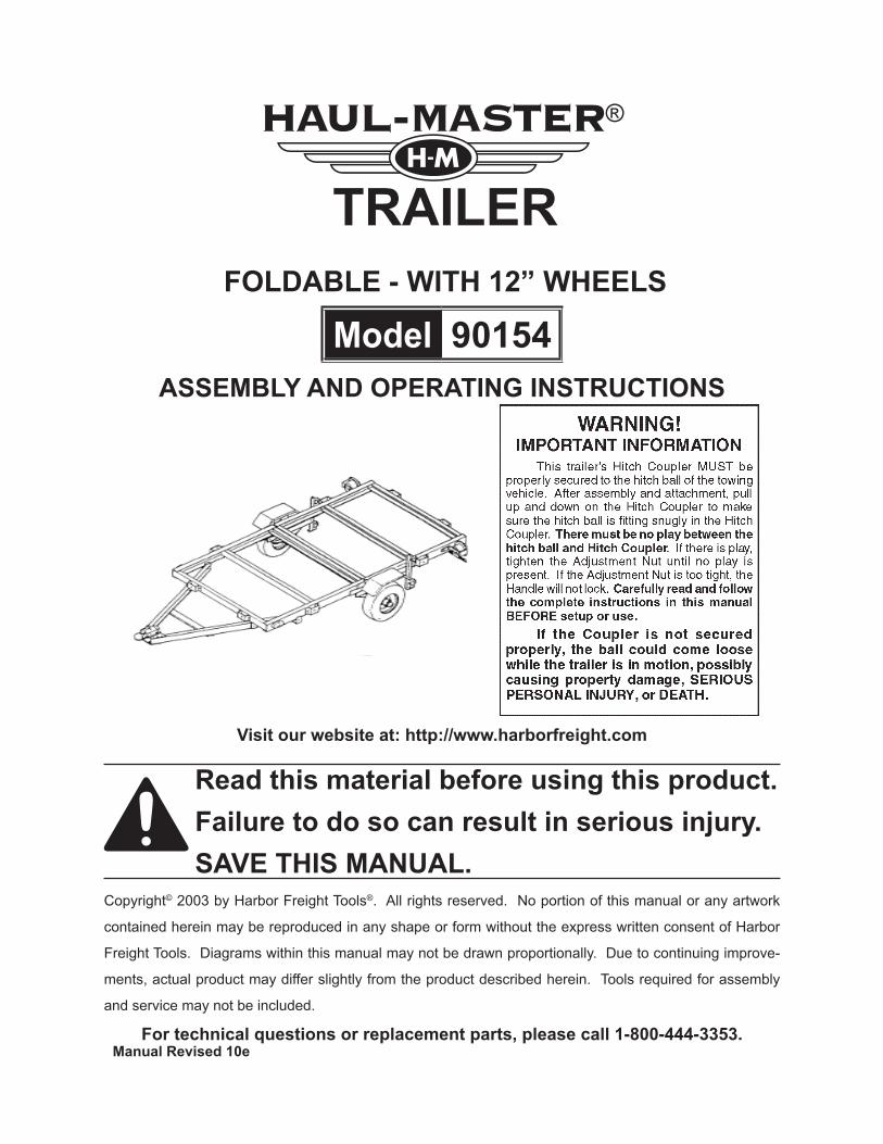
tRaileRfoldable - with 12” wheels
Model 90154asseMbly and opeRating instRuctions
Visit our website at: http://www.harborfreight.com
Read this material before using this product. failure to do so can result in serious injury. saVe this Manual.
Copyright© 2003 by Harbor Freight Tools®. All rights reserved. No portion of this manual or any artwork
contained herein may be reproduced in any shape or form without the express written consent of Harbor
Freight Tools. Diagrams within this manual may not be drawn proportionally. Due to continuing improve-
ments, actual product may differ slightly from the product described herein. Tools required for assembly
and service may not be included.
for technical questions or replacement parts, please call 1-800-444-3353.

SKU 90154 For technical questions, please call 1-800-444-3353. PAGE 2
contentsspecifications .................................................................................... 3geneRal safety waRnings and pRecautions ........................ 3
Specific Product Warnings and Precautions .....................................................4
unpacKing ............................................................................................ 6asseMbly instRuctions .................................................................. 6tiRe infoRMation .............................................................................. 18
tire terminology glossary ..................................................................................18tire Markings ........................................................................................................19Tire Inflation and Load Limit ...............................................................................20
tiRe caRe ............................................................................................. 21checking tire pressure .......................................................................................21steps for Maintaining proper tire pressure ......................................................21tire size ................................................................................................................22tire tread ..............................................................................................................22tire Rotation .........................................................................................................22tire balance and alignment ................................................................................22tire Repair ............................................................................................................22
Vehicle load liMit ........................................................................... 23steps for determining correct load limit .........................................................23
inspection, Maintenance, and cleaning ................................ 23wiring diagram .....................................................................................................24
paRts list ............................................................................................ 25assembly diagram ...............................................................................................26
RepoRting safety defects .......................................................... 26beaRing pacKing instRuctions ................................................... 27

SKU 90154 For technical questions, please call 1-800-444-3353. PAGE 3
specifications
Maximum Capacity Payload 1,195 lb.
Bed Dimensions 4 Ft. x 8 Ft.
Hitch Ball Size 1-7/8”
Wheel Rim Diameter/Width 12” x 4”
Quantity Wheel Lug Nuts 4 Per Wheel
Tire Size 4.80 - 12
Required Tire Air Pressure 60 PSI, Cold
Overall Dimensions 110” L x 61-1/2” W x 19-1/4” H
Ship Weight / Net Weight 262 Lbs. / 252 Lbs.
saVe this ManualYou will need this manual for the safety warnings and precautions, assembly, oper-
ating, inspection, maintenance and cleaning procedures, parts list and assembly diagram. Keep your invoice with this manual. Write the invoice number on the inside of the front cover. Keep this manual and invoice in a safe and dry place for future reference.
geneRal safety waRnings and pRecautionsKeep work area clean and dry. Cluttered, damp, or wet work areas invite injuries.1.
Keep children away from work area. Do not allow children to handle this product.2.
Store idle equipment. When not in use, tools and equipment should be stored in 3. a dry location to inhibit rust. Always lock up tools and equipment, and keep out of reach of children.
Do not use this product if under the influence of alcohol or drugs. Read warning 4. labels on prescriptions to determine if your judgement or reflexes are impaired while taking drugs. If there is any doubt, do not attempt to use this product.
Use eye protection. Wear ANSI-approved safety impact eye goggles when 5. assembling this product.
Dress safely. Do not wear loose clothing or jewelry, as they can become caught in 6. moving parts. Wear a protective hair covering to prevent long hair from becoming caught in moving parts. If wearing a long-sleeve shirt, roll sleeves up above elbows. Wearing safety work shoes is recommended.
Do not overreach. Keep proper footing and balance at all times to prevent tripping, 7. falling, back injury, etc.
ReV 06k; 09b

SKU 90154 For technical questions, please call 1-800-444-3353. PAGE 4
Industrial applications must follow OSHA requirements.8.
Stay alert. Watch what you are doing at all times. Use common sense. Do not use 9. this product when you are tired or distracted from the job at hand.
Check for damaged parts. Before using this product, carefully check that it will 10. operate properly and perform its intended function. Check for damaged parts and any other conditions that may affect the operation of this product. Replace dam-aged or worn parts immediately.
Replacement parts and accessories: when servicing, use only identical replacement 11. parts. Only use accessories intended for use with this product. Approved acces-sories are available from harbor freight tools.
Maintain this product with care. Keep this product clean and dry for better and 12. safer performance.
Maintenance: for your safety, service and maintenance should be performed regu-13. larly by a qualified technician.
Use the right tool for the job. Do not attempt to force small equipment to do the 14. work of larger industrial equipment. There are certain applications for which this equipment was designed. It will do the job better and more safely at the capacity for which it was intended. Do not modify this equipment, and do not use this equip-ment for a purpose for which it was not intended.
waRning:15. The warnings, precautions, and instructions discussed in this manual cannot cover all possible conditions and situations that may occur. The operator must understand that common sense and caution are factors, which cannot be built into this product, but must be supplied by the operator.
Specific Product Warnings and Precautionsto aVoid peRsonal inJuRy and/oR pRopeRty daMage, do not eX-1. ceed the tRaileR’s MaXiMuM capacity payload of 1,195 pounds.
b2. efoRe each use, always eXaMine the tRaileR foR pRopeR tiRe (19) condition and aiR pRessuRe, daMaged tail lights (28l, 28R), daMaged side Running lights (24), loose bolts and nuts, stRuc-tuRal cRacKs, bends, and any otheR condition that May affect its safe opeRation. Do not use the Trailer even if minor damage appears.
neVeR allow adults, childRen, oR pets to3. Ride on the tRaileR.
befoRe each use, always attach the safety chain (8) of the 4. tRaileR to the towing Vehicle. Make sure the Safety Chain is attached to the towing vehicle with the equal length at each side. Do not allow the Safety Chain to drag on the ground.
09b
SKU 90154 For technical questions, please call 1-800-444-3353. PAGE 5
always checK to MaKe suRe the payload being tRanspoRted is 5. pRopeRly and safely secuRed in the tRaileR. Load the Trailer evenly from side to side with 60% of the load forward of the Axle (16).
MaKe suRe the towing Vehicle is capable of towing the tRaileR 6. and its payload. Make sure the hitch on the towing vehicle is capable of towing the Trailer and its payload. The towing capacity of the hitch is typically stamped on the hitch drawbar.
MaKe suRe the hitch coupleR (7) and the Vehicle’s ball hitch (not 7. included) aRe of eQual Mating siZe (1-7/8”) and aRe Rated eQual to oR gReateR than the weight of the tRaileR and its payload.
do not eXceed 45 Miles peR houR when towing the tRaileR.8. Excess speed is a major cause of vehicle-trailer accidents.
the tail light bulbs supplied with this tRaileR aRe foR a 12 Volt 9. dc (negatiVe eaRth) electRical systeM only. Do not attempt to power the Light Bulbs with any other type or voltage electrical current.
wheneVeR possible, paRK the tRaileR on a flat, leVel, paVed, 10. suRface and chocK both tiRes to Keep the tRaileR fRoM acci-dently MoVing.
BEFORE ATTEMPTING TO FOLD UP THE TRAILER, make sure it is on a flat, 11. level, solid surface and chock both tires (19).
befoRe standing up the tRaileR, pRopeRly secuRe the ReaR and 12. fRont section togetheR (see instRuctions on page 13).
neVeR atteMpt to fold up the tRaileR without the help of one 13. oR two able assistants.
tRaileR licensing notice:14. Some states may consider this Trailer a vehicle requiring registration, licensing, and titling. Check with your State Department of Motor Vehicles for information and guidance on registering, licensing, and titling the Trailer.
Maintain labels and naMeplates on the tRaileR.15. These carry im-portant information. If unreadable or missing, contact Harbor Freight Tools for a replacement.

SKU 90154 For technical questions, please call 1-800-444-3353. PAGE 6
unpacKingWhen unpacking, check to make sure all the parts shown on the parts list (page
19) are included. If any parts are missing or broken, please call Harbor Freight Tools at the number shown on the cover of this manual as soon as possible.
asseMbly instRuctionsnote: For additional references to the parts listed on the following pages, refer to the as-
sembly diagram (page 20). be sure to read the bearing packing instructions on the last page of this manual.
facing fRont of tRaileR
fRont
figuRe a
1. On a flat, level, surface, lay out one Front Left Side Rail (1FL), one Front Right Side Rail (1FR), one Cross Member (2A), and two Cross Members (2B). Lay out two Hinge Plates (10) and two Stake Clamps (25). Assemble the parts, using the 3/8” x 3/4” Bolts (A), 3/8” Nylon Nuts (G) and also the 3/8” x 1” Bolts (B) and 3/8” Nylon Nuts (G). (see figure a.)
Attach the Left Connecting Rail (3L) and the Right Connecting Rail (3R) to the Front 2. Left Side Rail (1FL) and Front Right Side Rail (1FR), using the 9/16” Bolts (E), 9/16” Hex Nuts (I), and 1/8” Cotter Pins (P).
fRont bed
SKU 90154 For technical questions, please call 1-800-444-3353. PAGE 7
figuRe b
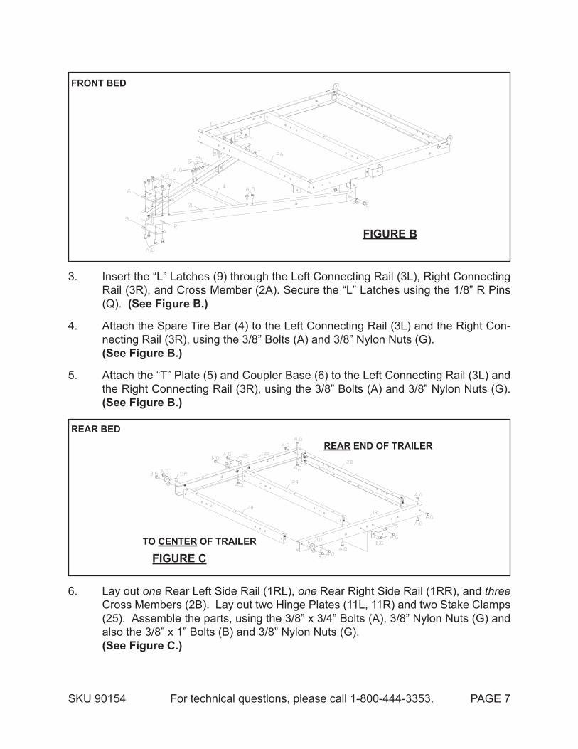
3. Insert the “L” Latches (9) through the Left Connecting Rail (3L), Right Connecting Rail (3R), and Cross Member (2A). Secure the “L” Latches using the 1/8” R Pins (Q). (see figure b.)
Attach the Spare Tire Bar (4) to the Left Connecting Rail (3L) and the Right Con-4. necting Rail (3R), using the 3/8” Bolts (A) and 3/8” Nylon Nuts (G). (see figure b.)
Attach the “T” Plate (5) and Coupler Base (6) to the Left Connecting Rail (3L) and 5. the Right Connecting Rail (3R), using the 3/8” Bolts (A) and 3/8” Nylon Nuts (G). (see figure b.)
ReaR end of tRaileR
to centeR of tRaileR
figuRe c
6. Lay out one Rear Left Side Rail (1RL), one Rear Right Side Rail (1RR), and three Cross Members (2B). Lay out two Hinge Plates (11L, 11R) and two Stake Clamps (25). Assemble the parts, using the 3/8” x 3/4” Bolts (A), 3/8” Nylon Nuts (G) and also the 3/8” x 1” Bolts (B) and 3/8” Nylon Nuts (G). (see figure c.)
fRont bed
ReaR bed

SKU 90154 For technical questions, please call 1-800-444-3353. PAGE 8
ReaR poRtion
folded tRaileR
fRont poRtion
figuRe d
7. Assemble the front portion and the rear portion of the Trailer, using the 3/8” x 3/4” Bolts (A), 3/8” Nylon Nuts (G). Then, fold the Trailer with assistance. (see figure d.)
figuRe e
8. With the Trailer in its folded position, attach the Spring Hanger (12L) to the Front Left Side Rail (1FL), using 3/8” x 1” Bolts (B) and 3/8” Nylon Nuts (G). Attach the Spring Hanger (12R) to the Front Right Side Rail (1FR), using 3/8” x 1” Bolts (B) and 3/8” Nylon Nuts (G). (see figure e.)

SKU 90154 For technical questions, please call 1-800-444-3353. PAGE 9ReV 06b
Attach the Caster Base (30L) to the Spring Hanger (12L), using 3/8” x 1” Bolts (B) 9. and 3/8” Nylon Nuts (G). Attach the Caster Base (30R) to the Spring Hanger (12R), using 3/8” x 1” Bolts (A) and 3/8” Nylon Nuts (G). (see figure e.)
Attach the Casters (13) to the two Caster Bases (30L, 30R), using M8 Nylon Nuts 10. (U). (see figure e.)
figuRe f
11. Attach the two Fender Support (23) to the two Caster Bases (30L, 30R), using the 3/8” Bolts (A) and 3/8” Nylon Nuts (G). Then attach the two Fenders (22) to the two Fender Support, using the 3/8” Bolts (A) and 3/8” Nylon Nuts (G). (see figure f.)
Attach the two Springs (15) to the two Caster Bases (30L, 30R), using 9/16” x 3-1/4” 12. Bolts (E) and 9/16” Hex Nuts (I). Leave these Bolts loose for now to allow proper assembly in the next step. Insert a Cotter Pin (P) through the holes in the end of the Bolts and spread the Cotter Pins. (see figure f.)
Align the guide pin at end of axles through the Springs (15). Position the two Spring 13. Plates (14) under the two Springs. Axle guide pins must be located in the center hole of the Spring Plates (14). On each end of the Axle, insert two U-Bolts (17) downward over the Axle and through the mounting holes in each of the two Spring Plates. The Spring Plates may need to be adjusted slightly to allow the holes to line up. Then secure the Axle and Spring assemblies, using 3/8” Spring Washers

SKU 90154 For technical questions, please call 1-800-444-3353. PAGE 10ReV 04g
(L) and 3/8” Nylon Nuts (G). After doing this, tighten the Bolts (E) and Nuts (I) left loose in the last step. (see figure f.)
figuRe g
note: peRiodically, gRease seal (32)on bacKside of hub (18).
14. Attach the Grease Fitting (31) to the Hub (18). Carefully slide a Hub over the spindle at each end of the Axle (16). Follow the directions on Bearing Packing below. Insert the Outer Bearings (20) onto the spindles of both ends of the Axle. Insert the 3/4” Flat Washer (N) onto each spindle of the Axle. Then secure the Hub and Bearing assemblies, using the Castle Nuts (K). (see figure g.)
beaRing pacKing instRuctions
waRningRead and adhere to the following instructions; failure to read and obey all
of the following instructions coMpletely will void the warranty and can result in damage to the trailer, property damage, or seRious peRsonal inJuRy.
whenever a hub is disassembled (if a hub on a new unit requires assembly or a hub is disassembled for maintenance), the following procedure Must be followed.a. Using a suitable solvent, thoroughly clean the bearings and the rest of the parts in
the Hub assembly of all grease, dirt, metal shavings, or any other foreign object. the parts must be cleaned even if they are new or appear clean.
b. Allow all pieces to dry completely.c. Make sure that your hands are thoroughly clean and the bearing packer (not included)
is also thoroughly clean.d. Place fresh, clean bearing grease in the packer.e. With the grease-filled bearing packer in one hand and the bearing in the other,

SKU 90154 For technical questions, please call 1-800-444-3353. PAGE 11
See point 4 of Inspection, Maintenance and Cleaning (page 24). Make sure the 15. Hub rotates freely. If not, back off the Castle Nut very slightly until the Hub rotates freely. (see figure g.)
Press each Dust Cap onto each Hub (18). 16. (see figure g.)
Place a Tire/Wheel Assembly (19) onto each Hub (18). Secure each Tire/Wheel 17. assembly firmly to the Hubs, using the Lug Nuts (J) note: Make sure the Lug Nuts are torqued to at least 90 ft-lb.
figuRe h
18. With assistance, extend the Trailer Bed to full length by unfolding Rear Bed com-pletely. Secure Rear Bed to Rear Left and Right Side Rails (1RL) and (1RR) using M10x30 Carriage Bolts (D), Washer (a), Spring Washer (b) and Hex Nut (c). (see figure h.)
Attach the Coupler (7) to the Coupler Base (6), using 1 M10x90 Bolt (W) at the 19. rear of the coupler. Lock the Coupler Trigger with the Safety Pin (29). Then, insert the “R” Pin (S) through the hole in the Safety Pin (29) to secure the Safety Pin in place. (see figure h.)
Insert the second M10x90 Bolt (W) through the Coupler (7) and Coupler Base (6) 20. as well as through the center link of the Safety Chain. Then, use a 3/8” Nylon Nut (G) to secure the Safety Chain to the Hitch Coupler. (see figure h.)
Attach two Stake Clamps (25) to the Front Cross Member (2A), using M10x20 Bolts 21. (A) and M10 Nylon Nuts (G). Then, repeat this Step for the remaining two Stake Clamps and the Rear Cross Member (2B). (see figure h.)
press the bearing into the grease, forcing the grease inside the slots in the bearing, continue doing this until every slot in the bearing is completely full of grease.
f. Finish assembling the hub/wheel assembly as explained in this manual, being care-ful not to get any dirt or debris on any part of the assembly.
6

SKU 90154 For technical questions, please call 1-800-444-3353. PAGE 12
Remove the Lens from a Side Running Light (24). Insert the Wire Lead of the Side 22. Running Light through the center hole of the Front Left Side Rail (1FL). Attach the Side Running Light to the Front Left Side Rail, using the Self Tapping Screws (R). Then, reattach the Lens to the Side Running Light. Repeat this Step for the remaining Side Running Light and the Front Right Side Rail (1FR). (see figure h.)
Attach a Tail Light Bracket (26) to the Rear Left Side Rail (1RL), using M10x20 Bolts 23. (A) and M10 Nylon Nuts (G). Attach the License Plate Bracket (27) and Left Tail Light (28L) to the Tail Light Bracket, using 3/8” Nylon Nuts (G). Repeat this Step for the remaining Tail Light Bracket and Rear Right Side Rail (1RR). (see figure h.)
Secure the rear Bed of the Trailer’s frame to the Caster Bases (30L, 30R), using 24. M10x30 Carriage Bolts (D) and M10 Nylon Nuts (G). (see figure h.)
wiRe leadfRoM
side Running light(24)
white gRound wiRe
wiRe leadfRoM
side Running light(24)
bRown yellow gReen bRown
yellow
Red
bRown
blacK
gReen
Red
bRown
blacK
leaVe 16” eXcess wiRe heRe. leaVe 16” eXcess wiRe heRe.
left tail light (28l) Right tail light (28R)figuRe i
wiRe haRness connectoR plug
25. To install the Wiring Harness on the Trailer, use a Self Tapping Screw (R) to attach the White Ground Wire located at the Plug end of the Wiring Harness to the small

SKU 90154 For technical questions, please call 1-800-444-3353. PAGE 13
mounting hole in the Right Connecting Rail (3R). (see figure i.)
Leave about 18” of wire beyond the Hitch Coupler (7), and run the Wiring Harness 26. along the inside of the Right Connection Rail (3R) to the Front Right Side Rail (1FR). Then, split the Yellow/Brown Wires from the Green/Brown Wires. (see figure i.)
Run the Yellow/Brown Wires along the inside of the Front Cross Member (2A) to 27. the Side Running Light (24) located on the Front Left Side Rail (1FL). Then, run the Green/Brown Wires along the inside of the Front Right Side Rail (1FR) to the other Side Running Light. (see figure i.)
Connect the Wire Lead from the two Side Running Lights (24) to the Brown Wire on 28. each side of the Trailer. Then, insert Wire Clips along the entire length of the Side Rails of the Trailer to hold down the Wiring Harness. (see figure i.)
Run the Yellow/Brown Wires to the Left Tail Light (28L). Strip the ends of the Wires 29. about 3/4”. Connect the Yellow Wire to the Red Wire of the Left Tail Light. Then, connect the Brown Wire to the two Black Wires of the Left Tail Light. (see figure i.)
Run the Green/Brown Wires to the Right Tail Light (28R). Strip the ends of the 30. Wires about 3/4”. Connect the Green Wire to the Red Wire of the Right Tail Light. Then, connect the Brown Wire to the two Black Wires of the Right Tail Light. (see figure i.)
note:31. It is recommended that only a qualified technician perform the electrical service that may be needed to enable your particular make/model vehicle to power the Trailer’s 12 volt DC lighting system.

SKU 90154 For technical questions, please call 1-800-444-3353. PAGE 14
figuRe J
32. To fold the Trailer, unscrew and remove the two 3/8” x 1” Carriage Bolts (D) from the Rear Left Side Rail (1RL) and Rear Right Side Rail (1RR). (see figure J.)
With the assistance of one or two helpers, fold the rear section of the Trailer over 33. the front section of the Trailer. Secure the rear section and front section together with 4 elastic cords (not included) or rope. The bungee cords should be distributed around all sides of the rear and front section to hold them together while the Trailer is folded up. (see figure J.)
With the assistance of one or two helpers, remove wheel chocks and carefully tilt 34. the Trailer onto its Casters (13). When tilting the Trailer, always apply pressure on the middle section (where the rear and front section are secured together). Trying to maneuver the Trailer vertically by handling the front connecting Rails (3L, 3R) can make the Trailer unstable. while tilting and transporting the trailer, frequently inspect the condition of the casters; if the casters become damaged or de-formed, immediately stop the trailer movement. When transporting the folded Trailer, always seek the help of an assistant to prevent the Trailer from tipping over. To be safe, store the Trailer against a wall, securing it to the wall by elastic cords or rope. Then, remove the two “L” Latches (9) and fold the Trailer Tongue down. (see figure J.)
note:35. To avoid damage to Casters (13), avoid rolling the Trailer on its Casters over long distances. The Casters should only be rolled over a flat, level and hard surface.
The Trailer must be on a flat, level surface before attempting to fold it up and always chock both Tires (19).
waRning:

SKU 90154 For technical questions, please call 1-800-444-3353. PAGE 15
48
48
48 48
9.299.29
13.96
14.35
8.90.75
4.37
4.37
13.96
13.96
4.37
4.37
18.9
18.9
18.9
18.9
9.29
3/8” cRoss head bolt
3/8” flat washeR
3/8” spRing washeR3/8” heX nut
figuRe K
36. To attach a bed (not included) to the frame of the Trailer, it is recommended to use the following parts:
Qty. 2a. : 3/4” x 48” x 48” Plywood (not included).Qty. 24-30b. : 3/8” Cross Head Bolts (not included).Qty. 24-30c. : 3/8” Flat Washers (not included).Qty. 24-30d. : 3/8” Spring Washers (not included).Qty: 24-30e. : 3/8” Hex Nuts (not included).
(see figure K.)
As shown in the diagram, drill all mounting holes with a 3/8” high speed drill bit. 37. (see figure K.)
Use the 3/8” Cross Head Bolts, 3/8” Flat Washers, 3/8” Spring Washers, and 3/8” 38. Hex Nuts to secure the Plywood bed to the Trailer frame. (see figure K.)
SKU 90154 For technical questions, please call 1-800-444-3353. PAGE 16
figuRe l
3/8” diaMeteR
2
1.6
0.75
0.75
3/8” diaMeteR
1.25 1.252 2
0.75
2
94.51.25
R2
18.5825250.835218.5825
3.5
3/8” diaMeteR
28224282
3.5 2
271.25626.526.52
3.5
side Rail
staKe
fRont endbacK end Rail
connecting plate
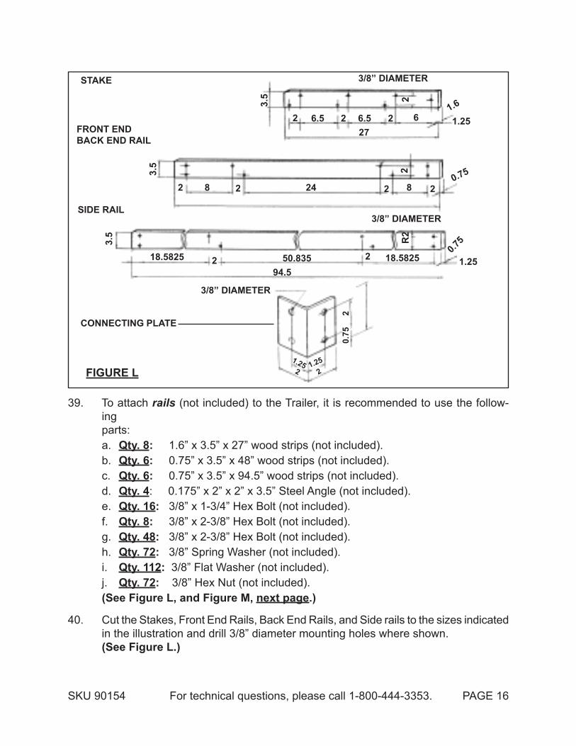
39. To attach rails (not included) to the Trailer, it is recommended to use the follow-ing parts:
Qty. 8a. : 1.6” x 3.5” x 27” wood strips (not included).Qty. 6b. : 0.75” x 3.5” x 48” wood strips (not included).Qty. 6c. : 0.75” x 3.5” x 94.5” wood strips (not included).Qty. 4d. : 0.175” x 2” x 2” x 3.5” Steel Angle (not included).Qty. 16e. : 3/8” x 1-3/4” Hex Bolt (not included).Qty. 8f. : 3/8” x 2-3/8” Hex Bolt (not included).Qty. 48g. : 3/8” x 2-3/8” Hex Bolt (not included).Qty. 72h. : 3/8” Spring Washer (not included).Qty. 112i. : 3/8” Flat Washer (not included).Qty. 72j. : 3/8” Hex Nut (not included).
(see figure l, and figure M, next page.)
Cut the Stakes, Front End Rails, Back End Rails, and Side rails to the sizes indicated 40. in the illustration and drill 3/8” diameter mounting holes where shown. (see figure l.)

SKU 90154 For technical questions, please call 1-800-444-3353. PAGE 17
figuRe M
3/8” nut3/8” spRing
washeR
3/8” flatwasheR
3/8” X 1-3/4”cRoss head bolt
3/8” nut
3/8” spRingwasheR
3/8” flatwasheR
3/8” spRingwasheR
3/8” flatwasheR
3/8” X 3-3/8” cRoss head bolt
staKe claMp(25)
3/8” X 2-3/8”heX bolt
connectingplate
fRont endRail
bacK endRail
side Rail
side Rail
41. To determine where to drill 3/8” holes in the Stakes, place the eight Stakes in the eight Stake Clamps (25) of the Trailer and mark with a pencil. (see figure l, and figure M.)
Attach the Side Rails and Front End/Back End Rails to the Stakes, using 3/8” x 42. 3-3/8” Cross Head Bolts, 3/8” Flat Washers, and 3/8” Nuts. (see figure M.)
Secure the stakes to the Stake Clamps (25) of the Trailer, using 3/8” x 2-3/8” Hex 43. Bolts, 3/8” Spring Washers, and 3/8” Nuts. (see figure M.)
Attach the Connecting Plates to the Side Rails and Front End/Back End Rails, using 44. 3/8” x 1-3/4” Cross Head Bolts and 3/8” Nuts. (see figure M.)
note:45. For quick folding purposes, you may not want to bolt down the Stakes permanently to the Stake Clamps (25) of the Trailer.
SKU 90154 For technical questions, please call 1-800-444-3353. PAGE 18
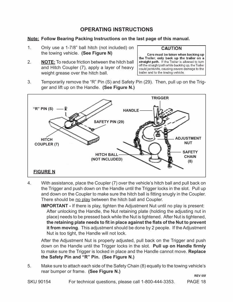
opeRating instRuctionsnote: follow bearing packing instructions on the last page of this manual.
Only use a 1-7/8” ball hitch (not included) on 1. the towing vehicle. (see figure n)
note:2. To reduce friction between the hitch ball and Hitch Coupler (7), apply a layer of heavy weight grease over the hitch ball.
Temporarily remove the “R” Pin (S) and Safety Pin (29). Then, pull up on the Trig-3. ger and lift up on the Handle. (see figure n.)
hitchcoupleR (7)
safety pin (29)
“R” pin (s)
hitch ball(not included)
handle
tRiggeR
adJustMentnut
safetychain
(8)
figuRe n
4. With assistance, place the Coupler (7) over the vehicle’s hitch ball and pull back on the Trigger and push down on the Handle until the Trigger locks in the slot. Pull up and down on the Coupler to make sure the hitch ball is fitting snugly in the Coupler. There should be no play between the hitch ball and Coupler.
iMpoRtant - If there is play, tighten the Adjustment Nut until no play is present:After unlocking the Handle, the Nut retaining plate (holding the adjusting nut in place) needs to be pressed back while the Nut is tightened. After Nut is tightened, the retaining plate needs to fit in place against the flats of the Nut to prevent it from moving. This adjustment should be done by 2 people. If the Adjustment Nut is too tight, the Handle will not lock.
After the Adjustment Nut is properly adjusted, pull back on the Trigger and push down on the Handle until the Trigger locks in the slot. Pull up on Handle firmly to make sure the Trigger is locked in place and the Handle cannot move. Replace the safety pin and “R” pin. (see figure n.)
Make sure to attach each side of the Safety Chain (8) equally to the towing vehicle’s 5. rear bumper or frame. (see figure n.)
ReV 05f

SKU 90154 For technical questions, please call 1-800-444-3353. PAGE 19
Connect the Tail Light Wiring Assembly to the towing vehicle’s 12 Volt DC system. 6. note: Make sure to consult the operator’s manual of the towing vehicle for proper connection instructions.
When towing the Trailer over long distances stop and check the tightness of all 7. connections, Side Running Lights (24), and Tail Lights (28L, 28R) at least every 100 miles.
Carry emergency flares, and fire extinguisher, if required for operation in your state. 8. It is recommended to carry extra bulbs and fuses if towing the Trailer at night over long distances.
tiRe infoRMation
tire terminology glossaryaccessory weight means• - the combined weight of automatic transmission, power steering, power brakes, power windows, power seats, radio, and heater, to the extent that these items are available as factory-installed equipment.carcass means• - the tire structure except for the tread which provides the major portion of the tire’s capability to deflect in response to the vertical loads and tractive forces that the tire transmits from the roadway to the non-pneumatic rim, the wheel center member, or the vehicle and which attaches to the vehicle or attaches, either integrally or separably, to the wheel center member or non-pneumatic rim.carcass separation means• - the pulling away of the carcass from the non-pneumatic rim or wheel center member.chunking means• - the breaking away of pieces of the carcass or tread.cracking means• - any parting within the carcass, tread, or any components that connect the tire to the wheel center member.curb weight means• - the weight of a motor vehicle with standard equipment including the maximum capacity of fuel, oil, and coolant, and, if so equipped, air conditioning and additional weight optional engine.load rating means• - the maximum load a tire is rated to carry.Maximum loaded vehicle weight means• - the sum of:
Curb weight;a. Accessory weight;b. Vehicle capacity weight; andc. Production options weight.d.
Maximum tire width means• - the greater of either the linear distance between the exterior edges of the carcass or the linear distance between the exterior edges of the tread, both being measured parallel to the rolling axis of the tire.normal occupant weight means• - 68 kilograms times the number of occupants.occupant distribution means• - distribution of occupants in a vehicle.production options weight means• - the combined weight of those installed regular production options weighing over 2.3 kilograms in excess of those standard items which they replace, not previously con-sidered in curb weight or accessory weight, including heavy duty brakes, ride levelers, roof rack, heavy duty battery, and special trim.tread means• - that portion of the tire that comes in contact with the road.
SKU 90154 For technical questions, please call 1-800-444-3353. PAGE 20
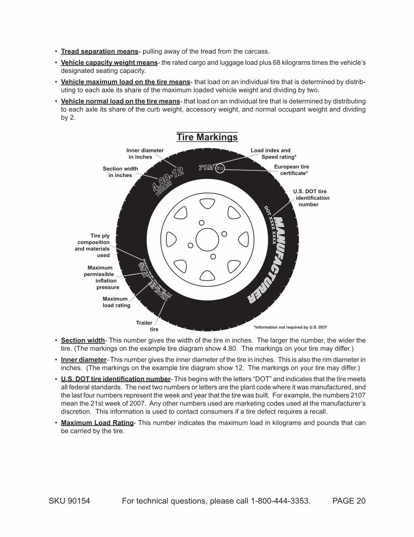
tread separation means• - pulling away of the tread from the carcass.Vehicle capacity weight means• - the rated cargo and luggage load plus 68 kilograms times the vehicle’s designated seating capacity.Vehicle maximum load on the tire means• - that load on an individual tire that is determined by distrib-uting to each axle its share of the maximum loaded vehicle weight and dividing by two.Vehicle normal load on the tire means• - that load on an individual tire that is determined by distributing to each axle its share of the curb weight, accessory weight, and normal occupant weight and dividing by 2.
tire Markingsload index and
speed rating*
european tire certificate*
u.s. dot tire identification number
*information not required by u.s. dot
inner diameter in inches
section width in inches
trailer tire
Maximum load rating
tire ply composition
and materials used
Maximum permissible
inflation pressure
section width• - This number gives the width of the tire in inches. The larger the number, the wider the tire. (The markings on the example tire diagram show 4.80. The markings on your tire may differ.)inner diameter• - This number gives the inner diameter of the tire in inches. This is also the rim diameter in inches. (The markings on the example tire diagram show 12. The markings on your tire may differ.)U.S. DOT tire identification number• - This begins with the letters “DOT” and indicates that the tire meets all federal standards. The next two numbers or letters are the plant code where it was manufactured, and the last four numbers represent the week and year that the tire was built. For example, the numbers 2107 mean the 21st week of 2007. Any other numbers used are marketing codes used at the manufacturer’s discretion. This information is used to contact consumers if a tire defect requires a recall.Maximum load Rating• - This number indicates the maximum load in kilograms and pounds that can be carried by the tire.

SKU 90154 For technical questions, please call 1-800-444-3353. PAGE 21
code pounds71 76172 78373 80574 82775 85376 88277 90878 937
code pounds79 96380 99281 1,01982 1,04783 1,07484 1,10285 1,13586 1,168
code pounds87 1,20188 1,23589 1,27990 1,32391 1,35692 1,38993 1,43394 1,477
code pounds95 1,52196 1,56597 1,60998 1,65399 1,709100 1,764101 1,819102 1,874
code pounds103 1,929104 1,984105 2,039106 2,094107 2,149108 2,205109 2,271110 2,337
load index Rating codes
• load index- This is a measurement of how much weight each tire can support. See chart above. (The markings on the example tire diagram show 71. The markings on your tire may differ.) Note: You may not find this information on all tires because it is not required by law.speed Rating• - The speed rating denotes the speed at which a tire is designed to be driven for extended periods of time. This does not indicate that the vehicle or rims can safely reach or maintain that speed. These ratings are listed to the right. (The markings on the example tire diagram show M. The markings on your tire may differ.) Note: You may not find this information on all tires because it is not required by law.tire ply composition and Materials used• - The number of plies indicates the number of layers of rubber-coated fabric in the tire. In general, the greater the number of plies, the more weight a tire can support. Tire manufacturers also must indicate the materials in the tire, which include steel, nylon, polyester, and others.Maximum Permissible Inflation Pressure• - This number is the greatest amount of air pressure that should ever be put in the tire under normal driving conditions.
Tire Inflation and Load Limit
tire and loading information placard
tiRe and loading infoRMation
The weight of cargo should never exceed 541 kg or 1195 lb.
tiRe siZe cold tiRe pRessuRe see owneR’s Manual foR additional
infoRMation.
fRont 4.80/4.00-12 410 kpa, 60 psi
ReaR none none
spaRe none none
09g
Mo
del
901
54
tire and loading information placard location
The Tire and Loading Information Placard displays the cold tire inflation pressure and the load limit for this vehicle. See the Tire Care section starting on the following page for an explanation of tire pressure and see the Vehicle Load Limit following that for an explanation of load limit.
code MphF 50G 56J 62K 68L 75M 81
code MphN 87P 94Q 100R 106S 112T 118
code MphU 124H 130V 149Z 149W 168Y 186
tire speed Rating codes
ReV 09b, 09g, 10e

SKU 90154 For technical questions, please call 1-800-444-3353. PAGE 22
tiRe caRe
checking tire pressurenote: Underinflated tires can decrease handling, stopping performance, traction, tire life,
and load-carrying capability, in addition to causing other negative and hazardous effects, including tire failure. Overinflated tires are at greater risk of an impact break, where the tread and casing break when striking a hard edge, often opening a huge gash across the tread. Incorrect inflation pressure also increases tires wear rate. Therefore, it is important to keep tires inflated properly.
Check all tires’ pressure at least monthly, due to the following factors:Most tires naturally lose air gradually.• Tires can suddenly lose air if the tire strikes a pothole, curb, or other object.• It is usually not possible to determine underinflation of radial tires by visual in-• spection.
This vehicle has 60 PSI recommended cold tire inflation pressure. The term “cold” in this manual does not refer to the temperature outside, but it refers to the fact that a tire that has not been driven for a period is cooler (and therefore has lower pressure) than a tire that has been driven on. Tires heat up while being driven on. To check (or fill to) a tire’s cold inflation, the tire must have not been driven for more than a mile or two for at least three hours. If you check a tires pressure when it is not “cold”, the pressure will ap-pear higher than the actual cold tire inflation.
steps for Maintaining proper tire pressureLocate the recommended tire pressure on the vehicle’s tire information placard, 1. certification label, or in the owner’s manual. This trailer has 60 PSI recommended cold tire inflation pressure.
Measure and record the tire pressure of all tires.2.
If the tire pressure is too high in any of the tires and the tires have not been driven 3. for at least three hours, slowly release air by gently pressing on the tire valve stem with the edge of your tire gauge until you get to the correct pressure. If the vehicle have been driven within the past three hours and the tire pressure is too high on any tires, then recheck the pressure once the tires have been allowed to sit motionless for at least three hours.
If the tire pressure is too low, note the difference between the measured tire pres-4. sure and the correct tire pressure. These “missing” pounds of pressure are what you will need to add.
At a service station, add the missing pounds of air pressure to each tire that is 5. underinflated.

SKU 90154 For technical questions, please call 1-800-444-3353. PAGE 23
Check all the tires to make sure they have the same air pressure.6.
If the tires’ pressure was not measured “cold”, then the pressure should be rechecked 7. with the tires cold as soon as possible.
tire sizeTo maintain safety, only purchase new tires of the same size as the original tires.
Look at the Tire and Loading Information Placard, the Specifications Chart in this manual, or the sidewall of the tire being replaced. If you have any doubt about selecting the cor-rect size, consult a tire dealer.
tire treadThe tire tread provides traction that prevents your vehicle from slipping, especially
if the road is wet or icy. Tires are unsafe and should be replaced when the tread is worn down to 1/16”. Measure tread depth using a tread depth indicator (not included).
tire RotationEvery 5,000 miles the left and right tires should be switched. This will cause the
tires to wear more evenly and last longer.
tire balance and alignmentThe tires need to be balanced to prevent vibration when driving. This involves
attaching small weights to the rim to offset small differences in rim and tire weight. The tires also need to be aligned properly. Alignment is the orientation of the tires to the road surface and their being parallel. This helps the tires to wear evenly, and provide better traction. Both tire balance and alignment require specialized equipment that is not pro-vided with this vehicle.
tire RepairTo properly repair a punctured tire, the hole needs to be properly plugged and
patched from the inside of the tire. Tread punctures can be repaired if they are not too large. Sidewall punctures should not be repaired, the tire needs to be replaced if the sidewall is damaged. Tires should be removed from the rim to be inspected before being plugged and patched. A qualified mechanic should remove the tire from the rim, perform the repair, and remount the tire.

SKU 90154 For technical questions, please call 1-800-444-3353. PAGE 24
Vehicle load liMit
steps for determining correct load limitLocate the statement “The weight of cargo should never exceed XXX kilograms or 1. XXX pounds” on your vehicle’s placard.
That figure equals the available amount of cargo and luggage load capacity.2.
Determine the combined weight of luggage and cargo being loaded on the vehicle. 3. That weight may not safely exceed the available cargo and luggage load capac-ity.
If the trailer’s load exceeds the cargo and luggage load capacity, then the trailer 4. be unsafe resulting in hazardous effects, such as: Trailer’s tires will not be able to maintain traction properly, and stopping distance will be increased significantly.
inspection, Maintenance, and cleaningnote: follow bearing packing instructions on the last page of this manual.
befoRe each use,1. inspect the general condition of the Trailer. Check for loose Bolts and Nuts, misalignment or binding of moving parts, cracked, bent, or broken parts, excessively worn Safety Chain (8), damaged Tail Lights/Side Running Lights/Wiring Harness, loose Lug Nuts, loose Hitch connection, and any other condition that may affect its safe operation. If abnormal noise or vibration occurs, have the problem corrected before further use. do not use damaged equipment.
befoRe each use,2. check the Tires for wear and proper inflation (60 PSI).
befoRe eVeRy use and at 500 Mile inteRVals duRing eVeRy tRip3. , check and tighten the Tire Lug Nuts. Torque from 85 to 90 ft-lb.
eVeRy 2,000 to 3,000 Miles of use,4. lubricate the Hub Assemblies with a heavy weight bearing grease. After each Hub Assembly is reassembled, tighten the Castle Nut until the wheel starts spinning with slight resistance. Loosen the Castle Nut about 1/6 turn from this point. Insert a new Cotter Pin through the Castle Nut and the hole in the axle. Bend the Pin back, locking it and the Nut in place.
tRanspoRting the folded up tRaileR.5. The Trailer must be on a flat, level surface before attempting to fold it up, and always chock both tires. while tilting and transporting the trailer, frequently inspect the condition of the casters; if the casters become damaged or deformed, immediately stop the trailer movement. the folded up trailer should only be transported short distances.
to clean,6. use only water and a mild detergent.

SKU 90154 For technical questions, please call 1-800-444-3353. PAGE 25
wiring diagram
note: Some trailer tail lights will have two leads instead of three. They connect to the harness leads the same way; brown to brown, color to color.
ReV 06e
SKU 90154 For technical questions, please call 1-800-444-3353. PAGE 26
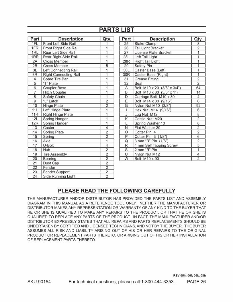
paRts listpart description Qty.1FL Front Left Side Rail 11FR Front Right Side Rail 11RL Rear Left Side Rail 11RR Rear Right Side Rail 12A Cross Member 12B Cross Member 53L Left Connecting Rail 13R Right Connecting Rail 14 Spare Tire Bar 15 “T” Plate 16 Coupler Base 17 Hitch Coupler 18 Safety Chain 19 “L” Latch 210 Hinge Plate 211L Left Hinge Plate 111R Right Hinge Plate 112L Spring Hanger 112R Spring Hanger 113 Caster 414 Spring Plate 215 Spring 216 Axle 117 U-Bolt 418 Hub 219 Tire Assembly 220 Bearing 221 Dust Cap 222 Fender 223 Fender Support 224 Side Running Light 2
part description Qty.25 Stake Clamp 826 Tail Light Bracket 227 License Plate Bracket 128L Left Tail Light 128R Right Tail Light 129 Safety Pin 130L Caster Base (Left) 130R Caster Base (Right) 131 Grease Fitting 232 Seal 2A Bolt M10 x 20 (3/8” x 3/4”) 64B Bolt M10 x 30 (3/8” x 1”) 14D Carriage Bolt M10 x 30 4E Bolt M14 x 80 (9/16”) 6G Nylon Nut M10 (3/8”) 92I Hex Nut M14 (9/16”) 6J Lug Nut M12 8K Castle Nut M20 2L Spring Washer 10 8N Flat Washer 20 2O Cotter Pin 4 2P Cotter Pin 3 (1/8”) 6Q 3 mm “R” Pin (1/8”) 2R 4 mm Self Tapping Screw 5S 2 mm “R” Pin 1U Nylon Nut M12 4W Bolt M10 x 90 2
please Read the following caRefullyTHE MANUFACTURER AND/OR DISTRIBUTOR HAS PROVIDED THE PARTS LIST AND ASSEMBLY DIAGRAM IN THIS MANUAL AS A REFERENCE TOOL ONLY. NEITHER THE MANUFACTURER OR DISTRIBUTOR MAKES ANY REPRESENTATION OR WARRANTY OF ANY KIND TO THE BUYER THAT HE OR SHE IS QUALIFIED TO MAKE ANY REPAIRS TO THE PRODUCT, OR THAT HE OR SHE IS QUALIFIED TO REPLACE ANY PARTS OF THE PRODUCT. IN FACT, THE MANUFACTURER AND/OR DISTRIBUTOR EXPRESSLY STATES THAT ALL REPAIRS AND PARTS REPLACEMENTS SHOULD BE UNDERTAKEN BY CERTIFIED AND LICENSED TECHNICIANS, AND NOT BY THE BUYER. THE BUYER ASSUMES ALL RISK AND LIABILITY ARISING OUT OF HIS OR HER REPAIRS TO THE ORIGINAL PRODUCT OR REPLACEMENT PARTS THERETO, OR ARISING OUT OF HIS OR HER INSTALLATION OF REPLACEMENT PARTS THERETO.
ReV 05h; 06f; 06k, 08h

SKU 90154 For technical questions, please call 1-800-444-3353. PAGE 27
assembly diagram
note: Some parts are listed and shown for illustration purposes only, and are not available individually as replacement parts.
RepoRting safety defectsIf you believe that your vehicle has a defect which could cause a crash or could
cause injury or death, you should immediately inform the National Traffic Safety Adminis-tration (NHTSA) in addition to notifying Changzhou Nanxiashu Tool Company. If NHTSA receives similar complaints, it may open an investigation. And if it finds that a safety defect exist in a group of vehicles, it may order a recall and remedy campaign. However, NHTSA cannot become involved in individual problems between you, your dealer, or Changzhou Nanxiashu Tool Company. To contact NHTSA, you may either call the Auto Safety Hotline toll-free at 1-800-424-9393 or 202-366-0123 or write to NHTSA, U. S. Department, 400 7th Street SW NSA-11, Washington, DC 20590. You can also obtain other information about motor vehicle safety from the Hotline. Note: Check with your local department of Motor Vehicles for registration procedures. Some DMV’s require the Certificate of Origin to be notarized, others do not.
beaRing pacKing instRuctions
waRningRead and adhere to the following instructions; failure to read and obey all
of the following instructions coMpletely will void the warranty and can result in damage to the trailer, property damage, or seRious peRsonal inJuRy.

SKU 90154 For technical questions, please call 1-800-444-3353. PAGE 28
liMited 90 day waRRantyHarbor Freight Tools Co. makes every effort to assure that its products meet high
quality and durability standards, and warrants to the original purchaser that this product is free from defects in materials and workmanship for the period of 90 days from the date of purchase. This warranty does not apply to damage due directly or indirectly, to misuse, abuse, negligence or accidents, repairs or alterations outside our facilities, criminal activity, improper installation, normal wear and tear, or to lack of maintenance. We shall in no event be liable for death, injuries to persons or property, or for incidental, contingent, special or consequential damages arising from the use of our product. Some states do not allow the exclusion or limitation of incidental or consequential damages, so the above limitation of exclusion may not apply to you. THIS WARRANTY IS EXPRESSLY IN LIEU OF ALL OTHER WARRANTIES, EXPRESS OR IMPLIED, INCLUDING THE WARRANTIES OF MERCHANTABILITY AND FITNESS.
To take advantage of this warranty, the product or part must be returned to us with transportation charges prepaid. Proof of purchase date and an explanation of the com-plaint must accompany the merchandise. If our inspection verifies the defect, we will either repair or replace the product at our election or we may elect to refund the purchase price if we cannot readily and quickly provide you with a replacement. We will return repaired products at our expense, but if we determine there is no defect, or that the defect resulted from causes not within the scope of our warranty, then you must bear the cost of returning the product.
This warranty gives you specific legal rights and you may also have other rights which vary from state to state.
3491 Mission Oaks Blvd. • PO Box 6009 • Camarillo, CA 93011 • (800) 444-3353
whenever a hub is disassembled (if a hub on a new unit requires assembly or a hub is disassembled for maintenance), the following procedure Must be followed.1. Using a suitable solvent, thoroughly clean the bearings and the rest of the parts in
the Hub assembly of all grease, dirt, metal shavings, or any other foreign object. the parts must be cleaned even if they are new or appear clean.
2. Allow all pieces to dry completely.3. Make sure that your hands are thoroughly clean and the bearing packer (not included)
is also thoroughly clean.4. Place fresh, clean bearing grease in the packer.5. With the grease-filled bearing packer in one hand and the bearing in the other,
press the bearing into the grease, forcing the grease inside the slots in the bearing, continue doing this until every slot in the bearing is completely full of grease.
6. Finish assembling the hub/wheel assembly as explained in this manual, being care-ful not to get any dirt or debris on any part of the assembly.


