Haptic Assisted Teleoperation Based on Virtual Fixture and ...
15
1367 Sensors and Materials, Vol. 29, No. 9 (2017) 1367–1381 MYU Tokyo S & M 1429 * Corresponding author: e-mail: [email protected] http://dx.doi.org/10.18494/SAM.2017.1605 ISSN 0914-4935 © MYU K.K. Haptic Assisted Teleoperation Based on Virtual Fixture and Dynamic Modelling Dejing Ni, Aiguo Song, * and Huijin Li School of Instrument Science and Engineering, Southeast University, Sipailou 2#, Nanjing, 210096, Jiangsu Province, China (Received March 20, 2017; accepted July 25, 2017) Keywords: virtual fixture, dynamic modelling, implicit surface, teleoperation It is a difficult task to teleoperate a robot in a partially known or unstructured environment without any assistance. In this paper, a haptic assisted teleoperation system is discussed that provides virtual fixtures for motion guidance and haptic feedbacks for dynamic interaction. First, a novel virtual fixture generation method based on a point-set implicit surface was proposed in a point cloud augmented virtual environment for human operational guidance. A robot-centered potential force field model was applied to generate guidance virtual fixtures. The resultant forces generated from both forbidden region and guidance virtual fixtures were fed back in real time to the human operator through a haptic device. Second, a real-time dynamic modelling method was proposed to reconstruct contacts in the teleoperation system. For the reconstruction of dynamic properties, an adaptive forgetting factor recursive least-squares method was applied for real-time parameter estimation. With haptic assistance from the motion guidance force and the dynamic force feedback, human operators could efficiently achieve targets and complete interactive tasks. The experimental results show that the proposed methods are effective for robot teleoperation. 1. Introduction Robot teleoperation technology based on virtual environment (VE) is one of the most persuasive solutions currently employed to address the time delay problem in space teleoperation. (1–3) The entire VE-based teleoperation process is composed primarily of five modules: the human operator, the master system, the communication line, the slave robot system, and the real environment, as shown in Fig. 1. The slave robot and the real environment are modeled in the VE of the master system. The human operator controls the virtual robot through human–robot interaction (HRI) devices, such as the PHANToM Desktop, the Novint Falcon, and data gloves. The command for controlling the virtual robot is synchronously sent to the slave robot system through the communication line to control the slave robot. As humans are in the control loop, many uncertain aspects, such as disparity, precision in hand manipulations, and hand trembling, may affect the performance of systems. Most of these issues can be resolved through the application of a haptic virtual fixture in the VE. The virtual fixture (VF) theory was first proposed by Rosenberg as an overlay of abstract sensory information on a workspace to improve human performance in direct and remotely manipulated tasks. (4) He
Transcript of Haptic Assisted Teleoperation Based on Virtual Fixture and ...
1367Sensors and Materials, Vol. 29, No. 9 (2017) 1367–1381MYU Tokyo
S & M 1429
*Corresponding author: e-mail: [email protected]://dx.doi.org/10.18494/SAM.2017.1605
ISSN 0914-4935 © MYU K.K.
Haptic Assisted Teleoperation Based onVirtual Fixture and Dynamic Modelling
Dejing Ni, Aiguo Song,* and Huijin Li
School of Instrument Science and Engineering, Southeast University,Sipailou 2#, Nanjing, 210096, Jiangsu Province, China
(Received March 20, 2017; accepted July 25, 2017)
Keywords: virtualfixture,dynamicmodelling,implicitsurface,teleoperation
It is a difficult task to teleoperate a robot in a partially known or unstructured environment without any assistance. In this paper, a haptic assisted teleoperation system is discussed that provides virtual fixtures for motion guidance and haptic feedbacks for dynamic interaction. First, a novel virtual fixture generation method based on a point-set implicit surface was proposed in a point cloud augmented virtual environment for human operational guidance. A robot-centered potential force field model was applied to generate guidance virtual fixtures. The resultant forces generated from both forbidden region and guidance virtual fixtures were fed back in real time to the human operator through a haptic device. Second, a real-time dynamic modelling method was proposed to reconstruct contacts in the teleoperation system. For the reconstruction of dynamic properties, an adaptive forgetting factor recursive least-squares method was applied for real-time parameter estimation. With haptic assistance from the motion guidance force and the dynamic force feedback, human operators could efficiently achieve targets and complete interactive tasks. The experimental results show that the proposed methods are effective for robot teleoperation.
1. Introduction
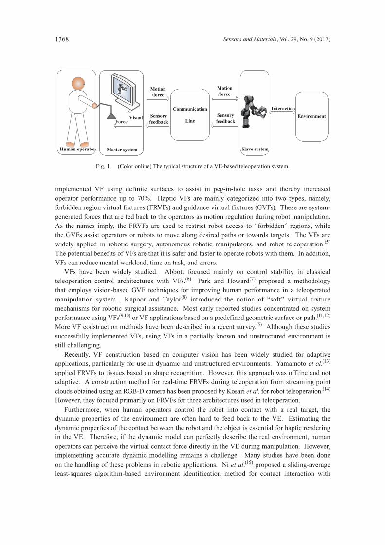
Robot teleoperation technology based on virtual environment (VE) is one of the most persuasive solutions currently employed to address the time delay problem in space teleoperation.(1–3) The entire VE-based teleoperation process is composed primarily of five modules: the human operator, the master system, the communication line, the slave robot system, and the real environment, as shown in Fig. 1. The slave robot and the real environment are modeled in the VE of the master system. The human operator controls the virtual robot through human–robot interaction (HRI) devices, such as the PHANToM Desktop, the Novint Falcon, and data gloves. The command for controlling the virtual robot is synchronously sent to the slave robot system through the communication line to control the slave robot. As humans are in the control loop, many uncertain aspects, such as disparity, precision in hand manipulations, and hand trembling, may affect the performance of systems. Most of these issues can be resolved through the application of a haptic virtual fixture in the VE. The virtual fixture (VF) theory was first proposed by Rosenberg as an overlay of abstract sensory information on a workspace to improve human performance in direct and remotely manipulated tasks.(4) He
1368 Sensors and Materials, Vol. 29, No. 9 (2017)
implemented VF using definite surfaces to assist in peg-in-hole tasks and thereby increased operator performance up to 70%. Haptic VFs are mainly categorized into two types, namely, forbidden region virtual fixtures (FRVFs) and guidance virtual fixtures (GVFs). These are system-generated forces that are fed back to the operators as motion regulation during robot manipulation. As the names imply, the FRVFs are used to restrict robot access to “forbidden” regions, while the GVFs assist operators or robots to move along desired paths or towards targets. The VFs are widely applied in robotic surgery, autonomous robotic manipulators, and robot teleoperation.(5) The potential benefits of VFs are that it is safer and faster to operate robots with them. In addition, VFs can reduce mental workload, time on task, and errors. VFs have been widely studied. Abbott focused mainly on control stability in classical teleoperation control architectures with VFs.(6) Park and Howard(7) proposed a methodology that employs vision-based GVF techniques for improving human performance in a teleoperated manipulation system. Kapoor and Taylor(8) introduced the notion of “soft” virtual fixture mechanisms for robotic surgical assistance. Most early reported studies concentrated on system performance using VFs(9,10) or VF applications based on a predefined geometric surface or path.(11,12) More VF construction methods have been described in a recent survey.(5) Although these studies successfully implemented VFs, using VFs in a partially known and unstructured environment is still challenging. Recently, VF construction based on computer vision has been widely studied for adaptive applications, particularly for use in dynamic and unstructured environments. Yamamoto et al.(13) applied FRVFs to tissues based on shape recognition. However, this approach was offline and not adaptive. A construction method for real-time FRVFs during teleoperation from streaming point clouds obtained using an RGB-D camera has been proposed by Kosari et al. for robot teleoperation.(14) However, they focused primarily on FRVFs for three architectures used in teleoperation. Furthermore, when human operators control the robot into contact with a real target, the dynamic properties of the environment are often hard to feed back to the VE. Estimating the dynamic properties of the contact between the robot and the object is essential for haptic rendering in the VE. Therefore, if the dynamic model can perfectly describe the real environment, human operators can perceive the virtual contact force directly in the VE during manipulation. However, implementing accurate dynamic modelling remains a challenge. Many studies have been done on the handling of these problems in robotic applications. Ni et al.(15) proposed a sliding-average least-squares algorithm-based environment identification method for contact interaction with
Fig. 1. (Color online) The typical structure of a VE-based teleoperation system.
Environment
Master systemHuman operator
Motion/force
Communication
Line
Motion/force
InteractionSensoryfeedback
Sensoryfeedback
Slave system
ForceVisual
Sensors and Materials, Vol. 29, No. 9 (2017) 1369
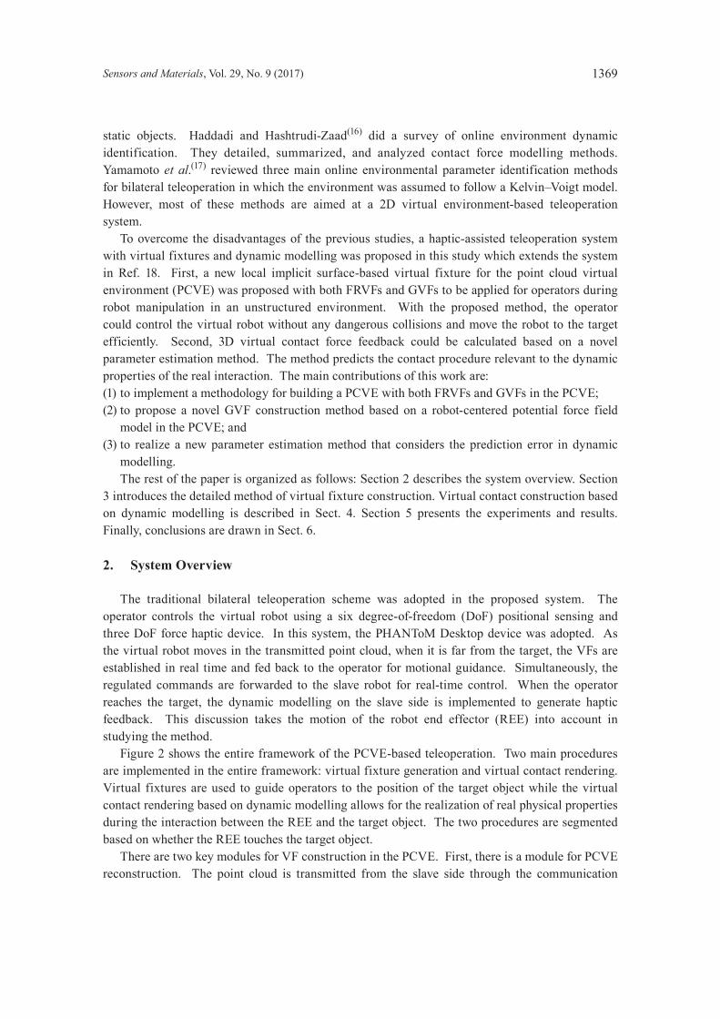
static objects. Haddadi and Hashtrudi-Zaad(16) did a survey of online environment dynamic identification. They detailed, summarized, and analyzed contact force modelling methods. Yamamoto et al.(17) reviewed three main online environmental parameter identification methods for bilateral teleoperation in which the environment was assumed to follow a Kelvin–Voigt model. However, most of these methods are aimed at a 2D virtual environment-based teleoperation system. To overcome the disadvantages of the previous studies, a haptic-assisted teleoperation system with virtual fixtures and dynamic modelling was proposed in this study which extends the system in Ref. 18. First, a new local implicit surface-based virtual fixture for the point cloud virtual environment (PCVE) was proposed with both FRVFs and GVFs to be applied for operators during robot manipulation in an unstructured environment. With the proposed method, the operator could control the virtual robot without any dangerous collisions and move the robot to the target efficiently. Second, 3D virtual contact force feedback could be calculated based on a novel parameter estimation method. The method predicts the contact procedure relevant to the dynamic properties of the real interaction. The main contributions of this work are:(1) to implement a methodology for building a PCVE with both FRVFs and GVFs in the PCVE;(2) to propose a novel GVF construction method based on a robot-centered potential force field
model in the PCVE; and(3) to realize a new parameter estimation method that considers the prediction error in dynamic
modelling. The rest of the paper is organized as follows: Section 2 describes the system overview. Section 3 introduces the detailed method of virtual fixture construction. Virtual contact construction based on dynamic modelling is described in Sect. 4. Section 5 presents the experiments and results. Finally, conclusions are drawn in Sect. 6.
2. System Overview
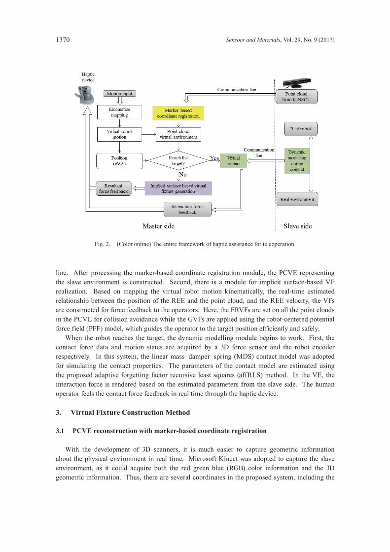
The traditional bilateral teleoperation scheme was adopted in the proposed system. The operator controls the virtual robot using a six degree-of-freedom (DoF) positional sensing and three DoF force haptic device. In this system, the PHANToM Desktop device was adopted. As the virtual robot moves in the transmitted point cloud, when it is far from the target, the VFs are established in real time and fed back to the operator for motional guidance. Simultaneously, the regulated commands are forwarded to the slave robot for real-time control. When the operator reaches the target, the dynamic modelling on the slave side is implemented to generate haptic feedback. This discussion takes the motion of the robot end effector (REE) into account in studying the method. Figure 2 shows the entire framework of the PCVE-based teleoperation. Two main procedures are implemented in the entire framework: virtual fixture generation and virtual contact rendering. Virtual fixtures are used to guide operators to the position of the target object while the virtual contact rendering based on dynamic modelling allows for the realization of real physical properties during the interaction between the REE and the target object. The two procedures are segmented based on whether the REE touches the target object. There are two key modules for VF construction in the PCVE. First, there is a module for PCVE reconstruction. The point cloud is transmitted from the slave side through the communication
1370 Sensors and Materials, Vol. 29, No. 9 (2017)
line. After processing the marker-based coordinate registration module, the PCVE representing the slave environment is constructed. Second, there is a module for implicit surface-based VF realization. Based on mapping the virtual robot motion kinematically, the real-time estimated relationship between the position of the REE and the point cloud, and the REE velocity, the VFs are constructed for force feedback to the operators. Here, the FRVFs are set on all the point clouds in the PCVE for collision avoidance while the GVFs are applied using the robot-centered potential force field (PFF) model, which guides the operator to the target position efficiently and safely. When the robot reaches the target, the dynamic modelling module begins to work. First, the contact force data and motion states are acquired by a 3D force sensor and the robot encoder respectively. In this system, the linear mass–damper–spring (MDS) contact model was adopted for simulating the contact properties. The parameters of the contact model are estimated using the proposed adaptive forgetting factor recursive least squares (affRLS) method. In the VE, the interaction force is rendered based on the estimated parameters from the slave side. The human operator feels the contact force feedback in real time through the haptic device.
3. Virtual Fixture Construction Method
3.1 PCVE reconstruction with marker-based coordinate registration
With the development of 3D scanners, it is much easier to capture geometric information about the physical environment in real time. Microsoft Kinect was adopted to capture the slave environment, as it could acquire both the red green blue (RGB) color information and the 3D geometric information. Thus, there are several coordinates in the proposed system, including the
Fig. 2. (Color online) The entire framework of haptic assistance for teleoperation.
Sensors and Materials, Vol. 29, No. 9 (2017) 1371
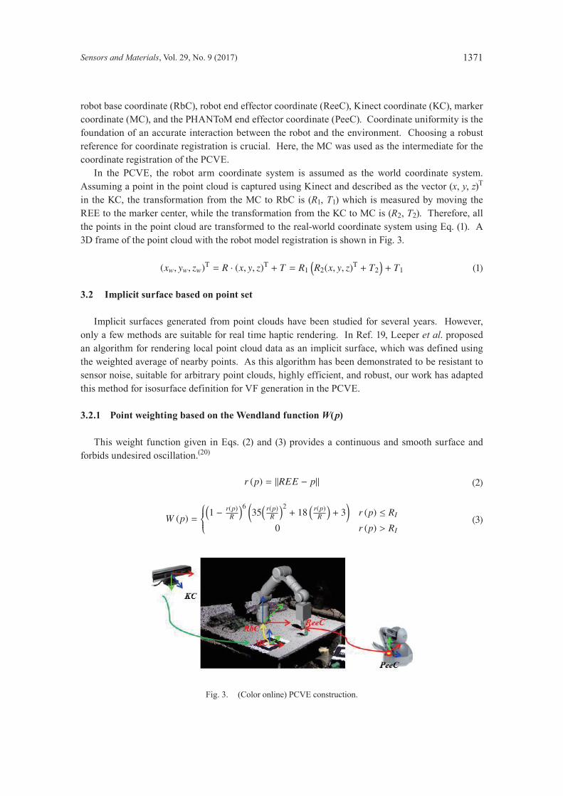
robot base coordinate (RbC), robot end effector coordinate (ReeC), Kinect coordinate (KC), marker coordinate (MC), and the PHANToM end effector coordinate (PeeC). Coordinate uniformity is the foundation of an accurate interaction between the robot and the environment. Choosing a robust reference for coordinate registration is crucial. Here, the MC was used as the intermediate for the coordinate registration of the PCVE. In the PCVE, the robot arm coordinate system is assumed as the world coordinate system. Assuming a point in the point cloud is captured using Kinect and described as the vector (x, y, z)T in the KC, the transformation from the MC to RbC is (R1, T1) which is measured by moving the REE to the marker center, while the transformation from the KC to MC is (R2, T2). Therefore, all the points in the point cloud are transformed to the real-world coordinate system using Eq. (1). A 3D frame of the point cloud with the robot model registration is shown in Fig. 3.
(xw, yw, zw)T = R · (x, y, z)T + T = R1(R2(x, y, z)T + T2
)+ T1 (1)
3.2 Implicit surface based on point set
Implicit surfaces generated from point clouds have been studied for several years. However, only a few methods are suitable for real time haptic rendering. In Ref. 19, Leeper et al. proposed an algorithm for rendering local point cloud data as an implicit surface, which was defined using the weighted average of nearby points. As this algorithm has been demonstrated to be resistant to sensor noise, suitable for arbitrary point clouds, highly efficient, and robust, our work has adapted this method for isosurface definition for VF generation in the PCVE.
3.2.1 Point weighting based on the Wendland function W(p)
This weight function given in Eqs. (2) and (3) provides a continuous and smooth surface and forbids undesired oscillation.(20)
r (p) = ‖REE − p‖ (2)
W (p) =
(1 − r(p)
R
)6 (35(
r(p)R
)2+ 18
(r(p)
R
)+ 3)
r (p) ≤ RI
0 r (p) > RI (3)
Fig. 3. (Color online) PCVE construction.

1372 Sensors and Materials, Vol. 29, No. 9 (2017)
The term r(p) represents the distance between the REE and the sensed points, and RI is the preset influence radius of the local area.
3.3.2 Point-setimplicitsurfacedefinition
As suggested in Ref. 20, limited by RI, the points surrounding the REE position can be obtained. For the REE location, the weighted average center of the point series is defined as ep, while the weighted average normal is defined as en in Eqs. (4) and (5), respectively.
ep = (x, y, z)T =
∑i
W (pi) pi (x, y, z)T
∑i
W(pi)
(4)
en = (x, y, z)T =
∑i
Wi (pi)(REE (x, y, z)T − pi (x, y, z)T
)∥∥∥∥∥∥∑i
Wi (pi)(REE (x, y, z)T − pi (x, y, z)T
)∥∥∥∥∥∥
(5)
Therefore, the relative implicit surface is described as
f (p) = enT (p − ep){px in Xlim, py in Ylim, pz in Zlim
}. (6)
iso (p) = f (p). (7)
In Eq. (6), f(p) = 0 is the implicit surface of a local region. Equation (7) is introduced as the isosurface function of the local implicit surface which describes a distance far from the local implicit surface.
3.3 FRVF
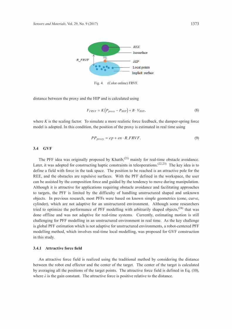
In the proposed system, the FRVF is defined on the upper boundary of the local point cloud by setting an isosurface that extends the implicit surface method in the whole point cloud environment. Thus, the local manipulation region is protected from dangerous collisions. As shown in Fig. 4, the blue points are the local points in the point cloud when the virtual robot moves, while the blue plane represents the simulated local implicit surface. Meanwhile, the purple ball represents the REE position, and the green plane shows the relative isosurface R_FRVF distant from the local surface. In the virtual environment, the haptic interface point (HIP) represents the motion of the haptic device end effector. To achieve a collision-free system, the proxy represents the position of the virtual robot REE. Here, Rf is set as the local surface detection area limitation. When no points appear in the Rf region, the proxy tracks the HIP position, and the virtual robot moves in a free space. Once there are some points in the Rf area, the implicit surface is simulated accordingly. Meanwhile, FRVFs work to avoid collisions. The feedback force is linear with respect to the
Sensors and Materials, Vol. 29, No. 9 (2017) 1373
distance between the proxy and the HIP and is calculated using
FFRVF = K(Pproxy − PHIP
)+ B · VHIP, (8)
where K is the scaling factor. To simulate a more realistic force feedback, the damper-spring force model is adopted. In this condition, the position of the proxy is estimated in real time using
PPproxy = ep + en · R FRVF. (9)
3.4 GVF
The PFF idea was originally proposed by Khatib,(21) mainly for real-time obstacle avoidance. Later, it was adopted for constructing haptic constraints in teleoperations.(22,23) The key idea is to define a field with force in the task space. The position to be reached is an attractive pole for the REE, and the obstacles are repulsive surfaces. With the PFF defined in the workspace, the user can be assisted by the composition force and guided by the tendency to move during manipulation. Although it is attractive for applications requiring obstacle avoidance and facilitating approaches to targets, the PFF is limited by the difficulty of handling unstructured shaped and unknown objects. In previous research, most PFFs were based on known simple geometrics (cone, curve, cylinder), which are not adaptive for an unstructured environment. Although some researchers tried to optimize the performance of PFF modelling with arbitrarily shaped objects,(24) that was done offline and was not adaptive for real-time systems. Currently, estimating motion is still challenging for PFF modelling in an unstructured environment in real time. As the key challenge is global PFF estimation which is not adaptive for unstructured environments, a robot-centered PFF modelling method, which involves real-time local modelling, was proposed for GVF construction in this study.
3.4.1 Attractiveforcefield
An attractive force field is realized using the traditional method by considering the distance between the robot end effector and the center of the target. The center of the target is calculated by averaging all the positions of the target points. The attractive force field is defined in Eq. (10), where λ is the gain constant. The attractive force is positive relative to the distance.
Fig. 4. (Color online) FRVF.
1374 Sensors and Materials, Vol. 29, No. 9 (2017)
Uatt =12λ(PTC − pREE)2 (10)
Meanwhile, the attractive force value is calculated using Eq. (11).
U′att = λ (PTC − pREE) (11)
The attractive force direction is towards the target center, which is estimated based on the target points.
3.4.2 Repulsiveforcefield
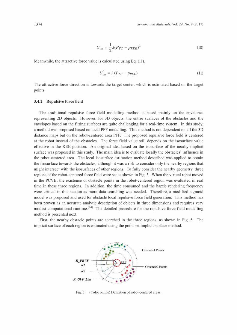
The traditional repulsive force field modelling method is based mainly on the envelopes representing 2D objects. However, for 3D objects, the entire surfaces of the obstacles and the envelopes based on the fitting surfaces are quite challenging for a real-time system. In this study, a method was proposed based on local PFF modelling. This method is not dependent on all the 3D distance maps but on the robot-centered area PFF. The proposed repulsive force field is centered at the robot instead of the obstacles. The force field value still depends on the isosurface value effective in the REE position. An original idea based on the isosurface of the nearby implicit surface was proposed in this study. The main idea is to evaluate locally the obstacles’ influence in the robot-centered area. The local isosurface estimation method described was applied to obtain the isosurface towards the obstacles, although it was a risk to consider only the nearby regions that might intersect with the isosurfaces of other regions. To fully consider the nearby geometry, three regions of the robot-centered force field were set as shown in Fig. 5. When the virtual robot moved in the PCVE, the existence of obstacle points in the robot-centered region was evaluated in real time in these three regions. In addition, the time consumed and the haptic rendering frequency were critical in this section as more data searching was needed. Therefore, a modified sigmoid model was proposed and used for obstacle local repulsive force field generation. This method has been proven as an accurate analytic description of objects in three dimensions and requires very modest computational runtime.(24) The detailed procedure for the repulsive force field modelling method is presented next. First, the nearby obstacle points are searched in the three regions, as shown in Fig. 5. The implicit surface of each region is estimated using the point set implicit surface method.
Fig.5. (Coloronline)Definitionofrobot-centeredareas.
Sensors and Materials, Vol. 29, No. 9 (2017) 1375
Second, the isosurface value at the REE position of each surface is analyzed using the sigmoid model as shown in Eq. (12).
Urep (q) =1
1 + eγ∗|iso(q)| , (12)
where iso(q) is the estimated isosurface at the REE position q. Using this equation, the repulsive force field can be calculated. In some circumstances, such as moving a robot away from obstacles and remaining static, applying a repulsive force on the operator leads to a massive workload for the operators. It is essential to consider the velocity before applying force feedback. Therefore, the direction of the velocity relative to the obstacles is considered in the resultant force calculation. Third, by combining the velocity factors with the sigmoid model, the repulsive force field value is generated and the resultant repulsive force magnitude and direction are calculated assuming the gradient of the Urep at the REE position is dt, and the velocity of REE is v. If dt●v≥0, theREEremainsstaticormovesawayfromthecurrentobstaclesurface,andtherepulsive force is zero. When dt●v < 0, the motion of REE is towards the local obstacle, and the repulsive force is in effect. Finally, the resultant force from the potential force field is the sum of the repulsive force and the attractive force. However, as the resultant force is fed back to the haptic device, it may exceed the hardware output; a magnitude adjustment parameter AF is adopted in practical applications. Therefore, the guidance constraint is defined by Eq. (13).
FGVF = AF(U′rep + U
′att
) (13)
4. Virtual Contact Based on Dynamic Modelling
During the contact between two objects, the bodies suffer elastic and/or plastic deformation with loss of energy in various forms. As the MDS model allows more modelling freedoms with linearity properties, it is widely used in contact simulations. Thus, in the proposed system, we adopted the MDS model for contact dynamic modelling. In the teleoperation system, real-time parameter estimation is essential because any parameter error can lead to bad modelling. The ability to track abrupt changes during operation is vital. In previous teleoperation systems, the block-wise sliding least squares (BSLS) method(3) has been used. Even though the tracking performance is relatively good, the computational complexity is on the order of O(N3) which grows as block size increases. The exponentially weighted recursive least squares (EWRLS) estimation method has been proven to have lower computational complexity on the order of O(N2). However, it cannot adaptively change the weight, which better tracks the abrupt changes of values. In this study, we propose a novel affRLS method for online parameter estimation which adaptively adjusts the forgetting factor for balancing previous data contributions. The measured force described by the MDS model is shown by Eq. (14):
fcontact = mx + bx + kx + ε, (14)
where ε is the measured noise. Let θ =[m b k
]T, φ =
[x x x
]T, Y (t) = fcontact, then,
Y (t) = θTφ + ε. The basic EWRLS equations are as follows.
1376 Sensors and Materials, Vol. 29, No. 9 (2017)
θ (n) = θ (n − 1) + k (n)(Y (n) − θT (n − 1) φ (n)
) (15)
k(n) =P(n − 1)φ(n)
λ + φT(n)P(n − 1)φ(n) (16)
P(n) = λ−1(P(n − 1) − k(n)φT(n)P(n − 1)
) (17)
Here, n is the time index in the discrete domain, P is the covariance matrix, and λ (0 < λ ≤ 1) is the forgetting factor. The larger the λ, the less important the influence of old data. Meanwhile, the estimated parameters can be calculated from θ (n) =
[m (n) b (n) k (n)
]T. The EWRLS method
has been proven to be effective and accurate for parameter estimation and robust against data noise. However, there are still two problems in using the EWRLS method:(16) (1) it is not adaptive for tracking changes after convergence, and (2) the initial values still affect the convergence rate. The affRLS method was proposed to counter the problems with the EWRLS method by adaptively modifying the value of the forgetting factors. A change detect theory was applied to detect parameter changes. The prediction error of a preset length window in the neighbor region is calculated using Eq. (18):
e (k) = Ykk−L+1 − Yk
k−L+1 = Ykk−L+1 − φ
kk−L+1θL (k), (18)
where L is the neighbor window length, Ykk−L+1 =
[Y (k − L + 1) Y (k − L) . . . Y (k)
]. The
forgetting factor must change if the average value E = eTe/L exceeds a set threshold β. In this system, β = (4–6) × Var{e(k)}. The detailed affRLS algorithm is presented as follows.
Algorithm Adaptive Forgetting Factor RLS (LIST Y, LIST X, λ)1: θc = EWRLS (Y, X, λ)2: for k−L+1 < i < k3: e(i) = Y(i)−θc'φ(i)4: end for 5: E = e'e/L6: if E > β7: λ = 0.98: else if λ < 0.989: λ = λ + 0.08/L;10: else λ = 0.98 11: end if12: end if
5. Experiments
5.1 System setup
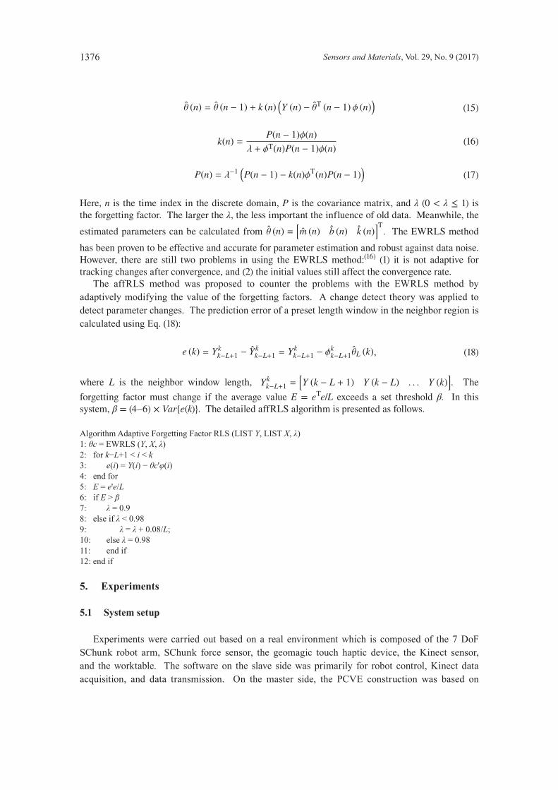
Experiments were carried out based on a real environment which is composed of the 7 DoF SChunk robot arm, SChunk force sensor, the geomagic touch haptic device, the Kinect sensor, and the worktable. The software on the slave side was primarily for robot control, Kinect data acquisition, and data transmission. On the master side, the PCVE construction was based on
Sensors and Materials, Vol. 29, No. 9 (2017) 1377
VS2010, the PCL library, and the OpenCV library while OpenGL was used to render the 3D graphics. The computers worked at 3.2 GHz. The experimental setup is shown in Fig. 6.
5.2 Evaluationofvirtualfixtures
5.2.1 Evaluation of task implementation
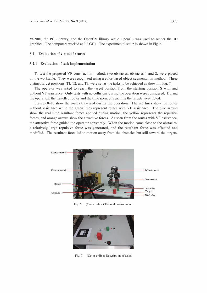
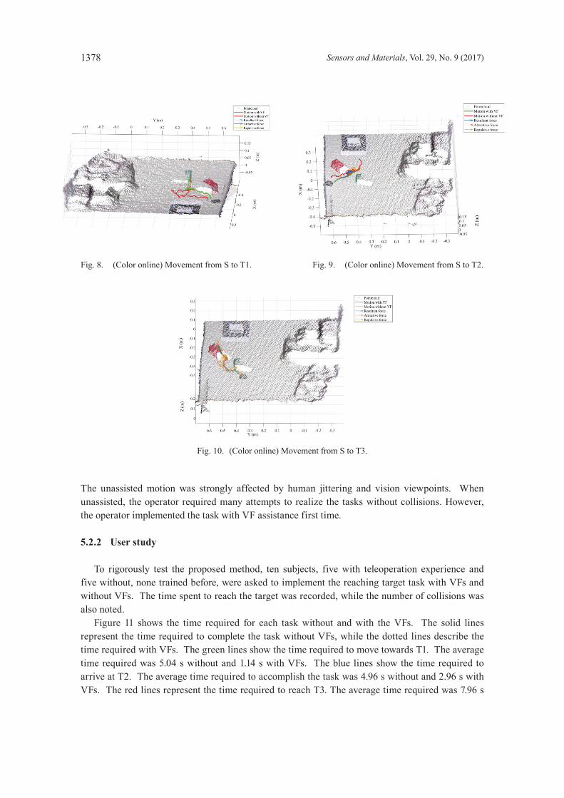
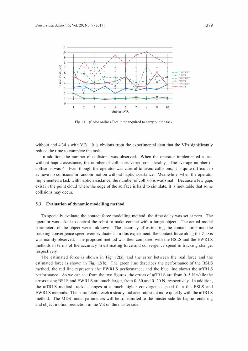
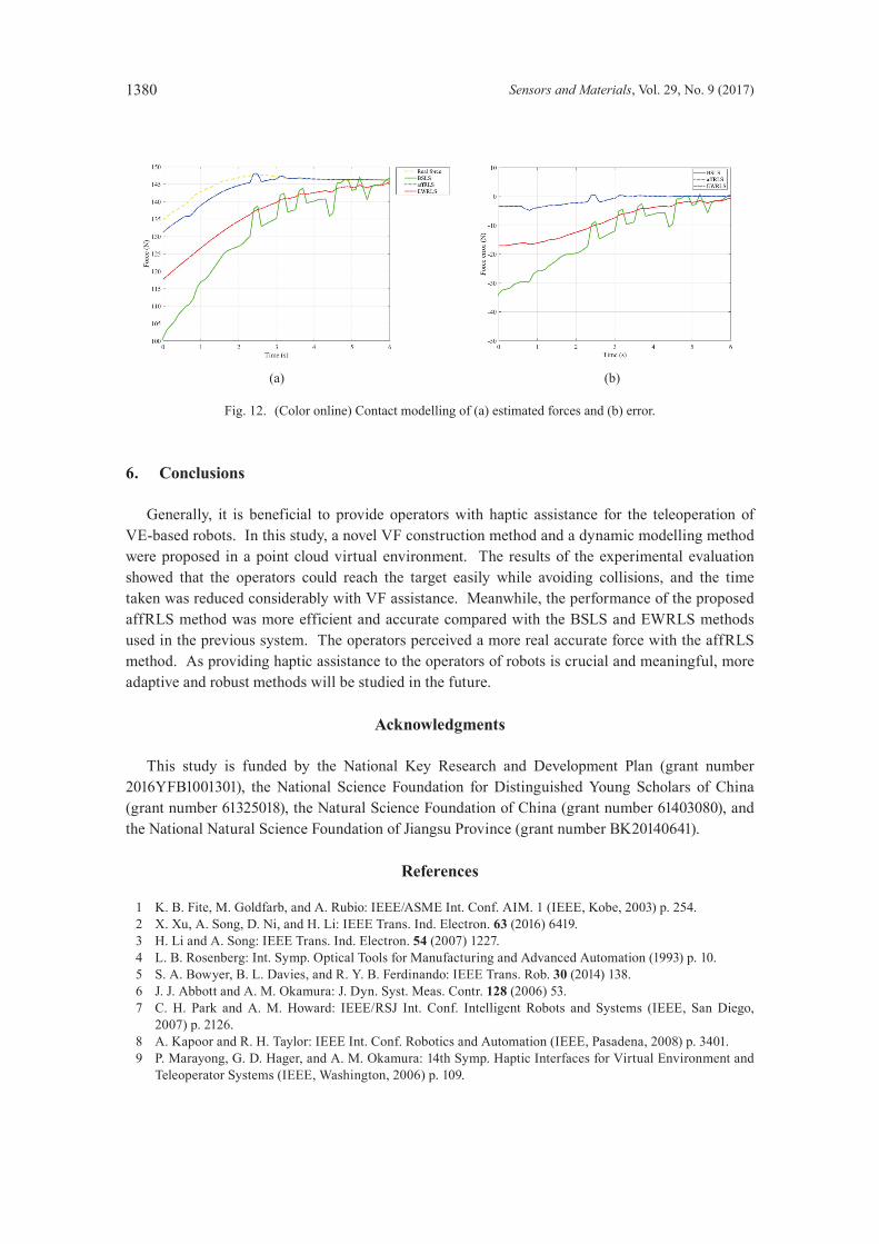
To test the proposed VF construction method, two obstacles, obstacles 1 and 2, were placed on the worktable. They were recognized using a color-based object segmentation method. Three distinct target positions, T1, T2, and T3, were set as the tasks to be achieved as shown in Fig. 7. The operator was asked to reach the target position from the starting position S with and without VF assistance. Only tests with no collisions during the operation were considered. During the operation, the travelled routes and the time spent on reaching the targets were noted. Figures 8–10 show the routes traversed during the operation. The red lines show the routes without assistance while the green lines represent routes with VF assistance. The blue arrows show the real time resultant forces applied during motion, the yellow represents the repulsive forces, and orange arrows show the attractive forces. As seen from the routes with VF assistance, the attractive force guided the operator constantly. When the motion came close to the obstacles, a relatively large repulsive force was generated, and the resultant force was affected and modified. The resultant force led to motion away from the obstacles but still toward the targets.
Fig. 6. (Color online) The real environment.
Fig. 7. (Color online) Description of tasks.
1378 Sensors and Materials, Vol. 29, No. 9 (2017)
The unassisted motion was strongly affected by human jittering and vision viewpoints. When unassisted, the operator required many attempts to realize the tasks without collisions. However, the operator implemented the task with VF assistance first time.
5.2.2 User study
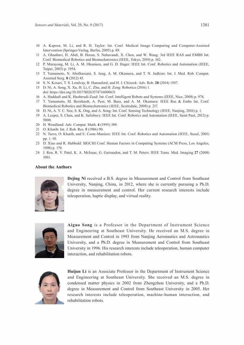
To rigorously test the proposed method, ten subjects, five with teleoperation experience and five without, none trained before, were asked to implement the reaching target task with VFs and without VFs. The time spent to reach the target was recorded, while the number of collisions was also noted. Figure 11 shows the time required for each task without and with the VFs. The solid lines represent the time required to complete the task without VFs, while the dotted lines describe the time required with VFs. The green lines show the time required to move towards T1. The average time required was 5.04 s without and 1.14 s with VFs. The blue lines show the time required to arrive at T2. The average time required to accomplish the task was 4.96 s without and 2.96 s with VFs. The red lines represent the time required to reach T3. The average time required was 7.96 s
Fig. 10. (Color online) Movement from S to T3.
Fig. 8. (Color online) Movement from S to T1. Fig. 9. (Color online) Movement from S to T2.
Sensors and Materials, Vol. 29, No. 9 (2017) 1379
without and 4.34 s with VFs. It is obvious from the experimental data that the VFs significantly reduce the time to complete the task. In addition, the number of collisions was observed. When the operator implemented a task without haptic assistance, the number of collisions varied considerably. The average number of collisions was 4. Even though the operator was careful to avoid collisions, it is quite difficult to achieve no collisions in random motion without haptic assistance. Meanwhile, when the operator implemented a task with haptic assistance, the number of collisions was small. Because a few gaps exist in the point cloud where the edge of the surface is hard to simulate, it is inevitable that some collisions may occur.
5.3 Evaluation of dynamic modelling method
To specially evaluate the contact force modelling method, the time delay was set at zero. The operator was asked to control the robot to make contact with a target object. The actual model parameters of the object were unknown. The accuracy of estimating the contact force and the tracking convergence speed were evaluated. In this experiment, the contact force along the Z axis was mainly observed. The proposed method was then compared with the BSLS and the EWRLS methods in terms of the accuracy in estimating force and convergence speed in tracking change, respectively. The estimated force is shown in Fig. 12(a), and the error between the real force and the estimated force is shown in Fig. 12(b). The green line describes the performance of the BSLS method, the red line represents the EWRLS performance, and the blue line shows the affRLS performance. As we can see from the two figures, the errors of affRLS are from 0–5 N while the errors using BSLS and EWRLS are much larger, from 0–30 and 0–20 N, respectively. In addition, the affRLS method tracks changes at a much higher convergence speed than the BSLS and EWRLS methods. The parameters reach a steady and accurate state more quickly with the affRLS method. The MDS model parameters will be transmitted to the master side for haptic rendering and object motion prediction in the VE on the master side.
0123456789
1011
1 2 3 4 5 6 7 8 9 10
)ceS( tsoC e
miT
Subject NO.
T1/WITHOUTT1/WITHT2/WITHOUTT2/WITHT3/WITHOUTT3/WITH
Fig. 11. (Color online) Total time required to carry out the task.
1380 Sensors and Materials, Vol. 29, No. 9 (2017)
6. Conclusions
Generally, it is beneficial to provide operators with haptic assistance for the teleoperation of VE-based robots. In this study, a novel VF construction method and a dynamic modelling method were proposed in a point cloud virtual environment. The results of the experimental evaluation showed that the operators could reach the target easily while avoiding collisions, and the time taken was reduced considerably with VF assistance. Meanwhile, the performance of the proposed affRLS method was more efficient and accurate compared with the BSLS and EWRLS methods used in the previous system. The operators perceived a more real accurate force with the affRLS method. As providing haptic assistance to the operators of robots is crucial and meaningful, more adaptive and robust methods will be studied in the future.
Acknowledgments
This study is funded by the National Key Research and Development Plan (grant number 2016YFB1001301), the National Science Foundation for Distinguished Young Scholars of China (grant number 61325018), the Natural Science Foundation of China (grant number 61403080), and the National Natural Science Foundation of Jiangsu Province (grant number BK20140641).
References
1 K. B. Fite, M. Goldfarb, and A. Rubio: IEEE/ASME Int. Conf. AIM. 1 (IEEE, Kobe, 2003) p. 254. 2 X. Xu, A. Song, D. Ni, and H. Li: IEEE Trans. Ind. Electron. 63 (2016) 6419. 3 H. Li and A. Song: IEEE Trans. Ind. Electron. 54 (2007) 1227. 4 L. B. Rosenberg: Int. Symp. Optical Tools for Manufacturing and Advanced Automation (1993) p. 10. 5 S. A. Bowyer, B. L. Davies, and R. Y. B. Ferdinando: IEEE Trans. Rob. 30 (2014) 138. 6 J. J. Abbott and A. M. Okamura: J. Dyn. Syst. Meas. Contr. 128 (2006) 53. 7 C. H. Park and A. M. Howard: IEEE/RSJ Int. Conf. Intelligent Robots and Systems (IEEE, San Diego,
2007) p. 2126. 8 A. Kapoor and R. H. Taylor: IEEE Int. Conf. Robotics and Automation (IEEE, Pasadena, 2008) p. 3401. 9 P. Marayong, G. D. Hager, and A. M. Okamura: 14th Symp. Haptic Interfaces for Virtual Environment and
Teleoperator Systems (IEEE, Washington, 2006) p. 109.
Fig. 12. (Color online) Contact modelling of (a) estimated forces and (b) error.
(a) (b)
Sensors and Materials, Vol. 29, No. 9 (2017) 1381
10 A. Kapoor, M. Li, and R. H. Taylor: Int. Conf. Medical Image Computing and Computer-Assisted Intervention (Springer-Verlag, Berlin, 2005) p. 89.
11 A. Ghanbari, H. Abdi, B. Horan, S. Nahavandi, X. Chen, and W. Wang: 3rd IEEE RAS and EMBS Int. Conf. Biomedical Robotics and Biomechatronics (IEEE, Tokyo, 2010) p. 162.
12 P. Marayong, M. Li, A. M. Okamura, and G. D. Hager: IEEE Int. Conf. Robotics and Automation (IEEE, Taipei, 2003) p. 1954.
13 T. Yamamoto, N. Abolhassani, S. Jung, A. M. Okamura, and T. N. Judkins: Int. J. Med. Rob. Comput. Assisted Surg. 8 (2012) 45.
14 S. N. Kosari, T. S. Lendvay, B. Hannaford, and H. J. Chizeck: Adv. Rob. 28 (2014) 1507. 15 D. Ni, A. Song, X. Xu, H. Li, C. Zhu, and H. Zeng: Robotica (2016) 1. doi: https://doi.org/10.1017/S0263574716000631 16 A. Haddadi and K. Hashtrudi-Zaad: Int. Conf. Intelligent Robots and Systems (IEEE, Nice, 2008) p. 974. 17 T. Yamamoto, M. Bernhardt, A. Peer, M. Buss, and A. M. Okamura: IEEE Ras & Embs Int. Conf.
Biomedical Robotics and Biomechatronics (IEEE, Scottsdale, 2008) p. 217. 18 D. Ni, A. Y. C. Nee, S. K. Ong, and A. Song: Int. Conf. Sensing Technology (IEEE, Nanjing, 2016) p. 1. 19 A. Leeper, S. Chan, and K. Salisbury: IEEE Int. Conf. Robotics and Automation (IEEE, Saint Paul, 2012) p.
5000. 20 H. Wendland: Adv. Comput. Math. 4 (1995) 389. 21 O. Khatib: Int. J. Rob. Res. 5 (1986) 90. 22 N. Turro, O. Khatib, and E. Coste-Maniere: IEEE Int. Conf. Robotics and Automation (IEEE, Seoul, 2001)
pp. 1–10. 23 D. Xiao and R. Hubbold: SIGCHI Conf. Human Factors in Computing Systems (ACM Press, Los Angeles,
1998) p. 179. 24 J. Ren, R. V. Patel, K. A. McIsaac, G. Guiraudon, and T. M. Peters: IEEE Trans. Med. Imaging 27 (2008)
1061.
About the Authors
Dejing Ni received a B.S. degree in Measurement and Control from Southeast University, Nanjing, China, in 2012, where she is currently pursuing a Ph.D. degree in measurement and control. Her current research interests include teleoperation, haptic display, and virtual reality.
Aiguo Song is a Professor in the Department of Instrument Science and Engineering at Southeast University. He received an M.S. degree in Measurement and Control in 1993 from Nanjing Aeronautics and Astronautics University, and a Ph.D. degree in Measurement and Control from Southeast University in 1996. His research interests include teleoperation, human computer interaction, and rehabilitation robots.
Huijun Li is an Associate Professor in the Department of Instrument Science and Engineering at Southeast University. She received an M.S. degree in condensed matter physics in 2002 from Zhengzhou University, and a Ph.D. degree in Measurement and Control from Southeast University in 2005. Her research interests include teleoperation, machine-human interaction, and rehabilitation robots.