
HANDI-MATE INSTALL GUIDE - Stratco...SLIDING DOOR HANDI-MATE INSTALLATION GUIDE HANDI-MATE SHED...
18
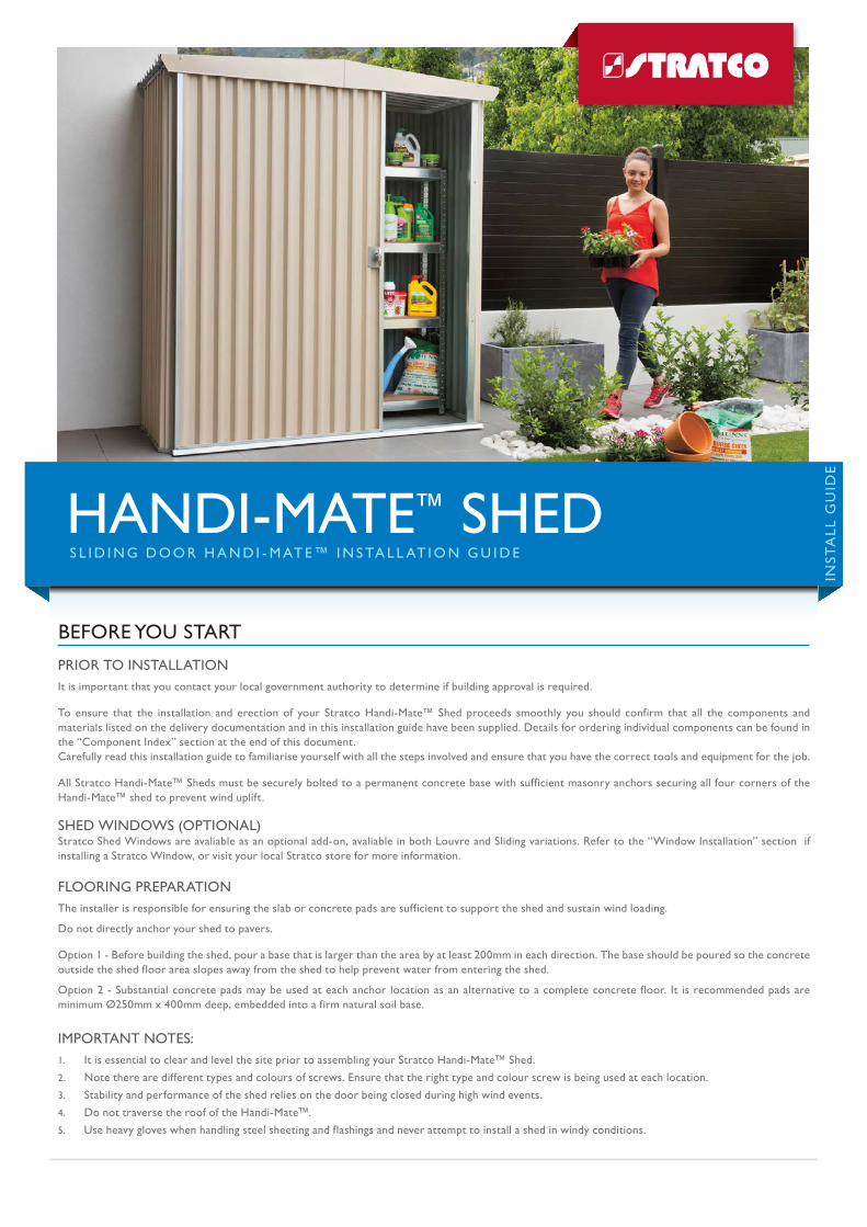
SLIDING DOOR HANDI-MATE™ INSTALLATION GUIDE HANDI-MATE ™ SHED INSTALL GUIDE PRIOR TO INSTALLATION It is important that you contact your local government authority to determine if building approval is required. To ensure that the installation and erection of your Stratco Handi-Mate™ Shed proceeds smoothly you should confirm that all the components and materials listed on the delivery documentation and in this installation guide have been supplied. Details for ordering individual components can be found in the “Component Index” section at the end of this document. Carefully read this installation guide to familiarise yourself with all the steps involved and ensure that you have the correct tools and equipment for the job. All Stratco Handi-Mate™ Sheds must be securely bolted to a permanent concrete base with sufficient masonry anchors securing all four corners of the Handi-Mate™ shed to prevent wind uplift. SHED WINDOWS (OPTIONAL) Stratco Shed Windows are avaliable as an optional add-on, avaliable in both Louvre and Sliding variations. Refer to the “Window Installation” section if installing a Stratco Window, or visit your local Stratco store for more information. FLOORING PREPARATION The installer is responsible for ensuring the slab or concrete pads are sufficient to support the shed and sustain wind loading. Do not directly anchor your shed to pavers. Option 1 - Before building the shed, pour a base that is larger than the area by at least 200mm in each direction. The base should be poured so the concrete outside the shed floor area slopes away from the shed to help prevent water from entering the shed. Option 2 - Substantial concrete pads may be used at each anchor location as an alternative to a complete concrete floor. It is recommended pads are minimum Ø250mm x 400mm deep, embedded into a firm natural soil base. IMPORTANT NOTES: 1. It is essential to clear and level the site prior to assembling your Stratco Handi-Mate™ Shed. 2. Note there are different types and colours of screws. Ensure that the right type and colour screw is being used at each location. 3. Stability and performance of the shed relies on the door being closed during high wind events. 4. Do not traverse the roof of the Handi-Mate™. 5. Use heavy gloves when handling steel sheeting and flashings and never attempt to install a shed in windy conditions. BEFORE YOU START
Transcript of HANDI-MATE INSTALL GUIDE - Stratco...SLIDING DOOR HANDI-MATE INSTALLATION GUIDE HANDI-MATE SHED...
S L I D I N G D O O R H A N D I - M AT E™ I N S TA L L AT I O N G U I D E
HANDI-MATE™ SHED
INST
ALL
GU
IDE
PRIOR TO INSTALLATION It is important that you contact your local government authority to determine if building approval is required.
To ensure that the installation and erection of your Stratco Handi-Mate™ Shed proceeds smoothly you should confirm that all the components and materials listed on the delivery documentation and in this installation guide have been supplied. Details for ordering individual components can be found in the “Component Index” section at the end of this document.Carefully read this installation guide to familiarise yourself with all the steps involved and ensure that you have the correct tools and equipment for the job.
All Stratco Handi-Mate™ Sheds must be securely bolted to a permanent concrete base with sufficient masonry anchors securing all four corners of the Handi-Mate™ shed to prevent wind uplift.
SHED WINDOWS (OPTIONAL)Stratco Shed Windows are avaliable as an optional add-on, avaliable in both Louvre and Sliding variations. Refer to the “Window Installation” section if installing a Stratco Window, or visit your local Stratco store for more information.
FLOORING PREPARATIONThe installer is responsible for ensuring the slab or concrete pads are sufficient to support the shed and sustain wind loading.
Do not directly anchor your shed to pavers.
Option 1 - Before building the shed, pour a base that is larger than the area by at least 200mm in each direction. The base should be poured so the concrete outside the shed floor area slopes away from the shed to help prevent water from entering the shed.
Option 2 - Substantial concrete pads may be used at each anchor location as an alternative to a complete concrete floor. It is recommended pads are minimum Ø250mm x 400mm deep, embedded into a firm natural soil base.
IMPORTANT NOTES:1. It is essential to clear and level the site prior to assembling your Stratco Handi-Mate™ Shed.
2. Note there are different types and colours of screws. Ensure that the right type and colour screw is being used at each location.
3. Stability and performance of the shed relies on the door being closed during high wind events.
4. Do not traverse the roof of the Handi-Mate™.
5. Use heavy gloves when handling steel sheeting and flashings and never attempt to install a shed in windy conditions.
BEFORE YOU START
2
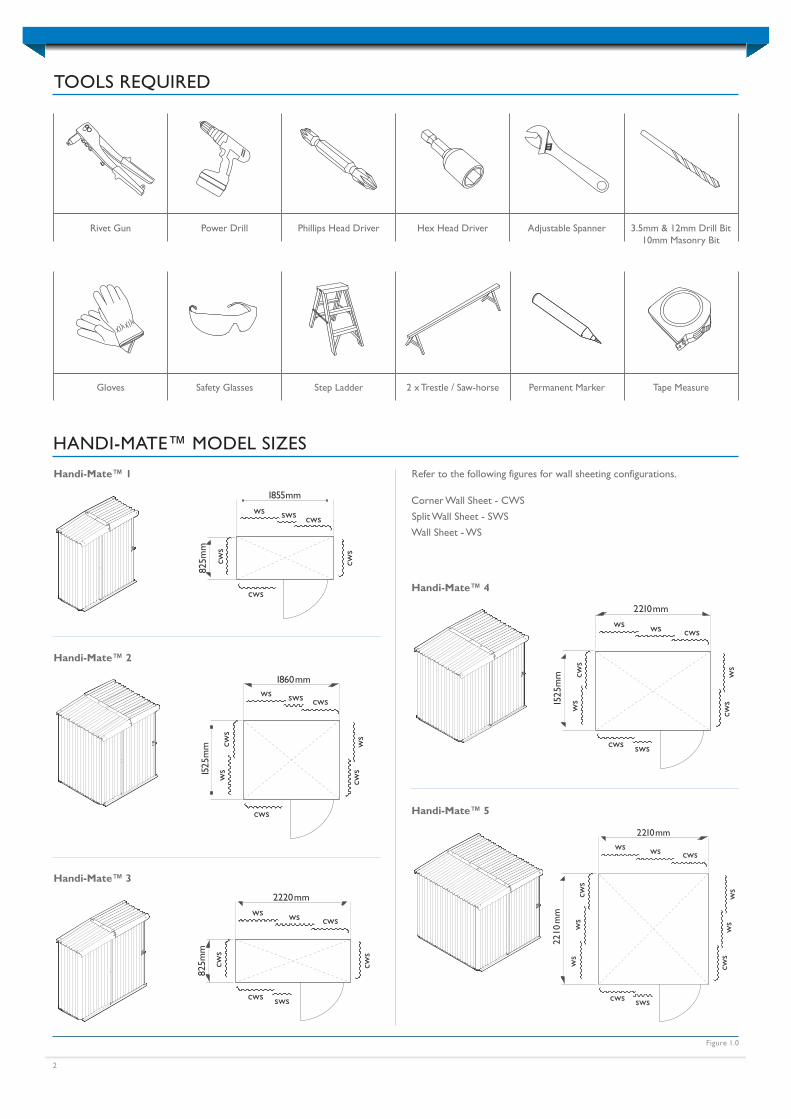
HANDI-MATE™ MODEL SIZES
1525
mm
825m
m
825m
m
1525
mm
2210
mm
825
1860 mm
1855mm 2220 mm
2210 mm
2210 mm
2900
ws sws cws
ws sws
cws
wscwsws
wscwsws
wscwsws
wscwsws
ws
cws
cws
ws
cws
cws
ws
cws
ws
ws
cwscw
sw
s
cws
ws
cws
ws
cws
ws
cwscws cws sws cws sws
cws sws
cws
csws sws
cws
1525
mm
825m
m
825m
m
1525
mm
2210
mm
825
1860 mm
1855mm 2220 mm
2210 mm
2210 mm
2900
ws sws cws
ws sws
cws
wscwsws
wscwsws
wscwsws
wscwsws
ws
cws
cws
ws
cws
cws
ws
cws
ws
ws
cwscw
sw
s
cws
ws
cws
ws
cws
ws
cwscws cws sws cws sws
cws sws
cws
csws sws
cws
1525
mm
825m
m
825m
m
1525
mm
2210
mm
825
1860 mm
1855mm 2220 mm
2210 mm
2210 mm
2900
ws sws cws
ws sws
cws
wscwsws
wscwsws
wscwsws
wscwsws
ws
cws
cws
ws
cws
cws
ws
cws
ws
ws
cwscw
sw
s
cws
ws
cws
ws
cws
ws
cwscws cws sws cws sws
cws sws
cws
csws sws
cws
Handi-Mate™ 1
1525
mm
825m
m
825m
m
1525
mm
2210
mm
825
1860 mm
1855mm 2220 mm
2210 mm
2210 mm
2900
ws sws cws
ws sws
cws
wscwsws
wscwsws
wscwsws
wscwsws
ws
cws
cws
ws
cws
cws
ws
cws
ws
ws
cwscw
sw
s
cws
ws
cws
ws
cws
ws
cwscws cws sws cws sws
cws sws
cws
csws sws
cws
Handi-Mate™ 2
1525
mm
825m
m
825m
m
1525
mm
2210
mm
825
1860 mm
1855mm 2220 mm
2210 mm
2210 mm
2900
ws sws cws
ws sws
cws
wscwsws
wscwsws
wscwsws
wscwsws
ws
cws
cws
ws
cws
cws
ws
cws
ws
ws
cwscw
sw
s
cws
ws
cws
ws
cws
ws
cwscws cws sws cws sws
cws sws
cws
csws swscw
s
Handi-Mate™ 3
Handi-Mate™ 4
Handi-Mate™ 5
TOOLS REQUIRED
Rivet Gun Power Drill Phillips Head Driver Hex Head Driver Adjustable Spanner 3.5mm & 12mm Drill Bit10mm Masonry Bit
Gloves Safety Glasses Step Ladder 2 x Trestle / Saw-horse Permanent Marker Tape Measure
Figure 1.0
Refer to the following figures for wall sheeting configurations.
Corner Wall Sheet - CWS
Split Wall Sheet - SWS
Wall Sheet - WS
3
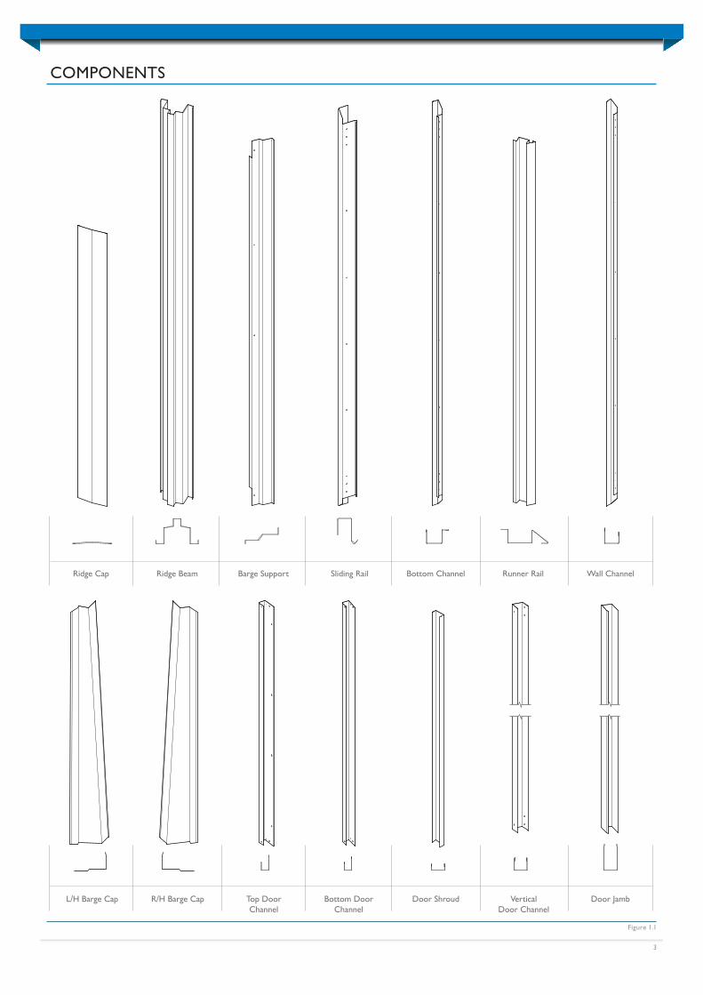
COMPONENTS
Figure 1.1
Ridge Cap Ridge Beam
Door Shroud
Barge Support Sliding Rail Bottom Channel Runner Rail Wall Channel
L/H Barge Cap R/H Barge Cap Top DoorChannel
Bottom DoorChannel
VerticalDoor Channel
Door Jamb
4
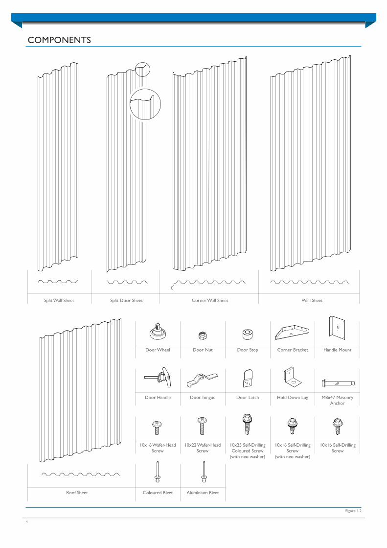
COMPONENTS
Figure 1.2
Split Wall Sheet Split Door Sheet Corner Wall Sheet Wall Sheet
Roof Sheet Coloured Rivet Aluminium Rivet
10x16 Wafer-Head Screw
10x22 Wafer-Head Screw
10x25 Self-Drilling Coloured Screw
(with neo washer)
10x16 Self-Drilling Screw
(with neo washer)
10x16 Self-Drilling Screw
Door Handle Door Tongue Door Latch Hold Down Lug M8x47 Masonry Anchor
Door Wheel Door Nut Door Stop Corner Bracket Handle Mount
5
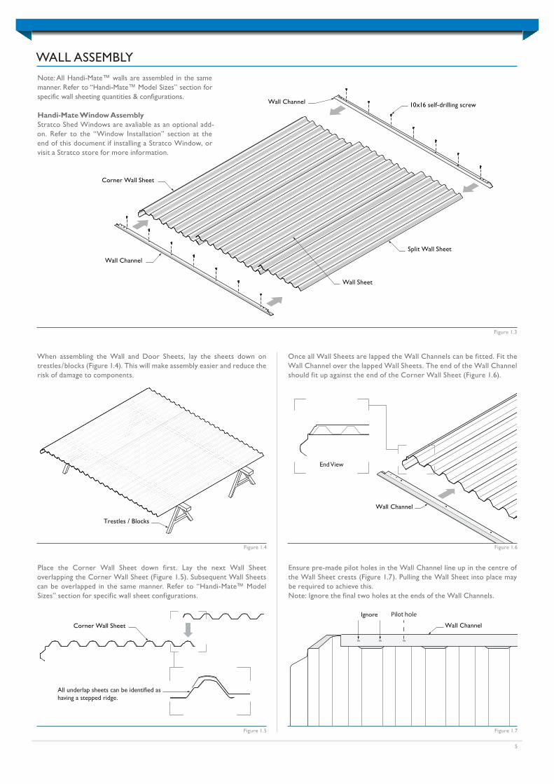
WALL ASSEMBLY
10x16 self-drilling screw
Wall Channel
Corner Wall Sheet
Split Wall Sheet
Wall Channel
Wall Sheet
Once all Wall Sheets are lapped the Wall Channels can be fitted. Fit the Wall Channel over the lapped Wall Sheets. The end of the Wall Channel should fit up against the end of the Corner Wall Sheet (Figure 1.6).
End View
Wall Channel
Figure 1.3
Note: All Handi-Mate™ walls are assembled in the same manner. Refer to “Handi-Mate™ Model Sizes” section for specific wall sheeting quantities & configurations.
Handi-Mate Window AssemblyStratco Shed Windows are avaliable as an optional add-on. Refer to the “Window Installation” section at the end of this document if installing a Stratco Window, or visit a Stratco store for more information.
Figure 1.6
When assembling the Wall and Door Sheets, lay the sheets down on trestles / blocks (Figure 1.4). This will make assembly easier and reduce the risk of damage to components.
All underlap sheets can be identified as having a stepped ridge.
Corner Wall Sheet
Trestles / Blocks
Figure 1.5
Figure 1.4
Ignore
Wall Channel
Pilot hole
Figure 1.7
Place the Corner Wall Sheet down first. Lay the next Wall Sheet overlapping the Corner Wall Sheet (Figure 1.5). Subsequent Wall Sheets can be overlapped in the same manner. Refer to “Handi-Mate™ Model Sizes” section for specific wall sheet configurations.
Ensure pre-made pilot holes in the Wall Channel line up in the centre of the Wall Sheet crests (Figure 1.7). Pulling the Wall Sheet into place may be required to achieve this.Note: Ignore the final two holes at the ends of the Wall Channels.
6
Fasten the top and bottom Wall Channels to the Wall Sheets using 10x16 self-drilling screws through each pilot hole, ignoring the two holes at each end (Figure 1.8).
10x16 self-drilling screw
Wall Channel
Figure 1.8
Figure 1.9
Coloured Rivet
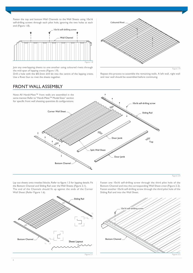
Repeat this process to assemble the remaining walls. A left wall, right wall and rear wall should be assembled before continuing.
Bottom Channel
10x16 self-drilling screw
Figure 2.1
Lay out sheets onto trestles / blocks. Refer to figure 1.5 for lapping details. Fit the Bottom Channel and Sliding Rail over the Wall Sheets (Figure 2.1).The end of the Channels should fit up against the ends of the Corner Wall Sheet (Refer Figure 1.6).
FRONT WALL ASSEMBLY
Figure 2.0
Note: All Handi-Mate™ front walls are assembled in the same manner. Refer to “Handi-Mate™ Model Sizes” section for specific front wall sheeting quantities & configurations.
Sliding Rail
Bottom Channel
Door Jamb
10x16 self-drilling screw
Door Jamb
Corner Wall Sheet
Split Wall Sheet
Top
Sliding Rail
Bottom Channel
Fasten one 10x16 self-drilling screw through the third pilot hole of the Bottom Channel and into the corresponding Wall Sheet crest (Figure 2.2).Fasten another 10x16 self-drilling screw through the third pilot hole of the Sliding Rail and into the Wall Sheet.
Figure 2.2
Sheet Layout
Join any overlapping sheets to one another using coloured rivets through the mid-span of lapping crests (Figure 1.9).Drill a hole with the ø3.5mm drill bit into the centre of the lapping crests. Use a Rivet Gun to rivet the sheets together.
7
Fit the Door Jamb over the Wall Sheet, ensuring it is inside the Bottom Channel and Sliding Rail (Figure 2.3).
Fasten one 10x16 self-drilling screw through the underside of the Bottom Channel & Sliding Rail and into the Door Jamb (Figure 2.5).
Figure 2.3
Figure 2.6
Door Jamb
Sliding Rail
Bottom Channel
Sliding Rail
Bottom Channel
10x16 self-drilling screw
Figure 2.5
Door Jamb
Approx.150mm
Coloured Rivet
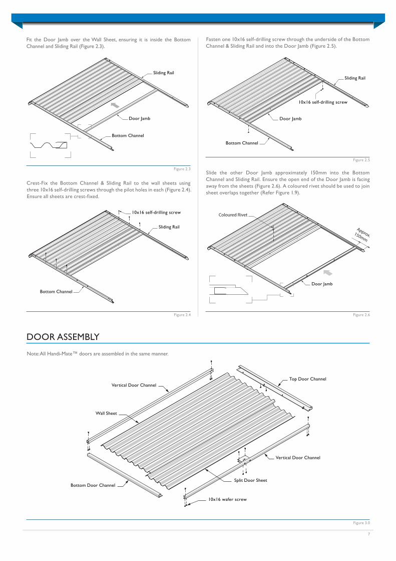
DOOR ASSEMBLY
Figure 3.0
Bottom Door Channel
Vertical Door Channel
Top Door ChannelVertical Door Channel
Wall Sheet
Split Door Sheet
10x16 wafer screw
Note: All Handi-Mate™ doors are assembled in the same manner.
Figure 2.4
Sliding Rail
Bottom Channel
10x16 self-drilling screw
Door Jamb
Slide the other Door Jamb approximately 150mm into the Bottom Channel and Sliding Rail. Ensure the open end of the Door Jamb is facing away from the sheets (Figure 2.6). A coloured rivet should be used to join sheet overlaps together (Refer Figure 1.9).
Crest-Fix the Bottom Channel & Sliding Rail to the wall sheets using three 10x16 self-drilling screws through the pilot holes in each (Figure 2.4). Ensure all sheets are crest-fixed.
8
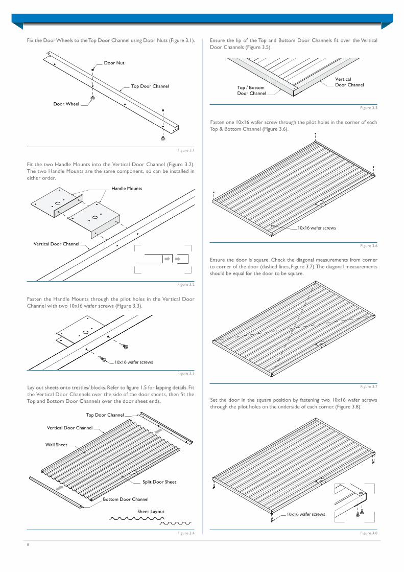
Ensure the door is square. Check the diagonal measurements from corner to corner of the door (dashed lines, Figure 3.7). The diagonal measurements should be equal for the door to be square.
Ensure the lip of the Top and Bottom Door Channels fit over the Vertical Door Channels (Figure 3.5).
Fasten the Handle Mounts through the pilot holes in the Vertical Door Channel with two 10x16 wafer screws (Figure 3.3).
Handle Mounts
Vertical Door Channel
Figure 3.2
Fit the two Handle Mounts into the Vertical Door Channel (Figure 3.2). The two Handle Mounts are the same component, so can be installed in either order.
Door Nut
Top Door Channel
Door Wheel
Figure 3.1
Fix the Door Wheels to the Top Door Channel using Door Nuts (Figure 3.1).
10x16 wafer screws
Figure 3.3
Vertical Door Channel
Bottom Door Channel
Top Door Channel
Sheet Layout
Wall Sheet
Split Door Sheet
Figure 3.4
10x16 wafer screws
Figure 3.6
Figure 3.5
Top / BottomDoor Channel
VerticalDoor Channel
Figure 3.7
10x16 wafer screws
Figure 3.8
Lay out sheets onto trestles/ blocks. Refer to figure 1.5 for lapping details. Fit the Vertical Door Channels over the side of the door sheets, then fit the Top and Bottom Door Channels over the door sheet ends. Set the door in the square position by fastening two 10x16 wafer screws
through the pilot holes on the underside of each corner. (Figure 3.8).
Fasten one 10x16 wafer screw through the pilot holes in the corner of each Top & Bottom Channel (Figure 3.6).
9
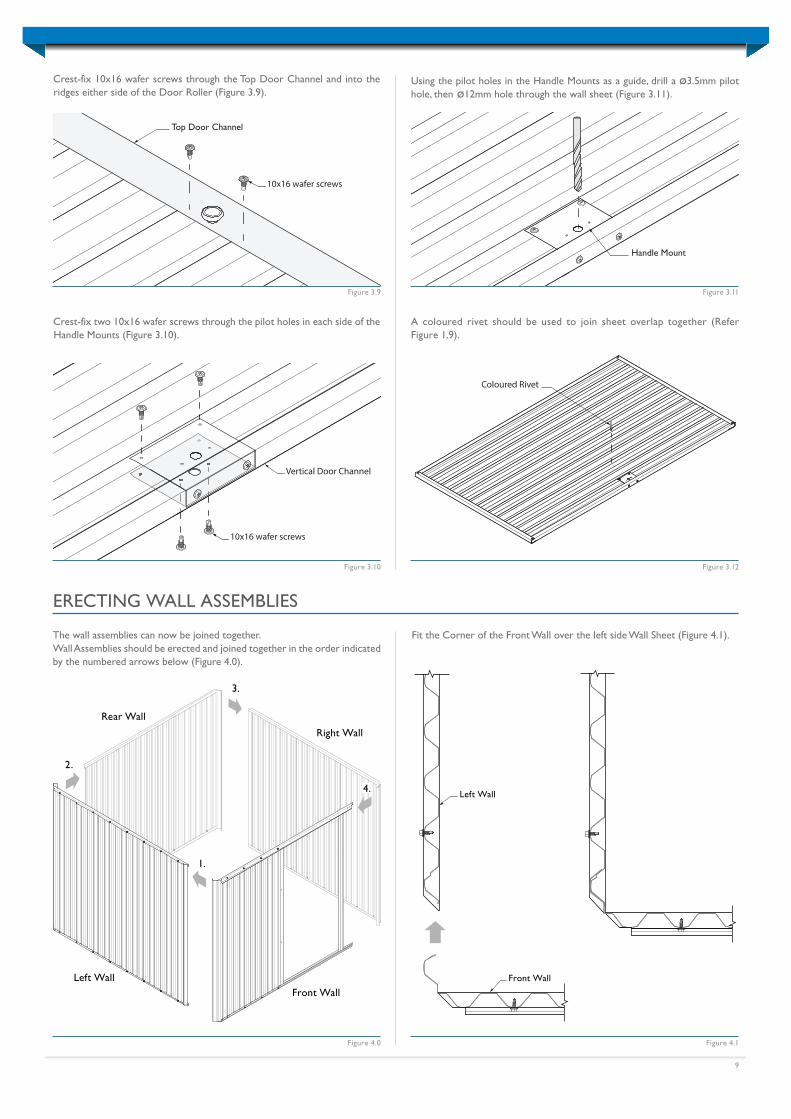
Crest-fix 10x16 wafer screws through the Top Door Channel and into the ridges either side of the Door Roller (Figure 3.9).
Handle Mount
Using the pilot holes in the Handle Mounts as a guide, drill a ø3.5mm pilot hole, then ø12mm hole through the wall sheet (Figure 3.11).
Figure 3.11
Coloured Rivet
A coloured rivet should be used to join sheet overlap together (Refer Figure 1.9).
Figure 3.12
Top Door Channel
10x16 wafer screws
Figure 3.9
Vertical Door Channel
10x16 wafer screws
Figure 3.10
Crest-fix two 10x16 wafer screws through the pilot holes in each side of the Handle Mounts (Figure 3.10).
ERECTING WALL ASSEMBLIES
The wall assemblies can now be joined together.Wall Assemblies should be erected and joined together in the order indicated by the numbered arrows below (Figure 4.0).
Left Wall
Front Wall
Fit the Corner of the Front Wall over the left side Wall Sheet (Figure 4.1).
Figure 4.0 Figure 4.1
1.
2.
3.
Front WallLeft Wall
Right Wall
Rear Wall
4.
10
Corner Bracket
Top Channel
Figure 4.2
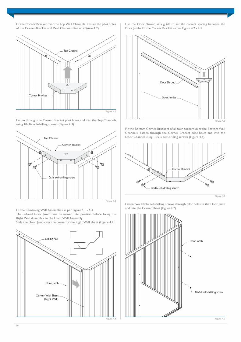
Fit the Corner Bracket over the Top Wall Channels. Ensure the pilot holes of the Corner Bracket and Wall Channels line up (Figure 4.2).
10x16 self-drilling screw
Corner Bracket
Top Channel
Figure 4.3
Fasten through the Corner Bracket pilot holes and into the Top Channels using 10x16 self-drilling screws (Figure 4.3).
10x16 self-drilling screw
Corner Bracket
Figure 4.6
Fit the Bottom Corner Brackets of all four corners over the Bottom Wall Channels. Fasten through the Corner Bracket pilot holes and into the Door Channel using 10x16 self-drilling screws (Figure 4.6).
Door Shroud
Door Jambs
Figure 4.5
Use the Door Shroud as a guide to set the correct spacing between the Door Jambs. Fit the Corner Bracket as per Figure 4.2 - 4.3.
Door Jamb
Sliding Rail
Corner Wall Sheet(Right Wall)
Fit the Remaining Wall Assemblies as per Figure 4.1 - 4.3.The unfixed Door Jamb must be moved into position before fixing the Right Wall Assembly to the Front Wall Assembly.Slide the Door Jamb over the corner of the Right Wall Sheet (Figure 4.4).
Figure 4.4
Door Jamb
10x16 self-drilling screw
Figure 4.7
Fasten two 10x16 self-drilling screws through pilot holes in the Door Jamb and into the Corner Sheet (Figure 4.7).
11
Barge Support
Front Wall
Sliding Rail
10x16 self-drilling screw
Figure 4.8
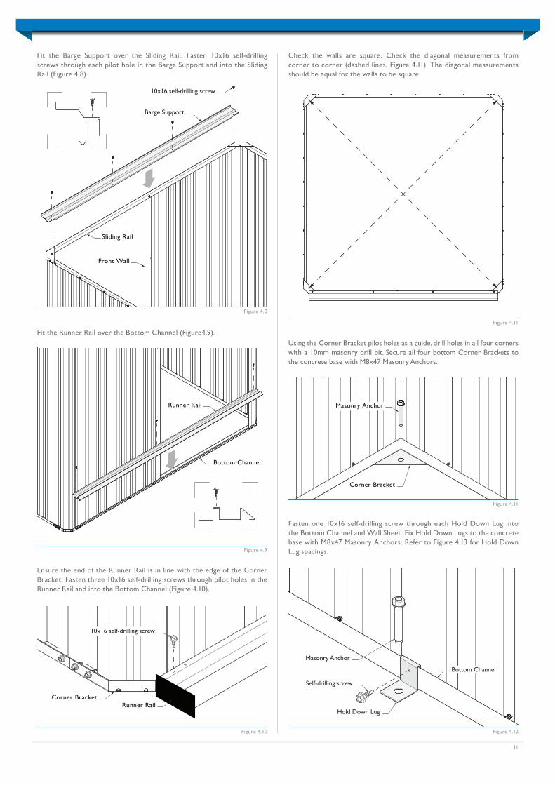
Fit the Barge Support over the Sliding Rail. Fasten 10x16 self-drilling screws through each pilot hole in the Barge Support and into the Sliding Rail (Figure 4.8).
Runner Rail
Bottom Channel
Figure 4.9
Fit the Runner Rail over the Bottom Channel (Figure4.9).
Figure 4.10
Ensure the end of the Runner Rail is in line with the edge of the Corner Bracket. Fasten three 10x16 self-drilling screws through pilot holes in the Runner Rail and into the Bottom Channel (Figure 4.10).
Runner RailCorner Bracket
10x16 self-drilling screw
Figure 4.11
Check the walls are square. Check the diagonal measurements from corner to corner (dashed lines, Figure 4.11). The diagonal measurements should be equal for the walls to be square.
Masonry Anchor
Corner Bracket
Figure 4.11
Using the Corner Bracket pilot holes as a guide, drill holes in all four corners with a 10mm masonry drill bit. Secure all four bottom Corner Brackets to the concrete base with M8x47 Masonry Anchors.
Figure 4.12
Fasten one 10x16 self-drilling screw through each Hold Down Lug into the Bottom Channel and Wall Sheet. Fix Hold Down Lugs to the concrete base with M8x47 Masonry Anchors. Refer to Figure 4.13 for Hold Down Lug spacings.
Hold Down Lug
Masonry Anchor
Self-drilling screw
Bottom Channel
Anchor Spacing
12
Ridge Cap
Ridge Beam
Roof Sheet
R/H Barge Cap
L/H Barge Cap
Ridge Beam
Barge Support
Half shed width
Wall Channel
Figure 5.1
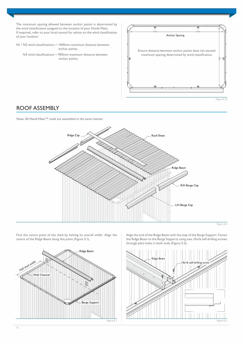
Find the centre point of the shed by halving its overall width. Align the centre of the Ridge Beam along this point (Figure 5.1).
Figure 5.2
ROOF ASSEMBLY
Figure 5.0
10x16 self-drilling screwRidge Beam
Align the end of the Ridge Beam with the step of the Barge Support. Fasten the Ridge Beam to the Barge Supports using two 10x16 self-drilling screws through pilot holes in both ends (Figure 5.2).
Hold Down Lug
Masonry Anchor
Self-drilling screw
Bottom Channel
Anchor Spacing
Figure 4.13
The maximum spacing allowed between anchor points is determined by the wind classification assigned to the location of your Handi-Mate.If required, refer to your local council for advice on the wind classification of your location.
N1 / N2 wind classifications = 1400mm maximum distance between anchor points.
N3 wind classifications = 900mm maximum distance between anchor points.
Note: All Handi-Mate™ roofs are assembled in the same manner.
Ensure distance between anchor points does not exceed maximum spacing determined by wind classification.
13
Front Wall
Rear Wall
Wall Channel
Roof Sheet
Ridge Beam
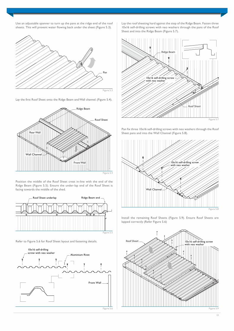
Ridge Beam endRoof Sheet underlap
10x16 self-drilling screwwith neo washer
Roof Sheet
Ridge Beam
Figure 5.4
Figure 5.5
Position the middle of the Roof Sheet crest in-line with the end of the Ridge Beam (Figure 5.5). Ensure the under-lap end of the Roof Sheet is facing towards the middle of the shed.
Figure 5.7
Lay the roof sheeting hard against the step of the Ridge Beam. Fasten three 10x16 self-drilling screws with neo washers through the pans of the Roof Sheet and into the Ridge Beam (Figure 5.7).
Lay the first Roof Sheet onto the Ridge Beam and Wall channel. (Figure 5.4).
Pan
Figure 5.3
Use an adjustable spanner to turn up the pans at the ridge end of the roof sheets. This will prevent water flowing back under the sheet (Figure 5.3).
Wall Channel
10x16 self-drilling screwwith neo washer
Figure 5.8
Pan fix three 10x16 self-drilling screws with neo washers through the Roof Sheet pans and into the Wall Channel (Figure 5.8).
10x16 self-drilling screwwith neo washer
Roof Sheet
Figure 5.9
Install the remaining Roof Sheets (Figure 5.9). Ensure Roof Sheets are lapped correctly (Refer Figure 5.6)
Aluminium Rivet
10x16 self-drillingscrew with neo washer
Front Wall
Figure 5.6
Refer to Figure 5.6 for Roof Sheet layout and fastening details.
14
Figure 5.12
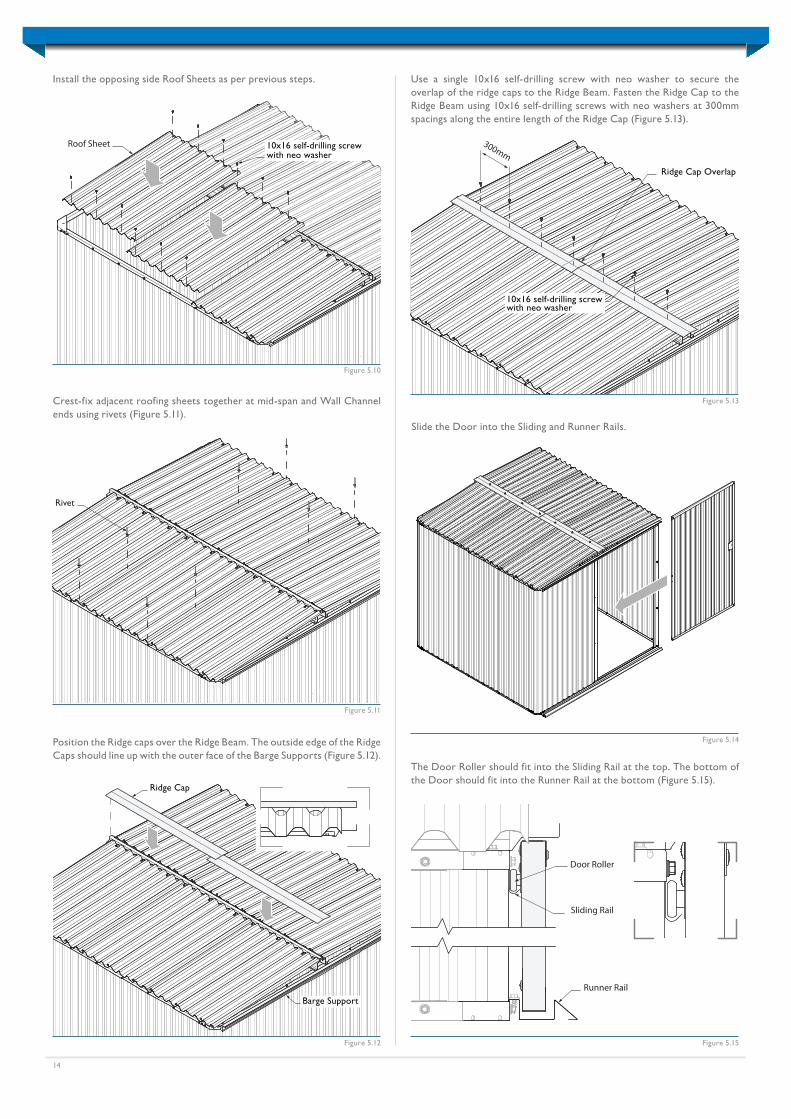
Position the Ridge caps over the Ridge Beam. The outside edge of the Ridge Caps should line up with the outer face of the Barge Supports (Figure 5.12).
Ridge Cap
Barge Support
300mm
Ridge Cap Overlap
10x16 self-drilling screwwith neo washer
Figure 5.13
Use a single 10x16 self-drilling screw with neo washer to secure the overlap of the ridge caps to the Ridge Beam. Fasten the Ridge Cap to the Ridge Beam using 10x16 self-drilling screws with neo washers at 300mm spacings along the entire length of the Ridge Cap (Figure 5.13).
Sliding Rail
Runner Rail
Door Roller
Figure 5.15
The Door Roller should fit into the Sliding Rail at the top. The bottom of the Door should fit into the Runner Rail at the bottom (Figure 5.15).
Figure 5.14
Slide the Door into the Sliding and Runner Rails.
10x16 self-drilling screwwith neo washer
Roof Sheet
Figure 5.10
Install the opposing side Roof Sheets as per previous steps.
Rivet
Figure 5.11
Crest-fix adjacent roofing sheets together at mid-span and Wall Channel ends using rivets (Figure 5.11).
15
R/H Barge Cap
L/H Barge Cap
Barge Support
Figure 5.21
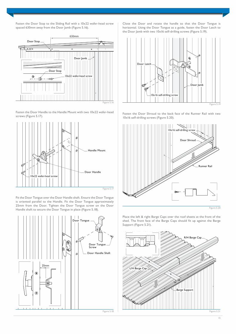
Place the left & right Barge Caps over the roof sheets at the front of the shed. The front face of the Barge Caps should fit up against the Barge Support (Figure 5.21).
630mm
Door Jamb
Door Stop
Door Stop
10x22 wafer-head screw
Figure 5.16
Fasten the Door Stop to the Sliding Rail with a 10x22 wafer-head screw spaced 630mm away from the Door Jamb (Figure 5.16).
Figure 5.17
Fasten the Door Handle to the Handle Mount with two 10x22 wafer-head screws (Figure 5.17).
25mm
Door Tongue
Door TongueScrew
Door Handle Shaft
Door Handle
Handle Mount
10x22 wafer-head screw
Figure 5.18
Fit the Door Tongue over the Door Handle shaft. Ensure the Door Tongue is oriented parallel to the Handle. Fit the Door Tongue approximately 25mm from the Door. Tighten the Door Tongue screw on the Door Handle shaft to secure the Door Tongue in place (Figure 5.18).
Door Latch
Door Jamb
10x16 self-drilling screw
Figure 5.19
Close the Door and rotate the handle so that the Door Tongue is horizontal. Using the Door Tongue as a guide, fasten the Door Latch to the Door Jamb with two 10x16 self-drilling screws (Figure 5.19).
Door Shroud
Runner Rail
10x16 self-drilling screw
Figure 5.20
Fasten the Door Shroud to the back face of the Runner Rail with two 10x16 self-drilling screws (Figure 5.20).
16
L/H Barge Cap
R/H Barge Cap
Coloured 10x25 self-drillingscrew with neo washer
220mm
Figure 5.22
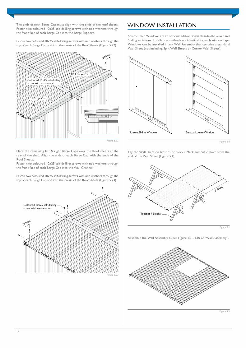
The ends of each Barge Cap must align with the ends of the roof sheets. Fasten two coloured 10x25 self-drilling screws with neo washers through the front face of each Barge Cap into the Barge Support.
Fasten two coloured 10x25 self-drilling screws with neo washers through the top of each Barge Cap and into the crests of the Roof Sheets (Figure 5.22).
220mm
Coloured 10x25 self-drillingscrew with neo washer
Figure 5.23
Place the remaining left & right Barge Caps over the Roof sheets at the rear of the shed. Align the ends of each Barge Cap with the ends of the Roof Sheets.Fasten two coloured 10x25 self-drilling screws with neo washers through the front face of each Barge Cap into the Wall Channel.
Fasten two coloured 10x25 self-drilling screws with neo washers through the top of each Barge Cap and into the crests of the Roof Sheets (Figure 5.23).
Trestles / Blocks
750mm
Lay the Wall Sheet on trestles or blocks. Mark and cut 750mm from the end of the Wall Sheet (Figure 5.1).
Figure 5.1
Assemble the Wall Assembly as per Figure 1.3 - 1.10 of “Wall Assembly”.
Figure 5.2
Stratco Shed Windows are an optional add-on, avaliable in both Louvre and Sliding variations. Installation methods are identical for each window type. Windows can be installed in any Wall Assembly that contains a standard Wall Sheet (not including Split Wall Sheets or Corner Wall Sheets).
WINDOW INSTALLATION
Stratco Louvre WindowStratco Sliding Window
Figure 5.0
17
Figure 5.3
Wall Channel
Wall Channel
Window
Figure 5.4
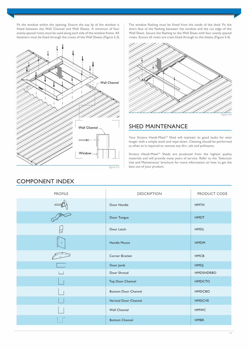
The window flashing must be fitted from the inside of the shed. Fit the short face of the flashing between the window and the cut edge of the Wall Sheet. Secure the flashing to the Wall Sheet with four evenly spaced rivets. Ensure all rivets are crest-fixed through to the sheets (Figure 5.4).
Fit the window within the opening. Ensure the top lip of the window is fitted between the Wall Channel and Wall Sheets. A minimum of four evenly spaced rivets must be used along each side of the window frame. All fasteners must be fixed through the crests of the Wall Sheets (Figure 5.3).
SHED MAINTENANCE
Your Stratco Handi-MateTM Shed will maintain its good looks for even longer with a simple wash and wipe down. Cleaning should be performed as often as is required to remove any dirt, salt and pollutants.
Stratco Handi-MateTM Sheds are produced from the highest quality materials and will provide many years of service. Refer to the ‘Selection Use and Maintenance’ brochure for more information on how to get the best out of your product.
PROFILE DESCRIPTION PRODUCT CODE
Door Handle HMTH
Door Tongue HMDT
Door Latch HMDL
Handle Mount HMDM
Corner Bracket HMCB
Door Jamb HMDJ
Door Shroud HMDSHDRBO
Top Door Channel HMDCTO
Bottom Door Channel HMDCBO
Vertical Door Channel HMDCVE
Wall Channel HMWC
Bottom Channel HMBR
COMPONENT INDEX
« Scan this QR code with your smart phone to find a Stratco near you.
QUEENSLAND • NEW SOUTH WALES • VICTORIAAUSTRALIAN CAPITAL TERRITORY • SOUTH AUSTRALIAWESTERN AUSTRALIA • NORTHERN TERRITORY stratco.com.au
Ph: 1300 155 155All brands and logos/images accompanied by ® or ™ are trade marks of Stratco (Australia) Pty Limited.
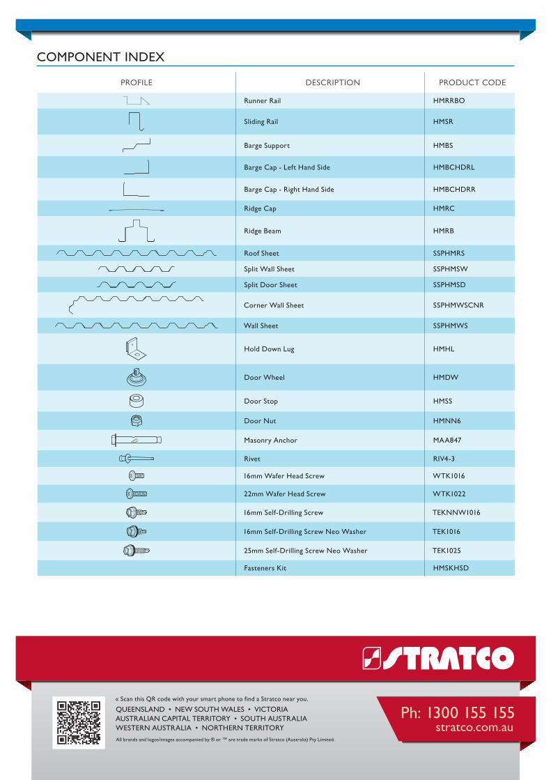
PROFILE DESCRIPTION PRODUCT CODE
Runner Rail HMRRBO
Sliding Rail HMSR
Barge Support HMBS
Barge Cap - Left Hand Side HMBCHDRL
Barge Cap - Right Hand Side HMBCHDRR
Ridge Cap HMRC
Ridge Beam HMRB
Roof Sheet SSPHMRS
Split Wall Sheet SSPHMSW
Split Door Sheet SSPHMSD
Corner Wall Sheet SSPHMWSCNR
Wall Sheet SSPHMWS
Hold Down Lug HMHL
Door Wheel HMDW
Door Stop HMSS
Door Nut HMNN6
Masonry Anchor MAA847
Rivet RIV4-3
16mm Wafer Head Screw WTK1016
22mm Wafer Head Screw WTK1022
16mm Self-Drilling Screw TEKNNW1016
16mm Self-Drilling Screw Neo Washer TEK1016
25mm Self-Drilling Screw Neo Washer TEK1025
Fasteners Kit HMSKHSD
COMPONENT INDEX