Handheld Spectrum Analyzers
16
Boosting wireless efficiency Data Sheet 9102 and 9103 Handheld Spectrum Analyzers
Transcript of Handheld Spectrum Analyzers
Boosting wireless effi ciency
Da
ta S
he
et
9102 and 9103
Handheld Spectrum
Analyzers
2
Willtek 9102 and 9103 Handheld Spectrum Analyzers
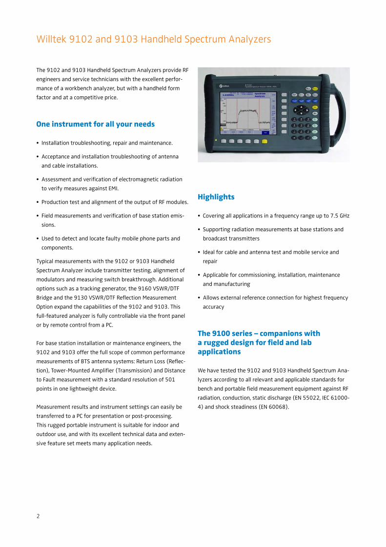
The 9102 and 9103 Handheld Spectrum Analyzers provide RF
engineers and service technicians with the excellent perfor-
mance of a workbench analyzer, but with a handheld form
factor and at a competitive price.
One instrument for all your needs
Installation troubleshooting, repair and maintenance.•
Acceptance and installation troubleshooting of antenna •
and cable installations.
Assessment and verifi cation of electromagnetic radiation •
to verify measures against EMI.
Production test and alignment of the output of RF modules.•
Field measurements and verifi cation of base station emis-•
sions.
Used to detect and locate faulty mobile phone parts and •
components.
Typical measurements with the 9102 or 9103 Handheld
Spectrum Analyzer include transmitter testing, alignment of
modulators and measuring switch breakthrough. Additional
options such as a tracking generator, the 9160 VSWR/DTF
Bridge and the 9130 VSWR/DTF Refl ection Measurement
Option expand the capabilities of the 9102 and 9103. This
full-featured analyzer is fully controllable via the front panel
or by remote control from a PC.
For base station installation or maintenance engineers, the
9102 and 9103 offer the full scope of common performance
measurements of BTS antenna systems: Return Loss (Refl ec-
tion), Tower-Mounted Amplifi er (Transmission) and Distance
to Fault measurement with a standard resolution of 501
points in one lightweight device.
Measurement results and instrument settings can easily be
transferred to a PC for presentation or post-processing.
This rugged portable instrument is suitable for indoor and
outdoor use, and with its excellent technical data and exten-
sive feature set meets many application needs.
Highlights
Covering all applications in a frequency range up to 7.5 GHz•
Supporting radiation measurements at base stations and •
broadcast transmitters
Ideal for cable and antenna test and mobile service and •
repair
Applicable for commissioning, installation, maintenance •
and manufacturing
Allows external reference connection for highest frequency •
accuracy
The 9100 series – companions with a rugged design for fi eld and lab applications
We have tested the 9102 and 9103 Handheld Spectrum Ana-
lyzers according to all relevant and applicable standards for
bench and portable fi eld measurement equipment against RF
radiation, conduction, static discharge (EN 55022, IEC 61000-
4) and shock steadiness (EN 60068).
3
Wide frequency band covers 3G, Wireless LAN and GPS
Comprehensive feature set in single-button measurement
With its clear and easy operation, the 9102 and 9103 Hand-
held Spectrum Analyzers present all measurement functions
required to quickly and precisely resolve measurement tasks.
The user-friendly interface with intuitive softkeys enhances
operational effi ciency.
Frequencies are increasing … needn’t break the budget
The wide frequency range from 100 kHz to 4 GHz (standard
delivery) enables testing of RF systems and modules such as
modern wireless local oscillators.
This frequency coverage also captures the higher harmonics
from amplifi er or oscillator modules, plus any spurious signals
that can mix and break through into the pass-band. With the
complete coverage of carrier, IF stages and audio frequencies,
the 9102 and 9103 provide the performance needed.
The frequency range of the 9103 Spectrum Analyzer also
covers the frequency range between 5 and 6 GHz. This band
serves new broadband wireless access technologies such
as WiMAX and Wireless LAN; commercial and military radio
services in the C band are located here as well. The 7.5 GHz
frequency range is also available in the 9102 equipped with
the optional 9151 Frequency Extension 7.5 GHz.
Manual or automatic control made simple
Controlling the 9102 or 9103 with a PC is easy and con-
venient via built-in RS-232 interface or Ethernet port. All
functions of the spectrum analyzer can be controlled via the
industrial standard remote control SCPI command set.
Convenience
No time is wasted in setting up the instrument or hand-copy-
ing settings from one instrument to the other. The 9100 Data
Exchange Software, which comes with the 9100 series instru-
ments, supports enhanced manage and transfer functions.
Channel systems, limit templates, settings and correction
tables can be easily set up and maintained on a PC. Building
new limit templates and correcting tables is child’s play, using
the PC’s mouse.
A live trace can be continuously downloaded from the instru-
ment using optional software. An easy export to standard
gra-phic formats such as BMP and JPG supports the need for
quick documentation of measurement data. Likewise, stored
traces can be uploaded to set the unit to the previous mea-
surement settings.
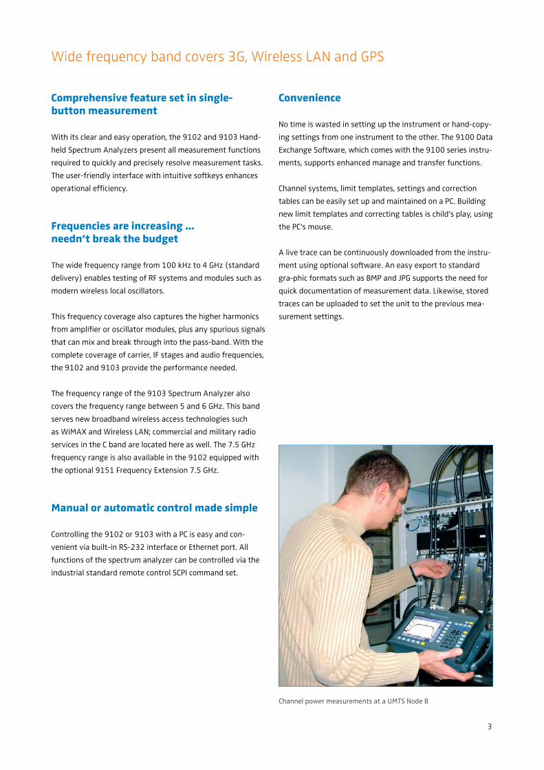
Channel power measurements at a UMTS Node B
4
Easy-to-read screen facilitates signal tracing
The high-resolution colour VGA display (640 x 480 pixels) is
excellent for fi nding misleading spurs or aligning modulators.
Multiple colours facilitate the comparison of measurement
traces on the screen. The extra bright 6.5” TFT display has a
superb 140° viewing angle and thanks to its high luminous
intensity, is ideally suited for outdoor applications. 501 mea-
suring points in a trace allow the comprehensive evaluation
of a complex frequency spectrum at a glance.
Markers assist in precise reading of signals
Six markers allow for exact reading of complex signals. The
transmitter performance can be checked, spurious signals can
be detected and sideband levels can be established, using the
markers with their fl exibility and clear on-screen display. By
pressing Delta Marker, second and third harmonic levels can
easily be checked. Power level and frequency are displayed in
relation to a reference point.
Pass/fail verdict with limit templates
Limit templates simplify assessment of complex displayed
signals and allow users to decide whether the signal passes
or fails. These templates can contain up to 30 segments.
Simultaneously, it can be established if the signal exceeds an
upper and/or lower limit or not.
High-precision frequency measurement
The integrated frequency counter expands the range of appli-
cations to high-precision frequency measurements, required
for many tasks, such as mobile phone repair. These can now
be performed with the 9102 and 9103. For high-precision
frequency measurements, users no longer need to utilize ex-
pensive spectrum analyzers or additional frequency counters.
The precision can be increased even further by connecting an
external frequency reference.
Meets future requirements
With the Multi Port, the 9102 and the 9103 are designed
to meet future requirements. The analyzers automatically
detect external options designed for this highly fl exible
spectrum analyzer, provide access to special measurement
functions and apply the corresponding correction values.
Get more out of digitally modulated signals through channel power measurement functions
The 9102 and 9103 offer Channel Power, Adjacent Channel
Power Ratio (ACPR) and Occupied Bandwidth (OBW) mea-
surement capabilities.
ACPR enables measurements of the leakage power from a
modulated communication channel into an adjacent channel.
The occupied bandwidth measurement represents the part of
the transmitted power that lies in a specifi ed bandwidth.
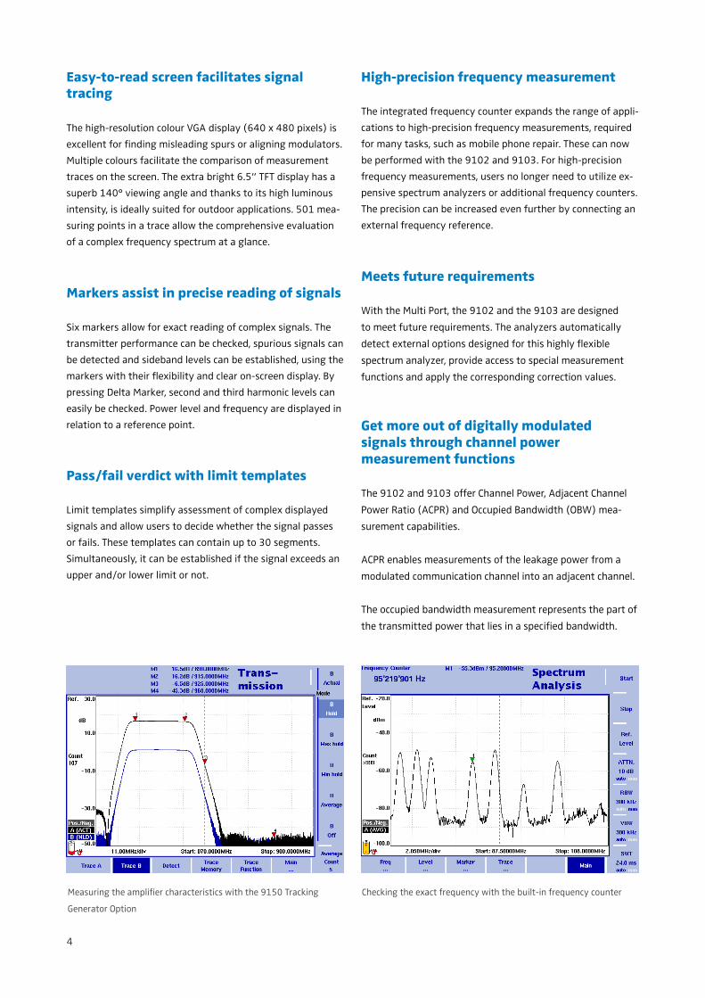
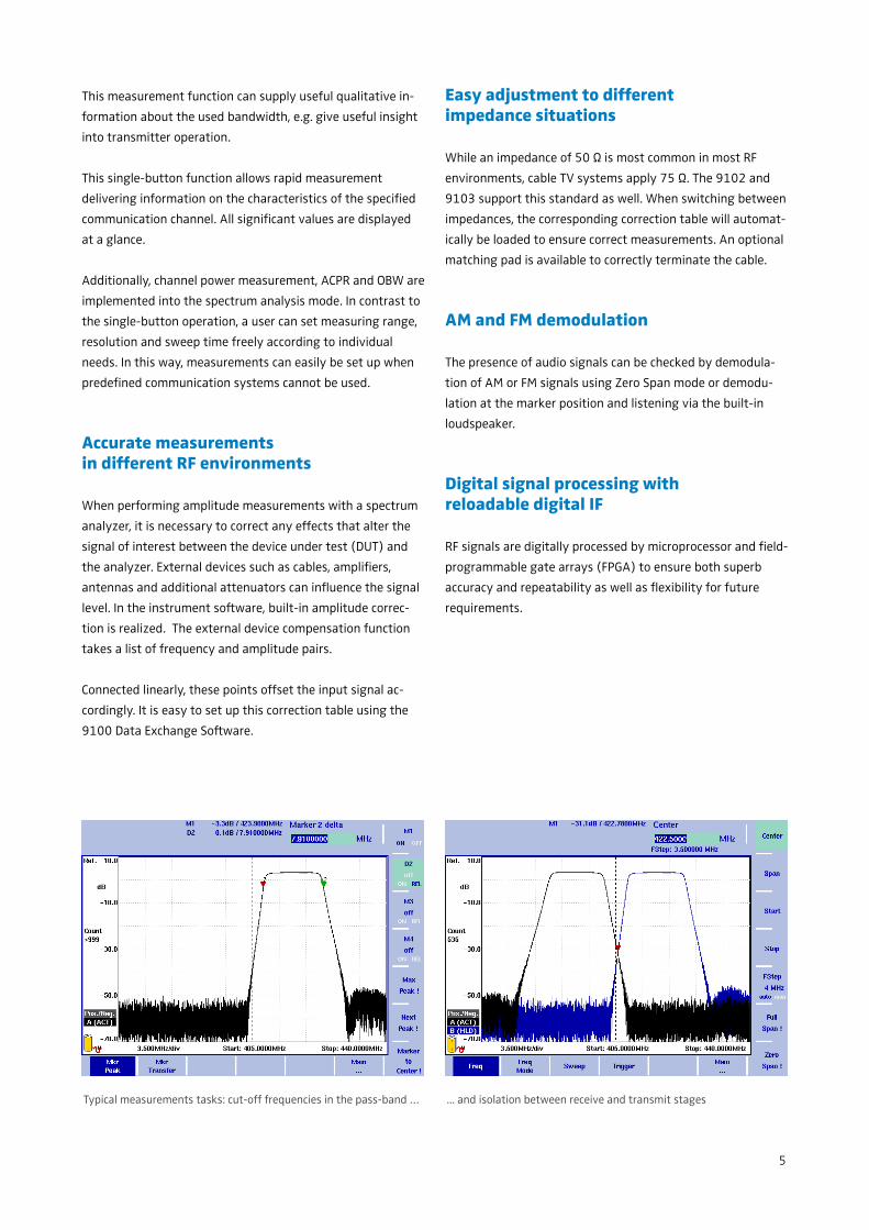
Checking the exact frequency with the built-in frequency counterMeasuring the amplifi er characteristics with the 9150 Tracking
Generator Option
5
This measurement function can supply useful qualitative in-
formation about the used bandwidth, e.g. give useful insight
into transmitter operation.
This single-button function allows rapid measurement
delivering information on the characteristics of the specifi ed
communication channel. All signifi cant values are displayed
at a glance.
Additionally, channel power measurement, ACPR and OBW are
implemented into the spectrum analysis mode. In contrast to
the single-button operation, a user can set measuring range,
resolution and sweep time freely according to individual
needs. In this way, measurements can easily be set up when
predefi ned communication systems cannot be used.
Accurate measurementsin different RF environments
When performing amplitude measurements with a spectrum
analyzer, it is necessary to correct any effects that alter the
signal of interest between the device under test (DUT) and
the analyzer. External devices such as cables, amplifi ers,
antennas and additional attenuators can infl uence the signal
level. In the instrument software, built-in amplitude correc-
tion is realized. The external device compensation function
takes a list of frequency and amplitude pairs.
Connected linearly, these points offset the input signal ac-
cordingly. It is easy to set up this correction table using the
9100 Data Exchange Software.
Easy adjustment to differentimpedance situations
While an impedance of 50 Ω is most common in most RF
environments, cable TV systems apply 75 Ω. The 9102 and
9103 support this standard as well. When switching between
impedances, the corresponding correction table will automat-
ically be loaded to ensure correct measurements. An optional
matching pad is available to correctly terminate the cable.
AM and FM demodulation
The presence of audio signals can be checked by demodula-
tion of AM or FM signals using Zero Span mode or demodu-
lation at the marker position and listening via the built-in
loudspeaker.
Digital signal processing with reloadable digital IF
RF signals are digitally processed by microprocessor and fi eld-
programmable gate arrays (FPGA) to ensure both superb
accuracy and repeatability as well as fl exibility for future
requirements.
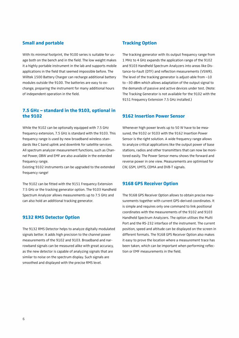
Typical measurements tasks: cut-off frequencies in the pass-band … ... and isolation between receive and transmit stages
6
Small and portable
With its minimal footprint, the 9100 series is suitable for us-
age both on the bench and in the fi eld. The low weight makes
it a highly portable instrument in the lab and supports mobile
applications in the fi eld that seemed impossible before. The
Willtek 1500 Battery Charger can recharge additional battery
modules outside the 9100. The batteries are easy to ex-
change, preparing the instrument for many additional hours
of independent operation in the fi eld.
7.5 GHz – standard in the 9103, optional in the 9102
While the 9102 can be optionally equipped with 7.5 GHz
frequency extension, 7.5 GHz is standard with the 9103. This
frequency range is used by new broadband wireless stan-
dards like C band uplink and downlink for satellite services.
All spectrum analyzer measurement functions, such as Chan-
nel Power, OBW and EMF are also available in the extended
frequency range.
Existing 9102 instruments can be upgraded to the extended
frequency range!
The 9102 can be fi tted with the 9151 Frequency Extension
7.5 GHz or the tracking generator option. The 9103 Handheld
Spectrum Analyzer allows measurements up to 7.5 GHz and
can also hold an additional tracking generator.
9132 RMS Detector Option
The 9132 RMS Detector helps to analyze digitally modulated
signals better. It adds high precision to the channel power
measurements of the 9102 and 9103. Broadband and nar-
rowband signals can be measured alike with great accuracy,
as the new detector is capable of analyzing signals that are
similar to noise on the spectrum display. Such signals are
smoothed and displayed with the precise RMS level.
Tracking Option
The tracking generator with its output frequency range from
1 MHz to 4 GHz expands the application range of the 9102
and 9103 Handheld Spectrum Analyzers into areas like Dis-
tance-to-Fault (DTF) and refl ection measurements (VSWR).
The level of the tracking generator is adjust-able from –10
to –30 dBm which allows adaptation of the output signal to
the demands of passive and active devices under test. (Note:
The Tracking Generator is not available for the 9102 with the
9151 Frequency Extension 7.5 GHz installed.)
9162 Insertion Power Sensor
Whenever high power levels up to 50 W have to be mea-
sured, the 9102 or 9103 with the 9162 Insertion Power
Sensor is the right solution. A wide frequency range allows
to analyze critical applications like the output power of base
stations, radios and other transmitters that can now be moni-
tored easily. The Power Sensor menu shows the forward and
reverse power in one view. Measurements are optimised for
CW, GSM, UMTS, CDMA and DVB-T signals.
9168 GPS Receiver Option
The 9168 GPS Receiver Option allows to obtain precise mea-
surements together with current GPS-derived coordinates. It
is simple and requires only one command to link positional
coordinates with the measurements of the 9102 and 9103
Handheld Spectrum Analyzers. The option utilises the Multi
Port and the RS-232 interface of the instrument. The current
position, speed and altitude can be displayed on the screen in
different formats. The 9168 GPS Receiver Option also makes
it easy to prove the location where a measurement trace has
been taken, which can be important when performing refl ec-
tion or EMF measurements in the fi eld.
7
9130 VSWR/DTF Refl ection Measurement Option,
9160 VSWR/DTF Bridge
The 9130 VSWR/DTF Refl ection Measurement Option, in
conjunction with the 9160 VSWR/DTF Bridge, turns the 9102
or 9103 into a full-featured refl ection test set.
Today’s complex antenna installations include tower mounted
amplifi ers, cross polarised antennas and long cable feeds.
Measuring the antenna impedance match is the state-of-the-
art method to analyze the antenna system performance.
With the 9102 or 9103 and the 9130 VSWR/DTF Refl ection
Measurement Option, measurement technicians are ready for
all the test challenges involved.
All relevant functional parameters are available on a glance
with the refl ection measurement mode. With the limit line
capability results can easily be compared with the limits
specifi ed by the network operator.
Depending on user preference, the device displays the mea-
sured value either as a return loss or in other custom units
such as standing wave ratio (VSWR), refl ection coeffi cient
(rho) or refl ected power ratio.
Vector analysis for accurate refl ection measurements
Modern antenna systems for professional applications are
characterised by a low refl ection and a good match. The high
performance is validated for fi eld acceptance and mainte-
nance using precise instruments. The 9130 VSWR/DTF Refl ec-
tion Measurement Option provides high precision because it
performs vector measurements on the refl ected wave. This
type of measurement offers advanced accuracy and highly
reliable results even at low refl ected signal levels beyond
–20 dB of return loss.
DTF measurements for cable performance testing
Antenna installations are never complete without distance-
to-fault (DTF) measurements. The 9130 VSWR/DTF Refl ection
Measurement Option provides this type of test, based on FDR
(Frequency Domain Refl ectometry) technology. This system
option supports a detailed analysis of the antenna feeder
cable with a total length of up to 1000 m (3280 ft). Worn-
out connectors, cable kinks, water ingress or other cable
related problems can be easily detected and located. The high
measurement resolution of 501 points ensures quick and
effi cient troubleshooting by detecting even small refl ections;
these result in a displayed distance to fault.
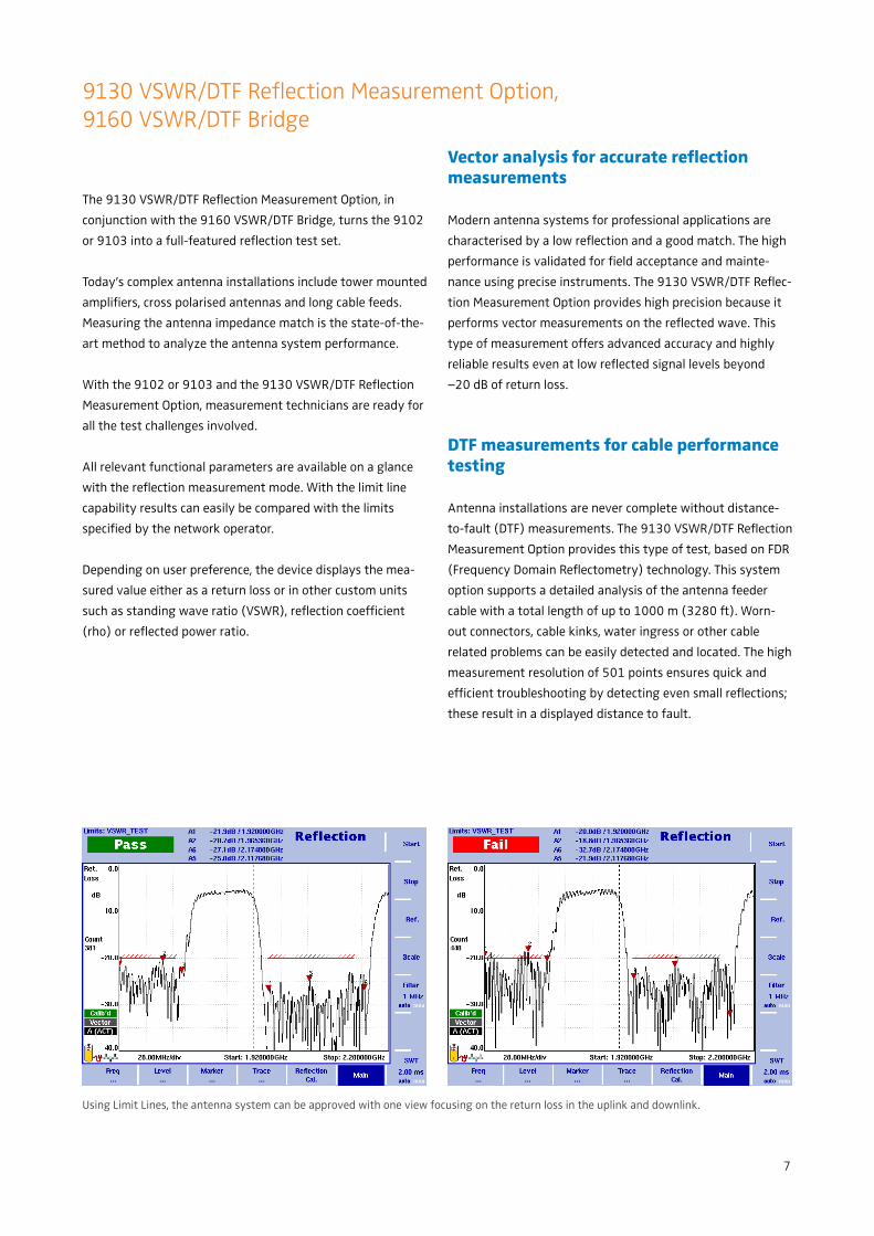
Using Limit Lines, the antenna system can be approved with one view focusing on the return loss in the uplink and downlink.
8
…and easy and time-saving documentation of the installer's work
quality in the offi ce with the Data Exchange Software.
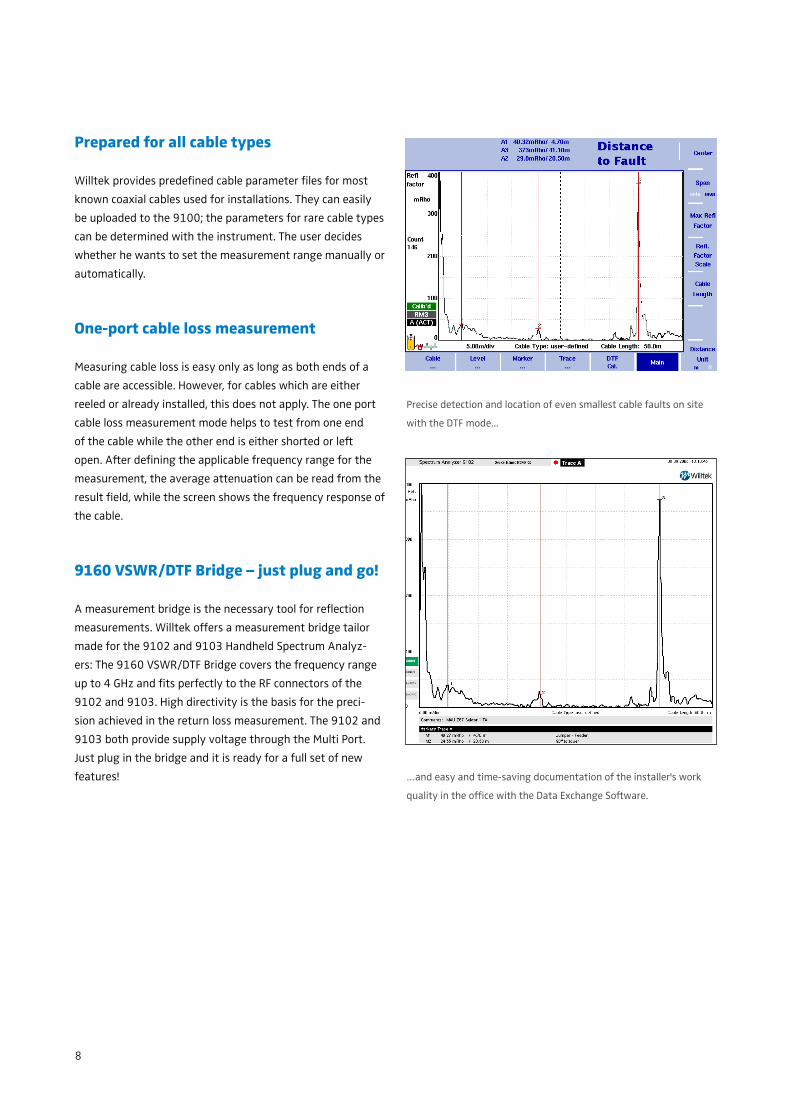
Prepared for all cable types
Willtek provides predefi ned cable parameter fi les for most
known coaxial cables used for installations. They can easily
be uploaded to the 9100; the parameters for rare cable types
can be determined with the instrument. The user decides
whether he wants to set the measurement range manually or
automatically.
One-port cable loss measurement
Measuring cable loss is easy only as long as both ends of a
cable are accessible. However, for cables which are either
reeled or already installed, this does not apply. The one port
cable loss measurement mode helps to test from one end
of the cable while the other end is either shorted or left
open. After defi ning the applicable frequency range for the
measurement, the average attenuation can be read from the
result fi eld, while the screen shows the frequency response of
the cable.
9160 VSWR/DTF Bridge – just plug and go!
A measurement bridge is the necessary tool for refl ection
measurements. Willtek offers a measurement bridge tailor
made for the 9102 and 9103 Handheld Spectrum Analyz-
ers: The 9160 VSWR/DTF Bridge covers the frequency range
up to 4 GHz and fi ts perfectly to the RF connectors of the
9102 and 9103. High directivity is the basis for the preci-
sion achieved in the return loss measurement. The 9102 and
9103 both provide supply voltage through the Multi Port.
Just plug in the bridge and it is ready for a full set of new
features!
Precise detection and location of even smallest cable faults on site
with the DTF mode...
9
Radiation Measurements with the 9131 EMF Measurement Option
Radiation from base stations and broadcast stations can be
measured easily with the 9102 or 9103 and the 9131 EMF
Measurement Option. The 9100 takes measurements of the
electromagnetic fi eld over a user-defi nable frequency range
and displays the fi eld strength (in V/m) or the power fl ux
density (in W/m²).
The option also allows selecting one of two additional fi lters
(9 and 120 kHz resolution bandwidth) which are typically
used for radiation measurements.
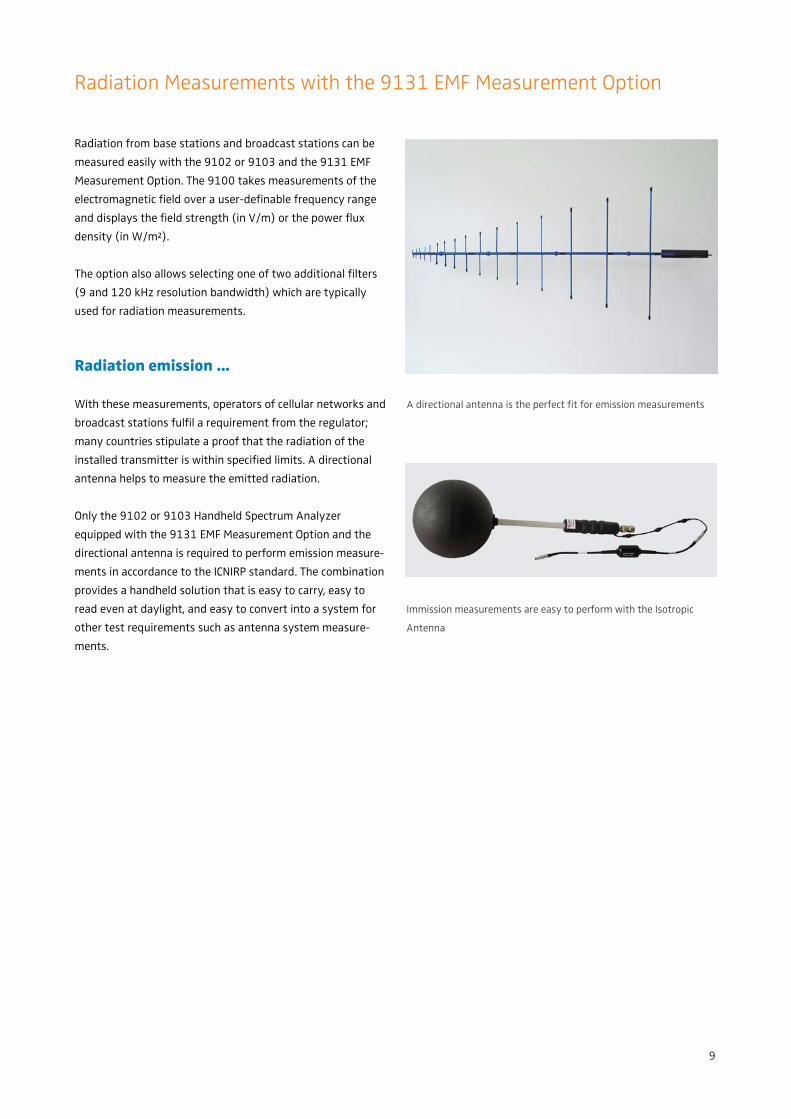
Radiation emission …
With these measurements, operators of cellular networks and
broadcast stations fulfi l a requirement from the regulator;
many countries stipulate a proof that the radiation of the
installed transmitter is within specifi ed limits. A directional
antenna helps to measure the emitted radiation.
Only the 9102 or 9103 Handheld Spectrum Analyzer
equipped with the 9131 EMF Measurement Option and the
directional antenna is required to perform emission measure-
ments in accordance to the ICNIRP standard. The combination
provides a handheld solution that is easy to carry, easy to
read even at daylight, and easy to convert into a system for
other test requirements such as antenna system measure-
ments.
A directional antenna is the perfect fi t for emission measurements
Immission measurements are easy to perform with the Isotropic
Antenna
10
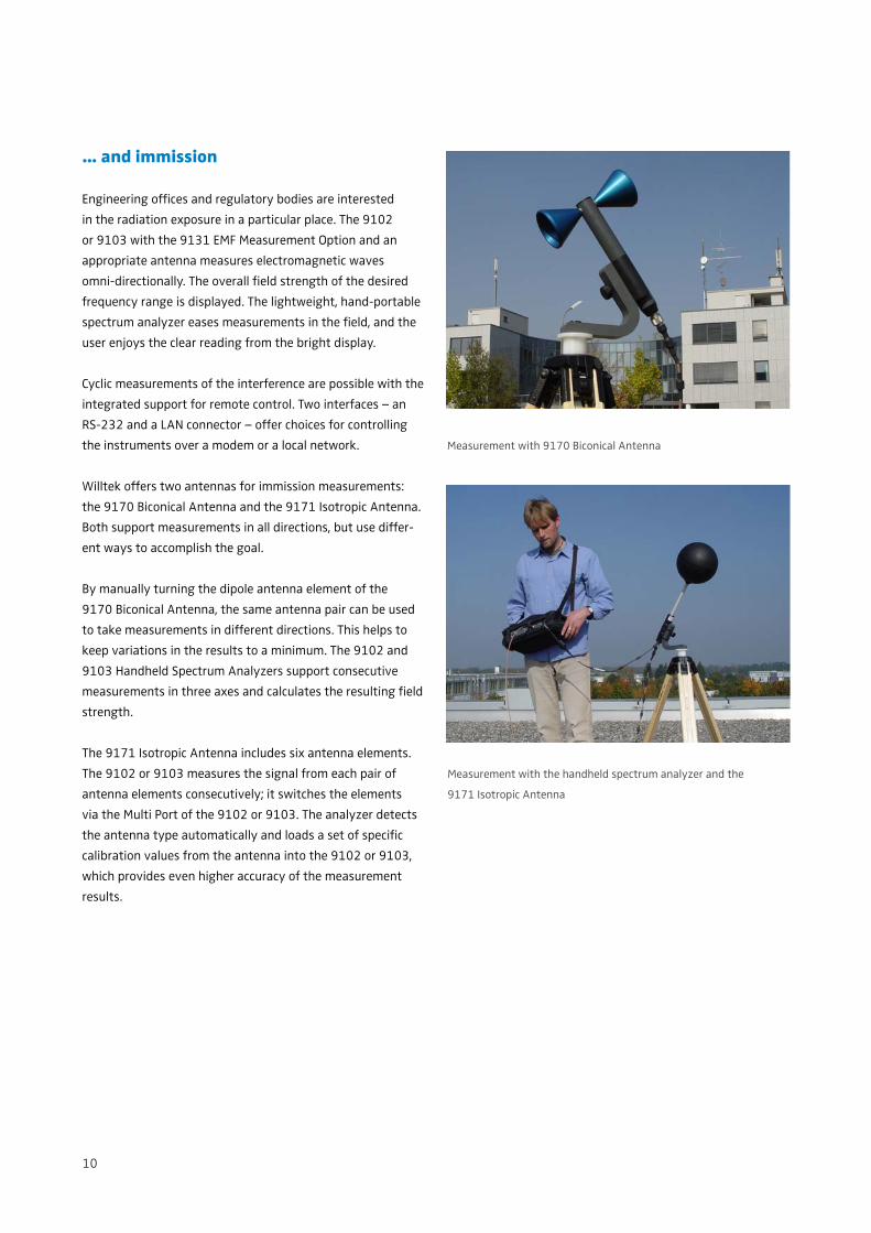
… and immission
Engineering offi ces and regulatory bodies are interested
in the radiation exposure in a particular place. The 9102
or 9103 with the 9131 EMF Measurement Option and an
appropriate antenna measures electromagnetic waves
omni-directionally. The overall fi eld strength of the desired
frequency range is displayed. The lightweight, hand-portable
spectrum analyzer eases measurements in the fi eld, and the
user enjoys the clear reading from the bright display.
Cyclic measurements of the interference are possible with the
integrated support for remote control. Two interfaces – an
RS-232 and a LAN connector – offer choices for controlling
the instruments over a modem or a local network.
Willtek offers two antennas for immission measurements:
the 9170 Biconical Antenna and the 9171 Isotropic Antenna.
Both support measurements in all directions, but use differ-
ent ways to accomplish the goal.
By manually turning the dipole antenna element of the
9170 Biconical Antenna, the same antenna pair can be used
to take measurements in different directions. This helps to
keep variations in the results to a minimum. The 9102 and
9103 Handheld Spectrum Analyzers support consecutive
measurements in three axes and calculates the resulting fi eld
strength.
The 9171 Isotropic Antenna includes six antenna elements.
The 9102 or 9103 measures the signal from each pair of
antenna elements consecutively; it switches the elements
via the Multi Port of the 9102 or 9103. The analyzer detects
the antenna type automatically and loads a set of specifi c
calibration values from the antenna into the 9102 or 9103,
which provides even higher accuracy of the measurement
results.
Measurement with 9170 Biconical Antenna
Measurement with the handheld spectrum analyzer and the
9171 Isotropic Antenna
11
Specifi cations
Specifi cations valid after 30 minutes warm-up time at ambient tem-
perature, specifi ed environmental conditions and typical measure-
ment range, within a period of one year after calibration.
Frequency
Frequency range
Measurement range
9102 (basic instrument) 100 kHz to 4 GHz
9103, 9102 with 9151 100 kHz to 7.5 GHz
Resolution 1 kHz
Reference frequency
Temperature stability ±2 ppm
Aging ±1.5 ppm
Frequency uncertainty ±1.5 ppm
Frequency counter
Resolution 1 Hz, 10 Hz, 100 Hz
Min. required input level –90 dBm
Frequency span
Setting range
9102 0 Hz, 10 kHz to 4 GHz
9103, 9102 with 9151 0 Hz, 10 kHz to 7.5 GHz
Sweep time
Span > 10 kHz 1 ms to 250 s
Span = 0 Hz 1 ms to 250 s
Resolution bandwidth (RBW)
RBW selection manual or automatic
RBW (–3 dB) range 100 Hz to 1 MHz
Steps 1, 3, 10
Video bandwidth (VBW)
VBW selection manual or automatic
VBW range (–3 dB) 10 Hz to 1 MHz
Steps 1, 3, 10
SSB noise
9102 (basic instrument)
f = 2 GHz, Δf = 100 kHz, < –80 dBc/Hz
RBW = 10 kHz, VBW = 1 kHz typ. < –83 dBc/Hz
9103, 9102 with 9151
f = 5.7 GHz, Δf = 100 kHz, < –80 dBc/Hz,
RBW = 10 kHz, VBW = 1 kHz typ. < –83 dBc/Hz
Amplitude
Maximum safe DC voltage at RF-in ±50 V
Maximum safe input power 30 dBm
Display units dBm, dBµV, dBmV, dBV, dB,
V, mV, µV, mW, µW
Measurement range
in automatic mode average noise fl oor to 20 dBm
Displayed average noise level (DANL)
(RBW = 100 Hz, attenuation = 0 dB)
9102 (basic instrument)
10 MHz to 1 GHz < –127 dBm, typ. < –130 dBm
1 GHz to 4 GHz < –130 dBm, typ. < –135 dBm
9103, 9102 with 9151
10 MHz to 5 GHz < –120 dBm, typ. < –123 dBm
5 to 7.5 GHz < –118 dBm, typ. < –120 dBm
Input attenuation
User-defi ned by direct entry or step keys. 0 dB only selectable by
direct entry to protect the fi rst mixer.
Setting range (0) 10 to 50 dB
Attenuation steps 10 dB
Dynamic range
Range > 70 dB
Max. measurable input level 20 dBm
(attenuation = 40 dB)
Min. measurable input level
9102 (basic instrument) –130 dBm
9103, 9102 with 9151, <4 GHz –119 dBm
4 GHz to 7 GHz –120 dBm
7 GHz to 7.5 GHz –112 dBm
(attenuation = 0 dB)
12
Level accuracy
(Input attenuation = 10 dB, ambient temperature from +20°C to
+26°C)
10 MHz to 3.6 GHz ±1 dB
3.6 GHz to 7.5 GHz ±1.5 dB, typ. ±1 dB
RF input match
(input attenuation = 10 dB)
VSWR
9102 (basic instrument),
10 MHz to 4 GHz < 1.6, typ. < 1.5
9103 and 9102 with 9151
100 MHz to 4 GHz < 1.6, typ. < 1.3
4 GHz to 6 GHz < 2.0, typ. < 1.6
6 GHz to 7.5 GHz < 2.3, typ. < 2.0
Reference level
Reference level setting by keyboard entry or step keys
Setting range –100 to +30 dBm
Resolution 0.1 dB
Spurious response of 9102 (basic instrument)
Image rejection (f = 1 GHz) > 80 dB
Spurious level < –90 dBm
(attenuation = 0 dB)
LO leakage < –77 dBm
(attenuation = 10 dB)
Intermodulation-free range > 63 dB
(input level –30 dBm, f1 = 990 MHz, f
2 = 992 MHz)
Spurious response of 9103 and 9102 with 9151
Image rejection (f = 6.7 GHz) > 60 dB
Spurious level (100 kHz to 3 GHz) < –86 dBm
Spurious level < –80 dBm
(3 GHz to 7.5 GHz, attenuation = 0 dB)
LO leakage (f = 7.7 GHz) < –57 dBm
(attenuation = 10 dB)
Functions
Detector & sweep
Detector types pos./neg. peak, pos. peak, neg.
peak, sample, (RMS optional)
Sweep processing actual, average, max. hold,
min. hold
Trace
Max. displayed traces 2
Trace points 2 x 5011
Trace functions A + B → A, A – B → A,
copy a>b, copy b>a
Trace A colour selectable (default is
black)
Trace B colour selectable (default is
blue)
1 Two independent traces are available (min. hold, max. hold at the same time)
Markers
Max. markers 6
Delta markers 5
Marker functions max. peak, next peak
Transfer functions M → centre frequency
M → ref. level
M → f step
Limit check
Max. no. of limit templates 99
Limit functions upper, lower, upper and lower
Max. no. of limit segments 30
Supported measurement modes
Spectrum analysis
Channel power
Signal generator (option)
Transmission (option)
Refl ection (option)
Distance to fault (option)
Cable loss (option)
EMC (option)
13
Power measurement
Max. no. of channel systems 99
Measurement functions Channel Power, ACPR, OBW
Default systems GSM, WCDMA, DECT, WLAN
Demodulation
Min. input level –50 dBm
AM/FM on marker/permanent/on multi
marker
Keyboard
Key type silicon click
Parameters shortcut keys Cent, Span, Ref
Quick setting keys Preset, Hold/Run, Clr Trc,
RCL/Store, PARAM, MODE, MKR
General
Display (TFT)
Size 6.5”
Resolution 640 x 480
Colours 256
Brightness 300 cd
Measurement result points 2 x 5011
1 Two independent traces are available (min. hold, max. hold at the same time)
Power supply
DC voltage, external 11 to 15 V / max. 28 W
Internal battery Li–Ion
Operating time, min. 2.0 h
battery fully charged, full brightness, Tracking Generator on
Memory
Type Flash disk
Capacity (setups and traces) 257
Dimensions (W x H x D)
9102 355 x 190 x 91 [mm]
14.0 x 7.5 x 3.6 [inch]
9103 355 x 190 x 104 [mm]
14.0 x 7.5 x 4.1 [inch]
Weight
With battery
9102 3.2 kg (7 lbs)
9103 3.6 kg (8 lbs)
Power supply only 0.32 kg (0.7 lbs)
Environmental conditions
(unless otherwise specifi ed) MIL-PRF28800F class 2C
Operating temperature 0 to +45°C
Storage temperature –10 to +50°C
Rel. humidity (non-condensing) 80%
Connectors
RF in
Connector type N (female)
Impedance 50 Ω
Multi Port
Connector 7-pin ODU
DC voltage 10 V, 300 mA
Short-circuit protected active
Switched control bus I2C
DC in
Connector 2.1 mm dia. barrel jack socket
Max. current 3 A
Headphone
Headphones output 3.5 mm mini jack
Loudspeaker
Serial interface
For software updates and remote control
Connector DB-9 (male)
Speed 57.6 kbit/s
Required cable null modem cable
LAN (TCP/IP)
For software updates and remote control
Connector RJ-45
Speed 10 Mbit/s
External time reference
Ref. frequency input 5 MHz, 10 MHz, 13 MHz
Ref. frequency offset < 10 ppm
Input level > 0 dBm
Connector BNC
14
Options
Tracking Generator
Output frequency range 1 MHz to 4 GHz
Output level setting range –10 to –30 dBm
adjustable in 1 dB steps
Output level uncertainty < ±2 dB
Harmonics at –10 dBm
1 MHz to 4 GHz < –20 dBc
Spurious level offset at –10 dBm
1 MHz to 10 MHz < –63 dBc
SSB – phase noise
Δf = 100 kHz < –73 dBc/Hz
Frequency stability according to reference fre-
quency
Connector type N, female
Output impedance 50 Ω
9160 VSWR/DTF Bridge
Frequency range 1 MHz to 4 GHz
Directivity 10 MHz to 3 GHz, typ. 35 dB
Insertion loss 10 MHz to 3 GHz
RF in to DUT typ. < 11 dB
RF out to DUT typ. < 9 dB
Impedance 50 Ω
Weight 410 g
Connectors N-type
Maximum input power +20 dBm
9130 VSWR/DTF Refl ection Measurement Option
Return loss measurement range 70 dB
Refl ection measurement units dB, VSWR, mRho
Refl ection measurement vector, scalar
DTF sweep setting automatic or manual
DTF resolution 501 points
DTF max. cable length 1000 m, depending on cable
attenuation
9131 EMF Measurement Option
Frequency range 100 kHz to 7.5 GHz
Measurement range 1 mV/m to 200 V/m
Measurement units dBV/m, V/m, dBm/m², W/m²
RBW (–6 dB) range 9 kHz, 120 kHz
9162 Insertion Power Sensor
Frequency range 70 MHz to 2.7 GHz
Measurement range 20 mW to 50 W
Measurement units mW, W, dBm
Directivity > 25 dB
Insertion loss < 1 dB
Signal types CW, GSM, UMTS,
CDMA, DVB-T, TETRA
Standard delivery
Power supply (90 to 240 V, 50 to 60 Hz)
Getting started manual
User’s guide on CD
9100 Data Exchange Software (1 license)
Cross-link Ethernet communication cable
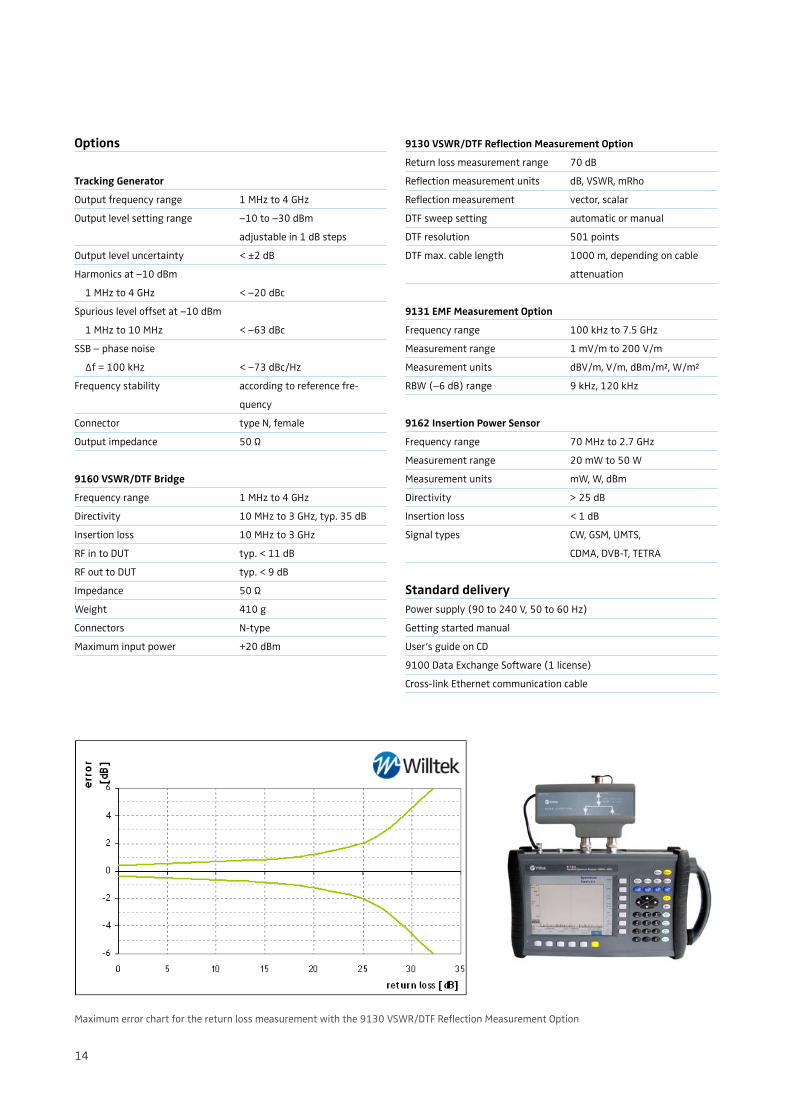
Maximum error chart for the return loss measurement with the 9130 VSWR/DTF Refl ection Measurement Option
15
Ordering information
Product packages
9102 Handheld Spectrum Analyzer M 100 412
Bench Edition
9102 Handheld Spectrum Analyzer M 248 806
Field Edition
9102 Handheld Spectrum Analyzer M 248 801
Tracking Edition
9102 Handheld Spectrum Analyzer M 248 802
VSWR/DTF Edition
9103 Handheld Spectrum Analyzer M 100 403
Bench Edition
9103 Handheld Spectrum Analyzer M 248 813
Field Edition
9103 Handheld Spectrum Analyzer M 248 814
Tracking Edition
9103 Handheld Spectrum Analyzer M 248 815
VSWR/DTF Edition
Options
9130 VSWR/DTF Refl ection M 897 261
Measurement Option
9131 EMF Measurement Option M 897 274
9132 RMS Detector Option M 897 275
9151 Frequency Extension 7.5 GHz M 248 812
(option to the 9102)
9160 VSWR/DTF Bridge M 248 966
9162 Insertion Power Sensor M 248 968
9168 GPS Receiver Option M 248 811
9102 Tracking Generator Upgrade M 248 804
9151 Frequency Extension 7.5 GHz M 248 812
Upgrade for the 9102 (re-calibration necessary)
Accessories
9100 Battery module, 7.2 Ah M 205 012
9100 Outdoor backpack M 241 015
9100 Soft carrying bag M 241 013
1500 Battery charger M 204 097
9100 Power supply M 248 328
9100 12 V car adapter M 860 389
9100 Safety lock M 867 037
9100 Data Exchange Software M 897 137
9100 Serial communication cable M 860 388
9100 Ethernet cross-link cable M 880 629
1205 RF Probe 20 dB M 248 640
Frequency range 100 kHz to 4 GHz
RF attenuation (nominal at 50 Ω) 20 dB
including adapter N (male), BNC (female)
1207 Inductive Probe M 248 971
Frequency range 4 MHz to 6 GHz
30 dB amplifi er
9170 Biconical Antenna M 860 368
9171 Isotropic Antenna M 248 809
Antenna 400 MHz band (TNC) M 860 264
Antenna 900 MHz band (TNC) M 860 261
Antenna 1800 MHz band (TNC) M 860 262
Antenna 1880 MHz band (BNC) M 860 260
Antenna 2400 MHz band (TNC) M 860 146
Triband Antenna M 860 573
2.4, 5.3, 5.8 GHz; N-type connector
Adapter N – TNC M 886 098
Adapter N – BNC M 886 097
Adapter N (f) – 7/16 (m) M 886 334
Adapter N (m) – 7/16 (f) M 886 332
Adapter N (m) – 7/16 (m) M 886 333
Adapter N (f) – 7/16 (f) M 886 331
Matching pad N 50 Ω to N 75 Ω M 886 205
Matching pad N 50 Ω to F 75 Ω M 886 204
Attenuator 18 GHz, 6 dB M 874 061
Calibration Set Open/Short/Load, M 860 548
Type DIN 7/16 inch male
Calibration Set Open/Short/Load, M 860 549
Type N male
Composite cable 10 m for 9171 M 860 396
Antenna Tripod M 860 256
Bag for Antenna Tripod M 860 395
Related products
9101 Handheld Spectrum Analyzer M 100 411
Bench Edition
9101 Handheld Spectrum Analyzer M 248 800
Field Edition
Wireless Telecom GroupSales Offi ces
Willtek Communications GmbHIsmaningGermanyTel: +49 (0)89 99641 0Fax: +49 (0)89 99641 [email protected]
Parsippany, NJUSATel: +1 973 386 9696Fax: +1 973 386 9191
Cheadle Hulme, CheshireUnited KingdomTel: +44 (0)161 486 3353Fax: +44 (0)161 486 3354
RoissyFranceTel: +33 (0)1 72 02 30 30Fax: +33 (0)1 49 38 01 06
Singapore Tel: +65 6827 9670Fax: +65 6827 9601
ShanghaiChinaTel: +86 21 5835 8039Fax: +86 21 5835 5238
© Copyright 2009 Willtek Communications GmbH. All rights reserved.9102/DS345/0109/EN
Note: Specifi cations, terms and conditions are subject to change without prior notice.