HANDBOOKFOR BLAST-RESISTANT DESIGNOFBUILDINGSbayanbox.ir/view/8123175376770191912/0470170549.pdf ·...
486
HANDBOOK FOR BLAST-RESISTANT DESIGN OF BUILDINGS Handbook for Blast-Resistant Design of Buildings Edited by Donald 0. Dusenberry Copyright 0 2010 by John Wiley & Sons, Inc. All rights reserved.
Transcript of HANDBOOKFOR BLAST-RESISTANT DESIGNOFBUILDINGSbayanbox.ir/view/8123175376770191912/0470170549.pdf ·...

HANDBOOK FORBLAST-RESISTANTDESIGN OF BUILDINGS
Handbook for Blast-Resistant Design of Buildings Edited by Donald 0. Dusenberry
Copyright 0 2010 by John Wiley & Sons, Inc. All rights reserved.
HANDBOOK FORBLAST-RESISTANTDESIGN OF BUILDINGS
Edited by
Donald O. Dusenberry
JOHNWILEY & SONS, INC.

To my wife, Alice
This book is printed on acid-free paper. ∞©
Copyright C© 2010 by John Wiley & Sons, Inc. All rights reserved.
Published by John Wiley & Sons, Inc., Hoboken, New Jersey.Published simultaneously in Canada.
No part of this publication may be reproduced, stored in a retrieval system, or transmitted in anyform or by any means, electronic, mechanical, photocopying, recording, scanning, or otherwise,except as permitted under Section 107 or 108 of the 1976 United States Copyright Act, withouteither the prior written permission of the Publisher, or authorization through payment of theappropriate per-copy fee to the Copyright Clearance Center, 222 Rosewood Drive, Danvers, MA01923, (978) 750-8400, fax (978) 646-8600, or on the web at www.copyright.com. Requests to thePublisher for permission should be addressed to the Permissions Department, John Wiley & Sons,Inc., 111 River Street, Hoboken, NJ 07030, (201) 748-6011, fax (201) 748-6008, or online atwww.wiley.com/go/permissions.
Limit of Liability/Disclaimer of Warranty: While the publisher and the author have used their bestefforts in preparing this book, they make no representations or warranties with respect to theaccuracy or completeness of the contents of this book and specificall disclaim any impliedwarranties of merchantability or fitnes for a particular purpose. No warranty may be created orextended by sales representatives or written sales materials. The advice and strategies containedherein may not be suitable for your situation. You should consult with a professional whereappropriate. Neither the publisher nor the author shall be liable for any loss of profi or any othercommercial damages, including but not limited to special, incidental, consequential, or otherdamages.
For general information about our other products and services, please contact our Customer CareDepartment within the United States at (800) 762-2974, outside the United States at (317)572-3993 or fax (317) 572-4002.
Wiley also publishes its books in a variety of electronic formats. Some content that appears in printmay not be available in electronic books. For more information about Wiley products, visit ourweb site at www.wiley.com.
Library of Congress Cataloging-in-Publication Data:
Handbook of blast resistant design of buildings / edited by Donald O. Dusenberry.p. cm.
Includes index.ISBN 978-0-470-17054-0 (cloth)1. Building, Bombproof. I. Dusenberry, Donald O.TH1097.H36 2010693.8′54–dc22
2009019203ISBN: 978-0-470-17054-0
Printed in the United States of America
10 9 8 7 6 5 4 3 2 1
CONTENTS
Preface xv
Contributors xix
I DESIGN CONSIDERATIONS 1
1 General Considerations for Blast-Resistant Design 3Donald O. Dusenberry
1.1 Introduction 31.2 Design Approaches 41.3 The Blast Environment 51.4 Structure As an Influenc on Blast Loads 61.5 Structural Response 81.6 Nonstructural Elements 91.7 Effect of Mass 101.8 Systems Approach 121.9 Information Sensitivity 131.10 Summary 14
References 15
2 Design Considerations 17Robert Ducibella and James Cunningham
2.1 Introduction 172.2 A New Paradigm for Designing Blast-Resistant Buildings,
Venues, and Sites 182.3 A Brief History of Recent Terrorist Attacks 21
2.3.1 Terrorists’ Use of Explosives 212.3.2 Vehicle-Borne Improvised Explosive Devices 222.3.3 Person-Borne Improvised Explosive Devices 242.3.4 Locally Available Explosives 252.3.5 Some Counterterrorism Considerations 27
2.4 Collaborating to Analyze Risk 282.4.1 Step 1—Threat Identificatio and Rating 282.4.2 Step 2—The Asset Value Assessment 312.4.3 Step 3—The Vulnerability Assessment 34
v

vi CONTENTS
2.4.4 Step 4—The Risk Assessment 382.4.5 Step 5—Considering Mitigation Options 392.4.6 The Continuing Role of Risk Management 40
2.5 Consequence Management 422.5.1 Consequence Evaluation 442.5.2 Function Redundancy 482.5.3 Building Location 512.5.4 Building Dispersal/Distribution of Functional Programs 542.5.5 Disaster Recovery and Contingency Planning 56
2.6 Threat Reduction 572.6.1 Accidental Explosions 592.6.2 Intentional Explosions 60
2.7 Vulnerability Reduction 632.7.1 Standoff Distance 642.7.2 Physical Security 652.7.3 Operational Security 652.7.4 Structural Design 65
2.8 Risk Acceptance 702.8.1 Design to Threat 712.8.2 Design to Budget 73
2.9 Some Recent Examples of Security Design “Best Practices” 752.10 Related Phenomena 76
2.10.1 Progressive Collapse 772.10.2 Disruption of Evacuation, Rescue, and
Recovery Systems 792.10.3 Attendant Fires 81
2.11 Security Design Consideration Guidelines 832.12 Conclusion 84
References 85
3 Performance Criteria for Blast-Resistant Structural Components 87Charles J. Oswald
3.1 Introduction 873.2 Building and Component Performance Criteria 883.3 Response Parameters 913.4 Empirical Correlations between Response Parameters
and Component Damage 953.5 Response Criteria Development 99
3.5.1 Explosive Safety Criteria 993.5.2 Response Criteria for Antiterrorism 1023.5.3 Response Criteria for Blast-Resistant Design of
Petrochemical Facilities 1053.5.4 Blast Resistant Doors 1073.5.5 Blast-Resistant Windows 109
CONTENTS vii
3.5.6 Response Criteria for Equivalent Static Loads 1123.5.7 Comparisons of Published Response Criteria 113
3.6 Response Criteria Limitations 114References 116
4 Materials Performance 119Andrew Whittaker and John Abruzzo
4.1 Introduction 1194.2 Structural Steel 119
4.2.1 Stress-Strain Relationships 1194.2.2 Constitutive Models for Structural Steel 1204.2.3 Component Level Strain Rate and Temperature Effects 1234.2.4 Mechanical Properties for Design 1254.2.5 Failure Modes of Structural Components 127
4.3 Reinforced Concrete 1294.3.1 Stress-Strain Relationships for Concrete 1294.3.2 Stress-Strain Relationships for Reinforcement 1324.3.3 Constitutive Modeling of Concrete and Rebar 1324.3.4 Component Level Strain-Rate Effects 1364.3.5 Mechanical Properties for Design 1384.3.6 Component-Level Failure Modes 141
4.4 Strength-Reduction Factors for Steel and Reinforced Concrete 144References 145
5 Performance Verificatio 149Curt Betts
5.1 Introduction 1495.2 Performance Verificatio 1495.3 Testing 150
5.3.1 Vehicle Barrier Testing 1505.3.2 Building Components 151
5.4 Analysis 1565.5 Peer Review 157
References 157
II BLAST PHENOMENA AND LOADINGS 159
6 Blast Phenomena 161Paul F. Mlakar and Darrell Barker
6.1 Introduction 1616.2 Sources of Blasts 1626.3 Characteristics of Blast Waves 170
viii CONTENTS
6.3.1 Key Parameters 1706.3.2 Scaling 171
6.4 Prediction of Blast Parameters 1726.4.1 High Explosives 1726.4.2 Bursting Pressure Vessels 1776.4.3 Vapor Cloud Explosions 178
6.5 Summary 181References 181
7 Blast Loading 183Paul F. Mlakar and William Bounds
7.1 Introduction 1837.2 Empirical Method 183
7.2.1 Empirical Method—Basic Blast Wave Example 1867.3 Front Wall Loads 186
7.3.1 Empirical Method—Front Wall Loading Example 1887.3.2 Empirical Method—Oblique Angle Example 192
7.4 Side Wall and Roof Loads 1927.4.1 Empirical Method—Side Wall Loading Example 1947.4.2 Empirical Method—Roof Loading Example 196
7.5 Rear Wall Loads 1977.5.1 Empirical Method—Rear Wall Loading Example 197
7.6 Confine Explosions 1987.7 Leakage 2067.8 Ray-Tracing Procedures 2087.9 Summary 212
References 212
8 Fragmentation 215Kim King
8.1 Introduction 2158.2 Debris 2158.3 Loadings 215
8.3.1 Primary Fragmentation 2168.3.2 Secondary Fragmentation 218
8.4 Design Fragment Parameters 2268.4.1 Fragment Final Velocity 2268.4.2 Fragment Trajectory 227
8.5 Fragment Impact Damage 2288.5.1 Fragment Penetration into Miscellaneous Materials
(THOR Equation) 2298.5.2 Steel 2318.5.3 Fragment Penetration into Concrete Targets 2338.5.4 Fragment Perforation of Concrete Targets 235

CONTENTS ix
8.5.5 Fragment Spalling of Concrete Targets 2368.5.6 Roofin Materials 2368.5.7 Other Materials 237References 237
III SYSTEM ANALYSIS AND DESIGN 239
9 Structural Systems Design 241Robert Smilowitz and Darren Tennant
9.1 General Discussion 2419.1.1 Seismic versus Blast 2419.1.2 Analytical Methods 243
9.2 Modeling 2449.2.1 Systems 2459.2.2 Materials 2469.2.3 Members 2489.2.4 Connections 251
9.3 Analytical Approaches 2529.3.1 P-I Diagrams 2529.3.2 Single-Element Analyses 2539.3.3 Structural Systems Response 2559.3.4 Explicit Dynamic Finite Element Analyses 255
9.4 Progressive Collapse 2569.4.1 European Guidance 2589.4.2 U.S. Guidance 258References 261
10 Building Envelope and Glazing 263Eve Hinman and Christopher Arnold
10.1 Design Intent 26310.1.1 Life Safety 26310.1.2 Emergency Egress and Facilitating Search
and Rescue 26410.1.3 Critical Functions (Protecting Equipment and
Business Processes) 26410.2 Design Approach 265
10.2.1 Response Criteria 26910.2.2 Static versus Dynamic 27010.2.3 Balanced Design 27010.2.4 Load Path 270
10.3 Fenestration 27210.3.1 Glass 27310.3.2 Mullions/Transoms 27810.3.3 Frame and Anchorage 279
x CONTENTS
10.3.4 Supporting Structure 28010.3.5 Other Penetrations 280
10.4 Exterior Walls 28110.4.1 Concrete Walls 28210.4.2 Masonry 28510.4.3 Steel 28510.4.4 Other 286
10.5 Roof Systems 28910.5.1 Concrete 28910.5.2 Steel 28910.5.3 Composite 29010.5.4 Penthouses/Gardens 290
10.6 Below Grade 29010.7 Reduction of Blast Pressures 292
References 294
11 Protection of Spaces 297MeeLing Moy and Andrew Hart
11.1 Areas Isolating Interior Threats 29711.2 Stairwell Enclosures 29811.3 Hardened Plenums 29811.4 Safe Havens 299
11.4.1 FEMA Documents 29911.4.2 Multi-Hazard Threats 30011.4.3 Design Requirements for Protective
Shelters 301References 305
12 Defended Perimeter 307Joseph L. Smith and Charles C. Ellison
12.1 Goals 30712.2 Standoff 307
12.2.1 Balancing Hardening with Standoff 30912.2.2 Balancing Costs 31112.2.3 Site Planning 313
12.3 Vehicle Control Barriers 31612.3.1 Crash Testing 31612.3.2 Crash Modeling 31712.3.3 Walls 31912.3.4 Bollards 31912.3.5 Active Wedge 32012.3.6 Beam Barriers 32012.3.7 Cable-Based Systems 323
CONTENTS xi
12.3.8 Planter and Surface Barriers 32412.3.9 Berms, Ditches, and Other Landscaping
Features 32412.4 Pedestrian Control Barriers 32512.5 Blast Walls and Berms 327
References 329
13 Blast-Resistant Design of Building Systems 331Scott Campbell and James Ruggieri
13.1 Background 33113.2 Introduction 33213.3 Design Considerations 333
13.3.1 Level of Protection 33413.3.2 Blast Pressures 33413.3.3 Shock Induced by the Structure 33513.3.4 Equipment/System Anchorage 33713.3.5 Placement of Critical Systems Equipment and
Control Stations 34013.3.6 Staffin and Building Operations 34013.3.7 Construction of Hardened Spaces 34113.3.8 HVAC and Plumbing Systems 34113.3.9 Electrical Systems 34413.3.10 Lighting Systems 34613.3.11 Other Systems/Considerations 346
13.4 Loading Calculation 34813.4.1 Blast Pressure 34913.4.2 In-Structure Shock 352
13.5 Summary 362References 363
IV BLAST-RESISTANT DETAILING 365
14 Blast-Resistant Design Concepts and Member Detailing 365Steven Smith and W. Gene Corley
14.1 General 36714.1.1 Scope 367
14.2 Failure Modes 36814.2.1 Flexural 36814.2.2 Diagonal Tension 36914.2.3 Direct Shear 36914.2.4 Membrane 36914.2.5 Stability 370
xii CONTENTS
14.3 Detailing 37014.3.1 General 37014.3.2 Splices 37114.3.3 Columns 37214.3.4 Beams 37514.3.5 Beam-Column Joints 37714.3.6 Slabs 37814.3.7 Walls 380References 380
15 Blast-Resistant Design Concepts and Member Detailing: Steel 383Charles Carter
15.1 General 38315.1.1 Typical Building Designs 38315.1.2 Prescriptive Building Designs 38415.1.3 Performance-Based Building Designs 385
15.2 Blast Effects on Structural Steel and Composite Structures 38615.2.1 Member Ductility 38615.2.2 Connection Ductility 38615.2.3 Overstrength 38615.2.4 Beneficia Strain-Rate Effects 38615.2.5 Beneficia Effects of Composite Construction 38715.2.6 Perimeter Column Design 38715.2.7 Perimeter Girder Design 38715.2.8 Slab Design 388
15.3 Analysis and Design of Structural Members 38815.4 Steel Material Properties for Blast Design 388
15.4.1 Strength Increase Factor (SIF) 38915.4.2 Dynamic Increase Factor (DIF) 38915.4.3 Dynamic Design Stress 390
15.5 Design Criteria for Blast Design 39015.5.1 General 39015.5.2 Load Combinations 39115.5.3 Resistance Factor and Factor of Safety 39115.5.4 Local Buckling 39115.5.5 Lateral-Torsional Buckling 39115.5.6 Deformation Criteria 39115.5.7 Detailing for Specifi Failure Modes: 393
15.6 Examples 39715.6.1 Example 1—Determining Capacities 39715.6.2 Example 2—Design and Analysis for Blast Loads on
Members 40215.7 Design of Connections 418
References 419
CONTENTS xiii
16 Blast-Resistant Design Concepts and MemberDetailing: Masonry 421Shalva Marjanishvili
16.1 General Considerations 42316.1.1 Masonry 42416.1.2 Reinforcement 42416.1.3 Mortar 42516.1.4 Grout 42516.1.5 Construction Methods 425
16.2 Failure Modes 42616.2.1 Flexure 42816.2.2 Diagonal Tension Shear 43116.2.3 Direct Shear 43216.2.4 Breach and Spall Phenomena 432
16.3 Reinforced Masonry Detailing 43416.3.1 General 43516.3.2 Longitudinal Reinforcement 43516.3.3 Horizontal Reinforcement 43516.3.4 Walls 43816.3.5 Support Connections 438
16.4 Unreinforced Masonry 43916.4.1 Performance Evaluation 43916.4.2 Retrofi Recommendations 440References 442
17 Retrofi of Structural Components and Systems 445John E. Crawford and L. Javier Malvar
17.1 Introduction 44517.2 Retrofi of Columns 446
17.2.1 Reinforced Concrete Columns 44617.2.2 Steel Columns 454
17.3 Retrofi of Walls 45817.3.1 Masonry Walls 45817.3.2 Stud Walls 466
17.4 Floors 46617.5 Beams/Girders/Connections 46817.6 Structural System 46917.7 References 469
17.7.1 Inexact Science 46917.7.2 Complexities 470References 470
Index 477
PREFACE
The need for protection against the effects of explosions is not new. The useof explosive weaponry by the military necessitated resistive entrenchments agesago. Industrialization of our societies well over a century ago meant that weintended to manufacture, store, handle, and use explosives in constructive ways.To support these military and industrial purposes, a relatively small group ofdesigners have worked to devise ways to strengthen the blast resistance of ourstructures.
Early attempts at blast-resistance design necessarily relied on judgment, test,and trial-and-error construction to fin the best solutions. As technology im-proved, designers became better able to predict the influence of explosionsand the resistive responses that they strove to impart into their designs. Morerecently, in the past several decades chemists, physicists, blast consultants, andstructural engineers have been empowered by technologies and computationaltools that have enhanced the precision of their analyses and the efficien y of theirdesigns.
At the same time, the need has increased. The small contingent of designersskilled in the art and science of creating structural designs that will resist ex-plosive forces has been joined by a larger group of architects, engineers, blastconsultants, and security consultants who are trying to respond to the increas-ing concern from a broader group of clients who fear an exposure that they didnot anticipate before and frequently did not bring upon themselves. Consultantswho have never before had to assess risks, devise risk-reduction programs, pro-vide security systems, establish design-base threats, calculate the pressures andimpulses from explosions, and create cost-effective structural designs are beingthrust into the process. Many are ill-trained to respond.
There are several good references on some of the aspects of designing forblast resistance. Some of these references support military purposes or for otherreasons have government-imposed restrictions against dissemination. As such,they are not widely available to consultants working in the private sector. Nearlyall those references and the references that are public each treat an aspect ofblast phenomenology, security systems, and structural design for blast resistance,but few, if any, bring together in one place discussions of the breadth of theissues that are important for competent designs. Consultants are forced to collecta library of references and extract from each the salient information that theythen synthesize into a comprehensive design approach.
xv
xvi PREFACE
In addition, practitioners who do receive the limited-distribution referencesfor the firs time or who fin references that are public usually discoverimmediately that designing for blast resistance is completely different from de-signing for any environmental load they encountered previously. Designers oftenrealize quickly that they are embarking on design process for which they do nothave the knowledge or experience for adequate competency. Those who do nothave this realization might be operating at risk if they are not careful and thor-ough students.
The purpose for this handbook is to bring together into one publication dis-cussions of the broad range of issues that designers need to understand if theyare to provide competent, functional, and cost-efficien designs. The contributorsto this book are among the most knowledgeable and experienced consultants andresearchers in blast resistant design, and contribute their knowledge in a collab-orative effort to create a comprehensive reference. Many of the contributors tothis handbook are collaborating in the development of the first- ver public-sectorstandard for blast resistant design, being developed contemporaneously with thishandbook by the Structural Engineering Institute (SEI) of the American Soci-ety of Engineers. While there undoubtedly will be some differences between theSEI standard and this handbook, many readers will consider these publicationsas companions.
This handbook is organized into four parts, each addressing a range of aspectsof blast-resistance design.
Part 1: Design Considerations provides an overview of basic principles.It has f ve chapters dealing with general considerations and the design pro-cess; risk analyses, reduction, and avoidance; criteria that establish accept-able performance; the science of materials performance under the extraordinaryblast environment; and performance verificatio for technologies and solutionmethodologies.
Part 2: Blast Phenomena and Loadings, in three chapters, describes theexplosion environment, loading functions to be used for blast response analysis,and fragmentation and associated methods for effects analyses.
Part 3: System Analysis and Design has f ve chapters that cover anal-ysis and design considerations for structures. This part instructs on struc-tural, building envelope, component space, site perimeter, and building systemdesigns.
Part 4: Blast-Resistant Detailing addresses detailing structural elements forresistance. Chapters on concrete, steel, and masonry present guidance that isgenerally applicable for new design. The fourth chapter addresses retrofit ofexisting structures.
I wish to thank all the contributors for their commitment to this work, theircollaborative spirit, and, of course, their willingness to share the blast-relatedexpertise that they have presented in their chapters. I wish to thank Steven Smithof CTLGroup in particular, for organizing and harmonizing the four chapters ofPart 4. William Zehrt of the Department of Defense Explosives Safety Boardimproved the quality of this handbook by reviewing the chapters of Part 2.

PREFACE xvii
I also wish to thank James Harper, Editor of John Wiley & Sons for sup-porting this effort; Daniel Magers, Senior Editorial Assistant, and Amy Odumfor her able supervision of the copyediting and production; and the copyeditors,compositors, typesetters, and others of the publisher’s staff who have profession-ally assembled this book and brought it to publication.
Donald O. DusenberryWakefield Massachusetts

CONTRIBUTORS
John Abruzzo, P.E.PrincipalThornton Tomasetti555 12th Street, Suite 600Oakland, CA 94607Tel: (510) [email protected]
Christopher Arnold, FAIA, RIBAPresident, Building SystemsDevelopment Inc
Palo Alto CA1248 Waverley StreetPalo Alto, CA 94301Tel: [email protected]@gmail.com
Curt P. Betts, P.E.Chief, Security Engineering SectionUS Army Corps of EngineersProtective Design Center1616 Capitol AvenueOmaha, Nebraska 68102-4901Tel: (402) [email protected]
Darrell D. Barker, P.E.Vice PresidentExtreme Loads and StructuralRisk
ABS Consulting14607 San Pedro Ave., Suite 215
San Antonio, Texas 78232Tel: (210) [email protected]
William Bounds, P.E.FluorPO Box 5014Sugar Land, Texas 77487william.bounds@fluo .com
Scott Campbell, Ph.D., P.E.Structural Analysis ConsultingGroup
PO Box 91364Louisville, KY 40291Tel: (502) [email protected]
Charles CarterAmerican Institute of SteelConstruction
One East Wacker DriveSuite 700Chicago, Illinois 60601-1802Tel: (312) [email protected]
W. Gene Corley, Ph. D.CTLGroup5400 Old Orchard RoadSkokie, Illinois 60077-4321Tel: (847) 972-3060Fax: (847) [email protected]
xix

xx CONTRIBUTORS
John E. CrawfordKaragozian & Case2550 N. Hollywood Way, Suite 500Burbank, CA 91505-5026Tel: (818) [email protected]
James D. CunninghamWilliamsburg, VirginiaTel: (757) [email protected]
Robert DucibellaSenior PrincipalDucibella Venter & SantoreSecurity Consulting EngineersSturbridge Commons – FranklinHouse
250 State StreetNorth Haven, CT 06473Tel: (203) [email protected]
Donald O. Dusenberry, P.E.Senior PrincipalSimpson Gumpertz & Heger Inc.41 Seyon Street, Building 1, Suite 500Waltham, MA 02453Tel: (781) [email protected]
Chuck Ellison, P.E.Senior Security EngineerApplied Research Associates, Inc.119 Monument PlaceVicksburg, MS 39180Phone: (601)[email protected]
Andrew Hart, Ph.D., MSc, BEng(Hons), Aff.M.ASCE
Martinez, CA 94553Tel: (925) [email protected]
Eve Hinman, Eng.Sc.D., P.E.PresidentHinman Consulting Engineers, Inc.One Bush Street, Suite 510San Francisco, CA 94104Tel: (415) [email protected]
Kim W. King, P.E.Director of Engineering2195 Redwoods CrestSan Antonio, TX 78232Tel: (210) [email protected]
L. Javier MalvarNaval Facilities Engineering ServiceCenter
1100 23rd AvenuePort Hueneme, CA [email protected]
Shalva M. Marjanishvili, Ph.D.,P.E., S.E.
Technical DirectorHinman Consulting Engineers, Inc.One Bush Street, Suite 510San Francisco, CA 94104Tel: (415) [email protected]
Paul F. Mlakar, Ph.D., P.E.U.S. Army Engineer Research andDevelopment Center
3909 Halls Ferry RoadVicksburg, MS 39180Tel: (601) [email protected]
MeeLing Moy, P.E.PresidentThe Link CE, PLLCNew YorkTel: (646) [email protected]

CONTRIBUTORS xxi
Charles J. Oswald, Ph.D, P.E.Protection Engineering Consultants4203 Gardendale, Suite C112San Antonio, TX 78229Tel: (512) [email protected]
James Angelo Ruggieri, P.E.10710 Timberidge RoadFairfax Station, VA 22039Tel: (703) [email protected]
Robert Smilowitz, Ph.D., P.E.Weidlinger Associates, Inc.375 Hudson Street12th FloorNew York, New York 10014-3656Tel: (212) [email protected]
Joseph L. Smith, PSPSenior Vice PresidentApplied Research Associates, Inc.
119 Monument PlaceVicksburg, MS 39180Tel: (601) [email protected]
Steven SmithCTLGroup10946 Eight Bells LaneColumbia, MD 21044Tel: (410) [email protected]
Darren TennantWeidlinger Associates, Inc.6301 Indian School Road, NE,Suite #501
Albuquerque, NM 87110Tel: (505) [email protected]
Andrew Whittaker, Ph.D., S.E.University at BuffaloBuffalo, NY 14260Tel: (716) [email protected]

I Design Considerations
Handbook for Blast-Resistant Design of Buildings Edited by Donald 0. Dusenberry
Copyright 0 2010 by John Wiley & Sons, Inc. All rights reserved.
1 General Considerations forBlast-Resistant Design
Donald O. Dusenberry
1.1 INTRODUCTION
Until recently, relatively few engineers and architects have had to design struc-tures and their systems to resist the effects of explosions. Military engineeringpersonnel, consultants to the federal government, and consultants to industriesthat use explosive or volatile materials constituted the primary population of de-signers routinely analyzing blast effects.
Following the explosion that demolished the Alfred P. Murrah Federal Build-ing in Oklahoma City in 1995, members of the structural design and constructionindustries have been increasingly quizzed by owners about blast-related hazards,risks, and methods of protection. The types and numbers of clients seeking blastresistance in their structures have expanded.
The terrorist events of the recent past and the fear that others may occur in thefuture have led many businesses, particularly those with an international pres-ence, to consider their vulnerability. And, of course, as their neighbors work toenhance the performance of their buildings, owners and tenants who do not en-vision themselves as targets of malevolent acts nevertheless begin to wonder iftheir structures might be damaged as a consequence of their proximity to tar-gets. Some have argued that adding blast resistance and enforcing standoff forone building on a block unfortunately increases the threat for others, because itencourages aggressors to attempt to assemble bigger bombs and detonate themcloser to the target’s neighbors.
There seems to be a sense of anxiety about the vulnerability of our buildings,bridges, tunnels, and utilities in the midst of numerous recognized internationalsocial and political instabilities, and given the potential for domestic groups andindividuals to seek influenc and create disruption by resorting to violent means.As a result, consultants designing rather pedestrian buildings now are expected toprovide advice and sometimes specifi enhancements in response to quantifiablthreats, as well as perceived vulnerabilities.
In this environment, engineers need training and information so that they canprovide designs that effectively enhance a building’s response to explosions.
3
Handbook for Blast-Resistant Design of Buildings Edited by Donald 0. Dusenberry
Copyright 0 2010 by John Wiley & Sons, Inc. All rights reserved.
4 GENERAL CONSIDERATIONS FOR BLAST-RESISTANT DESIGN
1.2 DESIGN APPROACHES
Most engineers and architects serving clients with growing interest in blast re-sistance are uninitiated in the relevant design practice. Blast loading is very dif-ferent from loadings commonly analyzed by structural engineers. Peak pressuresare orders of magnitude higher than those associated with environmental loads,but their durations generally are extremely short compared to natural periods ofstructures and structural components. In addition, given that the risk of an ex-plosion at any one facility normally is very low and the costs to achieve elasticresponse often are prohibitive, designs usually engage the energy-dissipating ca-pability of structural and enclosure elements as they are deformed far into theirinelastic ranges. This forces engineers to account for geometric and materialnonlinearities.
At first designing for blast resistance might sound similar to designing forseismic resistance because neither is static and both rely on post-yield response.But even those similarities are limited. The dominant frequencies of seismic ex-citations are on the order of the lowest natural frequencies of building response,not much faster, as is generally the case for blast loadings. Blast loading usuallyis impulsive, not simply dynamic.
While we tolerate some damage in earthquakes, to dissipate energy, we usu-ally allow more damage for blast events. We expect facades to sustain severedamage. In fact, blast-resistant design often tolerates breaching of the buildingenclosure (with attendant risk of fatalities) and even sometimes partial collapseof buildings.
Many blast-resistant designs require very sophisticated approaches for theanalysis of building response to explosions (National Research Council 1995).There are techniques for accurate assessment of blast pressures and impulsesin complicated environments, modeling the influenc of those blast loadings onsurfaces, and structural response to those loads. There are critical facilities andblast conditions that warrant the use of these techniques. However, much blast-resistant design is performed following simplifie procedures (U.S. Departmentof Defense 2008) that approximate actual conditions, and therefore lack highfidelit . This often is appropriate because of, and at least in part follows from,inevitable uncertainties that mask the phenomenon and the structure’s response.In addition, there are practical matters of prudence, economics, and risk accep-tance that drive analyses of blast response.
Risk analyses are important components of the design for blast resistance(Federal Emergency Management Agency 2003). Among the products of suchanalyses are estimates of the threat for which a structure should be designed. Themagnitude of intentional, nonmalevolent explosions and industrial explosionssometimes can be estimated with precision commensurate with that of othercommon loadings (Center for Chemical Process Safety 1996). The quantity ofexplosive materials can be estimated, the potential locations of the design-baseexplosion can be isolated, and often there are relatively few nearby objects thatsignificantl affect the shock front advance.

THE BLAST ENVIRONMENT 5
This is not the case for many accidental explosions and most malevolent ex-plosions. The assessment of the threat in these instances often does not have aprobabilistic base. When sufficien data do not exist, consultants are forced touse judgment rather than hard science to establish the threat.
When data are not available, consultants often establish the magnitude of thethreat of a malevolent explosion by assessing the probable size of the container(e.g., letter, satchel, package) in which a bomb is likely to be delivered (U.S.Department of Defense 2002a), and then selecting a design-base explosive massbased on a fairly arbitrary assignment of the quantity of explosive that couldreasonably be accommodated in that container. In these cases, there is relativelyhigh uncertainty about the intensity of the explosion that might actually occur.Obviously under these circumstances, there is a commensurate level of uncer-tainty about the outcome.
1.3 THE BLAST ENVIRONMENT
Engineers skilled in the design of buildings for occupancy-related and environ-mental loads (e.g., dead, live, wind, snow, and seismic loads), but faced with anew challenge to design for blast loads, often fin themselves ill-equipped forthe challenge. Designers are used to treating all other common loadings as eitherstatic or quasi-static, because the rise time and duration for the equivalent loadare on the order of, or longer than, the longest natural periods of the structure.Designing for blast loading generally cannot follow this approach.
Conventional design for common time-varying loads, including wind andseismic, includes techniques that allow conversion of these dynamic phenomenainto quasi-static events that recognize and simplify the dynamics. Wind loadsdefine in one of the most common references (American Society of Civil Engi-neers 2005) are based on an acknowledgment of the range of natural frequenciesof common structural frames, and are calibrated to those values. When the fre-quency of a subject building falls outside of that default range, common designapproaches provide for specifie adjustments to the quasi-static design loads toaccount for dynamic response.
Common seismic design (American Society of Civil Engineers 2005) involvesa very elaborate conversion of the dynamic loading environment into a quasi-static analysis problem. Building systems are characterized for stiffness and duc-tility, and site conditions are evaluated for seismic exposures and characteristicsof shaking. On the basis of extensive research into building performance and afair amount of cumulative experience evaluating the actual earthquake responseof designed structures, the complicated loadings—which are as much a functionof the building design as they are of the environment in which structures arebuilt—are idealized as a series of externally applied loads that are thought tomimic the loading effects of an earthquake. Complicated though the approach is,many buildings can be designed for earthquakes by engineers with little famil-iarity with dynamic behavior.
6 GENERAL CONSIDERATIONS FOR BLAST-RESISTANT DESIGN
Our conventional approach to blast design is similar to that for seismic design,in two important ways: (1) both loadings clearly are dynamic and, hence, solu-tions are energy-based, and (2) the way we detail structural elements determinesthe effective loads for which structures must be designed (meaning, we limit thestrength we need to supply by allowing post-elastic behavior to dissipate energy).However, blast loading, with its extremely fast rise time and usually short dura-tion, is either dynamic or impulsive, depending on the nature of the explosive, itsdistance from the subject structure, and the level of confinemen that the structurecreates for the expanding hot gases (Mays and Smith 1995).
The impulsive form of the very fast load rise time and very short load dura-tion normally associated with blast loading requires analytical approaches thatgenerally demand direct solution of energy balance equations (U.S. Departmentof Defense 2008; Mays and Smith 1995).
1.4 STRUCTURE AS AN INFLUENCE ON BLAST LOADS
The pressure and duration of the impulse associated with a blast are influenceby reflection of the shock front (U.S. Department of Defense 2008). Reflectiosources include the ground below the detonation point and building surfaces thathave sufficien mass or ductility to remain largely in place for the duration of theimpulse. When shock fronts are reflected their pressures are magnifie as a func-tion of the proximity, robustness, and material characteristics of the impacted ob-ject (Bangash 1993). The more robust that object, the greater the reflecte energybecause less energy is dissipated by the response (such as ground cratering) ofthe surface. These variations often are neglected in conventional design.
For instance, facades normally are designed on the assumption that they areperfect reflector of the shock front. Designers following common proceduresare assuming that the facade components remain stationary for the duration of theimpinging shock front, causing peak pressures and impulses sufficien to reversethe direction of the shock front. In practice, there can be some displacement ofthe facade during the loading cycle. This displacement reduces the effectivenessof the reflecto , and correspondingly the impulse.
Analyses for interior explosions have additional complications, as designersattempt to deal with the multiple reflection of the shock front within the struc-ture, and pressures that develop from containment of expanding hot gases (Maysand Smith 1995)–a phenomenon normally neglected for external explosions.Further, the geometry of the confinin volume and the location of the explo-sion within the volume can substantially affect the pressures on surfaces (U.S.Department of Defense 2008). The science that describes the pressure history oninterior surfaces is complex, and not generally considered rigorously in commonblast-resistant design processes.
Providing blast venting through frangible components to mitigate the effectsof interior explosions is even more complex, since the release time for the ventingcomponent is a key, but difficul to assess, factor in the determination of the
STRUCTURE AS AN INFLUENCE ON BLAST LOADS 7
magnitude of the pressure buildup. Approximations usually govern the analyses(U.S. Department of Defense 2008).
Clearly, there is interplay between the performances of building facades andframes. While in most cases the primary reason we enhance the performanceof a facade is to protect occupants, we gain protection for the structure as well.Blast shock fronts that are not repelled by the facade will advance into a building,inducing pressures on interior surfaces of the structure and threatening interiorcolumns, walls, and floo systems. Blast-related upward impulses on floo slabscan reverse force distributions in these structural elements. In systems that arenot strong and ductile enough for these reversed forces, blast-induced deflectioncan fracture structural elements that are required to resist gravity loads. Hence,floo systems can fail after the direct effects of the blast pass and the slab fallsback downward under the influenc of gravity.
Of course, by designing the facade to resist the effects of an explosion, the de-signer is forcing the structure to become a support for the blast loads. Dependingon the performance criteria, designers need to demonstrate that the framing sys-tem can support the applied loads, and that the structure as a whole will remainstanding with an acceptable level of damage.
Building enclosures normally are designed to resist blast effects by inelasticfl xural action, but it is possible to design facades to resist blast effects throughcatenary action as well. In particular, blast retrofit sometimes include new“catch systems” that are intended to reduce intrusion of blast pressures and cre-ation of lethal missiles, by acting as a net inside the original exterior wall system.
In any case, the lateral displacement of the system often is large enough toopen gaps between wall panels or between panels and floo slabs. When thishappens, there is potential for leakage pressures to enter the building (U.S. De-partment of Defense 2002b), even when windows stay in place. This is partic-ularly true in response to large, relatively distant explosions that have relativelylong-duration impulses.
Pressure fronts that leak past facades that are damaged but remain in placenormally are assumed to have insufficien energy to induce significan damage tointerior structural components. However, these leakage pressures can cause per-sonal injuries and damage to architectural and mechanical systems if they are notdesigned for resistance.
Add to the effects of leakage pressures the possibility that structural and ar-chitectural features on the inward-facing surfaces of facade components canbecome missiles when the facade sustains damage as it deforms, and there re-mains substantial risk to occupants inside blast-resistant buildings even withwell-developed designs.
It is well established that breached fenestration leads to lethal missiles andinternal pressurization (American Society of Civil Engineers 1999). Commondesign for blast resistance for malevolent attacks often is based on the premisethat a significan fraction of the fenestration in a building will fail (General Ser-vices Administration 2003). This is due in part to the variability of the propertiesof glass, but also results from risk acceptance that employs the philosophy that
8 GENERAL CONSIDERATIONS FOR BLAST-RESISTANT DESIGN
an explosion is unlikely and that full, “guaranteed” protection is prohibitivelydifficul or expensive.
Hence, the effects of leakage pressures and missiles that are the product ofbuilding materials fracturing in response to a blast often can be destructive to theinteriors of buildings, even when the facades of those buildings are designed toresist the effects of an explosion. Except when the most restrictive approaches toblast-resistant design are employed (e.g., with elastic response, so a building canremain functional), parties with standing in the design process need to under-stand that substantial interior damage and occupant injuries are possible shouldthe design-base explosion occur.
1.5 STRUCTURAL RESPONSE
The shock front radiating from a detonation strikes a building component, it isinstantaneously reflected This impact with a structure imparts momentum to ex-terior components of the building. The associated kinetic energy of the movingcomponents must be absorbed or dissipated in order for them to survive. Gener-ally, this is achieved by converting the kinetic energy of the moving facade com-ponent to strain energy in resisting elements. Following the philosophy that blastevents are unusual loading cases that can be allowed to impart potentially unre-pairable damage to structures, efficien y in design is achieved through post-yielddeformation of the resisting components, during which energy can be dissipatedthrough inelastic strain.
Of course, this means that the components that need evaluation often are de-formed far beyond limits normally established for other loading types, and manyof the assumptions that form the basis for conventional design approaches mightnot be valid. For instance, recognition of the extreme damage state normallyassociated with dissipation of blast energy has led to debate about appropriatevalues of the strength reduction factors (� factors) to be used for design.
In conventional design (American Concrete Institute 2005; American Insti-tute of Steel Construction 2005), the nominal strengths of structural elementsare reduced by � factors to account for uncertainty in the actual strength ofthe elements, and for the consequences of failure. Their magnitudes for con-ventional design have been developed based on studies of structural responsesthat are commensurate with service performance of buildings and, for seis-mic design, responses that are anticipated to be sufficientl limited and duc-tile to allow elements to retain most of their original load-carrying capacity.Blast resistance, on the other hand, often takes structural elements far intothe inelastic range, to where residual strengths might be reduced from theirpeaks, and alternative load-carrying mechanisms (e.g., catenary action) are en-gaged. Sometimes, designers anticipate complete failure of certain elementsif they are subjected to the design-base event. In this environment, it is notat all clear that � factors developed for conventional, nonblast design arerelevant.
NONSTRUCTURAL ELEMENTS 9
Common blast-resistant design often takes the values of the� factors to be 1.0(U.S. Department of Defense 2008). The bases for this approach range from theuncertainty about what the actual values ought to be to the observation that loadswe assume for blast-resistant design are sufficientl uncertain that precision inthe values for � is unjustified It is further prudent to assume � =1.0 whenperforming “balanced design,” in which each structural element in a load pathis designed to resist the reactions associated with the preceding element loadedto its full strength. Using � =1.0 for determination of the full strength of theelements in the load path tends to add conservatism to the loads required for thedesign of the subsequent elements.
On the other side of the equation, designers often apply load factors equal to1.0 to the blast effects (U.S. Department of Defense 2008). This follows from thelack of a probabilistic base from which to determine the design threat, and the ra-tionale that conservatism can be achieved by directly increasing the design threat.
In any event, the absence of complete agreement on how to address strengthreduction factors, and the valid observation that blast threats—particularly formalevolent explosions—generally are difficul to quantify, reduce our confidencin our ability to predict structural response with precision.
It is common in blast-resistant design to treat individual elements as single-degree-of-freedom nonlinear systems (U.S. Department of Defense 2008). Per-formance is judged by comparison of response to limiting ductility factors (i.e.,the ratio of peak displacement to displacement at yield) or support rotations,with the response calculated as though the structural element were subjected toa pressure function while isolated from other structural influences Of course,much more sophisticated approaches are pursued for critical structures and com-plicated structural systems. However, research on structural response for veryhigh strain rates and very large deformations is limited, and results often are notwidely disseminated. In many respects, the sophisticated software now availablemakes it possible to analyze with precision that exceeds our understanding ofstructural response.
Hence, the simplified single-degree-of-freedom approach forms the basis formany designs. This approach usually is consistent with the precision with whichwe model the blast environment and our knowledge of element behavior, but itgenerally identifie the true level of damage only approximately. When consider-ing elements as components of structural systems under the influenc of blast, theresponse of the individual elements can differ significantl from that determinedby analyses in isolation.
1.6 NONSTRUCTURAL ELEMENTS
Designers usually assume that the blast resistance of a structure is derived fromthe elements that they design for this purpose. While this clearly is true inlarge measure, in actual explosions, nonstructural elements—components dis-regarded in blast design—can act to reduce damage in a structure. It usually is

10 GENERAL CONSIDERATIONS FOR BLAST-RESISTANT DESIGN
conservative, and therefore prudent, to ignore these components because the de-signer cannot be certain about the reliability, or even the long-term existence, ofbuilding components that are not part of the structural design.
Nevertheless, elements with mass and ductility that stand between an explo-sion site and a target area can act to dissipate energy as they fail from the effectsof the blast. In fact, designers sometimes do rely on specifi sacrificia elementsto reduce the blast effects on critical structural elements. The bases for this con-sideration are twofold: (1) through its failure, the sacrificia element dissipatesenergy that would otherwise be imparted to the structural element, and (2) for thebrief time that the sacrificia element stays in place, it acts to reflec the shockfront, thereby reducing the impulse felt by the protected structural element. Fornear-range conditions, when a bomb might otherwise be placed essentially incontact with a key structural element, a sacrificia element such as an archi-tectural column enclosure can enhance survivability simply by inhibiting closeplacement of the explosive.
Of course, any shielding element that has inadequate strength, ductility, andconnection to remain attached to resisting elements is likely to become a mis-sile. Some of the energy these elements absorb is dissipated through strain, butthe rest is retained as kinetic energy. The hazards created by these flyin ele-ments end only when that kinetic energy is brought to zero. Furthermore, careis needed in the evaluation of the value of shielding elements that are not po-sitioned closely to the structure under consideration, since shock fronts reformbeyond such elements, mitigating the protective value of the shield.
1.7 EFFECT OF MASS
The firs influenc of gravity comes to play when assessing the weights thatthe designer assumes are present in the structure at the time of an explosion.These weights, which are derived from the structure itself and its contents, actconcurrently with the explosion-induced loadings. As a result, they “consume”some of the resisting capacity of the elements that are designed to resist theexplosion. In addition, for the most part, they remain on the structure after theexplosion and therefore must be supported by the damaged structure. The post-blast distribution of these weights often will be uncertain.
On the beneficia side, mass often augments the blast resistance of structuralelements. Blast effects usually are impulsive, meaning that they impart velocityto objects through development of momentum. With momentum being propor-tional to the product of mass and velocity (Eq. 1-1), and kinetic energy beingproportional to the product of mass and velocity squared, the larger the mass, thesmaller the velocity and, hence, the smaller the energy that must be dissipatedthrough strain (Eq. 1-2).
I =t1∫
t0
F (t) dt = MV (1.1)

EFFECT OF MASS 11
where: I= impulseF(t)= time-varying forcet= timeM=massV = velocity
Ek = 12MV 2 = 1
2I 2
M(1.2)
where: Ek = kinetic energy
Gravity also must be considered when elements or overall structures deform.Vertical load-carrying elements often are designed to resist simultaneous ver-tical and lateral loads. Even when columns are not part of a structure’s lateralload resisting system, it is common for them to be designed for an eccentricityof the vertical load to account for inevitable moments that will develop in use.Sometimes the magnitude of the eccentricity causing moment is assumed to beon the order of 3% to 10% of the element’s cross section dimension (AmericanConcrete Institute 2005). Response to blast often deforms vertical structural ele-ments far more than limits assumed for conventional design. The designer needsto evaluate the ability to resist the resulting P-� effects, both for individual ele-ments and for the structure overall.
Structures as a whole generally are not pushed over by a common explosion.The overall mass of a structure usually is large enough to keep the kinetic energyimparted to the structure as a whole small enough that it can be absorbed by themultiple elements that would need to fail before the building topples.
In many explosions that cause extensive destruction, the damage developsin two phases: (1) the energy released by the explosion degrades or destroysimportant structural elements, and (2) the damaged structure is unable to resistgravity and collapses beyond the area of initial damage. In some of the mostdevastating explosions, most of the structural damage has been caused by gravity(Federal Emergency Management Agency 1996, Hinman and Hammond 1997).
Normally, individual elements fail, necessitating the activation of alternativeload paths within the structure to carry the gravity loads that remain after thedirect effects of the blast pass. Studies that assess these alternate load paths needto consider the dynamic application of the redirected internal forces, as the sud-den removal of load-carrying elements implies a change in potential energy, asportions of a structure begin to drop. This change in potential energy necessar-ily imparts kinetic energy that must be converted to strain energy for the fallingmass to be brought to rest.
Hence, the evaluation of the full effect of a blast does not end with calculationsof blast damage to individual elements or limited structural systems. Designersneed to consider the ongoing effects in the damaged structure, under the influencof gravity.

12 GENERAL CONSIDERATIONS FOR BLAST-RESISTANT DESIGN
1.8 SYSTEMS APPROACH
In our efforts to enhance the blast resistance of a facility, we need to remain cog-nizant about how our designs affect the performance and viability of the facilityfor nonblast events. As is always the case, there are competing goals and influences in the design of a facility, and those factors need to be balanced to achievethe most satisfactory end product.
Consider the conflict between the structural performance preferred forseismic events and that preferred for explosions. One important goal in seismicdesign is to force failures to occur in beams before columns, so that theload-carrying capacity of columns is preserved even when the earthquakeinduces damage. This is accomplished by detailing connections between beamsand columns so that plastic moments occur in the beams before the columns.This is the “strong column, weak beam” approach.
Consultants designing for blast often provide for the possibility that a columnwill be severely damaged by an explosion, in spite of our best efforts at preven-tion. When consultants assume that a column has lost its strength, they must de-velop alternative load paths to prevent a collapse from progressing from the ini-tially damaged column through the structure. One form of alternative resistanceinvolves making beams strong and ductile enough to span over the area of dam-age, thereby redistributing the load on the damaged column to adjacent columns.This requires strong beams which, if implemented without consideration of seis-mic response, can run counter to philosophies for robust seismic resistance.
Designers working to enhance blast resistance must also consider occupantegress and the needs of emergency responders. Blast resistance invariably in-cludes fenestration with blast-resistant glass. By definition such glass is difficulto break. Firefighter will need to use special tools and engage unusual tactics tofigh a fir in a building that is difficul to enter and vent, and that has featuresthat inhibit extraction of trapped occupants. Designers might need to compensatefor blast-resistance features or enhance fir resistance.
Distance is the single most important asset to a structural engineer designingfor blast resistance. The farther the explosion is from the structure, the lowerare the effects that the structure must resist. Further, there often is merit to theconstruction of blast walls or line-of-sight barriers to add protection to a facility.However, the need to create an impenetrable perimeter, and the temptation tomake it one that effectively hides the facility, can detract from the function ofthe facility.
First, there is the dilemma caused by features that are intended to keep ag-gressors away from a building, but that also block lines of sight to the building inthe process. While such features add security, they also provide opportunities forthe aggressors to effectively hide from observers in and around the building. Aslowly developing assault may be more difficul to detect if the perimeter cannotbe monitored effectively.
Next, there is the potential impact on the quality of life for occupants ofbuildings that have very robust defenses. Imposing perimeters and minimizedfenestration display the robustness and the fortresslike design intent. While
INFORMATION SENSITIVITY 13
this might be perceived as an asset for what it says to the aggressor, it alsocommunicates a sobering message to occupants and welcomed visitors. Therehas to be a balance between the means to provide the necessary resistanceand the architectural and functional goals of the facility. Aesthetics needconsideration for most facilities.
Overall security design needs to properly balance the efforts applied to thedefense against a variety of threats. It is unsatisfactory to provide a very robustdesign to resist blast if the real threat to a facility is through the mechanical sys-tem. Clients will be unhappy if security protocols address perceived threats (e.g.,outside aggressors detonating bombs near a building), but fail to prevent realthreats (e.g., disgruntled employees intent on committing sabotage or violenceinside the facility). Any overall security evaluation needs to consider all per-ceived threats and provide guidance that will allow clients to determine wherebest to apply their efforts to maximize their benefits In many cases, a robustresistance to an explosion threat will not be the best expenditure of funds.
Given a security design developed for the spectrum of potential threats to afacility, owners sometimes face costs that exceed their means. When this occurs,and for facilities that risk assessments show to be at relatively low risk, ownersmust make decisions. Sometimes they instruct consultants to design to a particu-lar cost, representing the amount that the owner can commit to the added securityto be provided to the facility. In these instances, consultants must identify prior-ities that address the most likely threats and provide the greatest protection forthe limited funds. When this happens, the consultants must explain to the ownersthe limitations of the options so that the owners can make educated decisions.
1.9 INFORMATION SENSITIVITY
When blast-resistant designs are for the security and safety of a facility in re-sponse to a threat of a malevolent attack, information about the assumed sizeand location of an explosion should be kept confidential This information couldbe useful to an aggressor because it can reveal a strategy to overwhelm the de-signed defenses.
The common practice of specifying the design loads on drawings should notinclude a specifi statement about the assumptions for blast loading when facilitysecurity is at issue. Potentially public communications among members of thedesign team and between the design team and the owner should avoid revelationsabout the design-base explosion.
In most cases, the design assumptions for accidental explosions are not sen-sitive. Precautions about security-related confidentialit usually do not apply,and customary processes for documenting the design bases may be followed.In addition, there might be legal requirements or other circumstances that dic-tate the documentation of otherwise sensitive information. As always, designerswill need to comply with the law and to work with stakeholders in the designof a facility to contain the unnecessary dissemination of information that couldpotentially be misused.
14 GENERAL CONSIDERATIONS FOR BLAST-RESISTANT DESIGN
1.10 SUMMARY
As consultants in the building design industry have been drawn into the matter ofblast-resistant design, many have been handicapped by lack of familiarity withthe blast environment, including not knowing how to determine loads for design,or with proper approaches for structural design. Consultants often anticipate thatthey will be able to provide effective designs by following approaches commonin building design when blast is not an issue. Unfortunately, consultants expect-ing to apply their familiar approaches usually are proceeding along an improperpath.
An explosion is a violent thermochemical event. It involves supersonic deto-nation of the explosive material, violently expanding hot gases, and radiation of ashock front that has peak pressures that are orders of magnitude higher than thosethat buildings normally experience under any other loadings. Designers hopingto solve the blast problem by designing for a quasi-static pressure are likely tobe very conservative, at best, but more probably will simply be wrong.
Designers need to understand that the magnitudes of the pressures that an ex-plosion imparts to a structure are highly dependent on the nature of the explosivematerial, the shape and casing of the device, the size and range of the explo-sion, the angle of incidence between the advancing shock front and the impactedsurface, the presence of nearby surfaces that restrict the expansion of hot gasesor that reflec pressure fronts, and the robustness of the impacted surface itself.Designers also need to understand that the durations of the pressures induced byan external explosion generally are extremely short compared to the durationsof other loads and compared to natural periods of structures. Further, there isinterplay between blast pressure magnitudes and durations, which is a functionof distance from the detonation point, among other factors.
Designing for the very high peak pressures and short durations of blast load-ings requires applications of principles of dynamic response. Accurate predictionof the peak response of a building will require the designer to analyze dynamicproperties of the structure, and apply approaches that respect dynamic behavior.Further, most cost-efficien designs rely on deformation far beyond elastic limitsto dissipate energy. Hence, many of the assumptions designers normally makewhen designing for loads other than blast do not apply when designing for blastresistance.
Consultants engaged in the design for blast resistance need to be qualifieby education, training, and experience to properly determine the effects of anexplosion on a structure. They must have specialized expertise in blast charac-terization, structural dynamics, nonlinear behavior, and numerical modeling ofstructures. Blast resistance designers must be licensed design professionals whoare knowledgeable in the principles of structural dynamics and experienced withtheir proper application in predicting the response of elements and systems tothe types of loadings that result from an explosion, or they must work underthe direct supervision of licensed professionals with appropriate training andexperience.
REFERENCES 15
The present practice for blast-resistant design employs many approximationsand, in many aspects, relies on incomplete understanding of the blast environ-ment and structural behavior. While available approaches serve the public byincreasing the ability of our structures to resist the effects of explosions, theseconventional approaches generally are ill suited to provide a clear understandingof the post-blast condition of the structure. Consultants providing blast-resistantdesign need to understand the limitations of the tools they apply, and provideclients with appropriate explanations of the assumptions, risks, and expectationsfor the performance of blast-resistant structures. In many cases, those explana-tions need to make clear that the performance of the structure and the safety ofindividuals inside the protected spaces are not guaranteed.
REFERENCES
American Concrete Institute. 2005. Building Code Provisions for Structural Concreteand Commentary (ACI 318-05). Farmington Hills, MI: American Concrete Institute.
American Institute of Steel Construction. 2005. Specification for Structural Steel Build-ings. Chicago, IL: American Institute of Steel Construction, Inc.
American Society of Civil Engineers. 1999. Structural Design for Physical Security:State of the Practice. Reston, VA: American Society of Civil Engineers.
. 2005.Minimum Design Loads for Buildings and Other Structures (ASCE/SEI7-05). Reston, VA: American Society of Civil Engineers.
Bangash, M. Y. H. 1993. Impact and Explosion: Analysis and Design. Boca Raton, FL:CRC Press, Inc.
Center for Chemical Process Safety. 1996. Guidelines for Evaluating Process PlantBuildings for External Explosions and Fires. New York, NY: American Institute ofChemical Engineers Center for Chemical Process Safety.
Federal Emergency Management Agency. 1996. The Oklahoma City Bombing: Im-proving Building Performance Through Multi-Hazard Mitigation (FEMA 227).Washington, DC: Federal Emergency Management Agency.
. 2003. Reference Manual to Mitigate Potential Terrorist Attacks Against Build-ings (FEMA 426). Washington, DC: Federal EmergencyManagement Agency, Depart-ment of Homeland Security.
General Services Administration. 2003. Facilities Standards for Public Buildings Service(P100). Washington, DC: General Services Administration.
Hinman E. E. and D. J. Hammond. 1997. Lessons from the Oklahoma City Bombing:Defensive Design Techniques. Reston, VA: American Society of Civil Engineers Press.
Mays G. C. and P. D. Smith. 1995. Blast Effects on Buildings. London: Thomas TelfordPublications.
National Research Council. 1995. Protecting Buildings from Bomb Damage: Trans-fer of Blast-Effects Mitigation Technologies from Military to Civilian Applications.Washington, DC: National Research Council, National Academy Press.
Smith P. D. and J. G. Hetherington. 1994. Blast and Ballistic Loading of Structures.Oxford: Butterworth Heinemann.

16 GENERAL CONSIDERATIONS FOR BLAST-RESISTANT DESIGN
U.S. Department of Defense. 2002a.DoDMinimum Antiterrorist Standards for Buildings(UFC 4-010-01). Washington, DC: United States Department of Defense.
. 2002b.Design and Analysis of Hardened Structures to Conventional WeaponsEffects (DAHS-CWE) (UFC 3-340-01) (TM 5-855-1). Washington, DC: United StatesDepartment of Defense.
. 2008. Structures to Resist the Effects of Accidental Explosions (UFC 3-340-02), Washington, DC: United States Department of Defense.

2 Design Considerations
Robert Ducibella and James Cunningham
2.1 INTRODUCTION
On April 19, 1995, a Ryder truck containing about 5,000 pounds of ammo-nium nitrate fertilizer and nitromethane exploded in front of the Alfred P.Murrah Federal Building in Oklahoma City, Oklahoma. The blast collapsed athird of the building, gouged out a crater 30 feet wide by 8 feet deep, and de-stroyed or damaged 324 buildings in a 16-block radius. The bomb claimed 168confirme dead.
On September 11, 2001, terrorists crashed two commercial jets into theWorld Trade Center twin towers. Another hijacked fligh slammed into thePentagon, while a fourth was forced down by passengers and crashed in a fielnear Shanksville, Pennsylvania. The total dead and missing numbered 2,992:2,749 in New York City, 184 at the Pentagon, 40 in Pennsylvania, and the19 hijackers.
More than any other acts of domestic or international terrorism, these twoattacks have forever changed the American building-sciences community’s rela-tionship to the society it serves. Since the firs skyscrapers appeared in the latenineteenth century, Americans have come to expect commercial structures ofexceptional beauty and functionality. After Oklahoma City and September 11,many ordinary citizens also assume that new buildings are designed to protectpeople during explosions as well as other natural or man-made disasters. Withfew exceptions, however, significan movement toward achieving the recent im-perative of both commercial utility and explosive blast resistance is a work inprogress.
Design professionals have gained enormous experience with plans and modelsthat anticipate structural responses to gravity, wind, and seismic loads. Prevent-ing or curtailing random acts of terrorism by identifying their probability of oc-currence and potential consequences, however, falls outside the general practiceof structural engineering.
This chapter proposes an innovative and largely untapped approach to blast-resistant-building security design, a new paradigm in which senior individualswho have a breadth and depth of experience in the areas of site planning, civil,
17
Handbook for Blast-Resistant Design of Buildings Edited by Donald 0. Dusenberry
Copyright 0 2010 by John Wiley & Sons, Inc. All rights reserved.

18 DESIGN CONSIDERATIONS
structural, mechanical, electrical, fir protection, and vertical transportation en-gineering; architecture; code and egress consulting; site planning; and securityengineering collaborate on a total blast-resistant building security design. Thisteam approach should take into consideration security and antiterrorist strategiesthat fundamentally affect site selection and building design. In considering thedesign of blast-resistant buildings, the design professionals must partner tobecome an effective security design team.
In more traditional building security design efforts, security professionals sim-ply present the design team with the results of their risk assessment, and thesecurity planning component is assumed to be largely finished For reasons ex-panded upon hereinafter, the authors urge instead that the design team collab-orate closely with security professionals and security engineers throughout theentire design process. In the iterative process of designing a blast-resistant facil-ity, the architectural team should become a security design team, supported byhomeland defense, intelligence, security, law enforcement, and blast consultantexperts. Therefore, the term security design team as used in this chapter meansthe multidisciplinary building sciences/security/explosives experts group of pro-fessionals described above.
It is a concept capable of implementation and proven to work in a wide rangeof facility types and locations where occupants, assets, and business missions aredeemed worthy of protection.
2.2 A NEW PARADIGM FOR DESIGNING BLAST-RESISTANTBUILDINGS, VENUES, AND SITES
The following paragraphs describe a structured framework for threat and vul-nerability data gathering and for risk assessment. Security concepts such as de-sign basis threat, consequence management, functional redundancy, building lo-cation, and critical-functions dispersal are explored. A brief checklist of securitydesign considerations is presented, and the reader is introduced to the designprinciples and guidelines that are expanded upon in the handbook’s subsequentchapters.
The suggested risk assessment model for blast protection has six parts:
1. A threat identificatio and rating, which is the security design team’s anal-ysis of what terrorists and criminals can do to the target.
2. An asset value assessment, which represents howmuch the project’s peopleand physical assets are worth and what the responsible parties will do (andpay) to protect them.
3. A vulnerability assessment, which represents the attractiveness of the tar-get, and areas of potential weakness and/or avenues of compromise.
4. A site-specifi risk assessment, which is the product of these three studies.A credible site-specifi risk assessment is the single most critical factor

A NEW PARADIGM FOR DESIGNING BLAST-RESISTANT BUILDINGS 19
ThreatIdentificationand Rating
(Step 1)
VulnerabilityAssessment
(Step 3)
RiskAssessment
(Step 4)
RiskManagement
Decision
ConsiderMitigationOptions(Step 5)
Asset ValueAssessment
(Step 2)
Benefits AnalysisHow mitigation optionschange the vulnerabilityand ultimately the risk.
Cost AnalysisHow mitigation options affect
the asset’s criticalityand ultimately the risk.
Figure 2.1 Risk Assessment Process (Adapted from FEMA 452)
of the security blast-design process; it is the basis and rationale for ensur-ing that the protective design strategies are incorporated in the multidisci-plinary security/explosives/building sciences team approach that is stressedthroughout this chapter.
5. Mitigation options, based on the risk assessment as a foundation.6. Risk management decisions, driven by the mitigation options and informed
by the available project resources.
Figure 2.1 shows the f ve steps leading to the risk management decisions, andtheir interaction with each other.
To be useful in influencin the design, the risk assessment should be com-pleted early, preferably during the preliminary planning and conceptual designphase, but certainly no later than the completion of initial design documents.
Extensive unclassifie information about explosive events is available fromthe FBI; Department of State; Department of Defense (DoD); Department ofHomeland Security (DHS); Bureau of Alcohol, Tobacco, Firearms and Explo-sives (ATF); the U.S. Armed Forces; and other U.S. agencies. The authors urgethe design team to obtain and use this information. Since this information is be-ing constantly updated, we advocate that you use an Internet search engine suchas Google, Mozilla Foxfire or Ask.com to conduct your own research, therebyensuring that your information is both current and relevant. For example, a quicksearch on the terms “Department of Defense explosive events” results in over2 million hits while “FBI explosive events” returns over 600,000 citations, and“ATF explosive events” creates over 200,000 references.
20 DESIGN CONSIDERATIONS
There are numerous how-to guides that lay out systematic approachesto secure facility planning, design, construction, and operation. These vari-ous methodologies—the Department of Defense CARVER process, Sandia’sRAMPARTTM software tool, the National Institute of Standards and Technol-ogy (NIST)’s CET, and the Federal Emergency Management Agency (FEMA)building security series are among scores of candidates1 —are all based on aprocess of threat assessment, vulnerability assessment, and risk analysis.
The authors have adapted and somewhat modifie FEMA’s Risk Assess-ment: A How-To Guide to Mitigate Potential Terrorist Attacks Against Buildings(FEMA 4522 ) and FEMA’s Reference Manual to Mitigate Potential TerroristAttacks Against Buildings (FEMA 426) as their risk assessment models topresent the risk management process. Admittedly, FEMA 452 is a somewhat ar-bitrary choice of exemplar, although it is becoming a de facto industry standardamong security professionals. There are many alternative methods—an Internetsearch of the term “risk assessment for buildings” resulted in over 3.7 millionhits—but no matter which risk assessment version the design team selects, themethodology should be:
� Specificall written for the building sciences community of architects, en-gineers, and professionals who design not only high-security governmentfacilities but private-sector structures as well.
� Intended to serve as a multi-hazard assessment tool of a building and itssite, but readily adaptable to focusing closely on the explosive threat.
� Organized with numerous checklists, tables, and memory aids that will as-sist the design team in determining threats, risks, vulnerabilities, and miti-gation options.
� Proven effective through years of extensive use in real-world threat and vul-nerability assessments.
1The DoD’s CARVER risk assessment process is a mnemonic rather than a model. First de-veloped for the U.S. Special Forces in Viet Nam to target enemy installations, CARVERstands for Criticality, Accessibility, Recognizability, Vulnerability, Effect, and Recoverability.CARVER has recently become hard to fin on the Internet but is widely available throughthe DoD, Homeland Security, ASIS International, or law enforcement agencies, among oth-ers. Sandia’s Risk Assessment Method—Property Analysis and Ranking Tool (RAMPART(tm))is a software-based methodology for assessing the potential risks of terrorism, naturaldisasters, and crime to buildings, particularly U.S. government facilities. Read more athttp://ipal.sandia.gov/ip details.php?ip=4420. NIST’s Cost-Effectiveness Tool for Capital AssetProtection (CET) is a software-based risk assessment tool that building owners and managers canuse to protect assets against terrorist threats. CET is available without cost on the NIST Web site.See http://www2.bfrl.nist.gov/software/CET/CET 4 0 UserManualNISTIR 7524.pdf.2FEMA, located within the Department of Homeland Security, is the U.S. government agencytasked with disaster mitigation, preparedness response, and recovery planning. FEMA 452: RiskAssessment: A How-To Guide to Mitigate Potential Terrorist Attacks may be downloaded fromwww.fema.gov/plan/prevent/rms/rmsp452.shtm. FEMA 452 is a companion reference to the Refer-ence Manual to Mitigate Potential Attacks Against Buildings (FEMA 426) and the Building Designfor Homeland Security Training Course (FEMA E155). This document is also a useful companionto the Primer for Design of Commercial Off ce Buildings to Mitigate Terrorist Attacks (FEMA 427).
A BRIEF HISTORY OF RECENT TERRORIST ATTACKS 21
� Available in unclassifie form and preferably at little or no cost. FEMA452, FEMA 426, and their companion manuals, for example, are availablefor free from http://www.fema.gov/plan/prevent/rms/rmsp452.shtm.
Increasingly, the building sciences community is being challenged to in-corporate high levels of security into the design of facilities, sites, and venuesthat do not yet exist. While the risk assessment tools spreading throughoutthe law enforcement, public safety, security, and building sciences commu-nities can be extremely useful, almost all of them are geared to improvingthe security of sites and structures that are already standing. Consequently,it is essential that the risk assessment model that is selected has also beenused to assess future buildings and venues, and to create security plans forvirtual sites.
Traditionally, the building sciences community has prepared for natural disas-ters by following prescriptive building codes supported by well-established andtested reference standards, regulations, inspections, and assessment techniques.Many man-made hazards such as toxic industrial chemicals storage, and numer-ous societal goals such as life safety, have been similarly addressed. The buildingregulation system, however, has only just begun to deal with the terrorist threat.In the absence of high-quality regulatory guidance, the design team must fallback on its own resources and expertise—always remembering that the nature ofthe potential threat and the desired level of protection are equally important andinseparable design considerations.
2.3 A BRIEF HISTORY OF RECENT TERRORIST ATTACKS
Experts are quick to point out that terrorists almost invariably seek publicityand sometimes monetary reward or political gain as well. It should be empha-sized, though, that terrorism has a powerful appeal to many of the marginal-ized people of the world. Throughout human history, asymmetric warfare—inthis case, terrorism—has had an undeniable allure to some and the sympathy ofmany more. Because it can be spectacularly effective, terrorism will be aroundfor the foreseeable future, hence the legitimate concern for designs to mitigateits effects.
As George Santayana famously said, “Those who cannot remember the pastare condemned to repeat it.” What follows, therefore, is a brief survey of broadtrends in domestic and international terrorism, for the purpose of planning futuresecurity measures in site selection and facility design by learning from history(Santayana 1905, 284).
2.3.1 Terrorists’ Use of Explosives
Explosives continue to be the terrorist’s preferred weapon, since they are de-structive, relatively easy to obtain or fabricate, and still comparatively easy tomove surreptitiously on the ground and by sea. Terrorists are also well aware

22 DESIGN CONSIDERATIONS
that explosives produce fear in the general population far beyond the geographi-cal location of their intended target.
2.3.2 Vehicle-Borne Improvised Explosive Devices
The following case studies include just some of the vehicle-borne explosive de-vices that have been used in the past quarter-century.
April 18, 1983—The modern era of vehicle-borne improvised explosive de-vices dates from April 1983, when a massive truck bomb destroyed theU.S. Embassy in Beirut. The blast killed 63 people, including 17 Amer-icans. The attack was carried out by a suicide bomber driving a van, re-portedly stolen from the embassy in June 1982, carrying 2,000 pounds ofexplosives.
October 23, 1983—A Shiite suicide bomber crashed his truck into the lobbyof the U.S. Marine headquarters building at the Beirut airport. The explo-sion, the equivalent of 12,000 pounds of trinitrotoluene (TNT) and allegedto be the largest truck bomb in history, leveled the four-story cinderblockbuilding, killing 241 servicemen and injuring 60. Minutes later a secondtruck bomb killed 58 French paratroopers in their barracks in West Beirut.
September 20, 1984—A van loaded with an estimated 400 pounds of explo-sives swerved around several barricades and U.S. soldiers and penetratedthe relocated U.S. Embassy annex compound in East Beirut. The suicidebomb exploded 30 feet from the building, killing 11, including 2 U.S. ser-vicemen, and injuring 58.
February 26, 1993—World Trade Center’s Tower One’s underground park-ing garage was rocked by a powerful explosion. The blast killed 6 peopleand injured at least 1,040. The 1,310-pound bomb was made of urea nitratepellets, nitroglycerin, sulfuric acid, aluminum azide, magnesium azide, andbottled hydrogen—all ordinary, commercially available materials. The de-vice, delivered in a yellow Ryder rental van, tore a crater 100 feet widethrough four sublevels of reinforced concrete.
April 19, 1995—Timothy McVeigh detonated an ammonium nitrate/fuel oilbomb in front of the Alfred P. Murrah Federal Building in downtownOklahoma City, Oklahoma.
August 7, 1998—Two truck bombs exploded almost simultaneously at U.S.embassies in two East African capitals, killing 213 people in Nairobi and11 more in Dar es Salaam. Some 4,500 individuals, principally Kenyansand Tanzanians, were injured. In May 2001, four men connected withal-Qaeda, two of whom had received training at al-Qaeda camps insideAfghanistan, were convicted of the killings and sentenced to life in prison.A federal grand jury has indicted 22 men, including Osama bin Laden, inconnection with the attacks.
A BRIEF HISTORY OF RECENT TERRORIST ATTACKS 23
December 14, 1999—An apparent plot to bomb the Los Angeles airport wasdisrupted when Ahmed Ressam, a Canadian of Algerian background, wasarrested at a United States–Canada vehicle border crossing in WashingtonState. Ressam had nitroglycerin and four timing devices concealed in hisspare-tire well.
September 11, 2001—Al-Qaeda terrorists crashed two commercial jets intothe World Trade Center twin towers, and another hijacked fligh slammedinto the Pentagon, while a fourth was forced down by passengers andcrashed in a fiel near Shanksville, Pennsylvania.
June 14, 2002—A powerful fertilizer bomb blew a gaping hole in a wall out-side the heavily guarded U.S. Consulate in Karachi, Pakistan. The truckbomb, driven by a suicide bomber, killed 12 and injured 51, all Pakistanis.
October 12, 2002—A bomb hidden in a backpack ripped through Paddy’s Baron the Indonesian island of Bali. The device was small and crude, but itkilled the backpack owner, likely a suicide operative. The bar’s occupants,some of them injured, immediately ran into the street. Fifteen seconds later,a second much more powerful bomb—estimated at slightly more than a tonof ammonium nitrate—concealed in a white Mitsubishi van was detonatedby remote control in front of the Sari Club. This blast killed 202 and injuredanother 209.
May 12, 2003—Attackers shot security guards and forced their way into threehousing compounds for foreigners in the Saudi capital of Riyadh. The ter-rorists then set off seven simultaneous car bombs, which killed 34 people,including 8 Americans and 9 Saudi suicide attackers, and wounded almost200 more. The facades of four- and f ve-story buildings were sheared off.One explosion left a crater 20 feet across, while several cars and six orseven single-family homes within 50 yards of the blast were destroyed.
August 5, 2003—A powerful car bomb rocked the JW Marriott hotel in cen-tral Jakarta, Indonesia, killing 12 people and injuring 150. Police believethe suicide bomb, which severely damaged the American-run hotel, wasconcealed inside a Toyota car parked outside the hotel lobby. The terroristgroup Jemaah Islamiyah is believed responsible.
August 19, 2003—Sergio Vieira de Mello, the U.N. special representative inIraq, and at least 16 others died in a suicide truck-bomb explosion thatripped through the organization’s Baghdad headquarters. The bomb-ladentruck smashed through a wire fence and exploded beneath the windows ofde Mello’s offic in the Canal Hotel in the late afternoon, destroying thebuilding and shattering glass a half mile away. The concrete truck was saidto have been chosen as a Trojan horse because of all the construction workgoing on in the area.
November 8, 2003—Seventeen people, including 5 children, were killed andmore than 100 were wounded in an armed raid and suicide car-bomb attackon a residential compound in Riyadh, the Saudi Arabian capital. The huge
24 DESIGN CONSIDERATIONS
blast from an explosives-laden vehicle came after gunmen tried to breakinto the compound and exchanged fir with security guards. The bombcould be heard across the capital, and Riyadh residents who lived milesaway said they felt their buildings shake.
March 11, 2004—The routine of a morning rush hour in Madrid, Spain, wasshattered when 10 simultaneous explosions occurred aboard four com-muter trains. The attacks killed 191 and wounded more than 1,800. Thir-teen improvised explosive devices concealed in backpacks were used, butthree failed to detonate and were recovered by the authorities.
October 8, 2004—The Hilton hotel in the Red Sea resort of Taba, Egypt, wasrocked by a large explosion that killed 29 people and injured at least 120more. The powerful blast was caused by two separate suicide car bombs,each containing about 200 kilograms of explosives, which crashed into thelobby before detonating simultaneously.
March 2, 2006—A suicide car bomb killed 4 people and injured 50 others in aparking lot adjacent to the Marriott hotel in Karachi, Pakistan. The hotel isabout 30 yards from the U.S. Consulate. Among the dead was David Foy,an American diplomat believed to have been the target of the attack. Policesaid they believed the bomber rammed a car packed with high explosivesinto the diplomat’s vehicle. The force of the blast, the most powerful of itskind in Karachi to date, lifted the victim’s vehicle into the air, hurled it overa 7-foot wall, and left a crater 6 feet deep.
June 2 and 3, 2006—Canadian security and intelligence services arrested 12men and 5 youths on charges of plotting to bomb targets in southern On-tario, including Parliament. The terrorist ring had attempted to procure 3tons of ammonium nitrate.
June 29 and 30, 2007—A car driven by suspected al-Qaeda sympathizersrammed into the main terminal of Glasgow International Airport, settingoff a large blaze when the explosive devices caught fir instead of deto-nating. The previous evening in London’s West End, an attempt to set offtwo car bombs was unsuccessful when the mobile phone triggering devicesfailed.
2.3.3 Person-Borne Improvised Explosive Devices
Person-borne improvised explosive devices (PBIEDs) are usually less powerfulthan vehicle-borne improvised explosive devices, but they are potentially moredeadly because they are usually detonated very close to their intended victims.
In general, PBIEDs are targeted against civilian populations or at military per-sonnel in civilian settings such as bus stops. The act usually has a political (notmilitary) purpose, since the intention is to kill, maim, and terrorize a civilian pop-ulation, and the target areas have few or no security measures in place to preventbombings. For example, the so-called Second Intifada in Israel and the occupied
A BRIEF HISTORY OF RECENT TERRORIST ATTACKS 25
territories, which occurred between October 2000 and October 2006, saw 267clearly identifie suicide bomber attacks, most of which involved person-borneexplosives. More recent attacks in Iraq and Afghanistan continue this deadlytrend.
PBIEDs are generally delivered to the target in the following ways.
� The explosives are transported in a package or backpack, and the bomberleaves the area before the explosion. The Madrid commuter attacks of 2004and the Centennial Olympic Park bombing3 in Atlanta, Georgia, during the1996 Summer Olympics illustrate this technique.
� The PBIEDs are worn by the attacker, who expects to die in the explosion.(Suicide bombers, including female terrorists, are increasingly used to carryout such attacks.) The Amman, Jordan, hotel bombings of November 2005were suicide attacks, as were the numerous Intifada-inspired explosive-vestattacks in Israel following the collapse of the Camp David II summit in2000.
� The person-borne bomb may not always, in fact, be carried in the traditionalsense of the word, but may instead be placed in a wheelchair, a wheeledcomputer case, or a small cart pulled by the aggressor. This delivery mech-anism has the advantages of (1) depriving the security forces of the visualcues presented by a person with a bulky object under his or her clothes and(2) allowing the bomber to deliver more explosives. Consequently, its poten-tial explosives design basis threat (DBT) value—a description of a specifiexplosive agent, a quantitative value, and a mode of attack that has a degreeof likelihood of occurring—is significantl greater than that of body-worndevices. Mitigating the threat of a PBIED is essential in facility designs,as its successful delivery and detonation have the ability to invoke masscasualty, disproportionate damage, and progressive collapse.
� The person who delivers the bomb may be unaware of his or her role inthe act of terrorism—for example, convicted Unabomber Ted Kaczynski’suse of postal delivery workers. Express couriers, common freight carriers,or other similar second- and third-party delivery agencies such as FedEx orUPS might also be used. These bombs differ from the usual PBIED threat,as they arrive cloaked in the legitimacy associated with an expected deliv-ery mechanism and deny security personnel the opportunity to profil theactual bomber. Using this delivery method, the explosive DBT value couldbe equal to the carrier’s parcel weight and size management thresholds.
2.3.4 Locally Available Explosives
In assessing a threat, perhaps the most important question to answer is “Can theenemy obtain weapons?” The recent wave of terrorist bombings and bomb plots
3See http://en.wikipedia.org/wiki/Centennial Olympic Park bombing for details.
26 DESIGN CONSIDERATIONS
around the world clearly answers that question, but the apparent ease with whichpowerful explosives are available is worth discussing.
Shortly after the Taliban retreated from Kabul in November 2001, a searchof an al-Qaeda safe house uncovered a bomb-making training center. Amongthe documents seized were a detailed explosives instruction manual, a table ofexplosive mixtures classifie by strength, and a table comparing the power ofpotential detonators such as acetone peroxide (Boettcher and Arnesen 2002).Shoe bomber Richard Reed used triacetone triperoxide (TATP) in his unsuc-cessful December 2001 attempt to down an American Airlines fligh en routefrom Paris to Miami. In July 2005, however, the four London bus and sub-way bombers detonated homemade acetone peroxide explosives with deadlyeffect.
The al-Qaeda safe house also yielded handwritten lists of formulas that in-cluded instructions on how to make RDX and a version of C-4, the powerfulmilitary explosive used against the USS Cole in December 2000. The documentssuggest that al-Qaeda was developing its own variant of C-4, known commer-cially as Semtex, for use in a wide variety of bombs. Creating explosives fromthe base chemicals, the training manuals noted, would avoid the security prob-lems inherent in findin a supplier and in transporting the contraband into thetarget country.
The ability to buy explosives components locally “gives more latitude, moreautonomy and possibly some degree of elusiveness,” according to Tony Villa,an explosives expert who has worked extensively for the U.S. government(Boettcher and Arnesen 2002). Al-Qaeda is “not just a bunch of guys climb-ing along some jungle gym and going through tunnels and shooting their gunsin the air,” notes David Albright, a nuclear weapons design and proliferation ex-pert (Boettcher and Arnesen 2002). “These are people who are thinking throughproblems in how to cause destruction.”
Al-Qaeda videotapes, discovered in Afghanistan after the Taliban’s defeat,also show a level of bomb-making skill that could allow terrorists to arrive un-armed in the target city and to easily buy and mix the ingredients of a high-explosive device. One of the captured videotapes, a detailed how-to guide,demonstrates the production from scratch of high-quality TNT and other bombcomponents using easily obtained materials. The videotaped demonstration re-inforces the written bomb manuals but also makes the training much moreeffective.
“What we did see,” Albright said, “is that when we compared this informationon high explosives to the Internet that these [training manuals] are much morepolished. They really did work with these formulas, tested these formulas, anddeveloped a procedure of making these high explosives that led to effective highexplosives in a safe manner (Boettcher and Arnesen 2002).”
“The overarching point here is that they can pick any venue or target city,arrive in that city and, based on the video tapes, construct a bomb using commonmaterials,” Villa explained (Robertson 2002).
A BRIEF HISTORY OF RECENT TERRORIST ATTACKS 27
2.3.5 Some Counterterrorism Considerations
Counterterrorism official have drawn several lessons from these and many sim-ilar attacks:
1. Terrorists have always stuck to the operational maxim that what is simpleis best, so the experts believe that increased security measures have pushedterrorists toward softer targets and easier-to-deliver but deadly vehicle-borne bombs.
2. The knowledge needed to create bombs and biological/chemical weaponsis available in bookstores, in widely circulated training manuals, onCD-ROM, and on the Internet. Armed with this information, even an am-ateur terrorist can buy enough commercially available chemicals to makehis or her contribution to global terrorism.
3. As Oklahoma City bomber Timothy McVeigh and the four July 2005London transit jihadists have demonstrated, even novice terrorists canpurchase bomb-making components and mix the ingredients to create ahigh-explosive device. For example, terrorists have combined acetone, hy-drogen peroxide, and a strong acid such as hydrochloric or sulfuric acidto make triacetone triperoxide (TATP), a powerful and highly unstableexplosive.
4. In the brief sample of bombing case studies above, bombers detonated theirweapons simultaneously or nearly simultaneously 29 times, including the7 synchronized blasts in Riyadh and 10 in Madrid.
5. Explosive charges greater than 2,000 pounds were used in nine of thebombings described above. Weapons weighing less than 1,000 pounds ap-pear to have been used in eight cases, while the remaining seven explosivedevices were described in terms such as “powerful” and “massive” with-out identifying the actual amount of explosives. This brief sample suggeststhat the continued use of large bombs carried in vans, SUVs, trucks, orpassenger vehicles reinforced for this purpose is likely.
6. Suicide targets were often at hotels, in restaurants, and on publictransportation—places where civilians had gathered.
7. Terrorists have planned phased explosions to target emergency responders,civilians who have not yet been evacuated, and bystanders.
8. Aggressive military, intelligence, and law enforcement measures sinceSeptember 2001 have disrupted the terrorists’ communications and logisti-cal support. These worldwide activities have degraded the radical jihadists’ability to mount operations as sophisticated and coordinated as the hijack-ings of September 11 and the 1998 bombing of the embassies in EastAfrica. As the message of jihad reaches more disaffected young men, how-ever, the bombings may be smaller in scale but more frequent.

28 DESIGN CONSIDERATIONS
9. The terrorists will opt for continual low-level bombings, therefore, as partof an ongoing campaign to inflic some “revenge”—less dramatic and lesstraumatic than the twin towers—on the enemy and to prove their relevancy.
10. The terrorists sought out and exploited gaps where security was either in-effective or lacking—most notably in the case of the U.S. commercial avi-ation industry on September 11, 2001.
11. Today’s terrorists harbor no compunctions about killing or injuring inno-cent civilians.
2.4 COLLABORATING TO ANALYZE RISK
The firs risk assessment probably occurred when a prehistoric couple heardstrange noises outside their cave; in the intervening millennia, thousands of riskassessment formats have been developed. Today, in response to private-sectorconcerns, the security community’s post-9/11 threat and vulnerability evalua-tions place far more emphasis on terrorism and criminal violence than they dideven a decade ago.
A comprehensive risk assessment for blast-protection design involvesclose collaboration among city planners, architects, engineers, blast consul-tant subject matter experts, and law enforcement security professionals. Inthis group effort, collaborating professionals assess and select the securitymeasures needed to detect, deter, prevent, defeat, mitigate, or recover fromterrorists’ bomb attacks.
This section introduces the analytical and decision-making steps that arewidely used today to identify the critical assets requiring protection, determinethe explosive threats, assess the vulnerabilities, and create mitigating measures.It begins with a thorough but fl xible f ve-step methodology for preparing andexecuting a risk assessment.
2.4.1 Step 1—Threat Identificatio and Rating
The assessment process begins with a detailed understanding of the natural andman-made threats that could realistically occur in the geographic area in questionand therefore pose a risk to the building or site being designed. To best preparethe design team to anticipate the broadest range of contingencies, the threat iden-tificatio and rating step calls for the following four tasks.
Task 1-1. Identifying the Threats. In blast-protection terms, a threat is a po-tential event culminating in an explosion that damages or destroys a protectedfacility or its inhabitants.
Task 1-2. Collecting Information on Potential Attacks. Collecting informationfor an explosives-oriented threat assessment requires expertise in weapons anddemolitions as well as in terrorist history, tactics, training, and targeting. Aninformed estimate of the aggressors’ motivation and intentions against the future
COLLABORATING TO ANALYZE RISK 29
facility and its future occupants is also essential. The following list of questionsis a quick overview of the kinds of information the team needs to gather:
� What domestic or international terrorist groups are the potential aggressors,and what are their capabilities?
� What has been expressed or can be inferred about their motivation and in-tentions against the clients?
� How skilled with demolitions are they? Are bomb-making materials avail-able to them?
� Does the project have an economic, cultural, or symbolic significanc thatterrorists could exploit to justify their acts and to gain publicity?
Many informative checklists and memory aids are available for collectingthese data, and several of the best have already been cited. The design team’ssecurity members should be well versed in at least one of these tools. Theyshould also have information sources among state and federal law enforcementand homeland security agencies—if not by virtue of existing relationships, thencertainly through contacts and their own credibility. Neighboring building own-ers, operators, and tenants can also be a valuable data source.
Task 1-3. Determining the Design Basis Threat for Explosives. The Depart-ment of Defense define the design basis threat (DBT) as the hazard againstwhich a building must be protected and upon which the protective system’s de-sign is therefore based.4 In other words, the type and size of weapon the buildingand site must be designed to withstand is the explosive DBT.
To calculate an explosive DBT, the teammust firs estimate the potential for anattack by identifying the potential terrorists’ tactics and the tools, weapons, andexplosives they could employ. Terrorists have used explosives hidden in movingand stationary vehicles and have left behind explosives that were hand-carriedto the target. Mail bombs and supply bombs—larger devices typically infiltratethrough shipping departments—and explosive devices carried by suicide terror-ists are also proven techniques. For reference purposes, large-scale truck bombstypically contain 10,000 pounds or more of TNT equivalent (all the followingbomb weights are in terms of TNT equivalent). Bombs in vehicles ranging fromsmall sedans to vans typically contain 500 to 4,000 pounds. Suicide bombers canunobtrusively deliver belts ranging in size from less than 10 pounds up to about40 pounds. Hand-carried explosives are typically on the order of 5 to 10 pounds(Federal Emergency Management Agency 2005, 1–7).
Design documents do not normally specify the actual DBT explosive weights.Instead, the weights are expressed in terms such asW-1 (for example, a 10-poundbomb), W-2 (100 pounds), W-3 (1,000 pounds), and so forth. The actual valuesmay vary from project to project as determined appropriate by the design team.
4This DoD definitio of “threat” can be found at www.dtic.mil/doctrine/jel/doddict/data/d/01635.html.

30 DESIGN CONSIDERATIONS
If design documents containing specifi DBT explosive weights fell into terroristhands, they would become an extremely valuable aid to the enemy. Actual DBTweights are revealed only on a need-to-know basis.
The willingness of suicide terrorists to turn themselves into bombs precludesdesign professionals from adopting a design basis threat of “no explosives.” Con-sequently, when the design team is developing protective design strategies for asite or building and its occupants, it must insist on a realistic cataloging of theproject-specifi explosive DBTs. This information mining is essential if struc-tural and architectural facility designs are to provide credible protection.
The structural engineers’ and architects’ protection strategies are based onan estimation of the possible size and location of a detonation, coupled with arealistic estimate of the facility’s ability to withstand an attack. Since the even-tual design implementation concepts and components of a facility’s structure;facade; evacuation, rescue, and recovery systems (ERR); and business continuitymeasures are built upon this analysis, establishing quantifiabl DBTs is a funda-mental firs step in providing the design team with a framework for designingmitigation measures.
Task 1-4. Determining the Threat Rating. The team’s threat ratings will evalu-ate the probability of various blasts occurring and the likely consequences if theydo. The team should imbed probability and consequences in their consciousness;they are two extremely important concepts that security design planning teamsfar too often overlook.
Vehicle-borne bombs continue to be the terrorists’ favorite tactic, primarilybecause trucks can carry potentially devastating explosive cargos. But terroristswill exploit the weakest links in a building’s protective design; person-carriedbombs have shown that relatively small weapons can cause great damage to ex-posed and structurally vulnerable building interiors. This reality appears to ar-gue for defending buildings against every conceivable explosive attack, but totalprotection through design and engineering is impractical in terms of structuralhardening and benefit-to-cos ratio. A potential solution for the “protect every-thing” dilemma is discussed in later paragraphs, when the authors address thecomplementary roles of building design, physical security, operational security,and continual situational awareness.
Facility designs outside North America are, of course, also vulnerable to ex-plosives threats. For work outside of North America, it is especially important todevelop a comprehensive risk assessment that is specifi to the geographic area,the project site, and the facility.
In addition to the person- and vehicle-borne IED delivery methods, the useof standoff military ordnance, especially the use of shoulder-fire arms suchas the ubiquitous rocket-propelled grenade (RPG), remains a significan con-cern. Structural engineers and architects should give careful consideration tothese military-grade weapons as part of a competent protective design threat-mitigating strategy. Also, major headaches can be avoided by resisting the ten-dency to overestimate the man-made threat. Ninja-like terrorists in attack he-licopters have not appeared yet, and the two-millennium history of terrorism
COLLABORATING TO ANALYZE RISK 31
clearly demonstrates that the enemy realizes that the best route to success is veryoften the easiest one.
The design team must provide project-specifi information at the earlieststages in which conceptual designs are adequately advanced. The architects’ anddesigners’ timely participation in the initial risk assessment process will greatlyinfluenc the credibility—or lack of credibility—of the project design team’sanalysis of potential vehicle and pedestrian access routes. In short, the determi-nation of the degree to which the project site, physical plant, and personnel are atrisk from specifi explosives must be informed by an interactive process of infor-mation exchange between the threat-assessment and design-team professionals.
The team, concluding its work on threat assessment, now produces a singlethreat rating for the entire project. Threat ratings are commonly expressed ina seven-level linguistic scale from very low probability to very high probabil-ity. “Very high” threats are considered credible and imminent, and “very low”threats are deemed negligible. Between those two extremes, the spectrum in-cludes threats of high, medium high, medium, medium low, and low probability.The scale could be numerical instead, from 1 (very low) to 10 (very high). Somethreat-ranking formats result in both linguistic and numeric ratings. This very-high-to-very-low scheme is also used in ratings of asset value and vulnerability.
Figure 2.2 illustrates the use of worksheets to consolidate the design team’sknowledge in a single, agreed-upon format. In this example, the worksheet dis-plays the probability of various improvised and military explosives being usedin an attack and the anticipated damage as a consequence of the assault.
The authors encourage teams to use their own professional experience to ques-tion the raw scores produced by the threat-ranking scales. Applying a “Does thismake sense?” filte is wise, because rating threats is more art than science. De-ferring to the client’s insistence that his facility is a likely terrorist target, forexample, puts the assessment process at risk of being driven toward the “veryhigh” end of the scale, resulting in overdesign. Of course, it is equally possibleto underrate the danger, and the consequences of underdesigning could be grave.
This threat identificatio and rating exercise creates a prioritized team assess-ment of the potential dangers, especially of a terrorist bombing, to the project.
2.4.2 Step 2—The Asset Value Assessment
The team will quickly need to learn as much about their building, its site, and thesurrounding area as they have discovered about the explosive threat. These assetscan be tangible, including facilities, equipment, inventory, and, of course, people.Intangible assets include intellectual property, proprietary processes, reputation,corporate information, and image. A concerted effort should be made to becomethoroughly acquainted with the client’s facility and its adjacent environment. Theteam’s knowledge about those unique tangible and intangible assets that requireenhanced protection will be invaluable as the security design is developed.
In asset assessment, the firs of four tasks is to identify the project’s layers ofdefense.
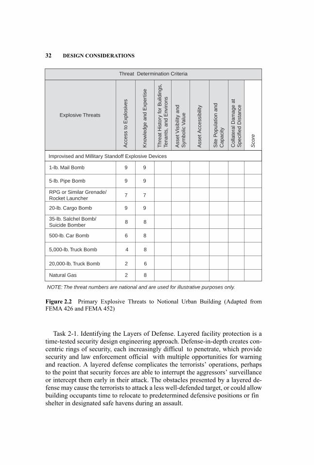
32 DESIGN CONSIDERATIONS
Threat Determination Criteria
Explosive Threats
1-lb. Mail Bomb 9 9
9 9
9 9
8 8
6
6
4
2
2
8
8
8
7 7
20-lb. Cargo Bomb
500-lb. Car Bomb
5,000-lb. Truck Bomb
20,000-lb. Truck Bomb
Natural Gas
NOTE: The threat numbers are national and are used for illustrative purposes only.
35-lb. Salchel Bomb/Suicide Bomber
5-lb. Pipe Bomb
RPG or Similar Grenade/Rocket Launcher
Acc
ess
to E
xplo
sive
s
Ass
et V
isib
ility
and
Sym
bolic
Val
ue
Ass
et A
cces
sibi
lity
Site
Pop
ulat
ion
and
Cap
acity
Col
late
ral D
amag
e at
Spe
cifie
d D
ista
nce
Kno
wle
dge
and
Exp
ertis
e
Thr
eat H
isto
ry fo
r B
uild
ings
,Te
nant
s, a
nd E
nviro
ns
Sco
re
Improvised and Millitary Standoff Explosive Devices
Figure 2.2 Primary Explosive Threats to Notional Urban Building (Adapted fromFEMA 426 and FEMA 452)
Task 2-1. Identifying the Layers of Defense. Layered facility protection is atime-tested security design engineering approach. Defense-in-depth creates con-centric rings of security, each increasingly difficul to penetrate, which providesecurity and law enforcement official with multiple opportunities for warningand reaction. A layered defense complicates the terrorists’ operations, perhapsto the point that security forces are able to interrupt the aggressors’ surveillanceor intercept them early in their attack. The obstacles presented by a layered de-fense may cause the terrorists to attack a less well-defended target, or could allowbuilding occupants time to relocate to predetermined defensive positions or finshelter in designated safe havens during an assault.
COLLABORATING TO ANALYZE RISK 33
The firs layer of defense in a typical urban setting is the surroundingarea—the sidewalks, curb lanes, streets, other buildings, and the neighborhooditself. The structural composition of adjacent buildings can either enhance theproject’s security or increase its threat. Local law enforcement and traffi author-ities are increasingly willing to support a security designer’s street and curb-lanesafety initiatives, particularly when realistic procedural measures precluding ad-jacent vehicle traffi lanes or parking are planned. Unobtrusive physical secu-rity devices—such as decorative anti-ram, crash-resistant street lights, benches,planters, and trash receptacles—are found often now on sidewalks and plazas.Embedded barricades, retractable bollards, and hydraulic barricades are also be-coming more commonplace.
The exterior space between the line of vehicle or pedestrian interdiction andthe project structure is the second layer of defense. Surveillance cameras andlighting must be part of any security design, but force protection engineeredvehicle interdiction devices and pedestrian approach restrictions can be usefulhere too. Crime Prevention through Environmental Design (CPTED),5 a mul-tidisciplinary approach to deterring criminal behavior, may also create a disin-centive to terrorist surveillance and operations. ASIS International,6 the societyfor professional security officers has extensive libraries of security equipment,concepts of operation, site civil and landscape counter-crime features, and oper-ational procedures-related information to help in security design planning of thisinterstitial area between the protected building and the site perimeter.
The third layer of defense is the building itself, and it is here that securitydesign measures can play a particularly effective role. Hardening structures, fa-cades, and systems; providing a broad array of alarm and surveillance tools;and carefully designing and locating utilities and building systems, incorporat-ing equipment that supports evacuation and recovery, are examples of criticalelements in security design. Subsequent chapters of this handbook expand ontopics such as the role of materials-performance criteria, structural systems de-sign, facade protection, and survivability of ERR systems.
Task 2-2. Identifying the Critical Assets. The second task of the asset valueassessment is to identify critical elements within each of the three defenselayers—in other words, which resources must withstand an attack if the healthand safety of the building’s occupants are to be ensured. FEMA and ASIS,among others, publish extensive checklists that will greatly assist in pinpoint-ing relevant issues.
Task 2-3. Identifying the Building Core Functions and Infrastructure. The se-curity design team should next identify the building’s, site’s, or venue’s corefunctions and infrastructure. The design team should use these data to informdesigns that isolate, distribute, or replicate the equipment and processes that will
5A discussion of CPTED, including numerous references and external links, can be found athttp://en.wikipedia.org/wiki/Crime prevention through environmental design.6ASIS can be found at www.asisonline.org.
34 DESIGN CONSIDERATIONS
provide vital operations and services during and after an attack, or designs thatuse hardening strategies to improve the operational survivability of these opera-tions and services.
One of the most successful strategies for the protection of building core func-tions and infrastructure in blast-protection design is dispersal and redundancy. Ifa bomb detonates adjacent to or within a facility, phones and telecommunicationsequipment, security and evacuation systems, fir suppression and smoke controlsystems, generators and uninterruptible power supplies, and other infrastructureelements deemed critical to evacuation, rescue, and recovery must continue tofunction. Here again, FEMA, ASIS, and others have developed extensive lists ofquestions to help assessment teams identify core security and life-safety func-tions and their interdependencies.
Task 2-4. Determining the Asset Value Ratings. The fina task in Step 2 is toassign a value rating to each asset. The value rating is the security design team’sjudgment of the degree of debilitating impact that would be produced by theincapacitation or destruction of that asset. In other words, the consequences ofdamage or destruction are considered for each asset. Then a 1-to-10, very-high-to-very-low value is assigned to each asset. “Very high” would mean that the lossor damage of the building’s assets would have exceptionally grave consequences,such as extensive loss of life, widespread severe injuries, or total loss of primaryservices, core processes, and functions. On the other hand, a “very low” rankingindicates that the loss or damage of the building’s assets would have negligibleconsequences or impact. As was previously noted, there are f ve additional gra-dients between these two extremes (Federal Emergency Management Agency2005, Table 2.5).
The asset value assessment lists the building’s core functions and critical in-frastructure elements. Next, the team assigns each element an intrinsic valuebased on the degree of debilitating impact that its incapacity or destruction wouldcreate. The product of the value asset rating exercise is a table that lists the var-ious types of attacks against each of the facility’s critical functions. The teamthen populates the table with high-to-low values expressing the consequences ofloss or damage of each asset.
2.4.3 Step 3—The Vulnerability Assessment
Vulnerability is any weakness that aggressors can exploit to cause damage. Toconstructively influenc design considerations, the vulnerability assessment mustrealistically appraise the building’s projected functions, systems, and site fea-tures; it must pinpoint structural weaknesses and identify absences of neces-sary redundancy so that corrective actions and mitigations can be incorporated.Unlike threats, vulnerabilities are conditions and/or designs that people createthemselves and over which they can therefore exercise some control. Close co-ordination among the assessment team, the building design professionals, andownership is critical; it is essential to prevent a great deal of incompatible expec-tations and design deliverables down the road.
COLLABORATING TO ANALYZE RISK 35
There are four tasks in assessing vulnerability:Task 3-1. Organizing Resources to Prepare the Vulnerability Assessment.
Task 3-1 has two subparts:
(a) Selecting the Assessment Team. Risk assessment is a complex undertak-ing with high stakes in terms of consequences and costs. Proper team se-lection requires some serious up-front time and attention, if only because,in unskilled hands, risk assessment tools can be blunt instruments. Thebest survey-tool authors stress that “teams created to assess a particularbuilding should be senior individuals who have a breadth and depth ofexperience in the areas of civil, electrical, and mechanical engineering;architecture; site planning and security engineering; and how security andantiterrorist considerations affect site and building design” (Federal Emer-gency Management Agency 2005, ii).
(b) Determining the Level of the Assessment. The security community gen-erally recognizes three increasingly detailed levels, or tiers, of risk as-sessment (explained below), so at this point a decision is required: howdetailed must the evaluation be?
FEMA 452 guidelines for vulnerability assessment denote three assessmentlevels:
Tier 1—A study that identifie the most important vulnerabilities and theirmitigation options—a “70 percent” assessment. A Tier 1 evaluation is typ-ically conducted in approximately 2 days by one or two experienced as-sessment professionals working with the building ownership and key staff.It involves a quick look at the site perimeter, building, core functions, in-frastructure, and any related drawings and specifications A Tier 1 assess-ment is likely sufficien for the majority of commercial buildings and othernoncritical facilities and infrastructure.
Tier 2—A full on-site evaluation by assessment specialists that provides arobust evaluation of proposed and/or existing systems’ interdependencies,vulnerabilities, and mitigation options—a “90 percent” assessment solu-tion. A Tier 2 assessment typically requires three to f ve assessment spe-cialists. It can be completed in about 5 days and requires significan keybuilding staff participation; access to all existing site buildings and areas,systems, and infrastructure; and/or an in-depth review of proposed build-ing design documents, drawings, and specifications A Tier 2 assessmentshould be sufficien for most high-risk buildings such as iconic commer-cial buildings, government facilities, cultural and educational institutions,hospitals, transportation infrastructure, and other high-value targets.
Tier 3—A detailed evaluation of the facility and site. A Tier 3 analysis usesblast and weapons-of-mass-destruction (WMD) modeling to assess the siteand building’s response, survivability, and recovery parameters. It involves

36 DESIGN CONSIDERATIONS
engineering and scientifi experts, requires detailed design information,and provides the maximum data for evaluating and developing mitiga-tion options. Tier 3 modeling and analysis can often take several weeksor months for an existing facility and is a process involved at the Con-ceptual, Schematic, and Design Development phases of new facilities. It istypically performed only for high-value and critical structures. From 6 to12 subject matter experts may be required, based on project complexity.
When the building and site are in the design phase and do not yet ex-ist, the risk assessment data-gathering process described above must bemodifie considerably. A Tier 2 risk assessment of a future building wouldconcentrate, for example, on conceptual design documents, drawings, andplans in an iterative process of discussion, impact assessment, and designor redesign. This situation is actually preferable, because it gives the designprofessionals an opportunity to build security into the structure’s skeleton.The alternative—retrofittin protection into inappropriate or inadequatespaces—seldom offers totally satisfactory solutions.
The choice of the appropriate tier level depends on the building andsite’s location, its construction characteristics, its proposed use and profileand its owners’ or occupants’ concerns about terrorism. The choice of tierlevel is also heavily influence by the design team’s initial threat and vul-nerability appraisals; by local, state, and federal antiterrorism and publicsafety regulations and guidelines; and (inevitably) by benefit- ersus-costconsiderations.
Task 3-2. Evaluating the Site and Building. The authors have described howproducing a robust building security design requires the team to identifypotential threats and vulnerabilities, defin the resources and people mostat risk, and describe the consequences of potential losses. To bring orderand predictability out of such complexity, the team’s next task is to preparea survey schedule and tentative agendas. The team needs, for example,to meet with stakeholders such as site or building owners, security andengineering personnel, IT directors, and emergency managers. The teamwill also need to inspect the area and facilities and review key informationsuch as security plans and emergency procedures, if these documents exist.The key to timely execution and success is planning.
An important aid to planning is threat mapping, the clear and graphicrepresentation of the site-wide explosive DBTs at vulnerable points, suchas lobbies, mailrooms, and loading docks. Threat maps, which are basedon architectural concept drawings, should encompass the site from its out-ermost perimeter to its most sensitive internal areas. This mapping can bedone on existing blueprints or other site drawings. Each vulnerable area islabeled with a “W” number, according to the key that has already been cre-ated for designating explosive DBTs (W-1, W-2, W-3, etc.). Threat mapsillustrate for design professionals how concentric layers of competently ap-plied security measures can reduce, or in some cases largely eliminate, thefacility’s explosive threats.
COLLABORATING TO ANALYZE RISK 37
Task 3-3. Preparing a Vulnerability Portfolio. It just makes good sense thatthe large volume of data that has been collected as part of the threat, risk,and vulnerability assessment in the previous steps should next be gatheredinto a well-organized security design document.
One of the most useful sets of assessment aids in this team portfoliocan be the FEMA Building Vulnerability Assessment Checklists found atAppendix A of the previously mentioned FEMA publication 452, Risk As-sessment: A How-To Guide to Mitigate Potential Terrorist Attacks. Thisseries of tables prompts the team to adopt a consistent approach to evalu-ating security designs at their various stages of development. The checklistcan be used as a screening tool for preliminary design vulnerability assess-ments and supports the preparation of each step in FEMA’sHow-To Guide.As the FEMA Guide explains:
The checklist is organized into 13 sections: 1) site, 2) architectural, 3) struc-tural systems, 4) building envelope, 5) utility systems, 6) mechanical sys-tems, 7) plumbing and gas systems, 8) electrical systems, 9) fir alarmsystems, 10) communications and information technology, 11) equipmentoperations and maintenance, 12) security systems, and 13) the security mas-ter plan. To conduct a vulnerability assessment or preliminary design, eachsection of the checklist should be assigned to an engineer, architect, or sub-ject matter expert who is knowledgeable and qualifie to perform an assess-ment of the assigned area. Each assessor should consider the questions andguidance provided to help identify vulnerabilities and document results inthe observations column. If assessing an existing building, vulnerabilitiescan also be documented with photographs, if possible. The results of the 13assessments should be integrated into a master vulnerability assessment andprovide a basis for determining vulnerability rating during the assessmentprocess. (Federal Emergency Management Agency 2005, Appendix A)
Task 3-4. Determining the Vulnerability Rating. The weaknesses the securitydesign team has identified which could be exploited during an explosivesattack, are reflecte in the vulnerability rating. As an example, the lack ofcritical-systems redundancy raises the vulnerability rating, of course, as dosingle points of failure among essential security and life-safety systems orstructural systems incapable of withstanding the project explosive DBTsor an unforeseen event that could compromise a key primary structuralelement.
Like the previous threat and asset value ratings, vulnerability scores are com-monly expressed in a 1-to-10 numerical scale or a very-low-to-very-high lin-guistic scale. A very high vulnerability rating is delivered from identifying oneor more major weaknesses that make the facility extremely susceptible to anaggressor or hazard. A very low rating describes a building that integrates excel-lent physical security and comprehensive redundancies—in short, a building that

38 DESIGN CONSIDERATIONS
would promise a high degree of physical and intellectual asset protection and beoperational immediately after an attack.
To summarize where the discussion is now in the risk assessment process:In light of the identifie potential threats (Step 1) and the team’s categorizationof the structure’s critical assets (Step 2), the vulnerability assessment (Step 3)determines the opportunities to place at risk the project assets, and therefore setsthe stage for (Step 4) the risk assessment, wherein the team and the client discussand agree to the extent of acceptable risk.
The vulnerability assessment is a comprehensive listing of all weaknesses anaggressor could exploit to damage an asset. The product of Step 3 is anothertable, this one listing the building functions, each one with its high-to-low vul-nerability rating, together with the associated vulnerabilities that the team hasuncovered.
2.4.4 Step 4—The Risk Assessment
This is the step in which the team pulls together all the information it has com-piled, all the tables it has completed, all the judgments it has made, and each ofthe threat, asset, and vulnerability ratings it has carefully assigned. This step iswhere the interdisciplinary teamwork pays off; the risk assessment, backed upby its demonstrable research, provides a credible foundation for security designdecisions.
Task 4-1. Preparing the Risk Assessment Matrices. Focusing attention on ex-plosive event protection naturally narrows the range of security-design consider-ations. If, however, the team wants to undertake an all-risk, all-hazard review, in-cluding chemical/biological/radiological attacks as well as cyberassaults, it canrefer to FEMA 452 for a range of helpful checklists. Whether the analysis isbroad or narrow, however, the way to estimate potential losses is to prepare a se-ries of matrices, tailored to the individual task at hand and based on the analysisconducted during Steps 1, 2, and 3.
To estimate risk, the team must have analyzed a number of factors. First, itwill have identifie and ranked the threats that could harm the project. Next,it will have determined the value of the client’s assets, including people whorequire protection. Finally, by using the results of the threat scores, asset valueestimations, and vulnerability ratings, it will determine a vulnerability and assetrating system that identifie weaknesses an aggressor could exploit.
Task 4-2. Determining the Risk Rating. The design team next analyzes thethreat ranking, asset value, and vulnerability rating developed in the previoussteps and assigns a risk level for each critical asset. A specifi risk such as a car-, truck-, or person-borne bomb can be expressed as the sum of the asset valuetimes the threat rating times the vulnerability rating, or R = AV × TR × VR.This exercise also results in linguistic or numeric values, or both.
Task 4-3. Prioritizing Vulnerabilities with FEMA’s Building Vulnerability As-sessment Checklist. With a risk level now assigned to each critical asset, the teamis ready to prioritize, or rank, the vulnerabilities it has identified Prioritization is
COLLABORATING TO ANALYZE RISK 39
based on evaluating which vulnerabilities the aggressors will most likely exploitand which of them pose the greatest danger to lives, structures, and operations.The highest ranking is given, obviously, to the greatest vulnerabilities with thegreatest consequences. Doing so makes it possible, in the next step, to determinethe most effective mitigation measures.
2.4.5 Step 5—Considering Mitigation Options
After completing the risk assessment, stakeholders are frequently left with issuesrequiring mitigation, but they fin their options limited by space constraints, es-thetics, regulatory requirements, or costs. Decisions about allocating resourcestherefore must focus on the most practical mitigation options.
These are the fundamental mitigation questions:
1. What kind of action should be taken in response to the danger? There arefour ways of responding to a threat:� Acceptance of a threat is a rational alternative that is often chosen whenthe threat has a low probability, low consequence, or both.
� Prevention is the alteration of the target or its circumstances to diminishthe risk that the terrorist or criminal will succeed.
� Interdiction is any confrontation with, or influenc exerted on, an at-tacker to eliminate or limit its movement toward causing harm.
� Mitigation is preparation so that, in the event of an explosion, its conse-quences are reduced.
2. Does the response create new risks to the asset or others? The fina stepin analyzing the security program’s effica y is to be aware of new riskscreated by the prevention, mitigation, or interdiction of the threats underconsideration.
Four tasks are involved in identifying mitigation alternatives:
Task 5-1. Identify Preliminary Mitigation Options. This exercise identifie thedesign team’s available design options together with any relevant physical,technical, cyber, and procedural security alternatives. The goal is to createthe strongest possible security design.
Task 5-2. Review Mitigation Options. Since every project has budget con-straints as well as operations and maintenance limitations, it is seldompossible to totally eliminate a risk. Now is the time, therefore, to weighmitigation options for their practicality and to match the most feasible mit-igation opportunities with the most critical risks.
Task 5-3. Estimate the Cost. Some costs of protecting buildings are fi ed,while others are variable. Funds for deploying protective equipment andcreating a security zone-of-control are generally fi ed; for example, the
40 DESIGN CONSIDERATIONS
costs of anti-ram barricades to keep a vehicle away from the facility arecomparable whether the same vehicle contains 50 pounds of TNT or 500.The blast-protection costs of facility construction, on the other hand, willvary according to the estimated threat level. Since the bomb size is outsidebuilding planners’ control, the tailoring of blast protection to the buildingstructure, for instance, is a function of the maximum credible explosivecharge plus its estimated proximity when the bomb detonates.
Since cost is almost always a central issue, there are three mitigation ap-proaches that can be used singly or in combination: (1) modify the design threat,(2) reduce the level of protection, or (3) accept the risk. Life-cycle costs needto be considered as well. For example, the recurring costs of maintaining andupgrading security and life-safety equipment can derail even the best protectiveprograms.
Security design experience has repeatedly shown that attention paid to de-fending against man-made hazards during the preliminary planning and concep-tual design phases significantl reduces the life-cycle costs of protection andincreases the inherent security level provided to the building occupants.
In summary, the project security professionals’ explosive threat assessmentshould figur prominently in the design of the facility facade, structural system,ERR systems, and other critical protective features. The design team should bedirectly involved in the risk assessment steps that identify which building designfeatures and components can affect the type, size, and potential delivery methodof an explosive device.
Task 5-4. Reviewing Mitigation, Cost, and the Layers of Defense. FEMA 452includes a fina series of tables containing examples of mitigation optionsand alternatives for each of the facility’s security features. These securitymeasures are organized by layers of defense and arrayed by degree of pro-tection, cost, and effort. See Figure 2.3 below for FEMA 452 (January2005) Worksheet 5-1: Preliminary Mitigation Options.
When the team has completed the risk assessment process, it will have identi-fie and evaluated various mitigation options it can use as guidance when devel-oping the building’s protective design features and components.
2.4.6 The Continuing Role of Risk Management
The goal of stronger, safer structures begins with building security design andcontinues as security risk management throughout the building’s life cycle. Tosupport these initial and long-term goals, FEMA 452 asserts that the goal of theassessment process is to achieve the level of protection sought through imple-mentation of mitigation measures in the building design. These measures mayreduce risk by deterring, detecting, denying, or devaluing the potential threatelement prior to or during execution of an enemy attack. The Department of
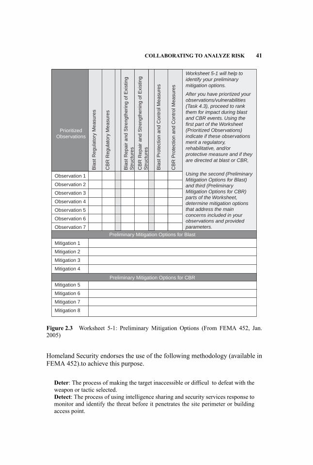
COLLABORATING TO ANALYZE RISK 41
PrioritizedObservations
Observation 1
Worksheet 5-1 will help toidentify your preliminarymitigation options.
After you have priortized yourobservations/vulnerabilities(Task 4.3), proceed to rankthem for impact during blastand CBR events. Using thefirst part of the Worksheet(Prioritized Observations)indicate if these observationsmerit a regulatory,rehabilitative, and/orprotective measure and if theyare directed at blast or CBR,
Observation 2
Observation 3
Observation 4
Observation 5
Observation 6
Observation 7
Mitigation 1
Mitigation 2
Mitigation 3
Mitigation 4
Mitigation 5
Mitigation 6
Mitigation 7
Mitigation 8
Bla
st R
egul
ator
y M
easu
res
CB
R R
egul
ator
y M
easu
res
Bla
st R
epai
r an
d S
tren
gthe
ring
of E
xist
ing
Str
uctu
res
CB
R R
epai
r an
d S
tren
gthe
ning
of E
xist
ing
Str
uctu
res
Bla
st P
rote
ctio
n an
d C
ontr
ol M
easu
res
CB
R P
rote
ctio
n an
d C
ontr
ol M
easu
res
Using the second (PreliminaryMitigation Options for Blast)and third (PreliminaryMitigation Options for CBR)parts of the Worksheet,determine mitigation optionsthat address the mainconcerns included in yourobservations and providedparameters.
Preliminary Mitigation Options for Blast
Preliminary Mitigation Options for CBR
Figure 2.3 Worksheet 5-1: Preliminary Mitigation Options (From FEMA 452, Jan.2005)
Homeland Security endorses the use of the following methodology (available inFEMA 452).to achieve this purpose.
Deter: The process of making the target inaccessible or difficul to defeat with theweapon or tactic selected.Detect: The process of using intelligence sharing and security services response tomonitor and identify the threat before it penetrates the site perimeter or buildingaccess point.

42 DESIGN CONSIDERATIONS
Deny: The process of minimizing or delaying the degree of site or building infras-tructure damage or loss of life or protecting assets by designing or using infras-tructure and equipment designed to withstand blast and chemical, biological, orradiological effects.Devalue: The process of making the site or building of little or no value or conse-quence, from the terrorists’ perspective, such that an attack on the facility wouldnot yield their desired result (FEMA 452, 2005).
2.5 CONSEQUENCE MANAGEMENT
This section provides insight into one of the primary tools used in assisting de-sign professionals and their clients in the development of decisions involvingrisk management. This section explores the value and process of evaluating con-sequences associated with explosive events and the major mitigating strategycategories used to reduce those consequences.
Consequential effects are, by their very nature, subjective evaluations and cat-egorizations. The perception of what is and what is not valuable and/or essentialis very much determined by the valuation process utilized by the institution ororganization that is responsible for its codification Consequently, institutionalbusiness mission statements, private organizational charters, government agencyprograms, stockholder expectations, legal proscriptions, and numerous otherguidelines and/or mandates often identify different levels of expectation for post-event facility performance. These guiding documents and/or unwritten notionswere generally not created for the purpose of assisting design professionals byclearly definin ownership’s requirements for preserving institutional business-mission operations or the protection of people on premises. The absence of well-codifie protection expectations leaves the design team with less than adequateinformation about the extent of consequential effects that ownership will fintolerable.
Design professionals must clearly understand the goals and expectationsof the facility, its occupancy and the activities that will take place withinthe structure, site, and, in some cases, the campus or regional landscapeor cityscape fabric they are creating for (and with) their client. This is anessential piece of early project information client data mining, which is of-ten overlooked. Insufficien efforts and pursuit of a clear definitio of clientdesires regarding consequence management are one of the most significandesign process shortfalls. Mismanagement of this process will likely predes-tine the engineering efforts to fail to meet client needs or expectations.
To address this omission in the programming design phases, one of the firssteps should be—during the earliest phases of project design programming andconceptualization—the creation of a brief security design mission statement.This document should clearly and concisely state the client’s expectations forthe facility’s post-explosive event performance. These expectations are routinelyoverstated by clients. This is generally a result of their lack of sophistication or
CONSEQUENCE MANAGEMENT 43
knowledge of the engineering complexities, architectural program compromises,post-construction institutional operational constraints, impact on project financials, aesthetic effects, and other factors better understood by the structural en-gineer and the balance of design team professionals. Consequently, this missionstatement must be a consensus-developed document. It is reasonable to expectthat it may take several iterations of authorship, editing, review, and subsequentapproval.
Once agreed to, the consequence management statement should then be-come a part of the project’s key design assumptions and design programobjectives. It should be used as a means to guide design decisions, and toprovide the basis for decisions regarding program conformance, as designsmature in the Schematic, Design Development, and Construction Documentphases.
Once a clear concept of acceptable consequence management in terms of fa-cility performance is understood and codified there is a sound basis for develop-ing the facility designs. This is essential to the process of achieving an acceptablebalance between post-explosive event damage to the facility’s physical and intel-lectual assets and the expectations of the client and society regarding life safetyand institutional business-mission continuity.
No facility can be expected to provide a post-explosive event damage per-formance profil that ensures no injury, no loss of life, and no disruption tofacility operations. The challenge of consequence management is for thedesign professional and client team to establish reasonable goals and ob-jectives. These need to be tempered by rational opportunities for successgiven the facility’s design program, client occupancy and activities, projectlocation and budget, law enforcement and security resources, and other eco-nomic and geopolitical factors, which are unique and specifi to each designcommission.
Design professionals and their clients have opportunities to examine and im-plement strategies that can participate in achieving the level of consequence man-agement identifie in the project’s key design assumptions and design programobjectives, as stated above. These holistic design strategies usually include:
(a) Strategic site selection and facility location to reduce vulnerability tothreats that are on-site, near-site, or regional.
(b) Within a specifi building, the provision of equipment, personnel, and re-source redundancies, so that the loss of a single critical system, facilitymanagement operational component, or structural element or system doesnot create a single point of unacceptable or catastrophic failure.
(c) Within a specifi building, distribution of facility physical plant; intel-lectual and nonintellectual assets; operational programs; and evacuation,rescue, and recovery systems so that an explosive event in one loca-tion does not jeopardize the entire building, all of its occupants, and thefacility-wide performance of ERR systems. (Note, however, that the use of
44 DESIGN CONSIDERATIONS
diverse redundancy as a protective strategy should be examined during thedesign process in conjunction with the protective strategy of co-location ofcritical systems and/or resources housed within a well-protected environ-ment. The intent is to foster survivability, thereby reducing consequentialeffects.)
2.5.1 Consequence Evaluation
It is universally understood by the architectural and engineering design commu-nity that explosive events can be responsible for significan damage to buildingstructures, facades, and critical building systems. However, there is less aware-ness amongst the design profession during the initial planning phases of otherextremely important and sometimes ethereal values such as an institution’s pub-lic image and sense of solidarity. Without this awareness there is naturally lessacceptance of design responsibility for the protection of these other, less tangiblebut extremely important client assets.
Additionally, other more essential issues associated with evacuation, rescue,and recovery operations generally are assumed by the design profession to beowner and operator responsibilities developed by those entities in response tothe building’s design. This approach is archaic.
Design professionals must address building designs so that the explosiveevent consequence management response is achieved through an evaluationof how evacuation, rescue, and recovery operations will occur after the ex-plosive event. In this way, designs are informed to protect evacuation, res-cue, and recovery building design features such as stairways, exit passage-ways, elevators, and building systems such as emergency power, emergencylighting, voice evacuation, fi e detection, fi e suppression, and smoke man-agement. This consequence evaluation approach results in a building designthat provides inherent tactical support and definit ve criteria for an evacu-ation, rescue, and recovery concept of operations. This will always providea superior product to an ERR strategy retrofitte to a design created withless inherent vulnerability.
The above design shortfalls can generally be attributed to the design team’sfocus on the intimate knowledge of and extensive involvement in developingall of the intricate details associated with each component of the building’s ar-chitectural, structural, and support system infrastructure designs. Furthermore,the design community traditionally focuses on contract boundary limits as theextent of their responsibility for the ultimate scope of their work. The rangeof effects from explosions rarely aligns with contract boundary limits ofwork. This fact must be taken into consideration as part of consequenceevaluations.
Facility occupancy after construction completion, with its complement of staffpopulation assignments, support furnishings and equipment, and operational pro-tocols usually is established with the greatest attention to detail after the buildingis commissioned. Consequently, these and other aspects of day-to-day facility

CONSEQUENCE MANAGEMENT 45
management are logistically more distant entities and often are understood inless detail by the design professional team. Design professionals should focusadditional resources on more completely understanding post-constructionoccupancy and fit-ou subtleties, in order for explosive event consequenceevaluations to be more thoroughly responsive.
Also, traditional contracts, governing the performance of the design team’sscope of work, emphasize the most significan levels of effort up to and inclusiveof building commissioning. They fall short of emphasizing the role of the designprofessionals in fully understanding a broader range of construction completionand subsequent facility occupancy concerns. These include all of the various in-tellectual and operational entities, exceptional conditions and crisis management,and facility restoration issues, which will be placed at risk and/or hindered by anexplosive event once the structure is completed. Understanding how the fa-cility will operate under extraordinary conditions is essential to developingprotective designs that address the consequential effects on occupants andoperations, as well as on the physical plant.
The structural engineering, architectural design, and balance of the de-sign team professionals should ensure, at the commencement of the designprocess, that this disparate intellectual appropriation of design awareness isaddressed. This should be accomplished through a process that focuses onthe protection and post-explosive event performance of the structure itselfin a manner that is carefully balanced against all of the other consequen-tial explosive event effects, including day-to-day facility operations and theexceptional conditions associated with ERR.
A wide range of consequences must be evaluated. Understanding these con-sequences is critical to establishing the balance between (a) protective designsassigned to the facility’s site perimeter protection program, facade, structure,evacuation, and rescue and recovery systems and (b) systems associated withlife safety and business continuity. Mitigating each of the consequences thatmay occur if these areas of facility vulnerability are not adequately addressedwill require a portion of the project’s budget. The project profil for securityinvestments will in large part be determined by the consequence evaluationprocess. This process can be logically approached and informed by an eval-uation of the following areas of explosive event influence
Site and Local Risk Management Context Although design professionalsare traditionally charged with protective designs for the specifi contracted-forclient facility, explosive events routinely involve collateral damage to adjacentstructures and/or public spaces and also place these additional lives and propertyat risk. This is a fact that cannot be ignored. The performance of the clientfacility must be considered within a regional context in order for the client andthe design team to exercise the highest standard of industry care and to reducethe extent of design professional liability. The creation of a highly protectedfacility that exclusively focuses on protection of that specifi facility’s assetsand does not take into consideration how its performance may affect adjacent
46 DESIGN CONSIDERATIONS
structures, public spaces, and their populations cannot be considered the mostprudent design solution.
Facility Structural System Protection of the facility’s primary and secondarystructure from progressive collapse and disproportionate damage associated withexplosive events external or internal to the building is a baseline protective de-signconsideration in consequence evaluations. Catastrophic failures of an entirestructure or a significan portion of it generally place large occupant populationsat risk, both as a result of the immediate event effects and of disruption to ERRoperations. Additionally, these structural failures invariably cripple critical busi-ness missions, sacrific institutional operational viability, and adversely affectrestoration of day-to-day operations.
Facility Facade System Explosive events, either internal to or external to thebuilding, are likely to engage the facade in managing applied forces significantlin excess of the thresholds associated with conventional wind, seismic, and grav-ity loading. This routinely results in catastrophic glazing and glazing systemfailures, which are historically responsible for significan loss of life and injuryto both occupants within and external to the targeted facility. Airborne glassfragmentation continues to be identifie as one of the most lethal aspects ofbuilding component responses to explosive events.
Facility Evacuation, Rescue, and Recovery Systems While the immediate dev-astating effects of explosive events can be limited by protective design strategies,post-event evacuation functions and the subsequent activities of rescue and re-covery are dependent upon the integrity of stairs, vertical transportation systems,power, lighting, voice communication, smoke management, and other systems.These systems can be placed out of service throughout the building or sufferdisproportionate damage if they are not specificall designed in response to theproject design basis explosive threats.Maintenance of these critical ERR sys-tems, outside of the immediate explosive event zone, is essential to reducingthe extent of resulting lethality, injury, and facility disruption. Design pro-fessionals, when evaluating explosive event consequences to ERR systems andoperations, must take into consideration that these systems may be exposed tosupplemental damage due to structural instability. Also, that extraordinary (ter-rorist) criminal event modalities have historically been strategically planned sothat phased explosive events occur with the purpose of targeting emergency re-sponders and those residual occupants on the scene who have not yet been evac-uated.
HVAC Systems Explosive events are traditionally accompanied by the devel-opment of significan quantities of airborne particulate contaminants, includingglazing fragmentation, toxic materials, and other byproducts of building compo-nent demolition. These are inevitably deposited within the HVAC system as aresult of system breaches associated with the explosive event, or as a result of

CONSEQUENCE MANAGEMENT 47
fans continuing to operate after the explosive event. This contamination can beof such significanc as to warrant the demolition and entire replacement of theHVAC fan systems (including filters coils, etc.), fan plenums, and distributionduct work.
Business Continuity The design professional community should naturally ad-dress issues of life safety as a firs priority. However, considerations for institu-tional business continuity cannot be ignored as part of the initial consequenceevaluation process, and may in fact be a client’s most clearly stated objective.The extent of the business continuity protective design mandate will depend uponthe client’s mission statement and expectations. It will also be dependent uponthe extent of resources available to provide building protective design strate-gies beyond those required to achieve the consensus of life-safety performancestandards. In general, clients’ expectations regarding the financia benefitof business continuity are well stated. However, ownership routinely antici-pates that the building codes and design professionals’ experiences will ade-quately guide the design in the protection of occupants on site. This potentialdisparity in consequence management expectations must be identifie andaddressed accordingly.
Restoration of Operations Explosive events are violent conflagration with thepotential to significantl disrupt facility physical plant, affect life safety, andviolate viable occupancy. Every explosion will be initially treated by the lawenforcement community as a crime scene, by the building department as a po-tential condemnation, by underwriters as a time for claim investigations, andby others as the site of numerous activities other than those originally intendedas part of the building’s use profile There will be an inevitable period of in-vestigation and severe facility occupant access restriction. Design professionalsshould engage the client in post-explosive event consequence evaluations.These should very specificall focus on the extent of post-event facility de-molition and restoration that is tolerable in order to meet client expecta-tions regarding facility condemnation by the local building authority, theanticipated time and cost of reparations, and the extent of time required toreestablish baseline business-mission operations.
Target Attractiveness To the extent that crimes involving the use of explosivescan be deterred, a significan advantage can be achieved. While there are no spe-cifi predictive mechanisms that can be referenced as an engineering and designguideline for criminal deterrence, especially for extraordinary (terrorist) attacks,the concepts of target hardening and inaccessibility are universally accepted bythe law enforcement and intelligence agencies as rational approach strategies forcrime reduction. Consequence evaluations should consider, at all stages ofdesign, whether the facility will be an appealing target. It is especially im-portant that target attractiveness be considered in the earliest phases of siteselection and facility location within the site. Also, the extent of accessibility
48 DESIGN CONSIDERATIONS
and opportunity for an aggressor to deliver the explosive to the target needsevaluation. Reduction in the perceived opportunity to achieve both of these po-tentials is a design goal worthy of substantial consideration.
2.5.2 Function Redundancy
This subsection identifie and provides insight into the benefit associated withthe management of post-explosive event consequences through the applicationof redundancy in various building architectural elements, programmatic spaces,and/or building systems. Incumbent on the discussions regarding redundancy isthe necessity to advance the concept of locational diversity, as adjacent redundan-cies are not efficien managers of consequences from an explosive event. Simplystated, adjacent assets are most likely to suffer the same damages.
This subsection text includes the identificatio of building systems involvedin evacuation, rescue, and recovery, and discusses how redundant ERR systemsmay reduce the requirement for structural hardening or may otherwise informstructural concepts, while reducing consequential effects. This is essential asERR systems have a primary role in enhancing facility life safety in responseto an explosive event and the secondary consequences of such a circumstance.
This subsection also addresses business mission-critical systems and spacesand how redundancy and diversity of these systems may beneficiall affect struc-tural and facade designs from the standpoint of explosive event protection. Otheraspects of redundancy associated with building components, systems, or pro-gram spaces are also discussed with a focus on how they may inform the struc-tural designs in terms of acceptable post-explosive event effects.
The subject of structural redundancy, for primary and secondary structuralelements, is not covered in this subsection, as it is the specifi subject matter ofother chapters in this handbook.
A primary facility performance goal for the design professional is to ensurethat evacuation, rescue, and recovery systems remain operational outside of thespecifi area of influenc associated with the project-specifi explosive designbasis threat event. This is a significan challenge since there are a number ofsystems that participate in ERR. Design professionals should anticipate that thefollowing systems, at a minimum, are considered part of the ERR protectionstrategy:
1. Fire suppression systems, including their water supplies2. Fire alarm, detection, exiting, and annunciation systems3. Emergency voice communication systems4. Emergency lighting systems5. Video surveillance systems supporting ERR spaces and operations6. Emergency way-findin and exiting systems (other than exit signage)7. HVAC chemical, biological, and radiological (CBR) agent control
CONSEQUENCE MANAGEMENT 49
8. HVAC smoke control, purge, and pressurization systems9. Elevators designated for Fire Department use10. Access control systems engaged in emergency exiting11. Fire and security command and control facilities12. Emergency power systems supporting the systems listed above13. Emergency exiting stairs and passageways
These are complex systems, with components distributed throughout a build-ing. The opportunity for their disruption is high as a result of the high-energydevastation characteristic of an explosive event. Consequently, their survival out-side of the immediate explosive event zone will depend upon significan invest-ments in hardening of walls and slabs to protect both the front-end monitor andcontrol portion of these systems and their extensive and pervasive distribution in-frastructure. Consequently, this is rarely the most economical approach. It is alsoleast likely to provide reliability equivalent to that of a design that implementsredundant systems located with geographic diversity, whose extent of segrega-tion is based upon informed explosive event calculations and modeling. In sum-mary, placing critical ERR system components outside of the blast effectzone is more often a more survivable and robust solution than attempting toprovide a hardening strategy to overcome single points of vulnerability andconsequent failures.
Business-mission continuity depends upon the survival of critical systems,equipment, information, and intellectual resources. Consequently, they must belocated within safe and secure spaces that are appropriately designed for humanoccupancy and provide conditions that do not exceed the systems’ thresholds ofenvironmental tolerance. These are fragile components, systems, and/or condi-tions that are as susceptible to disruption or compromise from an explosive eventas the previously discussed ERR systems. Depending upon the type and extentof service and/or product provided by the institution, there may be a require-ment for protecting a particular portion of or, alternatively, the entire facility.Design professionals, in the Preliminary Planning and Conceptual Designphases, will need to partner with the client and determine the extent of thefacility that must remain free of explosive event effects (as well as exteriorsupport infrastructure) in order to achieve the client business continuityexpectations.
If a backup project site protective design approach is not identifie as a viableoption (see Section 2.5.4), then the strategy of individual physical and intellec-tual asset protection will need to be compared to a strategy employing redundantsystems and personnel support within the project facility. These will need to belocated at a dimensional separation established by informed explosive event cal-culations based upon the project explosive design basis threats and the locationswhere these threats can be delivered. These locations will be dependent upon thefacility’s security program. Where local hardening options exist, they should be
50 DESIGN CONSIDERATIONS
carefully examined and a determination made as to whether they are the mostcost-effective and reliable approach to a robust business continuity design con-cept. If so, then critical business operations and their support systems can beconfine to a compact and unifie occupancy program within a locally hardenedportion of the structure.
External explosive events may place significan portions of a building’s fa-cade at risk, and the failure mode may involve large portions of the exteriorenvelope. Based on the explosive event specifics including the threat assessmentexplosive DBTs, standoff, and architectural envelope design criteria, post-eventfacade response may involve significan inbound facade debris that could neg-atively impact life safety, ERR operations, and business continuity programs.Design professionals, in the Preliminary Planning and Conceptual Designphases, should partner with the architectural team and develop preliminaryERR design strategies, informed by facade explosive event experience, sothat determinations regarding facade hardening versus redundant diverseERR systems are given due consideration and the proper balanced solutionselected.
While ERR components and operations and business continuity mission ex-pectations traditionally receive the majority of design focus for protection froman explosive event, client requirements may dictate that other physical, intel-lectual, or operational assets survive the DBTs. To address this additional re-quirement, design professionals will need to clearly understand the type and lo-cations of assets at risk. Subsequently, the post-explosive event architectural,structural, mechanical, electrical, and other related systems’ performance re-quirements will need to be define in a manner responsive to the asset protectionprofil . Based on the complexity of the necessary support infrastructure, de-sign professionals should conceptually investigate the option of individualsystem hardening versus redundant support systems at geographically di-verse locations outside of the calculated explosive event effect zone. Even ifa redundant diverse support system is selected, it should be recognized that lo-cal hardening will likely be required at points of connectivity to the protectedspace(s).
In some cases, functional redundancy is not an option. The preservation ofunique cultural artifacts, the protection of unique financia assets, co-located in-tellectual resources, critical unique industrial or financia processes, and othersingle-source assets do not allow the design professional the benefi of protec-tion through diverse repetition. These will require competent hardening strate-gies specificall created in a manner responsive to each asset’s vulnerability.
A discussion of functional redundancy and diversity, and mitigation strate-gies involving an analysis of hardening versus repetition and separation is notcomplete without consideration of effective strategies to preclude the introduc-tion of explosives to the facility or to assets at risk, through the implementa-tion of a competent security program. Design professionals should vigorouslypursue with ownership opportunities for threat reduction. The potential forimplementing this approach will yield a more secure facility with greater
CONSEQUENCE MANAGEMENT 51
functional capability for ERR and the least threat to business continuity orother single-source, high-value assets.
2.5.3 Building Location
This section explores and define the opportunities that the structural and blastconsultant engineers have available to assist the client in understanding the struc-tural, architectural, site civil, constructability, cost, schedule, and operational im-pacts associated with explosive event protection during the site selection process.
Design professionals are generally given the opportunity to assist a client insite selection, or, alternatively, are asked to develop the best structural protectivedesign response for a building on a particular client preselected site.
Site selection criteria will be influence by the threat assessment as identifiein Section 2.4 of this handbook.
When design professionals are engaged to work with the client on iden-tifying the suitability of a site, or sites, and the placement of a structure onthose site(s), the decision should be informed by a competent and thoroughthreat and risk assessment. This assessment must clearly address the qualitativeexplosive threats (vehicle-borne, man-portable/satchel, maritime vessel– deliv-ered, airborne delivery, standoff military ordnance, etc.), the quantitative designbasis threat values (amount of TNT equivalent for each of the threats identifiedshaped or unshaped charge, etc.), and the extent of opportunity for establishingstandoff between the threats and the protected facility. These are discussed inmore detail in Section 2.4.
Similarly, when clients request that design professionals work within a givenpredetermined site (i.e., when informing the site selection process is not part ofthe design professionals’ responsibilities), the limitations which that specifi sitewill impose upon the structural engineers and other design professionals shouldbe identified This should be based upon the risk assessment results associatedwith an assessment performed for that specifi site.
Site selection and building placement locational consequences can be ad-dressed through a competent process of explosive event analysis. This analysismust be informed by the threat assessment. It should also be informed by stand-off distance determinations, the evaluation of the resulting extraordinary loadsimposed upon the facility by the explosive event threat, and the opportunities formitigating strategy protective design concepts available to the design team.
Elimination of the explosive event threat remains the most attractive,competent, and cost-effective process in developing designs for facilities onany site. However, based on the threat assessment, it may be unreasonable toassume that the facility will not be exposed to explosive event effects. Mainte-nance of standoff between the explosive device and the asset remains as oneof the most powerful mitigating strategies available to the design team forthe development of a structure that affords the best opportunities for riskand consequence management. In the case of standoff military weaponry (suchas shoulder-fire ordnance), should it be identifie in the threat assessment as a

52 DESIGN CONSIDERATIONS
design basis threat, standoff distance will likely be less important than obscur-ing line of fire the provision of a predetonation screen, or the provision of othermeasures, as this form of attack can take place from a considerable distance.
In general, applied pressures and the duration of their application (impulse) tothe structure drop off exponentially as the distance between the protected struc-ture and the explosive event increases. The protection of the facility’s facade;primary and secondary structure; evacuation, rescue, and recovery systems; busi-ness continuity–related intellectual assets and physical plant; and other preiden-tifie entities worthy of protection will require a high level of design sophistica-tion. The design process will need to balance budget allocations and architecturaland structural design responses based upon the achievable standoff between theassets to be protected and the explosive event delivery location.
As part of the site selection process, the blast consultants, working withthe threat assessment identifie DBTs, should work closely with the clientand design professional team. This process should establish the pressuresand impulses that will be applied to the structure, its facade, inbound utili-ties, and other critical site civil features, based on the maximum achievableand realistic standoffs. This is essential so that an initial determination can bemade on how these extraordinary loads (in excess of gravity, wind, and seis-mic) will affect the protective design capabilities of the following major buildingsystems and/or afford protection to the following building components and oc-cupants:
1. Major/critical inbound utilities, such as fir protection water service, utilityelectrical power, information technology and data services, domestic water,steam, and gas
2. Facility access control points for vehicular entry3. Site-located critical utilities such as transformers, generators, cooling tow-
ers, fuel storage, domestic and fir service water storage, and communica-tions infrastructure
4. Facility facade5. Facility primary and secondary structural systems and elements6. Vertical transportation systems, including stairs, escalators, and elevators
internal to the building (these may be exposed to explosive event effectsshould the robustness of the facade design be less than the DBT eventcalculated pressures and impulse loads)
7. Evacuation, rescue, and recovery systems as identifie previously, in Sec-tion 2.5.2, internal and external to the building (these may be exposed toexplosive event effects should the robustness of the facade design be lessthan the DBT event calculated pressures and impulse loads)
8. Occupants within the facility9. Business mission-critical systems and equipment located within and/or ex-
ternal to the facility
CONSEQUENCE MANAGEMENT 53
The opportunity to achieve maintenance of standoff between the explosiveDBTs and the project assets, as noted above and as supplemented for each spe-cifi project, should be one of the primary focuses of the site selection process.This should involve a careful evaluation of how the explosive device deliverythreat, as identifie in the threat assessment, can be competently separated fromthe asset(s). Rational solutions involving vehicle anti-ram perimeters, pedestrianinterdiction barriers, and other site civil and landscape features should be con-sidered for their implementation feasibility. Inability to institute these protectivefeatures may have consequences on the building’s design. Consequently, the fol-lowing strategies should be considered:
1. To increase survivability of critical inbound utilities, and, therefore, the re-liability of ERR systems and operations, business continuity, and the mit-igation of secondary event effects (such as the ignition of a gas main as aresult of the explosive event), these utilities should be located outside ofan explosive event delivery zone. Alternatively, they should be providedwith hardening protection and redundant diverse routing at dimensionalseparations identifie by the blast engineer. Utility exposure and explo-sive event survivability evaluation is an initial critical design determi-nation, as it may inform substantial work and expenditure for utilityhardening protection or diverse routing and/or establishing long leadtime approvals and/or feasibility studies by local utilities.
2. To increase protection for building occupants, ERR systems, criticalbusiness-mission operations, and other predetermined internal assets, thefacade system for the building should be reviewed for its ability to be de-signed to reduce the threat of airborne fragmentation to both internal build-ing occupants and those external to the building. This should include a de-termination as to whether a design can be implemented whose post-eventperformance will be adequately robust to preclude additional protective de-sign measures internal to the building, or whether the failure mode requiressupplemental protection of internal and external assets. Facade robustnessevaluation is a critical initial design determination, as it will influencthe building’s architectural aesthetic, internal space program assign-ments, and the dedication of additional expenditures for hardeningand/or diverse redundancy of ERR and business mission-critical sys-tems.
3. Initial structural design concepts should be evaluated for their ability toincrease the survivability of the primary and secondary structure, and, con-sequently provide significan enhancements in life safety and business-mission continuity, and reduction in both decontamination and restorationtime to resume normal operations. These conceptual structural systemsshould be reviewed for their ability to be resistant to progressive collapseand disproportionate damage, based on the building location and the avail-able standoffs. Structural system survivability is a critical initial design
54 DESIGN CONSIDERATIONS
determination, as the type of structural system for the building may,in fact, be determined by explosive event management, in lieu of beingconceived to address traditional gravity, seismic, and wind loadings,in order to achieve the post-explosive event performance results. If aconventional structural system cannot satisfy the security performance re-quirements, then site selection and/or building placement on the site mayhave blast protection requirements that inform member sizing, connec-tions, standoff, and other major portions of the design with consequentialeffects on construction schedule, budget, and the architectural program.
4. To ensure the most competent and effective means to facilitate evacua-tion, rescue, and recovery operations, the designers should evaluate egress,emergency responder vehicular access, and emergency responder entry.This should be performed through a process of establishing their expo-sure to the project explosive DBTs and the separations/standoffs that canbe provided by the particular site. Vehicular access points to the site, ap-proach configuration to the facility, and the conceptual location of exitstairs and elevators should all be reviewed for survivability. The surviv-ability of ERR facility components is a critical design determination,as it may informmajor aspects of the site civil and landscape plan, andthe location, quantity, and type of the facility’s vertical transportationsystems, as well as the hardening required for these systems.
2.5.4 Building Dispersal/Distribution of Functional Programs
This subsection addresses the opportunities for consequence evaluation and man-agement associated with the physical separation of internal building programspaces, critical ERR and business continuity support systems, and physical as-sets and occupants. It focuses on the relationships among facility vulnerability,facility diversity (geographically diverse facility entities and, also, redundancyand diversity of internal building assets at a single site), the blast analysis pro-cess and the associated analytic results, and how these factors and engineeringanalytics can inform whether physical separation and the resulting diversity area more rational protective design solution than co-location and structural, archi-tectural, and ERR system hardening.
The threat assessment process discussed earlier identifie credible threats ap-propriate for mitigation. If explosive event threats are subsequently identifiedthen both the site selection and facility design process will need to address theirvulnerability to the specifi explosive event types, design basis threat quantification, the means of delivery, and their adjacency to the protected asset.
Vulnerabilities will occur wherever the explosive event threat can be deliv-ered at distances determined by the blast consultant to impose pressures, im-pulses, soil movements, and other explosive event effects in excess of the loadsprescribed for management by the building code. Additionally, vulnerabilitiesmay exist where these explosive events create conditions in excess of the criteria

CONSEQUENCE MANAGEMENT 55
stipulated in the client’s published design standards for project performance. Itis essential for a qualifie blast consultant to inform the design team of theseextraordinary loads, vibrations, soil displacements, and other consequentialeffects, and the distances at which they will be applied to the facility’s struc-ture, facade, and critical systems. These values should not simply be obtainedfrom resource and reference materials unless they are reviewed and subsequentlymodifie and/or approved by a qualifie explosives and structures subject matterexpert with extensive experience and access to government-approved computermodeling software.
Subsequent to the identificatio of the anticipated explosive event effects,based on the type and delivery location opportunities for the explosive threat,conceptual building placements on the site and conceptual identificatio of ERRand business-mission or other critical assets should be identifie by the designprofessionals working with the client team. Various options are likely to existin the Conceptual and Schematic design phases, and each of these should be re-viewed to identify explosive event vulnerability exposures. Based on the agreed-to, post-explosive-event facility design survivability performance criteria, the de-sign team should consider:
1. The development of maximized enforceable standoffs.2. The utilization of protective design facade, structure (primary and sec-
ondary), and internal partition hardening.3. The addition of redundant ERR and other systems located diversely enough
within the facility to ensure survivability to a single or multiple explosiveevents, as define in the threat assessment. Note that this must take intoaccount both external and internal explosive threat modalities.
4. The repetition of those portions of the facility at a diverse site (essentiallyanother standalone clone of the assets at risk), at a distance ensured to befree from the explosive event effects at the project site as determined bythe blast consultant.
Life-safety concerns for facility occupants and those external to the build-ing are not specificall addressed by the concept of redundancy and/or diversity,other than through the benefi they receive from the protection afforded by sur-vivable evacuation, rescue, and recovery systems. Those within the immediateblast effect zone (an area of influenc that generally can be well estimated bythe blast consultant) will suffer traumatically unless they are also protected byblast-hardened elements and free from exposure to airborne debris. However,the protection of those systems that aid ERR operations will significantl en-hance the life safety of those who will need to exit the facility and provide rapidand efficien access by emergency responders immediately after the explosiveevent. These activities are essential in assisting those facility occupants affectedby the event or those building occupants who fall within the ADA-define pro-file and require supplemental assistance for evacuation. In summary, diversity
56 DESIGN CONSIDERATIONS
and redundancy are strategies best employed for the protection of ERR systemsand building features, critical business-mission systems, equipment, and opera-tions or other client-define physical assets. The initial phases of consequenceevaluation and management should occur in the Conceptual and Schematicdesign phases and include a review of the opportunities for redundancy anddiversity and the use of hardened facility design elements.
The above notwithstanding, certain facility operations and client requirementsmay dictate the duplication of staff either within a facility or at a remote site.This will occur when individuals are considered to be of such importance thatthey are an integral component of business-mission continuity support. Whenthis is a design parameter, the structural engineer, architect, and blast con-sultant must address the project’s explosive design basis threats in a mannerthat identifie the extent of segregation required between the area where thosethreats may occur and the proposed location for this supplemental protectedpopulation.
This process must evolve from the development of initial “threat maps,” whichare based upon the available architectural concept drawings. These maps shouldbe created to identify the location of explosive event delivery opportunities, bothexternal and internal to the facility. This will require the parallel conceptual de-velopment of a facility security operations program. Consequently, a securityprofessional should be part of the design team’s composition so that securitysystems and management operations are designed to limit the potential size,delivery strategy, and locational placement of explosives.
Once there are reasonable key design assumptions regarding explosive eventthreat delivery locations, explosive event analytics should be performed to deter-mine whether a co-located population of duplicate staff (and the infrastructurerequired to support them) can be adequately protected within a single building,or whether they need to be physically relocated to a remote site. Although thismay appear to be a daunting and challenging process during the early stages ofthe project, where designs are truly conceptual, this will provide the best op-portunity for informing the major structural and architectural aspects of the de-sign. The longer the process of determining how staff will be protected isdelayed, the more difficul the protective design solutions will become. Thiswill therefore generate a compromised set of strategies that will cost moreand provide less competent protection.
2.5.5 Disaster Recovery and Contingency Planning
Disaster recovery and contingency planning provide carefully conceived andtested alternatives for taking action when things go wrong. Since no private-sector structure can be built to survive every explosive attack, and since no secu-rity plan is perfect, every organization that believes there is a threat to its facil-ity or proximate environs should create disaster recovery strategies, contingencyprocedures, and business recovery plans. Indeed, most boards of directors andinsurance companies demand no less.
THREAT REDUCTION 57
The purpose of contingency planning is to protect building occupants andspeed business resumption, including regaining access to data, communications,workspace, building support systems, and other business processes. In short, theconsequence management and the other security design concepts discussed inthis handbook can and should support business continuity planning. Early in theconceptual design process, therefore, the design team should discuss post-blastrecovery with ownership in the specifi context of their contingency planningexpectations. Design professionals should insist on reviewing with the clientthe opportunity to incorporate contingency planning and business recoveryconcepts into their building design.
From the occupants’ perspective, the single most significan reason why con-tingency planning is important is that lives could hang in the balance. To theeventual building client institution, effective business recovery strategies are alsocritical in maintaining the public’s confidenc in the enterprise during a crisis.
2.6 THREAT REDUCTION
The design professional, security, and law enforcement communities acknowl-edge that facilities can be safer environments when those threats that place theinstitution and its occupants at risk are managed by a process of threat reduc-tion and/or, preferably, elimination. When the law enforcement and intelligenceagencies cannot ensure management of exposures to an explosive event, then in-stitutions can achieve supplemental threat reduction by being placed as far fromthe threat as possible, so that the residual effects of the threat at the maximumachievable standoff distances are then addressed by the facility’s site selection,facility placement within the site, and the facility’s design. These relationshipswill be discussed in this section.
Explosive events can be categorized as those that occur:
1. As a result of the purposeful, beneficial and legitimate use of explosives(e.g., rock excavation for foundations)
2. As a result of purposeful, willful, and malicious criminal acts, using explo-sive materials (e.g., a terrorist bombing)
3. As a result of a criminal act that does not initially use an explosive material,but that subsequently engages other resident agents possessing explosivecapabilities (e.g., an arson event that then engages a compressed gas vessel)
4. As a result of an accidentally occurring event (e.g., a high-pressure steamline rupture)
5. As a result of a naturally occurring event (e.g., a lightning strike engagingan electrical transformer)
The law enforcement and intelligence communities and the security profes-sionals responsible for securing a city, neighborhood, and/or facility site face an
58 DESIGN CONSIDERATIONS
impossible challenge when tasked with the complete elimination of the explosiveevent threat. The prevalence of the suicide bomber creates exceptional opportuni-ties for explosive event delivery that preclude providing the design professionalswith a design basis threat of “no explosives.” Consequently, when design pro-fessionals are tasked with the development of protective design strategiesfor a site, building, and its occupants, they must insist on obtaining the spe-cifi explosive design basis threats, which are identifie within a competentthreat and risk assessment created with contemporary input from the lawenforcement and intelligence agencies on explosive material types, deliverymodalities, and any other related available specifics This information miningis essential if credible structural and architectural facility designs are to providereal-world protection.
Furthermore, it should be recognized that the law enforcement and intel-ligence communities cannot effectively identify the extent of explosive eventthreat reduction that a facility security program will accomplish, unless, per-haps, it is a government facility for which they have direct management controland involvement. In most cases, on-site and internal-to-building explosive eventthreat reduction must be identifie by the client and their security profession-als, or a highly qualifie security consultant. This information must also informthe project threat and risk assessment so that quantifiabl explosive design ba-sis threats are represented on the previously discussed facility threat maps. Thisprocess will allow a clear and graphic representation of how explosive threatreductions can occur, starting at the facility site perimeter and migrating to themost sensitive internal2 areas requiring protection. The intent of threat map-ping is to clearly identify explosive quantity and locational placements toinform the design professionals on how the explosive event DBTs are re-duced and/or eliminated as a result of being subjected to concentric lay-ers of competently applied security measures. This is the information which,as represented on the threat maps, will inform how threat reduction can beused by the design team to address malicious criminal acts involving the use ofexplosives.
To reduce the threat associated with naturally occurring events, the de-signers should gather relevant, project specifi information and review thesite and the facility designs at the earliest possible stages of design. The pur-pose of these investigations is to identify those sources of explosive event oppor-tunity worthy of supplemental consideration and protection. This should involvethe identificatio of other explosive event substances that contain inherent high-energy sources such as:
1. Compressed gas vessels and/or piping2. Liquefie natural gas vessels and/or piping3. Fuel storage and piping other than gaseous agents4. High-pressure steam vessels and/or piping5. Stored munitions and materials used in their fabrication
THREAT REDUCTION 59
6. Electrical transformers7. Combustible airborne particulates8. Combustible chemicals and agents other than explosives9. Chillers, boilers, and furnaces10. Numerous others
These may occur either adjacent to or resident within the site and/or facility,or exposures may occur as a result of person and/or vehicle (motor vehicle, railtransit, aircraft, or maritime vessel) delivery within or adjacent to the facility.
2.6.1 Accidental Explosions
This subsection identifie potential accidental explosions that should be takeninto consideration by the design professional team. The intent is to ensure thatdesign professionals—especially the structural, mechanical, and electrical engi-neers and the architect—are aware of and provide protection for explosive eventsother than purposeful, malevolent criminal activity.
Explosive events occur as a result of the release of high-energy sources. Whiletraditionally this condition is conceived of as the result of ignition of an accel-erant, such as highly flammabl liquids, compressed gases, or explosives, otherhigh-energy sources—such as steam or water under extreme pressure, chillers,boilers, and other systems routinely found in facilities—are also candidates forimparting extraordinary pressures over extremely short durations.
The unabridged edition of the Random House Dictionary of the English Lan-guage define an explosive event as “the act or an instance of exploding; a violentexpansion or bursting. . .” and “a sudden, rapid, or great increase.” While thepressures, impulses, and plasma effects associated with an explosive eventusing extremely high-energy substances such as C4, Semtex, RDX, TNT, ortheir equivalents, are regarded as upper-level design thresholds for protec-tion, design professionals should carefully review the entire project designwith the intention of identifying other building systems and/or program-matic spaces allocated to the storage and/or distribution of substances andmaterials that could participate in an explosive event. These systems and ar-eas of programmatic use are unlikely to be identifie by a traditional securitythreat and risk assessment, as these activities usually focus upon the purposefulintroduction of high-energy explosives as the anticipated design basis threat.
At the earliest possible design phase, the structural engineer, mechanical andelectrical engineers, and architect should review the facility design and identifywhether any of the systems, equipment, or environmental conditions identifiepreviously are resident within the project scope. This process may involve mak-ing specifi inquiries of the client, based on the sophistication of their occupancyprogram, regarding what explosive exposures they know exist, as a result of theirdetailed familiarity with the facility operations that will occur in the project. Thedesign team should list, as part of the protective design strategy’s key design
60 DESIGN CONSIDERATIONS
assumptions, the potentially explosive operations, systems, and/or materialsand substances that will be present as part of the building’s use.
A list of potential explosive event conditions should be created based on theaforementioned plan review and client inquiry. Individual mitigating strategiesshould be proposed by the design team to address these exposures. This mayinclude the following:
1. Elimination and/or reduction of explosive sources and/or quantities fromthe project
2. The introduction of detection systems to identify the conditions associatedwith the development of an explosive event condition prior to its detonationand/or release point
3. The introduction of suppression systems capable of reducing the post-explosive-event effects
4. The introduction of systems that extract the explosive event agent, upon itsdetection, and prior to its detonation/ignition
5. The elimination of ignition sources6. Management of access control, for both persons and vehicles, to preclude
entry and accidental initiation of the explosive event7. The introduction of explosive event pressure relief features that direct the
effects of the explosive event in a manner that provides acceptable post-event effects
8. Informed placement of potential explosive systems and/or environments sothat their post-event effects meet the project’s security performance criteria
9. The use of appropriate signage and graphics to prevent occupancies, activ-ities, and/or behavior that could trigger the event
10. The use of hardening to preclude unacceptable and/or disproportionatedamage from the event
These and other mitigating strategies should be considered for implementationby the design team to enhance the facility protection profile
2.6.2 Intentional Explosions
This subsection addresses purposeful extraordinary criminal activity associatedwith the use of explosives as a means of attacking persons and property. Referto Section 2.3, “A Brief History of Recent Terrorist Attacks,” which identifiesources of related explosive event history and demographic information. Whileengineering design guideline publications can assist the design professional byproviding pertinent related historical information, ownership and design profes-sionals must anticipate that history will repeat itself and that the design andclient community have a responsibility to engage in predictive security planning.
THREAT REDUCTION 61
This handbook advocates the use of the extensive explosive event informa-tion available from numerous agencies, such as the FBI, the Departmentof State, the Department of Defense, the Department of Homeland Secu-rity, the U.S. Armed Forces, and others, as a means to reinforce confidencin providing—well beyond the publication date of this manual—protectionagainst explosive events.
While the primary use of explosives was in the military arena, criminals andterrorists have adopted the use of explosive devices as the most commonly usedtactic to inflic devastating results. Contemporary with the publication of thishandbook, law enforcement agencies, the intelligence community, terror-ism experts, and security professionals continue to emphasize that the man-portable improvised explosive device (MPIED) and vehicle-borne impro-vised explosive device (VBIED) are the weapons of choice for the criminalto use when contemplating an attack against a population and/or facility,with the intention of achieving mass loss of life, disproportionate propertydamage, and the inevitable publicity this generates.
Facility designs outside of North America are also subject to the use of explo-sives as part of the criminal/terrorist act modality. In addition to the MPIED andVBIED delivery methods, the use of standoff military ordnance, especially theuse of shoulder-fire arms (such as the rocket-propelled grenade [RPG]) remainsa significan concern and should be given careful consideration by a structural en-gineer and architect as part of a competent protective design mitigating strategy.It is especially important, for work outside of North America, that designprofessionals insist upon the use of a competent threat and risk assessmentprocess that is specifi to the project facility, in order to determine whetherstandoff military weaponry is to be considered as part of the mitigationcriteria.
It is also essential for the design professional team, especially the structuralengineer and architect, to understand the relationship among procurement of ex-plosives, their delivery, placement, and subsequent detonation, in order to clearlyunderstand the rational and design consequences associated with the identification of design basis threats. The protection strategies and eventual design imple-mentation concepts and components of a facility’s structure, facade, ERR sys-tems, and business-mission continuity are founded upon mitigation of either apredetermined explosive event type, size, and detonation location, or a predeter-mined pressure, impulse, and post-event facility performance standard. Conse-quently, the establishing of quantifiabl design basis threats is a fundamen-tal firs step in providing the necessary guidance to the design team, as thiswill be the basis for subsequent analysis and design mitigation development.
Explosive design basis threats (DBTs) must be provided as part of the threatand risk assessment by a competent security professional. The project-specifiand identifie DBTs will be based upon the opportunity for the aggressor to pro-cure the explosive, the ability for it to be delivered to the point of attack, andthe opportunity to achieve a detonation sequence that will achieve the full valueof the DBT value. Threat and risk assessment professionals, working with the
62 DESIGN CONSIDERATIONS
law enforcement and intelligence communities, have resources to assist in thedevelopment of DBT values based on these generic parameters. However, it isessential for the design professional team to participate in the risk assessmentprocess by the provision of project-specifi information, at the earliest stageswhen conceptual designs are adequately advanced. This is necessary as it willinform the ability for explosive delivery mechanisms to be considered credible ornot credible, based on project design features that affect the mobility of vehiclesand persons intent on delivering the VBIED and MPIED, respectively. Whilethe threat and risk assessment authors can provide quality information re-gional to the site, the extent to which the project site and facility physicalplant are at risk from specifi explosive event DBTs must be informed by aninteractive process of information exchange between the threat assessmentand design team professionals.
Large quantities of explosives are readily delivered by vehicles. These val-ues are considered public sector information-sensitive. However, there is a trendtoward this information becoming common knowledge within the design com-munity as more explosive event protection mitigation is practiced. However, thishandbook continues to respect the need for this information to remain confidential. Consequently, the explosive delivery capabilities for passenger-operatedvehicles (cars); passenger vans, sport utility vehicles, and pickup trucks; smallbox trucks; large box trucks and trucks with vessels carrying liquids; and thelarger classes of vehicles such as tractor trailers have all been assigned explosiveevent design basis threats by the law enforcement community. Quality sourcesof VBIED DBT information are the ATF, TSWG (Technical Support Work-ing Group), and other DHS agencies. Design professionals should requestthis information from the project’s security professionals engaged in theproject threat and risk assessment.
MPIED DBTs have been credibly established as a result of their extensive usein numerous criminal acts. Again, there is a range of explosive event DBT sizingbased on the delivery mechanism. Individuals may deliver explosives either bytransporting them directly as a body-worn device or as a separately carried parcelor satchel. The increased use of well-packaged high explosives allows for com-petent concealment and provides the law enforcement and security professionalwith significan challenges for rapid identificatio through the routine use of in-formed visual observations. There are emerging programs that employ behav-ioral identification parcel recognition, and other predictive strategies employedunder the nomenclature “situational awareness.” These are supplemental proce-dures only; they are helpful in explosive device identification but should not beconsidered substitutes for physical protective designs.
The body-worn explosive device DBT is not insignifican and is capableof inflictin structural damage. The extent of this damage can be dramati-cally increased through the use of high-energy explosives and specifi chargeshaping.
The satchel may be carried or packaged in a wheeled parcel pulled by the ag-gressor. Wheeled parcels often are harder to detect because the ease with which
VULNERABILITY REDUCTION 63
they can be transported reveals less through body language. Consequently, theMPIED has a potentially large value range. It is significantl in excess of thebody-worn DBT value.
Explosives can also be purposefully delivered using the U.S. Postal Service,express couriers, common freight carriers, or other similar second- and third-party delivery agencies. These differ from the MPIED threat, as they arrivecloaked by the legitimacy associated with an expected delivery mechanism anddevoid of the opportunity for profilin the carrier. The range of DBT value isentirely dependent upon the parcel/freight weight and size management thresh-old criteria established by the carrier. Suffic it to say that the range of explo-sives that can be delivered by a carrier generally exceeds that which an aggressorcould deliver personally. With the advent of GPS and other handheld intelligentgeospatial and initiating technologies, criminals are capable of remotely detonat-ing shipped explosives at explicit latitudes, longitudes, and elevations, allowingtargeting by building, by floo , and by room, assuming satellite signal transmis-sion strength is adequate.
In summary, design professionals should use the security consultant’s es-timates of the VBIED and MPIED threats in the design of protection strate-gies for the structure, facade, ERR systems, and so forth. They should insistupon active participation in those portions of the threat and risk assessmentthat involve the identificatio of building design features and componentsthat can affect the type, size, and location of a bomb. Also, a competent se-curity systems and operations professional should work with the threat andrisk assessment and design team to advise on the method to limit the deliv-ery of explosives.
2.7 VULNERABILITY REDUCTION
This section addresses the critical topic of how vulnerability of an institu-tional facility, including its physical plant (buildings), occupants, and assetscan be secured—both from the standpoint of safety and of business-missioncontinuity—by the application of rational and justifiabl mitigating strategies.Facility vulnerability can be define as the capability of, or susceptibility to, be-ing compromised, damaged, destroyed, or otherwise violated in a manner that isdetrimental to human safety and institutional viability.
It is unreasonable to expect that government agencies can entirely eliminatethe threat of a bomb. As mentioned previously and as so aptly demonstratedduring the Second World War, the kamikaze attack or the actions of the suicidebomber generally are successful, as they defy the basic concepts of military en-gagement, law enforcement, and protective designs, which assume that even theenemy or the criminal exercises the intent of self-preservation. In an environ-ment in which criminal threats cannot be dismissed, only diminished, insti-tutions remain vulnerable, and protective designs that address those vulner-abilities are necessary.
64 DESIGN CONSIDERATIONS
Previous portions of this handbook also identifie the potential for accidentalexplosive events, which also place structures and their occupants at risk. Whilethese may be significantl diminished by competent planning and protectivedesign strategies, there always remains the opportunity for exposures resultingfrom protective designs that are overwhelmed by larger threats and/or combina-tions of events that were not anticipated in the risk assessment.
Factors of safety (FOS) are routinely employed in the designs executed by en-gineering professionals, especially structural engineering, which benefit fromthe values that have established industry standards for seismic, wind, and grav-ity loads. Unfortunately, there are no specifi FOSs for intentional explosions,and for accidental explosions there are very limited published guidelines (suchas those published by electrical utility companies for transformers, by steam util-ity providers for high-pressure steam distribution systems, etc.) identifying thequantifie extent of additional protection that should be designed for by the struc-tural engineer. Consequently, the identificatio of facility vulnerability to anexplosive event, which in large part depends on the value of the explosivethreat to be mitigated, remains an inexact science.While the military has de-veloped practical approaches to address military attack ordnance of particularsizes and types, this information is not explicitly helpful in identifying the vul-nerability of conventional structures to explosions associated with nonmilitaryordnance.
The process of vulnerability reduction must therefore occur within a designenvironment in which there is a presumption that the threat cannot be completelyeliminated, that its quantificatio is an informed but still subjective value, andthat there are no preestablished industry factors of safety. Irrespective of thedifficult in specificall quantifying explosive events, there remain viableopportunities and design considerations for use by design professionals toaddress facility vulnerability. They are addressed in the following sectionsand can be summarized as standoff distance, physical security and protec-tive design, operational security, and structural design responses.
2.7.1 Standoff Distance
Standoff distance is the amount of space denied to an aggressor between histhreat device and the area being protected; for example, ram-resistant vehiclebarriers set 100 feet from the building facade create a 100-foot standoff. Sincethe destructive effects of an explosion decrease rapidly over distance, space isthe most effective and cost-efficien safety measure of all the blast-mitigationstrategies available to building designers and engineers. (See the later chapterson blast phenomena and blast loading for detail.)
The DoD and other federal entities7 provide uniform tables of minimumstandoff distances that the design team can use to establish and enforce their
7See the National Counterterrorism Center (NCTC) Bomb Threat Standoff Distances table atwww.nctc.gov/docs/2006 calendar bomb stand chart.pdf.
VULNERABILITY REDUCTION 65
agreed-upon security and safety levels. Determining the correct standoff mar-gin with precision is challenging, however, since estimating the requiredstandoff distance involves an accurate approximation of the bomb’s compo-sition and explosive weight. Because the terrorists hold the initiative, suchcalculations are often simply educated guesses and hence become dependenton the accuracy of the threat assessment.
Employing standoff design principles to protect the facility’s facade and pri-mary and secondary structure, ERR systems, business-continuity-related intel-lectual property, physical plant, and other protected assets requires sophisticatedplanning, additional budget allocations, and probably architectural innovation orrestraint. Putting space between the explosive device and the assets remainsone of the design team’s best mitigating strategies for risk and consequencemanagement, so realizing the positive benefit of standoff distance should bea primary focus of the site selection process. Consequently, vehicle anti-ramperimeters, pedestrian interdiction barriers, and other site civil and landscapefeatures should be given serious consideration.
2.7.2 Physical Security
Physical security equipment and operational security measures such as person-nel, policies, and procedures are proven defenses that can keep explosives awayfrom the facility. Although security programs are a clear and observable protec-tive measure—think of controlled underground parking and the badges now re-quired in most offic buildings—design teams often neglect to build competentand enforceable physical security equipment and operational security programspaces into the facility’s infrastructure.
2.7.3 Operational Security
Architects’ and engineers’ failures to anticipate security program needs seemrooted in their clients’ tendency to institute these measures only after buildingoccupants begin arriving. But any facility constructed to resist explosive attacksneeds—to cite only a few examples—controlled access areas, delineated zones ofcontrol, and places where vehicular and pedestrian entry is strictly managed. De-sign professionals should vigorously pursue with ownership the opportunityfor positioning the required protective equipment and security operationsspaces into their planning cycle in a manner compatible with the intendedfacility operation’s plan. The fina design will yield a more secure facility withgreater functional capability for detection, deterrence, prevention, and recovery.
2.7.4 Structural Design
This subsection provides a nontechnical discussion of how structural designshould be considered as one of the major mitigating strategies for reducing fa-cility vulnerability. Since the analytical and engineering specific of this topic

66 DESIGN CONSIDERATIONS
are addressed in much greater detail in other sections later on in this handbook,this subsection is intended to introduce and validate the role of explosive-event-responsive structural designs. This section also identifie the significanc associ-ated with making the determination that structural robustness is to be part of thefacility’s protective design strategy, along with the accompanying effects on thedesign process, product, construction cost, and risk acceptance.
The decision to enhance a facility’s structural design to resist the effects of ex-plosive events and thereby reduce its vulnerability will have project managementdesign implications. These include:
1. Owner decisions regarding risk tolerance and acceptance2. Project cost allocations3. The effects on the role of structure in architectural design4. Design space implications for architectural use programs5. Design implications for mechanical, electrical, and plumbing (MEP) and
other building infrastructure systems6. Implications associated with construction quality control for both struc-
tural shop drawing submittals and during construction fiel inspections7. The requirements imposed on document production and management to
maintain confidentialit of the security-sensitive information included inthe construction document packages
Assuming that standoff distances are optimized through a competent securityprogram, which achieves maximum available separation between the explosiveDBT and the structure, and that a combination of physical and operational se-curity strategies achieves credible reductions to agreed-to explosive DBTs, re-maining vulnerabilities from the explosive threat will need to be managed bythe facility’s structure. Facility protective designs are dependent upon reduc-ing project-specifi vulnerabilities, and the extent of mitigation that mustbe performed by the structure is the residual threat not capable of beingaddressed by separation from the threat and the extent of threat that isnot capable of being detected and precluded from access to the site and thefacility.
Even small explosive events create extraordinary load magnitudes in excess ofwind loads on facility facades. These applied loads to the facade must be trans-ferred back to and managed by the building’s structural frame. Additionally, ex-plosive events, based on the project-assigned DBT values, will very likely applysignifican loads directly to both primary and secondary structural members andelements, such as columns, girders, trusses, shear walls, connections, and slabs.This may come about as a result of larger DBT values at some distance from thestructure (externally), or these larger DBTs may have proximal/adjacent accessto the structure itself. Structural exposure to and the consequent vulnerability tothese threats can occur from either the VBIED or MPIED, as noted previously.

VULNERABILITY REDUCTION 67
Additionally, these same VPIED and/or MPIED threats may internally threatenthe structure, depending on the project occupancies and the extent and effica y ofthe facility’s security programs in managing the migration of the threat. In sum-mary, the structural frame/load-carrying system of the building will likelyprovide the most significan protective value in reducing vulnerability to anexplosive event, as the loss of primary and secondary structure will usu-ally create circumstances that place significan numbers of building occu-pants; evacuation, rescue, and recovery systems; and business missions atsevere risk.
However, with the decision to engage the structure in facility vulnerability re-duction, one of the most expensive building components is now subject to mod-ificatio in order to provide performance beyond that required by most build-ing codes and conventional wind, gravity, and seismic loading. While Europeanbuilding codes (such as those in the United Kingdom) currently embrace the re-quirement for design professionals to address the removal of a single column(for unspecifie reasons, essentially requiring the designers to address a “threat-independent” vulnerability), this requirement has not yet been uniformly adoptedby building codes throughout North America. And, when this requirement hasbeen included in a particular regional building code, or as a programmatic designconformance requirement, the removal of a single column may not provide theextent of protection required to preclude progressive collapse and disproportion-ate damage from threats of specifi sizes as identifie within the project threatand risk assessment DBTs. These DBTs (used in “threat-specific or “threat-dependent” designs) may be of such a size and capable of achieving adjacencyto the structure so that they affect the load-carrying capability of more than asingle primary element. These circumstances, therefore, require a greater ex-tent of mitigation and consequent vulnerability reduction than would otherwisebe provided by the use of the threat-independent criteria only. Consequently,a fundamental risk management decision must be made by project owner-ship and codifie in the key programmatic design and facility performanceassumptions to be used by the design professionals: specificall , whether thestructural system for the building will provide protection against the actualproject threat assessment identifie explosive DBTs (“threat-dependent” de-sign approach), or the extent of protection afforded by addressing the re-moval of a single primary structural element (“threat-independent” designapproach), or, potentially, both criteria. The client-define extent of post-explosive-event facility performance must be clearly understood and agreedto in order for there to be a clear expectation regarding structural perfor-mance in vulnerability reduction. This may have a significan project costimpact, and, during the initial Conceptual phases of the project’s design,magnitudes of probable cost should be assigned to this aspect of vulnera-bility reduction and a determination made regarding funding viability andassignment. Inability to fund a competent protective structural design responsewill inevitably lead to a commensurate increase in vulnerability and an increasein the owner’s risk exposure.

68 DESIGN CONSIDERATIONS
Based on the project explosive event DBT values and the locations wherethese threats can migrate within the project site and structure, a wide range ofstructural protective design strategies may emerge. This may involve the intro-duction of additional structural members, increasing the size of structural ele-ments, the introduction of new structural framing and load-carrying techniquessuch as trusses and outrigger systems, addition and diversity of building mate-rials, connection detailing, and other schemes, all of which may affect the over-all appearance of the structural framing systems. Based on the aesthetic roleof structure in the particular project’s architectural vocabulary, there may be adirect visual translation of these protective design influence on the architect’svisual design intent. During the initial Conceptual phases of the project’s de-sign, blast consultants and structural engineers should participate in designcharrettes with the project architects. These charrettes should address thesymbiotic relationship between the structural scheme options and architec-tural design intent to achieve the required blast protection and the desiredstructural component of the architectural concept. Failure to address thisvulnerability reduction opportunity at this early phase within the projectmay prejudice the opportunity to develop the most architecturally accept-able, security-competent, and cost-effective structural scheme.
While visual aesthetics often dominate design decisions, structural designsresponding to the requirement for blast mitigation may involve potentially sig-nifican impacts on programmatic space use, size, and arrangement. Increasedmember sizes for blast protection, the addition of structural members or systems,and/or the introduction of physically enforced standoff to improve structural sur-vivability will, of necessity, reduce space available for other functional purposes.Also, large structural systems such as trusses, additional shear walls, compres-sion and tension rings, outrigger systems, and other similar systems may be ofsuch size and/or space invasiveness as to dictate relocation of architectural spaceprograms and/or MEP systems to floor other than where these structural sys-tems need to occur to provide the required levels of protection. These space con-straints may not be the only motivation to reassign architectural use programs orMEP systems to alternate locations within the system. Based on the facility secu-rity program, the introduction of the threat and risk assessment identifie DBTsmay place these critical structural systems at an enhanced level of risk. This oc-curs because it may not be possible to preclude (due to the space utilization andoccupant activity programs) the MPIED or VBIED from having access to thedesired locations where these structural system enhancements optimally wouldoccur. Consequently, during the initial Conceptual phases of the project’sdesign, the blast consultant, structural engineers, and security profession-als should participate in design charrettes with the project architects so thatthere is agreement upon the ability to feasibly implement a security programthat precludes the explosive DBTs from having access to critical portions ofthe structure. Also, these sessions should resolve the identificatio of struc-tural impositions on MEP systems’ design and deployment, and the antici-pated space impacts, both in terms of space availability and occupancy use

VULNERABILITY REDUCTION 69
programs. Failure to address these structural vulnerability reduction op-portunities, at this early phase within the project, may prejudice the oppor-tunity to develop the most competent and cost-effective structural schemes,architectural designs, space utilizations, and MEP systems’ placement.
Value engineering has become an inherent project management processthroughout the design and construction profession. It has been shown to providebeneficia results by optimizing the engineers’ design intent through a processinvolving the application of previous experiences through a peer review by otherdesign professionals, contractors, and/or material fabricators. As long as this pro-cess continues, opportunities exist to modify structural systems in a manner thatmay or may not reduce their ability to provide the enhanced protection they mustprovide when they are used as part of an explosive event facility vulnerabilityreduction strategy. The science of designing structural systems to resist explo-sive event loading is a unique and less well understood art than the managementof wind, gravity, and seismic loading. It is extremely likely that those involvedin the value engineering process may not fully understand the extent of blastload structural system investment included by the original design engineers, andrecommendations for materials and/or structural systems’ design optimizationmay be based upon inadequate knowledge or experience. Any value engineer-ing and/or other similar “design optimization” process that involves reviewand recommendations regarding structural systems engaged in blast vulner-ability management should include the blast consultant and the structuralengineers responsible for designing the systems under evaluation.
Furthermore, during the construction phase of activity, the structural engineersshould remain involved in the shop drawing approval process to ensure that thematerials’ fabrication, erection, and fiel installation techniques and details con-tinue to respond to the analytically proven designs that were developed as partof the original blast mitigation work to achieve the required project vulnerabilityreductions to the threat-assessment-identifie explosive DBTs. Value engineer-ing and quality assurance involvement during the construction phase by theblast consultant is essential. As a result of the blast consultant’s analysisand recommendations to protect against an explosive event, the structuralmaterials’ selection and the systems’ design and detailing may well be, ofnecessity, more robust than that otherwise required for traditional gravity,wind, and seismic loadings. Without the benefi of this blast analysis, therationale for unconventional material oversizing, encasement, overly robustconnections, and other structural enhancements may appear to be simplyoverly conservative structural design and detailing, and may thereby createan intuitive but false opportunity for invalidated optimization by the con-tracting community.
Structural designs providing explosive event protection are codifie withinthe drawings and specification used for both procurement and directing con-tractor construction-related activities. Of necessity, details associated with mem-ber sizing, connections, reinforcing detailing, plating, and other blast protec-tion techniques must appear in adequate detail to inform bidding, shop drawing

70 DESIGN CONSIDERATIONS
development, and fiel work. The structural engineering professionals shoulddevelop, with the project architect and ownership team, the means to ensurethe nondisclosure of, and maintenance of the confidentialit of, structuralenhancements intended for the purpose of reducing vulnerability to theproject explosive DBTs. This process should be in place prior to the develop-ment of any documentation, whether Conceptual designs, blast analytics, ormore detailed documentation normally associated with the Schematic, De-sign Development, and Construction Document phases of design work. Thisshould include a series of published policies and procedures to manage electronicand hardcopy design information.
2.8 RISK ACCEPTANCE
It is universally acknowledged within and outside of the design profession thatno facility can actually be designed, constructed, and operated in such a manneras to be totally risk-free. There are simply too many variables and unknowns thatcan create exposures and vulnerabilities that cannot be foreseen or completelymitigated. The challenge is to reach a rational and justifiabl position of balanceamong available resources to be applied to facility design, construction, fit-outand subsequent operations, and to do so based on the best contemporary knowl-edge available at the time of design and on reasonable foreseeable future vision.These resources include finances design talent, design time and schedule, siteopportunities and constraints, materials availability, contracting skill, construc-tion schedules, post-construction operational staffing intellectual resources tomanage operations and create and enforce viable policies and procedures, andlast but not least, client risk tolerance and commitment.
This section discusses the implications of designing facilities to meet explo-sive threats effectively with less emphasis on resource implications and withthe primary goal of achieving lower levels of risk. This approach is generallyconsidered to be “designing to address the threat” or, more simply, “design tothreat.” The emphasis being that vulnerability reduction and threat mitigationare the leading programmatic requirements for consequence management andare intended to dominate the protective design decision process.
This section also discusses the implications of implementing designs that in-clude mitigating strategies as they can be afforded by available resources, andthe consequent potential increases in risk exposure if these resources are lim-ited. This approach is generally considered to be “designing within budget” or,more simply, “design to budget.” This remains as one of the more significanchallenges to the design professional and client team, as there are almost al-ways limited resources available, and this then requires an eventual trade-offbetween resource allocation and protective design implementation. Just as itis unreasonable to assume that no design and facility operation will be devoidof threats, vulnerabilities, and risks, so is it unrealistic to assume that there are
RISK ACCEPTANCE 71
unlimited resources available to achieve complete risk elimination. The processof adjudicating this tension between resource consumption and facility se-curity enhancements will require the design professionals to clearly identifyoptional levels of protective enhancement so that client risk managementand the risk tolerance allocation process have a basis for rational decisionmaking.
2.8.1 Design to Threat
This subsection focuses on the process of assigning and allocating resource ded-ications adequate to fully address the threats identifie in the threat and riskassessment process as referenced in Section 2.4 and the associated advantages interms of increased opportunities for substantial risk reduction. Consequently, thesuccess of the design team in achieving the extent of risk acceptance identifieby ownership will, in part, be based upon a clear understanding of the project-specifi threats identifie in the threat and risk assessment. As mentioned previ-ously, for explosive events, this will require a clear and concise definitio of thedetails associated with the types of events. This may include purposeful crim-inal, man-made devices or naturally occurring opportunities for there to be anexplosion that places the facility at risk. For the criminal act, this will include thetype of explosive to be used for analytical modeling (usually, this is expressedin terms of TNT equivalent), the size of the design basis threats (usually, this isexpressed in terms of a specifi weight of TNT equivalent), the delivery mecha-nisms (MPIED, VBIED, etc.), and other specifi characteristics (such as chargeshaping, etc.). It is important to note that a project may well have multiple DBTsfor a variety of different threat scenarios. For other explosive event opportunities,well-define criteria need to be established, including the source of the explo-sive agent, its containment or delivery vessel or system, quantities, and otherrelevant specifi data necessary to achieve the appropriate level of analyticalmodeling.
Once the threat data are define and the post-explosive-event facility perfor-mance criteria are fully understood and agreed to with ownership, the designto threat approach requires the design professionals to engage in the process ofclearly identifying facility vulnerabilities. This will, of necessity, involve the ser-vices of security professionals so that the potential delivery of threats can beclearly define based on the architectural design, planned electronic and oper-ational security countermeasures, and other explosive threat-reduction programelements. This will allow a clear understanding of remaining areas of explosivevulnerability to both criminal and noncriminal explosive threats. Since the re-source investments required to substantially reduce risk from explosive eventsare normally substantial, addressing the specifi areas of greatest vulnerabil-ity and then identifying remaining areas of lesser vulnerability is prudent. Thisprocess of prioritizing vulnerability from most significan to least significanis positively dependent upon the design professionals clearly identifying, and
72 DESIGN CONSIDERATIONS
agreeing with ownership on, where an explosive threat can occur. The devel-opment of a rational and known to be competent security program, whichidentifie with confidenc limited areas of threat potential, is the most eco-nomical means to assign resources to limited areas of vulnerability mit-igation. This will achieve the best risk reduction with the least resourceallocation.
While reducing the quantity of vulnerabilities has substantial virtues, those re-maining vulnerabilities may be significan and challenging. The design to threatapproach, quite simply, requires the design professional to develop the appropri-ate mitigating strategies during the design process, so that the post-event perfor-mance criteria meet the standards originally established during the ConceptualDesign phase, as codifie in the project key design assumptions. In anticipationthat required resource allocations will not be trivial, the design professional teammay fin it most beneficia to develop two or three alternate schemes of struc-tural system design, so that there is an inherent and preestablished response tothe formal or informal value engineering process, which will inevitably occur aspart of any well-managed project.
For the structural engineer, the design to threat process must assume thatthreat reduction opportunities have been fully exploited. Simply stated, oppor-tunities for reducing the DBTs have been taken into consideration by law en-forcement agencies and by other project mitigation strategies developed by own-ership and the balance of the design professionals. As an example, this mayinclude the provision of security personnel, equipment, and policies and proce-dures, such as the use of explosive detection devices and screening operations asa means to reach an agreed-to explosive DBT level at various points throughoutthe site and facility. Assumptions involving the definit ve reduction of explo-sive DBTs and their potential delivery locations should be specificall val-idated by a well-orchestrated and documented series of design charrettesinvolving ownership, the architect, the security professional, and the struc-tural engineer.
The design to threat approach may, in fact, inform ownership that struc-tural system protection, hardening, or alternate load transfer path designs cre-ate substantial resource allocation hardships. Irrespective of the developmentand presentation of various structural design options intended to addressthe explosive threat, it may be necessary to carefully examine the meansto reduce the threat, reduce the number of vulnerabilities, or have owner-ship participate in greater risk acceptance. This may occur as a result of theunattractive and/or unmanageable financia or programmatic implications of thestructural protective design options. It is for this reason that addressing the op-portunity to employ the design to threat approach during the earliest Conceptualand Schematic design phases is essential. The viability of designing to specifically achieve the required threat reduction through a process of structural designmitigation may identify the need to impose and implement the other threat mit-igation resources. This may include the development of protective architecturaland site civil design features, deployment of security systems, equipment, and
RISK ACCEPTANCE 73
manpower, and recurring capital expenditures for operations. It may also involveincreased restrictions associated with space-use programs and/or redesign of thesystems associated with mitigating the effects of accidental explosive events.
2.8.2 Design to Budget
This subsection discusses the counterpoint to the design to threat process. Specif-ically, the design to budget process can be invoked by ownership when theydetermine that finit resources are available and a set quantity is established;the extent of protection provided is then tailored to achieve the best risk reduc-tion benefi within those strictly define resource boundaries. The term “budget”in this section of the handbook refers to the budget of overall resources, a definition purposefully intended to be more than just project funding. However, moreoften than not, the project resources that will have the most confinin effect onprotection strategies intended to mitigate the explosive event will be the projectfunds available to spend on security. Occasionally, other resource issues, suchas lack of specifi protective design materials and/or the skilled labor to installthem, will also create resource constraints and may direct the design profes-sional to utilize an overabundance of those protective strategies that are the mostavailable. As an example, the inability to include a competent electronic securitysystem as part of the project, whether due to lack of skilled labor, system compo-nents, or the ability for that system to be reliably maintained and serviced, maydictate that explosive event facility vulnerabilities require greater investmentsin physical hardening to make up for the inability to implement early warningdetection and control of access.
Once there is agreement on the project definitio of budget resources and theextent of funding available for an agreed-to definitio of “project security,” thedesign professionals should conduct a series of design charrettes. At a minimum,these should include the project architect, structural engineer, blast consultant,MEP and vertical transportation consultants, site civil and landscape design-ers, and security professionals. Other consultants, including traffi engineers,lighting consultants, geotechnical engineers, and others may need to participateas well, based on the project’s location, occupancy program, and complexity.The intent in sequestering the design teams’ resources is to create a seriesof consensus-developed options (at least two but preferably three) whereineach design discipline inherits a small portion of the responsibility for mit-igating the facility’s vulnerability to explosives. This has repeatedly beenshown to be the least expensive and most effective approach to resource al-location and will provide the best opportunity to meet both protective designand budget objectives. In short, this is the most expeditious path toward “de-signing to budget.”
Unfortunately, these design charrettes, while yielding the most comprehensiveand effective solutions at the least cost, often still identify funding expendituresin excess of client resources. This is usually a product of design professional con-servatism, wherein each professional advances protective designs that have the
74 DESIGN CONSIDERATIONS
absolute least opportunity to fail at that professional’s particular mission. Own-ership’s misallocation of funding (underfunding), due to their extremely limitedexperience and understanding of the investments required to create truly credi-ble explosive event consequence reduction designs, is also a factor. Sometimes,however, there are simply insufficien overall project funds to create great ar-chitecture that includes spaces that are intended to support continued criticaloperations in environments of considerable threat potential.
When there is a disparity between the ownership’s available resource pooland the resource requirement dedications to meet the originally agreed-to post-explosive-event performance, the design to budget process approach does notneed to be abandoned. However, the design approaches that remain will all in-volve an extent of risk acceptance by ownership. Quite simply, at this point, thereis an admission by the design and ownership teams that vulnerabilities will con-tinue to exist in the project that may not be adequately addressed. In order toachieve the best result, the project vulnerabilities to the explosive event DBTsidentifie in the threat and risk assessment will need to be listed and prioritizedbased on the anticipated consequential effects of an explosive event. This canbe most successfully accomplished if there is a comprehensive and prioritizedlist of consequential effects. A thorough understanding of the prioritized vul-nerabilities and prioritized consequential effects will allow the available projectresources to be applied in a manner that provides the best extent of protectionand risk management. Once a determination has been made about how lim-ited project resources are to be allocated, a concise written protective designnarrative should be authored by the design team. This narrative should besubsequently reviewed and approved by ownership so that there is a legacydocument that clearly explains the rationale behind resource allocation andthe extent of explosive event protection provided.
It is essential for the design professionals to understand that client bracketingof funds for project security will need to cover investments other than facade,structural systems, ERR systems, and sensitive space hardening. Security strate-gies to reduce the explosive event threat will also require expenditures for sitecivil vehicle approach interdiction features, electronic security systems, both per-sonnel and vehicular screening equipment, and the costs for security staffin andthe build-out of their programmatic support spaces. Based on the project cost-estimating techniques and/or models used, redundant diverse ERR systems andarchitectural features, and redundant diverse business continuity systems may belumped into the overall security budget. In order for the design to budget pro-cess to be effective—and in order to avoid mismanagement of the extent offunding available for actual explosive event security mitigating building fea-tures, components, and systems—the design professionals must engage in areconciliation process with ownership. This partnership should address andagree upon what project features and components constitute an explosiveevent protective design strategy and the budget available to achieve it. Thisactivity should take place at the time when the project budget is in the process ofbeing established.
RECENT EXAMPLES OF SECURITY DESIGN “BEST PRACTICES” 75
2.9 SOME RECENT EXAMPLES OF SECURITY DESIGN “BESTPRACTICES”
The authors’ combined 80-plus years of security experience have acquaintedthem with a broad range of effective and workable protective building-designconcepts and mitigation solutions, summarized below, that are in daily usearound the world. (Because of the sensitivities surrounding post-9/11 security,venues are not specified 8 ) Allocating space for these measures, and incorporat-ing utility requirements for them, are considerations that security design teamsneed to address at the earliest design stages.
1. Defense in Depth—Creating a layered zone defense built upon concentricrings of interlocking physical security, security systems and equipment,personnel, and policies and procedures.
2. Security Zones of Control—Enforcing a distinction between different phys-ical spaces and the level of security assurance that each space must provide.Some locations are designated as sterile; that is, everyone in them has beenscreened for explosives (as well as chemical/biological/radiological mate-rials and other hazardous or prohibited items). Other spaces are identifieas secure; that is, only people with proper access privileges are permittedto enter. Other areas may be open to the general public and without restric-tions. Additional zones of control may also exist based on the project type,size, and location.
3. Redundancy and Diversity—Designing for the redundancy and diversityof critical assets, including security, ERR, and MEP systems, as well asclient-specifi physical and intellectual assets.
4. Exceptionally Protected Zones—Specificall designing for the preserva-tion of unique cultural artifacts and the protection of unique financia as-sets, intellectual resources, critical unique industrial or financia processes,and other single-source assets that do not allow for protection through di-verse repetition. To protect one-of-a-kind assets, hardening solutions haveto be created in a manner responsive specificall to each asset’s vulnera-bility.
5. Personnel Screening—Identifying and screening all individuals and theirpersonal items for explosives and other proscribed or hazardous materials.
8These sites include the U.S. Capitol, the Pentagon, Central Intelligence Agency (CIA) Headquar-ters, Boston’s Logan International Airport, the London Ring of Steel, London’s Canary Wharf com-mercial offic complex, and the Eurotunnel between the United Kingdom and France. This bestpractices section also includes observations from the Sears Tower in Chicago and the Statue ofLiberty Visitor Screening Center. Relevant security measures at a worldwide insurance companyheadquartered in lower Manhattan and a number of comparable private sector enterprises, as wellas several U.S. border inspection stations, are also incorporated.

76 DESIGN CONSIDERATIONS
6. Vehicle Screening—Identifying and screening all vehicles to preventvehicle-borne explosive (and other) threats from entering managed streetsegments, on-site parking, subgrade parking, and cargo offloadin areas.
7. Cargo and Mail Screening—Ensuring that qualifie and trained personnelscreen for explosives all cargo deliveries destined for the buildings’ coreinterior areas in accordance with the facility-specifi DBT. For example,security personnel would inspect all overnight and freight couriers, andother nonpostal/mail services for explosives and other threats. In some veryhigh-security venues, all delivery vehicles, mail, and cargo may need to beinspected off-site before delivery to the protected premises.
8. Secondary Screening Capability—Enforcing a clearly define separationbetween the primary inspection process for screening people and vehiclesand detecting anomalies, and the secondary inspection process, which re-solves any anomalies through detailed search, investigation, and testing.At least two different detection technologies should be used to comple-ment each other—for example, using explosive-detection canines, explo-sive vapor sampling, trace detection, or detailed visual inspections to con-duct secondary investigations when high-energy imaging appears to detectexplosive materials.
9. Space and Provisioning for Security Control Centers—Ensuring that thefacility command, control, communications, and intelligence (C3I) centerthat monitors and controls security systems and operations is afforded theappropriate space, utilities, security, environmental protection (from smokeand chemical/biological agents, as appropriate), and backup systems.
10. Segregation and Protection of Building Mechanical, Security, and ERREquipment—Isolating critical security, ERR, and MEP systems and areasfrom tampering and disabling by unauthorized individuals.
11. Crime Prevention through Environmental Design (CPTED)—DesigningCPTED—a concept that incorporates environmental design featuresinto the overall security strategy for deterring crime and unwantedbehavior—into an area or facility.
2.10 RELATED PHENOMENA
Designing to comprehensively mitigate the explosive event requires an under-standing of the consequential effects associated with the release of significanamounts of energy over very short durations. Design professionals must be cog-nizant that the explosive event alone is not the only threat consequence requiringdesign attention and subsequent mitigation. Post-explosive-event effects may benumerous based on the type of explosive event, location internal or external tothe facility, the type of building construction, internal contents, occupancy useprogram, and numerous other contributing factors such as the flame smoke, andfuel contribution of the structure itself and its contents.
RELATED PHENOMENA 77
No discussion of “related phenomena” would be complete without the ac-knowledgment that there will be the potential for severe injuries and fatalities;damage to critical facility assets, both intellectual and physical; disruption ofbusiness missions; and the need for implementing evacuation, rescue, and re-covery operations. Additional effects will include crime scene management,post-event facility evaluations, insurance claim investigations, and reconstructionand restoration of physical plant, institutional operational viability, and publicimage.
However, design professionals have the opportunity to influenc a limitedvenue of related explosive event phenomena. With appropriate assistance fromblast and security consultants, engineers can design to contain and manage firewhich may follow some explosions. Also, limitations to the extent of post-eventdamage and structural system collapse can be analyzed and responded to, so thatthe structural performance of the facility is engaged in a limited participationin life-safety, ERR, and business continuity exposures. Well-developed facadedesigns can reduce injuries and fatalities while also protecting interior spaces,the ERR, and critical business continuity systems. Design professionals can alsoidentify the intended means of evacuating building populations and engage inthe planning and providing for the subsequent arrival of emergency respondersso that effective ERR can enhance the opportunity for occupant safety. In doingso, they can clearly identify those building features, systems, and componentsthat require an enhanced level of explosive event protection as it is extremelylikely that they will be severely compromised by such an event unless they re-ceive extraordinary protection.
Of the numerous explosive-event-related phenomena, the following handbooksections emphasize the need for the design team to pay particular attention toand dedicate both design and building resources to the mitigation of progressivecollapse, protection of ERR, and management of attendant fires
2.10.1 Progressive Collapse
As mentioned earlier in this chapter of the handbook, the losses of primary andsecondary components of the building’s structure are potential results of an ex-plosive event, whether a purposeful and malicious act or an accidental or natu-rally occurring incident. The extent of damage, as previously noted, will dependupon the size and type of event, its location, and the extent to which the structuralsystem in the building has been prepared for managing the extraordinary appliedloads and any significan impacts due to airborne debris.
Since life safety is generally the paramount criterion, the definitio of dis-proportionate damage used to defin the project’s post-explosive-event secu-rity performance criteria may be dependent upon the size and location of thebuilding’s occupant population. High-rise offic buildings with commercial oc-cupancies traditionally allocate 150 to 200 square feet per person as a meansto estimate population densities. With common floo plate sizes ranging from25,000 to 45,000 square feet, there are opportunities for approximately 150 to
78 DESIGN CONSIDERATIONS
300 people per floo . The loss of multiple floors especially throughout the entireheight of the building, which may be as many as 70 or 80 floors define catas-trophic loss of life circumstances. Hence, progressive collapse from one flooto the next is deemed unacceptable. However, the definitio of disproportion-ate damage may be more conservative than the prevention of damage outsideof the area of explicit and direct explosive event effects. Design professionalsshould, at the earliest possible design phase in the project, review with thearchitect the anticipated occupancy profile for the building’s interior andexterior spaces. They should examine the extent of failure associated withthe threat-assessment-identifie explosive event DBTs or other possible ex-plosive sources within the facility, should no supplemental structural robust-ness be added for explosive event management. At this point, a determina-tion should be made whether the consequent resulting structural damageinvokes too high a casualty count for the owner’s and design professionals’risk tolerance. If that is in fact the case, then while the damage may not bestructurally disproportionate, the life-safety consequences may be unacceptable.This may then inform a more conservative definitio of allowable dispropor-tionate damage. Since the design professionals, from a structural standpoint,generally are responsible for designing to preclude progressive collapse andto achieve nondisproportionate damage, clear definition of these terms, es-pecially disproportionate damage, should be reviewed with ownership andcodifie as part of the project’s key design assumptions. The significanc ofthese definition becomes even more evident for low-rise facilities that have sig-nifican occupancies concentrated in relatively small areas, such as performancevenues or transportation structures. In these environments, there may be, for es-timating purposes, one person for every 4 to 6 square feet, which may trans-late into thousands of persons within a relatively small area. Again, a traditionalstructural definitio of disproportionate damage may defin acceptable structuraldamage to four column bays as a result of the loss of a single column. However,the loss of these bays may translate to, using a 40-foot-square bay module, 6,400square feet of occupancy. In this example, at a density of 6 square feet per per-son, there are potential casualties of over 1,000 people. This is an unacceptableresult. Therefore, each project must be individually evaluated and the progressivecollapse designs developed accordingly.
In order to competently evaluate either preexisting structures intended forrenovation and/or expansion or the design of new structures, the services of aqualifie blast consultant working in partnership with the structural engineer areessential. The determination of the extent of anticipated damage and the oppor-tunities to identify the extent of potential mitigation will be based upon theirinteractive use of structural analysis, blast effects science and software, histori-cally informed engineering judgment, and the validation of results conclusivelydrawn from these experiences and analytical tools through actual live testing ofstructural systems with actual explosive events. Failure to properly anticipateand defin the circumstances and designs that will not prevent progressive
RELATED PHENOMENA 79
collapse and that will not prevent disproportionate damage will preclude theelimination of potentially fatal flaw in the design and place both ownershipand the design professionals at considerable risk.
2.10.2 Disruption of Evacuation, Rescue, and Recovery Systems
Careful study of post-explosive-event conditions clearly identify the value pro-vided by building designs that provide a safe and secure means of egress forinternal occupants and equally safe and secure means of reentry for emergencyresponders. Time-motion egress analytics, which model the amount of timerequired for a building to engage in a complete evacuation of all its oc-cupants, routinely show dramatic improvements when all of the intendedmeans of egress are available and unimpaired. Or, stated another way, theloss of egress capacity associated with an explosive event can be expected todramatically increase the time required for people to exit a facility at risk and tosubstantially diminish emergency responder effica y at extracting the base popu-lation of handicapped individuals and those incapacitated by the explosive eventitself. This can be expected to translate into higher injury and casualty counts, asevery moment is crucial during facility occupant extraction.
Structural integrity of stairs and elevators (and sometimes escalators, as thesemay also be used as an egress mechanism in some facilities) may not translateto a tenable ERR environment. As exemplifie by the 1993 use of explosives atthe World Trade Center by terrorists, stairwells became fille with smoke, eventhough they were structurally adequate to continue to function as viable meansof egress. This smoke condition hindered exiting operations and was allegedlyresponsible for smoke inhalation, and a significan number of related adversehealth consequences were claimed. Structural integrity maybe inadequate if notsupported by survivable smoke control/pressurization systems combined withinterlocked and functionally survivable smoke detection.
At the time of authorship of this handbook, there is a distinct and evolvingtrend for building codes and other legislative documents that guide and/or directthe design community to require the survivability of evacuation, rescue, and re-covery systems after an explosive event. Considerable attention has been focusedon this subject as a result of the extensive studies carried out by the National In-stitute of Standards and Technology (NIST) of the World Trade Center attacksof September 11, 2001. Numerous building safety recommendations were madeby the NIST committee, many of which focus on a need for additional legis-lation and design responsiveness to the enhancement and preservation of ERRsystems, building features, and design components. It is reasonable to expect,and this handbook anticipates, that these NIST recommendations will becomethe foundation for new language in national and international building codes. Itis reasonable to assume that such significanc has been focused on ERR sur-vivability that these codes will call for increased stairwell widths; more robuststairwell construction; the use of elevators for ERR operations, and consequently
80 DESIGN CONSIDERATIONS
the construction of more robust and water-resistant hoistways and lifts; enhancedfireproofi ratings, adhesiveness and impact resistance; improved fir detectionand reporting; more survivable and more competent fir suppression systems;more effective emergency voice communication systems; and other related sup-port infrastructure improvements. With these known to be valuable and soonto be codifie ERR building features, design professionals should acknowl-edge that one of the most significan explosive-event-related phenomena re-quiring attention is the preservation of facility ERR operations.
In Section 2.5.2, a comprehensive list of ERR systems was provided. Whileit is not reasonable to expect that these systems will survive in the immediatezone of the most powerful explosive event effects, design professionals shouldcarefully analyze the location where the threat-assessment-identifie explosiveevent DBTs can occur. They should then design ERR systems so that they areappropriately protected to achieve survivability and continue to provide func-tionality to the balance of the facility. This may involve protective hardeningof the spaces where they occur or the design of redundant systems with ade-quate geographical diversity so that they are not disabled by the DBT events.To accomplish this effectively is no small design endeavor. A quick review ofthe ERR building components will intuitively identify that they are likely to bespread throughout the entire facility. This may therefore require a detailed re-view of the entire facility and all of the attendant systems and analytical model-ing of the protective design features in response to all of the various explosiveDBTs. Consequently, the design professionals should carefully review theclient’s expectations, code requirements, and good engineering practice anddevelop a clearly stated standard with respect to the desired performanceof ERR systems and building features in response to the project’s explo-sive DBTs. To do this competently, it must be remembered that many systemsthat support ERR are functionally dependent upon each other. As an example,stair pressurization, smoke purge, and smoke control fans, necessary to main-tain egress and firefightin are integrally linked to the building managementsystem (BMS), fir command systems, and emergency power, and the compro-mise of any one of those by the explosive event will render that system inop-erative. Consequently, all of these systems must be systematically analyzed andprotected. As another example, fir suppression systems, necessary to managepotential attendant fires are dependent upon the integrity of fir suppressionpiping, pumps and control panels, emergency power, and fir alarm systems.Again, a compromise of one of these components may place the entire systemat risk.
There are simply too many permutations of ERR systems integration thatcould be placed at risk by explosive events to competently note and review eachof them individually in this handbook for the purpose of developing uniquely re-sponsive mitigating strategies. The appropriate process to ensure that ERR sys-tems have the greatest probability of post-event survivability is further discussedelsewhere in Chapter 2. as part of consequence management, and is foundedupon the strategy of overlaying ERR systems on the project threat maps and
RELATED PHENOMENA 81
having their designs and/or hardening protection informed by individual explo-sive event modeling using the project DBTs.
2.10.3 Attendant Fires
Not all explosive events are accompanied by an immediately ensuing fir devel-opment. The rapid expansion of gases at hypersonic speeds and the instantaneousconsumption of oxygen as part of the explosive event chemistry often deny firdevelopment. To that end, the oil industry has used oxygen starvation as a meansof suppressing oil well fire through the use of explosives. However, certain typesof explosive events, such as those caused by high-pressure gas mains, often havean initial burst of high energy but then continue to burn at extreme tempera-tures and have the opportunity to subsequently engage combustible materials orcontinue to generate adequate heat from their own fuel source to subject struc-tural elements to ductile yielding and reduction in load-carrying capacity. Mit-igating strategies often involve the opportunity to eliminate the participation ofsecondary fuel sources ignited by an explosive event. The design professionalsshould carefully review the storage and distribution systems for flammablagents and their exposures to the project explosive DBTs and include intheir design pump shutdowns, automatic and manual breach control valves,and/or other strategies so that these fuel sources have limited burn times.Additionally, the design of robust encasement around fuel storage and/ordistribution systems should be considered. Examples include the installationof generator fuel storage reserves in what are essentially concrete bunkers pro-viding both explosive event ignition protection and elimination of secondary-source fuel supply.
Attendant fire pose a range of problems. As mentioned previously, they maychallenge the structural integrity of the facility as a result of extreme tempera-tures, especially applied in an environment where fireproofi may be damagedand/or absent as a result of the initial blast pressures and abrasion/impact of air-borne debris associated with the explosive event. Although it is anticipated thatbuilding code legislation will likely require increased fir ratings for structuralmembers and the specificatio of more physically resilient fireproofi meth-ods, it is unlikely that these material specification will provide adequate post-explosive-event performance reliability. The structural engineer and architectshould partner with the project blast consultant and security professionaland determine the opportunity to receive enhanced benefit from the specification of robust fi eproofin strategies. This may include the use of concrete ormasonry encasement. Reasonable solutions for structural system protection fromfir will continue to include fireproofin fir suppression systems, and alternateload path designs. However, the most effective mitigating strategy remainsthe reduction and/or elimination of the explosive threat, and the reductionof building materials and contents that have the opportunity to participateas fuel sources in the fi e development triad of oxygen, fuel load, and anignition source.
82 DESIGN CONSIDERATIONS
The National Fire Protection AssociationStandards has quantifie the param-eters by which building occupants are affected by fir events. Temperature, airtoxicity levels, and visual obscurescence are all factors that affect either healthor the ability to extricate oneself from the fir event. Explosive events that areaccompanied by attendant fire are likely to be characterized by significan quan-tities of airborne debris, irrespective of the smoke contribution associated withthe fire Air quality may rapidly approach lethal thresholds as a result of escalat-ing air temperatures (140◦F is the upper-level threshold for human exposure). Airquality may also become untenable as a result of toxic air particle concentrationfrom the explosive demolition effects and/or from the fire s oxygen consumptionor toxic gas generation. These conditions combined with visual obscurescencecreate a potentially deadly environment. This situation and the previous concernregarding structural integrity are exacerbated by the likely failure of sprinkleror gaseous suppression systems in the immediate area of the event. However,containing the event-based fi e to a smaller radius of effect will do muchto improve life safety for those outside of the explosive event zone. Con-sequently, the design of sprinkler systems with smaller fi e control zones,increased water application density, fast response sprinkler heads, and sur-vivable water supplies provides a very reasonable and competent means toboth improve life safety and reduce property damage. As part of any explo-sive event protection strategy, the blast consultant and the structural engineershould partner with the fir suppression engineer for the purpose of optimizingthe sprinkler system’s response to an explosive event. This should include sprin-kler coverage zone sizing; the use of automatic and/or manual breach controlvalves, in conjunction with alternate main and/or pipe riser cross connections,to ensure system performance outside of the explosive event zone; increasedhazard classification to improve water availability and discharge density; headselection; and other pertinent aspects of suppression systems’ design with theintention of fir containment to a limited area. This will have the dual benefi ofreducing loss of life and property and reducing the extent of structure exposed toextreme heat.
There may be less opportunity to influenc the selection of the actual buildingconstruction materials and the interior fit-ou of furniture, fixtures and equip-ment, to reduce the building’s internal fuel load, but, as an explosive event designmitigation strategy, it should not be summarily overlooked. The less there is toburn, the shorter the duration and overall exposure of the building’s occupantsand structural elements to the deleterious effects of a fir born out of an explosiveevent. Similar design logic follows in the selection of building construction mate-rials. The specificatio of noncombustible components will reduce fir damage.Generally, structural systems and building contents are regulated by the Buildingand Fire Codes with the intent to reduce combustibility.However, whenever theproject threat assessment identifie explosive events as a threat to be miti-gated, building and interior fit-ou components should be specifie with aneye toward reducing the facility fuel load.
SECURITY DESIGN CONSIDERATION GUIDELINES 83
2.11 SECURITY DESIGN CONSIDERATION GUIDELINES
The following bullets summarize major points in the building security designconsiderations process in a condensed format.
1. During the project’s design’s initial Conceptual phases, the blast consul-tant and structural engineers should participate in design charrettes withthe project architects so that the symbiotic relationship between the struc-tural scheme options and the architectural design concepts to achieve therequired explosive event protective designs are considered for potential im-plementation. Failure to address this vulnerability reduction opportunityat this early phase may prejudice the opportunity to develop the most ar-chitecturally acceptable, security-competent, and cost-effective structuralscheme.
2. The entire security design team should participate in the creation of a briefdesign mission statement, which clearly and concisely states the client’sexpectations for the facility and site’s post-explosive-event performance.Since these expectations are routinely overstated by clients—as a result oftheir lack of sophistication or knowledge of the engineering complexities,architectural program compromises, post-construction institutional opera-tional constraints, impact on project financials aesthetic effects, and otherfactors better understood by the structural engineer and the balance of thedesign team professionals—this mission statement must be a consensus-developed document.
3. On projects where explosive event consequence management is a program-matic design response requirement, design professionals should insist thatthe threat assessment and site-specifi DBT be provided to them at the ear-liest possible date. This is essential if the specifi site and facility vulnera-bilities are to be identifie and mitigating concepts developed for potentialimplementation.
4. During the site selection process, the security and blast consultant ex-plosive event engineering professionals should work closely with theclient as full members of the building security design team. Based onthe maximum realistic standoffs, the pressures and impulses that willbe applied to the structure, its facade, inbound utilities, and other crit-ical site civil features should be factored into the site selection deci-sion. This is essential so that an initial determination can be made onhow these extraordinary loads (in excess of gravity, wind, and seis-mic) will affect the protective design capabilities of the major buildingsystems.
5. The initial phases of consequence evaluation and management should oc-cur in the Conceptual and Schematic Design phases and include a review
84 DESIGN CONSIDERATIONS
of the opportunities for redundancy and diversity and the use of hardenedfacility structural, facade, and ERR design elements.
6. Insufficien efforts to clearly defin the client’s consequence managementexpectations are one of the most significan design process shortfalls andare a major reason why the engineering efforts fail to meet client needs orexpectations.
7. Deliberate or accidental explosive events rarely impact only the areas de-fine within contract boundary limits of work, a fact that must be taken intoconsideration as part of consequence evaluations. During the initial stagesof site planning and facility design blocking, stacking, and facade selec-tion, consequence evaluations should consider the aggressors’ opportunityto deliver the explosive to the target and the extent of damage a detonationexternal to the building or site could cause.
8. Design professionals must address building designs so that the explosiveevent consequence management response is based on an evaluation of howERR will occur. In this way, designs are informed to protect ERR buildingdesign features and provide inherent tactical support and definit ve criteriafor an ERR concept of operations.
9. While the pressures, impulses, and plasma effects associated with an explo-sive event using extremely high-energy substances such as plastic explo-sives are regarded as upper-level protection design thresholds, the securitydesign team should carefully review the entire project design to identifyother building systems or storage spaces that could participate in an explo-sive event.
10. Any value engineering or other similar “design optimization” processthat involves review and recommendations regarding structural systemsengaged in blast vulnerability management should include the blastconsultant and the structural engineers responsible for the systems underevaluation.
2.12 CONCLUSION
It is the authors’ hope that this discussion of security design considerations hasgiven the reader an increased awareness of how a competent and well-organizedsecurity design approach, initiated at the beginning of the design process, cansignificantl influenc the eventual success or failure of the facility’s explosiveevent protective design strategies. Managing the design and security interdepen-dencies and complexities of today’s blast-resistant construction, in an uncertainand ever changing threat environment, requires the contributions of security, ex-plosives, and building sciences domain experts working together with ownershiprisk managers, forming a group that can then appropriately be called the securitydesign team.

REFERENCES 85
REFERENCES
Boettcher, Mike and Ingrid Arnesen. 2002. Al-Qaeda Documents Outline SeriousWeapons Program. CNN.com (January 25, 2002), available at http://www.isis-online.org/publications/terrorism/cnnstory.html.
Federal Emergency Management Agency. 2005. Risk Assessment: A How-To Guideto Mitigate Potential Terrorist Attacks (FEMA 452). Washington, DC: FederalEmergency Management Agency, Department of Homeland Security. Available athttp://www.fema.gov/plan/prevent/rms/rmsp452.shtm.
Robertson, Nic. 2002. Bomb-making video reveals scope of al Qaeda threat. CNN.com(August 21, 2002), available at http://archives.cnn.com/2002/US/08/21/terror.tape.main/index.html.
Santayana, George. 1905. The Life of Reason, or the Phases of Human Progress: Intro-duction and Reason in Common Sense. New York: Charles Scribner’s Sons.
U.S. Department of Defense. DOD Dictionary of Military Terms. http://www.dtic.mil/doctrine/jel/doddict/.
3 Performance Criteria forBlast-Resistant StructuralComponents
Charles J. Oswald
3.1 INTRODUCTION
Performance criteria specify quantitative limits on the response of structuralcomponents that are intended to achieve the blast design objective or strategy forthe building design, such as those summarized in Table 3.1. A structural compo-nent is designed by calculating the blast load on the component, using a dynamicanalysis to determine the maximum component response, and then checking theresponse against quantitative limits that are consistent with the overall buildingdesign objective.
In typical static design, the stress level of component response is limited toprevent failure. However, this approach cannot be used for blast design, sincecontrolled, ductile yielding is usually part of the design intent. Therefore, re-sponse limitations are typically placed on the maximum dynamic deflectio ofthe component to prevent component failure, where this deflectio accounts inan approximate manner for the amount of acceptable damage or plastic strain.
The amount of conservatism in the design depends on the allowable compo-nent deflectio limits. Usually, the allowable component deflectio is limited sothat either repairable, or unrepairable, damage occurs, but not component failure.In other cases, when component failure from a worst-case explosion scenario isalmost impossible to prevent, response limitations may be placed on the post-failure velocity of the components and the amount of overall building collapse.
Table 3.2 shows different areas of blast design and typical performance goalsfor each area. The performance goals are affected primarily by the type of blastthreat for each area. For example, terrorist attacks involve many uncertainties re-lated to the explosive threat, and consequently this area of blast design has morebasic design performance goals. Explosive safety, on the other hand, involves ex-plosions of known stored or manufactured materials, and its performance goalshave more define levels of protection. Hardened military structures typicallycontain mission-critical equipment and personnel (i.e., command and control
87
Handbook for Blast-Resistant Design of Buildings Edited by Donald 0. Dusenberry
Copyright 0 2010 by John Wiley & Sons, Inc. All rights reserved.
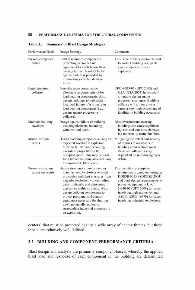
88 PERFORMANCE CRITERIA FOR STRUCTURAL COMPONENTS
Table 3.1 Summary of Blast Design Strategies
Performance Goals Design Strategy Comments
Prevent componentfailure
Limit response of componentsprotecting personnel andequipment to levels below thosecausing failure. A safety factoragainst failure is provided byminimizing expected damagelevels.
This is the primary approach usedto protect building occupantsagainst injuries from anexplosion.
Limit structuralcollapse
Prescribe more conservativeallowable response criteria forload-bearing components. Also,design buildings to withstandlocalized failure of a primary orload-bearing component (i.e.,design against progressivecollapse).
UFC 4-023-03 (UFC 2005) andGSA (GSA 2003) have specificriteria to design againstprogressive collapse. Buildingcollapse will almost alwayscause a very high percentage offatalities to building occupants.
Maintain buildingenvelope
Design against failure of buildingcladding elements, includingwindows and doors.
Blast overpressure enteringbuildings can cause significaninjuries and extensive damage,but not usually many fatalities.
Minimize flyindebris
Design cladding components using anexpected worst-case explosivethreat to fail without becominghazardous projectiles to theoccupied space. This may be usedfor a limited building area receivingthe worst-case blast loads.
Mitigating the extent and severityof injuries to occupants inbuilding areas without overallstructure collapse is verydependent on minimizing flyindebris.
Prevent cascadingexplosion events
Design structures around stored ormanufactured explosives to resistprojectiles and blast pressures froma nearby explosion without failingcatastrophically and detonatingexplosives within structure. Also,design building components toprotect personnel and controlequipment necessary for shuttingdown potentially explosivesurrounding industrial processes inan explosion.
This includes proscriptiverequirements based on testing inDDESB 6055.9 (DDESB 2004)and blast design requirements toprotect equipment in UFC3-340-02 (UFC 2008) for casesinvolving high explosives andASCE (ASCE 1997b) for casesinvolving industrial explosions.
centers) that must be protected against a wide array of enemy threats, but thesethreats are relatively well defined
3.2 BUILDING AND COMPONENT PERFORMANCE CRITERIA
Blast design and analysis are primarily component-based, whereby the appliedblast load and response of each component in the building are determined

BUILDING AND COMPONENT PERFORMANCE CRITERIA 89
Table 3.2 Summary of Blast Design Areas
Design Area Performance Goals Comments
Explosive safety Protect personnelProtect equipment,supplies, and storedexplosives Preventcascading explosiveevents
Design against accidental explosion wherethe amount and location of potentialexplosives are relatively well quantifiedAll inhabited areas are designed toprevent injuries. This type of blast designgenerally has the most designconservatism.
Hardened militarystructures
Preservemission-criticalfunctions
Buildings designed to resist attacks fromspecifie weapons with a near-miss ordirect hit such that given operations canstill be performed.
Antiterrorism Prevent mass casualtiesMinimize flyindebris Limitstructural collapse
There are uncertainties in the amount andlocation of potential explosions causedby terrorists. The usual intent is to buildin a given amount of blast resistanceusing a level of protection against a givendefine threat. A maximum standoffdistance to the protected building isestablished with barriers and inspectionsfor explosives.
Process safety Protect personnelPrevent cascadingevents Minimizefinancia losses
Explosive events can be modeled relativelywell, but initial conditions of the accidentcausing explosion must be assumed.Neutral risk philosophy is employed suchthat people inside buildings should havethe same protection as those outsidebuildings. Ability to shut downoperations is often important to preventcascading events.
individually. However, performance goals are usually set in terms of life safety,functionality, and reusability for the entire building. Therefore, damage or re-sponse levels for individual building components must be established to achievethe overall building performance goal. A framework for this process has been de-veloped by the American Society of Civil Engineers (ASCE, forthcoming) basedon a similar approach developed by the U.S. Army Corps of Engineers, Protec-tive Design Center (PDC) (Protective Design Center 2008b). In this approach, abuilding Level of Protection is selected based on desired performance goals, asshown in Table 3.3. Table 3.4 is then used to determine the associated damagelevels for each type of component in the building. Therefore, this approach de-termines component damage levels that are consistent with an overall buildingperformance goal. It can also be used to assess the Level of Protection providedby an existing building, based on calculated component damage levels.
Table 3.4 refers to three types of components: primary, secondary, andnonstructural. Primary components are members whose loss would affect a
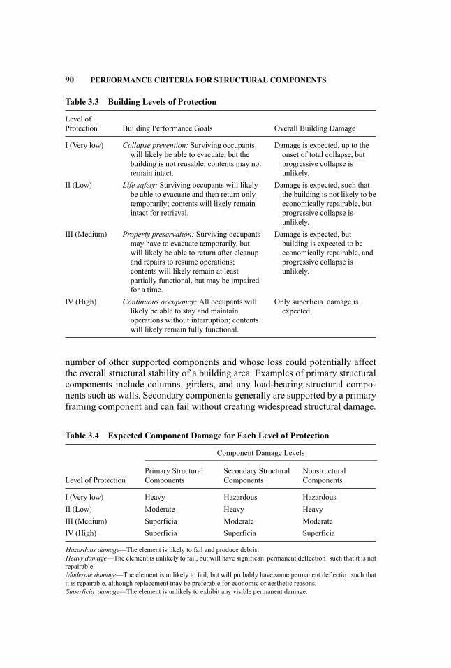
90 PERFORMANCE CRITERIA FOR STRUCTURAL COMPONENTS
Table 3.3 Building Levels of Protection
Level ofProtection Building Performance Goals Overall Building Damage
I (Very low) Collapse prevention: Surviving occupantswill likely be able to evacuate, but thebuilding is not reusable; contents may notremain intact.
Damage is expected, up to theonset of total collapse, butprogressive collapse isunlikely.
II (Low) Life safety: Surviving occupants will likelybe able to evacuate and then return onlytemporarily; contents will likely remainintact for retrieval.
Damage is expected, such thatthe building is not likely to beeconomically repairable, butprogressive collapse isunlikely.
III (Medium) Property preservation: Surviving occupantsmay have to evacuate temporarily, butwill likely be able to return after cleanupand repairs to resume operations;contents will likely remain at leastpartially functional, but may be impairedfor a time.
Damage is expected, butbuilding is expected to beeconomically repairable, andprogressive collapse isunlikely.
IV (High) Continuous occupancy: All occupants willlikely be able to stay and maintainoperations without interruption; contentswill likely remain fully functional.
Only superficia damage isexpected.
number of other supported components and whose loss could potentially affectthe overall structural stability of a building area. Examples of primary structuralcomponents include columns, girders, and any load-bearing structural compo-nents such as walls. Secondary components generally are supported by a primaryframing component and can fail without creating widespread structural damage.
Table 3.4 Expected Component Damage for Each Level of Protection
Component Damage Levels
Level of ProtectionPrimary StructuralComponents
Secondary StructuralComponents
NonstructuralComponents
I (Very low) Heavy Hazardous HazardousII (Low) Moderate Heavy HeavyIII (Medium) Superficia Moderate ModerateIV (High) Superficia Superficia Superficia
Hazardous damage—The element is likely to fail and produce debris.Heavy damage—The element is unlikely to fail, but will have significan permanent deflection such that it is notrepairable.Moderate damage—The element is unlikely to fail, but will probably have some permanent deflectio such thatit is repairable, although replacement may be preferable for economic or aesthetic reasons.Superficia damage—The element is unlikely to exhibit any visible permanent damage.

RESPONSE PARAMETERS 91
Examples of secondary structural components include non-load-bearing infilmasonry walls, metal panels, and secondary steel framing members such asstuds, girts, purlins, and joists. Nonstructural components include interiornon-load-bearing walls, and architectural items attached to building structuralcomponents.
Nonstructural components are not usually designed specificall against designblast loads. In general, their performance has received very little attention, sincetesting and research for blast-resistant design has focused on structural compo-nents. However, when appropriate, depending on the level of protection, thesenonstructural components can be attached to structural members with strength-ened connections in manner similar to that used in earthquake-resistant design.
3.3 RESPONSE PARAMETERS
Component blast damage levels, such as those in Table 3.4, have been correlatedto the maximum dynamic deflectio of the component with two nondimensionalparameters: the ductility ratio (µ) and support rotation (θ). The reasons for bas-ing the correlations on these simplifie parameters are discussed in this section,as well as the limitations of this approach. The support rotation is define inFigure 3.1:
θ = tan−1(2xmLmin
)
where: Lmin = is the shortest distance from a point of maximum deflectio to asupport
It is based on the shortest distance from a support to the point of maximum com-ponent deflectio (Lmin), where the point of maximum deflectio is determinedfrom yield line theory. Lmin is equal to one-half the span length of one-way span-ning components, except for cantilevers where Lmin is the whole span length.The yield line pattern for two-way spanning components can be determined fromcharts in UFC 3-340-02 (Unifie Facilities Criteria Program 2008), which is anupdate of TM 5-1300 (DOANAF 1990).
The ductility ratio is define as the ratio of the maximum component deflection to the component yield deflection as shown in Equation 3.1. The yield
θ = Support Rotation
Lmin
L
XM
Figure 3.1 Support Rotation Angle
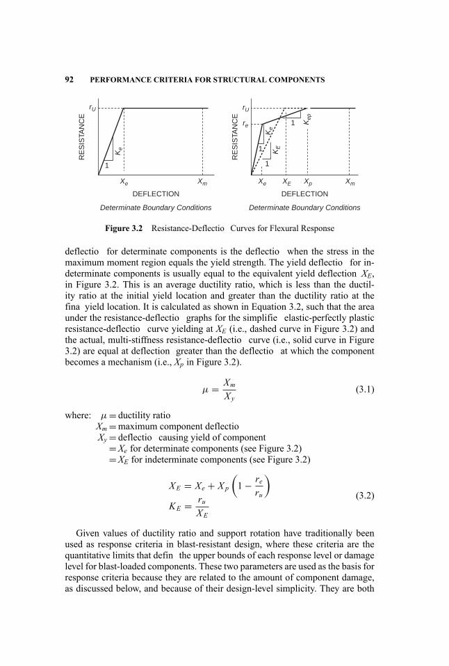
92 PERFORMANCE CRITERIA FOR STRUCTURAL COMPONENTS
DEFLECTION
RE
SIS
TAN
CE
1
Determinate Boundary Conditions
rU
Xe Xm
Ke
DEFLECTION
RE
SIS
TAN
CE
1
1
1
Determinate Boundary Conditions
rU
re
Xe XE XmXp
Ke
KE
Kep
Figure 3.2 Resistance-Deflectio Curves for Flexural Response
deflectio for determinate components is the deflectio when the stress in themaximum moment region equals the yield strength. The yield deflectio for in-determinate components is usually equal to the equivalent yield deflection XE,in Figure 3.2. This is an average ductility ratio, which is less than the ductil-ity ratio at the initial yield location and greater than the ductility ratio at thefina yield location. It is calculated as shown in Equation 3.2, such that the areaunder the resistance-deflectio graphs for the simplifie elastic-perfectly plasticresistance-deflectio curve yielding at XE (i.e., dashed curve in Figure 3.2) andthe actual, multi-stiffness resistance-deflectio curve (i.e., solid curve in Figure3.2) are equal at deflection greater than the deflectio at which the componentbecomes a mechanism (i.e., Xp in Figure 3.2).
µ = XmXy
(3.1)
where: µ = ductility ratioXm =maximum component deflectioXy = deflectio causing yield of component
=Xe for determinate components (see Figure 3.2)=XE for indeterminate components (see Figure 3.2)
XE = Xe + X p
(1− re
ru
)
KE = ruXE
(3.2)
Given values of ductility ratio and support rotation have traditionally beenused as response criteria in blast-resistant design, where these criteria are thequantitative limits that defin the upper bounds of each response level or damagelevel for blast-loaded components. These two parameters are used as the basis forresponse criteria because they are related to the amount of component damage,as discussed below, and because of their design-level simplicity. They are both
RESPONSE PARAMETERS 93
based on the maximum dynamic component deflection which is relatively easyto measure in component blast tests and to calculate with simplifie dynamicanalysis methods used for blast design.
Damage occurs in blast-loaded components as plastic strains approach thematerial failure strain at some location in the component. The ductility ratio isan approximate measure of component plastic strain based on the assumptionthat the curvature in the maximum moment regions increases proportionallywith deflectio after yielding, and plane cross sections remain plane. In thiscase, the ductility ratio is a measure of the ratio of the total strain to the yieldstrain in the maximum fibers This approach is applicable to cases where thestrains causing the component damage occur at the same location where initialyielding occurs, such as the extreme fibe of the maximum moment region ofa steel beam. In reinforced concrete, on the other hand, damage is primarilycontrolled by compression strains as they approach a given limit value (i.e., theconcrete crushing strain), whereas initial yielding occurs in the tension steelat a deflectio that usually causes relatively low compression strains in themaximum moment region. Therefore, the ductility ratio does not correlate wellwith fl xural damage to reinforced concrete members. Also, very ductile steelmembers typically develop tension membrane response at high ductility levels,which can causes high strains and failure around the connections, rather than atmidspan, where initial yielding occurs.
The support rotation correlates better to component blast damage than theductility ratio in these cases. In the case of reinforced concrete and masonry com-ponents, the support rotation is related to the cross section rotation at maximummoment regions, and therefore to the compression face strain, which primarilycauses damage and failure to underreinforced components. This is the case whenthe component responds as a ductile mechanism after yielding of the reinforcingsteel. Very little damage occurs prior to yielding of the reinforcing steel.
In the case of tension membrane response, the support rotation increases pro-portionally with the maximum deflection-to-spa ratio and therefore increaseswith the amount of tension membrane response. Support rotation limits help en-sure that the amount of tension membrane force in a ductile component thatcan undergo large deflection is limited to values that do not allow connectionfailures. Large deflection of primary components can also cause failures at con-nections to supported components. Many blast tests and fiel investigations ataccidental explosion sites have shown that steel components connected to theirsupports with screws, bolts, and welds typically fail at the connection, ratherthan at the points of maximum strain in the component (i.e., yield locations).Therefore, ductile steel components typically have separate response criteria interms of ductility ratio, to limit plastic strains at the maximum moment region,and in terms of support rotation, to limit strains from tension membrane responsenear connections or other critical areas (i.e., utility cutouts in well-attached metalstuds).
The ductility ratio is usually most useful for determining damage levels withlow ductility ratios in the range of 1.0 to approximately 3.0. This applies to low

94 PERFORMANCE CRITERIA FOR STRUCTURAL COMPONENTS
damage levels for ductile components and low to high damage levels of relativelybrittle components, such as wood components. Damage from brittle, nonfl xuralresponse modes, such as shear, buckling, or connection failure, can also be cor-related to the ductility ratio if the yield deflection Xy, in these cases equals themaximum component deflectio causing a critical shear, buckling, or connectionstrain in the component and these strains increase proportionally with increasedcomponent deflection
Limit support rotations and ductility ratios that establish component damagelevels generally cannot be derived from theoretical considerations alone. Theseparameters are simplifie for practical reasons and failure modes are complexand influence significantl from actions, such as combined bending, shear, andaxial load, which are difficul if not impossible to quantify and characterize uni-versally. Also, applicable damage levels typically have qualitative, rather thanquantitative, descriptions. Therefore, limit values for these parameters are basedprimarily on empirical correlations between observed damage levels to compo-nents from blast tests and corresponding values of support rotations and ductilityratios calculated from the component’s measured maximum dynamic deflectionThis is discussed more in the next section.
A limitation in this approach is that the support rotation and ductility ratioterms do not capture all the parameters that are actually related to the observedcomponent blast damage. For example, an analysis of data from fiftee one-way-spanning reinforced masonry walls tested in a shock tube showed that therelationship between the measured support rotations and the observed damagelevels was strongly dependent on the wall reinforcement factor, which comparesthe reinforcing steel ratio to the balanced steel ratio, as well as to the supportrotation (Oswald and Nebuda 2006). The test walls with a low reinforcementfactor sustained significantl less damage at the same support rotation than wallswith a higher factor. Also, a statistical study of several hundred static reinforcedconcrete beam and slab tests showed that the support rotation at failure was notconstant, as generally assumed for blast design, but was a function of severalparameters, including the reinforcing steel ratio, the shear span to depth ratio,and the ratio of the steel reinforcement yield strength to concrete compressionstrength (Panagiotakos and Fardis 2001). Therefore, if two concrete panels withdifferent spans, thicknesses, and reinforcement ratios are both subject to blastloads causing the same given support rotation (e.g., 2 degrees), it is possible thatthey will not have the same observed damage level. A similar situation is possiblefor other component types. Fortunately, this is alleviated to some extent by thequalitative nature of damage levels, which encompass relatively broad ranges ofdamage.
In spite of the limitations of the support rotation and ductility ratio asdefinit ve measures of component damage, it is the judgment and experienceof engineers who have developed response criteria relating these parameters tocomponent damage that they are adequate and generally conservative for blastdesign and analysis purposes. More accurate terms that include more prop-erties associated with a component’s blast damage level, and have acceptablesimplicity for design-based methodologies, may be developed in the future.
RESPONSE PARAMETERS AND DAMAGE CORRELATIONS 95
3.4 EMPIRICAL CORRELATIONS BETWEEN RESPONSEPARAMETERS AND COMPONENT DAMAGE
Support rotations and/or ductility ratios that defin the damage levels of blast-loaded components have been established using correlations between these twoparameters calculated from available test data and observed damage levels inthe test components. The amount of available test data varies with componenttype, since blast testing is typically conducted by various government agenciesand organizations to address specifi blast design considerations, and the datainclude varying amounts of measured material properties, blast load information,and response values. Also, there is an almost complete lack of blast test datafor some component types and damage levels. Deflection-controlle static teststhat provide information on component performance at post-yield deflectionare considered for component types with limited available blast test data. Thesestatic data are generally conservative because each strain and deformation levelexists for a sustained period of time, and can therefore result in more damagethan the same strain level that will only exist from a blast load for a few tenthsof a second, or less.
The most comprehensive published study that has correlated blast test datawith component damage levels is part of the Component Explosive Damage As-sessment Workbook (CEDAW) methodology (Protective Design Center 2008a).CEDAW is a fast-running methodology to assess component blast damage basedon pressure-impulse (P-I) diagrams that was developed to be as consistent aspossible with available blast test data. In this study, data were collected fromover 300 blast tests on 10 different component types and used to calculate thesupport rotation and ductility ratio for each test, using single-degree-of-freedom(SDOF) dynamic analyses. Then, this information was used to determine the ro-tations and ductility ratios that bounded each observed damage level for eachcomponent type, using scaled P-I diagrams.
This effort is illustrated in Figure 3.3 and Figure 3.4, which are based ondamage levels define in Table 3.5. Pbar and Ibar in the graphs are the peakpositive phase pressure and impulse, respectively, scaled (i.e., divided) byrelevant component dynamic response parameters to create dimensionless termsthat are directly related to component response. Therefore, components withvery different blast loads and structural properties, but the same Pbar and Ibarvalues, should have the same ductility ratio or support rotation values (i.e.,a strong component with a high blast load and a weaker component with alower blast load that both have response with the same ductility ratio or supportrotation would have the same Pbar and Ibar values). This should be true in bothblast tests and dynamic response calculations. The Ibar terms for componentresponse in terms of ductility ratio are different from those for componentresponse in terms of support rotation.
Figure 3.3 shows a scaled P-I diagram with curves of scaled blast loadscalculated with SDOF analyses causing ductility ratios (µ) of 1, 3, 6, and 12 fora corrugated steel panel. These curves are plotted with data points of scaled blastloads causing damage levels ranging from Superficia to Hazardous Failure to

96 PERFORMANCE CRITERIA FOR STRUCTURAL COMPONENTS
100
10
10 100
Pba
r
Ibar 1
1
10.1
0.1
µ = 12
µ = 6µ = 3
µ = 1
SuperficialModerate
Heavy
Sup. DataMod. DataHeavy Data
Haz. Failure
H.Fail Data
Figure 3.3 Scaled P-I Curves in Terms of Ductility Ratio vs. Scaled Data for FlexuralResponse of Corrugated Steel Panels
corrugated steel panels in blast tests. Figure 3.4 is a similar scaled P-I diagramwith curves of scaled blast loads calculated with SDOF analyses causing supportrotations (θ) of 3, 6, and 10 degrees plotted against the same data that arescaled by Pbar and Ibar terms based on component support rotation. In bothof these figures the curves with the lowest support rotation or ductility ratiocorrespond to the lowest damage level (i.e., Superficial) and curves with highersupport rotations and ductility ratios correspond to higher damage levels up toHazardous Failure.
Figure 3.3 and Figure 3.4 were used to determine that the ductility ra-tios and support rotations shown on the figure bounded each of the damage
θ = 3
θ = 10
θ = 610
100
Pba
r
Ibar 2
1
1
0.10.010.1
ModerateHeavy
Mod. DataHeavy Data
Haz. Failure
H.Fail DataBlowout Data
Figure 3.4 Scaled P-I Curves in Terms of Support Rotation (Degrees) vs. Scaled Datafor Flexural Response of Corrugated Steel Panels
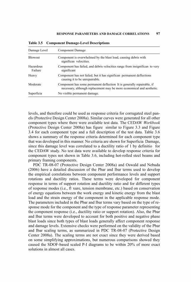
RESPONSE PARAMETERS AND DAMAGE CORRELATIONS 97
Table 3.5 Component Damage-Level Descriptions
Damage Level Component Damage
Blowout Component is overwhelmed by the blast load, causing debris withsignifican velocities.
HazardousFailure
Component has failed, and debris velocities range from insignifican to verysignificant
Heavy Component has not failed, but it has significan permanent deflectionscausing it to be unrepairable.
Moderate Component has some permanent deflection It is generally repairable, ifnecessary, although replacement may be more economical and aesthetic.
Superficia No visible permanent damage.
levels, and therefore could be used as response criteria for corrugated steel pan-els (Protective Design Center 2008a). Similar curves were generated for all othercomponent types where there were available test data. The CEDAW Workbook(Protective Design Center 2008a) has figure similar to Figure 3.3 and Figure3.4 for each component type and a full description of the test data. Table 3.6shows a summary of the response criteria determined for each component typethat was developed in this manner. No criteria are shown for Superficia Damage,since this damage level was correlated to a ductility ratio of 1 by definitio forthe CEDAW study. No test data were available to develop response criteria forcomponent types not shown in Table 3.6, including hot-rolled steel beams andprimary framing components.
PDC TR-08-07 (Protective Design Center 2008a) and Oswald and Nebuda(2006) have a detailed discussion of the Pbar and Ibar terms used to developthe empirical correlations between component performance levels and supportrotations and ductility ratios. These terms were developed for componentresponse in terms of support rotation and ductility ratio and for different typesof response modes (i.e., fl xure, tension membrane, etc.) based on conservationof energy equations between the work energy and kinetic energy from the blastload and the strain energy of the component in the applicable response mode.The parameters included in the Pbar and Ibar terms vary based on the type of re-sponse mode for the component and the type of response parameter representingthe component response (i.e., ductility ratio or support rotation). Also, the Pbarand Ibar terms were developed to account for both positive and negative phaseblast loads since both types of blast loads generally affect component responseand damage levels. Extensive checks were performed on the validity of the Pbarand Ibar scaling terms, as summarized in PDC TR-08-07 (Protective DesignCenter 2008a). The scaling terms are not exact since they were derived basedon some simplifying approximations, but numerous comparisons showed theycaused the SDOF-based scaled P-I diagrams to be within 20% of more exactsolutions in almost all cases.
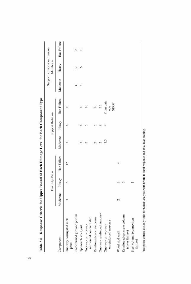
Table3.6
ResponseCriteriaforUpperBound
ofEachDam
ageLevelforEachCom
ponentType
Ductility
Ratio
SupportR
otation
SupportR
otationw/Tension
Mem
brane
Com
ponent
Moderate
Heavy
Haz
Failure
Moderate
Heavy
Haz
Failure
Moderate
Heavy
Haz
Failure
One-way
corrugated
metal
panel
36
123
610
Cold-formed
girtandpurlins
412
20Open-web
steeljoist
36
103
610
One-way
ortwo-way
reinforced
concreteslab
25
10
Reinforcedconcretebeam
25
10One-way
reinforced
masonry
28
15One-way
ortwo-way
unreinforced
masonry
11.5
4From
data
w/o
SDOF
Woodstud
wall
23
4Reinforcedconcretecolumn
(shearfailure)
6
Steelcolum
n(connection
failure)
1
1 Responsecriteria
areonlyvalid
forS
DOFanalyseswith
brittleflxuralresponseandaxialloadarching.
98
RESPONSE CRITERIA DEVELOPMENT 99
3.5 RESPONSE CRITERIA DEVELOPMENT
The information in Table 3.6 represents the most extensive and formalized useof blast test data to develop response criteria. This information was an importantpart of the development of several of the current blast response criteria, However,it was not the only consideration. Each organization that has developed responsecriteria definin given performance levels considers a range of factors, such asthe exact definition of its performance levels relative to the available data, howto address component types where the data are inadequate, whether to discountsome data or data sets as not applicable, and the level of conservatism to beincluded in the response criteria. There is very limited published information onthese considerations or on the compilations of the data that were considered.
Table 3.7 shows a summary of response criteria that have been developed foreach area of blast design. Ideally, there would be one general set of response lim-its on component response applicable for all the performance levels and designstrategies in Table 3.1. There is strong movement in this direction, but currentlythere are separate sets of response limits associated with performance levels es-tablished by the different organizations associated with each area of blast design.These differences are due in part to the fact that these organizations have differ-ent missions, design objectives, and types of explosive threats.
The following subsections provide some detail on the criteria in Table 3.7. Inall cases the response criteria are stated in terms of either ductility ratio, supportrotation, or both terms, as discussed in Section 3.2. In cases where response cri-teria for both terms are provided, the overall component damage level or perfor-mance level is controlled by the response criterion that causes more severe dam-age or lower performance. In addition to the response criteria discussed below,the engineer should also always consider any design-case-specifi requirementson component deflectio and limitations of response criteria, as discussed in Sec-tion 3.6. It should also be noted that all the response limits stated in this documentmay be updated in the future. Historically, response criteria have been updatedas more information on component response to blast loads has become availableand as new component and material types are used for blast-resistant design.
3.5.1 Explosive Safety Criteria
Blast-resistant design criteria are included in UFC 3-340-02 (Unifie FacilitiesCriteria Program 2008), which has been developed by the explosive safety designcommunity under direction of the U.S. Department of Defense Explosive SafetyBoard (DDESB). Explosive safety refers to safe design and operation of manu-facturing and storage areas for high explosives that can accidently explode. Thisprimarily includes military and military contractor facilities with explosives, butit also includes industries such as fir works and commercial explosives manu-facturers.
Most blast-resistant design prior to 1990 was for explosive safety and criti-cal military structures, and the majority of the initial blast testing of structural
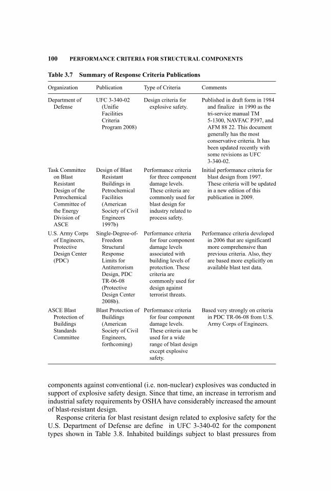
100 PERFORMANCE CRITERIA FOR STRUCTURAL COMPONENTS
Table 3.7 Summary of Response Criteria Publications
Organization Publication Type of Criteria Comments
Department ofDefense
UFC 3-340-02(UnifieFacilitiesCriteriaProgram 2008)
Design criteria forexplosive safety.
Published in draft form in 1984and finalize in 1990 as thetri-service manual TM5-1300, NAVFAC P397, andAFM 88 22. This documentgenerally has the mostconservative criteria. It hasbeen updated recently withsome revisions as UFC3-340-02.
Task Committeeon BlastResistantDesign of thePetrochemicalCommittee ofthe EnergyDivision ofASCE
Design of BlastResistantBuildings inPetrochemicalFacilities(AmericanSociety of CivilEngineers1997b)
Performance criteriafor three componentdamage levels.These criteria arecommonly used forblast design forindustry related toprocess safety.
Initial performance criteria forblast design from 1997.These criteria will be updatedin a new edition of thispublication in 2009.
U.S. Army Corpsof Engineers,ProtectiveDesign Center(PDC)
Single-Degree-of-FreedomStructuralResponseLimits forAntiterrorismDesign, PDCTR-06-08(ProtectiveDesign Center2008b).
Performance criteriafor four componentdamage levelsassociated withbuilding levels ofprotection. Thesecriteria arecommonly used fordesign againstterrorist threats.
Performance criteria developedin 2006 that are significantlmore comprehensive thanprevious criteria. Also, theyare based more explicitly onavailable blast test data.
ASCE BlastProtection ofBuildingsStandardsCommittee
Blast Protection ofBuildings(AmericanSociety of CivilEngineers,forthcoming)
Performance criteriafor four componentdamage levels.These criteria can beused for a widerange of blast designexcept explosivesafety.
Based very strongly on criteriain PDC TR-06-08 from U.S.Army Corps of Engineers.
components against conventional (i.e. non-nuclear) explosives was conducted insupport of explosive safety design. Since that time, an increase in terrorism andindustrial safety requirements by OSHA have considerably increased the amountof blast-resistant design.
Response criteria for blast resistant design related to explosive safety for theU.S. Department of Defense are define in UFC 3-340-02 for the componenttypes shown in Table 3.8. Inhabited buildings subject to blast pressures from
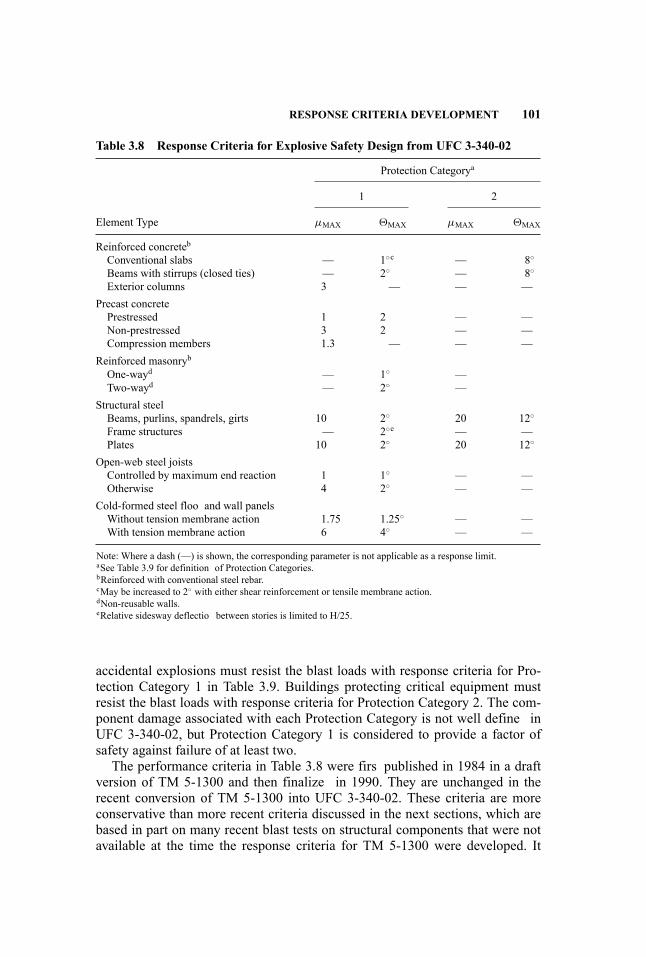
RESPONSE CRITERIA DEVELOPMENT 101
Table 3.8 Response Criteria for Explosive Safety Design from UFC 3-340-02
Protection Categorya
1 2
Element Type µMAX �MAX µMAX �MAX
Reinforced concretebConventional slabs — 1◦c — 8◦
Beams with stirrups (closed ties) — 2◦ — 8◦
Exterior columns 3 — — —Precast concretePrestressed 1 2 — —Non-prestressed 3 2 — —Compression members 1.3 — — —
Reinforced masonrybOne-wayd — 1◦ —Two-wayd — 2◦ —
Structural steelBeams, purlins, spandrels, girts 10 2◦ 20 12◦
Frame structures — 2◦e — —Plates 10 2◦ 20 12◦
Open-web steel joistsControlled by maximum end reaction 1 1◦ — —Otherwise 4 2◦ — —
Cold-formed steel floo and wall panelsWithout tension membrane action 1.75 1.25◦ — —With tension membrane action 6 4◦ — —
Note: Where a dash (—) is shown, the corresponding parameter is not applicable as a response limit.aSee Table 3.9 for definition of Protection Categories.bReinforced with conventional steel rebar.cMay be increased to 2◦ with either shear reinforcement or tensile membrane action.dNon-reusable walls.eRelative sidesway deflectio between stories is limited to H/25.
accidental explosions must resist the blast loads with response criteria for Pro-tection Category 1 in Table 3.9. Buildings protecting critical equipment mustresist the blast loads with response criteria for Protection Category 2. The com-ponent damage associated with each Protection Category is not well define inUFC 3-340-02, but Protection Category 1 is considered to provide a factor ofsafety against failure of at least two.
The performance criteria in Table 3.8 were firs published in 1984 in a draftversion of TM 5-1300 and then finalize in 1990. They are unchanged in therecent conversion of TM 5-1300 into UFC 3-340-02. These criteria are moreconservative than more recent criteria discussed in the next sections, which arebased in part on many recent blast tests on structural components that were notavailable at the time the response criteria for TM 5-1300 were developed. It
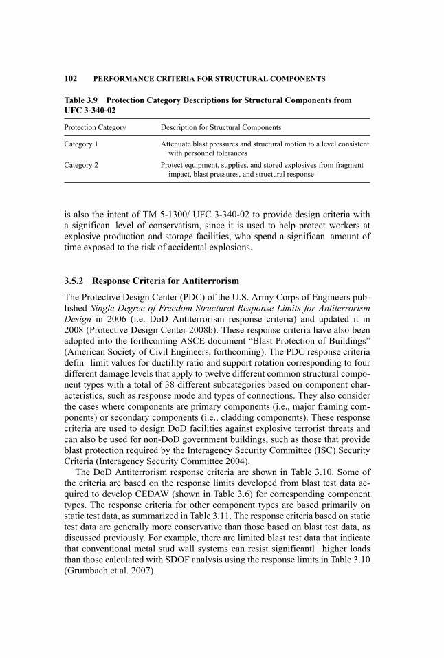
102 PERFORMANCE CRITERIA FOR STRUCTURAL COMPONENTS
Table 3.9 Protection Category Descriptions for Structural Components fromUFC 3-340-02
Protection Category Description for Structural Components
Category 1 Attenuate blast pressures and structural motion to a level consistentwith personnel tolerances
Category 2 Protect equipment, supplies, and stored explosives from fragmentimpact, blast pressures, and structural response
is also the intent of TM 5-1300/ UFC 3-340-02 to provide design criteria witha significan level of conservatism, since it is used to help protect workers atexplosive production and storage facilities, who spend a significan amount oftime exposed to the risk of accidental explosions.
3.5.2 Response Criteria for Antiterrorism
The Protective Design Center (PDC) of the U.S. Army Corps of Engineers pub-lished Single-Degree-of-Freedom Structural Response Limits for AntiterrorismDesign in 2006 (i.e. DoD Antiterrorism response criteria) and updated it in2008 (Protective Design Center 2008b). These response criteria have also beenadopted into the forthcoming ASCE document “Blast Protection of Buildings”(American Society of Civil Engineers, forthcoming). The PDC response criteriadefin limit values for ductility ratio and support rotation corresponding to fourdifferent damage levels that apply to twelve different common structural compo-nent types with a total of 38 different subcategories based on component char-acteristics, such as response mode and types of connections. They also considerthe cases where components are primary components (i.e., major framing com-ponents) or secondary components (i.e., cladding components). These responsecriteria are used to design DoD facilities against explosive terrorist threats andcan also be used for non-DoD government buildings, such as those that provideblast protection required by the Interagency Security Committee (ISC) SecurityCriteria (Interagency Security Committee 2004).
The DoD Antiterrorism response criteria are shown in Table 3.10. Some ofthe criteria are based on the response limits developed from blast test data ac-quired to develop CEDAW (shown in Table 3.6) for corresponding componenttypes. The response criteria for other component types are based primarily onstatic test data, as summarized in Table 3.11. The response criteria based on statictest data are generally more conservative than those based on blast test data, asdiscussed previously. For example, there are limited blast test data that indicatethat conventional metal stud wall systems can resist significantl higher loadsthan those calculated with SDOF analysis using the response limits in Table 3.10(Grumbach et al. 2007).
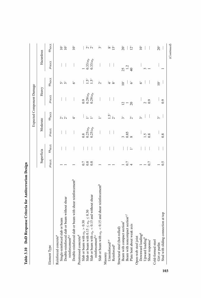
Table3.10
DoD
ResponseCriteriaforAntiterrorismDesign
Expected
Com
ponentDam
age
Superficia
Moderate
Heavy
Hazardous
Elem
entType
µMAX
�MAX
µMAX
�MAX
µMAX
�MAX
µMAX
�MAX
Reinforcedconcretea
Single-reinforcedslab
orbeam
1—
—2◦
—5◦
—10
◦
Double-reinforced
slab
orbeam
withoutshear
reinforcem
entb,
c1
——
2◦—
5◦—
10◦
Double-reinforced
slab
orbeam
with
shearreinforcementb
1—
—4◦
—6◦
—10
◦
Prestressed
concreted
Slab
orbeam
with
ωp>0.30
0.7
—0.8
—0.9
—1
—Slab
orbeam
with
0.15
≤ωp≤0.30
0.8
—0.25/ω
p1◦
0.29/ω
p1.5◦
0.33/ω
p2◦
Slab
orbeam
with
ωp<0.15
andwithoutshear
reinforcem
entb,
c0.8
—0.25/ω
p1◦
0.29/ω
p1.5◦
0.33/ω
p2◦
Slab
orbeam
with
ωp<0.15
andshearreinforcementb
1—
—1◦
—2◦
—3◦
Masonry
Unreinforcedc
,e1
——
1.5◦
—4◦
—8◦
Reinforceda
1—
—2◦
—8◦
—15
◦
Structuralsteel(hot-rolled)
Beamwith
compactsectionf
1—
33◦
1210
◦25
20◦
Beamwith
noncom
pactsectionc
,f0.7
—0.85
1—
1.2
—Platebentaboutw
eakaxis
41◦
82◦
206◦
4012
◦
Open-web
steeljoist
Dow
nwardloadingg
1—
—3◦
—6◦
—10
◦
Upw
ardloadingh
1—
1.5
—2
—3
—Shearresponsei
0.7
—0.8
—0.9
—1
—Cold-formed
steel
Girt
orpurlin
1—
—3◦
—10
◦—
20◦
Stud
with
slidingconnectionattop
0.5
—0.8
—0.9
—1
—
(Continued)
103
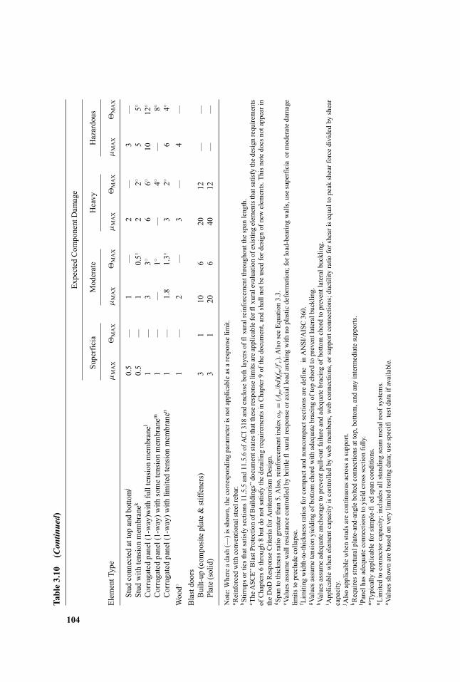
Table3.10
(Continued)
Expected
Com
ponentDam
age
Superficia
Moderate
Heavy
Hazardous
Elem
entType
µMAX
�MAX
µMAX
�MAX
µMAX
�MAX
µMAX
�MAX
Stud
connectedattopandbottomj
0.5
—1
—2
—3
—Stud
with
tensionmem
branek
0.5
—1
0.5◦
22◦
55◦
Corrugatedpanel(1-way)with
fulltensionmem
branel
1—
33◦
66◦
1012
◦
Corrugatedpanel(1-way)w
ithsometensionmem
branem
1—
—1◦
—4◦
—8◦
Corrugatedpanel(1-way)w
ithlim
itedtensionmem
branen
1—
1.8
1.3◦
32◦
64◦
Wood◦
1—
2—
3—
4—
Blastdoors
Built-up
(com
positeplate&stiffeners)
31
106
2012
——
Plate(solid)
31
206
4012
——
Note:Whereadash
(—)isshown,thecorrespondingparameterisnotapplicableasaresponselim
it.a Reinforcedwith
conventionalsteelrebar.
b Stirrups
ortiesthatsatisfysections
11.5.5and11.5.6ofACI318
andenclosebothlayersofflxuralreinforcementthroughoutthe
span
length.
c The
ASC
E”BlastProtectionofBuildings”documentstatesthattheseresponselim
itsareapplicableforflx
uralevaluationofexistingelem
entsthatsatisfythedesign
requirements
ofChapters6
through8butdonotsatisfythedetailing
requirementsinChapter9ofthedocument,andshallnotbe
used
fordesignofnewelem
ents.Thisn
otedoesnotappearin
theDoD
ResponseCriteriaforA
ntiterrorismDesign.
d Spantothicknessratiogreaterthan5.Also,reinforcem
entindex
ωp
=(Aps/bd)(f p
s/f′ c).AlsoseeEquation3.3.
e Valuesassum
ewallresistancecontrolledby
brittleflxuralresponseoraxialloadarchingwith
noplastic
deformation;forload-bearingwalls,usesuperficia
ormoderatedamage
limits
topreclude
collapse.
f Limiting
width-to-thicknessratiosforcompactandnoncom
pactsections
aredefine
inANSI/AISC360.
g Valuesassum
etensionyielding
ofbottomchordwith
adequatebracingoftopchordtopreventlateralbuckling.
h Valuesassum
eadequateanchoragetopreventpull-outfailureandadequatebracingofbottomchordtopreventlateralbuckling.
i Applicablewhenelem
entcapacity
iscontrolledby
web
mem
bers,w
ebconnections,orsupportconnections;ductility
ratio
forshearisequaltopeak
shearforce
dividedby
shear
capacity.
j Alsoapplicablewhenstudsarecontinuous
acrossasupport.
k Requiresstructuralplate-and-angleboltedconnections
attop,bottom,and
anyintermediatesupports.
l Panelhasadequateconnections
toyieldcrosssectionfully.
mTypically
applicableforsimple-fied
span
conditions.
n Limitedtoconnectorcapacity;includesallstanding
seam
metalroofsystem
s.o Valuesshownarebasedon
verylim
itedtestingdata;usespecifi
testdataifavailable.
104
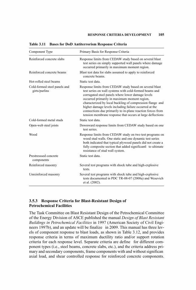
RESPONSE CRITERIA DEVELOPMENT 105
Table 3.11 Bases for DoD Antiterrorism Response Criteria
Component Type Primary Basis for Response Criteria
Reinforced concrete slabs Response limits from CEDAW study based on several blasttest series on simply supported wall panels where damageoccurred primarily in maximum moment region.
Reinforced concrete beams Blast test data for slabs assumed to apply to reinforcedconcrete beams.
Hot-rolled steel beams Static test data.Cold-formed steel panels andgirts/purlins
Response limits from CEDAW study based on several blasttest series on wall systems with cold-formed beams andcorrugated steel panels where lower damage levelsoccurred primarily in maximum moment region,characterized by local buckling of compression flange andhigher damage levels including failure occurred at theconnections due primarily to in-plane reaction forces fromtension membrane response that occurs at large deflections
Cold-formed metal studs Static test data.Open-web steel joists Downward response limits from CEDAW study based on one
test series.Wood Response limits from CEDAW study on two test programs on
wood stud walls. One static and one dynamic test seriesboth indicated that typical plywood panels did not create afully composite section that added significantl to ultimateresistance of stud wall system.
Prestresssed concretecomponents
Static test data.
Reinforced masonry Several test programs with shock tube and high-explosivetests.
Unreinforced masonry Several test programs with shock tube and high-explosivetests documented in PDC TR-08-07 (2008a) and Wesevichet al. (2002).
3.5.3 Response Criteria for Blast-Resistant Design ofPetrochemical Facilities
The Task Committee on Blast Resistant Design of the Petrochemical Committeeof the Energy Division of ASCE published the manual Design of Blast ResistantBuildings in Petrochemical Facilities in 1997 (American Society of Civil Engi-neers 1997b), and an update will be finalize in 2009. This manual has three lev-els of component response to blast loads, as shown in Table 3.12, and providesresponse criteria in terms of maximum ductility ratio and/or support rotationcriteria for each response level. Separate criteria are define for different com-ponent types (i.e., steel beams, concrete slabs, etc.), and the criteria address pri-mary and secondary components, frame components with and without significanaxial load, and shear controlled response for reinforced concrete components.
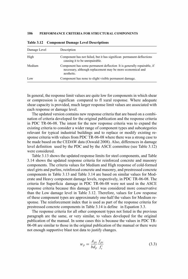
106 PERFORMANCE CRITERIA FOR STRUCTURAL COMPONENTS
Table 3.12 Component Damage Level Descriptions
Damage Level Description
High Component has not failed, but it has significan permanent deflectionscausing it to be unrepairable.
Medium Component has some permanent deflection It is generally repairable, ifnecessary, although replacement may be more economical andaesthetic.
Low Component has none to slight visible permanent damage.
In general, the response limit values are quite low for components in which shearor compression is significan compared to fl xural response. Where adequateshear capacity is provided, much larger response limit values are associated witheach response or damage level.
The updated version contains new response criteria that are based on a combi-nation of criteria developed for the original publication and the response criteriain PDC TR-06-08. The intent for the new response criteria was to expand theexisting criteria to consider a wider range of component types and subcategoriesrelevant for typical industrial buildings and to replace or modify existing re-sponse criteria with values from PDC TR-06-08 where there was a strong case tobe made based on the CEDAW data (Oswald 2008). Also, differences in damagelevel definition used by the PDC and by the ASCE committee (see Table 3.12)were considered.
Table 3.13 shows the updated response limits for steel components, and Table3.14 shows the updated response criteria for reinforced concrete and masonrycomponents. The criteria values for Medium and High response of cold-formedsteel girts and purlins, reinforced concrete and masonry, and prestressed concretecomponents in Table 3.13 and Table 3.14 are based on similar values for Mod-erate and Heavy component damage levels, respectively, in PDC TR-06-08. Thecriteria for Superficia damage in PDC TR-06-08 were not used in the ASCEresponse criteria because this damage level was considered more conservativethan the Low damage level in Table 3.12. Therefore, values for Low responseof these component types are approximately one-half the values for Medium re-sponse. The reinforcement index that is used as part of the response criteria forprestressed concrete components in Table 3.14 is define in Equation 3.3.
The response criteria for all other component types not listed in the previousparagraph are the same, or very similar, to values developed for the originalpublication of the manual. In some cases this is because the values in PDC TR-06-08 are similar to those in the original publication of the manual or there werenot enough supportive blast test data to justify changes.
wp = Apsbdp
f psf ′c
(3.3)
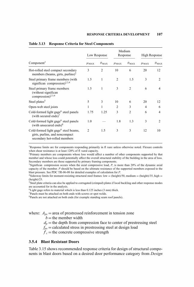
RESPONSE CRITERIA DEVELOPMENT 107
Table 3.13 Response Criteria for Steel Components
Low ResponseMediumResponse High Response
Component1 µMAX θMAX µMAX θMAX µMAX θMAX
Hot-rolled steel compact secondarymembers (beams, girts, purlins)2
3 2 10 6 20 12
Steel primary frame members (withsignifican compression)2,3,4
1.5 1 2 1.5 3 2
Steel primary frame members(without significancompression)2,3,4
1.5 1 3 2 6 4
Steel plates5 5 3 10 6 20 12Open-web steel joists 1 1 2 3 4 6Cold-formed light gage6 steel panels(with secured ends)7
1.75 1.25 3 2 6 4
Cold-formed light gage6 steel panels(with unsecured ends)8
1.0 — 1.8 1.3 3 2
Cold-formed light gage6 steel beams,girts, purlins, and noncompactsecondary hot-rolled members
2 1.5 3 3 12 10
1Response limits are for components responding primarily in fl xure unless otherwise noted. Flexure controlswhen shear resistance is at least 120% of fl xural capacity.2Primary members are components whose loss would affect a number of other components supported by thatmember and whose loss could potentially affect the overall structural stability of the building in the area of loss.Secondary members are those supported by primary framing components.3Significan compression occurs when the axial compressive load, P, is more than 20% of the dynamic axialcapacity of the member. P should be based on the ultimate resistance of the supported members exposed to theblast pressure. See PDC TR-06-08 for detailed examples of calculation for P.4Sidesway limits for moment-resisting structural steel frames: low = (height)/50, medium = (height)/35, high =(height)/25.5Steel plate criteria can also be applied to corrugated (crimped) plates if local buckling and other response modesare accounted for in the analysis.6Light gage refers to material which is less than 0.125 inches (3 mm) thick.7Panels must be attached on both ends with screws or spot welds.8Panels are not attached on both ends (for example standing seam roof panels).
where: Aps = area of prestressed reinforcement in tension zoneb= the member widthdp = the depth from compression face to center of prestressing steelfps = calculated stress in prestressing steel at design loadf′c = the concrete compressive strength
3.5.4 Blast Resistant Doors
Table 3.15 shows recommended response criteria for design of structural compo-nents in blast doors based on a desired door performance category from Design

108 PERFORMANCE CRITERIA FOR STRUCTURAL COMPONENTS
Table 3.14 Response Criteria for Reinforced Concrete (R/C) and Masonry (R/M)Components
Low ResponseMediumResponse High Response
Component1 µMAX θMAX µMAX θMAX µMAX θMAX
R/C beams, slabs, and wall panels (noshear reinforcement)
1 2 5
R/C beams, slabs, and wall panels(compression face steel reinforcementand shear reinforcement in maximummoment areas)
2 4 6
Reinforced masonry 1 2 5R/C walls, slabs, and columns (in fl xureand axial compression load)3
1 22 22
R/C and R/M shear walls & diaphragms 3 3 3R/C and R/M components (shear control,without shear reinforcement)
1.3 1.3 1.3
R/C and R/M components (shear control,with shear reinforcement)
1.6 1.6 1.6
Prestressed concrete (wp ≤ 0.15)4 1 1 2Prestressed concrete (0.15 < wp < 0.3)4 1 0.25/wp 1 0.29/wp 1.5
1Response limits are for components reinforced with conventional rebar or prestressing strands responding pri-marily in fl xure unless otherwise noted.2A support rotation of 4 degrees is allowed for R/C components that have compression face steel reinforcementand shear reinforcement in maximum moment areas.3Applicable when the axial compressive load, P, is more than 20% of the dynamic axial capacity of the member.P should be based on the ultimate resistance of the supported members exposed to the blast pressure. Refer toPDC TR-06-08 for detailed examples of calculation for P.4The reinforcement index, wp, is define in Equation 3.3.
of Blast Resistant Buildings in Petrochemical Facilities (American Society ofCivil Engineers 1997b). Table 3.10 shows similar design information from PDCTR-06-08. Blast doors can be designed using SDOF analyses of door compo-nents responding in fl xure such that the responses of all components complywith the applicable response criteria in these tables. Both inbound and reboundresponse of blast doors must typically be considered during blast door design.The structural performance of metal doors and frames and their restraining hard-ware (such as latches and hinges) at the load equal to the maximum calculatedresistance from the SDOF analyses can be verifie by applying an equivalentstatic pressure to blast doors in accordance with ASTM F2247 (ASTM 2003b).
Blast-resistant doors are typically designed by vendors according to specifications from the design engineer and architect. Blast door performance can alsobe demonstrated by blast tests. There is an ASTM committee that has developeda draft specificatio for blast testing of doors (i.e., ASTMWK1902).

RESPONSE CRITERIA DEVELOPMENT 109
Table 3.15 Recommended Response Criteria for Blast Door Components
Response CriteriaPerformanceCategory Description µMAX θMAX
I The door is to be operable after the loadingevent, and preestablished design criteria forstress, deflection and the limitation ofpermanent deformation have not beenexceeded. This category should be specifiewhen the door may be required to withstandrepeated blasts or when entrapment ofpersonnel is of concern and the door is aprimary exit to the building.
1.0 1.2
II The door is to be operable after the loadingevent, but significan permanent deformationto the door is permitted. The door mustremain operable, and this category should bespecifie when entrapment of personnel is aconcern
2–3 2.0
III Noncatastrophic failure is permitted. The doorassembly remains in the opening. No majorstructural failure occurs in the door panelstructure, the restraining hardware system, theframe, or the frame anchorage that wouldprevent the door assembly from providing abarrier to blast wave propagation. However,the door will be rendered inoperable. Thiscategory should only be specifie whenentrapment of personnel is not a possibility.
5–10 8.0
IV Outward rebound force and resulting hardwarefailure is acceptable.
Not specifie Not specifie
3.5.5 Blast-Resistant Windows
Table 3.16 shows performance criteria in the form of hazard levels to buildingoccupants for blast-loaded windows developed in the United Kingdom and usedby the U.S. DoD (SAFE/SSG 1997). Table 3.17 shows similar criteria devel-oped by the Interagency Security Committee (ISC 2004). These criteria are il-lustrated in Figure 3.5 and Figure 3.6. Response of windows to blast load is cur-rently calculated with government-sponsored software that is not public domain,but is available from the U.S. government for design of U.S. government build-ings on a need-to-know basis. These software programs, which include Wingard(Window Glazing Analysis Response and Design) (Applied Research Asso-ciates 2008) and HazL (Window Fragment Hazard Level Analysis) (U.S. ArmyCorps of Engineers 2004), model the overall window response using an equiv-alent SDOF system and glass flyou after window failure for a wide variety of
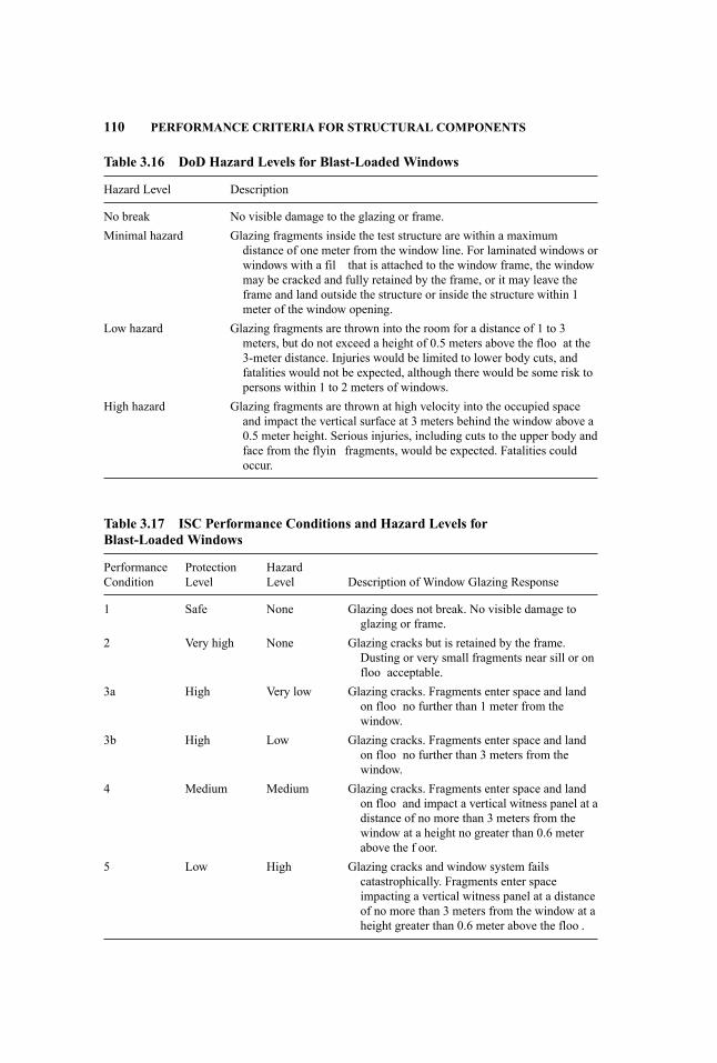
110 PERFORMANCE CRITERIA FOR STRUCTURAL COMPONENTS
Table 3.16 DoD Hazard Levels for Blast-Loaded Windows
Hazard Level Description
No break No visible damage to the glazing or frame.Minimal hazard Glazing fragments inside the test structure are within a maximum
distance of one meter from the window line. For laminated windows orwindows with a fil that is attached to the window frame, the windowmay be cracked and fully retained by the frame, or it may leave theframe and land outside the structure or inside the structure within 1meter of the window opening.
Low hazard Glazing fragments are thrown into the room for a distance of 1 to 3meters, but do not exceed a height of 0.5 meters above the floo at the3-meter distance. Injuries would be limited to lower body cuts, andfatalities would not be expected, although there would be some risk topersons within 1 to 2 meters of windows.
High hazard Glazing fragments are thrown at high velocity into the occupied spaceand impact the vertical surface at 3 meters behind the window above a0.5 meter height. Serious injuries, including cuts to the upper body andface from the flyin fragments, would be expected. Fatalities couldoccur.
Table 3.17 ISC Performance Conditions and Hazard Levels forBlast-Loaded Windows
PerformanceCondition
ProtectionLevel
HazardLevel Description of Window Glazing Response
1 Safe None Glazing does not break. No visible damage toglazing or frame.
2 Very high None Glazing cracks but is retained by the frame.Dusting or very small fragments near sill or onfloo acceptable.
3a High Very low Glazing cracks. Fragments enter space and landon floo no further than 1 meter from thewindow.
3b High Low Glazing cracks. Fragments enter space and landon floo no further than 3 meters from thewindow.
4 Medium Medium Glazing cracks. Fragments enter space and landon floo and impact a vertical witness panel at adistance of no more than 3 meters from thewindow at a height no greater than 0.6 meterabove the f oor.
5 Low High Glazing cracks and window system failscatastrophically. Fragments enter spaceimpacting a vertical witness panel at a distanceof no more than 3 meters from the window at aheight greater than 0.6 meter above the floo .
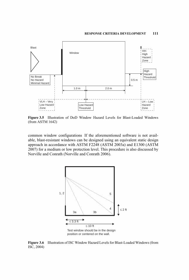
RESPONSE CRITERIA DEVELOPMENT 111
Blast
No BreakNo HazardMinimal Hazard
VLH – VeryLow HazardZone
LH – LowHazardZone
Low HazardThreshold
HighHazardThreshold
HH-HighHazardZone
Window
0.5 m
2.0 m1.0 m
Figure 3.5 Illustration of DoD Window Hazard Levels for Blast-Loaded Windows(from ASTM 1642)
common window configurations If the aforementioned software is not avail-able, blast-resistant windows can be designed using an equivalent static designapproach in accordance with ASTM F2248 (ASTM 2003a) and E1300 (ASTM2007) for a medium or low protection level. This procedure is also discussed byNorville and Conrath (Norville and Conrath 2006).
Test window should be in the designposition or centered on the wall.
1, 2
3a 3b4
5
≤ 2 ft
≤ 3.3 ft
≤ 10 ft
Figure 3.6 Illustration of ISCWindowHazard Levels for Blast-LoadedWindows (fromISC, 2004)

112 PERFORMANCE CRITERIA FOR STRUCTURAL COMPONENTS
Blast-resistant windows are typically designed by vendors according to spec-ification from the design engineer and architect. The specification include thedesign blast load history and information on the required performance criteria.
3.5.6 Response Criteria for Equivalent Static Loads
Previously discussed response criteria based on support rotations and ductilityratios apply for the typical blast design case where the component is designedusing a procedure that explicitly considers the dynamic component response,such as an SDOF-based methodology or dynamic finit element analysis. Somestiff components that are not directly loaded by blast, such as connections andprimary framing members in pure axial loading, have a short response timecompared to the expected rise time of the dynamic reaction load transferred bysupported members, and are usually designed using an equivalent static loadapproach. The load capacity of the stiff component or connection must exceedthe equivalent static reaction load in these cases. If the dynamic analysis showsthe supported member does not yield, the equivalent static reaction load may bebased on the maximum elastic resistance of this member rather than the ultimateresistance. However, this approach should be used with caution, since it will benonconservative if the actual blast load exceeds the design blast load.
The load capacity of the stiff component or connection is usually calculatedusing applicable strength reduction factors from LRFD (load and resistance fac-tor design) (i.e., ∅ factors), although sometimes a ∅ factor of 1.0 is used at thediscretion of the design engineer. Also, the load capacity can include a dynamicincrease factor on the yield strength, but this is typically only 1.05 for high-strength components (i.e., A325 and A490 bolts) and should be applied withcaution for cases where the capacity is controlled by a non-ductile response mode(i.e., axial buckling or anchor bolt pullout from concrete). The equivalent staticreaction load is not multiplied by a load factor.
The equivalent static load approach has conservatism based on the use of a ∅factor less than 1.0 (if applicable), the use of a design load equal to the theoreticalultimate load that can be delivered by the supported component, and the fact thata static approach is used for blast design where the maximum strains are onlyapplied for a few tenths of a second followed by load reversal. However, it is notconservative if the reaction load is applied fast enough by the supported com-ponent compared to the response time of the “stiff” supporting component (i.e.primary framing member) such that dynamic deflection occur greater than thecomponent’s failure deflection This is not a concern for connections since theyare very stiff and respond quickly compared to the application of the reactionload. Also, any component, including primary framing components, can resistthe applied dynamic load regardless of the load rise time if the component hasa load capacity greater than 1.2 times the peak dynamic load, and it can achieveat least a ductility ratio of 3.0 without failing, based on SDOF response chartsin UFC 3-340-02 (UFC, 2008), ASCE (American Society of Civil Engineers1997b), and Biggs (1964).

RESPONSE CRITERIA DEVELOPMENT 113
Table 3.18 Comparison of Response Criteria for Medium Damage
DoD Criteria forAntiterrorism
ASCE BlastDesign for
PetrochemicalFacilitiesa UFC 3-340-02b
Element Type µMAX θMAX µMAX θMAX µMAX θMAX
Reinforced concrete beam — 2 — 2 — 2c
Reinforced concrete slab — 2 — 2 — 1Reinforced masonry walls — 2 — 2 1Prestressed concretecomponents
— 1d — 1d 1 2
Hot-rolled steel beam 3 3 10 6 10 2Cold-formed steel beams — 3 3 3 10 2Corrugated steel panelse — 1 3 2 6 4Open-web steel joists — 3 2 3 4 2Wood studs and beams 2 — — — — —Blast door components f 10–20 6 5–10 8
aResponse criteria from draft of new edition (to be published in 2009).bDesign criteria for Protection Category 1. UFC 3-340-02 does not differentiate between cold-formed and hot-rolled beams.cWith shear reinforcement.dReinforcement index ωp = (Aps/bd)(fps/f′c) < 0.15.ePanels attached to framing at both ends with some tension membrane resistance.fDoor not operable but remains in opening.
3.5.7 Comparisons of Published Response Criteria
The response criteria discussed in this chapter are compared in this section. Caseswhere different published response criteria are in agreement are indicative ofmore accurate correlations between the given response levels and correspond-ing damage or response levels, in the sense that several different organizationsagree with those correlations. Cases where there is not agreement indicate thatmore blast testing is needed for these component types, damage levels, and re-sponse modes to more definit vely establish applicable response criteria. It mustalso be considered that it is not always possible to have direct comparisons be-cause of differences between the definition of response levels by the differentorganizations and the stipulations associated with various response criteria.
Table 3.18 shows comparisons of response criteria for Medium/Moderatedamage from the three sources discussed in this chapter. The criteria from UFC3-340-02 are for design of Protection Category 1 (i.e., personnel protection),which can be considered approximately equivalent to a medium damage level.The comparison shows component types for which there is basic agreement ofthe different criteria and component types for which there is not.

114 PERFORMANCE CRITERIA FOR STRUCTURAL COMPONENTS
Table 3.19 Comparison of Response Criteria for High or Heavy Damage
DoD Criteria forAntiterrorism
ASCE BlastDesign for
PetrochemicalFacilitiesa UFC 3-340-02b
Element Type µMAX θMAX µMAX θMAX µMAX θMAX
Reinforced concrete beam — 5 — 5 — 8c
Reinforced concrete slab — 5 — 5 — 8Reinforced masonry walls — 8 — 5 —Prestressed concretecomponents
— 2d — 2d — —
Hot-rolled steel beam 12 10 20 12 20 12Cold-formed steel beams — 10 12 10 20 12Corrugated steel panels — 4 6 4 — —Open-web steel joists — 6 4 6 — —Wood studs and beams 3 — — — —
aResponse criteria from draft of new edition (to be published in 2009).bDesign criteria for Protection Category 2. UFC 3-340-02 does not differentiate between cold-formed and hot-rolled beams.cWith shear reinforcement.dReinforcement index ωp = (Aps/bd)(fps/f′c) < 0.15.
UFC 3-340-02 is generally more conservative than the other criteria, exceptfor corrugated steel panels. It is difficul to get a good comparison for thiscase because the criteria in UFC 3-340-02 are for panels with “tension mem-brane capacity” without specifying any degree of tension membrane resistance,as is implied in the other two criteria. The DoD and ASCE criteria agree witheach other fairly closely, except for hot-rolled steel beams and corrugated steelpanels.
Table 3.19 shows comparison of response criteria for High, or Heavy, dam-age from the three sources discussed in Section 3.5.1, 3.5.2, and 3.5.3.. The cri-teria from UFC 3-340-02 are for design of Protection Category 2 (i.e., equip-ment protection). All of the criteria in Table 3.19 are considered to representcomponents that are at, or very near, complete failure where they would fall tothe ground or be thrown inside the building. In this case, the response criteriain UFC 3-340-02 are not conservative compared to the criteria from the othersources.
3.6 RESPONSE CRITERIA LIMITATIONS
A limitation of response criteria is that they are only applicable for very specifiresponse modes, since the amount of available ductility is a function of the mode
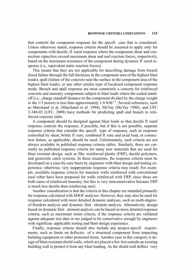
RESPONSE CRITERIA LIMITATIONS 115
that controls the component response for the specifi case that is considered.Unless otherwise stated, response criteria should be assumed to apply only forcomponents with ductile, fl xural response where the component shear and con-nection capacities exceed maximum shear and end reaction forces, respectively,based on the maximum resistance of the component during dynamic fl xural re-sponse (i.e., equivalent static reaction forces).
This means that they are not applicable for describing damage from breach(local failure through the full thickness in the component area of the highest blastloads), spall (failure of the concrete near the surface in the component area of thehighest blast loads), or any other similar type of localized component responsemode. Breach and spall response are most commonly a concern for reinforcedconcrete and masonry components subject to blast loads where the scaled stand-off (i.e., charge standoff distance to the component divided by the charge weightto the 1/3 power) is less than approximately 1.0 ft/lb1/3. Several references, suchas Marchand et al. (Marchand et al. 1994), McVay (McVay 1988), and UFC3-340-02 (UFC, 2008) have methods for predicting spall and breach in rein-forced concrete slabs.
A component should be designed against blast loads so that ductile fl xuralresponse controls the response, if possible, but if this is not possible, separateresponse criteria that consider the specifi type of response, such as responsecontrolled by shear, brittle fl xure, combined fl xure and axial load, or connec-tion failure, as applicable, should be used. Unfortunately, such criteria are notalways available in published response criteria tables. Similarly, there are cur-rently no published response criteria for many new materials that are used forblast resistant design, such as fibe -reinforced plastic (FRP), ductile polymers,and geotextile catch systems. In these situations, the response criteria must bedeveloped on a case-by-case basis by engineers with blast design and testing ex-perience; otherwise, very inappropriate response criteria may result. For exam-ple, available response criteria for masonry walls reinforced with conventionalsteel rebar have been proposed for walls reinforced with FRP, since these areboth cases of reinforced masonry, but this is very nonconservative because FRPis much less ductile than reinforcing steel.
Another consideration is that the criteria in this chapter are intended primarilyfor response calculated with SDOF analyses. However, they may also be used forresponse calculated with more detailed dynamic analyses, such as multi-degree-of-freedom analysis and dynamic finit element analysis. Alternatively, designbased on dynamic finit element analysis can be based on more detailed responsecriteria, such as maximum strain criteria, if the response criteria are validatedagainst adequate test data or are judged to be conservative enough by engineerswith significan applicable testing and blast design experience.
Finally, response criteria should also include any project-specifi require-ments, such as limits on deflectio of a structural component from impactingbuilding equipment or other protected items. Another case in this category is de-sign of blast-resistant shield walls, which are placed a few feet outside an existingbuilding wall to protect it from any blast loading. As the shield wall deflect very
116 PERFORMANCE CRITERIA FOR STRUCTURAL COMPONENTS
quickly from blast load, there is a volume decrease and corresponding pressurebuildup in the annular space between the shield wall and building. The resultingpressure can cause the conventional building wall to fail if the deflectio of theshield wall is not adequately controlled. This is not considered in the availableresponse criteria.
The response criteria also do not address failure of any nonstructural items at-tached to blast-loaded structural components, where acceptable response of walland roof components per the applicable response criteria may cause large enoughrelative accelerations between the component and attached item to rupture theconnection. This is most critical for heavy overhead items. This subject has notbeen studied very much for blast-resistant design, but earthquake-resistant designcan be used for guidance.
REFERENCES
American Society of Civil Engineers. 1997a. Structural Design for Physical Security.New York: American Society of Civil Engineers.
American Society of Civil Engineers, Petrochemical Committee, Task Committee onBlast Resistant Design. 1997b. Design of Blast Resistant Buildings in PetrochemicalFacilities. New York: American Society of Civil Engineers.
American Society of Civil Engineers Structural Engineering Institute. Forthcoming. BlastProtection of Buildings. New York: American Society of Civil Engineers.
Applied Research Associates. 2008. Window Glazing Analysis Response and Design(Wingard) Computer Program, Version 5.5.1. Developed by Applied Research Asso-ciates for the U.S. Government Services Administration (GSA).
ASTM. 2003a. Standard Practice for Specifying an Equivalent 3-Second Duration De-sign Loading for Blast Resistant Glazing Fabricated with Laminated Glass (F2248).West Conshohocken, PA: ASTM International.
. 2003b. Standard Test Method for Metal Doors Used in Blast Resistant Ap-plications (Equivalent Static Load Method) (F2247) West Conshohocken, PA: ASTMInternational.
. 2007. Standard Practice for Determining Load Resistance of Glass in Build-ings (ASTM E1300 - 07e1). West Conshohocken, PA: ASTM International.
Biggs, J. D. 1964. Introduction to Structural Dynamics. New York: McGraw Hill Co.Departments of the Army, the Navy and the Air Force (DOANAF). 1990. Structures toResist the Effects of Accidental Explosions (Department of the Army Technical ManualTM 5-1300, Department of the Navy Publication NAVFAC P-397, Department of theAir Force Manual AFM 88-22). Washington, DC: Departments of the Army, the Navyand the Air Force.
Department of Defense Explosives Safety Board (DDESB). 2004. Ammunition and Ex-plosives Safety Standards (DOD 6055.9). Washington, DC: U.S. Department of De-fense.
Grumbach S. D., C. Naito, and R. J. Dinan. 2007. Use of precast concrete walls for blastprotection of steel stud wall construction. Presented at the 78th Shock and VibrationSymposium, Philadelphia, PA, November 4–8, 2007.
Interagency Security Committee. 2004. ISC Security Design Criteria for New Federal
REFERENCES 117
Offic Buildings and Major Modernization Projects. Washington, DC: Department ofHomeland Security, The Interagency Security Committee.
Marchand K. A., S. Woodson, and T. Knight. 1994. Revisiting concrete spall and breachprediction curves: Strain rate (scale effect) and impulse (pulse length and charge shape)considerations. Presented at the 26th DDESB Explosives Safety Seminar, Miami, FL,August 1994.
McVay, Mark. 1988. Spall Damage of Concrete Structures. Vicksburg, MS: Army Engi-neer Waterways Experimentation Station Structures Lab. Accession No. ADA199225from the Defense Technical Institute Center (DTIC).
Norville H. S. and E. J. Conrath. 2006. Blast-resistant glazing design. Journal of Archi-tectural Engineering 12 (3): 129–136.
Oswald C. J. 2008. Update to response criteria for blast resistant buildings in petrochem-ical facilities. Presented at ASCE Structures Congress 2008, Vancouver, Canada, April24–26, 2008.
Oswald C. J. and D. T. Nebuda. 2006. Development of Component Explosive DamageAssessment Workbook (EDAW). Presented at the 32nd DDESB Explosive Safety Sem-inar, Philadelphia, PA, August 2006.
Oswald C. J., D. T. Nebuda, D. Holgado, and M. Diaz. 2006. Shock tube testing onreinforced masonry walls. Presented at the 32nd DDESB Explosive Safety Seminar,Philadelphia, PA, August 2006.
Panagiotakos T. B. andM. N. Fardis. 2001. Deformations of reinforced concrete membersat yielding and ultimate. ACI Structural Journal 98 (2): 135–148.
Protective Design Center. 2008a. Component Explosive Damage Assessment Workbook(CEDAW) (PDC TR-08-07). Omaha, NE: U.S. Army Corps of Engineers, ProtectiveDesign Center.
. 2008b. Single Degree of Freedom Structural Response Limits for Antiterror-ism Design (PDC TR-06-08). Omaha, NE: U.S. Army Corps of Engineers, ProtectiveDesign Center.
SAFE/SSG (Security Facilities Executive, Special Services Group). 1997. Glazing Haz-ard Guide, Cubicle Standoffs, Tables and Charts, Report No. SSG/EP/4/97. London:Special Services Group/Explosive Protection Group.
Unifie Facilities Criteria Program. 2002. Design and Analysis of Hardened Structuresto Conventional Weapons Effects (FOUO) (UFC 3-340-01). Washington, DC: U.S.Department of Defense, Unifie Facilities Criteria Program.
. 2005. Design of Buildings to Resist Progressive Collapse (UFC 4-023-03).Washington, DC: U.S. Department of Defense, Unifie Facilities Criteria Program.
. 2008. Structures to Resist the Effects of Accidental Explosions (UFC 3-340-02). Washington, DC: U.S. Department of Defense, Unifie Facilities Criteria Program.
U.S. Army Corps of Engineers. 2004. Window Fragment Hazard Level Analysis (HazL),Version 1.2. Vicksburg, MS: USACE Engineer Research and Development Center.
U.S. General Services Administration. 2003. Progressive Collapse Analysis and DesignGuidelines for New Federal Offic Buildings and Major Modernization Projects (June2003). Washington, DC: General Services Administration.
Wesevich J. W., C. J. Oswald, M. T. Edel, M. J. Lowak, and S. S. Alaoui. 2002. Com-pile and Enhance Blast Related CMU Wall Test Database (CMUDS). Prepared for theOffic of Special Technology byWilfred Baker Engineering, Inc., Contract No. 41756-00-C-0900, September 6, 2002.

4 Materials Performance
Andrew Whittaker and John Abruzzo
4.1 INTRODUCTION
The ASCE Standard Blast Protection of Buildings (American Society of CivilEngineers 2009) permits the use of reinforced concrete, masonry, structural steel,and timber in blast-resistant construction. Of these materials, only the two mostcommon materials, namely, structural steel (Section 4.2) and reinforced concrete(Section 4.3) are discussed in this chapter. For each of these materials, constitu-tive models that account for strain-rate and thermal effects, procedures to accountfor strain-rate effects at the macro level, mechanical properties for design, andfailure modes at the component level are discussed. Only those grades of steel,concrete and rebar materials, and components used in the construction of typicalbuildings are discussed. Steel plates, light-gage and cold-formed framing are notstructural components in typical buildings, and the interested reader is directedto UFC 3-340-02 (U.S. Department of Defense 2008) for relevant information.
Section 4.4 discusses the use of strength-reduction factors for the computa-tion of strength of reinforced concrete and steel components and provides therationale for the use of φ = 1in the ASCE Standard.
A list of key references and resource documents is provided at the end of thischapter.
4.2 STRUCTURAL STEEL
4.2.1 Stress-Strain Relationships
Generic uniaxial stress-strain relationships are available for structural steels intextbooks (e.g., Bruneau et al. 1997, Brockenbrough and Merritt 2006) and onthe World Wide Web. Sample stress-strain relationships are presented in Figure4.1 (from Brockenbrough and Merritt 2006). Such relationships are establishedby ASTM-standard tests and can be described using yield stress (σy), tensile(or ultimate) strength (σu), yield strain (εy), strain at the onset of material hard-ening, strain at tensile strength, and strain at rupture. ASTM specification forstructural steels (e.g., A36, A500, A572, A913, and A992) specify minimumvalues for yield and tensile strengths and strain at rupture. Limits can be set on
119
Handbook for Blast-Resistant Design of Buildings Edited by Donald 0. Dusenberry
Copyright 0 2010 by John Wiley & Sons, Inc. All rights reserved.

120 MATERIALS PERFORMANCE
Figure 4.1 Stress-Strain Relationships for Selected Structural Steels at Room Temper-ature and Low Strain Rate (Brockenbrough and Merritt 2006, with permission)
maximum yield strength and maximum ratios of yield-to-tensile-strength can bespecifie for selected ASTM-designated steel. Tests to determine stress-strainrelationships, σ = f (ε), are generally conducted at low speeds and produce re-sults at which strain-rate effects are considered negligible. Data from such rela-tionships, after modificatio for strain-rate effects, are routinely used to computemechanical properties for design.
Rapid or high strain-rate loading affects the mechanical properties of struc-tural steels. High strain-rate data are reported in the literature (e.g., Campbelland Ferguson 1970, Brockenbrough and Merritt 2006, Chang and Lee 1987,Klepaczko 1994, Lee and Liu 2006). The typical effects of increased strain rateon the response of structural steels are an increase in yield stress; an increasein ultimate strength, albeit smaller than for yield stress; and a reduction in theelongation at rupture. The elastic modulus is not substantially affected by strainrate. Sample data for selected steels at three temperatures, from Brockenbroughand Merritt (2006), are presented in Figure 4.2.
4.2.2 Constitutive Models for Structural Steel
Finite element analysis of steel components and structures for blast effects gen-erally involves the use of either solid or shell elements to construct a beam (col-umn) cross section and span or a beam-column element. If solid (shell) elements

STRUCTURAL STEEL 121
Figure 4.2 Effects of Strain Rate on Yield Stress and Tensile Strength at −50◦F, RoomTemperature, and +600◦F (Brockenbrough and Merritt 2006, with permission)
are used to discretize a cross section, as shown in Figure 4.3, an appropriateconstitutive model must be selected for the structural steel. If beam-column ele-ments are used to describe a structural component, the effects of strain rate andtemperature must be accommodated indirectly, as described in Section 4.2.3.
Figure 4.3 Finite Element Model of a W-Shape Steel Cross Section
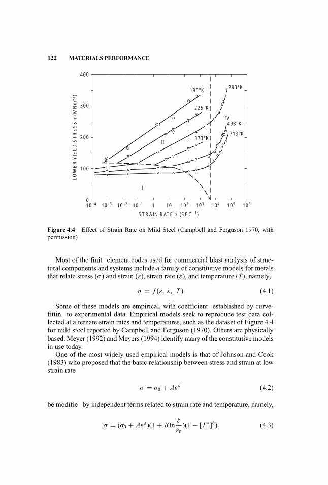
122 MATERIALS PERFORMANCE
400
300
200
100
010–4 10–3 10–2 10–1 1
I
II
IV
STRAIN RATE (SEC–1)
10 102 103 104 105 106
195°K 293°K
225°K
493°K
713°K373°K
LOW
ER
YIE
LD S
TR
ES
S τ
(M
Nm
–2)
∝.
Figure 4.4 Effect of Strain Rate on Mild Steel (Campbell and Ferguson 1970, withpermission)
Most of the finit element codes used for commercial blast analysis of struc-tural components and systems include a family of constitutive models for metalsthat relate stress (σ ) and strain (ε), strain rate (ε), and temperature (T), namely,
σ = f (ε, ε, T ) (4.1)
Some of these models are empirical, with coefficient established by curve-fittin to experimental data. Empirical models seek to reproduce test data col-lected at alternate strain rates and temperatures, such as the dataset of Figure 4.4for mild steel reported by Campbell and Ferguson (1970). Others are physicallybased. Meyer (1992) andMeyers (1994) identify many of the constitutive modelsin use today.
One of the most widely used empirical models is that of Johnson and Cook(1983) who proposed that the basic relationship between stress and strain at lowstrain rate
σ = σ0 + Aεa (4.2)
be modifie by independent terms related to strain rate and temperature, namely,
σ = (σ0 + Aεa)(1+ BInε
ε0)(1− [T ∗]b) (4.3)

STRUCTURAL STEEL 123
where σ0 is the yield stress, a is a hardening coefficient A and B are exper-imentally determined factors, ε0 is a reference strain rate, T ∗ is a normalizedtemperature calculated per Equation 4.4, and b is a coefficien determined bycurve-fittin to data.
T ∗ = T − TrTm − Tr
(4.4)
In Equation 4.4, T is the temperature at which the stress is calculated, Tr is areference temperature at which the yield stress is measured, and Tm is the meltingpoint. The f ve parameters (σ0, A, B, a, b) in the model of Equation 4.3 are deter-mined experimentally. Johnson and Cook (1983), Nicholas and Rajendran (1990)and Meyers (1994) report values of these parameters for a number of materials,but not structural grades of steel used in buildings, bridges, and infrastructure.The Johnson-Cook model treats the effects of strain rate and temperature inde-pendently, which may be invalid for many metals at very high strain rates (Zukas2004, Nicholas and Rajendran 1990).
Other constitutive models are physically based and provide a relationship be-tween stress and strain that accounts for the effects of lattice structure, grain size,strain rate, and temperature. Two models that are implemented in LS-DYNA(Livermore Software Technology Corporation 2003) are Zerilli-Armstrong (Zer-illi and Armstrong 1987, Lee and Liu 2006) and Mechanical Threshold Stress,both of which are described by Meyers (1994) in some detail.
The use of either empirical or physically-based constitutive models in finitelement analysis enables the user to track the effects of strain rate and tempera-ture over the depth and length of a cross section at each time step in the analysis.
4.2.3 Component Level Strain Rate and Temperature Effects
Most applications of the Standard will involve the use of simplifie nonlinearmodels of structural components and indirect treatment of strain-rate effects.Thermal effects are generally ignored because (a) most computer codes usedto compute reflecte pressure histories on components do not return temperaturehistories, and (b) the time frame for the conduction of heat through the depth ofa steel component is often much longer than the duration of the imposed over-pressure.
The most widely used nonlinear component model has a single-degree-of-freedom (SDOF). The properties of the SDOF system are computed using pro-cedures developed by Biggs (1964) and his co-workers at the Massachusetts In-stitute of Technology in the 1950s. These procedures can accommodate pinnedand fi ed boundary conditions and typically assume a uniform distribution ofapplied pressure, which is suitable for far-fiel detonations only. The responseof the nonlinear SDOF system is a function of the mass per unit length, fl xuralstiffness, span, boundary conditions, history of reflecte pressure, and compo-nent resistance function, which is a function of strain rate.

124 MATERIALS PERFORMANCE
Consider the cross section of Figure 4.3 and assume a linear distribution ofstrain across the depth of the section. For W-shape cross sections subjected tomajor-axis bending, axial strain and strain rate will be greatest at the exterioredges of the flange and zero at the neutral axis—strain rate will vary over thedepth of the cross section. For W-shape sections subjected to axial compressionor tension, axial strain and strain rate will be uniform across the depth of thesection.
UFC 3-340-02 (U.S. Department of Defense 2008) provides guidance onthe inclusion of strain-rate effects in the computation of component axial andfl xural strength in the form of stress-increase factors. Information is providedfor ASTM A36 (carbon structural steel), A588 (high-strength, low-alloy struc-tural steel up to 345 MPa minimum yield point), and A514 (high-yield-strengthquenched and tempered alloy steel plate) steels, for fl xure (bending) and axialforce (tension or compression) and low-pressure (far-range detonation, incidentoverpressure less than 100 psi, lower strain rate) and high-pressure (near-rangedetonation, incident overpressure much greater than 100 psi, higher strain rate)loadings.
The UFC presents a simple equation for strain rate, which is assumed to beconstant from zero strain to the yield strain. The equation is reproduced in Equa-tion 4.5, below. The assumption of constant strain rate to yield is not unreason-able given the coarseness of the analysis that generally accompanies the use ofthe stress-increase factors.
ε = fdsEte
(4.5)
where ε is the average strain rate in the elastic range of response, E is the elasticmodulus for steel (29,000 ksi, 200 GPa), te is the time to yield in the cross sec-tion, and fds is the dynamic design stress, which is a function of minimum spec-ifie yield stress, a stress-increase factor, and a factor to relate expected strengthto minimum specifie strength that varies as a function of steel grade. The dy-namic design stress is discussed further in Section 4.2.4
Stress-increase factors, which are termed Dynamic Increase Factors (DIF) inthe UFC and denoted by the symbol c, are used to increase the yield stress andtensile strength of structural steels. Table 4.1, which is adapted from UFC 3-340-02, presents values for c. The values of c that are applied to yield stress arelarger for fl xure than axial force because blast-induced axial forces are likelyapplied indirectly through beam and girder reactions for which the rise time willbe longer and the load effects staggered in time. If a component is subjected tocombined axial force and bending moment (e.g., a column subjected to bendingdue to direct air-blast loading on the column flang and axial force due to indirectloading through air-blast-induced beam/girder reactions), one value of c shouldbe used for component strength calculations and deformation calculations, unlessthe component yield strength can be updated step-by-step in the analysis. Thechosen value of c should reflec the dominant contributor to the combined stress
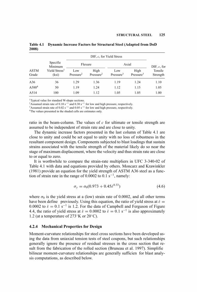
STRUCTURAL STEEL 125
Table 4.1 Dynamic Increase Factors for Structural Steel (Adapted from DoD2008)
DIF, c, for Yield Stress
Flexure Axial
ASTMGrade
SpecifieMinimum
Yield Stress1(ksi)
LowPressure2
HighPressure2
LowPressure3
HighPressure3
DIF, c, forTensileStrength
A36 36 1.29 1.36 1.19 1.24 1.10A5884 50 1.19 1.24 1.12 1.15 1.05A514 100 1.09 1.12 1.05 1.05 1.00
1Typical value for standard W-shape sections.2Assumed strain rate of 0.10 s−1 and 0.30 s−1 for low and high pressure, respectively.3Assumed strain rate of 0.02 s−1 and 0.05 s−1 for low and high pressure, respectively.4The values presented in the shaded cells are estimates only.
ratio in the beam-column. The values of c for ultimate or tensile strength areassumed to be independent of strain rate and are close to unity.
The dynamic increase factors presented in the last column of Table 4.1 areclose to unity and could be set equal to unity with no loss of robustness in theresultant component design. Components subjected to blast loadings that sustainstrains associated with the tensile strength of the material likely do so near thestage of maximum displacement, where the velocity and thus strain rate are closeto or equal to zero.
It is worthwhile to compare the strain-rate multipliers in UFC 3-340-02 ofTable 4.1 with data and equations provided by others. Moncarz and Krawinkler(1981) provide an equation for the yield strength of ASTM A36 steel as a func-tion of strain rate in the range of 0.0002 to 0.1 s−1, namely:
σy = σ0(0.973+ 0.45ε0.33) (4.6)
where σ0 is the yield stress at a (low) strain rate of 0.0002, and all other termshave been define previously. Using this equation, the ratio of yield stress at ε =0.0002 to ε = 0.1 s−1 is 1.2. For the data of Campbell and Ferguson of Figure4.4, the ratio of yield stress at ε = 0.0002 to ε = 0.1 s−1 is also approximately1.2 (at a temperature of 273◦K or 20◦C).
4.2.4 Mechanical Properties for Design
Moment-curvature relationships for steel cross sections have been developed us-ing the data from uniaxial tension tests of steel coupons, but such relationshipsgenerally ignore the presence of residual stresses in the cross section that re-sult from the fabrication of the rolled section (Bruneau et al. 1997). Simplifiebilinear moment-curvature relationships are generally sufficien for blast analy-sis computations, as described below.
126 MATERIALS PERFORMANCE
The fl xural, axial, and shear strengths of steel components are typically de-fine in terms of cross section properties (e.g., area, web area, elastic moduli,plastic moduli) and either yield stress or tensile strength. For blast-resistantdesign in accordance with the Standard, these stresses can be increased to adynamic design stress by factors to account for strain-rate effects (see Sec-tion 4.2.2) and material strengths in excess of minimum specifie stresses orstrengths.
UFC 3-340-02 presents a widely accepted procedure for computing so-calleddynamic design stresses. The focus of the UFC presentation is fl xure. Alter-nate computations are made for ductility ratios of less than or equal to 10 andductility ratios greater than 10. Therein, ductility is define as the ratio of max-imum deflectio to yield deflection Although large lateral deflection may beacceptable to a designer, careful consideration must be given to geometry ofthe cross section at these deflections because the cross section may no longerbe prismatic due to either element deformation due to direct air-blast loading(see Figure 4.5) or cross section instability caused by flang (web) local buck-ling or lateral-torsional buckling. If the component cross section is distorted, thedesign equations presented herein, in UFC 3-340-02 and the AISC Steel Con-struction Manual (American Institute of Steel Construction 2006), cannot beused for component checking.
For ductility ratios of 10 and less, the dynamic design stress, fds , can be com-puted per Equation 4.7 as the product of the minimum specifie yield stress, fy ,a ratio of the expected yield stress to the minimum specifie yield stress, Ry , anda Dynamic Increase Factor, c, namely,
fds = fdy = fy Ryc (4.7)
where Ry can be taken as either (a) 1.1 for fy of 50 ksi (345 MPa) or less and 1.0otherwise, or (b) per Table I-4-1 of the AISC Seismic Provisions for Steel Build-ings (American Institute of Steel Construction 2005) for new structural steel, c isgiven in Table 4.1 or established on the basis of test data, and fdy is the dynamicyield stress. For evaluation of older structural members constructed with A36steel, Ry should be set equal to 1.1 unless test data indicate that a greater valueis appropriate.
For ductility ratios of greater than 10, the UFC acknowledges the increase insteel stress due to strain hardening per Equation 4.8. The relationship betweenfds and ductility ratio must be considered approximate because displacementsand peak strains do not scale linearly. Importantly, the technical basis for theincrease in stress beyond the dynamic yield stress is not provided in the UFC.
fds = fdy + fdu − fdy4
(4.8)
where fdy is the dynamic yield stress per Equation 4.7, and fdu is the dynamicultimate stress. In the UFC, the dynamic ultimate stress is taken as the product

STRUCTURAL STEEL 127
Figure 4.5 Steel Cross Section Distorted Due to Air-Blast Loading (Courtesy ofAmerican Institute of Steel Construction)
of the specifie minimum tensile strength and c per Table 4.1. Alternately, thedynamic design stress at high deformation can also account for the expectedincrease in tensile strength above the specifie minimum value, namely,
fds = fdy + cRt fy − fdyα
(4.9)
where values of Ry are provided in Table I-4-1 of Seismic Provisions for SteelBuildings (American Institute of Steel Construction 2005), and α is specifie bythe user, but can be taken as 4.
4.2.5 Failure Modes of Structural Components
Introduction This section of the handbook presents introductory informationon typical failure modes (fl xural response, shear response, combined fl x-ural and axial response, instability) of structural shapes, with emphasis onW-shapes loaded in the plane of the web. The focus is on design of new structuralcomponents rather than assessment of existing components.
For assessment of existing structural components whose geometries and/ormaterials do not comply with modern standards such as AISC (American
128 MATERIALS PERFORMANCE
Institute of Steel Construction 2005, 2006), the designer is encouraged touse first-principle mechanics to determine whether performance is acceptable.Knowledge of the component deformation demands may enable a relaxation ofthe element compactness and component bracing rules required by Seismic Pro-visions for Structural Steel Buildings (AISC 2005) and adopted by-and-largebelow.
Flexure Procedures for the computation of fl xural strength of prismatic crosssections as a function of unbraced length of the compression flang and elementcompactness are well established and reported in textbooks and the literature. Forthe simplest case, where the unbraced length is zero, the cross section is compact,and the strain rate is low, the fl xural strength is computed as the product of theplastic section modulus and the minimum specifie yield stress.
For component checking involving blast load effects, the fl xural strength canbe calculated as the product of the plastic section modulus and the dynamic de-sign stress per Section 4.2.3, provided the cross section is seismically compactper Table I-8-1 of AISC (2005) and laterally braced per Section 9.8 of AISC(2005). Lateral bracing of both flange is generally required to address rebound.
Shear The capacity of a steel beam or column in shear can be computed as theproduct of the shear area and the dynamic yield stress in shear. For a W-shapeloaded in the plane of its web, the shear area shall not exceed the web area. Thedynamic yield stress in shear, fdv , may be computed as
fdv = 0.60 fdy (4.10)
where fdy is calculated per Equation 4.7. At the connection of such a W-shapebeam to the flang of a W-shape column, the distributions of stress and strainwill not follow beam theory, and a significan percentage of the shear force inthe beam will be transmitted to the column via the beam flange (e.g., Kim et al.2002).
Flexure and Axial Load For checking components subjected to blast load ef-fects that produce fl xure and axial load, the procedures of Section 9 of AISC(2005) and AISC (2006) should be followed to compute coexisting axial andfl xural strengths.
Splices in components subjected to both fl xure and axial load should developthe capacity of the cross section computed assuming the dynamic design stress.
Flexure-axial-shear interaction need not be considered for a W-shape sectionloaded in the plane of its web if the blast-induced shear force is less than shearcapacity of the cross section calculated using Equation 4.10 and the ratio of theplastic section modulus of the web alone to that of the W-shape is small.
Element and Component Instability Element instability (e.g., flang andweb local buckling, web crippling and tearing) and/or component instability

REINFORCED CONCRETE 129
(e.g., lateral-torsional buckling) can prevent a cross section from attaining itsplastic capacity.
Design and detailing of new structural components to resist blast load ef-fects should follow the AISC Seismic Provisions for Structural Steel Buildings(AISC 2005) unless the component deformations are small. For component duc-tility demands of 3 and greater, cross sections should be seismically compact perTable I-8-1 of the AISC Seismic Provisions. For component ductility demandsof less than 3, cross sections should be compact per Table B4.1of the AISC SteelConstruction Manual (AISC 2006).
Crippling or tearing of webs inW-shape cross sections may result from the ap-plication of concentrated loads by other framing members. Design against crip-pling or tearing should conform with Section J10 of AISC (2006), with no al-lowance for increase in yield stress above the expected value due to strain ratebecause the rise time of the loading will likely be much longer than the durationof the air-blast loading.
Lateral bracing of W-shape flange to delay lateral-torsional buckling shouldgenerally follow the rules of AISC (2005) for seismic design. Alternate limitson unbraced length that vary as a function of the component deformation areprovided in UFC 3-340-02 and can be used in lieu of those presented in Section9.8 of AISC (2005).
4.3 REINFORCED CONCRETE
4.3.1 Stress-Strain Relationships for Concrete
Many textbooks present stress-strain relationships for concrete in uniaxial com-pression. Sample relationships are presented in Figure 4.6 from Wight andMacGregor (2008) for concrete with compressive strength ( f ′
c) ranging between4500 psi (31 MPa) and 17500 psi (120 MPa). As with structural steel, the stress-strain relationships are established using an ASTM-standard test, which is con-ducted at a low stress rate of the order of 30 psi per second and causes failurein 90 to 180 seconds. An increase in compressive strength is accompanied byincrease in the modulus of elasticity (secant modulus in the figur to a stress ofapproximately0.5 f ′
c), an increase in the strain at maximum stress, an increase inthe slope of the softening branch of the stress-strain relationship, and a decreasein the maximum concrete strain. The modulus of elasticity in units of psi fornormal-weight concrete with a density of 145 lb/ft3 is often taken per ACI 318(American Concrete Institute 2008) as
Ec = 57000√f ′c (4.11)
where f ′c is in units of psi. Values of compressive strength are used to compute
mechanical properties for design after modificatio for strain-rate effects, as de-scribed in Section 4.3.5 below.
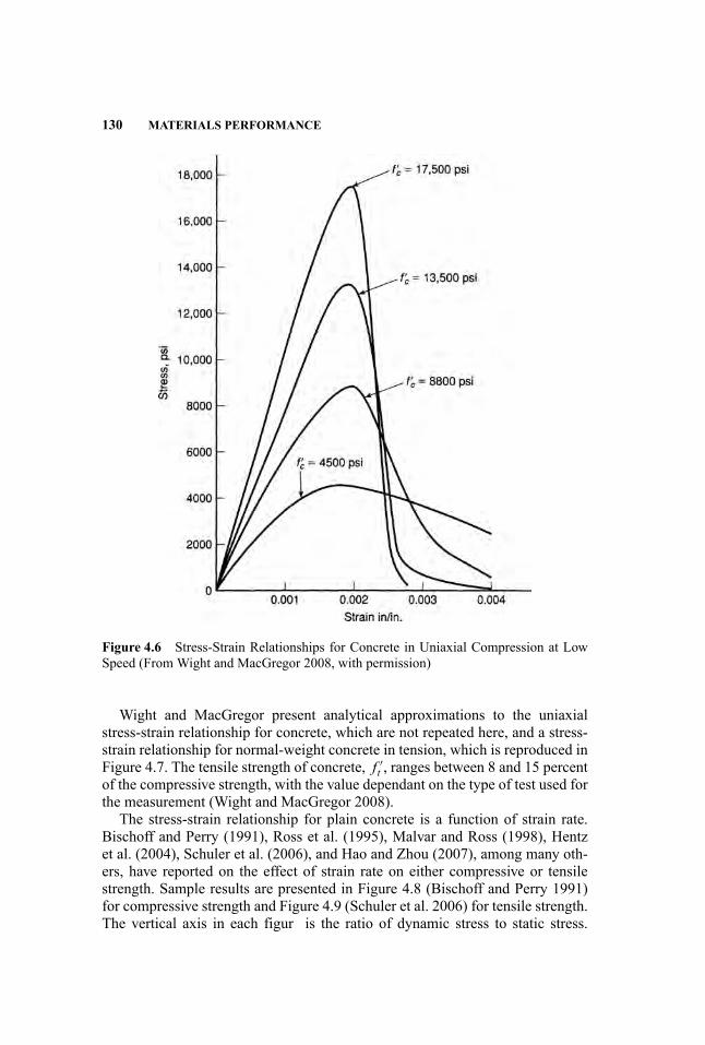
130 MATERIALS PERFORMANCE
Figure 4.6 Stress-Strain Relationships for Concrete in Uniaxial Compression at LowSpeed (From Wight and MacGregor 2008, with permission)
Wight and MacGregor present analytical approximations to the uniaxialstress-strain relationship for concrete, which are not repeated here, and a stress-strain relationship for normal-weight concrete in tension, which is reproduced inFigure 4.7. The tensile strength of concrete, f ′
t , ranges between 8 and 15 percentof the compressive strength, with the value dependant on the type of test used forthe measurement (Wight and MacGregor 2008).
The stress-strain relationship for plain concrete is a function of strain rate.Bischoff and Perry (1991), Ross et al. (1995), Malvar and Ross (1998), Hentzet al. (2004), Schuler et al. (2006), and Hao and Zhou (2007), among many oth-ers, have reported on the effect of strain rate on either compressive or tensilestrength. Sample results are presented in Figure 4.8 (Bischoff and Perry 1991)for compressive strength and Figure 4.9 (Schuler et al. 2006) for tensile strength.The vertical axis in each figur is the ratio of dynamic stress to static stress.
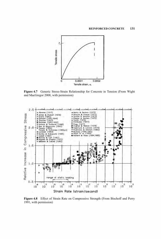
REINFORCED CONCRETE 131
Figure 4.7 Generic Stress-Strain Relationship for Concrete in Tension (From Wightand MacGregor 2008, with permission)
Figure 4.8 Effect of Strain Rate on Compressive Strength (From Bischoff and Perry1991, with permission)

132 MATERIALS PERFORMANCE
Figure 4.9 Effect of Strain Rate on Tensile Strength of Concrete (From Schuler et al.2006, with permission)
Appreciable increases in both compressive and tensile strength are evident atstrain rates greater than 0.1 s−1.
4.3.2 Stress-strain Relationships for Reinforcement
Typical stress-strain relationships for steel reinforcement (or rebar) are presentedin standards and textbooks. Figure 4.10 presents a typical stress-strain relation-ship for Grade 60 rebar from Malvar (1998). Grade 60 reinforcement is pro-duced in accordance with a number of ASTM standards, including ASTM A615and ASTM A704. ASTM A706 rebar is often used for seismic and blast appli-cations where weldability, ductility, and bendability are important (Wight andMacGregor 2008).
As with structural steel, the stress-strain relationship for steel reinforcementis a function of strain rate. Sample data from Malvar (1998) showing the effectof strain rate on yield stress and tensile strength are presented in Figure 4.11 and4.12. The greatest increases in yield stress and tensile strength are observed forthe lower grades of rebar, and the percentage increases in yield stress are greaterthan those in tensile strength.
4.3.3 Constitutive Modeling of Concrete and Rebar
Introduction Finite element models of reinforced concrete components andstructures for air-blast analysis will generally use either solid elements to mesh a

REINFORCED CONCRETE 133
Figure 4.10 Typical Stress-Strain Relationship for Grade 60 Steel Reinforcement(From Malvar 1998, with permission)
cross section along a span or a beam-column element. If solid elements are usedto discretize a cross section, appropriate constitutive models must be selectedfor the concrete and reinforcement, and algorithms and elements introduced tomodel bond between the concrete and reinforcement. The following subsectionsof Section 4.3.3 introduce constitutive models for plain concrete and reinforce-ment. If beam-column elements are used to model and analyze a reinforced
Figure 4.11 Effect of Strain Rate on Yield Stress of Steel Reinforcement (FromMalvar1998, with permission)
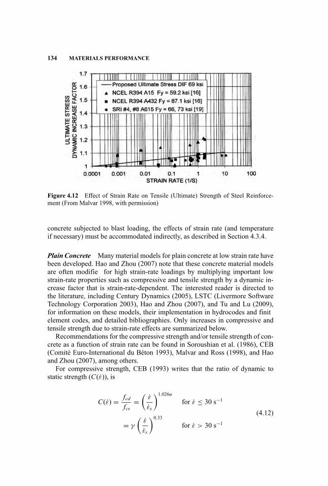
134 MATERIALS PERFORMANCE
Figure 4.12 Effect of Strain Rate on Tensile (Ultimate) Strength of Steel Reinforce-ment (From Malvar 1998, with permission)
concrete subjected to blast loading, the effects of strain rate (and temperatureif necessary) must be accommodated indirectly, as described in Section 4.3.4.
Plain Concrete Many material models for plain concrete at low strain rate havebeen developed. Hao and Zhou (2007) note that these concrete material modelsare often modifie for high strain-rate loadings by multiplying important lowstrain-rate properties such as compressive and tensile strength by a dynamic in-crease factor that is strain-rate-dependent. The interested reader is directed tothe literature, including Century Dynamics (2005), LSTC (Livermore SoftwareTechnology Corporation 2003), Hao and Zhou (2007), and Tu and Lu (2009),for information on these models, their implementation in hydrocodes and finitelement codes, and detailed bibliographies. Only increases in compressive andtensile strength due to strain-rate effects are summarized below.
Recommendations for the compressive strength and/or tensile strength of con-crete as a function of strain rate can be found in Soroushian et al. (1986), CEB(Comite Euro-International du Beton 1993), Malvar and Ross (1998), and Haoand Zhou (2007), among others.
For compressive strength, CEB (1993) writes that the ratio of dynamic tostatic strength (C(ε)), is
C(ε) = fcdfcs
=(
ε
εs
)1.026α
for ε ≤ 30 s−1
= γ
(ε
εs
)0.33
for ε > 30 s−1(4.12)

REINFORCED CONCRETE 135
where fcd is the dynamic compressive strength at strain rate ε in the range of30 × 10−6s−1 to 300 s−1, fcs is the static compressive strength at a referencestrain rate εs of 30 × 10−6s−1, log γ = 6.156α − 2, α = 1/(5+ 9 fcs/ fco), andfco = 1450 psi (=10 MPa). Malvar and Crawford (1998) noted that the CEBmodel for compressive strength properly fitte the data available at the time oftheir writing.
Gebbeken and Rupert (2000) proposed the multiplier of Equation 4.13 forstrength increases in compression (C) and tension (T),
C(η) = T (η) ={(1+ tanh[0.4(log η − 2)])×
(FmWy
− 1)}Wy (4.13)
where η is a strain rate normalized by a reference value of 1 s−1, log is the com-mon logarithm, Fm is a variable that limits the increase at very high strain rates,and Wy is a variable that controls the shape of the function. Values of the vari-ables are different in tension and compression (Gebbeken 2009).
Johnson and Holmquist (1992) presented the multiplier of Equation 4.14 forstrain-rate-related strength increases in tension and compression,
C(η) = T (η) = 1+ cLn(η) (4.14)
where c is a constant equal to 0.007 (Hao and Zhou 2007), Ln is the naturallogarithm, and all terms have been define previously. An identical equationwas adopted by Riedel et al. (1999) for the RHT model and implemented inAUTODYN (Century Dynamics 2005).
For tensile strength, CEB (Comite Euro-International du Beton 1990) writesthat the ratio of dynamic to static strength (T (ε)), is
T (ε) = ftdfts
=(
ε
εs
)1.016δ
for ε ≤ 30 s−1
= β
(ε
εs
)0.33
for ε > 30 s−1(4.15)
where ftd is the dynamic tensile strength at strain rate ε in the range of 3×10⁻⁶s−1 to 300 s−1, fts is the static tensile strength at a reference strain rate εs of3× 10−6 s−1, logβ = 7.112δ − 2.33, δ = 1/(10+ 6 fcs/ fco), and fco = 10MPa(=1450 psi). Malvar and Ross (1998) modifie the CEB equations as follows,
T (ε) = ftdfts
=(
ε
εs
)δ
for ε ≤ 1 s−1
= β
(ε
εs
)0.33
for ε > 1 s−1(4.16)

136 MATERIALS PERFORMANCE
where ftd is the dynamic tensile strength at strain rate ε in the range of 10−6s−1to 160 s−1, fts is the static tensile strength at a reference strain rate εsof 10−6s−1,logβ = 6δ − 2, δ = 1/(1+ 8 fcs/ fco), and fco = 10 MPa (=1450 psi). Hao andZhou (2007) proposed an alternate formulation based on the data of Figure 4.9,namely,
T (ε) = 1.0 for ε ≤ 1 s−1= 2.06+ 0.26 log(ε) for 10−4 s−1 ≤ ε ≤ 1 s−1= 2.06+ 2.0 log(ε) for 1 s−1 < ε ≤ 103 s−1
(4.17)
where all terms are define previously.
Rebar Materials models for rebar are generally identical to those for structuralsteels as described in Section 4.2.2: Zhou et al. (2008) used the Johnson andCook (1983) material model to characterize the high-strain-rate response of rebarin slabs constructed of conventional concrete and steel-fibe -reinforced concrete.
4.3.4 Component Level Strain-Rate Effects
Similar to steel structures, most reinforced concrete components will be ana-lyzed and designed for air-blast effects using nonlinear single-degree-of-freedom(SDOF) models and an indirect treatment of strain-rate effects, as introduced inSection 4.2.3.
UFC 3-340-02 (U.S. Department of Defense 2008) provides guidance on theinclusion of strain-rate effects for the computation of component axial, fl xural,and shear strength. The tensile strength of concrete is ignored for axial and fl xu-ral strength calculations. Strain-rate effects are addressed using stress-increase ordynamic increase factors for material strength. Information is provided for con-crete compressive and tensile strength and steel reinforcement yield stress andtensile (ultimate) strength in alternate formats, including functions of strain-rateand either far-design (low pressure) or close-in design (high-pressure) loadings.
As with calculations for structural steel, the UFC presents simple calculationsfor average strain rate for concrete and rebar, which is assumed to be constant.The calculations are based on an estimate of the time to yield of reinforcementand the strain in the materials at yield of the cross section. For rebar, the averagestrain rate is computed as
εs = fdyEte
(4.18)
where εs is the average strain rate in the elastic range of response, E is the elasticmodulus for steel rebar (29,000 ksi, 200 GPa), te is the time to yield of the crosssection (generally computed using response charts), and fdy is the dynamic yieldstress, which is a function of minimum specifie yield stress, a stress (dynamic)
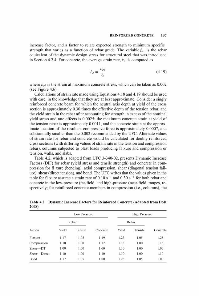
REINFORCED CONCRETE 137
increase factor, and a factor to relate expected strength to minimum specifiestrength that varies as a function of rebar grade. The variable fds is the rebarequivalent of the dynamic design stress for structural steel that was introducedin Section 4.2.4. For concrete, the average strain rate, εc, is computed as
εc = εc0
te(4.19)
where εc0 is the strain at maximum concrete stress, which can be taken as 0.002(see Figure 4.6).
Calculations of strain rate made using Equations 4.18 and 4.19 should be usedwith care, in the knowledge that they are at best approximate. Consider a singlyreinforced concrete beam for which the neutral axis depth at yield of the crosssection is approximately 0.30 times the effective depth of the tension rebar, andthe yield strain in the rebar after accounting for strength in excess of the nominalyield stress and rate effects is 0.0025: the maximum concrete strain at yield ofthe tension rebar is approximately 0.0011, and the concrete strain at the approx-imate location of the resultant compressive force is approximately 0.0007, andsubstantially smaller than the 0.002 recommended by the UFC. Alternate valuesof strain rate for rebar and concrete would be calculated for doubly reinforcedcross sections (with differing values of strain rate in the tension and compressionrebar), columns subjected to blast loads producing fl xure and compression ortension, walls, and slabs.
Table 4.2, which is adapted from UFC 3-340-02, presents Dynamic IncreaseFactors (DIF) for rebar (yield stress and tensile strength) and concrete in com-pression for fl xure (bending), axial compression, shear (diagonal tension fail-ure), shear (direct tension), and bond. The UFC writes that the values given in thetable for fl xure assume a strain rate of 0.10 s−1 and 0.30 s−1 for both rebar andconcrete in the low-pressure (far-field and high-pressure (near-field ranges, re-spectively; for reinforced concrete members in compression (i.e., columns), the
Table 4.2 Dynamic Increase Factors for Reinforced Concrete (Adapted from DoD2008)
Low Pressure High Pressure
Rebar Rebar
Action Yield Tensile Concrete Yield Tensile Concrete
Flexure 1.17 1.05 1.19 1.23 1.05 1.25Compression 1.10 1.00 1.12 1.13 1.00 1.16Shear—DT 1.00 1.00 1.00 1.10 1.00 1.00Shear—Direct 1.10 1.00 1.10 1.10 1.00 1.10Bond 1.17 1.05 1.00 1.23 1.05 1.00
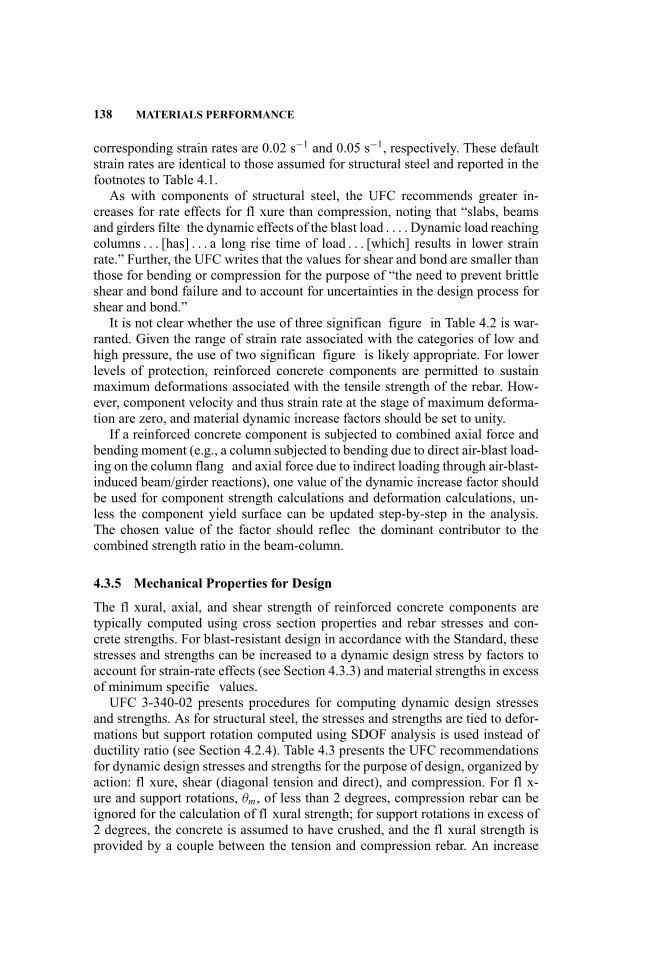
138 MATERIALS PERFORMANCE
corresponding strain rates are 0.02 s−1 and 0.05 s−1, respectively. These defaultstrain rates are identical to those assumed for structural steel and reported in thefootnotes to Table 4.1.
As with components of structural steel, the UFC recommends greater in-creases for rate effects for fl xure than compression, noting that “slabs, beamsand girders filte the dynamic effects of the blast load . . . . Dynamic load reachingcolumns . . . [has] . . . a long rise time of load . . . [which] results in lower strainrate.” Further, the UFC writes that the values for shear and bond are smaller thanthose for bending or compression for the purpose of “the need to prevent brittleshear and bond failure and to account for uncertainties in the design process forshear and bond.”
It is not clear whether the use of three significan figure in Table 4.2 is war-ranted. Given the range of strain rate associated with the categories of low andhigh pressure, the use of two significan figure is likely appropriate. For lowerlevels of protection, reinforced concrete components are permitted to sustainmaximum deformations associated with the tensile strength of the rebar. How-ever, component velocity and thus strain rate at the stage of maximum deforma-tion are zero, and material dynamic increase factors should be set to unity.
If a reinforced concrete component is subjected to combined axial force andbending moment (e.g., a column subjected to bending due to direct air-blast load-ing on the column flang and axial force due to indirect loading through air-blast-induced beam/girder reactions), one value of the dynamic increase factor shouldbe used for component strength calculations and deformation calculations, un-less the component yield surface can be updated step-by-step in the analysis.The chosen value of the factor should reflec the dominant contributor to thecombined strength ratio in the beam-column.
4.3.5 Mechanical Properties for Design
The fl xural, axial, and shear strength of reinforced concrete components aretypically computed using cross section properties and rebar stresses and con-crete strengths. For blast-resistant design in accordance with the Standard, thesestresses and strengths can be increased to a dynamic design stress by factors toaccount for strain-rate effects (see Section 4.3.3) and material strengths in excessof minimum specifie values.
UFC 3-340-02 presents procedures for computing dynamic design stressesand strengths. As for structural steel, the stresses and strengths are tied to defor-mations but support rotation computed using SDOF analysis is used instead ofductility ratio (see Section 4.2.4). Table 4.3 presents the UFC recommendationsfor dynamic design stresses and strengths for the purpose of design, organized byaction: fl xure, shear (diagonal tension and direct), and compression. For fl x-ure and support rotations, θm , of less than 2 degrees, compression rebar can beignored for the calculation of fl xural strength; for support rotations in excess of2 degrees, the concrete is assumed to have crushed, and the fl xural strength isprovided by a couple between the tension and compression rebar. An increase
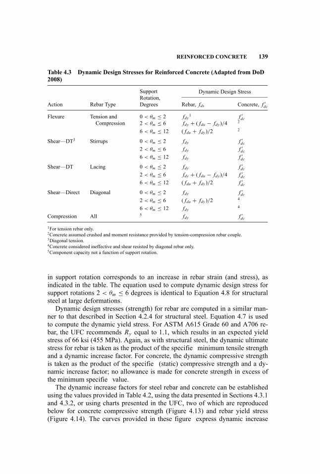
REINFORCED CONCRETE 139
Table 4.3 Dynamic Design Stresses for Reinforced Concrete (Adapted from DoD2008)
Dynamic Design Stress
Action Rebar Type
SupportRotation,Degrees Rebar, fds Concrete, f ′
dc
Flexure Tension andCompression
0 < θm ≤ 2 fdy1 f ′dc
2 < θm ≤ 6 fdy + ( fdu − fdy)/4 2
6 < θm ≤ 12 ( fdu + fdy)/2 2
Shear—DT3 Stirrups 0 < θm ≤ 2 fdy f ′dc
2 < θm ≤ 6 fdy f ′dc
6 < θm ≤ 12 fdy f ′dc
Shear—DT Lacing 0 < θm ≤ 2 fdy f ′dc
2 < θm ≤ 6 fdy + ( fdu − fdy)/4 f ′dc
6 < θm ≤ 12 ( fdu + fdy)/2 f ′dc
Shear—Direct Diagonal 0 < θm ≤ 2 fdy f ′dc
2 < θm ≤ 6 ( fdu + fdy)/2 4
6 < θm ≤ 12 fdy 4
Compression All 5 fdy f ′dc
1For tension rebar only.2Concrete assumed crushed and moment resistance provided by tension-compression rebar couple.3Diagonal tension.4Concrete considered ineffective and shear resisted by diagonal rebar only.5Component capacity not a function of support rotation.
in support rotation corresponds to an increase in rebar strain (and stress), asindicated in the table. The equation used to compute dynamic design stress forsupport rotations 2 < θm ≤ 6 degrees is identical to Equation 4.8 for structuralsteel at large deformations.
Dynamic design stresses (strength) for rebar are computed in a similar man-ner to that described in Section 4.2.4 for structural steel. Equation 4.7 is usedto compute the dynamic yield stress. For ASTM A615 Grade 60 and A706 re-bar, the UFC recommends Ry equal to 1.1, which results in an expected yieldstress of 66 ksi (455 MPa). Again, as with structural steel, the dynamic ultimatestress for rebar is taken as the product of the specifie minimum tensile strengthand a dynamic increase factor. For concrete, the dynamic compressive strengthis taken as the product of the specifie (static) compressive strength and a dy-namic increase factor; no allowance is made for concrete strength in excess ofthe minimum specifie value.
The dynamic increase factors for steel rebar and concrete can be establishedusing the values provided in Table 4.2, using the data presented in Sections 4.3.1and 4.3.2, or using charts presented in the UFC, two of which are reproducedbelow for concrete compressive strength (Figure 4.13) and rebar yield stress(Figure 4.14). The curves provided in these figure express dynamic increase

140 MATERIALS PERFORMANCE
Figure 4.13 Effect of strain rate on compressive strength of concrete with f ′c in the
range of 2500 to 5000 psi (From DoD 2008)
Figure 4.14 Effect of strain rate on the yield stress and tensile strength of rebar (FromDoD 2008)

REINFORCED CONCRETE 141
factors as a function of strain rate. Figure 4.13 represents a reasonable lowerbound on the data of Bischoff and Perry and the CEB recommendations of Equa-tion 4.12 for a concrete strength of 50 MPa (7250 psi) and strain rates of 10 s−1and less. Note that the strain rate in this figur is presented in units of msec.The curves of Figure 4.14 for the yield and tensile strength of rebar are in closeagreement with the recommendations of Malvar (1998).
4.3.6 Component-Level Failure Modes
Introduction This section of the handbook presents introductory informationon typical failure modes (fl xural response, shear response, combined fl xuraland axial response) of reinforced concrete members. The focus is on design ofnew structural components rather than assessment of existing components. Thereader is referred to the literature for information on external reinforcement ofconcrete elements for blast resistance using steel plate and carbon fibe poly-meric materials (e.g., Crawford et al. 2001, Buchan and Chen 2007).
Exactly as with structural steel, the designer is encouraged to use firstprinciples mechanics to determine whether performance is acceptable. The fail-ure mechanisms considered here assume that the core of the reinforced con-crete cross section is intact. Spalling and scabbing may occur, and the depthof reinforced sections should be restricted to core dimensions in such cases.Reinforced concrete components are susceptible to brisance, or shattering, fornear-fiel detonations. The likelihood of shattering should be checked, and thereader is directed to the literature for appropriate procedures.
The following subsections address the common failure modes of reinforcedconcrete components under blast loading. Much additional information onfailure modes can be found in the literature, including UFC 3-340-02 (U.S.Department of Defense 2008), Krauthammer’s Modern Protective Structures(Krauthammer 2008), Mays and Smith’s Blast Effects on Buildings (Mays andSmith 1995), and Smith and Hetherington’s Blast and Ballistic Loading of Struc-tures (Smith and Hetherington 1994).
Flexure Procedures for the computation of fl xural strength of prismatic crosssections are well established. Flexural failure can occur in either brittle or duc-tile modes, depending upon the volume of steel reinforcement in the fl xuralelement. Economical design of reinforced concrete components to resist blastloads generally requires ductile detailing to accommodate the large expected de-formations while maintaining near-peak strength. Confinemen in the form ofseismic hoops or lacing may be required.
For component checking involving blast effects, the fl xural strength can becomputed using the dynamic design stresses of Table 4.3 and compression-tension force couples. If the support rotations are less than 2 degrees, fl xuralstrength is computed using traditional procedures that assume that the tensionrebar yields prior to the concrete in the compression block crushing. For sup-port rotations in the range of 2 to 6 degrees, the cover concrete is assumed to be
142 MATERIALS PERFORMANCE
lost, equal amounts of compression and tension rebar should be provided, andthe fl xural strength is computed using a force-couple involving the compres-sion and tension rebar. For support rotations in excess of 6 degrees and less than12 degrees, equal amounts of compression and tension rebar must be provided,the fl xural strength is computed as a force-couple between the compression andtension rebar, and the rebar layers must be adequately tied. Shear reinforcementin the form of ties (stirrups) or lacing is generally required to sustain supportrotations greater than 2 degrees. UFC 3-340-02 provides guidance on the designof such reinforcement.
For robustness, the minimum longitudinal reinforcement in slabs and beamsmust meet the requirements of ACI 318 for load combinations not involvingblast effects. UFC 3-340-02 also requires a minimum amount of tension andcompression fl xural rebar to be provided in slabs, but not less than that requiredto resist the effects of direct air-blast loading and rebound. These limits for slabstend to be smaller than those of Section 10.5 of ACI 318, although a minimumamount of compression rebar must be provided in all cases.
Shear Four modes of shear failure in reinforced concrete components must beaddressed: (1) diagonal tension, (2) diagonal compression, (3) direct shear, and(4) punching shear. Critical cross sections are at a distance (a) equal to the ef-fective depth of the cross section from the support for diagonal tension and com-pression checks for loadings that produce compression in the support and at theface of the support otherwise, and (b) at the face of the support for direct shear.Punching shear is checked for slabs around isolated supports (e.g., columns) andapplied loads. Concrete and rebar strengths for component checking can be in-creased for strain-rate effects per Tables 4.2 and 4.3.
Design against failure by diagonal compression or tension follows the proce-dure set forth in Chapter 11 of ACI 318. Diagonal compression failure is avoidedin beams (slabs) equipped with stirrups by limiting the nominal shear stress atthe critical section to 10
√f ′dc, where f ′
dc is the concrete dynamic design stressper Tables 4.2 and 4.3. Diagonal tension failure is avoided by ensuring that thesum of the shear resistance provided by the concrete and the stirrups exceeds ap-plied shear force. ACI 318 Sections 11.2.1.1, 11.2.1.2, and 11.2.2.3.can be usedto compute the shear resistance provided by concrete under no axial load, ax-ial compression, and axial tension, respectively. ACI 318 Sections 11.4.7.2 and11.4.7.4 present equations for establishing the required area of shear reinforce-ment perpendicular to the axis of the member (i.e., stirrups) and inclined to theaxis of the member (i.e., lacing bars), respectively. The effective depth of the sec-tion used in these calculations of concrete and rebar shear resistance is a functionof the expected support rotation and the likelihood of loss of cover concrete. Sec-tion 4-18.2 of UFC 3-3340-02 provides appropriate guidance for the calculationof effective depth.
UFC 3-340-02 requires that shear reinforcement be provided in slabs thatare required to develop large deflection (associated with support rotationsgreater than 2 degrees). Shear reinforcement must always be provided to resist
REINFORCED CONCRETE 143
shear stresses in excess of the shear capacity of the concrete. Section 4.18.4of the UFC provides appropriate guidance for minimum shear reinforcementin slabs.
Direct shear failure has been observed in blast testing of reinforced concreteslabs. Failure occurs along a vertical plane at load or stiffness discontinuitiessuch as the intersection of a slab and its supporting beam or wall. Krauthammer(2008) provides a discussion of direct shear failure and presents a model to pre-dict the relationship between imposed shear force and deformation (slip acrossa vertical plane). Section 4.19 of UFC 3-340-02 presents design equations fordirect shear capacity that includes contributions from concrete and diagonal (in-clined) bars. (Stirrups that are placed perpendicular to the plane of a slab provideno resistance to direct shear because the failure plane is vertical.) Concrete isassumed to provide resistance to direct shear per Equation 4.20 if the supportrotations are less than 2 degrees (i.e., there is little to no damage to the coverconcrete) and the slab is not subjected to net tension:
Vc = 0.16 f ′dcbd (4.20)
where b is the slab width and d is the effective depth of the cross section. Forsupport rotations greater than 2 degrees, the direct shear must be resisted bydiagonal (inclined) reinforcing bars only, where the required rebar area per widthb is
Ad = (Vu − Vc)fds sinα
(4.21)
where Ad is the area of inclined rebar per width b, α is the angle between theinclined rebar and the plane of the longitudinal rebar, Vu is the direct shear forceper width b, Vc is the concrete resistance width b, and fds is the dynamic de-sign stress for the inclined rebar per Table 4.3. The UFC sets no upper boundon the applied direct shear stress, likely because the direct shear force is re-sisted by inclined bars only for shear stress in excess of 0.16 f ′
dc. Further, theUFC equations do not recognize the benefi of axial compression on the crosssection, which will be present in some components (e.g., columns) and not inothers (e.g., slabs). Upper bounds on direct shear stress are identifie in the liter-ature with sample values of 0.35 f ′
c (Ross and Krawinkler 1985) for static loadsand 0.6 f ′
dc (Crawford et al. 2001) for blast loadings. Normal compressive forcecould be included in the formulation using an approach similar to the shear-friction design method of Section 11.6 of ACI 318 or as proposed by Crawfordet al. (2001).
Punching shear must be checked for slabs supported on isolated supportssuch as columns. The procedures of Chapter 11 of ACI 318 should be usedto design components to avoid punching shear failure. Section 4.20.1 ofUFC 3-340-02 provides appropriate guidance for the calculation of effectivedepth for the punching shear check.
144 MATERIALS PERFORMANCE
Flexure and Axial Load Reinforced concrete components subjected to fl xureand axial load can fail due to either excessive concrete strain (a compression-dominated component) or rebar rupture (fl xure-dominated component). The lat-ter can be treated as a fl xural element with consideration of axial load. Theprocedures of Chapter 10 of ACI 318 should be used to proportion axial-load-dominated components. Appropriate consideration should be given to strain-rateeffects per Section 4.3.4 to compute material stresses for component strengthcalculations.
Reinforced concrete components such as slabs may be restrained againstmovement in their plane by adjacent framing. Such restraint can give riseto membrane effects. Krauthammer (2008) notes that compressive membraneforces at relatively low lateral displacements can enhance the ultimate capacityof a slab by increasing the fl xural strength of the slab at the critical sections.At large lateral displacements, associated with the loss of core concrete, resis-tance to blast loadings can be provided by the layers of rebar acting as a cablenet. For such a net to form, the rebar must be appropriately developed into thesupports, and the adjacent framing must be capable of developing the associatedreactions.
Scabbing Scabbing is the loss or separation of cover concrete from the coreconcrete associated with large deformations in the component.
Spalling Spalling is similar to scabbing but occurs as a result of the reflectioof a compressive shock wave from the rear face of a concrete component. If theresulting tensile stresses exceed the tensile strength of the concrete, concrete willspall. The likelihood of spalling can be computed using codes such as CONWEP(Hyde 1992).
4.4 STRENGTH-REDUCTION FACTORS FOR STEELAND REINFORCED CONCRETE
Strength-reduction factors, denoted φ in most materials standards, are used topre-multiply nominal component strength to compute design strength. Designstrengths are generally compared with factored load effects to determine the ad-equacy of a design. The values assigned to strength-reduction factors range be-tween 0.6 and 0.9, with smaller values assigned to component actions that arebrittle (e.g., shear) and larger values to component actions that are ductile (e.g.,fl xure in the absence of axial force).
There is no industry-wide consensus on the values of φ for blast-resistantdesign. Traditional practice has set φ equal to 1.0, and this decision can berationalized on the bases that (a) the weapon effect (air-blast) is idealized andlikely conservative, especially for near-fiel detonations, (b) equivalent SDOF
REFERENCES 145
models are used for load-effect calculations, and (c) strain-rate effects are esti-mated conservatively.
Blast analysis calculations performed using a finit element code use materialconstitutive models to assess stress and strain at the cross section level, deforma-tions at the component level, and displacements at the global level. Best estimate(mean) material properties are used as input to these constitutive models with noreduction to design values, that is, φ = 1.
REFERENCES
American Concrete Institute (ACI). 2008. Building Code Requirements for StructuralConcrete (ACI-318-08) and Commentary (ACI 318R-08). Farmington Hills, MI:American Concrete Institute.
American Institute of Steel Construction (AISC). 2005. Seismic Provisions for Struc-tural Steel Buildings (ANSI/AISC-341s1-05). Chicago, IL: American Institute of SteelConstruction.
. 2006. Steel Construction Manual. 13th Ed. Chicago, IL: American Institute ofSteel Construction.
. 2009. Blast Protection of Buildings (ASCE Standard). Reston, VA: AmericanSociety of Civil Engineers.
Biggs, J. 1964. Introduction to Structural Dynamics. New York: McGraw-Hill.Bischoff, P. H. and S. H. Perry. 1991. Compressive behavior of concrete at high strainrates. Materials and Structures 24 (6): 425–450.
Brockenbrough, R. L. and F. S. Merritt. 2006. Structural Steel Designers Handbook. NewYork: McGraw-Hill.
Bruneau, M., C. M. Uang, and A. S. Whittaker. 1997. Ductile Design of Steel Structures.New York: McGraw-Hill.
Buchan, P. A. and J. F. Chen. 2007. Blast resistance of FRP composites and polymerstrengthened concrete and masonry structures—A state-of-the-art review. CompositesPart B: Engineering 38 (5–6): 509–522.
Campbell, J. D. and W. G. Ferguson. 1970. The temperature and strain rate dependenceof the shear strength of mild steel. Philosophical Magazine 21 (169): 63–82.
Century Dynamics. 2005. AUTODYN Users Manual Version 6.1. Horsham, West Sussex,UK: Century Dynamics.
Chang, K. C. and G. C. Lee. 1987. Strain rate effect on structural steel under cyclicloading. Journal of Engineering Mechanics 113(9): 1292–1301.
Comite Euro-International du Beton (CEB). 1993. CEB-FIP Model Code 1990. Trow-bridge, Wiltshire, UK: Redwood Books.
Crawford, J. E., L. J. Malvar, K. B. Morrill, and J. M. Ferritto. 2001. Composite retrofitto increase the blast resistance of reinforced concrete buildings (P-01-13). Proceedingsof the 10th International Symposium on Interaction of the Effects of Munitions withStructures 2001. San Diego, CA.
Gebbeken, N. and M. Ruppert. 2000. A new material model for concrete in high dynamichydrocode simulations. Archive of Applied Mechanics 70 (7): 2509–2524.
146 MATERIALS PERFORMANCE
Gebbeken, N. 2009. Personal communication.Hao, H. and X. Q. Zhou. 2007. Concrete material model for high-rate dynamic analy-sis. Proceedings of the 7th International Conference on Shock and Impact Loads onStructures, Beijing, October 2007.
Hentz, S. F., V. Donze, and L. Daudeville. 2004. Discrete element modelling of concretesubmitted to dynamic loading at high strain rates.Computers and Structures 82 (29 30):2509–2524.
Hyde, D. W. 1992. User’s Guide for Microcomputer Program CONWEP, Application ofTM5-855-1: Fundamental of Protective Design for Conventional Weapons. InstructionReport SL-88-1. Vicksburg, MS: Structures Laboratory, U.S. Army Waterways Exper-iment Station.
Johnson, G. R. and W. H. Cook 1983. A constitutive model and data for metals sub-jected to large strains, high strain rates and high temperatures” Proceedings of the 7thInternational Symposium on Ballistics 1983. The Hague, Netherlands.
Johnson, G. R. and T. J. Holmquist. 1992. A computational constitutive model for brittlematerials subjected to large strains, high strain rates and high pressures. In Shock-Waveand High-Strain-Rate Phenomena in Materials, 1075–1081, edited by M. A. Meyers,L. E. Murr, and K. P. Staudhammer. New York: Dekker.
Kim, T., A. S. Whittaker, A. J. S. Gilani, V. V. Bertero, and S. M. Takhirov. 2002. Cover-plate and flange-plat steel moment-resisting connections. Journal of Structural Engi-neering 128 (4): 483–491.
Klepaczko, J. R. 1994. An experimental technique for shear testing at high and veryhigh strain rates. The case of a mild steel. International Journal of Impact Engineering15 (1): 25–39.
Krauthammer, T. 2008. Modern Protective Structures. Boca Raton, FL: CRC Press.Lee, W.-S. and C.-Y. Liu. 2004. The effects of temperature and strain rate on the dynamicf ow behavior of different steels. Materials Science and Engineering A 426 (1–2):101–113.
Livermore Software Technology Corporation (LSTC). 2003. LS-DYNA User’s Manual.Livermore, CA: Livermore Software Technology Corporation.
Malvar, L. J. 1998. Review of static and dynamic properties of steel reinforcing bars. ACIMaterials Journal 95 (5): 609–616.
Malvar, L. J. and J. E. Crawford. 1998. Dynamic increase factors for concrete. Proceed-ings of the 28th Department of Defense Explosives Safety Seminar 1998. Orlando,FL.
Malvar, L. J. and C. A. Ross. 1998. Review of strain rate effects for concrete in tension.ACI Materials Journal 95 (6): 735–739.
Mays, G. C. and P. D. Smith. 1995. Blast Effects on Buildings. London: Telford.Meyer, L. W. 1992. Constitutive equations at high strain rates. In Shock-Wave and High-Strain-Rate Phenomena in Materials, 49–68, edited by M. A. Meyers, L. E. Murr, andK. P. Staudhammer. New York: Dekker.
Meyers, M. A. 1994. Dynamic Behavior of Materials. New York: Wiley.Moncarz, P. and H. Krawinkler. 1981. Theory and application of experimental modelanalysis in earthquake engineering (Report No. 50). Palo Alto, CA: John A. BlumeEarthquake Research Center, Stanford University.

REFERENCES 147
Nicholas, T. and A. M. Rajendran. 1990. Material characterization at high strain rates.Chapter 3 in High Velocity Impact Dynamics, edited by J. Zukas. New York: Wiley-Interscience.
Reidel, W., K. Thoma, S. Hiermaier, and E. Schmolinske. 1999. Penetrating of reinforcedconcrete by BETA-B-500 numerical analysis using a new macroscopic concrete modelfor hydrocodes. Proceedings of the 9th International Symposium on the Interaction ofthe Effects of Munitions with Structures 1992, 315–322, Berlin.
Ross, C. A., J. W. Tedesco, and S. T. Kuennen. 1995. Effects of strain rate on concretestrength. ACI Materials Journal 92 (1): 37–47.
Ross, T. J. and H. Krawinkler. 1985. Impulsive direct shear failure in RC slabs. Journalof Structural Engineering 111 (8): 1661–1676.
Schuler, H., C. Mayrhofer, and K. Thoma. 2006. Spall experiments for the measurementof the tensile strength and fracture energy of concrete at high strain rates. InternationalJournal of Impact Engineering 32 (10): 1635–1650.
Smith, P. D. and J. G. Hetherington. 1994. Blast and Ballistic Loading of Structures.Oxford: Butterworth-Heinemann.
Soroushian, P., K. B. Choi, and A. Alhamad. 1986. Dynamic constitutive behavior ofconcrete. ACI Journal 83 (2): 251–259.
Tu, Z. and Y. Lu. 2009. Evaluation of typical concrete material models used in hydrocodesfor high dynamic response simulations. International Journal of Impact Engineering36 (1): 132–146.
U.S. Department of Defense (DoD). 2008. Structures to Resist the Effects of Acciden-tal Explosions (United Facilities Criteria UFC 3-340-02). Washington, D.C.: U.S.Department of Defense.
Wight, J. K. and J. G. MacGregor. 2008. Reinforced Concrete: Mechanics and Design.5th Ed. Upper Saddle River, New Jersey: Prentice Hall.
Zerilli, F. J. and R. W. Armstrong. 1987. Dislocation-mechanics-based constitutiverelations for material dynamics calculations. Journal of Applied Physics 61 (5):1816–1825.
Zhou, X. Q., V. A Kuznetsov, H. Hao, and J. Waschl. 2008. Numerical prediction ofconcrete slab response to blast loading. International Journal of Impact Engineering35 (10): 1186–1200.
Zukas, J. A. 2004. Introduction to Hydrocodes. Oxford: Elsevier.

5 Performance Verificatio
Curt Betts
5.1 INTRODUCTION
The purpose of this chapter is to familiarize designers who are interested in blastdesign with verificatio of performance for blast and weapons effects and forstopping vehicles using barriers. The purpose is not to provide guidance on howto do any of that testing. It is merely to make designers understand when verification and validation should be provided, to make them effective consumers ofperformance verificatio services, and to ensure they understand how to validateclaims made either by other designers or by vendors. This chapter will addressverificatio by both testing and analysis. It will also address the topic of peerreview.
5.2 PERFORMANCE VERIFICATION
Before the subject of performance verificatio can be addressed, it is important topoint out that verificatio has a specifi meaning in common use, and it is differ-ent from validation. Both involve confirmation but by convention they confirdifferent things in different ways. While their differences in meaning have beenthe subject of controversy for decades, the following convention will be used inthis chapter.
Verificatio refers to the practice of ensuring that a model works for a givenset of conditions. For example, in blast-resistant designs, members may be as-sumed to be loaded uniformly within a particular scaled range, and they may beassumed to respond to those loadings in fl xure. If a member is closer than thatscaled range, models based on uniform loadings or fl xural responses are notapplicable for the member response. Those models cannot be verifie for thatapplication. Verificatio can also apply to ensuring that a given configuratiofalls within the assumptions for meeting a particular performance condition. Forexample, for tensile membrane action to be applicable, certain detailing needsto be verified Yet another way of applying verificatio is by checking that alldesign requirements have been addressed, that calculations are correct, and thatthe design actually reflect what the design analysis says it should.
149
Handbook for Blast-Resistant Design of Buildings Edited by Donald 0. Dusenberry
Copyright 0 2010 by John Wiley & Sons, Inc. All rights reserved.
150 PERFORMANCE VERIFICATION
Validation refers to the practice of ensuring that models are technically correctby comparing them to other validated models or test results. For example, thereare many validated single-degree-of-freedom models for use in blast-resistantdesign. Any new model should be validated against previously validated mod-els by running identical member configuration and loadings to ensure that bothcodes give similar answers. Alternatively, code results can be compared againsttest data to ensure that the models give answers that are consistent with the testdata. Of course, that assumes that the test data are themselves validated or veri-fied which will lead to the next section of this chapter.
5.3 TESTING
This section will address testing of both building components and vehicle barri-ers. In both cases there are validated test procedures that can be used to evaluateperformance. Those test procedures are commonly based on some sort of stan-dard test, such as one included in a national standard.
5.3.1 Vehicle Barrier Testing
Vehicle barriers are discussed in Chapter 12, where they are described as anti-ram structures. Due to the complexities of the structural systems associated withsuch barriers, the soil–structure interaction, and the vehicle–structure interac-tion, designing vehicle barriers solely through analytical means is not sufficienfor validation. Analytical means can be used to design the barriers, but propervalidation requires those models to be validated by vehicle testing.
Any validation testing of vehicle barriers must be based on a standard testmethod to be repeatable, to avoid bias, and to ensure that common performancemeasures are reported for all vehicle barriers. One such test standard is ASTMF2656, Vehicle Crash Testing of Perimeter Barriers. It, like any good standardtest, includes specifi requirements on how the tests must be set up, how the testsare run, and how performance is measured. Unlike some standard test methods,there is a degree of subjectivity to vehicle barrier tests, which is controlled by thetest director who has to decide such things as where the barrier is impacted andthen to determine the validity of the test. Issues such as those are why such stan-dards commonly require testing laboratories to be accredited. Figure 5.1 showsthe end result of a vehicle barrier test.
ASTM F2656, as an example of a test standard, includes details on the ve-hicles themselves, including gross vehicle weight, age of the vehicles, vehiclesoundness, how ballast needs to be assembled and attached, and in the case ofone of the vehicles, the wheel base. The test standard further establishes require-ments for the information to be provided to the test director on the barrier andinformation on how the barrier needs to be installed. The standard further estab-lishes detailed criteria for measuring the performance of the barriers, includingthe information that has to be collected and evaluated by the test director. That
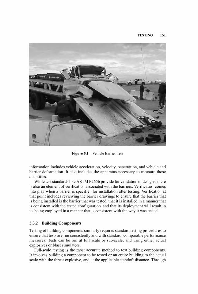
TESTING 151
Figure 5.1 Vehicle Barrier Test
information includes vehicle acceleration, velocity, penetration, and vehicle andbarrier deformation. It also includes the apparatus necessary to measure thosequantities.
While test standards like ASTM F2656 provide for validation of designs, thereis also an element of verificatio associated with the barriers. Verificatio comesinto play when a barrier is specifie for installation after testing. Verificatio atthat point includes reviewing the barrier drawings to ensure that the barrier thatis being installed is the barrier that was tested, that it is installed in a manner thatis consistent with the tested configuration and that its deployment will result inits being employed in a manner that is consistent with the way it was tested.
5.3.2 Building Components
Testing of building components similarly requires standard testing procedures toensure that tests are run consistently and with standard, comparable performancemeasures. Tests can be run at full scale or sub-scale, and using either actualexplosives or blast simulators.
Full-scale testing is the most accurate method to test building components.It involves building a component to be tested or an entire building to the actualscale with the threat explosive, and at the applicable standoff distance. Through
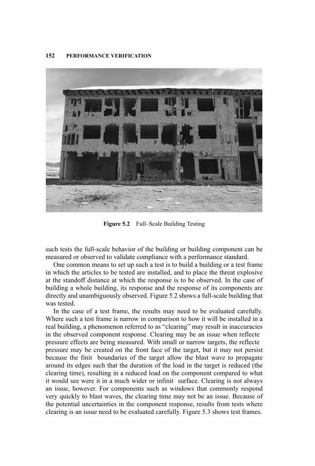
152 PERFORMANCE VERIFICATION
Figure 5.2 Full–Scale Building Testing
such tests the full-scale behavior of the building or building component can bemeasured or observed to validate compliance with a performance standard.
One common means to set up such a test is to build a building or a test framein which the articles to be tested are installed, and to place the threat explosiveat the standoff distance at which the response is to be observed. In the case ofbuilding a whole building, its response and the response of its components aredirectly and unambiguously observed. Figure 5.2 shows a full-scale building thatwas tested.
In the case of a test frame, the results may need to be evaluated carefully.Where such a test frame is narrow in comparison to how it will be installed in areal building, a phenomenon referred to as “clearing” may result in inaccuraciesin the observed component response. Clearing may be an issue when reflectepressure effects are being measured. With small or narrow targets, the reflectepressure may be created on the front face of the target, but it may not persistbecause the finit boundaries of the target allow the blast wave to propagatearound its edges such that the duration of the load in the target is reduced (theclearing time), resulting in a reduced load on the component compared to whatit would see were it in a much wider or infinit surface. Clearing is not alwaysan issue, however. For components such as windows that commonly respondvery quickly to blast waves, the clearing time may not be an issue. Because ofthe potential uncertainties in the component response, results from tests whereclearing is an issue need to be evaluated carefully. Figure 5.3 shows test frames.
TESTING 153
Figure 5.3 Test Frames in Arena Configuratio
Full-scale testing is often done in what is referred to as an arena test, as shownin Figure 5.3. In such a test, a number of test objects or test cells or framesare placed around a test explosive in roughly a circular pattern. Different testspecimens may be at different standoff distances from the explosive, allowingmultiple results from the same test.
Sub-scale testing involves reducing the scale of dimensions associated withthe test, including the test specimen, the distance from the explosive to the testspecimen, and the explosive itself. In those tests, dynamic similitude must bemaintained, which for explosives is done according to what is called Hopkinsonscaling. In Hopkinson scaling, quantities are scaled in proportion to the cube rootof the explosive weight. By scaling, similar blast phenomena can be observedwith smaller explosives at closer distances. For example, refer to Table 5.1 below,which shows the pressures and impulses for two different explosive weights attwo different standoff distances.
Note that the scaled range (standoff distance / the cube root of the explo-sive weight) is the same for both tests and that the pressures are the same. Thatshows that a test can be run for one explosive weight and can then be scaled up-ward or downward to reflec the effects of different explosive weights at differentdistances. This is a common practice in the blast community. Similarly, other di-mensions such as wall heights can be scaled, allowing a wide range of options inscaled modeling and testing.
It is important to note, however, that not all quantities scale alike. Note thatthe impulses associated with the two equivalent pressures are not the same. Thisillustrates why scaled testing has to be evaluated and verifie carefully. Whilesuch a pair of tests as those in Table 5.1 may be valid for components that are
Table 5.1 Hopkinson Scaled Pressures and Impulses
Quantity Test #1 Test #2
Weight (W) 1000 lbs TNT 220 lbs TNTRange (standoff distance) 100 ft 60.4 ftScaled range (Range / W1/3) 10 10W 1/3 10 lb 1/3 6.04 lb 1/3
Pressure 9.56 psi 9.56 psiImpulse 80.9 psi-msec 48.7 psi-msec
154 PERFORMANCE VERIFICATION
most responsive to peak pressures, they may not be valid for components that aremore responsive to impulse.
In either full-scale or sub-scale testing, the phenomena that are to be observedneed to be measured carefully and accurately. Most importantly, it is imperativethat the measurements that best reflec the response to be observed are measured.In all cases the basic geometry of the test needs to be recorded accurately, whichincludes the dimensions and construction of the test subject, how it installed intothe test cell or target building, the construction of the test cell or building, thesize and composition of the explosive, and the distance and angle of incidencefrom the explosive to the target. In addition, atmospheric conditions such as tem-perature, humidity, altitude, and wind speed and direction must be recorded.
In measuring test results, there are many measurements that a test reportshould include, depending on the nature of the test. Very importantly, the blastwave must be fully characterized using pressure gages and similar measuringdevices. Then the test specimen response parameters must be measured. Thosemeasurements depend on the response to be observed. If the member is intendedto remain intact with either elastic or inelastic deformation, the deflectio of themember must be measured. That will allow for calculation of support rotationsor ductility ratios (see Chapter 3). Those are commonly measured using straingages or displacement transducers.
If the response is expected to include failure of the test specimen with someexpected hazard level of the resulting fragments, additional measurements wouldbe required. Those would include measuring the sizes, weights, and translationsof the fragments, and their accelerations. Measuring devices for those includeaccelerometers and high-speed digital cameras. Figure 5.4 shows a setup for bothhigh-speed digital camera recording and deflection The camera cannot be seen,but the stripes painted in the wall allow for accurate evaluation of the velocitiesof the fragments.
Another option for measuring blast response of components is to use a blastsimulator. The most common blast simulators are tubes into which test speci-mens are mounted at one end. The blast simulating “driver” is at the end of thetube opposite the test specimen, and it commonly drives air into the test specimenat high velocities that simulate a blast wave. The measurements of the responsesof the test specimens are similar to those in open-air tests. Tests in blast simula-tors can usually be done much less expensively and in much quicker progressionthan open-air blast tests, and they can be operated in areas with far fewer restric-tions than those in which open-air blasts tests are run. It is important to recognize,however, that the blast simulator loadings should be validated against open-airtests to ensure that the loadings are representative of actual conditions. Figure5.5 shows a shock tube blast simulator with a wall specimen installed into it
There are few test standards for blast testing, but two commonly used stan-dards are ASTM test standards for doors and windows. ASTM F1642, Glazingand Glazing Systems Subject to Airblast Loadings, is described in Chapter 10.It describes test setup, test execution, and performance standards for windowssubjected to blast loads or simulated blast loads. ASTM F2247, Standard Test
TESTING 155
Figure 5.4 Digital Photography and Deflectio Measurement
Figure 5.5 Shock Tube Blast Simulator
156 PERFORMANCE VERIFICATION
Method for Metal Doors Used in Blast Resistant Applications, provides similarstandards for doors.
It is very important that test results undergo rigid verification which includesboth validation against other test results and evaluating test reports. The latter isparticularly important. Somebody who understands test reports should carefullyreview all of the conditions under which the tests were run, how the measure-ments were made, and how the test specimen responded. He or she must ensurethat the test was run in a valid manner and that the results are meaningful. In ad-dition to evaluating the conduct and setup of the test, he or she must also verifythat the results are valid based on issues such as accuracy of the loading, whetherscaling was taken into effect correctly, and whether clearing was an issue or wasaccounted for. This is less difficul for tests that are conducted in accordance witha particular standard, but those tests must also be evaluated carefully. In manyways explosive testing is more of an art than a science.
5.4 ANALYSIS
There are many ways to analyze the response of building elements to blastshocks, ranging from approximations to highly detailed analyses such as finitelement analysis, and for each of those there are multiple computer codes forperforming that analysis. There are also hand methods and charts. Analysis isthe least expensive means for evaluating performance, but because of the nonlin-earity of such analyses and the uncertainties in the loadings, dynamic materialproperties, and dynamic structural response, analyses require stringent verification and validation.
Verificatio includes evaluating the applicability of specifi methods to indi-vidual situations and ensuring that the models are applied correctly. Dependingon the assumptions upon which models are based, they may have limited applica-bility. Optimally, the applicability should be verifie before they are applied, butif not, their applicability must be verifie in evaluating the results of the analyses.
While the applicability of a model to a given situation needs to be verifiedit is at least as important that models be validated. Models can be validated bycomparing their results to the results of other models that have been validatedfor identical situations. For example, a computer code to be validated can beused to analyze a beam, a wall, a window, or any other building componentof a specifi geometry and configuration and those results can be compared tothose derived by using a previously validated code. This is particularly the casewith finit element analyses, where there are so many variables that have to beconsidered in the models that results can appear reasonable, but turn out to befallacious.
Results can also be compared to test results, which can serve as benchmarks.In either case, validation gives the user both confidenc in the model and con-fidenc that its application is reasonable for that situation. This is particularlyuseful for finit element models.

REFERENCES 157
In addition to analyzing buildings and building components to blast loads,there are models for analyzing vehicle barriers. Because they model suchcomplex situations as vehicle–structure interaction, structural response, andsoil–structure interaction, those models tend to be very complicated. They of-ten include finit element analysis models. Because they’re so complicated, itis especially important that they be validated. Usually that validation is doneby either comparing them to existing test results or performing testing after theanalysis to validate the analysis results. The most common use of analysis mod-els for vehicle barriers, therefore, is to design the barriers and validate the resultsthrough testing.
5.5 PEER REVIEW
Because analysis and testing for blast loads involve such complexity, it is veryimportant that test results and analyses be validated through peer review. Peerreview is particularly important for structures with unique structural features orstructures that have high importance or high economic value.
In addition, because the number of experienced blast consultants is still lim-ited, peer review is particularly important where analysis is done by less experi-enced designers.
Verificatio and validation through peer review can take multiple forms. As aminimum, it should include detailed review of drawings to ensure that details areconsistent with the assumptions in the design analyses and that the drawingsareproperly detailed, to allow the expected performance to be achieved. Verificatioshould also evaluate the applicability of the models used and the accuracy withwhich they were applied. It should also include checks of at least major elementsof the design calculations.
Peer review should be done by people who have significan experience inapplying the models used for the applications on which they were applied.
REFERENCES
ASTM. 2003. Standard Test Method for Metal Doors Used in Blast Resistant Applica-tions (F2247). West Conshohocken, PA: ASTM International.
. 2004. Glazing and Glazing Systems Subject to Airblast Loadings (F1642).West Conshohocken, PA: ASTM International.
. 2007. Vehicle Crash Testing of Perimeter Barriers (F2656). West Con-shohocken, PA: ASTM International.

II Blast Phenomena and Loadings
Handbook for Blast-Resistant Design of Buildings Edited by Donald 0. Dusenberry
Copyright 0 2010 by John Wiley & Sons, Inc. All rights reserved.

6 Blast Phenomena
Paul F. Mlakar and Darrell Barker
6.1 INTRODUCTION
Blast is a pressure disturbance caused by the sudden release of energy. Peopleoften think of blasts in terms of explosions such as the detonation of an explosivecharge. However, there are many other blast sources that have the potential tocause damage. For example, chemicals may undergo a rapid decomposition un-der certain conditions. These events are often referred to as runaway reactions.Flammable materials mixed with air can form vapor clouds that when ignitedcan cause very large blasts. Blasts are not always caused by combustion; theycan also result from any rapid release of energy that creates a blast wave, such asa bursting pressure vessel from which compressed air expands, or a rapid phasetransition of a liquid to a gas.
The loads resulting from a blast are created by the rapid expansion of the ener-getic material, creating a pressure disturbance or blast wave radiating away fromthe explosion source, as shown in Figure 6.1. Blast pressure is more properlyoverpressure, because it is relative to ambient conditions, rather than an absolutepressure. Shock waves are high-pressure blast waves that travel through air (oranother medium) at a velocity faster than the speed of sound. Shock waves arecharacterized by an instantaneous increase in pressure followed by a rapid de-cay. Pressure waves are lower amplitude and travel below the speed of sound.Pressure waves are characterized by a more gradual increase in pressure than ashock wave, with a decay of pressure much slower than a shock wave. In mostcases, shock waves have a greater potential for damage and injury than pressurewaves.
As a blast wave travels away from the source, the pressure amplitude de-creases, and the duration of the blast load increases. Overexpansion at the centerof the blast creates a vacuum in the source region and a reversal of gas mo-tion. This negative pressure region expands outward, causing a negative pressure(below ambient), which trails the positive phase. The negative phase pressureis generally lower in magnitude (absolute value) but longer in duration than thepositive phase. Generally speaking, positive phase blast loads are more conse-quential than negative phase loads, the latter of which is often ignored.
161
Handbook for Blast-Resistant Design of Buildings Edited by Donald 0. Dusenberry
Copyright 0 2010 by John Wiley & Sons, Inc. All rights reserved.
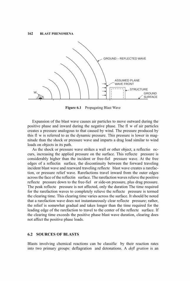
162 BLAST PHENOMENA
GROUND – REFLECTED WAVE
W
ASSUMED PLANEWAVE FRONT
STRUCTUREGROUND SURFACE
Figure 6.1 Propagating Blast Wave
Expansion of the blast wave causes air particles to move outward during thepositive phase and inward during the negative phase. The fl w of air particlescreates a pressure analogous to that caused by wind. The pressure produced bythis fl w is referred to as the dynamic pressure. This pressure is lower in mag-nitude than the shock or pressure wave and imparts a drag load similar to windloads on objects in its path.
As the shock or pressure wave strikes a wall or other object, a reflectio oc-curs, increasing the applied pressure on the surface. This reflecte pressure isconsiderably higher than the incident or free-fiel pressure wave. At the freeedges of a reflectin surface, the discontinuity between the forward travelingincident blast wave and rearward traveling reflecte blast wave creates a rarefac-tion, or pressure relief wave. Rarefactions travel inward from the outer edgesacross the face of the reflectin surface. The rarefaction waves relieve the positivereflecte pressure down to the free-fiel or side-on pressure, plus drag pressure.The peak reflecte pressure is not affected, only the duration The time requiredfor the rarefaction waves to completely relieve the reflecte pressure is termedthe clearing time. This clearing time varies across the surface. It should be notedthat a rarefaction wave does not instantaneously clear reflecte pressure; rather,the relief is somewhat gradual and takes longer than the time required for theleading edge of the rarefaction to travel to the center of the reflecte surface. Ifthe clearing time exceeds the positive phase blast wave duration, clearing doesnot affect the positive phase loads.
6.2 SOURCES OF BLASTS
Blasts involving chemical reactions can be classifie by their reaction ratesinto two primary groups: deflagration and detonations. A defl gration is an
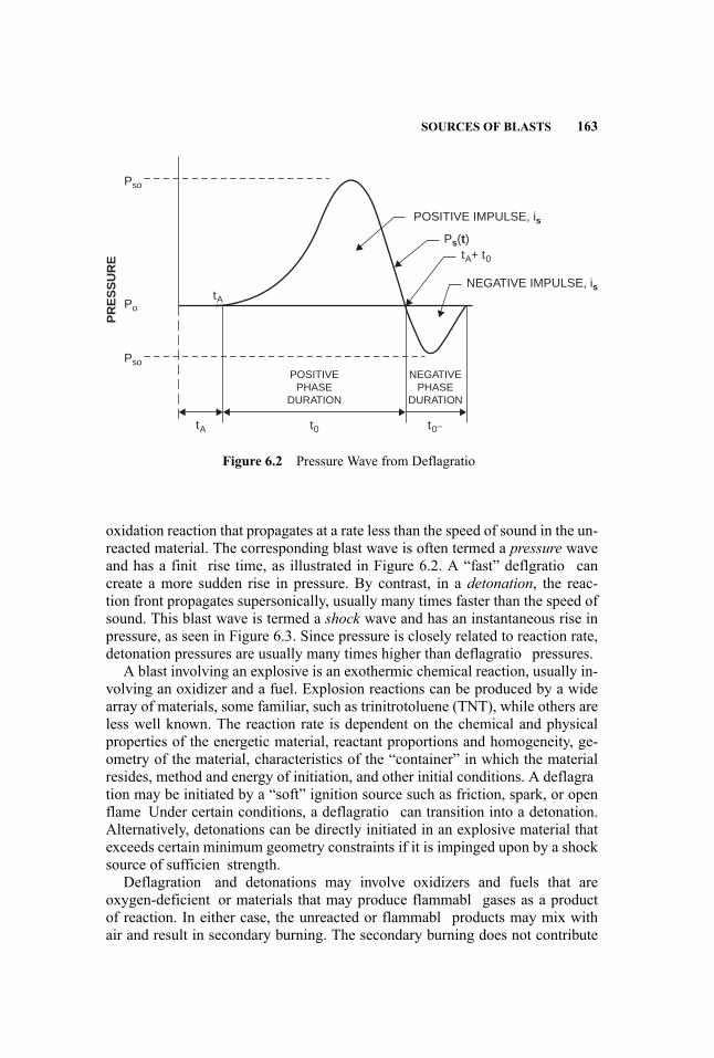
SOURCES OF BLASTS 163
POSITIVE IMPULSE, is
NEGATIVE IMPULSE, is
Ps(t)tA+ t0
POSITIVEPHASE
DURATION
NEGATIVEPHASE
DURATION
t0tA
tA
t0–
Pso
Po
Pso
PR
ES
SU
RE
Figure 6.2 Pressure Wave from Deflagratio
oxidation reaction that propagates at a rate less than the speed of sound in the un-reacted material. The corresponding blast wave is often termed a pressure waveand has a finit rise time, as illustrated in Figure 6.2. A “fast” deflgratio cancreate a more sudden rise in pressure. By contrast, in a detonation, the reac-tion front propagates supersonically, usually many times faster than the speed ofsound. This blast wave is termed a shock wave and has an instantaneous rise inpressure, as seen in Figure 6.3. Since pressure is closely related to reaction rate,detonation pressures are usually many times higher than deflagratio pressures.
A blast involving an explosive is an exothermic chemical reaction, usually in-volving an oxidizer and a fuel. Explosion reactions can be produced by a widearray of materials, some familiar, such as trinitrotoluene (TNT), while others areless well known. The reaction rate is dependent on the chemical and physicalproperties of the energetic material, reactant proportions and homogeneity, ge-ometry of the material, characteristics of the “container” in which the materialresides, method and energy of initiation, and other initial conditions. A deflagration may be initiated by a “soft” ignition source such as friction, spark, or openflame Under certain conditions, a deflagratio can transition into a detonation.Alternatively, detonations can be directly initiated in an explosive material thatexceeds certain minimum geometry constraints if it is impinged upon by a shocksource of sufficien strength.
Deflagration and detonations may involve oxidizers and fuels that areoxygen-deficient or materials that may produce flammabl gases as a productof reaction. In either case, the unreacted or flammabl products may mix withair and result in secondary burning. The secondary burning does not contribute
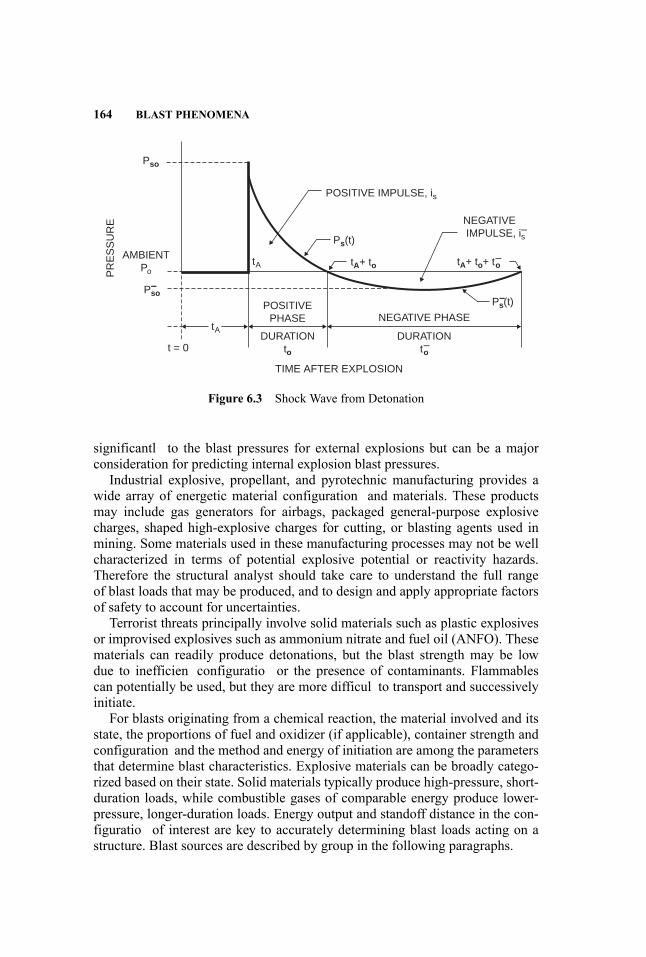
164 BLAST PHENOMENA
POSITIVE IMPULSE, is
POSITIVEPHASE NEGATIVE PHASE
TIME AFTER EXPLOSION
DURATIONto
DURATIONt–o
NEGATIVE IMPULSE, i–sPs(t)
P–s(t)
Pso
AMBIENTPoP
RE
SS
UR
E
P–so
tA+ to
tA
t = 0
tA tA+ to+ t–o
Figure 6.3 Shock Wave from Detonation
significantl to the blast pressures for external explosions but can be a majorconsideration for predicting internal explosion blast pressures.
Industrial explosive, propellant, and pyrotechnic manufacturing provides awide array of energetic material configuration and materials. These productsmay include gas generators for airbags, packaged general-purpose explosivecharges, shaped high-explosive charges for cutting, or blasting agents used inmining. Some materials used in these manufacturing processes may not be wellcharacterized in terms of potential explosive potential or reactivity hazards.Therefore the structural analyst should take care to understand the full rangeof blast loads that may be produced, and to design and apply appropriate factorsof safety to account for uncertainties.
Terrorist threats principally involve solid materials such as plastic explosivesor improvised explosives such as ammonium nitrate and fuel oil (ANFO). Thesematerials can readily produce detonations, but the blast strength may be lowdue to inefficien configuratio or the presence of contaminants. Flammablescan potentially be used, but they are more difficul to transport and successivelyinitiate.
For blasts originating from a chemical reaction, the material involved and itsstate, the proportions of fuel and oxidizer (if applicable), container strength andconfiguration and the method and energy of initiation are among the parametersthat determine blast characteristics. Explosive materials can be broadly catego-rized based on their state. Solid materials typically produce high-pressure, short-duration loads, while combustible gases of comparable energy produce lower-pressure, longer-duration loads. Energy output and standoff distance in the con-figuratio of interest are key to accurately determining blast loads acting on astructure. Blast sources are described by group in the following paragraphs.

SOURCES OF BLASTS 165
High explosives are materials that are intended to produce detonation eventswith supersonic reaction fronts. The reactions proceeding through the explosiveare self-sustaining if the charge is of sufficien diameter and properly initiated.Reaction rate, or detonation velocity, varies with material type and is a key fac-tor in detonation pressure for a material. Detonation velocities typically rangefrom 3000 to 30,000 ft/s (1–9 km/s). High explosives can be classifie by theirsensitivity to initiation into primary, secondary, and tertiary explosives. Primaryexplosives are very sensitive to initiation—for example, lead azide used in deto-nators. Secondary high explosives include TNT, composition C4, and dynamite.Tertiary explosives are much less sensitive to initiation and require a powerfulbooster charge to initiate them. The blasting agent ANFO is an example of atertiary explosive.
For convenience in predicting blast pressures, the energy release of high ex-plosives is commonly measured as a value relative to that of TNT. This “TNTequivalence” is used to determine a TNT charge weight capable of producing thesame explosion energy, blast pressure, or blast impulse as the explosive of inter-est. The TNT equivalence is different for energy, peak pressure, and impulse, andseparate TNT equivalent energy values are reported for many materials. Equiva-lencies for a number of these materials appear in Table 6.1.
High-explosive detonations may be accidental or intentional events. Accidentsinvolving high explosives can occur in processing, handling, and transportation.Intentional detonations can include explosives testing, military weapons, demo-lition, specialized cutting or explosive forming, and terrorist acts. In the case ofintentional detonations, structures, such as test structures, may be required towithstand multiple events.
Confine explosive charges will create gas pressures in the structure in addi-tion to shock waves. If the structure is not adequately vented, the effects of thesegas pressure loads may exceed those of the shock loads.
High explosives come in many forms determined by their chemical and physi-cal properties and intended use. Most explosives have additives to aid in stabiliz-ing the material chemically or physically. Powdered explosives may be combinedwith a plastic binder to form plastic-bonded or PBX explosive. Extrudable ex-plosives have a viscous form due to the addition of rubber resins to the explosivematerial. This addition allows the explosive to be molded or extruded to producea particular shape.
Certain liquids, such as nitromethane, can also detonate. Nitromethane is rel-atively insensitive and must be initiated by a strong ignition source such as ahigh-explosive booster. It does have safety advantages over other materials andmay be handled as a simple flammabl liquid in many cases. The shock frontproduced by nitromethane is well formed and produces blast loads with approx-imately 100% TNT equivalence.Propellants and pyrotechnics, also known as low explosives, are energetic ma-
terials that do not typically detonate and are used to produce gas, smoke, flashor sound. Both solid and liquid rocket propellants, gun propellants, and blackpowder are examples of low explosives. Pyrotechnics include many different
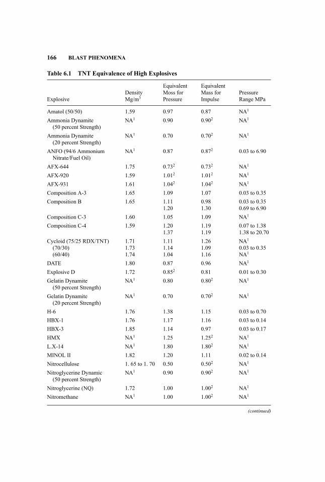
166 BLAST PHENOMENA
Table 6.1 TNT Equivalence of High Explosives
ExplosiveDensityMg/m3
EquivalentMoss forPressure
EquivalentMass forImpulse
PressureRange MPa
Amatol (50/50) 1.59 0.97 0.87 NA1
Ammonia Dynamite(50 percent Strength)
NA1 0.90 0.902 NA1
Ammonia Dynamite(20 percent Strength)
NA1 0.70 0.702 NA1
ANFO (94/6 AmmoniumNitrate/Fuel Oil)
NA1 0.87 0.872 0.03 to 6.90
AFX-644 1.75 0.732 0.732 NA1
AFX-920 1.59 1.012 1.012 NA1
AFX-931 1.61 1.042 1.042 NA1
Composition A-3 1.65 1.09 1.07 0.03 to 0.35Composition B 1.65 1.11
1.200.981.30
0.03 to 0.350.69 to 6.90
Composition C-3 1.60 1.05 1.09 NA1
Composition C-4 1.59 1.201.37
1.191.19
0.07 to 1.381.38 to 20.70
Cycloid (75/25 RDX/TNT)(70/30)(60/40)
1.711.731.74
1.111.141.04
1.261.091.16
NA1
0.03 to 0.35NA1
DATE 1.80 0.87 0.96 NA1
Explosive D 1.72 0.852 0.81 0.01 to 0.30Gelatin Dynamite(50 percent Strength)
NA1 0.80 0.802 NA1
Gelatin Dynamite(20 percent Strength)
NA1 0.70 0.702 NA1
H-6 1.76 1.38 1.15 0.03 to 0.70HBX-1 1.76 1.17 1.16 0.03 to 0.14HBX-3 1.85 1.14 0.97 0.03 to 0.17HMX NA1 1.25 1.252 NA1
L.X-14 NA1 1.80 1.802 NA1
MINOL II 1.82 1.20 1.11 0.02 to 0.14Nitrocellulose 1. 65 to 1. 70 0.50 0.502 NA1
Nitroglycerine Dynamic(50 percent Strength)
NA1 0.90 0.902 NA1
Nitroglycerine (NQ) 1.72 1.00 1.002 NA1
Nitromethane NA1 1.00 1.002 NA1
(continued)

SOURCES OF BLASTS 167
Table 6.1 (Continued)
ExplosiveDensityMg/m3
EquivalentMoss forPressure
EquivalentMass forImpulse
PressureRange MPa
Octol (75/25 HMX/TNT)(70/30)
1.811.14
1.021.09
1.061.092
NA1
0.01 to 0.30PBX-9010 1.80 1.29 1.292 0.03 to 0.21PBX-9404 1.81 1.13
1.701.1321.70
0.03 to 0.690.69 to 6.90
PBX-9502 1.89 1.00 1.00 NA1
PBXC-129 1.71 1.10 1.102 NA1
PBXN-4 1.71 0.83 0.85 NA1
PBXN-107 1.64 1.052 1.052 NA1
PBXN-109 1.67 1.052 1.052 NA1
PBXW-9 NA1 1.30 1.302 NA1
PBXW-125 1.80 1.022 1.022 NA1
Pentolite. (Cast) 1.641.68NA1
1.421.381.50
1.001.141.00
0.03 to 0.690.03 to 4.140.69 to 6.90
PETN 1.77 1.27 1.272 0.03 to 0.69Picroto1 (52/48 Ex D/TNT) 1.63 0.90 0.93 0.03 to 4.10RDX NA1 1.10 1.102 NA1
RDX/Wax (98/2) 1.92 1.16 1.162 NA1
RDX/AL/Wax (74/21/5) NA1 1.30 1.302 NA1
TATB NA1 1.00 1.002 NA1
Tetryl 1.73 1.07 1.072 0. 02 to 0.14Tetrytol (75/25 Tetryl/TNT) 1.59 1.06 1.062 NA1
TNETB 1.69 1.13 0.96 0.03 to 0.69TNETB/AL (90/10)
(78/22)(65/35)
1.751.18123
1.231.321.38
1.111.3221.382
0.03 to 0.69NA1
NA1
TNT 1.63 1.00 1.00 StandardTorpex 1.85 1.23 1.28 0.01 to 0.30Tritonal (80/20 TNT/AL) 1.72 1.07 0.96 0.03 to 0.69
1NA - Data not available.2Value is estimated.
materials such as fir works, smoke grenades, flares and the gas generator mate-rial in automobile air bags. The relatively low reaction rates of these materialsresult in low blast pressure output because they typically don’t detonate. Firehazards and gas generation concerns dominate the safety analysis in most cases,but detonations or deflagration cannot be ruled out in all cases.

168 BLAST PHENOMENA
Figure 6.4 Vapor Cloud Explosion in 9/11 Pentagon Crash
Predicting blast loads for these materials can be challenging. There is muchless data available for propellants and pyrotechnics than for high explosives, withrespect to blast loads. Burn rates, gas generation, and energy output rates areavailable in handbooks for common propellants (Cooper and Kurowsky 1996)These values can be used to perform a burn simulation and determine the gaspressure load in a confine area. In some cases, TNT equivalencies for thesematerials have been used. However, this is problematic because peak pressurefor propellants and pyrotechnics is much lower than for TNT, but the impulseof propellents can be higher in a confine space than for the TNT equivalent.Care must be taken when equivalencies are based on small-scale tests, as largequantities may react in a more energetic manner.Vapor cloud explosions involve the release of a flammabl material which,
when mixed with air and given the proper conditions, forms an ignitable mate-rial, potentially leading to an explosion. The vapor cloud explosion following the9/11 Pentagon crash is shown in Figure 6.4. Only fuel within flammabilit limitsparticipates in the explosion, which is a minor percentage of the total quantity offuel released (Baker et al. 1991). Much of the fuel vapor is too lean or too rich tocombust and does not produce blast overpressure. Blast output of a vapor cloudexplosion is highly variable and depends on the fuel, size of the flammabl va-por cloud, presence of congestion (obstacles such as structural members, pipes,and vessels) in the flammabl region, and presence of confinin surfaces. Re-lease of a flammabl material into the open air, absent congestion or confinement, typically results in a firebal that does not produce damaging overpressures.

SOURCES OF BLASTS 169
Confinemen and congestion in the flammabl cloud create turbulence and accel-erate the combustion, thereby increasing the flam speed. Peak overpressure isa strong function of flam speed; thus, a key element in vapor cloud explosionprediction is maximum flam speed. Vapor cloud detonations are rare and onlyknown to occur with high-reactivity materials, strong ignition sources, and/orsevere cases of confinemen and congestion. The vast majority of vapor cloudexplosions are deflagrations A particularly noteworthy characteristic of deflagrations is that high flam speeds only occur in confined/congeste regions ofthe flammabl cloud. Outside of congested areas, flam speed decreases. As aresult, deflagratio blast loads are produced in confined/congeste areas, ratherthan at the point of release or dispersion. In the rare case of vapor cloud detona-tions, the blast loads are produced by the detonatable material and are typicallyconsidered to be centered in the dispersed cloud and not at the point of release.
Overpressures produced by vapor cloud explosions are substantially lowerthan those produced by high explosives. For example, a vapor cloud detona-tion may reach 16–18 atmospheres overpressure, compared with 100,000 atmo-spheres or greater for most high explosives. However, the energy of vapor cloudexplosions can be very large, as evidenced by some of the devastating accidentswhich have occurred. In Flixborough, U.K., a 30,000-kg release of cyclohexanecaused an explosion that resulted in 28 fatalities, multiple injuries, and destruc-tion of more than 150 structures. The large energy in hydrocarbons produces acommensurately large impulse. Blast predictions made using a TNT equivalentapproach tend to be inaccurate due to the disparity between the pressure andimpulse compared with high explosives. As a result, TNT equivalence analysesof vapor cloud explosions are not recommended. A more accurate method is toperform a dispersion analysis of the flammabl release to determine fuel in theflammabilit limits, select appropriate speed or reaction severity, then use nondi-mensional scaled energy curves to determine the pressure and impulse at vari-ous standoff distances. Computational flui dynamics (CFD) analysis is anothermethod of determining blast pressures for vapor releases.
Vessels designed to contain fluid under pressure have the potential to createhazardous overpressures and fragments if the vessel fails while under pressure. Apressure vessel burst may occur at normal working pressure due to a mechanicalintegrity problem, weakening, or other external factors (such as impact); or atelevated pressure due to excessive pressurization from an external source, anuncontrolled internal chemical reaction, heating vessel contents with insufficienpressure relief, or other means. This type of accident results in loss of contentsand may lead to a follow-on explosion when the contents subsequently mix withair, if the contents are flammabl or pyrophoric.
In the far field the blast load from a vessel that fails at high pressures (severalthousand psi [1000 psi = 6895 kPa] or higher) is similar to that caused by highexplosives. In the near field overpressures are less than those produced by highexplosives, and the use of TNT equivalent prediction procedures will overesti-mate pressure. Key parameters for estimating blast effects from bursting vessels

170 BLAST PHENOMENA
are the volume of the material in the vessel, the failure pressure, the compositionof the contents, and the temperature of the contents.
Fragments represent an additional hazard from bursting vessels. Failure atworking pressure or overpressurization at a relatively slow rate usually resultsin a small number of fairly large fragments. In some cases, one or both endsof a cylindrical pressure vessel may be propelled long distances by a rocketingmechanism. Large fragments may be thrown as a result of the expansion of thevessel contents. Containment of these fragments, which can be quite challenging,may be required to provide adequate safety. Fragment hazard prediction methodsare discussed further in Chapter 8 of this handbook.
A boiling liquid expanding vapor explosion (BLEVE) occurs when a vesselcontaining a liquid stored above its boiling point for atmospheric pressure failsand a rapid depressurization of the liquid occurs. Upon depressurization, a por-tion of the superheated liquid rapidly boils, and the expanding vapors contributeto the blast wave. Compressed gases in the vessel prior to failure also contributeto the blast wave as in a bursting pressure vessel. A common BLEVE scenariois a pressure vessel engulfed in an extended fire causing weakening of the ves-sel shell to the point of failure. A BLEVE may involve a flammabl liquid, andmixing of the flammabl material with air and subsequent ignition may cause afireball A detailed discussion of BLEVE events and of simplifie blast predic-tion methods is provided in CCPS’s Guidelines for Evaluating the Characteris-tics of Vapor Cloud Explosions, Flash Fires, and BLEVES (Center for ChemicalProcess Safety 1994).
6.3 CHARACTERISTICS OF BLAST WAVES
6.3.1 Key Parameters
An idealized pressure-time history indicating the key parameters of a blast load isshown in Figure 6.3. Figure 6.5 shows a comparison between free-field or side-on, and reflecte pressure-time histories. The parameters shown in these figureare define as:
Po = Ambient pressurePso = Peak positive side-on overpressureP−so = Peak negative side-on overpressurePs(t) = Time varying positive overpressureP−s (t) = Time varying negative overpressurePr = Peak reflecte overpressureIs = Positive-phase-specifi impulse, the integration of the positive
phase pressure-time historyi−s = Negative-phase-specifi impulse, the integration of the negative
phase pressure-time history
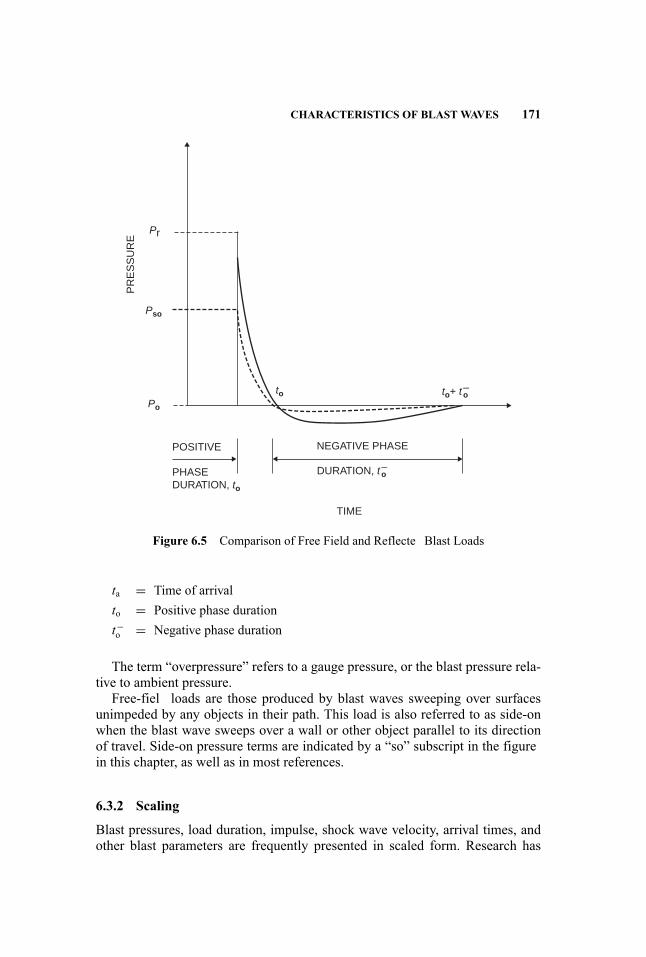
CHARACTERISTICS OF BLAST WAVES 171
Pso
Po
to
Pr
PR
ES
SU
RE
to+ t–o
NEGATIVE PHASE
DURATION, t–oPHASEDURATION, to
POSITIVE
TIME
Figure 6.5 Comparison of Free Field and Reflecte Blast Loads
ta = Time of arrivalto = Positive phase durationt−o = Negative phase duration
The term “overpressure” refers to a gauge pressure, or the blast pressure rela-tive to ambient pressure.
Free-fiel loads are those produced by blast waves sweeping over surfacesunimpeded by any objects in their path. This load is also referred to as side-onwhen the blast wave sweeps over a wall or other object parallel to its directionof travel. Side-on pressure terms are indicated by a “so” subscript in the figurein this chapter, as well as in most references.
6.3.2 Scaling
Blast pressures, load duration, impulse, shock wave velocity, arrival times, andother blast parameters are frequently presented in scaled form. Research has
172 BLAST PHENOMENA
shown that scaling laws can be applied to explosions, allowing data from oneexplosion test to be applied to a geometrically similar (larger or smaller) case.As a result, scaling has tremendous utility in blast predictions, allowing compi-lations of explosion test and numerical modeling data to be used to predict loadsfor any combination of explosion energy and standoff distance within the rangeof data. The most common form of scaling is called “cube root scaling” owing tothe fact that blast parameters are scaled by the cube root of the explosion energy.Both dimensional and dimensionless scaling are used, and care must be takenwith all unit parameters to ensure the scaling is correctly applied for the blastcurves being used.
6.4 PREDICTION OF BLAST PARAMETERS
This section describes the principal methods for predicting blast parameters, withsome discussion of practical applications and limitations. A more detailed treat-ment is given for high explosives and vapor cloud explosions because these tendto be the most common design threats for protective construction. Definitio ofthe blast hazard is discussed in Chapter 2, and calculation of the loads imposedon the structure in Chapter 7.
In many cases, blast load prediction is a multi-step process. Often an initialestimate of blast loads will be made using simplifie techniques and a conser-vative estimate of explosion energy. It may become obvious at this point thatthe predicted loads are so low they are not a contributing factor in structural de-sign, or will not cause undue cost or complexity in the design. Thus, the initialloads are judged to be adequate for analysis or design. If loads are high enoughto drive the design, it may be appropriate to perform a more detailed blast loadprediction which uses less conservative estimates of energy and more detailedprediction techniques.
The basic simplifie approach involves predicting free-fiel loads using em-pirical or semi-empirical methods. Blast curves that relate explosion energy,standoff distance, and blast wave parameters are typically used in this initialload-prediction step. These curves are readily available for high explosives andvapor cloud explosions.
6.4.1 High Explosives
A significan amount of data has been produced that quantifie the relationshipsamong charge weight, standoff distance, and blast parameters for both positiveand negative phases. A Unifie Facilities Criteria publication, Structures to Re-sist the Effects of Accidental Explosions, produced by the Department of De-fense, contains the relationships in the form of scaled blast curves (U.S. Depart-ment of Defense 2008). This document is publicly available, and an electronicversion also exists to aid in the use of the numerous tables and figures

PREDICTION OF BLAST PARAMETERS 173
The empirical blast parameter curves provided in this document plot air-blastparameters versus scaled distance for both air-burst and surface-burst configurations. A charge detonated on the ground will produce higher blast loads than anair burst due to the reflectio of the shock by the ground surface. For unyield-ing surfaces with the charge located on the surface, the effect is a doubling ofthe charge weight, since the energy of the blast directed to the ground is fullyreflected For soft soils or charges located above the surface, the reflectio factoris less than two, since some of the energy is absorbed by the substrate. Someguidance for selecting the reflectio factor is given in the document, but it isconservative to assume a fully reflectin surface.
The most commonly used approach to present blast wave relationships forhigh explosives is the Hopkinson-Cranz, or cube root, scaling method. Figure 6.6is a simplifie version of TNT blast curves that provides the parameters forcharges located at ground level. The cube root term results from geometric scal-ing laws in which charge diameter varies in proportion to all distances, and thusthe charge weight is proportional to the cube of the charge diameter. To use theseempirical curves, one computes the scaled distance by dividing the standoff dis-tance from the charge to the point of interest by the cube root of the chargeweight. For explosives, this takes the form of
Z = R/W 1/3 where : (6.1)Z = scaled distance (ft/lb1/3)R = standoff distance (ft)W = explosives weight (lb)
The curves provide pressures, P, which are the same at a given scaled dis-tance. The curves also provide scaled times, t/W1/3, and scaled impulses, I/W1/3.The actual times and impulses are then found by multiplying the scaled valuesby W1/3.
In accordance with the common practice for blast design, the variables inEquation 6.1 and Figure 6.6 have physical dimensions. However the procedureis rigorously founded on dimensionless modeling. It is also based on atmo-spheric conditions at sea level. While this suffice for most practical situations,the effects of differing ambient conditions can be treated more comprehensivelythrough Sachs or energy scaling (Baker 1973).
As an example of cube root scaling, let us consider the Oklahoma City Bomb-ing. This event has been reported to have been equivalent to the detonation of4,000 lbs of TNT at essentially the ground surface. If a location of interest is100 ft away, the scaled distance is
Z = 100/(4000)1/3 = 6.30 ft/lb1/3
From Figure 6.6 we have an incident pressure of Po = 24.9 psi and a reflectepressure of Pr = 79.5 psi at this scaled range. This figur also provides the scaledpositive phase duration to/W1/3 = 1.77 msec/lb1/3. From this, the total positive
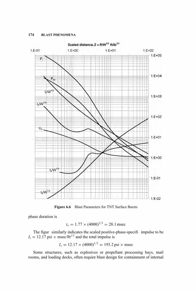
174 BLAST PHENOMENA
Figure 6.6 Blast Parameters for TNT Surface Bursts
phase duration is
to = 1.77× (4000)1/3 = 28.1msec
The figur similarly indicates the scaled positive-phase-specifi impulse to beIs = 12.17 psi × msec/lb1/3 and the total impulse is
Is = 12.17× (4000)1/3 = 193.2 psi×msec
Some structures, such as explosives or propellant processing bays, mailrooms, and loading docks, often require blast design for containment of internal

PREDICTION OF BLAST PARAMETERS 175
explosion effects. Containment designs must consider that shock waves emanatefrom the charge, strike wall and roof components, and reflec to impact othersurfaces. Each surface is subjected to multiple shock waves.
Internal explosions also produce gas and heat, which cause a pressure increasewithin the containment. The peak gas pressure, Pg, developed is a function ofthe charge weight/free volume ratio in the containment. This pressure buildup isrelatively slow compared to the load duration associated with shock waves. Forsimplicity, the peak gas or quasi-static pressure is assumed to rise instantaneouslyto the peak gas pressure but is not additive to shock pressures. A curve of peakgas pressuresversus weight/volume is shown in Figure 6.7.
For example, let us consider the detonation of W = 200 lbs of TNT withina structure having a free volume of Vf = 50,000 ft3. This loading density isW/Vf = 200/50,000 = 4 × 10⁻³ lb/ft3. From Figure 6.7 the peak gas pressure isPg = 47.2 psi.
The duration of the gas pressures is a function of the vent area available andthe rate at which temperature decays in the containment area. Vent area canchange over time, depending on how fast the vent cover moves away from theenclosure. The vent velocity is a function of the applied shock impulse and thefrangibility and mass of the vent cover. The duration is determined by firs com-puting the peak gas pressure from Figure 6.7. Then the gas impulse, Ig, is esti-mated from a set of graphs as a function of the scaled vent area, scaled mass ofthe vent cover, loading density, and scaled shock impulse (U.S. Department ofDefense 2008). An equivalent triangular gas duration is then
tg = 2Ig/Pg
Analytical methods have been developed to predict blast loads. These meth-ods fall into two groups: semi-empirical and hydrocode. The semi-empirical ap-proach utilizes a physics-based model to compute selected blast parameters withcoefficient that are “tuned” to match test data. These models are limited to con-figuration and charge weight ratios for which data are available, but offer theadvantage of quick run times compared with more detailed techniques. Semi-empirical codes may offer limited abilities to model shock diffraction, shield-ing, and reflection Semi-empirical methods have been developed primarily bydefense-related agencies and are restricted to distribution to the government andits contractors.
Hydrodynamic codes, or hydrocodes, utilize a grid of computational cells totrack detonation propagation through an explosive charge and shock wave prop-agation through a medium. Using principles of material behaviors, fundamen-tal thermodynamics, and flui dynamics, hydrocodes predict pressure, density,and other key parameters. This type of analysis is much more complex thanthe use of empirical relationships. Some of the available tools have user inter-faces that greatly simplify the analysis, especially for standard materials, butconsiderable effort and expertise are typically required to conduct a competentanalysis.

176 BLAST PHENOMENA
Figure 6.7 Peak Gas Pressure for Internal Detonations
The output from hydrocodes will be in the form of pressure-time series forselected locations in the model. Application of these loads to the structuralmodel can be tedious. If the structural analysis involves a time series calculation,the time varying loads may be transferred into the structural analysis, but thenumber of data points to be transferred may be excessive. Normally, a simplification is made to the applied load history to greatly reduce the number of loadpoints to a series of lines approximating the “real” curve. This reduced multi-point curve is more complex than the linear decay curve used for the empiricalrelationship analysis. A coupled analysis may be performed in the hydrocode

PREDICTION OF BLAST PARAMETERS 177
Figure 6.7 (Continued)
which models blast propagation and structural response. This approach offersadditional capability for detailed response analysis but with significan increasein complexity compared with simulation of blast loads alone.
6.4.2 Bursting Pressure Vessels
Bursting pressure vessel blast predictions are most commonly conducted in oneof two ways: simplifie analytical methods or computation flui dynamics (CFD)
178 BLAST PHENOMENA
models. In either case, it is necessary to select the conditions under which thevessel would be expected to fail—overpressure/overfilling runaway reaction, ex-ternal heating, mechanical or impact load, corrosion, or other mechanisms. Thisselection is important because it determines the composition, pressure, tempera-ture, phase, and energy of the vessel contents, all of which can have a significaneffect on the predicted blast loads. In any case, as long as the vessel pressureis above two atmospheres at failure and the pressure is released abruptly, theresultant blast will be a shock wave (i.e., suddenly applied).
The most recent simplifie method was published by Tang (Tang et al. 1996)and consists of a series of nondimensionalized curves to predict the side-on pres-sure and impulse at a particular standoff as a function of pressure ratio (defineas burst pressure divided by ambient pressure), ratio of specifi heats of the ves-sel contents (a property of the gaseous contents of the vessel), expansion energypotential of the vessel contents, and the temperature ratio (the ratio of the vesselinternal temperature at failure to the ambient temperature). The vessel energyterm in this analysis should be corrected for ground reflection liquid fraction inthe vessel, and energy consumed by fragment production. In addition, the side-on pressures need to be modifie to account for reflectio and clearing effects,as described in the next chapter.
If more detail is necessary, a CFD model can be applied. These consider thethermodynamics and gas properties to compute the production and propagationof blast waves produced by a bursting vessel. It is important to note that thereare complex interactions between the failing vessel and the flui escaping thevessel that cannot be adequately modeled by any publicly available current pro-gram. In addition, the failure of the vessel is not wholly deterministic, as crackscan propagate along micro-cracks and grain boundaries in a manner that cannotusually be predicted. As a result, these numerical analyses will rely heavily onthe experience and expertise of the analyst. The advantage of using a hydrocodeis that it can directly produce load-time distributions on arbitrary surfaces andaccount for shielding and focusing effects produced by adjacent structures.
6.4.3 Vapor Cloud Explosions
Prediction of blast loads for vapor cloud explosions can be more complex thanloads for high explosive detonations or bursting pressure vessels. The firs stepin determining blast load from vapor cloud explosions is to develop the releasescenario for the flammabl material. This selection process is typically done withinput from process engineers and plant operations. Dispersion modeling is per-formed to model the release scenario and determine the size, shape, and concen-tration of the flammabl vapor cloud. This dispersion is overlaid onto areas ofconfinemen and congestion to defin the flammabl mass that may participatein the explosion. In some cases, cloud dispersion is not evaluated, and the con-fined/congeste volume is conservatively assumed to be fille with a stoichio-metric mix of flammabl gas. This approach may be justifie if it is evident thatcredible release scenarios can fil the volume. Blast loads may be determined
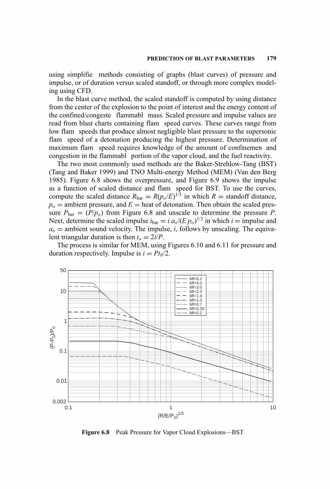
PREDICTION OF BLAST PARAMETERS 179
using simplifie methods consisting of graphs (blast curves) of pressure andimpulse, or of duration versus scaled standoff, or through more complex model-ing using CFD.
In the blast curve method, the scaled standoff is computed by using distancefrom the center of the explosion to the point of interest and the energy content ofthe confined/congeste flammabl mass. Scaled pressure and impulse values areread from blast charts containing flam speed curves. These curves range fromlow flam speeds that produce almost negligible blast pressure to the supersonicflam speed of a detonation producing the highest pressure. Determination ofmaximum flam speed requires knowledge of the amount of confinemen andcongestion in the flammabl portion of the vapor cloud, and the fuel reactivity.
The two most commonly used methods are the Baker-Strehlow-Tang (BST)(Tang and Baker 1999) and TNO Multi-energy Method (MEM) (Van den Berg1985). Figure 6.8 shows the overpressure, and Figure 6.9 shows the impulseas a function of scaled distance and flam speed for BST. To use the curves,compute the scaled distance Rbar = R(po/E)1/3 in which R = standoff distance,po = ambient pressure, and E = heat of detonation. Then obtain the scaled pres-sure Pbar = (P/po) from Figure 6.8 and unscale to determine the pressure P.Next, determine the scaled impulse ibar = i ao/(E po)1/3 in which i= impulse andao = ambient sound velocity. The impulse, i, follows by unscaling. The equiva-lent triangular duration is then to = 2i/P.
The process is similar for MEM, using Figures 6.10 and 6.11 for pressure andduration respectively. Impulse is i = Pt0/2.
50
Mf=5.2Mf=4.0Mf=3.0Mf=2.0Mf=1.4Mf=1.0Mf=0.7Mf=0.35Mf=0.2
10
1
0.1
(P-P
0)/P
0
0.1 1
0.01
0.00210
(R/E/P0)1/3
Figure 6.8 Peak Pressure for Vapor Cloud Explosions—BST
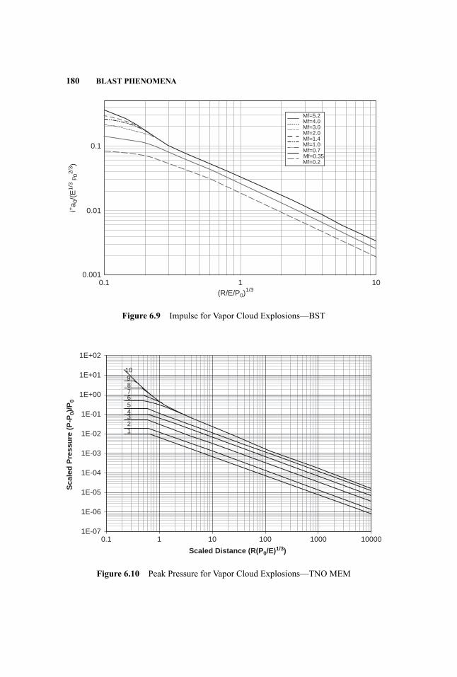
180 BLAST PHENOMENA
Mf=5.2Mf=4.0Mf=3.0Mf=2.0Mf=1.4Mf=1.0Mf=0.7Mf=0.35Mf=0.2
0.1
0.1 1
0.01
0.00110
(R/E/P0)1/3
i+a 0
/(E
1/3
p 02/
3 )
Figure 6.9 Impulse for Vapor Cloud Explosions—BST
1E+02
10987654321
1E+01
1E+00
1E-01
1E-02
1E-03
Sca
led
Pre
ssu
re (
P-P
0)/P
0
1E-04
1E-05
1E-06
1E-070.1 1 10 100 1000 10000
Scaled Distance (R(P0/E)1/3)
Figure 6.10 Peak Pressure for Vapor Cloud Explosions—TNO MEM
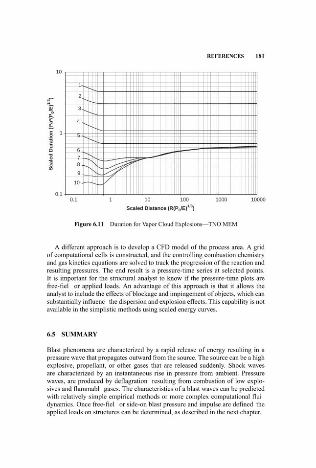
REFERENCES 181
10
1
9
876
5
4
3
2
1
0.10.1 1 10 100 1000 10000
10
Scaled Distance (R(P0/E)1/3)
Sca
led
Du
rati
on
(t*
a*(P
0/E
)1/3 )
Figure 6.11 Duration for Vapor Cloud Explosions—TNO MEM
A different approach is to develop a CFD model of the process area. A gridof computational cells is constructed, and the controlling combustion chemistryand gas kinetics equations are solved to track the progression of the reaction andresulting pressures. The end result is a pressure-time series at selected points.It is important for the structural analyst to know if the pressure-time plots arefree-fiel or applied loads. An advantage of this approach is that it allows theanalyst to include the effects of blockage and impingement of objects, which cansubstantially influenc the dispersion and explosion effects. This capability is notavailable in the simplistic methods using scaled energy curves.
6.5 SUMMARY
Blast phenomena are characterized by a rapid release of energy resulting in apressure wave that propagates outward from the source. The source can be a highexplosive, propellant, or other gases that are released suddenly. Shock wavesare characterized by an instantaneous rise in pressure from ambient. Pressurewaves, are produced by deflagration resulting from combustion of low explo-sives and flammabl gases. The characteristics of a blast waves can be predictedwith relatively simple empirical methods or more complex computational fluidynamics. Once free-fiel or side-on blast pressure and impulse are defined theapplied loads on structures can be determined, as described in the next chapter.

182 BLAST PHENOMENA
REFERENCES
Baker W. E. 1973. Explosions in Air. Austin: University of Texas Press.Baker, Q.A. and W. E. Baker. 1991. Pros and cons of TNT equivalence for industrialexplosion accidents. Presented at AIChE International Conference on Workshop onModeling and Mitigating the Consequences of Accidental Releases of Hazardous Ma-terials, New Orleans, LA, May 21–24, 1991.
Center for Chemical Process Safety. 1994. Guidelines for Evaluating the Characteristicsof Vapor Cloud Explosions, Flash Fires, and BLEVES. New York: American Instituteof Chemical Engineers.
Cooper, W. P. and R. S. Kurowski. 1996. Introduction to the Technology of Explosives.New York: Wiley-VCH.
Tang M. J. and Q. A. Baker. 1999. A new set of blast curves from vapor cloud explosion.Process Safety Progress 18 (4): 235–240.
Tang, M. J., C. Y. Cao, and Q. A. Baker. 1996. Calculation of blast effects from burst-ing vessels.” Presented at the 30th Annual AIChE Loss Prevention Symposium, NewOrleans, LA, February 1996.
U.S. Department of Defense. 2008. Structures to Resist the Effects of Accidental Explo-sions (UFC 3-340-02). Washington, DC: U.S. Department of Defense.
Van Den Berg, A. C. 1985. The multi-energy method—A framework for vapor cloudblast prediction.” Journal of Hazardous Materials, 12 (1): 1–10.

7 Blast Loading
Paul F. Mlakar and William Bounds
7.1 INTRODUCTION
In the previous chapter, blast phenomena and the characteristics of blast waveswere discussed. In this chapter, methods for determining the dynamic blast load-ing on structural elements from these characteristics are discussed. Emphasis isplaced on simple approximate procedures that apply widely in practical blast-resistant design. More comprehensive methods are also discussed.
7.2 EMPIRICAL METHOD
Although research into the effects of explosions dates back to 1870, most de-velopment to determine the blast loading on buildings and other similar struc-tures was started in the 1950s and 1960s by the U.S. military. Several publiclyavailable military manuals were distributed during this period (TM 5-856 andTM 5-1300) that presented empirically-derived charts and equations. Several pa-pers and publications published during that period (Newmark 1956, Biggs 1964,ASCE 1985) also provided information for design.
The empirical method consists of published equations, graphs, tables, andfigure that allow one to determine the principal loading of a blast wave on abuilding or a similar structure. Software has also been developed to automatecalculations based on this same source information. The basic advantage of em-pirical methods is speed and simplicity. Applicable factors and coefficient canbe looked up in tables, blast loading can be calculated manually, and a buildingblast load can be determined in a matter of minutes. Empirical methods are alsowell suited for situations where the accuracy of the blast source location andmagnitude is uncertain. More comprehensive methods, such as computationalflui dynamics (CFD), require specialized software, operator training, and, po-tentially, weeks of data input and verification The disadvantage of empiricalmethods is the lack of fl xibility in application. Most data are based on plainrectangular target structures located in open terrain. Explosions are assumed tobe either an air blast or surface blast. The blast wave is typically based on high
183
Handbook for Blast-Resistant Design of Buildings Edited by Donald 0. Dusenberry
Copyright 0 2010 by John Wiley & Sons, Inc. All rights reserved.
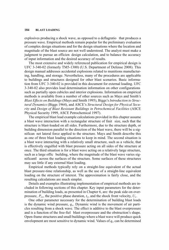
184 BLAST LOADING
explosives producing a shock wave, as opposed to a deflagratio that produces apressure wave. Empirical methods remain popular for the preliminary evaluationof complex design situations and for the design situations where the location andmagnitude of the blast source are not well understood. The analyst must make ajudgment to pursue an efficien design calculation, and to balance the accuracyof input information and the desired accuracy of results.
The most extensive and widely referenced publication for empirical design isUFC 3-340-02 (formerly TM5-1300) (U.S. Department of Defense 2008). Thisdesign manual addresses accidental explosions related to munitions manufactur-ing, handling, and storage. Nevertheless, many of the procedures are applicableto buildings and structures designed for other blast scenarios. Basic informa-tion from UFC 3-340-02 is provided in this document for external loading. UFC3-340-02 also provides load determination information on other configurationssuch as partially open cubicles and interior explosions. Information on empiricalmethods is available from a number of other sources such as Mays and Smith’sBlast Effects on Buildings (Mays and Smith 1995), Biggs’s Introduction to Struc-tural Dynamics (Biggs 1964), and ASCE’s Structural Design for Physical Secu-rity and Design of Blast Resistant Buildings in Petrochemical Facilities (ASCEPhysical Security 1999, ASCE Petrochemical 1997).
The empirical blast load example calculations provided in this chapter assumea blast wave interaction with a rectangular structure of finit size, such that thestructure is blast-loaded on all sides. Furthermore, due to the structure depth, orbuilding dimension parallel to the direction of the blast wave, there will be a sig-nifican net lateral force applied to the structure. Mays and Smith describe thisas one of three blast loading situations to keep in mind. The second situation isa blast wave interacting with a relatively small structure, such as a vehicle, thatis effectively engulfed with blast pressure acting on all sides of the structure atonce. The third situation is for a blast wave acting on a relatively large structure,such as a large offic building, where the magnitude of the blast wave varies sig-nificantl across the surfaces of the structure. Some surfaces of these structuresmay see little if any external blast loading.
Empirical methods typically rely on a straight-line equivalent of the actualblast pressure-time relationship, as well as the use of a straight-line equivalentloading on the structure of interest. The approximation is fairly close, and theresulting calculations are much simpler.
Details and examples illustrating implementation of empirical methods are in-cluded in following sections of this chapter. Key input parameters for the deter-mination of building loads, as presented in Chapter 6, are: the peak side-on over-pressure, Pso, the positive phase duration, to, and the shock front velocity, Us .
One other parameter necessary for the determination of building blast loadsis the dynamic wind pressure, qo. Dynamic wind is the movement of air parti-cles resulting from a shock wave. The effect is additive to the blast overpressureand is a function of the free-fiel blast overpressure and the obstruction’s shape.Open-frame structures and small buildings where a blast wave will produce quickenvelopment are most sensitive to dynamic wind. Values of qo can be determined
EMPIRICAL METHOD 185
Figure 7.1 Peak Incident Pressure versus Peak Dynamic Pressure, Density of AirBehind the Shock Front, and Particle Velocity (UFC 3-340-02)
from Figure 7.1. Alternatively, in the low overpressure range, and at sea levelatmospheric pressure, the following equation from Newmark can be used.
qo = 0.022 (Pso)2 (7.1)
The pressure exerted on a structural element is the dynamic wind pressuremultiplied by a drag coefficient The drag coefficient Cd , is a function of theshape and orientation of the obstructing element. Newmark lists approximatevalues of Cd for open-frame structural elements as 2 for structural shapes, 1.25for box shapes, and 0.8 for cylinders. Values ofCd for enclosed rectangular build-ings are provided in the following sections.

186 BLAST LOADING
7.2.1 Empirical Method—Basic Blast Wave Example
The example calculation presented in the following sections is based on the blastwave and building parameters described below. The given blast wave will be ap-plied normal to the long side of a rectangular flat-roo building. It is further de-termined that the distance to the explosion and the length of the building are suchthat the overpressure and duration do not change significantl over the length ofthe building.
Given charge weight, W = 5 tons (TNT) = 10,000 lb:The charge weight, W , should include any applicable safety factorGiven distance from source to building, R = 215 ftThe blast wave parameters, computed using Figure 6.6 as follows:To use Figure 6.6, compute the scaled distance:
Z = R/W 1/3 = (215 ft)/(10,000 lb)1/3 = 10.0
Using Z = 10, use Figure 6.6 to determine the following parameters:Peak side-on overpressure, Pso = 10 psiShock front velocity, Us = 1.4 ft/msScaled positive phase duration, to/W 1/3 = 2.6 ms/lb1/3Compute the positive phase duration:
to = (to/W 1/3)W 1/3 = (2.6 ms/lb1/3)(10,000 psi)1/3 = 56 ms
Compute the positive phase wave length:
Lw = (Us)to = (1.4 ft/ms)(56 ms) = 78 ft
With Pso = 10 psi, use Figure 7.1 to determine the peak dynamic wind pres-sure, qo = 2.1 psi
Alternatively, use Equation 7.1 to calculate the peak dynamic wind pressure,
qo = 0.022 (Pso)2 = 0.022 (10 psi)2 = 2.2 psi
Loads are to be computed on an aboveground rectangular building with thefollowing dimensions,
Building height, BH = 20 ftBuilding width, BW = 150 ftBuilding depth, BD = 50 ft
7.3 FRONTWALL LOADS
The wall facing the explosion source is subjected to a reflectio effect as theblast wave impacts the facing wall and reflect back towards the blast source.The reflectio effect amplifie the blast pressure on the front or facing side of thebuilding. Because the overpressure at the top and side edges of the front wall is
FRONTWALL LOADS 187
reflectedshockfront
rarefactionwave
reflectedshockfront
shock front
vortex
shock frontvortex
rarefactionwave
Figure 7.2 Blast Wave at Front Wall (TNO Green Book)
less than the reflecte overpressure (Figure 7.2), a decay in the reflectio effecttakes place that starts at the edges and works inward. The effect is completelyremoved after what is called the clearing time, tc. The clearing time is a functionof the height and width of the front wall.
The peak reflecte overpressure, Pr , can be determined from Figure 7.3 usingthe free-fiel peak overpressure. Alternatively, for free-fiel peak overpressures
Figure 7.3 Peak Incident Pressure versus the Ratio of Normal Reflecte Pressure/Incident Pressure for a Free-Air Burst (UFC 3-340-02)
188 BLAST LOADING
less than 40 psi and for sea level atmospheric pressures, the peak reflecte over-pressure can be determined using the following equation form Newmark:
Pr = [2+ 0.05 (Pso)]Pso (7.2)
The clearing time can be calculated using the following equation from UFC 3-340-02.
tc = 4S/[1+ S/G]Cr (7.3)
In the preceding equation, S is the lesser of building height or building width.G is the greater of building height or width, and Cr is the velocity of sound andcan be determined using Figure 7.4.
For the calculation of front wall dynamic wind pressure, a drag coefficientCd , equal to 1.0 is used with the qo value determined from Figure 7.1.
To compute the remainder of the pressure-time curve, the following equationsare used for stagnation pressure, Ps , impulse, Is , and the effective duration, te,based on a simplifie straight-line approximation. These values are illustrated inFigure 7.5.
Ps = Pso + Cd (qo) (7.4)Is = 0.5 (Pr − Ps)tc + 0.5Psto (7.5)te = 2Is/Pr (7.6)
The blast wave angle of incidence affects the blast pressure load on the frontwall. This angle is taken as 0◦ for a blast wave traveling perpendicular into theplane of the front wall where the full reflecte overpressure is applied, and takenas 90◦ for a blast wave traveling parallel to a surface, where the free-field or side-on overpressure is applied. For intermediate values of the angle of incidence,Figure 7.6 provides coefficient to calculate the applied pressure for use in thefollowing equation.
Prα = (Crα)(Pso) (7.7)
7.3.1 Empirical Method—Front Wall Loading Example
The front wall is assumed to span vertically from foundation to roof. The calcu-lation will be for a typical wall segment one foot wide.
With Pso = 10 psi, use Figure 7.3 to determine the reflecte overpressureratio, Pr/Pso = 2.5.
Pr = (Pr/Pso)Pso = (2.5)(10 psi) = 25 psi

Figure7.4
VelocityofSoundinReflecte
OverpressureRegionversus
Peak
IncidentOverpressure(UFC
3-340-02)
189

190 BLAST LOADING
P
t
Pr
Ps
tc te td
Equivalent Loading
Figure 7.5 Front Wall Loading Diagram
Alternatively, use Equation 7.2 to compute the reflecte overpressure,
Pr = [2+ 0.05 (Pso)]Pso = [2+ 0.05(10 psi)](10 psi) = 25 psi
To compute the reflecte pressure clearing time, two parameters are needed,
S = minimum of BH or BW = minimum of 20 ft or 150 ft = 20 ftG = larger of BH or BW = larger of 20 ft or 150 ft = 150 ft
With Pso = 10 psi, use Figure 7.4 to determine the sound velocity in the re-flecte region, Cr = 1.28 ft/ms
Use Equation 7.3 to compute the reflecte overpressure clearing time,
tc = 4S/[1+ S/G]Cr = 4(20 ft)/[1+ (20 ft)/(150 ft)](1.28 ft/ms) = 55 ms
This result is nearly equal to to, thus tc ≈ to = 56 msDrag coefficient Cd = 1.0Use Equation 7.4 to calculate the stagnation pressure,
Ps = Pso + Cd (qo) = (10 psi)+ (1.0)(2.2 psi) = 12.2 psi
Use Equation 7.5 to calculate the front wall impulse,
Is = 0.5 (Pr − Ps)tc + 0.5Psto = 0.5 [(25 psi)− (12.2 psi)](56 ms)+ 0.5 (12.2 psi)(56 ms) = 700 psi-ms
Use Equation 7.6 to calculate the effective duration,
te = 2Is/Pr = 2 (700 psi-ms)/(25 psi) = 56 ms
25 psi
56 ms
pressure
time

14 12 10 8 6
Cr� = Pr�/Pso
4 2 00
1020
3040
An
gle
of
inci
den
ce, �
(D
egre
es)
5060
7080
90
5000
3000
2000
1000
500
400
300
200
150
100
70 50 30 20 10 5 2 1 0.5
0.2
Pea
k In
cide
nt O
verp
ress
ure,
psi
Figure7.6
Reflecte
PressureCoefficien
versus
AngleofIncidence(UFC
3-340-02)
191
192 BLAST LOADING
7.3.2 Empirical Method—Oblique Angle Example
Given angle of incidence, α = 40 degreesGiven side-on overpressure, Pso = 10 psiUsing Figure 7.6, determine the reflecte pressure coefficient Crα = 2.4Using Equation 7.7, calculate the reflecte overpressure,
Prα = (C1α)(Pso) = (2.4)(10 psi) = 24 psi
7.4 SIDE WALL AND ROOF LOADS
Roofs and side walls represent surfaces that are parallel to the path of the ad-vancing blast wave. There is no reflectio effect for this situation; however, theaverage pressure applicable to a specifi area, for example a structural element,depends on the length of the blast wave and the length of the structural element.Figure 7.7 shows a diagram of a blast wave traveling across a roof. If a section ofthe roof tributary to a supporting beam is oriented perpendicular to the travelingwave, then the roof length would be short and the blast wave would have a fulleffect. If the roof beam were oriented parallel to the traveling wave, then the rooflength would be longer, the average pressure would be reduced, and a rise timewould become evident. Calculations for these two situations are presented in theside wall and roof examples. Values are obtained as follows:
� Equivalent uniform pressure factor, CE, is determined from Figure 7.8.� Scaled uniform pressure rise time, tr, is determined from Figure 7.9.� Scaled uniform pressure duration, to, is determined from Figure 7.10.
A building’s depth could be significan with respect to the distance from theblast source. Thus the peak free-fiel overpressure for a side or rear surface couldbe lower than that calculated for the front wall. The calculation of peak free-fiel
SHOCK FRONTAT TIME t
bf
Lw
L
Figure 7.7 Roof Loading Diagram

SIDE WALL AND ROOF LOADS 193E
qu
ival
ent
Lo
ad F
acto
r
Wave length/Span length, Lwf/L
0.10.2
Negative
Positive
Negative Pressure, CE = PR/Psof
Positive Pressure, CE = PR/Psof
0.3 0.4 0.5 0.60.70.8 1 2 3 4 5 6 7 8 9 10
0.2
0.4
0.5
0.6
0.7
0.8
0.9
1
0.3
Figure 7.8 Peak Equivalent Uniform Roof Pressure (UFC 3-340-02)
overpressure is determined using the criteria in Chapter 6. In many cases thiseffect is negligible and is ignored, for simplicity.
For the calculation of roof and side wall dynamic wind pressure, a drag coef-ficient Cd , determined from Table 7.1 is used with the qo value determined fromFigure 7.1.

194 BLAST LOADING
0.50.2
0.3
0.4
0.5
0.6
0.7
0.8
0.9
1
2
Numbers next to curves indicatepeak incident overpressure. psi
4
8
16
32
2
3
4
5
0.6 0.7 0.8 0.9
Wave length/Span length, Lwf/L
Sca
led
Ris
e T
ime
1 2
Figure 7.9 Scaled Rise Time of Equivalent Uniform Positive Roof Pressures (UFC 3-340-02)
The total effective pressure on a roof or side wall is determined from thefollowing,
Pa = CE Pso + Cd qo (7.8)
7.4.1 Empirical Method—Side Wall Loading Example
The side wall is the same as the front wall, spanning vertically from foundationto roof. This calculation will be for a unit width wall segment, L = 1 ft.

SIDE WALL AND ROOF LOADS 195
Figure 7.10 Scaled Duration of Equivalent Uniform Roof Pressures (UFC 3-340-02)

196 BLAST LOADING
Table 7.1 Roof, Side Wall, and Rear WallDrag Coefficient
Peak dynamic pressure Drag coefficien
0–25 psi −0.4025–50 psi −0.3050–130 psi −0.20
With qo = 2.2 psi, use Table 7.1 to determine the drag coefficient Cd = −0.4To determine the equivalent load values, the following parameter is needed,
Lw/L = (78 ft)/(1 ft) = 78
With such a short wall segment in comparison to the blast wave length, it isn’tnecessary to obtain values from Figures 7.8, 7.9, and 7.10.
By inspection, CE = 1.0, use Equation 7.8 to calculate the effective peakoverpressure,
Pa = CE Pso + Cd qo = (1.0)(10 psi)+ (−0.4)(2.2 psi) = 9.1 psi
By inspection, the effective rise time, tr = 0.0 msBy inspection, the effective duration, td = 56 ms
9.1 psi
56 ms
pressure
time
7.4.2 Empirical Method—Roof Loading Example
The roof is a slab spanning between roof beams, and an appropriate span shouldbe used for L . However, to illustrate the use of the figures a section spanning theentire building will be used, thus L = 50 ft
With qo = 2.2 psi, use Table 7.1 to determine the drag coefficient Cd = −0.4To determine the equivalent load values, the following parameter is needed,
Lw/L = (78 ft)/(50 ft) = 1.6
With Lw/L = 1.6, use Figure 7.8 to determine the effective uniform pressurefactor, CE ≈ 0.60
REARWALL LOADS 197
Use Equation 7.8 to calculate the effective peak overpressure,
Pa = CE Pso + Cd qo = (0.60)(10 psi)+ (−0.4)(2.2 psi) = 5.1 psi
With Lw/L = 1.6, use Figure 7.9 to determine the effective scaled rise time,
tr/W 1/3 ≈ 1.4 ms/lb1/3
Rise time, tr = (tr/W1/3)(W1/3) = (1.4 ms/lb1/3)(10,000 lb)1/3 = 30 msWith Lw/L = 1.6, use Figure 7.10 to determine the effective scaled duration,
td/W 1/3 ≈ 3.0
Duration, td = (td/W1/3(W1/3) = (3.0 ms/lb1/3)(10,000 lb)1/3 = 65 msTotal positive phase duration
to = tr + td = (30 ms)+ (65 ms) = 95 ms
7.5 REARWALL LOADS
The rear wall is the wall facing directly away from the blast source, as illustratedin Figure 7.11. The calculation of rear wall blast loads is similar to that for theside walls or roof. In fact, UFC 3-340-02 treats the rear wall as a roof extension.
For the calculation of rear wall dynamic wind pressure, a drag coefficient Cd ,determined from Table 7.1, is used with the qo value determined from Figure 7.1.
7.5.1 Empirical Method—Rear Wall Loading Example
The example will be for a wall segment 1 foot wide, L = building height = 20 ftWith qo = 2.2 psi, use Table 7.1 to determine the drag coefficient Cd = −0.4To determine the equivalent load values, the following parameter is
needed,
Lw/L = (78 ft)/(20 ft) = 3.9
diffracted
shock
front
shock front
vortex
shock front
vortex
diffracted
shock
front
Figure 7.11 Rear Wall (TNO Green Book)
198 BLAST LOADING
With Lw/L = 3.9, use Figure 7.8 to determine the effective uniform pressurefactor, CE ≈ 0.85
Use Equation 7.8 to calculate the effective peak overpressure,
Pa = CE Pso + Cd qo = (0.85)(10 psi)+ (−0.4)(2.2 psi) = 7.6 psi
With Lw/L = 3.9, extrapolate from Figure 7.9 to approximate the effectivescaled rise time, tr/W 1/3 ≈ 0.5 ms/lb1/3
rise time, tr = (tr/W 1/3)(W 1/3) = (0.5 ms/lb1/3)(10,000 lb)1/3 = 11 ms
Note that an alternative rise time calculation, based on the time for the shockfront to travel across the element, would be tr = L/Us = (20 ft)/(1.4 ft/ms) =14 ms
With Lw/L = 3.9, extrapolate from Figure 7.10 to approximate the effectivescaled duration, td/W 1/3 ≈ 2.1
Duration, td = (td/W1/3(W1/3) = (2.1 ms/lb1/3)(10,000 lb)1/3 = 45 msNote that the duration approaches the free fiel duration as Lw/L gets large.Total positive phase duration,
to = tr + td = (11 ms)+ (45 ms) = 56 ms
7.6 psi
56 ms
pressure
time 11 ms
7.6 CONFINED EXPLOSIONS
As discussed in Chapter 6 an interior explosion involves more phenomena thanan external explosion, and the loading (Figure 7.12) changes accordingly. In theinternal explosion, there is firs the directly incident shock as in an external ex-plosion. This is followed by multiple shock reflection off the other surfacesthat are confinin the explosion. Finally, there is a longer duration gas pressurethroughout the interior as the gaseous products of the detonation come to ther-modynamic equilibrium.
In practice, it is often convenient to approximate this typical loading with asuddenly applied bilinear pulse, as shown in Figure 7.13. The firs part of thisloading is the directly incident shock as computed in Section 7.3 for front wallloads. The second part is a triangular approximation to the gas pressure, whichgenerally has a lower peak but longer duration than the shock loading.
CONFINED EXPLOSIONS 199
Figure 7.12 Loading from Confine Explosion
To calculate this gas pressure loading, the peak gas pressure, Pg, is ob-tained from Figure 6.7, as described in the previous chapter. Then the scaledgas impulse, ig/W 1/3, is computed from Figures 7.14 through 7.25 as a func-tion of loading density, W/V f , the scaled reflecte shock impulse, ir/W 1/3, andthe scaled mass, WF/W 1/3, of the frangible openings in the confine volume.Table 7.2 indicates which of the Figures 7.14 through 7.25 pertains to various
IDEALIZED SHOCKPRESSURES
ir = REFLECTED IMPULSE
IDEALIZED GASPRESSURESP
RE
SS
UR
E
TIME
Figure 7.13 Approximate Loading from Confine Explosion
200 BLAST LOADING
Table 7.2 Figures for Scaled Gas Impulse ig/W1/3
ir/W1/3 = 20 ir/W1/3 = 100 ir/W1/3 = 600 ir/W1/3 = 2,000
W/Vf = 0.002 Fig. 7.14 Fig. 7.15 Fig. 7.16W/Vf = 0.015 Fig. 7.17 Fig. 7.18 Fig. 7.19W/Vf = 0.15 Fig. 7.20 Fig. 7.21 Fig. 7.22W/Vf = 1.0 Fig. 7.23 Fig. 7.24 Fig. 7.25
10000
1000
100
SC
AL
ED
GA
S IM
PU
LS
E, i
g/W
1/3
(psi
- m
sec/
lb1/
3 )
10
10.01 0.1
0.3
SCALED VENT AREA, A/Vf2/3
1
1
3
10
30
100
wr/w1/3
0
10
Figure 7.14 Scaled Gas Impulse for W/V f = 0.002 and ir/W 1/3 = 20
CONFINED EXPLOSIONS 201
10000
1000
100
SC
AL
ED
GA
S IM
PU
LS
E, i
g/W
1/3
(psi
- m
sec/
lb1/
3 )
10
10.01 0.1
0.3
SCALED VENT AREA, A/Vf2/3
1
1
3
10
30
100
wr/w1/3
0
10
Figure 7.15 Scaled Gas Impulse for W/V f = 0.002 and ir/W 1/3 = 100
values of W/V f and ir/W 1/3. For values between those given in this table, thescaled gas impulse may be found by interpolation. Once the scaled gas impulseis obtained, the actual impulse follows by unscaling, i.e., multiplication byW 1/3.The equivalent triangular duration of the gas loading is then tg = 2ir/Pg .
For example, let us estimate the loading from the detonation of W = 16 lbsof TNT at the center of the floo a cubicle that measures 20 ft on a side. Suppose
202 BLAST LOADING
10000
1000
100
SC
AL
ED
GA
S IM
PU
LS
E, i
g/W
1/3
(psi
- m
sec/
lb1/
3 )
10
10.01 0.1
0.3
SCALED VENT AREA, A/Vf2/3
1
1
3
10
30
100
wr/w1/3
0
10
Figure 7.16 Scaled Gas Impulse for W/V f = 0.002 and ir/W 1/3 = 600
that the total vent area is A = 20 ft2 and the weight of the frangible surfaces isWF = 25 lbs.Using the method described in Section 7.3, the directly incident shock is de-
scribed by
Pr = 317 psito = 0.868 msec
CONFINED EXPLOSIONS 203
10000
1000
100
SC
AL
ED
GA
S IM
PU
LS
E, i
g/W
1/3
(psi
- m
sec/
lb1/
3 )
10
10.01 0.1
0.3
SCALED VENT AREA, A/Vf2/3
1
1
3
10
30
100
wr/w1/3
0
10
Figure 7.17 Scaled Gas Impulse for W/V f = 0.015 and ir/W 1/3 = 20
For the gas pressure, the loading density is
W/V f = 16/203 = 0.002 lbs/ft3
From Figure 6.7, the corresponding peak pressure is
Pg = 25.5 psi
204 BLAST LOADING
10000
1000
100
SC
AL
ED
GA
S IM
PU
LS
E, i
g/W
1/3
(psi
- m
sec/
lb1/
3 )
10
10.01 0.1
0.3
SCALED VENT AREA, A/Vf2/3
1
1
3
10
30
100
wr/w1/3
0
10
Figure 7.18 Scaled Gas Impulse for W/V f = 0.015 and ir/W 1/3 = 100
For the scaled reflecte shock impulse, ir/W1/3 = 54.6 psi × msec/lb1/3Interpolation between Figures 7.14 and 7.15 gives the scaled gas impulse
ig/W1/3 = 1990 psi × msec/lb1/3The actual gas impulse is then
ig = 1990× 161/3 = 5010 psi×msec
CONFINED EXPLOSIONS 205
10000
1000
100
SC
AL
ED
GA
S IM
PU
LS
E, i
g/W
1/3
(psi
- m
sec/
lb1/
3 )
10
10.01 0.1
0.3
SCALED VENT AREA, A/Vf2/3
1
1
3
10
30
100
wr/w1/3
0
10
Figure 7.19 Scaled Gas Impulse for W/V f = 0.015 and ir/W 1/3 = 600
and the equivalent triangular duration is
tg = 2× 5010/25.5 = 393 msec
This dynamic loading is summarized in Figure 7.26. As to � tg in this case,the shock portion appears very close to the vertical axis.

206 BLAST LOADING
10000
1000
100
SC
AL
ED
GA
S IM
PU
LS
E, i
g/W
1/3
(psi
- m
sec/
lb1/
3 )
10
10.01 0.1
0.3
SCALED VENT AREA, A/Vf2/3
1
1
3
10
30
100
wr/w1/3
0
10
Figure 7.20 Scaled Gas Impulse for W/V f = 0.15 and ir/W 1/3 = 20
7.7 LEAKAGE
If the openings in the exterior of a structure are not designed for an expectedblast loading, there will be a leakage of pressure into the interior. Idealizedpressure-time series for this loading are discussed in UFC 3-340-02 as a function

LEAKAGE 207
10000
1000
100
SC
AL
ED
GA
S IM
PU
LS
E, i
g/W
1/3
(psi
- m
sec/
lb1/
3 )
10
10.01 0.1
0.3
SCALED VENT AREA, A/Vf2/3
1
1
3
10
30
100
wr/w1/3
0
10
Figure 7.21 Scaled Gas Impulse for W/V f = 0.15 and ir/W 1/3 = 100
of the structural geometry and shock wave characteristics. Different curves aredeveloped for the exterior front wall, interior front wall, interior side wall androof, and interior back wall. This manual also discusses closures that are delib-erately designed to resist the blast but have small openings for vents and ductsthat admit some overpressure.
208 BLAST LOADING
10000
1000
100
SC
AL
ED
GA
S IM
PU
LS
E, i
g/W
1/3
(psi
- m
sec/
lb1/
3 )
10
10.01 0.1
0.3
SCALED VENT AREA, A/Vf2/3
1
1
3
10
30
100
wr/w1/3
0
10
Figure 7.22 Scaled Gas Impulse for W/V f = 0.15 and ir/W 1/3 = 600
7.8 RAY-TRACING PROCEDURES
Ray-tracing algorithms have been developed to provide a higher resolution ofthe blast loading than provided by the previously discussed empirical meth-ods in complex geometrical situations. These procedures generally work back-wards from each location of interest on a structure to capture a finit number

RAY-TRACING PROCEDURES 209
100000
10000
1000
SC
AL
ED
GA
S IM
PU
LS
E, i
g/W
1/3
(psi
- m
sec/
lb1/
3 )
100
100.01 0.1
0.3
SCALED VENT AREA, A/Vf2/3
1
1
3
10
30
100
wr/w1/3
0
10
Figure 7.23 Scaled Gas Impulse for W/V f = 1.0 and ir/W 1/3 = 100
of the possible multiple reflection at each location. As more reflection areconsidered, the fidelit increases, but so does the computational effort. In prac-tice, the coefficient of such physics-based models are “tuned” to match testdata. Accordingly, these are often termed “semi-empirical” models. Their appli-cability is limited to configuration and charge weight ratios for which data areavailable. Some semi-empirical codes have the capability to approximate shock

210 BLAST LOADING
100000
10000
1000
SC
AL
ED
GA
S IM
PU
LS
E, i
g/W
1/3
(psi
- m
sec/
lb1/
3 )
100
100.01 0.1
0.3
SCALED VENT AREA, A/Vf2/3
1
1
3
10
30
100
wr/w1/3
0
10
Figure 7.24 Scaled Gas Impulse for W/V f = 1.0 and ir/W 1/3 = 600
diffraction, shielding, and reflection In both fidelit and computational effort,these methods lie between the previously discussed fully empirical proceduresand fully physics-based computational flui dynamics. These semi-empiricalmethods have been developed primarily by defense-related agencies and are re-stricted in distribution to the government and its contractors.
RAY-TRACING PROCEDURES 211
100000
10000
1000
SC
AL
ED
GA
S IM
PU
LS
E, i
g/W
1/3
(psi
- m
sec/
lb1/
3 )
100
100.01 0.1
0.3
SCALED VENT AREA, A/Vf2/3
1
1
3
10
30
100
wr/w1/3
0
10
Figure 7.25 Scaled Gas Impulse for W/V f = 1.0 and ir/W 1/3 = 2,000
212 BLAST LOADING
Figure 7.26 Approximate Loading for Detonation of 16 lbs of TNT in a 20-ft Cubicle
7.9 SUMMARY
In this chapter, methods for determining the dynamic blast loading on structuralelements from the characteristics of blast phenomena have been discussed andillustrated with examples. Emphasis was placed on simple approximate proce-dures that apply widely in practical blast-resistant design. More comprehensivemethods were also discussed.
REFERENCES
ASCE. 1985. Design of Structures to Resist Nuclear Weapons Effects (Manual No. 42).Reston, VA: American Society of Civil Engineers.
ASCE Petrochemical. 1997. Design of Blast Resistant Buildings in Petrochemical Fa-cilities. Reston, VA: Task Committee on Blast Resistant Design, American Society ofCivil Engineers.
ASCE Physical Security. 1999. Structural Design for Physical Security, Reston, VA:American Society of Civil Engineers.
Biggs J. M. 1964. Introduction to Structural Dynamics. New York: McGraw-Hill BookCompany.
Committee for the Prevention of Disasters Due to Dangerous Substances. 1992. Methodfor the determination of possible damage to people and objects resulting from releasesof hazardous materials (CPR 16E) TNO Green Book. The Hague, The Netherlands:The Director-General of Labour.

REFERENCES 213
Mays, G. C. and P. D. Smith, eds. 1995. Blast Effects on Buildings. London: ThomasTedford Publications.
Newmark, Nathan M. 1956. An engineering approach to blast-resistant design (Paper2786). ASCE Transactions 121: 45–64. Reston, VA: American Society of Civil Engi-neers.
U.S. Department of Defense. 1965. Design of Structures to Resist the Effects of AtomicWeapons (TM 5-856). Washington, DC: U.S. Department of Defense.
. 1990. Structures to Resist the Effects of Accidental Explosions (TM 5-1300).Washington, DC: U.S. Department of Defense.
. 2008. Structures to Resist the Effects of Accidental Explosions(UFC 3-340-02). Washington, DC: U.S. Department of Defense.

8 Fragmentation
Kim King
8.1 INTRODUCTION
Injury and structural damage during an explosion may result not only from thedirect pressure and impulse of an air blast, but also from the impact of flyinobjects called debris and fragmentation. Military weapons are typically explosivecharges with some type of metal casing. Upon detonation, this case is rupturedand expelled as fragmentation at high velocity. Similarly, terrorist devices may beembedded with objects such as ball bearings or nails that will be ejected at highvelocity. Other fragmentation may occur as objects interact with the blast wavecreated from a detonation and become airborne. Fragments can range in sizefrom small irregularly shaped objects (fractions of an inch) to large objects suchas portions of buildings or vehicles. Two types of fragments may be generatedduring an explosion: primary and secondary fragments.
Fragmentation generated during an explosion can damage structures by pen-etrating walls as well as impacting structural elements with sufficien impulse tocause material failure or global structural failure of a structural element. Thischapter discusses fragmentation resulting from an explosion and establishedmethods of predicting the hazards of airborne fragments.
8.2 DEBRIS
Debris generically refers to the broken remains of a destroyed object. Debrisfrom a destroyed structure near an explosion can be thrown as secondary frag-mentation.
8.3 LOADINGS
Fragmentation can typically be separated into two categories: primary and sec-ondary fragmentation. Primary fragments are typically produced from the con-tainer or casing of an explosive charge. Primary fragments can also be gener-ated in manufacturing processes where equipment or tools are in contact withexplosive material. Examples of primary fragments include the casing of
215
Handbook for Blast-Resistant Design of Buildings Edited by Donald 0. Dusenberry
Copyright 0 2010 by John Wiley & Sons, Inc. All rights reserved.
216 FRAGMENTATION
conventional munitions, metal containers such as kettles and hoppers used inthe manufacture of explosives, the steel casing of pipe bombs, and the metalhousing of rocket engines. For high explosives, the casing will typically shatterinto many small fragments traveling at very high initial velocities up to severalthousand feet per second. Primary fragments are typically small, on the order of1 gram. They typically have “chunky” or irregular geometry with linear dimen-sions all of the same order. However, some casings are scored or formed to failin a specifi manner to generate a specifi fragment pattern.
Secondary fragments are produced when the shock wave encounters objectsor structures located near the source of detonation. Secondary fragments are alsoknown as “secondary debris” or “secondary missiles.” Secondary fragments aregenerally larger than primary fragments and have lower initial velocities. Ex-amples of secondary fragments include broken glass from window systems, de-bris from exterior walls, and dislodged architectural ornamentation. Secondaryfragmentation can also include items located near (but not in contact with) theexplosive source, such as parts of an automobile near a terrorist vehicle bomb.Damage from secondary fragments is not easy to accurately predict because ofthe variation in size, shape, and initial velocity.
8.3.1 Primary Fragmentation
Much work has been done to characterize the type of fragments and correspond-ing fragment velocity of military munitions. Many factors can affect the primaryfragment shape, mass, and velocity, including the explosive type, shape of the ex-plosive charge, arrangement of casing, and so forth. For simplification the mostcommon shape of a cased explosive (a cylinder) with uniform case thickness willbe considered.
Primary Fragment Shape The shape of primary fragments may be predictableif, for example, the casing is scored to produce a particular shape, or a specifimunition, with a known fragment shape, is known. But a standard shape forprimary fragments is typically assumed for design purposes where a specifishape is not known. The typical fragment shape is shown in Figure 8.1.
Primary Fragment Mass For the most common device shape, a uniform cylin-der, and a given confidenc level (CL ≤ 0.999), the design fragment weight canbe estimated with the following procedure:
Wd f = M2A · ln2(1− CL ) (8.1)
where: Wdf = design fragment weight (ounces)MA = fragment distribution factorCL = confidenc level
LOADINGS 217
d
d
d = Diameter of cylindrical portion offragment
r = Radius of hemispherical portionof fragment (d/2)
n = Caliber radius of the tangent ogive of the fragment nose = r/d = 0.5
N = Nose shape factor = 0.72 + 0.25.(n – 0.25)1/2 = 0.845
D = Caliber density = 0.186.lb/in3
Wf = Fragment weight, 0.645.d3/γ = 0.186.d3
rr
r
r r
Figure 8.1 Standard Primary Fragment Shape
MA = B · t5/6c · d1/3i · (1+ tc/di ) (8.2)
where: B= explosive constant (see Table 8.1)tc = average casing thickness (inch)di = average inside diameter of casing (inch)
Table 8.1 Mott Scaling Constants for Mild Steel Casings and VariousExplosives (Mott 1947)
Explosive A (oz1/2 inches−3/2) B (oz1/2 inches−7/6)
Baratol — 0.512Composition A-3 — 0.22Composition B 0.214 0.222Cyclotol (75/25) — 0.197H-6 — 0.276HBX-1 — 0.256HBX-3 — 0.323Pentolite (50/50) 0.238 0.248PTX-1 — 0.222PTX-2 — 0.227RDX 0.205 0.212Tetryl 0.265 0.272TNT 0.302 0.312
218 FRAGMENTATION
Table 8.2 Gurney Energy
Explosive Specifi Weight (lb/inch3)√2 · E ′
Composition B 0.0621 9100Composition C-3 0.0578 8800HMX 0.0682 9750Nitromethane 0.0411 7900PBX-9404 0.0664 9500PETN 0.0635 9600RDX 0.0639 9600TACOT 0.0581 7000Tetryl 0.0585 8200TNT 0.0588 8000Trimonite No. 1 0.0397 3400Tritonal (TNT/AL - 80/20) 0.0621 7600
Primary Fragmentation Velocity The most common technique for calculatingthe initial velocity of primary fragmentation in contact with an explosive charge,the Gurney method, is provided here (Gurney 1947). The initial velocity of pri-mary fragments produced from a cylindrical cased explosive is a function of theexplosive output and the ratio of the explosive charge weight to casing weight.The initial velocity of primary fragments resulting from a cylindrical cased ex-plosive with evenly distributed explosives and casing is expressed as:
Vop = FS ·√2 · E ′ ·
√√√√ W/Wc
1+ 0.5 ·W/Wc
(8.3)
where: Vop = initial velocity of primary fragment (feet/sec)√2 · E ′ =Gurney Energy Constant (see Table 8.2)FS= factor of safety (1.2)W = design charge weight = FS·Wact (feet/sec)
Wact = actual quantity of explosive material (lb)Wc =weight of casing (lb)
8.3.2 Secondary Fragmentation
Secondary fragments generated during an explosion can represent a wide vari-ety of sizes, shapes, and initial velocities. An array of scenarios must typicallybe considered to establish the design fragment (worst-case loading on the struc-ture). Varying factors such as fragment size, shape, structural constraint, andorientation must be evaluated to establish the controlling fragment scenario thatproduces the most severe response of the structure in question.
LOADINGS 219
ta t1 t2
F (t) = CD.q(t) = CD
.1/2.ρu2
t3 Time
CD.Q
Pr
Pressure
Figure 8.2 Idealized Time Loading on an Irregular Fragment
Initial steps for identifying the hazard associated with secondary fragmenta-tion are listed below.
1. Defin blast loading (see Chapter 7 for blast loading).2. Determine distance from the center of the explosive to the potential frag-
ment (refer to structural details of the equipment and/or structure in con-sideration).
3. Determine the size, shape, and connection of the potential fragment (seestructural details for the equipment and/or structure in consideration).
4. Determine potential fragment velocity using the methods detailed in thischapter.
The blast load applied to the object can be simplifie to a three-step functionthat represents the rise to peak pressure, initial pressure decay that is affected bydiffraction of the wave around the object and rarefaction waves that form acrossthe front of the object, and finall the drag phase loading (see Figure 8.2).
Unconstrained Fragments Unconstrained fragments are generated when ob-jects that are not attached interact with the blast wave and are thrown from theincident origin. Predictions for unconstrained fragment velocity assume that theobject is not attached (i.e., no energy lost breaking the object free), the objectwill not deform, and gravity will not affect velocity during acceleration.
220 FRAGMENTATION
Unconstrained Fragments Far from the Charge Potential fragments are defineas far from the charge if the objects are located at a distance more than 20 timesthe radius of the explosive. For potential fragments located far from the charge,the initial fragment velocity can be calculated using the following methods (U.S.Department of Defense 2008).
The basic equation of motion describes the object acceleration, where thetime-dependent pressure applied to the area of the object facing the blast is equalto the mass of the object times acceleration. This relationship can be integratedand rearranged to yield:
V (td ) =td∫
0
AMid (8.4)
where: V = velocity (feet/sec)td = load duration (msec)A= area of object facing blast (inches2)M=mass of object (lb-msec2/inch)id = total drag and diffraction (psi-msec/lb1/3)
Equation 8.4 can be explicitly resolved if the loading history can be mathe-matically define in a function. However, Figure 8.3 can be used to graphicallysolve for the nondimensional velocity and then solve for the object initial veloc-ity, by solving for the quantity Pso/Po (on the ordinate) and the following valueon the abscissa:
12 · CD · is · ao1000 · Pso · (K · H + X )
(8.5)
Establish the nondimensional object velocity using the various curves. Thenondimensional velocity (v) is equal to:
v = 144 · vo · M · ao106 · Po · (K · H + X )
(8.6)
Rearranging Equation 8.6 will result in the initial object velocity.
where: Pso = peak incident overpressure (psi)Po = atmospheric pressure (psi)Cd = drag coefficien (see Figure 8.4)is = incident-specifi impulse (psi-msec)ao = velocity of sound in air (feet/sec)K= constant (see Table 8.3)H=minimum transverse dimension of the mean presented area of
object (inch)
LOADINGS 221
Numbers adjacent to curves indicatenondimensional object velocity =(144 vo
.M.ao)/106.Po.A.(K.H+X)
(12.Cd.js.ao)/(1000.Pso
.(K.H+X))
0.22E-5
0.001
0.01
Pso
Po
0.1
1
5
0.0001
1 10 100 1,000 10,000 100,000
50.0
5.0
1.0
0.10.05
0.0050.001
0.01
0.5
10.0
1,000,000
Figure 8.3 Nondimensional Object Velocity
X= distance from the front of the object to the location of its largestcross section normal to the plane of the shock front (inch)
vo = initial velocity of object (feet/sec)
Unconstrained Fragments Near the Charge Potential fragments are define asnear the charge if the objects are located at a distance less than or equal to 20times the radius of explosive. Initial fragment velocity for potential fragmentscan be calculated using the following methods (U.S. Department of Defense2008).
The firs step to determine the velocity of a close-in unconstrained fragmentis to determine the specifi impulse. Two charge configuration are considered,spherical and cylindrical. For spherical charges with R/Re ≤ 5.07:
iβ · Reff =
[ReRt
]0.158= 38,000 ·
[ReR
]1.4(8.7)
and Reff = ReFor cylindrical charges with R/Re ≤ 5.25:
iβ · Reff =
[ReRt
]0.158= 46,500 ·
[ReR
](8.8)
222 FRAGMENTATION
Circular cylinder (Long rod),side-on
FLOW
FLOW
FLOW
FLOW OR
FLOW
FLOW
FLOW
FLOW
FLOW1.98
1.55
2.05
0.80
1.05
1.17
0.82
0.47
1.20
CO
Rod, end-on
Sphere
Disc, face-on
Cube, face-on
Cube, edge-on
Long rectangular member,face-on
Long rectangular member,edge-on
Narrow strip, face-on
SketchShape
Figure 8.4 Drag Coefficient (Baker et al. 1977)
LOADINGS 223
Table 8.3 K Constant
Steel K-Value
Object on reflectin surface (i.e., on ground) 4Object in air 2
For cylindrical charges with 5.25 < R/Re ≤ 10:
iβ · Reff =
[ReRt
]0.158= 161,700 ·
[ReR
]1.75(8.9)
and
Reff = 0.909 ·[LeRe
]0.333· Re (8.10)
where: i= specifi acquired impulse (psi-msec)β = nondimensional shape factor of the target from Figure 8.5
Reff = effective radius (feet)Re = radius of the explosive (feet)R= standoff distance (feet)Rt = target radius (feet)Le = length of cylindrical explosive (inch)
Figure 8.6 graphically shows specifi acquired impulse for spheres and cylin-ders. The data for this relationship were experimentally derived and should notbe used beyond the distances shown in the figure When these standoff distancesare greater than plotted values, the normal reflecte impulse may be used as anapproximation for specifi acquired impulse.
Because the target is so close to the charge, the actual load history is unim-portant, and the impulse acting on the target is equal to the applied momentum.Therefore, i=M·V/A and the velocity of a specifi target is:
vo = 1000 · i · β · A12 · M (8.11)
Constrained Fragments A constrained secondary fragment is generated whenan object is torn loose from its moorings and thrown from the explosion source.The velocity of a constrained secondary fragment is dependent on the specifiimpulse applied to the object minus the impulse required to free the object fromthe support. Therefore, the following is true:
I − Ist = M · vo (8.12)

224 FRAGMENTATION
Cylindrical Explosive
Spherical Explosive
a) Exposed Flat Face β = 1.0
b) Exposed Cylindrical Surface β = π/4
c) Exposed Spherical Surface β = 2/3
2Rt
2Rt
2Re
2Re
R
Le
Figure 8.5 Nondimensional Shape Factor (U.S. Department of Defense 2008)
50,000
10,000
Spe
cific
Impu
lse
5,000
2,0001 5
R/Re
10
Cylindrical Charge
Spherical Charge
Figure 8.6 Specifi Acquired Impulse
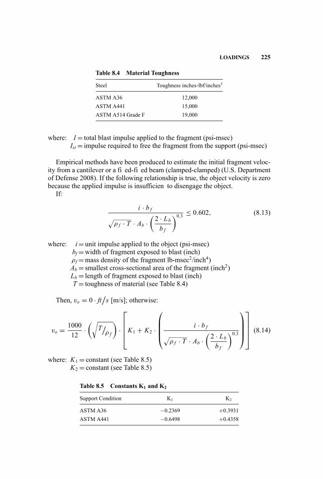
LOADINGS 225
Table 8.4 Material Toughness
Steel Toughness inches-lbf/inches3
ASTM A36 12,000ASTM A441 15,000ASTM A514 Grade F 19,000
where: I= total blast impulse applied to the fragment (psi-msec)Ist = impulse required to free the fragment from the support (psi-msec)
Empirical methods have been produced to estimate the initial fragment veloc-ity from a cantilever or a fi ed-fi ed beam (clamped-clamped) (U.S. Departmentof Defense 2008). If the following relationship is true, the object velocity is zerobecause the applied impulse is insufficien to disengage the object.
If:
i · b f√
ρ f · T · Ab ·(2 · Lbb f
)0.3 ≤ 0.602, (8.13)
where: i= unit impulse applied to the object (psi-msec)bf =width of fragment exposed to blast (inch)ρ f =mass density of the fragment lb-msec2/inch4)Ab = smallest cross-sectional area of the fragment (inch2)Lb = length of fragment exposed to blast (inch)T = toughness of material (see Table 8.4)
Then, vo = 0 · ft/s [m/s]; otherwise:
vo = 100012
·(√
T/ρ f
)·
⎡⎢⎢⎢⎣K1 + K2 ·
⎛⎜⎜⎜⎝
i · b f√
ρ f · T · Ab ·(2 · Lbb f
)0.3
⎞⎟⎟⎟⎠
⎤⎥⎥⎥⎦ (8.14)
where: K1 = constant (see Table 8.5)K2 = constant (see Table 8.5)
Table 8.5 Constants K1 and K2
Support Condition K1 K2
ASTM A36 −0.2369 +0.3931ASTM A441 −0.6498 +0.4358

226 FRAGMENTATION
4
3
2
1
00 1.5 4.53
Ab
i.bf . 2.Lb
60.3
7.5 9 10.5
CantileverClamped-Clamped
ρf.Tv2 =
12.V1000
.√
ρt.T√
bf
Figure 8.7 Scaled Fragment Velocities for Constrained Objects
Figure 8.7 shows Equation 8.14 graphically for both cantilever and fi ed-fi edsupport conditions.
8.4 DESIGN FRAGMENT PARAMETERS
As a fragment is thrown from its initial position, several factors influenc theimpact the fragment will have on the target. Those factors include the fragmenttrajectory, the velocity upon impact, and the angle at which the fragment actuallyimpacts the target (referred to as angle of obliquity). A zero angle of obliquity isthe most conservative and typically assumed for design, since the actual angle ofobliquity is rarely known.
8.4.1 Fragment Final Velocity
Fragment velocities vary with distance due primarily to drag forces. As the frag-ment travels away from the event, the initial velocity will decay until impact.It is assumed the initial velocity is achieved instantaneously. If a target is lo-cated close to an explosive event (less than 20 feet [U.S. Department of Defense2008]), the decay in velocity is minimal and can be ignored. For targets fartherfrom the event, the following method can estimate the fina fragment velocity.
Vs = vo · e−[12·kv ·R f ] (8.15)
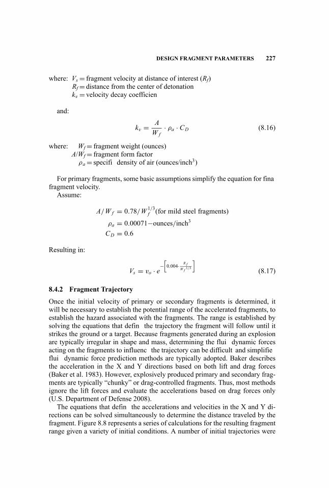
DESIGN FRAGMENT PARAMETERS 227
where: Vs = fragment velocity at distance of interest (Rf)Rf = distance from the center of detonationkv = velocity decay coefficien
and:
kv = AW f
· ρa · CD (8.16)
where: Wf = fragment weight (ounces)A/Wf = fragment form factor
ρa = specifi density of air (ounces/inch3)
For primary fragments, some basic assumptions simplify the equation for finafragment velocity.
Assume:
A/W f = 0.78/W 1/3f (for mild steel fragments)
ρa = 0.00071−ounces/inch3CD = 0.6
Resulting in:
Vs = vo · e−[0.004· R f
W f 1/3
](8.17)
8.4.2 Fragment Trajectory
Once the initial velocity of primary or secondary fragments is determined, itwill be necessary to establish the potential range of the accelerated fragments, toestablish the hazard associated with the fragments. The range is established bysolving the equations that defin the trajectory the fragment will follow until itstrikes the ground or a target. Because fragments generated during an explosionare typically irregular in shape and mass, determining the flui dynamic forcesacting on the fragments to influenc the trajectory can be difficult and simplifieflui dynamic force prediction methods are typically adopted. Baker describesthe acceleration in the X and Y directions based on both lift and drag forces(Baker et al. 1983). However, explosively produced primary and secondary frag-ments are typically “chunky” or drag-controlled fragments. Thus, most methodsignore the lift forces and evaluate the accelerations based on drag forces only(U.S. Department of Defense 2008).
The equations that defin the accelerations and velocities in the X and Y di-rections can be solved simultaneously to determine the distance traveled by thefragment. Figure 8.8 represents a series of calculations for the resulting fragmentrange given a variety of initial conditions. A number of initial trajectories were

228 FRAGMENTATION
0.01 0.1 1
(12.ρ0.CD
.ADv02)/(M.g)
(12.
ρ 0. CD. A
DR
)/M
10 100 1,0000.01
0.05
0.1
0.5
1
5
10
Figure 8.8 Fragment Range Prediction
considered to determine the maximum range; thus, the initial trajectory does nothave to be established to use Figure 8.8. Calculate the nondimensional velocity[v], shown on the abscissa in Figure 8.8, with the following:
v = 12 · ρo · Cd · AD · v2oM · g (8.18)
where: ρo =mass density of the medium through which the object travels (lb-msec2/inch4)AD = drag area (inch2)g= gravity force (32.2 feet/sec2)
From Figure 8.8 determine the dimensional range [R], shown on the ordinate.Rearrange R to solve for the maximum range [R].
R = M · R12 · ρo · Cd · AD (8.19)
8.5 FRAGMENT IMPACT DAMAGE
Almost any type of structure is susceptible to damage from explosively drivenfragmentation. Damage can range from cosmetic damage such as bent or crackedarchitectural features to perforation (where a fragment passes through a wallor structural element), penetration (where a fragment strikes and lodges in a
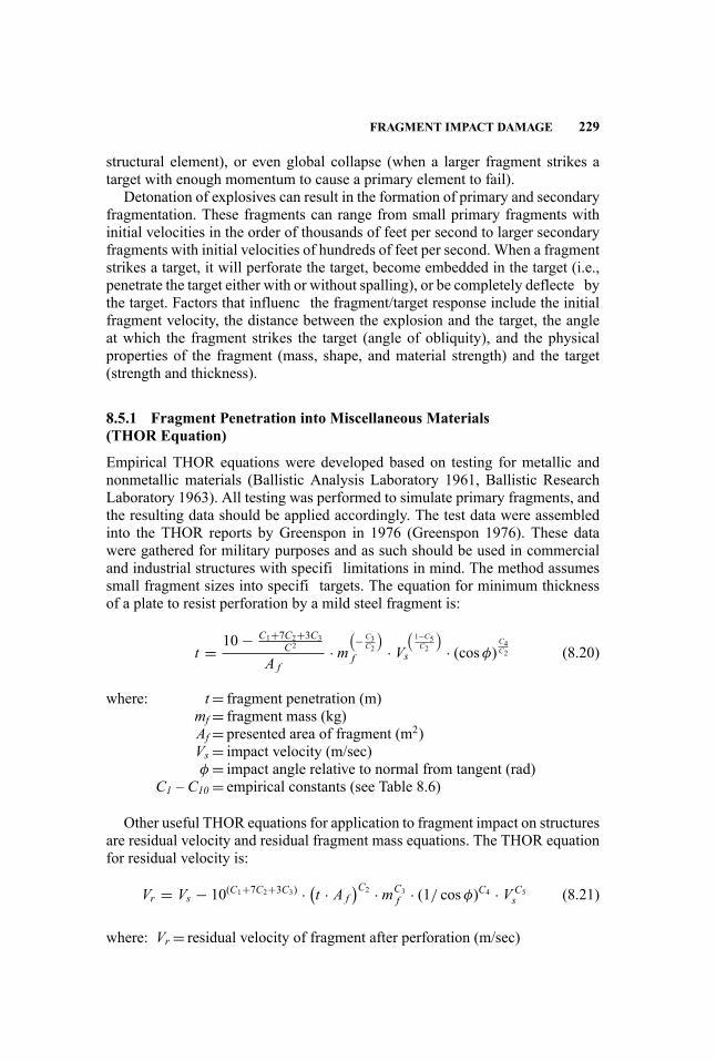
FRAGMENT IMPACT DAMAGE 229
structural element), or even global collapse (when a larger fragment strikes atarget with enough momentum to cause a primary element to fail).
Detonation of explosives can result in the formation of primary and secondaryfragmentation. These fragments can range from small primary fragments withinitial velocities in the order of thousands of feet per second to larger secondaryfragments with initial velocities of hundreds of feet per second. When a fragmentstrikes a target, it will perforate the target, become embedded in the target (i.e.,penetrate the target either with or without spalling), or be completely deflecte bythe target. Factors that influenc the fragment/target response include the initialfragment velocity, the distance between the explosion and the target, the angleat which the fragment strikes the target (angle of obliquity), and the physicalproperties of the fragment (mass, shape, and material strength) and the target(strength and thickness).
8.5.1 Fragment Penetration into Miscellaneous Materials(THOR Equation)
Empirical THOR equations were developed based on testing for metallic andnonmetallic materials (Ballistic Analysis Laboratory 1961, Ballistic ResearchLaboratory 1963). All testing was performed to simulate primary fragments, andthe resulting data should be applied accordingly. The test data were assembledinto the THOR reports by Greenspon in 1976 (Greenspon 1976). These datawere gathered for military purposes and as such should be used in commercialand industrial structures with specifi limitations in mind. The method assumessmall fragment sizes into specifi targets. The equation for minimum thicknessof a plate to resist perforation by a mild steel fragment is:
t = 10− C1+7C2+3C3C2
A f· m
(− C3C2
)f · V
(1−C5C2
)s · (cosφ)
C4C2 (8.20)
where: t= fragment penetration (m)mf = fragment mass (kg)Af = presented area of fragment (m2)Vs = impact velocity (m/sec)φ = impact angle relative to normal from tangent (rad)
C1 – C10 = empirical constants (see Table 8.6)
Other useful THOR equations for application to fragment impact on structuresare residual velocity and residual fragment mass equations. The THOR equationfor residual velocity is:
Vr = Vs − 10(C1+7C2+3C3) · (t · A f
)C2 · mC3f · (1/ cosφ)C4 · VC5
s (8.21)
where: Vr = residual velocity of fragment after perforation (m/sec)
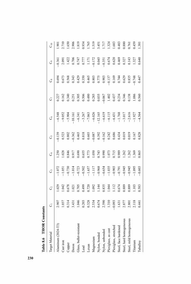
Table8.6
THORConstants
TargetMaterial
C1
C2
C3
C4
C5
C6
C7
C8
C9
C10
Aluminum
(2024-T3)
2.907
1.029
−1.072
1.250
−0.139
−6.548
0.227
0.694
−0.361
1.901
Castiron
1.037
1.042
−1.051
1.028
0.523
−9.052
0.162
0.673
2.091
2.710
Copper
0.314
0.678
−0.730
0.846
0.802
−5.904
0.340
0.568
1.422
1.650
Doron
3.431
1.021
−1.014
0.917
−0.362
−10.161
0.251
0.343
0.706
2.906
Glass,bullet-resistant
1.046
0.705
−0.723
0.690
0.465
−6.341
0.305
0.429
0.747
1.819
Lead
0.203
0.499
−0.502
0.655
0.818
−3.267
0.506
0.350
0.777
0.934
Lexan
0.328
0.720
−1.657
0.773
0.603
−7.063
0.480
0.465
1.171
1.765
Magnesium
2.534
1.092
−1.117
1.050
−0.087
−6.026
0.285
0.803
−0.172
1.519
Nylon,bonded
0.674
1.144
−0.968
0.743
0.392
−12.165
0.035
0.775
0.045
3.451
Nylon,unbonded
2.590
0.835
−0.654
0.990
−0.162
−6.619
−0.067
0.903
−0.351
1.717
Plexiglass,ascast
1.310
1.044
−1.035
1.073
0.242
−6.115
1.402
−0.137
0.674
1.324
Plexiglass,stretched
−0.093
1.112
−0.903
0.715
0.686
−6.431
0.437
0.169
0.620
1.683
Steel,face
hardened
1.631
0.674
−0.791
0.989
0.434
−1.768
0.234
0.744
0.469
0.483
Steel,hardhomogeneous
2.877
0.889
−0.945
1.262
0.019
−3.017
0.346
0.629
0.327
0.880
Steel,mild
homogeneous
2.801
0.889
−0.945
1.262
0.019
−2.616
0.138
0.835
0.143
0.761
Titanium
2.118
1.103
−1.095
1.369
0.167
−1.927
1.086
−0.748
1.327
0.459
Tuballoy
0.441
0.583
−0.603
0.865
0.828
−4.564
0.560
0.447
0.640
1.381
230

FRAGMENT IMPACT DAMAGE 231
The THOR equation for residual fragment weight is:
mr = m f − 10(C6+7C7+3C8−3) · (t · A f
)C7 · mC8f · (1/ cosφ)C9 · VC10
s (8.22)
where: mr = residual mass (kg)
The range for each variable in the THOR equations is given in Table 8.7.
8.5.2 Steel
Limit Velocity of “Chunky” Nondeforming Fragments for a Thin Metal TargetFragment penetration into thin metal structural elements such as typical metalbuildings can be calculated based on the metal target material and fragment prop-erties. A fragment velocity greater than the limit velocity (V50) will penetrate themetal target. The limit velocity for a thin metal target can be calculated using:
V50 =√
σt · ρt · V50nρ f
(8.23)
where: σ t = target yield stressρ t = target densityρ f = fragment density
V50n = nondimensional limit velocity (calculate h/a and determine V50nfrom Figure 8.9)
h= target thicknessa= fragment radius
Fragment Penetration into Mild Steel Targets Fragment penetration calcula-tions are based on some simplifying assumptions. The primary assumption isthat the fragment shape is a normal cylinder with a rounded leading edge (seeFigure 8.1). Additionally, the steel material is assumed to have a Brinell hard-ness of less than 150. Results will be conservative for materials with increasedhardness. Depth of penetration for mild steel targets impacted by armor-piercingsteel fragments is:
x = 0.30 ·W 0.33f · V 1.22
s (8.24)
Depth of penetration for mild steel targets impacted by mild steel fragments is:
x = 0.21 ·W 0.33f · V 1.22
s (8.25)
where: x= depth of penetration (inches)Wf = fragment weight (ounces)Vs = striking velocity (feet/sec)

Table8.7
Range
ofVariablesinTHOREquations
TargetMaterial
TargetThickness
Rangetm
mStrikingVelocity
RangeV s
m/sec
FragmentSizeRangemfkg
(gra
ins)
Aluminum
(2024-T3)
0.5to51.0
365.8to3,353
3.2
×10
−4to1.60
×10
−2(5to240)
Castiron
4.8to14.0
335.0to1,859
9.7
×10
−4to1.60
×10
−2(15to240)
Copper
1.5to25.0
335.4to3,475
9.7
×10
−4to1.60
×10
−2(15to240)
Doron
1.3to38.0
152.4to3,353
2.3
×10
−8to5.6
×10
−6(3.57
×10
−4to8.57
×10
−2)
Glass,bullet-resistant
5.0to42.0
61.0to3,048
1.4
×10
−7to4.4
×10
−6(2.14
×10
−3to6.79
×10
−2)
Lead
1.8to25.0
152.4to3,170
9.7
×10
−4to1.60
×10
−2(15to240)
Lexan
3.2to25.0
304.8to3,505
4.6
×10
−8to2.2
×10
−6(7.14
×10
−4to3.43
×10
−2)
Magnesium
alloy
1.3to76.0
152.4to3,200
9.7
×10
−4to1.60
×l0
−2(15to240)
Nylon,bonded
11.0to51.0
304.8to3,658
4.6
×10
−8to7.6
×10
−6(7.14
×l0
−4to1.18
×10
−1)
Nylon,unbonded
0.5to76.0
91.4to3,048
4.6
×10
−8to1.9
×10
−6(7.14
×10
−4to2.96
×10
−2)
Plexiglass,ascast
5.0to28.0
61.0to2,897
4.6
×10
−8to4.4
×10
−6(7.14
×10
−4to6.79
×10
−2)
Plexiglass,stretched
1.3to25.0
152.4to3,353
4.6
×10
−8to4.4
×10
−6(7.14
×10
−4to6.79
×10
−2)
Steel,face
hardened
3.6to13.0
762to2,987
9.7
×10
−4to1.60
×l0
−2(15to240)
Steel,homogeneous
8.0to25.0
182.9to3,658
3.2
×10
−4to5.30
×10
−2(5to825)
Titanium
alloy
1.0to30.0
213.4to3,170
1.9
×10
−3to1.60
×10
−2(30to240)
Tuballoy
2.5to5.0
1,372to3,078
1.9
×10
−3to3.10
×10
−2(30to475)
232
FRAGMENT IMPACT DAMAGE 233
0.20
2
4
6
8
10
12
0.4 0.6 0.8 1.0 1.2h/a
1.4 1.6 1.8 2.0 2.2
ρf .V50
σt .ρt√
Figure 8.9 Nondimensional Limit Velocity versus Nondimensional Thickness for“Chunky” Nondeforming Fragments (U.S. Department of Energy 1992)
Most fragments generated during an explosion will not resemble a simplifiebullet—the majority of primary fragments are more blunt; thus, the bullet-shapedfragment is conservative. Certainly some sharper-edged fragments are generated;however, the likelihood that these fragments will strike the target in the appro-priate orientation to control the design is minimal.
8.5.3 Fragment Penetration into Concrete Targets
When a fragment strikes a concrete target, the impulse imparted by the fragmenton the concrete will cause a crater of irregular size. The depth of the crater growswith impact velocity for a given fragment size (or with a reduction in fragmentcross-sectional area for a given velocity). If the velocity is high enough (typicallygreater than 1,000 feet/second [U.S. Department of Defense 2008]), the fragmentwill penetrate beyond the crater. If the fragment deforms upon impact, the cratersize will decrease or may not form at all.
In addition to the crater on the impact side, a crater may form (generating con-crete spall) on the opposite side of the target adjacent to impact. This crater is theresult of a compression wave passing through the concrete material and reflectinoff the free surface of the opposite concrete face. The reflectio causes tensionstresses at the surface of the concrete element. If the tension stress exceeds thecompressive strength of the concrete, spalling of the concrete target will occur.If the impulse imparted on the target is sufficient the spall crater may extend tothe reinforcing steel. As impact velocity increases, the impact and spall cratersincrease, and the fragment will become lodged in the target or pass through thetarget (perforate).

234 FRAGMENTATION
Armor-Piercing Fragment Penetration into Concrete Targets The maximumpenetration of an armor-piercing fragment into a massive concrete target is de-fine as:
For Xf ≤ 2·d:
X f = 4.0 · 10−3 ·√K · N · D · d1.1 · V 0.9
s (8.26)
For Xf > 2·d:
X f = 4.0 · 10−6 · (K · N · D) · d1.2 · V 1.8s + d (8.27)
where: Xf =maximum penetration by armor-piercing fragment (inch)K= penetration constant = K = 12.91
/√f ′c
N= nose shape factor (see Figure 8.1)D= caliber density (see Figure 8.1)d= fragment diameter (inch)
For a standard primary fragment and concrete strength (f′c) of 4,000 psi, Equa-tions 8.26 and 8.27 can be expressed in terms of fragment diameter (inches) as:
For Xf ≤ 2·d:
X f = 2.86 · 10−3 · d1.1 · V 0.9s (8.28)
For Xf > 2·d:
X f = 2.04 · 10−6 · d1.2 · V 1.8s + d (8.29)
Or in terms of fragment weight:For Xf ≤ 2·d:
X f = 1.92 · 10−3 ·W 0.37f · V 0.9
s (8.30)
For Xf > 2·d:
X f = 1.32 · 10−6 ·W 0.4f · V 1.8
s + 0.695 ·W 0.33f (8.31)
For concrete strengths other than 4,000 psi, the penetration depth can be es-timated by multiplying the results by the square root of the ratio of the concretestrengths:
X ′f = X f ·
√4000f ′c
(8.32)
where: X′f =maximum penetration by armor-piercing fragment into concrete
with compressive strength of f ′c (inch)
FRAGMENT IMPACT DAMAGE 235
Table 8.8 Fragment Penetration Factors, K3
Type of Material K3
Armorpiercing steel 1.00Mild steel 0.70Lead 0.50Aluminum 0.15
Non-Armor-Piercing Fragment Penetration into Concrete Targets For non-armor-piercing fragments, the depth of penetration into a concrete target can becalculated by taking the fragment metal hardness into account:
X f = K3 · X f (8.33)
where: X′′f =maximum penetration by non-armor-piercing fragment (inch)
K3 = constant to account for fragment metal hardness (see Table 8.8)
8.5.4 Fragment Perforation of Concrete Targets
The equations presented in Section 8.5.3 assume the concrete is of infinit thick-ness. Of course the material thickness of a concrete slab of finit thickness re-quired to prevent perforation is greater than the maximum penetration depthinto an infinit thickness (due to confinemen and compressive resistance of amassive concrete structure). The minimum concrete thickness required to pre-vent perforation as a function of maximum penetration into a massive concretestructure is:
Tpf = 1.13 · X f · d0.1 + 1.311 · d (8.34)
where: Tpf =minimum concrete thickness to prevent perforation by design frag-ment (inch)Xf =maximum fragment penetration into a massive concrete structure
as described in Section 8.5.3
If a fragment perforates a concrete target, it can pose a threat to personneland structural elements behind the concrete target. The residual velocity of thefragment can be calculated using equations that defin the fragment velocity asa function of penetration depth:
For Xf ≤ 2·d:
VrVs
=[1− ·
(TcTpf
)2]0.555
(8.35)

236 FRAGMENTATION
For Xf > 2·d:
VrVs
=[1− ·
(TcTpf
)]0.555(8.36)
where: Tc = concrete thickness up to Tpf (inch)Vr = residual velocity of fragment as it leaves the element (feet/sec)
8.5.5 Fragment Spalling of Concrete Targets
As discussed in Section 8.5.3, concrete spall occurs when the impacting fragmentimparts enough impulse to generate a compression wave and a resulting tensionwave in the concrete that exceeds the compressive strength of the concrete. Thespall crater typically does not exceed the reinforcement depth. Concrete spallingis a function of fragment penetration depth. Therefore, the minimum concretethickness required to prevent spalling as a function of maximum penetration intoa massive concrete structure can be expressed as:
Tsp = 1.215 · X f · d0.1 + 2.12 · d (8.37)
where: Tsp =minimum concrete thickness to prevent spall by design fragment(inch)Xf =maximum fragment penetration into a massive concrete structure
as described in Section 8.5.3 (inch)
If spalling occurs, it is likely the concrete spall will generate a secondary frag-ment that is hazardous to personnel and equipment behind the concrete target.While the velocity produced when the concrete material fails is likely to be rel-atively low, the spall fragment velocity will also be affected by the wall motionin response to the blast loading. Therefore, it is typically accepted that concretespall should be prevented by designing the concrete thickness to be sufficien toavoid spall, or by providing an additional cover for the concrete surface (i.e., acatch system or fibe -reinforced laminate).
8.5.6 Roofin Materials
Most roofin materials are relatively lightweight and have low thresholds of seri-ous damage. However, the angle of obliquity will likely reduce the effect of frag-ment damage. Lower limits for fragment damage to miscellaneous lightweightroofin materials based on fragment momentum are shown in Table 8.9.
REFERENCES 237
Table 8.9 Fragment Impact Damage for Roofin Materials (Baker et al. 1977)
Roofin Material
Minimum FragmentMomentum (mV) forSerious Damage(lbf-sec) Comments
Asphalt shingles 0.159 CracksShingle1.370 Damage deck
Built-up roof <0.159 Crack tar floo coat0.451 Crack surface of conventional built-up
roof (BUR) without top layer of stones>0.991 Crack surface of conventional BUR with
2.867 lb/feet2 (137 Pa) top layer ofstones
Miscellaneous1/8-inch asbestos cementshingles
0.159
1/4-inch asbestos cementshingles
0.285
1/4-inch green slate 0.2851/4-inch gray slate 0.1591.2-inch cedar shingles 0.1593/4-inch red clay tile 0.285Standing seam terne metal 0.991 Plywood deck cracked
8.5.7 Other Materials
A number of other materials have been evaluated for fragment penetration, in-cluding sand, various rock and other geological materials, and combinations ofsand and concrete panels. While they are not presented here, they are covered invarying detail in Structures to Resist the Effects of Accidental Explosions (U.S.Department of Defense 2008), Explosion Hazards and Evaluation (Baker et al.1983), and A Manual for the Prediction of Blast and Fragment Loadings onStructures (Department of Energy 1992), as well as the Department of the ArmyHistorical Summary (DAHS) manual Fundamentals of Protective Structure De-sign for Conventional Weapons (Department of the Army 1998).
REFERENCES
Baker W. E., P. A. Cox, P. S. Westine, J. J. Kulesz, and R. A. Strehlow. 1983. ExplosionHazards and Evaluation. Fundamental Studies in Engineering 5. Amsterdam: ElsevierScientifi Publishing Company.
Baker W. E., J. J. Kulesz, R. E. Ricker, R. L. Bessey, P. S. Westine, v. b. Parr, and g. a.Oldham. 1977. Workbook for Predicting Pressure Wave and Fragmentation Effects

238 FRAGMENTATION
of Exploding Propellant Tanks and Gas Storage Vessels, NASA CR-134906, NASALewis Research Center.
Ballistic Analysis Laboratory, Johns Hopkins University. 1961. The Resistance of Vari-ous Metallic Materials to Perforation by Steel Fragments; Empirical Relationships forFragments Residual Velocity and Residual Weight (Project THOR Technical Report47). Baltimore, MD: Johns Hopkins University, Institute for Cooperative Research.
Ballistic Research Laboratory. 1963. The Resistance of Various Non-Metallic Materi-als to Perforation by Steel Fragments, Empirical Relationships for Fragment ResidualVelocity and Residual Weight (TR 51). Aberdeen Proving Ground, MD: Ballistic Re-search Laboratory.
Department of the Army. 1998. Fundamentals of Protective Structure Design for Con-ventional Weapons (TM 5-855-1, Air Force AFPAM 32-1147[I], Navy P-1080, DSWADAHSCWEMAN-97). For Officia Use Only. Washington, DC: Department of theArmy.
Greenspon J. E. 1976. An Approximate Non-Dimensional Representation of the THOREquations (U.S. Army Materiel Systems Analysis Activity TR #173).
Gurney R.W. 1947. The Initial Velocities of Fragments from Bombs, Shells, and Grenades(Report No. 648). Aberdeen Proving Ground, MD: Ballistic Research Laboratory.
Mott R. I. 1943. A Theoretical Formula for the Distribution of Weights of Fragments(Ministry of Supply, AC-3642).
U.S. Department of Defense (DoD). 2008. Structures to Resist the Effects of AccidentalExplosions (UFC 3-340-02). Washington, DC: U.S. Department of Defense.
U.S. Department of Energy. 1992. A Manual for the Prediction of Blast and FragmentLoadings on Structures (DOE/TIC-11268). San Antonio, TX: Southwest Research In-stitute.

III System Analysis and Design
Handbook for Blast-Resistant Design of Buildings Edited by Donald 0. Dusenberry
Copyright 0 2010 by John Wiley & Sons, Inc. All rights reserved.
9 Structural Systems Design
Robert Smilowitz and Darren Tennant
9.1 GENERAL DISCUSSION
In order to protect the occupants of a building that is either the target of an explo-sive attack or the unintended victim of collateral damage resulting from an attackagainst a neighboring property, attention must be paid to the performance of thestructural system. Although the structure may require extensive repair followingan incident, the primary goal of protective design is to prevent structural collapseand to minimize debris. This goal is accomplished through the design and detail-ing of structural components to sustain specifie intensities of blast loading, andthe design and detailing of structural systems to provide ductile and redundantload paths, regardless of the cause or event. This combination of threat-specifiand threat-independent design provides the most robust structural system that isable to survive both the anticipated and the unimaginable catastrophic events. Aswith the performance-based design of structures to resist strong ground motions,the design of structures to resist blast loads considers successive levels of dam-age and deformation in response to increasingly severe events. Also similar toseismic design, the analytical methods that are required to demonstrate the per-formance of structural components and structural systems in response to extremeblast loading are necessarily dynamic and inelastic.
9.1.1 Seismic versus Blast
Performance-based methods are used to design structures that must resist strongground motions and structures that must resist blast loading. In both cases, dif-ferent extents of acceptable damage are specifie for events of different inten-sity. This approach acknowledges the financia burden associated with compre-hensive protection in response to the most extreme loading conditions and ra-tionally accepts successively greater risk for successively more severe events.This risk-based approach starts with a risk assessment that considers the func-tion, criticality, occupancy, site conditions, and design features. However, unlikenatural hazards, man-made events are entirely unpredicable. As a result, riskassociated with blast loading can at best be quantifie in a relative sense, in or-der to compare different levels of protection or different protective measures.
241
Handbook for Blast-Resistant Design of Buildings Edited by Donald 0. Dusenberry
Copyright 0 2010 by John Wiley & Sons, Inc. All rights reserved.
242 STRUCTURAL SYSTEMS DESIGN
Since there are not enough data to justify the absolute quantificatio of risk, thechoice of design basis threat is inherently subjective and is often based on pastexperience.
The analytical methods that are used to evaluate the performance of struc-tures in response to these forms of extreme loading involve the solution of theequations of motion. Since ground motions are typically assumed to be applieduniformly over the foundations of most structures, the spectral approach allowsthe designer to envelop the expected response without having to consider a spe-cifi input motion time history. However, blast loads and blast effects are typi-cally localized to the immediate vicinity of the detonation, and these envelopingmethods are not applicable. Localized blast loads will deform the exterior baysof the structure to a much greater extent than the interior bays, and, in the timeframe of the applied loading, the story shears may not necessarily be distributedthrough the diaphragms in proportion to the framing stiffness. Typically, the duc-tility demands at the blast-loaded face of the structure far exceed the demandselsewhere throughout the remainder of the structure.
Some types of construction are inherently more ductile than others, and theseare better suited for seismic and blast-resistant design. While cast-in-place con-crete can be detailed to provide sufficien ductility, post-tensioned two-way flatslab structures are problematic. Punching shear failures at the slab joint must beavoided under lateral sway deformations, and these systems possess limited lat-eral deformation capability. Although a two-way flat-sla system might performsatisfactorily in response to strong ground motion when it is used in combina-tion with a stiffer shear wall system that controls the ultimate lateral sway ofthe structure and prevents destabilizing P-Delta effects, the punching shear fail-ure vulnerability is a function of the slab performance in response to blast infilpressures and is not improved with the addition of shear walls.
The fundamental difference between seismic excitations and blast-resistantdesign is the distribution of ductility demand throughout the structure. Strongground motions engage the entire lateral resisting system, while resistanceto blast loading is more concentrated in the structure in the vicinity of theexplosion. Moment frames may provide high ductility and energy absorptionwhen the plastic hinging of beams is spread throughout the structure. Inorder for inelastic deformation to be distributed throughout the structure, thebeam-column connections must develop the fl xural hinge in the beam. Theelements must also be proportioned to prevent plastic story mechanisms thatmight limit the inelastic energy absorption to isolated regions of the frame. Thisis achieved through the “strong-column, weak-beam” (SCWB) approaches forboth seismic and blast design. Since blast loading is more localized than seismicexcitations, the resulting plastic hinging is more localized, with more severerotations than those that result from strong ground motions. Structural systemsthat effectively resist the lateral forces resulting from strong ground motions,such as concentrically braced frames (CBF) and eccentrically braced frames(EBF), must be considered on a case-by-case basis for use in blast-resistantdesign.
GENERAL DISCUSSION 243
However, the manner in which seismic and blast forces are distributedthroughout the building is strongly affected by the size, shape, and location ofstructural elements. Although seismic forces are proportional to the mass of thebuilding, inertial resistance reduces the response to blast loading. Structures thatare designed to resist both blast forces and strong ground motion benefi fromlow height-to-base ratios, balanced resistance, symmetrical plans, uniform sec-tions and elevations, the placement of shear walls and lateral bracing to maximizetorsional resistance, short spans, direct load paths, and uniform floo heights.Although the benefit of employing these design elements may be similar, thereasons for incorporating these design features may differ. For example, seismicexcitations may induce torsional response modes in structures with reentrant cor-ners, whereas these conditions provide pockets where blast pressures may reflecoff adjacent walls and amplify the blast effects. Similarly, first-flo arcades thatproduce overhangs or reentrant corners create localized concentrations of blastpressure and expose areas of the floo slab to uplift blast pressures. Adjacentstructures may impact one another as they respond to base motions, while ad-jacent structures may be subjected to multiple reflection of blast waves. Thegeology of the site influence the characteristics of the ground motion that loadthe structure, and the geology influence the size of the blast crater and the re-flect vity of the blast waves off the ground surface.
The ductility demands for both seismic and blast-resistant design require at-tention to details. Confinemen of the concrete core prevents premature bucklingof the rebar and maintains load-carrying capacity, despite the significan crack-ing associated with large inelastic deformation. Closely spaced ties and spiralreinforcement are particularly effective in increasing the ductility of a concretecompression element. Except for near-contact detonations, carbon fibe wrapsand steel jacket retrofit provide comparable confinemen to existing structures;however, carbon fibe materials may be damaged when the standoff distancesare too short. Steel column splices must be located away from regions of plas-tic hinging or must be detailed to develop the full moment capacity of the sec-tion. Closely spaced stiffeners or concrete encasement will prevent local flangbuckling of steel sections. Reinforced concrete beam sections require equal re-sistance to positive and negative bending moments. In addition to the effects ofload reversals and rebound, doubly reinforced sections possess greater ductilitythan singly reinforced counterparts. Steel beams may be constructed compositewith the concrete deck in order to increase the ultimate capacity of the section;however, this increase is not equally effective for both positive and negative mo-ments. While the composite slab may brace the top flang of the steel section, thebottom flang is vulnerable to buckling. Tube sections and concrete encasementare particularly effective in preventing flang buckling under load reversals.
9.1.2 Analytical Methods
A wide variety of analytical approaches may be used to determine the per-formance of structures in response to explosive loading. The various methods
244 STRUCTURAL SYSTEMS DESIGN
include empirical explosive test data that can be expressed as prescriptiverequirements or pressure-impulse charts, single-element response analysis,structural system response analysis, and detailed finit element analyses. Thesedynamic response methods all characterize the behavior of the structuralsystem in response to a short-duration but high-intensity dynamic loading.The dynamic analysis methods must be able to capture the frequency of theloading function and the dominant frequencies of the structural system, andrepresent the governing failure mechanisms so as not to overlook critical failuremechanisms that may precipitate collapse or hazardous debris. The designermust therefore anticipate the likely failure mechanism before selecting theappropriate analytical approach.
9.2 MODELING
Long before complex finit element analysis methods were readily available, thedesign of structures to resist blast loading relied extensively on single-degree-of-freedom (SDOF) methods. These methods were generally conservative as long asthe designer anticipated the system response and made sure the analytical modelcaptured all failure mechanisms and response characteristics. Advanced finit el-ement methods may be used where structural complexity or spatial distribution ofloading requires more detailed analyses. These methods can represent complexgeometries, connectivity, and material properties. While simplifie models areprone to problems associated with too little information, complex models needto be tailored to available resources and time constraints. The optimal modeltherefore contains enough information to capture the response of interest with-out becoming so excessively complex that it cannot solve the equations of mo-tion within a reasonable solution time. Accepted practice requires that enoughresolution be included in the model to accurately capture response modes.
When fast-running simplifie methods are deemed inadequate, detailedanalytical models can often be constructed to calculate structural perfor-mance in response to blast and impact. The current state of the art relies onexplicit dynamic inelastic finit element software such as NLFlex, LS-DYNA,AUTODYN, Abaqus, Pronto, and the like. When modeling a significan sectionof a building, such as a couple of bays, the required level of resolution orelement size to calculate an accurate response on current-generation computerhardware limits the extent of the structure that can be analyzed. For these 3Dmodels, the required computer RAM increases by the cube of the resolution,and the computational time increases by the 4th power. As a result, the analysisof larger models will become feasible as computer hardware advances.
At this resolution level, each rebar is typically represented explicitly withbeam or bar elements, and structural steel is typically represented explicitly withshell or plate elements. Concrete, soil, and rock are represented with continuumelements. In view of this background, macroscopic phenomenological consti-tutive models are the state of the art for common construction materials such
MODELING 245
as steel and concrete. Research efforts on more fundamental meso- and micro-mechanical approaches fil the literature; however, these are currently too com-putationally demanding for production use.
The goal of a phenomenological model is to accurately capture the importantcharacteristics of material response in the expected loading regime, while obey-ing the laws of thermodynamics. The theory must be implemented in a robustalgorithm that is efficien in terms of both RAM and CPU usage. Important ma-terial characteristics for concrete include strength dependence on pressure, en-ergy absorption or hysteresis due to pore compaction, increase of resistance withloading rate, and softening due to fracture or crushing. Concrete also transitionsfrom a brittle material that fractures at low pressures to a more ductile materialthat fl ws at higher pressures. Important considerations for steel include harden-ing after yield, strength dependence on loading rate, and fracture dependence onconfinin pressure. A realistic representation of fracture or material softening isvery important in blast applications. Once softening initiates, material damagelocalizes into discrete cracks or narrow bands. Maintaining accurate simulationsduring localization requires some sort of regularization. At currently achievableresolution levels, this usually requires a fracture energy-based approach wherebythe softening stress-strain response is a function of element dimension.
Theories of plasticity, viscoplasticity, and/or continuum damage mechanicsare a few of the popular theoretically sound frameworks for phenomenologicalmodels. A well-formulated model will use parameter identificatio from a smallnumber of lab tests to reasonably characterize material response over a very widerange of loading conditions.
9.2.1 Systems
Several of the most common structural systems will be discussed, including thesignifican features that must be represented in the analytical models. While thislist represents a sampling of structural systems that may be analyzed, it is not in-tended to limit the types of structural systems that may be used for blast-resistantdesign.
Concrete and Steel Moment Frames Moment frame buildings may be ana-lyzed one component at a time, modeling each component as an SDOF systemwith dynamic blast loads either applied tributary to the loaded surface area or col-lected through the reaction forces from secondary members as they frame intothe primary structure. The appropriate performance limits for the calculated in-elastic deformations are typically conservatively specified particularly for axialmembers, where P-Delta effects may initiate structural instability. Furthermore,simplifie SDOF methods are incapable of capturing localized steel flang defor-mations, steel splice performance, concrete panel zone deformations, and otherlocalized response characteristics. These SDOF approaches are only appropri-ate for standoff detonations that apply fairly uniform loads to the member. Theoverall frame response may similarly be determined using an SDOF model of
246 STRUCTURAL SYSTEMS DESIGN
the building’s lateral resisting system. These blast-induced base shears recognizethe fl xibility of the frame and a characteristic extent of frame ductility; however,since blast damage is typically localized in proximity to the point of detonation,these overall ductility levels are approximate and represent overall energy dis-sipation of the framing system. Fundamental to the modeling and analysis ofthe frame using these methods is the appropriate detailing of the connections sothe structural members will be capable of developing the calculated extent ofrotation and lateral drift.
Steel-Braced Frames and Concrete Frames with Concrete Shear Walls Sim-ilar to the response of concrete and steel moment frames, the response of steel-braced frames or concrete frames with concrete shear walls may be analyzed onecomponent at a time, to determine local response in proximity to the detonation;however, the global response of the structure will be characterized by a stifferlateral resisting system with a higher fundamental frequency of response. Notonly will the period of the structural system be shorter than that of a comparablemoment frame structure, but the amount of energy dissipation will be less. Thistype of structural system will typically develop larger blast-induced base shears,and the floo diaphragms must be capable of distributing the collected lateralloads to the various lateral resisting components.
Precast Tilt-Up with Concrete Shear Walls Precast tilt-up load-bearing wallsmay be modeled as single-degree-of-freedom systems, provided the detonationis sufficientl far from the building to produce a uniform loading over the flooheight. The fl xural deformations of these wall systems must be limited in orderto prevent P-Delta effects that may precipitate instability, and the diaphragmsmust be sufficientl tied to the wall in order to transfer the large lateral loads andrebound forces. Subsequent diaphragm models are required in order to demon-strate their ability to distribute loads to the concrete shear walls.
Reinforced Masonry Walls with Rigid Diaphragms Reinforced masonrywalls may be analyzed as single-degree-of-freedom systems; however, pressure-impulse diagrams that represent empirical data and the results of analytical stud-ies may be used to evaluate their performance in response to blast loading. Aswith precast tilt-up construction, analyses must be performed in order to demon-strate that the diaphragms are capable of distributing the lateral loads to the shearwalls and are able to restrain the large rebound forces.
9.2.2 Materials
Structural materials are affected by extremely high loading rates, high con-finin pressures, and large inelastic deformations in response to blast loading.Simplifie elastic-plastic resistance functions are often used to representductile materials with dynamic enhancement factors that account for the strain
MODELING 247
rate loading. Explicit dynamic inelastic finit element analyses require moresophisticated material models to represent the behavior of structural material.
Materials such as concrete and steel are typically stronger than the minimumvalues specifie on the construction documents. Although ASTM specificationand codes defin the minimum properties for materials, the actual materials beinginstalled typically have strengths that exceed these minimum requirements. Forthe analysis and design of reinforced concrete and structural steel elements forfl xure, it is generally acceptable to increase the steel material’s minimum yieldstrength by 10%. Ignoring the material’s average strength and dynamic strengthincrease generally results in increased factors of safety for bending elements;however, underestimating the effects of material overstrength is nonconservativefor shear and connection design.
Structural elements also exhibit higher strengths when subjected to dynamicblast loads than they exhibit in response to static loads. Material testing demon-strates an increase in strength in response to high-strain-rate dynamic loadings.As with the use of average strength factors, underestimating the high-strain-rate effects produces greater factors of safety for fl xural element design butis nonconservative for shear and connection design. However, the factored yieldstrength that will be used for determining the fl xural resistance function shouldnot exceed the ultimate dynamic strength of the material.
Threat-Dependent Effects Explosive threat can be grouped into three generalcategories based on the explosive weight and standoff, contact/near contact, andnear fiel and far field Contact and near contact place the explosive threat inclose proximity to the structure, generally at scaled ranges less than 0.5, scaledstandoff range (Z = R/W1/3), where R is standoff, and W is explosive weight. Atthis standoff distance, the explosive effects are highly localized, and the air-blastloads have extremely high-pressure short-duration pulses. At these scaled ranges,use of simplifie tools is questionable. Scaled ranges between 0.5 and 2 fall intothe near-fiel range. If charge shape is not an issue and the structure surface isfla and regular, simplifie air-blast loading functions are applicable. Far-fielthreats generally exist at scaled ranges greater than 2.0. Pressure loading is moreuniform across the structure with lower peak pressures and long duration pulses.Air-blast clearing can be a significan issue for far-fiel threats.
Near Range versus Far Range The amplitude of peak pressures for explosivedetonations that are in close proximity to a structure or structural element is ex-tremely high. At these short distances the blast loading is taking place withinthe explosive by-products, and the reflectio factors may be in excess of 10. Al-though the duration of the applied loads is short, particularly where completeventing of the explosion occurs, the corresponding impulses are also extremelyhigh. Fragments associated with the high-pressure range usually consist of high-velocity primary fragments from the explosive casing breakup or the accelerationof objects positioned close to the explosion. Simplifie analytical tools that arebased on the modifie Friedlander equations (Hyde 1992, Kingery and Bulmash
248 STRUCTURAL SYSTEMS DESIGN
1984) become less reliable for scaled ranges that are less than 0.37 to 0.45. Ad-vanced analysis and testing show that when charge shapes other than spheres orhemispheres are considered, simplifie methods lose accuracy at scaled rangesas high as 2.0. Advanced analytical methods based on computational flui dy-namics (CFD) are required to calculate accurate loading for near contact or forcomplicated surfaces.
For near contact, the durations of the applied loads are much shorter than thetime it takes the structural elements to reach maximum deflections they can of-ten be analyzed for the impulse rather than the peak pressure associated withlonger-duration blast pressures. Also associated with the “close-in” effects of ahigh-pressure design range is the possible occurrence of spalling and scabbingof concrete elements and post-failure fragments. Spalling and scabbing resultfrom the disengagement of the concrete cover over the reinforcement on theback side of a concrete structure (the side away from the explosion). Spallingis caused by the high-intensity-blast shock wave reflectin off the back sur-face as a tension wave, and scabbing is associated with the disengagement ofconcrete as it undergoes large displacements. Secondary fragments that resultfrom spalling and scabbing of structural materials can be a hazard to people andequipment.
Structures that are vulnerable to close-in detonations are vulnerable to breachand direct shear. Protective and containment structures adjacent to occupied ar-eas should be constructed with double walls separated by a void of sufficien sizeto allow for the deflectio of the outer sacrificia wall. The relative strength of thetwo walls and the required space between them may be determined on a case-by-case basis. Although simplifie approximations may provide design guidance,explicit dynamic nonlinear finit element analyses are required to accurately de-termine the potential for breach and spall.
Where scaled ranges are large, the duration of the blast loading may exceedthe response time of the structure. Dynamic or quasi-static response character-istics may be observed for this type of loading. Simplifie single-degree-of-freedom methods may accurately determine fl xure and fl xural shear failuresthat may result from far-range loading.
9.2.3 Members
This section will discuss the modeling of structural components, such ascolumns, beams, slabs, and walls, to determine their behavior in response to blastloading. Included in this discussion will be the evaluation of deformation and re-action forces associated with fl xure, shear, and axial effects. Also discussed willbe issues such as breach, spall, and fracture.
In a numerical model, the more accurate the representation of a member, thebetter the results will be. Modeling of structural components, such as columns,beams, slabs, and walls, can be done on the component level, as an assembly or asa complete structure. When they are modeled on the component level, care mustbe taken to prevent the results from being adversely impacted by the assumed
MODELING 249
boundary conditions. Generally boundary conditions will be either free, fi ed,pinned, or a combination. It is good practice to vary the boundary conditions tosee the impact each choice has on the response of the component. Fixing theaxial response at both ends of a member will result in a stiffer section than amember with a fi ed and a free end. Application of boundary conditions directlyto the ends of a member can result in additional confinemen to pressure-sensitivematerials, such as concrete. This additional confinemen can prevent shear failureand force a member into a fl xural response. Single-component models allowthe analyst the opportunity to perform grid refinemen studies to determine theimpact of resolution on the accuracy of the solution. While single-componentmodels are the simplest to construct and the fastest to run, the results may notprovide the required accuracy.
The next step up from a single-component model is an assembly model. Ex-amples would be a column with the addition of bracing beams, or a wall withbeams and columns surrounding. The increased model size and run time forassembly models can improve accuracy due to more realistic boundary repre-sentation. The boundary conditions are further removed from the component ofinterest, resulting in a better representation of the physical system. The increasedcomplexity of assembly models necessitates the introduction of connection de-tails. This is especially true in modeling of steel-frame structures.
Full-structure models provide the greatest accuracy in modeling of a structureif the level of refinemen can be maintained. The trade-offs among model size,run time, and level of refinemen usually result in models of a full structure hav-ing a lower level of refinement The reduction in refinemen is traded off versusthe more accurate boundary conditions and the addition of the overall responseand fl xibility of the full structure.
Advanced finit element methods using accurate material models are capableof capturing the response of members through failure. Level of damage can beobtained directly from the analysis results by evaluating deformations, velocities,strains levels, and material damage metrics. Simplifie analysis approaches relyon guidelines based on comparison with testing or advanced analysis to relatedisplacements or rotations with level of damage. These guidelines, which canbe found in military manuals and design references, are generally conservative(Unifie Facilities Criteria 2002, Unifie Facilities Criteria 2008b). This willbetter enable a structure to survive the applied load. The available test databasesare not extensive enough to cover all possible design configurations as a result,the accuracy of predicted damage can be affected.
Shear and Flexural Reaction Forces For most structural members, their re-sponse when subjected to a blast loading is a combination of shear and fl xure.How the member responds is a function of the structural component’s proper-ties and the intensity of the loading. Long, slender members are more likely torespond in fl xure than short, thick sections. The intensity of the load also im-pacts the type of response. A more impulsive loading is more likely to producea shear response, as compared to a longer-duration load. As a result, a column
250 STRUCTURAL SYSTEMS DESIGN
that responds primarily in bending due to an explosive threat at a large standoffdistance may respond in shear due to a near-contact blast.
Reaction forces collected at the boundaries of component models can be ex-treme. Reactions from shear deformation modes are usually of short durationwith a high peak force. Reactions from primarily bending modes have a longerduration on the order of the period of the member. Whether a section deforms inshear or fl xure depends on the properties of the section and the applied load.
Inclusion of supporting members or modeling of a region extending beyondthe component of interest will result in more accurate representation of reactionforces. When the compliance of bracing members is included in the modeling,the reaction at the column-beam intersection will be reduced. This allows for amore efficien and cost-effective design of a connection.
Axial Effects Accounting for large deformation effects such as arching, stressstiffening, tension membrane, and P-Delta buckling is critical to the accurateevaluation of structures subjected to blast. Simplifie modeling approaches, suchas SDOF, do not account for large deformation effects in their resistance func-tions. As a result, the prediction of response is usually based on rotations ordisplacements, and the level of damage is evaluated based on guidance from cal-ibration of the models to test results or an advanced analysis database. Extrapola-tion outside of the available test database can result in inaccurate assessments ofstructural damage. Advanced finit element methods are formulated to accountfor geometric nonlinear and large deformation effects and are better suited forevaluating response over the full range of damage through collapse.
The additional confinemen provided by axial preload can influenc theresponse of concrete structural components such as columns or load-bearingwalls subjected to blast loading. Strength dependence on confinin pressurecan increase the capacity of concrete materials subjected to blast loading. Ingeneral a vertical structural component loaded with a lateral blast pressure willinitially experience a compression membrane, followed by a tension membraneas the deformations increase. During compression membrane behavior, thestructural resistance to lateral deformation may increase. However, as the sectiondeforms due to blast loading and the lateral deformation grows, the ability toresist deformation transitions from compression arching to tension resistance.Post-blast damage stability is dependent on the damaged section’s ability tocontinue to carry axial load. Geometric P-Delta effects can result in collapseunder axial loads.
The response of steel columns subjected to blast is less sensitive to initial axialload. The addition of an axial preload does have an impact on the post-damagefailure of the section or collapse due to P-Delta effects. A common method forevaluating the response of axially loaded members is to break the response upinto load phases. Initially the member is preloaded with the axial force. The topaxial degree of freedom is fi ed, locking in the preload. The member is thensubjected to the lateral blast load, and the damage to the column due to blast isevaluated. The axial degree of freedom is then released to allow either the axial
MODELING 251
force on the column to stabilize or the damaged column to collapse under theaxial load.
Fracture Capturing fracture of a member requires the use of high-fidelitmodeling. Simplifie methods such as SDOF models can be calibrated totesting or high-fidelit modeling results to give indications of when fractureoccurs. Displacement or rotation limits can be used to predict failure, but theseare usually conservative. Advanced finit element methods, using constitutivemodels that capture the response of materials undergoing large strain andsoftening, are required to investigate fracture of members. The evaluation ofbreach and spall is impacted by the model’s ability to calculate fracture in thematerial. If fracture is not accurately modeled, the ability to model breach andspall will be compromised.
9.2.4 Connections
This section will discuss the modeling of structural connections in order to de-termine their behavior and performance in response to blast loading. Included inthis section will be the effects of shear and fl xure associated with small defor-mations and the axial forces generated by large deformations.
Modeling of connections is critical for accurately predicting the response ofstructures subjected to blast and the potential for progressive collapse followinga blast. Evaluation of connections is best accomplished using advanced modelingapproaches. The complicated nature of connections requires a refine treatmentof the details of their construction. For concrete structures, the additional con-finemen provided by the reinforcing steel in the joint can increase capacity andductility. Models of a concrete joint need to include the detailed geometry andaccurate material models that can account for the strength increase resulting fromthis confinement Steel connections can be complicated and require the modelingof contact surfaces between members and connection plates and angles. Failureof welds or bolts can dominate the response of joints, and detailed models arerequired to address possible failure modes including fracture of welds or sur-rounding steel, bolt failure, and bearing failure of bolt holes.
Large Deformations The response of a connection changes as it deforms. Ro-tations can become large, and the resulting forces at the joint change. Initially atsmall deformations the forces in a joint can be dominated by shear and compres-sion. As the joint deforms more, the method of force transfer through the jointcan change to tension. The forces in the connection are impacted by a numberof effects, such as prying, twisting, fracture, failure in bearing, and local buck-ling. These complicated geometric and material effects are difficul to captureaccurately. Details of connection construction are difficul for simplifie tools tomodel accurately.
Shear versus Flexural Effects During blast loading, a connection can expe-rience direct blast loads and loads transferred from neighboring members. As
252 STRUCTURAL SYSTEMS DESIGN
adjacent members fail, additional forces can be transferred through connectionsfrom surrounding members. These forces can be transferred by shear and fl x-ure. Bending of neighboring members can result in lateral forces due to tensionor compression of the member. Prying at the joint can also induce lateral loads.
9.3 ANALYTICAL APPROACHES
The analytical method that may be used to evaluate a structure’s response toshort-duration but high-intensity dynamic loading depends on the characteristicsof the loading and the anticipated failure mechanism. These approaches rangefrom simplifie table lookups to multi-degree-of freedom finit element calcu-lations, and each approach has inherent constraints or limiting assumptions thatmust be appropriate for a specifi application. For example, blast-resistant glassthickness may be selected using ASTM F2248, Standard Practice for Specifyingan Equivalent 3-Second Duration Design Loading for Blast Resistant GlazingFabricated with Laminated Glass (ASTM 2003), and ASTM E1300, StandardPractice for Determining Load Resistance of Glass in Buildings (ASTM 2007).Empirical explosive test data can often be expressed as prescriptive requirementsor pressure-impulse charts. Flexural response behavior of structural componentscan often be determined using single-degree-of freedom methods. The Compo-nent Explosive Damage Assessment Workbook (CEDAW) (Oswald 2005) andSingle-Degree-of-Freedom Blast Effects Design Spreadsheets (SBEDS) (Protec-tive Design Center 2006) were developed by the U.S. Army Corps of Engineers(ACE) for use in blast effects assessments and utilize the pressure-impulse (P-I)and single-degree-of-freedom (SDOF) response methodologies. Detailed finitelement analyses are computationally intensive and require complex modelingof the structure and material properties. The choice of the most efficien analyti-cal approach requires a full understanding of the benefit and limitations.
In all cases, the analytical methods must be numerically robust in order tocharacterize the transient blast loading pulse and the dominant frequencies ofresponse associated with the postulated failure mechanisms. Care must be takenso as not to neglect the critical failure mechanisms that may precipitate collapseor hazardous debris. Since it is important that the selected analytical approachbe capable of representing the structure’s likely failure mechanism, the designermust be able to anticipate the response when using simplifie analytical methods.This is not the case for a finit element approach in which the model shouldcapture all the failure modes.
9.3.1 P-I Diagrams
Pressure-impulse (P-I) diagrams summarize the performance characteristics ofa type of structural or nonstructural element in response to a range of explosiveloading. The explosive loading parameters are expressed in terms of peak pres-sure and impulse, and the corresponding P-I curves indicate the threshold of the
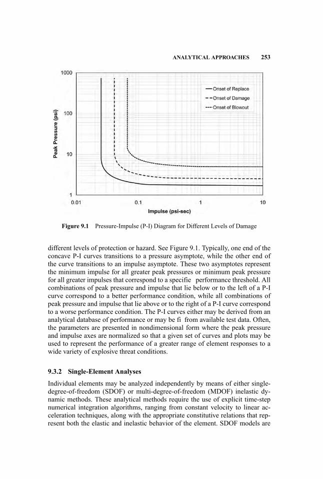
ANALYTICAL APPROACHES 253
Figure 9.1 Pressure-Impulse (P-I) Diagram for Different Levels of Damage
different levels of protection or hazard. See Figure 9.1. Typically, one end of theconcave P-I curves transitions to a pressure asymptote, while the other end ofthe curve transitions to an impulse asymptote. These two asymptotes representthe minimum impulse for all greater peak pressures or minimum peak pressurefor all greater impulses that correspond to a specifie performance threshold. Allcombinations of peak pressure and impulse that lie below or to the left of a P-Icurve correspond to a better performance condition, while all combinations ofpeak pressure and impulse that lie above or to the right of a P-I curve correspondto a worse performance condition. The P-I curves either may be derived from ananalytical database of performance or may be fi from available test data. Often,the parameters are presented in nondimensional form where the peak pressureand impulse axes are normalized so that a given set of curves and plots may beused to represent the performance of a greater range of element responses to awide variety of explosive threat conditions.
9.3.2 Single-Element Analyses
Individual elements may be analyzed independently by means of either single-degree-of-freedom (SDOF) or multi-degree-of-freedom (MDOF) inelastic dy-namic methods. These analytical methods require the use of explicit time-stepnumerical integration algorithms, ranging from constant velocity to linear ac-celeration techniques, along with the appropriate constitutive relations that rep-resent both the elastic and inelastic behavior of the element. SDOF models are

254 STRUCTURAL SYSTEMS DESIGN
inherently simple, and the accuracy of the response calculation depends on theapproximations that are used to characterize the dynamic response of the ele-ment. MDOF models may be significantl more complex and may be developedusing finit element methods (FEM) to derive the mass and stiffness matrices.While it is permissible to consider damping effects, these effects are generallysmall in comparison to the large inelastic response that may result from blastloading and are often neglected.
SDOF SDOF methods are adequately described in a variety of structuraldynamics textbooks (Biggs 1964) and U.S. Army Technical Manuals (UnifieFacilities Criteria Progam 2008b). This approach is based on solving the equationof motion for a spring-mass systemwith a nonlinear resistance function using nu-merical integration. The approximate design methods are based on a Rayleigh-Ritz approach for which representative shape functions for the fl xural mode areassumed and used to calculate the effective mass, effective stiffness, and effectiveloading function.When the loading pulse is very short relative to the period of thedynamic system, the initial velocity may be approximated as impulse divided bythe effective mass, and the kinetic energy of the system can be equated to the areaunder the force-displacement resistance function. This provides a closed formedrelationship between the required ultimate resistance (Rm), the applied impulse(I), the frequency of the dynamic system (ω) and the allowable ductility (µ).
Rm = Iω/(2µ − 1)0.5
The accuracy of these approximate approaches depends on selecting the ap-propriate SDOF system to represent the governing failure mechanism of the ele-ment. While this approach is most commonly used for the design and analysis ofelements that are subjected to blast loading, it requires considerable experienceto make sure a critical failure mechanism is not overlooked. Typically, fl xuralmodes of response are represented by the SDOF models; however, direct shearand instability may prove to be more critical response characteristics for short-standoff detonations and for axially loaded columns. The dynamic loads that maybe applied to SDOF analyses of individual structural elements may be based ontributary areas or may be derived from the dynamic reactions of the secondaryelements that frame into a primary element. The application of dynamic reac-tions from subsidiary elements accounts for the frequency of response and lim-iting capacity of the subsidiary elements, but must also include the appropriateamount of mass associated with the subsidiary element response. The dynamicreaction forces from a series of subsidiary element analyses may be convertedinto an equivalent dynamic load by equating the work performed by the individ-ual reactions through a representative deformation to the work performed by theequivalent SDOF response motion. Therefore, if SDOF analyses are performedfor individual secondary beams or purlins, the calculated reaction forces at ev-ery time-step may be multiplied by the shape function amplitude of the primarybeam or girder at the location of their connections. If this quantity of work is
ANALYTICAL APPROACHES 255
divided by the integral of the shape function over the span, the resulting quantityis the effective uniform load at the corresponding time-step that is applied overthe entire span.
MDOF MDOF analyses may be performed using a variety of dynamic re-sponse analysis software programs; however, all analyses must be performedat a sufficientl short time-step to guarantee numerical stability, to resolve thefrequency content of the model, and to accurately represent all potential modesof failure. Nonlinear dynamic finit element analyses provide the most compre-hensive means of determining the self-consistent stiffness and inertial properties,the limiting plastic limits, and the governing failure mechanisms. Furthermore,nonlinear geometric algorithms provide the means to include the destabilizingP-Delta effects due to the coupling of the large lateral transient deformationsand the static gravity loads. MDOF models accurately represent the spatial dis-tribution of dynamic pressures and dynamic reactions from subsidiary elementanalyses without having to generate an equivalent dynamic load.
9.3.3 Structural Systems Response
SDOF responses and MDOF models of individual elements do not account forthe interaction between interconnected elements, the phasing of their responses,or the fl xibility of the actual boundary conditions. These simplifie approachesrely on engineering judgment for the selection of approximate boundary con-ditions, such as soft springs and additional mass. As a result, the idealizationsrepresented by SDOF and MDOF analyses of individual structural elements donot accurately account for the dissipation of energy as the entire structure isdeformed and suffers damage. Structural system response calculations includethe relative fl xibility and strength of the interconnected structural elements andprovide a more accurate distribution of blast loading. Most importantly, how-ever, structural system analyses consider the phasing of the responses betweenthe different structural elements. Often, the region of greatest interest is mod-eled in greater detail, while the rest of the structure is more coarsely represented.This allows the analyst to dedicate the greatest computational resources to theresponse of critical details. However, as with all dynamic response analyses, thetransition from coarse representations to more detailed models must be gradualso as not to generate spurious results.
9.3.4 Explicit Dynamic Finite Element Analyses
Explicit dynamic finit element methods require sufficien modeling resolutionand short enough time-step to capture the high-frequency characteristics of theshock wave loading and structural response. Explicit formulations of the equa-tions of motion express the displacement at a given time-step tj + 1 (where theindices j represent the increments or steps in time for the duration of the responseanalysis) in terms of displacements, velocities, or accelerations at previous
256 STRUCTURAL SYSTEMS DESIGN
time-steps. This approach captures the high-frequency effects of the shock load-ing and easily allows for both material and geometric nonlinear effects; however,all explicit formulations have a critical time-step, above which the solution be-comes numerically unstable. The critical time-step is related to the wave speed ofthe material and the least dimension of the finit element model. The equation ofmotion is therefore solved at each node, using the current geometry and materialproperties at that location and point in time.
An implicit formulation of the equations of motion expresses displacementof each node at a given time-step tj + 1 in terms of all the displacements, ve-locities, or accelerations at that time-step tj + 1. The equations of motion for theentire system must be solved simultaneously; this is usually done using matrixmethods and is a very efficien way of calculating the response of linear elasticsystems. For nonlinear dynamic systems, however, an explicit formula (predic-tor) is usually used to estimate the response at the end of each time-step, and thisis followed by one or more corrections to improve the results. Such an approachis sometimes very inefficient Furthermore, even for elastic analysis, if the shockor high-frequency response of the system is needed, the time-step must be madesufficientl small to capture such effects while avoiding undue numerical damp-ing. Implicit schemes are least efficien in such cases.
Given the complexity of using explicit dynamic finit element methods, greatcare needs to be exercised to achieve sufficien accuracy. Verificatio and vali-dation of both the software and the analyst are critical to the successful comple-tion of high-fidelit first-principl calculations. Comparison of analysis methodsversus physical test data is one method for validating computational tools andapproaches. Benchmarking versus known analytical solutions or against othersoftware packages provides further confidenc in software and methods. Unlessestablished methods are used based on validation exercises, finit element meth-ods need to be checked with grid refinemen calculations to determine whetherthe model has sufficien resolution. Fine resolution and detailed models are noguarantee of accurate results. Accurate representation of material response, suf-ficien physical extent of the computational model, and proper boundary condi-tions are critical to calculating accurate results.
9.4 PROGRESSIVE COLLAPSE
The protective design of structures is often referred to as threat-dependent orthreat-independent. In one case, a structure is designed to provide a specifielevel of performance in response to a specifi design basis threat, while in theother, the structure is designed to be insensitive to local damage resulting fromunforeseen extraordinary events. In many cases, the uncertainty of the maxi-mum credible threat or the inability to accurately characterize the performancein response to explosive loading requires both approaches to be applied to thedesign. While the threat-dependent approach is related to the design basis threats,the threat-independent methods evaluate the potential for an initiating event to
PROGRESSIVE COLLAPSE 257
precipitate a broader extent of collapse. The prevention of progressive collapsemay therefore be achieved through the hardening of key structural elements inorder to preclude the initiating event, through the provision of ductile redundantload paths, or through compartmentalization that permits local failure to occurwithout endangering adjoining structural elements. In all cases, considerationmust be given to both global ductility demands that involve all elements of theframing system and local ductility in the vicinity of the initiating damage.
The insensitivity to local failure, often referred to as robustness, is a propertyof the structure, and is independent of possible causes of initial local failure.Where specifi threats are not prescribed, or for structures that are deemed lowrisk, an assumed extent of initial local failure and assumed extent of damageto the remaining structure may be prescribed. For these structures, element-to-element connectivity, minimum tie forces, the elimination of nonductile failuremechanisms, and enhanced stability requirements may improve the structure’srobustness. If the structural members and connections can develop these mini-mum tie forces, which vary with construction type and location in the structure,the structure will be held together in the event local damage disrupts the primaryload paths. The purpose of the horizontal and vertical ties is to enhance conti-nuity and ductility, and to develop alternate load paths in the structure. Internaland peripheral horizontal ties are typically provided, along with ties to externalcolumns and walls. The extent of tie force requirements may either be prescribedor calculated, starting with an assumed damage pattern. The alternate load pathrequirements, also termed “bridging requirements,” may be determined using dy-namic nonlinear analytical methods and known material damage limits, or maybe approximated using equivalent static elastic analysis methods with nominalmaterial damage criteria. The level of conservatism may be varied depending onthe level of approximation or the risk assessment for the structure.
Where the characteristics of the structure make bridging impractical, localhardening of key elements or the introduction of structural fuses may be intro-duced into the structure to either prevent the initial damage or defin a limitedzone of collapse. For these types of structures, the level of specifi local resis-tance for key elements or the zones of limited collapse must be defined
Where a threat and risk assessment quantifie the hazards to which a struc-ture may be subjected, specifi initiating events may be prescribed, and the per-formance of the structure may be calculated. Nonstructural protective measuresmay be developed to deny access to key structural members, or details and sac-rificia elements may be introduced to isolate the critical components. For thisperformance-based approach, the structural system redundancy and element ca-pacities would be designed to resist these initiating events or resist the progres-sion of damage or collapse. The increased resistance is therefore based on a pre-scribed set of actions and a permissible extent of resulting damage. The intensityof the initiating actions and the permissible response limits may be specifie inthe security performance criteria for the structure. The analytical methods thatdemonstrate the behavior of the structure must accurately represent the dynamicnature of the event and the damage-state behavior of the structural materials.
258 STRUCTURAL SYSTEMS DESIGN
Regardless of whether local hardening, bridging over a damaged structure, orcompartmentalization is used, a post-event stability analysis of the structural sys-tem must be performed.
For blast-resistant design, a threat must be identifie in order for the initialstate of damage and the residual capacity of the structure to be determined. Thisapproach is similar to that of performance-based seismic design codes for whichthe engineer selects the hazard (event) and the desired performance, such as lowlevels of damage (immediate occupancy), in response to a small earthquake andlife-safety protection (damage short of complete collapse) in response to an ex-treme event. Either the structural elements must be designed to resist the spec-ifie threat and maintain load-carrying capacity, or a finit extent of localizeddamage may be permitted, as long as the damaged structure is still capable ofpreventing a progression of collapse. This corresponds to the “extreme event” inresponse to which the structure must remain standing for life safety and evacua-tion of the occupants.
9.4.1 European Guidance
In the Euro-Norm EN 1991-1-7 (British Standards Institute 2006), the strategiesfor preventing collapse consider two different approaches: strategies based onidentifie accidental actions and strategies based on limiting the extent of local-ized failure. The strategies based on accidental actions consider designing thestructure to have sufficien minimum robustness, protective measures that pre-vent the action or reduce its effects, or designing the structure to resist the effectsof the action. The strategies based on limiting the extent of localized failure ad-dress the “threat-independent” prescriptive approaches for robustness, such asenhanced redundancy through alternate load paths, key element designs to with-stand notional accidental action, and prescriptive rules for integrity and ductility.
However, the criteria for protection are specifi to the project and are de-termined through consultation with the client and the relevant authority. Sincestrategies based on unidentifie accidental actions cover a wide range of possi-ble events, the means to prevent progression of collapse are typically based onlimiting the extent of localized failure. The magnitudes of accidental actions thatare identified as in the case of internal explosions and impact, are specifie inthe EuroNorms. In some cases where there is no risk to human life and whereeconomic, social, or environmental consequences are negligible, the completecollapse of the structure caused by an extreme event may be acceptable.
9.4.2 U.S. Guidance
All current U.S. Guidance documents are based on the U.K. standards that werebased on the partial collapse of the Ronan Point apartment house. These stan-dards extrapolated from the behavior of a panelized precast structure to developprescriptive and performance-based guidelines for other forms of construction.Similar requirements form the basis for the most recent Building Code of the
PROGRESSIVE COLLAPSE 259
City of New York (New York City Department of Buildings 2008), the 2008 Sup-plement to the International Building Code (International Code Council 2008),and the U.S. Department of Defense’s UFC 4-023-03 (Unifie Facilities Cri-teria 2008a). Since these approaches all rely on catenary action, the structuraldetailing must consider connections that are able to undergo significan inelasticrotations while sustaining large tensile axial loads.
Since the alternate path method is inherently dynamic and inelastic, theoptimal analytical approach considers material and geometric nonlinearity andinertial effects. While the analysis of dynamic systems may be performed usingimplicit or explicit numerical integration algorithms, the introduction of materialand geometric nonlinearity complicates the analysis. Implicit schemes requirethe reformulation of the stiffness matrix whenever properties are significantlaltered, and this can become computationally inefficien when significan extentsof inelasticity or catenary behavior are introduced. Explicit schemes requiresmall enough time-steps to ensure numerical stability, and this too may becomecomputationally inefficient Furthermore, unless the beam-column joints andconnections are explicitly modeled, their behavior must be approximated withequivalent nonlinear rotational and translational springs. The force displacementrelations for these equivalent nonlinear springs are best determined by perform-ing comprehensive component analyses of specifi joints, as was done for theanalysis of the Deutsche Bank Building for the World Trade Center BuildingPerformance Study (Federal Emergency Management Agency 2002).
The most recent version of UFC 4-023-03 (UFC, 2008a) proposes a simplifieprocedure that is based on the approaches established for Seismic Rehabilitationof Existing Buildings (American Society of Civil Engineers 2007). A ductilematerial that develops significan deformation following yield, over which theforce is either constant or increasing, is said to exhibit deformation-controlledbehavior. Alternatively, a brittle material that experiences a steep reductionin capacity following limited inelastic deformation exhibits force-controlledbehavior. The representations of structural behavior that are reported in ASCE41-06 are considered to be reasonable for the evaluation of damage-state perfor-mance of buildings. Although simplification to the dynamic inelastic responseanalyses reduce the extent of computational resources needed to calculate theperformance of the structure following the removal of a key element, thesesimplifie methods require detailed guidance in order to capture all reasonablefailure mechanisms. UFC 4-023-03 offers two simplifie static analysis proce-dures, linear static procedure (LSP) and nonlinear static procedure (NSP), asalternatives to the nonlinear dynamic procedure (NDP) approach. These sim-plifie approaches allow the use of commercially available structural analysissoftware that is readily available in structural design offices The simplifying ap-proximations allow the analyst to apply load factors to static analyses in order toaccount for the missing dynamic effects, and provide the means to interpret theresults of linear analyses to account for the material and geometric nonlineari-ties. Since the NDP is the most accurate representation of the structural responseto an initial state of damage, there is little ambiguity to the interpretation of the

260 STRUCTURAL SYSTEMS DESIGN
calculated results. Correspondingly, all approximate methods are necessarilyconservative, and a more representative analytical understanding will allow thedesigner to achieve a specifie level of robustness using a wider variety of struc-tural options. The use of the simplifie LSP is restricted to buildings with regularframing plans, which are define as irregularity limitations. Both approximatemethods were calibrated to nonlinear dynamic analysis to establish simplifiesystem-dependent factors that account for the anticipated dynamic response.
The LSP may be used wherever structural irregularities and demand capac-ity ratios conform to prescribed limitations. For the LSP, the structural modelis analyzed in response to both deformation and force-controlled actions. Theactions applied to the tributary areas above the removed key element are am-plifie to account for the inertial effects associated with the sudden removal ofthe column, and a concurrent lateral load is applied individually to each faceof the structure to evaluate stability. The LSP may still be used if the structuralframing is irregular, provided the calculated demand/capacity ratios (DCR) areless than or equal to 2.0; otherwise the NSP must be used. Once the accept-able use of the LSP is determined, the potential for disproportionate collapseis calculated using component or element demand modifier (m-factors) in anapproach that is similar to that of ASCE 41-06. M-factors are tabulated for dif-ferent types of structural systems and details for different levels of damage-stateperformance. These m-factors are used to determine both the Dynamic IncreaseFactors and the maximum acceptable forces for deformation-controlled actions.The expected material strength and the specifie material strength respectivelydefin material properties for deformation-controlled and force-controlled analy-ses, and the expected component strength (QCE) and lower bound estimate of thecomponent strength (QCL) respectively defin action capacities for deformation-controlled and force-controlled analyses. QUD is define as the deformation-controlled action, from linear static model; QUF is the force-controlled action,from linear static model; and � is the strength-reduction factor from the appro-priate material-specifi code.
� m QCE ≥ QUD deflection-controlle criteria�QCL ≥ QUF force-controlled criteria
The use of the NSP is not restricted by either irregularity or DCR lim-itations. The actions applied to the structure for the NSP are the same forcalculating displacement-controlled and force-controlled responses; however,the force-displacement behavior of all structural components must be explicitlymodeled, including connections wherever they are weaker or less ductile thanthe connected components or the fl xibility of the connection produces morethan a 10% change in the connection forces or deformations. Tabulated plasticrotation angles, as in ASCE 41-06, are used in the NSP to determine theDynamic Increase Factors; the deformation limits determine compliance fordeformation-controlled actions, and the lower bound estimate of the componentstrength determines compliance for force-controlled actions.

REFERENCES 261
While the UFC relies on the best information available, based on seismicresearch, the justificatio for the specifie factors and procedures requires rig-orous experimental and analytical study. Furthermore, the performance of ac-tual structural details for the different structural materials and systems requiresextensive analytical research and development. Although simplifie proceduresmust conservatively represent inelastic material properties and large displace-ment mechanics, there is little justificatio for overly precise procedures to ap-proximate the effects of dynamics and nonlinear behavior. Furthermore, the cor-relation between the simplifie analytical representation of structural behaviorand the actual performance of structural components undergoing large defor-mations requires significan testing and analysis. Even the use of conventionalunderstrength factors, � factors, may be questioned for the regime in which ma-terials will be severely distorted.
REFERENCES
American Society of Civil Engineers. 2007. Seismic Rehabilitation of Existing Buildings(ASCE 41-06). New York: American Society of Civil Engineers.
ASTM. 2003. Standard Practice for Specifying an Equivalent 3-Second Duration DesignLoading for Blast Resistant Glazing Fabricated with Laminated Glass (ASTM F2248).West Conshohocken, PA: ASTM International.
ASTM. 2007. Standard Practice for Determining Load Resistance of Glass in Buildings(ASTM E1300). West Conshohocken, PA: ASTM International.
Biggs J. M. 1964. Introduction to Structural Dynamics. New York: McGraw-Hill BookCompany.
British Standards Institute. 2006. Eurocode 1: Actions on Structures—Part 1–7: GeneralActions—Accidental Actions (EN 1991-1-7:2006). London: British Standards Institute.
Federal Emergency Management Agency. 2002. World Trade Center Building Per-formance Study: Data Collection, Preliminary Observations and Recommendations(FEMA 403). Washington, DC: Federal Emergency Management Agency, Departmentof Homeland Security.
Hyde D. W. 1992. CONWEP, Conventional Weapons Effects (USAEWES/SS-R).Vicksburg, MS: U.S. Army Engineer Waterways Experiment Station.
International Code Council. 2008. Supplement to the International Building Code.Washington, DC: International Code Council.
Kingery C. N. and G. Bulmash. 1984. Airblast Parameters from TNT Spherical AirBurst and Hemispherical Surface Burst (ARBRL-TR-02555, AD B082713). AberdeenProving Ground, MD: U.S. Armament Research and Development Center, BallisticResearch Laboratory.
New York City Department of Buildings. 2008. Supplement to the Building Code ofthe City of New York, Local Law No 76 Effective December 6, 1968. New York:Department of Buildings.
Oswald C. J. 2005. Component Explosive Damage Assessment Workbook (CEDAW)Methodology Manual V1.0 (02-0752-001), San Antonio, TX: Baker Engineering andRisk Consultants, Inc.

262 STRUCTURAL SYSTEMS DESIGN
Protective Design Center. 2006.Methodology Manual for the Single-Degree-of-FreedomBlast Effects Design Spreadsheets (SBEDS) (PDC-TR-06-01), Omaha, NE: U.S. ArmyCorps of Engineers, Protective Design Center.
Unifie Facilities Criteria Program. 2002. Design and Analysis of Hardened Structuresto Conventional Weapons Effects (UFC 3-340-01). Washington, DC: Department ofDefense, Unifie Facilities Criteria Program.
. 2008a. Design of Buildings to Resist Progressive Collapse (UFC 4-023-03).Washington, DC: Department of Defense, Unifie Facilities Criteria Program.
. 2008b. Structures to Resist the Effects of Accidental Explosions (UFC 3-340-02). Washington, DC: Department of Defense, Unifie Facilities Criteria Program.

10 Building Envelope and Glazing
Eve Hinman and Christopher Arnold
For an explosion outside a building, the exterior envelope is the critical line of de-fense that separates the people, operations, and contents inside the building fromthe air-blast effects outside the building. Unfortunately, for most standard build-ing types, the building envelope is ill-suited to resisting air-blast loads, which areenormous and which act directly on the surface area of the exterior envelope inthe out-of-plane direction.
In this chapter, some of the key concepts needed to optimize the design ofthe exterior envelope to mitigate explosion effects are presented. A variety ofwall and window types are considered, as well as doors and louvers. Roof andfoundation systems are also addressed.
10.1 DESIGN INTENT
The primary design objective for the exterior envelope of most standard buildingtypes, is to mitigate the hazard of flyin debris generated by failed exterior walls,windows, and other components, to reduce casualties and business disruption andfacilitate rescue and evacuation efforts.
Other objectives are to design the exterior envelope to:
� Fail in a way that does not initiate progressive collapse� Keep the air blast outside the building to the best of its ability
10.1.1 Life Safety
Impact of flyin debris entering a building causes laceration and blunt traumainjuries, and potentially fatalities. Once the exterior envelope is pierced and theair blast enters the building, injuries such as eardrum rupture, lung collapse, andblunt trauma and concussion due to being thrown against objects are the dom-inant injury modes. Impacts due to internal nonstructural damage to partitionsand ceiling, light fixture and equipment components and falling furniture arealso a hazard.
263
Handbook for Blast-Resistant Design of Buildings Edited by Donald 0. Dusenberry
Copyright 0 2010 by John Wiley & Sons, Inc. All rights reserved.

264 BUILDING ENVELOPE AND GLAZING
Although it is cost-prohibitive to eliminate all these hazards, it is possible toreduce the risk to a level that is acceptable through informed design decisions.
10.1.2 Emergency Egress and Facilitating Search and Rescue
The building exterior envelope design may be optimized to make it easier forpeople to get out and for emergency responders to enter safely.
After an explosive event, the debris created by the failed exterior envelopecan exacerbate casualties by reducing the efficien y of evacuation and rescueoperations. Some examples of this are:
� Internal debris can cause occupants to become trapped in rubble piles.� Exterior debris can block emergency exits.� Debris along egress paths can cause delays and additional injuries.� Exterior falling fragments post-event trigger safety precautions for emer-gency operations, which can significantl delay rescue, thereby putting theinjured at greater risk.
� Toxic dust or fumes generated by debris may have long-term health ramifications.
10.1.3 Critical Functions (Protecting Equipment and Business Processes)
Even at low pressures, air blast that enters the building can cause extensive non-structural damage to interior partitions and suspended ceilings. The resultinginternal disarray can cause extensive business disruption. Even if the damagesare repairable, total cost required to return the building to pre-event functionalitymay exceed the replacement cost of the building.
Sensitive mechanical parts of critical equipment can be disabled by air blastor flyin debris that enters the building through the exterior envelope. An interiorbaffl wall may be used to dissipate the energy of the air blast by forcing it tochange direction two or more times before it reaches the equipment. Some otheroptions are to use storm louvers or forced-entry-resistant louvers, which havea chevron cross section which are able to perform a similar function. Louverattachments into the structure are to be designed to resist the capacity of thelouver to ensure that the louver fails before the connections. In some cases, acatch system using a grate securely fastened behind the louver may be used toprevent impact into delicate equipment components.
Critical equipment placed on the roof will be less vulnerable to a ground levelexplosion than equipment at or below street level. For roof equipment, a hard-ened wall with roof may be used for protection. However, for this solution, notethat if the wall fails, the impact of debris may have a more detrimental effect thanusing lightweight housing that is not blast-resistant.
It is recommended that the transformer be placed away from vulnerable areas,for instance in a parking lot, near the loading dock, or under the sidewalk. Inside

DESIGN APPROACH 265
the building in a protected location is preferred. The switchgear room is to beseparated to the extent practical from the transformer(s), the generators, and anyother backup systems, such as an uninterruptible power supply (UPS) or batter-ies, to improve the chances of retaining at least emergency functions in the eventof an explosive attack. In addition to separation, redundancy of critical systemsis highly recommended for higher-risk buildings. An example of this is placingone set of generators on one side of the building, and another set on the otherside of the building to create redundancy.
10.2 DESIGN APPROACH
For buildings with a low to moderate risk of explosive attack, the designapproach is to firs design the building exterior envelope for conventional loads,and then to evaluate the response to explosive loads. If the design team isproperly consulted when key decisions are made during the concept phase, thenthe modification required to meet explosive load requirements can be addressedefficientl . This approach ensures that the design meets all the requirements forgravity and natural hazards, in addition to air-blast effects, and is effective forbuildings where explosion effects are a secondary concern.
Take note that some features that are beneficia for blast resistance diminishperformance for other loads, if not properly integrated. For example, using aplastic coating that emits toxic fumes in the event of a fir may not be a goodsolution for enhancing the blast performance of an exterior wall, since fir is amore common hazard than terrorist attack.
Another example that presents a potential conflic between the seismic designand blast design is that increased mass generally increases the design forces,whereas for explosion loads, mass generally improves response. This is becauseof the highly impulsive nature of explosive loads. Heavy structural componentshave longer periods of vibration so that, by the time the mass,M, is mobilized andthe structural component begins to move with a velocity, V , the load or impulse,I, has been removed. In mathematical terms, the kinetic energy, KE =MV2/2, ormomentum, MV , imparted to the structural component is directly proportionalto impulse and inversely proportional to the mass: i.e., KE = MV2/2 = (Mv)2/(2M) = I2/(2m). In this situation, careful coordination between the blast consul-tant and the structural engineer is needed to provide an optimized response thataccounts for both loading cases.
Good antiterrorism design is a multidisciplinary effort, requiring the con-certed efforts of the architect, structural engineer, security professional, and theother design team members. For instance the passive protection provided byeffective building design needs to be balanced with the active or operationalsecurity measures implemented (e.g., guards, cameras, dogs, sensors, magne-tometers). It is critical that these two sets of measures complement and supportone another. In particular, the size weapon that is considered at the perimeterand at the exterior envelope is a function of the size weapon that is able to be
266 BUILDING ENVELOPE AND GLAZING
easily detected through operational security measures. Like protective design,security needs to be implemented early in the design to be effective. Linesof sight; lighting and placement of cameras along the exterior envelope; andlocation, number and type of entrances provided are examples of security issuesto be addressed early in design with the architect, since they potentially affectthe design threat to be used.
The envelope system is to be designed by keeping in mind the concepts ofbalanced or capacity design (see Section 10.2.3) and ductile response. Ductilesystems are able to absorb energy through inelastic fl xural deformation. Sys-tems that fail in a brittle manner through shear are to be avoided. By permittinglimited exterior envelope damage that does not significantl increase the haz-ard to the majority of the occupants, it is possible to design more cost-effectivesystems that absorb energy through deformation, and transmit lower forces intothe connections and supporting structure, thus reducing the potential for moreserious structural failures.
Perhaps the simplest analytical method is to use a pressure-impulse, or P-I,diagram, in which various damage levels for a component with a given resis-tance are expressed as curves, and the axes are peak pressure and impulse. Byplotting the pressure and impulse acting on the system, you can estimate thelevel of damage to the exterior envelope component and compare it with allow-able limits. These curves may be based on explosive tests or on the output froma semi-empirical or a single-degree-of-freedom system. The limitation of thesetools is that they are based on constant parameters for the component under con-sideration. If the component that is being investigated differs in any way, someextrapolation or interpolation between charts is needed.
Typically, simplifie or single-degree-of-freedom (SDOF) methods used forthe design of structural components may be used for the exterior envelope (Uni-fie Facilities Criteria Program 2008). For these systems, the component time-dependent peak deflection X(t), is evaluated by modeling the component as alumped mass, M, so that the inertia force is MA(t) where A(t) is the accelerationor second derivative of X(t). The resistance is provided by a spring, R(x), whichhas a linear elastic fl xural stiffness, K, and a ultimate fl xural resistance of Ru.The loading is modeled as a time-dependent function, F(t). For a system initiallyat rest, the resulting equation of motion is:
MA(t)+ R(x) = P(t)
where: R(x)=KX(t) when X(t) is less than or equal to the maximum elastic limitdisplacement Xe and
R(x) = Ru when X (t) > Xe
In these expressions, M and R, and P are “equivalent” values which rep-resent the portion of the mass, resistance, and loading that is participating inthe displacement of the member, and which provide a natural frequency and
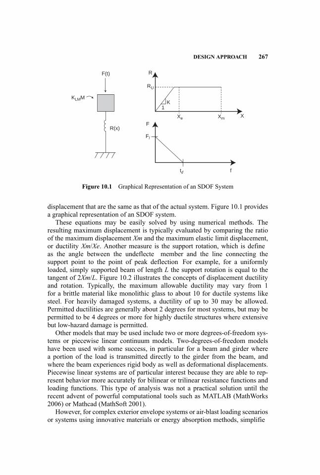
DESIGN APPROACH 267
R
K
Xe Xm X
1
F
F(t)
R(x)
KLMM
Fl
td f
RU
Figure 10.1 Graphical Representation of an SDOF System
displacement that are the same as that of the actual system. Figure 10.1 providesa graphical representation of an SDOF system.
These equations may be easily solved by using numerical methods. Theresulting maximum displacement is typically evaluated by comparing the ratioof the maximum displacement Xm and the maximum elastic limit displacement,or ductility Xm/Xe. Another measure is the support rotation, which is defineas the angle between the undeflecte member and the line connecting thesupport point to the point of peak deflection For example, for a uniformlyloaded, simply supported beam of length L the support rotation is equal to thetangent of 2Xm/L. Figure 10.2 illustrates the concepts of displacement ductilityand rotation. Typically, the maximum allowable ductility may vary from 1for a brittle material like monolithic glass to about 10 for ductile systems likesteel. For heavily damaged systems, a ductility of up to 30 may be allowed.Permitted ductilities are generally about 2 degrees for most systems, but may bepermitted to be 4 degrees or more for highly ductile structures where extensivebut low-hazard damage is permitted.
Other models that may be used include two or more degrees-of-freedom sys-tems or piecewise linear continuum models. Two-degrees-of-freedom modelshave been used with some success, in particular for a beam and girder wherea portion of the load is transmitted directly to the girder from the beam, andwhere the beam experiences rigid body as well as deformational displacements.Piecewise linear systems are of particular interest because they are able to rep-resent behavior more accurately for bilinear or trilinear resistance functions andloading functions. This type of analysis was not a practical solution until therecent advent of powerful computational tools such as MATLAB (MathWorks2006) or Mathcad (MathSoft 2001).
However, for complex exterior envelope systems or air-blast loading scenariosor systems using innovative materials or energy absorption methods, simplifie

268 BUILDING ENVELOPE AND GLAZING
R
K
Xe Xm
X
L
Plastic Hinge
Xm = Peak Displacement
RU
Figure 10.2 Graphical Representation of the Concepts of Displacement Ductility andRotation
analysis is not sufficient In these cases, the engineer needs to use finite-elemennumerical time integration techniques and/or explosive testing to verify response.Again, nonlinear dynamic time history analysis is required to adequately modelthe system. Material models used for these programs are generally more sophis-ticated than the linear elastic perfectly plastic models used for simplifie anal-ysis. In this case, the material models provide a more realistic representationfor large deformation. Examples of computer codes on the market that are ca-pable of performing these types of computations include SAP2000/NonLinear(Computers and Structures 1990) and LS-DYNA (Livermore Software Technol-ogy Corp. 1999). There are also codes available to model the expansion of an airblast and its reflectio against the structure surface, which may be used to gen-erate the loads applied to the model using a software product such as CONWEP(Hyde 1988) or ATBLAST, a software product prepared by Applied ResearchAssociates.
The time and cost required to perform the analysis cannot be ignored in choos-ing computational methods. Because the design process may require iteration,the cost of analysis must be justifie in terms of benefit to the project and in-creased confidenc in the reliability of the results. In some cases, a simplifieapproach will be used for the preliminary design and a more sophisticated ap-proach, using finit elements and/or explosive testing, may be used for the finaverificatio of the design.
If testing has been performed for a similar system, it is necessary to obtain thetesting report and verify that the assumptions and finding are consistent withthe project requirements, prior to accepting testing in lieu of detailed analysis.In particular, check to make sure that the support conditions for the member are

DESIGN APPROACH 269
accurately represented. Also check to see that both the pressure and impulse areat least as large as what the design requires. If only the pressure or the impulsemeets criteria, some additional calculations will be needed to verify response.It is recommended that the testing be supplemented with pre- and post-analysis,using an advanced method such as finit elements.
Often, only a proof of concept design is provided by the blast engineer duringdesign. The fina blast design is the responsibility of the subcontractor imple-menting the design. A detailed set of specification is strongly recommendedto ensure that the design intent is met. Some of the requirements to consider,including in the specification for the exterior facade subcontractors, are:
� Provide performance-based design requirements for response.� Put all the blast requirements in a single location in the specifications ratherthan sprinkling them through the individual sections. This makes it easierfor everyone to keep track of these special requirements.
� Require the blast engineer’s approval of the subcontractor based on success-ful performance on similar projects.
� Require the subcontractor to submit blast calculations for review.
10.2.1 Response Criteria
Levels of damage to the exterior envelope may be described by these terms:minor, moderate, major, catastrophic. Qualitative descriptions of each damagelevel are given below as they pertain to the exterior envelope. Note that all thesedescriptions imply that there is little or no structural damage (i.e., all the damageis limited to the exterior envelope).
Minor: There is little if any damage. The exterior envelope may sustain somedamage, but virtually no failure. Damage may consist of cracked windows,failed sunshades still attached to the building, or permanent deformationof walls and window frames. Injuries may be expected, and fatalities arepossible but unlikely.
Moderate: Failure of the exterior envelope is confine to a localized area andis usually repairable. Hazardous window failure is limited to one face ofthe building. Injuries and possible fatalities are expected.
Major: Extensive exterior envelope damage and some roof damage are ex-pected. In this case, extensive fatalities are expected. Damage is usuallynot repairable.
Catastrophic: In this case, all or the majority of the exterior envelope has beenremoved.
Generally, moderate damage for the design basis threat is a reasonable goalfor new construction to meet life-safety objectives. For buildings that need to

270 BUILDING ENVELOPE AND GLAZING
remain operational during and after an event, or are designated as high risk,minor damage may be the more appropriate damage level.
Quantitative performance is usually evaluated by comparing the ductility (i.e.,the peak displacement divided by the elastic limit displacement) and/or supportrotation (the angle between the support and the point of peak deflection to em-pirically established maximum values that have been established by the militarythrough explosive testing. Maximum permissible values vary depending on thematerial and the acceptable damage level. Some criteria documents do providethe design values that need to be met.
10.2.2 Static versus Dynamic
A dynamic nonlinear approach is more likely to provide a design that meets thedesign constraints of the project than a static approach. Elastic static calcula-tions are likely to give overly conservative design solutions if the peak pressureis considered without the effect of load duration. By using dynamic calculationsinstead of static, we are able to account for the very short duration of the load-ing. In addition, the inertial effect included in dynamic computations greatly im-proves response. This is because by the time the mass is mobilized, the loadingis greatly diminished, enhancing response. Furthermore, by accepting that dam-age occurs, we are able to account for the energy absorption of ductile systemsthat occurs through plastic deformation. Finally, because the loading is so rapid,we are able to engage the enhanced material strength that often occurs with veryhigh strain rates.
10.2.3 Balanced Design
Balanced or capacity design philosophy for a building system refers to designsthat are controlled such that the failure of the weakest component in the systemresults in the least destruction. For a window system, for instance, it refers to thewindow glass failing at pressure levels that do not exceed those of the frame, an-chorage, and supporting wall system. If the glass is stronger than the supportingmembers, then the window is likely to fail with the whole panel entering intothe building as a single unit, possibly with the frame, anchorage, and the wallattached. This failure mode is considered more hazardous than one in whichthe glass fragments enter the building, provided that the fragments are designedto minimize injuries. By means of a damage-limiting approach, the damage se-quence and extent of damage are controlled.
10.2.4 Load Path
Load path in the exterior envelope generally refers to the transmission of loadfrom the member that presents the most surface area to the exterior (i.e., glasspane, panel, wall, slab) into the building structure. Connections and reactionforces, two of the more nontrivial parts of the path, are discussed below.
DESIGN APPROACH 271
Connections For the exterior facade, the connections include:
� The connection between the window glass and the window mullion, tran-som or frame
� The connection of the window mullion or transom and the window frame� The connection between the window frame and the wall� The connection between the wall and the structural frame
Connections are typically the least ductile elements in the exterior envelopesystem and the most prone to failure if not properly designed. The connectionsare required to enable the supporting elements to reach their ultimate fl xuralcapacity without failure. They also need to remain intact for the loads imposedby large inelastic deformations of the supporting members, which in turn cancause significan deformation of the connections.
Fasteners holding the window frame in the wall tend to be placed into tensionand shear as the window undergoes deformation. The wet glazing are put intoshear as a laminated glass pane begins to act as a membrane. As the mullion of aunitized system deforms, stresses are placed on the connections holding the twohalves of the mullion together.
The failure envelope of connections respondingto load combinations such astension and shear need to be considered as part of the design.
Although it seems as if window frame connections should be routinely de-signed to carry the ultimate loads transmitted by the window pane, this is not thecase. The window frame is designed to carry the design loads only. The capacityof the glass may be significantl higher than the design loads.
Reaction Loads (Ru versus Applied Load) Reaction loads may conservativelybe approximated by the static ultimate capacity of the loading element, and bysetting the load and strength factors for the connection design to 1.0. The loadfactor is set to 1 because we are assuming that the supported member has beenpushed to its capacity. The reaction load cannot be higher than the capacity of themember. Similarly, the strength factor is set to 1, again in recognition of the factthat we are letting the supporting member reach its ultimate capacity. Althoughthis may not seem conservative, it is, because we neglected the mitigating effectsof ductility and inertia on the system.
This approach is consistent with capacity or balanced design principles andis the best and most reliable. However, it can lead to designs that are not con-structible or affordable. If this is the case there are several approaches whichmay be considered:
� Use the average applied load instead of the peak load, because the edgeload along a panel transfers a load that varies with its peak value at thecenter point and decreases towards the ends. Often the peak value is given,but the average load along the length is less and is more representative ofthe loading on the anchors.
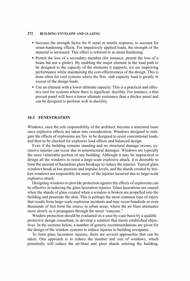
272 BUILDING ENVELOPE AND GLAZING
� Increase the strength factor for fl xural or tensile response, to account forstrain-hardening effects. For impulsively applied loads, the strength of thematerial is increased. This effect is referred to as strain hardening.
� Permit the loss of a secondary member (for instance, permit the loss of abeam but not a girder). By enabling the major element in the load path tobe designed to the capacity of the elements it supports, we are improvingperformance while maintaining the cost-effectiveness of the design. This isdone often for roof systems where the floo slab capacity load is greatly inexcess of the design loads.
� Use an element with a lower ultimate capacity. This is a practical and effec-tive tool for systems where there is significan ductility. For instance, a thinprecast panel will have a lower ultimate resistance than a thicker panel andcan be designed to perform well in ductility.
10.3 FENESTRATION
Windows, once the sole responsibility of the architect, become a structural issueonce explosive effects are taken into consideration. Windows designed to miti-gate the effects of explosions are firs to be designed to resist conventional loads,and then to be checked for explosive load effects and balanced design.
Even if the building remains standing and no structural damage occurs, ex-tensive injuries can occur due to nonstructural damages. Windows are typicallythe most vulnerable portion of any building. Although it may be impractical todesign all the windows to resist a large-scale explosive attack, it is desirable tolimit the amount of hazardous glass breakage to reduce the injuries. Typical glasswindows break at low pressure and impulse levels, and the shards created by bro-ken windows are responsible for many of the injuries incurred due to large-scaleexplosive attack.
Designing windows to provide protection against the effects of explosions canbe effective in reducing the glass laceration injuries. Glass lacerations are causedwhen the shards of glass created when a window is broken are propelled into thebuilding and penetrate the skin. This is perhaps the most common type of injurythat results from large-scale explosion incidents and may occur hundreds or eventhousands of feet from the source in urban areas, where the air blast attenuatesmore slowly as it propagates through the street “canyons.”
Window protection should be evaluated on a case-by-case basis by a qualifieprotective design consultant, to develop a solution that meets established objec-tives. In the sections below, a number of generic recommendations are given forthe design of the window systems to reduce injuries to building occupants.
To limit glass laceration injuries, there are several approaches that can betaken. One approach is to reduce the number and size of windows, whichpotentially will reduce the air-blast and glass shards entering the building,
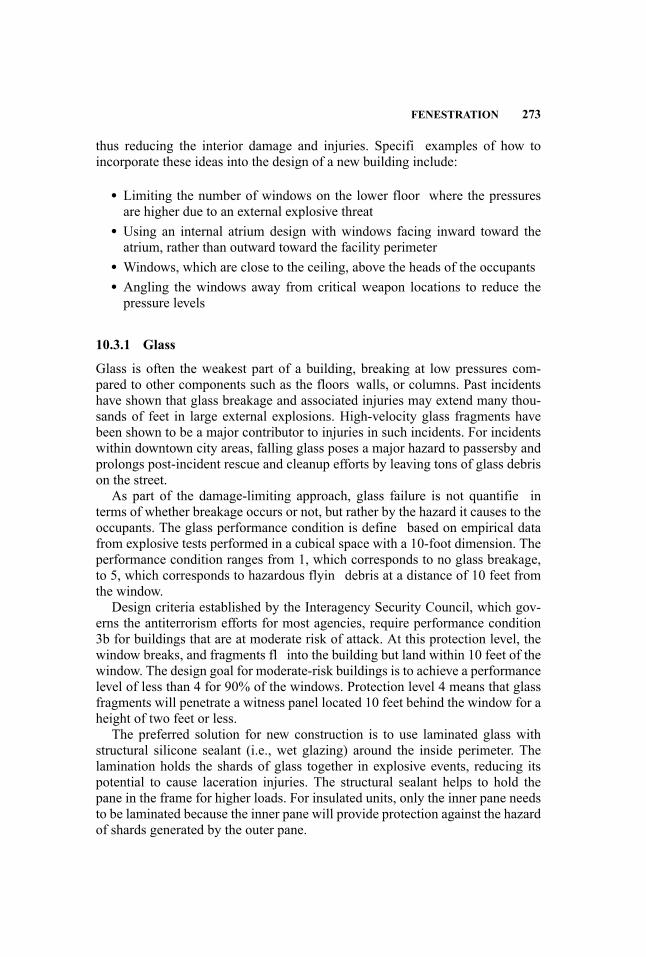
FENESTRATION 273
thus reducing the interior damage and injuries. Specifi examples of how toincorporate these ideas into the design of a new building include:
� Limiting the number of windows on the lower floor where the pressuresare higher due to an external explosive threat
� Using an internal atrium design with windows facing inward toward theatrium, rather than outward toward the facility perimeter
� Windows, which are close to the ceiling, above the heads of the occupants� Angling the windows away from critical weapon locations to reduce thepressure levels
10.3.1 Glass
Glass is often the weakest part of a building, breaking at low pressures com-pared to other components such as the floors walls, or columns. Past incidentshave shown that glass breakage and associated injuries may extend many thou-sands of feet in large external explosions. High-velocity glass fragments havebeen shown to be a major contributor to injuries in such incidents. For incidentswithin downtown city areas, falling glass poses a major hazard to passersby andprolongs post-incident rescue and cleanup efforts by leaving tons of glass debrison the street.
As part of the damage-limiting approach, glass failure is not quantifie interms of whether breakage occurs or not, but rather by the hazard it causes to theoccupants. The glass performance condition is define based on empirical datafrom explosive tests performed in a cubical space with a 10-foot dimension. Theperformance condition ranges from 1, which corresponds to no glass breakage,to 5, which corresponds to hazardous flyin debris at a distance of 10 feet fromthe window.
Design criteria established by the Interagency Security Council, which gov-erns the antiterrorism efforts for most agencies, require performance condition3b for buildings that are at moderate risk of attack. At this protection level, thewindow breaks, and fragments fl into the building but land within 10 feet of thewindow. The design goal for moderate-risk buildings is to achieve a performancelevel of less than 4 for 90% of the windows. Protection level 4 means that glassfragments will penetrate a witness panel located 10 feet behind the window for aheight of two feet or less.
The preferred solution for new construction is to use laminated glass withstructural silicone sealant (i.e., wet glazing) around the inside perimeter. Thelamination holds the shards of glass together in explosive events, reducing itspotential to cause laceration injuries. The structural sealant helps to hold thepane in the frame for higher loads. For insulated units, only the inner pane needsto be laminated because the inner pane will provide protection against the hazardof shards generated by the outer pane.
274 BUILDING ENVELOPE AND GLAZING
Annealed glass has a breaking strength that is about one-half that of heat-strengthened glass and about one-fourth that of tempered glass (Amstock 1997),thus reducing the loads transmitted to the supporting frame and walls. To reducereaction loads, it is sometimes advantageous to consider annealed glass. Thepreferred interlayer thickness is 60 mil (0.06 in) unless otherwise specifie bythe criteria. At a minimum, 30 mil is to be used.
To make sure that the components supporting the glass are stronger than theglass itself, we specify a window breakage strength that is high compared towhat is used in conventional design. The breakage strength in window designmay be specifie as a probability of the number of windows expected to breakat that load. For instance, when designing for conventional loads, it is typicalto use a breakage pressure corresponding to a probability of 8 breaks out of1,000. Where there is a high probability of extensive glass breakage, as in anexplosion incident, a pressure corresponding to 750 breaks out of 1,000 is used.Glass breakage strengths may be obtained from window manufacturers.
Smaller glass panes generally have higher capacities than larger panes. Con-sequently, smaller panes can cause significantl higher loads to be transmittedto the frames than larger panes. As a result, in blast-mitigating design, we avoidsmall panes. Also, since every size pane has a difference capacity, it is desirableto standardize the design as much as is practical.
There are several government-sponsored software products available for eval-uating the response of window glass for use on federal projects, including HAZL(U.S. Army Engineer Research and Development Center 2001), WINGARD,and WINLAC. These codes are made available to government contractors whohave government projects requiring this type of analysis. One approach thatis publicly available is described in the criteria by the U.S. military (UnifieFacilities Criteria Program 2007), using ASTM Standards (ASTM 2003,2004a). For those who are designing unique systems for specifi threats notcovered in criteria documents, it is recommended that the system be tested(ASTM 2001).
Glass block is generally not recommended because of the heavy projectilesthese walls may create due to failure at the mortar lines. However, blast-ratedglass-block products are available in which the glass blocks are framed by asteel grate system or other method.
The way in which the glass is supported into the exterior envelope can havean effect on the severity of the glass hazard. A brief summary of various types ofsupports is given below.Punched Windows: Punched windows (see Figure 10.3) often can be designed
efficientl to be less vulnerable than other window types because the frame isattached directly into the wall, which is generally of more robust construction.Strip Windows: Strip or ribbon windows (see Figure 10.4) generally consist
of alternating bands of glazing and opaque material constructed using precastpanels, poured concrete, or insulated metal panels. The opaque area concealsthe floo structure and is referred to as a “spandrel.” Ribbon windows have thinvertical metal framing separating the individual panes, and are supported by
FENESTRATION 275
Figure 10.3 Example of “Punched” Windows
the wall at the top and bottom. For this type of exterior facade, the spandrelsare attached to each floo level instead. The system is very economical and acommon facade type. To resist air-blast loads, steel angle kicker braces are oftenneeded to laterally support the bottom of the spandrel panel.Glass Curtain Wall: For this glazing type, a significan part of the building ex-
terior is covered with windows supported by aluminum or possibly steel framing.Figure 10.5 shows three variations of curtain wall system.
Figure 10.4 Example of Ribbon Windows, Showing Spandrel
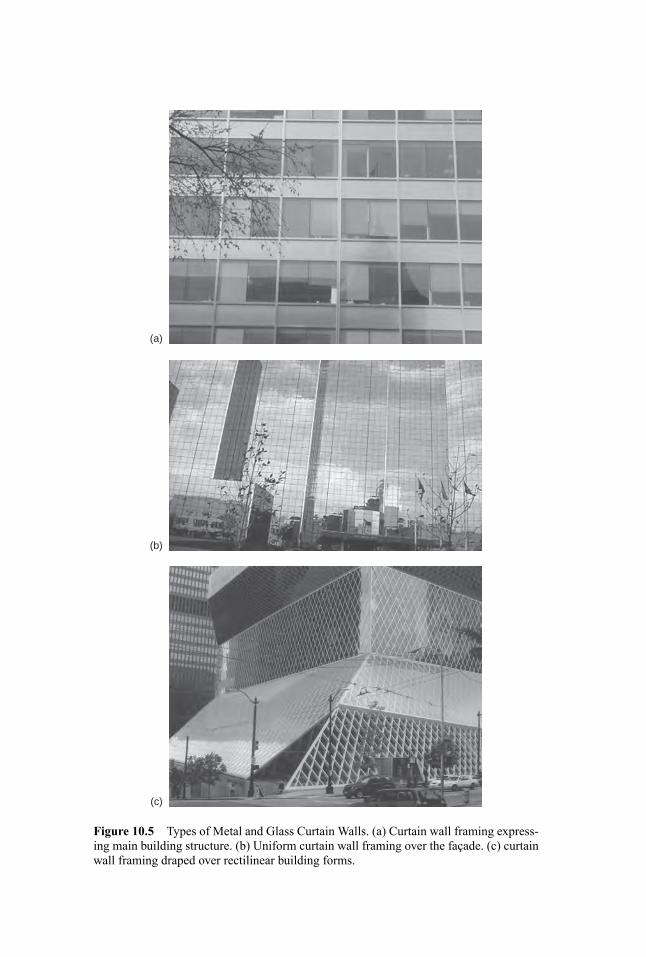
(a)
(b)
(c)
Figure 10.5 Types of Metal and Glass Curtain Walls. (a) Curtain wall framing express-ing main building structure. (b) Uniform curtain wall framing over the facade. (c) curtainwall framing draped over rectilinear building forms.
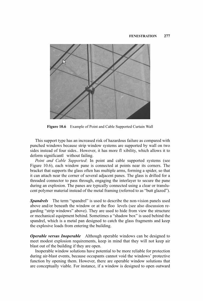
FENESTRATION 277
Figure 10.6 Example of Point and Cable Supported Curtain Wall
This support type has an increased risk of hazardous failure as compared withpunched windows because strip window systems are supported by wall on twosides instead of four sides.. However, it has more fl xibility, which allows it todeform significantl without failing.Point and Cable Supported: In point and cable supported systems (see
Figure 10.6), each window pane is connected at points near its corners. Thebracket that supports the glass often has multiple arms, forming a spider, so thatit can attach near the corner of several adjacent panes. The glass is drilled for athreaded connector to pass through, engaging the interlayer to secure the paneduring an explosion. The panes are typically connected using a clear or translu-cent polymer material instead of the metal framing (referred to as “butt glazed”).
Spandrels The term “spandrel” is used to describe the non-vision panels usedabove and/or beneath the window or at the floo levels (see also discussion re-garding “strip windows” above). They are used to hide from view the structureor mechanical equipment behind. Sometimes a “shadow box” is used behind thespandrel, which is a metal pan designed to catch the glass fragments and keepthe explosive loads from entering the building.
Operable versus Inoperable Although operable windows can be designed tomeet modest explosion requirements, keep in mind that they will not keep airblast out of the building if they are open.
Inoperable window solutions have potential to be more reliable for protectionduring air-blast events, because occupants cannot void the windows’ protectivefunction by opening them. However, there are operable window solutions thatare conceptually viable. For instance, if a window is designed to open outward

278 BUILDING ENVELOPE AND GLAZING
about a horizontal hinge at the sill, the window will tend to slam shut in anexterior explosion. If this type of design is used, the governing design parametermay be the capacity of the hinges and/or hardware.
The controlling design component for sliding operable windows (and glazeddoors) often is the supporting track. If possible, the track should be embedded inthe supporting structure to provide added out-of-plane support to the system.
Skylights/Courtyards Skylights in roof systems have the advantage of not be-ing subject to reflecte pressures fromexterior explosions at ground level. Also,skylights are required by building code to be designed using laminated glass,which is preferred for explosion-mitigating design. However, they do create afalling fragment hazard. Therefore, these should be designed with a catch sys-tem beneath, or designed to remain in the frame for the design air-blast load.Ideally, skylights should be placed as far from the weapon as possible, to keepthe pressures low.
For an atrium with an open courtyard in the center, the windows are protectedby the building on all sides, and the glass will be subject to indirect air-blastpressures in the event of an explosion outside the building exterior. Because atriaare protected on all sides, they may be designed for the reduced pressures from anexterior threat. These reductions in pressures can help significantl in reducingthe design requirements imposed by explosion loads.
Doors Glazed doors and glass panes above a door are to be designed usingthe same methods as for windows. Glazed doors tend to use tempered glass forsafety, in case of accidental breakage due to impact. As a result, they are high-strength and can complicate the design of the supporting system
10.3.2 Mullions/Transoms
The vertical frame members connecting adjoining windows are referred to asmullions. Horizontal members are termed transoms. These members may bedesigned in two ways. Either a static approach may be used, whereby thebreaking strength of the window glass is applied to the mullion, or a dynamicload may be applied, using the peak pressure and impulse values. A static ap-proach may be overly conservative because the designer using this approachassumes that the peak edge forces are sustained indefinitel , whereas in anexplosion the forces are of very short duration, and the supporting structurehas insufficien time to fully respond to the impulsive forces. Using this ap-proach, the mullion can become very deep and heavy, driving up the weightand cost of the window system. Figure 10.7 shows heavy mullions in an olderbuilding.
Sometimes cables or steel bars or tubes attached to the supporting structure areplaced behind the glass to prevent the laminated glass or glass with anti-shatterfil from entering the interior (Crawfordk, Lan and Dunn 2006).
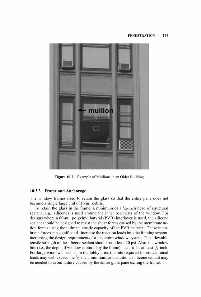
FENESTRATION 279
Figure 10.7 Example of Mullions in an Older Building
10.3.3 Frame and Anchorage
The window frames need to retain the glass so that the entire pane does notbecome a single large unit of flyin debris.
To retain the glass in the frame, a minimum of a 1/4-inch bead of structuralsealant (e.g., silicone) is used around the inner perimeter of the window. Fordesigns where a 60-mil polyvinyl butyral (PVB) interlayer is used, the siliconesealant should be designed to resist the shear forces caused by the membrane ac-tion forces using the ultimate tensile capacity of the PVB material. These mem-brane forces can significantl increase the reaction loads into the framing system,increasing the design requirements for the entire window system. The allowabletensile strength of the silicone sealant should be at least 20 psi. Also, the windowbite (i.e., the depth of window captured by the frame) needs to be at least 1/2-inch.For large windows, such as in the lobby area, the bite required for conventionalloads may well exceed the 1/2-inch minimum, and additional silicone sealant maybe needed to avoid failure caused by the entire glass pane exiting the frame.
280 BUILDING ENVELOPE AND GLAZING
Frame and anchorage design is performed by applying the reaction forcesfrom the window at breakage to the frame and the fasteners. In most conven-tionally designed buildings, the frames will be aluminum. In some applications,where the windows are designed to resist high pressures and for long spans, steelbar inserts, cable inserts, or built-up steel frames may be used.
For reinforced concrete construction designed to resist high-pressure loads,as is typical for embassy construction, anchorage of the steel window frames isprovided by steel studs welded to a steel base plate. For this type of construction,the frame is typically constructed using a steel stop at the interior face and anangle with an exposed face at the exterior face. The frame is attached to the baseplate using high-strength fasteners. Coordination between the wall and windowsubcontractors is required to ensure that the fastener locations are spaced so thatthey fi between the rebar in the wall.
For masonry walls, fla metal straps embedded in the mortar with adequatedevelopment length are recommended for anchoring the window into the wall.
10.3.4 Supporting Structure
It is inconsistent with balanced design and is potentially highly hazardous to havea wall system that is weaker than the windows it is supporting.
Anchoring window/wall systems into columns is generally discouraged be-cause it increases the tributary area of lateral load that is transferred into thesecritical members, and may cause failure or instability.
Some window/wall designs will require additional lateral support. For in-stance, when the supporting walls are acting largely as cantilevers, such as forwindows placed high on a wall, they might need to be supported with verticalbraces spanning the clear floo height using for instance steel tubes to provideadditional stiffness. For punched wall systems with narrow pilasters betweenthem, vertical braces may also be needed. For lighter wall systems such as metalstud systems, suitable reinforcements such as back-to-back double studs framingthe window are recommended.
The balanced design approach is particularly challenging in the design ofballistic-resistant and forced-entry-resistant windows, which consist of one ormore inches of glass and polycarbonate. In this situation, the window may beframed directly to the structure using steel framing to transfer loads and not intothe wall.
10.3.5 Other Penetrations
Similar to windows, other penetrations are designed to improve the safety of theoccupants. Rather than explicitly designing to resist air-blast pressures, the focusis on reducing the hazard presented by the failure.
Doors Doors are handled differently in different criteria documents. Most cri-teria documents neglect the response of door systems. This may be for severalreasons. Doors that are capable of resisting air-blast loads can be very expensive.
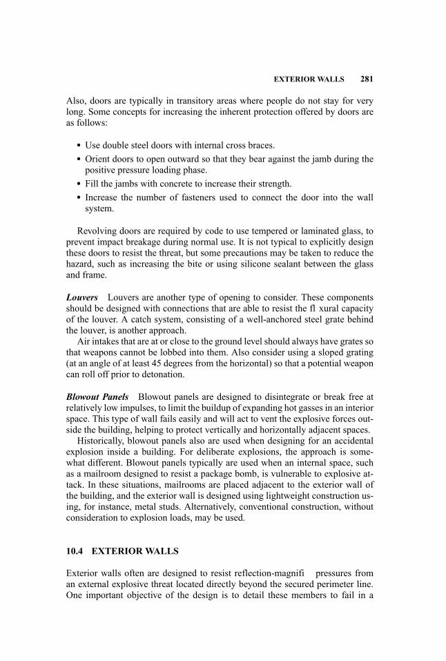
EXTERIORWALLS 281
Also, doors are typically in transitory areas where people do not stay for verylong. Some concepts for increasing the inherent protection offered by doors areas follows:
� Use double steel doors with internal cross braces.� Orient doors to open outward so that they bear against the jamb during thepositive pressure loading phase.
� Fill the jambs with concrete to increase their strength.� Increase the number of fasteners used to connect the door into the wallsystem.
Revolving doors are required by code to use tempered or laminated glass, toprevent impact breakage during normal use. It is not typical to explicitly designthese doors to resist the threat, but some precautions may be taken to reduce thehazard, such as increasing the bite or using silicone sealant between the glassand frame.
Louvers Louvers are another type of opening to consider. These componentsshould be designed with connections that are able to resist the fl xural capacityof the louver. A catch system, consisting of a well-anchored steel grate behindthe louver, is another approach.
Air intakes that are at or close to the ground level should always have grates sothat weapons cannot be lobbed into them. Also consider using a sloped grating(at an angle of at least 45 degrees from the horizontal) so that a potential weaponcan roll off prior to detonation.
Blowout Panels Blowout panels are designed to disintegrate or break free atrelatively low impulses, to limit the buildup of expanding hot gasses in an interiorspace. This type of wall fails easily and will act to vent the explosive forces out-side the building, helping to protect vertically and horizontally adjacent spaces.
Historically, blowout panels also are used when designing for an accidentalexplosion inside a building. For deliberate explosions, the approach is some-what different. Blowout panels typically are used when an internal space, suchas a mailroom designed to resist a package bomb, is vulnerable to explosive at-tack. In these situations, mailrooms are placed adjacent to the exterior wall ofthe building, and the exterior wall is designed using lightweight construction us-ing, for instance, metal studs. Alternatively, conventional construction, withoutconsideration to explosion loads, may be used.
10.4 EXTERIORWALLS
Exterior walls often are designed to resist reflection-magnifi pressures froman external explosive threat located directly beyond the secured perimeter line.One important objective of the design is to detail these members to fail in a

282 BUILDING ENVELOPE AND GLAZING
ductile mode such as fl xure, rather than a brittle mode such as shear. The wallsalso need to be able to resist the ultimate loads transmitted by the windows anddoors.
It may be cost-efficien to consider the reduction in pressure with height due tothe increase in distance and the angle of incidence at the upper levels of a high-rise building. Even if pressure reductions are taken into account at the upperfloors minimum requirements such as balanced design and ductile response areto be met, to reduce the hazard to occupants in case the actual explosion is greaterthan the design threat.
Various types of wall construction are considered below.
10.4.1 Concrete Walls
Cast-in-Place Historically, the preferred material for explosion-mitigatingconstruction is cast-in-place reinforced concrete. This is the material that is usedfor military bunkers, and the military has performed extensive research and test-ing on its performance. Reinforced concrete has a number of attributes that makeit an attractive construction material because of its mass, ductility, and monolithiccharacter.
Reinforced concrete is recommended for high-risk buildings that are vulnera-ble to large-scale attack, and require a high level of protection. It is also recom-mended for highly protected areas within buildings, such as primary egress pathsor high-occupancy areas.
Note that for reinforced concrete to respond favorably to explosion loads, it isto be detailed in a ductile manner, such as is done in high seismic zones. Someattributes of ductile protective design (Federal Emergency Management Agency2003) are as follows:
� Use symmetric reinforcement on both faces, so that load reversals may beaccommodated.
� Span the wall from floo to floo , rather than from column to column, toreduce the chances of building collapse.
� Stagger splices away from high-stress areas, to maintain the monolithiccharacter of the material.
� Space reinforcing bars no more than one wall thickness apart, but no lessthan one-half the wall thickness apart, to lessen the chances of localizedbrittle behavior.
� Use ductile special seismic detailing at plastic hinge locations, so that theyare able to develop the full moment of the span.
� Use full tensile development lengths to develop the ultimate fl xural capac-ity of the section.
� For progressive collapse prevention, consider the loss of an exterior wallthat measures vertically one floo height and laterally one bay width.

EXTERIORWALLS 283
� Use closed ties or spiral reinforcing along the entire length of beams andcolumns, including connections with a minimum bend angle of 135◦ and aspacing not exceeding d/2, to provide confinement
Precast Panels For precast panels, consider a minimum thickness of f veinches, exclusive of reveals, with two-way reinforcing bars to reduce the ultimateresistance, increase ductility, and reduce the chance of flyin concrete fragments.This will also reduce the reaction loads transmitted into the connections. In high-pressure regions, using ribbed panels (see Figure 10.7) may be an effective wayto resist the loads. These panels need to bear against the floo diaphragms.
The following are recommendations and considerations in designing precastelements for air-blast resistance.Reinforcement: Two symmetric, continuous layers of two-way reinforcement
are recommended to accommodate large deformations and rebound loads. Forthin panels where it is difficul to place two layers of reinforcement, the use oftwo layers of heavy wire mesh, one layer of two-way reinforcement along thecenterline, or staggered bars on either face may be considered.
If a single layer of reinforcement is used, it is critical to design the section sothat the steel yields before the concrete fails in compression to obtain a ductileresponse. Enhanced protection may be provided by placing fibe -reinforced poly-mers, geotextile materials, Kevlar, or similar materials on the inside face to pro-vide confinement resistance to scabbing and spalling, and added tensile capacity.If reinforcing bars are used, a layer of wire mesh on the interior face may help tofurther restrain concrete fragments from entering the space. Closely spaced barsalso help fragment restraint, but care must be taken not to increase the ultimate
Figure 10.8 Precast Concrete Ribbed Wall Panels
284 BUILDING ENVELOPE AND GLAZING
fl xural capacity too much, so as to keep the reaction loads to a reasonable level.Note that centerline reinforcement will not work in the rebound direction dueto the failure of the tension concrete during the positive phase. If the primaryobjective is to protect occupants and not passersby, then this may be acceptable.Above major egress points, however, where debris outside the building presentsan obstacle to ingress and egress post-event, added protection is desirable.Load-Bearing Systems: For progressive collapse resistance in load-bearing
precast systems, panels need to be designed to span over failed areas by meansof arching action, strengthened gravity connections, secondary support systems,or other means of providing an alternate load path.Connections: Ductile connections are recommended. The connections and
supporting structure need to be able to resist the loads transmitted by the panelloaded to its ultimate fl xural capacity, so that the system is balanced for the pos-sibility that the actual air-blast loading is higher than the design load. Reactionloads from the windows at ultimate capacity are to be included in the calculationof connection design loads. Using this approach, every panel with a differentconfiguratio will have a different set of design loads for the connections. Notethat small panels will have higher reaction loads than larger panels, using thismethod, due to their increased stiffness. Standardizing the panel sizes greatlysimplifie the connection load determination.
Also, the connections need to provide sufficien lateral restraint for the panelsto accept large deformations. Depending on the design details of the connectionused, lateral restraint design will require consideration of in-plane shear, buck-ling, fl xure, and/or tension loads in the design. Punching shear through the panelalso needs to be checked. The connection should provide a direct load path fromthe panel into the supporting structure to minimize P-Delta effects.
Floor-to-floo panels with continuous, gravity-type connections directly intothe floo diaphragms are preferred. Multistory panels that are hung on the floodiaphragms may also be considered. Connections into exterior columns or span-drel beams are discouraged, to avoid the possibility of initiating structural col-lapse of the exterior bay. Redundant gravity connections are strongly recom-mended, to prevent falling debris if a single connection fails.
Connections should be checked for rebound loads. It is conservative to usethe same load in rebound as for the inward pressure. More accurate values maybe obtained through dynamic analysis or charts provided in military handbooks(Unifie Facilities Criteria Program 2008).Specification : Specification for precast elements should be in the form of
a performance requirement, with the air-blast pressures and required responselimits. The performance specification give precast contractors more fl xibilityto provide the systems with which they are most familiar. This approach requiresthat the contractors have either in-house dynamic analysis capability or a rela-tionship with a blast engineer who can work with them to customize the mostcost-effective system.
For structural precast systems, the connections are the critical issue to beaddressed. Connections need to permit the panel to reach its ultimate fl xural

EXTERIORWALLS 285
capacity. Extensive use of transverse walls or an “egg crate” type of design isan effective way to achieve the needed lateral support. Special seismic detail-ing (American Concrete Institute 2008) is recommended for structural precastconnections.
Tilt-Up Construction Tilt-up construction is acceptable, provided that the con-nections into the structure are able to withstand the ultimate capacity of the wallin both the inward and outward (i.e., rebound) direction.
Post-Tensioned Panels Pre-tensioned or post-tensioned construction withoutsignifican mild steel reinforcement provides little capacity for abnormal loadingpatterns and load reversals. If these systems are used, it is recommended thatmild reinforcing be added, to provide the needed ductility
10.4.2 Masonry
Reinforced Masonry For concrete masonry unit (CMU) block walls, as a min-imum use 8-inch block walls, fully grouted with vertical centered reinforcingbars placed in each void, and horizontal ladder type reinforcement at each layer.Connections into the structure are to resist the reactions associated with the wallloaded to its ultimate lateral capacity. For infil walls, avoid transferring loadsinto the columns if they are primary load-carrying elements.
The connection details may be very difficul to construct. It will be difficul tohave all the blocks fi over the bars, near the top, and it will be difficul to providethe required lateral restraint at the top connection. A preferred system is to havea continuous exterior CMU wall that laterally bears against the floo system.For infil walls, use development lengths that develop the full capacity of thesection. For increased protection, consider using 12-inch blocks with two layersof vertical reinforcement. Also, consider using CMU block units that encouragea homogenous response, such as an “I”-shaped unit with inner and outer facesthat are connected with a small strut.
Unreinforced Masonry Brick load-bearing walls are unable to sustain tensileloads, so they must resist explosion loads mostly through mass to reduce thekinetic energy that must be absorbed. As a result, thicker solid walls on theorder of approximately 18 inches are preferred and respond well at air-blast lev-els less than 10 psi or so. Unreinforced structural masonry is considered a verybrittle material that may generate highly hazardous flyin debris in the event ofan explosion, and is to be avoided for new construction.
10.4.3 Steel
Metal Studs For metal stud systems, use metal studs back to back and mechani-cally attached. The two-stud system provides the benefi of lateral torsional resis-tance, and therefore can be more efficientl designed. To catch exterior cladding
286 BUILDING ENVELOPE AND GLAZING
fragments, attach a wire mesh, steel sheet, or fibe -reinforced polymer to the in-terior side of the panel. The supports of the wall should be designed to resist theultimate out-of-plane bending capacity load of the system.
If a single-stud system is used, deeper, thicker channels are preferred. As aminimum, consider 16-ga systems with depth of 6 inches, and laterally bracedare preferred.
Special care is required at the connections to prevent failure prior to the studreaching its ultimate capacity.
Enhanced protection may be provided by placing fibe -reinforced polymers,geotextile materials, Kevlar, or similar materials on the inside-face of thecladding to provide confinement fragment restraint, and added tensile capacity.
Metal Panels Non-structural metal panels may be successfully used if theyare braced behind with steel tubes or compact sections. Continuous welds arerequired around the perimeter braces to resist the membrane loads. At the endpanels, the braces will need to be augmented to account for the lack of equalizingforces.
10.4.4 Other
Appurtenances Brick veneers, bris soleil, sunshades, and other nonstructuralelements attached to the building exterior are to be avoided, to limit flyin debrisand improve emergency egress by ensuring that exits remain passable. If used,they should be designed using lightweight materials with connections designedto resist the ultimate capacity of the appurtenance.
Exposed Structural Systems For exposed exterior frame systems, there are twoprimary considerations. The firs is to design the exterior columns to resist thedirect effects of the specifie threats. The second is to detail the exterior frame sothat it has sufficien structural integrity to accept localized failure without initiat-ing progressive collapse. As a rule of thumb to meet these goals, column spacingshould be limited to 30 feet, and floo heights should be limited to not greaterthan 16 feet, wherever possible. It is recommended that the columns be designedto resist the explosive loads associated with a contact charge placed at the base,or that a column removal analysis be performed to verify that progressive col-lapse is not initiated.
Because columns do not have much surface area, air-blast loads on exposedstandalone columns that are not supporting adjacent wall systems tend to bemitigated by “clearing-time effects” (Unifie Facilities Criteria Program 2008).This refers to the fact that the pressure wave washes around these slender tallmembers, and consequently the entire duration of the pressure wave does not actupon them. Figure 10.9 shows an exposed column support on the corner of ahigh rise offic building.
For columns subject to a vehicle weapon threat close by in the public streetin an urban area, buckling and shear are the primary effects to be considered in

EXTERIORWALLS 287
Figure 10.9 Example of column freely exposed to public access. The column supportsthe corner of a high-rise building.
analysis. This is a common scenario considered for offic buildings in urban ar-eas. Because exposed columns are often in public areas and are primary supportmembers for buildings, the concern is that progressive collapse may be initiated.
A very large weapon close to a column can cause shattering of the concretedue to multiple tensile reflection within the concrete section, destroying its in-tegrity. Circular columns shed load more rapidly than rectangular columns andcan be beneficial
Buckling is a concern if lateral support may be lost when a floo system thatprovides lateral support is damaged. This is a situation that arises frequently foroffic buildings that are close to public streets. In this case, exterior columnsshould be capable of spanning two or more stories without buckling.
Insetting the firs line of columns a few feet into the building interior is anonconservative approach to protecting the columns. Even if the columns arenot publicly accessible, they are still vulnerable to air-blast effects, and theirresponse still needs to be addressed.
Protect columns by using closely spaced closed ties or spiral reinforcing, toimprove confinemen and shear capacity. This also will improve the performanceof lap splices in the event of loss of concrete cover, and greatly enhance columnductility. The potential cost-to-benefi ratio for providing closely spaced closedties in exterior concrete columns is among the lowest and should be consideredseriously. Closed ties are to be used in columns and spandrels for the entire spanand across connections with a maximum spacing of d/2 and a minimum bendangle of 135◦. Some other recommendations for reinforced concrete are given inwall subsection 10.4.1.
For exposed steel columns, splices should be placed as far above grade levelas practical, and base plates should be recessed below the ground level.

288 BUILDING ENVELOPE AND GLAZING
For a contact or close-in package weapon, column breach is a major consid-eration. To mitigate this threat, some suggestions include:
� Do not use exposed columns that are fully or partially accessible from thebuilding exterior. Arcade columns should be avoided (see Figure 10.10).
� Use an architectural covering that is at least 6 inches from the structuralmember. This will make it considerably more difficul to place a weapondirectly against the structure. Because explosive pressures decay so rapidly,every inch of distance will help to protect the column.
� Use steel plates to surround the base of concrete columns where it is acces-sible. Plates need to extend several feet above the accessible location.
� Encase steel columns with concrete and add a plate, 3/8′′–1/2′′ thick aroundthe perimeter for about 5 feet above the base, if necessary.
Load-bearing ductile reinforced concrete wall construction without columnscan provide a considerable level of protection if adequate reinforcement is pro-vided to achieve ductile behavior. This may be an appropriate solution for theparts of the building that are closest to the secured perimeter line (at scaled rangesless than 3).
Spandrel beams of limited depth generally do well when subject to air blast.In general, edge beams are very strongly encouraged at the perimeter of concreteslab construction, to afford frame action for redistribution of vertical loads andto enhance the shear connection of floor to columns. Confinemen of concretespandrels using closely spaced closed ties, such as those used for columns, isrecommended. Transfer trusses and transfer girders are to be avoided becausethey increase susceptibility to progressive collapse.
Figure 10.10 Example of public walkway beneath second floo of high-rise building
ROOF SYSTEMS 289
10.5 ROOF SYSTEMS
The primary loading on the roof is the downward air-blast pressure. The exte-rior bay roof system on the side(s) facing an exterior threat is the most critical.Roof systems that are low and therefore closer to the explosion will be subject tohigher pressures than high roof systems. The air-blast pressures on the interiorbays are less intense and may require less hardening. Secondary loads includeupward pressure due to the air blast penetrating through openings, and upwardsuction during the negative loading phase. The upward internal pressures mayhave an increased duration due to multiple reflection of the internal air-blastwave. It is conservative and recommended to consider the downward and up-ward loads separately.
Because roof systems are not exposed to the reflecte wave from the groundlevel, they are subject to lower pressures than the walls facing the explosion.Because the angle between a sloped roof and the advancing shock sometimesis less acute than the angle between a fla roof and the advancing shock front,sloping roofs may be subject to somewhat higher pressures. They are usually oflighter construction than fla roof systems, making them particularly vulnerableto air-blast effects unless designed to respond in a ductile manner. For this reason,sloped systems sometimes require more robust designs.
10.5.1 Concrete
The preferred system is to use cast-in-place ductile reinforced concrete withbeams in two directions. If this system is used, beams should have continuous,symmetrical top and bottom reinforcement with tension lap splices. Shear tiesshould develop the bending capacity of the beams and be closely placed alongthe entire span. All ties are to have a 135-degree bend minimum. Two-way slabsare preferred.
Precast and pre/post-tensioned systems, including hollow plank, are generallyviewed as less desirable due to the lack of ductility. If they are used, a systemthat has continuous bond with the concrete is preferred, with anchors that aredesigned to be protected from direct air-blast effects. Also, additional mild re-inforcement at top and bottom is recommended to ensure a ductile response.Connections need to be designed to resist both the direct and uplift forces.
Concrete fla slab/plate systems are also less desirable because of the potentialof punching shear failure at the columns. Where fla slab/plate systems are em-ployed, they should include features to enhance their punching shear resistance.Continuous bottom reinforcement should be provided through columns in twodirections, to retain the slab in the event that punching shear failure occurs. Edgebeams should be provided at the building exterior.
10.5.2 Steel
Lightweight systems, such as untopped steel deck, are considered to afford neg-ligible resistance to air blast. These systems are prone to failure due to their lowcapacity for downward and uplift pressure.
290 BUILDING ENVELOPE AND GLAZING
10.5.3 Composite
Modest levels of protection are afforded by conventional steel beam construc-tion with a steel deck and concrete fil slab. The performance of this system canbe enhanced by using normal-weight concrete fill increasing the gauge of deckand welded wire fabric reinforcement from that required for conventional loads,and making the connection between the slab and beams using additional shearconnector studs. Tension membrane behavior along the edges should be consid-ered in the design of the connections by using welding or fasteners along theedges. Since it is anticipated that the slab capacity will exceed that of the sup-porting beams, beam end connections and supporting columns should be capableof developing the ultimate fl xural capacity of the beams, to avoid brittle failure.Beam to column connections should be capable of resisting upward as well asdownward forces.
10.5.4 Penthouses/Gardens
Parapets, roof mechanical room enclosures, and tile roof systems are generallynot a primary concern, since they are exterior to the building. Generally thesemembers are designed to sustain heavy damage but not become flyin debris.Although roofin aggregate may become a flyin hazard, in the context of anexplosion event, this hazard is not significan enough to warrant much concern.
Soil can be highly effective in reducing the impact of a major explosive attack.Bermed walls and buried rooftops have been found to be highly effective for mil-itary applications and can be effectively extended to conventional construction.This type of solution can also be effective in improving the energy efficien y ofthe building.
10.6 BELOW GRADE
For buildings that are very close to the secured perimeter, there is the possibilityof the foundations becoming undermined by the cratering effects of an explosion.However, if this is an issue, then generally, it will be accompanied by heavy dam-ages to the superstructure as well. If the crater is projected to reach the building,then the most cost-effective option may be to increase the building setback.
Ground shock effects are generally a secondary effect since most of the energyof a vehicle weapon is transmitted to the air rather than the soil. The weaponwould have to be placed underground to have a significan effect on the structure.Currently, underground weapons are not considered by the governing federalcriteria for civilian buildings.
There are significan benefit to placing secured areas below grade in terms ofmitigating explosion effects from an exterior weapon. The massiveness and soft-ness of the soil provide a protective layer that significantl reduces the impulseon the structural systems below grade.

BELOW GRADE 291
For buildings with below-grade portions that are adjacent to the building,when creating a plaza level at ground level, keep in mind that the roof systems ofthese underground areas will need to be designed for the actual air-blast pressurelevels, if these are occupied areas. If these are unsecured areas, such as a garage,consider letting the roof fail if adequate egress routes are available on other sidesof the building, away from the failed plaza level.
Another consideration for belowground portions of the building is the designof the perimeter security barriers. The perimeter barriers often require deep foun-dations, which may interfere with the underground structure.
It is preferable to place underground garages adjacent to the main structurerather than directly underneath the building, to protect the structure against theeffects of an internal weapon. The effects of an internal weapon are generallynot a major concern for foundation walls. The soil on the other side of the wallprovides a buffer that mitigates the response. One exception to this is a situationwhere the foundation is below the water table, where even a localized breach ofthe wall may cause extensive collateral damage.
Vaults for transformers placed beneath the ground close to public streets areof concern. If possible, place these away from public streets. If they are in adriveway, the vault lid needs to be designed to resist the downward pressure.
In high seismic regions, seismic isolators may be used at the base of a building(Figure 10.11) . In this case, the response of the building globally should bechecked for the total air-blast loading acting on the side facing the explosion.Preliminary studies investigating this issue have shown that seismic responsegoverns.
moat
moat cover
retaining wall
flexible utility connection
base isolator
ground floor
basement
ground level
Figure 10.11 Diagram of seismic base isolation system. The building superstructure isdetached from the foundation and supported by steel plat/rubber bearings.

292 BUILDING ENVELOPE AND GLAZING
10.7 REDUCTION OF BLAST PRESSURES
The placement of the building on the site can have a major impact on its vulner-ability. Ideally, the building is placed as far from the property lines as possible.This applies not only to the sides that are adjacent to streets, but to the sides thatare adjacent to adjoining properties as well, since we cannot be certain abouthow access will change for those neighboring properties during the life of thebuilding. A common-practice example of this is the use of a large plaza area infront of the building, which often leaves little setback on the sides and rear of thebuilding. This practice can diminish the vulnerability of the front of the building,but generally will increase the vulnerability of the other three sides.
The shape of the building can have a contributing effect on the overall damageto the exterior envelope. Reentrant corners and overhangs are likely to causemultiple reflection of the air blast, which may amplify the effect of the air blast(see Figure 10.12).
(a)
(b)
Figure 10.12 Reentrant corner plans: (a) Some plan types. (b) T-shaped building withtwo reentrant corners.
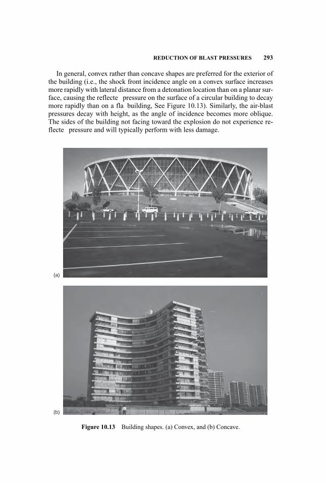
REDUCTION OF BLAST PRESSURES 293
In general, convex rather than concave shapes are preferred for the exterior ofthe building (i.e., the shock front incidence angle on a convex surface increasesmore rapidly with lateral distance from a detonation location than on a planar sur-face, causing the reflecte pressure on the surface of a circular building to decaymore rapidly than on a fla building, See Figure 10.13). Similarly, the air-blastpressures decay with height, as the angle of incidence becomes more oblique.The sides of the building not facing toward the explosion do not experience re-flecte pressure and will typically perform with less damage.
(a)
(b)
Figure 10.13 Building shapes. (a) Convex, and (b) Concave.

294 BUILDING ENVELOPE AND GLAZING
Generally, simple geometries, with minimal ornamentation (which may be-come flyin debris during an explosion), are recommended unless advancedstructural analysis techniques are used. If ornamentation is used, it is recom-mended that it consist of a lightweight material, such as timber or plastic, whichis less likely than brick, stone, or metal to become lethal projectiles.
REFERENCES
American Concrete Institute. 2008. Building Code Requirements for Structural Concreteand Commentary (ACI 318-08), Chapter 21. Farmington Hills, MI: American ConcreteInstitute.
Amstock, Joseph S. 1997. Handbook of Glass in Construction. New York: McGraw-Hill.ASTM. 2001. Standard Test Method for Structural Performance of Glass in ExteriorWindows, Curtain Walls, and Doors Under the Influenc of Uniform Static Loads byDestructive Methods (E997-01). West Conshohocken, PA: ASTM International.
. 2003. Standard Practice for Specifying an Equivalent 3-Second Duration De-sign Load for Blast Resistant Glazing Fabricated with Laminated Glass (F2248-03).West Conshohocken, PA: ASTM International.
. 2004a. Standard Practices for Determining Load Resistance of Glass in Build-ings (E1300-04e1). West Conshohocken, PA: ASTM International.
. 2004b. Standard Test Method for Glazing and Glazing Systems Subject toAirblast Loads (F1642-04). West Conshohocken, PA: ASTM International.
Computers and Structures, Inc. 1990. SAP2000/NonLinear User’s Manual. Berkeley,CA: Computers and Structures Inc.
Crawford, John, Shengrui Lan and Brian W. Dunn. 2006. Cable catcher systems for im-proving blast resistance of glazing facades. In Proceedings of the 19th Military As-pects of Blast and Shock Symposium, Alberta, Canada, October 2006. Burbank, CA:Karagozian & Case.
Federal EmergencyManagement Agency. 2003. Primer for Design of Commercial Build-ings to Mitigate Terrorist Attacks (FEMA 427). Washington, DC: Risk ManagementSeries of Publications, FEMA, Department of Homeland Security.
Hyde, David W. 1988.Microcomputer Programs CONWEP and FUNPRO, Applicationsof TM 5-855-1, Fundamentals of Protective Design for Conventional Weapons (User’sGuide). Vicksburg, MS: Army Engineer Waterways Experiment Station, StructuresLab.
Livermore Software Technology Corporation. 1999. LS-DYNA User’s Manual, Nonlin-ear Dynamic Analysis of Structures, Version 950. Livermore, CA: Livermore SoftwareTechnology Corporation.
MathSoft. 2001.Mathcad User’s Guide. Cambridge, MA: MathSoft Inc.MathWorks. 2006. MATLAB: The Language of Technical Computing, Version 7. Natick,MA: The MathWorks, Inc.
Unifie Facilities Criteria Program. 2007. DoD Minimum Antiterrorism Force ProtectionStandards (UFC 4-010-01) Washington, DC: U.S. Department of Defense, UnifieFacilities Criteria Program.

REDUCTION OF BLAST PRESSURES 295
. 2008. Structures to Resist the Effects of Accidental Explosions (UFC 3-340-02). Washington, DC: U.S. Department of Defense, Unifie Facilities Criteria Program.
U.S. Army Engineer Research and Development Center (ERDC). 2001. Window Frag-ment Hazard Level Analysis, the HAZL Model. Vicksburg, MS: U.S. Army EngineerResearch and Development Center.
11 Protection of Spaces
MeeLing Moy and Andrew Hart
Security can be integrated at the earliest stage of planning and continued through-out the design and construction phases for building structures requiring blast re-sistance, or other specialized security measures. Building occupant emergencyplans may also be included in planning such that the design created can supple-ment the objectives of emergency operations. The goal is to increase the chancesthat emergency systems will remain operational during an explosion. The con-tinued operation of particular building elements during emergencies is essentialfor building occupant life safety and evacuation. This chapter will focus on thefollowing building components: areas isolating interior threats, stairwell enclo-sures, hardened plenums, and safe havens.
11.1 AREAS ISOLATING INTERIOR THREATS
Interior explosive threats may be carried or delivered into accessible areas withina building. These areas include, but are not limited to, loading docks, mailrooms,and lobbies. The magnitude of interior threats and the specifi areas isolatingthem within a building are identifie by a risk assessment. The Federal Emer-gency Management Agency (FEMA) define a small explosive to be approxi-mately 5 to 10 pounds of TNT equivalent, a large explosive to be approximately50 to 100 pounds of TNT equivalent, and a mail bomb to usually be less than 10pounds of TNT equivalent.
Protection of critical building components and systems within the identifieinterior high-risk areas may be achieved by installing electronic surveillancecameras, by implementing controlled access with entry and/or exit checkpointscreening, and by structural hardening.
Walls and slabs enclosing specifi interior high-risk areas should be designedor hardened for the identifie interior threats as determined by a risk assessment.FEMA recommends that blast effects should be vented through the walls iso-lating interior threats. For example, these walls may consist of blowout panelsdesigned to provide security from blast loads applied on the outside due to anexterior threat, but to fail due to an interior threat, thus venting the blast loads
297
Handbook for Blast-Resistant Design of Buildings Edited by Donald 0. Dusenberry
Copyright 0 2010 by John Wiley & Sons, Inc. All rights reserved.
298 PROTECTION OF SPACES
outside. FEMA suggests that slabs isolating interior threats should be designedor hardened to consider downward and upward blast loads.
11.2 STAIRWELL ENCLOSURES
Exit and emergency egress stairwells are considered to be spaces that are acces-sible to the general public. They are designed for optimal performance with suf-ficien distribution and redundancy to meet current building code requirements,and building occupant needs. Stairwell planning and design are a fundamentalpart of a building occupant emergency plan. FEMA recommends that stairwellsshould maintain positive pressure for safe evacuation of building occupants, andfor access by firefighte and rescue responders during an emergency. The instal-lation of special filterin systems to provide a clean source of air may be required,to maintain positive pressure and minimize smoke and hazardous gases in stair-wells. The National Institute of Standards and Technology (NIST) recommendsthat stairwell design capacities should also take into account the counterfl w ofrescue personnel during an emergency. Stairwell lighting should remain func-tional during an emergency, and stairwell exit signs should provide a clear andcontinuous route to the outside or to another area that is safe. In addition to thebuilding code requirements, stairwells should be located in less vulnerable areas,and far from areas where blast events may occur in the building. Thus, stairwellsshould not discharge into high-risk areas.
Exit and emergency egress stairwell enclosures, which include walls andslabs, should be designed or hardened for the identifie threats specifie in arisk assessment. FEMA recommends that stairwell walls should be anchored tothe floo slabs at each end, in order to adequately transfer the loads from a blastto the lateral resisting structural system of the building. FEMA suggests thatstairwell slabs should take into account the uplift pressures from a blast by us-ing an upward load equal to the dead load plus half the live load for the floosystem. FEMA also recommends that doors to the stairwell enclosures shouldconsist of steel, and be adequately anchored to the stairwell walls. FEMA alsosuggests that windows in the stairwell enclosures consist of laminated glass witha 60-mil polyvinyl butyral (PVB) interlayer. The laminated glass should be ad-hered within the window frames and mullions using a 1/2-inch bead of structuralsilicone. The window frames and mullions should be anchored to the stairwellwalls in order to develop the full capacity of the window glazing.
11.3 HARDENED PLENUMS
Mechanical equipment and systems are considered to be primary nonstructuralelements that are necessary for the life-safety procedures of a building. Theirconfiguration and capacities are designed with adequate redundancy to meetcurrent building code requirements and building occupant needs. They are
SAFE HAVENS 299
identifie as critical assets that should continue main operations during an emer-gency, to ensure the safe evacuation of building occupants. FEMA recommendsthat public access to critical mechanical equipment and systems should berestricted, in order to reduce the potential damage from a blast event. In additionto the building code requirements, primary and redundant mechanical equipmentand systems should be situated in separate locations and far from high-risk areas,to reduce the possible hazard of both being damaged by a single blast event.
Structural elements supporting the plenum that surrounds the mechanicalequipment should be designed or hardened to resist reflecte blast pressuresand impulses, such that debris and fragments are not propelled into the pro-tected spaces. Mechanical vents and exposed plenums are designed or hardenedto the same level of protection as required for exterior walls. Designs should takeinto account the potential infil of blast overpressures through mechanical open-ings. Structural elements and mechanical equipment mountings and attachmentsshould be designed to resist these internal pressures.
11.4 SAFE HAVENS
A safe haven can be define as a secure area designed to protect occupants fromvarious hazards. Such shelters may be located outside or within a structure. Safehavens are fully enclosed structures designed to resist the effects of blast loads,and the impact of fragments and debris due to an explosive event. This sectionwill focus on safe havens as documented by FEMA.
11.4.1 FEMA Documents
The FEMA document that deals with the protection of safe havens is primar-ily FEMA 453, Safe Rooms and Shelters, Protecting People Against TerroristAttacks, dated May 2006. Within the document two types of shelters are defined
� Standalone shelter� Internal shelter
The difference between the two types of shelters is that a standalone shelteris a define as a building that is not attached to or within any other building; itis considered as a separate building. This separate building is to be constructedto withstand a range of natural or man-made hazards and may be situated awayfrom any debris or potential fragment hazards. The building is to be structurallyseparated from any other building, and thus not be affected by any weakeningfrom an adjacent building collapsing. Since this is a separate building, it doesnot need to be integrated into the building design, but it is costly compared withan internal shelter.
An internal shelter is a specially designed room within or attached to a build-ing. The room is designed to be structurally independent of the building and is
300 PROTECTION OF SPACES
able to withstand a range of natural or man-made hazards. Since the shelter ispartially shielded by the building, it may not get the full blast pressure. The lo-cation of the room within the building has to be easily accessible by all buildingoccupants, and when designing for blast mitigation, no resistance from any ofthe surrounding areas should be included. Having it within the building is lesscostly than building a standalone shelter, as it can be part of a renovation or alater addition to the building design.
11.4.2 Multi-Hazard Threats
FEMA 453 does not quantify a specifi threat such as a terrorist threat from avehicle bomb; rather, the document gives general guidelines on different types ofbuilding construction and reasonable mitigating measures for providing a secureshelter.
Prior Warning In some instances, prior to an event, a warning is given. Alltypes of warnings given about any type of threat should be treated in a simi-lar manner. The standard procedure for a prior warning is laid out in FEMA453: Once the warning has been received, the contacted person calmly asks forthe location of the weapon (e.g., the building where it is housed), the type ofweapon, and any other pertinent information that he or she can obtain. Onceobtained, the contacted person must immediately call his/her local enforcementagencies—such as local and federal law agencies—and emergency services, andpass on all information from the perpetrator. All warnings should be treated asreliable, regardless of their apparent validity.
Sequential Events after/during an Event Every type of shelter, regardless ofits size and number of occupants, should have an Emergency Operations Center,or EOC. This center or group of people serves as an information managementcenter where decisions are made, such as those made during the attacks on thetwin towers on September 11, 2001. Each EOC should be equipped with com-munication equipment, reference materials such as medical books, log books tonote down what happened and when, and any other tools necessary to respondquickly and appropriately to an emergency, such as a defibrillato and a firs aidkit. Within this center, the Emergency Management Group (EMG) makes deci-sions based upon the information provided by the Incident Commander (IC) andother personnel. The relationship between the EMG and the emergency servicesor Emergency Operations Group (EOG) is shown in Figure 11.1. Note that boththe EMG and the EOG have directors, each in constant contact with each otherthroughout the duration of the event, coordinating the responses to the event as itunfolds.
The use of an IC is vital, as this person is responsible for the front-linemanagement of the response to the incident, tactical planning and execution,determining if help is required, and relaying requests for assistance, if required,
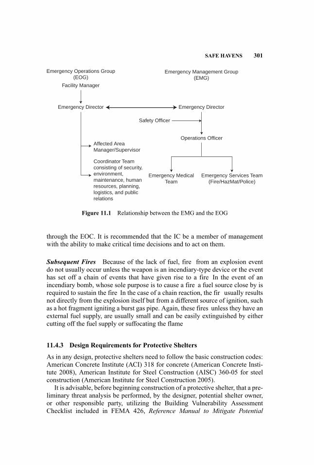
SAFE HAVENS 301
Emergency Operations Group(EOG)
Emergency Management Group(EMG)
Facility Manager
Emergency Director Emergency Director
Safety Officer
Operations Officer
Emergency Services Team(Fire/HazMat/Police)
Emergency MedicalTeam
Affected AreaManager/Supervisor
Coordinator Teamconsisting of security,environment,maintenance, humanresources, planning,logistics, and publicrelations
Figure 11.1 Relationship between the EMG and the EOG
through the EOC. It is recommended that the IC be a member of managementwith the ability to make critical time decisions and to act on them.
Subsequent Fires Because of the lack of fuel, fire from an explosion eventdo not usually occur unless the weapon is an incendiary-type device or the eventhas set off a chain of events that have given rise to a fire In the event of anincendiary bomb, whose sole purpose is to cause a fire a fuel source close by isrequired to sustain the fire In the case of a chain reaction, the fir usually resultsnot directly from the explosion itself but from a different source of ignition, suchas a hot fragment igniting a burst gas pipe. Again, these fires unless they have anexternal fuel supply, are usually small and can be easily extinguished by eithercutting off the fuel supply or suffocating the flame
11.4.3 Design Requirements for Protective Shelters
As in any design, protective shelters need to follow the basic construction codes:American Concrete Institute (ACI) 318 for concrete (American Concrete Insti-tute 2008), American Institute for Steel Construction (AISC) 360-05 for steelconstruction (American Institute for Steel Construction 2005).
It is advisable, before beginning construction of a protective shelter, that a pre-liminary threat analysis be performed, by the designer, potential shelter owner,or other responsible party, utilizing the Building Vulnerability AssessmentChecklist included in FEMA 426, Reference Manual to Mitigate Potential
302 PROTECTION OF SPACES
Terrorist Attacks Against Buildings (Federal Emergency Management Agency2003).
When the preliminary threat analysis has been performed, an independent de-sign professional should perform a more thorough assessment of the shelter toeither confir the preliminary assessment or modify it accordingly if any deficiencies are found within the design/assessment.
If an existing building is to be used as a shelter, an assessment utilizing theFEMA 426 Checklist will help to determine the building vulnerabilities and thusaid in its modifications It should be noted that FEMA 426 provides guidance tothe building construction industry in how to reduce physical damage to buildings.The purpose of the manual is to show various approaches that can be taken tominimize the effects of terrorist threats.
Resistance to Progressive Collapse Progressive collapse occurs when a lo-calized failure occurs and the adjoining members are overloaded. This causesfailure of the members, and a cascade or “pancaking” failure effect occurs. Thisfailure may result in a partial or total failure of the structure. The initial local-ized failure could be the result of a small parcel bomb in direct contact with acritical structural element, or the source could be a vehicle-borne explosive de-vice located a relatively short distance away. A larger explosive device located alonger distance away is not likely to cause a single member to fail, but will prob-ably affect a number of structural elements instead, which is not deemed failureby progressive collapse. In addition, according to FEMA 453, Safe Rooms AndShelters: Protecting People Against Terrorist Attacks (Federal Emergency Man-agement Agency 2006), progressive collapse is not an issue for buildings withthree stories or fewer.
The use of transfer girders and nonductile, nonredundant construction is pro-hibited in the building construction, as it may give rise to structural systemsthat are not tolerant of localized damage. The columns that support transfergirders—and the transfer girders themselves—may be critical to the stability ofa large floo area. For interior shelters, the building surrounding the shelter mustbe sufficientl hardened so that progressive collapse is not an issue. For thesebuildings, it is required that the structural integrity of the building must still beintact if a member fails.
Some of the characteristics that a building containing a shelter must have toresist progressive collapse are:
� Mass: The larger the inertial resistance, the more resilient it is to failure.� Shear Capacity: Connections and members need to be designed to preventfailure.
� Capacity for Load Reversals: Some members may undergo several largedeformations before damping down. These load reversals can be in the formof uplift pressures, which defy the normal convention of gravity load design.Structural elements subject to blast effects, therefore, should be designedfor load reversal. For design purposes, it is usualto provide equal areas of
SAFE HAVENS 303
reinforcing steel on both sides of reinforced concrete members, to providethe necessary resistance. The connections also need to be designed for loadreversals.
� Redundancy: The use of an alternative load path in the vertical load-carryingsystem. This allows the gravitational loads to redistribute in the event of astructural member failure.
� Ties: The use of an integrated system of ties can serve to redistribute theloads. The ties need to be located perpendicular to the principal line ofstructural framing.
� Ductility: The ability of a structural member or connection to have a largedeformation while still maintaining strength. Allowing the member to in-elastically deform (e.g., plastically deform) causes large amounts of blastenergy to dissipate; however, special detailing is required.
Using the above guidelines for designing buildings with shelters, or shel-ters themselves, robustness is greatly improved and progressive collapse maybe avoided. For existing structures that are being modifie to accommodate ashelter, it may be possible to allow only one floo adjacent to the failed columnto fail, but if the structural members are retrofitte to develop catenary behavior,the adjoining bays must be upgraded to resist the lateral forces. This may resultin more extensive retrofittin than is feasible or desirable. When such cases oc-cur, isolate this region and risk the collapse of the adjoining bays by upgradingthe vulnerable localized columns. When upgrading these columns, a balanceddesign approach must be obtained. It should be noted that upgrading an existingbuilding for an alternative load path system is potentially counterproductive.
For buildings that can provide a continuous load path that will support allvertical and lateral loads, all structural components and fasteners used in theconnection system must be able to develop the full capacity of the member. Inorder for this to take place, the capacity of each component must be balancedwith the capacity of the other members and their connections. As all appliedloads must be transferred eventually to the foundation/ground, the load path mustbe continuous from the top structural member to the ground.
Location within the Building One of the most important factors when dealingwith a shelter is its location, including determining the best location for savinglives. The location of the shelter will depend on how many occupants the shelterhas to hold. In addition to the effects of blast, the location should also considereffects of chemical, biological, and radiological threats. The shelter should belocated such that all persons who are to take refuge can reach it within a minimaltravel time from where they are located. A way to ease travel time is to clearlymark the route to the shelter.
Standalone shelters should be located as far as deemed possible from the sur-rounding buildings, to avoid both progressive collapse and/or impacts from thecollapse of nearby buildings. Internal shelters require that the main building bedesigned for progressive collapse.
304 PROTECTION OF SPACES
Access to Egress Shelter locations should be such that all designated per-sons may take refuge within the shelter with a minimum of travel time. Travelroutes to the shelter should be clearly marked, allowing easy access. Exit routesfrom the shelter should direct the persons away from the threat, and hazardssigns should be located using Crime Prevention through Environmental Design(CPTED) principles. These principles make use of natural access control, naturalsurveillance, and territoriality, which can also help to deter the aggressor.
Access to the building must be as “natural” as possible, in that the siting ofthe entrances, exits, fences, lighting, and landscaping tends to guide people whoare entering or exiting the building. This is called “natural access control,” andwhen it is coupled with limited access, the opportunity for a terrorist attack isgreatly reduced. The placement of external features such as bushes, trees, andfountains must also be considered so that visibility is maximized. This is termed“natural surveillance,” and it can reduce the opportunity for terrorists to attack,by revealing their intentions; in addition, it gives a feeling of safety, as the publiccan be easily seen. Finally, the use of fences, bollards, signage, and the like,termed “territoriality,” clearly define the property lines between what is publicand private. This can be a gateway into a community or neighborhood.
Fire Rating There are only two fir ratings, H and A (Steel Construction Insti-tute 1990). The H fir rating is solely for hydrocarbon fire such as those causedby a petroleum product. The A rating is for normal fire such as those that havewood or paper as their source of fuel. A number usually follows the letter, suchas 60 or 120, and the value represents the time that structural integrity can bemaintained during a fire—e.g. how long a member or area can be kept below adesignated temperature, usually 40◦C, before the temperature rises, causing thatmember to plasticize and fail. In H-rated fires the maximum temperature is des-ignated as 1100◦C within 10 minutes, and for A, the maximum temperature is950◦C, over 60 minutes (Steel Construction Institute 1990). See Figure 11.2. Itis usual for commercial buildings to be designated as A-rated, as the chances ofa hydrocarbon fir within one of these buildings is remote.
Currently, the fir protection of buildings, based on FEMA, is based on afour-level hierarchy that comprises alarm and detection, suppression, compart-mentation, and passive protection.
� Fire alarms and detectors are usually used to activate the system and notifythe building occupants and emergency services through verbal and visiblesystems.
� Suppression systems, usually in the form of water sprinkler systems, areprimarily designed to control small to medium fire and to prevent the firspreading beyond the water zone, which is typically 1,500 square feet.
� Use of compartmentation will mitigate the spread of more severe firesThese typically require fire-rate partitions between the rooms and cancover an area of 12,000 square feet.
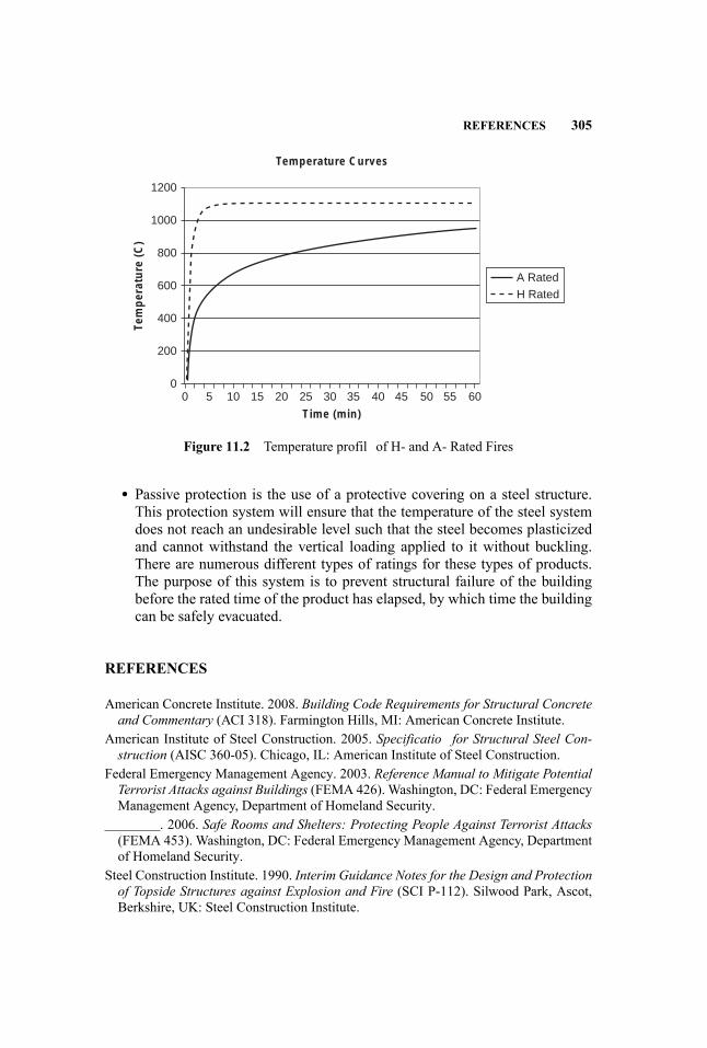
REFERENCES 305
1200
1000
800
600
Tem
per
atu
re (
C)
Time (min)
Temperature Curves
400
200
00 5 10 15 20 25 30 35 40 45 50 55 60
A Rated
H Rated
Figure 11.2 Temperature profil of H- and A- Rated Fires
� Passive protection is the use of a protective covering on a steel structure.This protection system will ensure that the temperature of the steel systemdoes not reach an undesirable level such that the steel becomes plasticizedand cannot withstand the vertical loading applied to it without buckling.There are numerous different types of ratings for these types of products.The purpose of this system is to prevent structural failure of the buildingbefore the rated time of the product has elapsed, by which time the buildingcan be safely evacuated.
REFERENCES
American Concrete Institute. 2008. Building Code Requirements for Structural Concreteand Commentary (ACI 318). Farmington Hills, MI: American Concrete Institute.
American Institute of Steel Construction. 2005. Specificatio for Structural Steel Con-struction (AISC 360-05). Chicago, IL: American Institute of Steel Construction.
Federal Emergency Management Agency. 2003. Reference Manual to Mitigate PotentialTerrorist Attacks against Buildings (FEMA 426). Washington, DC: Federal EmergencyManagement Agency, Department of Homeland Security.
. 2006. Safe Rooms and Shelters: Protecting People Against Terrorist Attacks(FEMA 453). Washington, DC: Federal Emergency Management Agency, Departmentof Homeland Security.
Steel Construction Institute. 1990. Interim Guidance Notes for the Design and Protectionof Topside Structures against Explosion and Fire (SCI P-112). Silwood Park, Ascot,Berkshire, UK: Steel Construction Institute.
12 Defended Perimeter
Joseph L. Smith and Charles C. Ellison
The four main functions of any comprehensive physical security program areto deter, detect, delay, and respond to a threat. A defended perimeter servesan important role in achieving these aims. A well-planned perimeter can deteran aggressor by increasing the perceived difficult of attack, can support theimplementation and function of detection sensors, and can delay an aggressor,providing the security force time to respond to an attack.
12.1 GOALS
The perimeter barrier system will generally be the outermost zone in a tieredsystem of protections that includes the building facade and internal screeningzones such as visitor lobbies, mailrooms, and loading docks. These zones, asshown in Figure 12.1, can be viewed as concentric layers of protection.
In terms of the primary topic of this book, the goal for each tier should be toreduce the size of the likely explosive threat to a level that can be mitigated byreasonable levels of blast hardening. As the firs line of defense, the perimeter isthe foundation on which all other blast-mitigation options are selected. As such,the defended perimeter must address the largest threats to the facility. Failureof the perimeter to perform as expected can have severe consequences for theadequacy of subsequent blast-mitigation methods.
Heavy barriers are not the only option when creating a defended perimeter.Perimeter protection may include effective site planning and landscape designthat, if deployed properly, can substantially decrease the risk to occupants andmitigate damage to a facility. The effective use of landscaping and terrain canalso minimize the design requirements and cost of other man-made barriers em-ployed to stop vehicles or other threats.
12.2 STANDOFF
The standoff distance is generally considered to be the range between the centerof the explosive device and the nearest structural element requiring protection
307
Handbook for Blast-Resistant Design of Buildings Edited by Donald 0. Dusenberry
Copyright 0 2010 by John Wiley & Sons, Inc. All rights reserved.
308 DEFENDED PERIMETER
Figure 12.1 Zones of Protection
(i.e., the target). The term “setback” is used when discussing the distance be-tween a facility and the defended site perimeter. These terms are often used in-terchangeably; however, standoff and setback do not necessarily have to be equal.
Since blast loads decay rapidly with distance, setback can be an effectivemeans of protecting a facility from an explosive attack. The firs few feet providethe most benefit Figure 12.2 illustrates peak pressure versus standoff curves fora range of explosive devices [Based on Equations in UFC 3-340-02, Structures toResist the Effects of Accidental Explosions (Unifie Facilities Criteria Program2005b)].
As shown in Figure 12.2, at very small standoff distances (i.e., less than 5 ft)just an extra foot of additional standoff can reduce the blast load on a structuralmember by an order of magnitude (i.e., a factor of 10) or more. It may only takea few pounds of explosive in direct contact with a structural column or wall tocause devastating structural collapse. However, that same column or wall mayresist several hundred pounds of explosives if only a few feet of standoff areprovided. The benefit of a few additional feet of standoff can also be significanat much greater distances. For example, the pressure loads generated by a 500-lbTNT bomb at 112 ft are over 20% less than the loads generated at 100 ft.
Even though the benefi per foot of standoff decreases with distance, provid-ing standoff is often more cost-effective than structural hardening for significandistances from the facility. To illustrate this point, the approximate relationship
STANDOFF 309
10,000
1,000
100
5 lb TNT50 lb TNT500 lb TNT5,000 lb TNT50,000 lb TNT
10
1
0.50 100 200 300 400 500
Standoff (ft)
Pre
ssu
re (
psi
)
600 700 800 900 1,000
Figure 12.2 Blast Pressure Loading versus Standoff
between defended standoff and protection offered by conventional constructionis shown in Figure 12.3 (Smith et al. 2005).
Figure 12.3 illustrates the level of protection offered by a wide range of con-ventionally constructed buildings for a given setback. The left portions of thebars indicate that no significan protection from blast effects is readily attainableat these distances with conventional construction. The next area is an indica-tion of a low level of protection. At these distances, conventionally constructedbuildings will typically sustain moderate to heavy damage. Occupants in ex-posed structures may suffer temporary hearing loss and injury from the forceof the blast wave and building debris fragmentation. Other assets may receivedamage from these effects. The third area is an indication of a medium levelof protection. At these distances, conventionally constructed buildings will gen-erally sustain light to moderate damage. Occupants of exposed structures maysuffer minor injuries from secondary effects such as building debris. The right-most area indicates a high level of protection. At these distances, conventionallyconstructed buildings will generally sustain only minor damage.
12.2.1 Balancing Hardening with Standoff
A common question that designers face is “Where do I put my barriers?” Typ-ical security personnel will declare that barriers must be as far away from theprotected asset as possible. Typical architects will respond that barriers intrude
310 DEFENDED PERIMETER
No Protection
1000
500
220
50
0
Standoff Distance (Feet)
200 400 600
Exp
losi
ve W
eigh
t (lb
s.)
Medium-LevelProtection
High-LevelProtection
Low-LevelProtection
Figure 12.3 Effects of Standoff Distance for a Typical Conventionally ConstructedFacility (explosive weight is in lbs of TNT equivalent)
on the appearance and function of the project and must be minimized. Typicalowners will say they want to be safe but, at the same time, not inconvenienced.Typical community planning boards will want free, unrestrained access to thesite for community use. In most practical cases, especially for government facil-ities, there may be design criteria that prescribe a specifi minimum standoff forthe define threats. In other cases, there may be no such clear requirement. In theend, politics or other nontechnical factors may also play a deciding role in theselection and placement of barrier systems.
So what’s a designer to do? It is important to consider all aspects of thedesign in determining where barriers are placed, the type of barriers to be used,and the protection level that such barriers will provide. The site features mayplay a role in determining the placement of the protected asset or buildingwithin a protected site. From a protection engineer’s perspective, balancingsetback requirements with structural hardening and hazard-mitigating featuresshould be of primary concern. Designing to resist explosive effects increases the
STANDOFF 311
requirements of structural components; thicker walls, additional reinforcement,and blast-resistant glazing and frames may be needed. An increase in explosiveweight or a decrease in standoff generally increases structural requirements. Foran efficien design, one must balance the effect of available standoff with theeffect of incorporating blast-resistant design and/or hazard-mitigation measures.
The types of perimeter protection should also be balanced with the types ofattacks considered in the risk assessment. A crash-rated barrier line is not neededif the attackers are unwilling to risk drawing attention to themselves. However,heavy barriers may be the only option to stop a truly determined attacker. Poten-tial attacks can generally be reduced to three types:
� A true covert attack in which the attacker desires to completely escape no-tice and repercussion. Attackers of this type will avoid anything that drawsattention to themselves, such as high speeds and illegal parking. Eliminat-ing public parking near the building and presenting a notable guard presencewill deter this type of attacker and provide standoff.
� An attack in which the aggressor is dedicated to the attack, but intends toescape. This attacker will break traffi laws, but wants to get out of thearea before a police response can be mounted. Designated parking or evenillegal parking will not deter this attacker since he or she can fle the areabefore a response is mounted. However, heavy-rated barrier systems are notnecessarily required, since this type of attacker will be deterred by the riskof a potentially fatal crash or a significan delay in escaping.
� A suicide attack by an attacker who is willing to be captured or killed inthe attempt. If vehicle barriers are not in place, this attacker will drive ontothe site and through the front door of the building. Stopping this threat willrequire significan and consistent hardening of the perimeter against vehicu-lar attacks. Developing appropriate limits on achievable barrier penetrationis crucial. Sally ports and other redundant barriers may be necessary at allvehicular entrances.
12.2.2 Balancing Costs
The effects of standoff provided by barrier systems on various structural andnonstructural components are conceptually illustrated in Figure 12.4 (Smithet al. 2005). This figur generally illustrates, at no specifi scale, the typicalrelationships between standoff and the cost of protection. A number of thevarious components of incremental security cost are shown, including structuraland nonstructural component contributors. The relative magnitude and scale ofthese relationships will vary from project to project.
For example, the cost associated with hardening the mailroom, loading dock,and lobby to meet the design requirements may not vary with the available stand-off to a vehicle-delivered bomb along the site perimeter. The cost associated withprogressive collapse considerations may also be constant with standoff, since it
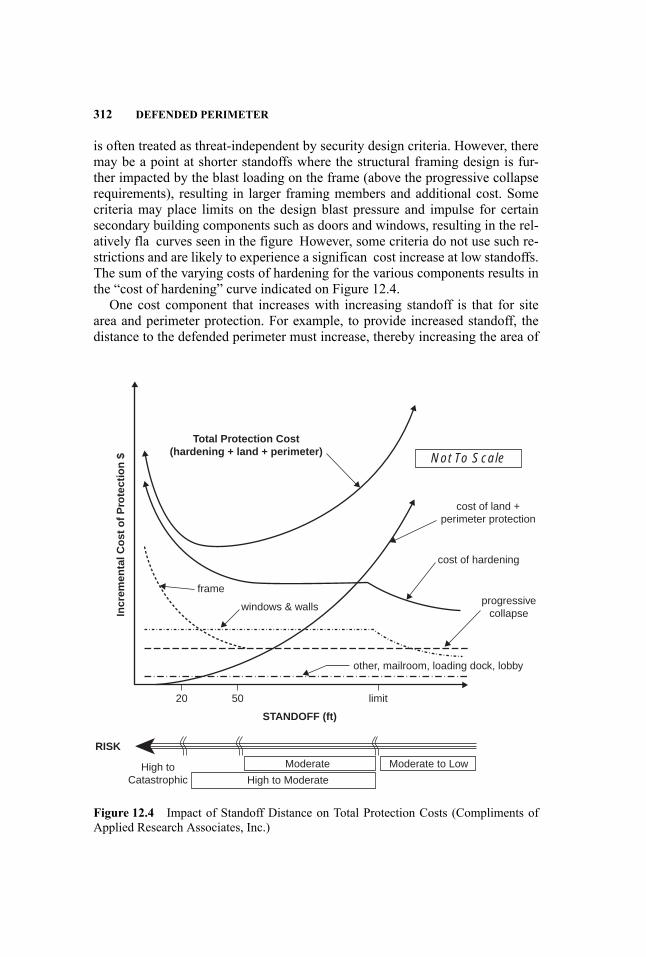
312 DEFENDED PERIMETER
is often treated as threat-independent by security design criteria. However, theremay be a point at shorter standoffs where the structural framing design is fur-ther impacted by the blast loading on the frame (above the progressive collapserequirements), resulting in larger framing members and additional cost. Somecriteria may place limits on the design blast pressure and impulse for certainsecondary building components such as doors and windows, resulting in the rel-atively fla curves seen in the figure However, some criteria do not use such re-strictions and are likely to experience a significan cost increase at low standoffs.The sum of the varying costs of hardening for the various components results inthe “cost of hardening” curve indicated on Figure 12.4.
One cost component that increases with increasing standoff is that for sitearea and perimeter protection. For example, to provide increased standoff, thedistance to the defended perimeter must increase, thereby increasing the area of
frame
cost of hardening
limit5020
High toCatastrophic
Moderate Moderate to Low
STANDOFF (ft)
Not To Scale
RISK
Incr
emen
tal C
ost
of
Pro
tect
ion
$
High to Moderate
other, mailroom, loading dock, lobby
progressivecollapse
windows & walls
cost of land +perimeter protection
Total Protection Cost(hardening + land + perimeter)
Figure 12.4 Impact of Standoff Distance on Total Protection Costs (Compliments ofApplied Research Associates, Inc.)
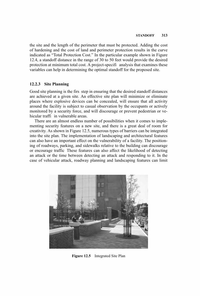
STANDOFF 313
the site and the length of the perimeter that must be protected. Adding the costof hardening and the cost of land and perimeter protection results in the curveindicated as “Total Protection Cost.” In the particular example shown in Figure12.4, a standoff distance in the range of 30 to 50 feet would provide the desiredprotection at minimum total cost. A project-specifi analysis that examines thesevariables can help in determining the optimal standoff for the proposed site.
12.2.3 Site Planning
Good site planning is the firs step in ensuring that the desired standoff distancesare achieved at a given site. An effective site plan will minimize or eliminateplaces where explosive devices can be concealed, will ensure that all activityaround the facility is subject to casual observation by the occupants or activelymonitored by a security force, and will discourage or prevent pedestrian or ve-hicular traffi in vulnerable areas.
There are an almost endless number of possibilities when it comes to imple-menting security features on a new site, and there is a great deal of room forcreativity. As shown in Figure 12.5, numerous types of barriers can be integratedinto the site plan. The implementation of landscaping and architectural featurescan also have an important effect on the vulnerability of a facility. The position-ing of roadways, parking, and sidewalks relative to the building can discourageor encourage traffic These features can also affect the likelihood of detectingan attack or the time between detecting an attack and responding to it. In thecase of vehicular attack, roadway planning and landscaping features can limit
Figure 12.5 Integrated Site Plan

314 DEFENDED PERIMETER
the impact speed and approach angle of an attacking vehicle, resulting in lighterbarrier requirements. However, it is important that security be considered earlyin the design process, when civil, architectural, and structural changes can bemade with minimal impact on ongoing designs in other nonsecurity disciplines.
Controlling the maximum impact velocity of an attacking vehicle is one veryimportant part of site planning, since the velocity term is squared in the rela-tionship for kinetic energy and has a very large effect on the size and cost ofvehicular barriers. For example, doubling the impact speed increases the impactenergy for a given vehicle impact by a factor of four, thus greatly increasing thedesign requirements and potential cost of a barrier system.
Using basic engineering and physics, there are formulas and methods avail-able to estimate the maximum attainable impact speeds that a vehicle may obtain.Performing such a study early in the planning process can significantl reducethe costs associated with vehicle barriers.
Attainable Vehicle Speed on a Straight, Level Path The most basic vehiclespeed calculation is based on a straight and level path between the starting pointand the vehicle barrier. The fina speed for such an approach can be calculatedusing the following basic equation (Unifie Facilities Criteria Program 2005b):
v2f = v20 + 2as
where: vf = fina vehicle velocityv0 = initial vehicle velocitya= constant rate of accelerations= distance traveled
Initial vehicle velocity and distance traveled are easy concepts to grasp anddevelop input values for. However, rate of acceleration can be difficul to deter-mine. First, acceleration is very dependent on the weight and power output ofthe vehicle. Average accelerations between zero and 60 mph can range from 25feet per second squared for a modern sports car to 5.8 ft per second squared for a2.5-ton commercial truck. Second, acceleration is not constant. Neglecting dragand rolling friction, a vehicle producing a constant 200 hp at the rear wheels andweighing 4000 lb will accelerate from 20 mph to 30 mph in 0.61 sec (averageacceleration = 24 ft/secˆ2). However, the same vehicle will require 1.34 secondsto accelerate from 50 mph to 60 mph (average acceleration = 11 ft/secˆ2). Ascan be seen, a 30-mph increase in speed reduced the rate of acceleration byone half.
These numbers were obtained by solving the following equations throughtime:
vi = v(i-1) + a(i-1)(dt)ai = P/(mvi )

STANDOFF 315
where: P= powerm=massvi = current velocity
v(i-1) = velocity at last time incrementai = current acceleration
a(i-1) = acceleration at last time incrementdt= time increment
Slopes A downhill slope will decrease the required acceleration distance, andan uphill slope will increase it. A correction factor can be obtained using thefollowing equation:
s ′/s = 1/[1+ (g/a) sin(theta)]
where: s′ = acceleration distance needed to attain fina speed on a sloped paths= acceleration distance needed to attain fina speed on a horizontal
patha= accelerationg= gravitational constant = 32.2 feet per second squared
theta= angle of slope (0 is level, positive is downhill slope)(Unifie Facilities Criteria Program 2005b)
Maintainable Vehicle Speed on a Curved Path Centrifugal force will result inloss of control of a vehicle driving on a curved path if it exceeds the availablefriction force on the tires. By equating centripetal force to friction, the followingequation can be derived for a vehicle traveling on a fla surface:
vs = sqrt( fgr)
where: vs = skid velocityf = friction coefficieng= gravitational constant = 32.2 feet per second squaredr= radius of curvature
(Unifie Facilities Criteria Program 2005b)
The value of the friction coefficient f , is highly variable. It depends on thetire and its condition, the material and condition of the drive path, and any otherfactors such as oil or water on the drive surface. The value of f should generallyfall between 0 and 1. For common vehicles under normal conditions, f = 0.6is usually used. Values greater than 1 are possible for a dedicated race vehicleon specially prepared tracks, but a value of f = 1 is generally safe when roadconditions are unknown, or a more conservative value is desired.
Curve Banking Banking can increase the achievable speed of a vehicle in acurve and is commonly used in roadway design. The following equation adds an
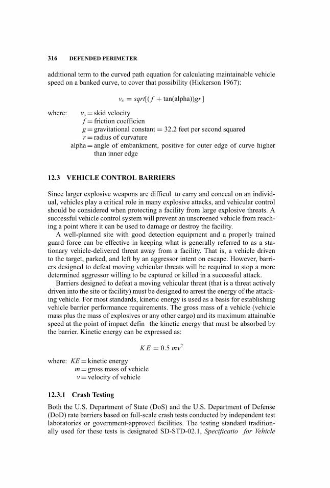
316 DEFENDED PERIMETER
additional term to the curved path equation for calculating maintainable vehiclespeed on a banked curve, to cover that possibility (Hickerson 1967):
vs = sqrt[( f + tan(alpha))gr ]
where: vs = skid velocityf = friction coefficieng= gravitational constant = 32.2 feet per second squaredr= radius of curvature
alpha= angle of embankment, positive for outer edge of curve higherthan inner edge
12.3 VEHICLE CONTROL BARRIERS
Since larger explosive weapons are difficul to carry and conceal on an individ-ual, vehicles play a critical role in many explosive attacks, and vehicular controlshould be considered when protecting a facility from large explosive threats. Asuccessful vehicle control system will prevent an unscreened vehicle from reach-ing a point where it can be used to damage or destroy the facility.
A well-planned site with good detection equipment and a properly trainedguard force can be effective in keeping what is generally referred to as a sta-tionary vehicle-delivered threat away from a facility. That is, a vehicle drivento the target, parked, and left by an aggressor intent on escape. However, barri-ers designed to defeat moving vehicular threats will be required to stop a moredetermined aggressor willing to be captured or killed in a successful attack.
Barriers designed to defeat a moving vehicular threat (that is a threat activelydriven into the site or facility) must be designed to arrest the energy of the attack-ing vehicle. For most standards, kinetic energy is used as a basis for establishingvehicle barrier performance requirements. The gross mass of a vehicle (vehiclemass plus the mass of explosives or any other cargo) and its maximum attainablespeed at the point of impact defin the kinetic energy that must be absorbed bythe barrier. Kinetic energy can be expressed as:
K E = 0.5 mv2
where: KE= kinetic energym= gross mass of vehiclev= velocity of vehicle
12.3.1 Crash Testing
Both the U.S. Department of State (DoS) and the U.S. Department of Defense(DoD) rate barriers based on full-scale crash tests conducted by independent testlaboratories or government-approved facilities. The testing standard tradition-ally used for these tests is designated SD-STD-02.1, Specificatio for Vehicle

VEHICLE CONTROL BARRIERS 317
Crash Test of Perimeter Barriers and Gates (U.S. Department of State 1999).The DoS test standard rates the anti-ram barriers within three categories: K4,K8, and K12. The K rating corresponds to the kinetic energy of the impactingvehicle at the moment of impact. A K12 rating corresponds to impact energy of1,200,000 ft-lb. These tests are conducted using a flatbe truck with a designatedmass of 15,000 lb. The standard originally provided an additional L rating thatdesignated the level of penetration achieved by the vehicle. However, in March2003, with the release of Revision A, acceptable penetration was limited to 1 m,eliminating the need for an L rating. All previous barriers where the penetrationexceeded 1 m were designated unacceptable by the revised standard, and the Lrating was dropped from use. While significan penetration is not allowed bythe DoS standards, penetration may be permitted in other applications especiallywhere large setback is available.
ASTM has also developed a test standard, with input from both the U.S. De-partment of State and the U.S. Department of Defense, that is beginning to growin acceptance in the barrier industry. This standard, Standard Test Method forVehicle Crash Testing of Perimeter Barriers (ASTM F2656-07) is likely to growin use and is gradually being accepted by both the U.S. Department of State andthe U.S. Department of Defense.
12.3.2 Crash Modeling
There is no one-to-one correlation between the kinetic energy and a static designload. The impact forces vary significantl through time and are a function of thecrushing of the vehicle as well as the strength and stiffness of the barrier. Onemethod for calculating barrier response is to equate the energy in the vehicle(KE) with the work done on the barrier and the vehicle:
KE = Wb +WvWb = ∫
F(x) · dxbWv = ∫
F(x) · dxvwhere: KE= kinetic energy
Wb =work done on the barrierWv =work done on the vehicleF= force generated between the barrier and the vehiclexb = displacement of the barrierxv = displacement of the vehicle
Calculating work on the barrier and the vehicle depends on obtaining goodforce and displacement histories. This is difficul to accomplish with simplemodels, given the complex interactions that occur between the barrier and thedeforming vehicle during impact. A conservative simplifie analysis can be per-formed using a single-degree-of-freedom (SDOF) model of the barrier, if thework done on the vehicle is set to zero. However, an SDOF design will generally
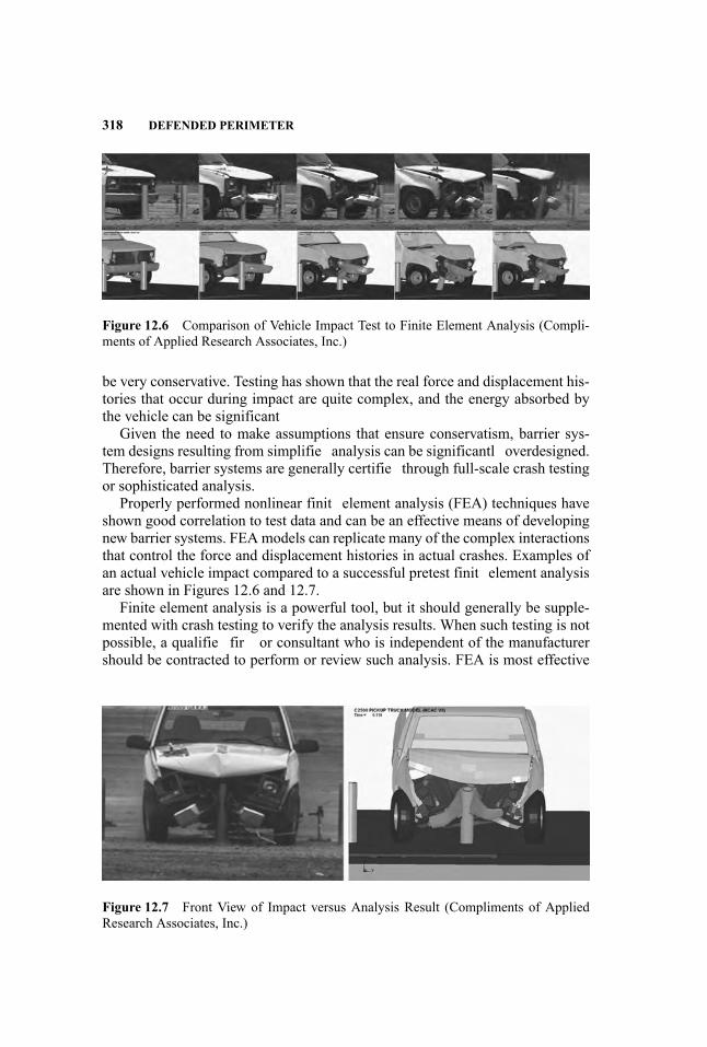
318 DEFENDED PERIMETER
Figure 12.6 Comparison of Vehicle Impact Test to Finite Element Analysis (Compli-ments of Applied Research Associates, Inc.)
be very conservative. Testing has shown that the real force and displacement his-tories that occur during impact are quite complex, and the energy absorbed bythe vehicle can be significant
Given the need to make assumptions that ensure conservatism, barrier sys-tem designs resulting from simplifie analysis can be significantl overdesigned.Therefore, barrier systems are generally certifie through full-scale crash testingor sophisticated analysis.
Properly performed nonlinear finit element analysis (FEA) techniques haveshown good correlation to test data and can be an effective means of developingnew barrier systems. FEAmodels can replicate many of the complex interactionsthat control the force and displacement histories in actual crashes. Examples ofan actual vehicle impact compared to a successful pretest finit element analysisare shown in Figures 12.6 and 12.7.
Finite element analysis is a powerful tool, but it should generally be supple-mented with crash testing to verify the analysis results. When such testing is notpossible, a qualifie fir or consultant who is independent of the manufacturershould be contracted to perform or review such analysis. FEA is most effective
Figure 12.7 Front View of Impact versus Analysis Result (Compliments of AppliedResearch Associates, Inc.)

VEHICLE CONTROL BARRIERS 319
Figure 12.8 Low Wall (Compliments of Applied Research Associates, Inc.)
when the analyst has access to crash test data for similar systems and vehicles inorder to validate the FEA model performance. Therefore, the more the proposedsystem differs from known test parameters, the more doubt and scrutiny shouldbe given to the results. Ideally, the analyst will be able to provide FEA resultsthat demonstrably replicate tests for similar barrier systems.
12.3.3 Walls
Walls and retaining walls, in particular, are some of the most robust crash bar-rier systems available. Commercial wall systems are available that have beendesigned and tested to stop a 60,000-lb vehicle traveling at 50 mph (KE =5,000,000 ft-lb). Reinforced concrete is a common construction material forcrash-rated walls. The wall thickness is generally between 12 and 24 inches.Crash-rated walls have traditionally risen 36 inches above grade, but recent test-ing and analysis have supported the use of 30-inch-tall barriers for stopping typ-ical cars and some trucks. Figure 12.8 illustrates what can happen when the wallheight is set too low.
12.3.4 Bollards
Bollards are one of the most common vehicle barrier systems in use. Bollardsare usually cylindrical posts spaced close enough to prevent vehicle passage andare typically constructed of steel pipe anchored in a reinforced concrete founda-tion. A few bollard systems are designed with foundations less than 1 foot deep,but most have deeper foundations. Four feet is typical. Bollard spacing is alsofrequently set at 4 ft, but bollards can in many cases be effective at spacing upto 5 ft. Spacings beyond 5 ft are generally avoided, since small cars or trucks arecapable of squeezing between bollards spaced farther than 5 ft apart. A typicalpassive bollard design is shown in Figure 12.9.
The bollard shown is capable of a K4 rating. K12-rated bollard designs arealso available.

320 DEFENDED PERIMETER
Figure 12.9 Eight-Inch-Diameter Fixed Bollard System
Active bollards can also be obtained. The most basic can be manually de-tached from the foundation and carried away (Figure 12.10).
The more advanced systems can be retracted into the foundation, using hy-draulic or electric motors. Figure 12.11 illustrates one such retractable hydrauli-cally operated bollard system.
12.3.5 Active Wedge
Wedges are a common type of active barrier and are capable of achieving K12ratings. Wedges are typically installed to be flus with the road surface whenlowered. When the barrier is raised to stop traffic steel plates pivot up from theroad surface to form a wedge shape. Wedges are typically operated electricallyor hydraulically. Many variations are available. Figure 12.12 illustrates one com-mon configuratio of wedge barrier.
12.3.6 Beam Barriers
Beam barriers generally swing, pivot, or slide out of the path of the vehicle topermit traffi fl w. Beam barriers generally do not achieve impact ratings as highas those of other active wedge barriers, but they generally cost significantl lessand are easier to operate. The photo in Figure 12.13 shows a beam barrier.
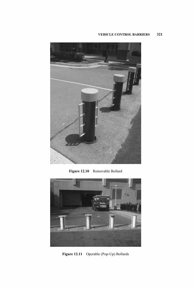
VEHICLE CONTROL BARRIERS 321
Figure 12.10 Removable Bollard
Figure 12.11 Operable (Pop-Up) Bollards
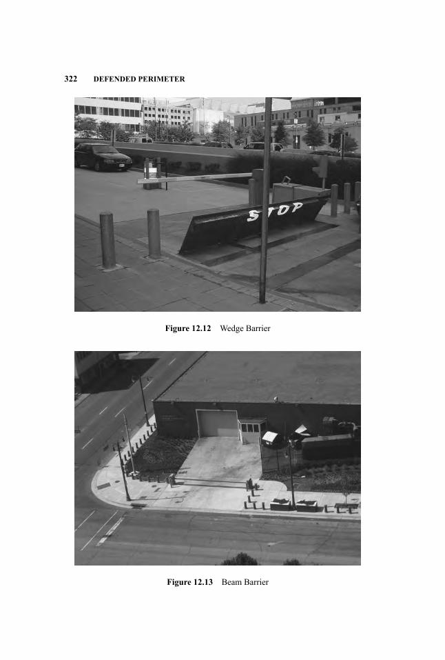
322 DEFENDED PERIMETER
Figure 12.12 Wedge Barrier
Figure 12.13 Beam Barrier

VEHICLE CONTROL BARRIERS 323
12.3.7 Cable-Based Systems
Cable-based systems generally consist of horizontally spanning steel cables an-chored to the ground through anchor posts or other means and positioned tocapture an attacking vehicle. When a cable system is impacted by a vehicle, theintermediate anchor posts respond progressively away from the point of impactuntil the vehicle is arrested. Cable-based barrier systems generally allow morepenetration than other more rigid barrier systems. However, they also generallyrequire lighter or more widely spaced foundations. Another advantage of cable-based systems is their ability to absorb the energy of the impact in a fashion thatlimits vehicle damage and injury to the vehicle occupants. The anchored cablescan also be integrated into various fence systems to prevent intrusion of peopleas well as vehicles. See Figure 12.14.
Cable barriers are a good choice for large perimeters where a few feet ofpenetration is acceptable in exchange for reduced installation costs. Cable-basedsystems are most effective for protecting long stretches of perimeter, since they
Figure 12.14 Cable Fence Barrier

324 DEFENDED PERIMETER
Figure 12.15 Concrete Planter
perform best when splice points are widely spaced. Fences with cables arecommon at airports throughout the United States. These systems are generallyvulnerable to impacts near corners and ends, where the impact forces cannot betransferred to adjacent anchor posts through tensile-membrane action. Specialdetailing or supplemental barriers may be required near corners to ensure aconsistent level of protection.
Active cable-based systems also exist and typically consist of a cable net thatspans the road to prevent traffi fl w. The cables can be relaxed to allow vehiclesto pass over the cable net or tensioned to activate the barrier.
12.3.8 Planter and Surface Barriers
Surface barriers typically consist of large containers fille with soil, water, sand,or some other readily available material. One of the more common and aestheti-cally pleasing barriers in this category is concrete planters (see Figure 12.15).
True surface barriers (ones that do not include a foundation) initially absorbthe energy of impact through momentum transfer and must have significanmass to perform well. Lighter surface barrier systems may allow significanpenetration before stopping a vehicle. Figure 12.16 shows the aftermath of areal-world collision with a relatively lightweight planter system. In this case, theplanter was driven nearly to the building before coming to a full stop. Ground orconcrete anchors are available for such systems and will significantl reduce thepenetration distance.
12.3.9 Berms, Ditches, and Other Landscaping Features
Berms, ditches, and hillside cuts, as well as trees, boulders, and other largeobjects can be effectively used to stop vehicles from penetrating a restricted
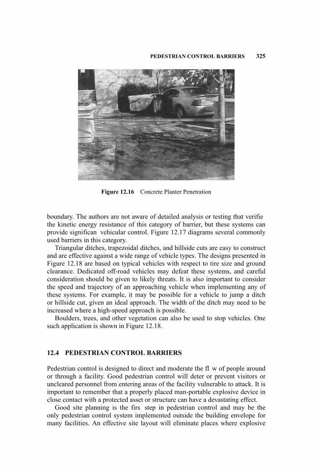
PEDESTRIAN CONTROL BARRIERS 325
Figure 12.16 Concrete Planter Penetration
boundary. The authors are not aware of detailed analysis or testing that verifiethe kinetic energy resistance of this category of barrier, but these systems canprovide significan vehicular control. Figure 12.17 diagrams several commonlyused barriers in this category.
Triangular ditches, trapezoidal ditches, and hillside cuts are easy to constructand are effective against a wide range of vehicle types. The designs presented inFigure 12.18 are based on typical vehicles with respect to tire size and groundclearance. Dedicated off-road vehicles may defeat these systems, and carefulconsideration should be given to likely threats. It is also important to considerthe speed and trajectory of an approaching vehicle when implementing any ofthese systems. For example, it may be possible for a vehicle to jump a ditchor hillside cut, given an ideal approach. The width of the ditch may need to beincreased where a high-speed approach is possible.
Boulders, trees, and other vegetation can also be used to stop vehicles. Onesuch application is shown in Figure 12.18.
12.4 PEDESTRIAN CONTROL BARRIERS
Pedestrian control is designed to direct and moderate the fl w of people aroundor through a facility. Good pedestrian control will deter or prevent visitors oruncleared personnel from entering areas of the facility vulnerable to attack. It isimportant to remember that a properly placed man-portable explosive device inclose contact with a protected asset or structure can have a devastating effect.
Good site planning is the firs step in pedestrian control and may be theonly pedestrian control system implemented outside the building envelope formany facilities. An effective site layout will eliminate places where explosive
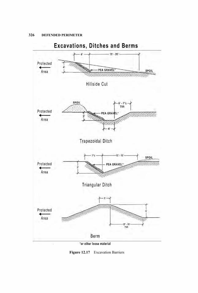
326 DEFENDED PERIMETER
Figure 12.17 Excavation Barriers
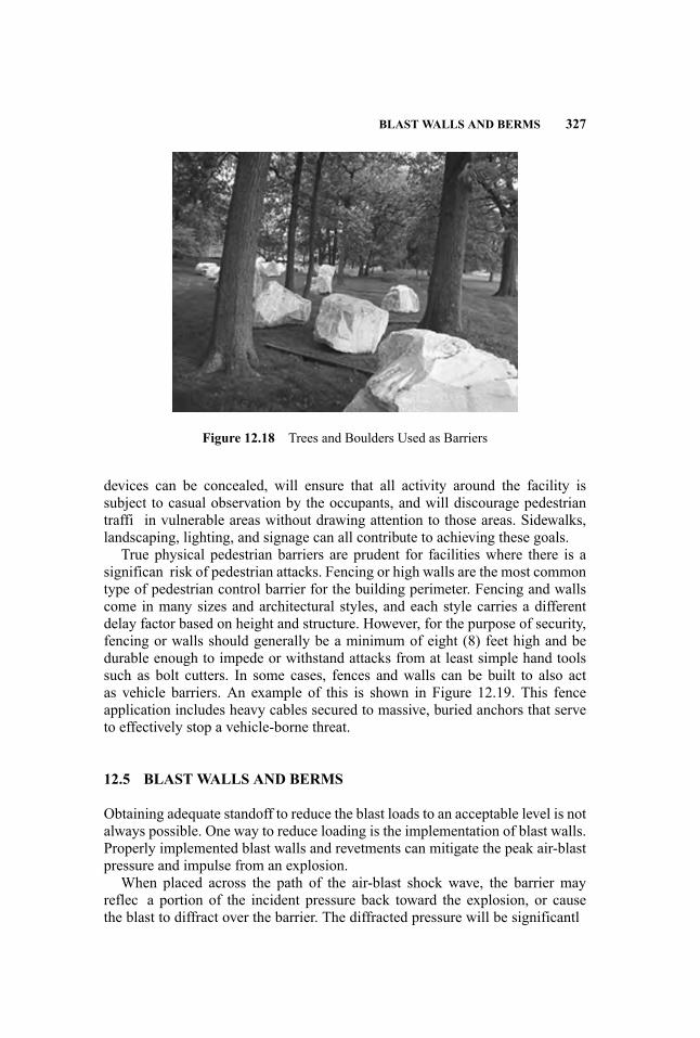
BLAST WALLS AND BERMS 327
Figure 12.18 Trees and Boulders Used as Barriers
devices can be concealed, will ensure that all activity around the facility issubject to casual observation by the occupants, and will discourage pedestriantraffi in vulnerable areas without drawing attention to those areas. Sidewalks,landscaping, lighting, and signage can all contribute to achieving these goals.
True physical pedestrian barriers are prudent for facilities where there is asignifican risk of pedestrian attacks. Fencing or high walls are the most commontype of pedestrian control barrier for the building perimeter. Fencing and wallscome in many sizes and architectural styles, and each style carries a differentdelay factor based on height and structure. However, for the purpose of security,fencing or walls should generally be a minimum of eight (8) feet high and bedurable enough to impede or withstand attacks from at least simple hand toolssuch as bolt cutters. In some cases, fences and walls can be built to also actas vehicle barriers. An example of this is shown in Figure 12.19. This fenceapplication includes heavy cables secured to massive, buried anchors that serveto effectively stop a vehicle-borne threat.
12.5 BLAST WALLS AND BERMS
Obtaining adequate standoff to reduce the blast loads to an acceptable level is notalways possible. One way to reduce loading is the implementation of blast walls.Properly implemented blast walls and revetments can mitigate the peak air-blastpressure and impulse from an explosion.
When placed across the path of the air-blast shock wave, the barrier mayreflec a portion of the incident pressure back toward the explosion, or causethe blast to diffract over the barrier. The diffracted pressure will be significantl
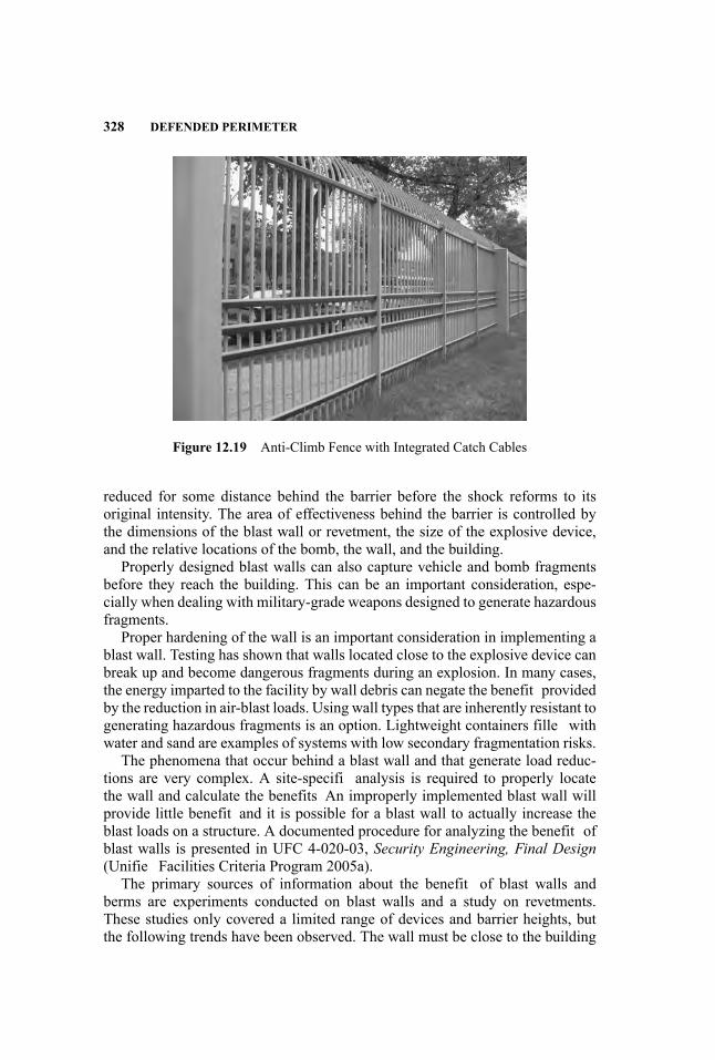
328 DEFENDED PERIMETER
Figure 12.19 Anti-Climb Fence with Integrated Catch Cables
reduced for some distance behind the barrier before the shock reforms to itsoriginal intensity. The area of effectiveness behind the barrier is controlled bythe dimensions of the blast wall or revetment, the size of the explosive device,and the relative locations of the bomb, the wall, and the building.
Properly designed blast walls can also capture vehicle and bomb fragmentsbefore they reach the building. This can be an important consideration, espe-cially when dealing with military-grade weapons designed to generate hazardousfragments.
Proper hardening of the wall is an important consideration in implementing ablast wall. Testing has shown that walls located close to the explosive device canbreak up and become dangerous fragments during an explosion. In many cases,the energy imparted to the facility by wall debris can negate the benefit providedby the reduction in air-blast loads. Using wall types that are inherently resistant togenerating hazardous fragments is an option. Lightweight containers fille withwater and sand are examples of systems with low secondary fragmentation risks.
The phenomena that occur behind a blast wall and that generate load reduc-tions are very complex. A site-specifi analysis is required to properly locatethe wall and calculate the benefits An improperly implemented blast wall willprovide little benefit and it is possible for a blast wall to actually increase theblast loads on a structure. A documented procedure for analyzing the benefit ofblast walls is presented in UFC 4-020-03, Security Engineering, Final Design(Unifie Facilities Criteria Program 2005a).
The primary sources of information about the benefit of blast walls andberms are experiments conducted on blast walls and a study on revetments.These studies only covered a limited range of devices and barrier heights, butthe following trends have been observed. The wall must be close to the building
REFERENCES 329
or the explosive charge to achieve useful load reductions. For walls placedclose to the charge, peak pressures are reduced dramatically directly behindthe wall but gradually approach the free-fiel blast at large distances. There aresome combinations of large distances between the bomb and the wall and shortdistances between the wall and the building that may cause an increase in thereflecte impulse due to multiple reflection of the blast wave between the walland the structure.
The shape of the wall or barrier and its height have a significan effect on theload reduction. Walls and revetments with faces oriented perpendicular to theshock wave (and the ground surface) should be a goal, since this arrangementprovides by far the most benefit Mounded or sloped barricades (i.e., typical bermconstruction) provide little reduction in blast loads.
The current blast wall data are based on situations where the wall height wasselected by taking the cube root of the charge weight in pounds and multiplyingby values between 0.8 ft and 1.3 ft. For example, the cube root of 500 lb is 7.9.Therefore, 6-ft to 10.5-ft walls fall within the range of the data. Trends in thedata show that the wall is most effective if the bomb is within 1 wall height ofthe wall and within approximately 10 wall heights of the building. Ranges fromthe wall to the building greater than 20 wall heights generally result in negligiblereductions.
REFERENCES
Hickerson, Thomas F. 1967. Route Location and Design (5th ed.) New York: McGrawHill.
Smith, Joseph L. et al. 2005. Protective Design and Security Implementation Guidelines.Prepared by Applied Research Associates, Inc. for the U.S. General Services Admin-istration.
Unifie Facilities Criteria Program. 2005a. Security Engineering, Final Design (UFC4-020-03). Washington, DC: U.S. Department of Defense, Unifie Facilities CriteriaProgram.
. 2005b. Selection and Application of Vehicle Barriers (UFC 4-022-02). Wash-ington, DC: U.S. Department of Defense, Unifie Facilities Criteria Program.
. 2008. Structures to Resist the Effects of Accidental Explosions (UFC 3-340-02). Washington, DC: U.S. Department of Defense, Unifie Facilities Criteria Program.
U.S. Department of State. 1999. Specificatio for Vehicle Crash Test of Perimeter Barri-ers and Gates (SD-STD-02.1). Washington, DC: U.S. Department of State.
13 Blast-Resistant Design ofBuilding Systems
Scott Campbell and James Ruggieri
13.1 BACKGROUND
Public awareness of the need to protect structures against blast effects has risensharply since September 11, 2001. A number of public agencies are engagedin research and development of blast-resistant technology, and its application todomestic and foreign structures that are potential targets of terrorist activity. Thefederal agency responsible for developing technology in this area is the DefenseSpecial Weapons Agency/Technical Support Working Group (DSWA/TSWG),which receives funding from Congress through Department of Defense (DoD)appropriations. This funding is used to support physical testing of candidateblast-resistant design concepts, computational modeling, and understandingof phenomenology. A range of government agencies and private consultantsparticipates in the program, whose results are available to the General ServicesAdministration (GSA), the DOD, and other U.S. and foreign governmentagencies. The technology derived from this and similar previous programs iscurrently being implemented for the protection of U.S. Secret Service headquar-ters and FBI laboratory in the Washington, D.C.. area, the federal courthousein Brooklyn, NY, and the passenger terminal at Midway Airport, Chicago, toname only a few locations. The U.S. State Department plans to request between$1 and $3 billion to raise security at U.S. embassies to the standards set by theDepartment in the 1980s.
The events of 9/11, as well as similar follow-on events, have introducednew performance requirements for all building systems. New performancerequirements for such structures have introduced a need to revisit and modifythe traditional assumptions governing building design. New systems, includingatmosphere segregation systems (i.e., positive pressure, collective protection,and hazardous agent monitoring systems, etc.) as well as changes to theenvironment, including consideration to blast and shock, introduce constraintsnot previously considered in the design development of building mission andlife-safety systems.
331
Handbook for Blast-Resistant Design of Buildings Edited by Donald 0. Dusenberry
Copyright 0 2010 by John Wiley & Sons, Inc. All rights reserved.

332 BLAST-RESISTANT DESIGN OF BUILDING SYSTEMS
Although existing commercial consensus standards, such as NFPA 70A (Na-tional Fire Protection Association 2005), have historically performed well forgeneral “nontarget” buildings and facilities, they do not address the special con-siderations now facing “target” buildings and facilities serving critical infrastruc-ture needs. Therefore, new practical and readily expedient methods need to beidentifie that could better fulfil this new environment.
13.2 INTRODUCTION
The detonation of explosives near or in a building affects not only the buildingfacade and structure, but also the building contents. In seismic events, theimprovement in earthquake-resistant structural design has led to a significandecrease in structural damage. However, the result is that nonstructural damagenow accounts for a majority of the costs associated with earthquakes. Similarly,increasing the blast resistance of building structures will reduce the associateddamage, but may increase the relative importance of nonstructural componentdamage. Significantl , a building may be structurally undamaged, but rendereduseless due to damage to HVAC, electrical, plumbing, and other systems.Therefore, a balanced design approach is suggested wherein the buildingsystems are designed to withstand either the appropriate blast loads or resultingstructural movements.
Very little information is available regarding the design of building systems toresist the effects of explosions. This lack of design guidance has resulted in theuse of better-developed seismic guidelines, such as the Uniform Building Code(UBC) (International Code Council 1997) or International Building Code (IBC)(International Code Council 2006), the use of extremely conservative designs,or the neglect of the protection of equipment and systems. Traditionally, equip-ment has been designed for blast by being placed in shelters or internal to thebuilding and checking acceleration resistance against expected levels. This re-mains the best practice, although particularly rugged equipment—for examplepumps—may be left exposed with anchorage designed for the applied loads.
Third-party testing by nationally accredited conformity assessment organiza-tions, such as Underwriters Laboratories (UL), is often used to verify certain per-formance characteristics of a system element. Traditional testing often includesverificatio of desired material properties such as strength, ductility, chemistry,and composition; and random sampling procedures are used to audit perfor-mance of the subject components for use, in comparison to design requirementsand/or regulation. Examples of this include equipment operability, controllabil-ity and speed, current-carrying capacity, insulation resistance, power required,power developed, vibration, and many others. In most cases, the requirements in-voked for electrical equipment and devices used in building systems only addresselectrical shock safety (e.g., electrocution risk) and risk of fire However, suchcriteria presume a benign environment, not subject to risk of blast. The standards

DESIGN CONSIDERATIONS 333
and building code organizations readily admit that such documents only identifya consensus for a common denominator that speaks to the minimum acceptableperformance or criteria, assuming a safe and relatively comfortable environment.Such documents do not address blast. Although there is one U.S. national stan-dards development activity presently underway to provide enhanced criteria toharden building electrical systems to the effects of blast—ASCE/AEI Recom-mended Hardening Techniques for Control, Communication and Power (C2P)Systems of Critical Facilities—there is nothing available in the nonmilitary com-munity at this time that can be used for design guidance.
Explosions generate loads on building systems through three basic mecha-nisms. Direct blast pressures can impact systems exterior to the building fromexplosions outside the building envelope and from internal explosions. Indirectpressures are generated when a blast external to the space where the equip-ment is located leaks into the room through openings. Finally, ground shock andair shock generate loads on building systems through motions developed in thestructure. All three types of loads are considered in this chapter. Note also thatfragments can pose a severe threat to building systems and equipment. However,calculation of fragmentation and the resulting damage to nonstructural compo-nents is beyond the scope of this section (see Chapter 8).
The general design approach for building systems is to determine the loadlevels, both blast pressures and base accelerations, for the chosen location. Theequipment and anchorage capacities are then checked against the design load.If the equipment’s allowable load is exceeded, then either it must be moved orprotected. Each of these steps is detailed in subsequent sections of this chapter.
13.3 DESIGN CONSIDERATIONS
The key philosophy for providing continuity of services for mechanical and elec-trical systems in buildings is SHR: Separation, Hardening, and Redundancy.Segregation of critical and vital circuits from normal services provides designeconomy, since hardening-type construction methods can be focused on onlythose specialized areas. Judicious use of steel conduits, pipes, and ducts asso-ciated with life-safety systems provides increased likelihood of survivability forthese systems, and a greater likelihood that emergency systems will remain op-erational post-event to assist rescuers in the evacuation of the building, and/orprovide continuity of critical business services.
Although each design situation is unique, it is possible to provide some gen-eral guidance regarding blast-resistant design of equipment and systems. Thissection will discuss choosing appropriate design goals, specifi points of con-cern for the different loads that can be imposed, and some guidelines regardingselect types of equipment and systems. However, good engineering practice andjudgment are the best approach for these situations, given the amount of uncer-tainty present in this field

334 BLAST-RESISTANT DESIGN OF BUILDING SYSTEMS
13.3.1 Level of Protection
A critical step in the design of building systems for blast load is to determinethe goal of hardening. In general, there are two levels of performance normallyconsidered in system blast-resistant design:
1. Life Safety: Also called position retention. This design level is intended tokeep the equipment in place, with no large pieces or components comingloose and potentially injuring personnel. The equipment or system is notexpected to remain operational after the event.
2. Continued Operation: As the name implies, the equipment is expected toremain operational after the event. This might entail resetting the equip-ment, but no major repairs should be required to maintain basic operationalcapabilities.
Continued operation of equipment subjected to blast or shock loads is oftendifficul to predict. Seemingly minor failures can lead to a shutdown and lossof critical systems. In general, only inherently rugged equipment can be consid-ered for continued operation if directly exposed to blast pressures. Less ruggedequipment may be designed to remain operational for reduced pressures due toprotection by shelters or interior location. If the continued operation of a systemis required, it is essential that all aspects of the loading condition be considered,and testing of the equipment is likely to be necessary.
The life-safety level of design is easier to achieve, as no evaluation of theworking parts of the equipment is required. It is only necessary to analyze theequipment structure and anchorage. Note, however, that the analysis includes allexternal components, including the sheet metal shell of the equipment, if any, toensure that they remain attached to the equipment. Large internal componentsthat have the ability to break out of the shell must also be considered. Anotherresponse quantity that must be considered for suspended systems is deflectionsA system may be capable of resisting the pressure or acceleration load on itsown, but large deflection may cause an impact with other equipment and leadto an anchorage or equipment failure.
13.3.2 Blast Pressures
The best way to protect equipment and systems from the effects of blast is tolocate them in areas protected from direct air blast. If the building envelope isproperly designed to resist blast effects, location of equipment in mechanicalrooms without openings to the exterior of the building will preclude pressureloading from external events. However, equipment that is located inside protec-tive structures will often be subjected to blast pressure that leaks in through open-ings in the walls and/or roof. Likewise, properly securing hardened mechanicalrooms, and thus limiting access to authorized personnel, will significantl reducethe likelihood of internal blast loads on the equipment. However, concentrating

DESIGN CONSIDERATIONS 335
mechanical equipment in a single location will render the overall system morevulnerable to unauthorized access if proper precautions are not maintained.
Removal of equipment from vulnerable areas is not always possible, and islikely not feasible for all distributed systems. In these situations, it is necessary torequire design to higher than desired levels of pressure loading. This may entailproviding barrier walls, if not complete shelters, or testing equipment to the an-ticipated design load. Particularly critical distributed systems may be enclosed inhardened runways, or redundant systems located elsewhere in the building maybe provided. Obviously, these additional precautions can be extremely expen-sive, and care should be taken early in the design process to eliminate or reduceto a minimum the number and types of systems that require special design.
13.3.3 Shock Induced by the Structure
The impact of blast-generated air and ground shock on the structure will producemotions that are potentially damaging to the building systems. The resultingstructural accelerations can be estimated using the methods outlined later inthis chapter. After the structural motions are calculated, the resistance of theequipment to shock loads can be checked. Typical values of equipment shockresistance are given in Table 13.1. One major caveat applies to the use of thesevalues. In many cases they are based on testing that is decades old. In the interimmany changes have occurred in the design of some equipment. The tabulatedvalues may no longer be applicable, and caution should be used in applyingthem to modern equipment. Significan testing is often required for equipmentused in the military and the nuclear industry, and manufacturers may be ableto provide capacities for specifi pieces of equipment. The nuclear industrySeismic Qualificatio Utility Group (SQUG) has a large database of equipmentresponse during earthquakes, but these data are not generally available tothe public.
A common practice is to specify design loads for the equipment in terms of anequivalent earthquake load. This is particularly true where it is desirable that theactual load source remain confidential It is perfectly acceptable to give only anequivalent “g” acceleration value. The acceleration level to be specifie can bedetermined using the methods detailed in Chapter 7 or a more detailed calcula-tion that considers the stiffness and mass distribution in the structure. However,there are several caveats that must be observed.
First, unless a dynamic analysis of the building is performed and the flooaccelerations specifie as time histories, the frequency content of the input mo-tion to the equipment is lost. Second, it is not correct to specify a design to,for example, 0.75g using the 2006 International Building Code (IBC). The IBCmethod is used to determine earthquake loads for anchorage design and equip-ment qualification A base ground acceleration is used that is then modifie toaccount for location within the building, natural frequency of the equipment,ability of the equipment to undergo nonlinear deformations without failure, andthe importance of the equipment.

336 BLAST-RESISTANT DESIGN OF BUILDING SYSTEMS
Table 13.1 Selected Equipment/System Fragility Level Guidelines (ASHRAE2007)
Accelerations (g)
Equipment/System Type No Damage Probable Minor Damage Probable
Pumps up to 100 hp 4.5 8Control Panels 3.5 8Fans up to 100 hp 4 9Welded steel piping (18 in. dia max, Sch30 and up)
4 8
Air-handling units 4.5 10Duct, steel 4.5 9Motor control centers 2.5 N/AUninterruptible power supplies 3 N/ACable trays (up to 36 in.) 4.5 8ChillersCentrifugal 4 N/AAbsorption 4.5 N/AScrew 3.5 N/AAir-cooled 3.0 N/A
Boilers 3.5 N/A
There are several contributing factors as to why it is not good practice toapply this methodology to in-structure shock loads. First, earthquake loads onequipment depend not only on the size of the earthquake, but also on the verticallocation within the building. If the floo accelerations have been determined, andthat is what is being specified it must be made clear that the factor for verticallocation (an increase in load of as much as three times) should be disregarded inthe calculation. It is also not clear if the other factors are applicable. However, themost critical point is that many parts of the country are exempt from providingseismic restraint to equipment regardless of the specifie acceleration level. Forthese reasons it is best to provide an acceleration level, either ground or floolevel; require use of the building code load equation as appropriate; and explicitlystate that no exemptions are permitted.Shock Isolation: Isolation of equipment to reduce the effects of shock load-
ing has been used successfully on many projects. Isolation systems work onthe principle that if the loading and isolation system’s natural frequencies varygreatly, the isolated equipment will undergo motions much less severe than thebase structure. The amount the motion is reduced depends upon the ratio of theforcing frequency to the natural frequency of the isolation system (frequencyratio), as illustrated in Figure 13.1. Thus, to achieve a high level of reduction,the isolation system should have a much lower natural frequency than the input

DESIGN CONSIDERATIONS 337
Figure 13.1 Transmissibility of Motion for Isolated Systems with 5% Damping
motion. However, this leads to a soft isolation system (low stiffness) and poten-tially high static deformations and problems with coupling between displacementand rotation deformation modes. A balanced system using a properly selectedisolator, additional weight (inertia mass), and possibly supplemental dampingcan help to alleviate the problems associated with soft isolation systems.
There are several types of isolators that are commonly used, includingsteel springs, wire coils, air-springs, elastomeric mounts, and damping devices(Figure 13.2). Most of the isolators can be used in either direct-mounted configurations, where the inertia mass and equipment are placed on top of the isolators,or in a pendulum configuratio where the load is hung from the isolators. Ineither case, the systems are designed to carry the gravity load and accommodatethe deformations expected during a shock load. The equipment thus remainsrelatively motionless while the supporting floo undergoes large motions, withthe isolation system deforming while maintaining vertical load capacity. Shockisolation systems are available from a number of manufacturers who providedesign services along with the isolation systems. The project engineer mustdetermine the level of isolation required and the input motions, while themanufacturer will choose the correct isolator to achieve the desired results.
13.3.4 Equipment/System Anchorage
The anchorage of equipment to the structure must be checked for all loadingcases and desired levels of performance. The procedure is relatively simple: An-alytically apply the load to a mathematical model of the equipment, calculate
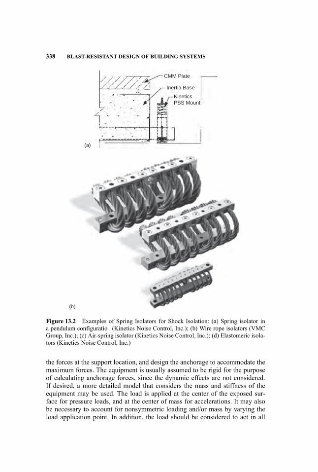
338 BLAST-RESISTANT DESIGN OF BUILDING SYSTEMS
CMM Plate
Inertia Base
KineticsPSS Mount
(a)
(b)
Figure 13.2 Examples of Spring Isolators for Shock Isolation: (a) Spring isolator ina pendulum configuratio (Kinetics Noise Control, Inc.); (b) Wire rope isolators (VMCGroup, Inc.); (c) Air-spring isolator (Kinetics Noise Control, Inc.); (d) Elastomeric isola-tors (Kinetics Noise Control, Inc.)
the forces at the support location, and design the anchorage to accommodate themaximum forces. The equipment is usually assumed to be rigid for the purposeof calculating anchorage forces, since the dynamic effects are not considered.If desired, a more detailed model that considers the mass and stiffness of theequipment may be used. The load is applied at the center of the exposed sur-face for pressure loads, and at the center of mass for accelerations. It may alsobe necessary to account for nonsymmetric loading and/or mass by varying theload application point. In addition, the load should be considered to act in all
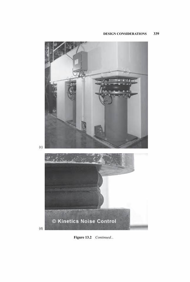
DESIGN CONSIDERATIONS 339
(c)
(d)
Figure 13.2 Continued...

340 BLAST-RESISTANT DESIGN OF BUILDING SYSTEMS
possible directions. Note that this is not simply all directions, as in seismic de-sign, since the explosive location may be restricted and therefore limit the loaddirection. All seismic design guidelines should be observed regarding limitationson the type of anchors. For example, power-actuated fasteners should not be usedunless specificall qualified and undercut anchors are required for equipmentover 10 hp that is not vibration-isolated. In addition, the structural component towhich the equipment is mounted must also be capable of carrying the anchorageforce. Details on the anchorage calculations are provided in the design examples.
13.3.5 Placement of Critical Systems Equipment and Control Stations
Unsecured areas such as the lobby, loading dock, mailroom, garage, retail, andother public access areas must be separated from the secured areas of the build-ing, particularly areas of a building housing switchgear, computer server datacenters, centralized command centers, and machinery plant control and monitor-ing stations. Ideally, unsecured areas are placed exterior to the main building oralong the edges of the building. Occupied areas or areas providing emergencyor critical functions should not be placed immediately adjacent to the lobby, butshould be separated by a substantive buffer area such as a storage area or corridor.From an operational security standpoint, it is important to restrict and control ac-cess to air-intake louvers, mechanical and electrical rooms, telecommunicationsspaces, and rooftops by means of such measures as visitor screening, limited ele-vator stops, closed-circuit television (CCTV), detection, and card access-controlsystems.
13.3.6 Staffin and Building Operations
How building staffin (i.e., managers, maintenance crew, boiler-men, securitypersonnel, attendants, etc.) is determined can make a substantial difference inminimizing loss of life and minimizing injury, as well as improving the abil-ity of a facility to sustain continuity of critical services in the event of a blast.Determining staffin is integral to the design-development process of buildingsystems. For instance, automation and systems monitoring rely on certain as-sumptions regarding staffing Increased use of centralized equipment/systemshealth-determining methods, such as computerized condition-based monitoring(vibration, temperature, differential pressures, etc.) significantl reduces the needfor periodic roving manned inspections.
An excellent model for effective staffin can be taken from the military. U.S.warships are designed to absorb a certain number of strikes to minimize loss oflife, ensure continued reliable maneuvering and control (survival of steering gear,propulsion systems, etc.), and ensure reliable operation of both defensive andoffensive systems. Such vessels rely on an architecture of self-sufficien y usinghighly trained crews who are assigned damage control functions in addition totheir normal duties (e.g., cook and fireman) As with warships in battle, buildings
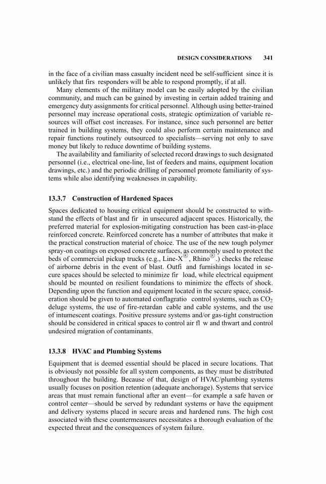
DESIGN CONSIDERATIONS 341
in the face of a civilian mass casualty incident need be self-sufficient since it isunlikely that firs responders will be able to respond promptly, if at all.
Many elements of the military model can be easily adopted by the civiliancommunity, and much can be gained by investing in certain added training andemergency duty assignments for critical personnel. Although using better-trainedpersonnel may increase operational costs, strategic optimization of variable re-sources will offset cost increases. For instance, since such personnel are bettertrained in building systems, they could also perform certain maintenance andrepair functions routinely outsourced to specialists—serving not only to savemoney but likely to reduce downtime of building systems.
The availability and familiarity of selected record drawings to such designatedpersonnel (i.e., electrical one-line, list of feeders and mains, equipment locationdrawings, etc.) and the periodic drilling of personnel promote familiarity of sys-tems while also identifying weaknesses in capability.
13.3.7 Construction of Hardened Spaces
Spaces dedicated to housing critical equipment should be constructed to with-stand the effects of blast and fir in unsecured adjacent spaces. Historically, thepreferred material for explosion-mitigating construction has been cast-in-placereinforced concrete. Reinforced concrete has a number of attributes that make itthe practical construction material of choice. The use of the new tough polymerspray-on coatings on exposed concrete surfaces, as commonly used to protect thebeds of commercial pickup trucks (e.g., Line-X R© , Rhino R© .) checks the releaseof airborne debris in the event of blast. Outfi and furnishings located in se-cure spaces should be selected to minimize fir load, while electrical equipmentshould be mounted on resilient foundations to minimize the effects of shock.Depending upon the function and equipment located in the secure space, consid-eration should be given to automated conflagratio control systems, such as CO2deluge systems, the use of fire-retardan cable and cable systems, and the useof intumescent coatings. Positive pressure systems and/or gas-tight constructionshould be considered in critical spaces to control air fl w and thwart and controlundesired migration of contaminants.
13.3.8 HVAC and Plumbing Systems
Equipment that is deemed essential should be placed in secure locations. Thatis obviously not possible for all system components, as they must be distributedthroughout the building. Because of that, design of HVAC/plumbing systemsusually focuses on position retention (adequate anchorage). Systems that serviceareas that must remain functional after an event—for example a safe haven orcontrol center—should be served by redundant systems or have the equipmentand delivery systems placed in secure areas and hardened runs. The high costassociated with these countermeasures necessitates a thorough evaluation of theexpected threat and the consequences of system failure.
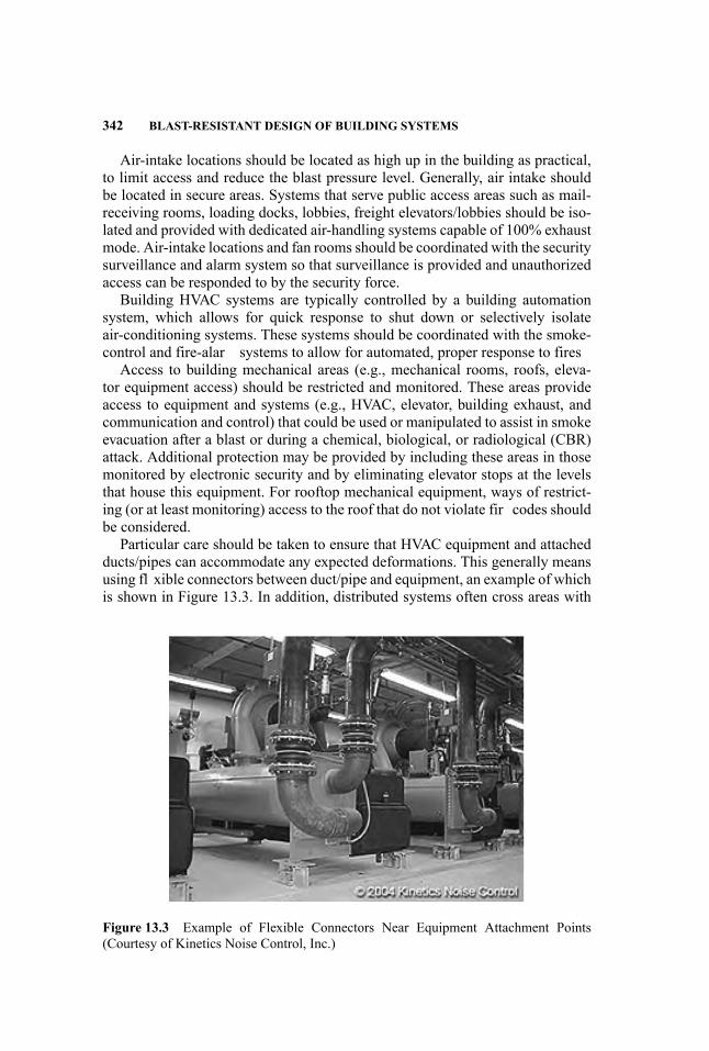
342 BLAST-RESISTANT DESIGN OF BUILDING SYSTEMS
Air-intake locations should be located as high up in the building as practical,to limit access and reduce the blast pressure level. Generally, air intake shouldbe located in secure areas. Systems that serve public access areas such as mail-receiving rooms, loading docks, lobbies, freight elevators/lobbies should be iso-lated and provided with dedicated air-handling systems capable of 100% exhaustmode. Air-intake locations and fan rooms should be coordinated with the securitysurveillance and alarm system so that surveillance is provided and unauthorizedaccess can be responded to by the security force.
Building HVAC systems are typically controlled by a building automationsystem, which allows for quick response to shut down or selectively isolateair-conditioning systems. These systems should be coordinated with the smoke-control and fire-alar systems to allow for automated, proper response to fires
Access to building mechanical areas (e.g., mechanical rooms, roofs, eleva-tor equipment access) should be restricted and monitored. These areas provideaccess to equipment and systems (e.g., HVAC, elevator, building exhaust, andcommunication and control) that could be used or manipulated to assist in smokeevacuation after a blast or during a chemical, biological, or radiological (CBR)attack. Additional protection may be provided by including these areas in thosemonitored by electronic security and by eliminating elevator stops at the levelsthat house this equipment. For rooftop mechanical equipment, ways of restrict-ing (or at least monitoring) access to the roof that do not violate fir codes shouldbe considered.
Particular care should be taken to ensure that HVAC equipment and attachedducts/pipes can accommodate any expected deformations. This generally meansusing fl xible connectors between duct/pipe and equipment, an example of whichis shown in Figure 13.3. In addition, distributed systems often cross areas with
Figure 13.3 Example of Flexible Connectors Near Equipment Attachment Points(Courtesy of Kinetics Noise Control, Inc.)
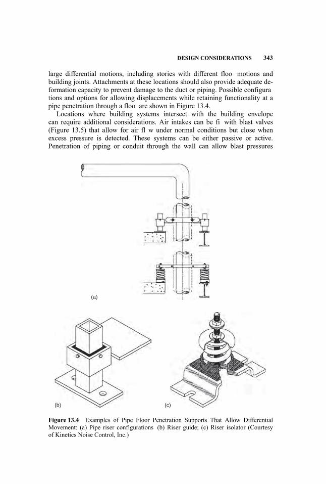
DESIGN CONSIDERATIONS 343
large differential motions, including stories with different floo motions andbuilding joints. Attachments at these locations should also provide adequate de-formation capacity to prevent damage to the duct or piping. Possible configurations and options for allowing displacements while retaining functionality at apipe penetration through a floo are shown in Figure 13.4.
Locations where building systems intersect with the building envelopecan require additional considerations. Air intakes can be fi with blast valves(Figure 13.5) that allow for air fl w under normal conditions but close whenexcess pressure is detected. These systems can be either passive or active.Penetration of piping or conduit through the wall can allow blast pressures
(a)
(c)(b)
Figure 13.4 Examples of Pipe Floor Penetration Supports That Allow DifferentialMovement: (a) Pipe riser configurations (b) Riser guide; (c) Riser isolator (Courtesyof Kinetics Noise Control, Inc.)
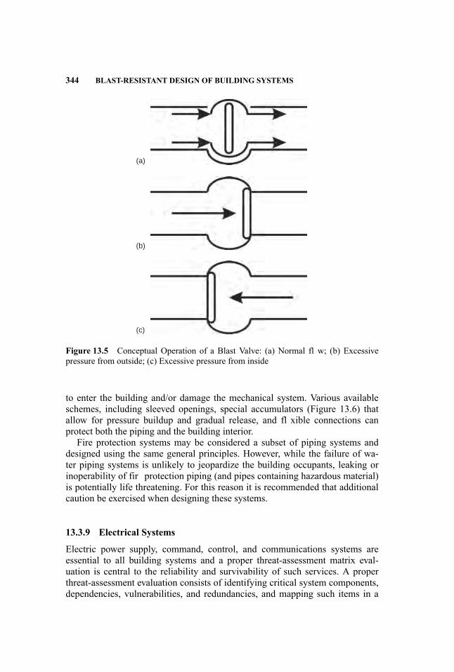
344 BLAST-RESISTANT DESIGN OF BUILDING SYSTEMS
(a)
(b)
(c)
Figure 13.5 Conceptual Operation of a Blast Valve: (a) Normal fl w; (b) Excessivepressure from outside; (c) Excessive pressure from inside
to enter the building and/or damage the mechanical system. Various availableschemes, including sleeved openings, special accumulators (Figure 13.6) thatallow for pressure buildup and gradual release, and fl xible connections canprotect both the piping and the building interior.
Fire protection systems may be considered a subset of piping systems anddesigned using the same general principles. However, while the failure of wa-ter piping systems is unlikely to jeopardize the building occupants, leaking orinoperability of fir protection piping (and pipes containing hazardous material)is potentially life threatening. For this reason it is recommended that additionalcaution be exercised when designing these systems.
13.3.9 Electrical Systems
Electric power supply, command, control, and communications systems areessential to all building systems and a proper threat-assessment matrix eval-uation is central to the reliability and survivability of such services. A properthreat-assessment evaluation consists of identifying critical system components,dependencies, vulnerabilities, and redundancies, and mapping such items in a
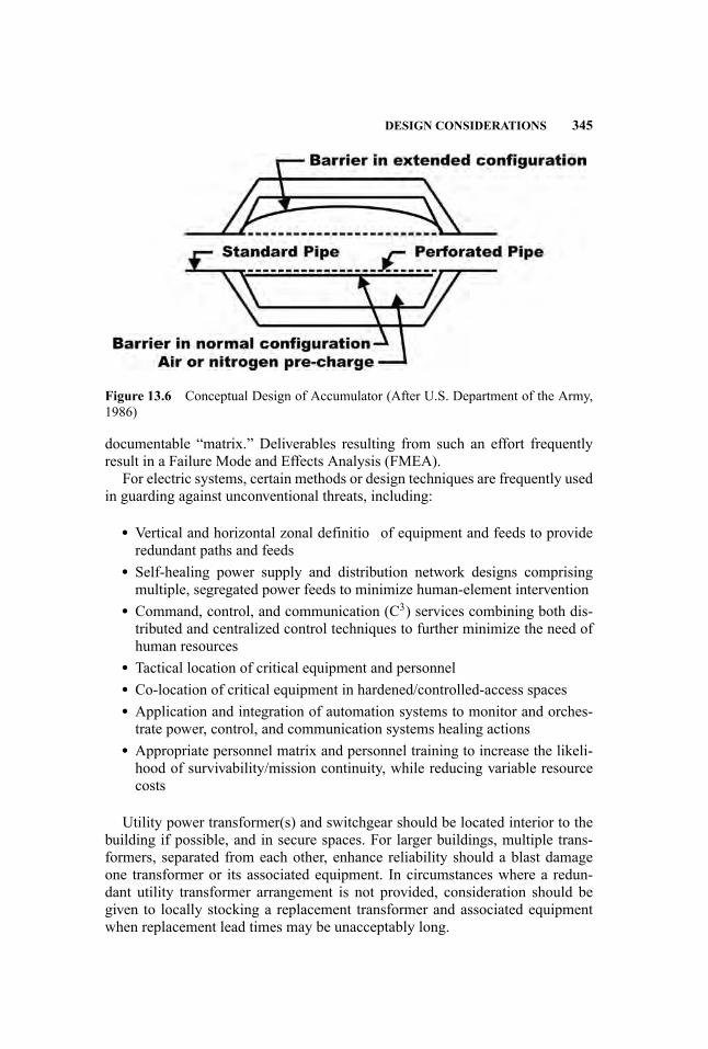
DESIGN CONSIDERATIONS 345
Figure 13.6 Conceptual Design of Accumulator (After U.S. Department of the Army,1986)
documentable “matrix.” Deliverables resulting from such an effort frequentlyresult in a Failure Mode and Effects Analysis (FMEA).
For electric systems, certain methods or design techniques are frequently usedin guarding against unconventional threats, including:
� Vertical and horizontal zonal definitio of equipment and feeds to provideredundant paths and feeds
� Self-healing power supply and distribution network designs comprisingmultiple, segregated power feeds to minimize human-element intervention
� Command, control, and communication (C3) services combining both dis-tributed and centralized control techniques to further minimize the need ofhuman resources
� Tactical location of critical equipment and personnel� Co-location of critical equipment in hardened/controlled-access spaces� Application and integration of automation systems to monitor and orches-trate power, control, and communication systems healing actions
� Appropriate personnel matrix and personnel training to increase the likeli-hood of survivability/mission continuity, while reducing variable resourcecosts
Utility power transformer(s) and switchgear should be located interior to thebuilding if possible, and in secure spaces. For larger buildings, multiple trans-formers, separated from each other, enhance reliability should a blast damageone transformer or its associated equipment. In circumstances where a redun-dant utility transformer arrangement is not provided, consideration should begiven to locally stocking a replacement transformer and associated equipmentwhen replacement lead times may be unacceptably long.
346 BLAST-RESISTANT DESIGN OF BUILDING SYSTEMS
13.3.10 Lighting Systems
Lighting system design for blast protection is similar to electrical system de-sign. The same principles of separation, zoning, emergency power supply, andso forth, all apply to lighting. One recent development that should be consideredin lighting design is the use of light-emitting diode (LED) technology. Morefrequently recognized in the electronic equipment arena, where LEDs are usedfor equipment pilot and status lights, LED technology has now evolved to offervery practical and cost-effective design alternatives in applications where incan-descent and fluorescen lamps presently dominate. With respect to susceptibilityto blast damage, LEDs stand alone as a clear leader. In addition, LED light-ing reduces the environmental impact of the lighting system and offers reducedmaintenance and increased life.
LED lighting methods do not depend on moving parts or parts that are motion-sensitive, as do incandescent and fluorescen lamp technologies (filaments stand-offs, glass, etc); that is, LEDs indeed live up to their designation as “solid-state,”and their elemental constituents, such as device leads, are solidly embedded intoinert and tough structural polymers. Their substantively smaller sizes and phys-ical profile minimize concerns related to weight and moment and susceptibilityto blast damage, while also eliminating the need for support devices/equipment(e.g., ballasts) and the weight/room required for these other support devices.
13.3.11 Other Systems/Considerations
Emergency Power System An emergency generator should be available to pro-vide an alternate source of power if utility power becomes unavailable to sup-port critical life-safety systems such as alarm systems, egress lighting fixturesexit signs, emergency communications systems, smoke-control equipment, andfir pumps. In cases where continuity of critical business missions is neces-sary, the emergency generator system can also support these missions. Practi-cally, diesel-fueled emergency generator systems are preferred over other con-ventional fuels (i.e., gasoline, propane, etc.) because of fuel availability, lowerflas point of diesel fuel, and greater power supply capacity from a relativelysmall footprint. Economically, maintenance costs are substantially lower for adiesel-driven emergency generator system when contrasted to other forms ofemergency power, including fuel cells and battery-based systems.
Emergency generators typically require large louvers to allow for ventilationand cooling of the generator. Care should be taken to locate the generator so thatthese louvers are not vulnerable to attack or are fi with blast valves. A remoteradiator system could be used to reduce the louver size and thus reduce air-intakerequirements.
Ideally, emergency power-distribution feeders are contained in hardened en-closures, or encased in concrete, and configure in redundant routing paths tominimize vulnerability and thus enhance reliability. Emergency distribution pan-els and automatic transfer switches should be located in hardened spaces isolated
DESIGN CONSIDERATIONS 347
from the normal power system. Emergency lighting fixture and exit signs alongthe egress path could be provided with integral battery packs to provide close-transition services (uninterrupted silhouette illumination) between the time theutility system fails and the emergency generator system assumes loading.
Emergency Generator System and Fuel Storage A nonexplosive fuel source,such as diesel fuel, should be considered for emergency generators and diesel-driven fir pumps. The preferred philosophy is to locate all support equipment,including the diesel fuel day tank, in the same space as the emergency generator,as a means of minimizing system dependencies. Consideration should be givento locating the emergency generator day tank in a fire-hardene space adjacent tothe emergency generator space. Day tanks should include sufficien fuel to powerthe generator for a minimum of eight hours.
All control equipment, including starting provisions (i.e., air start, batterystart, hydraulic start, etc.), emergency generator switchgear, cooling water tank,local controls, and so forth, should co-locate with the emergency generator.Diesel storage tanks that augment the day tanks should be located away from thebuilding in secure, fire-rated hardened structures. Fuel piping within the buildingshould be located in hardened enclosures, and redundant piping systems couldbe provided to enhance the reliability of the fuel distribution system.
Fire Control Center A centralized Fire Control Center (FCC) should beprovided to monitor alarms and life-safety components, operate smoke controlsystems and fir doors, communicate with occupants, and control the firefighing/evacuation process. Consider providing redundant Fire Control Centersremotely located from each other, to allow system operation and control fromalternate locations. The FCC should be located near the point of firefightaccess to the building. If the control center is adjacent to the lobby, separateit from the lobby using a corridor or other substantive buffer area. Providehardened construction for the Fire Control Center. Further, the FCC can beco-located with other critical automated building service functions, such aswith the machinery plant control and monitoring systems. The proliferation ofcomputer-based monitoring and control systems permits much fl xibility in thisregard, particularly for collecting multiple, monitored systems into a single spacethrough building intranet cabling. If configured a simple laptop computer canbe used to access and control monitored systems from many possible locations.
Emergency Elevator System Elevators are not used as a means of egress froma building in the event of a life-safety emergency event, as conventional elevatorsare not suitably protected from the penetration of smoke into the elevator shaft.An unwitting passenger could be endangered if an elevator door opened ontoa smoke-fille lobby. Firefighter may elect to manually use an elevator forfirefighti or rescue operation. A dedicated elevator, within its own hardened,smoke-proof enclosure, could enhance the firefighti and rescue operation aftera blast/fir event. The dedicated elevator should be supplied from the emergency

348 BLAST-RESISTANT DESIGN OF BUILDING SYSTEMS
generator, fed by conduit/wire that is protected in hardened enclosures. Thisshaft/lobby assembly should be sealed and positively pressurized to prevent thepenetration of smoke into the protected area.
Smoke and Fire Detection and Alarm System A combination of early-warning smoke detectors, sprinkler-fl w switches, manual pull stations, and au-dible and visual alarms provides quick response and notificatio of an event.The activation of any device will automatically start the sequence of oper-ation of smoke control, egress, and communication systems to allow occu-pants to quickly go to a safe area. System designs should include redundancysuch as looped infrastructure wiring and distributed intelligence such that thesevering of the loop will not disable the system. Install a network of firealarm systems consisting of distributed intelligent fire-alar panels, such thateach panel can function independently, process alarms and initiate sequenceswithin its respective zone, while at the same time communicating with otherpanels.
Smoke-Control Systems Appropriate smoke-control systems maintain smoke-free paths of egress for building occupants through a series of fans, ductwork,and fire-smo e dampers. Stair pressurization systems maintain a clear path ofegress for occupants to reach safe areas or to evacuate the building. Smoke-control fans should be located higher in a building, rather than at lower floorsto limit exposure/access to external vents. Vestibules at stairways with separatepressurization provide an additional layer of smoke control.
General Announcing Communication Systems A general announcing systemfacilitates the orderly control of occupants and evacuation of the danger areaor the entire building. The system is typically zoned by floo , by stairwell, andby elevator bank for selective communication to building occupants. These sys-tems may be integrated with other building announcing and communication sys-tems. Emergency communication can be enhanced by providing extra emergencyphones separate from the telephone system, connected directly to a constantly su-pervised central station, and an in-building repeater system for police, fire andEMS (emergency medical services) radios.
13.4 LOADING CALCULATION
Nonstructural components can be subjected to several different load types due toblast. This section details the procedures used to calculate the blast loads, includ-ing direct loading, leakage through openings, and propagation through ducts. Inaddition, calculation of the building motions for design of systems is addressed,as is the load due to accidental blastlike loads such as short circuits in electricalequipment.

LOADING CALCULATION 349
13.4.1 Blast Pressure
Building systems can be subjected to blast pressure from three sources: directexternal blasts, direct internal blasts, and indirect pressures. Equipment locatedexternal to the building shell will be exposed to direct blast pressures. Thesepressures are characterized by a short rise time, high peak pressure, and relativelyfast drop of pressure. In contrast, pressures resulting from internal blasts areconfine by the walls and consequently have longer duration. The calculation ofblast pressures due to both external and internal blasts is covered elsewhere inthis handbook (see Chapter 7).
Leakage through Openings Equipment housed in shelters or in rooms with adirect connection to the building exterior will experience blast pressures fromleakage through openings. These loads may be applied directly to the equip-ment with connections to the outside, such as air handlers with external in-take/exhaust, or indirectly as the pressure fill the room. The calculation ofinterior pressure loads due to leakage is complex and usually involves manyassumptions.
One procedure, presented below, incorporates the prominent assumptionthat the openings are too small to allow a shock front to develop, and that thepressure inside the room increases uniformly. The method calculates the averagepressure in the room. The pressure near the opening will be somewhat largerthan the average, but the approximation of uniform pressure within the space isadequate for design.
The interior pressure loading history is calculated in a step-by-step manner.The procedure is as follows:
1. Calculate the external pressure-time history.2. Divide the duration (to) of the external load into equal intervals of length
δt equal to approximately to/10 or to/20.3. For each time interval, calculate the change in internal pressure over the
time step, using
δPi = CL(Ao
/Vo
)δt
where CL is the leakage pressure coefficien (Figure 13.7) (Departments ofthe Army, the Navy and the Air Force 1990), taken as negative when P isnegative; Ao is the area of the opening; and Vo is the room volume. Theinternal pressure at the end of the time interval is then calculated from thepressure at the beginning of the step as
Pi = P − δPi
4. Repeat until the internal pressure drops to the initial ambient pressure.

350 BLAST-RESISTANT DESIGN OF BUILDING SYSTEMS
Figure 13.7 Leakage Pressure Coefficien (After Departments of the Army, the Navyand the Air Force, 1990)
Example: Calculate the internal pressure-time history for an equipment pent-house with a small opening in one wall.
Given:Ao = 4 ft2 (2′ × 2′ opening)Vo = 1000 ft3 (10′ × 10′ × 10′ penthouse)
Assume peak external pressure at time 0 equal to 3 psi with to = 50 ms.Solution:
Use δt = to/10 = 50/10 = 5 ms
Perform calculations in a tabular format. Results are shown in Figure 13.8.
LOADING CALCULATION 351
(a)
(b)
Figure 13.8 External and Internal Pressure-Time Histories for Leakage Example: (a)External pressure-time history; (b) Internal pressure-time history
Propagation of Pressure through Ducts Blast pressure will propagate throughducts into the interior of a building. The pressure entering the duct, and thechange in pressure at different branching configurations can be calculated us-ing Figure 13.9. These figure are valid for peak overpressures less than 50psi, which is appropriate for most civilian structures. In addition, 90◦ bendsin the duct reduce the pressure by approximately 6% each. Thus, after each

352 BLAST-RESISTANT DESIGN OF BUILDING SYSTEMS
T (ms) P (psi) Pi (psi) P-Pi (psi) CL δPi
0 3.00 0 3.00 8.5 0.175 2.70 0.17 2.53 7.17 0.1410 2.40 0.31 2.09 5.91 0.1215 2.10 0.43 1.67 4.73 0.0920 1.80 0.53 1.27 3.61 0.0725 1.50 0.60 0.90 2.55 0.0530 1.20 0.65 0.55 1.56 0.0335 0.90 0.68 0.22 0.62 0.0140 0.60 0.69 −0.09 −0.26 −0.00545 0.30 0.69 −0.39 −1.10 −0.0250 0 0.67 −0.67 −1.89 −0.0355 0 0.63 −0.63 −1.78 −0.0460 0 0.59 −0.59 1.68 −0.0365 0 0.56 −0.56 −1.58 −0.0370 0 0.53 −0.53 −1.49 −0.03. . .
185 0 ∼0 — — —
bend, the peak pressure, PT, can be calculated from the pressure before thebend, Po, as
PT = 0.94Po
There is also pressure loss along the length of smooth ducts. However, thecalculation is not suggested for the typical ranges and charge weights assumedin this chapter, because it is only slightly conservative to assume no loss alongstraight portions of ducts. This assumption will be overly conservative for eitherlong duct runs (over 50 feet) or short ranges. Further details can be found in TM5-855-1 (U.S. Department of the Army 1986) if more detailed calculations aredesired.
13.4.2 In-Structure Shock
In-structure shock refers to the structural motions that result from a blast. Al-though equipment located within the structure may not be subjected to direct orindirect blast pressures, it will experience the resulting structural accelerations.As a result, building systems not exposed to pressure loads must still be designedto resist the in-structure shock.
Structural motions due to blast arise from three sources: air-induced groundshock, direct-induced ground shock, and air shock. Air-induced ground shockis the result of the pressure wave acting on the ground surface and producingdeflection and hence motion on the ground. Direct-induced ground motions aredue to direct transfer of energy to the ground, typically due to buried or sur-face detonations. Air shock occurs when the blast pressure impacts the building,
LOADING CALCULATION 353
(a) (b)
(c) (d)
(e) (f)
Figure 13.9 Transmitted Overpressures in Ducts (After U.S. Department of the Army,1986)
imparting structural motions. The effect of all three sources must be consideredwhen determining the design motions for building systems.
Air-InducedGround Shock The peak vertical and horizontal accelerations dueto air-induced ground shock are calculated as
AVai = 100Pso/(ρCpg)
AHai = AV tan[sin−1 (
Cp/(12000U )
)]
where AVai and AHai are the air-induced vertical and horizontal peak ground ac-celerations (g), Pso (psi) andU (ft/ms) are the peak positive incident pressure and

354 BLAST-RESISTANT DESIGN OF BUILDING SYSTEMS
Table 13.2 Typical Values of ρ and Cp (After Departments of the Army, the Navyand the Air Force, 1990)
Soil Type ρ (lb-sec2/in4) Soil Type Cp (in/sec)
Loose, dry sand 1.42E-04 Loose and dry soils 7200–39,600Loose, saturated sand 1.79E-04 Clay and wet soils 30,000–75,600Dense, dry sand 1.65E-04 Coarse and compact soils 36,000–102,000Dense, saturated sand 2.02E-04 Sandstone and cemented soils 36,000–168,000Dry clay 1.12E-04 Shale and marl 72,000–210,000Saturated clay 1.65E-04 Limestone-chalk 84,000–252,000Dry, sandy silt 1.57E-04 Metamorphic rocks 120,00–252,000Saturated, sandy silt 1.95E-04 Volcanic rocks 120,000–270,000Basalt 2.56E-04 Sound plutonic rocks 156,000–300,000Granite 2.47E-04 Jointed granite 9600–180,000Limestone 2.25E-04 Weathered rock 24,000–120,000Sandstone 2.10E-04Shale 2.17E-04Concrete 2.25E-04
shock front velocity, ρ (lb-sec2/in4) is the soil mass density, Cp (in/sec) is the soilseismic wave velocity, and g is the acceleration due to gravity (32.2 ft/sec2). Typ-ical values of ρ and Cp are given in Table 13.2. If Cp/12000U is greater than 1,take AHai = AVai.
Direct-Induced Ground Shock Direct-induced ground motions depend uponthe charge weight, distance from the structure, and the soil conditions. The peakvertical ground acceleration from direct-induced ground shock can be calculatedfrom
AVdi = 10,000/(
W 1/3Z2G)
where W is the TNT equivalent charge weight (lb), and ZG is the scaled grounddistance (ft). The peak horizontal acceleration depends upon the soil conditionsand is
AHdi = 0.5AV dry soil1.0AV wet soil or rock
The arrival time of the direct-induced ground shock at the structure can becalculated from
tAG = 12,000RG/CP
where RG is the ground distance from the explosion (ft).
LOADING CALCULATION 355
Air Shock Air-shock motions can be calculated in two ways. A simplifiemethod is presented in this chapter that assumes a rigid structure and is basedon sliding of the foundation. For this method, only the horizontal motions areconsidered, as rocking and vertical motions due to air shock are assumed tobe negligible. Optionally, a more sophisticated analysis can be performed thataccounts for the time history of the load and the fl xibility of the structural ele-ments. Although this type of analysis is beyond the scope of this handbook, somegeneral guidelines are presented. For all but the smallest blast loads, nonlinearbehavior of the structural elements, at least locally near the blast location, is ex-pected and must be included in the analysis model. The load should be based onthe design charge weight and standoff and the time history of pressure appliedto the exposed surfaces of the structure. Care must be taken to ensure that thestiffness, strength, and mass distribution are modeled as accurately as possible.The general level of detail used in a dynamic, nonlinear analysis for earthquakeloads is appropriate. One exception to this is that the out-of-plane behavior ofwalls is critical in determining the structure response to blast loading, and thesimple linear models used for this behavior mode in earthquake analyses are notadequate. (See Chapters 6, 7, and 9 for additional information.)
The simplifie method starts by assuming that the structure has a single degreeof freedom and that the only resistance to motion is the foundation stiffness. Theresulting equation is
F (t)− FR (t) = MAHas (t)
where F is the applied (blast) load, FR is the resistance of the structure founda-tion, M is the structure mass, and AHas is the resulting horizontal acceleration.For a shallow footing, the resistance function can be assumed to depend onlyupon friction between the foundation and soil, and is calculated as
FR = µN
where µ is the coefficien of friction (Table 13.3), and N is the normal forceacting on the footings. N is a combination of the structure weight and the verticalload applied to the roof through the blast pressure. Thus N, and subsequently FR,varies with time.
Ideally, the equation of motion would be solved at each time step, and themaximum acceleration extracted from the results. However, since the load isonly slightly dependent upon the motion, movement in the direction of the loadreduces the effective pressure, and the resistance is assumed to be independentof motion, a practical alternative is available. The peak pressure and minimumvalue of N are assumed, and the resulting acceleration is used as the peak value.This results in a peak air-shock horizontal structural acceleration of
AHas = Pso AS − µWs
Mwhere AS is the exposed area of the structure, and Ws is the structure weight.
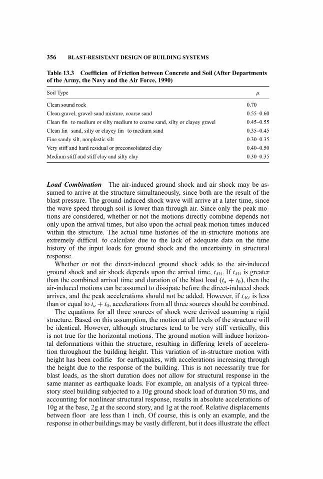
356 BLAST-RESISTANT DESIGN OF BUILDING SYSTEMS
Table 13.3 Coefficien of Friction between Concrete and Soil (After Departmentsof the Army, the Navy and the Air Force, 1990)
Soil Type µ
Clean sound rock 0.70Clean gravel, gravel-sand mixture, coarse sand 0.55–0.60Clean fin to medium or silty medium to coarse sand, silty or clayey gravel 0.45–0.55Clean fin sand, silty or clayey fin to medium sand 0.35–0.45Fine sandy silt, nonplastic silt 0.30–0.35Very stiff and hard residual or preconsolidated clay 0.40–0.50Medium stiff and stiff clay and silty clay 0.30–0.35
Load Combination The air-induced ground shock and air shock may be as-sumed to arrive at the structure simultaneously, since both are the result of theblast pressure. The ground-induced shock wave will arrive at a later time, sincethe wave speed through soil is lower than through air. Since only the peak mo-tions are considered, whether or not the motions directly combine depends notonly upon the arrival times, but also upon the actual peak motion times inducedwithin the structure. The actual time histories of the in-structure motions areextremely difficul to calculate due to the lack of adequate data on the timehistory of the input loads for ground shock and the uncertainty in structuralresponse.
Whether or not the direct-induced ground shock adds to the air-inducedground shock and air shock depends upon the arrival time, tAG. If tAG is greaterthan the combined arrival time and duration of the blast load (ta + t0), then theair-induced motions can be assumed to dissipate before the direct-induced shockarrives, and the peak accelerations should not be added. However, if tAG is lessthan or equal to ta + t0, accelerations from all three sources should be combined.
The equations for all three sources of shock were derived assuming a rigidstructure. Based on this assumption, the motion at all levels of the structure willbe identical. However, although structures tend to be very stiff vertically, thisis not true for the horizontal motions. The ground motion will induce horizon-tal deformations within the structure, resulting in differing levels of accelera-tion throughout the building height. This variation of in-structure motion withheight has been codifie for earthquakes, with accelerations increasing throughthe height due to the response of the building. This is not necessarily true forblast loads, as the short duration does not allow for structural response in thesame manner as earthquake loads. For example, an analysis of a typical three-story steel building subjected to a 10g ground shock load of duration 50 ms, andaccounting for nonlinear structural response, results in absolute accelerations of10g at the base, 2g at the second story, and 1g at the roof. Relative displacementsbetween floor are less than 1 inch. Of course, this is only an example, and theresponse in other buildings may be vastly different, but it does illustrate the effect
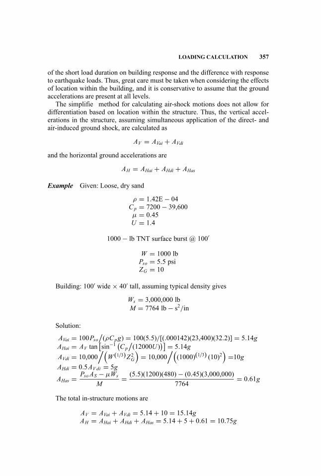
LOADING CALCULATION 357
of the short load duration on building response and the difference with responseto earthquake loads. Thus, great care must be taken when considering the effectsof location within the building, and it is conservative to assume that the groundaccelerations are present at all levels.
The simplifie method for calculating air-shock motions does not allow fordifferentiation based on location within the structure. Thus, the vertical accel-erations in the structure, assuming simultaneous application of the direct- andair-induced ground shock, are calculated as
AV = AVai + AVdi
and the horizontal ground accelerations are
AH = AHai + AHdi + AHas
Example Given: Loose, dry sand
ρ = 1.42E− 04Cp = 7200− 39,600µ = 0.45U = 1.4
1000− lb TNT surface burst @ 100′
W = 1000 lbPso = 5.5 psiZG = 10
Building: 100′ wide × 40′ tall, assuming typical density gives
Ws = 3,000,000 lbM = 7764 lb− s2/in
Solution:
AVai = 100Pso/(ρCpg) = 100(5.5)/[(.000142)(23,400)(32.2)] = 5.14g
AHai = AV tan[sin−1 (
Cp/(12000U )
)] = 5.14gAVdi = 10,000
/(W (1/3)Z2G
)= 10,000
/((1000)(1/3) (10)2
)=10g
AHdi = 0.5AVdi = 5g
AHas = Pso AS − µWs
M= (5.5)(1200)(480)− (0.45)(3,000,000)
7764= 0.61g
The total in-structure motions are
AV = AVai + AVdi = 5.14+ 10 = 15.14gAH = AHai + AHdi + AHas = 5.14+ 5+ 0.61 = 10.75g
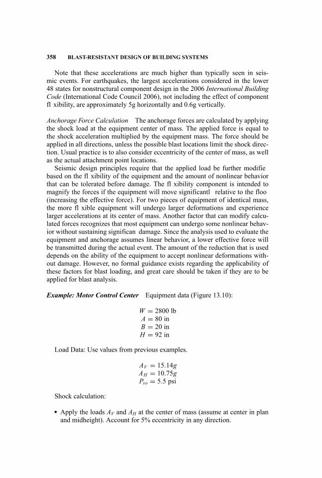
358 BLAST-RESISTANT DESIGN OF BUILDING SYSTEMS
Note that these accelerations are much higher than typically seen in seis-mic events. For earthquakes, the largest accelerations considered in the lower48 states for nonstructural component design in the 2006 International BuildingCode (International Code Council 2006), not including the effect of componentfl xibility, are approximately 5g horizontally and 0.6g vertically.
Anchorage Force Calculation The anchorage forces are calculated by applyingthe shock load at the equipment center of mass. The applied force is equal tothe shock acceleration multiplied by the equipment mass. The force should beapplied in all directions, unless the possible blast locations limit the shock direc-tion. Usual practice is to also consider eccentricity of the center of mass, as wellas the actual attachment point locations.
Seismic design principles require that the applied load be further modifiebased on the fl xibility of the equipment and the amount of nonlinear behaviorthat can be tolerated before damage. The fl xibility component is intended tomagnify the forces if the equipment will move significantl relative to the floo(increasing the effective force). For two pieces of equipment of identical mass,the more fl xible equipment will undergo larger deformations and experiencelarger accelerations at its center of mass. Another factor that can modify calcu-lated forces recognizes that most equipment can undergo some nonlinear behav-ior without sustaining significan damage. Since the analysis used to evaluate theequipment and anchorage assumes linear behavior, a lower effective force willbe transmitted during the actual event. The amount of the reduction that is useddepends on the ability of the equipment to accept nonlinear deformations with-out damage. However, no formal guidance exists regarding the applicability ofthese factors for blast loading, and great care should be taken if they are to beapplied for blast analysis.
Example: Motor Control Center Equipment data (Figure 13.10):
W = 2800 lbA = 80 inB = 20 inH = 92 in
Load Data: Use values from previous examples.
AV = 15.14gAH = 10.75gPso = 5.5 psi
Shock calculation:
� Apply the loads AV and AH at the center of mass (assume at center in planand midheight). Account for 5% eccentricity in any direction.
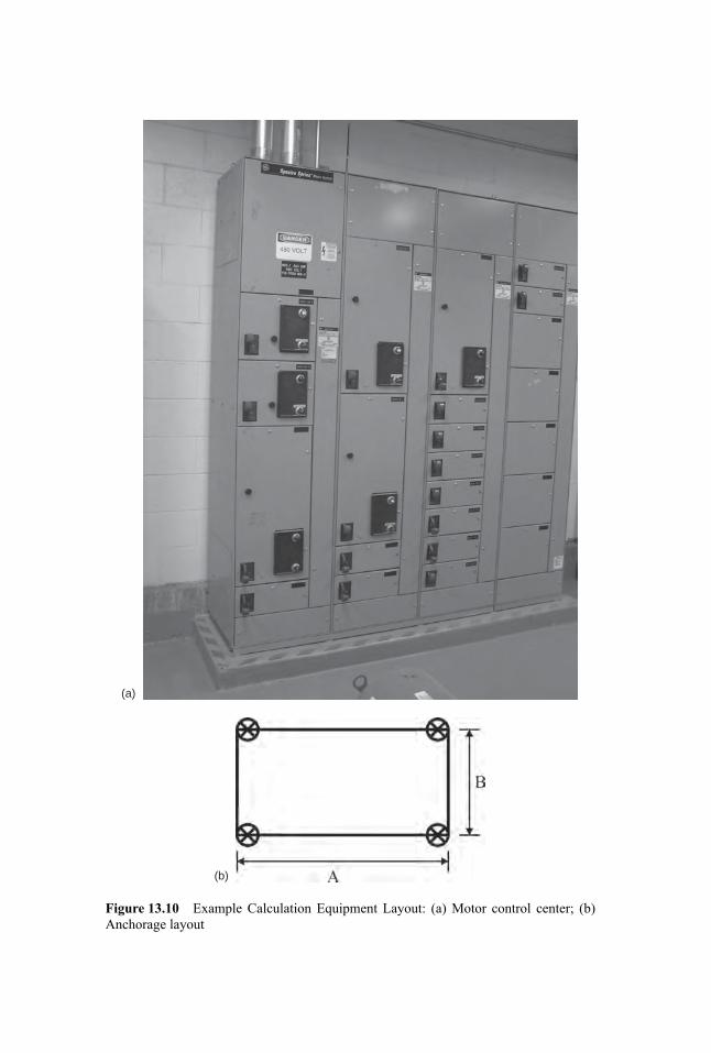
(a)
(b)
Figure 13.10 Example Calculation Equipment Layout: (a) Motor control center; (b)Anchorage layout

360 BLAST-RESISTANT DESIGN OF BUILDING SYSTEMS
� Calculate the anchorage forces assuming that static loads equal to AVW andAHW are applied simultaneously. The horizontal load can be applied in anydirection with the maximum anchorage forces governing.
The applied loads are:
Vertical = 15.14g ∗ 2800 lb = 42,392 lb (uplift or compression)Horizontal = 10.75g ∗ 2800 lb = 30,100 lb
The anchorage forces with the horizontal load applied in the short direction withzero eccentricity are:
Uplift = (42,392− 2800)/4+ (30,100)(46 in)/[2(20)] = 44, 513lbCompression = (42,392+ 2800)/4+ (30,100)(46 in)/[2(20)] = 45, 913lbHorizontal = 30,100/4 = 7525lb
and the resulting maximum anchorage forces considering eccentricity are:
Vertical = 47,632 lb upliftHorizontal = 8455 lb
Note that these are considerably higher than 1/4 of the applied loads due tothe location of the load application and the assumed eccentricities. In particular,the vertical forces are greatly increased due to the overturning moment imposedby the horizontal force.
These anchorage load values exceed the capacity of 11/4′ ′ anchors by approxi-
mately 25%. Adequate anchorage would require multiple anchors at each supportlocation. This compares to one 1/2′′ anchor required at each support location inan area of moderate seismic activity (UBC, Zone 3) (International Code Council1997).
Blast Calculation: Three basic approaches can be used to apply blast loads toequipment. First, the peak (or average) blast pressure can be applied as a staticforce. This is an extremely conservative approach for most equipment, as it ig-nores the short duration of the applied load. The second approach is to considerthe blast load to be impulsive in nature and to use a simplifie method to deter-mine the maximum response. A drawback to this approach is that the dynamiccharacteristics, mass and stiffness, of the equipment must be known, which isusually not the case. A third alternative is to explicitly calculate the time historyresponse of the equipment to the blast load, but this approach is rarely justifiedue to the—at best—approximate nature of the input parameters and the require-ment to know the equipment mass and stiffness distribution.
The firs two approaches will be considered in this example.Method 1 – Static Load Application
LOADING CALCULATION 361
� Apply the pressure as a static load distributed evenly across the exposedface.
� Calculate the anchorage forces for the given loads. The horizontal load canbe applied in any direction, but for symmetric equipment, applying the loadalong each principal axis is usually sufficient
The equivalent applied forces are:
Strong axis = 92 in ∗ 20 in ∗ 5.5 psi = 10,120 lbWeak axis = 92 in ∗ 80 in ∗ 5.5 psi = 40,480 lb
The resulting maximum anchorage forces are:
Strong axis loading vertical = 5119 lb (uplift)Strong axis loading horizontal = 2530 lb
Weak axis loading vertical = 185,508 lb (uplift)Weak axis loading horizontal = 10,120 lb
The anchorage forces generated by these loads are clearly beyond the capacityof a cost-efficien anchorage system. Several simplifying assumptions were madein this calculation. In addition to the static application of the load, no load wasapplied to the top, side, or rear surfaces. Loads applied on the top and rear facewill reduce the anchorage forces.
The exposed front face of the motor control center must be able to resist the5.5 psi load. The ability of most sheet metal to sustain such a load is doubtfulat best, with maximum duct pressures approaching 1 psi. Thus, although thisexample demonstrates the procedure for calculating the anchorage forces to aload of 5.5 psi, the equipment would have to be protected through barriers orrelocation to reduce the load to a level that could be resisted.
Method 2 – Impulsive LoadA typical natural frequency for lateral motion of a motor control center might
be 0.5 sec. For this example, that is a lateral stiffness of roughly 1000 lb/in. FromFigure 13.11 the dynamic amplificatio factor for a ratio of
t0T
= 0.0500.50
= 0.1
is D = 0.35. This leads to a maximum total horizontal reaction force of
Htotal = 0.35(5.5)(92)(20)0.35(5.5)(92)(80) = 3542 lbs
14,168 lbs
for the strong and weak directions, respectively. This calculation yields horizon-tal support loads of 885 and 3542 lbs, respectively. Similarly, the vertical forces
362 BLAST-RESISTANT DESIGN OF BUILDING SYSTEMS
Figure 13.11 Dynamic Amplificatio Factor for Triangular Impulse Loads
due to blast are D times the static values. This results in
V = 2246 lbs65,382 lbs
The vertical loads (uplift) are still very large, but are likely able to be resistedwith proper anchor design, certainly if direct attachment to steel is possible.
Stiffer equipment (smaller T) will have larger dynamic amplificatio factors,while more fl xible equipment will see greater reductions in force.
13.5 SUMMARY
Presently, there is little guidance and few standards for blast-resistant design ofbuilding systems for civilian structures. Although there are several efforts cur-rently under way, familiarity and selective adoption of methods used in otherarenas, such as used by the DoD in hardening combatant-type systems, can beeconomically and practically exported to the civilian building theater. Likewise,adoption of new and available technologies, such as LED lighting, can providereasonable stopgap measures.
This chapter has attempted to highlight the main areas of concern, providebasic guidance as to the issues to be addressed, and demonstrate computationaltechniques where appropriate. However, given the lack of recognized, standard-ized design procedure, it is imperative to recognize that, as in all engineering,there is no substitute for common sense and engineering judgment. The

REFERENCES 363
principles of design remain unchanged, despite the lack of exact knowledgeregarding the loading and capacity for resistance.
REFERENCES
American Society of Heating, Refrigerating and Air-Conditioning Engineers. 2007.ASHRAE Handbook: Applications. Atlanta, GA: American Society of Heating, Re-frigerating and Air-Conditioning Engineers.
Departments of the Army, the Navy and the Air Force. 1990. Structures to Resist theEffects of Accidental Explosions, rev. 1 (Department of the Army TM 5-1300, De-partment of the Navy NAVFAC P-397, Department of the Air Force AFM 88-22).Washington, DC: Departments of the Army, the Navy and the Air Force.
International Code Council. 1997. Uniform Building Code. Washington, DC: Interna-tional Code Council.
. 2006. International Building Code. Washington, DC: International CodeCouncil.
National Fire Protection Association. 2005. National Electrical Code Requirements forOne- and Two-Family Dwellings (NFPA 70A). Quincy, MA: National Fire ProtectionAssociation.
U.S. Department of the Army. 1986. Fundamentals of Protective Design for Conven-tional Weapons (TM 5-855-1). Washington, DC: U.S. Department of the Army.

IV Blast-Resistant Detailing
Handbook for Blast-Resistant Design of Buildings Edited by Donald 0. Dusenberry
Copyright 0 2010 by John Wiley & Sons, Inc. All rights reserved.

14 Blast-Resistant DesignConcepts and MemberDetailing: Concrete
Steven Smith and W. Gene Corley
The next four chapters provide design and detailing guidelines for membersconstructed from reinforced concrete, steel, and masonry, as well as membersstrengthened using fibe -reinforced polymers (FRP).
The general approach for all of these materials systems is to use two indepen-dent approaches to providing the toughness that is critical to blast resistance. Theapproaches are informally associated with strength and ductility (which, takentogether, provide toughness). Strength is scaled through the response limits foreach level of protection (LOP). For example, the response limit targets for LOPIV are elastic response. Thus, members designed to this LOP will be larger andstronger than those designed to lower LOP (which allow greater displacement).However, recognizing the universal need for ductility, the detailing recommenda-tions are often constant for all LOP. For the lower LOP, this provides the ductilitynecessary to achieve the expected response limits. For higher LOP, this detail-ing provides a higher margin against the uncertainties inherent to blast-resistantdesign.
14.1 GENERAL
14.1.1 Scope
Detailing recommendations for reinforced concrete structures are provided inthis chapter. The nature of high-rise structures in a dense urban environmentintroduces significan complexity, including near-fiel blast loads and intricatestructural members such as transfer girders. For this reason, the methods pre-sented in this section, while generic in nature, are best applied to low-rise struc-tures with moderate standoff distance (say, Z > 3.0).
The seismic provisions in ACI 318-08, Building Code Requirements for Struc-tural Concrete (American Concrete Institute 2008), provide the basis for the de-tailing, although many references are also made to UFC 3-340-02, Structures
367
Handbook for Blast-Resistant Design of Buildings Edited by Donald 0. Dusenberry
Copyright 0 2010 by John Wiley & Sons, Inc. All rights reserved.
368 DESIGN CONCEPTS AND MEMBER DETAILING: CONCRETE
to Resist the Effects of Accidental Explosions (Unifie Facilities Criteria 2008).Chapter 21 of ACI 318-08 contains requirements for design and construction ofstructures subjected to earthquake motions. The requirements are scaled to theseverity of earthquake motions and are identifie as ordinary, intermediate, andspecial moment frames. Special moment frame (SMF) requirements provide thehighest level of performance and are the primary resource for the ACI provisionsreferenced in this chapter.
The general intent of seismic detailing is to provide greater ductility andpost-yield strength than conventional detailing. This is consistent with the blast-resistant design intent of improving toughness. The Portland Cement Associa-tion’s Blast Resistant Design Guide for Reinforced Concrete Structures (PortlandCement Association 2009) contains additional discussion of structural aspects ofseismic and blast phenomena, as do Hayes (Hayes et al. 2005) and Bilow (Bilowand Kamara 2007).
14.2 FAILURE MODES
14.2.1 Flexural
Flexure is in many instances intended to be the primary structural mode for mem-bers resisting blast loads. This is due to two related concepts: the relatively pre-dictable nature of, and the ductility associated with, fl xural response.
Columns subjected directly to lateral air-blast pressures are often the singlemost critical design consideration for blast-resistant design. Columns directlyexposed to blast pressures will respond primarily in fl xure. In fact, UFC3-340-02 recommends disregarding the column axial load and analyzing itsolely as a beam. Neglecting the compressive preload is generally a conservativeapproach to sizing columns, as long as a separate stability check is performedthat includes the axial load.
Columns may develop a three-hinged mechanism with plastic hinge zoneslocated at end supports and at an intermediate point along the length of the col-umn. The location of the intermediate plastic hinge can be determined by anal-ysis and depends on the location of the blast source as well as the height andproperties of the column. However, this analysis can be complex and may re-quire assumptions that render results of little use. For most situations, the bestapproach is either to conservatively design the column for the potential of a hingeanywhere along the entire length, or to make general assumptions of intermedi-ate hinge location based on the anticipated blast loading. If the column is inthe far field the blast pressure will be essentially uniform, and the intermediatehinge will form near the center of the column (assuming no other structural de-tails that would alter the symmetry of the column response). If the column is inthe near field and subjected to blast from a package bomb, the blast pressureswill be concentrated at the base of the column, and move the intermediate hingedownward.
FAILURE MODES 369
Seismic design philosophy as applied in FEMA 350, Recommended SeismicDesign Criteria for New Steel Moment-Frame Buildings (Federal EmergencyManagement Agency 2000) employs a target hinge rotation of 0.03 rad (approx-imately 2◦). This hinge rotation can also be associated with reinforced concretedesign (Bilow and Kamara 2007). Potential hinge rotations under blast loading,however, span a wide range. as described elsewhere in this handbook. Thetarget seismic deformation magnitude, and overall response intent, would bebest associated LOP II–III. The extreme deformations, structural damage, andallowance of tension membrane associated with LOP I are beyond the intent ofseismic design.
14.2.2 Diagonal Tension
Diagonal tension shear is a brittle failure mode and must be avoided. Caremust be taken to provide sufficien shear capacity to allow for the full fl x-ural development of the section. The phi-factors provided in ACI 318-08 areintended to promote preferential failure modes; a greater strength reduction isapplied to shear than fl xure. However, the structural analyst has the task ofobtaining the correct member reactions, particularly when conducting single-degree-of-freedom (SDOF) analysis and mapping the results back to the physicalsystem.
14.2.3 Direct Shear
The primary focus of blast analysis is typically the dynamic fl xural response ofmembers. However, earlier during the blast event, direct shear forces are trans-mitted to the element supports. The magnitude of the direct shear force may besignificantl greater than the reaction due to dynamic fl xural response, thoughthe resistance to direct shear is also typically greater that diagonal shear resis-tance.
Direct shear can be an even more brittle mode of response than diagonal ten-sion. Direct shear is the phenomenon of failure at a shear plane, typically at theface of a support. Direct shear is resisted by shear friction and inclined reinforce-ment. Specifi detailing guidelines for beams and columns are provided later inthis chapter.
14.2.4 Membrane
Slabs and beams that develop extreme deformations from large, directly appliedblast loading may be designed to transition from a fl xural response to a tensionmembrane response. In addition to careful detailing of the slab or beam, thismode of response requires careful consideration of the large in-plane forces thatwill be transmitted to the surrounding structural elements.
370 DESIGN CONCEPTS AND MEMBER DETAILING: CONCRETE
14.2.5 Stability
Stability is a critical design factor for columns. Designing the column to supportsome or even the entire design load after loss of intermediate lateral support isan indirect means of providing substantial buckling resistance. This equates toa scenario of the loss of bracing from floo framing, and essentially requiresdesigning the column for an unbraced length equal to two story heights.
This is not a blast-resistant design method per se, although it clearly relatesto the way the building will resist progressive collapse. However, this is suchan important design consideration that it should be carefully considered, even ifformal progressive collapse design is not utilized. And, this is an essential designconcept whenever a strong-column, weak-beam approach is used.
14.3 DETAILING
14.3.1 General
General procedures that will promote toughness include:
1. Use of concrete with a minimum strength greater than 3,000 psi. This willhelp to ensure against brittle shear failure.
2. Concrete with strength greater than 10,000 psi should be used with cautiondue to its potentially brittle failure mode in fl xure.
3. All concrete should be normal weight. Existing test data and analysis of theresponse of reinforced concrete to blast and seismic loading are primarilybased on normal-weight concrete. Thus, for normal-weight concrete, con-cepts such as strain-rate effects, fragmentation, and pressure-impulse (P-I)calibration for deformation limits are best understood.
4. The ACI 318-08 design compressive strain in concrete of 0.003 should alsobe applied to blast-resistant design, to avoid crushing of concrete and anassociated brittle failure in fl xure.
5. Reinforcing bars are recommended to be ASTM A706 (ASTM 2006).Where ASTM A615 (ASTM 2008) bars are used, limitations as specifiein ACI 318-08, Section 21.2.5, should be applied. The primary concernsfor reinforcing steel are the ratio of yield to ultimate strength and the ac-tual yield versus design yield strength. A large ratio of yield to ultimatestrength is necessary to provide sufficien ductility and energy absorption.Tests indicate that reinforcing that has actual tensile strength exceedingthe actual yield strength by at least 25% provides substantial yield region.Additionally, the actual yield strength should not exceed the design yieldstrength by more than 18,000 psi. The intent of this limitation is to preventthe development of undesirable failure modes (such as shear) prior to theformation of plastic hinges.
6. Reinforcing bar sizes should be smaller than No. 11.

DETAILING 371
7. Straight reinforcing bars should be used to avoid reduced ductility at bends.8. Continuity with In-plane Members: Every opportunity should be taken to
provide a load path from framing members to plane elements. For example,beams should be tied to floo slabs, and columns to bearing walls. Partic-ularly in situations when blast forces would be directed against the weakaxis of the member (often the case for beams), this approach can providethe required blast resistance without having to substantially increase thedimensions of the member.
9. Balanced Design: Where appropriate, members should be designed to re-sist the full capacity of supported elements (as define by a governingfailure mechanism), rather than the design loads transmitted by those el-ements. For example, it may be desirable for a girder supporting a flooslab to be designed to resist in-plane forces developed by catenary actionin the slab, even though these forces might be significantl greater thanforces developed from the design loads alone with the slab responding in afl xural mode.
10. Weak-Beam, Strong-Column: Beam failure is generally preferable to col-umn failure, since the beam failure typically only affects the structure inclose proximity, whereas the column failure could lead to progressive col-lapse.
11. ACI 318-08 includes provisions for spiral reinforcement (referred to as“laced” in UFC 3-340-02). Spiral reinforcement provides confinemen andtorsion and shear capacity that are superior to stirrups and rectangular hoopreinforcement. References to selected ACI 318-08 guidelines for spiral re-inforcement are included below. UFC 3-340-02 includes more detailedinformation on detailing members with laced reinforcement. In general,the higher performance of spiral reinforcement is most necessary for veryclose-in blasts (Z < 1.0), which are beyond the scope of this guide. Butany situation requiring a high level of structural performance merits con-sideration of spiral reinforcement.
14.3.2 Splices
Splicing can be achieved by lapping bars (No. 11 bars and smaller), mechanicalconnectors, or welding. It is good practice to locate splices in noncritical regions,where low stress states are expected under blast conditions. In particular, splicesshould be avoided in locations where plastic hinges are likely to form and atmember intersections. The percentage of bars spliced in a single location shouldbe limited to 25 percent if possible. Splices should also be separated along theaxial length of a member by at least twice the member depth (Figure 14.1).
Lap splices should satisfy ACI 318-08 Class B requirements, which providefor a 30% increase in development length over Class A lap splices. Lap splicesshould be enclosed by lateral reinforcement conforming to Sections 21.6.4.2,21.6.4.3, and 21.6.4.5 of ACI 318-08, to provide adequate confinemen of the
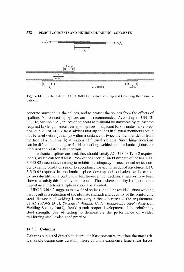
372 DESIGN CONCEPTS AND MEMBER DETAILING: CONCRETE
Abfy
1.3 ld
1.3 ld
1.3 ld
1.3 ld
1.3 ld2 d (min)
(min)
Abfy
Figure 14.1 Schematic of ACI 318-08 Lap Splice Spacing and Grouping Recommen-dations.
concrete surrounding the splices, and to protect the splices from the effects ofspalling. Noncontact lap splices are not recommended. According to UFC 3-340-02, Section 4-21, splices of adjacent bars should be staggered by at least therequired lap length, since overlap of splices of adjacent bars is undesirable. Sec-tion 21.5.2.3 of ACI 318-08 advises that lap splices in fl xural members shouldnot be used within joints (a) within a distance of twice the member depth fromthe face of a joint, or (b) at regions of fl xural yielding. Since hinge locationscan be difficul to anticipate for blast loading, welded and mechanical joints arepreferred for blast-resistant design.
If mechanical splices are used, they should satisfy ACI 318-08 Type 2 require-ments, which call for at least 125% of the specifie yield strength of the bar. UFC3-340-02 necessitates testing to exhibit the adequacy of mechanical splices un-der dynamic conditions prior to acceptance for use in hardened structures. UFC3-340-02 requires that mechanical splices develop both equivalent tensile capac-ity and ductility of a continuous bar; however, no mechanical splices have beenshown to satisfy this ductility requirement. Thus, where ductility is of paramountimportance, mechanical splices should be avoided.
UFC 3-340-02 suggests that welded splices should be avoided, since weldingmay result in a reduction of the ultimate strength and ductility of the reinforcingsteel. However, if welding is necessary, strict adherence to the requirementsof ANSI/AWS D1.4, Structural Welding Code—Reinforcing Steel (AmericanWelding Society 2005), should permit proper development of the reinforcingsteel strength. Use of testing to demonstrate the performance of weldedreinforcing steel is also good practice.
14.3.3 Columns
Columns subjected directly to lateral air-blast pressures are often the most crit-ical single design consideration. These columns experience large shear forces,
DETAILING 373
out-of-plane deformations that can lead to instability, and reflecte pressures thatmay have the potential to shatter concrete.
The fl xural response of the columns may develop a three-hinged mechanismwith plastic hinge zones located at end supports and at an intermediate pointalong the length of the column. The location of the intermediate plastic hingecan be determined by analysis and depends on the location of the blast source aswell as the height and properties of the column. This analysis can be challenging,and may require assumptions that render results of little use. For most situations,the best approach is either to conservatively design the column for the potentialof a hinge anywhere along the entire length, or to make general assumptions ofintermediate hinge location based on the anticipated blast loading. If the columnis in the far field the blast pressure will be essentially uniform, and the interme-diate hinge will form near the center of the column (assuming no other structuraldetails that would alter the symmetry of the column response). If the column isin the near field and subjected to blast from a package bomb, the blast pressureswill be concentrated at the base of the column, and move the intermediate hingedownward.
The P-Delta moment generated by the inelastic response must be addressed.Of critical concern is whether the column can develop inelastic response andmaintain sufficien moment capacity to resist the associated P-Delta effect.FEMA-350, Recommended Seismic Design Criteria for New Steel Moment-Frame Buildings (Federal Emergency Management Agency 2000), addressesthis concern for structural steel seismic special moment frames by requiringthe moment capacity at 0.03 radians of inelastic response to be greater thanthe nominal plastic moment, Mp. A similar rationale can be adopted for re-inforced concrete members, and a synthesis study of available reinforced con-crete SMF data indicates that this detailing provides inelastic response of 0.03radians at the connections. This level of response would equate to the Mod-erate to Heavy criteria which are typically associated with LOP III and II,respectively.
Detailing of beam-column joints is discussed in Section 14.3.5 of this chapter,and per the above discussion it is an essential component of achieving P-Deltaresistance by providing lateral restraint at frame points.
P-Delta resistance within the clear height of the column is achieved withproper reinforcement detailing so that inelastic response in this region does notunacceptably reduce the fl xural resistance of the column. Detailing for columnsshould be based on SMF provisions in ACI 318-08, Section 21.6. The followingsubsections present the primary issues to address.
Longitudinal Reinforcement Section 21.6.3.1 of ACI 318-08 limits the area oflongitudinal reinforcement to between 1% and 6% of the gross area. The lowerlimit provides that the column will achieve the yield moment before the crackingmoment. The upper limit addresses congestion and avoiding development of highshear stresses. To minimize the number of iterations, it is typically best to beginthe design process with reinforcing steel at the 6% limit.
374 DESIGN CONCEPTS AND MEMBER DETAILING: CONCRETE
Transverse Reinforcement (Diagonal Shear and Confinement Transverse re-inforcement serves the equally important purposes of resisting diagonal tensionand providing confinement Confinemen from closely spaced hoops protects thecore concrete from being shattered by high, directly applied blast pressures, orcrushed by large deflection and stresses at locations of large inelastic fl xuralresponse. Maintaining the integrity of the core concrete is critical for lateral re-straint of the longitudinal reinforcement and allows the concrete to contributeto the shear capacity of the section. Hoops and ties for confinemen are par-ticularly critical in regions of inelastic response. Per the previous discussion ofintermediate hinge location, unless that position can be reliably predicted, it isrecommended that transverse reinforcement be provided per Section 21.6.4 ofACI 318-08 over the clear height of the column, rather than only over a distancel0, as define in Section 21.6.4.1. Where steel jacketing is provided, transversereinforcement can be reduced, since the steel jacket will protect against spallingand provide the necessary confinement
Transverse reinforcement spaced to satisfy confinemen requirements (Sec-tion 21.6.4) will likely satisfy shear requirements for diagonal tension; however,the requirements of Section 11.4 should always be checked, particularly whenthe confinemen requirements of Section 21.6.4 are not provided over the clearheight of the column.
Direct Shear Columns must be designed to resist the effects of direct shear aswell as fl xure and diagonal tension, although in most cases the direct shear willnot control.
Resistance to direct shear from blast loading can be treated in a manner similarto that of Section 11.6 of ACI 318-08, which provides minimum requirements forshear friction reinforcement. The shear friction concept presumes a crack at thecritical shear plane, such that sufficien reinforcing steel is required to maintaininterlock of the rough, mating surfaces. Since the function of the shear frictionreinforcement is to resist the tendency of the shear plane to open, it is the tensilecapacity (not shear) that is of interest; as long as there is sufficien steel, andit does not yield, the mating surfaces will remain engaged and resist the shear.Presuming sufficien shear friction reinforcement (as define ACI 319, Section11.6), the direct shear capacity of the concrete and any inclined bars that crossthe shear plane can be calculated as
Vn = 0.18 f′cdbd + As fyd cosα
Where, f ′cd is the product of the concrete compressive strength, DIF and SIF; As
is the area of inclined steel bars; fyd is the product of the steel yield stress, DIFand SIF; and α is the angle formed by the plane of the inclined reinforcement andthe surface of the shear plane. Note also that since the direct shear phenomenonoccurs very early during the blast application, and before the development offl xural response, Type I cross section is used. Type I cross section is define asthe uncracked cross section; that is, the complete concrete cross section can becounted for resisting the direct shear.
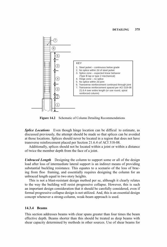
DETAILING 375
6
7
5
3
4
3
2
KEY
1. Steel jacket – continuous below grade2. No splice within 2d of steel jacket 3. Splice zone – expected linear behavior (Type B lap or type 2 mechanical) 4. Hinge zone – no splice5. No splice within 2d joint6. Transverse reinforcement continued through joint7. Transverse reinforcement spaced per ACI 318-08 21.6.4 over entire length (or use round, spiral reinforced column)
1
Figure 14.2 Schematic of Column Detailing Recommendations
Splice Locations Even though hinge location can be difficul to estimate, asdiscussed previously, the attempt should be made so that splices can be avoidedat those locations. Splices should never be located in a region that does not havetransverse reinforcement placed per Section 21.6.4 of ACI 318-08.
Additionally, splices should not be located within a joint or within a distanceof twice the member depth from the face of a joint.
Unbraced Length Designing the column to support some or all of the designload after loss of intermediate lateral support is an indirect means of providingsubstantial buckling resistance. This equates to a scenario of the loss of brac-ing from floo framing, and essentially requires designing the column for anunbraced length equal to two story heights.
This is not a blast-resistant design method per se, although it clearly relatesto the way the building will resist progressive collapse. However, this is suchan important design consideration that it should be carefully considered, even ifformal progressive collapse design is not utilized. And, this is an essential designconcept whenever a strong-column, weak-beam approach is used.
14.3.4 Beams
This section addresses beams with clear spans greater than four times the beameffective depth. Beams shorter than this should be treated as deep beams withshear capacity determined by methods in other sources. Use of shear beams for

376 DESIGN CONCEPTS AND MEMBER DETAILING: CONCRETE
blast-resistant design should be carefully considered due to the potentially brittlefailure modes associated with them.
Exterior beams subjected directly to lateral air-blast pressures experiencelarge shear forces, out-of-plane deformations that can lead to the developmentof plastic hinges, and reflecte pressures that may have the potential to shatterconcrete. Interior beams may be subjected to either direct blast pressures in theform of uplift (for situations in which the interior of the building becomes pres-surized) and forces transmitted from other structural members.
Plastic hinge development for exterior beams is similar to that for columns,as previously discussed. Plastic hinge zones can develop at fi ed supports and atintermediate points along the length of a beam. The exact location of an inter-mediate plastic hinge can be determined by analysis and depends on the locationof the blast source as well as the span and properties of the column. In lieu ofsuch complex analysis, two general cases can be considered to bound the prob-lem. Beams subjected to far-fiel blast load will most likely develop hinges atsupports and at midspan. This assumes that the load applied to the beam froma far-fiel blast will be nearly uniform over the column length. Sources of ex-ceptions to this assumption could include very long span beams and beams withintermediate framing. Beams subjected to near-fiel blast load will most likelydevelop the middle plastic hinge at a location biased to the position of the blastsource.
Simply supported beams can be used in blast-resistant structures if they can beshown to satisfy the required level of performance. However, the designer mustbe aware that the simple supports limit the available potential energy dissipationand additional margin against unanticipated blast effects.
Detailing for beams should be based on SMF provisions in ACI 318-08, Sec-tion 21.5. The following subsections present primary issues to address during thedesign process.
Longitudinal Reinforcement Longitudinal reinforcement should comply withACI 318-08, Sections 21.5.2.1 and 21.5.2.2. Beams subjected to uplift shouldhave reinforcement designed to resist both the uplift and rebound.
Transverse Reinforcement (Diagonal Shear and Confinement Transverse re-inforcement serves the equally important purposes of resisting diagonal tensionand providing confinement Confinemen from closely spaced hoops protects thecore concrete from being shattered by high, directly applied blast pressures, orcrushed by large deflection and stresses at locations of large inelastic fl xuralresponse. Maintaining the integrity of the core concrete is critical for lateral re-straint of the longitudinal reinforcement, and allows the concrete to contributeto the shear capacity of the section. Hoops and ties for confinemen are particu-larly critical in regions of inelastic response. Transverse reinforcement should bespaced to satisfy 21.5.3.2 and provided over the clear span of the beam, unlessspecifi analysis of yield zone location supports alternate placement. Transversereinforcement spaced to satisfy 21.5.3.2 will likely satisfy shear requirements
DETAILING 377
for diagonal tension; however, the requirements of Section 11.4 should alwaysbe checked, particularly when the confinemen requirements of Section 21.5.3.2are not provided over the clear span of the column.
Single-piece hoops as shown in Detail A of Figure R21.5.3 of ACI 318-08 arepreferred to hoops built up from multiple members.
Direct Shear The discussion and recommendations for direct shear in columnscan be directly applied to beams.
Splice Location Even though hinge location can be difficul to estimate, asdiscussed previously, the attempt should be made so that splices can be avoidedat those locations. Splices should never be located in a region that does not havetransverse reinforcement placed per Section 21.5.4 of ACI 318-08.
14.3.5 Beam-Column Joints
Joint design is critical to providing an engineered response to blast loading. Thedevelopment of inelastic response, which typically accounts for the majority ofenergy dissipation for LOP I–III, is directly related to connection performance.The performance intent of LOP IV is essentially elastic response to the designblast load; achieving this intent, and also providing margins against unanticipatedload magnitudes, requires equally careful joint detailing.
The performance expectations of the various levels of protection can poten-tially be achieved with a simple joint between beams and columns, but the trade-off of this design approach is potentially massive beams.
The monolithic nature of reinforced concrete can be used to great advantage inthe development of robust beam-column joints. Reinforced concrete joints inher-ently provide substantial deformation continuity between beams and columns.To provide the level of performance demanded for blast resistance, measuresmust be taken to ensure ductility and to protect the core concrete. These goalsare primarily achieved through detailing considerations for the beam longitudi-nal reinforcement (ductility) and column transverse, confinemen reinforcement(protection of core concrete).
Longitudinal Reinforcement Wherever possible, beam longitudinal reinforce-ment should be continuous through joints. Splices should not occur within joints,or within a distance of twice the beam depth from the face of the joint.
Reinforcement that terminates at a joint should comply with Section 21.7.2.2,which requires the reinforcement to be anchored at the far face of the confinecolumn core.
Transverse Reinforcement Column transverse reinforcement should be con-tinued through the joint, as described in Section 21.7.3. This section providesconsideration of the similar function that is provided by continuous beam lon-gitudinal reinforcement for joints that have beams framed to all four faces. The
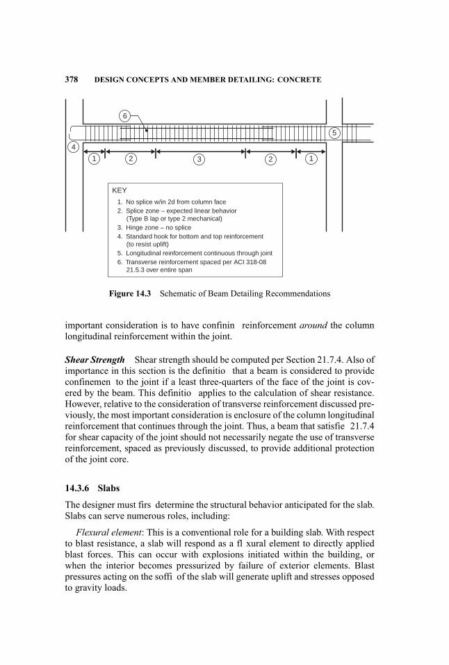
378 DESIGN CONCEPTS AND MEMBER DETAILING: CONCRETE
4
1 2
6
3 2 1
5
KEY
1. No splice w/in 2d from column face
3. Hinge zone – no splice4. Standard hook for bottom and top reinforcement (to resist uplift)5. Longitudinal reinforcement continuous through joint6. Transverse reinforcement spaced per ACI 318-08 21.5.3 over entire span
2. Splice zone – expected linear behavior (Type B lap or type 2 mechanical)
Figure 14.3 Schematic of Beam Detailing Recommendations
important consideration is to have confinin reinforcement around the columnlongitudinal reinforcement within the joint.
Shear Strength Shear strength should be computed per Section 21.7.4. Also ofimportance in this section is the definitio that a beam is considered to provideconfinemen to the joint if a least three-quarters of the face of the joint is cov-ered by the beam. This definitio applies to the calculation of shear resistance.However, relative to the consideration of transverse reinforcement discussed pre-viously, the most important consideration is enclosure of the column longitudinalreinforcement that continues through the joint. Thus, a beam that satisfie 21.7.4for shear capacity of the joint should not necessarily negate the use of transversereinforcement, spaced as previously discussed, to provide additional protectionof the joint core.
14.3.6 Slabs
The designer must firs determine the structural behavior anticipated for the slab.Slabs can serve numerous roles, including:
Flexural element: This is a conventional role for a building slab. With respectto blast resistance, a slab will respond as a fl xural element to directly appliedblast forces. This can occur with explosions initiated within the building, orwhen the interior becomes pressurized by failure of exterior elements. Blastpressures acting on the soffi of the slab will generate uplift and stresses opposedto gravity loads.
DETAILING 379
Diaphragm: Slabs that are intended to act as diaphragms for lateral responseto conventional loads can also be used to efficientl distribute blast forcesthrough the structure, and thus dissipate the blast effects by engaging additionalstructural elements and building mass.Local Restraint: Slabs that are not explicitly intended to perform as a di-
aphragm can still be used to provide local lateral restraint to beams that aredirectly exposed to transverse blast forces. This can be a very effective way tosupport beams against the weak-axis bending.Membrane: Slabs that develop extreme deformations from large, directly ap-
plied blast loading may be designed to transition from a fl xural response toa tension membrane response. In addition to careful detailing of the slab, thismode of response requires careful consideration of the large in-plane forces theslab will transmit to the surrounding structural elements.
The following subsections are concerned with slab-detailing considerations.
Flexural Reinforcement The fl xural reinforcement ratio should not be lessthan 0.0018. This is the limit for temperature and shrinkage, when using 60 ksireinforcement, given in Section 7.12. In practice, the reinforcement ratio willalmost always exceed this.
Flexural reinforcement should be provided at top and bottom throughout theslab. For blast scenarios in which uplift is expected, the top reinforcement shouldbe explicitly designed to resist the uplift forces, and the bottom reinforcement toresist rebound. In the event that design blast loads will not subject the slab touplift, but the slab is part of the structural system that will resist blast effects,it is good practice to provide approximately equal amounts of top and bottomreinforcement. This approach will provide reserve capacity for events such as anunanticipated reversal of curvature or loss of a support.
Bottom reinforcement should be continuous across interior supports. This isparticularly important in the column strip of two-way flat-sla floo systems.At exterior supports, the reinforcement should be fully developed. This bottomreinforcement detailing is a precaution against the loss of a support, providingthe structural potential for the slab to bridge across the lost support.
Connected Elements Structural elements connected to a slab should generallybe designed to establish the full capacity of the slab (i.e., balanced design). Thismust be carefully considered where the slab is intended to develop tension mem-brane behavior, because the in-plane forces that will need to be equilibrated bythe surrounding structure will be many times larger than the fl xural forces trans-ferred from the slab.
Slabs that serve as lateral restraint for beams directly subjected to blast pres-sures must have sufficien connectivity for the beam to engage the mass andin-plane stiffness of the slab.
Fully distributed force transfer between the slab and connected elements isthe preferred mechanism for all situations. For structures with concrete framingmembers, this is readily achieved. With steel-framed structures, the best method
380 DESIGN CONCEPTS AND MEMBER DETAILING: CONCRETE
is to cast the member into the concrete slab. For example, for a steel girder sup-porting a concrete deck, the top flang of the girder should be cast into the deck,if possible, rather than using shear studs.
14.3.7 Walls
As with slabs, the designer must firs determine the structural behavior antici-pated for the wall. Walls can serve numerous roles, including:
Gravity System: As part of the gravity load system, walls may experienceuplift from internal pressurization, or, in rare instances, increased compressiveloads from internal overpressures at higher floorsFlexural Element: A wall will have to be able to respond in fl xure in the event
of blast forces applied directly to one face, or unbalanced blast forces applied toboth faces. This can occur with explosions that are set off within a building, or ifthe interior becomes pressurized from failure of exterior elements.Diaphragm: Walls that are intended to act as diaphragms for lateral response
to conventional loads can also be used to efficientl distribute blast forcesthrough the structure, and thus dissipate the blast effects by engaging additionalstructural elements and building mass.Local Restraint: Walls that are not explicitly intended to perform as a di-
aphragm can still be used to provide local lateral restraint to columns that aredirectly exposed to transverse blast forces.
The following subsections are concerned with wall-detailing considerations.
Reinforcement The minimum web reinforcement ratio should be 0.0025,which will satisfy requirements for both in- and out-of-plane loads. Reinforce-ment should be placed in at least two curtains and fully developed at the wallboundaries. Section 21.9 of ACI 318-08, “Special Structural Walls,” containsadditional useful design recommendations and commentary.
Connected Elements Walls that may be subjected directly to transverse blastpressure and that also provide gravity support for elements in higher storiesshould be constructed with columns at each end and a beam spanning betweenthe columns. The purpose of this is to provide a gravity load path in the eventthat the wall is compromised by the transverse blast load. The beams, columns,and joints should be designed per previous sections of this chapter.
REFERENCES
This chapter is adapted in large part from information in the PCA’s Blast Resistant DesignGuide for Reinforced Concrete Structures (Portland Cement Association 2009), withthe permission of the Portland Cement Association.American Concrete Institute. 2008. Building Code Requirements for Structural Concrete(ACI 318-08) and Commentary (ACI 318R-08). Farmington Hills, MI: AmericanConcrete Institute.

REFERENCES 381
American Welding Society. 2005. Structural Welding Code—Reinforcing Steel(ANSI/AWS D1.4). Miami, FL: American Welding Society.
ASTM. 2006. Specificatio for Low-Alloy Steel Deformed Bars for Concrete Reinforce-ment (A706). West Conshohocken, PA: ASTM International.
. 2008. Specificatio for Deformed and Plain Billet-Steel Bars for Concrete Re-inforcement (A615). West Conshohocken, PA: ASTM International.
Bilow, D. and M. Kamara. 2007. Capacity of joints to resist impact loads in concretemoment-resisting frame buildings. Presented at the Structural Engineering InstituteStructural Congress, Long Beach, CA, May 16–19, 2007.
Departments of the Army, the Navy and the Air Force (DOANAF). 1990. Structures toResist the Effects of Accidental Explosions (Department of the Army Technical ManualTM 5-1300). Washington, DC: Departments of the Army, the Navy and the Air Force.
Federal Emergency Management Agency. 2000. Recommended Seismic Design Crite-ria for New Steel Moment-Frame Buildings (FEMA 350). Washington, DC: FederalEmergency Management Agency, Department of Homeland Security.
Hayes, J. et al. 2005. Can strengthening for earthquake improve blast and progressivecollapse resistance? Journal of Structural Engineering 131 (8): 1157–1177.
Portland Cement Association. 2009. Blast Resistant Design Guide for Reinforced Con-crete Structures. Skokie, IL: Portland Cement Association.
Unifie Facilities Criteria Program. 2008. Structures to Resist the Effects of AccidentalExplosions (UFC 3-340-02). Washington, DC: U.S. Department of Defense, UnifieFacilities Criteria Program.
15 Blast-Resistant Design Conceptsand Member Detailing: Steel
Charles Carter
15.1 GENERAL
This chapter provides guidance on the design of steel structures for blast loads.It is adapted from information in two references: “Defensive Design” (Shipeand Carter 2003) and Defensive Design of Structural Steel Buildings (Gilsanzet al. 2009), with the permission of the American Institute of Steel Construction(AISC).
Considerations for defensive design usually fall into one of three generalcategories: typical building designs, prescriptive building designs, andperformance-based building designs. Some designs combine prescriptive andperformance-based approaches.
15.1.1 Typical Building Designs
The majority of buildings receive no special treatment other than judicious atten-tion to redundant configuration and robust connection designs so that the struc-tural (and nonstructural) components are tied together effectively. The typicaldetails used in steel buildings inherently provide for redundancy and robustness,with the capability for load redistribution through alternative load paths. Thisfact has been demonstrated repeatedly when steel buildings have been subjectedto abnormal loadings.
In such cases, the following ideas can be beneficial
� Configur the building’s lateral systems to provide multiple load paths fromthe roof to the foundations. Multiple lines of lateral framing distributedthroughout the building are generally better than fewer isolated systems.
� Provide horizontal floo and roof diaphragms to tie the gravity and lateralframing systems together.
� Minimize framing irregularities in both horizontal and vertical fram-ing when possible. Horizontal and vertical offsets with copes and/or
383
Handbook for Blast-Resistant Design of Buildings Edited by Donald 0. Dusenberry
Copyright 0 2010 by John Wiley & Sons, Inc. All rights reserved.
384 DESIGN CONCEPTS AND MEMBER DETAILING: STEEL
eccentricities can reduce the available strength at member ends—or requireextensive reinforcement to maintain that strength.
� Use multiples of the same shape, rather than changing girder and columnsizes. The additional strength in girders and columns that are heavier forconvenience could cost less or be free. The use of a smaller number ofdifferent shapes in the building means a labor savings in fabrication anderection, and often more than offsets the cost of the additional steel weight,which is only around 25% of the cost of the structure once it is fabricatedand erected.
� Remember that serviceability limit states indirectly add significan struc-tural redundancy to steel framing. Usually, beams and girders are sized fordeflectio or floo -vibration criteria, and girders and columns are commonlysized for drift control. As a result, these elements have significan reservestrength.
� Use typical shear, moment, and/or bracing connections judiciously. Reservestrength is gained at low cost if connection details are clean. It costs littleto fil the web of a girder with bolts using a single-plate or double-angleconnection.
� Recognize other sources of redundancy and robustness inherent in steelbuildings, including: the common overstrength in the steel materials andconnecting elements, membrane action in the floo and roof diaphragms,and the strength and stiffness contributions of nonstructural components.
With little—and sometimes no—modification steel framing provides redun-dancy and robustness.
15.1.2 Prescriptive Building Designs
Some buildings receive special treatment through the application of prescriptivecriteria for design that go beyond those in the basic building code.While there area variety of prescribed criteria, such as the removal of a single column, there isusually no attempt to characterize the exact effects of the blast. Instead, the goalcould be to reduce the probability of progressive collapse in areas not directlyaffected by the blast.
In such cases, several strategies can be employed:
� Use a perimeter moment frame. This can result in a system that is sig-nificantl robust. As an extreme example, the perimeter moment framein the tube structure of each of the World Trade Center towers spanneda hole about 140 ft wide before succumbing to the combined effects ofstructural damage and fire each likely at their lifetime maximum values.More likely, the prescribed criterion will be the removal of a single col-umn. In some cases, the framing will have enough redundancy to acceptcolumn removal without modification If not, the column spacing can be
GENERAL 385
reduced or the framing hardened by increasing size or switching tocomposite construction.
� Use a strong story or floo . This solution can be a truss system with diago-nals or a Vierendeel truss system, incorporated into a single story or multi-ple stories in the building. Additionally, a single, strong floo with heavierframing and moment connections throughout could carry or hang at least10 floors The World Trade Center towers also demonstrate this solution.The damaged core columns in each tower to some extent hung from thehat trusses, which created strong-story framing at the top of each tower.The link between the core gravity columns and the perimeter tube fram-ing carried more than 10 stories in one tower and more than 25 stories inthe other. Nonetheless, exercise caution when considering hat-truss fram-ing to create a strong story. Unless specificall designed for progressive-collapse resistance, hat trusses normally reduce the level of reserve strengthand redundancy because of the efficien y they allow in the structuralsystem.
� Consider other innovative solutions. One particularly innovative solutionwas used in the U.S. Federal Courthouse in Seattle, WA. The buildinghas a steel-framed composite core and gravity steel framing around it. Theperimeter has steel cables banding it to prevent progressive collapse shoulda column be lost. The result is one of the most open and inviting blast-hardened buildings built to date.
There are other potential prescriptive criteria, but structural solutions usuallyfl w from criteria like those described above. Most often, there is no attemptto rigorously assess the actual blast effects and the emphasis is on arresting theeffects of the blast.
15.1.3 Performance-Based Building Designs
Performance-based criteria are used for a small number of buildings, normallyones that are government-related, high-risk, or high-profile Performance crite-ria vary, but generally require that the building withstand the effects of the blast,protect the occupants of the building, and/or maintain a define level of operabil-ity. The nature and characteristics of the threats are identifie realistically andmodeled in the design. Note that the performance criteria affect more than thestructural frame, and often require nonstructural elements, such as blast-resistantwindows, special site layouts, and site perimeter protection.
Performance-based criteria are used for a comparatively small number ofbuildings, where the nature and characteristics of the threat are realistically iden-tifie and modeled in the design. When the threat, building characteristics, andperformance criteria are known, the solution is a matter of design for the dy-namic loading of the blast, including mitigation of damage and the associatedprogressive collapse potential. The following sections illustrate this approach.
386 DESIGN CONCEPTS AND MEMBER DETAILING: STEEL
15.2 BLAST EFFECTS ON STRUCTURAL STEEL AND COMPOSITESTRUCTURES
Steel’s response to the characteristics of a blast affects the loading for severalreasons, discussed in the following subsections.
15.2.1 Member Ductility
Structural steel has a linear stress-strain relationship up to the yield stress, butthen can undergo extreme elongation without an increase in stress—about 10 to15 times the amount needed to reach yield. Stress then increases in the “strainhardening” range until a total elongation of about 20 percent to 30 percent isreached. This response has benefit beyond routine design-level forces for resist-ing the effects of a blast. The ductility ratiom, define as the maximum deflectioover the elastic deflection commonly is used to account for this effect.
15.2.2 Connection Ductility
Steel connections can be extremely ductile. As in seismic design practice, con-nections can be configure so that yielding limit states will control over fracturelimit states. However, there is still significan ductility in many limit states thatinvolve fracture. Block shear rupture, for example, is a fracture limit-state ac-companied by significan deformation prior to the actual failure.
Additionally, some limit states have “failures” that, in blast applications, canbe considered benign or even beneficial For example, there is little structuralconsequence to connection slip or bearing deformations at bolt holes due to blasteffects. Moreover, these phenomena consume energy when they occur, progres-sively reducing the blast effect through the structure.
15.2.3 Overstrength
Structural steel usually is stronger than the specifie minimum strength. Forexample, ASTM A992, Standard Specificatio for Structural Steel Shapes(ASTM 2006) has a specifie minimum yield strength Fy = 50 ksi. From theAmerican Institute of Steel Construction (AISC) Seismic Provisions for Struc-tural Steel Buildings (American Institute of Steel Construction 2005a), it has anexpected yield strength Fye of 55 ksi. This supports the practice endorsed by theDepartment of Defense Explosives Safety Board, which allows the use of an av-erage yield strength increase factor (generally a 10 percent increase in the yieldstrength) for blast design.
15.2.4 Beneficia Strain-Rate Effects
Structural steel benefit from an increase in apparent strength when the rate ofloading is rapid. The yield point increases substantially by a factor that is called

BLAST EFFECTSON STRUCTURAL STEELANDCOMPOSITE STRUCTURES 387
the Dynamic Increase Factor for yield stress. The ultimate tensile stress alsoincreases, but not as greatly as the yield stress. The total elongation at failuretypically remains unchanged or decreases slightly because of the increased strainrate. The modulus of elasticity is unaffected by the strain rate.
15.2.5 Beneficia Effects of Composite Construction
The use of composite construction can have benefit for blast-design applicationsdue to the mass effect of composite systems with steel elements (490 lb/ft3)and concrete elements (150 lb/ft3). The inelastic action in a composite systemgenerally will limit deflection and local deformations, and partially mitigaterebound effects through the damping effect of concrete cracking.
15.2.6 Perimeter Column Design
At the building perimeter, the columns will be loaded by the blast through thefacade. A critical design decision is the selection of an appropriate tributary areafor the column, which must be based upon the expected performance of the fa-cade in the blast. Will the facade and its connection to the structure be such thatthe full blast load will be delivered to the framing, or will the facade componentsbe shattered in the blast before the load can be delivered through them?
The tributary area is then used with the maximum total dynamic pressure andthe dynamic load factor to fin an equivalent static load on the column. Either arigorous beam-column design approach or the simplifie approach suggested inUFC 3-340-02 (Unifie Facilities Criteria Program 2008) can be used:
� Support conditions for the column are taken as if the column were a simple-span beam.
� The moment perpendicular to the plane of the facade is taken as wl2/8 basedupon the blast loading.
� The moment in the plane of the facade is a function of the magnitude of thestrong-axis moment and the angle of incidence of the blast to the column.
� The axial load applied concurrently with the blast load is based upon thefull dead load and one-quarter of the live load.
Based upon these loadings, UFC 3-340-02 recommends checking limit stateslike flange-loca buckling, web-local buckling, shear yield, and interaction be-tween fl xural and axial forces.
15.2.7 Perimeter Girder Design
The consequences of a girder failure normally are not as high as the conse-quences of a column failure. When designing the girder to the same performancelevel as the columns, use the foregoing approach to column design for the girder
388 DESIGN CONCEPTS AND MEMBER DETAILING: STEEL
design, without the axial load. Otherwise, a less restrictive approach can be used,permitting inelastic deformations. It is important to consider the differing sup-port conditions between the top and bottom flange of the girder. Often this canbe mitigated by orienting the infil beams to provide restraint to the girder bot-tom flang along the span. Also, the girder end connections often will be bestconfigure as moment connections.
15.2.8 Slab Design
The blast pressure could subject the slab to significan uplift, depending uponthe expected performance of the facade in the blast. As with girder design, theconsequences of a local slab failure normally are not as high as the consequencesof a column failure, so it could be sufficien to utilize the typical reinforcing steelin the upper portion of the slab. If a higher performance objective is established,the blast pressure can be applied to the slab and the reinforcement selected to beappropriate for the loading.
15.3 ANALYSIS AND DESIGN OF STRUCTURAL MEMBERS
Failure modes determine the mechanism of collapse for the structural element.Deformation criteria classify the response of the element. The primary failuremodes used to design structural elements are breaching, tension-compression,bending, shear, and axial-bending interaction.
Member failure is define through support rotation and ductility ratios for usewith single-degree-of-freedom (SDOF) and simplifie multi-degree-of-freedom(MDOF) systems. Strain-based failure criteria may also be justifie if strains arecalculated using finit element methods that characterize the material proper-ties, the details of construction, and many of the possible failure mechanisms.Ductility is the ratio between the maximum deflectio and the maximum elasticdeflection This parameter is smaller than one (1) if the behavior is elastic, andlarger than one (1) if the behavior is plastic.
Energy dissipated along the load path is ignored, and it is assumed that theelements are absorbing all of the energy, which is a conservative assumption.The designer should give attention to the reactions and the connections along theload path from one member to another one, as these will be required to transferthe full energy of the system.
15.4 STEEL MATERIAL PROPERTIES FOR BLAST DESIGN
The properties used in conventional design of steel buildings are modifie whenconsidering blast loadings to account for actual strength level and dynamiceffects.
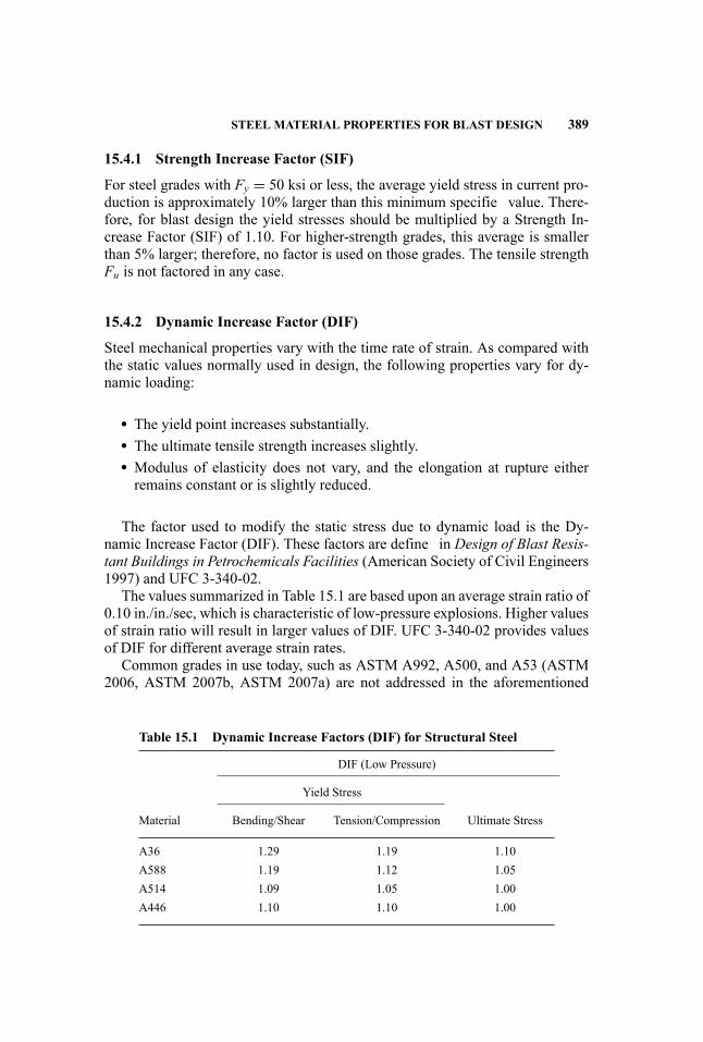
STEEL MATERIAL PROPERTIES FOR BLAST DESIGN 389
15.4.1 Strength Increase Factor (SIF)
For steel grades with Fy = 50 ksi or less, the average yield stress in current pro-duction is approximately 10% larger than this minimum specifie value. There-fore, for blast design the yield stresses should be multiplied by a Strength In-crease Factor (SIF) of 1.10. For higher-strength grades, this average is smallerthan 5% larger; therefore, no factor is used on those grades. The tensile strengthFu is not factored in any case.
15.4.2 Dynamic Increase Factor (DIF)
Steel mechanical properties vary with the time rate of strain. As compared withthe static values normally used in design, the following properties vary for dy-namic loading:
� The yield point increases substantially.� The ultimate tensile strength increases slightly.� Modulus of elasticity does not vary, and the elongation at rupture eitherremains constant or is slightly reduced.
The factor used to modify the static stress due to dynamic load is the Dy-namic Increase Factor (DIF). These factors are define in Design of Blast Resis-tant Buildings in Petrochemicals Facilities (American Society of Civil Engineers1997) and UFC 3-340-02.
The values summarized in Table 15.1 are based upon an average strain ratio of0.10 in./in./sec, which is characteristic of low-pressure explosions. Higher valuesof strain ratio will result in larger values of DIF. UFC 3-340-02 provides valuesof DIF for different average strain rates.
Common grades in use today, such as ASTM A992, A500, and A53 (ASTM2006, ASTM 2007b, ASTM 2007a) are not addressed in the aforementioned
Table 15.1 Dynamic Increase Factors (DIF) for Structural Steel
DIF (Low Pressure)
Yield Stress
Material Bending/Shear Tension/Compression Ultimate Stress
A36 1.29 1.19 1.10A588 1.19 1.12 1.05A514 1.09 1.05 1.00A446 1.10 1.10 1.00
390 DESIGN CONCEPTS AND MEMBER DETAILING: STEEL
references. All are normal construction grades, similar to ASTM A36 (ASTM2008), and suitable for use with the same DIF values.
15.4.3 Dynamic Design Stress
Based on the expected ductility ratio and/or the damage allowed in the structuralelement, different dynamic yield points are define by UFC 3-340-02. If theductility ratio is smaller than or equal to 10, the dynamic design stress is:
fds = fdy = SIF · DIF · fy (15.1)
If the ductility ratio is greater than 10, the dynamic design stress is:
fds = fdy + fdu − fdy4
(15.2)
where
fdu = DIF · fu (15.3)
The dynamic design stress for shear is
fdv = 0.55 fds (15.4)
For typical design, unless governed by more detailed requirements such asDesign of Blast Resistant Buildings in Petrochemical Facilities (ASCE 1997),UFC 3-340-02, or other established criteria, a simplifie value may be used asfollows:
fds = 1.3 fy (15.5)
fdu = 1.05 fu (15.6)
15.5 DESIGN CRITERIA FOR BLAST DESIGN
15.5.1 General
Due to the nature of blast loading, plastic design is required, and is measured bysupport rotations and ductility. Different codes can be used to defin the strengthof the elements, but no safety factor should be used in those calculations. Localand global stability should be addressed in those elements where plasticity mustbe achieved and ductility criteria must be used.
Design and failure criteria are based on the results of explosive tests conductedby the U.S. government and reported in publications such as the Tri-Service

DESIGN CRITERIA FOR BLAST DESIGN 391
Manual by the Department of Defense, and the Protective Design Manual bythe U.S. Air Force.
The designer should determine, at the beginning of the project, the acceptancecriteria to be used based on the level of protection desired for the building. Mostprojects have predefine criteria that must be used.
15.5.2 Load Combinations
In the absence of other governing criteria, the following load combination shouldbe used:
1.0D + 0.25L + 1.0B (15.7)
where D is the dead loadL is the live loadB is the blast load
15.5.3 Resistance Factor and Factor of Safety
For Load and Resistance Factor Design (LRFD), the resistance factor φ is notused in blast design. For Allowable Stress Design (ASD), the safety factor �
is not used in blast design. Thus, the strength is simply taken as the nominalstrength, without reduction.
15.5.4 Local Buckling
Blast design is based on the ultimate strength of the elements and ductility of thesystem. Structural members subject to blast loads should be capable of undergo-ing plastic deformation. To allow hinges to form in the elements, sections mustbe fl xurally compact in accordance with criteria in Chapter B of the AISC Spec-ificatio for Structural Steel Buildings (American Institute of Steel Construction2005b), unless the effects of local buckling can be tolerated in the response. Thedynamic design stress should be used in the calculation of the limiting slender-ness to establish the local buckling criteria.
15.5.5 Lateral-Torsional Buckling
Flexural members should be braced at an interval that is small enough to permitplastic hinge formation. Essentially, this removes lateral-torsional buckling asthe controlling limit state in beams.
15.5.6 Deformation Criteria
Support rotation is define as the tangent angle at the support formed by themaximum beam deflection In the plastic range, this value, neglecting the elasticdeformation, can be related to the plastic hinge rotation. Note that if the hinge is
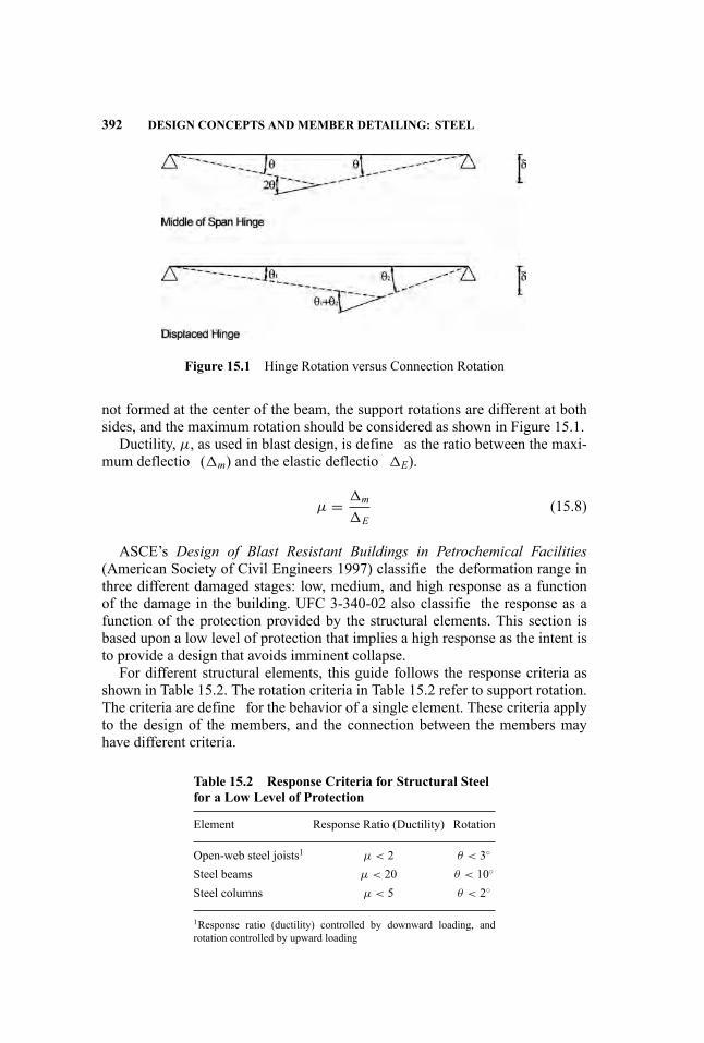
392 DESIGN CONCEPTS AND MEMBER DETAILING: STEEL
Figure 15.1 Hinge Rotation versus Connection Rotation
not formed at the center of the beam, the support rotations are different at bothsides, and the maximum rotation should be considered as shown in Figure 15.1.
Ductility, µ, as used in blast design, is define as the ratio between the maxi-mum deflectio (�m) and the elastic deflectio �E).
µ = �m
�E(15.8)
ASCE’s Design of Blast Resistant Buildings in Petrochemical Facilities(American Society of Civil Engineers 1997) classifie the deformation range inthree different damaged stages: low, medium, and high response as a functionof the damage in the building. UFC 3-340-02 also classifie the response as afunction of the protection provided by the structural elements. This section isbased upon a low level of protection that implies a high response as the intent isto provide a design that avoids imminent collapse.
For different structural elements, this guide follows the response criteria asshown in Table 15.2. The rotation criteria in Table 15.2 refer to support rotation.The criteria are define for the behavior of a single element. These criteria applyto the design of the members, and the connection between the members mayhave different criteria.
Table 15.2 Response Criteria for Structural Steelfor a Low Level of Protection
Element Response Ratio (Ductility) Rotation
Open-web steel joists1 µ < 2 θ < 3◦
Steel beams µ < 20 θ < 10◦
Steel columns µ < 5 θ < 2◦
1Response ratio (ductility) controlled by downward loading, androtation controlled by upward loading
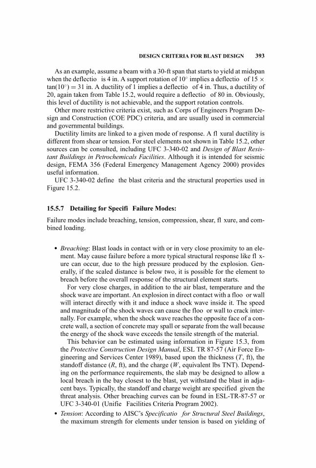
DESIGN CRITERIA FOR BLAST DESIGN 393
As an example, assume a beam with a 30-ft span that starts to yield at midspanwhen the deflectio is 4 in. A support rotation of 10◦ implies a deflectio of 15×tan(10◦) = 31 in. A ductility of 1 implies a deflectio of 4 in. Thus, a ductility of20, again taken from Table 15.2, would require a deflectio of 80 in. Obviously,this level of ductility is not achievable, and the support rotation controls.
Other more restrictive criteria exist, such as Corps of Engineers Program De-sign and Construction (COE PDC) criteria, and are usually used in commercialand governmental buildings.
Ductility limits are linked to a given mode of response. A fl xural ductility isdifferent from shear or tension. For steel elements not shown in Table 15.2, othersources can be consulted, including UFC 3-340-02 and Design of Blast Resis-tant Buildings in Petrochemicals Facilities. Although it is intended for seismicdesign, FEMA 356 (Federal Emergency Management Agency 2000) providesuseful information.
UFC 3-340-02 define the blast criteria and the structural properties used inFigure 15.2.
15.5.7 Detailing for Specifi Failure Modes:
Failure modes include breaching, tension, compression, shear, fl xure, and com-bined loading.
� Breaching: Blast loads in contact with or in very close proximity to an ele-ment. May cause failure before a more typical structural response like fl x-ure can occur, due to the high pressure produced by the explosion. Gen-erally, if the scaled distance is below two, it is possible for the element tobreach before the overall response of the structural element starts.For very close charges, in addition to the air blast, temperature and the
shock wave are important. An explosion in direct contact with a floo or wallwill interact directly with it and induce a shock wave inside it. The speedand magnitude of the shock waves can cause the floo or wall to crack inter-nally. For example, when the shock wave reaches the opposite face of a con-crete wall, a section of concrete may spall or separate from the wall becausethe energy of the shock wave exceeds the tensile strength of the material.This behavior can be estimated using information in Figure 15.3, from
the Protective Construction Design Manual, ESL TR 87-57 (Air Force En-gineering and Services Center 1989), based upon the thickness (T , ft), thestandoff distance (R, ft), and the charge (W, equivalent lbs TNT). Depend-ing on the performance requirements, the slab may be designed to allow alocal breach in the bay closest to the blast, yet withstand the blast in adja-cent bays. Typically, the standoff and charge weight are specified given thethreat analysis. Other breaching curves can be found in ESL-TR-87-57 orUFC 3-340-01 (Unifie Facilities Criteria Program 2002).
� Tension: According to AISC’s Specificatio for Structural Steel Buildings,the maximum strength for elements under tension is based on yielding of
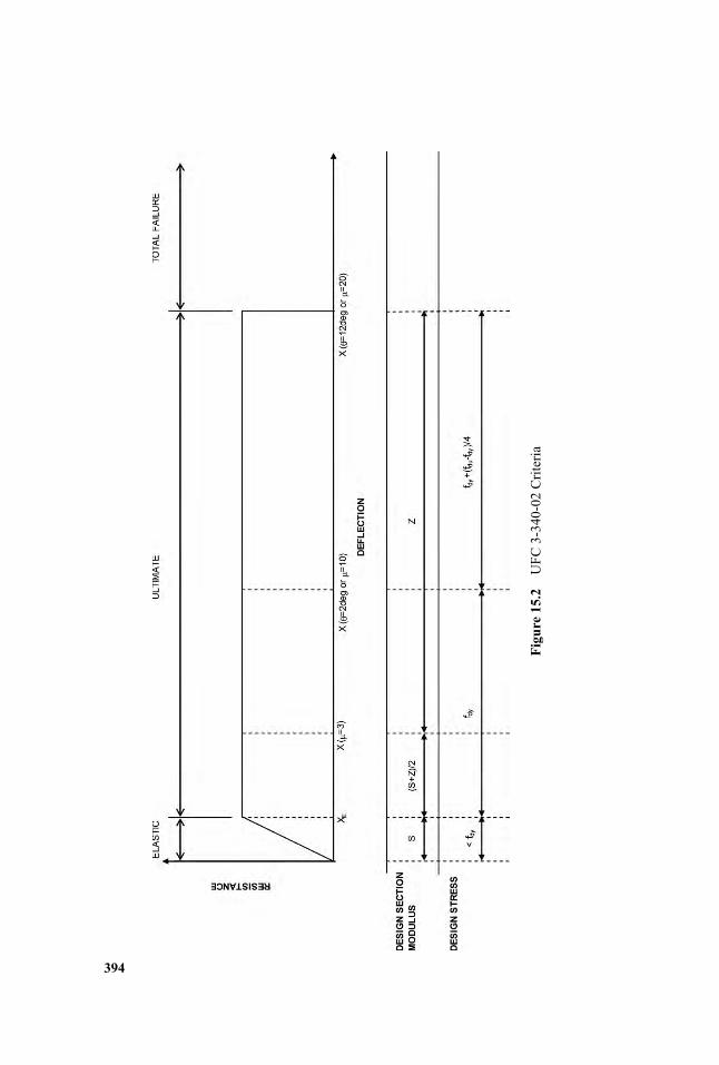
Figure15.2
UFC
3-340-02
Criteria
394
DESIGN CRITERIA FOR BLAST DESIGN 395
Figure 15.3 Protective Construction Manual Breach Chart
the member and is define by
Pu = φ fy Ag (15.9)
where Ag = the gross area of the elementfy = the material yield stressφ = the resistance factor, 0.90
For blast loading, φ is not used, and fy = fds is the dynamic design stressdefine in Equations 15.1 and 15.2.Axial hinge properties for these kinds of elements are elastic-plastic,
based on the ultimate load define above. If necessary, for computationalstability, a small strain hardening slope, such as 0.1%, can be used in theplastic area.
� Compression: The strength of compression elements, based on the AISCSpecificatio for Structural Steel Buildings, is governed by the followingequation:
Pu = φ fcr Ag (15.10)
where Ag = the gross area of the elementfcr = the critical stressφ = 0.90
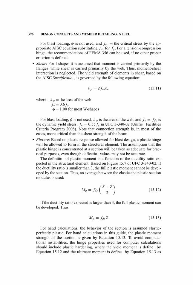
396 DESIGN CONCEPTS AND MEMBER DETAILING: STEEL
For blast loading, φ is not used, and fcr = the critical stress by the ap-propriate AISC equation substituting fds for fy . For a tension-compressionhinge, the recommendations of FEMA 356 can be used, if no other propercriterion is defined
� Shear: For I-shapes it is assumed that moment is carried primarily by theflanges while shear is carried primarily by the web. Thus, moment-shearinteraction is neglected. The yield strength of elements in shear, based onthe AISC Specificatio , is governed by the following equation:
Vp = φ fvAw (15.11)
where Aw = the area of the webfv = 0.6 fyφ = 1.00 for most W-shapes
For blast loading, φ is not used, Aw is the area of the web, and fv = fdv isthe dynamic yield stress; fv = 0.55 fy in UFC 3-340-02 (Unifie FacilitiesCriteria Program 2008). Note that connection strength is, in most of thecases, more critical than the shear strength of the beam.
� Flexure: Based on plastic response allowed for blast design, a plastic hingewill be allowed to form in the structural element. The assumption that theplastic hinge is concentrated at a section will be taken as adequate for prac-tical purposes, even though deflectio values may not be accurate.The definitio of plastic moment is a function of the ductility ratio ex-
pected in the structural element. Based on Figure 15.7 of UFC 3-340-02, ifthe ductility ratio is smaller than 3, the full plastic moment cannot be devel-oped by the section. Thus, an average between the elastic and plastic sectionmodulus is used:
Mp = fds(S + Z2
)(15.12)
If the ductility ratio expected is larger than 3, the full plastic moment canbe developed. Thus,
Mp = fds Z (15.13)
For hand calculations, the behavior of the section is assumed elastic-perfectly plastic. For hand calculations in this guide, the plastic momentstrength of the section is given by Equation 15.13. To avoid computa-tional instabilities, the hinge properties used for computer calculationsshould include plastic hardening, where the yield moment is define byEquation 15.12 and the ultimate moment is define by Equation 15.13 as

EXAMPLES 397
recommended in UFC 3-340-02. A criterion for lateral bracing is also givenin UFC 3-340-02 although not discussed here.
� Combined Forces: Provisions for combined axial and bending effects arepresented in the AISC Specificatio . The strengths and resistance factorsdefine above are used in the appropriate interaction equations.
15.6 EXAMPLES
15.6.1 Example 1—Determining Capacities
The strength of the elements determined in these examples is based on UFC3-340-02. For element design, it is assumed that there is no energy dissipationalong the load path. A more accurate and less conservative procedure is to usethe dynamic reactions of one member on another along the load path.
When using member reactions to load following members, natural frequenciesshould be compared. If the natural frequencies are close, a simultaneous solutionis required to account for the interaction between the two members. If the periodof the primary element (i.e., beam) is at least twice the period of the secondaryelement (i.e., girder), they can be treated as individual SDOF structures on un-yielding supports. If not, an MDOF solution of the same system should be used.
Material Properties All calculations for this example are done for steel withthe following properties:
� Fy = 50 ksi� Fu = 70 ksi
For a ductility ratio µ ≤ 10, the dynamic design stress, define in Equation15.5, is:
fds = fdy = 1.3Fy = 1.3× 50 = 65 ksi
For a ductility ratio µ > 10, the dynamic design stress, define in Equation15.2, is:
fds = fdy +(fdu − fdy
4
)= 65+
(1.05× 70− 65
4
)= 67 ksi
where: fdu = 1.05fu from Equation 15.6.
The dynamic design shear stress, define in Equation 15.4, for a ductility ratioµ ≤ 10 is:
fdv = 0.55× fds = 0.55× 65 = 36 ksi

398 DESIGN CONCEPTS AND MEMBER DETAILING: STEEL
Figure 15.4 Tension Hinge Property
Tension-Only Rod Brace A tension rod with 3/4-in. diameter is used. Becausethe rod has upset ends, we can use the full cross section area. The tension strengthis obtained as:
Tmax = A fds = π ×(3/42
)2
× 65 = 28.7 kips
The hinge property for this rod follows the elastic-plastic curve shown inFigure 15.4. A slight slope is included in the plastic region for computationalconvergence purposes.
Given a maximum horizontal displacement of 4.2 in., the maximum rotationat the base of the column for this displacement is:
α = atan(
�
H
)= atan
(4.2
15× 12
)= 1.34 deg < 2 deg
For a small-displacement formulation, the elongation in the rod can be deter-mined. First, the angle of the diagonal is determined:
θ = atan(HL
)= atan
(1535
)= 23.2 deg
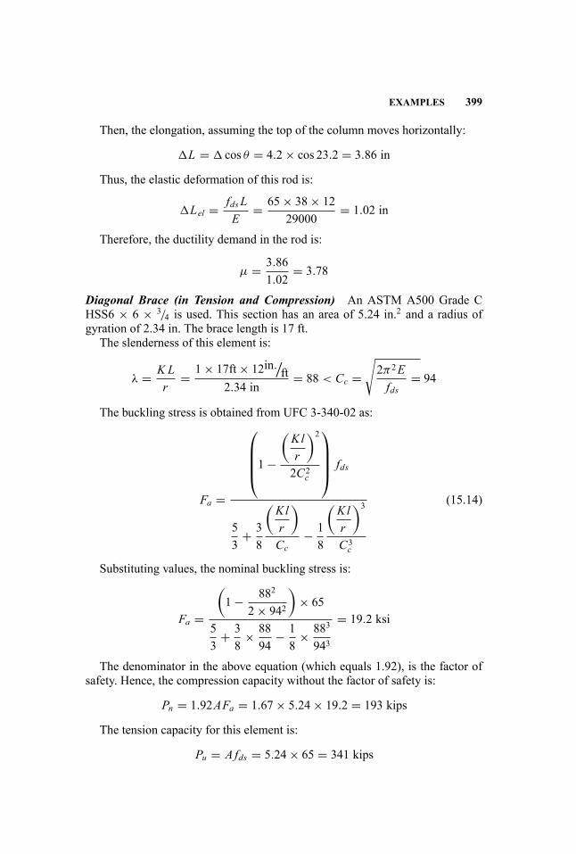
EXAMPLES 399
Then, the elongation, assuming the top of the column moves horizontally:
�L = � cos θ = 4.2× cos 23.2 = 3.86 in
Thus, the elastic deformation of this rod is:
�Lel = fds LE
= 65× 38× 1229000
= 1.02 in
Therefore, the ductility demand in the rod is:
µ = 3.861.02
= 3.78
Diagonal Brace (in Tension and Compression) An ASTM A500 Grade CHSS6 × 6 × 3/4 is used. This section has an area of 5.24 in.2 and a radius ofgyration of 2.34 in. The brace length is 17 ft.
The slenderness of this element is:
λ = K Lr
= 1× 17ft× 12in./ft
2.34 in= 88 < Cc =
√2π2Efds
= 94
The buckling stress is obtained from UFC 3-340-02 as:
Fa =
⎛⎜⎜⎜⎝1−
(Klr
)2
2C2c
⎞⎟⎟⎟⎠ fds
53
+ 38
(Klr
)
Cc− 18
(Klr
)3
C3c
(15.14)
Substituting values, the nominal buckling stress is:
Fa =
(1− 882
2× 942
)× 65
53
+ 38
× 8894
− 18
× 883
943
= 19.2 ksi
The denominator in the above equation (which equals 1.92), is the factor ofsafety. Hence, the compression capacity without the factor of safety is:
Pn = 1.92AFa = 1.67× 5.24× 19.2 = 193 kips
The tension capacity for this element is:
Pu = A fds = 5.24× 65 = 341 kips
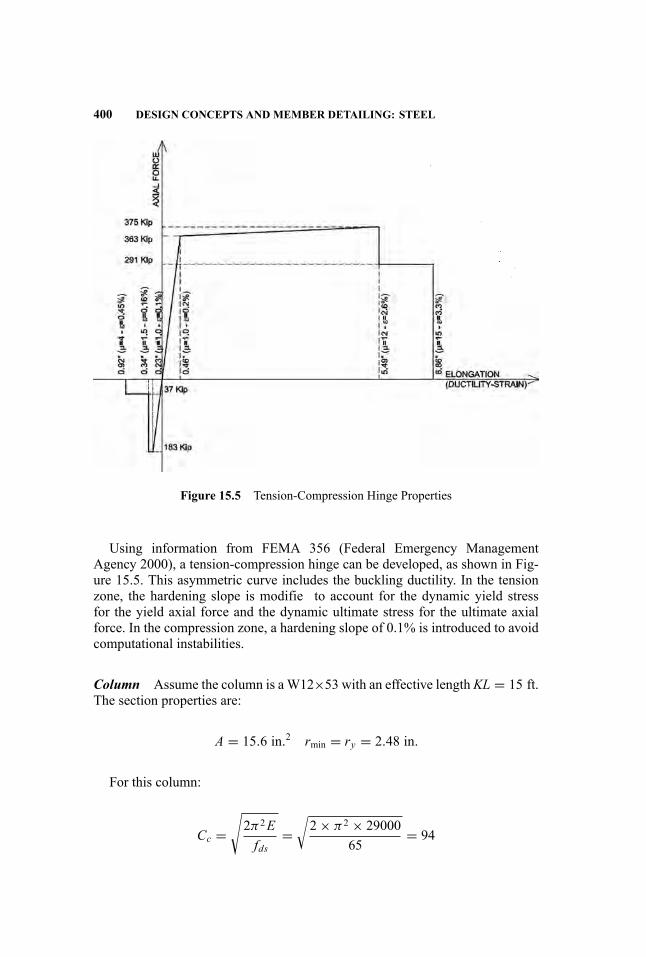
400 DESIGN CONCEPTS AND MEMBER DETAILING: STEEL
Figure 15.5 Tension-Compression Hinge Properties
Using information from FEMA 356 (Federal Emergency ManagementAgency 2000), a tension-compression hinge can be developed, as shown in Fig-ure 15.5. This asymmetric curve includes the buckling ductility. In the tensionzone, the hardening slope is modifie to account for the dynamic yield stressfor the yield axial force and the dynamic ultimate stress for the ultimate axialforce. In the compression zone, a hardening slope of 0.1% is introduced to avoidcomputational instabilities.
Column Assume the column is aW12×53 with an effective length KL = 15 ft.The section properties are:
A = 15.6 in.2 rmin = ry = 2.48 in.
For this column:
Cc =√2π2Efds
=√2× π2 × 29000
65= 94
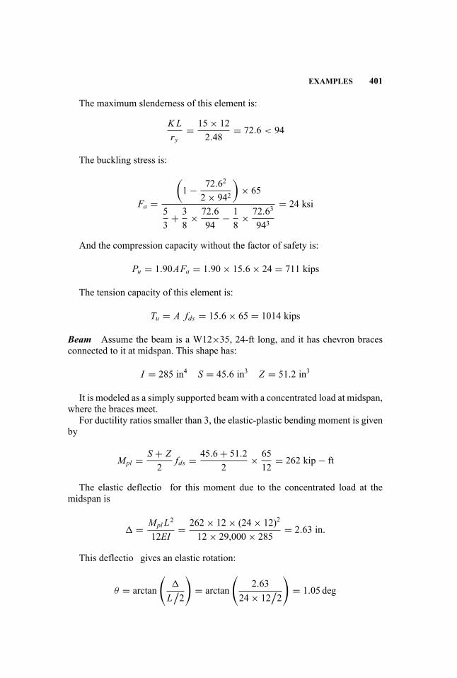
EXAMPLES 401
The maximum slenderness of this element is:
K Lry
= 15× 122.48
= 72.6 < 94
The buckling stress is:
Fa =
(1− 72.62
2× 942
)× 65
53
+ 38
× 72.694
− 18
× 72.63
943
= 24 ksi
And the compression capacity without the factor of safety is:
Pu = 1.90AFa = 1.90× 15.6× 24 = 711 kips
The tension capacity of this element is:
Tu = A fds = 15.6× 65 = 1014 kips
Beam Assume the beam is a W12×35, 24-ft long, and it has chevron bracesconnected to it at midspan. This shape has:
I = 285 in4 S = 45.6 in3 Z = 51.2 in3
It is modeled as a simply supported beam with a concentrated load at midspan,where the braces meet.
For ductility ratios smaller than 3, the elastic-plastic bending moment is givenby
Mpl = S + Z2
fds = 45.6+ 51.22
× 6512
= 262 kip− ft
The elastic deflectio for this moment due to the concentrated load at themidspan is
� = Mpl L2
12EI= 262× 12× (24× 12)2
12× 29,000× 285= 2.63 in.
This deflectio gives an elastic rotation:
θ = arctan
(�
L/2
)= arctan
(2.63
24× 12/2
)= 1.05 deg

402 DESIGN CONCEPTS AND MEMBER DETAILING: STEEL
Mult = Z × fds (µ > 10)
2θult2θ
Mpl = fdsS + Z
2M
omen
t
Rotation
Figure 15.6 Beam Hinge Moment-Rotation
Note that the hinge rotation is twice this support rotation. These parametersdefin an elastic-perfectly plastic moment-rotation curve. Since many programshave convergence problems with a perfectly plastic zone, a sloped line should beintroduced in this plastic region. This slope is obtained from Figure 15.6 for duc-tility greater than 10. Therefore, the ultimate bending moment is computed as:
Mult = Z × fds (µ > 10) = 51.2× 6712
= 286 kips− ft
The maximum rotation from UFC 3-340-02 is:
θult = min (10 deg, 20× θ) = min (10 deg, 26 deg) = 10 deg
Again, note that hinge rotation is twice this support rotation.
15.6.2 Example 2—Design and Analysis for Blast Loads on Members
Figures 15.7 and 15.8 illustrate the method used in this example for a simplysupported beam with load and mass uniformly distributed.
The same transformation as shown in Figure 15.7 can be done by multiplyingonly the mass by the load-mass factor.
MSDOF = MKLM = MKM
KL
The KLM approach is simpler because it only uses one transformation factor.This example uses the load factor KL and the mass factor KM because they havea more physical interpretation.
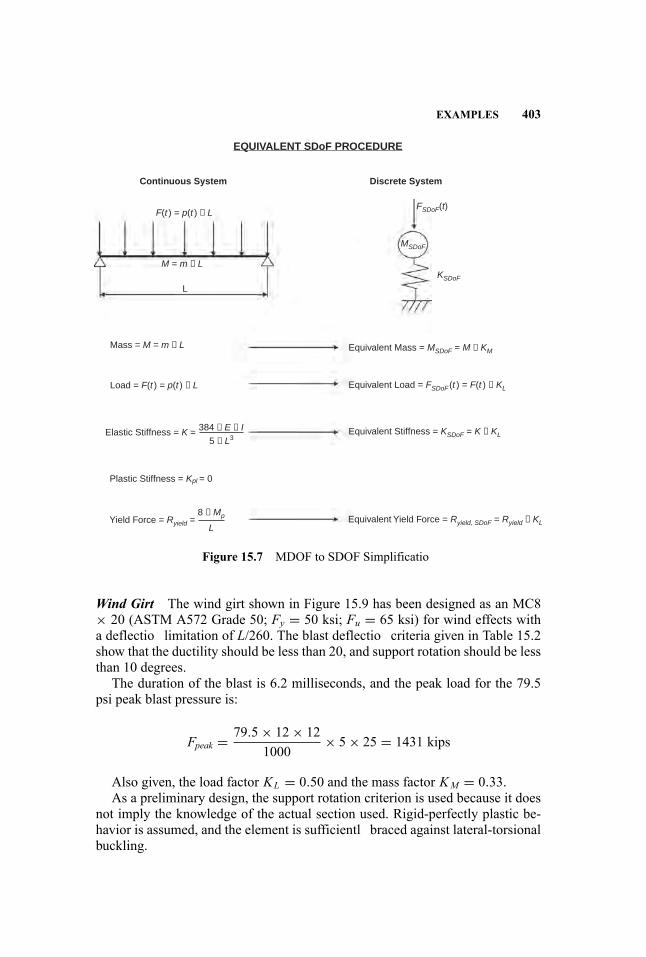
EXAMPLES 403
EQUIVALENT SDoF PROCEDURE
Continuous System
F(t ) = p(t ) × L
M = m × L
Mass = M = m × L
Load = F(t ) = p(t ) × L
384 × E × I
5 × L3
8 × Mp
Elastic Stiffness = K =
Plastic Stiffness = Kpl = 0
Equivalent Mass = MSDoF = M × KM
Equivalent Load = FSDoF (t ) = F(t ) × KL
Equivalent Stiffness = KSDoF = K × KL
Equivalent Yield Force = Ryield, SDoF = Ryield × KLYield Force = Ryield =
Discrete System
L
FSDoF(t)
MSDoF
KSDoF
L
Figure 15.7 MDOF to SDOF Simplificatio
Wind Girt The wind girt shown in Figure 15.9 has been designed as an MC8× 20 (ASTM A572 Grade 50; Fy = 50 ksi; Fu = 65 ksi) for wind effects witha deflectio limitation of L/260. The blast deflectio criteria given in Table 15.2show that the ductility should be less than 20, and support rotation should be lessthan 10 degrees.
The duration of the blast is 6.2 milliseconds, and the peak load for the 79.5psi peak blast pressure is:
Fpeak = 79.5× 12× 121000
× 5× 25 = 1431 kips
Also given, the load factor KL = 0.50 and the mass factor KM = 0.33.As a preliminary design, the support rotation criterion is used because it does
not imply the knowledge of the actual section used. Rigid-perfectly plastic be-havior is assumed, and the element is sufficientl braced against lateral-torsionalbuckling.
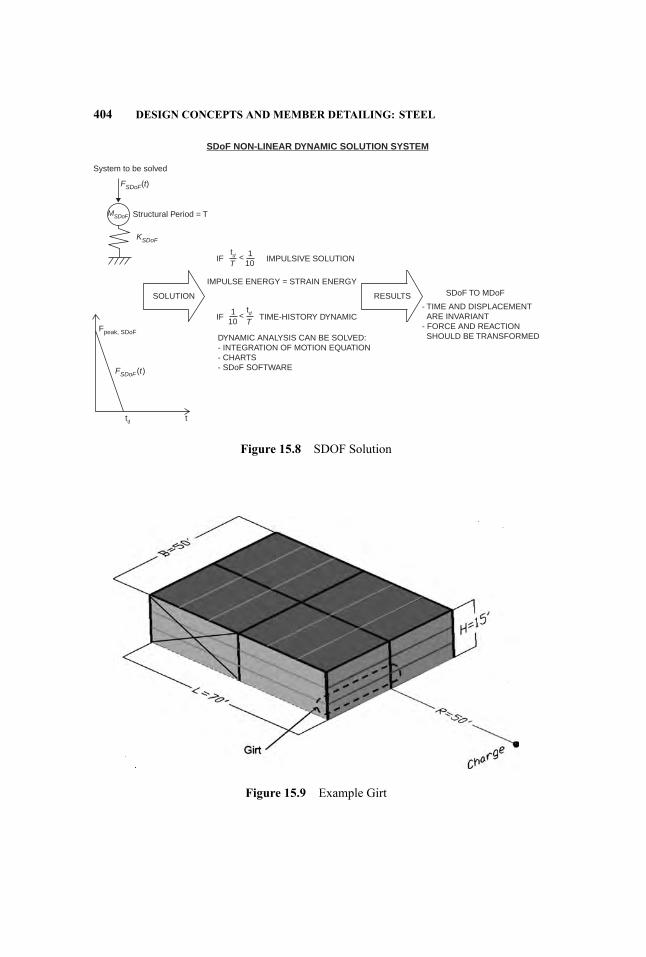
404 DESIGN CONCEPTS AND MEMBER DETAILING: STEEL
Structural Period = T
IF1
10<
td
td t
T
IMPULSE ENERGY = STRAIN ENERGY
IMPULSIVE SOLUTION
SOLUTION
Fpeak, SDoF
RESULTS SDoF TO MDoF
- TIME AND DISPLACEMENT ARE INVARIANT- FORCE AND REACTION SHOULD BE TRANSFORMED
SDoF NON-LINEAR DYNAMIC SOLUTION SYSTEM
System to be solved
FSDoF(t)
FSDoF (t)
MSDoF
KSDoF
IF1
10<
tdT
TIME-HISTORY DYNAMIC
DYNAMIC ANALYSIS CAN BE SOLVED:- INTEGRATION OF MOTION EQUATION- CHARTS- SDoF SOFTWARE
Figure 15.8 SDOF Solution
Figure 15.9 Example Girt

EXAMPLES 405
For this rotation criterion, the maximum displacement allowed is:
�max = 25× 122
× sin (10 deg) = 26 in.
The self weight of the facade is 40 psf. The total weight of the system is:
w = 40× 25× 51000
= 5 kips
Based on the single-degree-of-freedom simplificatio used for mass and loadsuniformly distributed in the plastic range, the load and stiffness are multipliedby the load factor KL = 0.50, and the mass is multiplied by the mass factorKM = 0.33. Therefore, the parameters used in the discrete system are:
Fpeak,SDOF = FpeakKL = 1431× 0.5 = 715 kips wSDOF
= wKM = 5× 0.33 = 1.65 kips
The equivalent impulse in this single-degree-of-freedom system is:
ISDOF = Fpeak,SDOF tblast2
= 715× 6.2× 10−3
2= 2.2 kips− sec
The total energy produced by the blast load in the single-degree-of-freedomis:
WImpulse,SDOF = I 2SDOF2mSDOF
= 2.22
2× 1.65386
= 566 kips− in
To limit the maximum displacement to comply with the support rotation cri-teria, the single-degree-of-freedom yield force should be:
Ryield,SDOF = WImpulse,SDOF
�max= 566
26= 21.8 kips
The yield force for the continuous system is:
Ryield = 21.80.5
= 43.6 kips
For this yield force, the maximum moment is:
Mpl = Ryield L8
= 43.6× 258
= 136 kips− ft

406 DESIGN CONCEPTS AND MEMBER DETAILING: STEEL
For a maximum tensile strength of 65 ksi, the plastic modulus should begreater than:
Zmin = 136× 1265
= 25 in3
Based on this preliminary design, there is no MC8 strong enough to supportthe blast. There are several possible modification to improve the behavior of thesystem: Increase the excited mass, increase the strength-stiffness of the system,or decrease the blast load by integrating a variable blast pressure that is a functionof the distance to the charge along the girt.
In this example we will increase the steel section to a W8× 28 (ASTMA992;Fy = 50 ksi; Fu = 65 ksi):
Zx = 27.2 in3 Mpl = Z fds = 27.2× 6512
= 147 kip− ft
Ix = 98 in4
�el = 548Mpl L2
E I= 5
48147× 12× (25× 12)2
29,000× 98= 5.82 in
The strength parameters to use in the dynamic calculation are:
Ryield = 8Mpl
L= 8× 147
25= 47.0 kips for the SDOF
Ryield,SDOF = Ryield KL = 47.0× 0.5 = 23.6 kips
K = Ryield�el
= 475.82
= 8.08 kips/in for the SDOF
KSDOF = KKL = 8.08× 0.5 = 4.04 kips/in
The mass and load do not change from the latest calculations.The period of the system is:
T = 2π√mSDOF
KSDOF= 2× π ×
√1.65
386× 4.04= 0.20 sec
The structural period (0.20 sec) is more than 10 times longer than the loadduration (0.0062 sec), hence the assumption of impulsive load is correct.
Figure 15.10 shows the displacement computed using SDOF software. Themaximum deflectio is 28.8 in. > 26.0 in.; hence, the rotation criterion is notmet by a slight margin.
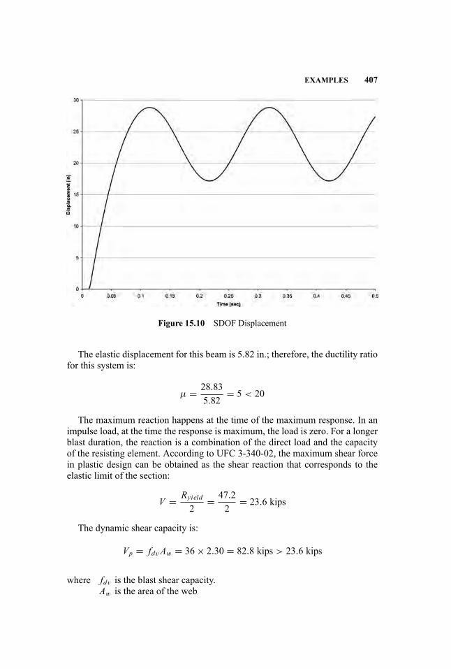
EXAMPLES 407
Figure 15.10 SDOF Displacement
The elastic displacement for this beam is 5.82 in.; therefore, the ductility ratiofor this system is:
µ = 28.835.82
= 5 < 20
The maximum reaction happens at the time of the maximum response. In animpulse load, at the time the response is maximum, the load is zero. For a longerblast duration, the reaction is a combination of the direct load and the capacityof the resisting element. According to UFC 3-340-02, the maximum shear forcein plastic design can be obtained as the shear reaction that corresponds to theelastic limit of the section:
V = Ryield2
= 47.22
= 23.6 kips
The dynamic shear capacity is:
Vp = fdvAw = 36× 2.30 = 82.8 kips > 23.6 kips
where fdv is the blast shear capacity.Aw is the area of the web

408 DESIGN CONCEPTS AND MEMBER DETAILING: STEEL
Hence, the section can support the shear. The connection should be designedfor this capacity.
Facade Column The column shown in Figure 15.11 has been designed as aW12 × 53 (ASTM A992; Fy = 50 ksi; Fu = 65 ksi) for wind effects with adeflectio limitation of L/260. The properties of this section are:
A = 15.6 in.Ix = 425 in .4 Zx = 77.9 in.3ry = 2.48 in. rx = 5.23 in.
As for the wind girt, the duration of the blast is 6.2 milliseconds, and the peakload for the 79.5 psi peak blast pressure is:
Fpeak = 79.5× 12× 121000
× 5× 25 = 1431 kips
Also given, the load factor KL = 0.50 and the mass factor KM = 0.33.Columns are designed to remain elastic; therefore, the maximum bending ca-
pacity should not be reached. As a preliminary design, the column will be de-signed without axial compression. Combined bending compression formulationwill be used to check the adequacy of this element.
Figure 15.11 Example Column

EXAMPLES 409
As a preliminary and conservative assumption, the girt is assumed infinitelrigid, and all the blast pressure is absorbed by the column.
The self weight of the facade is 40 psf. The total weight of the system is:
w = 40× 25× 151000
= 15 kips
The peak load for the 79.5 psi peak blast pressure is:
Fpeak = 79.5× 12× 121000
× 15× 25 = 4293 kips
Based on the single-degree-of-freedom simplificatio used for mass and loadsuniformly distributed in the plastic range, the load and the stiffness are multipliedby the load factor KL = 0.50, and the mass is multiplied by the mass factorKM = 0.33.Therefore, the parameters used in the discrete system are:
Fpeak,SDOF = 0.5× 4293 = 2146 kipswSDOF = 0.33× 15 = 4.95 kips
The equivalent impulse in this single-degree-of-freedom system is:
ISDOF = Fpeak,SDOF tblast2
= 2146× 6.2× 10−3
2= 6.65 kips− sec
The total energy produced by the blast load in the single-degree-of-freedom is:
WImpulse,SDOF = I 2SDOF2mSDOF
= 6.652
2× 4.95386
= 1724 kip− in.
For thisW12× 53, assuming a uniformly distributed load, the following prop-erties defin the structural behavior:
Mpl = Zfds = 77.9× 6512
= 422 kip− ft
�el = 548Mpl L2
E I= 5
48422× 12× (15× 12)2
29,000× 425= 1.38 in.

410 DESIGN CONCEPTS AND MEMBER DETAILING: STEEL
The parameters to use in the dynamic calculation are:
Ryield = 8Mpl
L= 8× 422
15= 225 kips, for the SDOF
Ryield,SDOF = Ryield KL = 225× 0.5 = 112.5 kips
K = Ryield�el
= 2251.38
= 163 kips/in., for the SDOF
KSDOF = 163× 0.5 = 81.5 kips/in.
The period of the system is:
T = 2π√mSDOF
KSDOF= 2× π ×
√4.95
386× 81.5= 0.08 sec
The column period (0.08 sec) is more than 10 times the load duration (0.0062sec); hence, the assumption of impulsive load can be assumed. The period ofthe column is smaller than half of the beam period (0.08 sec < 0.20
2 = 0.1 sec);hence, the system is uncoupled and can be modeled separately.
Assuming elastic behavior, the maximum elastic energy that can be adsorbedby the SDOF system is given by the equation:
WS,el,max = R2yield,SDOF2KSDOF
= 112.52
2× 81.5= 77.6 kips− in. � 1724 kips− in.
This energy is smaller than the energy induced by the impulse; hence, this el-ement will achieve plastic behavior. There is not an economical solution to solvethis problem because of the element’s inability to remain elastic for a directlyapplied tributary blast load. But the preliminary assumption that based this de-sign in the rigid behavior of the girt is highly conservative; the maximum loadthat this element is carrying comes from the reaction in the girt.
Assuming this reaction is static, the system to solve is define in Figure 15.12.The maximum bending moment for this configuratio is:
Mx = 2× 23.6× 153
= 236 kips− ft
The axial load at the column, based on 30 psf roof dead load, is:
P = 30× 502
× 704
= 13.1 kips
In the following, the capacity properties of this element are calculated to beused in the interaction axial-bending curves.
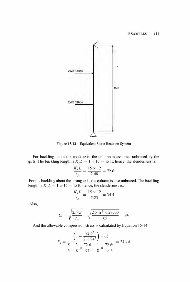
EXAMPLES 411
Figure 15.12 Equivalent Static Reaction System
For buckling about the weak axis, the column is assumed unbraced by thegirts. The buckling length is KyL = 1× 15 = 15 ft; hence, the slenderness is:
KyLry
= 15× 122.48
= 72.6
For the buckling about the strong axis, the column is also unbraced. The bucklinglength is Kx L = 1× 15 = 15 ft; hence, the slenderness is:
Kx Lrx
= 15× 125.23
= 34.4
Also,
Cc =√2π2Efds
=√2× π2 × 29000
65= 94
And the allowable compression stress is calculated by Equation 15-14:
Fa =
(1− 72.62
2× 942
)× 65
53
+ 38
× 72.694
− 18
× 72.63
943
= 24 ksi

412 DESIGN CONCEPTS AND MEMBER DETAILING: STEEL
The nominal compression capacity results:
Pu = 1.90AFa = 1.90× 15.6× 24 = 711 kips
The Euler stress in the x-axis is:
Fex = 12π2E23λ2x
= 12× π2 × 2900023× 342
= 129 ksi
In this equation, 12/23 is the factor of safety for buckling. And the unfactoredEuler load in the x-axis results:
Pex = 2312AFex = 23
12× 15.6× 129 = 3857 kips
The tension capacity is:
Pp = A fds = 15.6× 65 = 1014 kips
The plastic moment was calculated before as:
Mpl,x = Zx fds = 77.9× 6512
= 422 kip− ft
This value was calculated assuming the member was completely braced, butthis beam is laterally unsupported because the girts cannot carry any axial loadafter the blast. Hence, the unbraced fl xural strength is:
Mm,x =(1.07− L/ry
√fds
3160
)Mpl,x =
(1.07− 15× 12/2.48× √
653160
)
×422 = 0.88× 422 = 371 kip− ft
The firs interaction curve that the system should satisfy is:
PPu
+ CmxMx(1− P
Pex
)Mmx
= 13.1636
+ 1× 236(1− 13.1
3857
)× 371
= 0.015+ 0.64 = 0.65 ≤ 1
where
Cmx = 1
All the other parameters were define previously.The second interaction curve to accomplish is:
Mx
Mpl,x= 236
422= 0.56 ≤ 1 for
PPp
= 13.11014
= 0.013 < 0.15

EXAMPLES 413
Figure 15.13 Composite Beam Section
This calculation does not consider the reduced stiffness due to the interactionof bending and compression. For higher compression loads and if the momentmagnifie is bigger than 10 percent, the analysis should consider second-ordereffects.
Composite Beam In this example, the composite beam shown in Figure 15.13will be designed for the roof blast load. The structure is a 25-ft span compositebeam, W14 × 22 with a 51/2 slab with a 3′′ metal deck. The concrete strengthis 3.0 ksi. For blast design, this strength is multiplied by 1.12. The steel used isGrade 50, as in the previous examples.
The section properties based on the blast strength for the concrete and thesteel are:
I = 830 in.4Mpl = 395 kip− ft
For rebound purposes, the moment capacity of the steel, based on Z =33.2 in3, is:
Mpl,steel = Z fdy = 33.2(65)12
= 180 kip− ft
The load to be used for this example is shown in Figure 15.14.Finally, assume that the existing dead load is 60 psf.The total weight for the beam is:
w = 60× 25× 61000
= 9 kips
The peak load for the 12.2 psi peak blast pressure is:
Fpeak = 12.2× 12× 121000
× 6× 25 = 263 kips
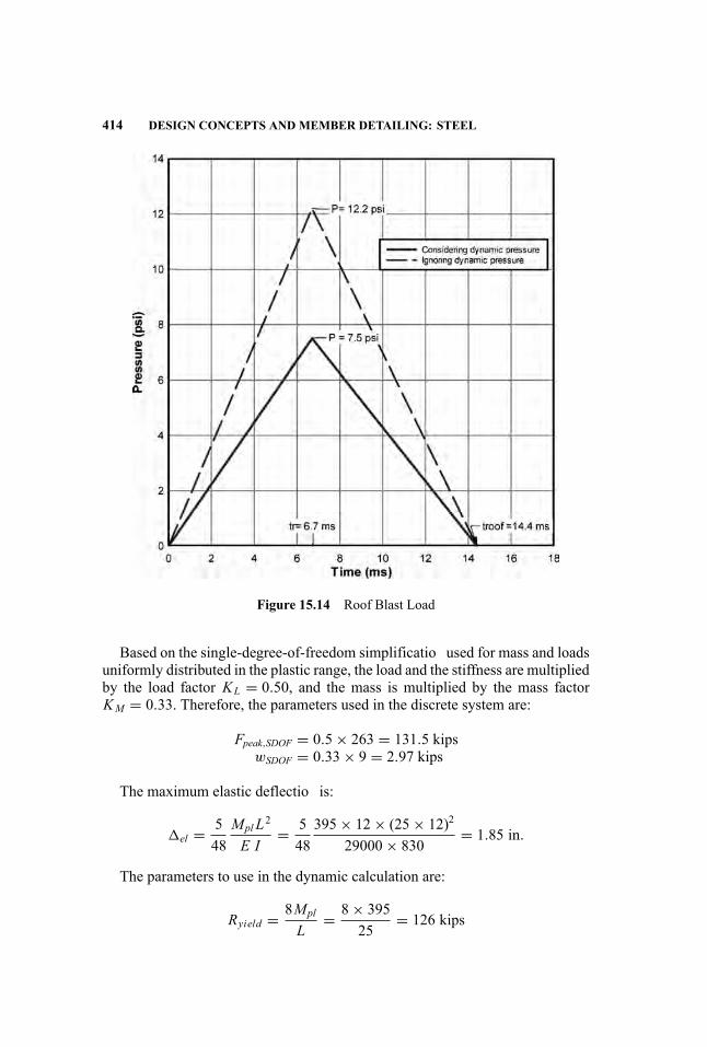
414 DESIGN CONCEPTS AND MEMBER DETAILING: STEEL
Figure 15.14 Roof Blast Load
Based on the single-degree-of-freedom simplificatio used for mass and loadsuniformly distributed in the plastic range, the load and the stiffness are multipliedby the load factor KL = 0.50, and the mass is multiplied by the mass factorKM = 0.33. Therefore, the parameters used in the discrete system are:
Fpeak,SDOF = 0.5× 263 = 131.5 kipswSDOF = 0.33× 9 = 2.97 kips
The maximum elastic deflectio is:
�el = 548Mpl L2
E I= 5
48395× 12× (25× 12)2
29000× 830= 1.85 in.
The parameters to use in the dynamic calculation are:
Ryield = 8Mpl
L= 8× 395
25= 126 kips

EXAMPLES 415
For the design of this beam, the existing dead load is applied simultaneouslywith the blast load and will reduce the beam capacity.
Ryield,reduced = 126− 9 = 117 kips. For the SDOF
Ryield,SDOF = 117× 0.5 = 58.5 kips
K = Ryield�el
= 1261.85
= 68 kips/in. For the SDOF
KSDOF = 68× 0.5 = 34 kips/in.
The period of the system is:
T = 2π√mSDOF
KSDOF= 2π
√wSDOF
gKSDOF= 2π
√2.97
386× 34= 0.09 sec
For this example, the beam period is less than 10 times the loadduration,0.09 sec < 10(0.0144) = 0.144 sec; hence, the impulse formulationcannot be used.
For the rebound
Ryield,steel = 8Mpl,steel
L= 8× 180
25= 57.6 kips
The elastic deflectio for the noncomposite steel beam is:
�el,steel = 40384
Mpl,steel L2
E Isteel= 40
384180× 12× (25× 12)2
29000× 199= 3.50 in.
The maximum negative force is:
RRebound,SDOF = 0.5× 57.6 kips = 28.8 kips
Therefore, the elastic stiffness at the rebound is:
KRebound,SDOF = RRebound,SDOF�el,steel
= 28.83.50
= 8.22 kips/in.
The period at the rebound is:
T = 2π√ mSDOF
KRebound,SDOF= 2× π ×
√2.97
386× 8.22= 0.19 sec

416 DESIGN CONCEPTS AND MEMBER DETAILING: STEEL
For the rebound, the beam period is greater than 10 times the loadduration,0.19 sec > 0.0144 sec; hence, the impulse formulation can be used forthe rebound response.
The parameters for the load used in the analysis were previously calculated:
wSDOF = 2.97 kips Fpeak,SDOF = 131.5 kips
The load is applied follow the timing shown in Figure 15.14.The yield and stiffness were obtained previously as:
Ryield,SDOF = 58.5 kips KSDOF = 34 kips/in.
And the rebound properties are:
RRebound,SDOF = 28.8 kips KRebound,SDOF = 8.22 kips/in
Using nonlinear SDOF software, the maximum displacement is (seeFigure 15.15):
�SDOF = 1.84 in. �SDOF,Rebound = 3.61 in.
Figure 15.15 SDOF Displacement

EXAMPLES 417
The dead load deflectio should be added to the solution obtained by SDOF.
�dead = 5384
WL3
E I= 5
3849× (25× 12)3
29000× 830= 0.13 in.
The maximum deflectio results:
�max = �SDOF + �dead = 1.84+ 0.13 = 1.97 in.
Hence, the ductility results:
µ = �max
�el= 1.97
1.85= 1.06
For the rebound, the ductility is:
µ = 3.613.50
= 1.03
For the SDOF solution the element behaves as a composite member andyields during the rebound. Figure 15.16 shows the force resultant from the SDOFsystem.
Figure 15.16 SDOF Force
418 DESIGN CONCEPTS AND MEMBER DETAILING: STEEL
The maximum shear force in plastic design can be obtained as the shear reac-tion that plastifie the section:
V = Ryield2
= 1262
= 63 kips
The dynamic shear capacity is:
Vp = fdvAw = 36× 2.76 = 99.4 kips > 63 kips
where fdv is the blast shear capacityAw is the area of the web
Hence, the section can support the shear. The connection should be designedfor this capacity
15.7 DESIGN OF CONNECTIONS
Connections require as much attention as members, especially in blast design.Failures of steel structures under overload can initiate at the connections of mem-bers, as opposed to the members themselves, for many reasons:
� The design of members is often controlled by considerations other thanstrength, including deflection vibration control, and architectural require-ments. Such members are often substantially stronger than required to re-sist the design forces. Connections, however, typically can be designedbased only on considerations of strength. When this is the case, there maybe less overstrength or reserve capacity to match the overstrength of themembers.
� Connections may be controlled by limit states with varying levels of duc-tility. When less ductile limit states, such as tension rupture or block shearrupture control, there is less capacity for redistribution of forces and themobilization of ductile behavior.
� Connections tend to be of limited size and, therefore, even when exhibitingductile behavior, they can only accommodate limited plastic deformationbefore reaching their ultimate capacities
It is important in the design of blast-resistant structures, particularly thoseexpected to be loaded into the inelastic range of behavior, that sudden failuremodes be avoided so that the plastic response of the structure can be mobilized.It is also important to remember that blast loading may result in load reversal,

REFERENCES 419
Table 15.3 Dynamic Increase Factors for Connection Design
Connection Material Action Yield Strength Ultimate Strength
Plate, A36, A572 Bending/shear 1.3 1.1Tension/compression/bearing 1.2 1.1
Plate A588 Bending/shear 1.2 1.05Tension/compression/bearing 1.12 1.05
Bolts Shear/tension 1.0 1.0Weld metal Same as base metals
sometimes in the form of rebound. Connections should be designed with equalstrength under load reversal, unless the following apply:
1. Member strength is limited in one direction of load application by consid-erations of buckling, as will occur for braces in compression and fl xuralmembers with one flang braced and the other unbraced.
2. Nonlinear dynamic analysis is performed to determine the maximum con-nection loads in both positive and negative loading applications.
Connections should be designed to develop the full plastic capacity of the sup-ported members, so that the plastic response of the structure can be mobilized inresisting blast-induced stresses. It should be noted that the dynamic plastic ca-pacity of an element, loaded briefl by impulsive loading, is often greater than thestatic plastic capacity. Alternatively, when nonlinear dynamic analysis of struc-tures and structural elements under blast loading is performed, it is permissibleto design the connections for the peak forces obtained from the analysis.
The specifie yield and tensile strength of the connection material, includingbolts, welds, angles, and plates, may be increased in accordance with Table 15.3to account for the Dynamic Increase Factor (DIF). Note that Strength IncreaseFactors (SIF), discussed previously for members, are not used in the design ofconnections as an additional means of ensuring that connections will be capableof developing the strength of the member.
REFERENCES
Air Force Engineering and Services Center. 1989. Protective Construction Design Man-ual. (ESL-TR-87-57). Tyndall Air Force Base, FL: Air Force Engineering and ServicesLaboratory.
American Institute of Steel Construction. 2005a. Seismic Provisions for Structural SteelBuildings. Chicago, IL: American Institute of Steel Construction.
. 2005b. Specificatio for Structural Steel Buildings. Chicago, IL: AmericanInstitute of Steel Construction.
420 DESIGN CONCEPTS AND MEMBER DETAILING: STEEL
American Society of Civil Engineers, Petrochemical Committee, Task Committee onBlast Resistant Design. 1997. Design of Blast Resistant Buildings in PetrochemicalFacilities. New York: American Society of Civil Engineers.
ASTM. 2006. Standard Specificatio for Structural Steel Shapes (A992). WestConshohocken, PA: ASTM International.
. 2007a. Standard Specificatio for Pipe, Steel, Black and Hot-Dipped, Zinc-Coated, Welded and Seamless (A53). West Conshohocken, PA: ASTM International.
. 2007b. Standard Specificatio for Cold-Formed Welded and SeamlessCarbon Steel Structural Tubing in Rounds and Shapes (A500). West Conshohocken,PA: ASTM International.
. 2008. Standard Specificatio for Carbon Structural Steel (A36). West Con-shohocken, PA: ASTM International.
Departments of the Army, the Navy and the Air Force (DOANAF). 1990. Structures toResist the Effects of Accidental Explosions (Department of the Army Technical ManualTM 5−1300). Washington, DC: Departments of the Army, the Navy and the Air Force.
Federal Emergency Management Agency. 2000. Prestandard and Commentary for theSeismic Rehabilitation of Buildings (FEMA 356). Washington, DC: Federal Emer-gency Management Agency.
Gilsanz, Ramon et al. 2009.Defensive Design of Structural Steel Buildings (AISC DesignGuide No. 27), Chapters 6 and 7. Chicago, IL: American Institute of Steel Construc-tion.
Shipe, James A. and Charles J. Carter. 2003. Defensive design. Modern Steel Construc-tion 43 (11): 25–31.
Unifie Facilities Criteria Program. 2002. Design and Analysis of Hard-ened Structures to Conventional Weapons Effects (FOUO) (UFC 3-340-01).Washington, DC: U.S. Department of Defense, Unifie Facilities CriteriaProgram.
. 2008. Structures to Resist the Effects of Accidental Explosions (UFC 3-340-02). Washington, DC: U.S. Department of Defense, Unifie Facilities Criteria Pro-gram.
16 Blast-Resistant DesignConcepts and MemberDetailing: Masonry
Shalva Marjanishvili
Prior to the twentieth century, unreinforced masonry was the primary buildingmaterial for both residential and commercial construction. As a result, unrein-forced masonry structures constitute a large portion of existing buildings, manyof which have historical and architectural importance.
Beginning in the early 1980s with terrorist attacks in Lebanon and Kuwait,high-profil and high-risk civilian federal buildings have been designed to resistthe effects of explosive attacks. With each major attack on U.S. interests, moreattention has been paid to this low probability/high consequence threat scenario.As a result, recent work has been dedicated to the design and analysis of masonrystructures to resist air-blast loads.
When a wall is firs subjected to an air-blast load, it experiences out-of-planefl xure, producing tensile strains on the interior face of the wall and compressivestrains on the exterior. Once the maximum positive deflectio associated withthe out-of-plane fl xure has been attained, the wall will begin to vibrate due torebound forces created by negative blast pressures. The wall undergoes negativedeflectio and curvature, causing tensile strains to develop on the exterior faceof the wall, and increasing shear stresses at wall supports.
Concrete masonry unit construction is primarily used for walls. These walls,when properly designed, will provide economical resistance to relatively lowair-blast pressures. Limitations of masonry walls include development of largedeformations and rebound response.
Most masonry design codes advocate elastic design to specifie stress lev-els, even for dynamic loads. This approach is uneconomical and potentially un-safe because of its inability to predict structural response beyond the allowablestress limit. Masonry walls, when subjected to air-blast loads, are expected to un-dergo large post-elastic response, and therefore, they should be designed usingthe strength design methods.
Below are two primary assumptions made when assessing fl xural strength ofreinforced masonry:
421
Handbook for Blast-Resistant Design of Buildings Edited by Donald 0. Dusenberry
Copyright 0 2010 by John Wiley & Sons, Inc. All rights reserved.
422 DESIGN CONCEPTS AND MEMBER DETAILING: MASONRY
Assumption 1.Singly reinforced masonry units rely on composite action between compres-
sion in concrete and tension in reinforcement.
a. Plain sections remain plain during bending. At large deflections significant deviation from this assumption may occur. This can be corrected byincluding both bending and shear deformations in the analysis.
b. There is a perfect bond between grout and reinforcement.c. Concrete tension strength is neglected.d. Concrete stress block is idealized as a rectangle.e. Reinforcement stress/strain is idealized as elastic-perfectly plastic with ap-
propriate strain-rate hardening effects.f. Flexural strength is attained when either tension reinforcement or extremefiber of concrete reach their ultimate strains.
Assumption 2.Under extreme loading such as air blast, it is expected that the compressive
strength of masonry will be exceeded. When this happens, the resistance is pro-vided purely by compression and tension in the reinforcement. This approach re-quires that masonry be reinforced with two curtains of reinforcement. Therefore,doubly reinforced masonry units, under this assumption, rely on compressive andtension forces in the reinforcement only.
a. Plain sections remain plain during bending.b. Reinforcement is assumed to be held in its original position, as if the ma-
sonry were undamaged.c. Concrete tension and compression strengths are neglected.d. Reinforcement stress/strain relationship is idealized as elastic-perfectly
plastic with appropriate strain hardening effects.e. Maximum fl xural strength is attained when either curtain of reinforce-
ment yields either in tension or in compression.
Assumption 1 is appropriate only for level of protection (LOP) I, the superficial damage level. For other damage levels (LOP II–LOP IV), it is necessary touse Assumption 2. It is worth noting that reinforced masonry will often behaveunder Assumption 2.
When a masonry wall is subjected to relatively small air-blast pressures withlow performance requirements (LOP I), ACI 530-08, Section 3.3.5 (AmericanConcrete Institute 2008) can be used to estimate out-of-plane moment capacityof the wall, with the following modifications
1. φ strength reduction factors shall be taken as one (i.e., φ = 1.0).2. Yield strength of reinforcement shall be taken as dynamic (i.e., fy = fdy).3. Compressive strength of masonry shall be taken as dynamic (i.e., f ′
m =f ′dm).

GENERAL CONSIDERATIONS 423
UFC 3-340-02 (Unifie Facilities Criteria 2008) suggests the following equa-tion for estimating ultimate moment capacity under Assumption 2:
Mu = As fdydc (UFC 3-340-02, Equation 6.2)
where: As = area of joint reinforcement at one facefdy = dynamic yield strength of reinforcementdc = distance between centroids of compression and tension reinforce-
ment
16.1 GENERAL CONSIDERATIONS
Reinforced masonry subjected to service design loads (excluding air-blast) canbe designed using both allowable and strength design methodologies. For air-blast design, only strength design methodology should be used, since reinforcedmasonry elements subjected to air-blast loads are likely to experience large non-linear deformations with relatively large strain and ductility demands. Therefore,it is necessary to employ a design methodology that can account for responsewell beyond linear limit states. Working stress design, although much simplerthen strength design, only accounts for response below nonlinear range, and im-plies that all reinforced masonry should be designed linearly. Furthermore, air-blast design requires that structural elements respond in a ductile manner, withlarge nonlinear deformations. For these reasons, allowable stress design shouldnot be used for air-blast design of reinforced masonry.
Although unreinforced masonry should not be used for new construction,there are many historic buildings with existing unreinforced masonry walls.When existing unreinforced masonry walls cannot be replaced, the stability ofexisting unreinforced masonry walls should be assessed. The stability assess-ment should assume that the wall is simply supported if fl xible supports areprovided. It should be permissible to assume arching action in the masonry wallif rigid supports are provided.
There will be cases when air-blast design requirements contradict or largelyexceed the conventional masonry design required by building codes. The designengineer should verify that the fina masonry design meets all design load re-quirements, including blast design requirements. If the blast design requirementscountermand or contradict other masonry design constraints, the owner and ar-chitect should be appraised of the issue by the design professional, and a decisionshould be reached by the group in order to resolve the conflictin requirements.
The design engineer should direct the detailing on the design documents suchthat all requirements of the blast-resistant design reworking and renovation of anexisting structure are met. The design engineer should verify that the design doc-uments clearly detail any required repairs of the existing structure, modificationto the existing structure, or further work to the existing structure that is necessaryto achieve the LOP required of the modifie existing structure.
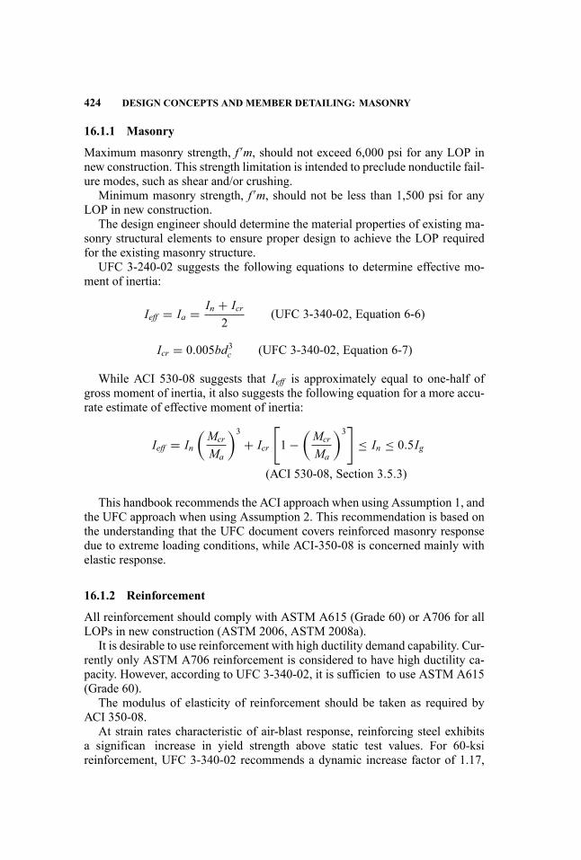
424 DESIGN CONCEPTS AND MEMBER DETAILING: MASONRY
16.1.1 Masonry
Maximum masonry strength, f ′m, should not exceed 6,000 psi for any LOP innew construction. This strength limitation is intended to preclude nonductile fail-ure modes, such as shear and/or crushing.
Minimum masonry strength, f ′m, should not be less than 1,500 psi for anyLOP in new construction.
The design engineer should determine the material properties of existing ma-sonry structural elements to ensure proper design to achieve the LOP requiredfor the existing masonry structure.
UFC 3-240-02 suggests the following equations to determine effective mo-ment of inertia:
Ieff = Ia = In + Icr2
(UFC 3-340-02, Equation 6-6)
Icr = 0.005bd3c (UFC 3-340-02, Equation 6-7)
While ACI 530-08 suggests that Ieff is approximately equal to one-half ofgross moment of inertia, it also suggests the following equation for a more accu-rate estimate of effective moment of inertia:
Ieff = In(Mcr
Ma
)3
+ Icr
[1−
(Mcr
Ma
)3]
≤ In ≤ 0.5Ig
(ACI 530-08, Section 3.5.3)
This handbook recommends the ACI approach when using Assumption 1, andthe UFC approach when using Assumption 2. This recommendation is based onthe understanding that the UFC document covers reinforced masonry responsedue to extreme loading conditions, while ACI-350-08 is concerned mainly withelastic response.
16.1.2 Reinforcement
All reinforcement should comply with ASTM A615 (Grade 60) or A706 for allLOPs in new construction (ASTM 2006, ASTM 2008a).
It is desirable to use reinforcement with high ductility demand capability. Cur-rently only ASTM A706 reinforcement is considered to have high ductility ca-pacity. However, according to UFC 3-340-02, it is sufficien to use ASTM A615(Grade 60).
The modulus of elasticity of reinforcement should be taken as required byACI 350-08.
At strain rates characteristic of air-blast response, reinforcing steel exhibitsa significan increase in yield strength above static test values. For 60-ksireinforcement, UFC 3-340-02 recommends a dynamic increase factor of 1.17,
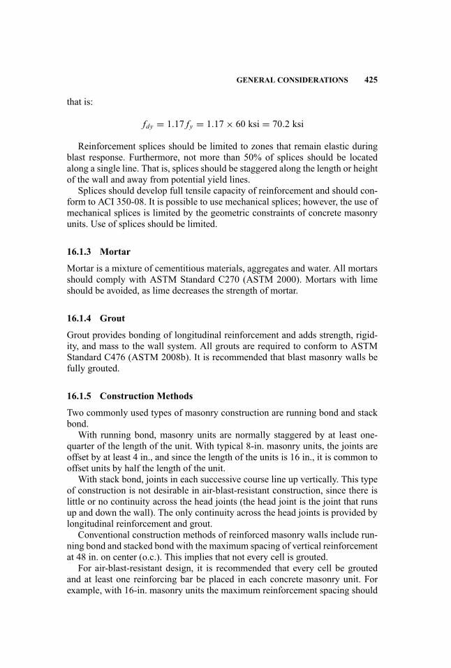
GENERAL CONSIDERATIONS 425
that is:
fdy = 1.17 fy = 1.17× 60 ksi = 70.2 ksi
Reinforcement splices should be limited to zones that remain elastic duringblast response. Furthermore, not more than 50% of splices should be locatedalong a single line. That is, splices should be staggered along the length or heightof the wall and away from potential yield lines.
Splices should develop full tensile capacity of reinforcement and should con-form to ACI 350-08. It is possible to use mechanical splices; however, the use ofmechanical splices is limited by the geometric constraints of concrete masonryunits. Use of splices should be limited.
16.1.3 Mortar
Mortar is a mixture of cementitious materials, aggregates and water. All mortarsshould comply with ASTM Standard C270 (ASTM 2000). Mortars with limeshould be avoided, as lime decreases the strength of mortar.
16.1.4 Grout
Grout provides bonding of longitudinal reinforcement and adds strength, rigid-ity, and mass to the wall system. All grouts are required to conform to ASTMStandard C476 (ASTM 2008b). It is recommended that blast masonry walls befully grouted.
16.1.5 Construction Methods
Two commonly used types of masonry construction are running bond and stackbond.
With running bond, masonry units are normally staggered by at least one-quarter of the length of the unit. With typical 8-in. masonry units, the joints areoffset by at least 4 in., and since the length of the units is 16 in., it is common tooffset units by half the length of the unit.
With stack bond, joints in each successive course line up vertically. This typeof construction is not desirable in air-blast-resistant construction, since there islittle or no continuity across the head joints (the head joint is the joint that runsup and down the wall). The only continuity across the head joints is provided bylongitudinal reinforcement and grout.
Conventional construction methods of reinforced masonry walls include run-ning bond and stacked bond with the maximum spacing of vertical reinforcementat 48 in. on center (o.c.). This implies that not every cell is grouted.
For air-blast-resistant design, it is recommended that every cell be groutedand at least one reinforcing bar be placed in each concrete masonry unit. Forexample, with 16-in. masonry units the maximum reinforcement spacing should
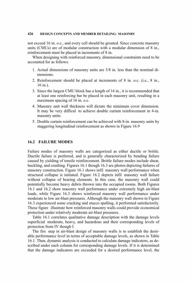
426 DESIGN CONCEPTS AND MEMBER DETAILING: MASONRY
not exceed 16 in. o.c., and every cell should be grouted. Since concrete masonryunits (CMUs) are of modular construction with a modular dimension of 8 in.,reinforcement must be placed in increments of 8 in.
When designing with reinforced masonry, dimensional constraints need to beaccounted for as follows:
1. Actual dimensions of masonry units are 3/8 in. less than the nominal di-mensions.
2. Reinforcement should be placed at increments of 8 in. o.c. (i.e., 8 in.,16 in.).
3. Since the largest CMU block has a length of 16 in., it is recommended thatat least one reinforcing bar be placed in each masonry unit, resulting in amaximum spacing of 16 in. o.c.
4. Masonry unit wall thickness will dictate the minimum cover dimension.It may be very difficul to achieve double curtain reinforcement in 4-in.masonry units.
5. Double curtain reinforcement can be achieved with 8-in. masonry units bystaggering longitudinal reinforcement as shown in Figure 16.9
16.2 FAILURE MODES
Failure modes of masonry walls are categorized as either ductile or brittle.Ductile failure is preferred, and is generally characterized by bending failurecaused by yielding of tensile reinforcement. Brittle failure modes include shear,buckling, and crushing. Figures 16.1 though 16.3 are photos depicting failures ofmasonry construction. Figure 16.1 shows infil masonry wall performance whenstructural collapse is initiated. Figure 16.2 depicts infil masonry wall failurewithout collapse of bearing elements. In this case, the masonry wall couldpotentially become heavy debris thrown into the occupied rooms. Both Figures16.1 and 16.2 show masonry wall performance under extremely high air-blastloads, while Figure 16.3 shows reinforced masonry wall performance undermoderate to low air-blast pressures. Although the masonry wall shown in Figure16.3 experienced some cracking and stucco spalling, it performed satisfactorily.These figure illustrate how reinforced masonry walls could provide economicalprotection under relatively moderate air-blast pressures.
Table 16.1 correlates qualitative damage description with the damage levelssuperficial moderate, heavy, and hazardous and their corresponding levels ofprotection from IV though I.
The firs step in air-blast design of masonry walls is to establish the desir-able performance level in terms of acceptable damage levels, as shown in Table16.1. Then, dynamic analysis is conducted to calculate damage indicators, as de-scribed under each column for corresponding damage levels. If it is determinedthat the damage indicators are exceeded for a desired performance level, the
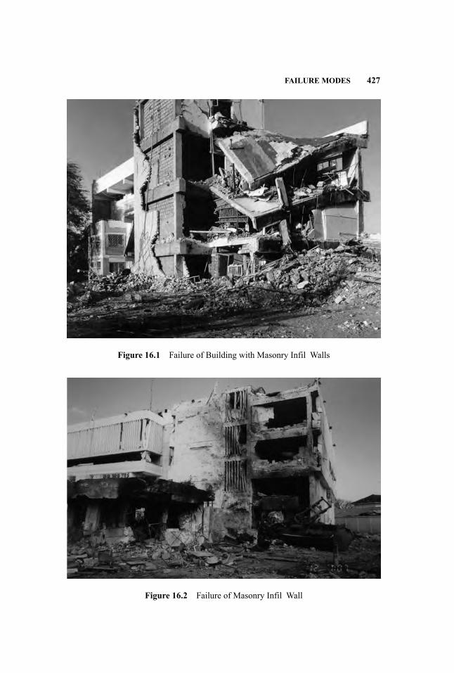
FAILURE MODES 427
Figure 16.1 Failure of Building with Masonry Infil Walls
Figure 16.2 Failure of Masonry Infil Wall
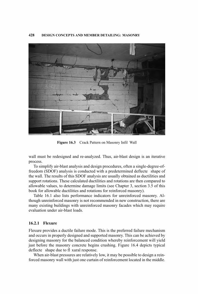
428 DESIGN CONCEPTS AND MEMBER DETAILING: MASONRY
Figure 16.3 Crack Pattern on Masonry Infil Wall
wall must be redesigned and re-analyzed. Thus, air-blast design is an iterativeprocess.
To simplify air-blast analysis and design procedures, often a single-degree-of-freedom (SDOF) analysis is conducted with a predetermined deflecte shape ofthe wall. The results of this SDOF analysis are usually obtained as ductilities andsupport rotations. These calculated ductilities and rotations are then compared toallowable values, to determine damage limits (see Chapter 3, section 3.5 of thisbook for allowable ductilities and rotations for reinforced masonry).
Table 16.1 also lists performance indicators for unreinforced masonry. Al-though unreinforced masonry is not recommended in new construction, there aremany existing buildings with unreinforced masonry facades which may requireevaluation under air-blast loads.
16.2.1 Flexure
Flexure provides a ductile failure mode. This is the preferred failure mechanismand occurs in properly designed and supported masonry. This can be achieved bydesigning masonry for the balanced condition whereby reinforcement will yieldjust before the masonry concrete begins crushing. Figure 16.4 depicts typicaldeflecte shape due to fl xural response.
When air-blast pressures are relatively low, it may be possible to design a rein-forced masonry wall with just one curtain of reinforcement located in the middle.
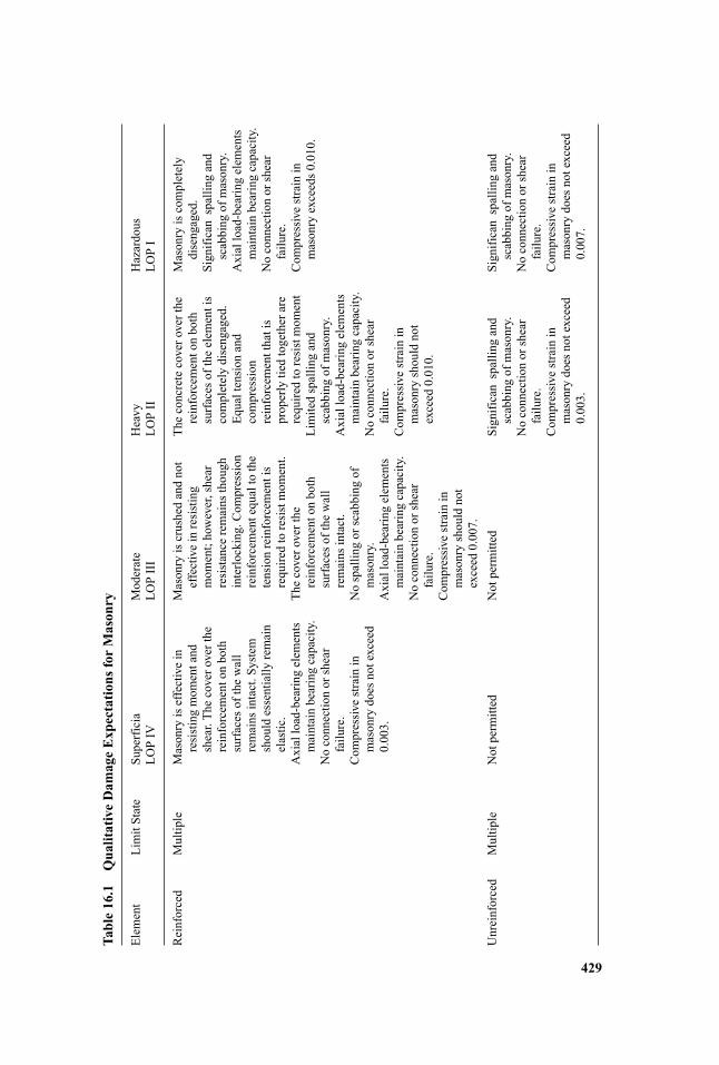
Table16.1
QualitativeDam
ageExpectations
forMasonry
Elem
ent
LimitState
Superficia
Moderate
Heavy
Hazardous
LOPIV
LOPIII
LOPII
LOPI
Reinforced
Multiple
Masonryiseffectivein
resistingmom
entand
shear.Thecoveroverthe
reinforcem
entonboth
surfaceso
fthe
wall
remains
intact.System
shouldessentially
remain
elastic.
Axialload-bearingelem
ents
maintainbearingcapacity.
Noconnectionorshear
failure.
Com
pressivestrainin
masonrydoesnotexceed
0.003.
Masonryiscrushedandnot
effectiveinresisting
mom
ent;however,shear
resistance
remains
though
interlocking.Com
pression
reinforcem
entequaltothe
tensionreinforcem
entis
requiredtoresistmom
ent.
Thecoveroverthe
reinforcem
entonboth
surfaceso
fthe
wall
remains
intact.
Nospallingorscabbing
ofmasonry.
Axialload-bearingelem
ents
maintainbearingcapacity.
Noconnectionorshear
failure.
Com
pressivestrainin
masonryshouldnot
exceed
0.007.
Theconcretecoveroverthe
reinforcem
entonboth
surfaceso
fthe
elem
entis
completelydisengaged.
Equaltension
and
compression
reinforcem
entthatis
properlytiedtogetherare
requiredtoresistmom
ent
Limitedspallingand
scabbing
ofmasonry.
Axialload-bearingelem
ents
maintainbearingcapacity.
Noconnectionorshear
failure.
Com
pressivestrainin
masonryshouldnot
exceed
0.010.
Masonryiscompletely
disengaged.
Significanspallingand
scabbing
ofmasonry.
Axialload-bearingelem
ents
maintainbearingcapacity.
Noconnectionorshear
failure.
Com
pressivestrainin
masonryexceeds0
.010.
Unreinforced
Multiple
Notpermitted
Notpermitted
Significanspallingand
scabbing
ofmasonry.
Noconnectionorshear
failure.
Com
pressivestrainin
masonrydoesnotexceed
0.003.
Significanspallingand
scabbing
ofmasonry.
Noconnectionorshear
failure.
Com
pressivestrainin
masonrydoesnotexceed
0.007.
429
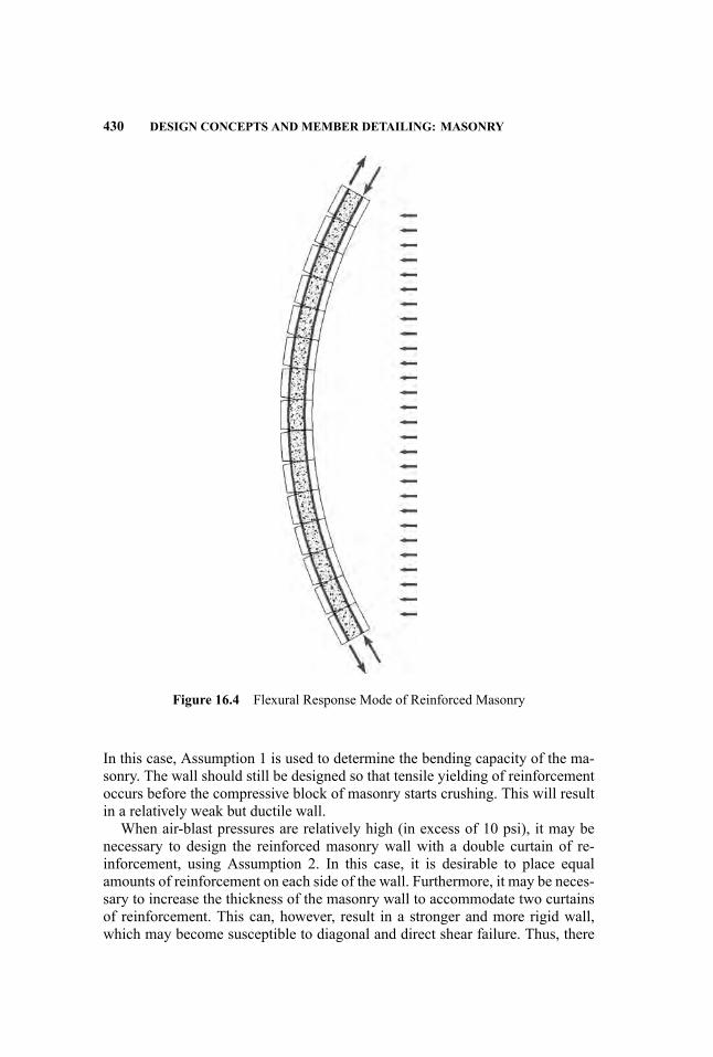
430 DESIGN CONCEPTS AND MEMBER DETAILING: MASONRY
Figure 16.4 Flexural Response Mode of Reinforced Masonry
In this case, Assumption 1 is used to determine the bending capacity of the ma-sonry. The wall should still be designed so that tensile yielding of reinforcementoccurs before the compressive block of masonry starts crushing. This will resultin a relatively weak but ductile wall.
When air-blast pressures are relatively high (in excess of 10 psi), it may benecessary to design the reinforced masonry wall with a double curtain of re-inforcement, using Assumption 2. In this case, it is desirable to place equalamounts of reinforcement on each side of the wall. Furthermore, it may be neces-sary to increase the thickness of the masonry wall to accommodate two curtainsof reinforcement. This can, however, result in a stronger and more rigid wall,which may become susceptible to diagonal and direct shear failure. Thus, there
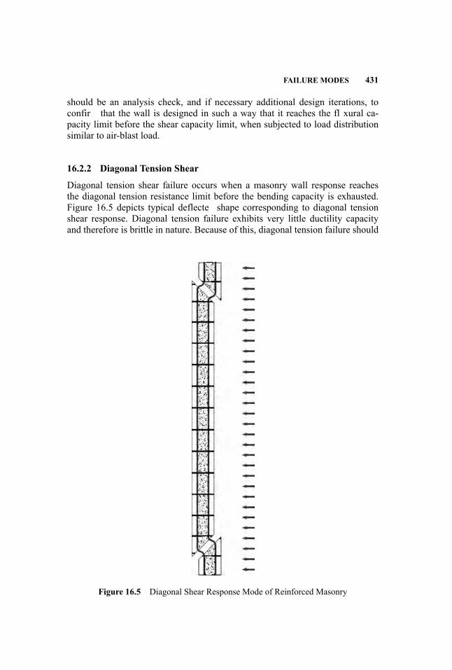
FAILURE MODES 431
should be an analysis check, and if necessary additional design iterations, toconfir that the wall is designed in such a way that it reaches the fl xural ca-pacity limit before the shear capacity limit, when subjected to load distributionsimilar to air-blast load.
16.2.2 Diagonal Tension Shear
Diagonal tension shear failure occurs when a masonry wall response reachesthe diagonal tension resistance limit before the bending capacity is exhausted.Figure 16.5 depicts typical deflecte shape corresponding to diagonal tensionshear response. Diagonal tension failure exhibits very little ductility capacityand therefore is brittle in nature. Because of this, diagonal tension failure should
Figure 16.5 Diagonal Shear Response Mode of Reinforced Masonry

432 DESIGN CONCEPTS AND MEMBER DETAILING: MASONRY
be avoided in blast-resistant masonry walls. One method to avoid diagonal ten-sion failure mode is to decrease the fl xural capacity of the wall in such a waythat the wall undergoes fl xural yielding before shear capacity is exhausted.However, the fl xural resistance of the wall should not be reduced when do-ing so will compromise the desired level of protection. Alternatively, the diag-onal tension capacity of the masonry wall can be increased by increasing thethickness of the masonry, by grouting more cells, or by placing shear reinforce-ment. Placement of shear reinforcement is feasible only with two curtains ofreinforcement. If shear reinforcement is required, it should be placed in such away that it crosses expected diagonal shear crack between the two curtains ofreinforcement.
Diagonal tension capacity for out-of-plane bending of reinforced masonrywalls can be assessed using ACI-350-08 strength design procedures.
16.2.3 Direct Shear
Direct shear occurs when explosion occurs very close to the wall and when mor-tar joints are too weak to provide shear stress fl w continuity across the masonryunits. Figure 16.6 depicts typical deflecte shape consistent with diagonal shearresponse. Direct shear may be of concern when scaled distance is less then 4. Atthis standoff it is expected that air-blast pressures will be of very high magnitudeand extremely short duration. If the air-blast pressures are of extremely short du-ration, there will be no time for the masonry wall to respond in fl xure mode,and direct shear response will dominate.
Direct shear capacity depends on friction resistance across the mortar jointand dowel action of the longitudinal reinforcement. Direction shear strength gen-erally exceeds diagonal shear strength. The direct shear failure mode is almostalways very brittle and should be avoided. One way to avoid direct shear failureis to increase the standoff between the masonry wall and the expected explosionsource. Furthermore, since reinforced masonry walls do not perform well underextremely high air-blast pressures, direct shear failure modes should be avoidedwhenever possible.
16.2.4 Breach and Spall Phenomena
Breach occurs when a weapon is placed directly against or very close to themasonry wall surface. Detonation at this close proximity causes shattering ofthe masonry units. Breach analysis is often conducted using computational fluidynamic codes with appropriate equations of state, or by experimental studies.Breach effects can be mitigated by masonry wall thickness, proper confinementand application of anti-spall laminates such as fibe -reinforced polymer (FRP).
Spall typically occurs on the back side of the wall when a weapon isplaced at the breaching distance but does not cause full breach. Spall occursdue to a compression wave traveling through the thickness of the masonry.
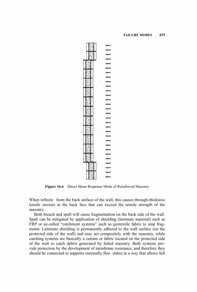
FAILURE MODES 433
Figure 16.6 Direct Shear Response Mode of Reinforced Masonry
When reflecte from the back surface of the wall, this causes through-thicknesstensile stresses at the back face that can exceed the tensile strength of themasonry.
Both breach and spall will cause fragmentation on the back side of the wall.Spall can be mitigated by application of shielding (laminate material) such asFRP or so-called “catchment systems” such as geotextile fabric to stop frag-ments. Laminate shielding is permanently adhered to the wall surface (on theprotected side of the wall) and may act compositely with the masonry, whilecatching systems are basically a curtain or fabric located on the protected sideof the wall to catch debris generated by failed masonry. Both systems pro-vide protection by the development of membrane resistance, and therefore theyshould be connected to supports (normally floo slabs) in a way that allows full
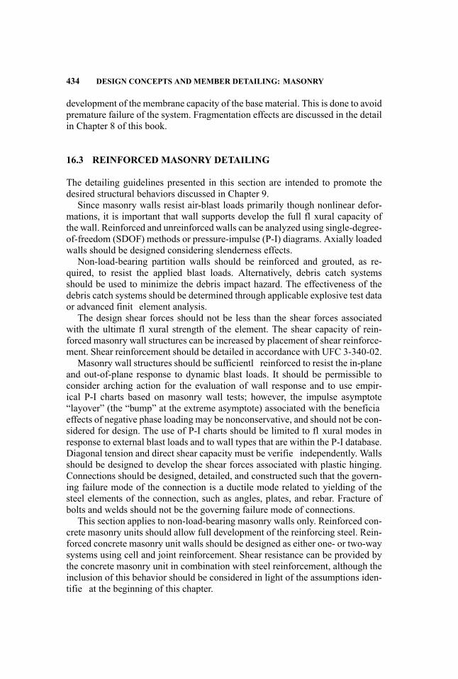
434 DESIGN CONCEPTS AND MEMBER DETAILING: MASONRY
development of the membrane capacity of the base material. This is done to avoidpremature failure of the system. Fragmentation effects are discussed in the detailin Chapter 8 of this book.
16.3 REINFORCED MASONRY DETAILING
The detailing guidelines presented in this section are intended to promote thedesired structural behaviors discussed in Chapter 9.
Since masonry walls resist air-blast loads primarily though nonlinear defor-mations, it is important that wall supports develop the full fl xural capacity ofthe wall. Reinforced and unreinforced walls can be analyzed using single-degree-of-freedom (SDOF) methods or pressure-impulse (P-I) diagrams. Axially loadedwalls should be designed considering slenderness effects.
Non-load-bearing partition walls should be reinforced and grouted, as re-quired, to resist the applied blast loads. Alternatively, debris catch systemsshould be used to minimize the debris impact hazard. The effectiveness of thedebris catch systems should be determined through applicable explosive test dataor advanced finit element analysis.
The design shear forces should not be less than the shear forces associatedwith the ultimate fl xural strength of the element. The shear capacity of rein-forced masonry wall structures can be increased by placement of shear reinforce-ment. Shear reinforcement should be detailed in accordance with UFC 3-340-02.
Masonry wall structures should be sufficientl reinforced to resist the in-planeand out-of-plane response to dynamic blast loads. It should be permissible toconsider arching action for the evaluation of wall response and to use empir-ical P-I charts based on masonry wall tests; however, the impulse asymptote“layover” (the “bump” at the extreme asymptote) associated with the beneficiaeffects of negative phase loading may be nonconservative, and should not be con-sidered for design. The use of P-I charts should be limited to fl xural modes inresponse to external blast loads and to wall types that are within the P-I database.Diagonal tension and direct shear capacity must be verifie independently. Wallsshould be designed to develop the shear forces associated with plastic hinging.Connections should be designed, detailed, and constructed such that the govern-ing failure mode of the connection is a ductile mode related to yielding of thesteel elements of the connection, such as angles, plates, and rebar. Fracture ofbolts and welds should not be the governing failure mode of connections.
This section applies to non-load-bearing masonry walls only. Reinforced con-crete masonry units should allow full development of the reinforcing steel. Rein-forced concrete masonry unit walls should be designed as either one- or two-waysystems using cell and joint reinforcement. Shear resistance can be provided bythe concrete masonry unit in combination with steel reinforcement, although theinclusion of this behavior should be considered in light of the assumptions iden-tifie at the beginning of this chapter.

REINFORCED MASONRY DETAILING 435
16.3.1 General
All concrete masonry units should be fully grouted for LOP III and LOP IV.All lap splices should be tension lap splices, as specifie in ACI 530 and ACI
530.1 (American Concrete Institute 2008).Use of mechanical splices should be limited to zones that remain elastic dur-
ing blast response, unless the mechanical splices can be shown to develop theexpected tensile strength of the bar under conditions generated by blast loads.All mechanical splices should meet or exceed the specification in ACI 530 andACI 530.1.
Use of welded splices should be limited to zones that remain elastic duringblast response, unless the welded splices can be shown to develop the expectedtensile strength of the bar under conditions generated by blast loads. All weldedsplices should meet or exceed the specification in ACI 530 and ACI 530.1.
16.3.2 Longitudinal Reinforcement
For air-blast-resistant design, it is desirable to place longitudinal reinforce-ment in each cell in fully grouted concrete masonry units. This will result inreinforcement placed at 8 in. o.c. This detailing approach is beneficia since ev-ery grouted cell adds weight, rigidity, and shear strength, and closely spaced barsmay reduce the size of fragments should the wall fail under air-blast loads. Fig-ures 16.7 though 16.10 provide sample detailing options for reinforced masonry.
16.3.3 Horizontal Reinforcement
A bond beam course with two horizontal reinforcing bars should be placed allaround the cap course of the wall. Bars should be spliced and the course grouted,per requirements of ACI 530.
All new construction should have a bond beam course with a minimum of twohorizontal reinforcing bars. Reinforcing bars should be located at the level of thelowest attachment of the masonry wall to the floo diaphragm. Bond beam shouldbe placed at any horizontal diaphragm or floo system supported by the wall. Ifthe attachment band in the diaphragm is thicker than the bond beam course, thenthe bond beam course should be placed on the bottom of the diaphragm, andall cells in courses to the top of the attachment band should be fully grouted.Bars should be spliced and the course grouted per requirements of ACI 530. SeeFigure 16.11 for examples of bond beam reinforcement.
A bond beam course with two horizontal reinforcing bars should be placedat all lintel locations; the bar should be either hooked around vertical reinforce-ment on either side of the opening or continuous along the wall, with the coursegrouted per requirements of ACI 530.
Control joints for all LOPs should be designed, at a minimum, with onevertical bar in a fully grouted cell column on each side of the control joint.
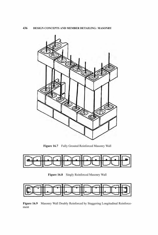
436 DESIGN CONCEPTS AND MEMBER DETAILING: MASONRY
Figure 16.7 Fully Grouted Reinforced Masonry Wall
Figure 16.8 Singly Reinforced Masonry Wall
Figure 16.9 Masonry Wall Doubly Reinforced by Staggering Longitudinal Reinforce-ment
REINFORCED MASONRY DETAILING 437
Figure 16.10 Doubly Reinforced Masonry Wall – Two Bars per Each Cell
(a)
(b)
Figure 16.11 Examples of Bond Beam
438 DESIGN CONCEPTS AND MEMBER DETAILING: MASONRY
Code-approved control joint block and expansion material systems should beused as necessary in all blast-resistant masonry systems.
The design professional should determine the appropriate locations for controljoints, to the extent that their locations impact blast resistance.
The design professional should specify continuity and/or end conditions ofhorizontal bars and bond beams at control joints.
16.3.4 Walls
All elements constructed to LOPs I and II should have at least one continuousvertical reinforcing bar in a fully grouted cell column, with spacing not to exceed48 in. o.c.
All elements constructed to LOP III and IV should have at least one continu-ous vertical reinforcing bar per block in a fully grouted cell column, with spacingnot to exceed 16 in. oc.
In addition, at least one vertical bar should be placed in a fully grouted cellcolumn at all inside or outside corners, alongside any openings, and in the cellcolumn on each side of control joints, if they are used in the structure
All elements constructed to LOP III and IV should have a minimum verticalreinforcement ratio of 0.0025.
Bearing Walls Bearing walls are subjected to constant axial load in addition toblast loading. The presence of axial load in reinforced masonry increases bendingcapacity up to a so-called balanced point on a P/M diagram, after which axialload causes rapid deterioration of bearing wall air-blast-resistance capacity, dueto buckling. Additionally, the presence of axial load induces larger stresses onblock masonry under compression, and may cause the masonry wall to fail inconcrete crushing mode rather than through the yielding of the reinforcement(i.e., compression-controlled section).
Careful attention must be paid during the structural analysis of bearing wallsto avoid these undesirable failure modes (crushing and buckling).
Slender Walls Slender walls normally carry some axial load, which affects theoverall resistance of the wall and should be accounted for in the analysis. Allslender wall design should follow ACI 350-08, Section 3.3.5
Infil Walls Infil masonry walls typically act as partitions and are supported byfloo slabs or beams. If properly designed they can provide physical separationand protection against air-blast waves and fragments.
16.3.5 Support Connections
Since masonry walls are primary blast-load-resisting systems, and since masonrywalls are normally expected to respond to air-blast load in nonlinear regime,

UNREINFORCED MASONRY 439
it is necessary to provide sufficien support to allow masonry walls to developfull plastic mechanism. This can be achieved by fully developing longitudinalreinforcement into the supports.
16.4 UNREINFORCED MASONRY
Unreinforced masonry, due to its brittle nature, is not recommended in new con-struction. However, there is a vast amount of unreinforced masonry in existingand historic structures. Sometimes, existing reinforced masonry walls containreinforcement that provides negligible improvement over the unreinforced ma-sonry. Lightly reinforced masonry walls of this type are usually analyzed usingthe principles of unreinforced masonry discussed in this section.
Methods have been established for assessing the stability of unreinforced ma-sonry walls under blast loading. The phenomenon of arching action is one of theprimary mechanisms by which unreinforced masonry resists complete failure.However, even slight in-plane vertical movements of “rigid” supports negate thelarge benefit predicted by the assumed arching action.
16.4.1 Performance Evaluation
When an external explosion imposes an air-blast load on a heavy external wallsystem, the air-blast pressure must overcome the inertial forces of the wall it-self before putting the system into motion and causing damage. In the case ofthick, unreinforced masonry walls, these forces are very large, and therefore theresulting damage is less than one might intuitively imagine.
Informative data for masonry can be obtained from the Concrete MasonryUnit Database Software (CMUDS) program. The full-scale equivalent dimen-sions for the data have spans of 8 to 11 feet and thicknesses of 6 to 8 inches.CMUDS also provides data on reinforced masonry, with reinforcement ratiosranging from 0.15% to 00%, although most of the data have reinforcing ra-tios from 0.15% to 0.30%. The data include full-scale shock tube testing andhigh explosives testing on full- and quarter-scale walls. Elastic-perfectly plas-tic analysis should not be used for unreinforced masonry elements, as this willlead to a nonconservative calculation of the blast load that such elements canresist.
Wall Analysis A common configuratio for windows in historic unreinforcedmasonry buildings, especially those constructed in the late 1800s and the early1900s, is to have two or three windows per structural bay. This creates masonrypiers between individual window openings. These piers tend to be critical wall-support elements.
It is best to begin calculations assuming that the windows can be anchoredto the walls at all four sides, distributing the forces from the windows to the
440 DESIGN CONCEPTS AND MEMBER DETAILING: MASONRY
supporting walls at the head, sill, and jambs. Walls should have sufficien dy-namic capacity to allow window glazing to break first This approach, commonlyknown as balanced design, has been shown to reduce the weight (the size and theamount) of debris that may enter the occupied space. There is a direct correlationbetween injuries and size and velocity of debris.
Two computational models for analyzing wall response are described below.
Simply-Supported Wall A conservative approach to modeling the resistance ofan unreinforced masonry wall for an air-blast load is to represent the wall as aslender member subjected to a uniformly applied dynamic load. It is assumedthat there is no contribution of axial compressive forces at the top and bottomof the wall, and the wall is analyzed as a simply-supported beam. The fl xu-ral resistance of the wall is dependent on the compressive stresses from its selfweight, and the tensile strength as define by the mortar’s modulus of rupture.Because unreinforced masonry has little tensile resistance, the fl xural capacityof the wall is minimal, resulting in extensive cracking and brittle failure at theinterior face of the wall.
Rigid Supports Another model, based on UFC 3-340-02 (the recognizedair-blast-resistance design manual throughout the United States), assumesthat the top and bottom supports are completely rigid and provide restraintagainst elongation. Strength comes from compressive blocks that form at thetop, bottom, and mid-height hinge locations of the wall, behavior known as acompressive membrane phenomenon. This model also assumes that the mortarjoints will be cracked, disregarding what little fl xural tensile strength remainsin the masonry. The deflecte wall “wedges” itself between floo slabs and alsoforms a plastic hinge at mid-height. This model takes into account that masonryinfil walls will often have a gap at the top, either from a mortar joint or from adesign that accounts for fl xure of the floo systems above.
16.4.2 Retrofi Recommendations
Retrofi masonry walls can be costly, but may be unavoidable due to variousconstraints such as the historic value of a building. Masonry wall retrofit areusually required when an existing wall cannot be replaced and does not meet thedesired performance level of protection. Retrofi recommendations provided inthis section apply equally to unreinforced and reinforced masonry walls.
Catchment Systems Or Curtains Depending on the performance intent, an al-ternative to structural retrofi of unreinforced masonry walls is to design geotex-tile fabric blast curtain located on the inside face of a non-blast-mitigating ma-sonry wall. This curtain will provide protection from masonry fragments. Thegeotextile fabric and connections should be designed for membrane action of thefabric. The fabric connections should transfer loads into the floo system without
UNREINFORCED MASONRY 441
causing fabric tears from stress concentrations. The performance of a specifiegeotextile fabric and its connections should be verifie by blast testing. Gener-ally, blast testing, in addition to demonstrating acceptable performance for designloads, should also demonstrate the post-failure behavior of the retrofi system, toensure that the failure of the system does not create brittle and hazardous failure.
Secondary Walls A secondary blast-mitigating wall system installed on theinside face of an existing wall system, in addition to being designed to withstandfragmentation and impact effects (due to the frangible wall in front), should alsobe designed as a new wall, in accordance with this chapter.
Steel Supporting Frames The most straightforward retrofi is to install steelframes, interior to the existing walls, that support the wall and the window sys-tem. This solution is appropriate where the wall piers are not able to support theadditional air-blast load imposed by the windows. This retrofi is often unaccept-able to architects, as it either creates an uneven wall surface or requires reducingthe overall room size by furring out the walls.
Shotcrete Walls In some cases, other loading condition requirements may becombined with air-blast requirements to develop multipurpose solutions. Whereprogressive collapse or seismic design requirements would benefi from shotcretewalls, this may be used as an air-blast retrofi of unreinforced masonry walls aswell. Window systems could be mounted in the new concrete wall system. Thiswould be an especially useful technique for relatively larger blast loads.
Fiber-Reinforced Polymer (FRP) Another retrofi method is to apply ver-tical FRP composite strips along the inside face of the masonry wall. FRPcomposites have significan tensile strength in the direction of the fiber andcan be highly effective in increasing the wall’s out-of-plane fl xural capac-ity. Additional advantages of this method are that it is relatively unobtrusiveto the architectural detailing of the wall and existing structure, and its ap-plication process is not labor-intensive, requiring little disruption to buildingoccupants.
The fl xural capacity of an FRP-retrofitte unreinforced masonry wall canbe assessed using basic moment-equilibrium relations, as with a steel-reinforcedmasonry wall. The tensile strength of the masonry is disregarded, and all tensileresistance is assumed to be provided by the FRP. The fl xural resistance canthen be computed as a function of the compressive strength of the masonry, thetensile strength of the FRP, the thickness of the masonry panel, and the value ofthe applied axial force.
Blast tests have demonstrated that it is unlikely that the wall’s predominantfailure mode will be failure of the FRP. Also, tests of unreinforced masonryunits to out-of-plane air-blast loading have demonstrated that shear failure at thesupports is a predominant failure mechanism. The FRP reinforcing provides no
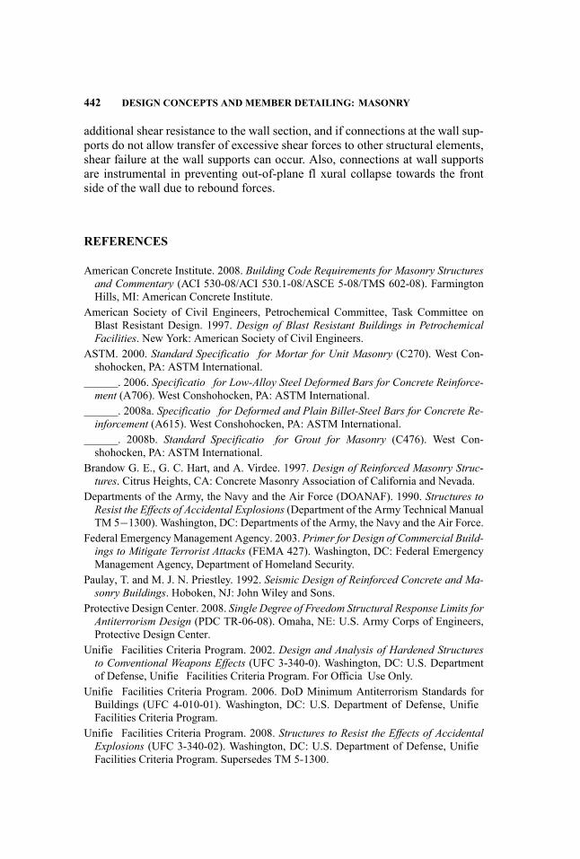
442 DESIGN CONCEPTS AND MEMBER DETAILING: MASONRY
additional shear resistance to the wall section, and if connections at the wall sup-ports do not allow transfer of excessive shear forces to other structural elements,shear failure at the wall supports can occur. Also, connections at wall supportsare instrumental in preventing out-of-plane fl xural collapse towards the frontside of the wall due to rebound forces.
REFERENCES
American Concrete Institute. 2008. Building Code Requirements for Masonry Structuresand Commentary (ACI 530-08/ACI 530.1-08/ASCE 5-08/TMS 602-08). FarmingtonHills, MI: American Concrete Institute.
American Society of Civil Engineers, Petrochemical Committee, Task Committee onBlast Resistant Design. 1997. Design of Blast Resistant Buildings in PetrochemicalFacilities. New York: American Society of Civil Engineers.
ASTM. 2000. Standard Specificatio for Mortar for Unit Masonry (C270). West Con-shohocken, PA: ASTM International.
. 2006. Specificatio for Low-Alloy Steel Deformed Bars for Concrete Reinforce-ment (A706). West Conshohocken, PA: ASTM International.
. 2008a. Specificatio for Deformed and Plain Billet-Steel Bars for Concrete Re-inforcement (A615). West Conshohocken, PA: ASTM International.
. 2008b. Standard Specificatio for Grout for Masonry (C476). West Con-shohocken, PA: ASTM International.
Brandow G. E., G. C. Hart, and A. Virdee. 1997. Design of Reinforced Masonry Struc-tures. Citrus Heights, CA: Concrete Masonry Association of California and Nevada.
Departments of the Army, the Navy and the Air Force (DOANAF). 1990. Structures toResist the Effects of Accidental Explosions (Department of the Army Technical ManualTM 5−1300). Washington, DC: Departments of the Army, the Navy and the Air Force.
Federal EmergencyManagement Agency. 2003. Primer for Design of Commercial Build-ings to Mitigate Terrorist Attacks (FEMA 427). Washington, DC: Federal EmergencyManagement Agency, Department of Homeland Security.
Paulay, T. and M. J. N. Priestley. 1992. Seismic Design of Reinforced Concrete and Ma-sonry Buildings. Hoboken, NJ: John Wiley and Sons.
Protective Design Center. 2008. Single Degree of Freedom Structural Response Limits forAntiterrorism Design (PDC TR-06-08). Omaha, NE: U.S. Army Corps of Engineers,Protective Design Center.
Unifie Facilities Criteria Program. 2002. Design and Analysis of Hardened Structuresto Conventional Weapons Effects (UFC 3-340-0). Washington, DC: U.S. Departmentof Defense, Unifie Facilities Criteria Program. For Officia Use Only.
Unifie Facilities Criteria Program. 2006. DoD Minimum Antiterrorism Standards forBuildings (UFC 4-010-01). Washington, DC: U.S. Department of Defense, UnifieFacilities Criteria Program.
Unifie Facilities Criteria Program. 2008. Structures to Resist the Effects of AccidentalExplosions (UFC 3-340-02). Washington, DC: U.S. Department of Defense, UnifieFacilities Criteria Program. Supersedes TM 5-1300.

UNREINFORCED MASONRY 443
U.S. Army Corps of Engineers. 1999. Airblast Protection Retrofi for UnreinforcedConcrete Masonry Walls (ETL 1110-3-494). Washington, DC: U.S. Army Corps ofEngineers.
U.S. Department of State, Overseas Buildings Operations. 2002. A&E Design Guidelinesfor U.S. Diplomatic Mission Buildings. Washington, DC: U.S. Department of State,Overseas Building Operations.

17 Retrofi of StructuralComponents and Systems
John E. Crawford and L. Javier Malvar
17.1 INTRODUCTION
Structural components such as columns, beams, floors and walls are likely to bevulnerable to blast loads. This is important because the resulting damage to thesecomponents could produce partial or complete collapse of the structural system,or produce large volumes of injurious debris. For example:
� The blast at the Alfred P. Murrah Federal Building in Oklahoma City ledto the shearing of main load-bearing columns and resulted in the collapseof nearly half of the building’s structure, which resulted in a large numberof casualties. In this incident, it was estimated that 87% of the people inthe collapsed portion died (153 out of 175), whereas only 5% of the peoplein the uncollapsed portion died (10 out of 186) (Federal Emergency Man-agement Agency 1996), indicating that, had the structure better resisted theblast loads and not experienced a collapse, the casualties would have beena lot fewer.
� Even when the structural system survives, blast loads can cause the dis-integration of walls and windows, creating secondary fragments that willgenerate fatalities and injuries in the adjacent rooms.
In this chapter, methods are described for retrofittin structural componentsto enhance their blast resistance and for assessing the protection the retrofitprovide.
Much of this chapter is devoted to describing retrofi techniques to protectreinforced concrete (RC) columns. This was done because so much can be doneto prevent the catastrophic damage observed for some types of RC columns whensubjected to blast. This information, along with that for the other components, ispresented in a summarized form due to space limitation.
445
Handbook for Blast-Resistant Design of Buildings Edited by Donald 0. Dusenberry
Copyright 0 2010 by John Wiley & Sons, Inc. All rights reserved.

446 RETROFIT OF STRUCTURAL COMPONENTS AND SYSTEMS
17.2 RETROFIT OF COLUMNS
Typically, columns are the component whose integrity is key to sustaining thecapability of a building’s structural system to survive a blast load. As such, at-tention to ensuring their survival should have the highest priority when the blastresistance of a building is to be upgraded.
17.2.1 Reinforced Concrete Columns
Soon after the bombing of the Alfred P. Murrah Building, it was shown that high-fidelit physics-based (HFPB) finit element (FE) models would have predictedthe failure of the bearing columns nearest the point of detonation, and the result-ing progressive building collapse (Crawford, Wesevich, et al. 1995; Crawford,Malvar, et al. 1996; Crawford, Bogosian, and Wesevich 1997). These modelsalso suggested that the use of composite wraps, or steel jackets, could have in-creased the columns’ blast resistance sufficientl to prevent their failure, andthus, the building’s collapse.
The concept of jacketing columns had also been suggested by the Fed-eral Emergency Management Agency (Federal Emergency Management Agency1996), which indicated that retrofi techniques used to resist seismic loads couldbe extended to resist blast loads. But it was not until 1999 (Crawford 2001) that,in a series of three blast tests conducted by the Defense Threat Reduction Agency(DTRA), it was demonstrated that steel and fibe -reinforced polymer (FRP) jack-eting could be used to significantl enhance the blast resistance of RC columns.
Test Data These firs three blast tests were conducted on columns located onthe ground floo of a full-scale four-story RC building (Figure 17.1); they aredesignated as Tests 1 to 3 in the figure The same blast load on identical columns(i.e., except for the retrofit was used in all three tests, the results being shown inFigure 17.2.
The Test 1 column’s performance under these conditions is shown in Figure17.2a, where a diagonal shear failure can be observed—which is not surpris-ing, given the relatively wide tie spacing of this conventionally designed col-umn. However, when this type of column design is retrofitte with a steel jacket(Test 2), or carbon FRP (CFRP) hoop wraps and vertical CFRP strips (Test 3),it can survive the same load in nearly pristine condition (Malvar, Morrill, andCrawford 1999).
Based on these initial results, an extensive series of full-scale column compo-nents was tested using various types of FRP retrofi designs. The results from theblast tests were augmented with a companion program of ten laboratory tests ofcolumn specimens identical to those tested by blast, but loaded statically with hy-draulic rams (Figure 17.3). These rams were applied in such a way as to approx-imate the deformation patterns observed in the blast tests. Aramid FRP (AFRP),glass FRP (GFRP), and CFRP composites were used successfully in these tests,although CFRP has shown better durability characteristics (American Concrete

RETROFIT OF COLUMNS 447
Figure 17.1 Location of initial blast tests of unretrofitte and retrofitte RC columns(tests were conducted using a four-story building constructed using a cast-in-place con-ventionally designed RC flat-sla framing system; figur shows structure after Test 1(Photo courtesy of DTRA)
Institute 2002, Malvar 1998a), and its higher stiffness can provide more efficienconfinemen with less material (Malvar, Morrill, and Crawford 2004).
Design/Analysis Tools One of the major outcomes of the test program wasthe development and validation of a procedure for the design of FRP wrap andsteel jackets to retrofi RC columns to enhance their blast resistance. This pro-cedure can quickly assess the performance of both conventional and retrofitteRC columns subjected to blast loads, and it provides an easily used means todesign an FRP wrap or steel jacket to retrofi an RC column so that it can survivea specifi blast threat (Malvar, Morrill, and Crawford 1999; Morrill, Malvar, andCrawford 1999; Morrill, Malvar, and Crawford et al. 2000; Morrill, Malvar, andCrawford et al. 2004; Perea and Morrill 2002; Kersul and Sunshine 2002). Theretrofi design procedure was embodied in the code CBARD (Crawford, Malvar,and Ferritto et al. 2003). For composites, the design procedure determines thenumber of FRP hoop wraps needed (and possible vertical FRP reinforcement)for a given blast load. For steel jackets, it determines the required jacket thick-ness, given the proposed jacket geometry.

448 RETROFIT OF STRUCTURAL COMPONENTS AND SYSTEMS
(a)
(b) (c)
Figure 17.2 Depiction of results from full-scale blast testing of retrofitte and un-retrofitte RC columns (Photo courtesy of DTRA): (a) Unretrofitte column (Test 1),(b) Steel jacket column (Test 2), (c) FRP wrapped column (Test 3).
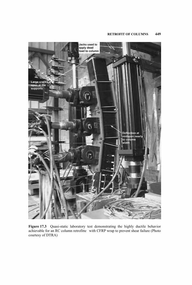
RETROFIT OF COLUMNS 449
Figure 17.3 Quasi-static laboratory test demonstrating the highly ductile behaviorachievable for an RC column retrofitte with CFRP wrap to prevent shear failure (Photocourtesy of DTRA)
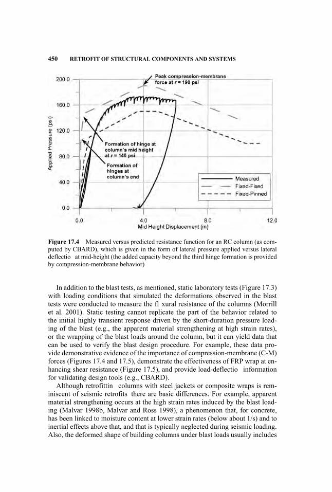
450 RETROFIT OF STRUCTURAL COMPONENTS AND SYSTEMS
Figure 17.4 Measured versus predicted resistance function for an RC column (as com-puted by CBARD), which is given in the form of lateral pressure applied versus lateraldeflectio at mid-height (the added capacity beyond the third hinge formation is providedby compression-membrane behavior)
In addition to the blast tests, as mentioned, static laboratory tests (Figure 17.3)with loading conditions that simulated the deformations observed in the blasttests were conducted to measure the fl xural resistance of the columns (Morrillet al. 2001). Static testing cannot replicate the part of the behavior related tothe initial highly transient response driven by the short-duration pressure load-ing of the blast (e.g., the apparent material strengthening at high strain rates),or the wrapping of the blast loads around the column, but it can yield data thatcan be used to verify the blast design procedure. For example, these data pro-vide demonstrative evidence of the importance of compression-membrane (C-M)forces (Figures 17.4 and 17.5), demonstrate the effectiveness of FRP wrap at en-hancing shear resistance (Figure 17.5), and provide load-deflectio informationfor validating design tools (e.g., CBARD).
Although retrofittin columns with steel jackets or composite wraps is rem-iniscent of seismic retrofits there are basic differences. For example, apparentmaterial strengthening occurs at the high strain rates induced by the blast load-ing (Malvar 1998b, Malvar and Ross 1998), a phenomenon that, for concrete,has been linked to moisture content at lower strain rates (below about 1/s) and toinertial effects above that, and that is typically neglected during seismic loading.Also, the deformed shape of building columns under blast loads usually includes
(a)
(b)
Figure 17.5 Response of conventional and CFRP hoop retrofitte 14-inch square RCcolumns (the axial load in the CFRP column initially increases with increasing lateraldeflectio due to compression membrane then decreases to 100 kips when the test wasstopped): (a) Axial load, (b) Lateral load
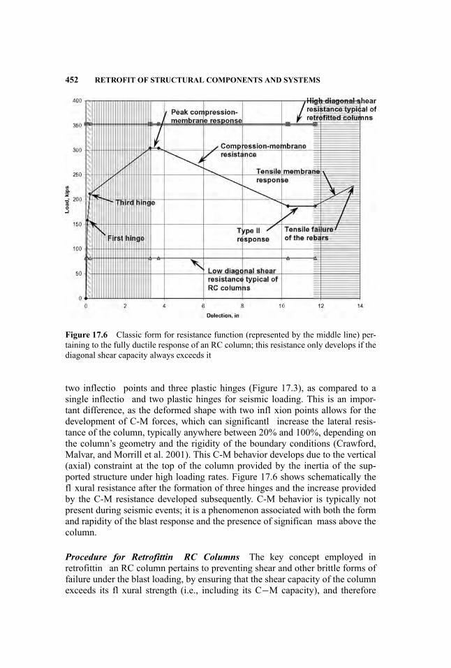
452 RETROFIT OF STRUCTURAL COMPONENTS AND SYSTEMS
Figure 17.6 Classic form for resistance function (represented by the middle line) per-taining to the fully ductile response of an RC column; this resistance only develops if thediagonal shear capacity always exceeds it
two inflectio points and three plastic hinges (Figure 17.3), as compared to asingle inflectio and two plastic hinges for seismic loading. This is an impor-tant difference, as the deformed shape with two infl xion points allows for thedevelopment of C-M forces, which can significantl increase the lateral resis-tance of the column, typically anywhere between 20% and 100%, depending onthe column’s geometry and the rigidity of the boundary conditions (Crawford,Malvar, and Morrill et al. 2001). This C-M behavior develops due to the vertical(axial) constraint at the top of the column provided by the inertia of the sup-ported structure under high loading rates. Figure 17.6 shows schematically thefl xural resistance after the formation of three hinges and the increase providedby the C-M resistance developed subsequently. C-M behavior is typically notpresent during seismic events; it is a phenomenon associated with both the formand rapidity of the blast response and the presence of significan mass above thecolumn.
Procedure for Retrofittin RC Columns The key concept employed inretrofittin an RC column pertains to preventing shear and other brittle forms offailure under the blast loading, by ensuring that the shear capacity of the columnexceeds its fl xural strength (i.e., including its C−M capacity), and therefore
RETROFIT OF COLUMNS 453
ensuring that the column dissipates the most energy possible via fl xure. For ex-ample, in Figure 17.6, if the shear capacity is depicted by the top line (demarkedwith the solid squares), then the complete fl xural behavior will be allowed todevelop. This latter situation ensures that the brittle shear failure response isavoided altogether (i.e., over the whole range of the column’s response), and in-stead ensures a ductile fl xural response up to the point where P-δ failure occurs.When the shear capacity of the column is too low (e.g., if in Figure 17.6 the shearcapacity is represented by the lowest line, demarked by the open triangles), thiscan be remediated by employing steel jackets or composite wraps to shift this lineupward—for example, to the location of the high shear resistance line. In the caseof composites, hoop wraps in general are sufficien to provide the required shearcapacity and ensure ductile behavior, and vertical sheets or strips are not needed.Moreover, vertical composite reinforcements tend to rupture at low column lat-eral displacement, often before compression membrane is developed—that is,at a deflectio of half the column depth, or less; see DSWA (Defense SpecialWeapons Agency 1998) or Malvar and Wesevich (1996)—whereas the hoopwraps can remain intact during large lateral deflection (see Figure 17.3).
Description of Design Methodology. This methodology contains a numberof unique features that distinguishes it from other design procedures, such asthose for retrofittin columns to improve their seismic capacity and traditionalAmerican Concrete Institute (ACI) design. These features include:
� Recognition that some RC columns, even those designed for regions of highseismicity, are prone to fail in shear and/or experience catastrophic loss ofaxial capacity under a blast load.
� Using resistance functions (e.g., as shown in Figure 17.4) specially tailoredto the column’s geometry and the retrofi concepts employed.
� Focusing the retrofi design on achieving a fully ductile response mecha-nism (e.g., as demonstrated in Figure 17.5) for the lateral response of thecolumn. A primary goal in designing the retrofi is to have a column that isfully ductile under lateral load.
� Using a best-estimate response-prediction model for selecting design pa-rameters and estimating capacities of retrofitte and unretrofitte columns.
� Using a single-degree-of-freedom (SDOF) model to predict responses toblast loads for both unretrofitte and retrofitte RC columns.
Blast loads may produce several types of response indicating various deficiencies, or lack thereof, in the column’s behavior. The deficiencie likely to beencountered include:
� Lack of Diagonal Shear Capacity: The column can fail in shear with littleplastic behavior, hence dissipating little energy. This is a worst-case condi-tion for a column subjected to a blast load, and will likely be the predomi-nant reason for retrofittin columns. This deficien y is sometimes referred

454 RETROFIT OF STRUCTURAL COMPONENTS AND SYSTEMS
to, although not preferably, as diagonal tension failure rather than diagonalshear failure.
� Lack of Flexural Ductility: Good practice would dictate that columns shouldachieve a full measure of fl xural ductility for blast-resistant design—a fullmeasure being reaching their deflectio limit, which is related to keepingthe column’s axial demand/capacity ratio less than 1 (one). Deflection as-sociated with this level of ductility (i.e., full measure) are typically on theorder of a large fraction of the column’s width. This may not be practical forwide, short columns, in which case, one must be content with prevention ofshear and other brittle failure modes.
� Lack of Direct Shear Capacity: This condition is uncommon for buildingcolumns. It occurs for columns with high diagonal shear capacity and highfl xural resistance. This condition is of particular concern for columns hav-ing low ratios of height to depth, which is common in parking structuresunderneath multistory buildings, and for columns with steel jackets. It isoften not practical or easy to enhance the direct shear capacity, but significant energy can be dissipated by the direct shear response itself so that anacceptable behavior may be achieved without resorting to any extraordinaryretrofi measure.
� Lack of Moment Capacity: If the resistance function is low or has little areaunder it (i.e., its integral is small, indicating little energy absorption in theresponse), little energy will dissipate, and unacceptable lateral deflectionmay ensue. This may be mitigated by adding vertical composite strips (FRPretrofits) a steel jacket, or steel strips (steel retrofits) In these cases, closeattention should be paid to ensuring that the resulting enhanced diagonaland direct shear demands are met.
� Lack of Confinemen : This condition is of most concern for large columnshaving high axial loads that are subjected to a large blast load. In such asituation, the lateral response to the blast is likely to be quite small, but theshock load may be large enough to cause extensive cracking in the concrete.In this case, if the column has insufficien ties to maintain confinemen ofthe concrete and prevent rebars buckling, then the axial resistance of thecolumn may be severely compromised.
The design methodology presented in CBARD encompasses these situations,and provides a means for designing either FRP wrap or steel jackets to addressall of these deficiencies
17.2.2 Steel Columns
The retrofi of steel columns is relatively simple, as compared to the design pro-cess employed for RC columns. Generally, the main concerns for steel columnsare that they are likely to lack sufficien shear capacity near their supports, andthat they may not have enough fl xure resistance to preclude excessive lateral
RETROFIT OF COLUMNS 455
deformation. Retrofi concepts for blast can often employ concepts similar tothose for enhancing the static load resistance of a steel column.
There are considerable blast effects data for steel columns and subassem-blies comprising a column fi ed at its base with a set of girders framing intoit at a floo level above, and the connections used (Crawford, Magallanes, andMorrill 2005). These data have provided insight into the behaviors that maybe cause for concern in a blast environment and that may require mitigation.The data have also been used to validate HFPB finit element models and sim-plifie engineering models for the analysis and design of steel framing sys-tems for blast loads (Morrill, Crawford, and Magallanes 2007, Magallanes andMorrill 2008).
Damage Modes. In retrofittin steel columns to enhance their resistance toblast loads, three basic modes of response should be considered:
� Mode 1: Excessive lateral deformations� Mode 2: Joint failures, for example, for baseplate connections and columnsplices that are near the point of detonation
� Mode 3: Fracture or excessive localized deformation of web and flang
The firs two modes are relatively straightforward in terms of using retroficoncepts to mitigate the risk of their occurrence, which are primarily relatedto the lateral loading engendered by the blast. The Mode 3 failure, however,is peculiar to blast where the rapid loading produced by the blast produces ashear failure along the K-line, or causes the web and flange to deform ex-cessively. Results from a blast test illustrating some aspects of these failuremodes, taken from one of a series of tests of wide flang segments, are shown inFigure 17.7.
Retrofi designs for addressing these potential failure mechanisms are likelyto require careful consideration, and no presupposed methodology or approachcan be considered adequate to ensure that all the salient issues at a particular siteare addressed adequately.
Retrofittin . Mode 1 failures can be addressed in relatively conventionalways by strengthening of the member (e.g., by the addition of cover plates).Both local and global deformation of the section may need to be addressed, de-pending on the blast scenarios considered. Concerns for excessive deformationfor light sections may be particularly difficul to address. The retrofi approachwould follow much the same strategy as would be used to retrofi a girder totake a higher load. This might involve the use of cover plates, stiffeners, kneebraces, and gusset plates. The main concern in developing the retrofi designwill be ensuring that ductile behavior is maintained throughout the response,especially with regard to the added shear demand caused by blast type load-ings at the column’s supports. Alternatively, a blast shield may be installed infront of the column to reduce its response and negate or lessen the need forretrofit

(b) (c)
(a)
Figure 17.7 Examples of failure modes for steel columns: (a) Section view, illustratingMode 1 P-δ failure, (b) Connection view, illustrating concerns with fracture (Mode 3failure), (c) Baseplate view, depicting a Mode 2 failure (Photo courtesy of DTRA)
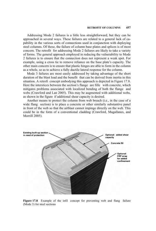
RETROFIT OF COLUMNS 457
Addressing Mode 2 failures is a little less straightforward, but they can beapproached in several ways. These failures are related to a general lack of ca-pability in the various sorts of connections used in conjunction with deployingsteel columns. Of these, the failure of column base plates and splices is of mostconcern. The retrofit for addressing Mode 2 failures are likely to take a varietyof forms. The general approach employed in reducing the vulnerability to Mode2 failures is to ensure that the connection does not represent a weak spot. Forexample, using a cross tie to remove reliance on the base plate’s capacity. Theother main concern is to ensure that plastic hinges are able to form in the columnas a whole, so as to achieve a fully ductile lateral response for the column.
Mode 3 failures are most easily addressed by taking advantage of the shortduration of the blast load and the benefit that can be derived from inertia in thissituation. A retrofi concept embodying this approach is depicted in Figure 17.8.Here the interstices between the section’s flange are fille with concrete, whichmitigates problems associated with localized bending of both the flange andwebs (Crawford and Lan 2005). This may be augmented with additional webs,as shown in the figure if additional shear capacity is desired.
Another means to protect the column from web breach (i.e., in the case of awide flang section) is to place a concrete or other similarly substantive panelin front of the web so that the airblast cannot impinge directly on the web. Thiscould be in the form of a conventional cladding (Crawford, Magallanes, andMorrill 2005).
Figure 17.8 Example of the infil concept for preventing web and flang failure(Mode 3) for steel sections
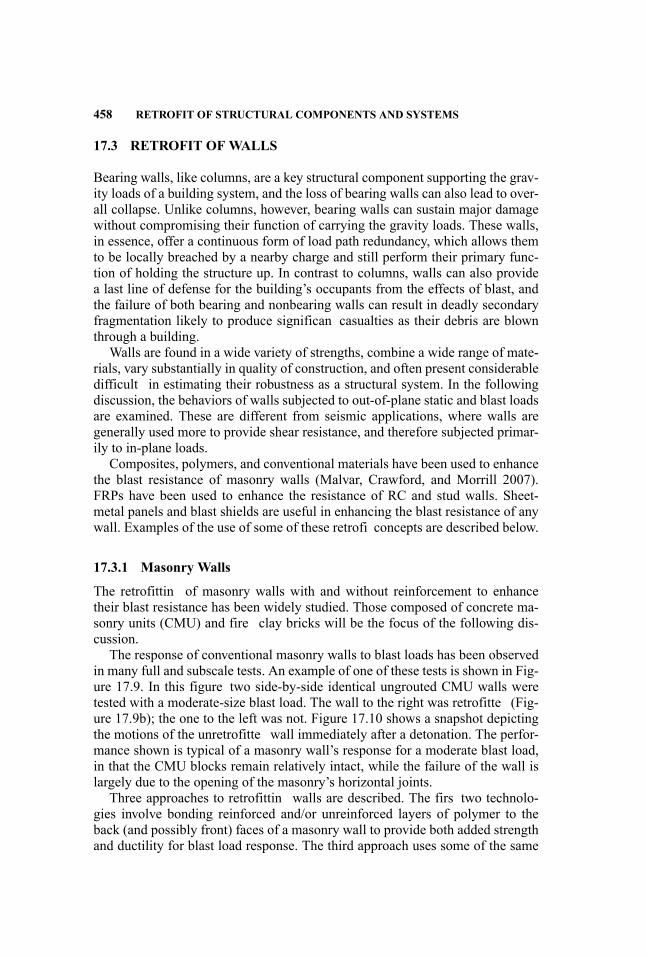
458 RETROFIT OF STRUCTURAL COMPONENTS AND SYSTEMS
17.3 RETROFIT OF WALLS
Bearing walls, like columns, are a key structural component supporting the grav-ity loads of a building system, and the loss of bearing walls can also lead to over-all collapse. Unlike columns, however, bearing walls can sustain major damagewithout compromising their function of carrying the gravity loads. These walls,in essence, offer a continuous form of load path redundancy, which allows themto be locally breached by a nearby charge and still perform their primary func-tion of holding the structure up. In contrast to columns, walls can also providea last line of defense for the building’s occupants from the effects of blast, andthe failure of both bearing and nonbearing walls can result in deadly secondaryfragmentation likely to produce significan casualties as their debris are blownthrough a building.
Walls are found in a wide variety of strengths, combine a wide range of mate-rials, vary substantially in quality of construction, and often present considerabledifficult in estimating their robustness as a structural system. In the followingdiscussion, the behaviors of walls subjected to out-of-plane static and blast loadsare examined. These are different from seismic applications, where walls aregenerally used more to provide shear resistance, and therefore subjected primar-ily to in-plane loads.
Composites, polymers, and conventional materials have been used to enhancethe blast resistance of masonry walls (Malvar, Crawford, and Morrill 2007).FRPs have been used to enhance the resistance of RC and stud walls. Sheet-metal panels and blast shields are useful in enhancing the blast resistance of anywall. Examples of the use of some of these retrofi concepts are described below.
17.3.1 Masonry Walls
The retrofittin of masonry walls with and without reinforcement to enhancetheir blast resistance has been widely studied. Those composed of concrete ma-sonry units (CMU) and fire clay bricks will be the focus of the following dis-cussion.
The response of conventional masonry walls to blast loads has been observedin many full and subscale tests. An example of one of these tests is shown in Fig-ure 17.9. In this figure two side-by-side identical ungrouted CMU walls weretested with a moderate-size blast load. The wall to the right was retrofitte (Fig-ure 17.9b); the one to the left was not. Figure 17.10 shows a snapshot depictingthe motions of the unretrofitte wall immediately after a detonation. The perfor-mance shown is typical of a masonry wall’s response for a moderate blast load,in that the CMU blocks remain relatively intact, while the failure of the wall islargely due to the opening of the masonry’s horizontal joints.
Three approaches to retrofittin walls are described. The firs two technolo-gies involve bonding reinforced and/or unreinforced layers of polymer to theback (and possibly front) faces of a masonry wall to provide both added strengthand ductility for blast load response. The third approach uses some of the same
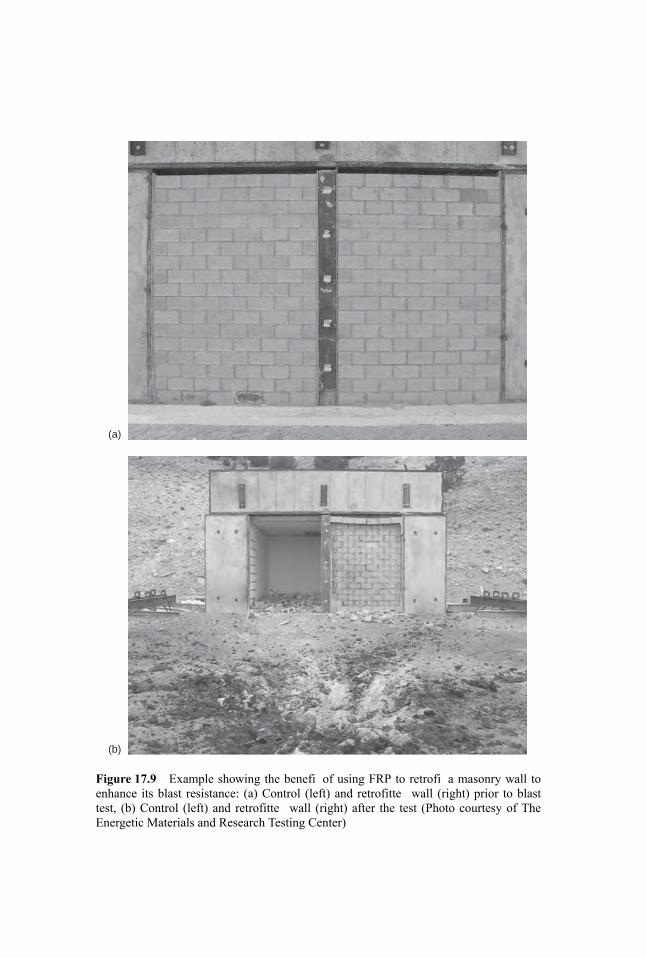
(a)
(b)
Figure 17.9 Example showing the benefi of using FRP to retrofi a masonry wall toenhance its blast resistance: (a) Control (left) and retrofitte wall (right) prior to blasttest, (b) Control (left) and retrofitte wall (right) after the test (Photo courtesy of TheEnergetic Materials and Research Testing Center)
460 RETROFIT OF STRUCTURAL COMPONENTS AND SYSTEMS
Figure 17.10 Example typical of the response expected from a CMU wall struck by ablast; at the time shown, the CMU is moving at several tens of feet per second (Photocourtesy of The Energetic Materials and Research Testing Center)
materials as the firs two, but in this case they are not bonded to the wall. In thissituation, the strengthening elements, such as FRP, are anchored to the floo andact by preventing entry of wall debris rather than by wall strengthening.
Fiber-Reinforced Polymer The use of FRP to enhance the strength and blastresistance of masonry walls has been extensively studied. This would includeFRPs such as CFRP, AFRP, and GFRP.
CMU Studies.Muszynski (1998) and Muszynski and Purcell (2003) bondedCFRP and AFRP to masonry walls composed of concrete masonry units. Bay-lot, Dennis, and Woodson (2000), Baylot et al. (2005), and Dennis, Baylot, andWoodson (2002) conducted experiments on walls using quarter-scale modelsbuilt with typical 8-inch-wide CMU. In these tests, three types of retrofittinschemes were evaluated for ungrouted and for partially grouted walls. The firsretrofi method consisted of 0.04-inch (1 mm) thick GFRP fabric bonded tothe back face of the wall. The second retrofi technique consisted of a two-part sprayed-on polyurea product applied to the back face of the wall. The third
RETROFIT OF WALLS 461
retrofi method used 20-gauge galvanized steel sheet metal attached to the backof the wall. All the walls failed during the blast testing by separating from theframe, but the GFRP and the polyurea retrofitte walls were successful in pre-venting loose fragments within the structure, and were, therefore, considered assuccessful retrofits
Myers, Belarbi, and El-Domiaty (2003, 2004) tested eight ungrouted, un-reinforced masonry (URM) walls retrofitte with FRP (epoxy) laminates andnear-surface-mounted (NSM) rods. Two series of walls (l00 and 200 mm or 4and 8 inches thick) with different slenderness ratios and different strengtheningschemes were tested at varying blast charge weights and standoff distances. Thewalls were only supported at the top and bottom, and retrofitte walls failed inshear at those locations. The FRP laminates were able to contain the wall debris.
Carney and Myers (2003, 2005) tested twelve ungrouted URM walls using apressure bag to apply a uniform loading (Phase I), then field-teste two walls un-der blast (Phase II). Results of the last four Phase I tests, together with the PhaseII tests, are shown in the second paper (Carney and Myers 2005). The wallswere reinforced with GFRP sheets or NSM rods, with and without anchorage.The anchorages consisted of wrapping the sheets around NSM rods embeddedinto the wall’s top and bottom support for the firs case, and of extending theNSM rod three inches into the wall support for the second. Strengthening the an-chorages almost doubled the capacity of the walls. In contrast, unanchored NSMrods did not show any improvement. For FRP reinforced walls, no shear failurewas observed during the static tests, while it was apparent in previous blast tests(Myers, Belarbi, and El-Domiaty 2003), indicating a potential limitation in theuse of static tests to simulate blast tests.
Stanley, Metzger, and Martinez et al. (2005) used a retrofi system composedof multiple layers of carbon and glass FRP in an epoxy resin (applied with paintrollers), placed on the interior and exterior surfaces of the CMU wall test spec-imen. This system was successful in containing debris but seemed too labor in-tensive to apply. Stanley, Metzger, and Morrill et al. (2005a) used two layers of aglass FRP in an epoxy resin applied to the interior surface of the CMU wall testspecimen. This wall experienced complete failure, indicating that stiff retrofisystems fail catastrophically once their capacity is exceeded.
Simmons (2005) studied the effectiveness of three types of retrofit (E-glass,22-gauge steel, and an elastomeric polymer) on CMU walls to increase theirresistance to primary fragments from a 120-mm mortar round and a 122-mmrocket; he found that the E-glass significantl reduced the number of fragmentsthat passed through the wall.
Brick Studies. Conley and Mlakar (1999) used CFRP (epoxy) strips to rein-force small brick walls loaded with a gas-loaded piston and subjected to one-waybending. Increases in load capacity of 400% were recorded.
Patoary and Tan (2003) completed static tests using air bags on four built-insolid masonry brick walls retrofitte with three types of FRP systems: glass, car-bon, and low-strength fibe glass woven roving. The walls, 120-mm thick, wereable to sustain deflection up to 20 mm. Specimens with GFRP or CFRP failed
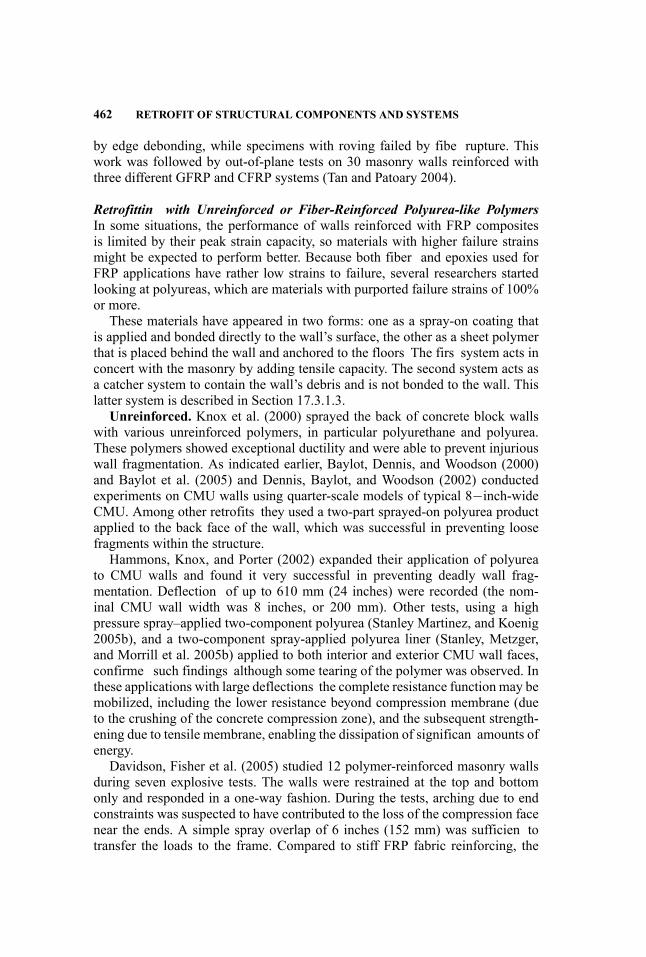
462 RETROFIT OF STRUCTURAL COMPONENTS AND SYSTEMS
by edge debonding, while specimens with roving failed by fibe rupture. Thiswork was followed by out-of-plane tests on 30 masonry walls reinforced withthree different GFRP and CFRP systems (Tan and Patoary 2004).
Retrofittin with Unreinforced or Fiber-Reinforced Polyurea-like PolymersIn some situations, the performance of walls reinforced with FRP compositesis limited by their peak strain capacity, so materials with higher failure strainsmight be expected to perform better. Because both fiber and epoxies used forFRP applications have rather low strains to failure, several researchers startedlooking at polyureas, which are materials with purported failure strains of 100%or more.
These materials have appeared in two forms: one as a spray-on coating thatis applied and bonded directly to the wall’s surface, the other as a sheet polymerthat is placed behind the wall and anchored to the floors The firs system acts inconcert with the masonry by adding tensile capacity. The second system acts asa catcher system to contain the wall’s debris and is not bonded to the wall. Thislatter system is described in Section 17.3.1.3.
Unreinforced. Knox et al. (2000) sprayed the back of concrete block wallswith various unreinforced polymers, in particular polyurethane and polyurea.These polymers showed exceptional ductility and were able to prevent injuriouswall fragmentation. As indicated earlier, Baylot, Dennis, and Woodson (2000)and Baylot et al. (2005) and Dennis, Baylot, and Woodson (2002) conductedexperiments on CMU walls using quarter-scale models of typical 8−inch-wideCMU. Among other retrofits they used a two-part sprayed-on polyurea productapplied to the back face of the wall, which was successful in preventing loosefragments within the structure.
Hammons, Knox, and Porter (2002) expanded their application of polyureato CMU walls and found it very successful in preventing deadly wall frag-mentation. Deflection of up to 610 mm (24 inches) were recorded (the nom-inal CMU wall width was 8 inches, or 200 mm). Other tests, using a highpressure spray–applied two-component polyurea (Stanley Martinez, and Koenig2005b), and a two-component spray-applied polyurea liner (Stanley, Metzger,and Morrill et al. 2005b) applied to both interior and exterior CMU wall faces,confirme such findings although some tearing of the polymer was observed. Inthese applications with large deflections the complete resistance function may bemobilized, including the lower resistance beyond compression membrane (dueto the crushing of the concrete compression zone), and the subsequent strength-ening due to tensile membrane, enabling the dissipation of significan amounts ofenergy.
Davidson, Fisher et al. (2005) studied 12 polymer-reinforced masonry wallsduring seven explosive tests. The walls were restrained at the top and bottomonly and responded in a one-way fashion. During the tests, arching due to endconstraints was suspected to have contributed to the loss of the compression facenear the ends. A simple spray overlap of 6 inches (152 mm) was sufficien totransfer the loads to the frame. Compared to stiff FRP fabric reinforcing, the
RETROFIT OF WALLS 463
spray materials were cheaper, bonded better to the wall, and were easier to anchorto the frame (see also Davidson, Porter et al. 2004).
Reinforced. These polyurea polymers can also be further strengthened withcontinuous fibers which can provide some additional energy dissipation up tofibe rupture. Tests were conducted by Crawford and Morrill (2002) to definthe properties of reinforced and nonreinforced polyurea spray-on coatings.These materials were used to retrofi masonry walls subjected to blast loads.This is detailed in several studies (Crawford and Morrill 2003a, 2003b; Johnson,Slawson, Cummins et al. 2003, 2004; Johnson and Slawson 2004; Morrill,Nicolaisen, and Hutchinson 2005; Piepenburg et al. 2002, 2003; Stanley,Metzger, and Morrill et al. 2005c; Stanley, Metzger, and Koenig. 2005a).
Piepenburg et al. (2002) used an aramid grid fabric to reinforce a polyureaspray retrofi of a CMU wall, and were successful in containing the CMU de-bris. Piepenburg et al. (2003) also used an aramid within two thin sprayed-onpolyurea layers on a CMU wall. Crawford and Morrill (2003a) describe a retroficonsisting of an aramid laminate that is secured to the wall with a polyurethaneadhesive, and anchored to the diaphragms with energy-dissipating compliant an-chorages. Johnson, Slawson, and Cummins et al. (2003, 2004) used an open-weave aramid with different fibe lay-ups with a spray-on polyurea. The capacityof the walls retrofitte with reinforced polyurea was 1.4–2.0 times higher thanthat of the walls retrofitte with just polyurea, and 5.5–7.5 higher than that of theunretrofitte walls. Morrill, Nicolaisen, and Hutchinson (2005) used a polyureacoating, with and without an aramid fibe mesh, on the back side of brick wallsamples tested quasi-statically in a laboratory environment. These tests were use-ful in determining complete quasi-static resistance functions, including tensilemembrane.
Stanley, Metzger, and Morrill et al. (2005c) used a spray-applied two-partpolyurea with an inner aramid weaved fabric on a CMU wall, and successfullystopped the CMU debris. Peak deflection were about 230 mm (9 inches). Stan-ley, Martinez, and Koenig (2005a) used a non-woven polypropylene geotextilefabric in between two layers of sprayed-on polyurethane applied to the interiorand exterior surfaces of the CMU wall test specimen. In this case, the retrofittewall did fail, although it would appear that the retrofi had provided some amountof early-time confinemen and lateral restraint of the CMU blocks.
Retrofittin with Catcher Systems In contrast to the retrofi schemes describedfor walls above, which are related to strengthening them directly, catchersystems are placed behind the wall to catch any debris that might be generatedby its breakup from a blast. Such a device may be composed of thin sheetsof fabric (e.g., Kevlar R© laminate), sheet metal, or polymer (e.g., as shown inFigure 17.11).
This form of catcher system may be augmented with cables for cases in-volving particularly high loads (e.g., impulses of thousands of psi-ms) or whereanchorage conditions prohibit the use of the sheets by themselves. These systemsare designated as cable catcher systems.
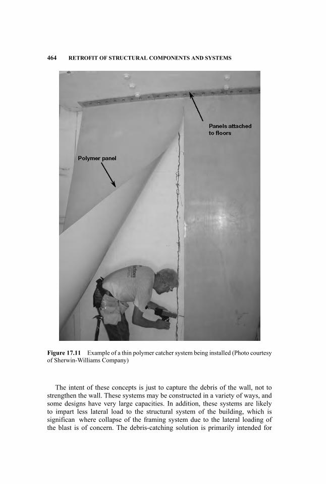
464 RETROFIT OF STRUCTURAL COMPONENTS AND SYSTEMS
Figure 17.11 Example of a thin polymer catcher system being installed (Photo courtesyof Sherwin-Williams Company)
The intent of these concepts is just to capture the debris of the wall, not tostrengthen the wall. These systems may be constructed in a variety of ways, andsome designs have very large capacities. In addition, these systems are likelyto impart less lateral load to the structural system of the building, which issignifican where collapse of the framing system due to the lateral loading ofthe blast is of concern. The debris-catching solution is primarily intended for

RETROFIT OF WALLS 465
Figure 17.12 Example of the type of composite panels that may be used for retrofittinmasonry and stud walls to enhance their blast resistance
non-load-bearing walls whose function is not critical to preventing failure of thestructural system. However, these systems may also be applied to bearing walls,where the breadth of the wall failure incurred can be spanned by the remainingstructural system.
In 2004, a series of reinforced and unreinforced polymer panels for retrofittinmasonry walls was developed (Crawford, Lan, and Wu 2009). These panels aredelivered to the site in the form of sheets, which are placed behind the wall andanchored to the floor to hold them in place, as shown in Figure 17.11. Thesepanels have shown their worth against both vehicle and rocket blast threats intests in Israel and the U.S.
Retrofittin with Composite Panels In 2000, large-capacity catcher systemswere introduced and validated in blast tests (Crawford 2001) for retrofittin ma-sonry or stud walls. These systems employed composite panels, like the oneshown in Figure 17.12, that were composed of FRP or steel sheets bonded to acrushable core material, such as the rigid polyurethane foam shown in the figureThe panel is placed behind the wall and anchored to the floo , generally using acompliant anchorage. These systems have been proved successful in blast testsfor both masonry and metal stud walls, and were shown to work for very highloads if the anchorage is designed appropriately (Crawford 2001, Crawford, Xin,and Bogosian 2002).
Retrofittin withConventionalMethods Conventional methods (e.g., shotcreteand dowels) may also be used to retrofi a masonry wall to enhance its blast

466 RETROFIT OF STRUCTURAL COMPONENTS AND SYSTEMS
resistance, or just to prevent its debris from propagating into the building. Thesesystems should provide continuous support to the existing masonry wall to pre-vent localized breaching. Such systems would be expected to be less efficienthan those already mentioned. Moreover, the generally large quantities of ma-terials used to install these types of retrofit may add to the risks from blast byintroducing considerably more material that could become a source of debris.
17.3.2 Stud Walls
Knox et al. (2000), and Crawford and Morrill (2003a, 2003b) also studied theretrofi of wood and steel stud walls, using composite materials, which providedan excellent means for adding blast protection to an existing stud frame building.In the Crawford andMorrill studies, both fabric and sheet metal composites, suchas the one shown in Figure 17.12, were deployed.
17.4 FLOORS
Considerations of the blast protection afforded by the floor of a building arelikely to involve three kinds of situations, which are related to the location of thedetonation:
� Case 1: Considerations for detonations outside the building, where the det-onation is some distance away. Here, enhancing the resistance of the floomay be unnecessary or may be accomplished using conventional strength-ening techniques, mainly because the floor s response is neither very pro-nounced nor complex. The actual distance in question depends on the typeof exterior wall, the floor s properties, and other factors.
� Case 2: Considerations for exterior detonations near the building, with nowall present (e.g., near a loading dock). Here, an upward shock could beimparted to a floo above the detonation and downward motion imparted tothe floo below the detonation.
� Case 3: Interior detonation. Here, considerations for two situations are ofissue: the blast above, and the blast below a floo . For an interior detonation,gas pressures may be of major concern. In this case, adding venting mightbe part of the retrofi strategy.
Retrofittin floor to provide protection from blast is likely to be more prob-lematic than retrofittin any other structural component, mainly because of thelarge spans and loaded areas, their load resistance being primarily related to grav-ity (i.e., with limited resistance to uplift), and the possibility that the detonationmay be quite close (e.g., a bomb resting on the floor) Moreover, in contrast tomost other retrofi strategies, the weight of the floo retrofi can be an issue be-cause of the floor s extent.

FLOORS 467
The following are three retrofi strategies for addressing the three threat situ-ations mentioned above.
� Case 1. When the bomb is outside, the walls are likely to knock the blastdown sufficientl so that the floo response may be ignored—especiallysince it’s likely in such a case that the walls would be retrofitte first andeven less load would reach the floo . Moreover, the main concern is the netload acting on the floo , which may be negligible, even if the walls fail.However, in situations where the facades above and below a floo have verydifferent blast resistance (e.g., ground floor that have no exterior walls), asubstantial net upward (or downward) load on a floo can be generated, andthe situation may require some form of mitigation.
� Case 2. If the bomb is relatively close to the outside of a building and oppo-site an opening in the wall (or possibly a glass facade), the floo , especiallyabove the bomb, which would be loaded in its weak direction, may be acause of concern. Here, however, the effects of gas pressure can probablybe ignored.
� Case 3. For an interior detonation, both shock and gas pressure componentsof the blast may cause concern.
The risks associated with a floo hit by a blast depend greatly on the size andlocation of the bomb. For example, is the detonation from a bomb on the floo ,or above/below the floor This has mostly to do with proximity and whether theresponse is mainly localized or involves the whole of the floo , the magnitude ofvelocity (shock) imparted to the floo and possible debris generated from it, andwhether the floo is loaded on its strong or weak axis.
Protection for floor against nearby bombs (i.e., within a few feet) is likely tobe impractical. For example, for a bomb resting on a conventional floo , there arefew (or no) reasonably priced ways to prevent the floor s breach. Where the blastis above the floo , then attaching a catcher system to the joists to prevent debrispropagation could be a good strategy.
For situations involving a vented blast occurring beneath a floo that hasa reasonable standoff, retrofittin the floo with an FRP may suffice How-ever, even if the floo remains relatively undamaged, there is likely to be sig-nifican shock imparted to it, which can cause severe injuries to those stand-ing on it and launch furnishings, providing another source for injuries. Betterprotection can be provided by a blast shield, possibly hung below the actualfloo , to either mitigate or prevent the airblast from striking the floo . In thiscircumstance, not only is the floo not damaged, but the velocity impartedby the shock, resulting in the launch of furnishings and people, is avoidedaltogether.
The selection of a retrofi strategy for floor is likely to primarily involvelimiting the risks, rather than eliminating them. Three basic retrofi strategies,depending on the bomb’s size and location, seem most applicable to addressing

468 RETROFIT OF STRUCTURAL COMPONENTS AND SYSTEMS
the vulnerability presented by floors
� Strengthening the existing floo through the addition of ductility andcapacity.
� Debris containment. This strategy is particularly useful for those floor indirect contact with or very near to the bomb.
� Shielding. Shielding a floo from the blast load avoids the issue altogether.This could also include constructing a second floo directly above/below theexisting one that is directly exposed to the threat. Alternatively, the existingfloo may be retrofitte so that it can provide the protection for a new floo .
Retrofi strategies for floor are likely to be much more difficul to implementthan for walls, which would imply that the best strategy here is to prevent a bombor an airblast from getting close enough to present a serious risk to the floorsand to use the walls of the building to protect the floors Even for a loading dock,using roll-up doors or some other form of closure can probably deflec the blastenough so that a floo above it is sufficientl protected.
17.5 BEAMS/GIRDERS/CONNECTIONS
The retrofi strategies pertaining to enhancing the blast protection afforded bystructural components that act as beams, girders, and the connections associatedwith them—hereafter collectively referred to as beams—are generally of lessconcern than the components already mentioned, because in many ways thesecomponents generally present less of a risk.
Retrofi strategies for beams to accommodate blast loads are likely to be rel-atively simple and probably similar to those that might be used in conventionalretrofi strategies, especially for blast loads that are generated by charges thatpredominantly excite the fundamental modes of the beam.
In addition, whether the blast is pushing up or down on the beam can makea substantial difference in its response. Many beams are not as well attached inthe upward direction, and may have similar weaknesses in terms of their abilityto resist lateral loads. For closer charges, retrofi strategies are likely to be site-specifi and not easily addressed with simplifie tools and conventional retrofistrategies.
Blast effects data for beams (Crawford, Magallanes, and Morrill 2005,Magallanes and Morrill 2008), although sparse, indicate that the beams them-selves are likely to be less of an issue than their support connections. For externalblast, it is likely that the net loads pushing up/down on the beam will be negligi-ble. However, loading on a beam can be quite localized (e.g., a bomb placed onthe floo immediately above the beam), or broad-based; for example, if applied toa robust floo system that is strongly coupled to the beams framing it, the beam’sloading would derive from a large tributary area.
SUMMARY 469
A major concern for beams is their attachment (i.e., connections) to their sup-port (e.g., columns). For many steel beams, especially in nonseismic designs,this may consist of only a shear tab, or for precast beams only a small ledger towhich it is only lightly attached (e.g., the shear tab shown in Figure 17.7b).
Several retrofi concepts have been developed for seismic applications to im-prove the anchorage of beams/girders at their supports that would also work inblast environments, although they may need to be more robust. Another retrofistrategy that has been used (Crawford and Lan 2005) relies on cabling attached tothe beams to carry the load, should their connection to the columns be damaged.
17.6 STRUCTURAL SYSTEM
The preceding sections addressed ways to retrofi structural components to en-hance their survivability and protective capability in the event of a blast. It isalso important, perhaps even more so, to evaluate the structural system’s perfor-mance, especially once the retrofit are in place.
However, evaluating the risks to the system and describing retrofi strategiesfor addressing them is beyond the scope of this chapter. With regard to assess-ing risks to the system, however, it is important to recognize that retrofittinstructural components can produce deleterious effects in terms of the system’sperformance. For instance, there would be a need to ensure that the impact ofthe additional loading imparted to the system by any enhancement in the pro-tection be evaluated—for example, the added lateral load imparted to the systemby the addition of blast-resistant walls could exacerbate the lateral response of abuilding system sufficientl to cause its failure from excessive story drift.
17.7 SUMMARY
Information was presented in this chapter pertaining to retrofittin a facility’sstructural framing system and components to enhance the protection affordedby them in the event that a blast occurs. Each of the major components of thestructural system was addressed, including columns, walls, beams, and floorsSeveral strategies were described for mitigating risks from blast for each type ofcomponent.
17.7.1 Inexact Science
The ideas presented in this chapter concerning the retrofi of structural compo-nents to enhance the blast protection afforded by them can only, due to spacelimitations, reflec a general notion of strategies and methods that may be pur-sued in this endeavor. Moreover, only a few of the ways this might be accom-plished could be cited, and all the concerns and complexities that might arise inan actual application could not be addressed. What is intended, however, is toapprise those desirous of developing retrofi strategies and designs of some of
470 RETROFIT OF STRUCTURAL COMPONENTS AND SYSTEMS
the main issues and methods that have been found useful and effective, and todescribe extant test data and studies that are available.
Developing retrofi designs for any structure is often more art than engineer-ing because each situation is likely to be unique, to have issues of unintendedconsequences, to raise difficultie of identifying the extant design, and so forth.In addition, blending with the existing structure, architecture, and functionalityis likely to present a host of conflictin constraints, making the retrofi even moredifficult
It is likely that any retrofi design will not be able to offer the same certaintyof function as a new design. Moreover, achieving too high a certainty is likelyto result in a poorer level of protection or perhaps none at all—that is, there isa certain paralyzing effect that can easily be reached by demanding too muchcertainty. On the other hand, there is a particular need in this type of engineeringto be certain that the design is not fatally fl wed. Adopting a good enough stan-dard may offer the best course for this type of work, the main issue here beingthe difficult of definin such a standard ahead of time (e.g., for the purposes ofgenerating a contract and design budget).
17.7.2 Complexities
Retrofittin a structure to enhance its resistance to blast may require an inordinatelevel of skill and experience. The limited amount of information presented in thischapter can only allude to some of the considerations that are needed to developthese retrofit and their integration with the existing structure, and should beviewed as just an introduction to the subject.
It is important to recognize that, in many cases, the intensity and rapidity ofthe blast load generate behaviors substantially different than generally encoun-tered in structural design problems. Moreover, the forces and material damageincurred are often difficul to determine without using HFPB finit element mod-els, and for most retrofi designs, they are likely to be much higher than ordinarilydealt with, requiring a familiarity with material and dynamic response behaviorsin this high loading rate regime.
The level of complexity and difficult encountered in developing retrofi de-signs is likely to be highly exacerbated when the blast load is from a large,close charge. These situations can be addressed, but they require considerationsin addition to those that can be alluded to here. Moreover, in these situations,many simplifie engineering models commonly used for blast effects analysisare likely to be deficien and misleading in their prediction of response.
REFERENCES
American Concrete Institute, Committee 440. 2002. Design and Construction of Exter-nally Bonded FRP Systems for Strengthening Concrete Structures (ACI 440.2R-02).Farmington Hills, MI: American Concrete Institute.
SUMMARY 471
Baylot J. T., B. Bullock, T. R. Slawson, and S. C. Woodson. 2005. Blast responseof lightly attached concrete masonry unit walls. Journal of Structural Engineering131 (8): 1186–1193.
Baylot J. T., S. T. Dennis, and S. C. Woodson. 2000. Response of 1/4 scale concrete ma-sonry unit (CMU) walls to blast. In Emerging Technologies in Fluids, Structures, andFluid/Structure Interactions, Vol. 1. Proceedings of the 2000 ASME Pressure Vesselsand Piping Conference, Seattle, WA, July 23–27, 2000. New York: American Societyof Mechanical Engineers.
Carney, P. and J. J. Myers. 2003. Shear and fl xural strengthening of masonry infil wallswith FRP for extreme out-of-plane loading. Proceedings, Architectural EngineeringInstitute Annual Meeting, Austin, TX, 2003.
. 2005. Out-of-plane static and blast resistance of unreinforced masonrywall connections strengthened with FRP. In 7th International Symposium on Fiber-Reinforced Polymer Reinforcement for Concrete Structures, ACI Symposium Publica-tion 230, 229–248. Farmington Hills, MI: American Concrete Institute.
Conley C. H. and P. F. Mlakar. 1999. Blast resistance of CFRP reinforced masonry. Pre-sented at the 70th Shock and Vibration Symposium, Albuquerque, NM, November15–19, 1999.
Crawford J. E. 2001. Addressing workplace protection issues more effectively. Proceed-ings of the Society of American Military Engineers Symposium on ComprehensiveForce Protection, Charlestown, SC, November 1–2, 2001.
Crawford J. E., D. D. Bogosian, and J. W. Wesevich. 1997. Evaluation of the effects ofexplosive loads on masonry walls and an assessment of retrofi techniques for increas-ing their strength. Presented at the 8th International Symposium on the Interaction ofthe Effects of Munitions with Structures, Defense Special Weapons Agency, McLean,VA, April 1997.
Crawford J. E. and S. Lan. 2005. Design and implementation of protection technolo-gies for improving blast resistance of buildings. Presented at the Enhancing BuildingSecurity Seminar, Singapore, March 2005.
Crawford J. E., S. Lan, and Y. Wu. 2009. Design methods for enhancing the blast re-sistance of masonry walls and windows with bonded and unbonded polymer sheets.Proceedings of the 8th International Conference on Shock and Impact Loads on Struc-tures, Adelaide, Australia, December 2–4, 2009.
Crawford J. E., J. J. Magallanes, and K. B. Morrill. 2005. Vulnerability of steel framingsystems. Proceedings of the 12th International Symposium on the Effects of Munitionswith Structures, New Orleans, LA, September 26–30, 2005.
Crawford J. E., L. J. Malvar, B. W. Dunn, and D. J. Gee. 1996. Retrofi of reinforcedconcrete columns using composite wraps to resist blast effects. Proceedings of the27th Department of Defense Explosive Safety Seminar, Las Vegas, NV, August 19–22,1966.
Crawford J. E., L. J. Malvar, J. M. Ferritto, K. B. Morrill, B. W. Dunn, and P. Bong.2003. Description of Design Software for Retrofittin Reinforced Concrete Columnsto Improve Their Resistance to Blast. (Report TR-01-16.2). Burbank, CA: Karagozianand Case. Limited Distribution.
Crawford J. E., L. J. Malvar, K. B. Morrill, and J. M. Ferritto. 2001. Composite retrofit toincrease the blast resistance of reinforced concrete buildings. Proceedings of the 10th
472 RETROFIT OF STRUCTURAL COMPONENTS AND SYSTEMS
International Symposium on Interaction of the Effects of Munitions with Structures,San Diego, CA, May 2001.
Crawford, J. E. and K. B. Morrill. 2002. New highly ductile designs for preventing injuri-ous wall debris due to a terrorist bombing. Proceedings of the Protection of StructuresAgainst Hazards, Singapore, November 2002.
. 2003a. Retrofi techniques using polymers and fibe reinforced polymers forpreventing injurious wall debris. Proceedings of the 6th International Symposium onFibre-Reinforced Polymer Reinforcement for Concrete Structures, FRPRCS-6, Singa-pore, July 8–10, 2003, pp. 1199–1208.
. 2003b. Retrofi techniques for strengthening stud walls subjected to nearbyblast loads. Proceedings, 74th Shock and Vibration Symposium, San Diego, CA, Oc-tober 27–31, 2003. Limited Distribution.
Crawford J. E., J. Wesevich, J. Valancius, and A. Reynolds. 1995. Evaluation of jack-eted columns as a means to improve the resistance of conventional structures to blasteffects. Proceedings, 66th Shock and Vibration Symposium, Biloxi, MS, October30–November 2, 1995.
Crawford J. E., X. Xin, and D. D. Bogosian. 2002. Retrofi techniques for conventionalwalls to prevent their causing injurious debris due to a terrorist bombing. Proceedingsof the 17th International Symposium on Military Aspects of Blast and Shock, LasVegas, NV, June 10–14, 2002.
Davidson J. S., J. W. Fisher, M. I. Hammons, J. R. Porter, and R. J. Dinan. 2005. Failuremechanisms of polymer reinforced concrete masonry walls subjected to blast. Journalof Structural Engineering 131 (8): 1194–1205.
Davidson J. S., J. R. Porter, R. J. Dinan, M. I. Hammons, and J. D. Connell. 2004. Explo-sive testing of polymer retrofi masonry walls. Journal of Performance of ConstructedFacilities 18 (2): 100–106.
Defense Special Weapons Agency (DSWA). 1998. Design and Analysis of HardenedStructures to Conventional Weapons Effects (TM 5-855-1, AFPAM 32-1147(1), NAV-FAC P-1080, DAHSCWEMAN-97). Washington, DC: The Departments of the Army,Air Force, Navy, and The Defense Special Weapons Agency.
Dennis S. T., J. T. Baylot, and S. C. Woodson. 2002. Response of 1/4 scale con-crete masonry unit (CMU) walls to blast. Journal of Engineering Mechanics 128 (2):134–142.
Federal Emergency Management Agency, Building Performance Analysis Team. 1996.The Oklahoma City Bombing: Improving Building Performance through Multi-Hazard Mitigation (FEMA 277). Washington, DC: Federal Emergency ManagementAgency.
Hammons M. I., K. J Knox, and J. R. Porter. 2002. Polymer materials for blast retrofiof masonry construction. Proceedings, 30th Department of Defense Explosives SafetySeminar, Atlanta, GA, August 13–15, 2002.
Johnson C. F. and T. R. Slawson. 2004. Concrete masonry units walls retrofittewith fibe reinforced elastomeric systems for blast loads. Presented at the 75thShock and Vibration Symposium, Virginia Beach, VA, October 27–31, 2004. LimitedDistribution.
Johnson C. F., T. R. Slawson, T. K. Cummins, M. B. Hueste, and L. Beason. 2003.Concrete masonry units (CMU) static and dynamic wall experiments with elastomeric
SUMMARY 473
retrofits Presented at the 74th Shock and Vibration Symposium, San Diego, CA, Oc-tober 27–31, 2003. Limited Distribution.
Johnson C. F., T. R. Slawson, T. K. Cummins, and J. L. Davis. 2004. Concrete masonryunit walls retrofitte with elastomeric systems for blast loads. Presented at the 24thArmy Science Conference, Orlando, FL, November 29–December 2, 2004.
Kersul A. M. and D. Sunshine. 2002. Structural collapse blast mitigation. Presented atthe 17th International Symposium on Military Aspects of Blast and Shock, Las Vegas,NV, June 10–14, 2002.
Knox K. J., M. I. Hammonds, J. R. Porter, and T. T. Lewis. 2000. Polymer materials forstructural retrofit Proceedings, 29th Department of Defense Explosives Safety Semi-nar, New Orleans, LA, July 18–20, 2000.
Magallanes J. M. and K. B. Morrill. 2008. Fast running model for the residual capacityof steel columns damaged by blast & fragment loads. Proceedings of the 79th Shockand Vibration Symposium, Orlando, FL, October 26–30, 2008.
Malvar L. J. 1998a. Durability of composites in concrete. Presented at First Interna-tional Conference on Durability of Composites for Construction, Sherbrooke, Quebec,Canada, August 5–7, 1988, pp. 361–372.
. 1998b. Review of static and dynamic properties of steel reinforcing bars. ACIMaterials Journal 95 (5): 609–616.
Malvar L. J., J. E. Crawford, and K. B. Morrill. 2007. Use of composites to resist blast.Journal of Composites for Construction 11 (6): 601–610.
Malvar L. J., K. B. Morrill, and J. E. Crawford. 1999. CTS-1 Retrofi Designs: For Reduc-ing the Vulnerability of an Offic Building to Airblast (Report TR-98-39.2). Burbank,CA: Karagozian & Case.
. 2004. Numerical modeling of concrete confine by fibe reinforced compos-ites. Journal of Composites for Construction 8 (4): 315–322.
Malvar L. J. and C. A. Ross. 1998. Review of static and dynamic properties of concretein tension. ACI Materials Journal 95 (6): 735–739.
Malvar L. J. and J. W.Wesevich. 1996. Peak Compression Membrane Response Enhance-ments for One-Way and Two-Way Slab Resistance Functions (TM-96-1.2). Burbank,CA: Karagozian & Case.
Morrill, K. B., J. E. Crawford, and J. M. Magallanes. 2007. “Development of Simpli-fie Tools to Predict the Blast Response of Steel Beam-Column Connections,” Pro-ceedings of the 2007 ASCE/SEI Structures Congress, Long Beach, CA, May 16–19,2007.
Morrill K. B., L. J. Malvar, and J. E. Crawford. 1999. Retrofi design procedure for exist-ing RC buildings to increase their resistance to terrorist bombs. Proceedings of the 9thInternational Symposium on Interaction of the Effects of Munitions with Structures(IEMS), Berlin, Germany. May 3–7, 1999.
Morrill K. B., L. J. Malvar, J. E. Crawford, and S. W. Attaway. 2000. RC column andslab retro-fit to survive blast loads. Proceedings of the ASCE Structures Congress,Philadelphia, PA, May 8–10, 2000.
Morrill K. B., L. J. Malvar, J. E. Crawford, and J. M. Ferritto. 2004. Blast resistant designand retrofi of reinforced concrete columns and walls. Presented at ASCE StructuresCongress, Nashville, TN, May 23–25, 2004.

474 RETROFIT OF STRUCTURAL COMPONENTS AND SYSTEMS
Morrill K. B., L. J. Malvar, J. E. Crawford, G. Hegemier, and F. Seible. 2001. Full-scale testing of reinforced concrete column retrofit to resist blast loads. Proceedingsof the 10th International Symposium on Interaction of the Effects of Munitions withStructures, San Diego, CA, May 2001.
Morrill K. B., K. Nicolaisen, and T. Hutchinson. 2005. Laboratory Testing of Kevlar R©Reinforced Polyurea© (Report TR-04-52.1). Burbank, CA: Karagozian & Case.
Muszynski L. C. 1998. Explosive fiel tests to evaluate composite reinforcement of con-crete and masonry walls. In Fiber Composites in Infrastructure, Proceedings of theSecond International Conference on Composites in Infrastructure, Tucson, Arizona,January 5–7, 1998, pp. 277–284.
Muszynski L. C. and M. R. Purcell. 2003. Use of composite reinforcement to strengthenconcrete and air-entrained concrete masonry walls against air blast. Journal of Com-posites for Construction 7 (2): 98–108.
Myers J. J., A. Belarbi, and K. A. El-Domiaty. 2003. Blast resistance of un-reinforcedmasonry walls retrofitte with fibe reinforced polymers. Proceedings for The NorthAmerican Masonry Society 2003 Annual Meeting, Clemson, South Carolina, pp.312–323.
. 2004. Blast resistance of FRP retrofitte un-reinforced masonry (URM) wallswith and without arching action. The Masonry Society Journal 22 (1): 9–26.
Patoary M. K. H. and K. H. Tan. 2003. Blast resistance of prototype in-built masonrywalls strengthened with FRP systems. Proceedings of the 6th International Symposiumon Fibre-Reinforced Polymer Reinforcement for Concrete Structures, FRPRCS-6, Sin-gapore, July 8–10, pp. 1189–1198.
Perea, A. and K. B. Morrill. 2002. Component high explosive testing of bare andretrofitte columns. Presented at the 17th International Symposium on Military As-pects of Blast and Shock, Las Vegas, NV, June 10–14, 2002.
.Piepenburg, D., R. Martinez, R. Del Frate, and K. Morrill. 2002. Blast Resistance Up-grade for Glazing, Window Frame, and Wall Systems—Non-Load Bearing In-FillWalls with Blast Retrofit applied to the Wall, Window Frame and Glaze (Report No.SAIC-03/1001). San Diego, CA: Science Applications International Corporation.
. 2003. Blast Resistance Upgrade for Glazing, Window Frame, and Wall Sys-tems – Load Bearing Walls with Blast Retrofit applied to the Wall, Window Frame andGlaze (Report No. SAIC-03/1003). San Diego, CA: Science Applications InternationalCorporation.
Simmons, L. 2005. Arena fragment experiments using mortars. Presented at the 76thShock and Vibration Symposium, Destin, FL, October 30–December 4, 2005.
Stanley, M., R. Martinez, and J. Koenig. 2005a. UL-Like Testing of Commercial Off-the-Shelf Products that Enhance the Blast and Ballistic Resistance of Structures, QuickLook Report 6 (New Mexico Tech, Energetic Materials Research and Testing Center,TR-05-08). Burbank, CA: Karagozian & Case. Limited Distribution.
. 2005b. UL-Like Testing of Commercial Off-the-Shelf Products that Enhancethe Blast and Ballistic Resistance of Structures, Quick Look Report 7 (New MexicoTech, Energetic Materials Research and Testing Center, TR-05-14). Burbank, CA:Karagozian & Case. Limited Distribution.
Stanley, M., J. Metzger, R. Martinez, and J. Koenig. 2005. UL-Like Testing of Com-mercial Off-the-Shelf Products that Enhance the Blast and Ballistic Resistance of
SUMMARY 475
Structures, Quick Look Report 5 (NewMexico Tech, Energetic Materials Research andTesting Center, TR-05-03). Burbank, CA: Karagozian & Case. Limited Distribution.
Stanley, M., J. Metzger, K. B. Morrill, and R. Martinez. 2005a. UL-Like Testing ofCommercial Off-the-Shelf Products that Enhance the Blast and Ballistic Resistance ofStructures, Quick Look Report 2 (NewMexico Tech, Energetic Materials Research andTesting Center, TR-04-48). Burbank, CA: Karagozian & Case. Limited Distribution.
. 2005b. UL-Like Testing of Commercial Off-the-Shelf Products that Enhancethe Blast and Ballistic Resistance of Structures, Quick Look Report 3 (New MexicoTech, Energetic Materials Research and Testing Center, TR-04-50). Burbank, CA:Karagozian & Case. Limited Distribution.
. 2005c. UL-Like Testing of Commercial Off-the-Shelf Products that Enhancethe Blast and Ballistic Resistance of Structures, Quick Look Report 4 (New MexicoTech, Energetic Materials Research and Testing Center, TR-04-55). Burbank, CA:Karagozian & Case. Limited Distribution.
Tan K. H. and M. K. H. Patoary. 2004. Strengthening of masonry walls against out-of-plane loads using fibe -reinforced polymer reinforcement. Journal of Compositesfor Construction 8 (1): 79–87.
INDEX
Aacetone peroxide, 26Alfred P. Murrah Federal Building, 17,
22, 27, 173, 446, 447alternative load path, 8Amman, 25analysis methods, 243, 244, 256, 389Baker-Strehlow-Tang (BST), 179blast curves, 179component modeling, 249computational flui dynamics (CFD),178
connections, 252effects of preload, 251envelope design approaches, 265–67equivalent static loads, 112explicit dynamic finit elements,256
finit elements, 120, 245, 269for moment frames, 246for steel-braced frames, 247multi-degree-of-freedom, 254, 256,268
P-I diagrams, 253, 267precast tilt-up construction, 247precision of, 15ray-tracing procedures, 209reinforced masonry, 247resistance factors, 112semi-empirical, 210shear walls, 247simplified 4, 251single-degree-of-freedom, 9, 95, 123,245, 254, 268
sophisticated approaches, 9TNO Multi-energy Method (MEM),179
antiterrorism, 102appurtenances, 287
assessmentasset value, 18, 31asset value ratings, 34design-base threat, 51interior explosion risk, 298naturally occurring explosions, 58risk, 4, 28, 38, 61, 242, 243risk assessment models, 20site-specifi risk, 18threat, 18, 51, 61threat mapping, 36threat ranking scale, 31threat rating, 31vulnerability, 18, 34, 54vulnerability checklist, 37vulnerability rating, 35, 37
Atlanta Centennial Olympic Park, 25
BBaghdad, 23base isolation, 292of mechanical systems, 337
Beirut U.S. Embassy, 22Beirut U.S. Marine headquarters, 22blast consultantsqualifications 14
blast design purposes, 89blast design strategies, 88blast environment, 5blast loads, 4, 186air-induced ground shock, 354air-shock-induced motions, 356angle of incidence, 189, 192calculated by computational fluidynamics (CFD), 183
combining shocks from multipletransmission media, 357
confidentialit , 13, 30confine explosions, 199
477
Handbook for Blast-Resistant Design of Buildings Edited by Donald 0. Dusenberry
Copyright 0 2010 by John Wiley & Sons, Inc. All rights reserved.

478 INDEX
blast loads (Continued )design base threat, 29, 52, 61, 71,243
designations, 29determination of, 55direct-induced ground shock, 355drag coefficients 197dynamic wind pressure, 185empirical method of calculation,183
factors of safety, 64in reentrant corners, 293in-structure shock, 353leakage, 7, 207, 350, 351methods of prediction, 175on overhangs, 293ray-tracing procedures, 209rear wall, 198reflected 187roof, 197side wall and roof, 193sources for guidance, 62verification 269
blast parametersprediction of, 172surface bursts, 174
blast pressuresas a function of standoff, 310clearing, 162deflagration 162, 163detonation, 163propagation through ducts, 352rarefaction, 162reflected 162
blast response, compared to seismicresponse, 12
blast simulators, 154, 155blast walls, 12, 328blast wave. See shock waveblowout panels, 282bombs, delivery mechanisms, 62building codes, 79building envelope, 46balanced or capacity design, 267connections, 272convex vs. concave, 294curtain walls, 276design objective, 264operable windows, 278
point and cable supported curtainwalls, 278
robustness, 53building programming,
dispersal/distribution of, 54business continuity, 47
Ccatch systems, 7, 287, 441, 464chemical, biological, and radiological
(CBR) control, 48collateral damage, 45componentsblast walls, 12frangible, 6non-structural, 9sacrificia elements, 10shielding, 10
concretebeam detailing, 376beam reinforcement, 377beam splice locations, 378beam-column joint detailing, 378column detailing, 373column reinforcement, 374column retrofit 453column splice locations, 376composite, 291, 388confinement 455detailing, 371detailing for direct shear, 375, 378detailing for shear strength, 379direct shear, 455direct shear failure, 143dynamic design stresses, 139dynamic increase factor, 137effect of strain rate on compressivestrength, 131, 140
effect of strain rate on tensile strength,132
exposed columns, 288failure modes, 141, 369fla slabs, 243, 290fl xure, 455mechanical properties for design,138
plain, 134punching shear failure, 143reinforcement, 133, 136, 378

INDEX 479
reinforcing steel splices, 372scabbing, 144, 249shear, 454slab connection detailing, 380slab detailing, 379slab reinforcement, 380, 389spalling, 144, 249strength reduction factors, 145stress-strain relationships, 129, 130stress-strain relationships in tension,131
wall connection detailing, 381wall detailing, 381wall reinforcement, 381
concrete reinforcement, stress-strainrelationships, 132
confidentialit , 13, 30, 70consequence evaluation, 44consequence management, 18, 42, 57consequence mitigation, 45constitutive models, reinforced concrete,
132consultantsqualifications 14teaming, 18, 31, 45, 49, 52, 56, 59, 68,73, 266
control centers, security, 76counterterrorism, 27courtyards, 278Crime Prevention through Environmental
Design (CPTED), 76critical assets, 33critical functionsdispersal, 18
Ddamage expectations, based on levels of
protection, 90damage level for petrochemical facilities,
106Dar es Salaam, 22defense in depth, 32, 75deflagration See blast pressuresdeflectio limits, 87concrete components, 108concrete members, 93doors, 109ductility ratio, 91, 94, 95, 96, 101, 103,107, 108, 109, 113, 114, 393
high or heavy damage, 114limitations on, 114masonry components, 108medium damage, 113steel components, 107steel members, 93support rotation, 91, 93, 94, 95, 96,101, 103, 107, 108, 109, 113, 114,393
design approaches, 18, 424balanced or capacity design, 271
design basis threat, 18, 29, 58design philosophydesign to budget, 73design to threat, 71
detonation. See blast pressuresdisproportionate collapse. See
progressive collapsedoors, 107, 279, 281ductility, 244ductility ratio, 93, 126, 386, 388, 390,
396, 397, 407, See also deflectiolimits
dynamic design stresses, 126dynamic increase factor, 112, 124concrete, 137steel, 125
EEast Beirut U.S. Embassy annex, 22egress, 12, 265stairwell enclosures, 299
electrical system, 68emergency response, 12, 44, 46, 48evacuation, rescue, and recovery systems,
30, 48, 79, 265emergency elevator system, 348emergency lighting, 48evaluation of, 54fire 49fir alarm, detection, exiting, andannunciation, 48
fir suppression, 48redundancy, 49, 55survivability, 49video surveillance, 48
explosionsaccidental, 58, 59below grade effects, 290
480 INDEX
explosions (Continued )boiling liquid expanding vaporexplosion (BLEVE), 170
bursting pressure vessels, 178causes, 57confined 165deflagration 184intentional, 60interior, 174, 175–77, 298leakage, 264pressure vessel burst, 169scaled ranges, 249surface bursts, 174vapor cloud, 168–69, 172, 178–80venting of internal explosions, 175
explosive events, 19, 21, 248management, 54
explosivesacetone peroxide, 26ammonium nitrate and fuel oil(ANFO), 164
C-4, 26, 59high, 165, 172low, 165nitromethane, 165Propellants and pyrotechnics, 165RDX, 26, 59Semtex, 26, 59TNT, 26, 59, 163triacetone triperoxide, 26, 27
Ffacade. See building envelopefacility function redundancy, 55, 56facility siting, 51facility staffin and operations, 341failure modes, 127breach and spall, 433diagonal tension, 370direct shear, 249, 370, 433fl xure, 128, 141, 369, 429fl xure and axial load, 128, 144fracture, 252instability, 128, 371lateral-torsional buckling, 392local buckling, 392membrane action, 370P-Delta effects, 251punching shear, 243
scabbing, 144shear, 128, 142, 432spalling, 144steel columns, 457
fenestration, 273fibe -reinforced polymer, 442fire 81, 163, 302, 305, 345control center, 348detection and alarm systems, 349smoke-control systems, 349
flammabl agents, 81fragmentation, 248, 264, 329armor-piercing fragment, 235catch systems, 287constrained fragments, 224damage to roofs, 237damage to various materials, 238debris missiles, 7design fragment parameters, 227from pressure vessel bursts, 170Gurney energy, 219impact damage, 229K constant, 224K1 and K2 constants, 226K3 penetration factor, 236loadings, 216material toughness, 226non-armor-piercing fragment, 236of glass, 46penetration, 230penetration into concrete targets,234
perforation, 236primary, 216, 217range prediction, 229secondary, 217, 219spalling, 237steel targets, 232structural missiles, 10, 50THOR constants, 231THOR equation, 230THOR equation variables for varioustarget materials, 233
trajectory, 228unconstrained fragments, 220velocity, 219, 227
frangible components, 6Friedlander equations, 248functional redundancy, 18, 48

INDEX 481
GGlasgow International Airport, 24glass, 274analysis software, 275
HHopkinson scaled pressures and
impulses, 153HVAC systems, 46hydrocode, 175
Iimprovised explosive devices (IED), 22person-borne, 24personnel, 61vehicle-borne, 22, 30, 61
information sensitivity, 13
JJakarta JW Marriott Hotel, 23
KKarachi Marriott Hotel, 24Karachi U.S. Consulate, 23kinetic energy, 10
Llarge deformations, 9levels of protection, 71, 90load combinations, 392load factors, 9London, 27louvers, 282
MMadrid, 24, 25, 27masonrybreach and spall, 433damage expectations, 430detailing, 435effect of coursing, 426failure modes, 427grout, 426mortar, 426performance assumptions, 423reinforcement, 425, 436reinforcing steel splice capacity,426
retrofi recommendations, 441
splice locations, 426strength, 425support connections, 439unreinforced, 424, 440wall analysis, 439wall detailing, 438
mass, effect on blast response, 10materials, constitutive relationships,
247mechanical systems, 68anchorage, 338, 359design philosophy, 334electrical systems, 345emergency elevator system, 348emergency power systems, 347fir protection systems, 345general announcing communicationsystems, 349
HVAC, 46HVAC and plumbing systems,342
in hardened spaces, 342level of protection, 335lighting systems, 347location of, 335, 341plenums, 299protection of, 265segregation, 76seismic vs. blast, 333, 336shock induced by the structure,336
shock isolation, 337, 339system fragility, 337testing, 333
mitigation strategies, 19, 60momentum, 10
NNairobi, 22
Ooccupant injuries, 8operational security, 65
PPaddy’s Bar, 23peer review, 69, 157Pentagon, 17penthouses, 291

482 INDEX
performance criteria, 88, 386, See alsodeflectio limits
damage level, 97, 98development bases, 99explosive safety, 99, 101facades, 270for antiterrorism, 102, 103, 105for petrochemical facilities, 105publications, 100
performance goals, 87, 89performance verification 149by analysis, 156by testing, 150
perimeter protection, 310active wedge, 321, 323anti-ram systems, 33, 53, 317beam barriers, 321, 323berms and ditches, 325, 327, 328bollards, 320, 322cable-based systems, 324costs, 312crash modeling, 318crash testing, 317Crime Prevention throughEnvironmental Design, 33
pedestrian control barriers, 326planters and surface barriers, 325,328
personnel screening, 75petrochemical facilities, 105physical security, 65planning, secure facility, 20plenums, 298plumbing system, 68polyurea-like polymersreinforced, 464unreinforced, 463
polyvinyl butyral interlayer, 280, 299post-explosion conditions, 77potential energy, 11pressure-impulse diagram, 95, 96progressive collapse, 11, 46, 53, 67, 77,
257, 285, 303, 384, 385alternative load path, 12European guidance, 259U.S. guidance, 259
protection category, descriptions,102
pyrotechnic reaction, 168
Qquality assurance, 69
Rrecovery and contingency planning,
56redundancyof assets, 75of building systems, 34
reinforcing steel, 136effect of strain rate on tensile strength,134, 140
effect of strain rate on yield strength,133, 140, 424
splice capacity, 426strain-rate effects, 136stress-strain relationships, 133
resistance-deflectio curves, 92resource allocation, 71, 73response criteria. See deflectio limitsresponse limits, 87response parameters, 91restoration of operations, 47retrofianalysis and design tools, 448beams and connections, 469column test data, 447concrete columns, 447fibe reinforced polymer, 449, 450,452, 460, 461
floors 467masonry walls, 459polyurea-like polymers, 463steel columns, 455steel jacket column, 449, 451steel sections, 458stud walls, 467tests, 451, 461walls, 459with composite panels, 466
risk acceptance, 70, 74risk assessment. See also assessmentrisk assessment process, 19risk management, 19, 40strategies, 43
risk mitigation, 39risk rating, 38risk reduction, 41, 72Riyadh, 23, 27

INDEX 483
roofs, 290concrete, 290gardens, 291steel, 290
Ssacrificia elements, 10safe havens, 300access to egress, 305design requirements, 302location, 304mechanical systems, 342
screeningof cargo and mail, 76of personnel, 75of vehicles, 76
security design guidelines, 82security zone, 75Shanksville, Pennsylvania, 17shielding, 10shock wave, 163, 170comparison of free fiel and reflecteblast loads, 171
from detonation, 164high explosives, 184Hopkinson-Cranz scaling method, 173overpressure, 171parameters, 170propagation, 162scaling, 171
site-specifi risk assessment, 18siting of facilities, 36, 293, 314, 326balancing hardening with standoff, 310
skylights, 279stairwell enclosures, 299standoff, 51, 53, 55, 64, 308pressures as a function of, 310
standoff military ordnancerocket-propelled grenade, 30shoulder fire missiles, 30
steelcolumn retrofit 455composite, 291, 388connection design, 419connection ductility, 387constitutive models, 120deck, 290design examples, 398detailing, 394
detailing for failure modes, 394ductility, 386dynamic design stress, 391dynamic increase factors, 125, 390,391, 420
effect of strain rate on mild steel, 122material properties, 389overstrength factor, 387strain hardening, 126strain-rate effects, 124, 387strength increase factors, 390strength reduction factors, 145stress-strain relationships, 119tensile strength, 121yield strength, 121
strain rates, 9strength reduction factors, 8concrete, 145steel, 145
stress increase factor. See dynamicincrease factor for various materials
stress-strain relationshipsconcrete, 129steel, 119, 120
structural behavior, 8, 256large deformations, 252P-Delta effects, 11, 251seismic vs. blast, 242, 266
structural designgeneral guidance, 65impacts on facility programming, 68
structurebraced frames, 243exposed structural systems, 287, 388influenc on blast load, 6, 244moment frames, 243, 246
support rotation. See deflectio limits
TTaba Hilton, 24target attractiveness, 47tensile strengtheffect of strain rate on, 121effect of temperature on, 121
tension membrane, 93testingbuilding components, 151mechanical systems, 333vehicle barriers, 150

484 INDEX
threatidentificatio and rating, 18, 28, 30,298
map, 56, 58methods to respond, 39mulit-hazard, 301probability and consequence rating, 30sequential events, 301
threat reduction, 57, 72TNT equivalence, 165of high explosives, 166of vapor cloud explosions, 169
triacetone triperoxide, 26trinitrotoluene. See explosives, TNT
UUnabomber, 25utility siting, 53
Vvalue engineering, 69vapor cloud explosions. See explosionsvaults, 292vehicle barrier testing, 150vehicle screening, 76vehicle speed, 315verification 269vulnerabilityassessment planning, 34reduction of, 63
vulnerability assessment, 18
Wwallsblowout panels, 282concrete, 283exterior, 282masonry, 286metal panels, 287post-tensioned panels, 286precast panels, 284progressive collapse resistance, 285retrofit 459secondary, 442shotcrete, 442stud, 286, 467tilt-up construction, 286
windows, 109, 273anchorage, 440Department of Defense hazard levels,110
frames and anchorages, 280Interagency Security Committeehazard levels, 110, 111
mullions, 279operable vs. inoperable, 278supporting structure, 281
World Trade Center, 17, 22, 23
Yyield stresseffect of temperature on, 121effects of strain rate on, 121