HANDBOOK - Squarespace HANDBOOK A guide to machining with Minimum Quantity Lubrication Tim Walker...
47
The HANDBOOK A guide to machining with Minimum Quantity Lubrication Tim Walker Courtesy of Jost Machinery Visit us @ www.jostmachinery.com Or call: 800-222-9607 [email protected]
Transcript of HANDBOOK - Squarespace HANDBOOK A guide to machining with Minimum Quantity Lubrication Tim Walker...
The
HANDBOOK A guide to machining with
Minimum Quantity Lubrication
Tim Walker
Courtesy of Jost Machinery
Visit us @
www.jostmachinery.com
Or call: 800-222-9607

Dedication: To Wally Boelkins who was championing MQL well
before it even had a name, and who wanted to get it all in writing
before he retired but found there was always one more person to talk
to and one more place to visit.
For more information contact Jost Machinery Co.
www.jostmachinery.com
800-222-9607
The MQL Handbook
Copyright © 2013 Unist, Inc. V1.0

Table of contents
What is Minimum Quantity Lubrication? ....................................................... 1
Where is MQL practical? .................................................................................. 4
What about the mist? ......................................................................................... 5
Process and ecosystem ....................................................................................... 6
How does MQL work? ....................................................................................... 7
MQL equipment ............................................................................................... 13
Tools and tool holders ...................................................................................... 23
How to implement MQL.................................................................................. 26
Some fluids that are not suitable for MQL .................................................... 33
Material............................................................................................................. 33
Tools .................................................................................................................. 34
What does moving to MQL mean in terms of overall effectiveness? ........... 36
Conclusion ........................................................................................................ 36
Appendix 1: Resources .................................................................................... 37
Appendix 2: Examples of successful MQL settings and results ................... 37
Sources .............................................................................................................. 40

Tools 4% Other
Disposal
Systems
Other Costs 80%
MWF Costs 8 - 16%
Employees
Energy
MWF System
7 %
2 2 %
4 0 %
1 0 %
7 %
1 4 %
What is Minimum Quantity Lubrication?
Introduction
Minimum Quantity Lubrication (MQL) is just what the name implies. MQL uses
a very small amount of a fluid to reduce the friction between a cutting tool and
the work piece. The exact amount for “minimum” varies depending on who you
ask. The German DIN specification puts it up to 50 mL/hour of lubricant (1.7
oz./hour), and in exceptional cases up to 150 mL/hour (5 oz./hour).1 Other
studies have put the cap at 500 mL/hour (17 oz./hour). The amount is somewhat
subjective and will depend greatly on the materials, processes and the tools.
Some materials have more natural lubricity than others, some processes are
better able to get the fluid to the right place, and bigger tools need more
lubricant than smaller ones. But as a general rule of thumb, 5 to 80 mL/hour (0.2
to 2.5 oz./hour) on tools less than 40 mm (1.57”) in diameter seems to keep
chips dry and give good results. No matter where you fall in this range, it is
much less than the 30,000-60,000 mL/hour (8 to 16 gallons/hour) typically used
with flood coolants!
MQL works best in cutting applications such as sawing, milling, turning, and
drilling. It is not as effective in abrasive operations such as grinding, honing
and lapping where the fluids are needed to flush the resulting swarf away to
avoid gumming.
There are many advantages to using less fluid. From an economic perspective,
MQL simply costs less. Many are surprised to learn that the savings are not
simply from buying less fluid. Although MQL fluids typically cost substantially
more per gallon, less than 1/10,000 of the amount of fluid is used. This makes the
cost per machined volume much less. MQL is considered a near-dry process, with
less than 2 percent of the fluid adhering to the chips. This is not the same as dry
machining where no fluid is used, but both share the characteristic of needing no
reclamation equipment. This eliminates investments into sumps, recyclers,
containers, pumps, or filtration devices.
Figure 1: Machining cost breakdown
1 The MQL Handbook

Help Business
Help Environment
Help Employees
Furthermore, there are no costs for cleaning and drying the chips before their
disposal or cleaning the work pieces prior to the next process.
The exact amount of savings will vary by plant, but industry estimates are that
from 8 to 16% of total operation costs are related to metalworking fluids
(MWF’s)2 and MQL will substantially cut these costs.
The extreme reduction of fluid greatly
reduces health hazards caused by
metalworking fluid emissions both into the
air and on the skin of employees. When done
properly, MQL fluids do not spread
throughout the work area. They do not get
into the electrical components of the machine
nor dissolve the paint off of surfaces. This
makes the whole shop cleaner and extends
the life of the machines.12
Although it may seem counter-intuitive, Figure 2: MQL virtuous cycle
many shops see substantial increases in tool life. The reasons for this will be
explained in the section How does MQL work?, but the increase has been up to
500%! In addition to the improvement in tool life, it usually results in better
surface finishes too.
Lastly, in comparison to flood coolant, MQL is better by far for the global
environment. The reduction in waste and the environmentally friendly fluids make it
a very eco-friendly process. Of course all of these relate to each other. What is really
exciting about moving to MQL is the virtuous cycle it starts. All the elements work
with each other to reinforce the positive results displayed in Figure 2.
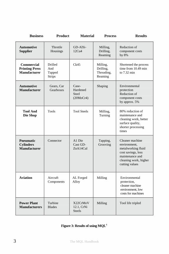
The German Ministry of Education and Research (BMBF) did a 3-year project called
“Forschung für die Produktion von Morgen” or “Research for Tomorrow’s
Production”. In this study, they looked at MQL and other “dry machining processes”
(defined as those that leave less than 2% fluid residue on the chip). Fifty-eight
studies were done involving several companies and many different materials. The
involvement of large companies such as Bosch and Daimler-Chrysler allowed
insights gleaned from the study to trickle down to small and medium sized
companies who could not afford to do the research themselves. Several of their
findings are used in this booklet, and the table below is a sample of the MQL
specific results that were found.
The MQL Handbook 2
Business Product Material Process Results
Automotive
Supplier
Throttle
Housings
GD-AlSi-
12Cu4
Milling,
Drilling,
Reaming
Reduction of
component costs
by 8%
Commercial Printing Press Manufacturer
Drilled
And
Tapped
Strips
Ck45 Milling,
Drilling,
Threading,
Reaming
Shortened the process
time from 10.49 min
to 7.32 min
Automotive Manufacturer
Gears, Car
Gearboxes
Case-
Hardened
Steel
(20MoCr4)
Shaping Environmental
protection
Reduction of
component costs
by approx. 5%
Tool And
Die Shop
Tools Tool Steels Milling,
Turning
80% reduction of
maintenance and
cleaning work, better
surface quality,
shorter processing
times
Pneumatic Cylinders Manufacturer
Connector A1 Die
Cast GD-
ZnA14Cul
Tapping,
Grooving
Cleaner machine
environment,
metalworking fluid
cost savings, less
maintenance and
cleaning work, higher
cutting values
Aviation Aircraft
Components
AL Forged
Alloy
Milling Environmental
protection,
cleaner machine
environment, low
costs for machines
Power Plant Manufacturers
Turbine
Blades
X22CrMoV
12.1, CrNi
Steels
Milling Tool life tripled
Figure 3: Results of using MQL4
3 The MQL Handbook
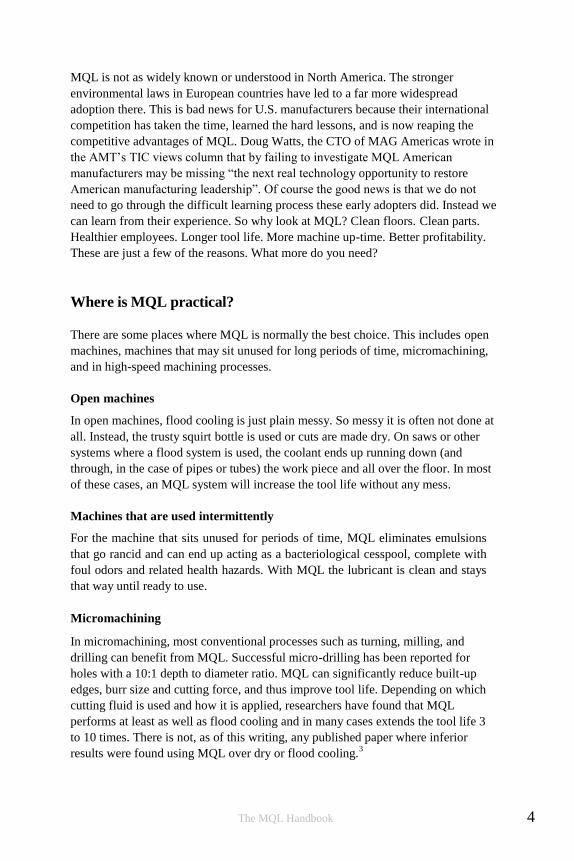
MQL is not as widely known or understood in North America. The stronger
environmental laws in European countries have led to a far more widespread
adoption there. This is bad news for U.S. manufacturers because their international
competition has taken the time, learned the hard lessons, and is now reaping the
competitive advantages of MQL. Doug Watts, the CTO of MAG Americas wrote in
the AMT’s TIC views column that by failing to investigate MQL American
manufacturers may be missing “the next real technology opportunity to restore
American manufacturing leadership”. Of course the good news is that we do not
need to go through the difficult learning process these early adopters did. Instead we
can learn from their experience. So why look at MQL? Clean floors. Clean parts.
Healthier employees. Longer tool life. More machine up-time. Better profitability.
These are just a few of the reasons. What more do you need?
Where is MQL practical?
There are some places where MQL is normally the best choice. This includes open
machines, machines that may sit unused for long periods of time, micromachining,
and in high-speed machining processes.
Open machines
In open machines, flood cooling is just plain messy. So messy it is often not done at
all. Instead, the trusty squirt bottle is used or cuts are made dry. On saws or other
systems where a flood system is used, the coolant ends up running down (and
through, in the case of pipes or tubes) the work piece and all over the floor. In most
of these cases, an MQL system will increase the tool life without any mess.
Machines that are used intermittently
For the machine that sits unused for periods of time, MQL eliminates emulsions
that go rancid and can end up acting as a bacteriological cesspool, complete with
foul odors and related health hazards. With MQL the lubricant is clean and stays
that way until ready to use.
Micromachining
In micromachining, most conventional processes such as turning, milling, and
drilling can benefit from MQL. Successful micro-drilling has been reported for
holes with a 10:1 depth to diameter ratio. MQL can significantly reduce built-up
edges, burr size and cutting force, and thus improve tool life. Depending on which
cutting fluid is used and how it is applied, researchers have found that MQL
performs at least as well as flood cooling and in many cases extends the tool life 3
to 10 times. There is not, as of this writing, any published paper where inferior
results were found using MQL over dry or flood cooling.3
The MQL Handbook 4
High-speed machining
Several studies have shown that in High-speed Machining (HSM), MQL works
better than dry machining or flood cooling. The dynamics are not fully understood,
but the basics are that the MQL output is better able to penetrate the air barrier
around the tool and the tool work piece interface than flood coolants. This results in
better lubricity than either dry or flooding and, therefore, does a better job.
General machining
MQL works well in most general machining operations. Many of the benefits will
be seen in any implementation: lower fluid use, cleaner machines, better employee
work environment, cleaner chips, and greener machining. Many shops choose to
implement MQL for these reasons alone.
Longer tool life is not always a benefit that MQL can provide. This is, typically,
because MQL is more process sensitive than flood cooling. This is discussed in
more detail later in this booklet, but to achieve gains in tool life the process must
be in the “sweet spot” where the lubricity and/or cooling of MQL keeps the tool in
a temperature zone that works well for both the tool and the material being cut.
What about the mist?
Although commonly called a mist system, machining with minimum quantity
lubrication has been shown to produce fewer emissions than flood cooling. It is,
in fact, a low-emission process. Unfortunately, when starting with MQL, many
shops think that more is better so they blast as much air as possible through the
MQL nozzles and literally create a fog or mist of lubricant in the air. This is not
MQL! A properly adjusted MQL system uses just enough air velocity to drive
the lubricant to the tool, not enough to drive it around the block!
MQL has fewer emissions and is safer than standard flood coolant. Numerous
studies measured the exposure of machine operators working around and inside of
the machine as well as the more static levels just at the machine’s control panel. In
the main study, which was conducted by the German government, the baseline was
done using flood coolants. MQL was found to never have higher levels for
aerosols, and the concentrations in more than 95% of the areas were less than half
of the flood coolant baseline values.4
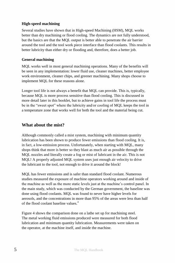
Figure 4 shows the comparison done on a lathe set up for machining steel.
The metal working fluid emissions produced were measured for both flood
lubrication and minimum quantity lubrication. Measurements were taken on
the operator, at the machine itself, and inside the machine.
5 The MQL Handbook

Em
issi
on [
mg/m
’air
]
2 0
1 8
1 6
1 4
1 2
1 0
8
6
4
0
2
M Q L
F lood
The results speak for themselves. The benefits of lower emissions are not only
seen when the work is being machined. With MQL, the parts and chips come out
dry; there are no evaporative emissions and no skin contact with metal working
fluids when handling or storing the cut or machined parts.
Operater Machine Panel Extracted Air
Measurement Point
Figure 4: Comparing flood vs. MQL emissions
MQL offers many occupational safety advantages over water-miscible MWFs. In
particular, when MQL is done with vegetable-based cutting oils, it is far safer for
employees. Not only are there fewer emissions to worry about, but vegetable oils are
naturally removed from the lungs in days instead of the months required for
petroleum based fluids. The body’s removal method is also different (expectoration
versus absorption) and studies indicate they cause no long term damage to lungs or
skin.5 Instead of petroleum emulsions, only small amounts of clean ester-based or
fatty-alcohol-based lubricants are used. Unlike emulsions, there is no need for
system cleaners, biocides and fungicides that are harmful to skin and health. Ester
oils, and especially fatty alcohols, can, however have a degreasing effect that dries
skin with prolonged direct contact. This does not necessarily mean that emission is
not needed. As discussed later in this book, proper emission control ensures the
removal of any extra emissions and the metal particles generated when cutting.
Process and ecosystem
MQL is more process sensitive than flood-cooling. There is a “sweet spot” where
MQL works well and optimal results are achieved. The good news is that this
zone is often fairly large and overlaps the machining settings used with flood
coolants. In this case, just changing from flood coolant to MQL and leaving all
the other cutting parameters the same will yield the full benefits of MQL.
The MQL Handbook 6
However, in some cases, changes have to be made to the machining process to
get it into the sweet spot. This may include changing the feed and speeds
(even increasing them), changing tool material and/or geometries and varying
the amount of lubricant applied.
Since getting the fluid in the right location is so important to MQL, nozzle position
and selection is critical. With any single MQL output, the front of the tool will block,
or shadow, the lubricant from coating the back. This leaves an area on the tool that
not effectively lubricated. Depending on the operation and the direction of cut this
may be problematic.
In operations where the tool is embedded in the work, such as turning or drilling,
getting an external nozzle to apply fluid where the cut is taking place can be
challenging. Internally fed tools and specialty nozzles are often more appropriate
than a conventional style nozzle.
Chip evacuation also needs to be considered. If the flood coolant is used to wash
away the chips, when the flood coolant goes, the chips will stay. Compressed air,
gravity, vacuums, tool geometries and several other techniques are available to aid
with chip removal. Choosing the best one for your operation is important to
maximize the success of an MQL implementation.
Optimization of the MQL ecosystem is more practical for jobs that are repeated or
that are run for a long time. This allows the cost of the initial learning to be spread
over more time. When MQL is used for short, one-off jobs it is often done for
the cleanliness and not the tool life. Adopters of MQL in a job-shop environment
should know that when the job does not fall in the MQL sweet spot their tool life
may be negatively affected.
The section How to implement MQL will go into detail on many of these items.
But in short, maximizing tool life requires the machining ecosystem be made
compatible with MQL technology. This includes ensuring that the machining
processes are appropriately adjusted and monitored.
How does MQL work?
Heat management
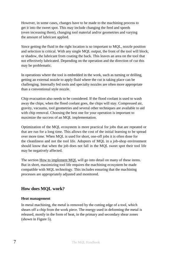
In metal machining, the metal is removed by the cutting edge of a tool, which
shears off a chip from the work piece. The energy used in deforming the metal is
released, mostly in the form of heat, in the primary and secondary shear zones
(shown in Figure 5).
7 The MQL Handbook
Workpiece
Chip Cutting
Tool
Tool
Life
Primary shear zone Secondary shear zone
Figure 5: Heat generation in metal cutting
The energy released in the primary shear zone cannot be avoided. It is a result
of the molecular bonds being broken on the work piece. Some of the heat goes into
the work piece and the rest into the chip. The friction - and resulting heat - between
the tool and the work piece in the secondary shear zone causes both the tool
and the chip to warm. The heat in this zone is one of the largest contributors
to premature tool wear. MQL, properly done, greatly reduces this heat by
lubricating the chip-tool interface.
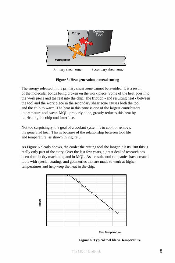
Not too surprisingly, the goal of a coolant system is to cool, or remove,
the generated heat. This is because of the relationship between tool life
and temperature, as shown in Figure 6.
As Figure 6 clearly shows, the cooler the cutting tool the longer it lasts. But this is
really only part of the story. Over the last few years, a great deal of research has
been done in dry machining and in MQL. As a result, tool companies have created
tools with special coatings and geometries that are made to work at higher
temperatures and help keep the heat in the chip.
Tool Temperature
Figure 6: Typical tool life vs. temperature
The MQL Handbook 8
To
ol Life
soo
soo
5oo
aoo
3oo
goo
zoo
too
o
A l r
Flootl Coolert
M l a t
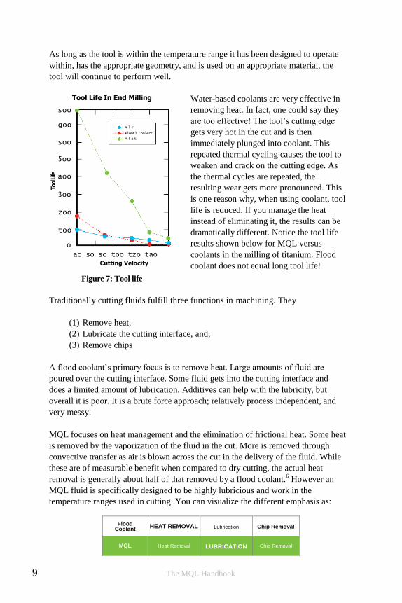
As long as the tool is within the temperature range it has been designed to operate
within, has the appropriate geometry, and is used on an appropriate material, the
tool will continue to perform well.
Tool Life In End Milling
ao so so too tzo tao Cutting Velocity
Figure 7: Tool life
Water-based coolants are very effective in
removing heat. In fact, one could say they
are too effective! The tool’s cutting edge
gets very hot in the cut and is then
immediately plunged into coolant. This
repeated thermal cycling causes the tool to
weaken and crack on the cutting edge. As
the thermal cycles are repeated, the
resulting wear gets more pronounced. This
is one reason why, when using coolant, tool
life is reduced. If you manage the heat
instead of eliminating it, the results can be
dramatically different. Notice the tool life
results shown below for MQL versus
coolants in the milling of titanium. Flood
coolant does not equal long tool life!
Traditionally cutting fluids fulfill three functions in machining. They
(1) Remove heat,
(2) Lubricate the cutting interface, and,
(3) Remove chips
A flood coolant’s primary focus is to remove heat. Large amounts of fluid are
poured over the cutting interface. Some fluid gets into the cutting interface and
does a limited amount of lubrication. Additives can help with the lubricity, but
overall it is poor. It is a brute force approach; relatively process independent, and
very messy.
MQL focuses on heat management and the elimination of frictional heat. Some heat
is removed by the vaporization of the fluid in the cut. More is removed through
convective transfer as air is blown across the cut in the delivery of the fluid. While
these are of measurable benefit when compared to dry cutting, the actual heat
removal is generally about half of that removed by a flood coolant.6 However an
MQL fluid is specifically designed to be highly lubricious and work in the
temperature ranges used in cutting. You can visualize the different emphasis as:
Flood Coolant HEAT REMOVAL Lubrication Chip Removal
MQL Heat Removal LUBRICATION Chip Removal
9 The MQL Handbook

This emphasis on lubrication means different things for different processes. In
drilling, the bulk of the heat is transferred into the tool from frictional contact rather
than the shearing of the metal.7 It is easy to see why, in drilling, MQL’s focus on
removing the frictional heat can be so effective. In operations where the chips are in
contact with the tool for a shorter time (milling, for example) the percentage of heat
from friction is less. However, in milling, the cutting edge of tool is not
continuously engaged in the cut. Since it is moving in and out of the cut, the
opportunity for thermal shock is magnified. In processes with high speeds and feeds
or short dwell times, MQL is often the best choice.
Heat can have some beneficial aspects. The work piece material generally gets easier
to cut as it gets warmer. As long as the part is not changing dimensionally and the
tool is not getting outside of its designed work zone, the heat can be helpful.6
Multiple studies on MQL have also found that different chemical reactions can occur
in a cut when sufficient heat is present.
One study found that the synthetic esters used in many of the higher quality MQL
oils react to form a protective layer on the tool’s cutting edge. This barrier means
“...the strength and wear resistance of a cutting tool can be retained which leads to a
significant improvement of tool life.” The authors go on to say that “there exists an
optimal cutting speed at which a stable protective oxide layer can be formed. When
cutting speed is lower than this speed, there is less oxide layer and the improvement
of tool life is less apparent. As the cutting speed is far beyond the optimal value, the
protective layer is absent and the thermal cracks are apt to occur at the cutting edge
due to large fluctuation of temperature.”8
The material cut can also be reactive. For example, it has been found that in
Titanium, when cut with carbide tools, TiC forms. This acts as a solid lubricant that,
like the ester barrier above, protects the tool. In dry cutting the temperature gets too
hot and this barrier burns off. It will form in flood cooling, but the thermal stresses
cause the tool to break catastrophically. In MQL, the layer forms and the tool sees
significantly longer life. This effect is, in part, what explains the tool life graph
shown in Figure 7.9
Part of heat management is considering how heat will affect the work piece. In
prolonged operations thermal expansion may affect the tolerances and dimensions
you need to set during the cut. It may dictate in what order operations are performed
to minimize the effects of part expansion. By properly optimizing for MQL, some
shops have been able to shorten the cycle time enough that the heating did not occur.
For example, one manufacturer found by moving to MQL and making the
corresponding adjustments in tools and speeds they were able to reduce the cycle for
turning threads on a nut by around 40%.10
Another was able to change tool
dimensions to account for the thermal change.10
The MQL Handbook 10

Tem
pera
ture
Incr
ease
(̊C) 3 5
3 0
2 5
2 0
1 5
1 0
5
0
So heat, when managed, can work in your favor. How much more heat is generated in
MQL? Of course it depends significantly on the cutting parameters and the materials,
but to give a general idea, the graph below shows the temperature increases after
milling 340 meters (13,385 in) in P20 steel with different lubrication types. The
observant reader may notice that there was less heat with less MQL oil. In MQL, less
is often better!
A B C D E F
Lubrication Type
A = MQL 6 mL/hr
B = MQL 12 mL/hr
C = MQL 24 mL/hr
D = Compressed Air
E = Dry Machining
F = Flood Coolant
Figure 8: Temperature increase for different lubrication techniques
Less is more
As the graph above indicates, too much lubricant, especially oil based lubricants,
may cause unnecessary heat generation and tool wear. Field experience has shown
that using too much oil reduces tool life and increases heat. Although the exact
mechanisms are not clear, it appears that after a certain amount of lubricant has
been delivered, there is no additional lubricity added by using more oil. The excess
oil is not consumed and instead acts to retain heat. It may, in fact, leave enough
residue on the chips to act as an adhesive layer. This adhesive layer increases the
tendency of chips to clump together and increases the friction associated with their
removal.
More is better
Experience has shown that the materials can often be machined with higher
speeds and feeds than with flood cooling.5 This has been seen in the high
speed machining of most materials, drilling in structural steel, and several
other applications. Sometimes the increased load creates more favorable
conditions for the tool. The graph in Figure 9 shows how, at a set fluid
output, increasing the cutting speed can decrease the temperature.
11 The MQL Handbook

Tool Temperature At Cutting Speeds
230
220
15l/min T o o l t e m p
˚C 2 1 0
2 0 0
1 9 0
1 8 0
35 l /m in
45 l /m in
Vc (m/min)
Figure 9: Temperature change at various cutting speeds
In some cases, when speeds are increased, the tool gets cooler because of the time it
takes for the heat energy to transfer to the tool compared to the time in cut.7 This is
seen more in high-speed machining.
Temperature at the cut, at moderate cutting speeds, is affected more by speed than
feed so, if the tool and cut geometry allow, adjusting the speed will have the most
impact on the cutting temperature. This in turn will reduce the temperature of the
chip and in the secondary shear zone. Just as with water based cutting fluids, a good
indication that the speed should be increased is the presence of a built-up-edge on
the cutting tool.
Faster feeds may also help when transitioning into MQL because increased feeds
generally form larger chips which, in turn, carry more heat away from the cut. The
heat generated at the primary shear line is dispersed on both sides of the line, but
the chip is also deforming and ultimately tears off. This extra work on the chip side
results in more heat in the chip; from a heat perspective it is best to keep that the
chip as large as possible then move it away from the tool and work piece as quickly
as possible.6
The sweet spot
These effects help explain the “sweet spot” often seen when optimizing for MQL.
When in the zone - where the heat at the tool cutting edge is within the design
parameters for the tool and any positive tribological effects are achieved - tool life is
optimized. When outside of these parameters, it is not. The good news is that this
zone is often fairly large.
The MQL Handbook 12
MQL
Applicator
Responsibilities
Tool
Makers
Responsibilities
Machine
Responsibilities
MQL equipment
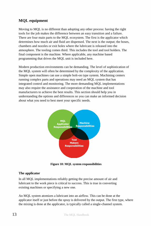
Moving to MQL is no different than adopting any other process: having the right
tools for the job makes the difference between an easy transition and a failure.
There are four main parts to the MQL ecosystem. The first is the applicator which
determines how much air and fluid are dispensed. The next is the output; the hoses,
chambers and nozzles or exit holes where the lubricant is released into the
atmosphere. The tooling comes third. This includes the tool and tool holders. The
final component is the machine. Where applicable, any machine based
programming that drives the MQL unit is included here.
Modern production environments can be demanding. The level of sophistication of
the MQL system will often be determined by the complexity of the application.
Simple open machines can use a simple bolt-on type system. Machining centers
running complex parts and operations may need an MQL system that has
integrated control and monitoring. The more demanding MQL implementations
may also require the assistance and cooperation of the machine and tool
manufacturers to achieve the best results. This section should help you in
understanding the options and differences so you can make an informed decision
about what you need to best meet your specific needs.
Figure 10: MQL system responsibilities
The applicator
In all MQL implementations reliably getting the precise amount of air and
lubricant to the work piece is critical to success. This is true in converting
existing machines or specifying a new one.
An MQL system atomizes a lubricant into an airflow. This can be done at the
applicator itself or just before the spray is delivered by the output. The first type, where
the mixing is done at the applicator, is typically called a single-channel system.
13 The MQL Handbook

Coaxial hose Single-line hose
This is because the combined mixture goes down a single hose or channel. When
the lubricant and the air are carried separately it is a dual-channel system.
In almost all cases, the dual-channel approach is preferred. By waiting to mix the
parts until they are needed you get the most uniform droplet size and spray pattern.
You also avoid oil collecting in hose bends or at changes in diameters in channels.
Dual-channel delivery eliminates dripping and other side effects of the collected oil.
Since the oil and air are mixed at the point of application, any changes that need to
be made to the mixture happen immediately. The change does not have to work its
way out to the end of a hose.
Although technically desirable, dual-channel systems are not always the most
practical. When working with internally fed systems on machines that were not
designed for MQL, it may not be possible to get a tube or hose through the spindle
for the separate channels. And since dual-channel systems tend to cost more, in some
applications, the difference in price may not be worth the added performance.
What is the easiest way of determining if a system is dual or single-channel? Look
at the output hose. Dual-channel hoses will have separate paths for the air and oil.
This may be two tubes side by side or one tube inside of another (coaxial).
Figure 11: Coaxial and Single-line hose
Some systems have tubing specifically designed for use on dual-channel MQL
systems that allow for easy adjustment of the length as well as easy routing
of a single tube.
Single-channel systems will have only one hose with no separate structure to
carry the fluid. Simple application systems are designed to be adjusted manually.
More sophisticated systems can be controlled directly from the machine control
system via an M-code, ProfiBus, or other interface. This allows the required
quantity of oil and air to be set by the program so it can be changed whenever
there is a tool or process change. They can be monitored locally through alarms
or remotely via MTConnect or OPC UA. This gives you the ability to tell when
fluid needs to be replenished or if there is a blockage preventing effective fluid
delivery.
The MQL Handbook 14

Moving the fluid
There are three basic ways applicators move and mix the fluids
through them. The simplest system is based on the venturi
principle. Air is pushed through a venturi to siphon the fluid
from the reservoir. This creates aerosol particles of
approximately 0.5 μm to 5 μm. Venturi systems are single -
channel only and have almost no moving parts. This makes them
simple and reliable. However, external environmental condition s
and variations in the incoming airf low directly affect the output;
so, although reliable, they are not particularly precise. As is true
in all single l ine systems, a venturi -based system is slow to react
to changes in settings.
Systems that can support one or more channel
are either pressure or pump-based. Pressure-based
systems use a pressurized tank to force the lubricant
through the system. The amount of lubricant
delivered is controlled through a separate
metering system. Higher quality pressure-based
systems allow separate adjustment of the tank
pressure, the output airflow and the amount of
oil injected into the airflow. These systems often Figure 12: Pressure-based system
allow several outputs to be connected and
regulated from a single tank. Pressure-based systems produce a consistent output
stream and have fewer moving parts than pump-based systems. However, even
with a regulator the pressure will vary some and most fluid’s properties change
with temperature. Like a venturi system, it is difficult to do precise adjustment
of the amount of lubricant that is delivered. Furthermore, the number of outputs
is limited by the pressure drop inherent in the design.
Figure 13: Pump-based system
Pump-based systems move the fluid using a small pneumatic or electric piston style
pump. The pump allows precise control of the fluid output though adjustments of its
stroke length and frequency. The positive displacement design ensures that exactly
the same volume of lubricant is metered out each stroke. It is the most
15 The MQL Handbook
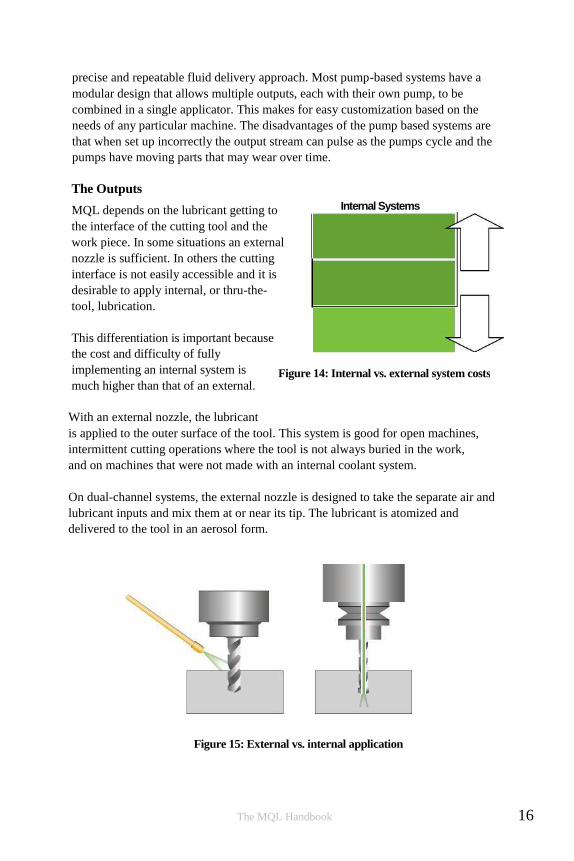
Single-Channel Systems Mix occurs outside the main spindle.
Dual-Channel Systems Mix occurs inside the main spindle near the tool.
External Systems Lubricant is fed from outside the tool
DEVICE COSTS
H IGH
L O W
$
$
Internal Systems
Figure 14: Internal vs. external system costs
precise and repeatable fluid delivery approach. Most pump-based systems have a
modular design that allows multiple outputs, each with their own pump, to be
combined in a single applicator. This makes for easy customization based on the
needs of any particular machine. The disadvantages of the pump based systems are
that when set up incorrectly the output stream can pulse as the pumps cycle and the
pumps have moving parts that may wear over time.
The Outputs
MQL depends on the lubricant getting to
the interface of the cutting tool and the
work piece. In some situations an external
nozzle is sufficient. In others the cutting
interface is not easily accessible and it is
desirable to apply internal, or thru-the-
tool, lubrication.
This differentiation is important because
the cost and difficulty of fully
implementing an internal system is
much higher than that of an external.
With an external nozzle, the lubricant
is applied to the outer surface of the tool. This system is good for open machines,
intermittent cutting operations where the tool is not always buried in the work,
and on machines that were not made with an internal coolant system.
On dual-channel systems, the external nozzle is designed to take the separate air and
lubricant inputs and mix them at or near its tip. The lubricant is atomized and
delivered to the tool in an aerosol form.
Figure 15: External vs. internal application
The MQL Handbook 16

Lubricant ai r
a i r Lubricant
tool holder
spindle t o o l
Single-Channel MQL
System
atomized lubricant in airstream
separate air lubricant supply
spindle
Dual-Channel MQL
System
tool holder
t o o l
atomized lubricant
As with external systems, single-channel and dual-channel streams can be used
with internally applied lubrication. In single-channel systems the aerosol is
generated in the applicator or just before entering the spindle. In dual-channel
systems, the air and oil are fed separately through the spindle or rotary union and
mixed when they exit the spindle or in the tool holder, to produce the aerosol
directly in front of the tool.
Figure 16: Single and dual-channel systems
Internal or External?
Low cost, simple installation and the ability to deploy conventional tools are the key
advantages of using external nozzles. However, there are several disadvantages.
Nozzles have to be manually adjusted and positioned in ways that do not interfere
with the tool or other moving parts in or around the machine. They may need to be
adjusted to accommodate different lengths and sizes of tools. The output from a
single nozzle cannot completely cover the circumference of a tool because of
shadowing effects. There are also losses due to the dispersion of the lubricant as it is
delivered to the work piece. In cases where the cutting edge is embedded or hidden,
such as when deep hole drilling, it is often wholly inadequate.
17 The MQL Handbook
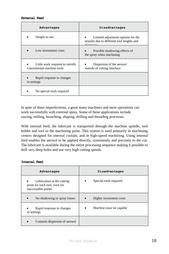
External Feed
Advantages Disadvantages
Simple to use Limited adjustment options for the
nozzles due to different tool lengths and
diameters
Low investment costs Possible shadowing effects of
the spray when machining
Little work required to retrofit
conventional machine tools
Dispersion of the aerosol
outside of cutting interface
Rapid response to changes
in settings
No special tools required
In spite of these imperfections, a great many machines and most operations can
work successfully with external spray. Some of these applications include
sawing, milling, broaching, shaping, drilling and threading processes.
With internal feed, the lubricant is transported through the machine spindle, tool
holder and tool to the machining point. This system is used primarily in machining
centers designed for internal coolant, and in high-speed machining. Using internal
feed enables the aerosol to be applied directly, consistently and precisely to the cut.
The lubricant is available during the entire processing sequence making it possible to
drill very deep holes and use very high cutting speeds.
Internal Feed
Advantages Disadvantages
Lubrication at the cutting
point for each tool, even for
inaccessible points
Special tools required
No shadowing or spray losses Higher investment costs
Rapid response to changes
in settings
Machine must be capable
Contains dispersion of aerosol
The MQL Handbook 18

spindle ________________________________________ tool holder
t o o l
mixing chamber
On both internal and external delivery, a dual-channel system will usually give the
best results. The channels should be maintained as far as possible; to the nozzle tip
or if practical almost up to the start of the tool. This allows very fast response times
to changes in output, down to about 0.1 seconds. With this short delay, no time
delays needs to be added to cutting programs to make lubrication changes.
In machines designed for MQL, the separate channels are brought to the spindle
and carried on through the spindle. Once in the spindle, the lubricant may be
carried to the tool holder through a delivery tube. The air flows through a chamber
in the spindle that surrounds the fluid delivery tube. In some specialized tool
holders, the aerosol is mixed in a special chamber located just before the tool. In
non-MQL-specific setups it is mixed somewhere near the end of the spindle itself.
The aerosol is then delivered through the tool.
Figure 17: Dual-channel system components
The delivery tube eliminates the centrifugal effects caused by the rotating spindle
and the separation of the oil out of the aerosol that happens when it hits the sides
of the spindle. This approach allows much higher spindle RPMs while still
maintaining the precision of the MQL output. It also keeps the inside of the
spindle clean since the oil does not come into contact with it. It is important to
ensure that the rotary union used is able to run with MQL. Many unions are
designed to be used with flood coolants and use the coolant as a lubricant. When
running in dual-channel mode, the union is essentially running dry and if it isn’t
designed for this it may experience premature wear.
The description above is the best case scenario; it is how things work when the
machine, tool holder and tool are all designed for MQL. Unfortunately, putting all
this in place isn’t always easy. So, although desirable, practical considerations may
make achieving this neither feasible nor cost effective. It is, however, always
possible to run the dual-channel line to the spindle.
19 The MQL Handbook

On machines that are not designed for internally fed coolant, a coolant inducer
would have to be used to get the aerosol down to the tool. At this time, there are no
known dual-channel MQL coolant inducers and from the inducer onward it would be
would be a single-channel.
Even if the machine was designed for internal coolant, it does not mean it will work
seamlessly with dual-channel MQL. As mentioned before, some spindles have a
rotary union that requires lubrication so the mixture must be done at the union to
allow it to be lubricated. Some machines do not have room in the fluid channel for a
separate oil line so, again, the aerosol needs to be mixed before the channel. Some
have room for a partial fluid channel but not all the way to the tool holder. In these
cases a shorter channel may be used. Some spindles have sharp angles inside that
make running a separate line impossible.
Single-channel MQL can almost always be made to work even though it is not
always as simple as one would wish. Some machines have chambers with sharp
edges and cavities where fluid can collect and cause drips. Others have large changes
in the cross sectional area of the chamber that lead to air velocity changes which
slow down the response time of the lubrication system.
As you can see, if planning on using internal MQL it is a very good idea to talk to
the machine manufacturer and the maker of the MQL applicator to ensure all the
pieces will work as desired and provide the needed accuracy and control.
The MQL Handbook 20

A short summary of the difference of the two internally fed options is below.
Single-channel System Dual-channel System
Can switch between flood
and MQL
Good response for switching
between tools and cuts in machining
centers
Simple routing of aerosol
stream to multiple spindles
Supplying multiple spindles from
one unit more complicated
May lubricate rotary
unions and other internal parts
Requires a rotary union that can run dry
Standard tool holder for
internal fluid feed possible
Current MQL specific tool holders
are only HSK (Hollow taper shank) style.
Fe
ed through complicated channels
usually possible
Difficult to route through
complicated channels
Effective lubricant
delivered effected by RPM
Lubricant delivered independent of RPM
Reaction time to change
lubricant and air relatively slow
Fast reaction time to changes in
lubricant and air flow
More air pressure needed
(> 4 bar or 60 psi)
The lubricant
Minimum quantity lubrication is a total-loss lubrication method rather than the
circulated lubrication method used with emulsions. This means only new, clean
lubricant is used. Biocides, fungicides and other additives are eliminated. A good
MQL fluid has very high lubricity and thermal ratings to withstand the high
thermal and mechanical loads present. There are generally two types of fluids
used: synthetic ester oils and fatty alcohols formulated for the proper range of
vaporizations and flash points.
Types of MQL fluids
Synthetic esters are preferable for machining processes where the lubricating effect
is of prime importance. This is the case for most materials and operations. These
lubricants are designed for low viscosity while maintaining a high boiling and flash
point. This gives better results under load and generates fewer vapors than
21 The MQL Handbook
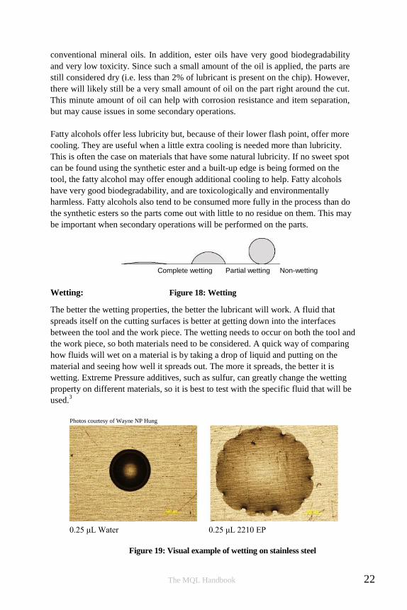
Photos courtesy of Wayne NP Hung
conventional mineral oils. In addition, ester oils have very good biodegradability
and very low toxicity. Since such a small amount of the oil is applied, the parts are
still considered dry (i.e. less than 2% of lubricant is present on the chip). However,
there will likely still be a very small amount of oil on the part right around the cut.
This minute amount of oil can help with corrosion resistance and item separation,
but may cause issues in some secondary operations.
Fatty alcohols offer less lubricity but, because of their lower flash point, offer more
cooling. They are useful when a little extra cooling is needed more than lubricity.
This is often the case on materials that have some natural lubricity. If no sweet spot
can be found using the synthetic ester and a built-up edge is being formed on the
tool, the fatty alcohol may offer enough additional cooling to help. Fatty alcohols
have very good biodegradability, and are toxicologically and environmentally
harmless. Fatty alcohols also tend to be consumed more fully in the process than do
the synthetic esters so the parts come out with little to no residue on them. This may
be important when secondary operations will be performed on the parts.
Complete wetting Partial wetting Non-wetting
Wetting: Figure 18: Wetting
The better the wetting properties, the better the lubricant will work. A fluid that
spreads itself on the cutting surfaces is better at getting down into the interfaces
between the tool and the work piece. The wetting needs to occur on both the tool and
the work piece, so both materials need to be considered. A quick way of comparing
how fluids will wet on a material is by taking a drop of liquid and putting on the
material and seeing how well it spreads out. The more it spreads, the better it is
wetting. Extreme Pressure additives, such as sulfur, can greatly change the wetting
property on different materials, so it is best to test with the specific fluid that will be
used.3
0.25 μL Water 0.25 μL 2210 EP
Figure 19: Visual example of wetting on stainless steel
The MQL Handbook 22

Em
issions
5 0
4 0
3 0
2 0
1 0
0
Cutting zone
Viscosity
Generally, better wetting properties mean lower fluid viscosities. Unfortunately,
lower fluid viscosities increase the tendency for the fluid to generate a mist. The
following chart shows measured emission levels at the cutting interface and at the
extraction point for different viscosities on a drill. To help keep the emissions to a
minimum it is suggested that products with higher viscosities and flash points (>
150°C or 300°F) are used.
Emissions
8 17 19 32 48 65 88 100
Viscosity
Figure 20: Emissions at cutting area based on viscosity
In selecting an MQL fluid, one needs to balance the wetting with the emissions.
This balance point will be different for open versus closed machines and on closed
machines with emission control devices versus those without. However, a high
quality MQL specific fluid will work well with a minimal amount of misting.
Tools and tool holders
Not surprisingly, the tool is an important piece of the total MQL ecosystem. Tools
that were selected based on the conditions found in wet machining may not be best
for use with MQL. MQL is based on reduced heat development and rapid heat
dissipation via the chips instead of rapid cooling by fluid. MQL compatible tools
should be designed to work at higher heat levels and the geometry of the tool
should be optimized to transfer the chips away from the tool as quickly as possible.
This is in contrast to tools designed for wet cutting that may be optimized for
maintaining an edge through repeated thermal cycling. For example,
High Performance Cutting (HPC) drills are characterized by high-performance
materials, MQL-compatible coatings and geometries that assist with chip removal.
23 The MQL Handbook

Figure 21: Thru-the-tool exit holes
Some tool coatings are more MQL friendly. Hard material layers help to thermally
insulate the tool and polished tool surfaces help minimize the friction. Geometry,
such as rake and clearance angles, should be designed to create, break, and move
chips away from the tool. For example, in drilling, the optimal chip is short, but with
at least one spiral. Tool manufacturers who offer MQL-compatible tools can give
specific guidelines in selecting the right tool for the required process, and give
material-specific and tool-specific cutting parameters (e.g. feed, cutting speed).
One manufacturer of nuts, using a two-spindle horizontal lathe, tried converting to
MQL by simply switching from a flood to an MQL applicator. Unfortunately this
simple switch did not put this operation in the sweet spot. The resulting heat in the cut
kept them from meeting the required tolerances on the threads. However by selecting a
more appropriate tool for the new process they cut their cycle time down by 35%. This
shortened time kept the part cool enough that the tolerances could be maintained and,
as would be expected with an increase like that,
gave them a substantial boost to their production
capacity.10
In internally fed tools, there are several elements
in the tooling that should be considered. The
interface between the lubricant feed and tool/tool
holder should be sealed in order to prevent any
lubricant from escaping into the clamping area of
the chuck or the interior of the machine. The
lubricant holes should be designed to uniformly
coat the cutting edge and avoid any blind spots.
An elliptical channel that increases the cross
section area is often desirable.
Current tool holders designed for MQL are HSK style and have a mixing chamber
built into them. Non MQL holders often have sharp angles on the internal edges.
Just as in the spindle, the centrifugal force pushes the aerosol to the sides which
cause the oil and air to separate and can result in dripping and unwanted oil build
up. Also the large change in diameter from the spindle channel to the cavity in the
tool holder can cause airflow velocity changes that make it more difficult to
maintain and change the output at the tool.
The machine
Depending on the machine requirements and how far you want to take it,
optimizing for MQL can range from doing nothing to making extensive
modifications. With open machines using external nozzles or machines using
single-channel MQL there is usually little to do outside of attaching and
connecting the applicator, routing the hoses, and positioning the nozzles. If
the machine is to use an internal dual-channel system the changes to the
spindle can be more involved.
The MQL Handbook 24
MQL-Ready Main Spindle ( 1
or 2 channel )
Extraction System for emissions &
metal dust
Smooth Walls w/incline of at
least a 35˚ angle
Large chip chute
Chip Conveyor
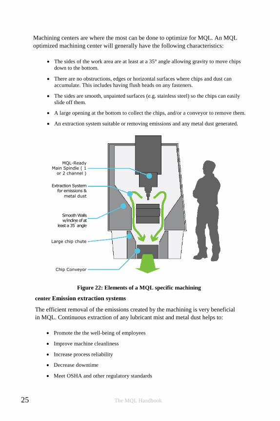
Machining centers are where the most can be done to optimize for MQL. An MQL
optimized machining center will generally have the following characteristics:
The sides of the work area are at least at a 35° angle allowing gravity to move chips
down to the bottom.
There are no obstructions, edges or horizontal surfaces where chips and dust can
accumulate. This includes having flush heads on any fasteners.
The sides are smooth, unpainted surfaces (e.g. stainless steel) so the chips can easily
slide off them.
A large opening at the bottom to collect the chips, and/or a conveyor to remove them.
An extraction system suitable or removing emissions and any metal dust generated.
Figure 22: Elements of a MQL specific machining
center Emission extraction systems
The efficient removal of the emissions created by the machining is very beneficial
in MQL. Continuous extraction of any lubricant mist and metal dust helps to:
Promote the the well-being of employees
Improve machine cleanliness
Increase process reliability
Decrease downtime
Meet OSHA and other regulatory standards
25 The MQL Handbook

Unlike wet machining, MQL extraction systems may have to remove metal dust as
well as aerosols. The extraction system should be designed to handle this dust to
avoid premature failure. This usually takes the form of a screen in front of the inlet
of the extraction system. The flow rate in the extraction pipe work should also be
high enough to prevent dust accumulations from forming inside. As a rule of thumb
the flow rate should be greater than 20 m/s (65 fps).
The pressure inside the machine should be slightly less than the outside pressure to
create an inward airflow through any openings so no emissions escape when the
doors are opened or through other openings.
However, if the flow rate is too high at the extraction point, the chip protection
screen in front of the extraction inlet can clog. If needed, dust can be separated
from large chips by installing a deflector plate and droplet separator.5
Unlike conventional extraction systems in wet machining where air is extracted
through the upper part of the machine, MQL emission extraction is often more
effective closer to the work. Some machine manufacturers offer extraction openings
that are incorporated into the spindle head allowing extraction to take place very
near to the cutting zone. The emission extraction systems may also be done near or
at the chip removal area. This has the advantage of bringing any dust and chips
down to the removal area.
Air curtains or blow offs along the inner wall of the machine may also be used to
keep the sides clean and improve chip removal. This prevents caking and crusting of
metal dust on surfaces.
How to implement MQL
Training
Training is first in this list because it is one of the more important, and often most
overlooked elements to successfully implementing MQL. Most machinists are
familiar with flood coolant and how it works but many of the habits formed when
working with wet machining are not helpful when using MQL. In fact, they can be
harmful.
The MQL lubricant spray, even when externally applied, is often nearly invisible.
Adjusting the output to the point where you can see it does not help. Instead, it has
the potential for filling the work area with mist, it wastes fluid, and it likely takes
the process out of the sweet spot. Blasting too much fluid with too much air
pressure is probably the most common mistake when first implementing MQL. The
cycle perpetuates itself because when the initial blast doesn’t work and the
The MQL Handbook 26

knobs get turned even higher. More is not necessarily better! Training on
MQL for all operators on all shifts is important to keep the system working
and running smoothly.
Basic MQL training should include how to properly set and adjust the system,
a review of the principles behind the technology and an explanation of the health
and safety benefits of a properly adjusted system to the machine operators.
This training helps ensure the overall success of MQL and assists in a seamless
roll out of the new technology.
Considerations when setting up the applicator
The applicators themselves are generally easy to install. They either bolt directly to
the machine or are mounted with magnets. Most will have an electric solenoid valve
to control the on/off operation. This valve needs to be wired into the appropriate
circuit on the machine so it will turn the applicator on at the appropriate time. This
may be into the trigger on a saw or into the M-codes relays on a more complex
machine. An air supply will need to be connected to the unit (typically requiring 480
to 690 kPa or 70-100 psi) and any tank or fluid reservoir filled with an MQL fluid.
Pumps may need to be primed and hoses filled so that the fluid is ready to be
dispensed. These are straightforward tasks and are usually quickly completed.
Care should be taken when running the fluid lines to ensure that they will not be hit
any moving parts and that hot chips will not be landing on them. Many systems use
polyurethane hoses and the hot chips can burn holes in them. As mentioned earlier, if
you are using an evacuation system on a machining center, the airflow around the
hose entry points should be minimized or eliminated to maintain the desired flow
pattern in the machine.
More advanced application units have monitoring systems that will also need to be
connected. These may include low-level sensors that will sound an alarm or shut off
the machine when the fluid level hits a predetermined point and flow sensors to
ensure fluid is being delivered. Since the output of the system is usually invisible to
the operator, he or she may not notice when the fluid is gone and may unknowingly
begin cutting dry. A fluid flow sensor can help avoid potentially costly mistakes.
More challenging is establishing the proper setting for the amount of air and fluid to
be applied. Like all machining settings, there is a definite element of “art” to the
“science”. MQL is no different than wet machining in that proper settings are
dependent on the tool type, tool materials and coatings, tool size, tool geometries,
tool wear, cutting geometries, cutting speeds, cutting feeds, work piece material
properties, chip formation dynamics, machine rigidity, and so on. Since there is no
way to precisely account for all of these the following sections of this booklet will
give general rules of thumb. You will need to do some experimenting and tweaking
to find the sweet spot for your particular job.
27 The MQL Handbook

The goal of MQL is simple: apply just enough fluid to fully lubricate the operation
with the least amount of airflow needed to carry the droplets to the tool. This keeps
the cut and tool well lubricated while minimizing any excess aerosol that could be
generated. Some factors to consider:
There are two places that need to be lubricated: The tool/work piece
interface and where the chips come in contact with the tool. On a tool
with a large chip contact surface, like a drill, more area needs to be
covered than on a tool with relatively little chip contact.
Airflow/droplet speed. Too slow and the fluid does not make it to the tool;
too fast and droplets can bounce off the intended target or are blown
throughout the shop.
The longer the distance that the nozzle needs to spray, the more airflow is
needed to carry aerosol and the higher the likelihood of an unwanted mist
being generated. In closed machines, an extraction system can help with this.
In open systems, putting the nozzle closer to the cut helps. This can often be
done by creating a special nozzle that places the spray just where it needs to
be.
Different fluids form different droplet sizes, which will weigh different
amounts and therefore require different airflows to carry them. You will
need to determine the optimal position and flow on a per-fluid basis.
Tool RPMs affect how long the surface of the tool is facing the nozzle,
how much force is trying to throw off the fluid, and the strength of the air
barrier around the tool. After a certain point, the fluid will not get-to or
stick-well-to the tool. MQL works far better than water based emulsions in
penetrating this barrier and is one of the reasons it is usually the best
option in high-speed machining.
Figure 23: Airflow around high speed tool
The MQL Handbook 28
Rules of thumb for external nozzles
Unless you are working with very small chips, as in micro-cutting, trying to blow
the chips away with air from the fluid delivery spray will only create a fog and use
more fluid than is necessary. Use a separate chip removal approach, such as an air
blow-off or a vacuum, to remove chips if needed.
If practical, moving the nozzle closer to the work will allow lower air volumes to
be used.
On pump-based systems, ensure the system is adjusted so that any
pulsing from the output is eliminated. A good way to do this is move a
piece of cardboard in front of the nozzle as it is spraying and check that
the output is consistent in size; There should be no “spitting” of larger
droplets. See the Coolubricator system adjustment the video at
www.unist.com for an example of how to make these adjustments on a
manually-controlled system.
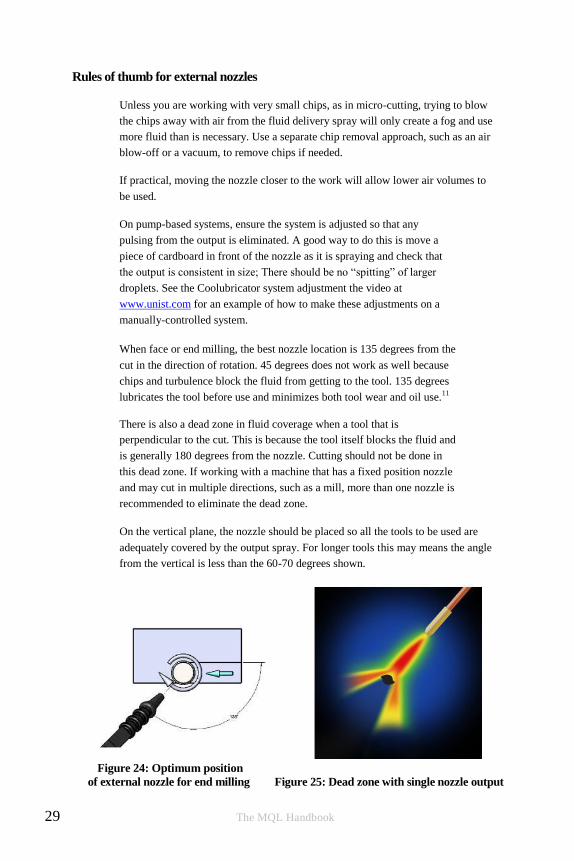
When face or end milling, the best nozzle location is 135 degrees from the
cut in the direction of rotation. 45 degrees does not work as well because
chips and turbulence block the fluid from getting to the tool. 135 degrees
lubricates the tool before use and minimizes both tool wear and oil use.11
There is also a dead zone in fluid coverage when a tool that is
perpendicular to the cut. This is because the tool itself blocks the fluid and
is generally 180 degrees from the nozzle. Cutting should not be done in
this dead zone. If working with a machine that has a fixed position nozzle
and may cut in multiple directions, such as a mill, more than one nozzle is
recommended to eliminate the dead zone.
On the vertical plane, the nozzle should be placed so all the tools to be used are
adequately covered by the output spray. For longer tools this may means the angle
from the vertical is less than the 60-70 degrees shown.
Figure 24: Optimum position
of external nozzle for end milling Figure 25: Dead zone with single nozzle output
29 The MQL Handbook

Figure 26: Vertical position of external nozzle
In peripheral milling, or when the tool is parallel to the work piece, the
dead zone starts closer to 100 degrees from the nozzle. The nozzle should
be placed close to horizontal spraying the tool before it enters the cut to
fluid delivery. It is placed before entering the cut, not on the back side, so
no chips or turbulence interrupts the aerosol flow.3
Figure 27: Optimum position of external
nozzle for peripheral milling
The nozzle should be placed so that it is spraying the tool/work piece
interface. In some cases this may mean the nozzle is attached to the bed
or the work piece holder. In other cases it can be connected to the
spindle arm.
Figure 28: Nozzle positioning
Traditional needle-style nozzles are made in a few different styles.
They may be made of plastic (e.g. Loc-line®), softer more flexible
metal, or harder metal.
The MQL Handbook 30
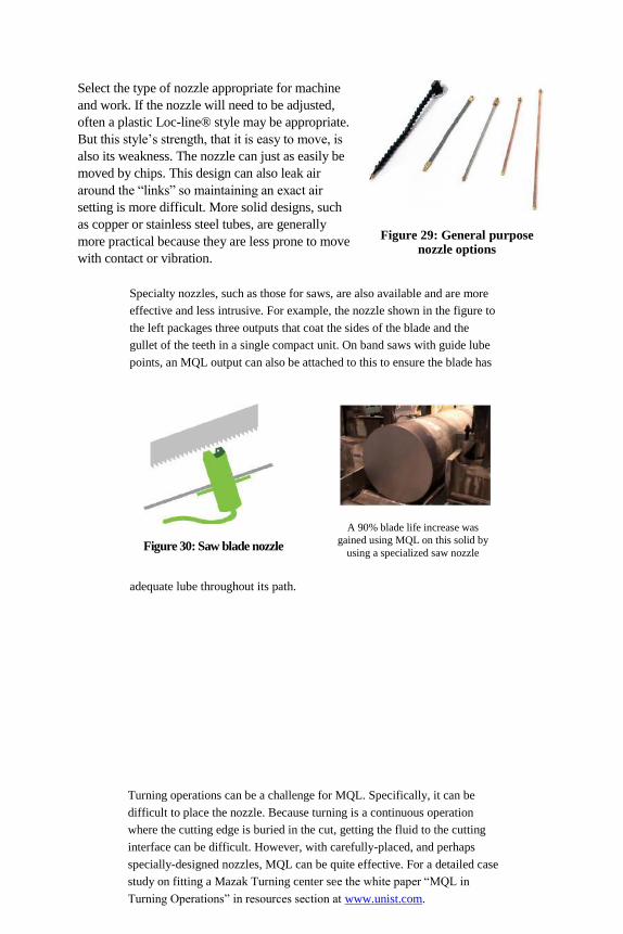
A 90% blade life increase was
gained using MQL on this solid by
using a specialized saw nozzle Figure 30: Saw blade nozzle
Select the type of nozzle appropriate for machine
and work. If the nozzle will need to be adjusted,
often a plastic Loc-line® style may be appropriate.
But this style’s strength, that it is easy to move, is
also its weakness. The nozzle can just as easily be
moved by chips. This design can also leak air
around the “links” so maintaining an exact air
setting is more difficult. More solid designs, such
as copper or stainless steel tubes, are generally
more practical because they are less prone to move
with contact or vibration.
Figure 29: General purpose nozzle options
Specialty nozzles, such as those for saws, are also available and are more
effective and less intrusive. For example, the nozzle shown in the figure to
the left packages three outputs that coat the sides of the blade and the
gullet of the teeth in a single compact unit. On band saws with guide lube
points, an MQL output can also be attached to this to ensure the blade has
adequate lube throughout its path.
Turning operations can be a challenge for MQL. Specifically, it can be
difficult to place the nozzle. Because turning is a continuous operation
where the cutting edge is buried in the cut, getting the fluid to the cutting
interface can be difficult. However, with carefully-placed, and perhaps
specially-designed nozzles, MQL can be quite effective. For a detailed case
study on fitting a Mazak Turning center see the white paper “MQL in
Turning Operations” in resources section at www.unist.com.

Figure 31: Nozzle on a turning center
31 The MQL Handbook

32
Rules of thumb for MQL fluids
How much fluid to use depends on the size of the tool, the contact area
between the chip and tool, and the time in the cut. As a general rule of
thumb, fluid use of 5 to 80 ml (0.2 – 2.5 oz.) per hour of cutting time on
tools less than 40 mm (1.6 in) in diameter seems to keep chips dry and give
good results. Always use the least amount needed to achieve maximum tool
life. Remember that oftentimes, less is more.
If chips are sticking to the tool, you are putting on too much oil. It is
acting as a chip adhesive more than a lubricant.
If the chips or the work piece material is welding to the material, or you
are getting a built-up-edge, you need to adjust the fluid, try a different
speed setting, or change the tool. There is too much heat.
The fluid output should be virtually invisible. If you see a mist spraying
from an external nozzle, you will likely see fogging in the plant.
Make sure the fluid will wet your cutting tool and work piece materials by
doing a droplet spread test. Apply droplet to a clean tool or work piece
surface. The surface must be clean. Use degreaser or alcohol to clean and
wait till the surface is dried. If it does not wet, then you will not see the
lubricating benefits of the fluid – no matter how much of it you put on.
You only need to confirm this once when using a new tool coating or work
piece material.
Experience shows that the best results with lubricants (ester or fatty
alcohol) are achieved at a viscosity range of 10 to 50 mm2/s (0.016 to
0.77 in2/s) and in some cases up to 100 mm2/s (0.155 in2/s) at 40 °C
(104 °F). Higher viscosity limits should be discussed with the MQL
system manufacturer to ensure they will spray correctly. Lower viscosity
fluids tend to mist.
It should be determined if the thin, post-machining residual film left by
MQL offers satisfactory corrosion protection or whether additional
corrosion protection is necessary.
The choice between an ester oil or a fatty alcohol is dependent on the
process and materials. One study found that when end milling hardened
steel at lower speeds, the ester oil gave the best results. At higher speeds, a
built-up-edge was formed and the alcohol gave better results. The choice
should be made based on the material of the work-piece, the material and
coating of the cutting tool, and the speeds/feeds of the cutting operation.
The MQL Handbook

Some fluids that are not suitable for MQL
Water-miscible metalworking fluids. These do not offer the proper
lubricity or flash point for use in MQL. Also any biocides in the fluid
may get into the air and can be a safety issue.
Lubricants with additives containing organic chlorine or zinc should be
avoided. They often react at the temperatures found in MQL machining
and cause harmful byproducts.
Natural oils and greases. Natural Esters (rape seed oil, etc.) will lubricate but are
prone to oxidation and in a relatively short time gum up the machine and
everything else they come in contact with. Note this does not apply to the
synthetic esters derived from these oils, but those found in the unprocessed oils.
Mineral oil-based products with high aromatic compound content.
Material
Gray cast iron (e.g. GG 25- GGG 40) works very well with MQL since
the graphite component in it acts as an additional lubricant. Further,
measurements show that in both milling and drilling a significant
reduction of the temperatures can be achieved with the increase of feed
rate. The tool geometry has a very high influence on the heat generated.
When cutting cast iron or other materials that may form a dust
consideration must be given to the dust removal in advance of
implementing MQL. Flood coolants help keep down the dust as well as
providing some lubrication. On an open system, a vacuum or other means
of capturing the dust will likely need to be installed when moving to
MQL.
Non-ferrous metals (e.g. aluminum with up to 1% Si) and steel
materials up to 800 MPa tensile strength (e.g. free-cutting steel,
quenched and tempered steel CK 45) cut very well.
Even traditionally difficult-to-cut materials can be machined with
minimum quantity lubrication if the process is properly designed. With
proper chip evacuation, sawing Inconel has proven to work well. In
high speed and micromachining with MQL on titanium has been shown
to work better than dry or with flood coolants. Specifics will change
based on each job’s particulars, but even with more exotic materials
MQL can yield substantial improvements.
33 The MQL Handbook

Milling in Ti-6Al-4V worked very well because the carbide tool-material combined
with MQL causing the formation of a sustainable layer of Titanium Carbide (TiC)
that acted as a friction-reducing agent with a solid lubrication effect and minimized
the other wear mechanisms. With this, at the same cutting speed, the tool life
achieved by using MQL was significantly longer than that by the other lubrication
methods.9
Some metals have proven to be more difficult. For example, heavy cutting of
copper can be problematic because the heat dissipation is insufficient.
Problems may also occur when cutting magnesium due to the flammability
of the chips and dust.
Tools
In MQL, as in all cutting, the two largest causes of tool wear are mechanical and
thermal. These are often related since high temperatures can cause more mechanical
wear and mechanical issues can cause high temperatures. Proper tool selection can
help minimize these issues and prolong tool life.
Tools that are designed for dry cutting typically work well with MQL.
Tools for flood coolant may be optimized to resist the thermal shock
associated with that process where tools for dry machining are often
designed to run at a higher temperature.
For the machining of high-strength steels, the use of a multi layer coating is
recommended, especially those with a TiAlN base layer. This coating
significantly increases the temperature range allowed. This coating has
shown good results on titanium, aluminum and nickel alloys, stainless
steels, alloy steels, and Co-Cr-Mo. A small layer thickness helps contribute
to achieving stable process conditions.
One manufacturer, using a TiAlN coating on tempered steel was able to move from a
speed of 150 m/min (492 ft/min) to 250 m/min (820 ft/min) while holding a
roughness of 3 – 5.2 microns.10
Another manufacturer cutting internal threads on ball screws had a tool specially
designed for their MQL cutting operation. They were cutting 34CrNiMo6 steel
and by using finite-element analysis in their tool design and adding a TiAlN multi
layer coating created a tool that allowed cutting with MQL that cut their
processing time from 12 hours to 3 hours per part.10
The MQL Handbook 34
Still another manufacturer who drills holes into unalloyed structural steel (ST 52-3
1.0052) for spindles in vices and metal shears determined that by using a fine grain
TiN coated carbide tool instead of HSS, they could use MQL and increase cutting
speed by a factor of 5. They also selected a drill with a larger flute and side rake angle
so the drilling process was efficient even at higher cutting speeds. The average
surface roughness was around 8 to 10 microns, well below their 25 micron limit.10
Tools for MQL may also be designed to break the chips and move them away
from the tool more quickly. Chip size (e.g. in roughing vs. finishing) also may
affect the need for coatings because of how much heat the chips can absorb.
Tools that generate smaller chips tend to need a coated tool more than those
that create large ones.
Although these tools may cost more, using the right tool will allow the machines to
run as fast, or faster, while holding very tight tolerances and reaping the benefit of
MQL surface finish improvements.12
Chips
Chip removal in MQL is different than in flood cooling. In some ways it is harder;
there is no fluid to wash chips away from the cut. In other ways it is better because a
system designed for MQL uses air, gravity, or other means to carry the chips away in
a clean and green manner.
Fast and complete removal of chips and metal dust from the workspace is
important. Hot chips in contact with the tool or the work piece will
increase the heat at that point. Chip accumulation and residues in the
work area (e.g. on the work pieces and machining equipment) should be
avoided as much as possible.
Chip disposal can often be accomplished through work space design.
When practical, using gravity to move the chips is a proven simple
method. In enclosed machines the chips should fall on to steeply inclined
metal siding into a collector or onto a conveyor. Projecting edges and
horizontal surfaces should be avoided.
Position of the work piece can also help with chip removal. A suspended
work piece works well on a vertical lathe. In machining centers, using a
pivot axis may allow the work piece to be suspended and rotated so that
the chips fall from it.
Another option for chip evacuation is an air blow-off. Compressed air can
be used to blow the chips away from the work area. Pulsed air often works
well for this and also minimizes air consumption. When using an air blow-off,
consideration should be given to the emissions and metal dust that will also be
blown. The use of an emission system can help alleviate any issues associated with this.
35 The MQL Handbook

When using air, it is recommended that a separate air blow-off nozzle be
used and not the nozzle that delivers the MQL fluid. Except in cases where
the chips are very small or very fine, such as in micromachining, the air
volume needed to move the chips is much higher than that needed to deliver
the fluid. Trying to use one nozzle for both tasks will likely end up doing
neither very well.
What does moving to MQL mean in terms of overall effectiveness?
MQL can have positive impact on Overall Equipment Effectiveness (OEE) as well.
One example of this is Ford in its Van Dyke Transmission plant. They adopted
MQL and saw many of the machining specific advantages that have already been
discussed at length. But they also found secondary advantages significantly impact
equipment effectiveness and overall operations efficiency. Ford estimates that the
total cost of ownership with MQL, based on machine cost, downtime, maintenance,
floor space, electricity usage, coolant management and related factors, decreased by
13%. Availability of the machine is increased because the electronics on the
machines last longer and have fewer nuisance faults. This improved machine up
time from 50-60% to 80-90%. CMMs could be placed on the shop floor near the
machines and did not need enclosures. Their aluminum chips could go straight to
the recycler without secondary cleaning operations being needed. The plant’s floors
could be made flatter since there was no need to engineer floor drainage systems,
and assembly could be moved closer to the machining cells greatly reducing part
travel throughout the facility.12
These highlight some of the advantages of implementing MQL that go beyond
cutting and to the machine and the plant itself. Increasing machine up-time and
reducing maintenance are great ways of improving OEE and your bottom line.
Conclusion
Hopefully the MQL handbook has given you a better idea of what MQL is and how
to implement it. It is not always as simple as just plugging in a lubrication system,
but it does offer significant advantages to the business, the employees and the
environment. It cleans up the plant, often improves tool life and surface finish,
increases mean time between failures on machines with electronics, and
dramatically reduces fluid related costs. If these are important to your operation,
then perhaps this would be a good time to give MQL a try.
The MQL Handbook 36

Appendix 1: Resources
Unist product information: http://www.unist.com
Unist videos: http://youtube.com/user/UNISTInc
Unist product literature: http://www.unist.com/info-support/product-literature/
Appendix 2: Examples of successful MQL settings and results4
Material Operation Parameters Results
Steel ASSAB
718 HH Low Speed
Milling
8.5 ml/hour (0.29 oz/hour)
fluid flow rate
Cutting speeds between 75-125
m/min (246-410 fpm)
Lower cutting forces,
thermal stresses and
burr formation than
flood coolants.13
NAK80 hardened
steel Milling 10 ml/h fluid
flow rate
Speeds between 150-250 m/
min (492-820 fpm)
Better results than
flood cooling, and the
benefits increased as
the speeds increased.14
Ti-6Al-4V Milling 10 ml/h (0.33 oz/hr) fluid
flow rate
Carbide insert
Significantly better
tool life and lower
cutting forces
compared to flood
coolants, especially
when feed rates were
larger than 0.08mm/
tooth.9
Micro MH2.
HB200-220 D2.
HB180-200
(475 mm solid)
Sawing on
a Kasto
Twin A4
Oil consumption 19.42 ml/ hour (0.65 oz/hr)
12mm per minute (4.1 ipm)
26%-90% increase in blade life.
10
37 The MQL Handbook

AlMgSi1 Milling Roughing end mills VHM/
TiAlN, d = 8.0 mm (0.31 in)
Finishing pockets mills - VHM/
TiAlN, d = 5.0 mm (0.196 in)
Cutting parameters: Rough vc =
340 m/min (1115 fpm), fz = 20
μ
edge processing mills - VHM /
TiAlN, d = 3.0 mm (0.12 in)
finishing vc = 250 m/min (820
fpm), fz = 15 μ;
edging vc = 220 m/min (721
fpm), fz = 12 μ
Successful MQL
milling of Aluminum Piston.
10
X 5 CrNi 18 10,
material no. 1.4301 Sawing Bi-metal saw blade 27 x
0.9; M2 uncoated.,
Standard tooth; Standard
set, 5 - 8 tpi
Sawed face roughness
of 27 microns was
maintained, MQL
successfully
implemented
AlMgSi0.5,
polyamide 6.6,
PUR foam
Sawing KSB Ø315x3.0x40, HSS, 240
teeth
Cutting parameters Vc = 2866
mm/min (112 ipm);
vf = 2274 mm/min (90 ipm)
Met roughness goals
of 10.3 to 14.0
microns on AL and
10.1 to 12.6 micron on
foams.10
Unalloyed
structural steel
(ST 52-3 1.0052)
Drilling Speed 150 m/min (5905 ipm), TiN
coated carbide tools 5X increase in speed rate, improved
surface finish.10
Steel (42CrMo4) Drilling Vc = 250 m/min (820 fpm)
f = 0.1 mm (0.004 in)
Rz ~ 3.0 to 5.2
microns
Steel (16MnCr5) Centering
(Drilling)
Tool: D = 6.3 x 20 mm
(0.25 x 0.79 in)
N = 500/min
Vf = 50 mm/min (1.97 ipm)
1200 centers
Steel (16MnCr5) Drilling Stepped drill D = 6.8 x 10 x 28.5
(0.26x0.30x 1.12 in)
N = 2 800/min
Vf = 504 mm/min (19.85 ipm)
2400 holes
The MQL Handbook 38

Steel (16MnCr5) Reaming Tool D = 7 H8
N = 690/min
Vf = 152 mm/min (6 ipm)
1200 operations
Steel (St38MnVS5) Drilling HSS-Drill, D = 14.5 mm (0.57
in)
N = 330/min
Vf = 52.8 mm/min (2.07 in)
500 holes
Steel (St38MnVS5) Counter-
sinking
HSS-countersink 90°,
N = 90/min
Vf = 5.2 mm/min (0.20 in)
960 operations
Steel (St38MnVS5) Threading Tap M16 x 1.5 (0.62 x 0.059
in)
N = 90/min
Vf = 135 mm/min (5.31 ipm)
500 threads
Al Si 7 Mg Sawing Band Saw > 2000 cuts
Al Si 7 Mg Milling Surface mill Approx. 6000
Steel (CK 45) Impact
drilling
HSS-Drill, D = 14 mm (0.55
in)
N = 200/min
Vf = 40 mm/min
100 – 150 holes
Al Si 10 Mg Milling End mill
N = 4 000/min
Vf = 1200 mm/min (47.25
ipm)
Approx. 105000
Al Si 10 Mg Milling Surface mill Approx. 3500
Al Si 10 Mg Sawing
Approx. 4500
Al Si9 Cu3 Deep hole
drilling
5000 holes
39 The MQL Handbook

Sources
1Standards committee tools and clamping devices (FWS) working committee.
“DIN 69090-1 MQL Maching Technology-Part 1.” Terms and Definitions.
(Article), DIN 69090-1:2011-12, (December 2011)
2 DeVries WR, Murray SF. (1994) Tribology at the cutting edge: cutting and
grinding fluids. In Masudi H, editor. Tribology symposium-1994. New York:
American Society of Mechanical Engineers. pp. 23–33. ISBN 0 7918 1189 1.
3Oberg, Erik, Jones D., Franklin, Horton L., Holbrook, Ryffel H. Henry, Jones D.
Franklin. Machinery’s Handbook 29th Edition Toolbox. Industrial Press, 2012
4Unfallversicherung, Deutsche G. “Minimum Quantity Lubrication for Maching
Operations.” MQL for Maching Operations. (Article), BIG/GUV-I718E,
(November 2010)
5PETER C. RAYNOR1*, SEUNG WON KIM1 and MRINAL BHATTACHARYA,
Mist Generation from Metalworking Fluids Formulated Using Vegetable Oils, Ann.
occup. Hyg., Vol. 49, No. 4, pp. 283–293, 2005 British Occupational Hygiene Society
6http://www.cnccookbook.com. Feeds and speeds tutorial for CNC. The feeds and
speeds cookbook, 2011-2012
7Agapiou S., John, Stephenson A., David. Metal Cutting Theory and Practice.
Boca Raton: CRC Press, Taylor and Francis Group, 2006
8Liao, Y.S., Lin, H.M., “Mechanism of Minimum Quantity Lubrication in High-speed
Milling of Hardened Steel.” (Artical), (November 2, 2006)
9Et al., J., Sun, “Effects of Coolant Supply Methods and Cutting Conditions on Tool
Life in End Milling Titanium Alloy.” Machining Science and Technology:
An International Journal. (Article), 10/3:355-370, (2006)
10Weinert, Klaus, Schmidt, Jürgen, Klocke, Fritz, Holland-Letz, Klaus, Würz Timo.
“Abschlussbericht.” Technologienetz Trockenbearbeitung. (Article), ISSN 1610-8213,
(December 2002)
11Lacalle, de Lopez L.N., Angulo*, C., Lamikiz, A., Sanchez, J.A.. “Experimental and
Numerical Investigation of The Effect of Spray Cutting Fluids in High Speed Milling.”
Journal of Materials Processing Technology, (Article), 172 (2006) 11-15,
(August 31, 2005)
The MQL Handbook 40
12http://www.mmsonline.com/articles/the-many-ways-ford-benefits-from-mal. The
Many Ways Ford Benefits From MQL: Modern Machine Shop, October 1, 2010
13Rahman, M., A. Senthil Kumar, S. Manzoor UI. “Evaluation of Minimal
Quantities of Lubricant in End Milling.” International Journal of Advanced
Manufacturing Technology. (Artical), 18/4:235-241
14Liao, Y.S., Lin, H.M., Chen, Y.C.. “Feasibility Study of The Minimum Quantity
Lubrication in High-speed End Milling of NAK80 Hardened Steel by Coated
Carbide Tool.” International Journal of Machine Tools and Manufacture,
(Artical), 47/11:1667-1676, (2007)
41 The MQL Handbook
About this booklet
Note: This author of this booklet is employed by, the work sponsored by,
and the booklet is distributed by Unist, Inc. The author has tried to keep
the information factual and unbiased, but no doubt some has crept in. The
preponderance of the examples, pictures, and specifics using Unist
equipment and lubricants is not coincidental.
The MQL Handbook 42


![JOST 2010[12]](https://static.fdocuments.in/doc/165x107/577d268c1a28ab4e1ea187a8/jost-201012.jpg)