
Handbook of Conveyor & Elevator Belting - Goodyear P2
61
OTHER DESIGN CONSIDERATIONS 12-1. MAXIMUM ANGLE OF INCLINE The incline or decline that can be negotiated safely with bulk material on a belt conveyor is limited by the tendency of lumpy materials to roll, by the tendency of the load to slide as a mass or, in some loads, by the internal flow of the material. Troubles from rolling lumps occur at a greater angle of incline if the feed is continuous. Lumps that roll on an empty belt ride nicely in a bed of fines or even with other lumps. An occasional lump rolling down an incline usually is not disastrous and requires only minor cleaning of the incline. On the other hand, mass slipping of a load of wet gravel is apt to bury the lower end of the conveyor and cause serious cleanup delays. When major slopes are designed for coal, ore, and stone, it is common to work to a conservative incline of 15 degrees to 16 degrees rather than risk a cleanup problem that would wipe out any initial savings on a shorter, steeper grade. On short belts within plants, the maximum safe angle can be used (Table A - 17 in the appendix). These angles also apply to declines if the conveyor can be leveled at the loading point so that the material settles on the belt before it enters the decline. If the material is loaded directly on the decline, the maximum angle of inclination given in Table A - 17 should be reduced by approximately four degrees to avoid excess spill at or near the loading point. Where rolling lumps or internal flow of material limit the incline or decline, nothing within reason can be done to the belt that will allow any greater angles. Where mass slipping of material over the belt surface is the limiting consideration, belts with molded ribs on the carrying surface are helpful. Such slipping usually occurs with very wet material such as gravel loaded directly from a pond. In such cases, ribs not only mechanically interfere with the load movement but also divert the movement of water to reduce the lubrication between belt and load. The allowable angle of incline varies within the material classifications and depends on moisture content, screen analysis, and particle shape. Hence, a good knowledge of the material is very helpful in determines a suitable grade for the conveyor. 12-2. VERTICAL CURVES A. General Vertical curves in conveyor belts are required in joining two tangents of different grade. Where a negative (concave curve) change in grade occurs, an investigation is necessary to prevent belt lifting, edge buckling, and excessive center tension. A positive (convex curve) grade change is analyzed to prevent excessive edge tension, center buckling, and excessive idler pressure. The vertical curve can be specified as a circular arc of radius (R) or as a parabolic curve of projected length (X) joining the two tangents. Actually, the catenary is a more correct form for the curve, but the difference between the three forms is not significant in the flat curves required in conveyor practice. The parabola is readily laid out and is recommended for general use. To specify a vertical curve, it is necessary to determine the following: 1. The belt tension in the curve area using the methods of Section 6 . The curve radius and length are unknown at this stage. However, belt tension usually will not vary greatly through the curve area. For most concave curves, it will be sufficiently accurate if the belt is assumed fully loaded up to the point of curve intersection, with tension calculated at that point. For convex curves, assume a fully loaded belt and again calculate tension at the point of curve intersection (Figure 12 - 1 ). 2. The change in inclination from the one tangent to the other, which is determined by the layout of the conveyor. It can be specified as an angle in degrees or as a grade in percent. In either case, the downward inclinations should be given a negative sign and the upward a positive sign. Then, an algebraic subtraction of the second slope from the first (looking in the direction of belt travel) will give the change in grade, and its sign will show whether the change is convex or concave. Changes of plus sign will be convex and those Página 1 de 22 12-1 Other Design Considerations: Maximum Angle of Incline 18-05-2007 file://C:\WINDOWS\Temp\~hh1B11.htm
Transcript of Handbook of Conveyor & Elevator Belting - Goodyear P2
OTHER DESIGN CONSIDERATIONS
12-1. MAXIMUM ANGLE OF INCLINE
The incline or decline that can be negotiated safely with bulk material on a belt conveyor is limited by the tendency of lumpy materials to roll, by the tendency of the load to slide as a mass or, in some loads, by the internal flow of the material. Troubles from rolling lumps occur at a greater angle of incline if the feed is continuous. Lumps that roll on an empty belt ride nicely in a bed of fines or even with other lumps. An occasional lump rolling down an incline usually is not disastrous and requires only minor cleaning of the incline. On the other hand, mass slipping of a load of wet gravel is apt to bury the lower end of the conveyor and cause serious cleanup delays.
When major slopes are designed for coal, ore, and stone, it is common to work to a conservative incline of 15 degrees to 16 degrees rather than risk a cleanup problem that would wipe out any initial savings on a shorter, steeper grade. On short belts within plants, the maximum safe angle can be used (Table A-17 in the appendix).
These angles also apply to declines if the conveyor can be leveled at the loading point so that the material settles on the belt before it enters the decline. If the material is loaded directly on the decline, the maximum angle of inclination given in Table A-17 should be reduced by approximately four degrees to avoid excess spill at or near the loading point.
Where rolling lumps or internal flow of material limit the incline or decline, nothing within reason can be done to the belt that will allow any greater angles. Where mass slipping of material over the belt surface is the limiting consideration, belts with molded ribs on the carrying surface are helpful. Such slipping usually occurs with very wet material such as gravel loaded directly from a pond. In such cases, ribs not only mechanically interfere with the load movement but also divert the movement of water to reduce the lubrication between belt and load.
The allowable angle of incline varies within the material classifications and depends on moisture content, screen analysis, and particle shape. Hence, a good knowledge of the material is very helpful in determines a suitable grade for the conveyor.
12-2. VERTICAL CURVES
A. General
Vertical curves in conveyor belts are required in joining two tangents of different grade. Where a negative (concave curve) change in grade occurs, an investigation is necessary to prevent belt lifting, edge buckling, and excessive center tension. A positive (convex curve) grade change is analyzed to prevent excessive edge tension, center buckling, and excessive idler pressure.
The vertical curve can be specified as a circular arc of radius (R) or as a parabolic curve of projected length (X) joining the two tangents. Actually, the catenary is a more correct form for the curve, but the difference between the three forms is not significant in the flat curves required in conveyor practice. The parabola is readily laid out and is recommended for general use.
To specify a vertical curve, it is necessary to determine the following:
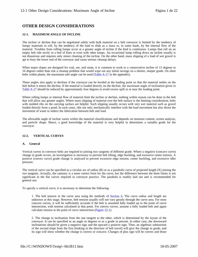
1. The belt tension in the curve area using the methods of Section 6. The curve radius and length are unknown at this stage. However, belt tension usually will not vary greatly through the curve area. For most concave curves, it will be sufficiently accurate if the belt is assumed fully loaded up to the point of curve intersection, with tension calculated at that point. For convex curves, assume a fully loaded belt and again calculate tension at the point of curve intersection (Figure 12-1).
2. The change in inclination from the one tangent to the other, which is determined by the layout of the conveyor. It can be specified as an angle in degrees or as a grade in percent. In either case, the downward inclinations should be given a negative sign and the upward a positive sign. Then, an algebraic subtraction of the second slope from the first (looking in the direction of belt travel) will give the change in grade, and its sign will show whether the change is convex or concave. Changes of plus sign will be convex and those
Página 1 de 2212-1 Other Design Considerations: Maximum Angle of Incline
18-05-2007file://C:\WINDOWS\Temp\~hh1B11.htm
of minus sign will be concave.
Figure 12-1 Assumed Vertical Curve Shape and Loading for Tension Calculations Only
12-2. MAXIMUM ANGLE OF INCLINE
B. Concave Vertical Curves
1. Concave Curve Radius or Length to Prevent Bell Lifting
This type of curve is the most common cause of curve trouble in that lack of a correct concave curve is immediately apparent in belt lifting. Convex curves can be improperly laid out and still permit belt operation at the expense of belt life due to high edge tension and/or idler junction creasing.
The most important part of calculating a concave curve is to determine belt tension--not simply operating tension but peak tension resulting from acceleration or braking or from any probable spasmodic loading combination. The belt is presumed to be empty in the region of the curve and loaded up to that point, which is the condition most apt to cause the belt to lift.
To compensate arbitrarily for increased tension due to acceleration or braking, the belt weight is used as one- half its actual value; thus, the curves for ordinary conveyors can be safely calculated from operating belt tension. When extreme cases of acceleration or braking are involved, or where room for curves is restricted, the actual peak accelerating tension should be calculated.
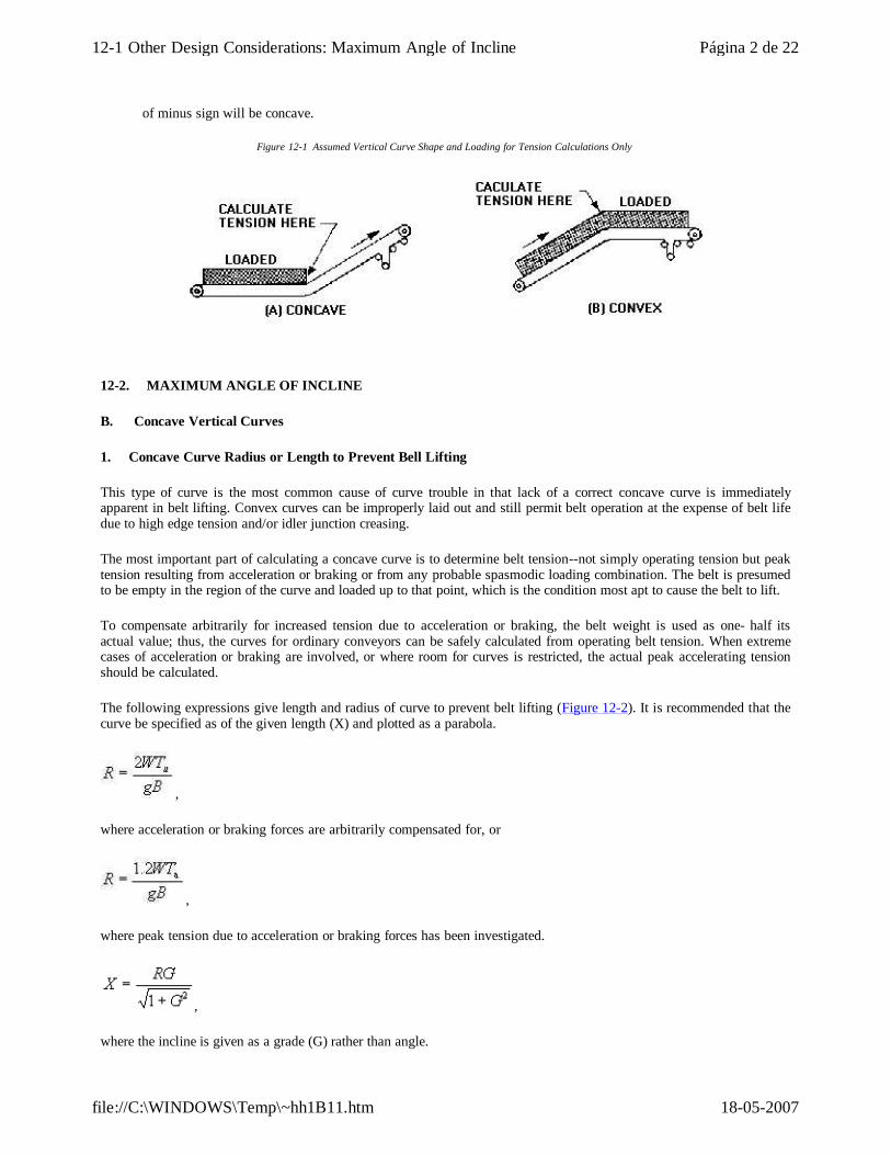
The following expressions give length and radius of curve to prevent belt lifting (Figure 12-2). It is recommended that the curve be specified as of the given length (X) and plotted as a parabola.
,
where acceleration or braking forces are arbitrarily compensated for, or
,
where peak tension due to acceleration or braking forces has been investigated.
,
where the incline is given as a grade (G) rather than angle.
Página 2 de 2212-1 Other Design Considerations: Maximum Angle of Incline
18-05-2007file://C:\WINDOWS\Temp\~hh1B11.htm
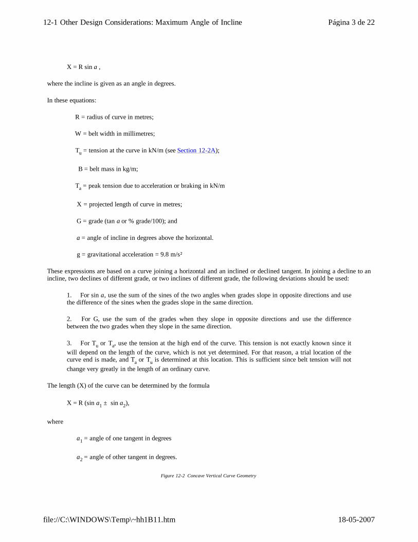
X = R sin a ,
where the incline is given as an angle in degrees.
In these equations:
R = radius of curve in metres;
W = belt width in millimetres;
Tu = tension at the curve in kN/m (see Section 12-2A);
B = belt mass in kg/m;
Ta = peak tension due to acceleration or braking in kN/m
X = projected length of curve in metres;
G = grade (tan a or % grade/100); and
a = angle of incline in degrees above the horizontal.
g = gravitational acceleration = 9.8 m/s²
These expressions are based on a curve joining a horizontal and an inclined or declined tangent. In joining a decline to an incline, two declines of different grade, or two inclines of different grade, the following deviations should be used:
1. For sin a, use the sum of the sines of the two angles when grades slope in opposite directions and use the difference of the sines when the grades slope in the same direction.
2. For G, use the sum of the grades when they slope in opposite directions and use the difference between the two grades when they slope in the same direction.
3. For Tu or Ta, use the tension at the high end of the curve. This tension is not exactly known since it will depend on the length of the curve, which is not yet determined. For that reason, a trial location of the curve end is made, and Ta or Tu is determined at this location. This is sufficient since belt tension will not change very greatly in the length of an ordinary curve.
The length (X) of the curve can be determined by the formula
X = R (sin a1 ± sin a2),
where
a1 = angle of one tangent in degrees
a2 = angle of other tangent in degrees.
Figure 12-2 Concave Vertical Curve Geometry
Página 3 de 2212-1 Other Design Considerations: Maximum Angle of Incline
18-05-2007file://C:\WINDOWS\Temp\~hh1B11.htm
12-2. VERTICAL CURVES
B. Concave Vertical Curves
2. Concave Curve Radius or Length to Control Edge Sagging and to Limit Center Tension
a. General
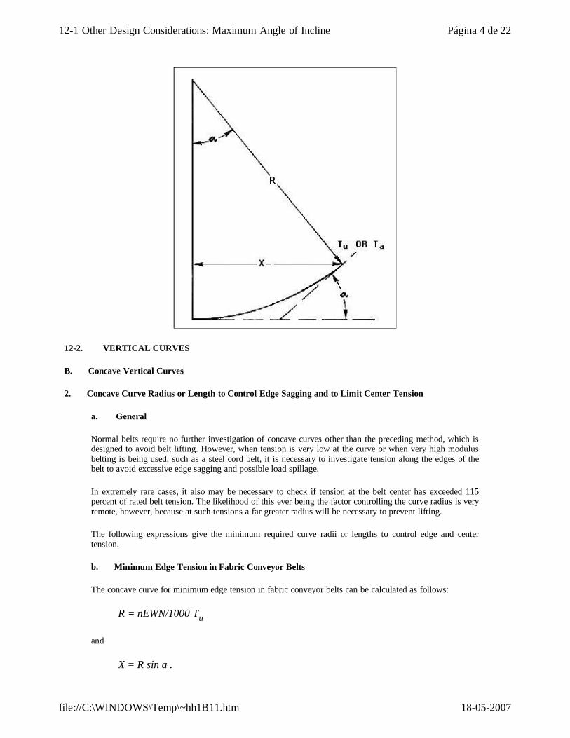
Normal belts require no further investigation of concave curves other than the preceding method, which is designed to avoid belt lifting. However, when tension is very low at the curve or when very high modulus belting is being used, such as a steel cord belt, it is necessary to investigate tension along the edges of the belt to avoid excessive edge sagging and possible load spillage.
In extremely rare cases, it also may be necessary to check if tension at the belt center has exceeded 115 percent of rated belt tension. The likelihood of this ever being the factor controlling the curve radius is very remote, however, because at such tensions a far greater radius will be necessary to prevent lifting.
The following expressions give the minimum required curve radii or lengths to control edge and center tension.
b. Minimum Edge Tension in Fabric Conveyor Belts
The concave curve for minimum edge tension in fabric conveyor belts can be calculated as follows:
R = nEWN/1000 Tu
and
X = R sin a .
Página 4 de 2212-1 Other Design Considerations: Maximum Angle of Incline
18-05-2007file://C:\WINDOWS\Temp\~hh1B11.htm

This equation will give a radius so that the edge tension will be zero, which is adequate in most cases. If some edge tension is desired, simply substitute the desired tension in the denominator. For example, to have 250 kN/m edge tension, the denominator would read 1000 (Tu - 250).
c. Minimum Edge Tension in Steel Cord Belts
The concave curve for minimum edge tension in steel cord belts can be calculated as follows:
R = WE sin φ /12 000Tu
and
X = R sin a .
d. 115 Percent Tr Maximum Center Tension in All Types of Belts
The concave curve for maximum center tension can be calculated as follows:
R = nEWN/2000 (1.15 Tr - Tu )
and
X = R sin a .
where in Items b, c, and d:
R = radius of curve in metres;
n = 0.222 sin φ
(20 deg, n = 0.076,
30 deg, n = 0.111,
35 deg, n = 0.127,
45 deg, n = 0.157);
E = elastic modulus in kN/ply/m (fabric belts) and kN/m width (steel cord belts); see appendix;
W = belt width in millimetres;
N = number of plies (N = 1 for steel cord belts);
Tu = tension at the curve in kN/m (see Section 12-2A);
X = projected length of curve in metres;
a = angle between the horizontal and the incline or decline tangents to the conveyor in degrees. When neither tangent is horizontal, a may be made up of two angles, a1 and a2. When sin a is used, it is written
Página 5 de 2212-1 Other Design Considerations: Maximum Angle of Incline
18-05-2007file://C:\WINDOWS\Temp\~hh1B11.htm
as sin a1 ± sin a2 (see Examples I, II, and III in Section 12-2B3 );
Tr = rated tension for specified belt in kN/m; and
φ = troughing idler angle.
12-2. VERTICAL CURVES
B. Concave Vertical Curves
3. Concave Curve Layout
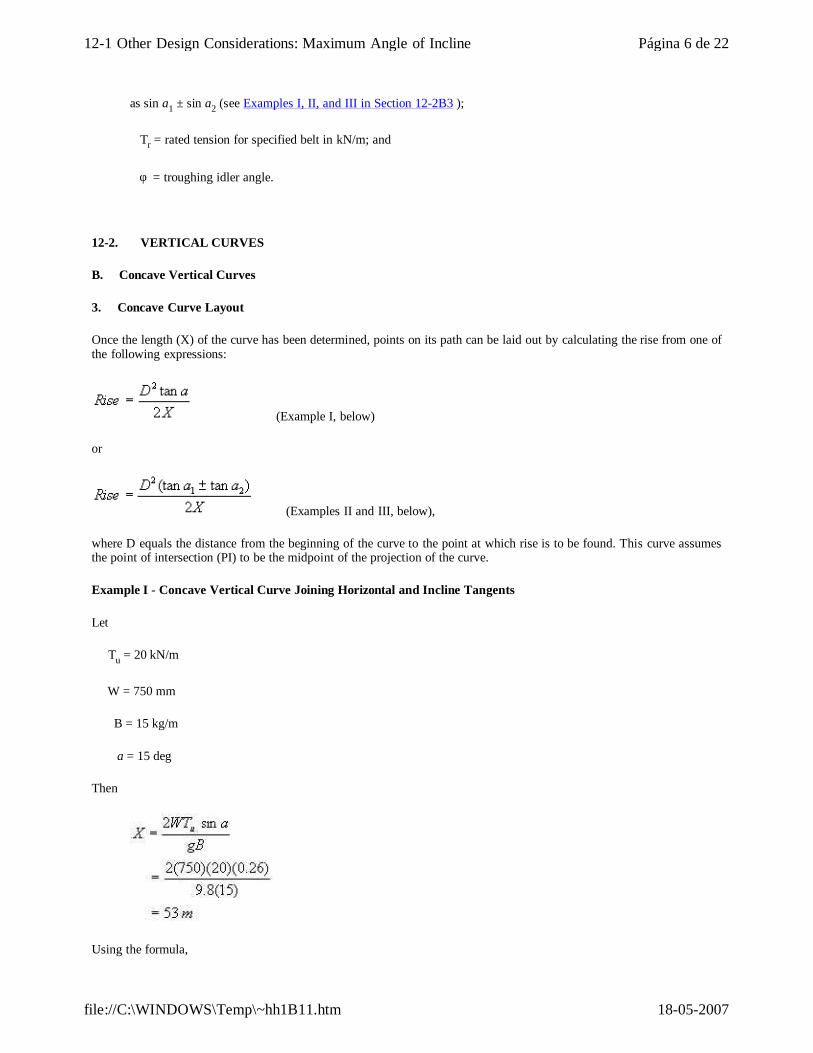
Once the length (X) of the curve has been determined, points on its path can be laid out by calculating the rise from one of the following expressions:
(Example I, below)
or
(Examples II and III, below),
where D equals the distance from the beginning of the curve to the point at which rise is to be found. This curve assumes the point of intersection (PI) to be the midpoint of the projection of the curve.
Example I - Concave Vertical Curve Joining Horizontal and Incline Tangents
Let
Tu = 20 kN/m
W = 750 mm
B = 15 kg/m
a = 15 deg
Then
Using the formula,
Página 6 de 2212-1 Other Design Considerations: Maximum Angle of Incline
18-05-2007file://C:\WINDOWS\Temp\~hh1B11.htm
,
the curve is laid out as in Figure 12-3.
Figure 12-3 Concave Vertical Curve Joining Horizontal and Incline Tangents
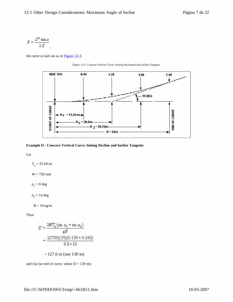
Example II - Concave Vertical Curve Joining Decline and Incline Tangents
Let
Tu = 35 kN/m
W = 750 mm
a1 = 8 deg
a2 = 14 deg
B = 16 kg/m
Then
= 127.6 m (use 130 m)
and rise (at end of curve, where D = 130 m):
Página 7 de 2212-1 Other Design Considerations: Maximum Angle of Incline
18-05-2007file://C:\WINDOWS\Temp\~hh1B11.htm
Rises at intermediate points determined by this formula also are shown in Figure 12-4.
Figure 12-4 Concave Vertical Curve Joining Decline and Incline Tangents
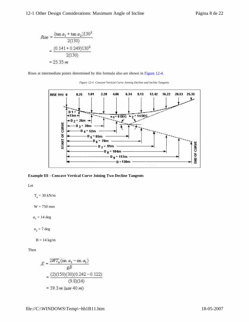
Example III - Concave Vertical Curve Joining Two Decline Tangents
Let
Tu = 30 kN/m
W = 750 mm
a1 = 14 deg
a2 = 7 deg
B = 14 kg/m
Then
Página 8 de 2212-1 Other Design Considerations: Maximum Angle of Incline
18-05-2007file://C:\WINDOWS\Temp\~hh1B11.htm
and rise (at end of curve, where D = 40 m)
Rises at intermediate points determined by this formula also are shown in Figure 12-5.
Figure 12-5 Concave Vertical Curve Joining Two Decline Tangents
12-2. VERTICAL CURVES
C. Convex Vertical Curves
1. General
Convex curves ordinarily can be shorter than concave curves because the problem of lifting off the idlers, which governs most concave curves, does not exist. Investigation of convex curves is from the standpoint of excess tension in the belt edges; from the standpoint of too little tension at the centerline of the belt, which might result in buckling; or from the standpoint of excess idler pressure resulting from the downward component of the belt tension.
2. Convex Curves to Limit Edge Tension in Belt
Belt edges have a greater tension than the center in a convex curve because they are elevated by the troughing idlers and consequently travel a longer path through the curve. To limit this edge tension to 15 percent above maximum rated tension for the belt, the radius of the curve must be
with terms as previously defined for concave curves (Section 12-2B).
Página 9 de 2212-1 Other Design Considerations: Maximum Angle of Incline
18-05-2007file://C:\WINDOWS\Temp\~hh1B11.htm
3. Convex Curves to Avoid Center Buckling or Idler Juncture Creasing of Belt
The center of the belt has less tension than the edges and can buckle if it becomes free of tension. To avoid such a conditions the radius of the curve should be
with terms as previously defined for concave curves. If a minimum center tension other than 0.05Tr is desired, simply substitute the new value in the above equation. For Tu, the same value as in the convex edge tension formula usually is used. Since a lower Tu demands a greater radius with the buckling formula, such values are sometimes used when created by a frequently encountered partial load condition. The Tu of an empty belt is rarely used since some empty buckling is not apt to be detrimental.
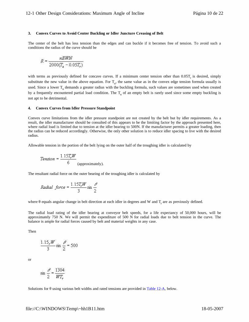
4. Convex Curves from Idler Pressure Standpoint
Convex curve limitations from the idler pressure standpoint are not created by the belt but by idler requirements. As a result, the idler manufacturer should be consulted of this appears to be the limiting factor by the approach presented here, where radial load is limited due to tension at the idler bearing to 500N. If the manufacturer permits a greater loading, then the radius can be reduced accordingly. Otherwise, the only other solution is to reduce idler spacing to live with the desired radius.
Allowable tension in the portion of the belt lying on the outer half of the troughing idler is calculated by
(approximately).
The resultant radial force on the outer bearing of the troughing idler is calculated by
where θ equals angular change in belt direction at each idler in degrees and W and Tr are as previously defined.
The radial load rating of the idler bearing at conveyor belt speeds, for a life expectancy of 50,000 hours, will be approximately 750 N. We will permit the expenditure of 500 N for radial loads due to belt tension in the curve. The balance is ample for radial forces caused by belt and material weights in any case.
Then
or
Solutions for θ using various belt widths and rated tensions are provided in Table 12-A, below.
Página 10 de 2212-1 Other Design Considerations: Maximum Angle of Incline
18-05-2007file://C:\WINDOWS\Temp\~hh1B11.htm
With a given change in conveyor grade, the total change divided by the allowable change per idler gives the number of idlers required in the curve. Then the length (X) of the curve is simply
,
where = idler spacing in meters, or
.
Values of θ (allowable change per idler) in Table 12-A, below, make no distinction between types of idlers but are conservative enough to cover all antifriction bearing idlers.
Where X (projected length of curve) is used rather than radius, X = R sin a, where a is total change in incline in degrees. Sin a becomes sin a1 ± sin a2 when both tangents to the curve have a slope.
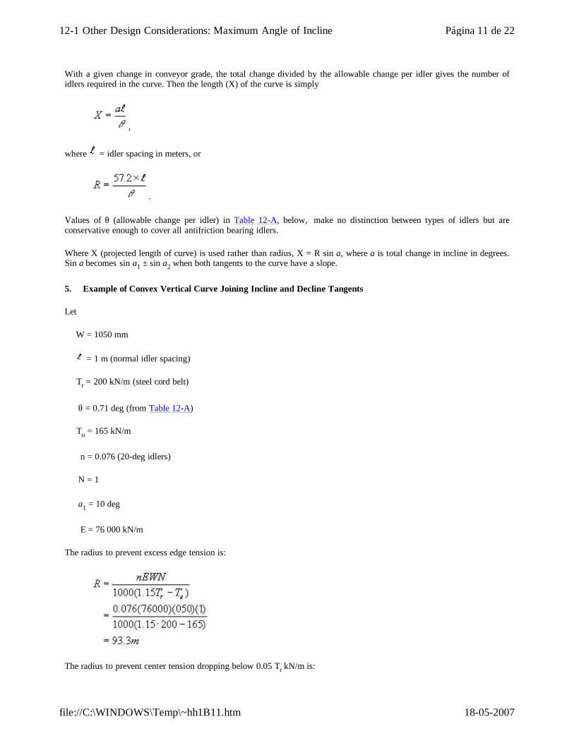
5. Example of Convex Vertical Curve Joining Incline and Decline Tangents
Let
W = 1050 mm
= 1 m (normal idler spacing)
Tr = 200 kN/m (steel cord belt)
θ = 0.71 deg (from Table 12-A)
Tu = 165 kN/m
n = 0.076 (20-deg idlers)
N = 1
a1 = 10 deg
E = 76 000 kN/m
The radius to prevent excess edge tension is:
The radius to prevent center tension dropping below 0.05 Tr kN/m is:
Página 11 de 2212-1 Other Design Considerations: Maximum Angle of Incline
18-05-2007file://C:\WINDOWS\Temp\~hh1B11.htm
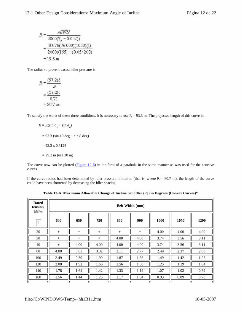
The radius to prevent excess idler pressure is:
To satisfy the worst of these three conditions, it is necessary to use R = 93.3 m. The projected length of this curve is:
X = R(sin a1 + sin a2)
= 93.3 (sin 10 deg + sin 8 deg)
= 93.3 x 0.3128
= 29.2 m (use 30 m)
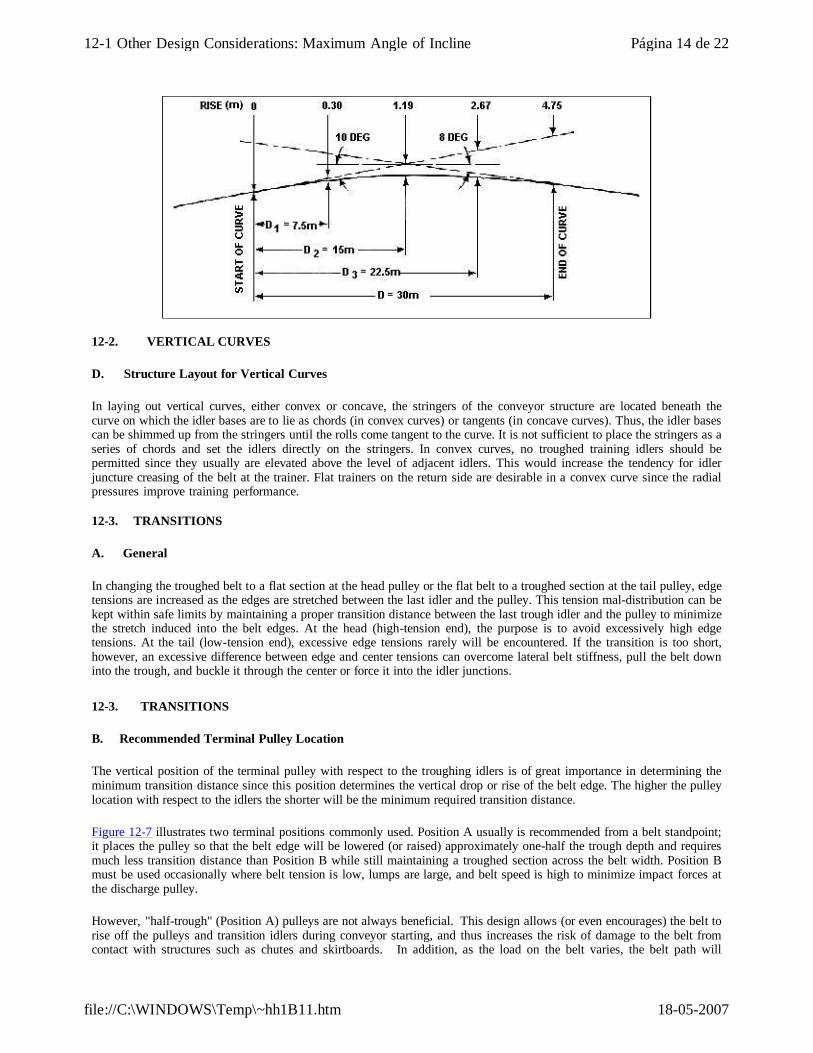
The curve now can be plotted (Figure 12-6) in the form of a parabola in the same manner as was used for the concave curves.
If the curve radius had been determined by idler pressure limitation (that is, where R = 80.7 m), the length of the curve could have been shortened by decreasing the idler spacing.
Table 12-A Maximum Allowable Change of Incline per Idler ( θ ) in Degrees (Convex Curves)*
Rated tension, kN/m
Belt Width (mm)
600 650 750 800 900 1000 1050 1200
20 + + + + + 4.00 4.00 4.00
30 + + + 4.00 4.00 3.74 3.56 3.11
40 + 4.00 4.00 4.00 4.00 3.74 3.56 3.11
60 4.00 3.83 3.32 3.11 2.77 2.49 2.37 2.08
100 2.49 2.30 1.99 1.87 1.66 1.49 1.42 1.25
120 2.08 1.92 1.66 1.56 1.38 1.25 1.19 1.04
140 1.78 1.64 1.42 1.33 1.19 1.07 1.02 0.89
160 1.56 1.44 1.25 1.17 1.04 0.93 0.89 0.78
Página 12 de 2212-1 Other Design Considerations: Maximum Angle of Incline
18-05-2007file://C:\WINDOWS\Temp\~hh1B11.htm

*Based on 500-N idler pressure limitation; any type or angle of idler. +4.00 degree maximum.
Figure 12-6 Convex Vertical Curve Joining Incline and Decline Tangents
180 1.38 1.28 1.11 1.04 0.92 0.83 0.79 0.69
200 1.25 1.15 1.00 0.93 0.83 0.75 0.71 0.62
250 1.00 0.92 0.80 0.75 0.66 0.60 0.57 0.50
300 0.83 0.77 0.66 0.62 0.55 0.50 0.47 0.50
400 0.62 0.57 0.50 0.47 0.42 0.37 0.36 0.31
500 0.50 0.46 0.40 0.37 0.33 0.30 0.28 0.25
Maximum Allowable Change of Incline per Idler (θ) in Degrees (Convex Curves)* (continued from above)
Rated tension, kN/m
Belt width (mm)
1350 1400 1500 1600 1800
20 4.00 4.00 4.00 4.00 4.0030 3.69 3.56 3.32 3.11 2.76 40 2.77 2.67 2.49 2.33 2.0860 1.84 1.78 1.66 1.56 1.38 80 1.38 1.33 1.25 1.17 1.04
100 1.11 1.07 1.00 0.93 0.83120 0.92 0.89 0.83 0.78 0.69140 0.79 0.76 0.71 0.67 0.59160 0.69 0.67 0.62 0.58 0.52180 0.61 0.59 0.55 0.52 0.46200 0.55 0.53 0.50 0.47 0.42250 0.44 0.43 0.40 0.37 0.33300 0.37 0.36 0.33 0.31 0.28400 0.28 0.27 0.25 0.23 0.21500 0.22 0.21 0.20 0.19 0.17
Página 13 de 2212-1 Other Design Considerations: Maximum Angle of Incline
18-05-2007file://C:\WINDOWS\Temp\~hh1B11.htm
12-2. VERTICAL CURVES
D. Structure Layout for Vertical Curves
In laying out vertical curves, either convex or concave, the stringers of the conveyor structure are located beneath the curve on which the idler bases are to lie as chords (in convex curves) or tangents (in concave curves). Thus, the idler bases can be shimmed up from the stringers until the rolls come tangent to the curve. It is not sufficient to place the stringers as a series of chords and set the idlers directly on the stringers. In convex curves, no troughed training idlers should be permitted since they usually are elevated above the level of adjacent idlers. This would increase the tendency for idler juncture creasing of the belt at the trainer. Flat trainers on the return side are desirable in a convex curve since the radial pressures improve training performance.
12-3. TRANSITIONS
A. General
In changing the troughed belt to a flat section at the head pulley or the flat belt to a troughed section at the tail pulley, edge tensions are increased as the edges are stretched between the last idler and the pulley. This tension mal-distribution can be kept within safe limits by maintaining a proper transition distance between the last trough idler and the pulley to minimize the stretch induced into the belt edges. At the head (high-tension end), the purpose is to avoid excessively high edge tensions. At the tail (low-tension end), excessive edge tensions rarely will be encountered. If the transition is too short, however, an excessive difference between edge and center tensions can overcome lateral belt stiffness, pull the belt down into the trough, and buckle it through the center or force it into the idler junctions.
12-3. TRANSITIONS
B. Recommended Terminal Pulley Location
The vertical position of the terminal pulley with respect to the troughing idlers is of great importance in determining the minimum transition distance since this position determines the vertical drop or rise of the belt edge. The higher the pulley location with respect to the idlers the shorter will be the minimum required transition distance.
Figure 12-7 illustrates two terminal positions commonly used. Position A usually is recommended from a belt standpoint; it places the pulley so that the belt edge will be lowered (or raised) approximately one-half the trough depth and requires much less transition distance than Position B while still maintaining a troughed section across the belt width. Position B must be used occasionally where belt tension is low, lumps are large, and belt speed is high to minimize impact forces at the discharge pulley.
However, "half-trough" (Position A) pulleys are not always beneficial. This design allows (or even encourages) the belt to rise off the pulleys and transition idlers during conveyor starting, and thus increases the risk of damage to the belt from contact with structures such as chutes and skirtboards. In addition, as the load on the belt varies, the belt path will
Página 14 de 2212-1 Other Design Considerations: Maximum Angle of Incline
18-05-2007file://C:\WINDOWS\Temp\~hh1B11.htm
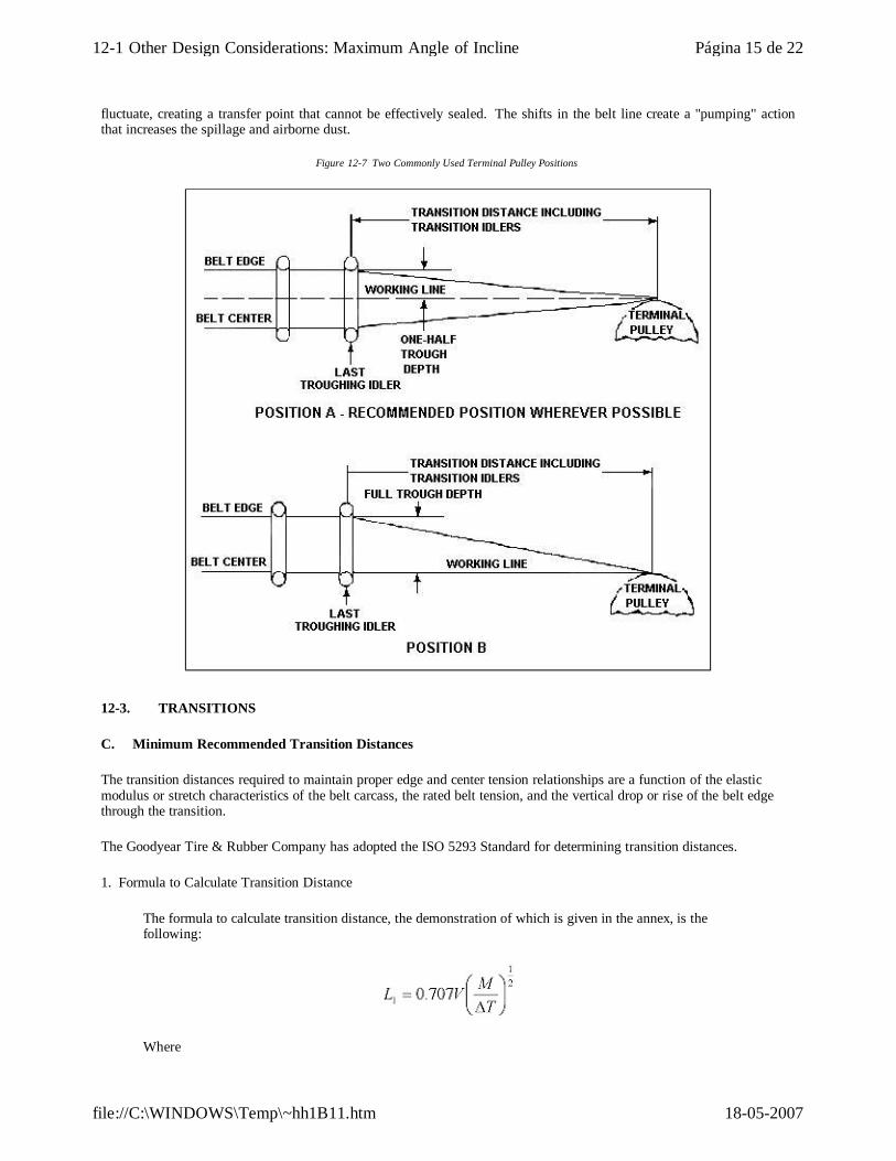
fluctuate, creating a transfer point that cannot be effectively sealed. The shifts in the belt line create a "pumping" action that increases the spillage and airborne dust.
Figure 12-7 Two Commonly Used Terminal Pulley Positions
12-3. TRANSITIONS
C. Minimum Recommended Transition Distances
The transition distances required to maintain proper edge and center tension relationships are a function of the elastic modulus or stretch characteristics of the belt carcass, the rated belt tension, and the vertical drop or rise of the belt edge through the transition.
The Goodyear Tire & Rubber Company has adopted the ISO 5293 Standard for determining transition distances.
1. Formula to Calculate Transition Distance
The formula to calculate transition distance, the demonstration of which is given in the annex, is the following:
Where
Página 15 de 2212-1 Other Design Considerations: Maximum Angle of Incline
18-05-2007file://C:\WINDOWS\Temp\~hh1B11.htm
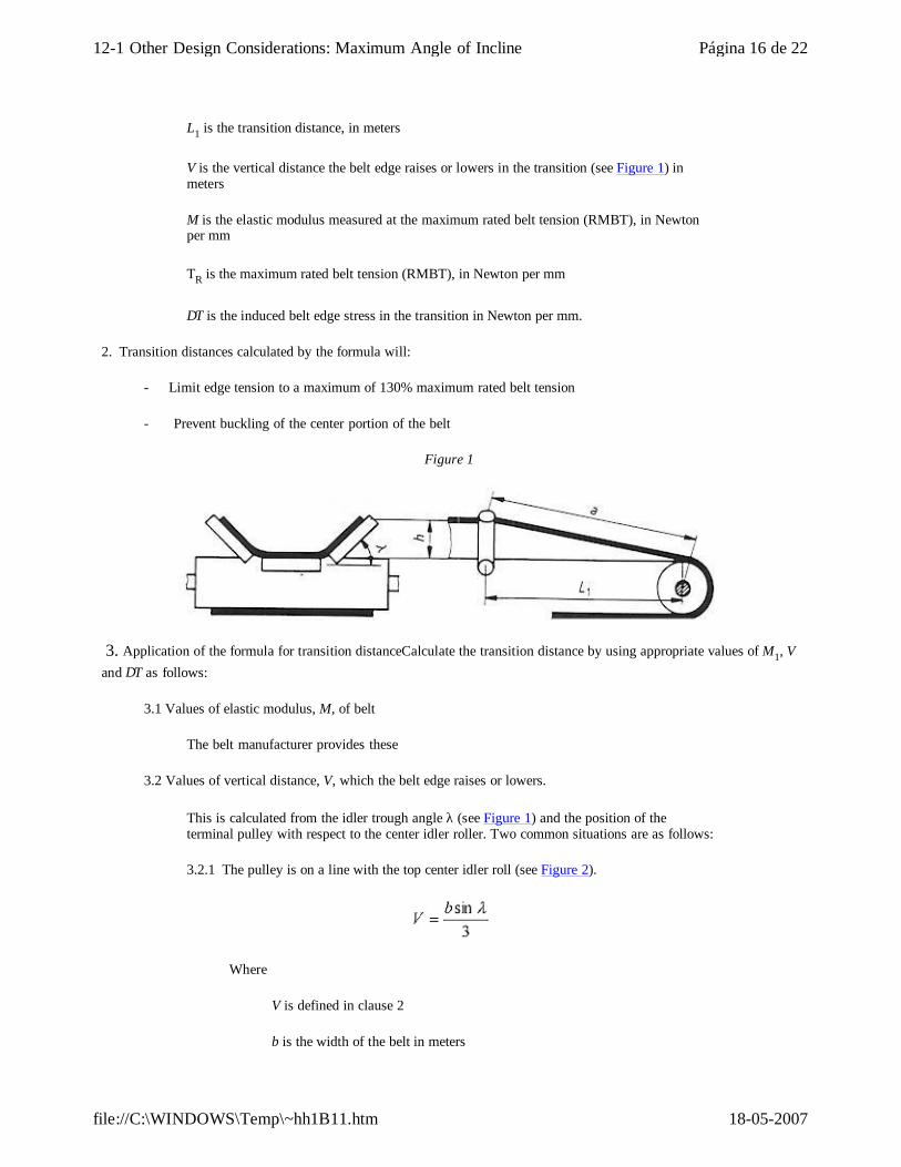
L1 is the transition distance, in meters
V is the vertical distance the belt edge raises or lowers in the transition (see Figure 1) in meters
M is the elastic modulus measured at the maximum rated belt tension (RMBT), in Newton per mm
TR is the maximum rated belt tension (RMBT), in Newton per mm
∆T is the induced belt edge stress in the transition in Newton per mm.
2. Transition distances calculated by the formula will:
- Limit edge tension to a maximum of 130% maximum rated belt tension
- Prevent buckling of the center portion of the belt
Figure 1
3. Application of the formula for transition distanceCalculate the transition distance by using appropriate values of M1, V and ∆T as follows:
3.1 Values of elastic modulus, M, of belt
The belt manufacturer provides these
3.2 Values of vertical distance, V, which the belt edge raises or lowers.
This is calculated from the idler trough angle λ (see Figure 1) and the position of the terminal pulley with respect to the center idler roller. Two common situations are as follows:
3.2.1 The pulley is on a line with the top center idler roll (see Figure 2).
Where
V is defined in clause 2
b is the width of the belt in meters
Página 16 de 2212-1 Other Design Considerations: Maximum Angle of Incline
18-05-2007file://C:\WINDOWS\Temp\~hh1B11.htm
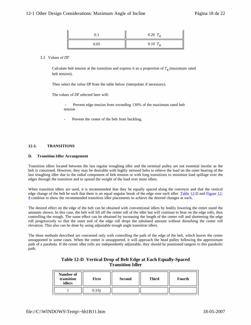
λ is the idler trough angle
Figure 2
3.2.2 The pulley is elevated by 1/3 of the trough depth above the line of the center idler roller. (see Figure 3).
V is then equal to 2/3 full trough depth, then
where V, b and λ are defined in 3.2.1
Figure 3
Ratio of Belt Tension at Transition to TR ∆T
1.0 0.30 TR
0.9 0.35 TR
0.8 0.45 TR
0.7 0.55 TR
0.6 to 0.3 0.60 TR
0.2 0.40 TR
Página 17 de 2212-1 Other Design Considerations: Maximum Angle of Incline
18-05-2007file://C:\WINDOWS\Temp\~hh1B11.htm
3.3 Values of ∆T
Calculate belt tension at the transition and express it as a proportion of TR (maximum rated belt tension).
Then select the value ∆T from the table below (interpolate if necessary).
The values of ∆T selected here will:
- Prevent edge tension from exceeding 130% of the maximum rated belt tension
- Prevent the center of the belt from buckling.
0.1 0.20 TR
0.05 0.10 TR
12-3. TRANSITIONS
D. Transition Idler Arrangement
Transition idlers located between the last regular troughing idler and the terminal pulley are not essential insofar as the belt is concerned. However, they may be desirable with highly stressed belts to relieve the load on the outer bearing of the last troughing idler due to the radial component of belt tension or with long transitions to minimize load spillage over the edges through the transition and to spread the weight of the load over more idlers.
When transition idlers are used, it is recommended that they be equally spaced along the conveyor and that the vertical edge change of the belt be such that there is an equal angular break of the edge over each idler. Table 12-D and Figure 12-8 combine to show the recommended transition idler placements to achieve the desired changes at each.
The desired effect on the edge of the belt can be obtained with conventional idlers by bodily lowering the entire stand the amounts shown. In this case, the belt will lift off the center roll of the idler but will continue to bear on the edge rolls, thus controlling the trough. The same effect can be obtained by increasing the length of the center roll and shortening the edge roll progressively so that the outer end of the edge roll drops the tabulated amount without disturbing the center roll elevation. This also can be done by using adjustable trough angle transition idlers.
The three methods described are concerned only with controlling the path of the edge of the belt, which leaves the center unsupported in some cases. When the center is unsupported, it will approach the head pulley following the approximate path of a parabola. If the center idler rolls are independently adjustable, they should be positioned tangent to this parabolic path.
Table 12-D Vertical Drop of Belt Edge at Each Equally-Spaced Transition Idler
Number of transition
idlersFirst Second Third Fourth
1 0.33y
Página 18 de 2212-1 Other Design Considerations: Maximum Angle of Incline
18-05-2007file://C:\WINDOWS\Temp\~hh1B11.htm
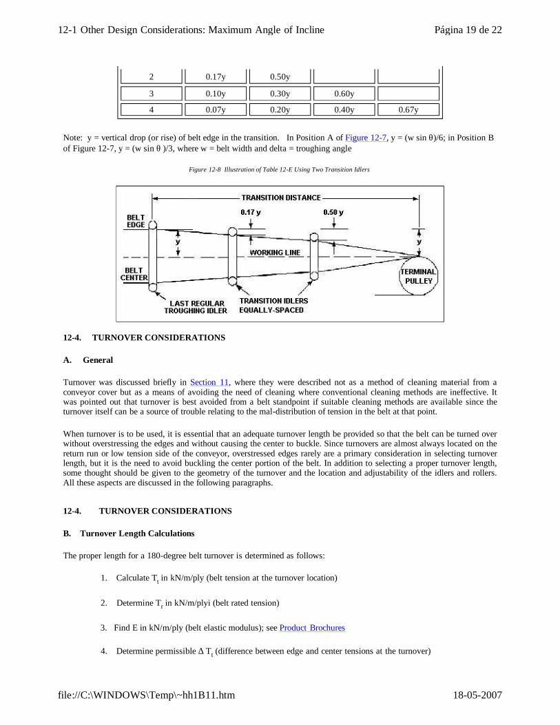
Note: y = vertical drop (or rise) of belt edge in the transition. In Position A of Figure 12-7, y = (w sin θ)/6; in Position B of Figure 12-7, y = (w sin θ )/3, where w = belt width and delta = troughing angle
Figure 12-8 Illustration of Table 12-E Using Two Transition Idlers
2 0.17y 0.50y 3 0.10y 0.30y 0.60y 4 0.07y 0.20y 0.40y 0.67y
12-4. TURNOVER CONSIDERATIONS
A. General
Turnover was discussed briefly in Section 11, where they were described not as a method of cleaning material from a conveyor cover but as a means of avoiding the need of cleaning where conventional cleaning methods are ineffective. It was pointed out that turnover is best avoided from a belt standpoint if suitable cleaning methods are available since the turnover itself can be a source of trouble relating to the mal-distribution of tension in the belt at that point.
When turnover is to be used, it is essential that an adequate turnover length be provided so that the belt can be turned over without overstressing the edges and without causing the center to buckle. Since turnovers are almost always located on the return run or low tension side of the conveyor, overstressed edges rarely are a primary consideration in selecting turnover length, but it is the need to avoid buckling the center portion of the belt. In addition to selecting a proper turnover length, some thought should be given to the geometry of the turnover and the location and adjustability of the idlers and rollers. All these aspects are discussed in the following paragraphs.
12-4. TURNOVER CONSIDERATIONS
B. Turnover Length Calculations
The proper length for a 180-degree belt turnover is determined as follows:
1. Calculate Tt in kN/m/ply (belt tension at the turnover location)
2. Determine Tr in kN/m/plyi (belt rated tension)
3. Find E in kN/m/ply (belt elastic modulus); see Product Brochures
4. Determine permissible ∆ Tt (difference between edge and center tensions at the turnover)
Página 19 de 2212-1 Other Design Considerations: Maximum Angle of Incline
18-05-2007file://C:\WINDOWS\Temp\~hh1B11.htm
a. ∆ Tt = 1.8Tt (when Tt ≤ 0.5Tr).
b. ∆ Tt = 1.8(Tr-Tt) (where Tt > 0.5Tr).
NOTE:
∆ Tt is almost always that of Condition (a) since most turnovers are in low-tension areas.
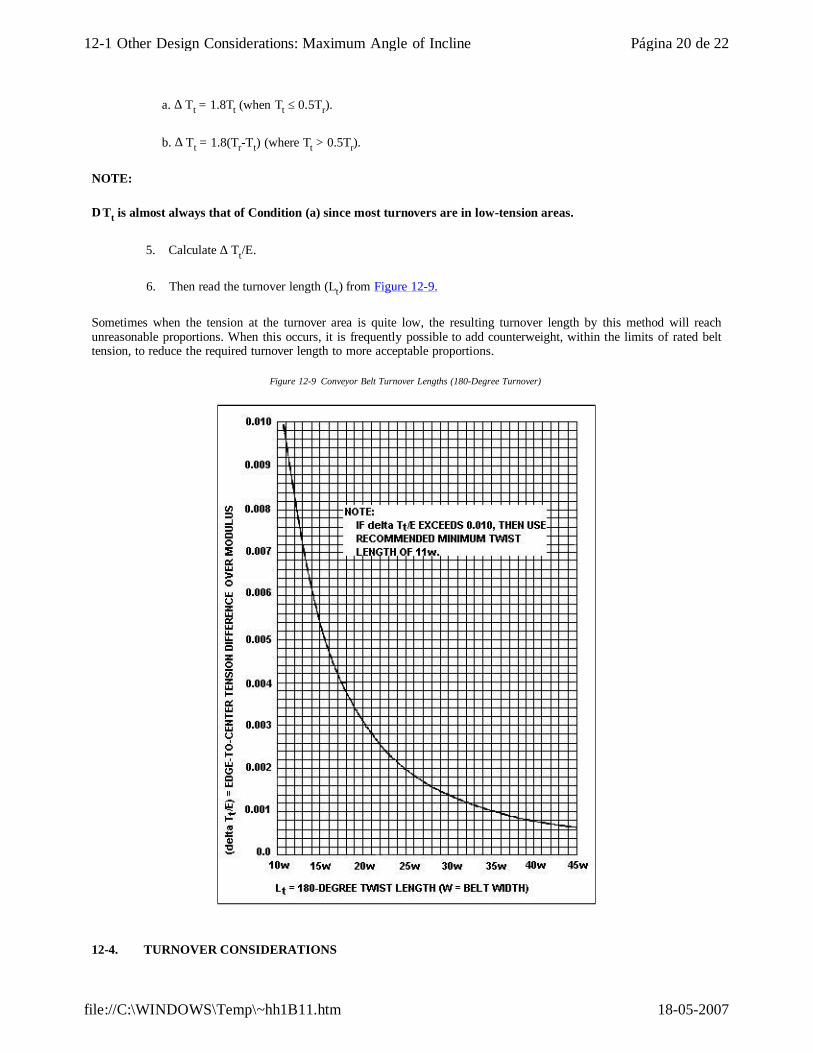
5. Calculate ∆ Tt/E.
6. Then read the turnover length (Lt) from Figure 12-9.
Sometimes when the tension at the turnover area is quite low, the resulting turnover length by this method will reach unreasonable proportions. When this occurs, it is frequently possible to add counterweight, within the limits of rated belt tension, to reduce the required turnover length to more acceptable proportions.
Figure 12-9 Conveyor Belt Turnover Lengths (180-Degree Turnover)
12-4. TURNOVER CONSIDERATIONS
Página 20 de 2212-1 Other Design Considerations: Maximum Angle of Incline
18-05-2007file://C:\WINDOWS\Temp\~hh1B11.htm
C. Belt Sag in Turnover Area
In turnovers that have a horizontal component, it is sometimes desirable to estimate the amount the belt will sag. This can be done as follows:
where
B = belt mass (in kilgrams per metre),
Lth = horizontal component of turnover length,
Ttt = total belt tension at the turnover in newtons.
g = gravitational accelerations = 9.8 m/s²
This formula gives the sag that would occur if the belt were not turned over. Actual sag will be 60 to 70 percent of this value because of belt stiffness and a column effect at the center of the turnover where the belt is vertical.
12-4. TURNOVER CONSIDERATIONS
D. General Turnover Comments and Recommendations
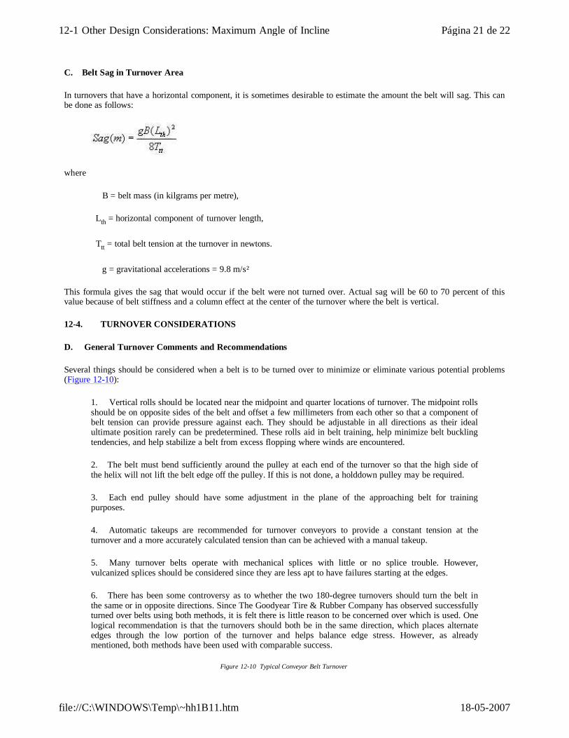
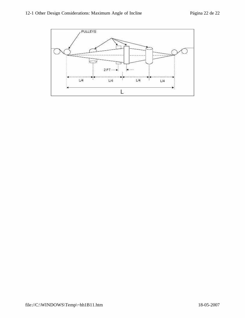
Several things should be considered when a belt is to be turned over to minimize or eliminate various potential problems (Figure 12-10):
1. Vertical rolls should be located near the midpoint and quarter locations of turnover. The midpoint rolls should be on opposite sides of the belt and offset a few millimeters from each other so that a component of belt tension can provide pressure against each. They should be adjustable in all directions as their ideal ultimate position rarely can be predetermined. These rolls aid in belt training, help minimize belt buckling tendencies, and help stabilize a belt from excess flopping where winds are encountered.
2. The belt must bend sufficiently around the pulley at each end of the turnover so that the high side of the helix will not lift the belt edge off the pulley. If this is not done, a holddown pulley may be required.
3. Each end pulley should have some adjustment in the plane of the approaching belt for training purposes.
4. Automatic takeups are recommended for turnover conveyors to provide a constant tension at the turnover and a more accurately calculated tension than can be achieved with a manual takeup.
5. Many turnover belts operate with mechanical splices with little or no splice trouble. However, vulcanized splices should be considered since they are less apt to have failures starting at the edges.
6. There has been some controversy as to whether the two 180-degree turnovers should turn the belt in the same or in opposite directions. Since The Goodyear Tire & Rubber Company has observed successfully turned over belts using both methods, it is felt there is little reason to be concerned over which is used. One logical recommendation is that the turnovers should both be in the same direction, which places alternate edges through the low portion of the turnover and helps balance edge stress. However, as already mentioned, both methods have been used with comparable success.
Figure 12-10 Typical Conveyor Belt Turnover
Página 21 de 2212-1 Other Design Considerations: Maximum Angle of Incline
18-05-2007file://C:\WINDOWS\Temp\~hh1B11.htm
Página 22 de 2212-1 Other Design Considerations: Maximum Angle of Incline
18-05-2007file://C:\WINDOWS\Temp\~hh1B11.htm
5-9. WEIGHTS OF MATERIALS
The mass per cubic metre of many materials is subject to considerable variation. The size of material, whether it is wet or dry, and--in the case of minerals--the natural formations account for this variation. Hence, whenever possible, the density for the size and kind of material involved should be accurately determined.
Solid or compact weights, which are available for most materials, cannot be used in the determination of the capacity of belt conveyors and elevators that handle broken or loose materials.
The densities given in Table A-17 in the appendix are based on the normal condition of the material. Table A-17 also includes recommended maximum inclines and preferred cover compounds.
Página 1 de 15-9 Weights of Materials
18-05-2007mk:@MSITStore:G:\HANDBO~1\MGDYRH~1.CHM::/Section%205/5-9.htm
SAFETY DEVICES
14-1. GENERAL
Historically, belt conveyor systems have provided one of the most accident-free methods of transporting bulk materials. However, even that record can be improved. In safety, two things come to mind: (1) safety for operating personnel and others near the conveyor and (2) devices that protect the belt and equipment.
Some devices protect both people and belts (for example, pull wires along the conveyor). With proper precautions, belt conveyors can be operated safely. However, as with any moving machinery, they must be treated with respect and with the knowledge that they can cause injuries. Once that fact is recognized, safety is ensured as long as it is practiced.
14-2. PERSONNEL PROTECTION DEVICES
A. Emergency Stop Switches
Emergency stop switches should be placed where possible danger exists. These switch locations usually would be actuated by trip wires. In addition to drive, takeup, and tail areas, it is customary to install pull wires alongside long center conveyors. Switches are spaced at 100 m to 200-m intervals, which represent about the greatest distance at which a switch can reasonably be actuated. In case of shutdown, lights located at the open switch facilitate location of the open circuit; this represents more of a convenience than a necessity.
14-2. PERSONNEL PROTECTION DEVICES
B. Warning Horns
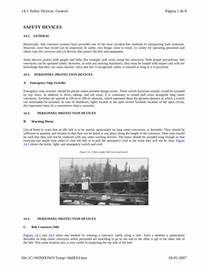
Use of horns to warn that an idle belt is to be started, particularly on long center conveyors, is desirable. They should be sufficient in quantity and located so that they can be heard at any place along the length of the conveyor. Their tone should be such that they will not be confused with any other warning devices. The horns should be sounded long enough so that everyone has ample time either to clear the belt or to pull the emergency cord in the event they will not be clear. Figure 14-1 shows the horns, light, and emergency switch and cord.
Figure 14-1 Horn, Light, Pull Cord, and Switch
14-2. PERSONNEL PROTECTION DEVICES
C. Belt Crossover Stile
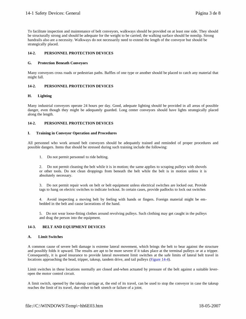
Figures 14-2 and 14-3 show one method of crossing a conveyor safely using a stile. Such a method is particularly desirable on long center conveyors where personnel are unwilling to go to one end or the other to get to the other side of the belt. This same location also is very useful in inspecting the top side of the belt.
Página 1 de 814-1 Safety Devices: General
18-05-2007file://C:\WINDOWS\Temp\~hh6E03.htm
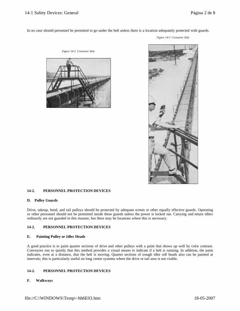
In no case should personnel be permitted to go under the belt unless there is a location adequately protected with guards.
Figure 14-2 Crossover Stile
Figure 14-3 Crossover Stile
14-2. PERSONNEL PROTECTION DEVICES
D. Pulley Guards
Drive, takeup, bend, and tail pulleys should be protected by adequate screen or other equally effective guards. Operating or other personnel should not be permitted inside these guards unless the power is locked out. Carrying and return idlers ordinarily are not guarded in this manner, but there may be locations where this is necessary.
14-2. PERSONNEL PROTECTION DEVICES
E. Painting Pulley or Idler Heads
A good practice is to paint quarter sections of drive and other pulleys with a paint that shows up well by color contrast. Conveyors run so quietly that this method provides a visual means to indicate if a belt is running. In addition, the paint indicates, even at a distance, that the belt is moving. Quarter sections of trough idler roll heads also can be painted at intervals; this is particularly useful on long center systems where the drive or tail area is not visible.
14-2. PERSONNEL PROTECTION DEVICES
F. Walkways
Página 2 de 814-1 Safety Devices: General
18-05-2007file://C:\WINDOWS\Temp\~hh6E03.htm
To facilitate inspection and maintenance of belt conveyors, walkways should be provided on at least one side. They should be structurally strong and should be adequate for the weight to be carried; the walking surface should be nonslip. Strong handrails also are a necessity. Walkways do not necessarily need to extend the length of the conveyor but should be strategically placed.
14-2. PERSONNEL PROTECTION DEVICES
G. Protection Beneath Conveyors
Many conveyors cross roads or pedestrian paths. Baffles of one type or another should be placed to catch any material that might fall.
14-2. PERSONNEL PROTECTION DEVICES
H. Lighting
Many industrial conveyors operate 24 hours per day. Good, adequate lighting should be provided in all areas of possible danger, even though they might be adequately guarded. Long center conveyors should have lights strategically placed along the length.
14-2. PERSONNEL PROTECTION DEVICES
I. Training in Conveyor Operation and Procedures
All personnel who work around belt conveyors should be adequately trained and reminded of proper procedures and possible dangers. Items that should be stressed during such training include the following:
1. Do not permit personnel to ride belting.
2. Do not permit cleaning the belt while it is in motion; the same applies to scraping pulleys with shovels or other tools. Do not clean droppings from beneath the belt while the belt is in motion unless it is absolutely necessary.
3. Do not permit repair work on belt or belt equipment unless electrical switches are locked out. Provide tags to hang on electric switches to indicate lockout. In certain cases, provide padlocks to lock out switches
4. Avoid inspecting a moving belt by feeling with hands or fingers. Foreign material might be em- bedded in the belt and cause lacerations of the hand.
5. Do not wear loose-fitting clothes around revolving pulleys. Such clothing may get caught in the pulleys and drag the person into the equipment.
14-3. BELT AND EQUIPMENT DEVICES
A. Limit Switches
A common cause of severe belt damage is extreme lateral movement, which brings the belt to bear against the structure and possibly folds it upward. The results are apt to be more severe if it takes place at the terminal pulleys or at a tripper. Consequently, it is good insurance to provide lateral movement limit switches at the safe limits of lateral belt travel in locations approaching the head, tripper, takeup, tandem drive, and tail pulleys (Figure 14-4).
Limit switches in these locations normally are closed and-when actuated by pressure of the belt against a suitable lever-open the motor control circuit.
A limit switch, opened by the takeup carriage at, the end of its travel, can be used to stop the conveyor in case the takeup reaches the limit of its travel, due either to belt stretch or failure of a joint.
Página 3 de 814-1 Safety Devices: General
18-05-2007file://C:\WINDOWS\Temp\~hh6E03.htm
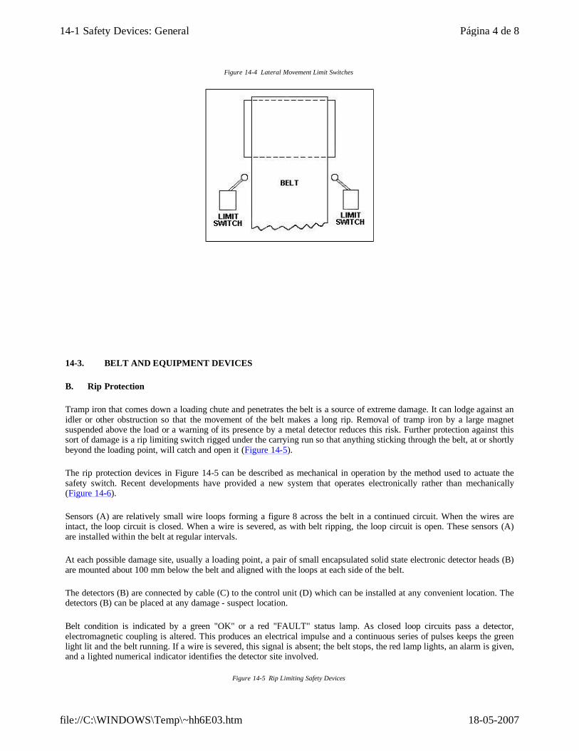
Figure 14-4 Lateral Movement Limit Switches
14-3. BELT AND EQUIPMENT DEVICES
B. Rip Protection
Tramp iron that comes down a loading chute and penetrates the belt is a source of extreme damage. It can lodge against an idler or other obstruction so that the movement of the belt makes a long rip. Removal of tramp iron by a large magnet suspended above the load or a warning of its presence by a metal detector reduces this risk. Further protection against this sort of damage is a rip limiting switch rigged under the carrying run so that anything sticking through the belt, at or shortly beyond the loading point, will catch and open it (Figure 14-5).
The rip protection devices in Figure 14-5 can be described as mechanical in operation by the method used to actuate the safety switch. Recent developments have provided a new system that operates electronically rather than mechanically (Figure 14-6).
Sensors (A) are relatively small wire loops forming a figure 8 across the belt in a continued circuit. When the wires are intact, the loop circuit is closed. When a wire is severed, as with belt ripping, the loop circuit is open. These sensors (A) are installed within the belt at regular intervals.
At each possible damage site, usually a loading point, a pair of small encapsulated solid state electronic detector heads (B) are mounted about 100 mm below the belt and aligned with the loops at each side of the belt.
The detectors (B) are connected by cable (C) to the control unit (D) which can be installed at any convenient location. The detectors (B) can be placed at any damage - suspect location.
Belt condition is indicated by a green "OK" or a red "FAULT" status lamp. As closed loop circuits pass a detector, electromagnetic coupling is altered. This produces an electrical impulse and a continuous series of pulses keeps the green light lit and the belt running. If a wire is severed, this signal is absent; the belt stops, the red lamp lights, an alarm is given, and a lighted numerical indicator identifies the detector site involved.
Figure 14-5 Rip Limiting Safety Devices
Página 4 de 814-1 Safety Devices: General
18-05-2007file://C:\WINDOWS\Temp\~hh6E03.htm
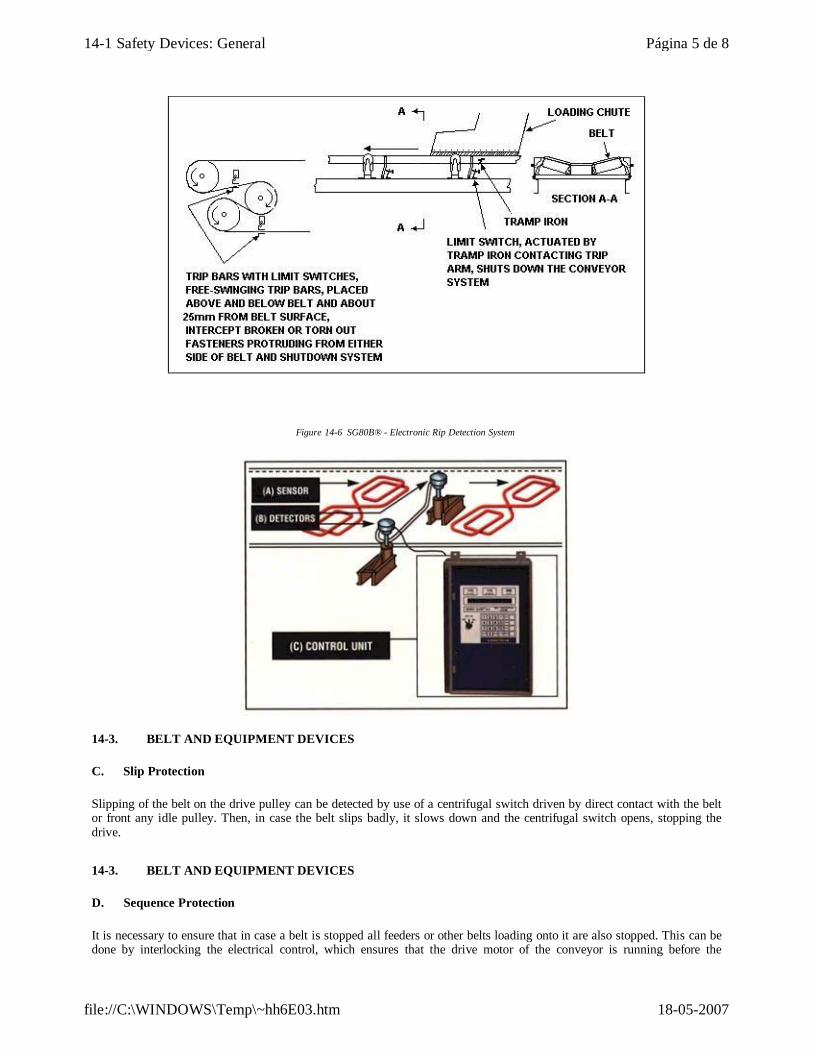
Figure 14-6 SG80B® - Electronic Rip Detection System
14-3. BELT AND EQUIPMENT DEVICES
C. Slip Protection
Slipping of the belt on the drive pulley can be detected by use of a centrifugal switch driven by direct contact with the belt or front any idle pulley. Then, in case the belt slips badly, it slows down and the centrifugal switch opens, stopping the drive.
14-3. BELT AND EQUIPMENT DEVICES
D. Sequence Protection
It is necessary to ensure that in case a belt is stopped all feeders or other belts loading onto it are also stopped. This can be done by interlocking the electrical control, which ensures that the drive motor of the conveyor is running before the
Página 5 de 814-1 Safety Devices: General
18-05-2007file://C:\WINDOWS\Temp\~hh6E03.htm
feeding belts can start, but does not ensure that the belt itself is running. To be sure that the belt itself is moving at proper speed before starting to load it, indication can be taken from the belt by a centrifugal switch as described under Section 14-3C. A centrifugal switch for sequence protection will be connected into the control of all belts or feeders loading the belt on which it is located.
14-3. BELT AND EQUIPMENT DEVICES
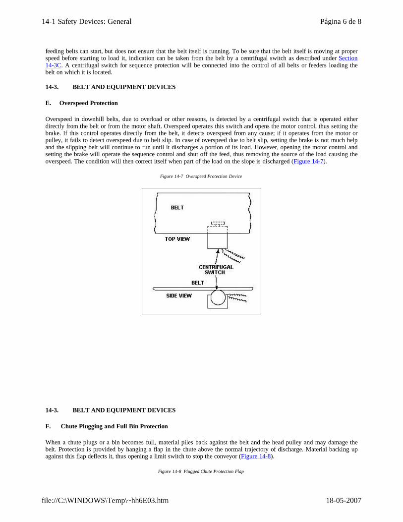
E. Overspeed Protection
Overspeed in downhill belts, due to overload or other reasons, is detected by a centrifugal switch that is operated either directly from the belt or from the motor shaft. Overspeed operates this switch and opens the motor control, thus setting the brake. If this control operates directly from the belt, it detects overspeed from any cause; if it operates from the motor or pulley, it fails to detect overspeed due to belt slip. In case of overspeed due to belt slip, setting the brake is not much help and the slipping belt will continue to run until it discharges a portion of its load. However, opening the motor control and setting the brake will operate the sequence control and shut off the feed, thus removing the source of the load causing the overspeed. The condition will then correct itself when part of the load on the slope is discharged (Figure 14-7).
Figure 14-7 Overspeed Protection Device
14-3. BELT AND EQUIPMENT DEVICES
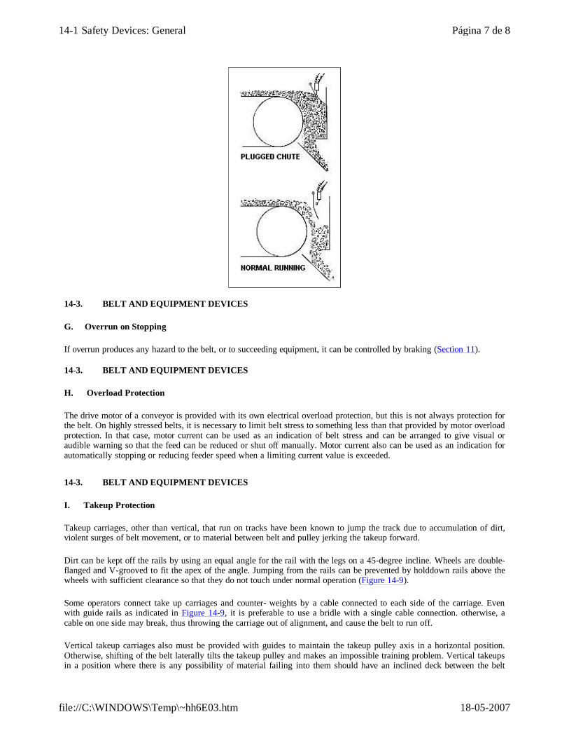
F. Chute Plugging and Full Bin Protection
When a chute plugs or a bin becomes full, material piles back against the belt and the head pulley and may damage the belt. Protection is provided by hanging a flap in the chute above the normal trajectory of discharge. Material backing up against this flap deflects it, thus opening a limit switch to stop the conveyor (Figure 14-8).
Figure 14-8 Plugged Chute Protection Flap
Página 6 de 814-1 Safety Devices: General
18-05-2007file://C:\WINDOWS\Temp\~hh6E03.htm
14-3. BELT AND EQUIPMENT DEVICES
G. Overrun on Stopping
If overrun produces any hazard to the belt, or to succeeding equipment, it can be controlled by braking (Section 11).
14-3. BELT AND EQUIPMENT DEVICES
H. Overload Protection
The drive motor of a conveyor is provided with its own electrical overload protection, but this is not always protection for the belt. On highly stressed belts, it is necessary to limit belt stress to something less than that provided by motor overload protection. In that case, motor current can be used as an indication of belt stress and can be arranged to give visual or audible warning so that the feed can be reduced or shut off manually. Motor current also can be used as an indication for automatically stopping or reducing feeder speed when a limiting current value is exceeded.
14-3. BELT AND EQUIPMENT DEVICES
I. Takeup Protection
Takeup carriages, other than vertical, that run on tracks have been known to jump the track due to accumulation of dirt, violent surges of belt movement, or to material between belt and pulley jerking the takeup forward.
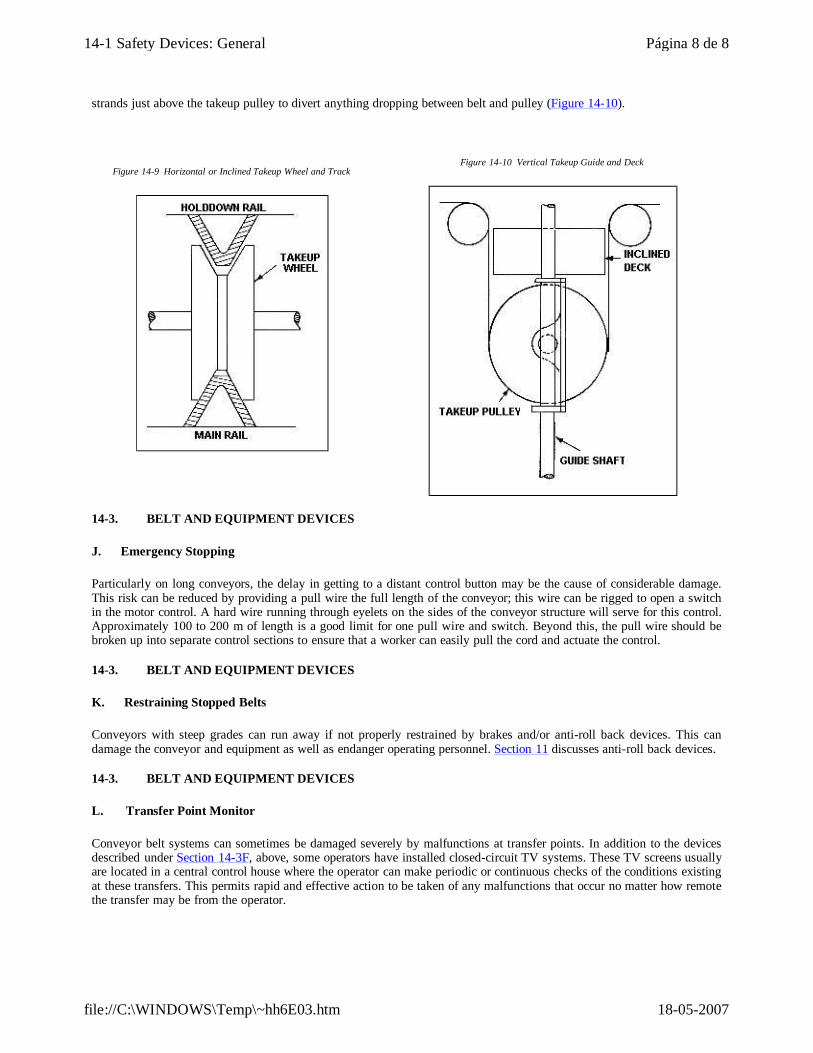
Dirt can be kept off the rails by using an equal angle for the rail with the legs on a 45-degree incline. Wheels are double-flanged and V-grooved to fit the apex of the angle. Jumping from the rails can be prevented by holddown rails above the wheels with sufficient clearance so that they do not touch under normal operation (Figure 14-9).
Some operators connect take up carriages and counter- weights by a cable connected to each side of the carriage. Even with guide rails as indicated in Figure 14-9, it is preferable to use a bridle with a single cable connection. otherwise, a cable on one side may break, thus throwing the carriage out of alignment, and cause the belt to run off.
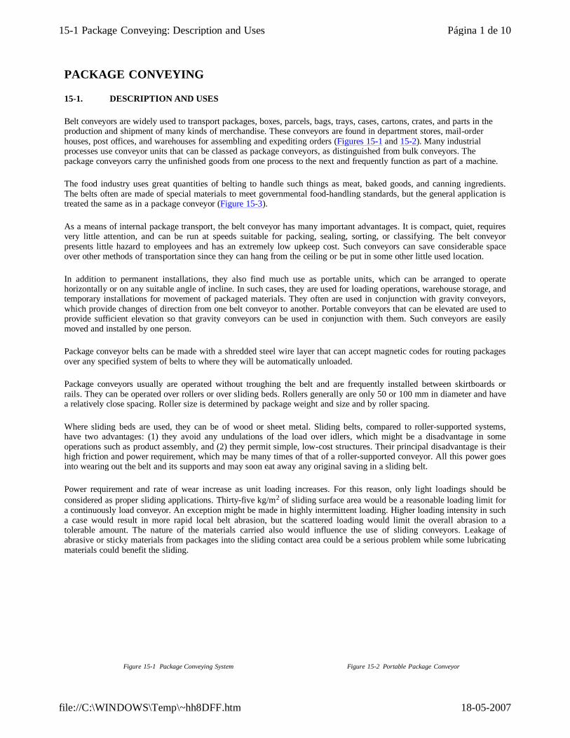
Vertical takeup carriages also must be provided with guides to maintain the takeup pulley axis in a horizontal position. Otherwise, shifting of the belt laterally tilts the takeup pulley and makes an impossible training problem. Vertical takeups in a position where there is any possibility of material failing into them should have an inclined deck between the belt
Página 7 de 814-1 Safety Devices: General
18-05-2007file://C:\WINDOWS\Temp\~hh6E03.htm
strands just above the takeup pulley to divert anything dropping between belt and pulley (Figure 14-10).
Figure 14-9 Horizontal or Inclined Takeup Wheel and Track
Figure 14-10 Vertical Takeup Guide and Deck
14-3. BELT AND EQUIPMENT DEVICES
J. Emergency Stopping
Particularly on long conveyors, the delay in getting to a distant control button may be the cause of considerable damage. This risk can be reduced by providing a pull wire the full length of the conveyor; this wire can be rigged to open a switch in the motor control. A hard wire running through eyelets on the sides of the conveyor structure will serve for this control. Approximately 100 to 200 m of length is a good limit for one pull wire and switch. Beyond this, the pull wire should be broken up into separate control sections to ensure that a worker can easily pull the cord and actuate the control.
14-3. BELT AND EQUIPMENT DEVICES
K. Restraining Stopped Belts
Conveyors with steep grades can run away if not properly restrained by brakes and/or anti-roll back devices. This can damage the conveyor and equipment as well as endanger operating personnel. Section 11 discusses anti-roll back devices.
14-3. BELT AND EQUIPMENT DEVICES
L. Transfer Point Monitor
Conveyor belt systems can sometimes be damaged severely by malfunctions at transfer points. In addition to the devices described under Section 14-3F, above, some operators have installed closed-circuit TV systems. These TV screens usually are located in a central control house where the operator can make periodic or continuous checks of the conditions existing at these transfers. This permits rapid and effective action to be taken of any malfunctions that occur no matter how remote the transfer may be from the operator.
Página 8 de 814-1 Safety Devices: General
18-05-2007file://C:\WINDOWS\Temp\~hh6E03.htm
PACKAGE CONVEYING
15-1. DESCRIPTION AND USES
Belt conveyors are widely used to transport packages, boxes, parcels, bags, trays, cases, cartons, crates, and parts in the production and shipment of many kinds of merchandise. These conveyors are found in department stores, mail-order houses, post offices, and warehouses for assembling and expediting orders (Figures 15-1 and 15-2). Many industrial processes use conveyor units that can be classed as package conveyors, as distinguished from bulk conveyors. The package conveyors carry the unfinished goods from one process to the next and frequently function as part of a machine.
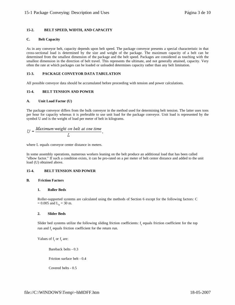
The food industry uses great quantities of belting to handle such things as meat, baked goods, and canning ingredients. The belts often are made of special materials to meet governmental food-handling standards, but the general application is treated the same as in a package conveyor (Figure 15-3).
As a means of internal package transport, the belt conveyor has many important advantages. It is compact, quiet, requires very little attention, and can be run at speeds suitable for packing, sealing, sorting, or classifying. The belt conveyor presents little hazard to employees and has an extremely low upkeep cost. Such conveyors can save considerable space over other methods of transportation since they can hang from the ceiling or be put in some other little used location.
In addition to permanent installations, they also find much use as portable units, which can be arranged to operate horizontally or on any suitable angle of incline. In such cases, they are used for loading operations, warehouse storage, and temporary installations for movement of packaged materials. They often are used in conjunction with gravity conveyors, which provide changes of direction from one belt conveyor to another. Portable conveyors that can be elevated are used to provide sufficient elevation so that gravity conveyors can be used in conjunction with them. Such conveyors are easily moved and installed by one person.
Package conveyor belts can be made with a shredded steel wire layer that can accept magnetic codes for routing packages over any specified system of belts to where they will be automatically unloaded.
Package conveyors usually are operated without troughing the belt and are frequently installed between skirtboards or rails. They can be operated over rollers or over sliding beds. Rollers generally are only 50 or 100 mm in diameter and have a relatively close spacing. Roller size is determined by package weight and size and by roller spacing.
Where sliding beds are used, they can be of wood or sheet metal. Sliding belts, compared to roller-supported systems, have two advantages: (1) they avoid any undulations of the load over idlers, which might be a disadvantage in some operations such as product assembly, and (2) they permit simple, low-cost structures. Their principal disadvantage is their high friction and power requirement, which may be many times of that of a roller-supported conveyor. All this power goes into wearing out the belt and its supports and may soon eat away any original saving in a sliding belt.
Power requirement and rate of wear increase as unit loading increases. For this reason, only light loadings should be considered as proper sliding applications. Thirty-five kg/m2 of sliding surface area would be a reasonable loading limit for a continuously load conveyor. An exception might be made in highly intermittent loading. Higher loading intensity in such a case would result in more rapid local belt abrasion, but the scattered loading would limit the overall abrasion to a tolerable amount. The nature of the materials carried also would influence the use of sliding conveyors. Leakage of abrasive or sticky materials from packages into the sliding contact area could be a serious problem while some lubricating materials could benefit the sliding.
Figure 15-1 Package Conveying System Figure 15-2 Portable Package Conveyor
Página 1 de 1015-1 Package Conveying: Description and Uses
18-05-2007file://C:\WINDOWS\Temp\~hh8DFF.htm
Figure 15-3 Food Handling Conveyors
15-2. BELT WIDTH, SPEED, AND CAPACITY
A. Belt Width
Belt widths should be determined from the greatest dimension of the largest package to be transported except (1) where the greatest dimension is consistently kept longitudinal and (2) where packages are of small size and belt width is determined from the standpoint of volumetric capacity. In the latter case, probable arrangements of packages on the belt, sufficient to give required capacity, must be assumed and belt width selected to suit such arrangements.
When packages of uniform size are handled, a belt of less width than the unit size can be used by providing rails to center the package. A good example is the handling of finished tires lying flat on the belt.
Where various size packages are carried, the rails must be kept at or near the belt edges so small packages are not lost. In this case, the width of the belt must provide for the largest package, plus clearance, or for the maximum cross-sectional load of smaller packages, whichever is greater.
15-2. BELT WIDTH, SPEED, AND CAPACITY
B. Belt Speed
Package belt speeds are customarily between 0.25 and 1 m/s. Department store package conveyors run at speeds or 0.5 to 0.75 m/s. In assembly operations on belt conveyors, speed may be less than 0.25 m/s.
Página 2 de 1015-1 Package Conveying: Description and Uses
18-05-2007file://C:\WINDOWS\Temp\~hh8DFF.htm
15-2. BELT SPEED, WIDTH, AND CAPACITY
C. Belt Capacity
As in any conveyor belt, capacity depends upon belt speed. The package conveyor presents a special characteristic in that cross-sectional load is determined by the size and weight of the package. The maximum capacity of a belt can be determined from the smallest dimension of the package and the belt speed. Packages are considered as touching with the smallest dimension in the direction of belt travel. This represents the ultimate, and not generally attained, capacity. Very often the rate at which packages can be loaded or unloaded determines capacity rather than any belt limitation.
15-3. PACKAGE CONVEYOR DATA TABULATION
All possible conveyor data should be accumulated before proceeding with tension and power calculations.
15-4. BELT TENSION AND POWER
A. Unit Load Factor (U)
The package conveyor differs from the bulk conveyor in the method used for determining belt tension. The latter uses tons per hour for capacity whereas it is preferable to use unit load for the package conveyor. Unit load is represented by the symbol U and is the weight of load per meter of belt in kilograms.
where L equals conveyor center distance in meters.
In some assembly operations, numerous workers leaning on the belt produce an additional load that has been called "elbow factor." If such a condition exists, it can be pro-rated on a per meter of belt center distance and added to the unit load (U) obtained above.
15-4. BELT TENSION AND POWER
B. Friction Factors
1. Roller Beds
Roller-supported systems are calculated using the methods of Section 6 except for the following factors: C = 0.005 and Lo = 30 m.
2. Slider Beds
Slider bed systems utilize the following sliding friction coefficients: ft equals friction coefficient for the top run and fr equals friction coefficient for the return run.
Values of ft or fr are:
Bareback belts - 0.3
Friction surface belt - 0.4
Covered belts - 0.5
Página 3 de 1015-1 Package Conveying: Description and Uses
18-05-2007file://C:\WINDOWS\Temp\~hh8DFF.htm
15-4. BELT TENSION AND POWER
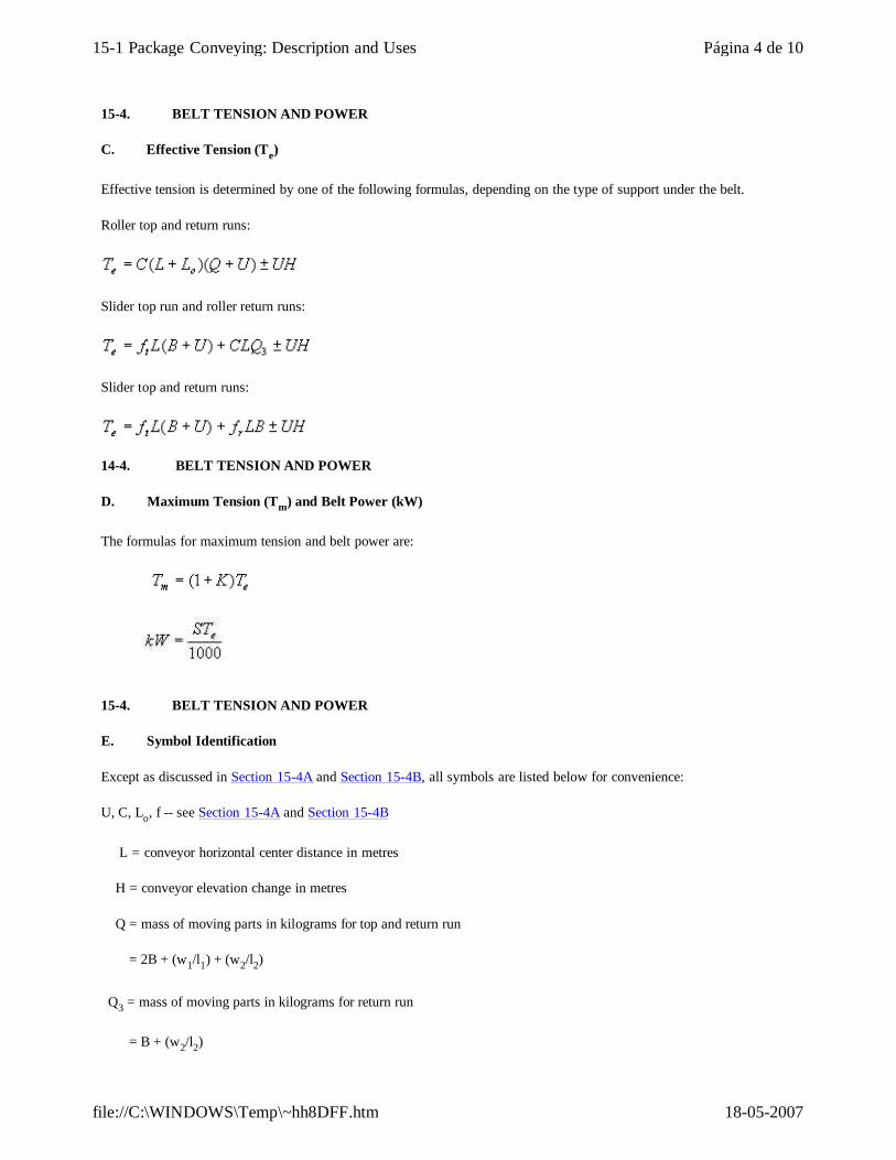
C. Effective Tension (Te)
Effective tension is determined by one of the following formulas, depending on the type of support under the belt.
Roller top and return runs:
Slider top run and roller return runs:
Slider top and return runs:
14-4. BELT TENSION AND POWER
D. Maximum Tension (Tm) and Belt Power (kW)
The formulas for maximum tension and belt power are:
15-4. BELT TENSION AND POWER
E. Symbol Identification
Except as discussed in Section 15-4A and Section 15-4B, all symbols are listed below for convenience:
U, C, Lo, f -- see Section 15-4A and Section 15-4B
L = conveyor horizontal center distance in metres
H = conveyor elevation change in metres
Q = mass of moving parts in kilograms for top and return run
= 2B + (w1/l1) + (w2/l2)
Q3 = mass of moving parts in kilograms for return run
= B + (w2/l2)
Página 4 de 1015-1 Package Conveying: Description and Uses
18-05-2007file://C:\WINDOWS\Temp\~hh8DFF.htm
B = belt mass in kilograms per metre
w1, w2 = mass of moving idler parts for top and return runs, respectively, in kilograms
l1,l2 = spacing of top and return idlers, respectively, in metres
K = drive factor (Section 9)
g = gravitational acceleration = 9.8 m/s²
15-4. BELT TENSION AND POWER
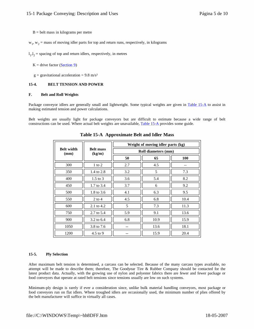
F. Belt and Roll Weights
Package conveyor idlers are generally small and lightweight. Some typical weights are given in Table 15-A to assist in making estimated tension and power calculations.
Belt weights are usually light for package conveyors but are difficult to estimate because a wide range of belt constructions can be used. Where actual belt weights are unavailable, Table 15-A provides some guide.
Table 15-A Approximate Belt and Idler Mass
Belt width (mm)
Belt mass (kg/m)
Weight of moving idler parts (kg)
Roll diameters (mm)
50 65 100
300 1 to 2 2.7 4.5 --
350 1.4 to 2.8 3.2 5 7.3
400 1.5 to 3 3.6 5.4 8.2
450 1.7 to 3.4 3.7 6 9.2
500 1.8 to 3.6 4.1 6.3 9.5
550 2 to 4 4.5 6.8 10.4
600 2.1 to 4.2 5 7.3 11.3
750 2.7 to 5.4 5.9 9.1 13.6
900 3.2 to 6.4 6.8 10.9 15.9
1050 3.8 to 7.6 -- 13.6 18.1
1200 4.5 to 9 -- 15.9 20.4
15-5. Ply Selection
After maximum belt tension is determined, a carcass can be selected. Because of the many carcass types available, no attempt will be made to describe them; therefore, The Goodyear Tire & Rubber Company should be contacted for the latest product data. Actually, with the growing use of nylon and polyester fabrics there are fewer and fewer package or food conveyors that operate at rated belt tensions since tensions usually are low on such systems.
Minimum-ply design is rarely if ever a consideration since, unlike bulk material handling conveyors, most package or food conveyors run on flat idlers. Where troughed idlers are occasionally used, the minimum number of plies offered by the belt manufacturer will suffice in virtually all cases.
Página 5 de 1015-1 Package Conveying: Description and Uses
18-05-2007file://C:\WINDOWS\Temp\~hh8DFF.htm
Where neither tension nor minimum-ply design is a factor, the final choice may be a matter of personal preference, economics, availability, and previous belt history or it may be dictated by some operating feature such as impact, heat, oil, or moisture.
15-6. PULLEY SIZES
Pulley diameter can be selected from tables provided for the carcass selected, taking into consideration the percentage of rated tension at which the package belt will operate. Pulley diameter sometimes must be reduced further due to space limitations. The penalty for reducing the pulley diameter below that justified by low tension, low speed, and intermittent operation is a reduction in ultimate belt life.
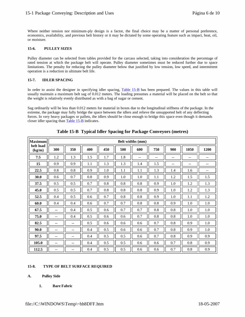
15-7. IDLER SPACING
In order to assist the designer in specifying idler spacing, Table 15-B has been prepared. The values in this table will usually maintain a maximum belt sag of 0.012 meters. The loading presumes a material will be placed on the belt so that the weight is relatively evenly distributed as with a bag of sugar or cement.
Sag ordinarily will be less than 0.012 meters for material in boxes due to the longitudinal stiffness of the package. In the extreme, the package may fully bridge the space between the idlers and relieve the unsupported belt of any deflecting forces. In very heavy packages or pallets, the idlers should be close enough to bridge this space even though it demands closer idler spacing than Table 15-B indicates.
Table 15-B Typical Idler Spacing for Package Conveyors (metres)
Maximum belt load (kg/m)
Belt widths (mm)
300 350 400 450 500 600 750 900 1050 1200
7.5 1.2 1.3 1.5 1.7 1.8 -- -- -- -- --
15 0.9 0.9 1.1 1.3 1.3 1.4 1.5 -- -- --
22.5 0.8 0.8 0.9 1.0 1.1 1.1 1.3 1.4 1.6 --
30.0 0.6 0.7 0.8 0.9 1.0 1.0 1.1 1.2 1.5 1.5
37.5 0.5 0.5 0.7 0.8 0.8 0.8 0.9 1.0 1.2 1.3
45.0 0.5 0.5 0.7 0.8 0.8 0.8 0.9 1.0 1.2 1.3
52.5 0.4 0.5 0.6 0.7 0.8 0.8 0.9 1.0 1.1 1.2
60.0 0.4 0.4 0.6 0.7 0.7 0.8 0.8 0.9 1.0 1.0
67.5 -- 0.4 0.5 0.6 0.7 0.7 0.8 0.8 1.0 1.0
75.0 -- 0.4 0.5 0.6 0.6 0.7 0.8 0.8 1.0 1.0
82.5 -- -- 0.5 0.6 0.6 0.6 0.7 0.8 0.9 1.0
90.0 -- -- 0.4 0.5 0.6 0.6 0.7 0.8 0.9 1.0
97.5 -- -- 0.4 0.5 0.5 0.6 0.7 0.8 0.9 0.9
105.0 -- -- 0.4 0.5 0.5 0.6 0.6 0.7 0.8 0.9
112.5 -- -- 0.4 0.5 0.5 0.6 0.6 0.7 0.8 0.9
15-8. TYPE OF BELT SURFACE REQUIRED
A. Pulley Side
1. Bare Fabric
Página 6 de 1015-1 Package Conveying: Description and Uses
18-05-2007file://C:\WINDOWS\Temp\~hh8DFF.htm
Bare fabric often is the first choice of belt surface when the pulley side runs on a slider bed because of a lower friction coefficient. However, the low friction sometimes means that more belt tension is required to prevent drive slippage. Bare fabric also is used over roller supports, but there is rarely a need for such a selection such as with the slider bed.
2. Frictioned Fabric Surface
Frictioned fabric surface is widely used with roller-supported belts and also works well with most slider beds.
3. Smooth Rubber Covers
Where the carcass must be protected from some undesirable substance, a rubber cover can be specified. It should be avoided if at all possible on slider beds although, in some cases, special compounds are possible that minimize friction problems.
15-8. TYPE OF BELT SURFACE REQUIRED
B. Carrying Side
1. Bare Fabric
Where the system is level, or nearly so, and where the belt is to slide beneath the packages, as with gates or plows, a bare fabric surface should be used.
2. Frictioned Fabric Surface
Where abrasion is no factor and sliding of the belt beneath the package (as in Item 1) is not important, a friction surface belt is adequate. This surface is suitable for belts that are level or that have only moderate inclines or declines.
3. Smooth Rubber Cover
Where packages or containers are abrasive or where the carcass is to be protected against moisture or other deleterious substances, a rubber cover should be specified. Here again, the belt should be level or have only moderate inclines or declines.
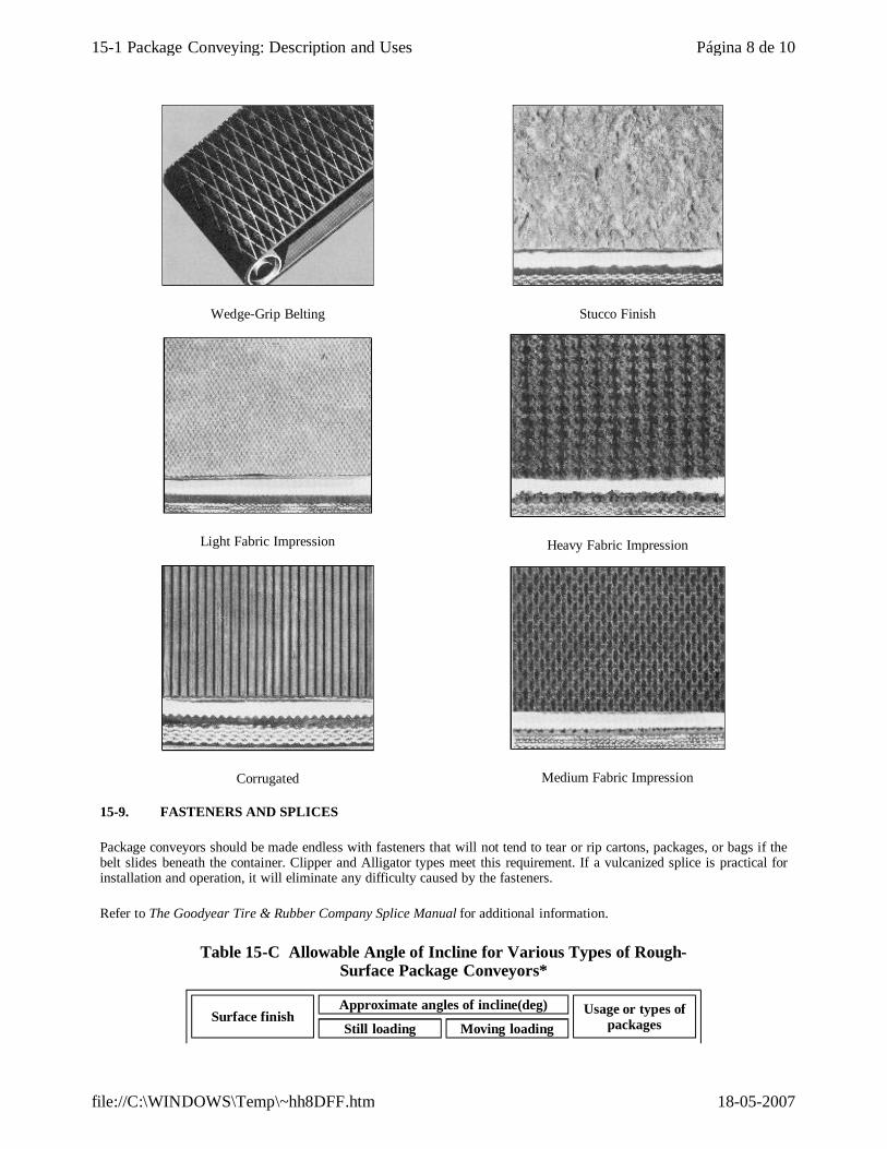
4. Rough Top Conveyors
The main object of specifying a rough surface conveyor is to increase the coefficient of friction between the belt and the package and consequently the incline or decline permissible. Various types of rough-top surfaces are shown in Figure 15-4.
The maximum angle of incline or decline for operation of a package conveyor depends, in most cases, upon the coefficient of friction between the package and the belt. In certain cases, the belt surface may provide a coefficient so high that the maximum angle is determined by the tendency of the conveyed material to roll on the belt. Such a material would be sugar or cement packed in cloth bags.
Optimum angles are desired to provide a conveyor system as restricted in space as possible. Angles of incline that can be obtained from the various rough top belts are given in Table 15-C.
Figure 15-4 Rough-Top Conveyor Surfaces
Página 7 de 1015-1 Package Conveying: Description and Uses
18-05-2007file://C:\WINDOWS\Temp\~hh8DFF.htm
Wedge-Grip Belting
Stucco Finish
Light Fabric Impression
Heavy Fabric Impression
Corrugated
Medium Fabric Impression
15-9. FASTENERS AND SPLICES
Package conveyors should be made endless with fasteners that will not tend to tear or rip cartons, packages, or bags if the belt slides beneath the container. Clipper and Alligator types meet this requirement. If a vulcanized splice is practical for installation and operation, it will eliminate any difficulty caused by the fasteners.
Refer to The Goodyear Tire & Rubber Company Splice Manual for additional information.
Table 15-C Allowable Angle of Incline for Various Types of Rough-Surface Package Conveyors*
Surface finishApproximate angles of incline(deg) Usage or types of
packagesStill loading Moving loading
Página 8 de 1015-1 Package Conveying: Description and Uses
18-05-2007file://C:\WINDOWS\Temp\~hh8DFF.htm
*All angles of incline presume relatively clean conditions of operation. Dirty conditions may reduce the operating angle as much as 5 degrees.
Wedge grip 30 35General purpose;
cartons, rough cloth, sacks, etc.
Corrugated 25 28
Wood, metal, or corrugated
containers; useful where side loading
or unloading is desired
Stucco 25 28
Mail bags or other cloth bags can be
loaded or unloaded by sliding any
direction
Light fabric impression -- --
Primarily for packaged food
products
Heavy fabric impression 25 30
General purpose; cartons, rough cloth,
sacks, etc.
Medium fabric impression 25 28 Cartons, rough cloth,
sacks, etc.
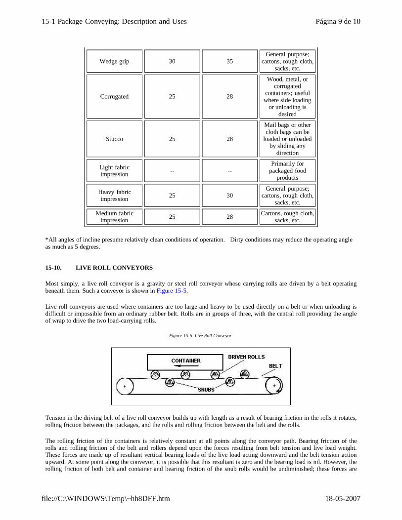
15-10. LIVE ROLL CONVEYORS
Most simply, a live roll conveyor is a gravity or steel roll conveyor whose carrying rolls are driven by a belt operating beneath them. Such a conveyor is shown in Figure 15-5.
Live roll conveyors are used where containers are too large and heavy to be used directly on a belt or when unloading is difficult or impossible from an ordinary rubber belt. Rolls are in groups of three, with the central roll providing the angle of wrap to drive the two load-carrying rolls.
Figure 15-5 Live Roll Conveyor
Tension in the driving belt of a live roll conveyor builds up with length as a result of bearing friction in the rolls it rotates, rolling friction between the packages, and the rolls and rolling friction between the belt and the rolls.
The rolling friction of the containers is relatively constant at all points along the conveyor path. Bearing friction of the rolls and rolling friction of the belt and rollers depend upon the forces resulting from belt tension and live load weight. These forces are made up of resultant vertical bearing loads of the live load acting downward and the belt tension action upward. At some point along the conveyor, it is possible that this resultant is zero and the bearing load is nil. However, the rolling friction of both belt and container and bearing friction of the snub rolls would be undiminished; these forces are
Página 9 de 1015-1 Package Conveying: Description and Uses
18-05-2007file://C:\WINDOWS\Temp\~hh8DFF.htm
larger than the load roller bearing friction.
As a result, effective pull on the belt builds up very rapidly with increase in length of the conveyor, in almost any case faster than a direct proportion to length.
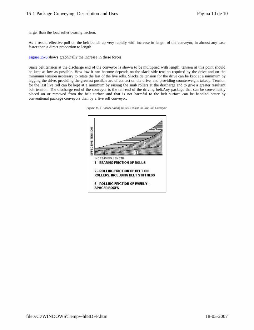
Figure 15-6 shows graphically the increase in these forces.
Since belt tension at the discharge end of the conveyor is shown to be multiplied with length, tension at this point should be kept as low as possible. How low it can become depends on the slack side tension required by the drive and on the minimum tension necessary to rotate the last of the live rolls. Slackside tension for the drive can be kept at a minimum by lagging the drive, providing the greatest possible arc of contact on the drive, and providing counterweight takeup. Tension for the last live roll can be kept at a minimum by raising the snub rollers at the discharge end to give a greater resultant belt tension. The discharge end of the conveyor is the tail end of the driving belt.Any package that can be conveniently placed on or removed from the belt surface and that is not harmful to the belt surface can be handled better by conventional package conveyors than by a live roll conveyor.
Figure 15-6 Forces Adding to Belt Tension in Live Roll Conveyor
Página 10 de 1015-1 Package Conveying: Description and Uses
18-05-2007file://C:\WINDOWS\Temp\~hh8DFF.htm
GRAIN CONVEYORS AND ELEVATORS
16-1. GRAIN CONVEYOR BELTS
A. General
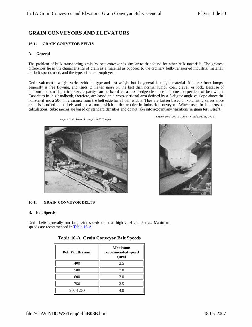
The problem of bulk transporting grain by belt conveyor is similar to that found for other bulk materials. The greatest differences lie in the characteristics of grain as a material as opposed to the ordinary bulk-transported industrial material, the belt speeds used, and the types of idlers employed.
Grain volumetric weight varies with the type and test weight but in general is a light material. It is free from lumps, generally is free flowing, and tends to flatten more on the belt than normal lumpy coal, gravel, or rock. Because of uniform and small particle size, capacity can be based on a lesser edge clearance and one independent of belt width. Capacities in this handbook, therefore, are based on a cross-sectional area defined by a 5-degree angle of slope above the horizontal and a 50-mm clearance from the belt edge for all belt widths. They are further based on volumetric values since grain is handled as bushels and not as tons, which is the practice in industrial conveyors. Where used in belt tension calculations, cubic metres are based on standard densities and do not take into account any variations in grain test weight.
Figure 16-1 Grain Conveyor with Tripper
Figure 16-2 Grain Conveyor and Loading Spout
16-1. GRAIN CONVEYOR BELTS
B. Belt Speeds
Grain belts generally run fast, with speeds often as high as 4 and 5 m/s. Maximum speeds are recommended in Table 16-A.
Table 16-A Grain Conveyor Belt Speeds
Belt Width (mm)Maximum
recommended speed (m/s)
400 2.5
500 3.0
600 3.0
750 3.5
900-1200 4.0
Página 1 de 2016-1A Grain Conveyors and Elevators: Grain Conveyor Belts: General
18-05-2007file://C:\WINDOWS\Temp\~hhB08B.htm
16-1. GRAIN CONVEYOR BELTS
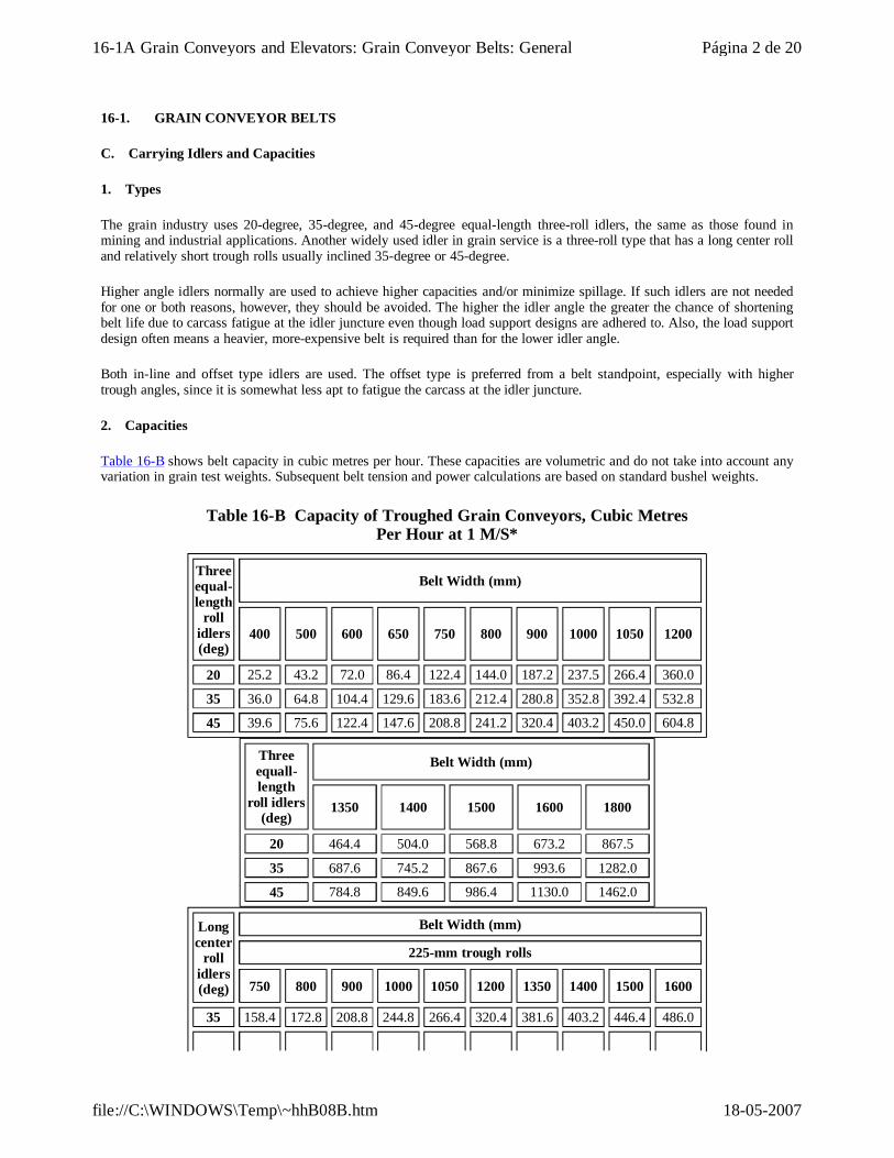
C. Carrying Idlers and Capacities
1. Types
The grain industry uses 20-degree, 35-degree, and 45-degree equal-length three-roll idlers, the same as those found in mining and industrial applications. Another widely used idler in grain service is a three-roll type that has a long center roll and relatively short trough rolls usually inclined 35-degree or 45-degree.
Higher angle idlers normally are used to achieve higher capacities and/or minimize spillage. If such idlers are not needed for one or both reasons, however, they should be avoided. The higher the idler angle the greater the chance of shortening belt life due to carcass fatigue at the idler juncture even though load support designs are adhered to. Also, the load support design often means a heavier, more-expensive belt is required than for the lower idler angle.
Both in-line and offset type idlers are used. The offset type is preferred from a belt standpoint, especially with higher trough angles, since it is somewhat less apt to fatigue the carcass at the idler juncture.
2. Capacities
Table 16-B shows belt capacity in cubic metres per hour. These capacities are volumetric and do not take into account any variation in grain test weights. Subsequent belt tension and power calculations are based on standard bushel weights.
Table 16-B Capacity of Troughed Grain Conveyors, Cubic Metres Per Hour at 1 M/S*
Three equal-length
roll idlers (deg)
Belt Width (mm)
400 500 600 650 750 800 900 1000 1050 1200
20 25.2 43.2 72.0 86.4 122.4 144.0 187.2 237.5 266.4 360.0
35 36.0 64.8 104.4 129.6 183.6 212.4 280.8 352.8 392.4 532.8
45 39.6 75.6 122.4 147.6 208.8 241.2 320.4 403.2 450.0 604.8
Three equall-length
roll idlers (deg)
Belt Width (mm)
1350 1400 1500 1600 1800
20 464.4 504.0 568.8 673.2 867.5
35 687.6 745.2 867.6 993.6 1282.0
45 784.8 849.6 986.4 1130.0 1462.0
Long center
roll idlers (deg)
Belt Width (mm)
225-mm trough rolls
750 800 900 1000 1050 1200 1350 1400 1500 1600
35 158.4 172.8 208.8 244.8 266.4 320.4 381.6 403.2 446.4 486.0
Página 2 de 2016-1A Grain Conveyors and Elevators: Grain Conveyor Belts: General
18-05-2007file://C:\WINDOWS\Temp\~hhB08B.htm
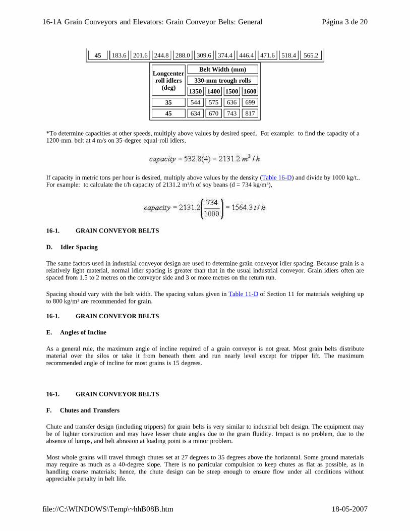
*To determine capacities at other speeds, multiply above values by desired speed. For example: to find the capacity of a 1200-mm. belt at 4 m/s on 35-degree equal-roll idlers,
If capacity in metric tons per hour is desired, multiply above values by the density (Table 16-D) and divide by 1000 kg/t.. For example: to calculate the t/h capacity of 2131.2 m³/h of soy beans (d = 734 kg/m³),
45 183.6 201.6 244.8 288.0 309.6 374.4 446.4 471.6 518.4 565.2
Longcenter roll idlers
(deg)
Belt Width (mm)
330-mm trough rolls
1350 1400 1500 1600
35 544 575 636 699
45 634 670 743 817
16-1. GRAIN CONVEYOR BELTS
D. Idler Spacing
The same factors used in industrial conveyor design are used to determine grain conveyor idler spacing. Because grain is a relatively light material, normal idler spacing is greater than that in the usual industrial conveyor. Grain idlers often are spaced from 1.5 to 2 metres on the conveyor side and 3 or more metres on the return run.
Spacing should vary with the belt width. The spacing values given in Table 11-D of Section 11 for materials weighing up to 800 kg/m³ are recommended for grain.
16-1. GRAIN CONVEYOR BELTS
E. Angles of Incline
As a general rule, the maximum angle of incline required of a grain conveyor is not great. Most grain belts distribute material over the silos or take it from beneath them and run nearly level except for tripper lift. The maximum recommended angle of incline for most grains is 15 degrees.
16-1. GRAIN CONVEYOR BELTS
F. Chutes and Transfers
Chute and transfer design (including trippers) for grain belts is very similar to industrial belt design. The equipment may be of lighter construction and may have lesser chute angles due to the grain fluidity. Impact is no problem, due to the absence of lumps, and belt abrasion at loading point is a minor problem.
Most whole grains will travel through chutes set at 27 degrees to 35 degrees above the horizontal. Some ground materials may require as much as a 40-degree slope. There is no particular compulsion to keep chutes as flat as possible, as in handling coarse materials; hence, the chute design can be steep enough to ensure flow under all conditions without appreciable penalty in belt life.
Página 3 de 2016-1A Grain Conveyors and Elevators: Grain Conveyor Belts: General
18-05-2007file://C:\WINDOWS\Temp\~hhB08B.htm
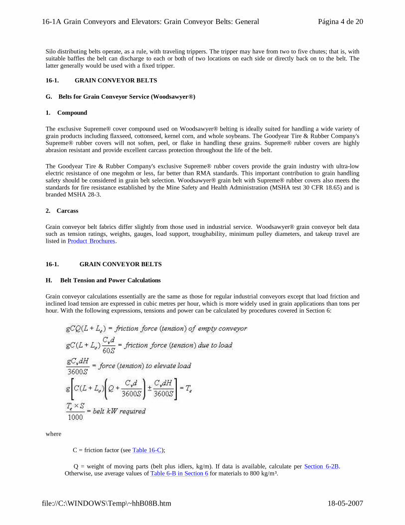
Silo distributing belts operate, as a rule, with traveling trippers. The tripper may have from two to five chutes; that is, with suitable baffles the belt can discharge to each or both of two locations on each side or directly back on to the belt. The latter generally would be used with a fixed tripper.
16-1. GRAIN CONVEYOR BELTS
G. Belts for Grain Conveyor Service (Woodsawyer®)
1. Compound
The exclusive Supreme® cover compound used on Woodsawyer® belting is ideally suited for handling a wide variety of grain products including flaxseed, cottonseed, kernel corn, and whole soybeans. The Goodyear Tire & Rubber Company's Supreme® rubber covers will not soften, peel, or flake in handling these grains. Supreme® rubber covers are highly abrasion resistant and provide excellent carcass protection throughout the life of the belt.
The Goodyear Tire & Rubber Company's exclusive Supreme® rubber covers provide the grain industry with ultra-low electric resistance of one megohm or less, far better than RMA standards. This important contribution to grain handling safety should be considered in grain belt selection. Woodsawyer® grain belt with Supreme® rubber covers also meets the standards for fire resistance established by the Mine Safety and Health Administration (MSHA test 30 CFR 18.65) and is branded MSHA 28-3.
2. Carcass
Grain conveyor belt fabrics differ slightly from those used in industrial service. Woodsawyer® grain conveyor belt data such as tension ratings, weights, gauges, load support, troughability, minimum pulley diameters, and takeup travel are listed in Product Brochures.
16-1. GRAIN CONVEYOR BELTS
H. Belt Tension and Power Calculations
Grain conveyor calculations essentially are the same as those for regular industrial conveyors except that load friction and inclined load tension are expressed in cubic metres per hour, which is more widely used in grain applications than tons per hour. With the following expressions, tensions and power can be calculated by procedures covered in Section 6:
where
C = friction factor (see Table 16-C);
Q = weight of moving parts (belt plus idlers, kg/m). If data is available, calculate per Section 6-2B. Otherwise, use average values of Table 6-B in Section 6 for materials to 800 kg/m³.
Página 4 de 2016-1A Grain Conveyors and Elevators: Grain Conveyor Belts: General
18-05-2007file://C:\WINDOWS\Temp\~hhB08B.htm
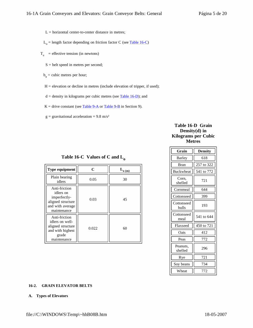
L = horizontal center-to-center distance in metres;
Lo = length factor depending on friction factor C (see Table 16-C)
Te = effective tension (in newtons)
S = belt speed in metres per second;
bu = cubic metres per hour;
H = elevation or decline in metres (include elevation of tripper, if used);
d = density in kilograms per cubic metres (see Table 16-D); and
K = drive constant (see Table 9-A or Table 9-B in Section 9).
g = gravitational acceleration = 9.8 m/s²
Table 16-C Values of C and Lo
Type equipment C Lo (m)
Plain bearing idlers 0.05 30
Anti-friction idlers on
imperfectly-aligned structure and with average
maintenance
0.03 45
Anti-friction idlers on well-
aligned structure and with highest
grade maintenance
0.022 60
Table 16-D Grain Density(d) in
Kilograms per Cubic Metres
Grain Density
Barley 618
Bran 257 to 322
Buckwheat 541 to 772
Corn, shelled 721
Cornmeal 644
Cottonseed 399
Cottonseed hulls 193
Cottonseed meal 541 to 644
Flaxseed 450 to 721
Oats 412
Peas 772
Peanuts, shelled 296
Rye 721
Soy beans 734
Wheat 772
16-2. GRAIN ELEVATOR BELTS
A. Types of Elevators
Página 5 de 2016-1A Grain Conveyors and Elevators: Grain Conveyor Belts: General
18-05-2007file://C:\WINDOWS\Temp\~hhB08B.htm
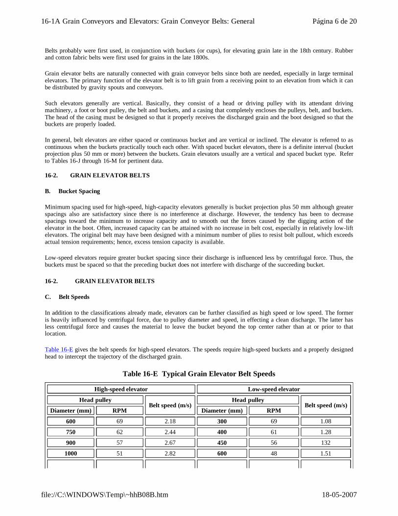
Belts probably were first used, in conjunction with buckets (or cups), for elevating grain late in the 18th century. Rubber and cotton fabric belts were first used for grains in the late 1800s.
Grain elevator belts are naturally connected with grain conveyor belts since both are needed, especially in large terminal elevators. The primary function of the elevator belt is to lift grain from a receiving point to an elevation from which it can be distributed by gravity spouts and conveyors.
Such elevators generally are vertical. Basically, they consist of a head or driving pulley with its attendant driving machinery, a foot or boot pulley, the belt and buckets, and a casing that completely encloses the pulleys, belt, and buckets. The head of the casing must be designed so that it properly receives the discharged grain and the boot designed so that the buckets are properly loaded.
In general, belt elevators are either spaced or continuous bucket and are vertical or inclined. The elevator is referred to as continuous when the buckets practically touch each other. With spaced bucket elevators, there is a definite interval (bucket projection plus 50 mm or more) between the buckets. Grain elevators usually are a vertical and spaced bucket type. Refer to Tables 16-J through 16-M for pertinent data.
16-2. GRAIN ELEVATOR BELTS
B. Bucket Spacing
Minimum spacing used for high-speed, high-capacity elevators generally is bucket projection plus 50 mm although greater spacings also are satisfactory since there is no interference at discharge. However, the tendency has been to decrease spacings toward the minimum to increase capacity and to smooth out the forces caused by the digging action of the elevator in the boot. Often, increased capacity can be attained with no increase in belt cost, especially in relatively low-lift elevators. The original belt may have been designed with a minimum number of plies to resist bolt pullout, which exceeds actual tension requirements; hence, excess tension capacity is available.
Low-speed elevators require greater bucket spacing since their discharge is influenced less by centrifugal force. Thus, the buckets must be spaced so that the preceding bucket does not interfere with discharge of the succeeding bucket.
16-2. GRAIN ELEVATOR BELTS
C. Belt Speeds
In addition to the classifications already made, elevators can be further classified as high speed or low speed. The former is heavily influenced by centrifugal force, due to pulley diameter and speed, in effecting a clean discharge. The latter has less centrifugal force and causes the material to leave the bucket beyond the top center rather than at or prior to that location.
Table 16-E gives the belt speeds for high-speed elevators. The speeds require high-speed buckets and a properly designed head to intercept the trajectory of the discharged grain.
Table 16-E Typical Grain Elevator Belt Speeds
High-speed elevator Low-speed elevator
Head pulleyBelt speed (m/s)
Head pulleyBelt speed (m/s)
Diameter (mm) RPM Diameter (mm) RPM
600 69 2.18 300 69 1.08
750 62 2.44 400 61 1.28
900 57 2.67 450 56 132
1000 51 2.82 600 48 1.51
Página 6 de 2016-1A Grain Conveyors and Elevators: Grain Conveyor Belts: General
18-05-2007file://C:\WINDOWS\Temp\~hhB08B.htm
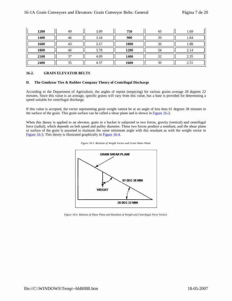
1200 49 3.09 750 43 1.69
1400 46 3.34 900 39 1.84
1600 43 3.57 1000 36 1.88
1800 40 3.78 1200 34 2.14
2100 37 4.09 1400 32 2.35
2400 35 4.37 1600 30 2.51
16-2. GRAIN ELEVATOR BELTS
D. The Goodyear Tire & Rubber Company Theory of Centrifugal Discharge
According to the Department of Agriculture, the angles of repose (emptying) for various grains average 28 degrees 22 minutes. Since this value is an average, specific grains will vary from this value, but a base is provided for determining a speed suitable for centrifugal discharge.
If this value is accepted, the vector representing grain weight cannot be at an angle of less than 61 degrees 38 minutes to the surface of the grain. This grain surface can be called a shear plane and is shown in Figure 16-3.
When this theory is applied to an elevator, grain in a bucket is subjected to two forces, gravity (vertical) and centrifugal force (radial), which depends on belt speed and pulley diameter. These two forces produce a resultant, and the shear plane or surface of the grain is assumed to maintain the same minimum angle with this resultant as with the weight vector in Figure 16-3. This theory is illustrated graphically in Figure 16-4.
Figure 16-3 Relation of Weight Vector and Grain Shear Plane
Figure 16-4 Relation of Shear Plane and Resultant of Weight and Centrifugal Force Vectors
Página 7 de 2016-1A Grain Conveyors and Elevators: Grain Conveyor Belts: General
18-05-2007file://C:\WINDOWS\Temp\~hhB08B.htm

If these forces are then applied to an actual bucket containing grain, they would arrange themselves as shown in Figures 16-5, 16-6, and 16-7, below.
Figure 16-5 Relation of Shear Plane and Force Vectors When Bucket Enters Discharge Pulley
Figure 16-6 Relation of Shear Plane and Force Vectors When Bucket is Approximately 30 Deg Up on Discharge Pulley
Figure 16-7 Relation of Shear Plane and Force Vectors When Bucket Has Passed Top Center of Discharge Pulley
Página 8 de 2016-1A Grain Conveyors and Elevators: Grain Conveyor Belts: General
18-05-2007file://C:\WINDOWS\Temp\~hhB08B.htm
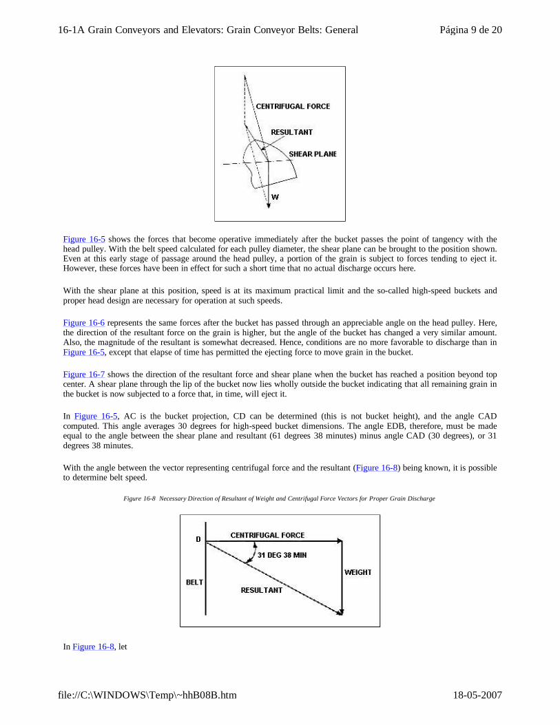
Figure 16-5 shows the forces that become operative immediately after the bucket passes the point of tangency with the head pulley. With the belt speed calculated for each pulley diameter, the shear plane can be brought to the position shown. Even at this early stage of passage around the head pulley, a portion of the grain is subject to forces tending to eject it. However, these forces have been in effect for such a short time that no actual discharge occurs here.
With the shear plane at this position, speed is at its maximum practical limit and the so-called high-speed buckets and proper head design are necessary for operation at such speeds.
Figure 16-6 represents the same forces after the bucket has passed through an appreciable angle on the head pulley. Here, the direction of the resultant force on the grain is higher, but the angle of the bucket has changed a very similar amount. Also, the magnitude of the resultant is somewhat decreased. Hence, conditions are no more favorable to discharge than in Figure 16-5, except that elapse of time has permitted the ejecting force to move grain in the bucket.
Figure 16-7 shows the direction of the resultant force and shear plane when the bucket has reached a position beyond top center. A shear plane through the lip of the bucket now lies wholly outside the bucket indicating that all remaining grain in the bucket is now subjected to a force that, in time, will eject it.
In Figure 16-5, AC is the bucket projection, CD can be determined (this is not bucket height), and the angle CAD computed. This angle averages 30 degrees for high-speed bucket dimensions. The angle EDB, therefore, must be made equal to the angle between the shear plane and resultant (61 degrees 38 minutes) minus angle CAD (30 degrees), or 31 degrees 38 minutes.
With the angle between the vector representing centrifugal force and the resultant (Figure 16-8) being known, it is possible to determine belt speed.
Figure 16-8 Necessary Direction of Resultant of Weight and Centrifugal Force Vectors for Proper Grain Discharge
In Figure 16-8, let
Página 9 de 2016-1A Grain Conveyors and Elevators: Grain Conveyor Belts: General
18-05-2007file://C:\WINDOWS\Temp\~hhB08B.htm
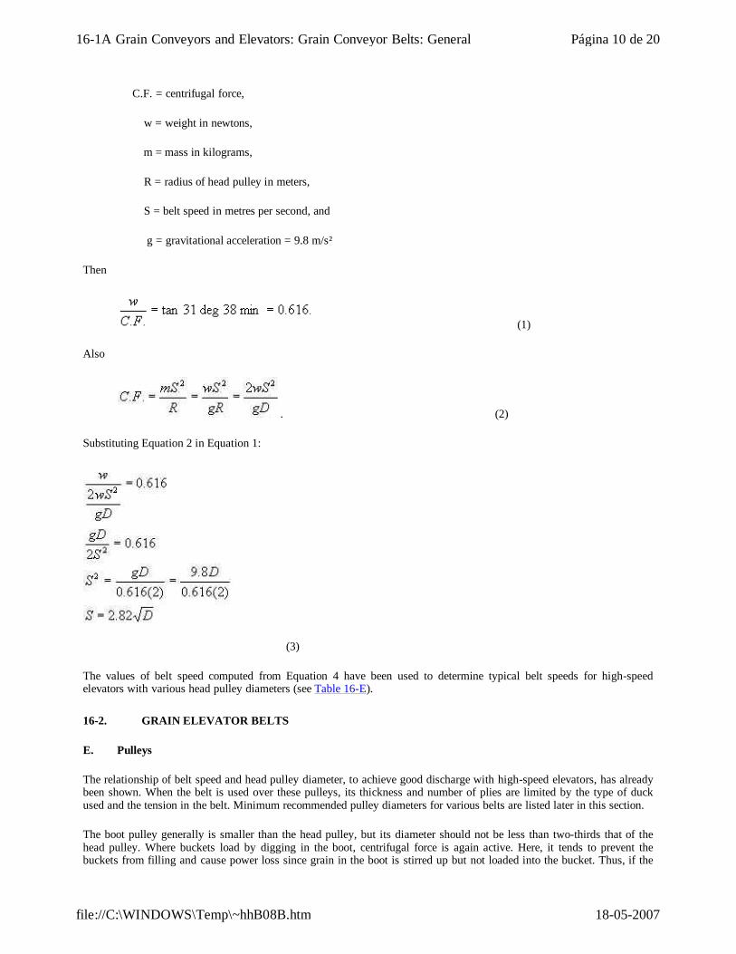
C.F. = centrifugal force,
w = weight in newtons,
m = mass in kilograms,
R = radius of head pulley in meters,
S = belt speed in metres per second, and
g = gravitational acceleration = 9.8 m/s²
Then
(1)
Also
. (2)
Substituting Equation 2 in Equation 1:
(3)
The values of belt speed computed from Equation 4 have been used to determine typical belt speeds for high-speed elevators with various head pulley diameters (see Table 16-E).
16-2. GRAIN ELEVATOR BELTS
E. Pulleys
The relationship of belt speed and head pulley diameter, to achieve good discharge with high-speed elevators, has already been shown. When the belt is used over these pulleys, its thickness and number of plies are limited by the type of duck used and the tension in the belt. Minimum recommended pulley diameters for various belts are listed later in this section.
The boot pulley generally is smaller than the head pulley, but its diameter should not be less than two-thirds that of the head pulley. Where buckets load by digging in the boot, centrifugal force is again active. Here, it tends to prevent the buckets from filling and cause power loss since grain in the boot is stirred up but not loaded into the bucket. Thus, if the
Página 10 de 2016-1A Grain Conveyors and Elevators: Grain Conveyor Belts: General
18-05-2007file://C:\WINDOWS\Temp\~hhB08B.htm
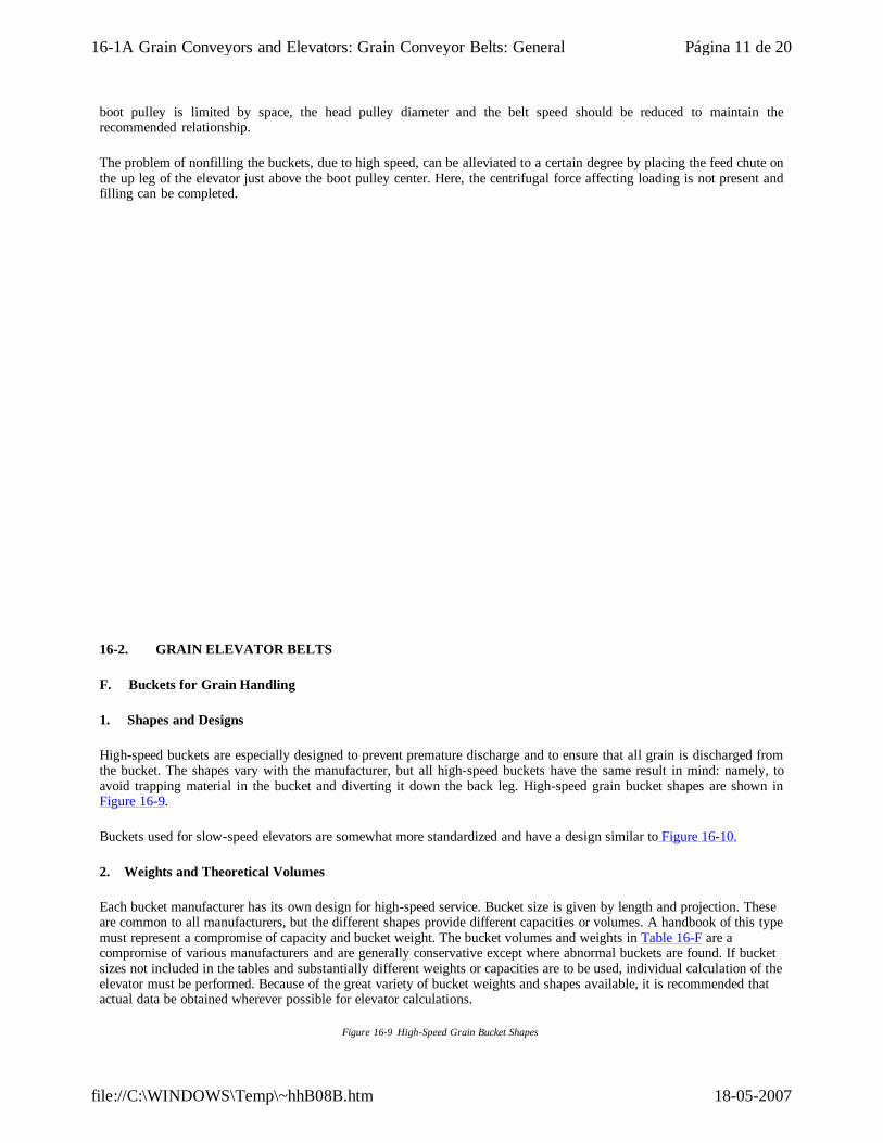
boot pulley is limited by space, the head pulley diameter and the belt speed should be reduced to maintain the recommended relationship.
The problem of nonfilling the buckets, due to high speed, can be alleviated to a certain degree by placing the feed chute on the up leg of the elevator just above the boot pulley center. Here, the centrifugal force affecting loading is not present and filling can be completed.
16-2. GRAIN ELEVATOR BELTS
F. Buckets for Grain Handling
1. Shapes and Designs
High-speed buckets are especially designed to prevent premature discharge and to ensure that all grain is discharged from the bucket. The shapes vary with the manufacturer, but all high-speed buckets have the same result in mind: namely, to avoid trapping material in the bucket and diverting it down the back leg. High-speed grain bucket shapes are shown in Figure 16-9.
Buckets used for slow-speed elevators are somewhat more standardized and have a design similar to Figure 16-10.
2. Weights and Theoretical Volumes
Each bucket manufacturer has its own design for high-speed service. Bucket size is given by length and projection. These are common to all manufacturers, but the different shapes provide different capacities or volumes. A handbook of this type must represent a compromise of capacity and bucket weight. The bucket volumes and weights in Table 16-F are a compromise of various manufacturers and are generally conservative except where abnormal buckets are found. If bucket sizes not included in the tables and substantially different weights or capacities are to be used, individual calculation of the elevator must be performed. Because of the great variety of bucket weights and shapes available, it is recommended that actual data be obtained wherever possible for elevator calculations.
Figure 16-9 High-Speed Grain Bucket Shapes
Página 11 de 2016-1A Grain Conveyors and Elevators: Grain Conveyor Belts: General
18-05-2007file://C:\WINDOWS\Temp\~hhB08B.htm
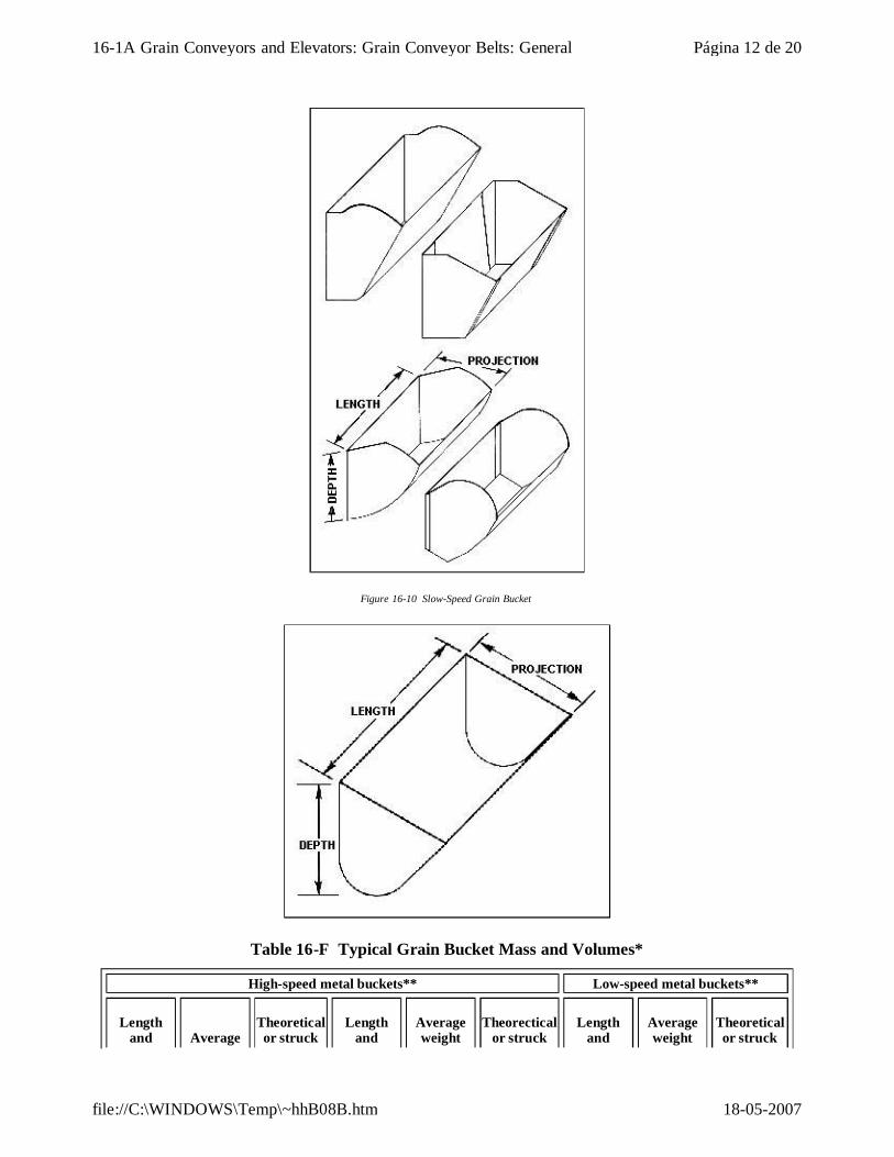
Figure 16-10 Slow-Speed Grain Bucket
Table 16-F Typical Grain Bucket Mass and Volumes*
High-speed metal buckets** Low-speed metal buckets**
Length and Average
Theoretical or struck
Length and
Average weight
Theorectical or struck
Length and
Average weight
Theoretical or struck
Página 12 de 2016-1A Grain Conveyors and Elevators: Grain Conveyor Belts: General
18-05-2007file://C:\WINDOWS\Temp\~hhB08B.htm
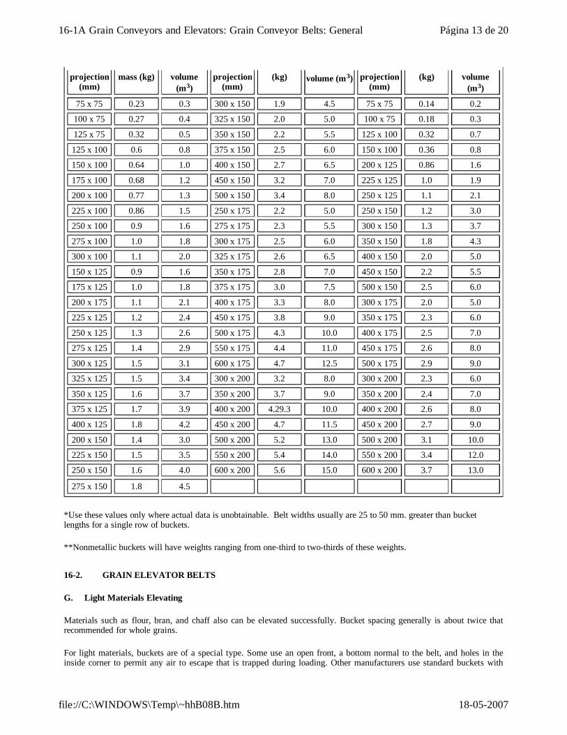
*Use these values only where actual data is unobtainable. Belt widths usually are 25 to 50 mm. greater than bucket lengths for a single row of buckets.
**Nonmetallic buckets will have weights ranging from one-third to two-thirds of these weights.
projection (mm)
mass (kg) volume (m3)
projection (mm)
(kg) volume (m3) projection (mm)
(kg) volume (m3)
75 x 75 0.23 0.3 300 x 150 1.9 4.5 75 x 75 0.14 0.2
100 x 75 0.27 0.4 325 x 150 2.0 5.0 100 x 75 0.18 0.3
125 x 75 0.32 0.5 350 x 150 2.2 5.5 125 x 100 0.32 0.7
125 x 100 0.6 0.8 375 x 150 2.5 6.0 150 x 100 0.36 0.8
150 x 100 0.64 1.0 400 x 150 2.7 6.5 200 x 125 0.86 1.6
175 x 100 0.68 1.2 450 x 150 3.2 7.0 225 x 125 1.0 1.9
200 x 100 0.77 1.3 500 x 150 3.4 8.0 250 x 125 1.1 2.1
225 x 100 0.86 1.5 250 x 175 2.2 5.0 250 x 150 1.2 3.0
250 x 100 0.9 1.6 275 x 175 2.3 5.5 300 x 150 1.3 3.7
275 x 100 1.0 1.8 300 x 175 2.5 6.0 350 x 150 1.8 4.3
300 x 100 1.1 2.0 325 x 175 2.6 6.5 400 x 150 2.0 5.0
150 x 125 0.9 1.6 350 x 175 2.8 7.0 450 x 150 2.2 5.5
175 x 125 1.0 1.8 375 x 175 3.0 7.5 500 x 150 2.5 6.0
200 x 175 1.1 2.1 400 x 175 3.3 8.0 300 x 175 2.0 5.0
225 x 125 1.2 2.4 450 x 175 3.8 9.0 350 x 175 2.3 6.0
250 x 125 1.3 2.6 500 x 175 4.3 10.0 400 x 175 2.5 7.0
275 x 125 1.4 2.9 550 x 175 4.4 11.0 450 x 175 2.6 8.0
300 x 125 1.5 3.1 600 x 175 4.7 12.5 500 x 175 2.9 9.0
325 x 125 1.5 3.4 300 x 200 3.2 8.0 300 x 200 2.3 6.0
350 x 125 1.6 3.7 350 x 200 3.7 9.0 350 x 200 2.4 7.0
375 x 125 1.7 3.9 400 x 200 4.29.3 10.0 400 x 200 2.6 8.0
400 x 125 1.8 4.2 450 x 200 4.7 11.5 450 x 200 2.7 9.0
200 x 150 1.4 3.0 500 x 200 5.2 13.0 500 x 200 3.1 10.0
225 x 150 1.5 3.5 550 x 200 5.4 14.0 550 x 200 3.4 12.0
250 x 150 1.6 4.0 600 x 200 5.6 15.0 600 x 200 3.7 13.0
275 x 150 1.8 4.5
16-2. GRAIN ELEVATOR BELTS
G. Light Materials Elevating
Materials such as flour, bran, and chaff also can be elevated successfully. Bucket spacing generally is about twice that recommended for whole grains.
For light materials, buckets are of a special type. Some use an open front, a bottom normal to the belt, and holes in the inside corner to permit any air to escape that is trapped during loading. Other manufacturers use standard buckets with
Página 13 de 2016-1A Grain Conveyors and Elevators: Grain Conveyor Belts: General
18-05-2007file://C:\WINDOWS\Temp\~hhB08B.htm
special perforations for the same purpose.
In handling light, fluffy materials, the head design should have a smooth curve about the head pulley to eliminate air currents that tend to cause turbulence. This facilitates discharge and reduces dust and back legging.
16-2. GRAIN ELEVATOR BELTS
H. Elevator and Bucket Capacities
1. Volume of Material in Each Bucket, V (m3)
When an actual volume of material in each bucket is given, then this value is to be used in subsequent calculations.
When a theoretical or struck volume of a bucket is given, then some percentage of this value also is usually provided that gives the actual amount of material in each bucket. Where no percentage is provided, then the following estimates are used:
High-speed elevator: V = 90% of theoretical or struck volume
Low-speed elevator: V = 75% of theoretical or struck volume
2. Weight of Material in Each Bucket, w (Kilograms)
Material weight in each bucket is calculated as follows:
where
V = actual volume of material in bucket in m3 and
d = material weight in kg per m2 (Table 16-D).
3. Elevator Capacity in Cubic Metres per Hour (Cv)
Elevator capacity is calculated as follows:
where
V = actual volume of material in bucket in m3,
Cv = cubic metres per hour,
S = belt speed in metres per second,
s = bucket c-c spacing in mm, and
Página 14 de 2016-1A Grain Conveyors and Elevators: Grain Conveyor Belts: General
18-05-2007file://C:\WINDOWS\Temp\~hhB08B.htm
N = number of rows of buckets across belt width.
16-2. GRAIN ELEVATOR BELTS
I. Components of Maximum Belt Tension
Maximum tension in a grain elevator has the following components:
TB = gBH = tension due to weight of belt (N)
Te is the sum of tension due to load weight in buckets g(1000mNH/s) plus tension due to picking up the load and boot pulley friction (1000mNHo/s). In these three equations, the following symbols are used:
B = belt mass in kilograms per metre,
b = bucket mass in kilograms,
s = bucket spacing in millimetres
m = mass of material in each bucket in kilograms,
N = number of rows of buckets across belt width,
H = vertical height of elevator in metres, and
Ho = height factor to allow for pickup force plus boot pulley friction
= 10m grain elevators.
16-2. GRAIN ELEVATOR BELTS
J. Maximum Tension, Tm (Newtons)
Maximum tension is the greater of the following two equations:
Tm = TB + Tb + Te
or
Tm = (1 + K)Te
where
K = 0.97 bare drive, screw takeup
Página 15 de 2016-1A Grain Conveyors and Elevators: Grain Conveyor Belts: General
18-05-2007file://C:\WINDOWS\Temp\~hhB08B.htm
= 0.80 lagged drive, screw takeup
= 0.64 bare drive, automatic takeup
= 0.50 lagged drive, automatic takeup
When the first equation is greater, the belt plus bucket weights were great enough to provide adequate tension for the drive. When the second equation is greater, additional tension is needed to provide drive tension. The amount of additional tension required is the difference between the two equations.
16-2. GRAIN ELEVATOR BELTS
K. Effective Tension and Power
The belt must elevate the grain and overcome the friction losses and pickup forces in the elevator boot. The effective tension produced is:
Power is as follows:
16-2. GRAIN ELEVATOR BELTS
L. Belt Carcass Requirements
1. Minimum Plies for Belt Tension
Having calculated maximum belt tension, the minimum number of plies to meet this tension can be determined from Product Brochures.
2. Minimum Recommended Pulley Diameters
The recommended pulley diameters for Pathfinderr® elevator belts are shown in Product Brochures.
3. Maximum Bucket Projection
The maximum recommended bucket projections are shown in Product Brochures.
4. Maximum Stretch - Static Conductivity
The maximum stretch and static conductivity are shown in Product Brochures.
16-2. GRAIN ELEVATOR BELTS
Página 16 de 2016-1A Grain Conveyors and Elevators: Grain Conveyor Belts: General
18-05-2007file://C:\WINDOWS\Temp\~hhB08B.htm
M. Belts for Grain Elevator Service
1. Compounds
Supreme® cover compound has been discussed in the conveyor portion of this section. These same belts also are used in elevator applications.
2. Carcass
The carcass selections for tension, bolt pullout, and pulleys are discussed in Section 16-2L.
16-2. GRAIN ELEVATOR BELTS
N. Belt Width and Bucket Length
It is not good practice to keep the belt width the same as the bucket length. Customary practice is to make the belt at least 25 mm wider than bucket length for buckets up to and including 375 mm long. Over that bucket length, the belt should be 50 mm wider.
If such a practice is followed, the belt has some protection as the belt edges help prevent buckets catching on the elevator structure if the belt tends to run off.
16-2. GRAIN ELEVATOR BELTS
O. Double Row of Buckets
Where capacities require large, long buckets, it is good practice to use buckets of half the length and install a double row. This avoids making a long bucket conform to pulley crown, and smaller units make possible a less costly bucket replacement. Another advantage is that the more even spacing of the buckets on the belt tends to even out power and tension variations caused by boot digging action.
Double rows of buckets are installed with the buckets staggered; that is, opposite a space in one row will be a bucket in the other row.
16-2. GRAIN ELEVATOR BELTS
P. Bucket and Belt Punching
Most buckets can be furnished with whatever punching is desired. Approximate conformation to bucket manufacturers' standard punching should be observed to ensure a sufficient number of bolts and their proper location on the bucket back.
For punching the belt itself, the belt manufacturer must have detailed information on the bucket punching, the spacing of the buckets, and any deviation from normal spacing at the belt ends. Special forms for punching diagrams are available from The Goodyear Tire & Rubber Company and should be used to ensure that complete data is furnished.
16-2. GRAIN ELEVATOR BELTS
Q. Elevator Belt Installation and Splicing
1. General
All bolts and fasteners should be retightened at least once in the first 24 hours after startup to allow for compression set of the rubber. All rubber takes a set under pressure after a period of time.
The type of splice and manner of installation are more critical on elevator belts than on conveyors because of limited
Página 17 de 2016-1A Grain Conveyors and Elevators: Grain Conveyor Belts: General
18-05-2007file://C:\WINDOWS\Temp\~hhB08B.htm
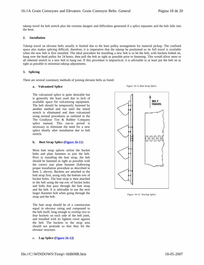
takeup travel for belt stretch plus the extreme dangers and difficulties generated if a splice separates and the belt falls into the boot.
2. Installation
Takeup travel on elevator belts usually is limited due to the boot pulley arrangement for material pickup. The confined space also makes splicing difficult; therefore, it is imperative that the takeup be positioned so its full travel is available when the new belt is first installed. The ideal procedure for installing a new belt is to let the belt, with buckets bolted on, hang over the head pulley for 24 hours, then pull the belt as tight as possible prior to fastening. This would allow most or all inherent stretch in a new belt to hang out. If this procedure is impractical, it is advisable to at least put the belt on as tight as possible to minimize takeup adjustments.
3. Splicing
There are several customary methods of joining elevator belts as listed.
a. Vulcanized Splice
The vulcanized splice is quite desirable but is generally the least used due to lack of available space for vulcanizing equipment. The belt should be temporarily fastened by another method and run until the initial stretch is eliminated and then vulcanized using normal procedures as outlined in the The Goodyear Tire & Rubber Company splice manual. This run-in period is necessary to eliminate the need for a new splice shortly after installation due to belt stretch.
b. Butt Strap Splice (Figure 16-11)
Most butt strap splices utilize the bucket bolts and plate fasteners to join the belt. Prior to installing the butt strap, the belt should be fastened as tight as possible with the correct size plate fastener (following proper installation procedure as described in Item 2, above). Buckets are attached to the butt strap first, using only the bottom row of bucket holes. The butt strap is then attached to the belt using the top row of bucket holes and bolts that pass through the butt strap and the belt. It is advisable to use the next larger diameter bolt when going through the strap and the belt.
The butt strap should be of a construction equal in elevator rating and compound to the belt itself, long enough to overlap two to four buckets on each side of the belt joint, and installed with its lightest cover against the belt. The buckets in the strap area should not protrude so that they hit the elevator structure.
c. Lap Splice (Figure 16-12)
Figure 16-11 Butt Strap Splice
Figure 16-12 Overlap Splice
Página 18 de 2016-1A Grain Conveyors and Elevators: Grain Conveyor Belts: General
18-05-2007file://C:\WINDOWS\Temp\~hhB08B.htm
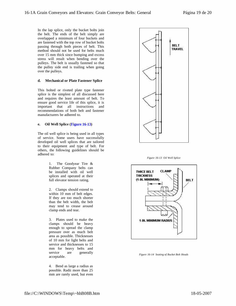
In the lap splice, only the bucket bolts join the belt. The ends of the belt simply are overlapped a minimum of four buckets and are fastened with the top row of bucket bolts passing through both pieces of belt. This method should not be used for belts much over 15 mm thick since bumping and excess stress will result when bending over the pulleys. The belt is usually fastened so that the pulley side end is trailing when going over the pulleys.
d. Mechanical or Plate Fastener Splice
This bolted or riveted plate type fastener splice is the simplest of all discussed here and requires the least amount of belt. To ensure good service life of this splice, it is important that all instructions and recommendations of both belt and fastener manufacturers be adhered to.
e. Oil Well Splice (Figure 16-13)
The oil well splice is being used in all types of service. Some users have successfully developed oil well splices that are tailored to their equipment and type of belt. For others, the following guidelines should be adhered to:
1. The Goodyear Tire & Rubber Company belts can be installed with oil well splices and operated at their full elevator tension rating.
2. Clamps should extend to within 10 mm of belt edges. If they are too much shorter than the belt width, the belt may tend to crease around clamp ends and tear.
3. Plates used to make the clamps should be heavy enough to spread the clamp pressure over as much belt area as possible. Thicknesses of 10 mm for light belts and service and thicknesses to 15 mm for heavy belts and service are generally acceptable.
4. Bend as large a radius as possible. Radii more than 25 mm are rarely used, but even
Figure 16-13 Oil Well Splice
Figure 16-14 Seating of Bucket Bolt Heads
Página 19 de 2016-1A Grain Conveyors and Elevators: Grain Conveyor Belts: General
18-05-2007file://C:\WINDOWS\Temp\~hhB08B.htm
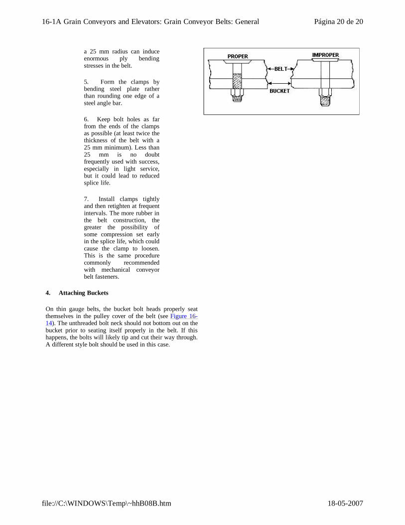
a 25 mm radius can induce enormous ply bending stresses in the belt.
5. Form the clamps by bending steel plate rather than rounding one edge of a steel angle bar.
6. Keep bolt holes as far from the ends of the clamps as possible (at least twice the thickness of the belt with a 25 mm minimum). Less than 25 mm is no doubt frequently used with success, especially in light service, but it could lead to reduced splice life.
7. Install clamps tightly and then retighten at frequent intervals. The more rubber in the belt construction, the greater the possibility of some compression set early in the splice life, which could cause the clamp to loosen. This is the same procedure commonly recommended with mechanical conveyor belt fasteners.
4. Attaching Buckets
On thin gauge belts, the bucket bolt heads properly seat themselves in the pulley cover of the belt (see Figure 16-14). The unthreaded bolt neck should not bottom out on the bucket prior to seating itself properly in the belt. If this happens, the bolts will likely tip and cut their way through. A different style bolt should be used in this case.
Página 20 de 2016-1A Grain Conveyors and Elevators: Grain Conveyor Belts: General
18-05-2007file://C:\WINDOWS\Temp\~hhB08B.htm