HAND TOOLS - NASA HAND TOOLS NOSE CLAMP TOOL Avai\able hose clamp tools either are difficult is use...
29
NASA SP-5908 (03) TECHNOLOGY UTILIZATION HAND TOOLS A COMPILATION NATIONAL AERONAUTICS AND SPACE ADMINISTRATION' https://ntrs.nasa.gov/search.jsp?R=19710014434 2018-06-10T22:21:49+00:00Z
Transcript of HAND TOOLS - NASA HAND TOOLS NOSE CLAMP TOOL Avai\able hose clamp tools either are difficult is use...

NASA SP-5908 (03)
TECHNOLOGY UTILIZATION
HAND TOOLS
A COMPILATION
NATIONAL AERONAUTICS AND SPACE ADMINISTRATION'
https://ntrs.nasa.gov/search.jsp?R=19710014434 2018-06-10T22:21:49+00:00Z
NASA SP-5908 ( 03)
HAND TOOLS
A COMPILATION
TECHNOLOGY UTILIZATION OFFICE 1970 NATIONAL AERONAUTICS AND SPACE ADMINISTRATlON
WaJhiegton, D.C.

NOTICE This document was prepared under the sponsorship of the National Aeronautics and Space Administration. Neither the United States Government nor any person acting on behalf of the United States Government assumes any liability resulting from the use of the information contained in this document, or warrants that such use will be free from privately owmd rights.
For sale by the National Technical Information Service, Springfield, Virginia 22151 -Price $1.00

Foreword
The National Aeronautics and Space Administration has established a Technol- ogy Utilization Program for the dissemination of information on technologi- cal developments which have potential utility outside the aerospace community. By encouraging multiple application of the results of its research and development. NASA earns for the public an increased return on the investment in aero- space research and development programs.
Presented in this compilation are a selection of new hand tools, modifications of existing tools, and techniques developed in the course of NASA research and development projects. The items are presented in two sections: Mechanical Tools and Electrical Tools. Safety is emphasized, together with ease of operations and use in restricted areas or hazardous environments. The discussions are directed primarily toward the technician engaged in assembly or maintenance of mechanical or elecbri- cal equipment.
While it is possible that items similar to some of those included in'this complia- tion have been independently developed by other organizations or personnel, they are all believed to be useful.
Additional technical information on individual tools and techniques can be requested by circling the appropriate number on the Reader's Service Card included in this compilation.
Unless otherwise stated, NASA contemplates no patent action on the technol- ogy described.
We appreciate comment by readers and welcome hearing about the relevance and utility of the information in this compilation.
Ronald J. Philips, Director Technologj~ Utilisatiotl Office Natioual Aerot~autics a t ~ d Space Adt~~itristration
iii
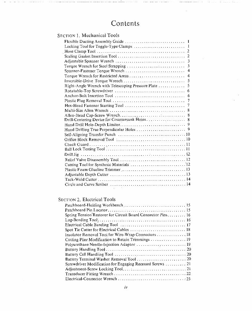
Contents
SECTION 1 . Mechanical Tools Flexible Ducting Assembly Guide . . . . . . . . . . . . . . . . . . . . . . . . . . . . . 1 Locking Tool for Toggle-Type Clamps . . . . . . . . . . . . . . . . . . . . . . . . . 1
. . . . . . . . . . . . . . . . . . . . . . . . . . . . . . . . . . . . . . . . . . . Hose Clamp Tool 2 . . . . . . . . . . . . . . . . . . . . . . . . . . . . . . . . . Sealing Gasket Insertion Tool 2
Adjustable Spanner Wrench . . . . . . . . . . . . . . . . . . . . . . . . . . . . . . . . . . 3 Torque Wrench for Steel Strapping . . . . . . . . . . . . . . . . . . . . . . . . . . . . 3 Spanner-Fastener Torque Wrench . . . . . . . . . . . . . . . . . . . . . . . . . . . . . 4 Torque Wrench for Restricted Areas . . . . . . . . . . . . . . . . . . . . . . . . . . . 4 Invertible-Drive Torque Wrench . . . . . . . . . . . . . . . . . . . . . . . . . . . . . . 5 Right-Angle Wrench with Telescoping Pressure Plate . . . . . . . . . . . . . 5
. . . . . . . . . . . . . . . . . . . . . . . . . . . . . . . . . . Rotatable-Top Screwdriver 6 Anchor-Bolt Insertion Tool . . . . . . . . . . . . . . . . . . . . . . . . . . . . . . . . . . 6 Plastic Plug Removal Tool . . . . . . . . . . . . . . . . . . . . . . . . . . . . . . . . . . . 7 Hex-Head Fastener Starting Tool . . . . . . . . . . . . . . . . . . . . . . . . . . . . . 7
. . . . . . . . . . . . . . . . . . . . . . . . . . . . . . . . . . . . . Multi-Size Allen Wrench 8 . . . . . . . . . . . . . . . . . . . . . . . . . . . . . . . . Allen-Head Cap-Screw Wrench 8
Drill-Centering Device for Countersunk Roles . . . . . . . . . . . . . . . . . . . 8 . . . . . . . . . . . . . . . . . . . . . . . . . . . . . . . . Hand Drill Hole-Depth Limiter 9
Hand Drilling True Perpendicular Holes . . . . . . . . . . . . . . . . . . . . . . . . 9 . . . . . . . . . . . . . . . . . . . . . . . . . . . . . . . . . Self-Aligning Transfer Punch 10
. . . . . . . . . . . . . . . . . . . . . . . . . . . . . . . . . . Orifice Block Removal Tool 10 ChuckCuard . . . . . . . . . . . . . . . . . . . . . . . . . . . . . . . . . . . . . . . . . . . . . . . 11
. . . . . . . . . . . . . . . . . . . . . . . . . . . . . . . . . . . . . . . Ball Lock Testing Tool 11 . . . . . . . . . . . . . . . . . . . . . . . . . . . . . . . . . . . . . . . . . . . . . . . . . . . Drill Jig 112
. . . . . . . . . . . . . . . . . . . . . . . . . . . . . . . . Relief Valve Disassembly Tool 12 . . . . . . . . . . . . . . . . . . . . . . . . . . . Cutting Tool for Synthetic Materials 12
. . . . . . . . . . . . . . . . . . . . . . . . . . . . . . . Plastic Foam Glueline Trimmer 13 . . . . . . . . . . . . . . . . . . . . . . . . . . . . . . . . . . . . . Adjustable Depth Cutter 13
. . . . . . . . . . . . . . . . . . . . . . . . . . . . . . . . . . . . . . . . . . . Tack-Weld Cutter 14 . . . . . . . . . . . . . . . . . . . . . . . . . . . . . . . . . . . . . Circle and Curve Scriber 14
SECTION 2 . Electrical Tools Patchboard-Holding Workbench . . . . . . . . . . . . . . . . . . . . . . . . . . . . . . 15 Patchboard Piq Locator . . . . . . . . . . . . . . . . . . . . . . . . . . . . . . . . . . . . . . 15
. . . . . . . . . Spring Tension Restorer for Circuit Board Connector Pins 16 Lug-BendingTool . . . . . . . . . . . . . . . . . . . . . . . . . . . . . . . . . . . . . . . . . . . 16 Electrical Cable Banding Tool . . . . . . . . . . . . . . . . . . . . . . . . . . . . . . . . 17
. . . . . . . . . . . . . . . . . . . . . . . . . . . Spot Tie Cutter for Electrical Cables 18 . . . . . . . . . . . . . . Insulator Removal Tool for Wire-Wrap Connectors 18
. . . . . . . . . . . . . . . . . Cutting Plier Modification to Retain Trimmings 19 . . . . . . . . . . . . . . . . . . . . . . . . Polyurethane Needle-Injection Adaptor 19
. . . . . . . . . . . . . . . . . . . . . . . . . . . . . . . . . . . . . . . Battery Handling Tool 20 Battery Cell Handling Tool . . . . . . . . . . . . . . . . . . . . . . . . . . . . . . . . . . . 20
. . . . . . . . . . . . . . . . . . . . . . . . Battery Terminal Washer Removal Tool 20 . . . . . . . . . . Screwdriver Modification for Engaging Recessed Screws 21
Adjustment-Screw Locking Tool . . . . . . . . . . . . . . . . . . . . . . . . . . . . . . . 21 . . . . . . . . . . . . . . . . . . . . . . . . . . . . . . . . . . . Transducer Fitting Wrench 22
Electrical-Connector Wrench . . . . . . . . . . . . . . . . . . . . . . . . . . . . . . . . . 23
Section I. Mechanical Tools
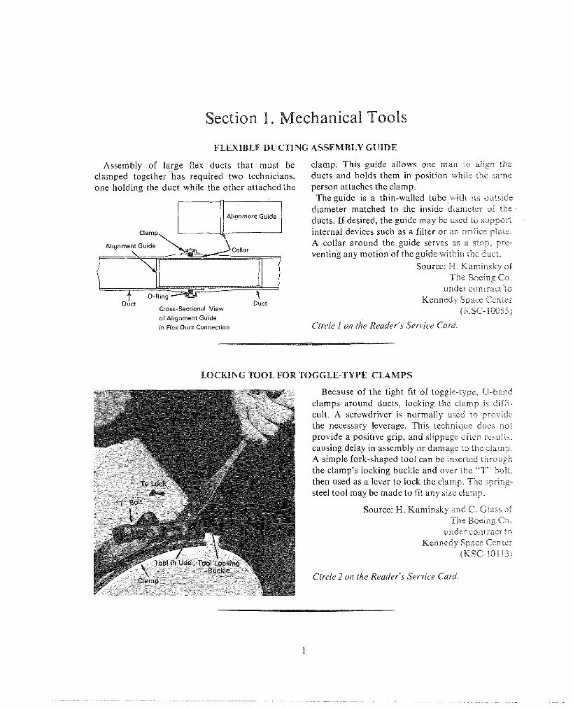
FLEXIBLE DUCTING ASSEMBLY GUIDE
Assembly of large flex ducts that must be clamped together has required two technicians, one holding the duct while the other attached the
1 ) I Alignment Guide I Clamp
\
Cross-Sectional View
of Alignment Guide
in Flex Duct Connection
clamp. This guide allows one man io al~gn the ducts and holds them in position whrie the same person attaches the clamp. The guide is a thin-walled tube wail? nts outside
diameter matched to the inside d~arneter of the ducts. If desired, the guide may be used to support internal devices such as a filter or an ordace piate. A collar around the guide serves as a siop. pre- venting any motion of the guide within the duct.
Source: H. Karnrnsky of The Boeing Co.
under contractto Kennedy Space Center
(KSC- B 0055)
Circle I on the Reader's Service Card
LOCKING TOOL lFOR TOGGLE-TYPE CLAMPS
Because of the tight fit of toggle-type, U-band clamps around ducts, locking the clamp IS diEE1- cult. A screwdriver is normally used to provide the necessary leverage. This technique does not provide a positive grip, and slippage often results, causing delay in assembly or damage to the clamp. A simple fork-shaped tool can be inserted tl-rrough the clamp's locking buckle and over the "T" bolt, then used as a lever to lock the clamp. The spring- steel tool may be made to fit any size clamp.
Source: H. Kaminsky and 63. Glass of The Boeing Co.
under contract to Kennedy Space Cen ier
QKSC-10113)
Circle 2 o~z the Reader's Service Card.

2 HAND TOOLS
NOSE CLAMP TOOL
Avai\able hose clamp tools either are difficult is use In contsned areas, or they do not provide positive control over the hose clamp. This tool provides posltave control over the resistive force of a spnng-type hose clamp, is easy to use, and reduces the tnme required to install or remove the
i-i -7 The loo1 is constructed by modifying a com-
mon pair of pliers. First the external parts of the jaws are sernoved to permit easy operation in
close quarters: then a hole is drilled through each plier jaw. Finally, a chain is attached to one handle and a notch is cut into the other. In use, the ends of the hose clamp are pressed through the holes, the handles are compressed until the clamp has opened to the desired diameter, and the tool is locked by setting a chain link into the notch. The clamp is thus retained in an open position, allow- ing easy manipulation while reducing bo'th the time consumed and the risk of injury.
Source: R. D. Grantham of The Boeing Co.
under contract to Kennedy Space Center
(KSC- 10220)
Circle 3 on the Reader's Service Card.
SEALING GASKET INSERTION TOOL
Cerlaln couplings used extensively in high- bag and used to insert the ring into the coupling pressure gas systems have seal rings which must be hub. After the other hub is in place, the tool is f'i-eq~m"tly handled during installation and main- removed and the coupling clamps are installed.
Spring Steel
teaance. These operations have been performed by hand, resulting in possible injury to fingers, contamination of the system or damage to the expensive, silver-coated rings. Use of a special tool eliminates these problems.
The tool is essentially a modified set of divider calipers, with a semicircular pair of serrated jaws attached to a spring-loaded, screw-type clamp . - . .
similar to that found on many drafting tools. Jaws Source: E. L. Wells and V. C. Jordon of of different radius are required for different sized The Bendix Corp. rlngs. under contract to
In use, the tool is inserted into the plastic bag Kennedy Space Center contain~ng the clean ring and adjusted to hold (KSC- 10038) ;he ring securely. I t is then withdrawn from the Circle4 orr the Reader's Service Card.
M E C H A N I C A L TOOLS 3
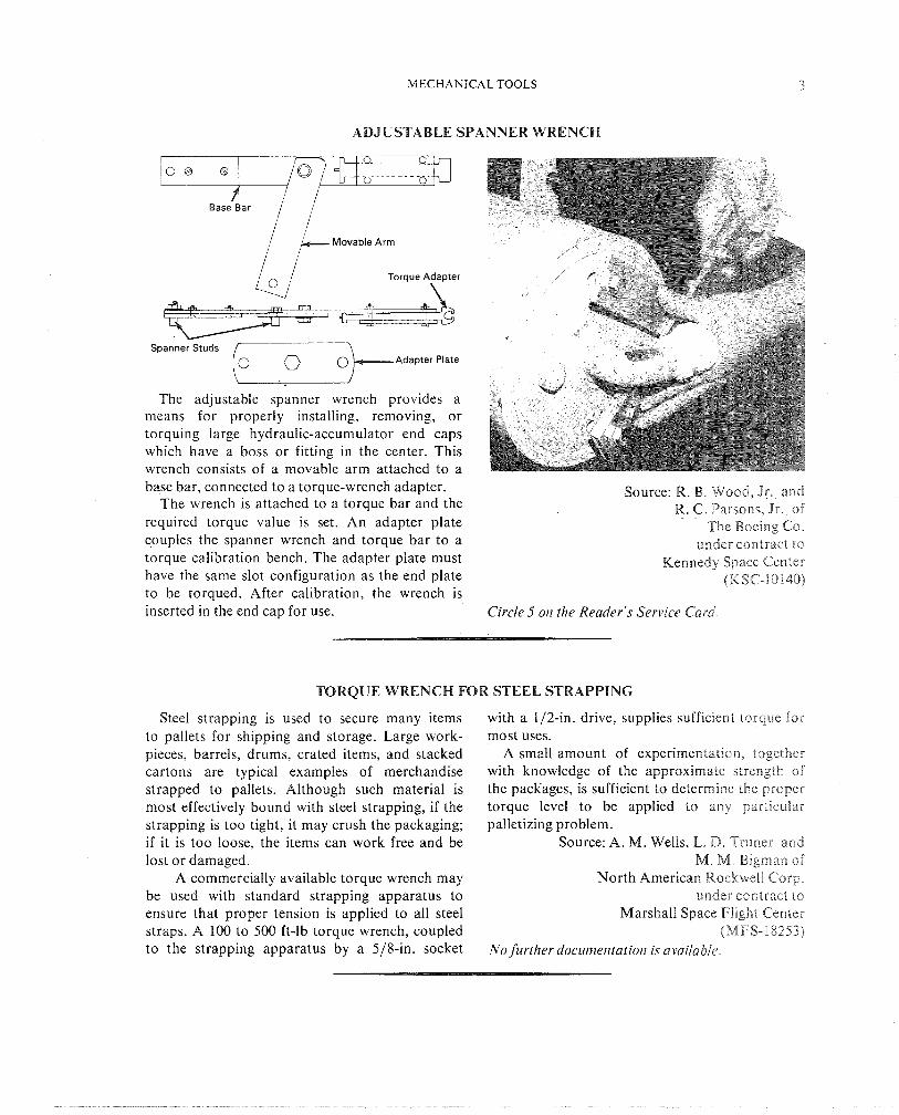
ADJUSTABLE SPANNER WRENCH
/ Movable Arm
Torque Adapter
Spanner Studs ( r O & ~ d o p t e r plate
The adjustable spanner wrench provides a means for properly installing, removing, or torquing large hydraulic-accumulator end caps which have a boss or fitting in the center. This wrench consists of a movable arm attached to a base bar, connected to a torque-wrench adapter. Source: W. B. Wood, Jr . and
The wrench is attached to a torque bar and the R. G. Parsons, Jr . of required torque value is set. An adapter plate The Boeing Co. couples the spanner wrench and torque bar to a under contract to torque calibration bench. The adapter plate must Kennedy Space Center have the same slot configuration as the end plate (K.i-sC-IOl40) to be torqued. After calibration, the wrench is inserted in the end cap for use. Circle 5 on the Reader's Service Card.
TORQUE WRENCH FOR STEEL STRAPPING
Steel strapping is used to secure many items to pallets for shipping and storage. Large work- pieces, barrels, drums, crated items, and stacked cartons are typical examples of merchandise strapped to pallets. Although such material is most effectively bound with steel strapping, if the strapping is too tight, it may crush the packaging; if it is too loose, the items can work free and be lost or damaged.
A commercially available torque wrench may be used with standard strapping apparatus to ensure that proper tension is applied to all steel straps. A 100 to 500 ft-lb torque wrench, coupled to the strapping apparatus by a 518411. socket
with a 112-in. drive, supplies sufficient torque for most uses.
A small amount of experimentation, together with knowledge of the approximate strength of the packages, is sufficient to determine the proper torque level to be applied to any particular palletizing problem.
Source: A. M. Wells, L. D. Truner and M. M. Bigman of
North American Rockwell Corp. under contract to
Marshall Space Flight Center (MFS-1825%)
No further docurneritatiori i s available.
HAND TOOLS
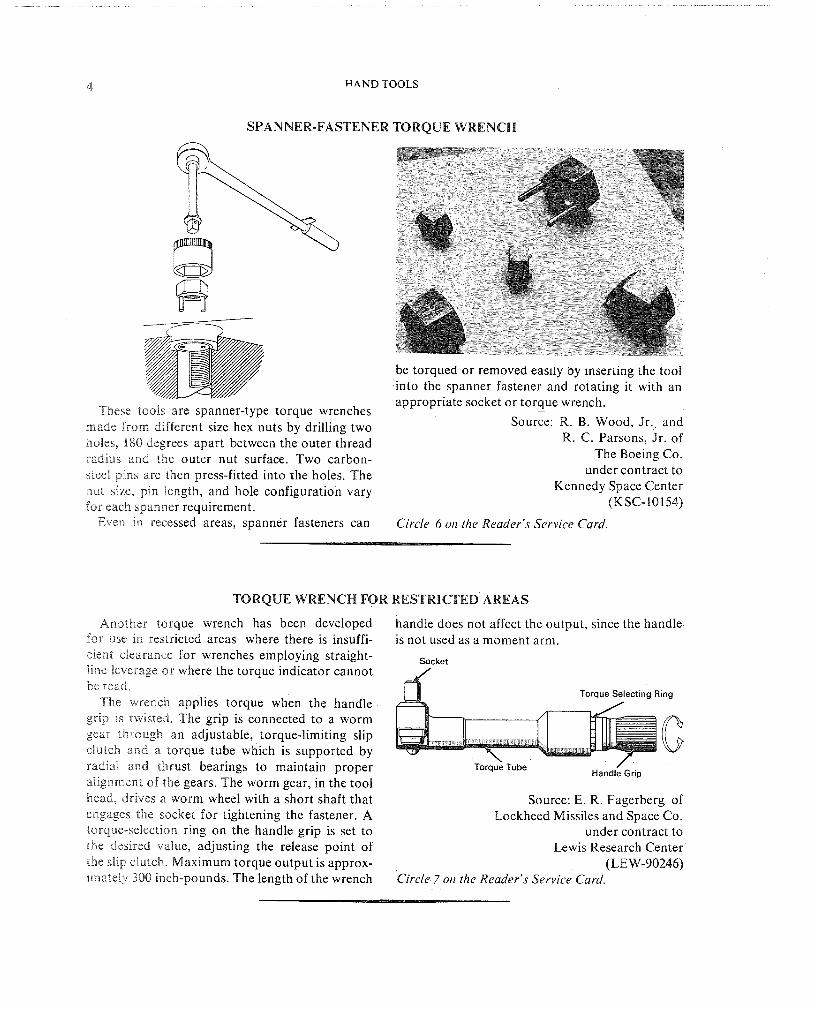
SPANNER-FASTENER TORQUE WRENCH
These tools are spanner-type torque wrenches made from different size hex nuts by drilling two holes, 180 degrees apart between the outer thread radius and the outer nut surface. Two carbon- steel pins are then press-fitted into the holes. The nut size, pin length, and hole configuration vary for each spanner requirement.
Even in recessed areas, spanner fasteners can
be torqued or removed easlly by Inserting the tool into the spanner fastener and rotating it with an appropriate socket or torque wrench.
Source: R. B. Wood, Jr. and R. C. Parsons, Jr. of
The Boeing Co. under contract to
Kennedy Space Center (KSC-10154)
Circle 6 on the Reader's Service Card.
TORQUE WRENCH FOR RESTRICTED AREAS
Another torque wrench has been developed for use 111 restricted areas where there is insuffi- cient clearance for wrenches employing straight- lnne leverage or where the torque indicator cannot be read.
The wrench applies torque when the handle grap ns fwssted. The grip is connected to a worm gear through an adjustable, torque-limiting slip clutch and a torque tube which is supported by radial and thrust bearings to maintain proper alngnment of the gears. The worm gear, in the tool head, drsves a worm wheel with a short shaft that engages the socket for tightening the fastener. A torque-seiectron ring on the handle grip is set to the desired value, adjusting the release point of the shp ciutcch Maximum torque output is approx- imately 300 inch-pounds. The length of the wrench
handle does not affect the output, since the handle is not used as a moment arm.
Torque Selecting Ring
Torq& Tube / Handle Grip
Source: E. R. Fagerberg of Lockheed Missiles and Space Co.
under contract to Lewis Research Center
(LE W-90246) Circle 7 011 the Reader's Service Card.

lMECHANICAL TOOLS 5
INVERTIBLE-DRIVE TORQUE WRENCH
The problem of using ordinary torque wrench- es in another common situation has also been solved in a novel way. When using a conventional torque wrench on bolts which project from the underside of a machine, for example, the indicator cannot be read directly; a mirror must be used. The modified wrench provides a means of easily viewing the torque indicator on the wrench, regardless of the orientation of the part being torqued. The wrench has a drive shaft that can protrude from either side of the wrench head. This allows the socket to be placed on either side of the wrench, keeping the torque indi- cator in view. The shaft has three spring-loaded balls, two of which lock the shaft in position while the third locks into the socket. The wreqch can be converted to accommodate the socket on the reverse side merely by pushing the protruding end of the shaft into the shank.
Spring Loaded Balls
Lower Position
Source: M. DeBarnardo of North American Rockwell Corp.
under contract to Marshall Space Flight Center
(MFS-598) No further documerrtatiorz is availabie.
RIGHT-ANGLE WRENCH WITH TELESCOPING PRESSURE PLATE
,Pressure Plate Handle for Turning Rod
Telescope Section I Cam Wheel to Comnress Sorino
Permit cable to Turn 7 114" Flex Cable
\ 114" Mild Steel Rod
Male Tip (Can be Adapted to Any Size)
Another wrench has been designed to permit easy installation or removal of threaded fasteners in certain types of confined areas. It has a T-shap- ed body constructed from 318-in. I.D. steel tubing. Torque is coupled from a handle at the end of the stem, through a 114-in. steel rod supported on bushings inside the stem, to a 114-in. flexible cable. The cable bends through a right angle, pass- ing through adjacent slots in the stem and one arm of the T, and supplies torque to a male cou- pler. Various attachments may be installed on the
coupler to drive different types of threaded fas- teners.
The opposite arm of the T consists of a heles- coping spring-loaded pressure plate. A steel cable attached to the inner face of the plate runs down the center of the tube, around a pulley, out through the milled slot, and down the stem to a cam attached to the side of the stem When the cam is rotated to the rear, the pressure plate is pulled toward the stem, compressing the spring. After the tool has been inserted and the driver has been seated on the fastener, the cam is released, the spring relaxes, and the pressure plate is forced against the opposite surface of the confined area. The spring pressure prevents the coupler or the driver from disconnecting while torque is appined to the fastener.
Source: R. S. Richardson of The Boeing Co.
under contract to Marshall Space Flight Center
(MFS- 15046) Circle 8 or1 the Reader's Service Card

HAND TOOLS
ROTATABLE-TOP SCREWDRIVER
A screwdriver with a ,rotatable top allow's the user to continue to apply pressure to a screw
- throughout regripping motions, thus reducing the possibility of dropping the screw and allowing the screw to be installed with one hand.
The turntable top, made from polytetrafluo- roethylene (PTFE) or nylon material, is held in place by a screw. Two washers provide bearing surfaces for smoother turning.
Source: C. H. Keedy of North American Rockwell Corp.
under contract to Marshall Space Flight Center
(MFS-14175) Washer No further documerrtatiorl is available.
ANCHOR-BOLT INSERTION TOOL
Handle Dr~ve
Holder
Before Hammer Strike After Hammer Strike
This tool is used to expand the lead shields oq anchor bolts without regard to hole depth. It is partacularly useful when installing anchors in concrete block walls where it is difficult to set the sh~e ld properly without damaging the wall.
The tool is made of a base plate, an anchor stud, and a sliding striking head. The anchor to be lnctailed is screwed onto the anchor stud, insert-
ed into the pre-drilled hole and set with a single blow on the striking head.
Source: R. Hosler of Trans World Airlines, Inc.
under contract to Kennedy Space Center
(KSC-10253) No further documer~tatio~~ is available.
MECHANICAL TOOLS
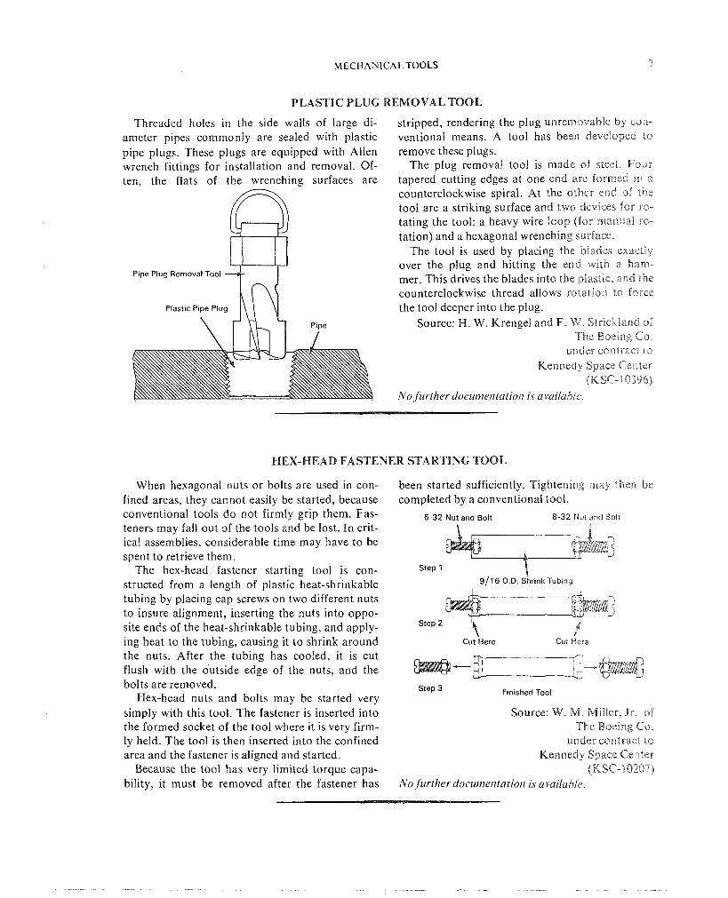
PLASTIC PLUG REMOVAL TOOL
Threaded holes in the side walls of large di- ameter pipes commonly are sealed with plastic pipe plugs. These plugs are equipped with Allen wrench fittings for installation and removal. Of- ten, the flats of the wrenching surfaces are
Pipe Plug Removal Tool I
Plastic Pipe plug hm
stripped, rendering the plug unremovable by con- ventional means. A tool has been developed to remove these plugs.
The plug removal tool is made of steel. Four tapered cutting edges at one end are formed an a counterclockwise spiral. At the other en~d of the tool are a striking surface and two devnces for ro- tating the tool: a heavy wire loop (For manual ro- tation) and a hexagonal wrenching surface.
The tool is used by placing the blades exactly over the plug and hitting the end with a ham- mer. This drives the blades into the plastic, and the counterclockwise thread allows rotation to force the tool deeper into the plug.
Source: H. W. Krengel and F. W. Strlckland of The Boelng Co
under contract to Kennedy Space Centen
(MSC- 10396) No Jurther docur?ierltatiorr is avvailabi~
HEX-HEAD FASTENER STARTING TOOL
When hexagonal nuts or bolts are used in con- fined areas, they cannot easily be started, because conventional tools do not firmly grip them. Fas- teners may fall out of the tools and be lost. In crit- ical assemblies, considerable time may have to be spent to retrieve them.
The hex-head fastener starting tool is con- structed from a length of plastic heat-shrinkable tubing by placing cap screws on two different nuts to insure alignment, inserting the nuts into oppo- site ends of the heat-shrinkable tubing, and apply- ing heat to the tubing, causing it to shrink around the nuts. After the tubing has cooled, it is cut flush with the outside edge of the nuts, and the bolts are removed.
Hex-head nuts and bolts may be started very simply with this tool. The fastener is inserted into the formed socket of the tool where it is very firm- ly held. The tool is then inserted into the confined area and the fastener is aligned and started.
Because the tool has very limited torque capa- bility, it must be removed after the fastener has
been started sufficiently. Tightening may theen be completed by a conventional tool.
6-32 Nut and Bolt 8-32 N u t and Boil
Step 1
911 6 O.D. Shrink Tubing
Step 2
Cut Here f
Cut Here
Step 3 Finished Tool
Source: W. M. Miller, Js. of The Boeirag Cs.
under contract to Kennedy Space Center
(KSC- 10287) No further ~iocw?~eritatior~ is available.
8 HAND TOOLS
MULTI-SIZE ALLEN WRENCH
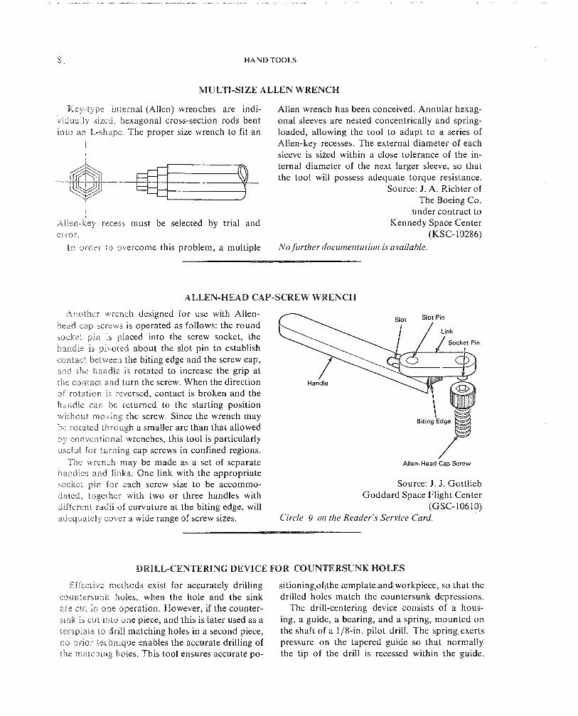
Key-type internal (Allen) wrenches are indi- vidually sized, hexagonal cross-section rods bent lnho an L-shape. The proper size wrench to fit an
I 1
I
~ l l e n - i e ~ recess must be selected by trial and error.
Allen wrench has been conceived. Annular hexag- onal sleeves are nested concentrically and spring- loaded, allowing the tool to adapt to a series of Allen-key recesses. The external diameter of each sleeve is sized within a close tolerance of the in- ternal diameter of the next larger sleeve, so that the tool will possess adequate torque resistance.
Source: J. A. Richter of The Boeing Co.
under contract to Kennedy Space Center
(KSC- 10286) I n order ro overcome this problem, a multiple No firrtherdocumetltatiotr is available
ALLEN-HEAD CAP-SCREW WRENCH
Anether wrench deslgned for use with Allen- nead cap screws 1s operated as follows: the round socket pen IS placed into the screw socket, the handle rs pivoted about the slot pin to establish
n
contact between the biting edge and the screw cap, ,inid the handle 1s rotated to increase the grip at the csntdct and turn the screw. When the direction sat roiataon IS reversed, contact is broken and the handle can "o returned to the starting position ~vlihout movlng the screw. Since the wrench may be rotdted through a smaller arc than that allowed by conventional wrenches, this tool is particularly uaefesP icss turning cap screws in confined regions.
The wrench may be made as a set of separate ~ i ~ e n - H e a d Cap Screw
handles and lanks. One link with the appropriate socket pan for each screw slze to be accommo- Source: J. J. Gottlieb dated, tcsgeiher with two or three handles with Goddard Space Flight Center differenl. radii of curvature at the biting edge, will (GSC-10610) adequately cover a wide range of screw sizes. Circle 9 on the Reader's Servzce Card.
DRILL-CENTERING DEVICE FOR COUNTERSUNK HOLES
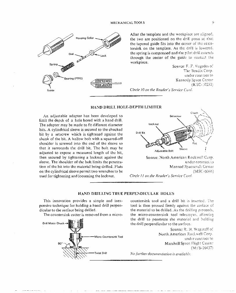
Eflzctnve methods exist for accurately drilling sitioningloflthe iemplate andlworkpiece, so that the counterbunk holes, when the hole and the sink drilled holes match the countersunk depressions. are cay& ~n one operation. However, if the counter- The drill-centering device consists of a hous- sank as cut into one piece, and this is later used as a ing, a guide, a bearing, and a spring, mounted on template to drail matching holes in a second piece, the shaft of a 118-in. pilot drill. The spring exerts no prior technique enables the accurate drilling of pressure on the tapered guide so that normally the rnatch~ng holes. This tool ensures accurate po- the tip of the drill is recessed within the guide.
MECHANICAL TOOLS 9
After the template and the workplece are ali~gned. the two are positioned on the dr~ l l press so that the tapered guide fits into the center of the coun- tersink on the template. As the drill is lowered,
f: ,I , the spring is compressed and the palot drill extends through the center of the guide to contact the
Spring
h
workpiece. source: F. Z . Vsgedes of
The Bendix COT. qKBearing ' P T W Kennedy under Space contract Center to (KSC-10232)
Gu~de Circle 10 or! the Reader's Service Card.
HAND DRILL MOLE-DEPTH LIMITER
An adjustable adapter has been developed to limit the depth of a hole bored with a hand drill. The adapter may be made to fit different diameter bits. A cylindrical sleeve is secured to the chucked
D r ~ l bit by a setscrew which is tightened against the shank of the bit. A hollow bolt with a squared-off shoulder is screwed into the end of the sleeve so that it surrounds the drill bit. The bolt may be adjusted to expose a measured length of the bit, then secured by tightening a locknut against the Source: North American Rockwe]! Corp. sleeve. The shoulder of the bolt limits the penetra- under contract to tion of the bit into the material being drilled. Flats Manned Spacecraft Center on the cylindrical sleeve permit two wrenches to be (MSC-0346) used for tightening and loosening the locknut. Circle I I oil the Reader's Service Carof
HAND DRILLING TRUE PERPENDICULAR HOLES
This innovation provides a simple and inex- countersink tool and a drill bit is inserted. The pensive technique for holding a hand drill perpen- tool is then pressed firmly against the surface of dicular to the surface being drilled. the material to be drilled. As the drilling proceeds,
The countersink cutter is removed from a micro- the micro-countersink tool telescopes, a8Eowing the drill to penetrate the material and holding
Drill Motor chuck the drill perpendicular to the surface.
Source: R. H. Wagstaff of North American Rockwell Corp.
Micro-Countersink Tool under contract to
Marshall Space Fligl-ri Center (MFFS- 15437)
Twist Drill No.furrher docurlzeirtatiorr is aavailahir.

10 H A N D TOOLS
SELF-ALIGNING TRANSFER PUNCH
Commerically available transfer punches have held, there is no assurance that the axis of the tapered noses to locate the center of a hole being punch is normal to the plate containing the refer- transferred. However, when the punch is hand ence hole.
This innovation automatically holds the trans- fer punch perpendicular to the surface of the reference plate, as well as central with respect to the locating hole. The outer gripping body of a spring-loaded, cone-nosed transfer punch has been bored so that it can be brought down flush with the surface of the reference plate. The cone portion of the punch locates the center of the reference
Compression Spring hole. With the punch so located, it can be struck with a hammer, accurately transferring the true
Vertical Alignment hole location to the workpiece. and Holding Body Source: H. Greenstreet of
This Suriace Aligns
Punch in Vertical North American Rockwell Corp.
Atrinude under contract to Marshall Space Flight Center
Location of Hole (MFS- 14276)
Being Transferred NO Jirrther doc~rt)~etltntiot~ is availablr.
ORIFICE BLOCK REMOVAL TOOL
I n servicing solenoid valves, it has been found that orifice blocks are frequently frozen in the valve. To remove these blocks, a drive punch was inserted into the valve input or outlei port, and the orifice block was jarred loose by hammering on the punch. Consequently, many orifice blocks and valves have been damaged when the punch slipped.
The orifice block removal tool, which solves this problem, consists of a frame, a threaded stud with a pin holder welded to one end and a handle on the other end, a nut and washer, and a pin that is sounded on each end. The frame rests on the solenoid valve body and the stud is lowered into the orifice block until the pin holder is in line with a port. The pin is inserted through the port and then the nut on the frame is tightened. Because the pin has rounded ends and fits loosely in the pin holder, it will center itself, preventing damage to the vaive during extraction. The nut is tightened un t i l the orifice block is freed.
Orifice Block
Source: J . T. Deitz of The Boeing Co.
under contract to Kennedy Space Center
(KSC-10134) Circle 12 0 1 1 the Reader's Srrvicr Carcl.

MECHANICAL TOOLS 1 :
CHUCK GUARD
The device is a stationary guard for the ro- tating chuck of a power hand drill. When drilling through a densely packed panel, the guard pro- tects nearby components and the panel surface from damage by inadvertent contact with the chuck.
The guard consists of a sleeve of semi-rigid plastic material, such as polyethylene, mounted on the body of the drill. The illustratior. shows a guard for an air-driven drill. An internally thread- ed adapter ring replaces the normal locking ring, through which the chuck drive-shaft emerges, on the threaded stub in the drill handle. The adapter ring has a shoulder which surrounds the chuck and over which the protective guard is slipped. The diameter of the outer end of the plastic guard, through which the drill protrudes, is reduced. As a precaution, all edges of the holding fixture are rounded.
Pneumatic Driver .Key Access Hole
/ 1 Chuck Guard Adapter Ring
Replaces Locking Ring
Source: W. W. Voorhest and E. C. Fhitterer of Grumman Aircraft Engineering Corp.
under contract to Manned Spacecraft Center
(MSSC-12252)
BALL LOCK TESTING TOOL
To test-activate ball lock holding devices, it has been necessary to use common hand tools, which often damaged the mechanism.
A simple and inexpensive tool has been made to test-activate and deactivate a ball lock holding device conveniently, without damage to the mech- anism.
Force Application
Plunger
re
Cylinder
Reset
The end of the tool used to activate the: mech- anism is a solid rod with a rounded end. Thc rod diameter is slightly smaller than the separatton between the balls in the activated psos~t~oi-e. The surface at the end of the rod closely approximates the curvature of the plunger. The o ~ h e r end of the tool is a hollow cylinder with an outer drameter slightly smaller than that of the sleeve, ar, lnraer diameter large enough to pass the mechanrsm cylinder, and a depth that will allow the full strekc of the device.
In use, the solid end of the tool ns placed 11310
the mechanism. An inward push trips the device so that the balls move to their innermost, Pocked position. To reset the device, the ohber end of the tool is placed in alignment with the sleeve and pushed, resetting the lock.
Source: C. J. Benedrct cf %he Boeing CCP.
under contract to Kennedy Space Center
(K SC- 10360)
No further doc~ct~zentation is availabie

% 2 HAND TOOLS
DRILL J I G
The drril jig IS a Nu-Vise or similar clamp with guide arrangement is secured to the clamp by two the standard clamping posts removed and replaced locknuts. by a drill bushing and guide. The bushing and The prior method used from one to four clamps
to hold the drill bushing in place while drilling. Clamp Dr~ll Gurcle Since the bushing did not have a guide, a second
and Drill Bushing \ operator was required to sight-in the drill.
Source: J. H. Long and H. T. Greene of North ~ m k r i c a n Rockwell Corp.
under contract to Marshall Space Flight Center
(M FS- 12605)
I I Circle 13 on the Reader's Service Card.
RELIEF VALVE DISASSEMBLY TOOL
eal Separating Seal~ng Surfaces evlce
(Shown Separated)
Each time a relief valve is disassembled con- ventionally, the soft metal seat of the seal is damaged by the rotation necessary to remove the piston assembly.
A tool has been designed that may be screwed into the valve output port to separate the sealing surfaces before disassembly. When the piston assembly is unscrewed, the sealing surfaces are not in contact and cannot be scored. By leaving this device in place, the reassembly can also be made without seal contact.
Source: P. E. Weaver of The Boeing Co.
under contract to Kennedy Space Center
(KSC- 10098)
Circle 14 on the Reader's Service Card.
CUTTING TOOL FOR SYNTHETIC ,MATERIALS
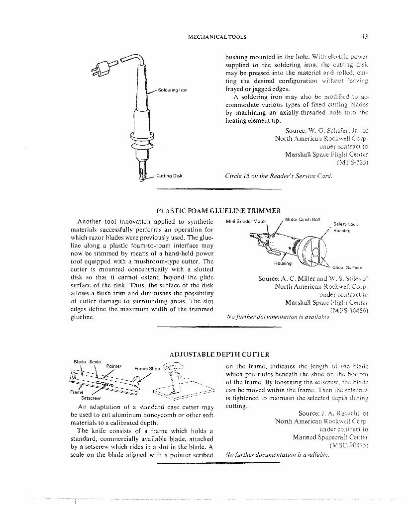
FOB working with synthetic materials, several terials economically and cleanly, a pencil-type specialized tools have been developed to replace soldering iron has been modified to accommodate common tools, doing the same job better or more a cutting disk. efficiently. The first replaces an ordinary knife, An axial slot is machined in the soldering iron eeiher cold or externally and intermittently tip and a hole is drilled through both sides of the heated. slot. A stainless steel rotary cutting disk is attach- TO cut large sheets of certain synthetic ma- ed to a shaft that rotates in a rapid heat-transfer
MECHANICAL TOOLS 13
bushing mounted in the hole. With clectrac power supplied to the soldering iron, the certtlnig dask may be pressed into the material and rolled, cut- ting the desired configuration withoul leaveng frayed or jagged edges.
A soldering iron may also be rnodlfied to ac- commodate various types of fixed c-iiittlrig blades by machining an axially-threaded hole anto tht: heating element tip.
Source: W. 6. Schafer, J r of North American Rockwell Corp.
under cor-ntract to Marshall Space FC~ght Center
bMFS-7258
Circle 15 011 the Reader's Service Card.
PLASTIC FOAM GLUELINE TRIMMER
Another tool innovation applied to synthetic M ~ n l Gr~nder Motor Motor C~nch Boir Sadery Lock
materials successfully performs an operation for Pious~ng
which razor blades were previously used. The glue- line along a plastic foam-to-foam interface may now be trimmed by means of a hand-held power tool equipped with a mushroom-type cutter. The cutter is mounted concentrically with a slotted GIlde Surface
disk so that it cannot extend beyond the glide Source: A. C. Miller and W. S. Stiles of surface of the disk. Thus, the surface of the disk North American Rockwe%l Corp. allows a flush trim and diminishes the possibility under contract to of cutter damage to surrounding areas. The slot Marshall Space Flight Center edges define the maximum width of the trimmed (MFS-16486) glueline. No Jirrther docunzelltatio~l is availabie
ADJUSTABLE DEPTH CUTTER Blade Scale
on the frame, indicates the length of the blade which protrudes beneath the shoe on the bottom of the frame. By loosening the setscrew, the blade
\
can be moved within the frame. Then the setscrew "xe/5
Setscrew is tightened to maintain the selected depth durrng An adaptation of a standard case cutter may cutting.
be used to cut aluminum honeycomb or other soft Source: J. A. Rauschl of materials to a calibrated depth. North American RockweEB Corp.
The knife consists of a frame which holds a under contract to
standard, commercially available blade, attached Manned Spacecraft Center
by a setscrew which rides in a slot in the blade. A (MSC-90475) scale on the blade aligned with a pointer scribed No furtherdocutne~rtariorl isavailablr.

14 HAND TOOLS
TACK-WELD CUTTER
This tool is designed to cut tack welds for Previously, cutting was done with a saw blade or which the offset or the gap between the welded a rivet gun and chisel, which left the weld area pasts exceeds the weld specification tolerances. dirty. This innovation leaves the area clean and
ready for retacking. The cutter, a 1 9/16-in. diameter wheel, is
mounted on the weld skate (or saw) track and
'I aligned with the center of the tack to be cut. The 1 0 cutting depth is adjusted as the cutter is run across k the tack, until the tack is broken.
Source: Z. Y. Jaime of North American Rockwell Corp.
under contract to Marshall Space Flight Center
(M FS- 16440) 1 911 6" Dla Wheel NO j~irther docul??entatio/~ h available.
CIRCLE AND CURVE SCRIBER
This device IS designed for scribing circles or of larger or smaller radius, respectively. Scribing arcs concentric with a machined circle or arc. The is done by moving the locating fixture along the cilrcle scrzber consists of a long bolt with a stylus machined curve, keeping both dowel pins in con- attached to one end, threaded through a locating tact with the curve. Circles may be easily scribed frxt~nre so that the bolt adjustment determines the in this manner on the faces of large flanges, such rad~us of the circle to be scribed. as those involving heavy-process or transfer piping
The Locat~ng fixture is a block of metal with and storage or reactors vessels, without resorting f3,1t, pdrallel upper and lower surfaces. It contains to lengthy procedures or complex apparatus. a threaded hole parallel to the upper surface, Source: J. S. Reti of through which the bolt passes, and two pairs of North American Rockwell Corp. holes bored prependicularly through the surfaces, under contract to to ht a pair of dowel pins. The pins may be placed Marshall Space Flight Center sn either the outer or inner pair of holes to adapt (MFS-185 18) the locator for scribing around machined curves No j urther docunle~ltatio/~ is availnble.
Section 2. Electrical Tools
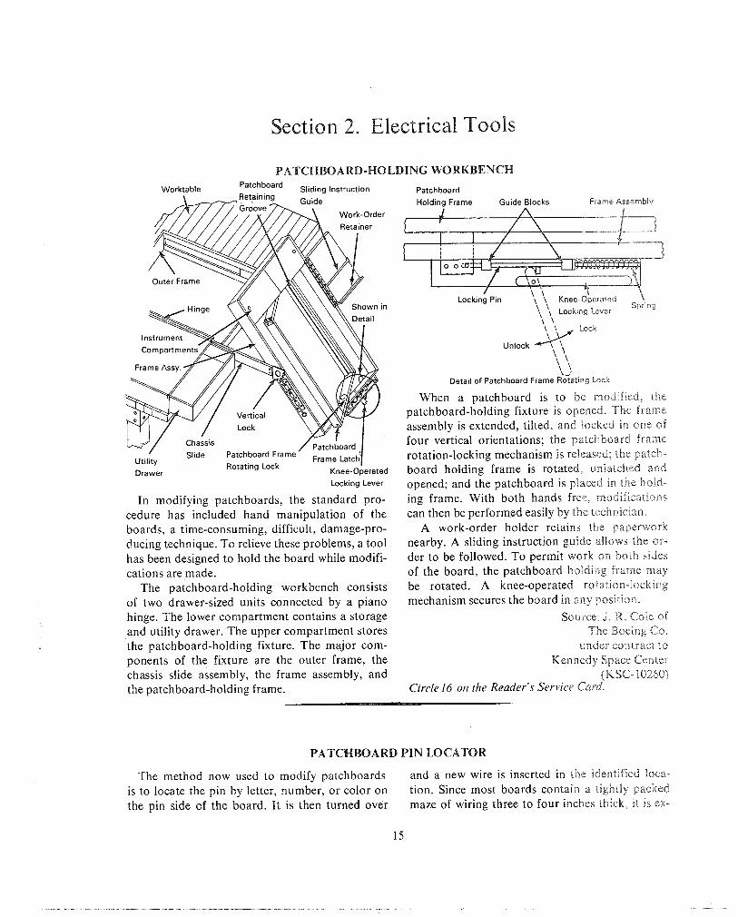
PATCHBOARD-HOLDING WORKBENCH Worktable Patchboard Sliding Instruction Patchboard
Work-Order
Detail of Patchboard Frame Rotating Lock
When a patchboard is to be modified, the patchboard-holding fixture is opened. The frame assembly is extended, tilted, and locked En one of four vertical orientations; the patchboard frame
Slide Patchboard Frame rotation-locking mechanism is released; the patch- Rotating Lock
Drawer nee-operated board holding frame is rotated, unlatched and Locking Lever opened; and the patchboard is placed in the 11old-
In modifying patchboards, the standard pro- ing frame. With both hands free, modificatioi~s cedure has included hand manipulation of the can then be performed easily by the technician. boards, a time-consuming, difficult, damage-pro- A work-order holder retains the paperwork ducing technique. To relieve these problems, a tool nearby. A sliding instruction guide allows the or- has been designed to hold the board while modifi- der to be followed. To permit work 011 both sides cations are made. of the board, the patchboard holding lrarne may
The patchboard-holding workbench consists be rotated. A knee-operated rotation-locking of two drawer-sized units connected by a piano mechanism secures the board in any position. hinge. The lower compartment contains a storage Source: J . R. Cole of and utility drawer. The upper compartment stores The Boeing Co. the patchboard-holding fixture. The major com- under contract to ponents of the fixture are the outer frame, the Kennedy Space Center chassis slide assembly, the frame assembly, and (KSC- 10260) the patchboard-holding frame. Circle 16 on the Reader's Service Card.
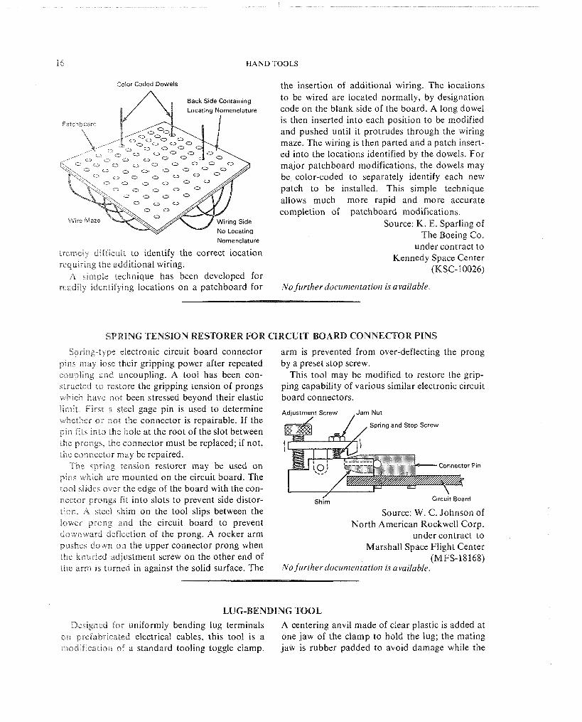
PATCHBOARD PIN LOCATOR
The method now used to modify patchboards and a new wire is inserted in the identified ioca- is to locate the pin by letter, number, or color on tion. Since most boards contain a tightly packed the pin side of the board. It is then turned over maze of wiring three to four inches thick, it is ex-
HAND TOOLS
Conor Coded Dowels the insertion of additional wiring. The locations to be wired are located normally, by designation
re code on the blank side of the board. A long dowel is then inserted into each position to be modified and pushed until it protrudes through the wiring
0 0 0 maze. The wiring is then parted and a patch insert- ed into the locations identified by the dowels. For major patchboard modifications, the dowels may be color-coded to separately identify each new patch to be installed. This simple technique allows much more rapid and more accurate completion of patchboard modifications.
Source: K. E. Sparling of
Nomenclature The Boeing Co.
under contract to tremeiy difficult to identify the correct location Kennedy Space Center requiring the additional wiring. (KSC- 10026) A simple technique has been developed for
readily identifying locations on a patchboard for NoJirr therdoc~rme~~tat io/~ isavailable.
SPRING TENSION RESTORER FOR CIRCUIT BOARD CONNECTOR P I N S
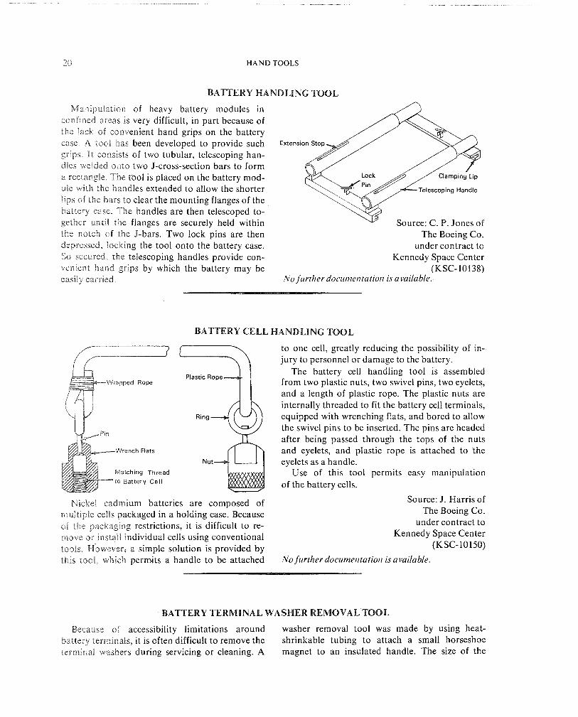
Sprang-type electronic circuit board connector pins may lose their gripping power after repeated coupllng and uncoupling. A tool has been con- structed to restore the gripping tension of prongs which have not been stressed beyond their elastic lirnlt Fsrsc a steel gage pin is used to determine whether or not the connector is repairable. If the pin fits into the hole at the root of the slot between the prongs, the connector must be replaced; if not, the connector may be repaired.
The spring tension restorer may be used on p ~ n s whscb are mounted on the circuit board. The tool slides over the edge of the board with the con-
arm is prevented from over-deflecting the prong by a preset stop screw.
This tool may be modified to restore the grip- ping capability of various similar electronic circuit board connectors.
Adiustment Screw Jam Nut
Spring and Stop Screw
nector prongs fit into slots to prevent side distor- shtm ~ ~ r c u i t Board
tion. A steel shim on the tool slips between the Source: W. C. Johnson of lower prong and the circuit board to prevent North American Rockwell Corp. downward deflection of the prong. A rocker arm under contract to pushes down on the upper connector prong when Marshall Space Flight Center the knurled adjustment screw on the other end of (MFS-18168) the arm is turned in against the solid surface. The NO firrtherdocunie~~tatiot~ isavailable.
LUG-BENDING T O O L
Designed for uniformly bending lug terminals A centering anvil made of clear plastic is added at on prefabricated electrical cables, this tool is a one jaw of the clamp to hold the lug; the mating modification of a standard tooling toggle clamp. jaw is rubber padded to avoid damage while the

ELECTRICAL TOOLS
lug is securely held. Two forming blocks, also of plastic, are attached to the clamp. One is rigidly mounted; its position determines the angle to which the lug will be bent. The other, grooved to accommodate the cable, is pressed down toward the fixed block while the lug is clamp held, thereby forming the predetermined angle.
Previously, lug bending in the field was done either manually or with two pairs of pliers. Hand
bending did not produce a flat terminal surface while use of pliers often damaged the surface. Neither method yielded accurate bend angles.
Source: E. J. Czsey of North American Rockwell Cosp.
under contract. to Manned Spacecraft Center
(MSC-15515) Circle 17 012 the Reader's Service C a d
ELECTRICAL CABLE BANDING TOOL
Manufacturing specifications often require is inserted on one side of the wire bundle, the tool that electric wire bundles and harnesses be collec- is passed behind the bundle from the other side,
tively wrapped with non-metallic straps. This can to engage the strap in the slot. With a slight twist
be difficult to accomplish in confined areas. One of the tool, the strap is held in the slot while the
e tool is withdrawn, completing the operation. Source: R. L. Durham of
The Boeing Co. under contract to
type of standard technician's soldering aid may be Kennedy Space Center
used to overcome such problems. It consists of a (KSC-10139)
rod, bent and slotted at each end. After the strap Circle 18 on the Reader's Service Card.

H A N D TOOLS
SPOT TIE CUTTER FOR ELECTRICAL CABLES
The spot tre cutter is a pair of diagonal cutting pliers, modified by attaching a thin guard plate to the back of each blade. This allows removal of spot tnes from cable assemblies without damage to the cable insulation. Previously, cutter tools were used with a protective finger which had to be rnserted, often with great difficulty, between tie and cable. The tool equipped with guard plates, on the other hand, is easy to use as a spot tie cut- ter, and furthermore, the plates do not interfere with normal cutter uses and reduce the hazard of accidental injury. Source: L. P. David of
As a11 additional modification, the cutter can North American Rockwell Corp be made with a notch in the blades to prevent under contract tc complete cutting of the tie. Manual removal of the Manned Spacecraft Center tie avoids dropping it inside critical assembly (MSC-15590) areas. Circle 19 or! the Reader's Service Card.
INSULATOR REMOVAL TOOL FOR WIRE-,WRAP CONNECTORS
Alligator Clip
Retain only Shaded Portion
I
Bend Here after Cutting
insulator
\ Handle Hole to Fit Insulator
When electronic equipment with wire-wrap connectors is modified, it is difficult to remove or instail the plastic insulators which prevent short circuits between the pins. The only common tool which can manipulate these insulators easily is a pair of needle-nose pliers. If the pliers slip during the process, the jaws mar the surface of the insula- tor. Also, the pressure applied to grip an insulator oftel? cracks i" necessitating replacement. A tool has been developed that easily removes and in- stalls the plastic insulators. With this tool, wire
connection time is greatly reduced and damage to the insulators is eliminated.
The insulator removal tool is constructed from a test-probe handle, a modified alligator clip, and a length of brass rod. To operate, the retaining clip is depresses, the tool is slipped over the insulator, the retaining clip is released, and the insulator is removed by pulling the tool along the terminal axis of the connector pin. The tool re- moves the insulator by applying pressure from below, thus preventing damage to the insulator.

ELECTRICAL TOOLS 19
The tool retains the insulator after removal, pre- Source: W. M. Miller, J r . cl venting its loss. The insulator is easily reinstalled Tite Boelng Co by reversing the above procedure. This tool also under contract to positions ail insulators at the same depth on the Kennedy Space Center connector pins, assuring uniform separation. (K SC- 10206)
Circle 20 oil the Reader's Service Cord
CUTTING PLIER MODIFICATlON TO RETAIN TRIMMINGS
When a wlre 1s trlmrned with cuttang pliers,
the free end is often propelled from the piaerc. causing a safety hazard to nearby personnel and d mechanical hazard to nearby equjpment Paler\ can be simply modified to retaln the trnmrnlng\ by filling the cutting depression wteh a re>ilreiat rubber material.
Source. R. B Wood, J r OF The Boeing Co
under contract to Kennedy Spdce Cctaler
QKSC-FOI 10)
Tr~mmed W ~ r e Circle 21 011 the reader'^ Servrce card
POLYURETHANE NEEDLE-INJECTION ADAPTOR
Polyurethane potting compound is used ex- tensively to protect electrical cable connectors. Air pockets or voids which are frequently left by the molding process represent potential sources of failure. This adaptor provides a means for elimi- nating this problem by injecting polyurethane compound into the voids. The adaptor fits a stand- ard compound tube and gun assembly.
Normal procedure has been to cut back the polyurethane and repeat the entire molding pro- cess. This method is costly in time and material. The adaptor eliminates most of the cutting and reworking.
The adaptor can be made in a variety of styles and materials, chosen to fit the particular applica- tion. Stainless steel has been used in this design, to give corrosion resistance. The adaptor may be easily machined on a lathe; the needle can be braz-
ed onto the fitting. Knurling facilitates hand tight- ening onto the plastic compound tube.
Knurled Stainless Steel
1
Hypodermtc Needle I Threaded Fit Tube
Source W E K ~ r r df
The Bendnx Corp under contr<tct to
Kennedy Space Center gICSc-10&24)
Circle 22 on the Reader's Service Card.
20 HAND TOOLS
BATTERY HANDLING TOOL
Man~ipulation of heavy battery modules in confined areas is very difficult, in part because of the Pack sf convenient hand grips on the battery case. A tool has been developed to provide such Extension Stop
grips. I t consists of two tubular, telescoping han- dles welded onto two J-cross-section bars to form a rectangle. The t ~ o l is placed on the battery mod- u;e with the handles extended to allow the shorter Iescoping Handle
lips of the bars to clear the mounting flanges of the battery case. The handles are then telescoped to- gether until the flanges are securely held within Source: C. P. Jones of the notch of the J-bars. Two lock pins are then The Boeing Co. depressed, Locking the tool onto the battery case. under contract to So secured, the telescoping handles provide con- Kennedy Space Center venient hand grips by which the battery may be (KSC-10138) easily carried. No Jirrther doc~rnle~itatio/i is available.
BATTERY CELL HANDLING TOOL
Wrench Flats
Match~ng Thread to Battery Cell
Nickel cadmium batteries are composed of fisultiple cells packaged in a holding case. Because of the packaging restrictions, it is difficult to re- move or install individual cells using cdnventional tools. ~ b w e v e r ~ a simple solution is provided by this tool, which permits a handle to be attached
to one cell, greatly reducing the possibility of in- jury to personnel or damage to the battery.
The battery cell handling tool is assembled from two plastic nuts, two swivel pins, two eyelets, and a length of plastic rope. The plastic nuts are internally threaded to fit the battery cell terminals, equipped with wrenching flats, and bored to allow the swivel pins to be inserted. The pins are headed after being passed through the tops of the nuts and eyelets, and plastic rope is attached to the eyelets as a handle.
Use of this tool permits easy manipulation of the battery cells.
Source: J. Harris of The Boeing Co.
under contract to Kennedy Space Center
(KSC-10150)
No further documel~tation is available.
BATTERY TERMINAL WASHER REMOVAL TOOL
Because of accessibility limitations around washer removal tool was made by using heat- battery terminals, it is often difficult to remove the shrinkable tubing to attach a small horseshoe terminal washers during servicing or cleaning. A magnet to an insulated handle. The size of the
ELECTRICAL TOOLS 2 B
magnet and the handle vary with the requlaernen?. However, a simple bar magnet is inadequate, since it does not provide the required symnaetricaB force to remove the washer. Since the tool is completely covered with non-conductive material, it presents no electrical safety problem if accidentally drop- ped across two battery terminals.
Source: L. W. Rabb of The Boeing Co.
under contract to Kennedy Space Center
(KSC-10871 j
Circle 23 on the Reader's Service Card
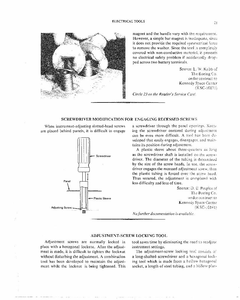
SCREWDRIVER MODIFICATION FOR ENGAGING RECESSED SCREWS
When instrument-adjusting slotted-head screws a screwdriver through the panel openings Kecp- are placed behind panels, it is difficult to engage ing the screwdriver centered during ddjuslmeni
can be even more difficult. A tool ha% been de- veloped that easily engages, disengages, and rnal~l-
tains its position during adjustment A plastic sleeve about three-quarters o5 long
as the screwdriver shaft is installed on the screw- driver. The diameter of the tubing 1s deeernalinea by the size of the screw heads. Pn use, the screw- driver engages the recessed adjustment screw, the11 the plastic tubing is forced over the screw head Thus secured, the adjustment is completed wntEa less difficulty and loss of time.
Source D E PeepFes oi The Boeing CCP
Plast~c Sleeve under contract to Kennedy Space Center
(MSC-10148)
No further docume~rtation is a vailab~r
ADJUSTMENT-SCREW LOCKING TOOL
Adjustment screws are normally locked in tool saves time by eliminating the need to readjust place with a hexagonal locknut. After the adjust- instrument settings. ment is made, it is difficult to tighten the locknut The adjustment-screw locking tool csnslsis of
without disturbing the adjustment. A combination a long-shafted screwdriver and a hexagonal lock- tool has been developed to maintain the adjust- ing tool which is made from a hollow hexagonai ment while the locknut is being tightened. This socket, a length of steel tubing, and a hbllsw plas-

2 2 HAND TOOLS
Adjusting Screw
tic screwdriver handle. The tubing is welded to the socket, and the free end of this assembly is glued into the hollow plastic handle. The screwdriver shaft passes through the locking tool, completing the assembly.
In use, the hexagonal socket engages the lock- nut and the screwdriver blade engages the adjust- ment screw. The locknut is loosened and the screw is adjusted. When the adjustment is completed, the locknut is tightened with the locking tool while the screwdriver prevents the adjustment screw from moving.
Source: S. L. Steele of The Boeing Co.
under contract to Kennedy Space Center
(KSC- 10 146)
Circle 24 on the Reader's Service Card.
TRANSDUCER FITTING WRENCH
Accelerorncler transducer fittings often have a cylnnd~rncal case with a threaded connector pro- jecting from one face of a hexagonal base nut. Normal methods of tightening such fittings, by means of a deep-well socket wrench or a crowfoot wrench, are not acceptable. A deep-well socket hits the paogectlng lead before usable engagement is made, causing probable damage to the lead. A crowfoot wrench cannot be used in restricted areas Th:s problem has been overcome by modi- i j ing a deep-well socket wrench.
The part to be modified, an S-201 snap-on, twelve-pornt, deep-well socket, has the required ~nternal clearance for the transducer case and a shoulder no hmit the engagement of the socket. It I S modzhed by cutting a slot in the casing with a small-dldrneter grinding wheel. The slot is cut usnng one of the twelve points of the socket as a center Line, so that the slot is in line with that por- tron of the wrench which engages one hexagonal flak of the transducer nut. The depth and width of
the slot are cut so that, for the particular transduc- er fitting, no contact with the threaded connector is possible.
Modifled Deep Well Shoulder
Accelerometer Transducer Fitting
\ Threaded Connector
Source: E. A. Zeak, Jr. of The Boeing Co.
under contract to Kennedy Space Center
(KSC- 10382) No further docw~~entation is available.
ELECTRICAL T O O L S 2 3
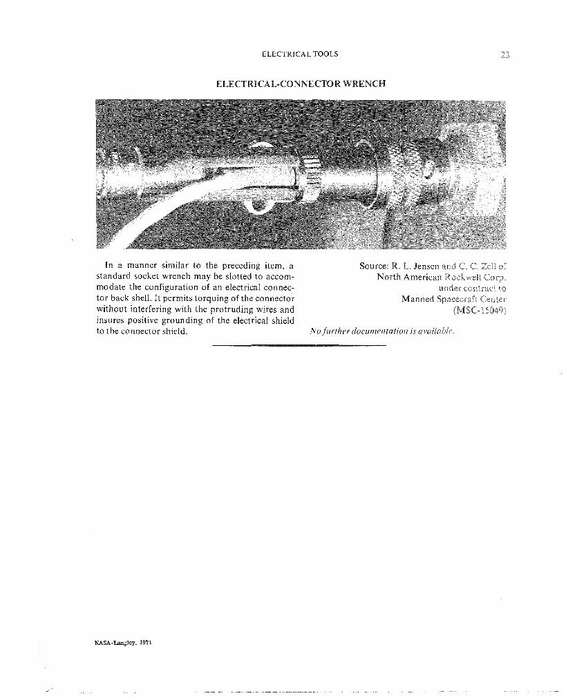
EEECTRICAL-CONNECTOR WRENCH
In a manner similar to the preceding item, a Source: R. L. Jensen and C. C. Zelf of standard socket wrench may be slotted to accom- North American RockweIE. Corp. modate the configuration of an electrical connec- under contract to tor back shell. It permits torquing of the connector Manned Spacecraft Center without interfering with the protruding wires and (MSC- 15049) insures positive grounding of the electrical shield to the connector shield. No further docurnentatio~i is availabie

POSTAGE AND FEES PAID NATIONAL ~ ~ m I C S AND -
SPACE ADMINISTRATION
POSTMASTER: 20z erable (Section I58 ~dl) Do Not Returnu
'The neronnltticnl and space nctivities of the U~zited Stntes shall be condz~cted so ns to contribt~te . . . to the expansion of ht~r~zan knozul- edge of pheno?lzena in the ntmosphere nnd space. The Adnzinistrntioa shnll provide for the widest pradicrrble nnd appropriate dissenzination of infor?~mnfion concerning its nctivities nftd the resz/lts thereof!'
-NATIONAL AERONAUTICS AND SPACE ACT OF 1358
NASA TECHNQLQGY UTILIZATION PUBLICATIONS
These describe science or technology derived from NASA's activities that may be of particula interest in commercial and other non-aerospace applications. P~iblications include:
TECH BRIEFS: Single-page descriptions of individual innovations, devices, methods, or
Technology Utilization publicatians are p a - . of NASA's formal series of scientific and
concepts. technical ~ublications. others include Tech-
I
TECHNOLOGY SURVEYS: Selected surveys nical Reports, Technical Notes, Technical
of NASA contributions to entire areas of technology. Memorandums, Contrac~or Reports, Technical
O T H ~ ~ TU PUBLICATIONS: ThesP Translations, and Special Publications.
handbooks, reports, conference proceedings, special studies, and selected bibliographies.
Details on their availability may be obtained from:
Details on the availability of these publications may be obtained from: -r-- -
National ~eronauti?; &I# Space Administration
Code KT
Washington, D.C. 20546
National Aeronautics and
Space Administration
Code KS
Washington, D.C. 20546
NATIONAL AERONAUTICS AND SPACE ADMINISTRATION Washington, D.C. 20546