HAMMOND Manual Xm2 Engl
90
Model Owner’s Manual Thank you, and congratulations on your choice of a Hammond XM-2, Drawbar Sound Module. In order to get the most out of this instrument for many years to come, please take the time to read this manual in full.
-
Upload
ciprian-oancea -
Category
Documents
-
view
84 -
download
3
Transcript of HAMMOND Manual Xm2 Engl

Model
Owner’s Manual
Thank you, and congratulations on your choice ofa Hammond XM-2, Drawbar Sound Module.In order to get the most out of this instrument formany years to come, please take the time to readthis manual in full.

Owner’s Manual
IMPORTANT SAFETY INSTRUCTIONS
WARNINGThis sign shows there is a risk of death or severe injury if this unit is not properly usedas instructed.
CAUTION
Do not open (or modify in any way) the unit or its AC adap-tor.
Do not attempt to repair the unit, or replace parts in it (exceptwhen this manual provides specific instructions directing youto do so). Refer all servicing to your retailer, the nearestHammond, or an authorized Hammond distributor, as listedon the “Service” page.
Never use or store the unit in places that are:Subject to temperature extremes (e.g., direct sunlight inan enclosed vehicle, near a heating duct, on top of heat-generating equipment)Damp (e.g., baths, washrooms, on wet floors)HumidExposed to rainDustySubject to high levels of vibration.
Be sure to use only the AC adaptor supplied with the unit.Also, make sure the line voltage at the installation matchesthe input voltage specified on the AC adaptor’s body. OtherAC adaptors may use a different polarity, or be designed for adifferent voltage, so their use could result in damage, mal-function, or electric shock.
Do not excessively twist or bend the power cord, nor placeheavy objects on it. Doing so can damage the cord, producingsevered elements and short circuits. Damaged cords are fireand shock hazards!
This unit, either alone or in combination with an amplifierand headphones or speakers, may be capable of producingsound levels that could cause permanent hearing loss. Do notoperate for a long period of time at a high volume level, or ata level that is uncomfortable. If you experience any hearingloss or ringing in the ears, you should immediately stop usingthe unit, and consult an audiologist.
Do not allow any objects (e.g., flammable material, coins,pins); or liquids of any kind (water, soft drinks, etc.) to pen-etrate the unit.
Immediately turn the power off, remove the AC adaptor fromthe outlet, and request servicing by your retailer, the nearestHammond, or an authorized Hammond distributor, as listedon the “Service” page when:
The AC adaptor, the power-supply cord, or the plug hasbeen damaged; orIf smoke or unusual odor occursObjects have fallen into, or liquid has been spilled ontothe unit; orThe unit has been exposed to rain (or otherwise has be-come wet); orThe unit does not appear to operate normally or exhibits amarked change in performance.
In households with small children, an adult should providesupervision until the child is capable of following all the rulesessential for the safe operation of the unit.
Protect the unit from strong impact.(Do not drop it!)
Do not force the unit’s power-supply cord to share an outletwith an unreasonable number of other devices. Be especiallycareful when using extension cords - the total power used byall devices you have connected to the extension cord’s outletmust never exceed the power rating (watts/amperes) for theextension cord. Excessive loads can cause the insulation onthe cord to heat up and eventually melt through.
Before using the unit in a foreign country, consult with yourretailer, the nearest Hammond, or an authorized Hammonddistributor, as listed on the “Service” page.
Do not put anything that contains water (e.g., flower vases)on this unit. Also, avoid the use of insecticides, perfumes, al-cohol, nail polish, spray cans, etc., near the unit. Swiftly wipeaway any liquid that spills on the unit using a dry, soft cloth.
WARNING
Before using this unit, please carefully read this “Safety Instructions” and use it correctly.Please be sure to keep this manual at hand even after reading it once.This “Safety Instructions” section contains very important points for securing your safety. Strictly observe the instructions, please.In this manual, the degrees of dangers and damages are classified and explained as follows:
This sign shows there is a risk of injury or material damage if this unit is not properlyused as instructed.*Material damage here means a damage to the room, furniture or animals or pets.

Introduction
In case if in the future your instrument gets too old to play or mal-functions beyond repair, please observe the instructions of thismark, or, if any question, be sure to contact your dealer or yournearest town or municipal office for its proper disposal.
The unit and the AC adaptor should be located so their loca-tion or position does not interfere with their proper ventila-tion.
Always grasp only the plug on the AC adaptor cord when plug-ging into, or unplugging from, an outlet or this unit.
At regular intervals, you should unplug the AC adaptor andclean it by using a dry cloth to wipe all dust and other accu-mulations away from its prongs. Also, disconnect the powerplug from the power outlet whenever the unit is to remainunused for an extended period of time. Any accumulation ofdust between the power plug and the power outlet can resultin poor insulation and lead to fire.
Try to prevent cords and cables from becoming entangled.Also, all cords and cables should be placed so they are out ofthe reach of children.
Never climb on top of, nor place heavy objects on the unit.
Never handle the AC adaptor or its plugs with wet handswhen plugging into, or unplugging from, an outlet of thisunit.
Before moving the unit, disconnect the AC adaptor andall cords coming from external devices.
Before cleaning the unit, turn off the power and unplugthe AC adaptor from the outlet.
Whenever you suspect the possibility of lightning in yourarea, disconnect the AC adaptor from the outlet.
CAUTION
Owner’s Manual
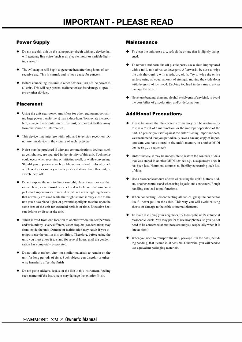
IMPORTANT - PLEASE READ
Power Supply
Do not use this unit on the same power circuit with any device thatwill generate line noise (such as an electric motor or variable light-ing system).
The AC adaptor will begin to generate heat after long hours of con-secutive use. This is normal, and is not a cause for concern.
Before connecting this unit to other devices, turn off the power toall units. This will help prevent malfunctions and/or damage to speak-ers or other devices.
Placement
Using the unit near power amplifiers (or other equipment contain-ing large power transformers) may induce hum. To alleviate the prob-lem, change the orientation of this unit; or move it farther awayfrom the source of interference.
This device may interfere with radio and television reception. Donot use this device in the vicinity of such receivers.
Noise may be produced if wireless communications devices, suchas cell phones, are operated in the vicinity of this unit. Such noisecould occur when receiving or initiating a call, or while conversing.Should you experience such problems, you should relocate suchwireless devices so they are at a greater distance from this unit, orswitch them off.
Do not expose the unit to direct sunlight, place it near devices thatradiate heat, leave it inside an enclosed vehicle, or otherwise sub-ject it to temperature extremes. Also, do not allow lighting devicesthat normally are used while their light source is very close to theunit (such as a piano light), or powerful spotlights to shine upon thesame area of the unit for extended periods of time. Excessive heatcan deform or discolor the unit.
When moved from one location to another where the temperatureand/or humidity is very different, water droplets (condensation) mayform inside the unit. Damage or malfunction may result if you at-tempt to use the unit in this condition. Therefore, before using theunit, you must allow it to stand for several hours, until the conden-sation has completely evaporated.
Do not allow rubber, vinyl, or similar materials to remain on theunit for long periods of time. Such objects can discolor or other-wise harmfully affect the finish
Do not paste stickers, decals, or the like to this instrument. Peelingsuch matter off the instrument may damage the exterior finish.
Maintenance
To clean the unit, use a dry, soft cloth; or one that is slightly damp-ened.
To remove stubborn dirt off plastic parts, use a cloth impregnatedwith a mild, non-abrasive detergent. Afterwards, be sure to wipethe unit thoroughly with a soft, dry cloth. Try to wipe the entiresurface using an equal amount of strength, moving the cloth alongwith the grain of the wood. Rubbing too hard in the same area candamage the finish.
Never use benzine, thinners, alcohol or solvents of any kind, to avoidthe possibility of discoloration and/or deformation.
Additional Precautions
Please be aware that the contents of memory can be irretrievablylost as a result of a malfunction, or the improper operation of theunit. To protect yourself against the risk of losing important data,we recommend that you periodically save a backup copy of impor-tant data you have stored in the unit’s memory in another MIDIdevice (e.g., a sequencer).
Unfortunately, it may be impossible to restore the contents of datathat was stored in another MIDI device (e.g., a sequencer) once ithas been lost. Hammond assumes no liability concerning such lossof data.
Use a reasonable amount of care when using the unit’s buttons, slid-ers, or other controls; and when using its jacks and connectors. Roughhandling can lead to malfunctions.
When connecting / disconnecting all cables, grasp the connectoritself - never pull on the cable. This way you will avoid causingshorts, or damage to the cable’s internal elements.
To avoid disturbing your neighbors, try to keep the unit's volume atreasonable levels. You may prefer to use headphones, so you do notneed to be concerned about those around you (especially when it islate at night).
When you need to transport the unit, package it in the box (includ-ing padding) that it came in, if possible. Otherwise, you will need touse equivalent packaging materials.

Introduction
BATTERY BACK UP
Your XM-2 uses a battery-backed RAM to remember your changes to the Parameters.When the battery voltage becomes low, the Display will show:
If you see these messages, you should immediately back up your parameter changes, ifyou have made any. If there is no battery installed in the unit, or if the battery iscompeletely dead, the Display will show:
After the above message is displayed, the XM-2 will re-initialize itself, and the factorydefault settings will be restored. Therefore, it is a good idea to periodically save yourdata to a sequencer.
CAUTION: Ask your dealer or store for the details how to change the batter-ies.

Owner’s Manual
Table Of ContentsIMPORTANT SAFETY INSTRUCTIONS.................................. 2IMPORTANT - PLEASE READ ............................................... 4BATTERY BACK UP .............................................................. 5MAIN FEATURES ................................................................. 9NAMES AND FUNCTIONS .................................................. 10
Front Panel ................................................................................... 10
Rear Panel ................................................................................... 11
HOOK-UP........................................ 13BASIC HOOK-UP ................................................................ 14
CONNECTION USING A SIMPLE MIDI KEYBOARD ............................... 14
CONNECTION USING A SIMPLE MIDI KEYBOARD AND THE XMc-2 .... 15
CONNECTION USING A MULTI-FUNCTIONAL MIDI KEYBOARD ............ 16
CONNECTION USING TWO MIDI KEYBOARDS ..................................... 16
CONNECTION USING MULTIPLE MIDI KEYBOARDS AND THE XMc-2 .. 17
CONNECTION OF LESLIE SPEAKER ................................... 18BASIC CONNECTION OF THE LESLIE SPEAKER .................................. 18
MIDI CONTROL OF LESLIE SPEAKER .................................................. 18
TURN ON AND PLAY...................... 19TURN ON THE POWER....................................................... 20
HOW TO TURN THE POWER ON ......................................................... 20
BACK-UP ............................................................................................ 20
RESET TO THE FACTORY SETTINGS .................................................. 20
LISTEN TO THE DEMONSTRATION .................................... 21PLAY BY THE PATCH ......................................................... 22
HOW TO CALL OUT THE PATCHES ..................................................... 22
WHAT IS “PART” ? .............................................................................. 22
PLAY WITH THE CONTROLLERS ....................................... 23PITCH BEND ....................................................................................... 23
EXPRESSION PEDAL ........................................................................... 23
FOOT SWITCH .................................................................................... 23
CREATE YOUR OWN SOUNDS ........................................... 24SELECT PATCH 128. ........................................................................... 24
MAKE THE DRAWBAR REGISTRATION ............................................... 24
ADD PERCUSSION .............................................................................. 24
ADD EFFECTS ..................................................................................... 25
VIBRATO AND CHORUS ............................................................... 25
LESLIE ......................................................................................... 25
RECORD TO THE PATCH ..................................................................... 26
SETTING UP ................................... 27SOUND ENGINE STRUCTURE ............................................ 28
SYSTEM STRUCTURE OF XM-2 .......................................................... 28
HOW TO USE THE PANEL BUTTONS ................................. 30EXAMPLE: Set Upper 8' of Drawbar registration at 5. .......................... 30
DRAWBAR (DRAWBAR registration) ................................. 31DRAWBARS™ .................................................................... 32
WHITE DRAWBARS ............................................................................ 33
BLACK DRAWBARS ............................................................................ 33
BROWN DRAWBARS .......................................................................... 33
PEDAL DRAWBARS ............................................................................ 33
DRAWBAR REGISTRATION PATTERNS ............................................... 34
PERC (PERCussion) ........................................................... 36NOTE .................................................................................................. 36
DRAWBAR CANCEL ..................................................................... 36
VIB & CHO (VIBrato and CHOrus) ..................................... 37LESLIE ............................................................................... 38PATCH................................................................................ 39
NAME THE PATCH .............................................................................. 39
RECORD A NEW PATCH ...................................................................... 40
DISPLAY AND ITS OPERATION..... 41PLAY MODE ....................................................................... 42
HOW TO READ THE DISPLAY ............................................................. 42
PANEL BUTTON MODE ...................................................... 43HOW TO READ THE DISPLAY ............................................................. 43
BUTTON OPERATION IN THIS MODE ................................................... 43
MENU MODE ..................................................................... 44HOW TO READ THE DISPLAY ............................................................. 44
BUTTON OPERATION IN THIS MENU ................................................... 44
FUNCTION MODE .............................................................. 45HOW TO READ THE DISPLAY ............................................................. 45
BUTTON OPERATION IN THIS MODE ................................................... 45
EXAMPLE: Adjusting the DECAY TIME of the Percussion [FAST] ......... 46
SHORT CUT TO THE FUNCTION MODE .............................. 48EXAMPLE: Move to the Percussion Function Mode. ........................... 48

Introduction
IN THIS MANUAL:NOTE:s and appear frequently.The NOTE: is a supplementary explanation.The are explanations of terms andapplications.
SETTING THE PARAMETERS ....... 49DRAWBAR ......................................................................... 50
Setting the Manual (LOWER and UPPER) ................................................. 50
Setting the PEDAL .................................................................................... 51
PATCH................................................................................ 52PATCH NAME ........................................................................................... 52
PATCH LOAD ............................................................................................ 52
PATCH NUMBERS ..................................................................................... 52
EFFECTIVE USE OF LINK-LOWER/PEDAL ............................................ 53
WHEN LINK LOWER/PEDAL IS ON: .............................................. 53
WHEN LINK LOWER/PEDAL IS OFF: ............................................. 53
CONTROL........................................................................... 54PITCH BEND ............................................................................................. 54
MODULATION ........................................................................................... 55
PRESSURE ............................................................................................... 55
EXPRESSION ............................................................................................ 56
FOOT SWITCH .......................................................................................... 57
DISPLAY ................................................................................................... 57
ADJUSTING THE EXPRESSION PEDAL ................................................ 58
TUNE ................................................................................. 59CUSTOM TONEWHEELS .................................................... 60
B-Type ......................................................................................................... 60
Mellow ......................................................................................................... 60
Brite ............................................................................................................. 60
PERCUSS (PERCUSSion) .................................................. 61LESLIE ............................................................................... 62
CABINET NUMBERS ................................................................................. 62
LESLIE PARAMETERS .............................................................................. 62
RECORD THE CABINETS ..................................................................... 64
OD/VIB (OverDrive / VIBrato) ............................................ 65OVERDRIVE .............................................................................................. 65
VIBRATO & CHORUS ................................................................................ 65
EQUALIZ (EQUALIZer) ....................................................... 66REVERB ............................................................................. 67MIDI .................................................................................. 68
MIDI TEMPLATE ....................................................................................... 68
MASTER ................................................................................................... 68
MIDI CHANNEL ......................................................................................... 69
MIDI TEMPLATES AND THEIR PURPOSES .......................................... 70
THE MIDI IN MODES AND THEIR FUNCTIONS ..................................... 70
KEYMAP ............................................................................ 71SPLIT ....................................................................................................... 71
MANUAL BASS ......................................................................................... 71
WHAT IS SPLIT? ...................................................................................... 71
WHAT IS MANUAL BASS? ........................................................................ 71
DEFAULT ............................................................................ 72SYSTEM ............................................................................ 73
APPENDIX ...................................... 75Part and MIDI Messages ................................................... 77MIDI Information ............................................................... 78Drawbar Data List 1 .......................................................... 79Drawbar Data List 2 .......................................................... 79System Exclusive Message ............................................... 80Global Parameters ............................................................ 81Patch Parameters .............................................................. 82Leslie Parameters ............................................................. 84System Parameters ........................................................... 84Specifications .................................................................... 86Demonstration Songs and Composers .............................. 87Factory Patches ................................................................ 88SERVICE ............................................................................ 89

Owner’s Manual

Introduction
9
ACCURATELY REPRODUCES THE TONE-WHEEL SOUND.Your new XM-2 contains (96) independent oscillating digital tone-wheels which accurately repro-duces the sound of the Vintage B-3.In addition, this module has full polyphony.
DIGITAL LESLIE / VIBRATO EFFECTS.The XM-2 module is equipped with a DSP effect generator to simulate the Scanner-Vibrato and theLeslie Speaker.The range of sounds that you can create is expanded by the use of Vibrato and Chorus effects, and bythe real sounding Leslie effects which effectively simulates the rotation of the two Rotors which arepresent in a traditional Leslie.
8-PIN LESLIE SPEAKER SOCKET.Your new XM-2 contains an 8-pin Leslie speaker socket for direct connection to our Leslie 21 SystemSpeakers.
CAN BE EXPANDED BY USE OF EXTERNAL MIDI PRODUCTS.You can connect your XM-2 with various MIDI instruments and expand its function. You can notonly play it using a single MIDI keyboard but also expand the number of keyboards (Lower Key-board and Pedal Keyboard) by connecting it with other MIDI keyboards. You can also record yourperformance to an external sequencer.
MAIN FEATURES

Owner’s Manual
10
FRONT LEFT SIDE
1. POWER Switch
This switches ON/OFF the module.
2. CONTROLLER Jack
This is the terminal for connecting the Drawbar ControllerXMc-2 (to be separately purchased).Use the exclusive cable HMC-1 for connection.
3. VOLUME Knob
Controls the total volume.
4. DISPLAY
Displays various information.
EDIT BUTTONS
5. PLAY Button
Jumps to the PLAY mode, the basic mode.
6. MENU/EXIT Button
Recalls the MENU mode. This is also used to return fromeach function mode.
7. RECORD Button
Records the Patches.This is also used for controlling the other recording.
8. PAGE Buttons
Selects Pages in the menu.
9. PARAMETER Buttons
Selects Parameters.
10. VALUE Knob
Increases and decreases the Patch or value of the selectedparameter.
11. ENTER Button
This is used for deciding the selected items.
PANEL BUTTONS
12. DRAWBAR Button
Calls out the Drawbar Registration mode.
13. PERC. Button
Calls out the Percussion Switch mode.
14. VIB. & CHO. Button
Calls out the Vibrato Switch mode.
14. LESLIE Button
Calls out the Leslie Switch mode.
NAMES AND FUNCTIONS
Front Panel
1 2 3 4
567
8
9
10
11
12 13
14 15
Introduction
11
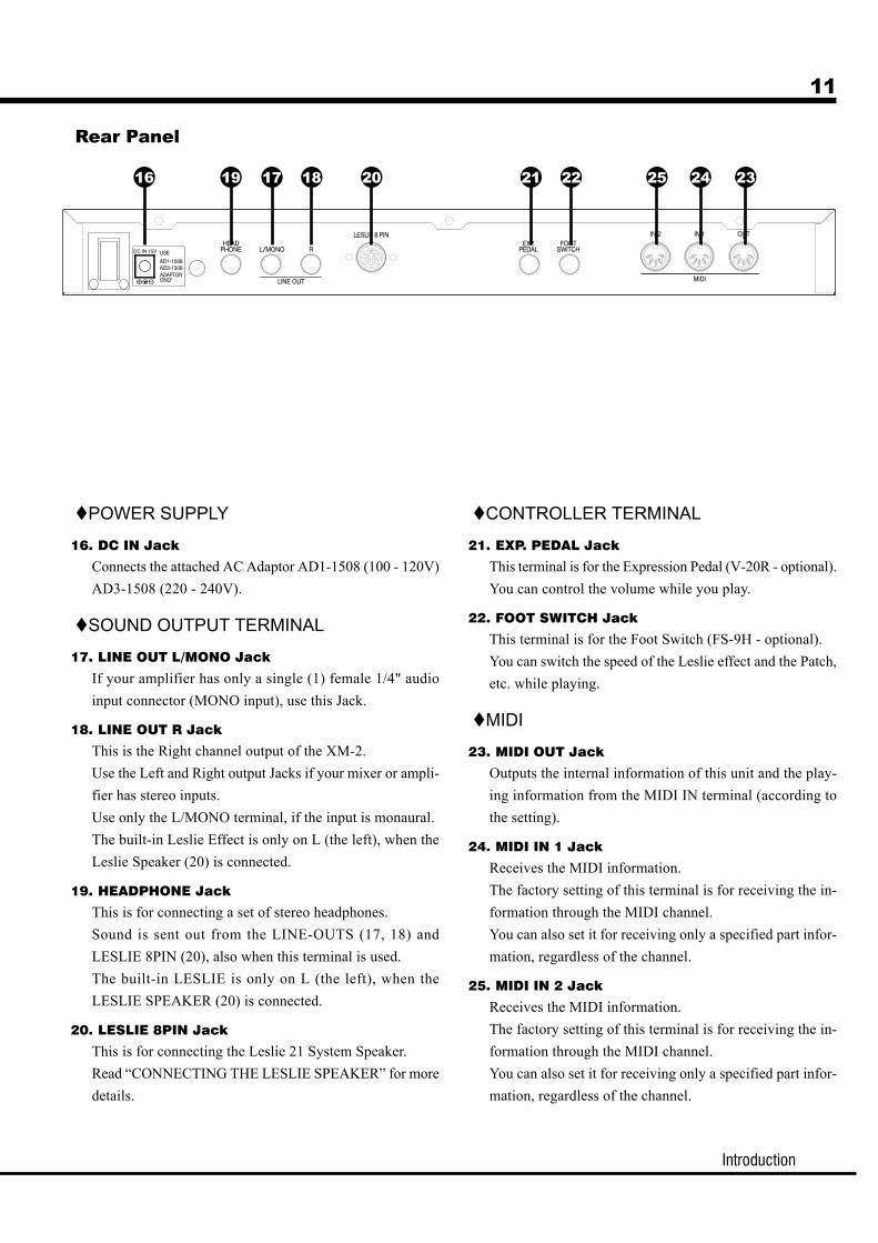
POWER SUPPLY
16. DC IN Jack
Connects the attached AC Adaptor AD1-1508 (100 - 120V)AD3-1508 (220 - 240V).
SOUND OUTPUT TERMINAL
17. LINE OUT L/MONO Jack
If your amplifier has only a single (1) female 1/4" audioinput connector (MONO input), use this Jack.
18. LINE OUT R Jack
This is the Right channel output of the XM-2.Use the Left and Right output Jacks if your mixer or ampli-fier has stereo inputs.Use only the L/MONO terminal, if the input is monaural.The built-in Leslie Effect is only on L (the left), when theLeslie Speaker (20) is connected.
19. HEADPHONE Jack
This is for connecting a set of stereo headphones.Sound is sent out from the LINE-OUTS (17, 18) andLESLIE 8PIN (20), also when this terminal is used.The built-in LESLIE is only on L (the left), when theLESLIE SPEAKER (20) is connected.
20. LESLIE 8PIN Jack
This is for connecting the Leslie 21 System Speaker.Read “CONNECTING THE LESLIE SPEAKER” for moredetails.
CONTROLLER TERMINAL
21. EXP. PEDAL Jack
This terminal is for the Expression Pedal (V-20R - optional).You can control the volume while you play.
22. FOOT SWITCH Jack
This terminal is for the Foot Switch (FS-9H - optional).You can switch the speed of the Leslie effect and the Patch,etc. while playing.
MIDI
23. MIDI OUT Jack
Outputs the internal information of this unit and the play-ing information from the MIDI IN terminal (according tothe setting).
24. MIDI IN 1 Jack
Receives the MIDI information.The factory setting of this terminal is for receiving the in-formation through the MIDI channel.You can also set it for receiving only a specified part infor-mation, regardless of the channel.
25. MIDI IN 2 Jack
Receives the MIDI information.The factory setting of this terminal is for receiving the in-formation through the MIDI channel.You can also set it for receiving only a specified part infor-mation, regardless of the channel.
Rear Panel
16 19 17 18 20 21 22 25 24 23
Owner’s Manual
12

Owner’s Manual
13
HOOK-UP

Owner’s Manual
14
Be sure to turn OFF the power of your XM-2 and connecting devices before you do thehookup.
CONNECTION USING A SIMPLE MIDI KEYBOARDThis is the simplest example.You can play as many as 3 parts by a single-manual MIDI Keyboard, using the Split and Manual Bassfunctions of the XM-2.Set the MIDI Keyboard for sending a single channel. (The channel number does not matter.)Call out “Single KBD” by the MIDI Template (P. 68) of this unit.In this case of connection, you can record to and play out of an external sequencer.
BASIC HOOK-UP
StereoHeadphones
AC Adaptor(Provided)
MIDI Keyboard
To Mixer, Amplifier etc.MIDI OUT
ExpressionPedal (optional)
Foot Switch(optional)
MIDI Sequencer,Computer etc.
(optional)

Hook-Up
15
CONNECTION USING A SIMPLE MIDIKEYBOARD AND THE XMc-2
The hook-up example shown below is for making the Drawbar Registration change at handusing the Drawbar Controller XMc-2.Set the MIDI Keyboard for sending a single channel. (The channel number does not matter.)Call out “Single KBD” by the MIDI Template (P. 68) of this unit.In this case of connection, you can record to and play out of an external sequencer.
MIDI Sequencer,Computer etc.
(optional)
MIDI OUT
MIDI Keyboard
MIDI INTO XM-2

Owner’s Manual
16
CONNECTION USING A MULTI-FUNCTIONALMIDI KEYBOARD
This hook-up shown below is for using a MIDI Keyboard that can send data to multiple MIDIchannels or an electronic organ that has multiple keyboards.Call out “By Channel” by the MIDI template (P. 68) of this unit.Set appropriate values for the MIDI channels on this unit and on each keyboard. The defaultsettings of the receiving channels on this unit are Upper = 1, Lower = 2, and Pedal = 3.
CONNECTION USING TWO MIDI KEYBOARDSThis hook-up example is for using two MIDI Keyboards; one for playing UPPER and the otherfor playing LOWER part.Set each of the MIDI Keyboard to send a single channel. (The channel numbers do not matter.)Call out “2KBD for L&U” by the MIDI Template (P. 68) of this unit.
MIDI Keyboard (for UPPER)
MIDI Keyboard (for LOWER)MIDI OUT
MIDI OUT
MIDI Keyboard (for UPPER / LOWER / PEDAL)
MIDI OUT

Hook-Up
17
CONNECTION USING MULTIPLE MIDIKEYBOARDS AND THE XMc-2
Using the Drawbar Controller XMc-2 allows you not only to change the Draw-bar Registration at hand, but also to easily build the double or triple manualsystems using the built-in MIDI IN terminal of the XMc-2.Set each MIDI Keyboard to send a single channel. (The channel number doesnot matter.)Call out “2/3KBD via XMc” by the MIDI Template (P. 68) of this unit.This example of connection allows you to record into an external sequencer.
MIDI Keyboard (for UPPER)
MIDI Keyboard (for LOWER)MIDI OUT
MIDI OUT
MIDI Pedalboard
MIDI OUT
MIDI Sequencer,Computer etc.
(optional)
MIDI INTO XM-2

Owner’s Manual
18
This unit has an 8-pin Leslie Connector which can directly connect the LeslieSpeaker.
Be sure to turn OFF the power before you connect to the Leslie Speaker.
BASIC CONNECTION OF THE LESLIESPEAKER
Connect the Leslie Speakers #2101, 2102 and the Leslie 8-pin terminal by use of the exclusive8-pin Leslie Cable LC-7-8M(= optional, to be separately purchased).
NOTE: The Leslie terminal on this unit has 8 pins. For connecting a 11-pin Leslie Speakers, youneed a Leslie Adaptor XLD-811 (= optional, to be separately purchased).
The volume of the Leslie Speakers #2101, 2102 is adjusted by the Rotary knob. Set the Sta-tionary knob at Minimum. The sound circuit on this unit is specified for a single channel.Refer to the Leslie Speaker manual as well to make sure.
MIDI CONTROL OF LESLIE SPEAKERFor MIDI-controlling the parameters (=fine adjustment of the Rotary speed, rise time, etc.) onthe Leslie #2101, 2102:
1. Connect the MIDI OUT of this unit and the MIDI IN on the Leslie Speaker by the MIDI cable.
2. Set the MIDI channel - UPPER of this unit and the MIDI channel of the Leslie Speaker to the
same channel. (P. 69 #11)
3. Set the MIDI - Leslie Parameter of this unit at “21”. (P. 69 #8)
CONNECTION OF LESLIE SPEAKER

Owner’s Manual
19
TURN ON AND PLAY

Owner’s Manual
20 TURN ON THE POWER
HOW TO TURN THE POWER ONAfter the connection is completed, turn on the power in the following order: If you do not follow thisorder, it may cause malfunctions or damages to the speakers etc.
STEPS TO TAKE1. Before turning the unit ON, make sure that the [VOLUME] knob of this unit is at MIN.
2. Turn the [POWER] switch ON. In the display, the title and then the PLAY mode appears. (See
the illustration.)It does not immediately start up after turning the power on because of circuit protec-
tion.
3. Turn on the power of the connected amplifier etc.
4. Turn the [VOLUME] knob for fine adjustment.
5. Adjust the volume of the amplifier etc.
You can adjust the volume more easily if you use the demonstration play.When you turn off the power, do the above procedure backwards. Turn OFF the ampli-
fier etc. first.
BACK-UPThis unit memorizes the status of the settings immediately before it is turned off. For this reason, thesettings when the unit is powered up is the same as they were just before the unit was shut off. Thisis called BACK-UP.
RESET TO THE FACTORY SETTINGSTo return all settings on this unit to the original Factory Settings, do the following:
STEPS TO TAKE1. Turn OFF the power on this unit.
2. Turn the power ON, holding down the [RECORD] button.
3. Keep pressing the [RECORD] button until “Loading Default” appears in the display.
4. The procedure is completed when the PLAY mode appears.
Turn On and Play
21
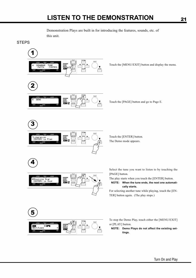
Touch the [PAGE] button and go to Page E.
Touch the [ENTER] button.The Demo mode appears.
Select the tune you want to listen to by touching the[PAGE] button.The play starts when you touch the [ENTER] button.
NOTE: When the tune ends, the next one automati-cally starts.
For selecting another tune while playing, touch the [EN-TER] button again. (The play stops.)
To stop the Demo Play, touch either the [MENU/EXIT]or [PLAY] button.
NOTE: Demo Plays do not affect the existing set-tings.
LISTEN TO THE DEMONSTRATIONDemonstration Plays are built in for introducing the features, sounds, etc. ofthis unit.
STEPS
Touch the [MENU/EXIT] button and display the menu.
1
2
3
4
5

Owner’s Manual
22 PLAY BY THE PATCHThis unit memorizes various settings up to 128 [PATCHES]. For your imme-diate play after purchasing this unit, the factory settings are recorded in thepatches 001 to 120.
HOW TO CALL OUT THE PATCHESEXAMPLE: Select 041.
GO TO THE PLAY MODEIf the present mode is not PLAY, touch [PLAY] and go to thePLAY mode.
SELECT THE PATCH NUMBERSelect Patch No. 041 by the [VALUE] knob.Call out various patches and play.When you call out a patch, not only does the Drawbar registra-tion of each part change but also the effects such as Leslie andReverb also change.
NOTE: You can set the type of parameter you call out. (P.52 #2 to 8)
WHAT IS “PART” ?A [PART] is like a player in a band or in an orchestra.Like an organ with 3 manuals can produce 3 different sounds, this unit also can produce 3 differentparts, Upper, Lower, and Pedal, because it has these 3 different parts.
NOTE: The function that makes it possible to use multiple sounds is called [Multi-Timbre].
1
2

Turn On and Play
23
EXPRESSION PEDAL
FOOT SWITCH
You can change the pitch while playing, by receiving the Pitch Bend informa-tion.
NOTE: You can adjust the amount of the pitch change by the Pitch Bendinformation. (P. 54 #1 to 4)
This is used for controlling various switches by foot instead of doing it by hand.In the default settings, “Leslie Fast” is assigned here.
NOTE: You can change the assignment of the foot switch. (P. 57 #19 to 20)
You can play more expressively if you operate the controller while playing.Let us explain in this page about the controller generally used in electronicmusical instruments. (About the unique HAMMOND Controller, let us ex-plain in the next page.)
��������
On an organ, generally not like on the piano, the velocity, i.e. touch on the keys,does not give any dynamics.However, if you connect an expression pedal ( = optional) to this unit, or receivethe expression information from the MIDI, you can change the volume and giveexpression to your play.The volume of the Expression Pedal gets maximum when fully depressed on thetoe-side and gets minimum when fully returned on the heel-side.
NOTE: Set this unit to match the model of your expression pedal. (P. 56#13)
PITCH BEND
PLAY WITH THE CONTROLLERS
This figure shows an example: XK-1.
This figure shows FS-9H ( = optional, to beseparately purchased).
This figure shows V-20R ( = optional, to beseparately purchased).
Owner’s Manual
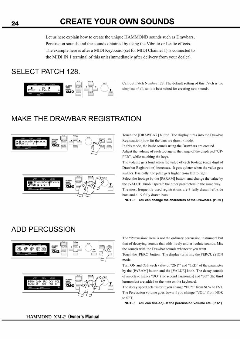
24 CREATE YOUR OWN SOUNDSLet us here explain how to create the unique HAMMOND sounds such as Drawbars,Percussion sounds and the sounds obtained by using the Vibrato or Leslie effects.The example here is after a MIDI Keyboard (set for MIDI Channel 1) is connected tothe MIDI IN 1 terminal of this unit (immediately after delivery from your dealer).
MAKE THE DRAWBAR REGISTRATION
ADD PERCUSSION
SELECT PATCH 128.Call out Patch Number 128. The default setting of this Patch is thesimplest of all, so it is best suited for creating new sounds.
Touch the [DRAWBAR] button. The display turns into the DrawbarRegistration (how far the bars are drawn) mode.In this mode, the basic sounds using the Drawbars are created.Adjust the volume of each footage in the range of the displayed “UP-PER”, while touching the keys.The volume gets loud when the value of each footage (each digit ofDrawbar Registration) increases. It gets quieter when the value getssmaller. Basically, the pitch gets higher from left to right.Select the footage by the [PARAM] button, and change the value bythe [VALUE] knob. Operate the other parameters in the same way.The most frequently used registrations are 3 fully drawn left-sidebars and all 9 fully drawn bars.
NOTE: You can change the characters of the Drawbars. (P. 50 )
The “Percussion” here is not the ordinary percussion instrument butthat of decaying sounds that adds lively and articulate sounds. Mixthe sounds with the Drawbar sounds whenever you want.Touch the [PERC] button. The display turns into the PERCUSSIONmode.Turn ON and OFF each value of “2ND” and “3RD” of the parameterby the [PARAM] button and the [VALUE] knob. The decay soundsof an octave higher “DO” (the second harmonics) and “SO” (the thirdharmonics) are added to the note on the keyboard.The decay speed gets faster if you change “DCY” from SLW to FST.The Percussion volume goes down if you change “VOL” from NORto SFT.
NOTE: You can fine-adjust the percussion volume etc. (P. 61)

Turn On and Play
25
ADD EFFECTS
LESLIE
VIBRATO AND CHORUSWarmth can be added to the sound by slightly changing the Drawbarpitch in a certain cycle.Touch the [VIB&CHO] button. The display changes to Vibrato andChorus mode.
“MODE”This sets the depth of the Vibrato effect. At OF no effect is added.As the value gets larger from 1 to 3, the effect gets deeper.
“CHORUS”Vibrato sound is mixed to the original tone, and thickness is added tothe sound when you turn this on.
This gives the effects of a live performance feelings by the feeling ofturning rotors.Touch the [LESLIE] button. The display changes to the Leslie mode.
“SW”Turn this ON to get the Leslie effects.
“S/F”This switches the Rotor speed to SLOW or FAST (2 steps). The mostpopular style is to play at SLOW basically and then to change toFAST only at the climax.
“OFF”This sets the action when the value of the parameter “SW” of theLeslie effect is OF. BRAK stands for Brake. (The Rotor graduallyslows down and then finally stops.) THRU stands for Through. (TheLeslie effect is bypassed.)
NOTE: These parameters are used for controlling, in the caseLeslie speakers are connected externally.
NOTE: Fine settings are possible for the turning speed of thebuilt-in Leslie effects etc.
In this chapter we have explained the settings you can make from the panel buttons.Let us explain in the next page about the Overdrive and Reverb; elements for creating theHAMMOND ORGAN sounds.

Owner’s Manual
26
RECORD TO THE PATCHThe settings you have made so far can be recorded or memorized to your desiredPatches.You can also freely rewrite the built-in Patches when delivered from the factory.
EXAMPLE: RECORD INTO “011”
Touch the [RECORD] button. The Record mode appears.
Select the Patch Number (011 in this example) to record to by the[VALUE] knob.
Touch the [ENTER] button. The Patch is decided and the followingis displayed in the mode for certain seconds:Recording Patch...
When the recording is completed, the display returns to the immedi-ate previous mode.
NOTE: The recorded Patch data are not lost even after thepower is turned off.
1
2
3

Owner’s Manual
27
SETTING UP

Owner’s Manual
28
SYSTEM STRUCTURE OF XM-2
SOUND ENGINE STRUCTURE
Setting Up
29
To fully enjoy playing this module, please read the following section ofthis manual.
See the illustrated System Structure of your keyboard on the left page.
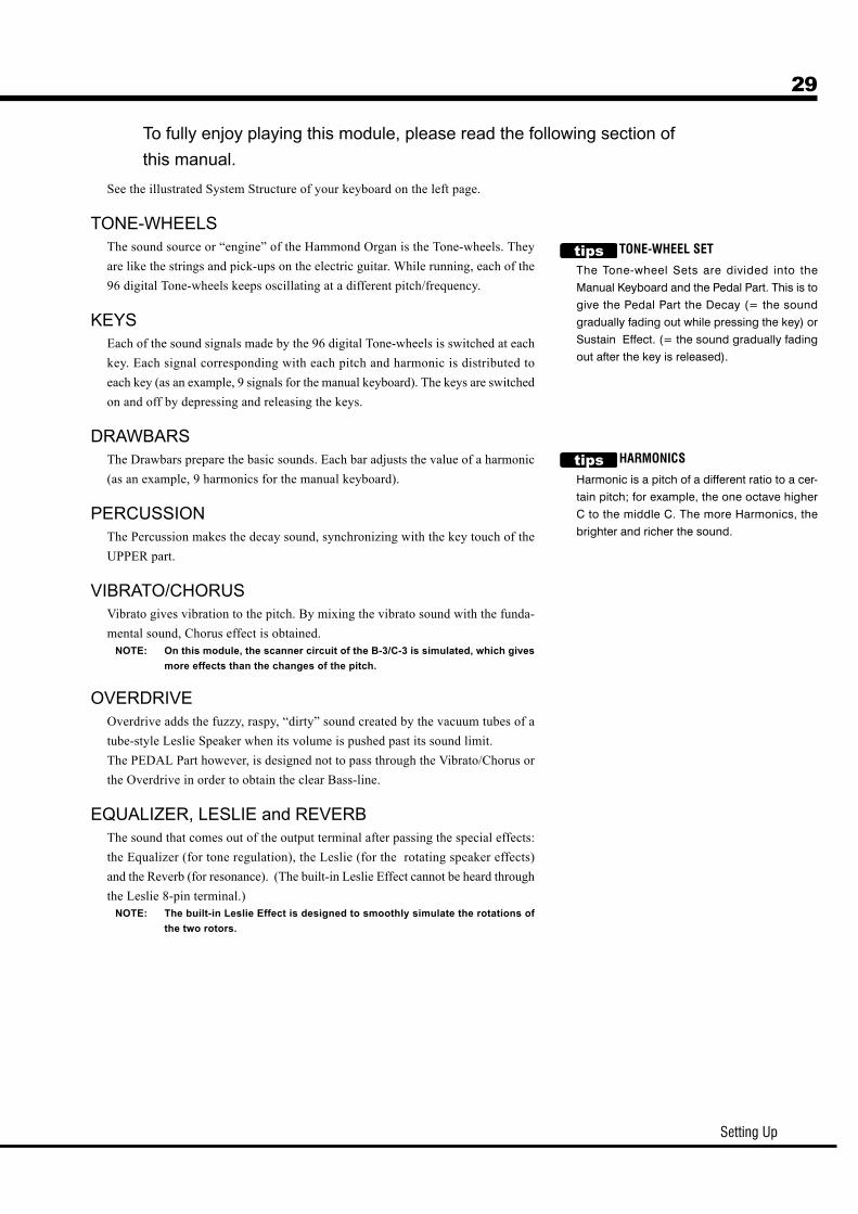
TONE-WHEELSThe sound source or “engine” of the Hammond Organ is the Tone-wheels. Theyare like the strings and pick-ups on the electric guitar. While running, each of the96 digital Tone-wheels keeps oscillating at a different pitch/frequency.
KEYSEach of the sound signals made by the 96 digital Tone-wheels is switched at eachkey. Each signal corresponding with each pitch and harmonic is distributed toeach key (as an example, 9 signals for the manual keyboard). The keys are switchedon and off by depressing and releasing the keys.
DRAWBARSThe Drawbars prepare the basic sounds. Each bar adjusts the value of a harmonic(as an example, 9 harmonics for the manual keyboard).
PERCUSSIONThe Percussion makes the decay sound, synchronizing with the key touch of theUPPER part.
VIBRATO/CHORUSVibrato gives vibration to the pitch. By mixing the vibrato sound with the funda-mental sound, Chorus effect is obtained.
NOTE: On this module, the scanner circuit of the B-3/C-3 is simulated, which givesmore effects than the changes of the pitch.
OVERDRIVEOverdrive adds the fuzzy, raspy, “dirty” sound created by the vacuum tubes of atube-style Leslie Speaker when its volume is pushed past its sound limit.The PEDAL Part however, is designed not to pass through the Vibrato/Chorus orthe Overdrive in order to obtain the clear Bass-line.
EQUALIZER, LESLIE and REVERBThe sound that comes out of the output terminal after passing the special effects:the Equalizer (for tone regulation), the Leslie (for the rotating speaker effects)and the Reverb (for resonance). (The built-in Leslie Effect cannot be heard throughthe Leslie 8-pin terminal.)
NOTE: The built-in Leslie Effect is designed to smoothly simulate the rotations ofthe two rotors.
TONE-WHEEL SET
The Tone-wheel Sets are divided into the
Manual Keyboard and the Pedal Part. This is to
give the Pedal Part the Decay (= the sound
gradually fading out while pressing the key) or
Sustain Effect. (= the sound gradually fading
out after the key is released).
HARMONICS
Harmonic is a pitch of a different ratio to a cer-
tain pitch; for example, the one octave higher
C to the middle C. The more Harmonics, the
brighter and richer the sound.

Owner’s Manual
30 HOW TO USE THE PANEL BUTTONSThe “Panel Buttons” are the 4 buttons for operating the same functions as those of theknobs and tablets on the panel of the HAMMOND ORGAN. The basic sounds of theHAMMOND ORGAN are created by the Panel Buttons, the [PARAM] button, andthe [VALUE] knob.
EXAMPLE: Set Upper 8' of Drawbar registration at 5.STEPS TO TAKE
Touch the [DRAWB] button.The display turns into Drawbar Registration mode.
Touch the [PARAM] button and move the blinking cursor(value) to UPPER 8'.
Set the value at 5 by the [VALUE] knob.
Touch [PLAY] to return to the PLAY mode.
1
2
3
4

Setting Up
31DRAWBAR (DRAWBAR registration)This mode is for setting the Drawbar Registration to create the basic sounds.
To locate this mode:Touch the [DRAWBAR] button.
The first line in the display shows the Drawbar Registration of each part, from left to right,UPPER, PEDAL, LOWER. The parts UPPER and LOWER are displayed by bar graphs, andthe PEDAL part by figures(numerals). The bottom line shows the currently selected lengthof bars (feet) and the values (levels).You can change the value by selecting the length (footage) by the [PARAM] button andturning the [VALUE] knob.

Owner’s Manual
32
The 9 Drawbars (only 2 for the PEDAL parts) on the HAMMOND ORGAN are used to createdifferent sounds. On each Drawbar the numbers 1 to 8 are marked. When the Drawbar is pushedback until you can not see the number, the Drawbar does not give any sound. When you pull outthe Drawbar to the full extent, the volume of the Drawbar is at its loudest setting.This unit has no physical Drawbars, but you can do the same things as on the real organ byoperating the displayed Drawbar Registrations.
DRAWBARS™
The pitch of each Drawbar is as shown above, when the middle C is depressed. The footagemarked (') on each Drawbar is originated from the length of the pipes of the pipe organ.The numbers 1 - 8 on each Drawbar indicate the volume of the sound to be produced as well asthe guide to simply set the Drawbar.For example, when you blow clarinet, the internal air vibrates, and the fundamental (8') and thethird harmonic (2 2/3') plus the fifth harmonic (1 3/5') come out at the same time. On this mod-ule, if you pull out 3 Drawbars, you can get the clarinet sound. If you pull out the right hand sideone of the 3 Drawbars a little longer and the left hand side one a little shorter, the element/component of the high pitch increases and a hard sound comes out. If you pull out the left handone a little longer, on the contrary, the sound gets mellow. Thus, you can make delicate changes to the sound, depending on the flow of the tune/music oryour choice/preference, by fully utilizing the Drawbars.
NOTE: You can change the characters of the Drawbars. (P. 50)
Setting Up
33
WHITE DRAWBARS
BLACK DRAWBARS
BROWN DRAWBARS
PEDAL DRAWBARS
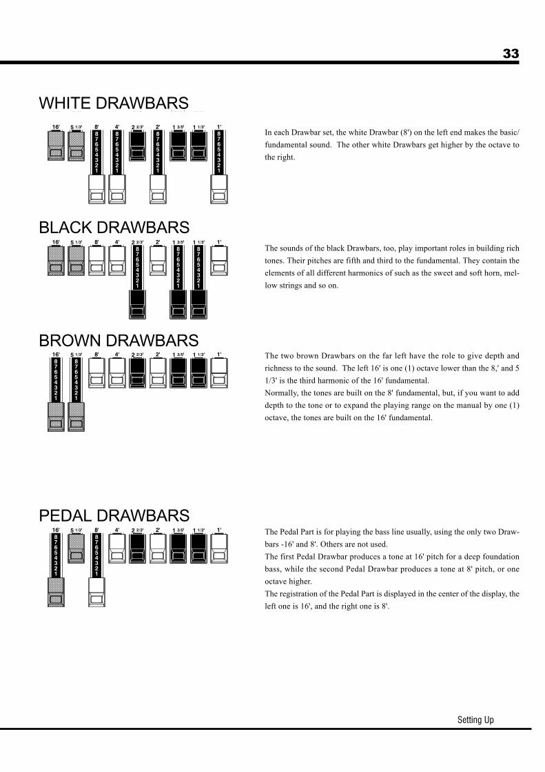
In each Drawbar set, the white Drawbar (8') on the left end makes the basic/fundamental sound. The other white Drawbars get higher by the octave tothe right.
The sounds of the black Drawbars, too, play important roles in building richtones. Their pitches are fifth and third to the fundamental. They contain theelements of all different harmonics of such as the sweet and soft horn, mel-low strings and so on.
The two brown Drawbars on the far left have the role to give depth andrichness to the sound. The left 16' is one (1) octave lower than the 8,' and 51/3' is the third harmonic of the 16' fundamental.Normally, the tones are built on the 8' fundamental, but, if you want to adddepth to the tone or to expand the playing range on the manual by one (1)octave, the tones are built on the 16' fundamental.
The Pedal Part is for playing the bass line usually, using the only two Draw-bars -16' and 8'. Others are not used.The first Pedal Drawbar produces a tone at 16' pitch for a deep foundationbass, while the second Pedal Drawbar produces a tone at 8' pitch, or oneoctave higher.The registration of the Pedal Part is displayed in the center of the display, theleft one is 16', and the right one is 8'.

Owner’s Manual
34
Bassoon 16'Clarinet 8'English Horn 8'Flugel Horn 8'French HornKinura 8'Oboe 8'Trombone 8'Trumpet 8'Tuba Sonora 8'Vox Humana 8'
44 7000 00000 6070 54000 3682 21000 5777 53000 7654 32100 0172 78600 4764 21001 8777 53000 6788 65002 7788 64000 4720 123
Flute family (2 step pattern)Accompaniment Flute 8' IAccompaniment Flute 8' IIAccompaniment Flute 8' IIIChorus of Flutes 16'Orchestral Flute 8'Piccolo 2'Stopped Flute 8'Tibia 8'Tibia 4'Tibia (Theater) 16'Wooden Open Flute 8'
00 8460 00000 3220 00000 8600 00080 8605 00200 3831 00000 0006 00300 5020 00000 7030 00000 0700 03080 8605 00400 8840 000
Reed family (triangle pattern)
DRAWBAR REGISTRATION PATTERNSThe Drawbar Registrations are usually represented by the numbers (footage values) of the 9 Drawbars.The following are the typical 4 patterns of registrations. You will see the instrument names together withthe numerical registrations on the right hand side of each pattern.The easiest way for you to obtain the basic tones you want is to remember the typical patterns of thecombined 9 Drawbars.
Setting Up
35
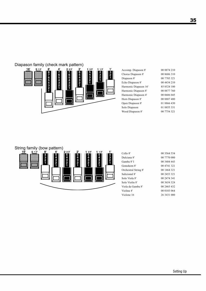
Accomp. Diapason 8'Chorus Diapason 8'Diapason 8'Echo Diapason 8'Harmonic Diapason 16'Harmonic Diapason 8'Harmonic Diapason 4'Horn Diapason 8'Open Diapason 8'Solo DiapasonWood Diapason 8'
00 8874 21000 8686 31000 7785 32100 4434 21085 8524 10000 8877 76000 0606 04500 8887 48001 8866 43001 8855 33100 7754 321
Cello 8'Dulciana 8'Gamba 8' IGemshorn 8'Orchestral String 8'Salicional 8'Solo Viola 8'Solo Violin 8'Viola da Gamba 8'Violina 4'Violone 16
00 3564 53400 7770 00000 3484 44300 4741 32100 1464 32100 2453 32100 2474 34100 3654 32400 2465 43200 0103 06426 3431 000
String family (bow pattern)
Diapason family (check mark pattern)

Owner’s Manual
36
The Percussion attack sound is a Hammond exclusive.Percussion is usually used with the Drawbar sound.
To locate this mode:Touch the [PERC.] button.
NOTEDRAWBAR CANCEL
When either the “2ND” or “3RD” is ON, 1' in the Upper Part Drawbars does not producea sound. This is the same action as on the B-3/C-3.
NOTE: You can set to play 1' Drawbar, while Percussion is ON. (P. 61 #8)
2ND (Second)The second harmonic or 4' Drawbar decay is added to the UPPER Part.To use this, set the value “ON”.
3RD (Third)The third harmonic or 2 2/3' Drawbar decay is added to the UPPER Part. By mixing it withthe Drawbars, a distinctive sound is obtained.To use this, set the value “ON”.
DCY (DeCaY)This sets the decay time for the Percussion.It is effective if you use this to play with a clear-cut rhythm in an up-tempo piece.Select “SLW” (slow) or “FST” (fast).
VOL (VOLume)This sets the volume of Percussion.Select “NOR” (normal) or “SFT” (soft).
NOTE: You can fine-adjust Percussion. (P. 61)
PERC (PERCussion)
DECAY
The piano sound gradually goes out even
if you keep the key down. This is called “de-
cay”. The violin on the contrary, keeps
sounding at a certain volume. This is called
“sustain”.

Setting Up
37
MODEThis sets the depth of Vibrato effect.No effect at OF. The larger the value gets (1 to 3), the effect gets deeper.
CHORUSThis is for switching Vibrato and Chorus effects.Turn this ON to get the Chorus effect.
NOTE: You can make fine settings for Vibrato and Chorus effects. (P. 65 #4 to 12)
VIBRATO adds warmth to the tone, by slightly changing the Drawbar pitch at acertain speed.You can also add richness to the sound by mixing the Vibrato sound with the funda-mental (= Chorus Effect).
To locate this mode:Touch the [VIB.&CHO.] button.
VIB & CHO (VIBrato and CHOrus)
Owner’s Manual
38
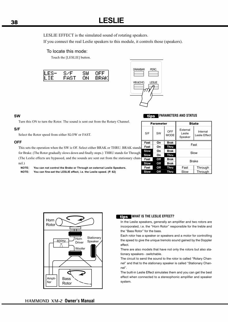
PARAMETERS AND STATUSSWTurn this ON to turn the Rotor. The sound is sent out from the Rotary Channel.
S/FSelect the Rotor speed from either SLOW or FAST.
OFFThis sets the operation when the SW is OF. Select either BRAK or THRU. BRAK standsfor Brake. (The Rotor gradually slows down and finally stops.) THRU stands for Through.(The Leslie effects are bypassed, and the sounds are sent out from the stationary chan-nel.)
NOTE: You can not control the Brake or Through on external Leslie Speakers.NOTE: You can fine-set the LESLIE effect, i.e. the Leslie speed. (P. 62)
LESLIELESLIE EFFECT is the simulated sound of rotating speakers.If you connect the real Leslie speakers to this module, it controls those (speakers).
To locate this mode:Touch the [LESLIE] button.
WHAT IS THE LESLIE EFFECT?
In the Leslie speakers, generally an amplifier and two rotors are
incorporated, i.e. the “Horn Rotor” responsible for the treble and
the “Bass Rotor” for the bass.
Each rotor has a speaker or speakers and a motor for controlling
the speed to give the unique tremolo sound gained by the Doppler
effect.
There are also models that have not only the rotors but also sta-
tionary speakers - switchable.
The circuit to send the sound to the rotor is called “Rotary Chan-
nel” and that to the stationary speaker is called “Stationary Chan-
nel”.
The built-in Leslie Effect simulates them and you can get the best
effect when connected to a stereophonic amplifier and speaker
system.
S/F SW OFFMODE
ExternalLeslie
Speaker
InternalLeslie Effect
Fast On BrakFast On ThruSlow On BrakSlow On ThruFast Off BrakSlow Off BrakFast Off Thru Fast ThroughSlow Off Thru Slow Through
Parameter State
Brake
Slow
Fast

Setting Up
39PATCHThe settings you have made can be recorded into the Patches.
NAME THE PATCHGo to the MENU.
Go to PAGE A.
Go to the PATCH function mode.
Input the NAME.
Touch the [MENU/EXIT] button.The MENU mode will be displayed.
If the PAGE A is not displayed, touch the [PAGE] button andgo to PAGE A.
Select the PATCH by using the [PARAM] button. Touch the[ENTER] button and go to the PATCH function mode.
You can store names using up to 10 letters.[PARAM] Button: moves the cursor.
[VALUE] Knob: selects letters.
You can use all the Alphabet letters large and small, signs/symbols and digits.The name input here is only temporary. Do the recording op-eration to save it, as explained on the next page.
2
3
4
1

Owner’s Manual
40
Select by the [VALUE] knob the patch number you wish to recordin. (No. 011 in this example)
2
3
Touch the [RECORD] button. The [RECORD] mode appears onthe display.
1
Touch the [ENTER] button.The Patch will be decided and the following message will appearin the display for a few seconds:Recording Patch ...
When the recording is completed, the display returns to the pre-vious one.
NOTE: The recorded Patch data is not lost even after the power isturned off.
RECORD A NEW PATCH
EXAMPLE: RECORD INTO “011”.
Touch the [RECORD] button.
Select the Patch number.
Touch the [ENTER] button.

Owner’s Manual
41
DISPLAY AND ITSOPERATION

Owner’s Manual
42 PLAY MODE
To locate this mode:1. The PLAY mode will be displayed immediately after the power is turned ON and the
start-up steps are completed.
2. Touch the [PLAY] button if the displayed mode is wrong.
The PLAY MODE is the basic display for all the operations. The necessary informa-tion for the normal play will be displayed.There are two types of PLAY MODE screens to display the Drawbar Registration.One is by showing the length of the Drawbars and the other by digits.
HOW TO READ THE DISPLAY
Sounding on MIDI NoteMessage
These two PLAY mode displays (= the bar dis-play and the digital display) will be switched ev-ery time you touch the [PLAY] button.In the bar display, the Patch name is shown butanother Patch, if assigned to the LOWER Part isnot shown.Also, the MIDI IN Note Information is displayed.
The Patch name is not shown in the digital modedisplay, but you can see the Preset Number of theLOWER Part.
Drawbar RegistrationUPPER Part/ PEDAL Part/ LOWER Part
BAR display
DIGITAL display
Patch Number :Name
Number on LOWER & PEDAL Part/Number on UPPER Part
Display And Its Operation
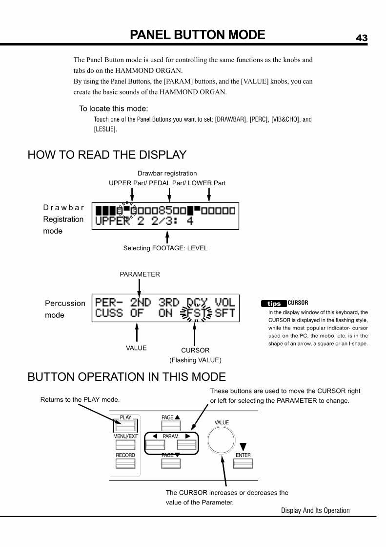
43
The Panel Button mode is used for controlling the same functions as the knobs andtabs do on the HAMMOND ORGAN.By using the Panel Buttons, the [PARAM] buttons, and the [VALUE] knobs, you cancreate the basic sounds of the HAMMOND ORGAN.
To locate this mode:Touch one of the Panel Buttons you want to set; [DRAWBAR], [PERC], [VIB&CHO], and
[LESLIE].
PANEL BUTTON MODE
CURSOR(Flashing VALUE)
Selecting FOOTAGE: LEVEL
CURSOR
In the display window of this keyboard, the
CURSOR is displayed in the flashing style,
while the most popular indicator- cursor
used on the PC, the mobo, etc. is in the
shape of an arrow, a square or an I-shape.
HOW TO READ THE DISPLAY
The CURSOR increases or decreases thevalue of the Parameter.
D r a w b a rRegistrationmode
Percussionmode
BUTTON OPERATION IN THIS MODE
Drawbar registrationUPPER Part/ PEDAL Part/ LOWER Part
PARAMETER
VALUE
Returns to the PLAY mode.These buttons are used to move the CURSOR rightor left for selecting the PARAMETER to change.

Owner’s Manual
44
The MENU mode is the path for each function.
To locate this mode:Touch the [MENU/EXIT] button.
There are several pages which contain many various FUNCTION displays. Move frompage to page and find the item where you want to go, select item by [PARAM] button,and touch the [ENTER] button to see the desired display.
PAGE
MENU MODE
BUTTON OPERATION IN THIS MENU
Returns to the PLAY mode.Moves from a page to another.
FUNCTION ITEM(If none, blank.)
HOW TO READ THE DISPLAY
Enter each FUNCTION MODE.Select the FUNCTION ITEM.

Display And Its Operation
45
The FUNCTION MODE is for making each setting and adjustment.There are many displays, but the basic operation is the same.
HOW TO READ THE DISPLAY
PAGENAME
FUNCTION MODE
This shows there arePAGEs above (or below). PARAMETER
VALUE CURSOR(Flashing VALUE)
This shows there is a PAGE onthe right (or on the left).
BUTTON OPERATION IN THIS MODE
Returns to thePLAY mode. Moves from a page to another.
This button is used to move the CURSORright or left for selecting the PARAMETERto change.The CURSOR moves to the edge of thedisplay and onto the next page (on the rightor the left), if there is one.
The CURSOR increases ordecreases the value of theParameter.

Owner’s Manual
46
EXAMPLE: Adjusting the DECAY TIME of the Percussion [FAST]
Go to the MENU Mode.
Select the PAGE.
1
2
Select the FUNCTION.3
Touch the [ENTER] button.4
Touch the [MENU] button.The [MENU] mode is displayed.
Search for the “PERCUS” page, using the [PAGE]button.“PERCUS” is on PAGE B. So select PAGE [B].
Choose the “PERCUS” by using the [PARAM] but-ton.
Touch the [ENTER] button.Now you are on the (first page) of the PercussionFunction mode.

Display And Its Operation
47
Touch the [PLAY] button to return to the PLAY mode.
Record a new Patch.The “DECAY FAST” is a Patch Parameter. It will go back to the set value if you callout the other (or current) Patch.If you want to continue to use the changed value hereafter, you must record the valueinto the Patch.
PATCH PARAMETERS
They are the Parameters to be recorded into
each Patch.
They include the Drawbar Registrations,
Parameters for panel buttons, “Decay Fast”
and many others.
The overall/general common Parameters
(which are not included in the Patches) are
called “Global Parameters.”
Move the CURSOR to the Parameter you want to change.5
Change the value.6
Back to PLAY mode.7
8
DECAY TIME is on the “DECAY” PAGE. Move tothat page using the [PAGE] button.“FAST” is on the right end. Move the CURSOR (flash-ing value) to underneath “FAST” using the [PARAM-ETER] button.
Decrease the value, using the [VALUE] button or the[VALUE] knob.
NOTE: Repeat the operation 1 - 6, if you want tochange other parameters, too.

Owner’s Manual
48 SHORT CUT TO THE FUNCTION MODEEach Panel Button has a “SHORT-CUT” capability, so that you can easily go to eachFunction mode. By holding down the button, you can easily go to the desired modedisplay. The “SHORT-CUT” mode can save time by going directly to the parametersyou want to change.
Touch and Hold
For example, if you want to change the Percussion setting, you cango to the PERCUSSION FUNCTION MODE display, by holdingdown the [PERC.] button for a few seconds. This enables the “SHORTCUT” mode.The Short-cut works on the following:
[DRAWBAR]DRAWBAR
[PERC.] PERCUSSION
[VIB&CHO] VIB/OD
[LESLIE] LESLIENOTE: You can change the time for holding down the button for
“SHORT CUT”. (P. 57 #21)
EXAMPLE: Move to the Percussion Function Mode.

Owner’s Manual
49
SETTING THEPARAMETERS

Owner’s Manual
50
Setting the Manual (LOWER and UPPER)
1. TONE-WHEELSSelect the TONE-WHEEL SET (waveform) for the manual part.
B-type: The traditional Tonewheel Sound of B-3/C-3
Mellow: Sine wave
Brite: The analog sound represented by X-5
2. CLICK - ATTACK LEVELThis allows you to set the Key-Click VOLUME of the ATTACK (= when you touch thekey). The larger the value, the louder it gets. No key-click at 0.
NOTE: When this parameter is changed, also 4. Envelope - Attack Rate will be changed toits suitable value automatically.
3. CLICK - LPFThis allows you to set the tone of the Key-Click.The setting range is 0 - 127. The larger the value, the brighter it gets.
4. ENVELOPE - ATTACK RATEThis allows you to set the speed of the Drawbar at Attack (when you touch the key). Themore the value, the slower it gets. The volume will be maximum(= loudest) at 0 at thetime you touch the key.
5. CLICK - RELEASE LEVELThis allows you to set the volume of the Key-Click at RELEASE (= when you releasethe key). The larger the value, the louder it gets. No Key-Click at 0.
NOTE: When this parameter is changed, also 6. Envelope - Release Rate will be changed toits suitable value automatically.
6. ENVELOPE - RELEASE RATEThis allows you to set the Decaying Speed of the Drawbar Sound at Release (when yourelease the key). The higher the value, the slower the RELEASE gets. The sound dies at0 at the same time as you release the key.
7. FOLD-BACK - LOWThis allows you to set at which key the 16' Drawbar starts the FOLD-BACK. (Fold-back: Repeating the same octave in a certain range on the keyboard.)The first key (= MIDI note number 36) is displayed as “1C”. The setting range is 1C -2C.
TONE-WHEEL SET
Each Tone-wheel Set allows you to make finer adjust-
ment. (P. 60)
KEY-CLICK
The “Key Click” is the noise heard every time the key is
touched or released on the B-3/C-3, as the voice is
generated by mechanically switching ON and OFF on
these models. The function on this model simulates
the good old noise.
FOLD-BACK
As the number of the tonewheels was limited on the B-
3/C-3, the organs were designed to repeat the same
octave in the upper-most or lower-most range. The fea-
ture of this model is to simulate that.
In this mode, you can set the Parameter relating to the Drawbar sound of each part.
To locate this mode:1. Touch the [MENU/EXIT] button and display the MENU, touch the [PAGE] button and select
PAGE A, choose “DRAWBAR” by the [PARAM] button, and touch the [ENTER] button.
2. Another option is to hold down the [DRAWBAR] button for a certain length of time.
DRAWBAR
1
2
3
4 5 6 7 8
9
10 11 12
13 14
15

Setting The Parameters
51
8. FOLD-BACK - HIGHThis allows you to set which key the 1' Drawbar starts to FOLD-BACK (= repeat thesame octave) in the upper-most range. The set range is 4G - 5C.
NOTE: The FOLD-BACK can be set not only on the 1' but also 1 1/3', 1 3/5', 2' and 2 2/3'Drawbars.
Setting the PEDAL
9. TONE-WHEELSThis allows you to select the Tone-wheel waveform of the PEDAL part.
Normal: The traditional B-3/C-3 Tone-wheel sound
Muted: Analog sound represented by the X-5.
Synth1: Sawtooth waveform with swept filter.
Synth2: Dull square waveform.
10. ATTACKThis allows you to set the Attack Rate and the Key-Click Volume at ATTACK and RE-LEASE.
MAX CLK: Immediately attacks and the key-click is loud.
NORM CLK: Immediately attacks and the key-click is normal.
SOFT CLK: Immediately attacks and the key-click is soft.
NO CLK: A slightly slower attacks without key-click
SLOW ATK: Slow attack without key-click
11. DECAY RATEThis allows you to determine whether to keep voicing or to decay, or set the decay time,while holding down the key.The setting range is 1 - 5 and C. The longer the value gets, the longer is the decay time.No decay at C.
12. SUSTAIN - ONThis allows you to set whether or not to use the Sustain function.
13. SUSTAIN - LENGTHThis allows you to set the Release Rate (= the decay time after you release the key),when the SUSTAIN - ON (item #12) is ON.1 is the shortest. And 5 is the longest.
14. VELOCITYThis allows you to set the response to the Velocity. The setting range is OF and 1 - 4. AtOF, the volume does not change however hard you may touch the key. As the valueincreases from 1 - 4, the sound gets louder even if you touch the key softly.
15. KEY MODEThis allows you to set the Pedal polyphony.
POLY: Makes it possible to play chords (up to 3 notes)
MONO: Only the lowest note will sound, when you play a chord.NOTE: The previously released note will be cut when you touch the new one, even when
the PEDAL is in the POLY mode and SUSTAIN is ON.NOTE: When the note-data of the Pedal are received from the MIDI IN terminal while the
value of the parameter [MIDI IN] (P. 68 #2-4) is “CH”, the Pedal produces polyphonicsound, regardless of the value.
NOTE: All the parameters in these modes are Patch Parameters. They are recorded intothe Patch.
SUSTAIN
This is the function that the volume slowly fades out
after the key is released, not like that of the synthesiz-
ers.
VELOCITY
“Velocity” is the speed of the key is depressed.
When you touch the piano hard, the hammer hits the
string hard and so the sound is loud.
The organ key is, on the other hand, generally only the
switch to open the valve, and so the sound does not
change however hard you may touch the key.
So this function is effective if you use it when the De-
cay Rate is other than C, or Decay.

Owner’s Manual
52
In this mode, you can give names to patches, set how to recall them, and set thePreset Buttons for the Drawbar Controller XMc-2.
To locate this mode:Touch the [MENU/EXIT] button and display the MENU, touch the [PAGE] button and select
PAGE A, choose “PATCH” by [PARAM] button, and touch the [ENTER] button.
PATCH NAME
1. PATCH NAME (P)This allows you to name the present Patch using up to 10 letters.Move the cursor with the [PARAM] button, and choose the let-ters with the [VALUE] knob.This change will be lost if you do not record it, same as the otherPatch Parameters.
NOTE: The parameters by the names with (P) on the tail are PatchParameters, and are recorded to each Patch.
PATCH LOADThis allows you to set the operation when you recall the Patch.
2. PATCH LOAD - UPPER (B)This allows you to set whether or not to recall the Drawbar Reg-istration of UPPER Part.
3. PATCH LOAD - LINK LOWER/PEDAL (G)This allows you to determine whether or not to recall the Draw-bar Registration of the LOWER and the PEDAL Parts.
4. PATCH LOAD - DRAWBAR (B)This allows you to determine whether or not to recall the Param-eters relating to the Drawbars of each Part, such as the TonewheelSet.
5. PATCH LOAD - PERCUSSION (B)This allows you to determine whether or not to recall the Param-eters relating to Percussion.
6. PATCH LOAD - SPLIT / MANUAL BASS (G)This allows you to determine whether or not to recall the Param-eters relating to the SPLIT or the MANUAL BASS.
7. PATCH LOAD - EQ/RV (G)This allows you to determine whether or not to recall the Param-eters relating to the EQUALIZER and REVERB.
8. PATCH LOAD - ANI/OD (G)This allows you to determine whether or not to recall the Param-eters relating to VIBRATO, OVERDRIVE and LESLIE.
PATCH NUMBERS
9. to 13. PATCH NUMBERS (G)Set the Patch Numbers for assigning to each Preset Buttonon the Drawbar Controller XMc-2.This setting can be made not only by this operation but also bytouching the Preset buttons on the XMc-2 holding down the[RECORD] button on this unit.
NOTE: Each Parameter (G) of Patch Load except LINK LOWER/PEDAL is a Global Parameter, which is recorded at thetime of setting, and common in each Patch.
PATCH
3
1
2 3 4 5 6
7 8
9 10 11 12 13

Setting The Parameters
53
WHEN LINK LOWER/PEDAL IS ON:When you call out the Patches by the [VALUE] knob of this unit,or receive the Program Change to the UPPER part, the Patches ofall parts (UPPER/LOWER/PEDAL) change.After this, to change the Patches for the POWER/PEDAL parts,send the corresponding Program Change to the LOWER part.The settings are recorded to the Patches for all parts (UPPER/LOWER/PEDAL) in the operation of this unit.To record only the settings of the LOWER/PEDAL parts to thePatches, send the Program Change to the LOWER part, holdingdown the [RECORD] button on this unit.
WHEN LINK LOWER/PEDAL IS OFF:When you call out the Patches by the [VALUE] knob of this unit,or receive the Program Change to the UPPER part, only the Patchof the UPPER part changes.To call out the Patches for the POWER/PEDAL parts, send thecorresponding Program Change to the LOWER part.The settings are recorded to the Patches only for the UPPER partin the operation of this unit.To record the settings of the LOWER/PEDAL parts to the Patches,send the Program Change to the LOWER part, holding down the[RECORD] button on this unit.
If different Patches are selected between the UPPER and the LOWER/PEDAL, the displaywill be like this.
LOWER&PEDAL UPPER
EFFECTIVE USE OF LINK-LOWER/PEDALThis is a function to set for switching and recording only at the Program Change to theLOWER part, without operating the Patches of the LOWER and the PEDAL at the ProgramChange to the [VALUE] knob or the UPPER part of this unit.The Preset Keys on B-3/C-3 are independent, key by key, and so they were operated inde-pendently. This function simulates that.

Owner’s Manual
54 CONTROLIn this mode, settings of various controllers are made.Effects can be set to the controllers mounted on the MIDIkeyboards connected to this unit such as Pitch Bend, Pres-sure, etc. Also, there are connecting terminals for the FootSwitch and the Expression Pedal on the rear panel. Youmust select and set their purpose.
To locate this mode:Touch the [MENU/EXIT] button and display the MENU, touch
the [PAGE] button and select PAGE A, choose “CONTROL”
by the [PARAM] button, and touch the [ENTER] button.
PITCH BEND
1. BEND - L&U DOWN (P)
2. BEND - L&U UP (P)
3. BEND - PEDAL DOWN (P)
4. BEND - PEDAL UP (P)These are for setting the changing range of the PITCH-BEND by the semi-tone.Both the LOWER and the UPPER PARTS change at the same time, as they use the sameTone-Wheels.The setting range is 0 - 12 for up, 0 - 24 for down.
5. BEND - MODE (P)It switches the function of the PITCH BEND information.
BEND:
You can slide the pitch by changing the PITCH BEND information.
MOTOR:
You can control the TONE-WHEEL motor. The motor turns on when it is in the
center or in the neutral position, stops when you turn down, and accelerates
when you turn up.
6. BEND - TIME (P)This sets the time for slowing down to stop or accelerating the motor when it [= MODE(5)]is in the MOTOR mode.The value ranges from 0.1[s] to 5.0[s].
7. BEND - AMPLIFIER (P)This decides whether to turn off the amplifier or not by turning down the PITCH BENDinformation.
1 2 3 4 5 6 7
8 9
10 11 12
13 14 15 16 17 18 14
19 20
21 22
MOTOR
There is no pitch-bend function on the B-3/C-3.
So some musicians turned off the power while
playing it in order to get that effect.
If the B-3/C-3 is turned off, the Tone-wheel motor
gradually slows down and stops, and the amplifier
does as well. This function is to simulate that on
this model.
HOW PITCH BEND MODE WORKS
BEND: The pitch immediately falls.
MOTOR: The pitch gradually falls down to the
set point.

Setting The Parameters
55
MODULATION
8. MODULATION - LESLIE (P)Use this for controlling the speed of the Leslie effects by the Modulation Information.
SPEED:
This changes the speed of the Leslie effects according to the Modulation Infor-
mation between Slow to Fast, continuously.
FAST:
If the Modulation value is less than 63, the mode of the Leslie effect is SLOW. If
64 or higher, FAST.
OFF:
It does not function
9. MODULATION - OVERDRIVE (P)Use this for controlling the amount of OVERDRIVE by the Modulation Information.
ON: The amount of OVERDRIVE changes according to the Modulation Information.
OF: Does not function.
PRESSURE
10. PRESSURE - LESLIE (P)Use this for controlling the speed of the Leslie effects by the Pressure Information.
SPEED:
The speed of the Leslie effects continuously changes between SLOW and FAST
in accordance with the Pressure Information.
FAST:
The mode of the Leslie effects gets SLOW when the Pressure value is less than
32, and goes FAST when the value is 81 or more.
OFF:
Does not function.
11. PRESSURE - OVERDRIVE (P)Use this for controlling the amount of OVERDRIVE by the Pressure Information.
ON: The amount of OVERDRIVE changes according to the Pressure Information.
OF: Does not function.
12. PRESSURE - PITCH BEND (P)Use this for controlling the amount of PITCH BEND by thePressure Information.
UP:
The pitch goes up in accordance with the Pressure Information.
DOWN:
The pitch goes down in accordance with the Pressure Information.
OFF:
Does not function.
NOTE: The parameters by the names with (P) on the tail are Patch Parameters, and arerecorded to each Patch. (G) is for “Global”. These parameters will be recordedwhen set, and are common in each Patch.
BRAKE ON MODULATION
If you want to “Brake” the Leslie effect by pulling
the modulation wheel forward, set the Slow Speed
to “0” on Leslie Parameter (P. 62).
Owner’s Manual
56
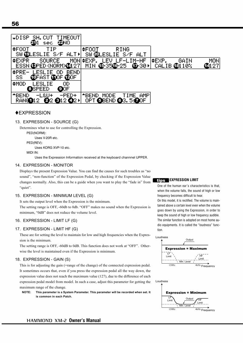
EXPRESSION
13. EXPRESSION - SOURCE (G)Determines what to use for controlling the Expression.
PED(NORM):
Uses V-20R etc.
PED(REV):
Uses KORG XVP-10 etc.
MIDI IN:
Uses the Expression Information received at the keyboard channnel UPPER.
14. EXPRESSION - MONITORDisplays the present Expression Value. You can find the causes for such troubles as “nosound”, “non-function” of the Expression Pedal, by checking if the Expression Valuechanges normally. Also, this can be a guide when you want to play the “fade in” from“quiet”.
15. EXPRESSION - MINIMUM LEVEL (G)It sets the output level when the Expression is the minimum.The setting range is OFF, -60db to 0db. “OFF” makes no sound when the Expression isminimum, “0dB” does not reduce the volume level.
16. EXPRESSION - LIMIT LF (G)
17. EXPRESSION - LIMIT HF (G)These are for setting the level to maintain for low and high frequencies when the Expres-sion is the minimum.The setting range is OFF, -60dB to 0dB. This function does not work at “OFF”. Other-wise the level is maintained even if the Expression is minimum.
18. EXPRESSION - GAIN (S)This is for adjusting the gain (=range of the change) of the connected expression pedal.It sometimes occurs that, even if you press the expression pedal all the way down, theexpression value does not reach the maximum value (127), due to the difference of eachexpression pedal model from model. In such a case, adjust this parameter for getting themaximum range of the change.
NOTE: This parameter is a System Parameter. This parameter will be recorded when set. Itis common in each Patch.
1 2 3 4 5 6 7
8 9
10 11 12
13 14 15 16 17 18 14
19 20
21 22
EXPRESSION LIMIT
One of the human ear’s characteristics is that,
when the volume falls, the sound of high or low
frequency becomes difficult to hear.
On this model, it is rectified. The volume is main-
tained above a certain level even when the volume
goes down by using the Expression, in order to
keep the sound of high or low frequency audible.
The similar function is adopted on most home au-
dio equipments. It is called the “loudness” func-
tion.
Setting The Parameters
57
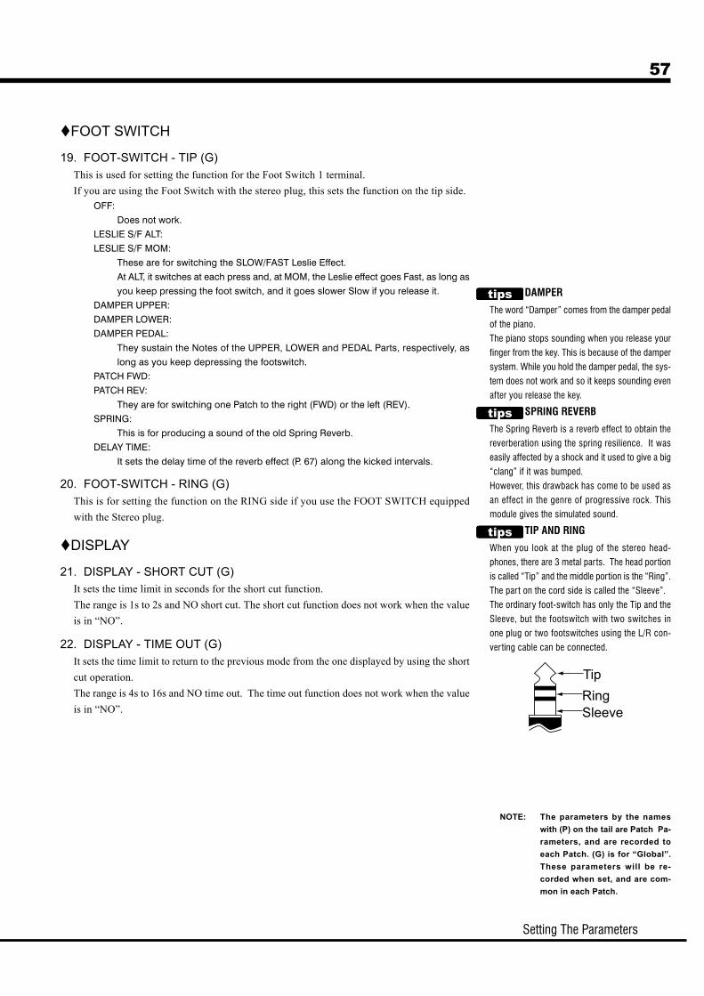
FOOT SWITCH
19. FOOT-SWITCH - TIP (G)This is used for setting the function for the Foot Switch 1 terminal.If you are using the Foot Switch with the stereo plug, this sets the function on the tip side.
OFF:
Does not work.
LESLIE S/F ALT:
LESLIE S/F MOM:
These are for switching the SLOW/FAST Leslie Effect.
At ALT, it switches at each press and, at MOM, the Leslie effect goes Fast, as long as
you keep pressing the foot switch, and it goes slower Slow if you release it.
DAMPER UPPER:
DAMPER LOWER:
DAMPER PEDAL:
They sustain the Notes of the UPPER, LOWER and PEDAL Parts, respectively, as
long as you keep depressing the footswitch.
PATCH FWD:
PATCH REV:
They are for switching one Patch to the right (FWD) or the left (REV).
SPRING:
This is for producing a sound of the old Spring Reverb.
DELAY TIME:
It sets the delay time of the reverb effect (P. 67) along the kicked intervals.
20. FOOT-SWITCH - RING (G)This is for setting the function on the RING side if you use the FOOT SWITCH equippedwith the Stereo plug.
DISPLAY
21. DISPLAY - SHORT CUT (G)It sets the time limit in seconds for the short cut function.The range is 1s to 2s and NO short cut. The short cut function does not work when the valueis in “NO”.
22. DISPLAY - TIME OUT (G)It sets the time limit to return to the previous mode from the one displayed by using the shortcut operation.The range is 4s to 16s and NO time out. The time out function does not work when the valueis in “NO”.
NOTE: The parameters by the nameswith (P) on the tail are Patch Pa-rameters, and are recorded toeach Patch. (G) is for “Global”.These parameters will be re-corded when set, and are com-mon in each Patch.
DAMPER
The word “Damper” comes from the damper pedal
of the piano.
The piano stops sounding when you release your
finger from the key. This is because of the damper
system. While you hold the damper pedal, the sys-
tem does not work and so it keeps sounding even
after you release the key.
SPRING REVERB
The Spring Reverb is a reverb effect to obtain the
reverberation using the spring resilience. It was
easily affected by a shock and it used to give a big
“clang” if it was bumped.
However, this drawback has come to be used as
an effect in the genre of progressive rock. This
module gives the simulated sound.
TIP AND RING
When you look at the plug of the stereo head-
phones, there are 3 metal parts. The head portion
is called “Tip” and the middle portion is the “Ring”.
The part on the cord side is called the “Sleeve”.
The ordinary foot-switch has only the Tip and the
Sleeve, but the footswitch with two switches in
one plug or two footswitches using the L/R con-
verting cable can be connected.

Owner’s Manual
58
ADJUSTING THE EXPRESSION PEDALWhen you use the Expression Pedal V-20R, we suggest you follow the adjusting procedure as shown below.
Plug-in the Expression Pedal V-20R to this module, and set theMinimum Volume at Zero.
Fully depress the toe side of the Expression Pedal.
Set the Expression - Source (13) at “PED (NORM)”.
Adjust the Expression - Gain (18) to the Minimum Valuewhere the Monitor (14) displays “127”.
Set the Maximum Level you want when youfully depress the toe side of the ExpressionPedal by the Master Volume knob, and alsoby the Minimum Level (15) you want whenyou depress the heel side as well.
An alternative way for setting the MinimumLevel:Set the Expression - Minimum Level (15) at“OFF”, adjusting the Minimum Volume on theExpression Pedal V-20R.
6
5
4
3
1 2Set at “0”
Adjust theMaximum Level
Adjust theMinimum Level
Adjust theMinimum Level

Setting The Parameters
59TUNEIn this mode, you can tune and transpose for playing in ensemble with the otherinstruments.
To locate this mode:Touch the [MENU/EXIT] button. The MENU appears. Select PAGE A by the [PAGE] button,
and choose the “TUNE” by the [PARAM] button, then touch the [ENTER].
1. TRANSPOSEYou can transpose the entire keyboard in semi-tone increments.The setting range is -6 to +6.Transpose effects between MIDI IN and the built-in sound engine.
2. MASTER TUNEThis is for changing the pitch of this entire keyboard.The setting range is A = 430 - 450 Hz.
NOTE: The parameters in this mode are the Global Parameters. They are recorded whenthe value is set. Also, they are common at each Patch.
1 2

Owner’s Manual
60
In this mode, you can select and regulate the Tone-Wheel Sets for the Manual Key-board parts (LOWER and UPPER).We call this “CUSTOM TONEWHEELS”.The typical 3 (or 4) types of settings are recorded when delivered from the factory.
To locate this mode:Touch the [MENU/EXIT] button and display the MENU, select PAGE B by the [PAGE] but-
ton, and then choose “B-type”, “Mellow”, or “Brite” by the [PARAM] button for the de-
sired Tonewheel Set and touch the [ENTER] button.
In addition, the Temporary (= the present setting) automatically switches to the selected
Tone-Wheel Set just selcted now.
1. CUSTOM NUMBERThis is for selecting the “CUSTOM NUMBER” to use.Each Custom Number has wheel-by-wheel parameters such as“Level”, “Cut Off Frequency” etc.
NOTE: This parameter is a Global Parameter. It is common for thesame Tone-wheel Set (= “B-type” here) of each Patch.
NOTE: You can not edit the wheel-by-wheel parameters on thismodel.
B-TypeReal B-3
This template faithfully simulates the classic model B-3.
It contains low motor hum and some leakage noise.
80's Clean
This template simulates the B-3 sounds in the 80’s. It
contains reduced leakage noise.
Noisy
This template is for passing all sounds of the picked-up
signal. It contains full motor hum and leakage noise.
Noisy 60
This template boosts noises. It contains full motor hum
and leakage noise.
MellowFull Flats
This template simulates the most ideal tone-wheel set.
Their values are same at each wheel.
Husky
This template has the characteristic of dropped middle
range.
Flute Lead
This has the characteristic of dropped bass and treble,
contrasting “Husky”.
BriteClassic X-5
This template faithfully simulates the classic model X-5.
It contains dull triangle waveform and flat output levels
on every wheel.
Voxy Full
This template has the most bright sounds. It is suitable
for surfin’ music.
Cheap Tr.s
This template simulates old transistor organs. It contains
insufficient bass and treble.
CUSTOM TONEWHEELS
LEAKAGE NOISE
On the B-3/C-3, the signal leakes in the route from the
pick-up mounted for the Tonewheels to the output ter-
minal. Thus noise (= mixed Tone-wheel sound) was
also heard, This is called “Leakage Noise”.
The “Leakage Noise” is an obstacle in making pure
tones, but it is recognized as a character now.
“Mellow” and “Brite” does not include the “Leakage
Noise”.
1

Setting The Parameters
61PERCUSS (PERCUSSion)In this mode, you can set the parameter of the PERCUSSION sound.
To locate this mode:1. Touch the [MENU/EXIT] button and display the MENU, then select PAGE B by the [PAGE]
button, choose “PERCUSS” by using the [PARAM] button and touch [ENTER] button.
2. Another option is to hold down the [PERC.] button for a certain length of time.
1. LEVEL - SOFT
2. LEVEL - NORMALThese are used for setting the Level of Percussion. SOFT is thelevel when the VOL (P. 36) is SFT, and NORMAL is the levelwhen the VOL is NOR.
3. DECAY - SLOW
4. DECAY - FASTThese are used for setting the speed of the Decay of the Percus-sion.SLOW is the speed when the DCY (P. 36) is SLW, and FAST isthe speed when the DCY button is FST.The setting range is 1 - 9 and C. The larger the value gets, thelonger gets the Decay Time. At C, no decay (= continuous).
5. KEYBOARD - TOUCHThis is used for setting the method of sound production of thePercussion.
ON: If you play legato, the notes including and after the sec-
ond note do not sound. (The envelope will not be re-
set.)
OF: Even if you play legato, all the notes produce sounds
like the piano.
6. KEYBOARD - VELOCITYControls the Volume of Percussion with Key Velocity.
ON: The faster a key is pressed, the louder the sound.
OF: It sounds at a certain volume regardless of how fast a
key is pressed.
7. KEYBOARD - KEY TRACKChanges the Percussion Volume by the note.
ON: The higher notes reduce the volume.
OF: It sounds at a certain volume regardless of notes.
8. DRAWBAR - 1' CANCELThis mutes the 1' of the UPPER part while using PERCUSSION.
ON: Mute
OF: Does not mute.
9. DRAWBAR - LEVELDecreases the volume of the UPPER Drawbars while using PER-CUSSION.
-3dB:Decreases the volume
0dB:Does not decrease the volumeNOTE: This parameter works only when the VOL is SFT.
NOTE: The parameters in those modes are all Patch Parameters.They are recorded to each Patch.
TOUCH
The B-3/C-3 had only one built-in Envelope Generator, and was not
recharged until all the UPPER Manuals were released. This looks like
a drawback, but it had the advantage that the sound did not get loose
when chords were roughly played.
1' CANCEL
The B-3/C-3 had no key contact exclusive for percussion but uses
the 1' contact for percussion. In this module, this is simulated.
DRAWBAR LEVEL
On the B-3/C-3, the Drawbar Volume gets slightly smaller if the Per-
cussion is on. This is simulated in this module.
1 2
3 4
5 6 7
8 9

Owner’s Manual
62
In this mode, you can create your own settings for the built-in Leslie effects.There are many parameters for the built-in Leslie effects,and so you can create various settings but not per each Patchindependently.The parameters are treated by the group called “CABINET”.You can select the CABINET NUMBER in the Patches.
To locate this mode:1. Touch the [MENU/EXIT] button to display the MENU. Then
select PAGE C by the [PAGE] button, select LESLIE by the
[PARAM] button, and touch [ENTER].
2. Another option is to hold down [LESLIE] button.
LESLIE
CONCEPT OF THE CABINET NUMBERSEach Cabinet represents one imaginary Leslie Speaker
prepared by the Leslie Parameter.
This parameter is the only Patch Parameter in this mode.
1
2
3 4 5 6 7 8 9
10 11 12 13 14 15
16 17
CABINET NUMBERS
1. LESLIE CABINETSHere you select the Cabinet Number to use in the Patches.The setting range is 1 - 8. The “*” will be displayed when the Leslie Parameters arechanged from this Cabinet Number.
LESLIE PARAMETERS
2. CABINET NAMEThis is for selecting the Cabinet Names.Move the cursor by the [PARAMETER] button and select letters by the [VALUE].In this mode, only the present value “Temporary” changes and there is no determiningoperation. You must record the name by doing “Recording the Cabinet” as explained inthe next paragraph. Otherwise the data will be lost.
3. SLOW SPEED - HORN
10. SLOW SPEED - BASSHere the Speed of the Rotor is set for Slow Speed.The setting range is 0, 24 - 318 rpm. It does not rotate at 0.
4. FAST SPEED - HORN
11. FAST SPEED - BASSHere the Speed of the Rotor is set for Fast mode.The setting range is 0, 375 - 453 rpm. It does not rotate at 0.
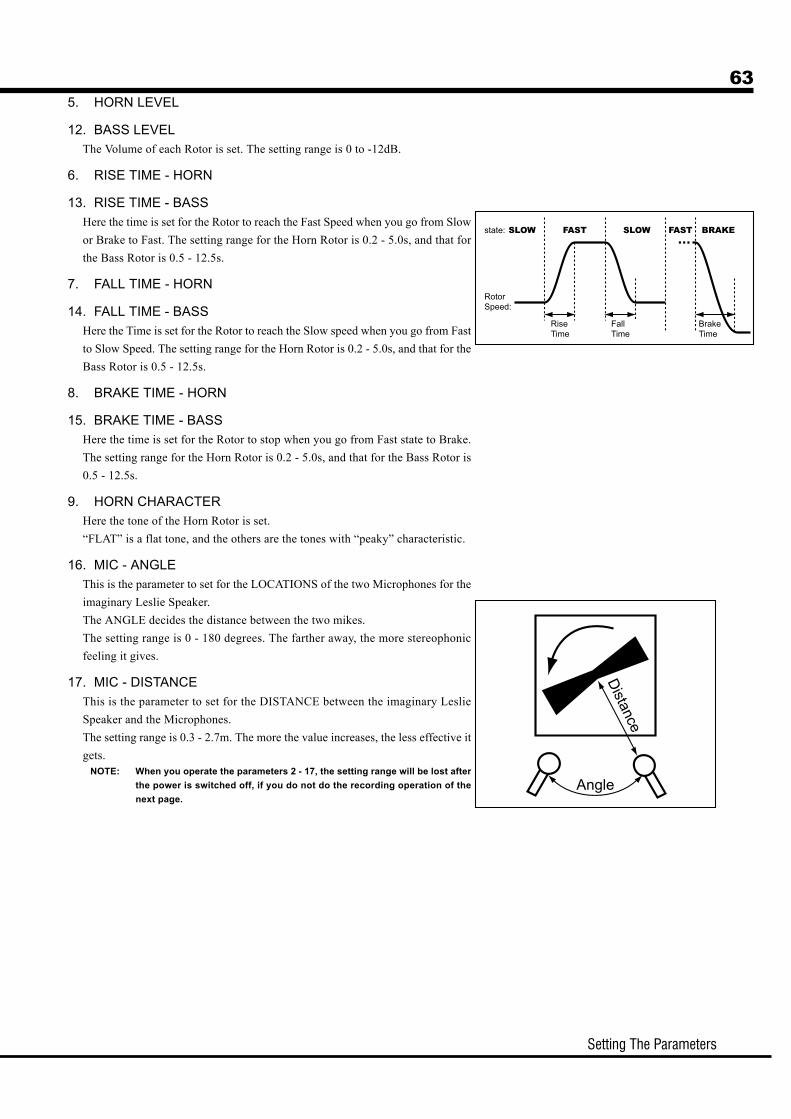
Setting The Parameters
635. HORN LEVEL
12. BASS LEVELThe Volume of each Rotor is set. The setting range is 0 to -12dB.
6. RISE TIME - HORN
13. RISE TIME - BASSHere the time is set for the Rotor to reach the Fast Speed when you go from Slowor Brake to Fast. The setting range for the Horn Rotor is 0.2 - 5.0s, and that forthe Bass Rotor is 0.5 - 12.5s.
7. FALL TIME - HORN
14. FALL TIME - BASSHere the Time is set for the Rotor to reach the Slow speed when you go from Fastto Slow Speed. The setting range for the Horn Rotor is 0.2 - 5.0s, and that for theBass Rotor is 0.5 - 12.5s.
8. BRAKE TIME - HORN
15. BRAKE TIME - BASSHere the time is set for the Rotor to stop when you go from Fast state to Brake.The setting range for the Horn Rotor is 0.2 - 5.0s, and that for the Bass Rotor is0.5 - 12.5s.
9. HORN CHARACTERHere the tone of the Horn Rotor is set.“FLAT” is a flat tone, and the others are the tones with “peaky” characteristic.
16. MIC - ANGLEThis is the parameter to set for the LOCATIONS of the two Microphones for theimaginary Leslie Speaker.The ANGLE decides the distance between the two mikes.The setting range is 0 - 180 degrees. The farther away, the more stereophonicfeeling it gives.
17. MIC - DISTANCEThis is the parameter to set for the DISTANCE between the imaginary LeslieSpeaker and the Microphones.The setting range is 0.3 - 2.7m. The more the value increases, the less effective itgets.
NOTE: When you operate the parameters 2 - 17, the setting range will be lost afterthe power is switched off, if you do not do the recording operation of thenext page.
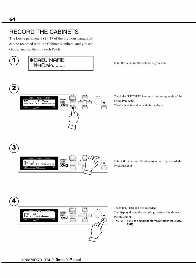
Owner’s Manual
64
RECORD THE CABINETS
Touch the [RECORD] button in the setting mode of theLeslie Parameter.The Cabinet Selection mode is displayed.
Select the Cabinet Number to record by use of the[VALUE] knob.
Touch [ENTER] and it is recorded.The display during the recording treatment is shown inthe illustration.
NOTE: If you do not want to record, just touch the [MENU/EXIT].
1
2
3
4
The Leslie parameters (2 - 17 of the previous paragraph)can be recorded with the Cabinet Numbers, and you canchoose and use them in each Patch.
Enter the name for the Cabinet as you want.

Setting The Parameters
65OD/VIB (OverDrive / VIBrato)
OVERDRIVE
1. OVERDRIVE - SWITCHTurn ON/OFF the Overdrive effect.
2. OVERDRIVE - DRIVEThis is for adjusting the Overdrive Value.The higher the value gets, the more distortion you can get.
3. OVERDRIVE - EXPRESSIONThis is for varying the amount of Overdrive by changing the Ex-pression value.
EX OD:
If you operate the Expression value, not only the vol-
ume but also the distortion will be changed.
OD EX:
The Expression value affects only the volume and not
the distortion value.
OD ONLY:
The Expression value affects only the distortion value
and not the volume.
VIBRATO & CHORUS
4. VIBRATO - RATEThis is for setting the Speed of the Vibrato and Chorus Effect.The setting range is 6.10 - 7.25 Hz.
5. VIBRATO - TREMOLOThis is for setting the Tremolo (amplitude modulation) of theVibrato and Chorus Effect.The setting range is 0 - 15.
6. VIBRATO - EMPHASISThis is for setting the Emphasis (boost the high frequency) of theChorus Effect (C1/C2/C3).The setting range is 0 - 9dB.
7. VIBRATO - DEPTH V1
8. VIBRATO - DEPTH V2
9. VIBRATO - DEPTH V3
10. VIBRATO - DEPTH C1
11. VIBRATO - DEPTH C2
12. VIBRATO - DEPTH C3These are for setting the Depth of each Vibrato and Chorus Effectmode.The setting range is 0 - 15.
NOTE: The parameters in these modes are Patch Parameters andare recorded to each Patch.
In this mode, you can change the setting relating to each Effect for Overdrive andVibrato/Chorus.
To locate this mode:Touch the [MENU/EXIT] button to display the MENU, select PAGE C by the [PAGE] button,
choose “OD/VIB” by the [PARAM] button, and then touch the [1] OD/VIB button.
1 2 3
4 5 6
7 8 9 10 11 12

Owner’s Manual
66 EQUALIZ (EQUALIZer)
1. EQ BOOST/CUT - BASS
2. EQ BOOST/CUT - MIDDLE
4. EQ BOOST/CUT - TREBLEThis is for changing the Boost/Cut of Bass, Mid-range and Treble respectively.The setting range is -9 to +9. The gain is flat at 0.
3. EQ FREQUENCY - MIDDLEThis is for changing the center frequency range - Middle (item #2).The frequency center range is 480Hz - 2.9kHz.
NOTE: These parameters are Patch Parameters and are recorded to each Patch.
THE EFFECTIVE USE OF THE MIDDLEFREQUENCY
The frequency response of the horn rotor in the
Leslie speaker is not flat. It has a peak from 1kHz
to 3kHz, The sensitive range for human ears.
When you use this module on line out without a
Leslie speaker, you can get the similar effect by
setting the FREQUENCY - MIDDLE to about 2kHz,
and the BOOST/CUT - MIDDLE to “+”.
PATCH PARAMETERS
Equalizer is a Patch Parameter designed to actively
use as one of the tone-making parameters.
However, it is not practical to use Equalizer as a
tonal complementary tool to match the location.
In such a case, if you switch OFF the P.LOAD RV/
EQ in the PATCH function mode, the Equalizer value
does not change when the patch is recalled. (P. 52
#7)
In this mode, the Equalizer settings are made.The Equalizer is an effect for adjusting the tonal quality. The built-in Equalizer inthis unit consists of 3 bands. You can divide the whole range from bass to treble into3 independent ranges and adjust/control each of them individually.
To locate this mode:Touch the [MENU/EXIT] button to display the MENU, select Page C by [PAGE]. Next,
select “EQUALIZ” by [PARAM] button and then touch [ENTER] button.
1 2 4
3

Setting The Parameters
67REVERB
1. REVERB ONThis is for switching ON/OFF the Reverb Effect.
2. DEPTHThis sets the Depth (= Volume) of the Reverb Effect.The setting range is 0 - 15. If you increase the value, it will givethe audience the impression that the player is performing in alarger room.
3. TYPEThis sets the Types of Reverb Effect.
Room 1: Inside the room (short)
Room 2: Inside the room (long)
Live: Live house
Hall 1: Concert Hall (long)
Hall 2: Concert Hall (short)
Church: Church
Plate: Iron-plate Reverb
Delay: Delay
PanDly: Panning Delay
RevDly: Reverb + Delay
4. REVERB TIMEWhen the Type (3) is set at Room 1 to Plate, it sets the Time forReverb to fade out.The setting range is 0 - 31. The higher the value, the greater theimpression of a large building.
5. DELAY TIMEWhen the Type (3) is set at Delay, PanDly, RevDly, it sets thedelaying time.The setting range is 4.7 - 1000 ms. The higher the number, thelonger the delay gets.
NOTE: You can set the Delay Time by the Foot-switch. (P. 57 #19)
6. DELAY FEEDBACKWhen the Type (3) is at Delay, PanDly, or RevDly, it sets theamount of the Feedback. (The delaying sound repeats.)The setting range is 0 - 96%. The higher the value, the higher theFeedback you get.
7. LESLIE ON REVERBThis sets the route of the Reverb and Leslie Effect.
OF: Leslie to Reverb
ON: Reverb to Leslie
NOTE: These parameters are Patch Parameters and are recordedto each Patch.
PATCH PARAMETERS
Reverb is a Patch Parameter, designed to be actively
used as one of the tone-making parameters.
However, it is not practical to use Reverb as a tonal
complementary tool to match the room/stage/hall. In
such a case, if you switch off the PLOAD RV/EQ in the
Patch function mode, the Reverb On/Off value does not
change when the patch is recalled. (P. 52 #7)
In this mode, you can change the setting for the REVERB EFFECT.
To locate this mode:Touch the [MENU/EXIT] button for the MENU display, select PAGE C by the [PAGE] button,
choose “REVERB” by the [PARAM] button, and touch the [ENTER] button.
1 2 3
4 5 6
7

Owner’s Manual
68 MIDIThis mode is for making the basic settings for the MIDI.
To locate this mode:Touch the [MENU/EXIT] button to display the MENU, select PAGE D by the [PAGE]
button. Then select “MIDI” by the [PARAM] button and touch the [ENTER] button.
MIDI TEMPLATE
1. MIDI TEMPLATEThis mode is used for easily making the purpose-by-purpose settings for each MIDI terminal.Call out a typical settings by selecting the purposes by the [PARAM] button and touching the[ENTER] button.For example, select “2/3KBD via XMc” if you want to play a full-manual organ using the Draw-bar Controller XMc-2 (= optional) and multiple MIDI Keyboards.
NOTE: The MIDI Template is a function for setting the following modes (2 to 4) by one step. Readthe details for each MIDI Template in the page 70.
MASTER
2. 3. 4. MIDI IN MODEThis is for setting the functions of each MIDI IN terminal.IN1 and IN2 set the functions for the MIDI IN 1 and 2 respectively on this unit, and the XMc setsthat of the MIDI IN of the XMc-2 connected to this unit.For example, set the Parameter IN2 to PED if you want to play the PEDAL part by the MIDImessage received at the MIDI IN2 terminal.
NOTE: Read the page 70 for the details of each MIDI IN mode.
5. PROGRAM CHANGEThis is for switching ON/OFF the transmission of the Program Change.Use the Program Change for switching the Combination Presets on this unit.ON: Transmit. OF: Don’t transmit
6. REGISTRATIONThis is for switching ON/OFF the transmission of the Drawbar Registration.ON: Transmit. OF: Don’t transmit.
7. NRPNThis is for switching ON/OFF the NRPN (= Non-Registered Parameter Number) transmission.On this unit, it switches ON/OFF the message transmission such as the Drawbar Foldback andthe Leslie ON.ON: Transmit. OF: Don’t transmit.
1
2 3 4 5 6 7 8 9
11 12 13

Setting The Parameters
69
8. LESLIEThis is used for switching the methods of the Leslie Parameter transmission.
XM: The Leslie Parameters are transmitted by the original NRPN and data of the XM-2.
21: The Leslie Parameters are transmitted by the NRPN and data for the Leslie #2101/2102. In
addition, when you select the Patch, the Leslie Parameters are transmitted.
9. RECEIVE DUMPThis is for switching ON/OFF the MEMORY DUMP receiving.On this unit, you can transmit the whole current settings by the System Exclusive Messages as aMemory Dump. However, switch it off if you do not want the settings on this unit changed byplaying the Sequencer.ON: Receive. OF: Don’t receive.
10. SEND DUMPThis is for sending the Memory Dump.Touch the [ENTER] button on this page. All the setting contents of this unit are sent out from theMIDI OUT terminal as a whole.
MIDI CHANNEL
11. UPPER
12. LOWER
13. PEDALYou can set which MIDI channel to use for transmitting each part.The options are 1 to 16, OF. It does not transmit at OF.On MIDI IN terminal, this Parameter works when the MIDI IN mode is CH.
NOTE: The settings in these modes are System Parameters. They are recorded at the same time whenthey are set, and are common in all Patches.
10

Owner’s Manual
70
MIDI TEMPLATES AND THEIR PURPOSES
THE MIDI IN MODES AND THEIR FUNCTIONSSINGLE UPPER LOWER PEDAL CHANNEL
PART played UPPER UPPER LOWER PEDAL by MIDI channel
SPLIT Yes No No No No
MANUALBASS Yes No Yes No No
SOFT-THRU Yes Yes Yes Yes No
Description
The note-data receivedat the port set in thismode basically plays theUPPER part, regardlessof the MIDI channels.By using the SPLIT andMANUAL BASSfunctions, it is possibleto play 3 separate partsby a single MIDIKeyboard. The datereceived is separatedinto each part inside andruns Soft-Thru the setMIDI channel.
The note-data receivedat this port set in thismode always plays theUPPER part, regardlessof the MIDI channel. Itruns Soft-Thru the setMIDI channel.
The note-data receivedat the port set in thismode always plays theLOWER part, regardlessof the MIDI channel.By the Manual Bassfunction, the PEDALpart can be played at thesame time. It runs Soft-Thru the set MIDIchannel.
The note-data receivedat the port set in thismode always plays thePEDAL part, regardlessof the MIDI channel. Itruns Soft-Thru the setMIDI channel.
The note-data receivedat the part set in thismode works inaccordance with theMIDI channel. Itneglects SPLIT orMANUAL BASS, norruns Soft-Thru, either.
Single KBD 2KBD for L&U By Channel 2/3KBD via XMcXM-2 IN1 SINGLE UPPER CHANNEL LOWER
XM-2 IN2 CHANNEL LOWER CHANNEL PEDAL
XMc-2 IN SINGLE UPPER CHANNEL UPPER
Description
This template is for theplay using the Split andManual Bass functionsof this unit, byconnecting a MIDIKeyboard, to be sent bya single channel, to thisunit or the DrawbarController.
This template is forplaying the UPPER andLOWER partrespectively on eachMIDI Keyboard, byconnecting 2 MIDIKeyboards sent by asingle channel to thisunit.
This template is for theplay with a connectedMIDI Keyboard, to sendout plural MIDIchannels to this unit orthe Drawbar Controller.
This template is forplaying 3 manuals,connecting a MIDIKeyboard to theDrawbar Controller, andanother MIDI Keyboardand a MIDI Pedalboardto this unit.
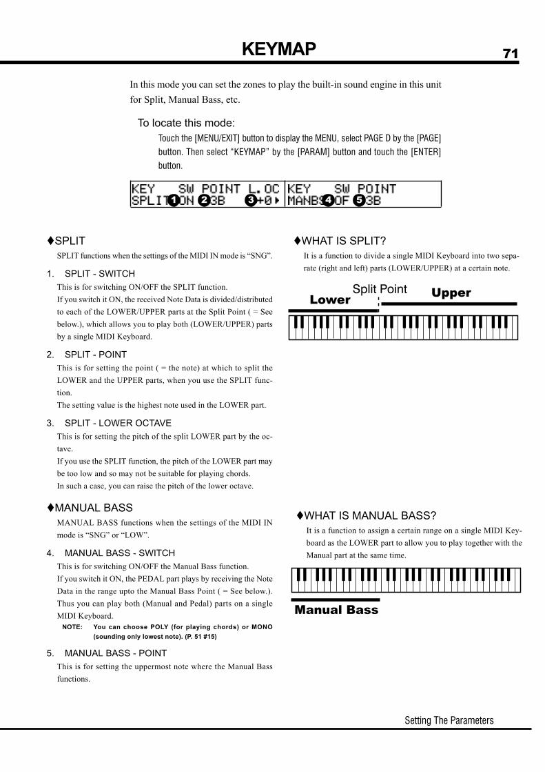
Setting The Parameters
71
In this mode you can set the zones to play the built-in sound engine in this unitfor Split, Manual Bass, etc.
To locate this mode:Touch the [MENU/EXIT] button to display the MENU, select PAGE D by the [PAGE]
button. Then select “KEYMAP” by the [PARAM] button and touch the [ENTER]
button.
KEYMAP
SPLITSPLIT functions when the settings of the MIDI IN mode is “SNG”.
1. SPLIT - SWITCHThis is for switching ON/OFF the SPLIT function.If you switch it ON, the received Note Data is divided/distributedto each of the LOWER/UPPER parts at the Split Point ( = Seebelow.), which allows you to play both (LOWER/UPPER) partsby a single MIDI Keyboard.
2. SPLIT - POINTThis is for setting the point ( = the note) at which to split theLOWER and the UPPER parts, when you use the SPLIT func-tion.The setting value is the highest note used in the LOWER part.
3. SPLIT - LOWER OCTAVEThis is for setting the pitch of the split LOWER part by the oc-tave.If you use the SPLIT function, the pitch of the LOWER part maybe too low and so may not be suitable for playing chords.In such a case, you can raise the pitch of the lower octave.
MANUAL BASSMANUAL BASS functions when the settings of the MIDI INmode is “SNG” or “LOW”.
4. MANUAL BASS - SWITCHThis is for switching ON/OFF the Manual Bass function.If you switch it ON, the PEDAL part plays by receiving the NoteData in the range upto the Manual Bass Point ( = See below.).Thus you can play both (Manual and Pedal) parts on a singleMIDI Keyboard.
NOTE: You can choose POLY (for playing chords) or MONO(sounding only lowest note). (P. 51 #15)
5. MANUAL BASS - POINTThis is for setting the uppermost note where the Manual Bassfunctions.
WHAT IS SPLIT?It is a function to divide a single MIDI Keyboard into two sepa-rate (right and left) parts (LOWER/UPPER) at a certain note.
WHAT IS MANUAL BASS?It is a function to assign a certain range on a single MIDI Key-board as the LOWER part to allow you to play together with theManual part at the same time.
1 2 3 4 5

Owner’s Manual
72 DEFAULTIn this mode, you can initialize the whole or a part of this unit back to the factorysettings.
To locate this mode:Touch the [MENU/EXIT] button to display the MENU, select PAGE D by the [PAGE] button.
Then select “DEFAULT” by the [PARAM] button and touch the [ENTER] button.
To initialize each Parameter, touch the [PARAM] button to choose the Parameter and touch[ENTER].
1. PATCHThis is for Initializing the Patch.Select the Patch you want to initialize by the [VALUE] knob. The selection range is 1 to 128,ALL ( = All Patches).
2. GLOBALThis is for initializing the Global Parameters such as Master Tune, Foot Switch assignment.
3. LESLIEThis is for initializing the Cabinet(s). Select the Cabinet you want to initialize by the [VALUE]knob.The selection range is 1 to 8, ALL ( = All Cabinets).
4. ALLThis is for initializing all the Parameters of this unit.If the system of this unit gets unstable unexpectedly, you may cure the trouble by doingDEFAULT ALL.
NOTE: Initializing all Parameters can be made by turning the power on, and holding down the[RECORD] button.
1 2 3
4

Setting The Parameters
73SYSTEMIn this mode, you can display the system information of this unit.
To locate this mode:Touch the [MENU/EXIT] button to display the MENU, select PAGE D by the [PAGE] button.
Then select “SYSTEM” by the [PARAM] button and touch the [ENTER] button.
1. VERSION - MAIN PROGRAM
2. VERSION - TONE INFORMATION
3. VERSION - DEMO SONG
4. VERSION - BOOT PROGRAMThese are the versions of each software built-in on this unit.They are only for display and not the items to set.
1 2 3
4

Owner’s Manual
74

APPENDIX

Owner’s Manual
Appendix76
[Drawbar Sound Module] Date: 26-Jun-2006Model: XM-2 Version: 1.0
Default 1 1 Upper Channel *1Changed 1 - 16 1 - 16Default 3 3Messages X XAltered ***** X
X 36 - 96: True Voice ***** 36 - 96Note ON O ONote OFF X X
After Key's X XTouch Ch's X OPitch Bender X O
1 X O Modulation6, 38 O O Data Entry MSB, LSB
11 O O Expression12 - 20 X O Drawbar Reg. Upper21 - 29 X O Drawbar Reg. Lower33, 35 X O Drawbar Reg. Pedal
48 O O Spring Shock49, 50, 51 X O Leslie On, Brake, Fast
64 O O Hold 180, 81, 82 O O Drawbar Reg. U, L, P
98, 99 O O NRPN LSB, MSB100, 101 X X RPN LSB, MSB
120 X O All Sound Off121 X O Reset All Controllers
O 0 - 127 O 0 - 127: True # ***** O 0 - 127
System Exclusive O O: Song Position X X: Song Select X X: Tune X X: Clock X X: Commands X X: Local On/Off X X: All Notes Off X O: Active Sense O O: Reset X X
Mode 1: OMNI ON, POLY Mode 2: OMNI ON, MONO O: YesMode 3: OMNI OFF, POLY Mode 4: OMNI OFF, MONO X: No*1: Lower Channel = 2, Pedal Channel = 3
MIDI Implementation Chart
Function
ProgramChange
SystemCommon
Transmitted Recognized RemarksBasicChannel
SystemReal Time
AuxMessages
Mode
NoteNumber
Velocity
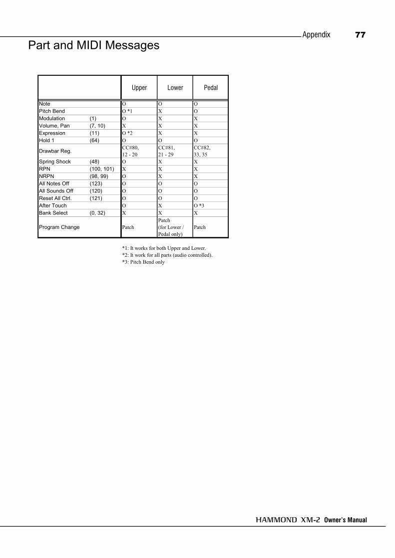
Owner’s Manual
Appendix 77Part and MIDI Messages
Upper Lower Pedal
Note O O OPitch Bend O *1 X OModulation (1) O X XVolume, Pan (7, 10) X X XExpression (11) O *2 X XHold 1 (64) O O O
Drawbar Reg. CC#80,12 - 20
CC#81,21 - 29
CC#82,33, 35
Spring Shock (48) O X XRPN (100, 101) X X XNRPN (98, 99) O X XAll Notes Off (123) O O OAll Sounds Off (120) O O OReset All Ctrl. (121) O O OAfter Touch O X O *3Bank Select (0, 32) X X X
Program Change PatchPatch(for Lower /Pedal only)
Patch
*1: It works for both Upper and Lower.*2: It work for all parts (audio controlled).*3: Pitch Bend only

Owner’s Manual
Appendix78
MIDI Information
Data EntryStatus 2nd Byte 3rd Byte
Bn 06 mm (MSB)Bn 26 ll (LSB)n=MIDI Channel Number: 0 - F(Ch.1 - 16)mm,ll=Value for the Parameter designated by RPN/NRPN.
NRPN MSB/LSBStatus 2nd Byte 3rd Byte
Bn 63 mm (MSB)Bn 62 ll (LSB)n=MIDI Channel Number: 0 - F(Ch.1 - 16)mm=Upper Byte of the Parameter Number designated by NRPN[MSB].ll=Lower Byte of same[MSB].The value set by NRPN is not reset even if "Program Change", "Reset All controllers", etc. are received.
NRPN- "Non Registered Parameter Number"The expansive range named NRPN is provided in the Control Change,which function is specific on each equipment and not defined in theMIDI Standard.When you use it, designate the parameter to control, by giving NRPN MSBand NRPN LSB (cc#98 and 99), and then set the value of the designatedparameter by the Data Entry MSB(cc#6).Once the NRPN parameter is designated, all the data entry received intothe same channel after that is regarded as the change of the value of theparameter. To avoid any mis-operation, we suggest you to set RPN Null(RPN = 7F 7F), after setting the necessary parameter value.On this sound module you can change the voice parameter by usingNRPN.
[Channel Voice Message]
Note OffStatus 2nd Byte 3rd Byte
8n kk vv or9n kk 00n=MIDI Channel Number: 0 - F(Ch.1 - 16)kk=Note Number: 00 - 7F(0 - 127)vv=Velocity(disregard): 00 - 7F(0 - 127)
Note OnStatus 2nd Byte 3rd Byte
9n kk vvn=MIDI Channel Number: 0 - F(Ch.1 - 16)kk=Note Number: 00 - 7F(0 - 127)vv=Velocity: 00 - 7F(0 - 127)
Control Change
Program Change messages etc. are received.
ModulationStatus 2nd Byte 3rd Byte
Bn 01 vvn=MIDI Channel Number: 0 - F(Ch.1 - 16)vv=Modulation Value: 00 - 7F
ExpressionStatus 2nd Byte 3rd Byte
Bn 0B vvn=MIDI Channel Number: 0 - F(Ch.1 - 16)vv=Expression Value: 00 - 7F(0 - 127)
Default Value = 7F(127)
Spring ShockStatus 2nd Byte 3rd Byte
Bn 30 vvn=MIDI Channel Number: 0 - F(Ch.1 - 16)vv=Velocity:
Leslie OnStatus 2nd Byte 3rd Byte
Bn 31 vvn=MIDI Channel Number: 0 - F(Ch.1 - 16)vv=Control Value: 00 - 7F(0 - 127) 0-63 = Off, 64-127 = On
Leslie BrakeStatus 2nd Byte 3rd Byte
Bn 32 vvn=MIDI Channel Number: 0 - F(Ch.1 - 16)vv=Control Value: 00 - 7F(0 - 127) 0-63 = Off, 64-127 = On
Leslie FastStatus 2nd Byte 3rd Byte
Bn 33 vvn=MIDI Channel Number: 0 - F(Ch.1 - 16)vv=Control Value: 00 - 7F(0 - 127) 0-63 = Off, 64-127 = On
Hold 1Status 2nd Byte 3rd Byte
Bn 40 vvn=MIDI Channel Number: 0 - F(Ch.1 - 16)vv=Control Value: 00 - 7F(0 - 127) 0-63 = Off, 64-127 = On
The value set by the Control Change is not reset even when
Pitch Bend ChangeStatus 2nd Byte 3rd Byte
En ll mmn=MIDI Channel Number: 0 - F(Ch.1 - 16)mm=Upper Bytell=Lower Byte 00 00(-8192) - 40 00(0) - 7F 7F(8191)
[Channel Mode messages]All Sounds Off
Status 2nd Byte 3rd ByteBn 78 00n=MIDI Channel Number: 0 - F(Ch.1 - 16)When this message is received, all currently-sounding notes on thecorresponding channel will be turned off immediately.
Reset All ControllersStatus 2nd Byte 3rd Byte
Bn 79 00n=MIDI Channel Number: 0 - F(Ch.1 - 16)When this message is received, the following controllers will be set totheir reset values.
Controller Reset ValuePitch Bend Change ±0 (Center)Modulation 0 (off)Expression 127 (Maximum)Hold 1 0 (off)RPN unset; previously set data will not changeNRPN unset; previously set data will not change
All Notes OffStatus 2nd Byte 3rd Byte
Bn 7B 00n=MIDI Channel Number: 0 - F(Ch.1 - 16)When All Notes Off is received, all notes on the corresponding channelwill be turned off. However if Hold 1 is On, the sound will be continueduntil these are turned off.

Owner’s Manual
Appendix 79
Drawbar Data List 1Control number: Upper 50h(80)
Lower 51h(81)Pedal 52h(82)
Data Map:
Level 16' 5 1/3' 8' 4' 2 2/3' 2' 1 3/5' 1 1/3' 1' 16' 8'0 00h(0) 09h(9) 12h(18) 1Bh(27) 24h(36) 2Dh(45) 36h(54) 3Fh(63) 48h(72) 00h(0) 09h(9)
1 01h(1) 0Ah(10) 13h(19) 1Ch(28) 25h(37) 2Eh(46) 37h(55) 40h(64) 49h(73) 01h(1) 0Ah(10)
2 02h(2) 0Bh(11) 14h(20) 1Dh(29) 26h(38) 2Fh(47) 38h(56) 41h(65) 4Ah(74) 02h(2) 0Bh(11)
3 03h(3) 0Ch(12) 15h(21) 1Eh(30) 27h(39) 30h(48) 39h(57) 42h(66) 4Bh(75) 03h(3) 0Ch(12)
4 04h(4) 0Dh(13) 16h(22) 1Fh(31) 28h(40) 31h(49) 3Ah(58) 43h(67) 4Ch(76) 04h(4) 0Dh(13)
5 05h(5) 0Eh(14) 17h(23) 20h(32) 29h(41) 32h(50) 3Bh(59) 44h(68) 4Dh(77) 05h(5) 0Eh(14)
6 06h(6) 0Fh(15) 18h(24) 21h(33) 2Ah(42) 33h(51) 3Ch(60) 45h(69) 4Eh(78) 06h(6) 0Fh(15)
7 07h(7) 10h(16) 19h(25) 22h(34) 2Bh(43) 34h(52) 3Dh(61) 46h(70) 4Fh(79) 07h(7) 10h(16)
8 08h(8) 11h(17) 1Ah(26) 23h(35) 2Ch(44) 35h(53) 3Eh(62) 47h(71) 50h(80) 08h(8) 11h(17)
ex: Set Lower 8' to level 7 via MIDI... Bx 51 19 (x=Lower Channel)
PedalUpper/Lower
Drawbar Data List 2Data Map:
Part 16' 5 1/3' 8' 4' 2 2/3' 2' 1 3/5' 1 1/3' 1'Upper 0Ch(12) 0Dh(13) 0Eh(14) 0Fh(15) 10h(16) 11h(17) 12h(18) 13h(19) 14h(20)
Lower 15h(21) 16h(22) 17h(23) 18h(24) 19h(25) 1Ah(26) 1Bh(27) 1Ch(28) 1Dh(29)
Pedal 21h(33) - 23h(35) - - - - - -
0 1 2 3 4 5 6 7 8
Value00 - 0Fh
0 - 1510 - 1Fh16 - 31
20 - 2Fh32 - 47
30 - 3Fh48 - 63
40 - 4Fh64 - 79
50 - 5Fh80 - 95
60 - 6Fh96 - 111
70 - 7Eh112- 126
7Fh127
ex: Set Lower 8' to level 7 via MIDI... Bx 17 70 (x=Upper Channel)
Control Number
Level

Owner’s Manual
Appendix80
System Exclusive MessageMemory Dump Mode Setting Exclusive Message
1.Each Packet Full Parameters ResetF0 System Exclusive F0 System Exclusive55 SUZUKI ID 55 SUZUKI ID00 Device ID 10 Device ID for DT110 Model ID MSB 42 Model ID for DT116 Model ID LSB 12 Command: DT111 Command: Data Packet 40 Address MSB[TYPE] Data Type 00 Address
02h= Setup Dump 7F Address LSB[PNH] Packet Number MSB 7F Reset[PNL] Packet Number LSB 42 Check Sum[DATA] 64 Bytes Data F7 End of Exclusive
128 Bytes nibblized ASCII When this device receives this message, it is reset toex: 7Eh = 37h, 45h the initial status of Full Parameter, and gets ready
[CHD] Check Digit for receiving the music data for this deviceLower 7 bits of XOR [DATA] correctly.
F7 End of Exclusive It takes about 50ms to process this message.Take an interval before the next message.
2.AcknowledgeF0 System Exclusive55 SUZUKI ID00 Device ID10 Model ID MSB16 Model ID LSB14 Command: Acknowledge[AK] Result: 00h=OK
05h=Check Digit Error06h=Receive Protected
[PNH] Packet Number MSB[PNL] Packet Number LSBF7 End of Exclusive
3.Hand shake communicationMaster Slave
Packet 0 -><- Acknowledge 0
Packet 1 -><- Acknowledge 1.....
This device will wait for 20ms if no acknowledgeis received and transmit the next data of thepacket number. (One Way Transfer)
NRPN SwitchF0 System Exclusive55 SUZUKI ID00 Device ID10 Model ID MSB16 Model ID LSB02 Command: NRPN Sw.[DATA] 00h=Off, 7Fh=OnF7 End Of ExclusiveWhen this device receives this message, switchTx&Rx NRPN in Control channel.

Owner’s Manual
Appendix 81Global Parameters
CategoryDATA
Parameter LSB(62)
MSB(63)
MSB(06)
Default Description
Transpose 01 00 3A - 40 - 46(-6 - 0 - 6)
40 0
Master Tune 01 02 032E - 0338 - 0342(430 - 440 - 450)
0338 440
Source 02 00 00 - 0200: Exp. Pedal (Normal)01: Exp. Pedal (Reverse)02: MIDI IN
02 MIDI IN
Min. Level 02 08 06 -35dBMin. Limit LF 02 09 09 -20dBMin. Limit HF 02 0A 07 -30dB
FootSwitch
Mode Tip 02 02 01 Leslie Fast (alternate)
Mode Ring 02 03 01 Leslie Fast (alternate)
Preset 1 02 0B 00Preset 2 02 0C 01Preset 3 02 0D 02Preset 4 02 0E 03Preset 5 02 0F 04B-Type 03 00 00 - 03 00 Real B-3Mellow 03 01 00 - 02 00 Full FlatsBrite 03 02 00 - 02 00 Classic X-5Link Lower/Pedal(Link L/P) 50 00 00, 01 (Off/On) 01 OnUpper Regist. (UK) 50 01 00, 01 (Off/On) 01 OnSplit, ManBs (INT) 50 02 00, 01 (Off/On) 01 OnReverb, Equalizer (RV/EQ) 50 03 00, 01 (Off/On) 01 OnLeslie, Vibrato (ANI/OD) 50 04 00, 01 (Off/On) 01 OnDrawbar (DRAWB) 50 05 00, 01 (Off/On) 01 OnPercussion (PERCUS) 50 06 00, 01 (Off/On) 01 On
Combi.PresetLoad
Tone-Wheelset
00 - 0900: Off01: Leslie Fast(alternate)02: Leslie Fast(momentarily)03: Damper Upper04: Damper Lower05: Damper Pedal06: Patch Fwd.07: Patch Rev.08: Spring Shock09: Delay Time
NRPNGlobal Parameters
00 - 0D(Off, -60dB - -0dB)
XMcPreset
00 - 7F (1 - 128)
Tune
Expression
same as button #

Owner’s Manual
Appendix82Patch Parameters
CategoryDATA
Parameter LSB(62)
MSB(63)
MSB(06) P. load
Internal Split On 07 00 00, 01 (Off/On)
Zone Manual Bass On 07 01 00, 01 (Off/On)Pedal Key Range High 07 04 24 - 60Split Point 07 05 24 - 5FSplit Lower Octave 07 06 00, 01 (0, +1)
Patch ParametersNRPN
SPLIT&MANBS
CategoryDATA
Parameter LSB(62)
MSB(63)
MSB(06) P. load
Name 10 Characters alwaysDrawbar Leslie On 09 00 00, 01 (Off/On)Effect Leslie Fast 09 01 00, 01 (Slow/Fast)
Leslie Brake 09 06 00, 01 (Through / Brake)Leslie Cabinet 09 07 00 - 07 (1 - 8)Leslie Mod. Ctrl 09 08 00 - 02
(Off, Speed, S/F)Leslie Press. Ctrl 09 0A 00 - 02
(Off, Speed, S/F)Vibrato Mode 09 02 00 - 03 (Off, 1 - 3)Vibrato / Chorus 09 03 00 - 01Vibrato Rate 09 04 00 - 04
(6.1 - 7.25Hz)Vibrato Tremolo 09 15 00 - 0F (0 - 15)Vibrato Cho. Emphasis 09 16 00 - 09 (0 - 9)Vibrato Depth V1 09 0F 00 - 0F (0 - 15)Vibrato Depth V2 09 10 00 - 0F (0 - 15)Vibrato Depth V3 09 11 00 - 0F (0 - 15)Vibrato Depth C1 09 12 00 - 0F (0 - 15)Vibrato Depth C2 09 13 00 - 0F (0 - 15)Vibrato Depth C3 09 14 00 - 0F (0 - 15)OD On 09 09 00, 01 (Off/On)OD Drive Level Master 09 05 00 - 3F (0 - 63)OD Exp. Ctrl 09 0C 00 - 02
00: OD to Exp01: Exp to OD02: OD Only
OD Mod. Ctrl 09 0D 00, 01 (Off/On)OD Press. Ctrl 09 0E 00, 01 (Off/On)Bend Press. Ctrl 09 17 00 - 02
(Off, Down, Up) ANI/ODEQ Bass Gain 0A 00 00 - 09 - 12
(-9 - 0 - +9 dB)EQ Mid Gain 0A 01 00 - 09 - 12
(-9 - 0 - +9 dB)EQ Treble Gain 0A 02 00 - 09 - 12
(-9 - 0 - +9 dB)EQ Mid Freq 0A 03 00 - 0A
(480 - 2.9kHz)Reverb On 0A 04 00, 01 (Off/On)Reverb Type 0A 05 00 - 09
00: Room 101: Room 202: Live House03: Hall 104: Hall 205: Church06: Plate07: Delay08: Pannning Delay09: Reverb + Delay
Reverb Depth 0A 06 00 - 0F (0 - 15)Reverb Time 0A 07 00 - 1F (0 - 31)Reverb Delay Feedback 0A 08 00 - 1F (0 - 96%)Reverb Delay Time 0A 09 00 - 3F (4.7 - 1000ms)Leslie On Reverb 0A 0A 00, 01 (Off/On)
Patch ParametersNRPN
ANI/OD
EQ/REV
EQ/REV
ANI/OD
ANI/OD

Owner’s Manual
Appendix 83
CategoryDATA
Parameter LSB(62)
MSB(63)
MSB(06) P. load
Lower 16'
Drawbars 5 1/3'8'4'2 2/3'2'1 3/5'1 1/3'1'
PedalDrawbarVoice
Voice Type 22 00 00 - 0300: Normal01: Muted02: Synth 103: Synth 2
Drawbar Attack 22 01 00 - 0400: Slow Attack01: No Click02: Soft Click03: Normal Click04: Max Click
Bend Range Down 22 02 00 - 18 (0 - 24)Bend Range Up 22 03 00 - 0C (0 - 12)Sustain On 22 04 00, 01 (Off/On)Sustain Length 22 05 00 - 04 (1 - 5)Pedal Key Mode 22 06 00, 01 (Mono/Poly)Decay Length 22 07 00 - 05 (1 - 5, Cont.)Velocity 22 08 00 - 04 (Off, 1 - 4)
Pedal 16'
Drawbars 8'see Drawbar Data List
for details
see Drawbar Data Listfor details
Link L/P
Link L/P
Link L/P
NRPNLower Patch ParametersCategory
DATAParameter LSB
(62)MSB(63)
MSB(06) P. load
Upper/LowerDrawbarVoice
Voice Type 20 00 00 - 0200: B-Type01: Mellow02: Brite
Drawbar Click Attack 20 01 00 - 0F (0 - 15)Drawbar Click Release 20 02 00 - 0F (0 - 15)Drawbar Env. Attack 20 03 00 - 0F (0 - 15)Drawbar Env. Release 20 04 00 - 0F (0 - 15)Fold Back Low 20 05 00 - 0C (C1 - C2)Fold Back High 20 06 2B - 30 (G4 - C5)Bend Range Down 20 07 00 - 18 (0 - 24)Bend Range Up 20 08 00 - 0C (0 - 12)Bend Mode 20 0A 00 - 01 (Bend / Motor)Bend Time 20 0B 00 - 31 (0.1 - 5.0s)Bend Amplitude 20 0C 00 - 01 (Off/On)Drawbar Click LPF 20 09 00 - 7F (0 - 127)
Percussion Second On 08 00 00, 01 (Off/On)Voice Third On 08 01 00, 01 (Off/On)
Decay Fast 08 02 00, 01 (Off/On)Soft 08 03 00, 01 (Off/On)Level Soft 08 04 00 - 0F (1 - 16)Level Normal 08 05 00 - 0F (1 - 16)Decay Fast 08 06 00 - 09 (1 - 9, C)Decay Slow 08 07 00 - 09 (1 - 9, C)Touch 08 08 00, 01 (Off/On)Velocity 08 09 00, 01 (Off/On)Key Track 08 0A 00, 01 (Off/On)Drawbar 1' Cancel 08 0B 00, 01 (Off/On)Drawbar Level 08 0C 00, 01 (0, -3dB)
Upper 16'Drawbars 5 1/3'
8'4'2 2/3'2'1 3/5'1 1/3'1'
Patch ParametersNRPN
see Drawbar Data Listfor details UPPER
DRAWB
PERCUS
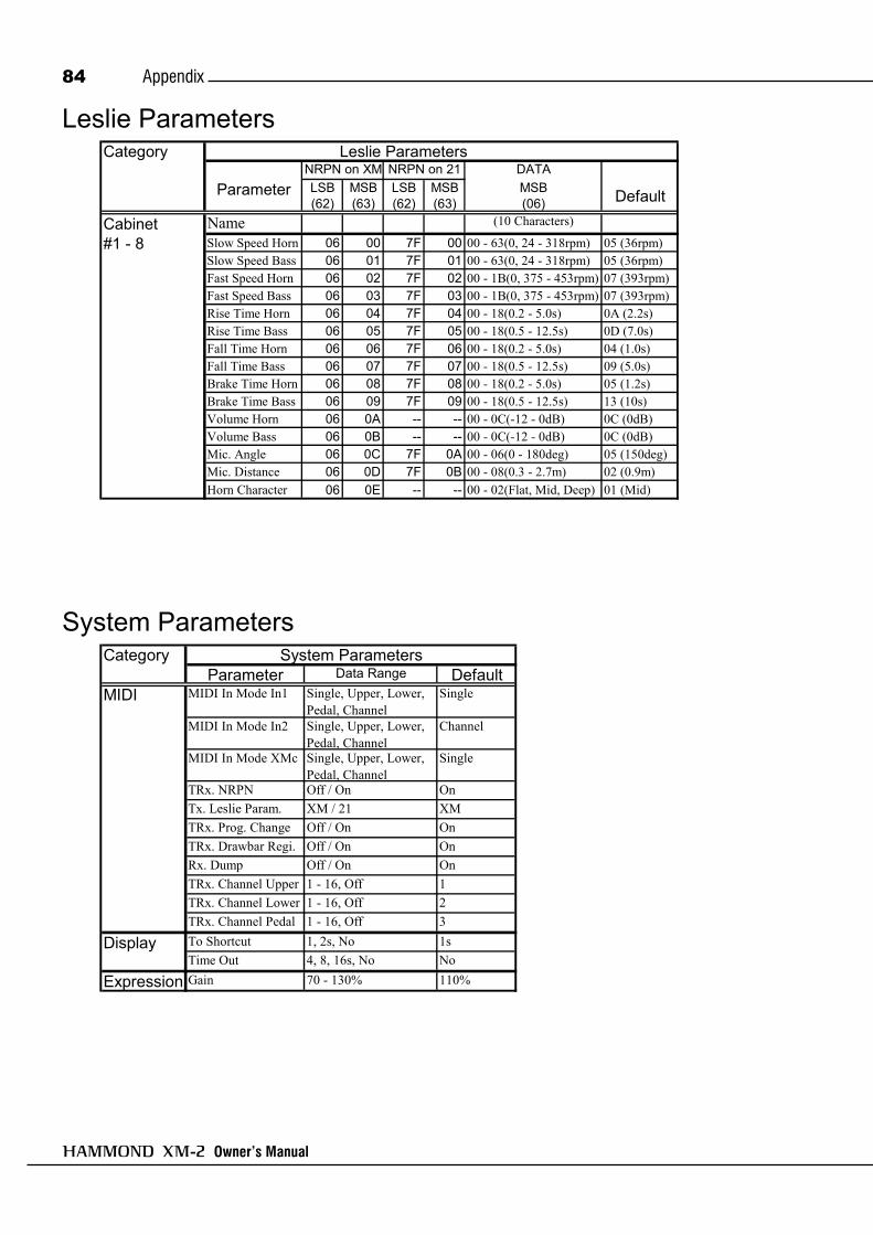
Owner’s Manual
Appendix84
Leslie Parameters
System ParametersCategory
Parameter Data Range DefaultMIDI MIDI In Mode In1 Single, Upper, Lower,
Pedal, ChannelSingle
MIDI In Mode In2 Single, Upper, Lower,Pedal, Channel
Channel
MIDI In Mode XMc Single, Upper, Lower,Pedal, Channel
Single
TRx. NRPN Off / On OnTx. Leslie Param. XM / 21 XMTRx. Prog. Change Off / On OnTRx. Drawbar Regi. Off / On OnRx. Dump Off / On OnTRx. Channel Upper 1 - 16, Off 1TRx. Channel Lower 1 - 16, Off 2TRx. Channel Pedal 1 - 16, Off 3
Display To Shortcut 1, 2s, No 1sTime Out 4, 8, 16s, No No
Expression Gain 70 - 130% 110%
System Parameters
CategoryDATA
Parameter LSB(62)
MSB(63)
LSB(62)
MSB(63)
MSB(06) Default
Name (10 Characters)
Slow Speed Horn 06 00 7F 00 00 - 63(0, 24 - 318rpm) 05 (36rpm)Slow Speed Bass 06 01 7F 01 00 - 63(0, 24 - 318rpm) 05 (36rpm)Fast Speed Horn 06 02 7F 02 00 - 1B(0, 375 - 453rpm) 07 (393rpm)Fast Speed Bass 06 03 7F 03 00 - 1B(0, 375 - 453rpm) 07 (393rpm)Rise Time Horn 06 04 7F 04 00 - 18(0.2 - 5.0s) 0A (2.2s)Rise Time Bass 06 05 7F 05 00 - 18(0.5 - 12.5s) 0D (7.0s)Fall Time Horn 06 06 7F 06 00 - 18(0.2 - 5.0s) 04 (1.0s)Fall Time Bass 06 07 7F 07 00 - 18(0.5 - 12.5s) 09 (5.0s)Brake Time Horn 06 08 7F 08 00 - 18(0.2 - 5.0s) 05 (1.2s)Brake Time Bass 06 09 7F 09 00 - 18(0.5 - 12.5s) 13 (10s)Volume Horn 06 0A -- -- 00 - 0C(-12 - 0dB) 0C (0dB)Volume Bass 06 0B -- -- 00 - 0C(-12 - 0dB) 0C (0dB)Mic. Angle 06 0C 7F 0A 00 - 06(0 - 180deg) 05 (150deg)Mic. Distance 06 0D 7F 0B 00 - 08(0.3 - 2.7m) 02 (0.9m)Horn Character 06 0E -- -- 00 - 02(Flat, Mid, Deep) 01 (Mid)
NRPN on XM
Cabinet#1 - 8
Leslie ParametersNRPN on 21

Owner’s Manual
Appendix 85

Owner’s Manual
Appendix86Specifications
Sound Generator2 x VASE III asDigital Tone-wheels
Harmonic DrawbarsPitches
9 Pitches (Upper and Lower)2 Pitches (Pedal)
WaveformB-type/Mellow/Brite (Upperand Lower)Muted/Normal/Synth1/Synth2(Pedal)
PercussionHarmonics
Second, ThirdAdjustable
Fast Decay, SoftTouch, Velocity,Decay (Fast, Slow)Level (Soft, Normal)
TuningMaster
430 - 450 1Hz StepsTranspose
-6 - 0 - +6 semitones
EffectsInternal Leslie
On, Fast, BrakeDigital, 2 Rotors
Vibrato and ChorusV1, V2, V3, C1, C2, C3Upper&Lower On/OffSpeed: 5(6.10 - 7.25Hz)
OverdriveDigital Overdrive
Equalizer3 Bands
Reverb10 Programs
Sustain5 Lengths (Pedal)
KeymapFunctions
SplitManual Bass
AdjustableSplit PointLower OctavePedal Top key
Patches128 Patches
Display20-characters, 2 lineswith 12 control switchesand Rotary encoder
StorageNone
MIDITemplates: 4
ConnectionsDC Input (15V)MIDI In1, In2, OutExp. Pedal (Phone Jack),Foot Switch,Line Out L/Mono, R,Headphones,8-pin Leslie
AccessoryAC Adaptor
AD1-1508 (100 - 120V)AD3-1508 (220 - 240V)
Dimension396(W) x 172 (D) x 50(H) mm
Weight1.8 kg

Demonstration Songs and Composers
Songs / Composers
1. Touch the [MENU/EXIT] Button.2. Select page 4 by [PAGE] Button.3. Touch the [ENTER] Button.
Playing the demonstration performance:
Joey DeFrancescoJoey started playing at the age of four. He recalls,“I could just play. I was already hearing JimmySmith and stuff like that around the house. Thenone time my Dad, “Papa John” DeFrancesco,brought the Hammond organ home from a gig.When I heard that sound I really got into it. MyDad guided me in the right direction, the do’sand the don’ts, but he was never very forcefulabout it.” At the age of 10, Joey was alreadyplaying for money on weekend gigs. By highschool, he was working steadily around Phila-delphia, receiving first-hand instruction from thetop-shelf organists who come through the citysuch as Jimmy Smith, Jack McDuff, and numer-ous others. His high visibility career kicked offwhen Miles Davis asked Joey to join his late 80sband. Joey then signed a contract with Columbiathat resulted in five records from 1989 to 1994.With the release of his album, “All of Me” in1989, Joey emerged on the jazz scene. The glo-bal jazz community has credited Joey and his re-cordings, from the late 1980s and early 1990s, asthe singular sensation for rekindling a love forthe Hammond B-3 organ. In 2003, Joey and hisband released their latest hit CD, “Falling in LoveAgain”. This CD featured the Hammond “New”B-3 organ. For the year 2002/2003, the maga-
zine Downbeat chose Joey as “the Jazz Organistof the Year”. Currently Joey is very active atHammond Suzuki. Besides participating at dealerpromotions, national conventions, concerts, andclinics, he contributes to Hammond product de-velopment.
Tony MonacoTony started playing the accordion when he waseight years old. When he was twelve, he was givena Jimmy Smith album and instantly knew thatJazz Organ was his calling. Tony began playingin Jazz nightclubs around Columbus Ohio whilehe was still learning the art of Hammond B3 or-gan. He was influenced by hometown Organistssuch as Hank Marr and Don Patterson. Tony’snewfound fascination led him to jazz organ leg-ends Jimmy McGriff, Richard “Groove” Holmes,Charles Earland, Jack McDuff, and Dr. LonnieSmith. Here he found an unlimited source of in-spiration ; he just couldn’t get enough! On Tony’ssixteenth birthday, he received a phone call fromJimmy Smith. This was a great honor and reallyboosted his enthusiasm as an organist. When hewas twenty, Jimmy Smith invited Tony to comeplay with him at his club in Woodland Hills LA.,California. An experience Tony would never for-get. In April 2000, Tony met jazz Organist JoeyDeFrancesco while Joey was playing in Colum-bus, Ohio. The two of them became instantfriends. Joey recognized Tony’s talents right awayand offered to produce a CD for him. Tony’s re-cording “Burnin’ Grooves” sparked internationalattention. Tony now travels and plays the “NewB3” organ as his relationship with HammondSuzuki has grown.
Daisuke KawaiStarted music career as a studio musician in 1989.Has supported Cornelius, Shinji Takeda and, re-cently, the Morning Musume, Ayumi Hamasaki,and coba, etc.Actively performing with his own band “ToneWheels”, and the new unit “Opus”.
Deryl WinstonDeryl Winston is a long time resident of San Diego.He began playing the Hammond Organ at age 14 whilestill living in his native home of Seattle Washington.Deryl was tutored by two of the finest Gospel musi-cians in the form of his mother Alice Winston (a con-cert pianist) and Aunt Jean McGraw (Hammond Or-ganist). It was not long before many in the Seattlearea became familiar with Deryl and the amazing tal-ent and skill he showed on the Hammond Organ. Byearly 2000, Deryl was introduced to the Executives atHammond Suzuki USA. They were very impressedwith Deryl and invited him to the Annual Namm Con-vention in Anaheim Ca. to become one of their artist’s.Deryl still continues to travel in the capacity as aHammond Concert Artist. He provides dedicationconcerts and conducts seminars on Hammond Organand it’s importance in Gospel music. He’s very thank-ful and proud to represent such a fine company asHammond Suzuki USA. Deryl’s motto is “You ain'tJammin, unless there’s a Hammond”!
Takanobu MasudaStarted playing the organ when small. Has been in-terested in the Hammond Organ since about 15. Pur-chased the new X-5 and Leslie #760 at the age of 18,then studied mainly Rock style performance and ap-proach.Later, as a session keyboardist, joined the recordingsand lives of various artists. Now gives advice to themakers (Hammond Suzuki) about the XB/XM seriesfrom the viewpoint of a professional musician.
All the copyrights of these demo-songs belong toSuzuki Musical Inst. Mfg. Co., Ltd.Reproducing these demo-songs for use other thanlistining individually is prohibited by law.While the demo-songs are playing, the controllersdo not function, except [VOLUME].
2. XM-2 HappyJoey DeFrancesco
3. Acid WashTony Monaco
4. Shooting StarDaisuke Kawai
5. B-3 Cookin’Deryl Winston
1. LiberationTakanobu Masuda
6. Somthing SlowJoey DeFrancesco
7. Shakin’Joey DeFrancesco
4. Select a song by [PAGE] Button.5. Touch the [ENTER] Button to play.

Factory Patches
00457-40138 V1.0
Patch # Name Patch # Name Patch # Name Patch # Name001 Jimmy 041 Theatre C# 081 White Shade 121 User 1002 Lo & Hi 1 042 Theatre D 082 Percuss Bass 122 User 2003 Warmth 043 Theatre D# 083 Four Beat 123 User 3004 Groove 044 Theatre E 084 Funk Bass 124 User 4005 Funky 045 Theatre F 085 Surf Coast 125 User 5006 Purple 046 Theatre F# 086 Blue Tigers 126 User 6007 Funky 2 047 Theatre G 087 10th Avenue 127 User 7008 Full Tibias 048 Theatre G# 088 Popcorn 128 Init. Patch009 Full Organ 049 Theatre A 089 Doubling010 Full Church 050 Full Theatre 090 N. E. S.011 Jimmy 1 051 Tibia 8 & 4 091 Soloist012 Jimmy 2 052 Tibia 8 & 2 092 Choke Nose013 Jimmy 3 053 Tibia & Vox 093 S. F. Forever014 Burner 054 Tibia 8, 4 & 2 094 Tea Lounge015 Groove 055 Tibia 16 & 8 095 Le Femme016 Smooth Bass 056 Tibia 16 & 4 096 Triplet 90017 Shirley 057 Tibia 16, 8 & 4 097 Triplet 100018 Jimmy MC 058 Tibia 16,8,4&2 098 Triplet 110019 Fat Bass 059 Tibia 16,8,4,2,1 099 Triplet 120020 All Nine 060 Full Tibia 100 Triplet 130021 Gospel 1 061 Gedeckt 8 101 XM-2 Happy 1022 Gospel 2 062 Flute 8 & 4 102 XM-2 Happy 2023 Gospel 3 063 Principl 8 103 XM-2 Happy 3024 Gospel 4 064 Princ Chrs 104 Acid Wash 1025 Praise 1 065 Rohr Flute 105 Acid Wash 2026 Praise 2 066 Gamba Clst 106 B-3 Cookin'027 Praise 3 067 Cornet 107 Shooting 1028 Praise 4 068 Sesquialtr 108 Shooting 2029 Meditation 069 Chrs & Mxt 109 Liberatio 1030 Full Gospel 070 Sforzando 110 Liberatio 2031 Purple 071 Lo & Hi 1 111 Stopped Fl.032 Perc Holow 072 Lo & Hi 2 112 Dulciana033 Some Lovin 073 Lo & Hi 3 113 Fr. Horn034 Booker 074 Odd Harm 114 Salicional035 Rock 1 075 M3 Low Man 115 Flutes 8 & 4036 Rock 2 076 Perc 16 & 4 116 Oboe Horn037 Rock 3 077 Solo 16 & 2 117 Diapason038 Full 1 078 Cute Solo 118 Trumpet039 Full 2 079 Eddieswind 119 Full Swell040 Full Overd 080 Full Hamm 120 Full Church

Owner’s Manual
SERVICEHammond maintains a policy of continuously improving and upgrading its instruments and therefore reserves theright to change specifications without notice. Although every attempt has been made to insure the accuracy of thedescriptive contents of this Manual, total accuracy cannot be guaranteed.Should the owner require further assistance, inquiries should first be made to your Authorized Hammond Dealer.If you still need further assistance, contact Hammond at the following addresses:
In the United States contact:
HAMMOND SUZUKI USA, Inc.733 Annoreno Dr.Addison, IL 60101UNITED STATES
In Europe contact:
HAMMOND SUZUKI EUROPEB.V.
IR. D.S. Tuynmanweg 4A4131 PN Vianen
THE NETHERLANDS
All other countries contact:
HAMMOND SUZUKI Ltd.25-11, Ryoke 2 ChomeHamamatsu 430-0852
(Shizuoka)JAPAN
E-mail: [email protected]: www.hammondsuzuki.com
Technical materials are available and can be obtained by mailing a request to the appropriate address listed abovemarked ATTENTION: SERVICE DEPARTMENT.
Manufacturer:SUZUKI MUSICAL INSTRUMENT MFG. CO., Ltd.
25-12, Ryoke 2 ChomeHamamatsu 430-0852 (Shizuoka)
JAPAN
Website:www.hammondorganco.com
Website: www.suzuki-music.co.jp

HAMMOND SUZUKI, LTD., Hamamatsu, Japan Printed in Japan00457-50023
V1.00-060825