HALO/HAHO Complete Parachute autonomous delivery System ... manuals/CPadS... · Complete Parachute...
118
January 2016 Rev-3 HALO/HAHO Complete Parachute autonomous delivery System (CPadS) USER MANUAL CPS-140-102 (USA) CPS-159-135 (INTERNATIONAL)
Transcript of HALO/HAHO Complete Parachute autonomous delivery System ... manuals/CPadS... · Complete Parachute...
1 Revision History
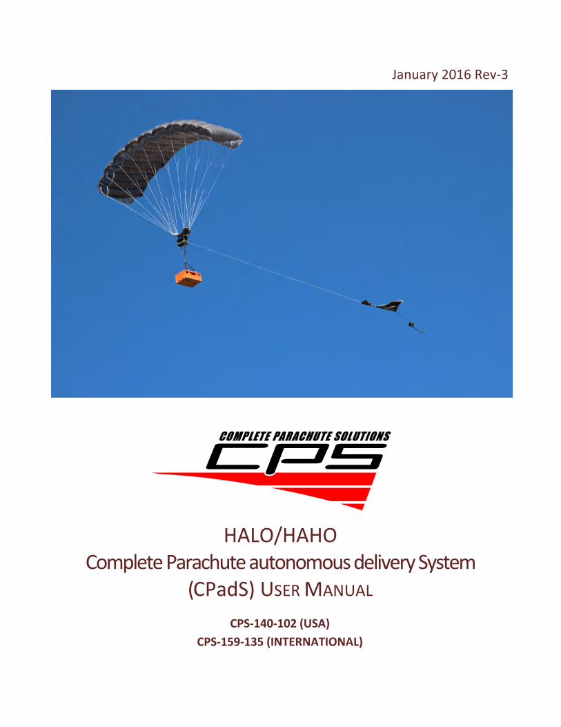
January 2016 Rev-3
HALO/HAHO Complete Parachute autonomous delivery System
(CPadS) USER MANUAL
CPS-140-102 (USA)
CPS-159-135 (INTERNATIONAL)
2 Warning and Disclaimer
Warning and Disclaimer
Dropping cargo from aircraft is a hazardous activity that can result in serious injury or death. Failure to follow all warning, instructions and required procedures may result in serious injury or death. Parachutes sometimes malfunction, even when they are properly designed, built, assembled, packed, maintained and used. The results of such malfunctions are sometimes serious injury or death. There are so many factors, both human and natural, beyond our control that we want you to clearly understand that by using or intending to use the Complete Parachute autonomous delivery System (CPadS), you are assuming a considerable risk of personal injury or death. If you are not willing to assume that risk, please return the system to the manufacturer and do not use it.
There are NO WARRANTIES which extend beyond the description of the parachutes in the manual and neither the seller nor any agent of the seller has made any affirmation of fact or promise with respect to the CPadS, including, but not limited to, the canopy system, airborne guidance unit and flight software, except those that appear therein. The liability of the seller is limited to the duty to replace defective parts found upon examination by the manufacturer to be defective in material or workmanship within 365 days after delivery and found not to have been caused by any accident, improper use, alteration, tampering, abuse or lack of care on the part of the purchaser.
3 Revision History
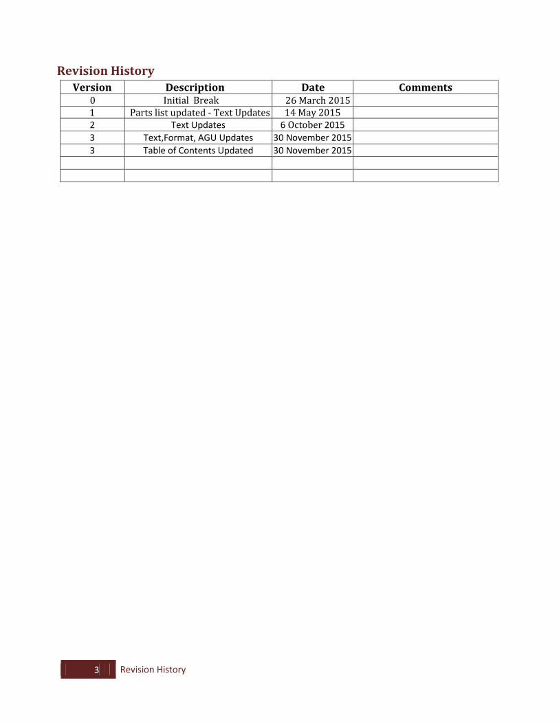
Revision History
Version Description Date Comments 0 Initial Break 26 March 2015 1 Parts list updated - Text Updates 14 May 2015 2 Text Updates 6 October 2015 3 Text,Format, AGU Updates 30 November 2015 3 Table of Contents Updated 30 November 2015
4 Table of Contents
Table of Contents Warning and Disclaimer ......................................................................................................................................... 2
Revision History ..................................................................................................................................................... 3
Table of Contents................................................................................................................................................... 4
List of Acronyms and Abbreviations ...................................................................................................................... 6
1.1. Scope ..................................................................................................................................................... 7
1.2. System Configurations ........................................................................................................................... 9
1.3. CPadS Point of Contact For System Support or Questions .................................................................. 10
1.4. Responsibilities and Cautions .............................................................................................................. 11
2. Parts List ....................................................................................................................................................... 12
3. Required Tools and Consumables for Packing and Rigging ......................................................................... 13
3.1. Consumables and Tools ....................................................................................................................... 13
4. Assembling the CPadS System ..................................................................................................................... 14
4.1. Orientation of the Canopy ................................................................................................................... 14
4.2. Attaching the Canopy to the Pack Tray ................................................................................................ 15
4.3. Attaching the Pack Tray to the AGU..................................................................................................... 19
4.4. Installing the Control Lines ................................................................................................................... 21
4.5. Deployment Bag and Cone Drogue Setup ........................................................................................... 25
4.6 Drogue Deployment Bag and Release-away Static Line Set Up............................................................ 31
5. Packing the CPadS ........................................................................................................................................ 37
5.1. Rigging the AGU ................................................................................................................................... 37
5.2. Flaking the Canopy ............................................................................................................................... 39
5.3. Packing the Canopy into the Deployment Bag ..................................................................................... 50
5.4 Place the Deployment Bag into Pack tray ............................................................................................ 58
5.5. Closing the Pack Tray ........................................................................................................................... 60
5.6. Stowing the Recovery Bag .................................................................................................................... 69
5.7. Packing the Cone Drogue ..................................................................................................................... 72
5.8. Securing the Drogue to the Pack Tray .................................................................................................. 80
6. Rigging the CPadS to the Payload ................................................................................................................ 90
6.1. Attaching the 4-Point Suspension Swivel Harness ............................................................................... 90
6.2. Securing the AGU to the Payload ......................................................................................................... 91
7. Mission Planning for CPadS Airdrops ........................................................................................................... 92
5 Table of Contents
8. System Maintenance ................................................................................................................................... 94
8.1. Shelf Life............................................................................................................................................... 94
8.2. Inspection Cycle ................................................................................................................................... 94
8.3. Software Updates ................................................................................................................................ 94
8.4. Battery Charging .................................................................................................................................. 95
9. Instructions, Quick Start and Troubleshooting For The CPadS AGU .......................................................... 97
9.1. Operator Instructions for the CPadS AGU ........................................................................................... 97
9.2. Quick Start Guide: PROGRAMMING THE CPadS AGU ........................................................................ 109
9.3. Troubleshooting Procedures for CPadS AGU ..................................................................................... 112
10. Addenda ................................................................................................................................................. 117
10.1. PD Slink Installation Instructions ................................................................................................... 117
10.2. Assembly , Packing and Payload Rigger Checks ............................................................................. 118
6 List of Acronyms and Abbreviations
List of Acronyms and Abbreviations
AGU Airborne Guidance Unit CPadS Complete Parachute autonomous delivery System
GN&C Guidance, Navigation & Control GPS Global Positioning System HALO High Altitude Low Opening lb Pounds ULW Ultra-Light Weight MSL Mean Sea Level POC Point of Contact sq ft Square Foot
7 Introduction
1. Introduction
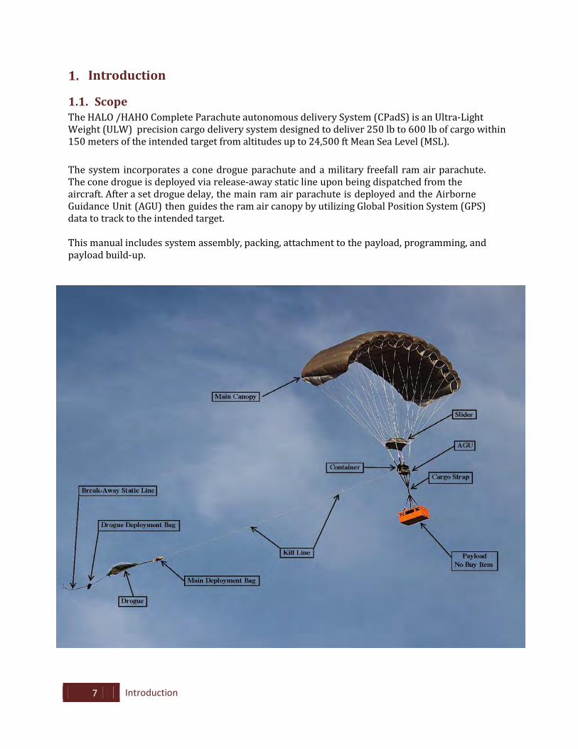
1.1. Scope The HALO /HAHO Complete Parachute autonomous delivery System (CPadS) is an Ultra-Light Weight (ULW) precision cargo delivery system designed to deliver 250 lb to 600 lb of cargo within 150 meters of the intended target from altitudes up to 24,500 ft Mean Sea Level (MSL). The system incorporates a cone drogue parachute and a military freefall ram air parachute. The cone drogue is deployed via release-away static line upon being dispatched from the aircraft. After a set drogue delay, the main ram air parachute is deployed and the Airborne Guidance Unit (AGU) then guides the ram air canopy by utilizing Global Position System (GPS) data to track to the intended target.
This manual includes system assembly, packing, attachment to the payload, programming, and payload build-up.
8 Introduction
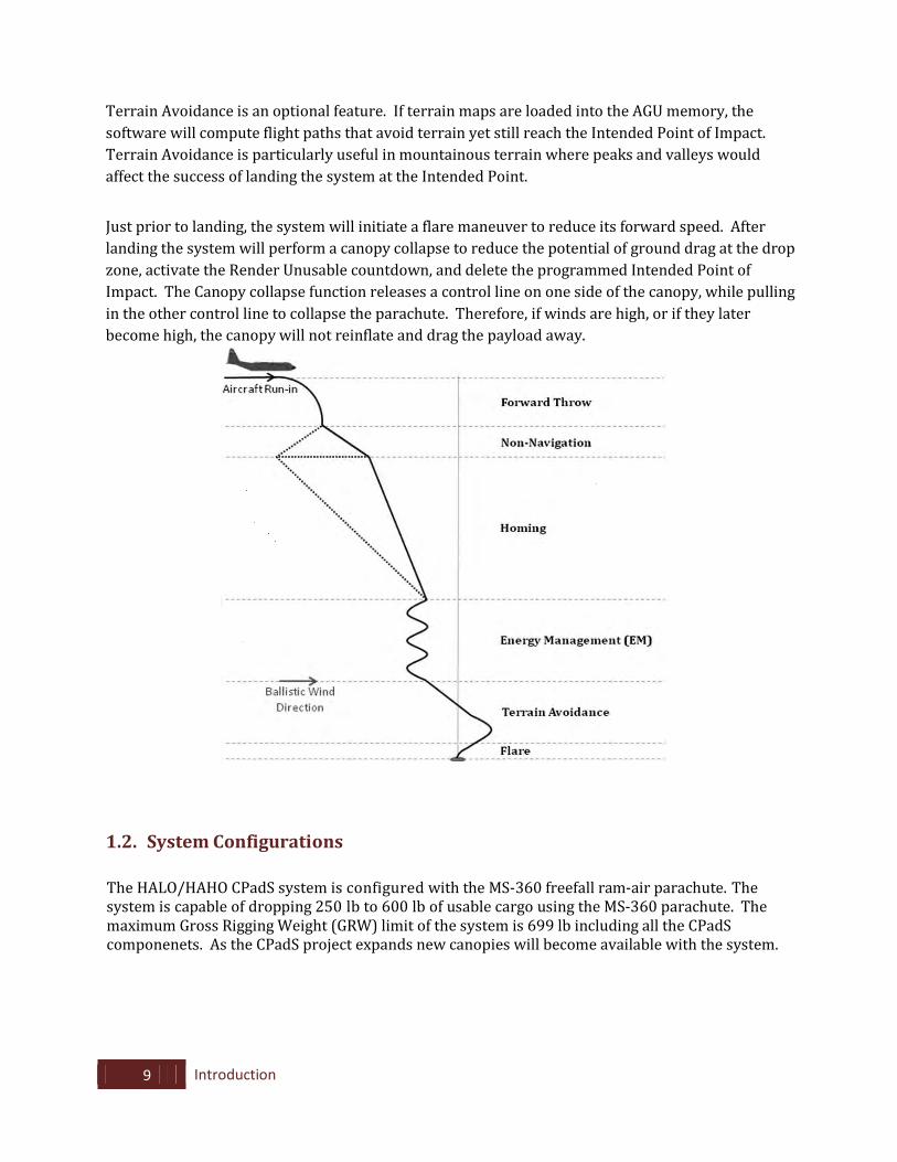
CPadS System and Flight Software The CPadS system has six major stages of flight: Programmable Ballistic Transition (HALO/HAHO), Non-Navigation, Homing, Energy Management (EM), and Final Approach (with optional Terrain Avoidance). The ballistic transition phase is where the deployment sequence occurs and results in a fully inflated ram air parachute. Upon dispatch from the aircraft via a Release-Away Static Line (RASL), a cone drogue parachute is immediately deployed. The duration of drogue fall time/altitude is fully programmable and set by the operator per the mission requirements. The minimum drogue fall time is 6 seconds to allow clearance from the aircraft and initialization of the system. A short drogue fall time will result in a HAHO capability. Alternatively, the operator can program the system for extended rapid descent under drogue by programming the time under drogue/opening altitude accordingly. A HALO capability is realized under this scenario to rapidly clear the airspace and deliver the payload quickly with minimal chance for detection. The altitude based setting requires GPS lock to function. GPS lock is not required for CPadS prior to drop, typically acquiring lock within 30 seconds after deployment if the aircraft is not fitted with a GPS retransmission kit. The CPadS will transition from drogue to the main parachute when either the time since deployment has been met, OR when the GPS lock is achieved and the programmed altitude is reached. Whichever occurs first will trigger the transition sequence. Therefore setting the drogue fall time to the expected altitude value will always ensure transition to the main parachute even if GPS lock has not yet been achieved. After transitioning to the main parachute, and since the parachute deployment is variable, the flight software will monitor on-board sensors to ensure the parachute is fully open prior to navigating. This amount of time in the Non-Navigation phase can vary from 10 to 60 seconds. GPS lock is required for this assessment. If GPS lock is not yet achieved, CPadS will command a slow turn while waiting for GPS to lock. Once GPS lock is achieved and the assessment of system status is made, navigation can occur. Upon initiation of navigation, the system will begin “homing” directly to the Energy Management (EM) location. EM is a computed fixed position located upwind of the Intended Point of Impact. The CPadS will manage energy, continually adjusting as wind conditions change while preparing for Final Approach and Landing. The extent or initiation of the homing phase and EM phase depends on the release point’s distance relative to the Intended Point of Impact. Final Approach initiates at 1,000 ft above the target altitude. During this time the system is continuously calculating a variety of projected flight paths and weighing the consequences of each with regards to distance from Intended Impact Point (horizontal and vertical) and landing into the wind.
9 Introduction
Terrain Avoidance is an optional feature. If terrain maps are loaded into the AGU memory, the software will compute flight paths that avoid terrain yet still reach the Intended Point of Impact. Terrain Avoidance is particularly useful in mountainous terrain where peaks and valleys would affect the success of landing the system at the Intended Point. Just prior to landing, the system will initiate a flare maneuver to reduce its forward speed. After landing the system will perform a canopy collapse to reduce the potential of ground drag at the drop zone, activate the Render Unusable countdown, and delete the programmed Intended Point of Impact. The Canopy collapse function releases a control line on one side of the canopy, while pulling in the other control line to collapse the parachute. Therefore, if winds are high, or if they later become high, the canopy will not reinflate and drag the payload away.
1.2. System Configurations
The HALO/HAHO CPadS system is configured with the MS-360 freefall ram-air parachute. The system is capable of dropping 250 lb to 600 lb of usable cargo using the MS-360 parachute. The maximum Gross Rigging Weight (GRW) limit of the system is 699 lb including all the CPadS componenets. As the CPadS project expands new canopies will become available with the system.

10 Introduction
1.3. CPadS Point of Contact For System Support or Questions
[email protected] Tel.: +1.386.736.3862 COMPLETE PARACHUTE SOLUTIONS, INC. 1326 EAST INTERNATIONAL SPEEDWAY BLVD. SUITE 7 DELAND, FLORIDA 32724 USA www.cpsworld.com
11 Introduction
1.4. Responsibilities and Cautions The HALO/HAHO CPadS is designed for use by trained, qualified operators only. The instruction manual is intended to be used without deviation to ensure optimum system performance. It is important that personnel involved with the use and maintenance of the HALO/HAHO CPadS read and understand this manual before proceeding with its use. Wamore Inc. and Complete Parachute Solutions, Inc. assume no responsibility for the incorrect use, packing, rigging, or programming of the HALO/HAHO CPadS.
12 Parts List
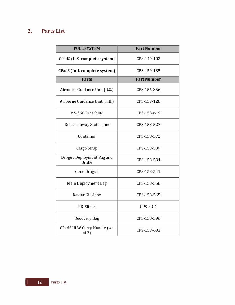
2. Parts List
FULL SYSTEM Part Number
CPadS (U.S. complete system) CPS-140-102
CPadS (Intl. complete system) CPS-159-135
Parts Part Number
Airborne Guidance Unit (U.S.) CPS-156-356
Airborne Guidance Unit (Intl.) CPS-159-128
MS-360 Parachute CPS-158-619
Release-away Static Line CPS-158-527
Container CPS-158-572
Cargo Strap CPS-158-589
Drogue Deployment Bag and Bridle CPS-158-534
Cone Drogue CPS-158-541
Main Deployment Bag CPS-158-558
Kevlar Kill-Line CPS-158-565
PD-Slinks CPS-SR-1
Recovery Bag CPS-158-596
CPadS ULW Carry Handle (set of 2) CPS-158-602
13 Required Tools and Consumables for Packing and Rigging
3. Required Tools and Consumables for Packing and Rigging
3.1. Consumables and Tools
A. Ticket 5 or 8/7 Thread (or equivalent 30-31 lb tensile strength) P/N: CPS-159-241
NSN: 8310-00-917-3945
B. Ticket 3 or 8/4 Thread (or equivalent 15-16 lb tensile strength) P/N: CPS-161-282 NSN: 8310-01-279-6073 C. Super Tack (50 lb tensile strength or greater) P/N: CPS-157-223
MIL-T-43435
D. PD-Slinks P/N: CPS-SR-1
E. Heavy Weight Retainer Bands P/N: CPS-161-312 NSN: 1670-00-568-0323
F. Black Tandem Tube Stoes
P/N: CPS-TUBE STOE-TB
G. Paper Tape P/N: CPS-159-234 NSN: 7510-00-680-2395 H. Knife I. Adjustable Wrench J. Pull-Up Cords (2ea. - Bright colors / 38” long ±)
14 Assembling the CPadS
4. Assembling the CPadS System
4.1. Orientation of the Canopy
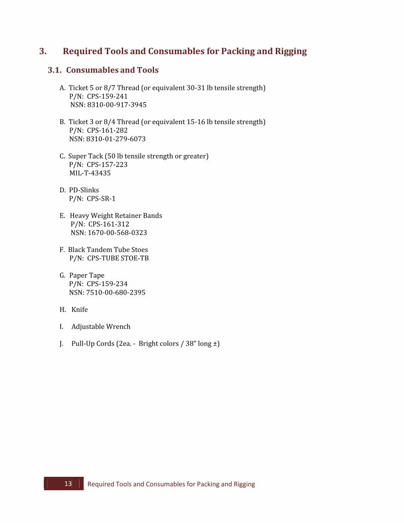
4.1.1. Hang the canopy (as shown) or lay the canopy on the ground with the nose facing down and the left and right riser groups separated.
NOTE: Ensure before you proceed
to complete a continuity check of the canopy according to your unit SOP’s.
NOTE: Before proceeding with the
assembly and packing of the CPadS print off a copy of the RIGGER CHECK packing and assembly sheet in the back of this manual.
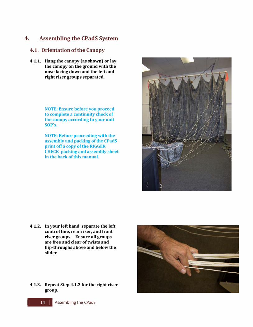
4.1.2. In your left hand, separate the left
control line, rear riser, and front riser groups. Ensure all groups are free and clear of twists and flip-throughs above and below the slider
4.1.3. Repeat Step 4.1.2 for the right riser
group.
15 Assembling the CPadS
4.2. Attaching the Canopy to the Pack Tray
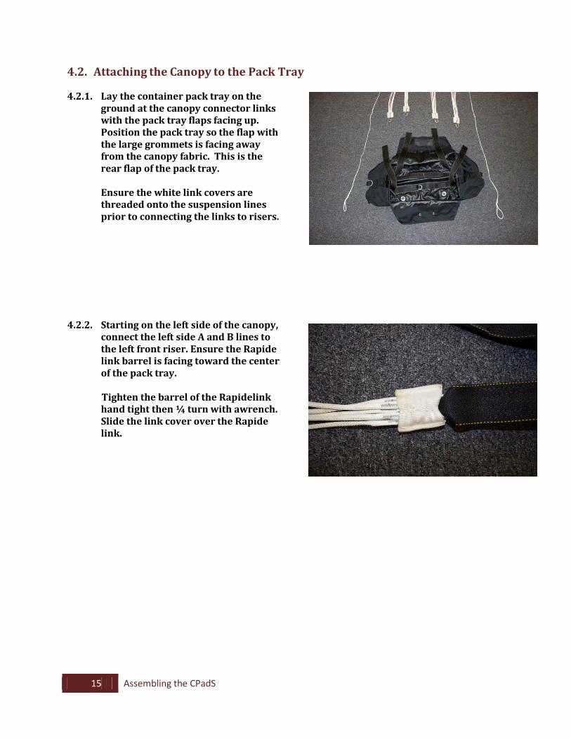
4.2.1. Lay the container pack tray on the ground at the canopy connector links with the pack tray flaps facing up. Position the pack tray so the flap with the large grommets is facing away from the canopy fabric. This is the rear flap of the pack tray.
Ensure the white link covers are
threaded onto the suspension lines prior to connecting the links to risers.
4.2.2. Starting on the left side of the canopy,
connect the left side A and B lines to the left front riser. Ensure the Rapide link barrel is facing toward the center of the pack tray.
Tighten the barrel of the Rapidelink hand tight then ¼ turn with awrench. Slide the link cover over the Rapide link.
16 Assembling the CPadS
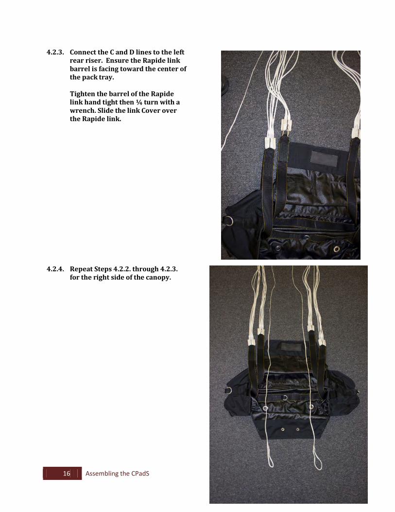
4.2.3. Connect the C and D lines to the left rear riser. Ensure the Rapide link barrel is facing toward the center of the pack tray.
Tighten the barrel of the Rapide
link hand tight then ¼ turn with a wrench. Slide the link Cover over the Rapide link.
4.2.4. Repeat Steps 4.2.2. through 4.2.3. for the right side of the canopy.
17 Assembling the CPadS
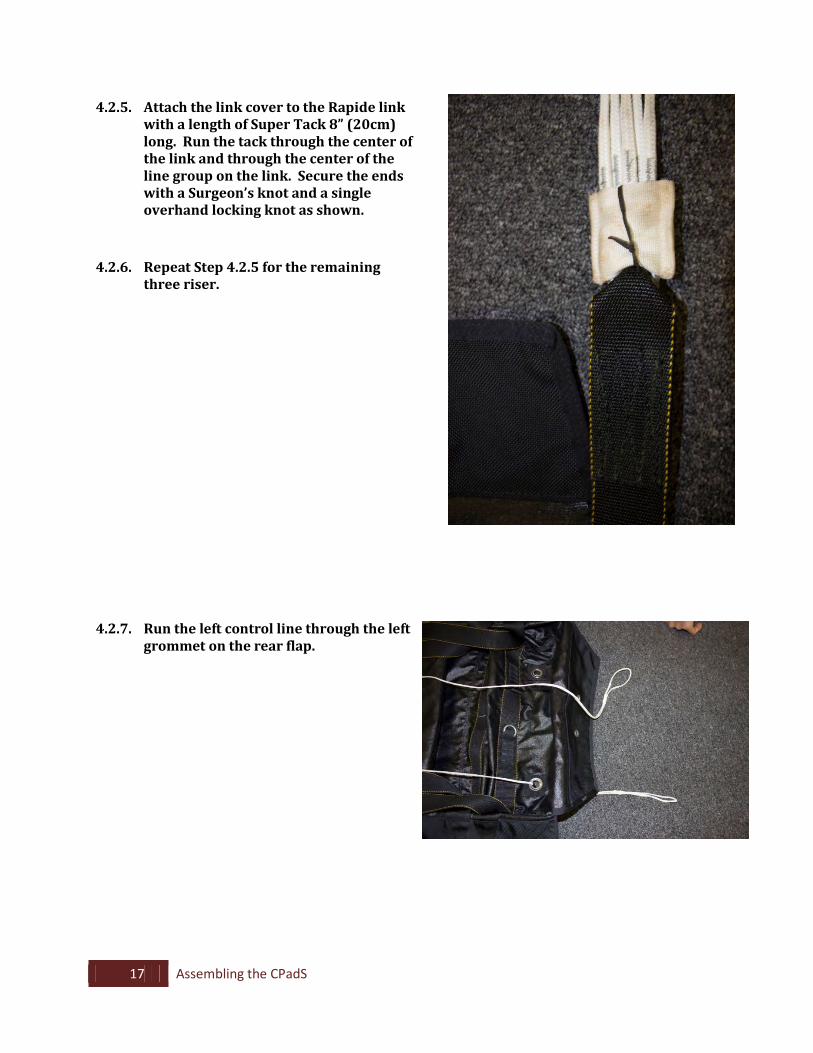
4.2.5. Attach the link cover to the Rapide link with a length of Super Tack 8” (20cm) long. Run the tack through the center of the link and through the center of the line group on the link. Secure the ends with a Surgeon’s knot and a single overhand locking knot as shown.
4.2.6. Repeat Step 4.2.5 for the remaining three riser.
4.2.7. Run the left control line through the left grommet on the rear flap.
18 Assembling the CPadS
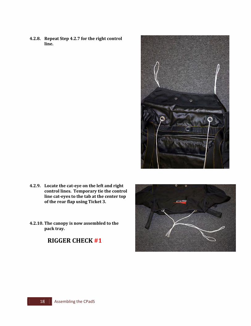
4.2.8. Repeat Step 4.2.7 for the right control
line.
4.2.9. Locate the cat-eye on the left and right
control lines. Temporary tie the control line cat-eyes to the tab at the center top of the rear flap using Ticket 3.
4.2.10. The canopy is now assembled to the pack tray.
RIGGER CHECK #1
19 Assembling the CPadS
4.3. Attaching the Pack Tray to the AGU
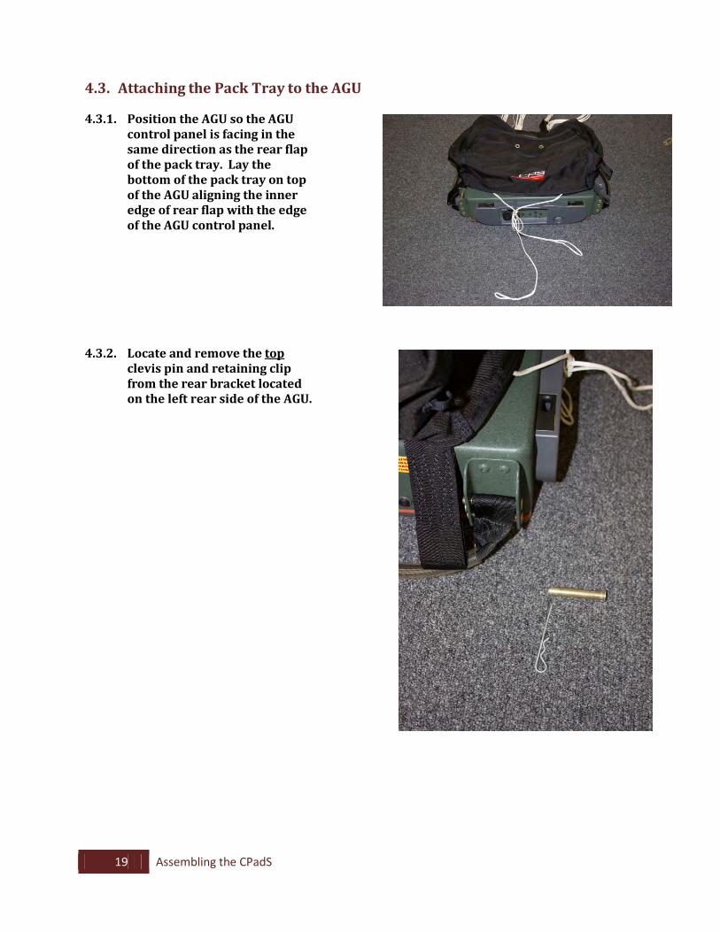
4.3.1. Position the AGU so the AGU control panel is facing in the same direction as the rear flap of the pack tray. Lay the bottom of the pack tray on top of the AGU aligning the inner edge of rear flap with the edge of the AGU control panel.
4.3.2. Locate and remove the top
clevis pin and retaining clip from the rear bracket located on the left rear side of the AGU.
20 Assembling the CPadS
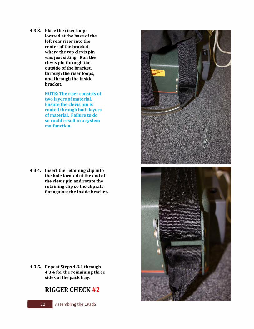
4.3.3. Place the riser loops located at the base of the left rear riser into the center of the bracket where the top clevis pin was just sitting. Run the clevis pin through the outside of the bracket, through the riser loops, and through the inside bracket.
NOTE: The riser consists of two layers of material. Ensure the clevis pin is routed through both layers of material. Failure to do so could result in a system malfunction.
4.3.4. Insert the retaining clip into the hole located at the end of the clevis pin and rotate the retaining clip so the clip sits flat against the inside bracket.
4.3.5. Repeat Steps 4.3.1 through 4.3.4 for the remaining three sides of the pack tray.
RIGGER CHECK #2
21 Assembling the CPadS
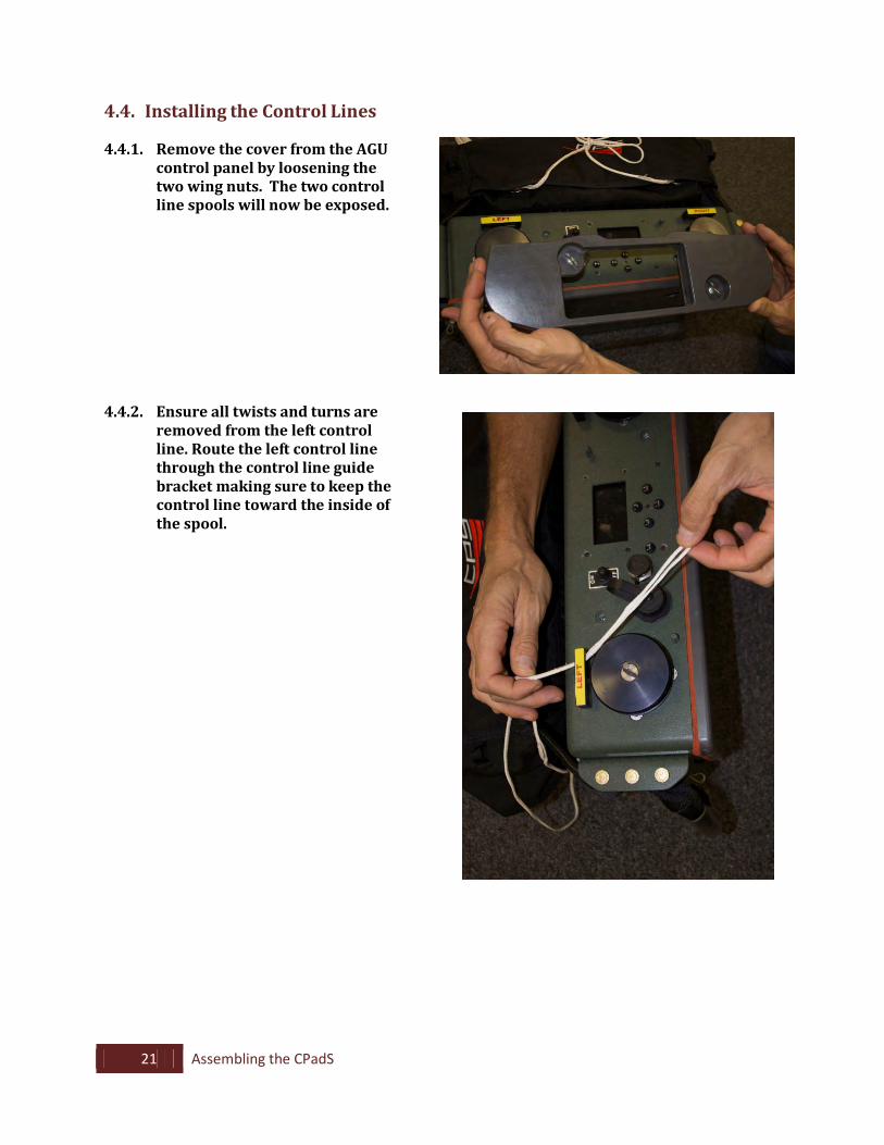
4.4. Installing the Control Lines
4.4.1. Remove the cover from the AGU control panel by loosening the two wing nuts. The two control line spools will now be exposed.
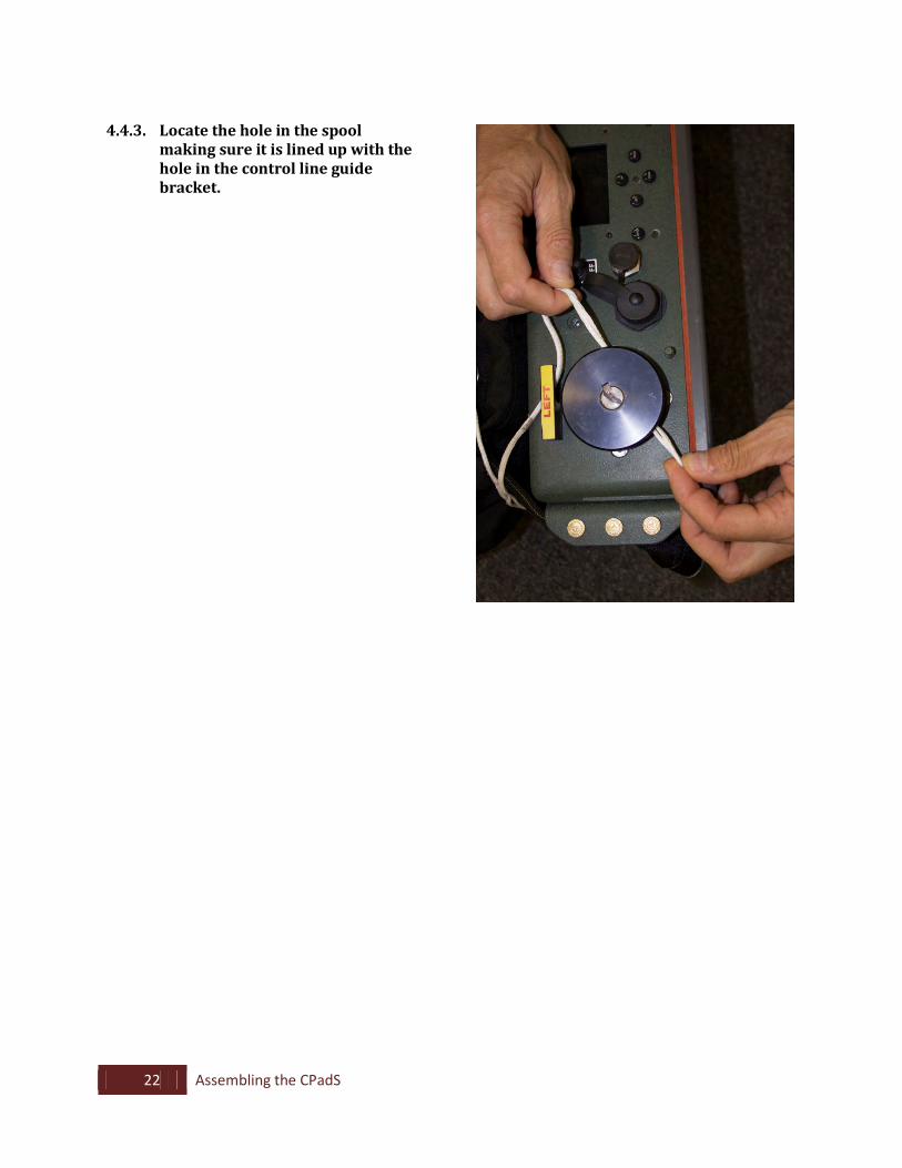
4.4.2. Ensure all twists and turns are
removed from the left control line. Route the left control line through the control line guide bracket making sure to keep the control line toward the inside of the spool.
22 Assembling the CPadS
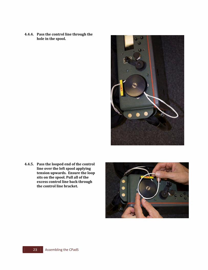
4.4.3. Locate the hole in the spool
making sure it is lined up with the hole in the control line guide bracket.
23 Assembling the CPadS
4.4.4. Pass the control line through the hole in the spool.
4.4.5. Pass the looped end of the control
line over the left spool applying tension upwards. Ensure the loop sits on the spool. Pull all of the excess control line back through the control line bracket.

24 Assembling the CPadS
4.4.6. Repeat Steps 4.4.2 through 4.4.5
for the right control line.
4.4.7. Reattach the AGU control panel cover and secure the two wing nuts by hand tightening.
25 Assembling the CPadS
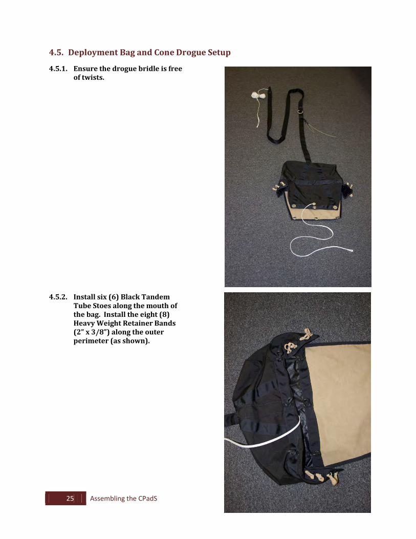
4.5. Deployment Bag and Cone Drogue Setup
4.5.1. Ensure the drogue bridle is free of twists.
4.5.2. Install six (6) Black Tandem Tube Stoes along the mouth of the bag. Install the eight (8) Heavy Weight Retainer Bands (2” x 3/8”) along the outer perimeter (as shown).
26 Assembling the CPadS
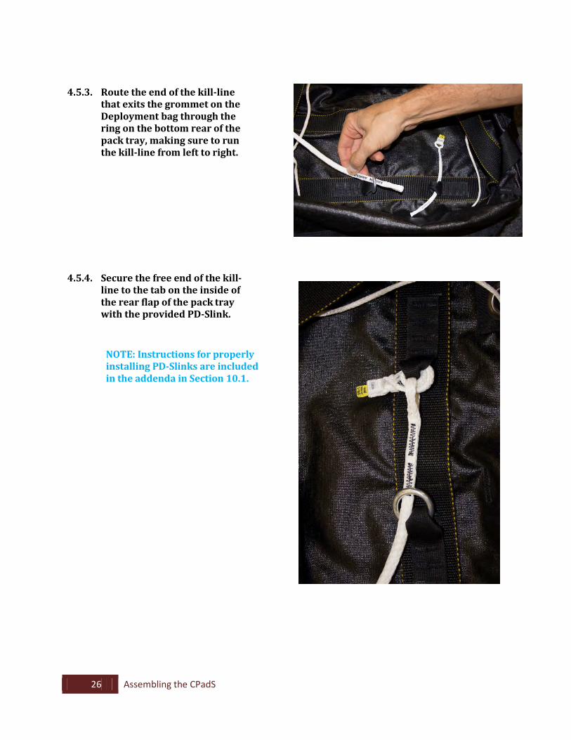
4.5.3. Route the end of the kill-line that exits the grommet on the Deployment bag through the ring on the bottom rear of the pack tray, making sure to run the kill-line from left to right.
4.5.4. Secure the free end of the kill-line to the tab on the inside of the rear flap of the pack tray with the provided PD-Slink.
NOTE: Instructions for properly installing PD-Slinks are included in the addenda in Section 10.1.
27 Assembling the CPadS
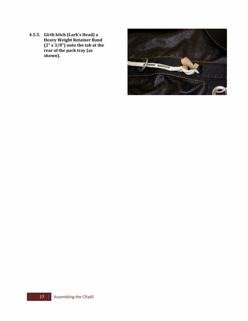
4.5.5. Girth hitch (Lark’s Head) a
Heavy Weight Retainer Band (2” x 3/8”) onto the tab at the rear of the pack tray (as shown).
28 Assembling the CPadS
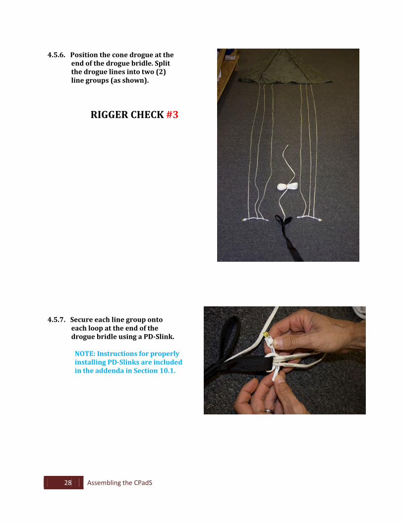
4.5.6. Position the cone drogue at the end of the drogue bridle. Split the drogue lines into two (2) line groups (as shown).
RIGGER CHECK #3
4.5.7. Secure each line group onto each loop at the end of the drogue bridle using a PD-Slink.
NOTE: Instructions for properly installing PD-Slinks are included in the addenda in Section 10.1.
29 Assembling the CPadS
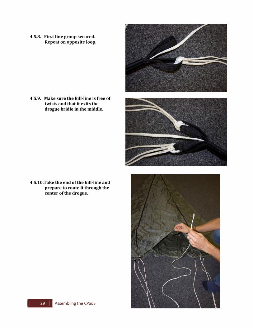
4.5.8. First line group secured.
Repeat on opposite loop.
4.5.9. Make sure the kill-line is free of twists and that it exits the drogue bridle in the middle.
4.5.10.Take the end of the kill-line and prepare to route it through the center of the drogue.
30 Assembling the CPadS
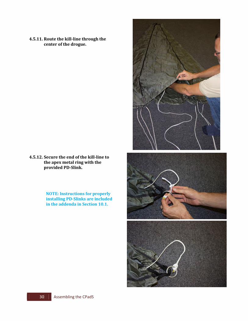
4.5.11. Route the kill-line through the center of the drogue.
4.5.12. Secure the end of the kill-line to the apex metal ring with the provided PD-Slink.
NOTE: Instructions for properly installing PD-Slinks are included in the addenda in Section 10.1.
31 Assembling the CPadS
4.6 Drogue Deployment Bag and Release-away Static Line Set Up
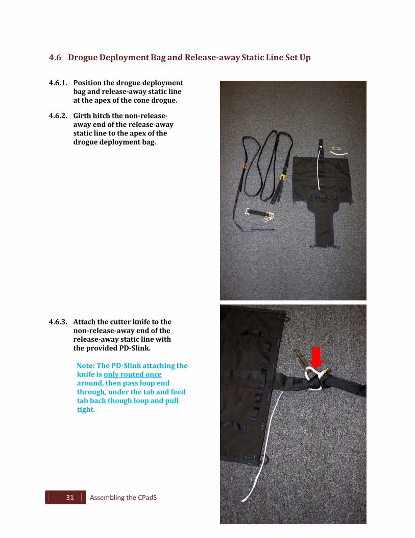
4.6.1. Position the drogue deployment bag and release-away static line at the apex of the cone drogue.
4.6.2. Girth hitch the non-release-
away end of the release-away static line to the apex of the drogue deployment bag.
4.6.3. Attach the cutter knife to the non-release-away end of the release-away static line with the provided PD-Slink.
Note: The PD-Slink attaching the
knife is only routed once around, then pass loop end through, under the tab and feed tab back though loop and pull tight.
32 Assembling the CPadS
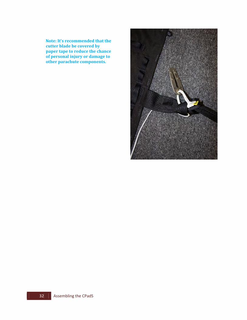
Note: It’s recommended that the cutter blade be covered by paper tape to reduce the chance of personal injury or damage to other parachute components.
33 Assembling the CPadS
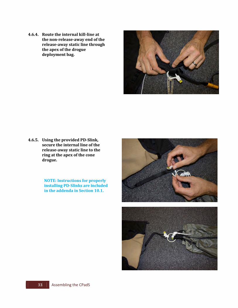
4.6.4. Route the internal kill-line at
the non-release-away end of the release-away static line through the apex of the drogue deployment bag.
4.6.5. Using the provided PD-Slink, secure the internal line of the release-away static line to the ring at the apex of the cone drogue.
NOTE: Instructions for properly installing PD-Slinks are included in the addenda in Section 10.1.
34 Assembling the CPadS
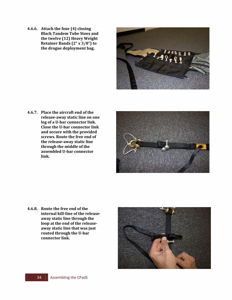
4.6.6. Attach the four (4) closing Black Tandem Tube Stoes and the twelve (12) Heavy Weight Retainer Bands (2” x 3/8”) to the drogue deployment bag.
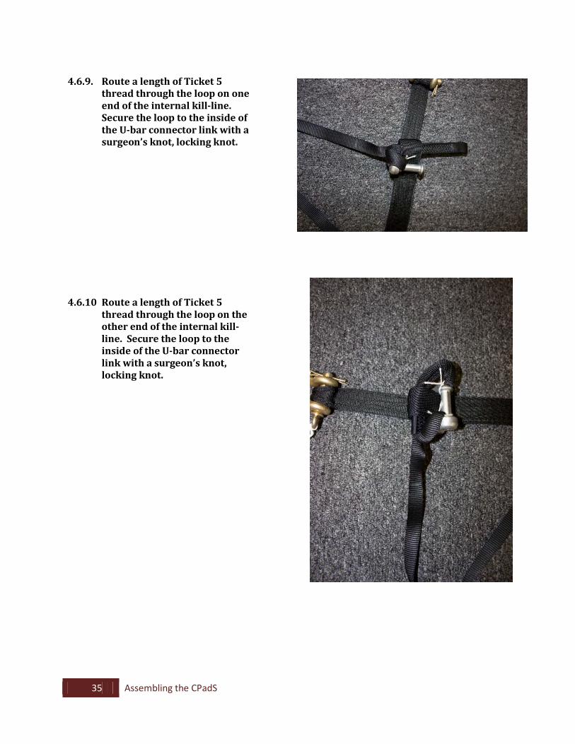
4.6.7. Place the aircraft end of the
release-away static line on one leg of a U-bar connector link. Close the U-bar connector link and secure with the provided screws. Route the free end of the release-away static line through the middle of the assembled U-bar connector link.
4.6.8. Route the free end of the internal kill-line of the release-away static line through the loop at the end of the release-away static line that was just routed through the U-bar connector link.
35 Assembling the CPadS
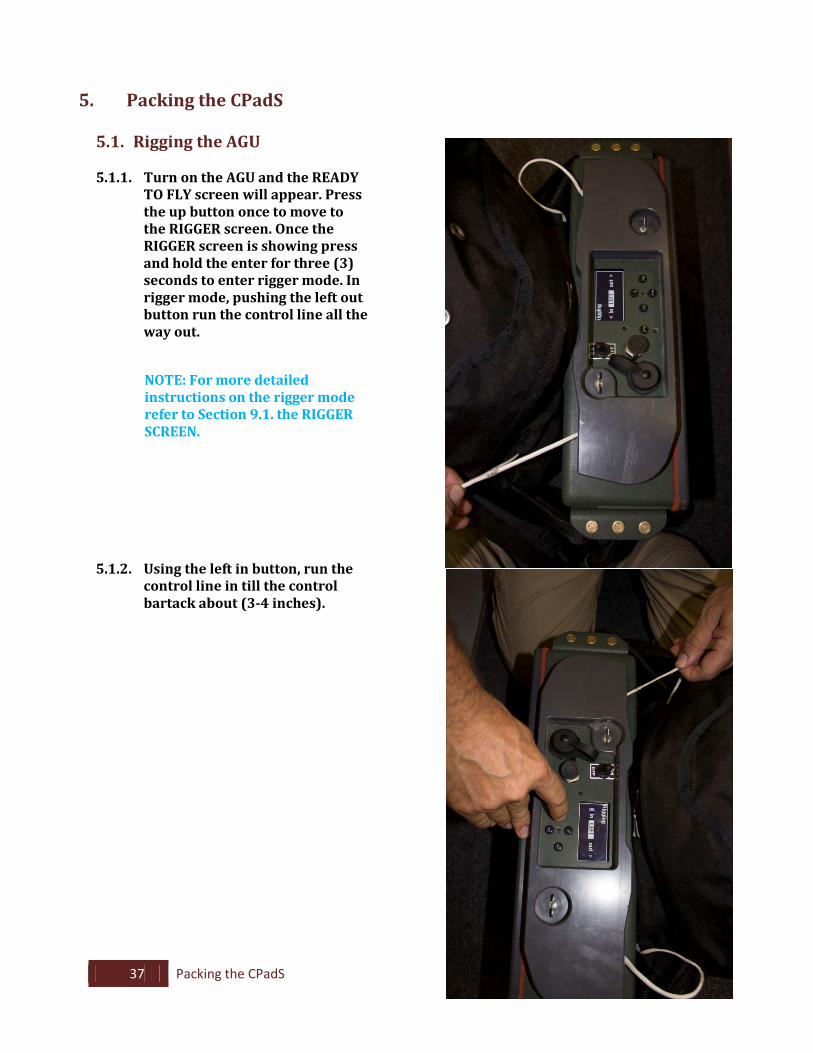
4.6.9. Route a length of Ticket 5
thread through the loop on one end of the internal kill-line. Secure the loop to the inside of the U-bar connector link with a surgeon’s knot, locking knot.
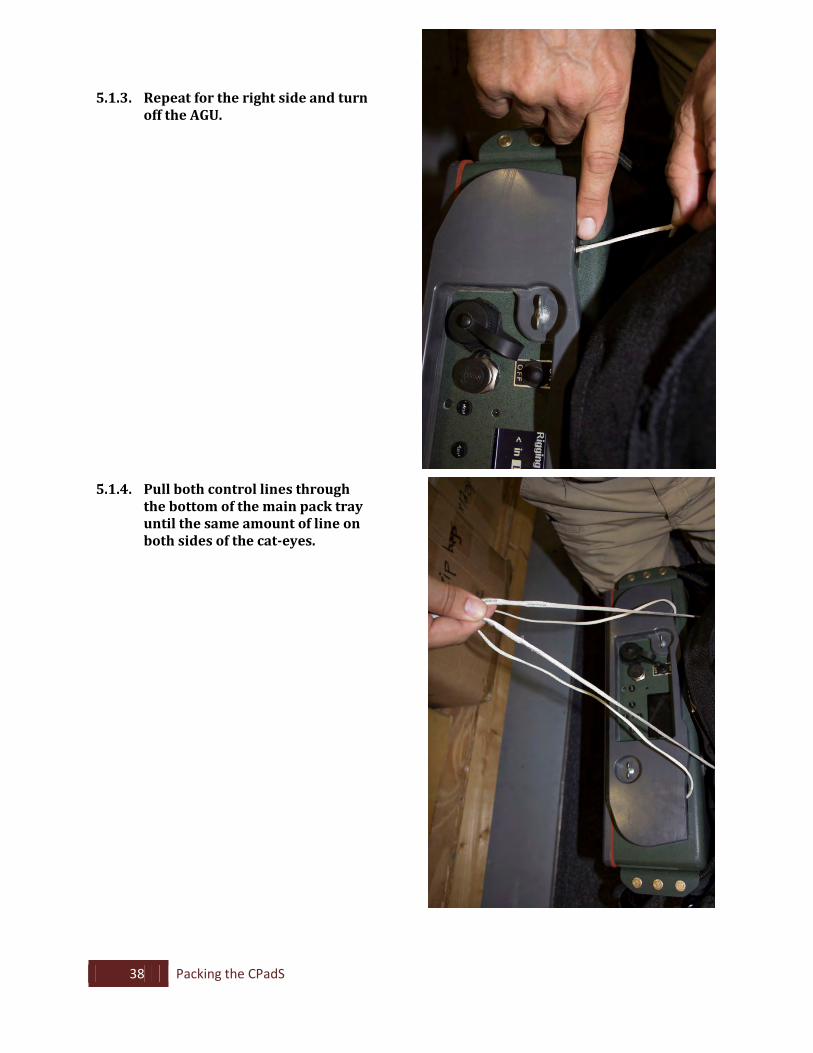
4.6.10 Route a length of Ticket 5 thread through the loop on the other end of the internal kill-line. Secure the loop to the inside of the U-bar connector link with a surgeon’s knot, locking knot.

36 Assembling the CPadS
4.6.11. Position the static line with the grommet facing upwards. S-fold the excess internal kill-line on top of the static line. Route one Heavy Weight Retainer band (2” x 3/8”) around the static line and secure the lower section of the S-folded internal line to the static line.
4.6.12. Repeat Step 4.6.10 for the top section of the S-folded internal kill-line.
4.6.13. Place a G-13 clevis on the free
end of the release-away static line.
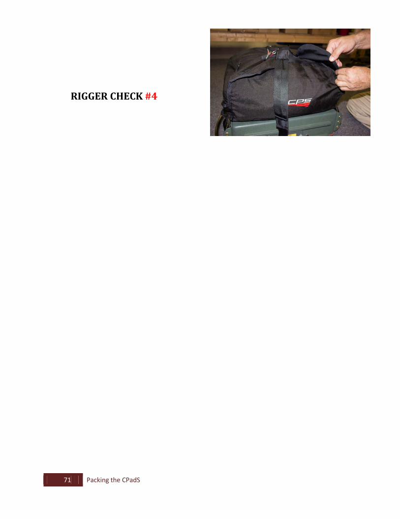
RIGGER CHECK #4
37 Packing the CPadS
5. Packing the CPadS 5.1. Rigging the AGU
5.1.1. Turn on the AGU and the READY
TO FLY screen will appear. Press the up button once to move to the RIGGER screen. Once the RIGGER screen is showing press and hold the enter for three (3) seconds to enter rigger mode. In rigger mode, pushing the left out button run the control line all the way out.
NOTE: For more detailed instructions on the rigger mode refer to Section 9.1. the RIGGER SCREEN.
5.1.2. Using the left in button, run the control line in till the control bartack about (3-4 inches).
38 Packing the CPadS
5.1.3. Repeat for the right side and turn off the AGU.
5.1.4. Pull both control lines through the bottom of the main pack tray until the same amount of line on both sides of the cat-eyes.
39 Packing the CPadS
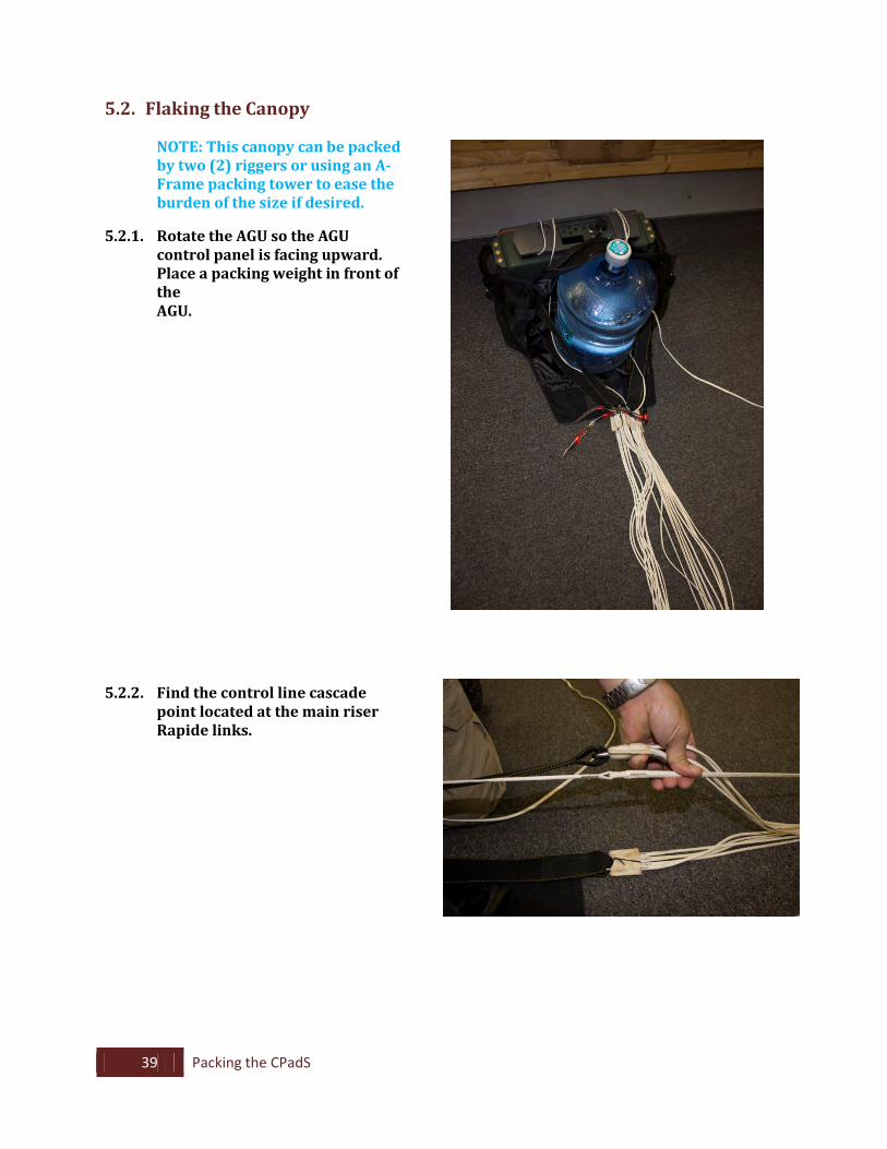
5.2. Flaking the Canopy
NOTE: This canopy can be packed by two (2) riggers or using an A- Frame packing tower to ease the burden of the size if desired.
5.2.1. Rotate the AGU so the AGU
control panel is facing upward. Place a packing weight in front of the AGU.
5.2.2. Find the control line cascade point located at the main riser Rapide links.
40 Packing the CPadS
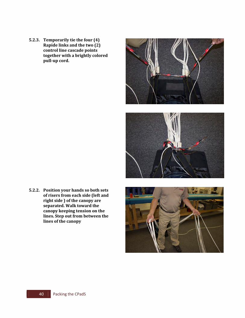
5.2.3. Temporarily tie the four (4)
Rapide links and the two (2) control line cascade points together with a brightly colored pull-up cord.
5.2.2. Position your hands so both sets
of risers from each side (left and right side ) of the canopy are separated. Walk toward the canopy keeping tension on the lines. Step out from between the lines of the canopy
41 Packing the CPadS
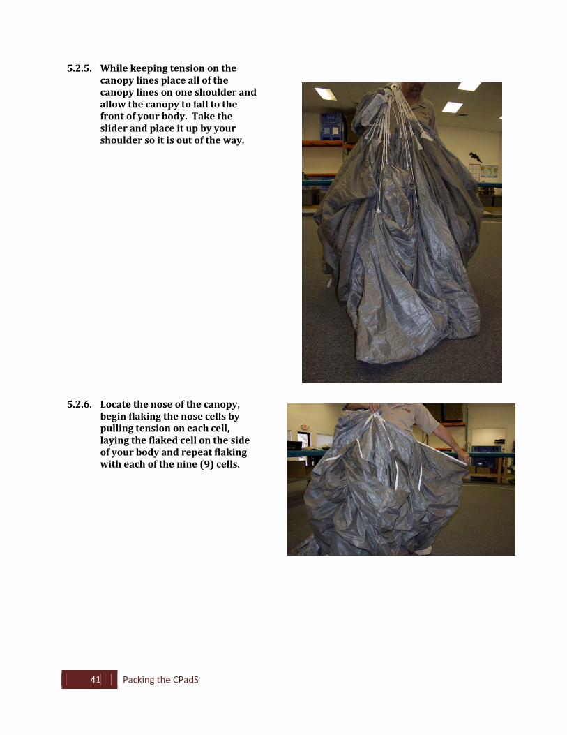
5.2.5. While keeping tension on the canopy lines place all of the canopy lines on one shoulder and allow the canopy to fall to the front of your body. Take the slider and place it up by your shoulder so it is out of the way.
5.2.6. Locate the nose of the canopy, begin flaking the nose cells by pulling tension on each cell, laying the flaked cell on the side of your body and repeat flaking with each of the nine (9) cells.
42 Packing the CPadS
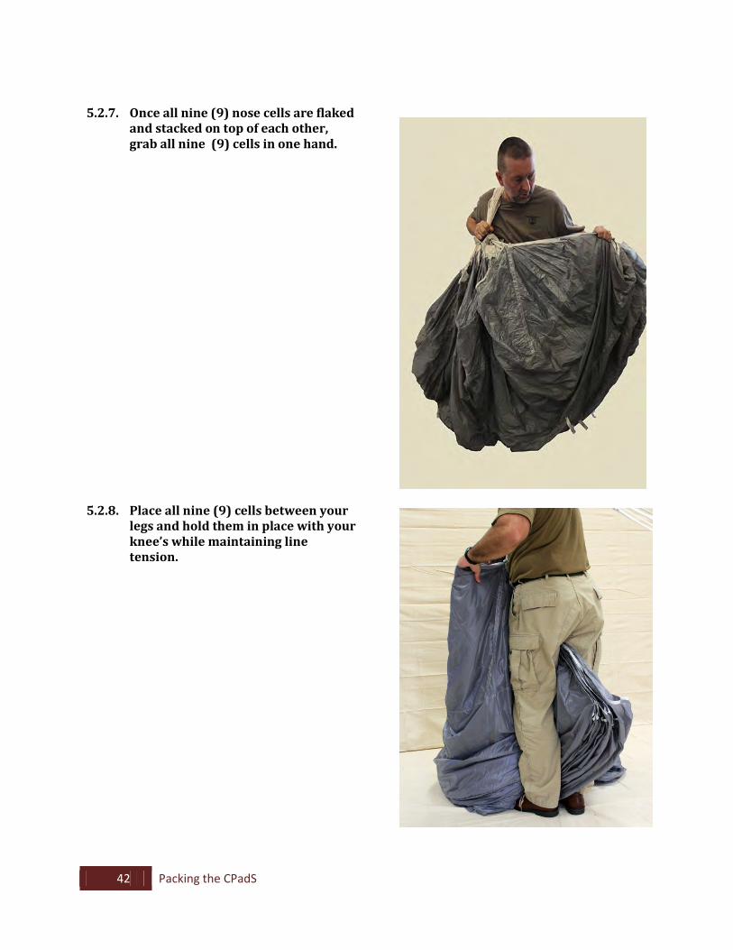
5.2.7. Once all nine (9) nose cells are flaked
and stacked on top of each other, grab all nine (9) cells in one hand.
5.2.8. Place all nine (9) cells between your
legs and hold them in place with your knee’s while maintaining line tension.
43 Packing the CPadS
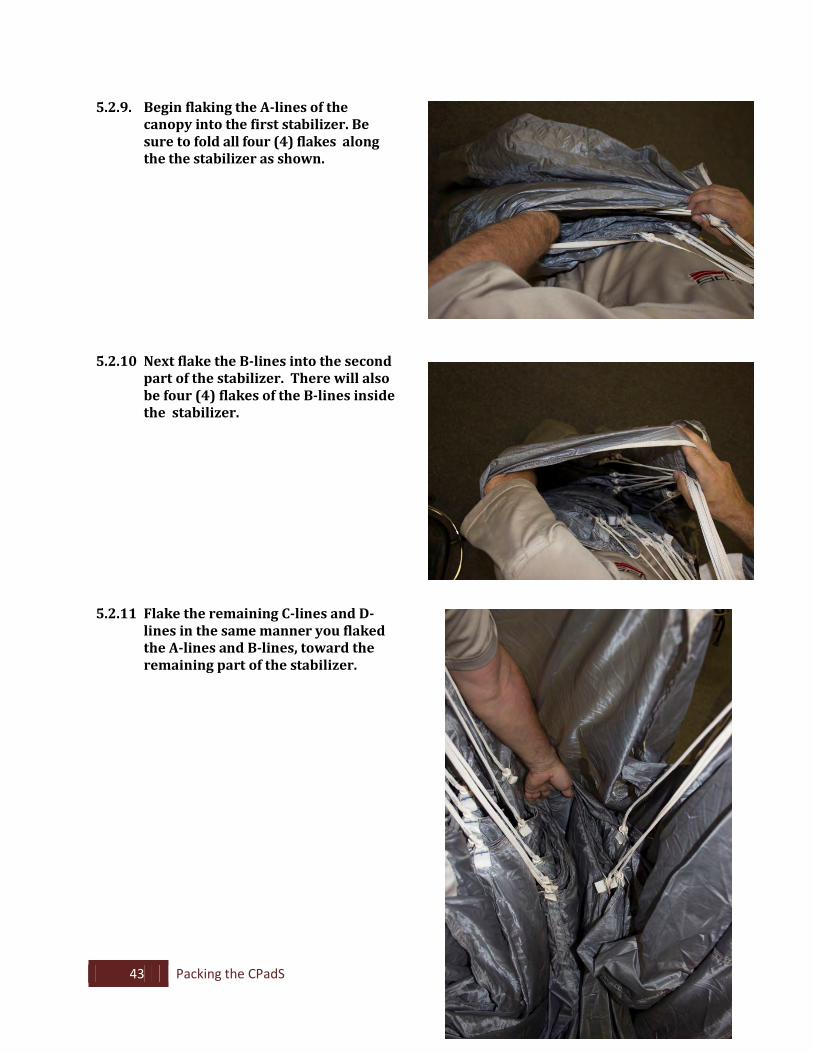
5.2.9. Begin flaking the A-lines of the canopy into the first stabilizer. Be sure to fold all four (4) flakes along the the stabilizer as shown.
5.2.10 Next flake the B-lines into the second part of the stabilizer. There will also be four (4) flakes of the B-lines inside the stabilizer.
5.2.11 Flake the remaining C-lines and D- lines in the same manner you flaked the A-lines and B-lines, toward the remaining part of the stabilizer.
44 Packing the CPadS
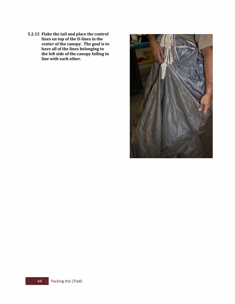
5.2.12 Flake the tail and place the control
lines on top of the D-lines in the center of the canopy. The goal is to have all of the lines belonging to the left side of the canopy falling in line with each other.
45 Packing the CPadS
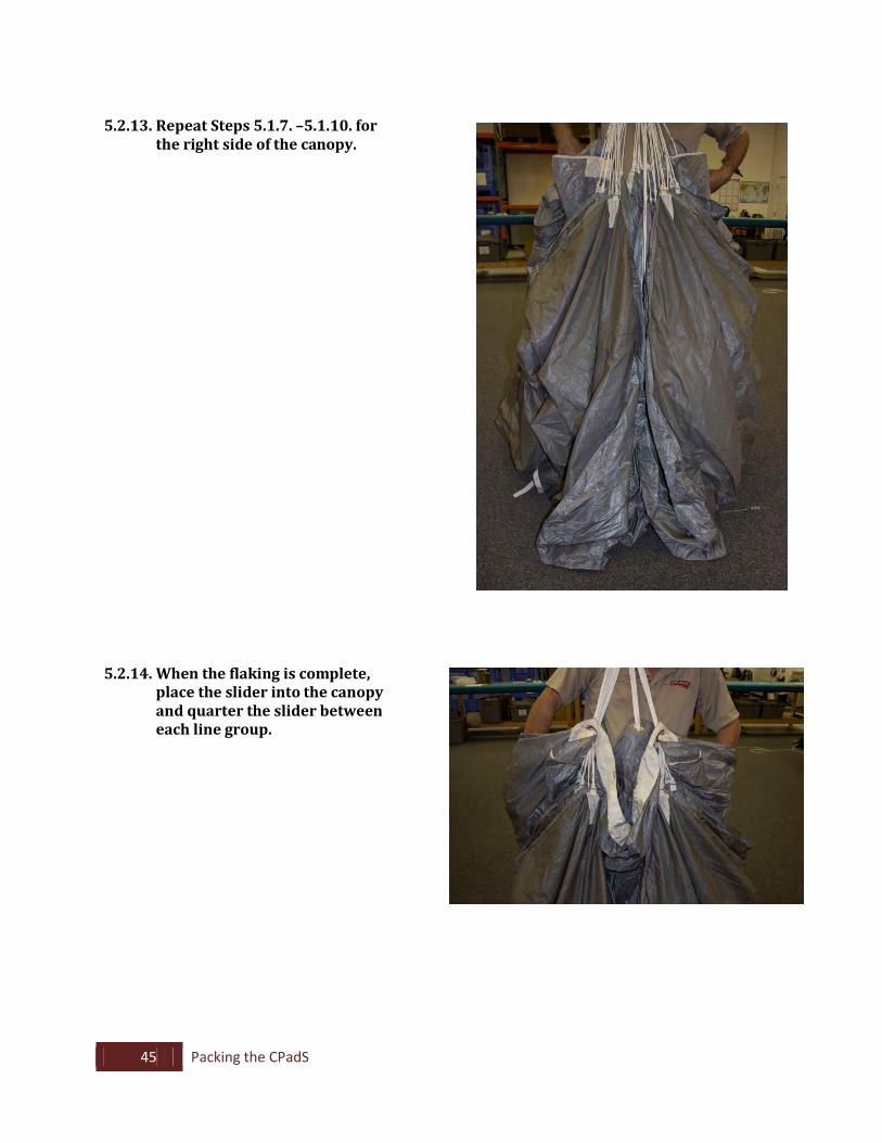
5.2.13. Repeat Steps 5.1.7. –5.1.10. for
the right side of the canopy.
5.2.14. When the flaking is complete, place the slider into the canopy and quarter the slider between each line group.
46 Packing the CPadS
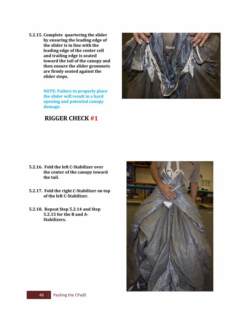
5.2.15. Complete quartering the slider
by ensuring the leading edge of the slider is in line with the leading edge of the center cell and trailing edge is seated toward the tail of the canopy and then ensure the slider grommets are firmly seated against the slider stops.
NOTE: Failure to properly place the slider will result in a hard opening and potential canopy damage.
RIGGER CHECK #1
5.2.16. Fold the left C-Stabilizer over the center of the canopy toward the tail.
5.2.17. Fold the right C-Stabilizer on top of the left C-Stabilizer.
5.2.18. Repeat Step 5.2.14 and Step 5.2.15 for the B and A-Stabilizers.
Nose
Tail
47 Packing the CPadS
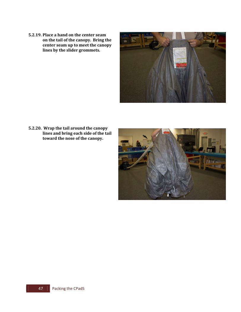
5.2.19. Place a hand on the center seam
on the tail of the canopy. Bring the center seam up to meet the canopy lines by the slider grommets.
5.2.20. Wrap the tail around the canopy lines and bring each side of the tail toward the nose of the canopy.
48 Packing the CPadS
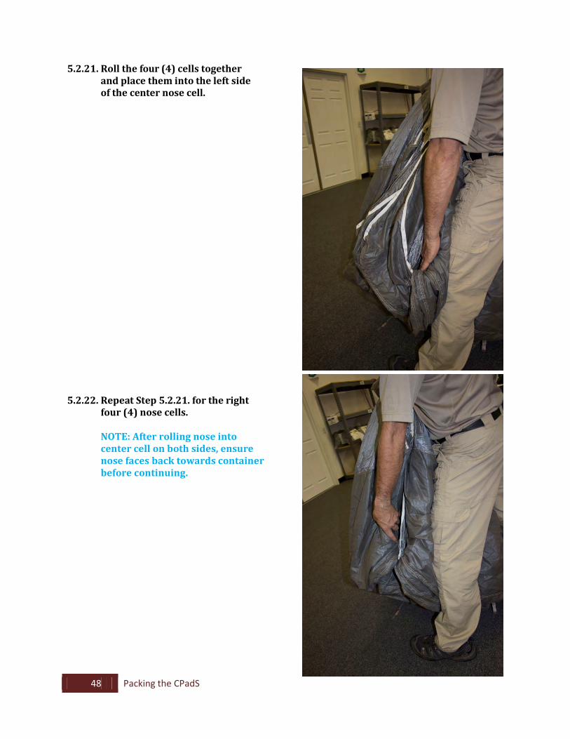
5.2.21. Roll the four (4) cells together and place them into the left side of the center nose cell.
5.2.22. Repeat Step 5.2.21. for the right
four (4) nose cells. NOTE: After rolling nose into
center cell on both sides, ensure nose faces back towards container before continuing.
49 Packing the CPadS
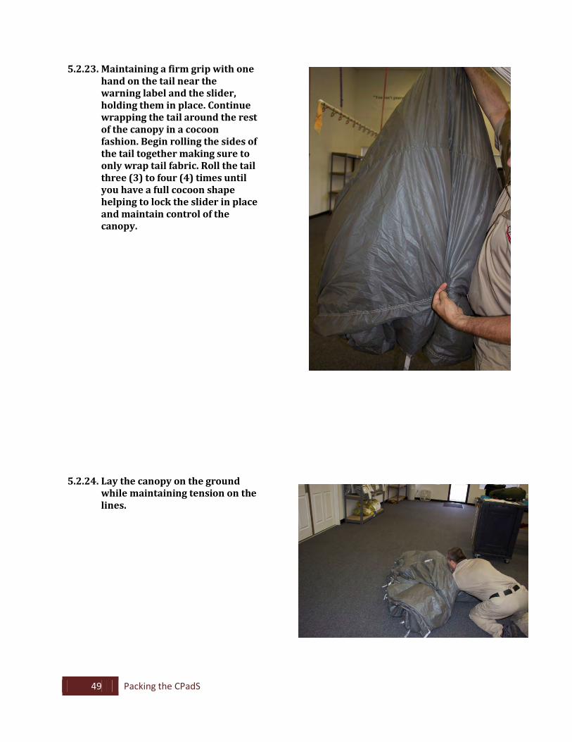
5.2.23. Maintaining a firm grip with one hand on the tail near the warning label and the slider, holding them in place. Continue wrapping the tail around the rest of the canopy in a cocoon fashion. Begin rolling the sides of the tail together making sure to only wrap tail fabric. Roll the tail three (3) to four (4) times until you have a full cocoon shape helping to lock the slider in place and maintain control of the canopy.
5.2.24. Lay the canopy on the ground while maintaining tension on the lines.
50 Packing the CPadS
5.3. Packing the Canopy into the Deployment Bag
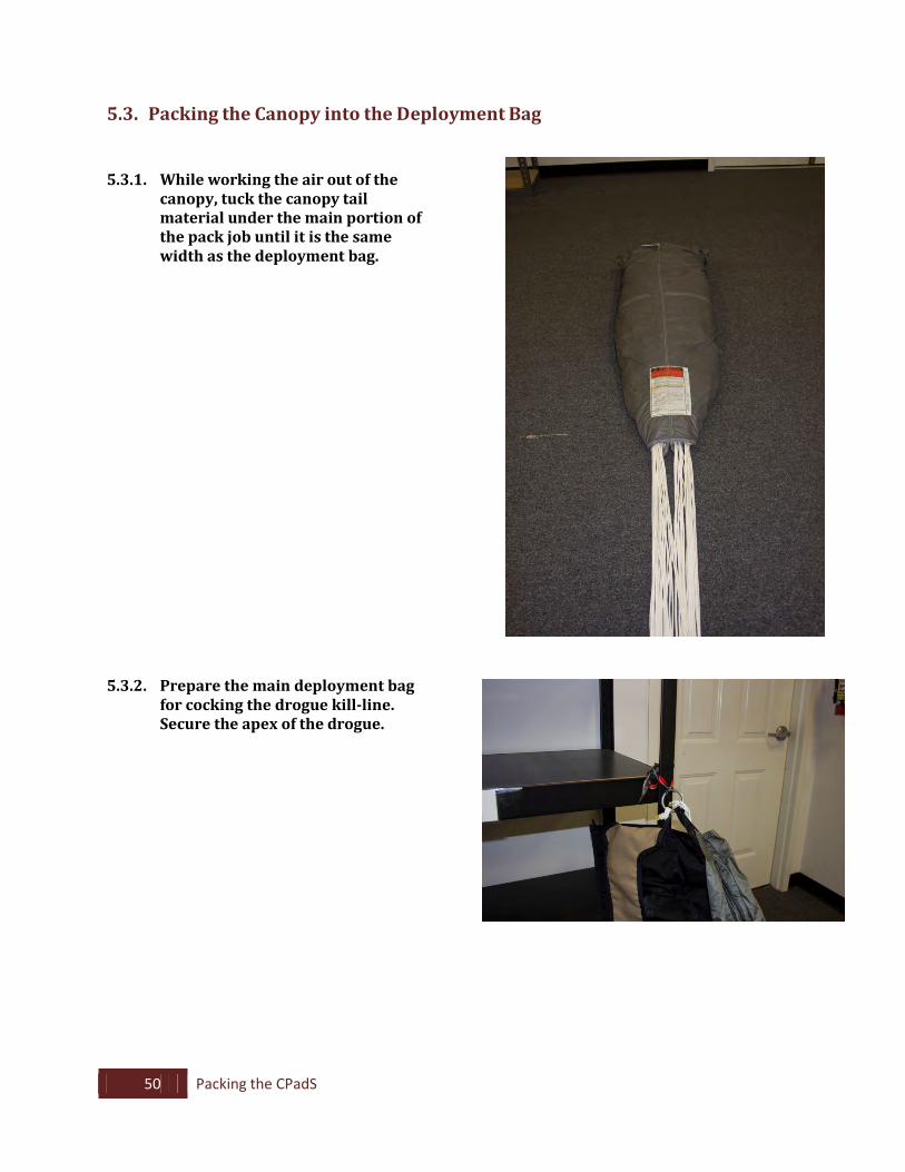
5.3.1. While working the air out of the
canopy, tuck the canopy tail material under the main portion of the pack job until it is the same width as the deployment bag.
5.3.2. Prepare the main deployment bag for cocking the drogue kill-line. Secure the apex of the drogue.
51 Packing the CPadS
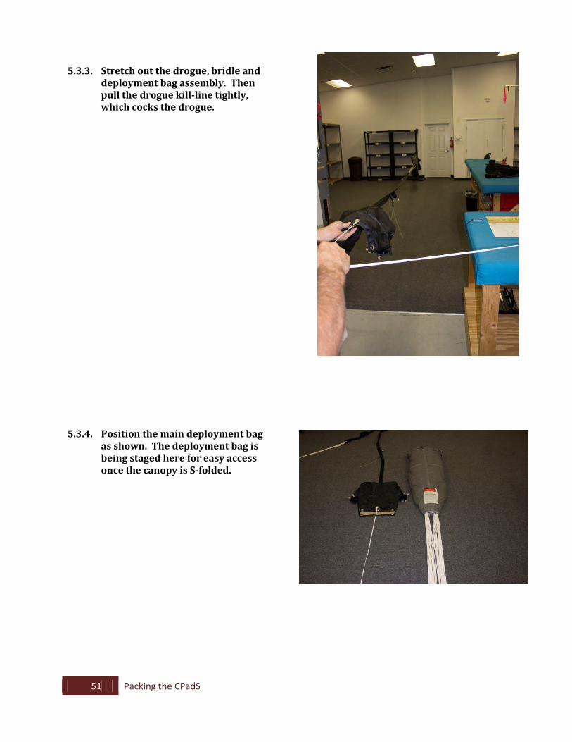
5.3.3. Stretch out the drogue, bridle and deployment bag assembly. Then pull the drogue kill-line tightly, which cocks the drogue.
5.3.4. Position the main deployment bag as shown. The deployment bag is being staged here for easy access once the canopy is S-folded.
52 Packing the CPadS
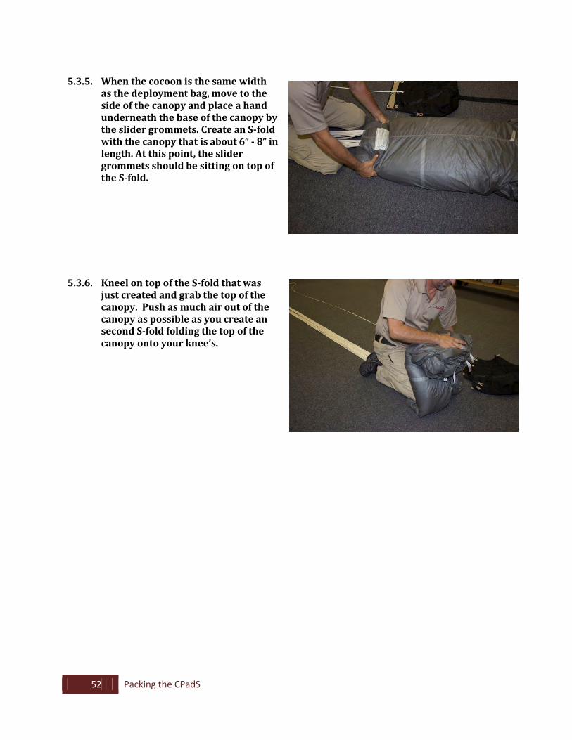
5.3.5. When the cocoon is the same width
as the deployment bag, move to the side of the canopy and place a hand underneath the base of the canopy by the slider grommets. Create an S-fold with the canopy that is about 6” - 8” in length. At this point, the slider grommets should be sitting on top of the S-fold.
5.3.6. Kneel on top of the S-fold that was just created and grab the top of the canopy. Push as much air out of the canopy as possible as you create an second S-fold folding the top of the canopy onto your knee’s.
53 Packing the CPadS
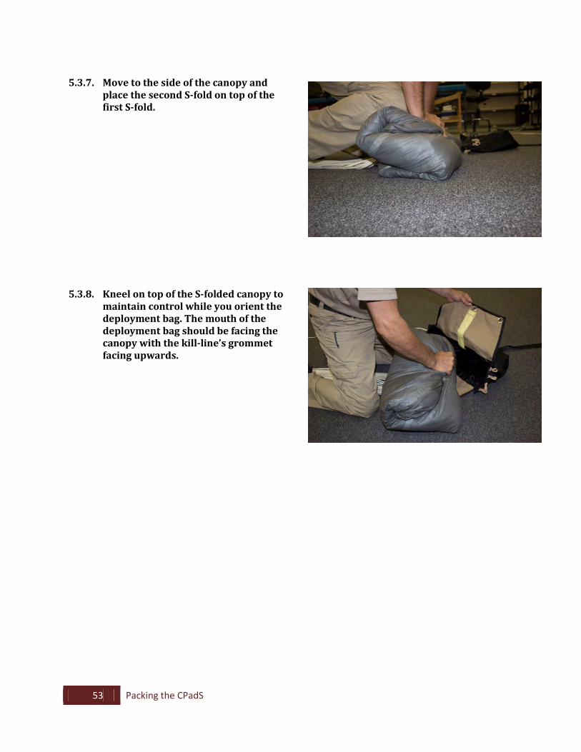
5.3.7. Move to the side of the canopy and
place the second S-fold on top of the first S-fold.
5.3.8. Kneel on top of the S-folded canopy to maintain control while you orient the deployment bag. The mouth of the deployment bag should be facing the canopy with the kill-line’s grommet facing upwards.
54 Packing the CPadS
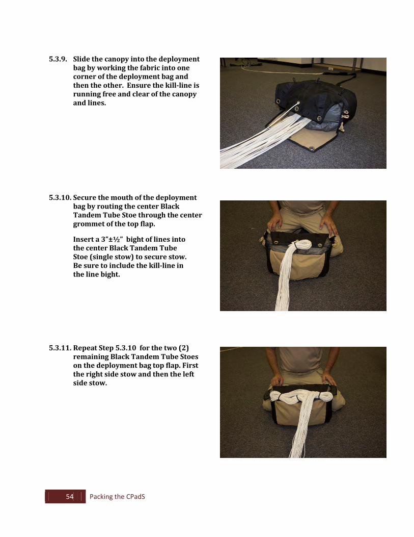
5.3.9. Slide the canopy into the deployment
bag by working the fabric into one corner of the deployment bag and then the other. Ensure the kill-line is running free and clear of the canopy and lines.
5.3.10. Secure the mouth of the deployment bag by routing the center Black Tandem Tube Stoe through the center grommet of the top flap.
Insert a 3”±½” bight of lines into the center Black Tandem Tube Stoe (single stow) to secure stow. Be sure to include the kill-line in the line bight.
5.3.11. Repeat Step 5.3.10 for the two (2) remaining Black Tandem Tube Stoes on the deployment bag top flap. First the right side stow and then the left side stow.
55 Packing the CPadS
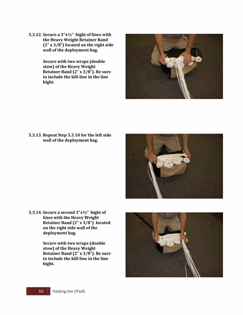
5.3.12. Secure a 3”±½” bight of lines with
the Heavy Weight Retainer Band (2” x 3/8”) located on the right side wall of the deployment bag.
Secure with two wraps (double
stow) of the Heavy Weight Retainer Band (2” x 3/8”). Be sure to include the kill-line in the line bight.
5.3.13. Repeat Step 5.3.10 for the left side wall of the deployment bag.
5.3.14. Secure a second 3”±½” bight of lines with the Heavy Weight Retainer Band (2” x 3/8”) located on the right side wall of the deployment bag.
Secure with two wraps (double
stow) of the Heavy Weight Retainer Band (2” x 3/8”). Be sure to include the kill-line in the line bight.
56 Packing the CPadS
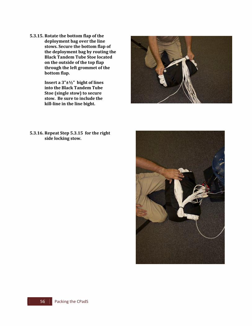
5.3.15. Rotate the bottom flap of the
deployment bag over the line stows. Secure the bottom flap of the deployment bag by routing the Black Tandem Tube Stoe located on the outside of the top flap through the left grommet of the bottom flap.
Insert a 3”±½” bight of lines into the Black Tandem Tube Stoe (single stow) to secure stow. Be sure to include the kill-line in the line bight.
5.3.16. Repeat Step 5.3.15 for the right side locking stow.
57 Packing the CPadS
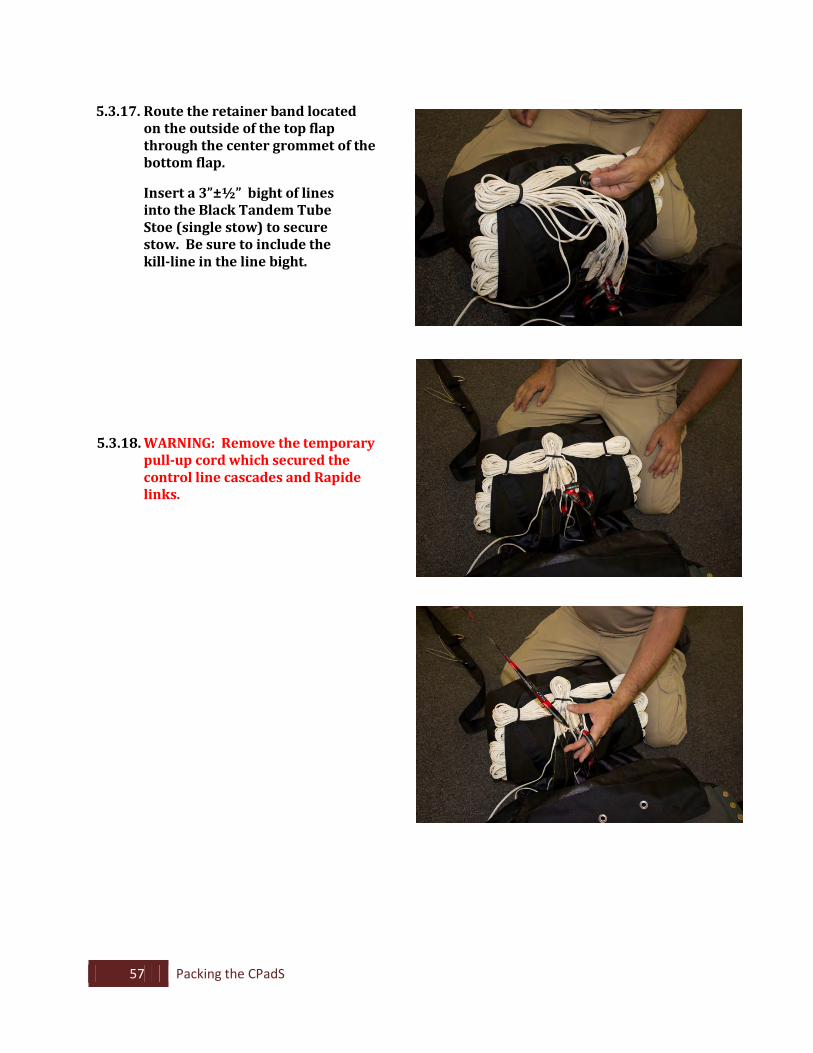
5.3.17. Route the retainer band located
on the outside of the top flap through the center grommet of the bottom flap.
Insert a 3”±½” bight of lines into the Black Tandem Tube Stoe (single stow) to secure stow. Be sure to include the kill-line in the line bight.
5.3.18. WARNING: Remove the temporary pull-up cord which secured the control line cascades and Rapide links.
58 Packing the CPadS
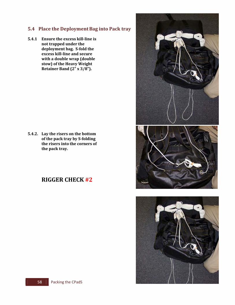
5.4 Place the Deployment Bag into Pack tray
5.4.1 Ensure the excess kill-line is not trapped under the deployment bag. S-fold the excess kill-line and secure with a double wrap (double stow) of the Heavy Weight Retainer Band (2” x 3/8”).
5.4.2. Lay the risers on the bottom of the pack tray by S-folding the risers into the corners of the pack tray.
RIGGER CHECK #2
59 Packing the CPadS
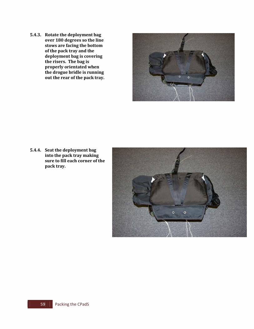
5.4.3. Rotate the deployment bag
over 180 degrees so the line stows are facing the bottom of the pack tray and the deployment bag is covering the risers. The bag is properly orientated when the drogue bridle is running out the rear of the pack tray.
5.4.4. Seat the deployment bag into the pack tray making sure to fill each corner of the pack tray.
60 Packing the CPadS
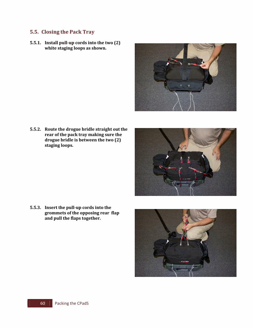
5.5. Closing the Pack Tray
5.5.1. Install pull-up cords into the two (2) white staging loops as shown.
5.5.2. Route the drogue bridle straight out the rear of the pack tray making sure the drogue bridle is between the two (2) staging loops.
5.5.3. Insert the pull-up cords into the
grommets of the opposing rear flap and pull the flaps together.
61 Packing the CPadS
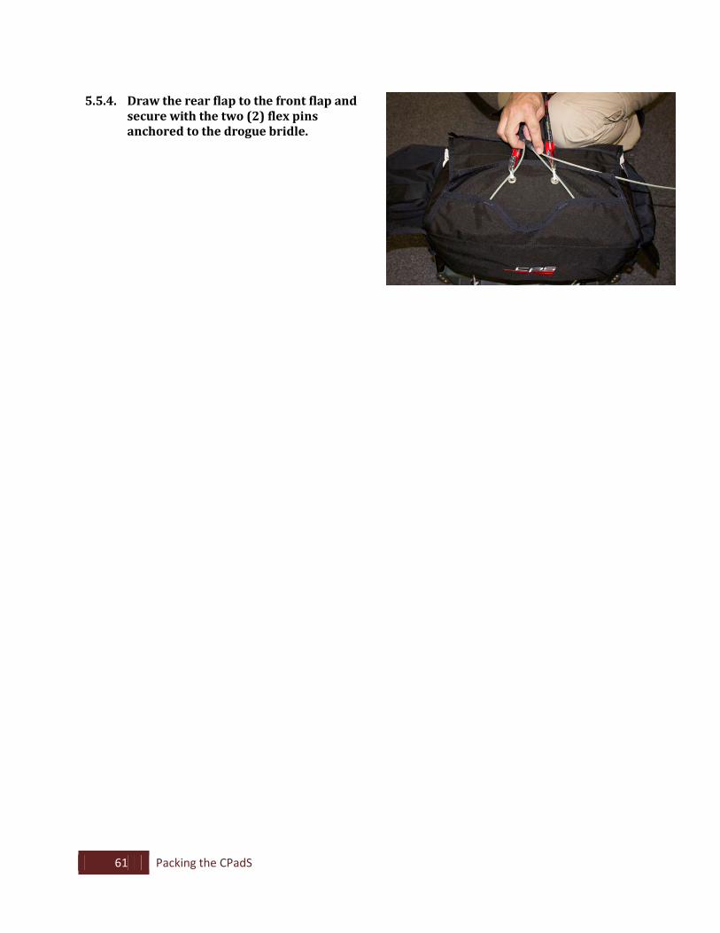
5.5.4. Draw the rear flap to the front flap and
secure with the two (2) flex pins anchored to the drogue bridle.
62 Packing the CPadS
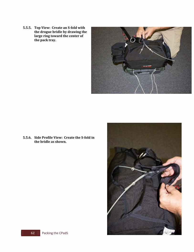
5.5.5. Top View: Create an S-fold with
the drogue bridle by drawing the large ring toward the center of the pack tray.
5.5.6. Side Profile View: Create the S-fold in the bridle as shown.
63 Packing the CPadS
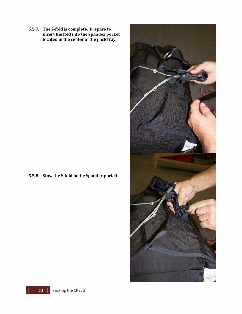
5.5.7. The S-fold is complete. Prepare to insert the fold into the Spandex pocket located in the center of the pack tray.
5.5.8. Stow the S-fold in the Spandex pocket.
64 Packing the CPadS
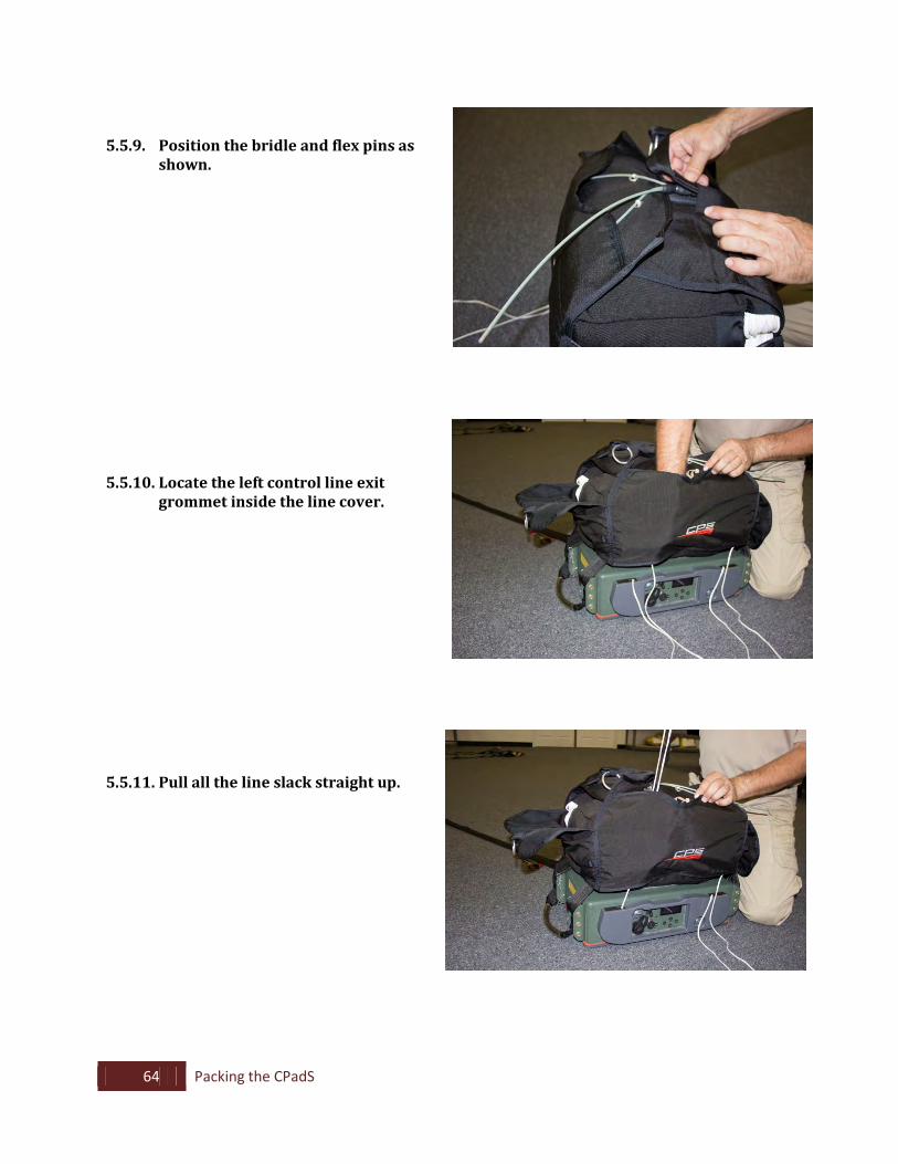
5.5.9. Position the bridle and flex pins as shown.
5.5.10. Locate the left control line exit grommet inside the line cover.
5.5.11. Pull all the line slack straight up.
65 Packing the CPadS
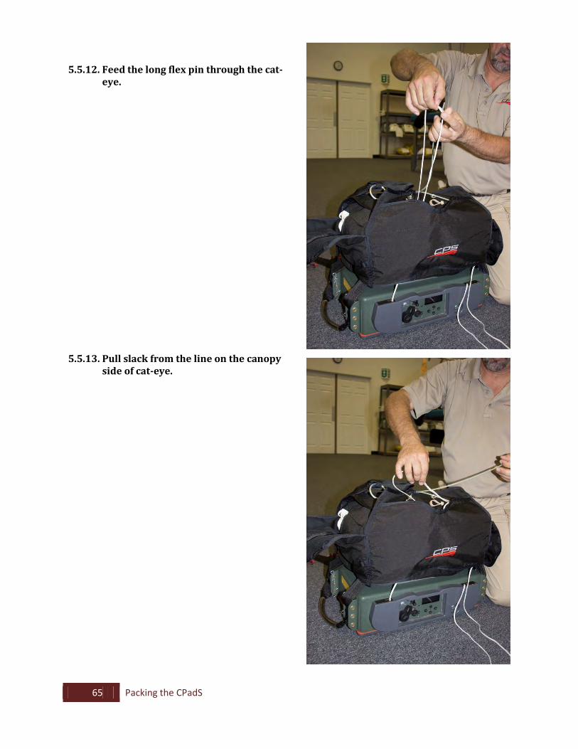
5.5.12. Feed the long flex pin through the cat-eye.
5.5.13. Pull slack from the line on the canopy side of cat-eye.
66 Packing the CPadS
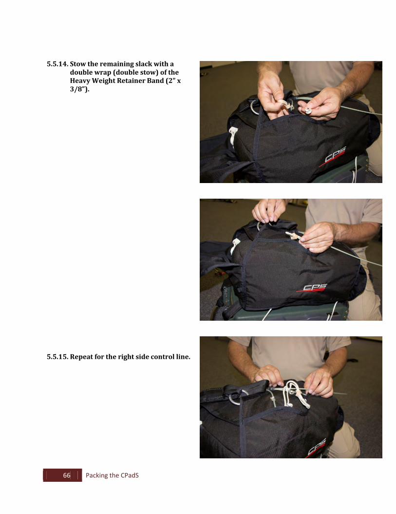
5.5.14. Stow the remaining slack with a double wrap (double stow) of the Heavy Weight Retainer Band (2” x 3/8”).
5.5.15. Repeat for the right side control line.
67 Packing the CPadS
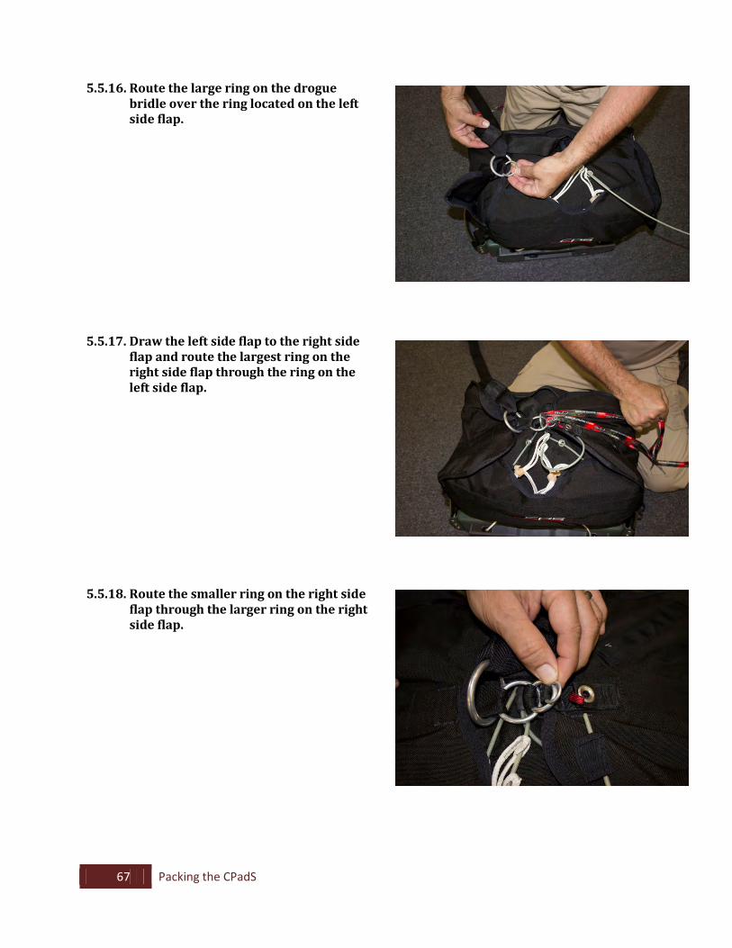
5.5.16. Route the large ring on the drogue bridle over the ring located on the left side flap.
5.5.17. Draw the left side flap to the right side
flap and route the largest ring on the right side flap through the ring on the left side flap.
5.5.18. Route the smaller ring on the right side flap through the larger ring on the right side flap.
68 Packing the CPadS
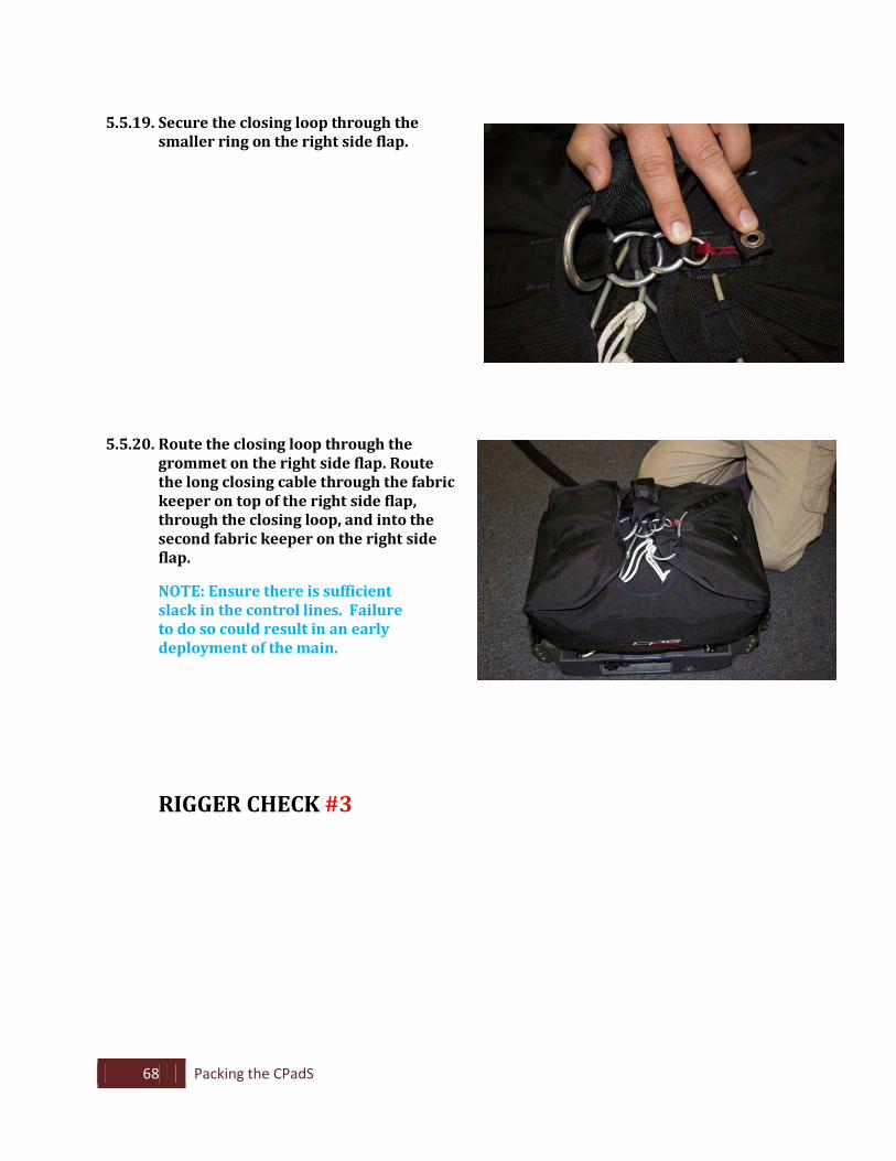
5.5.19. Secure the closing loop through the
smaller ring on the right side flap.
5.5.20. Route the closing loop through the grommet on the right side flap. Route the long closing cable through the fabric keeper on top of the right side flap, through the closing loop, and into the second fabric keeper on the right side flap.
NOTE: Ensure there is sufficient slack in the control lines. Failure to do so could result in an early deployment of the main.
RIGGER CHECK #3
69 Packing the CPadS
5.6. Stowing the Recovery Bag
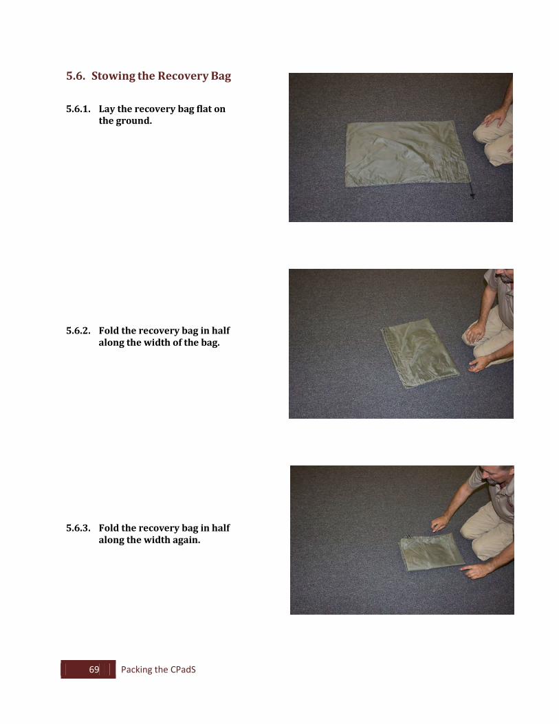
5.6.1. Lay the recovery bag flat on the ground.
5.6.2. Fold the recovery bag in half
along the width of the bag.
5.6.3. Fold the recovery bag in half along the width again.
70 Packing the CPadS
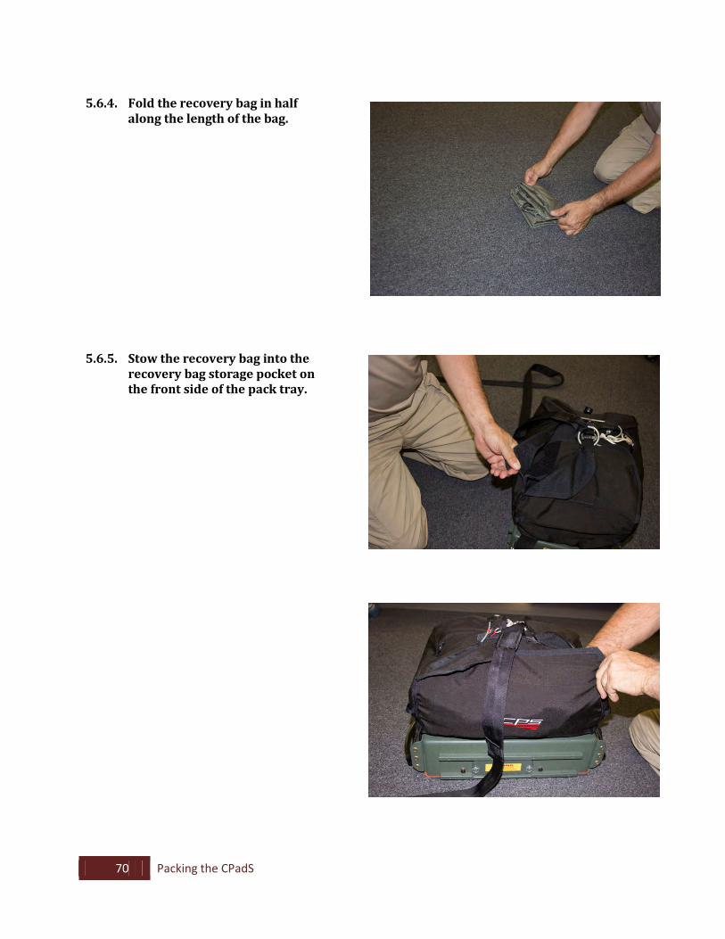
5.6.4. Fold the recovery bag in half
along the length of the bag.
5.6.5. Stow the recovery bag into the recovery bag storage pocket on the front side of the pack tray.
71 Packing the CPadS
RIGGER CHECK #4
72 Packing the CPadS
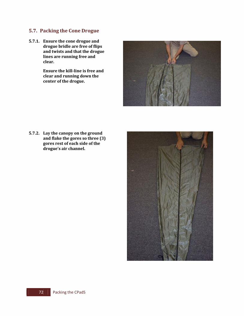
5.7. Packing the Cone Drogue
5.7.1. Ensure the cone drogue and drogue bridle are free of flips and twists and that the drogue lines are running free and clear.
Ensure the kill-line is free and
clear and running down the center of the drogue.
5.7.2. Lay the canopy on the ground
and flake the gores so three (3) gores rest of each side of the drogue’s air channel.
73 Packing the CPadS
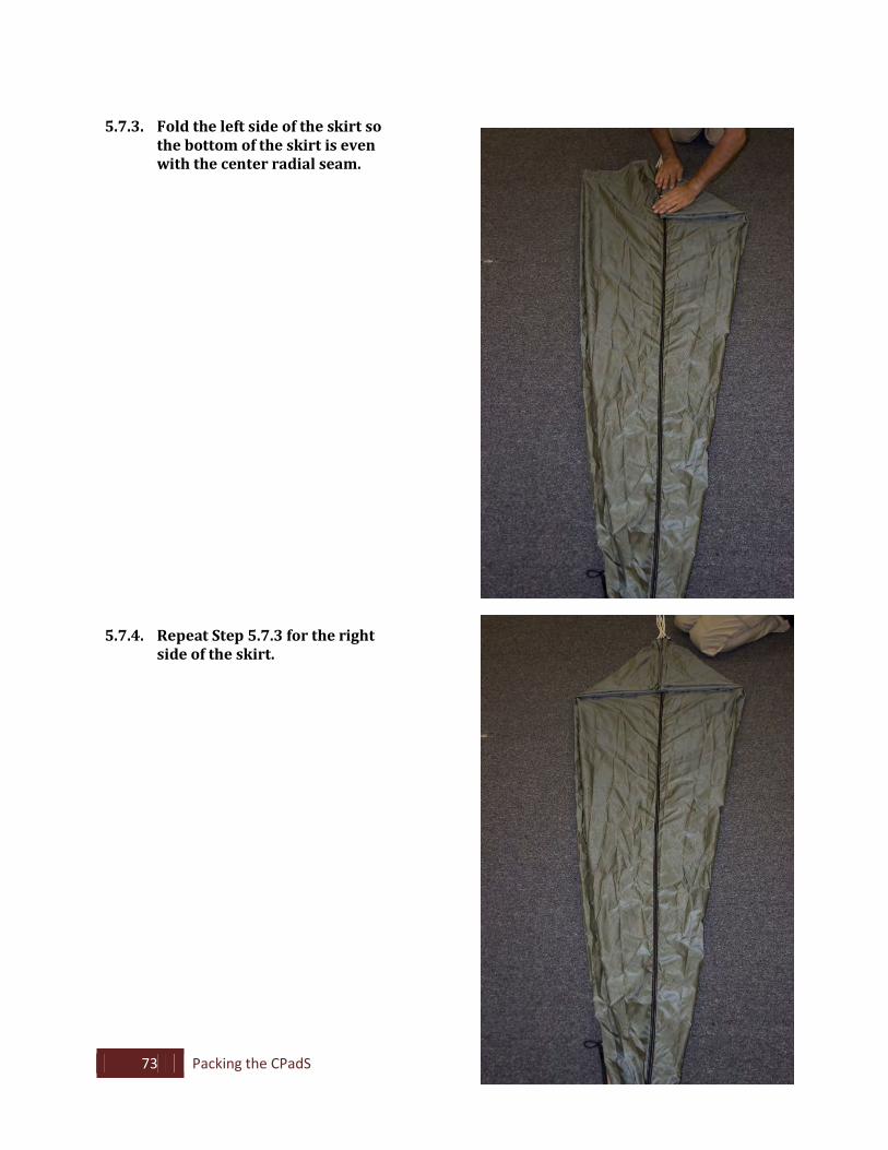
5.7.3. Fold the left side of the skirt so
the bottom of the skirt is even with the center radial seam.
5.7.4. Repeat Step 5.7.3 for the right side of the skirt.
74 Packing the CPadS
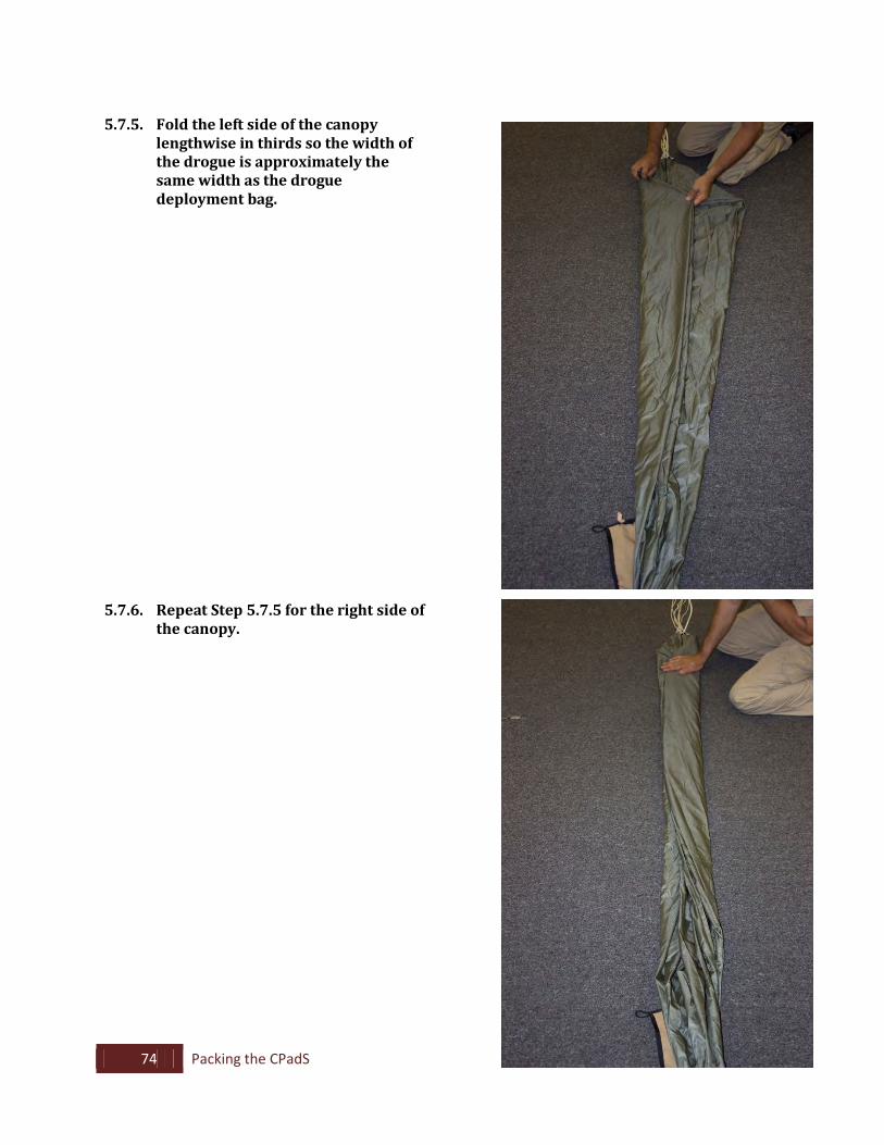
5.7.5. Fold the left side of the canopy
lengthwise in thirds so the width of the drogue is approximately the same width as the drogue deployment bag.
5.7.6. Repeat Step 5.7.5 for the right side of the canopy.
75 Packing the CPadS
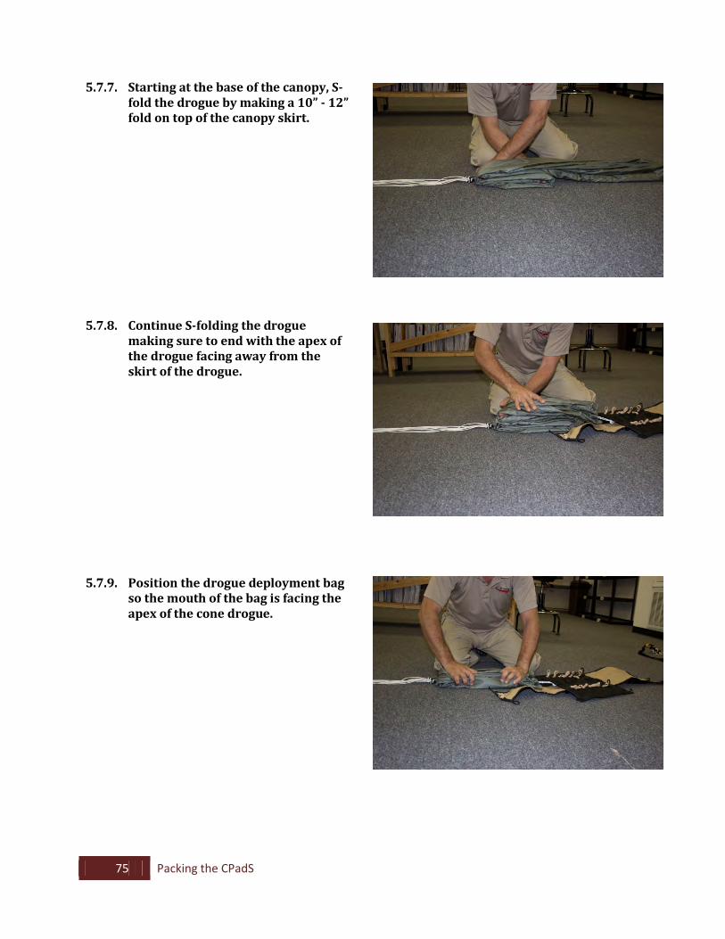
5.7.7. Starting at the base of the canopy, S-fold the drogue by making a 10” - 12” fold on top of the canopy skirt.
5.7.8. Continue S-folding the drogue making sure to end with the apex of the drogue facing away from the skirt of the drogue.
5.7.9. Position the drogue deployment bag so the mouth of the bag is facing the apex of the cone drogue.
76 Packing the CPadS
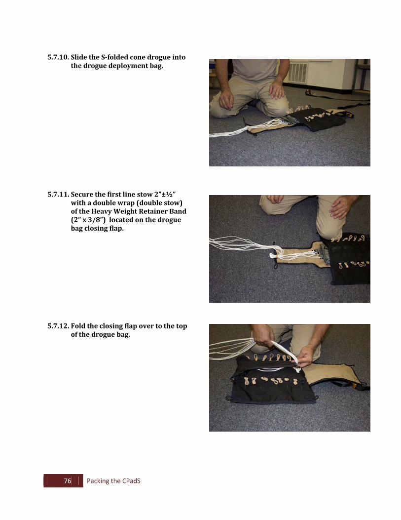
5.7.10. Slide the S-folded cone drogue into
the drogue deployment bag.
5.7.11. Secure the first line stow 2”±½” with a double wrap (double stow) of the Heavy Weight Retainer Band (2” x 3/8”) located on the drogue bag closing flap.
5.7.12. Fold the closing flap over to the top of the drogue bag.
77 Packing the CPadS
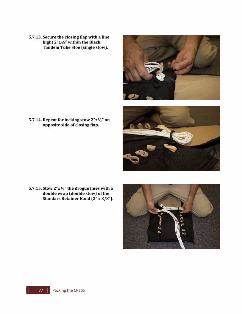
5.7.13. Secure the closing flap with a line bight 2”±½” within the Black Tandem Tube Stoe (single stow).
5.7.14. Repeat for locking stow 2”±½” on opposite side of closing flap.
5.7.15. Stow 2”±½” the drogue lines with a double wrap (double stow) of the Standars Retainer Band (2” x 3/8”).
78 Packing the CPadS
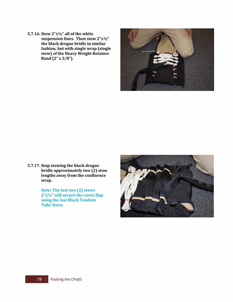
5.7.16. Stow 2”±½” all of the white
suspension lines. Then stow 2”±½” the black drogue bridle in similar fashion, but with single wrap (single stow) of the Heavy Weight Retainer Band (2” x 3/8”).
5.7.17. Stop stowing the black drogue bridle approximately two (2) stow lengths away from the confluence wrap.
Note: The last two (2) stows 2”±½” will secure the cover flap using the last Black Tandem Tube Stoes.
79 Packing the CPadS
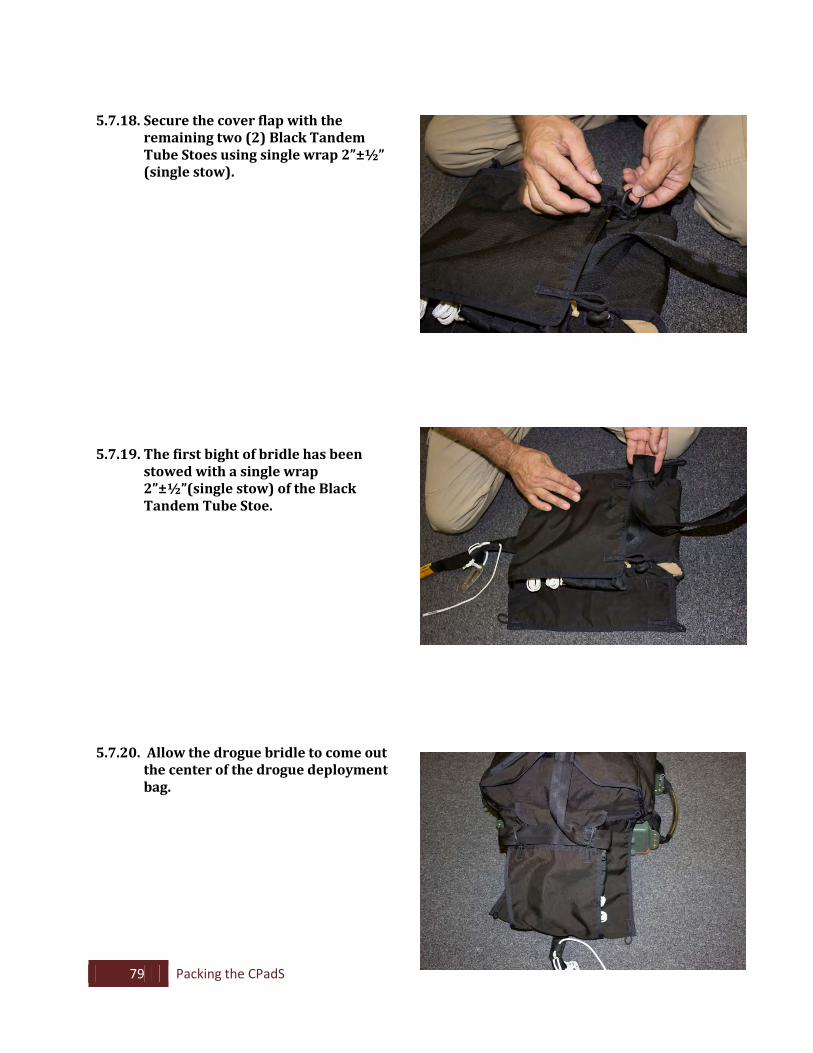
5.7.18. Secure the cover flap with the
remaining two (2) Black Tandem Tube Stoes using single wrap 2”±½” (single stow).
5.7.19. The first bight of bridle has been stowed with a single wrap 2”±½”(single stow) of the Black Tandem Tube Stoe.
5.7.20. Allow the drogue bridle to come out the center of the drogue deployment bag.
80 Packing the CPadS
5.8. Securing the Drogue to the Pack Tray
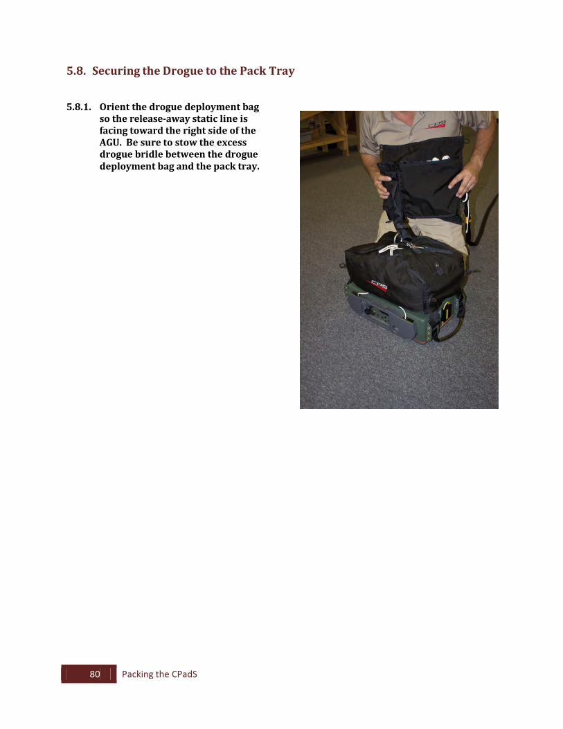
5.8.1. Orient the drogue deployment bag
so the release-away static line is facing toward the right side of the AGU. Be sure to stow the excess drogue bridle between the drogue deployment bag and the pack tray.
81 Packing the CPadS
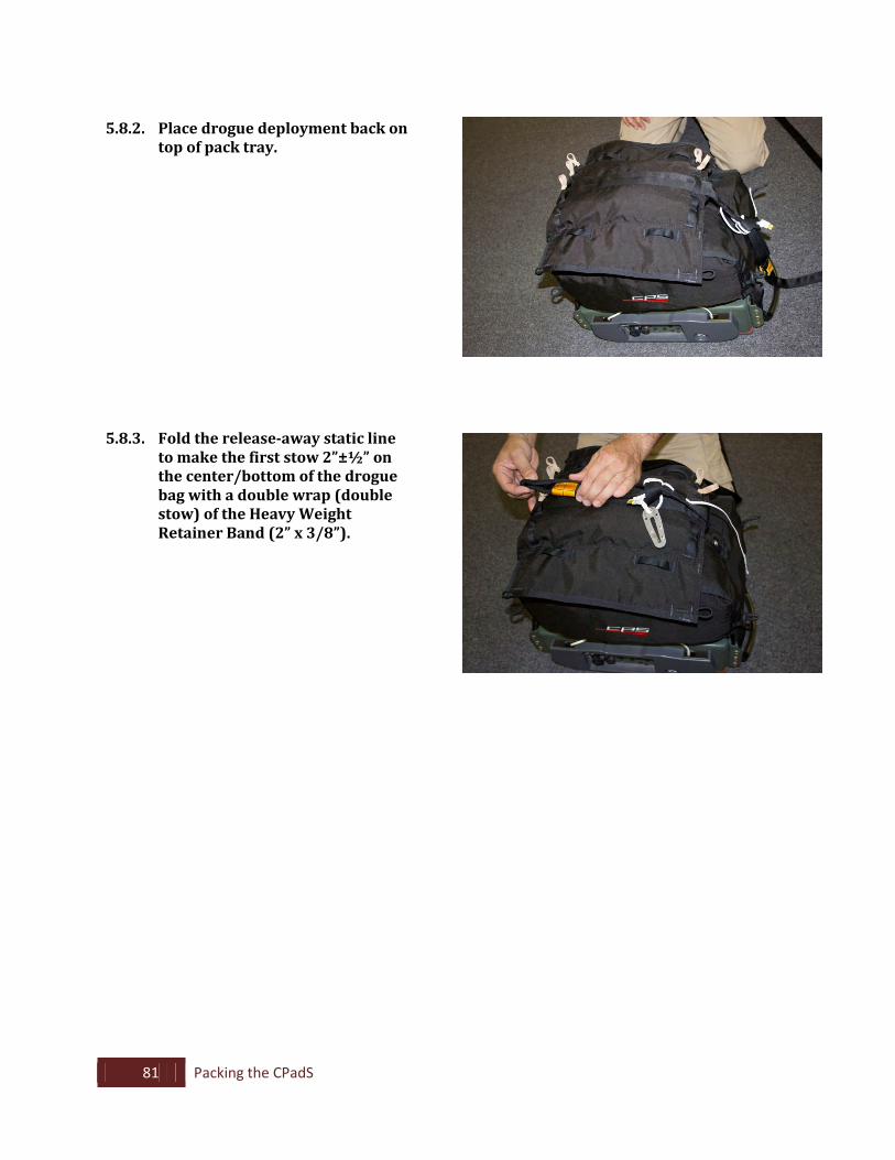
5.8.2. Place drogue deployment back on
top of pack tray.
5.8.3. Fold the release-away static line
to make the first stow 2”±½” on the center/bottom of the drogue bag with a double wrap (double stow) of the Heavy Weight Retainer Band (2” x 3/8”).
82 Packing the CPadS
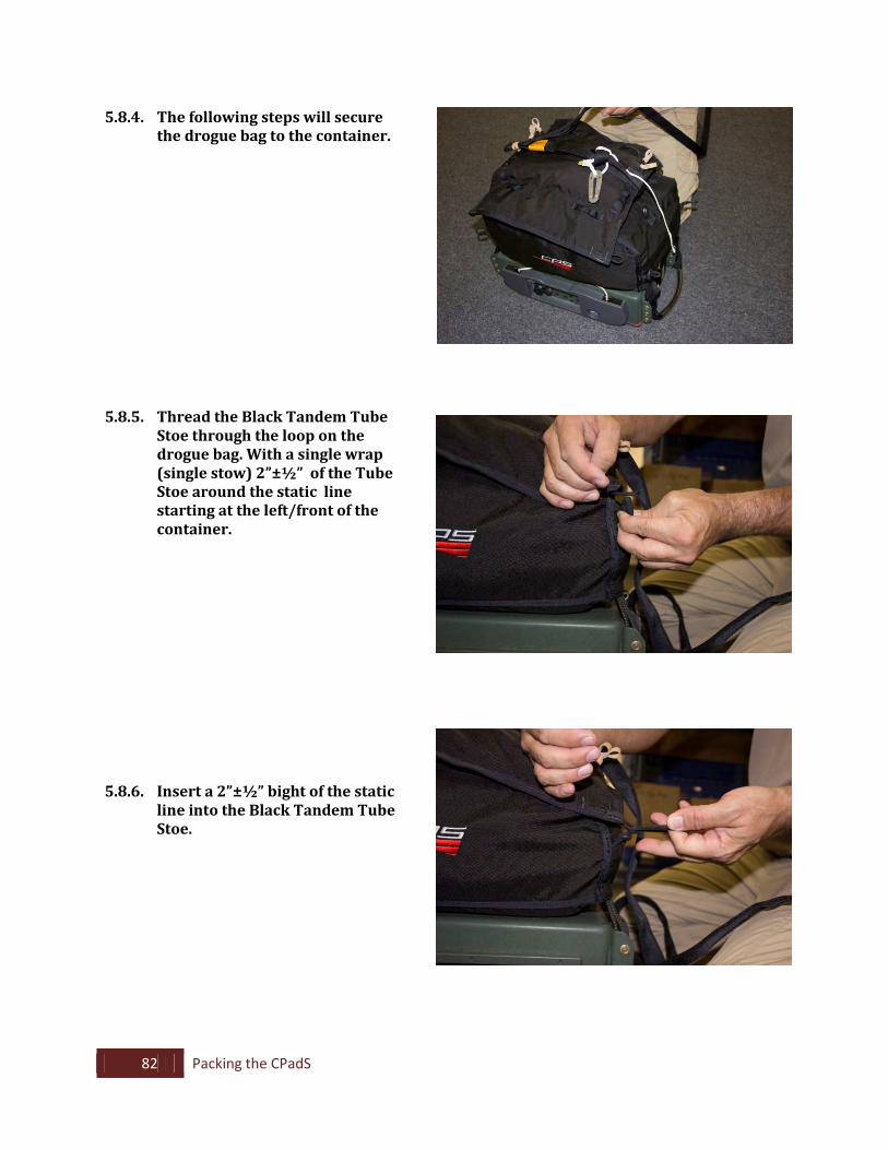
5.8.4. The following steps will secure the drogue bag to the container.
5.8.5. Thread the Black Tandem Tube
Stoe through the loop on the drogue bag. With a single wrap (single stow) 2”±½” of the Tube Stoe around the static line starting at the left/front of the container.
5.8.6. Insert a 2”±½” bight of the static
line into the Black Tandem Tube Stoe.
83 Packing the CPadS
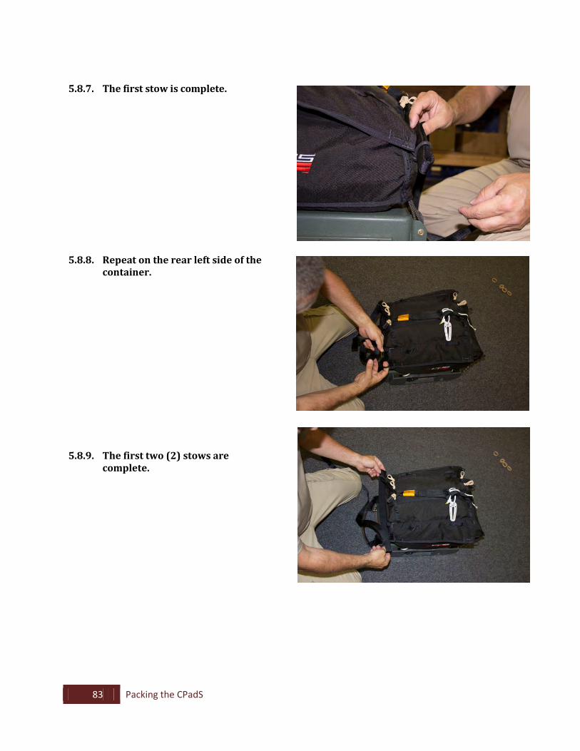
5.8.7. The first stow is complete. 5.8.8. Repeat on the rear left side of the
container. 5.8.9. The first two (2) stows are
complete.
84 Packing the CPadS
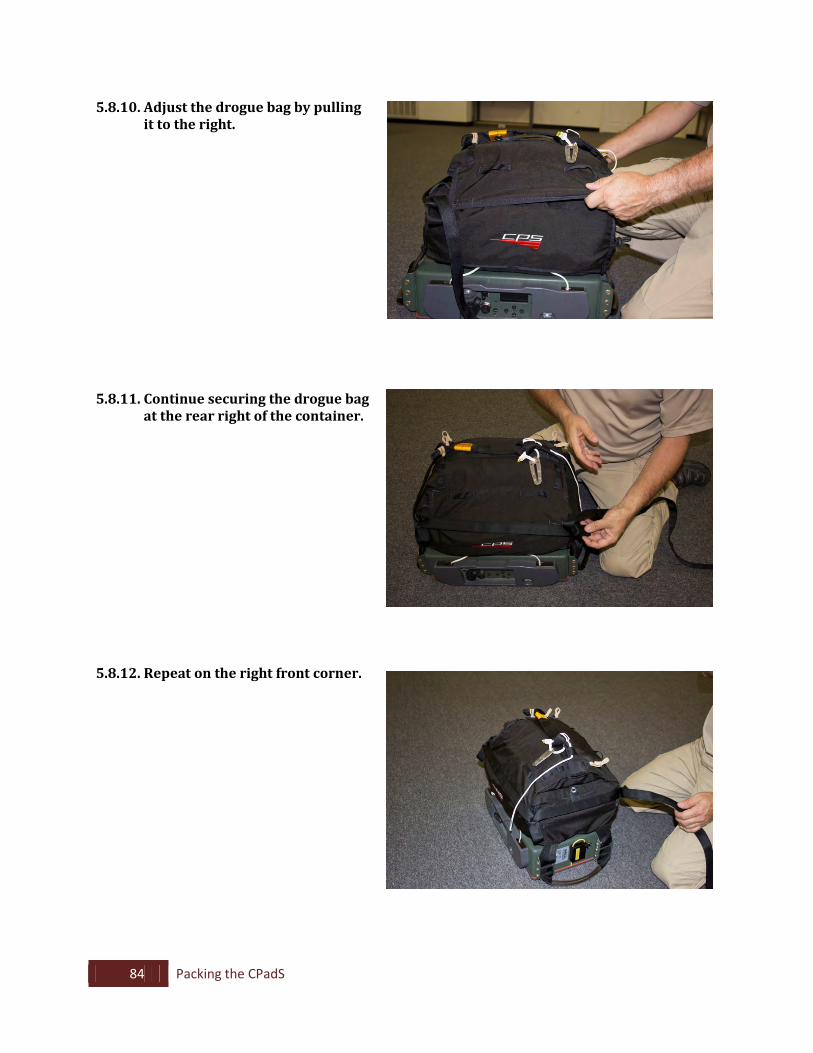
5.8.10. Adjust the drogue bag by pulling it to the right.
5.8.11. Continue securing the drogue bag
at the rear right of the container. 5.8.12. Repeat on the right front corner.
85 Packing the CPadS
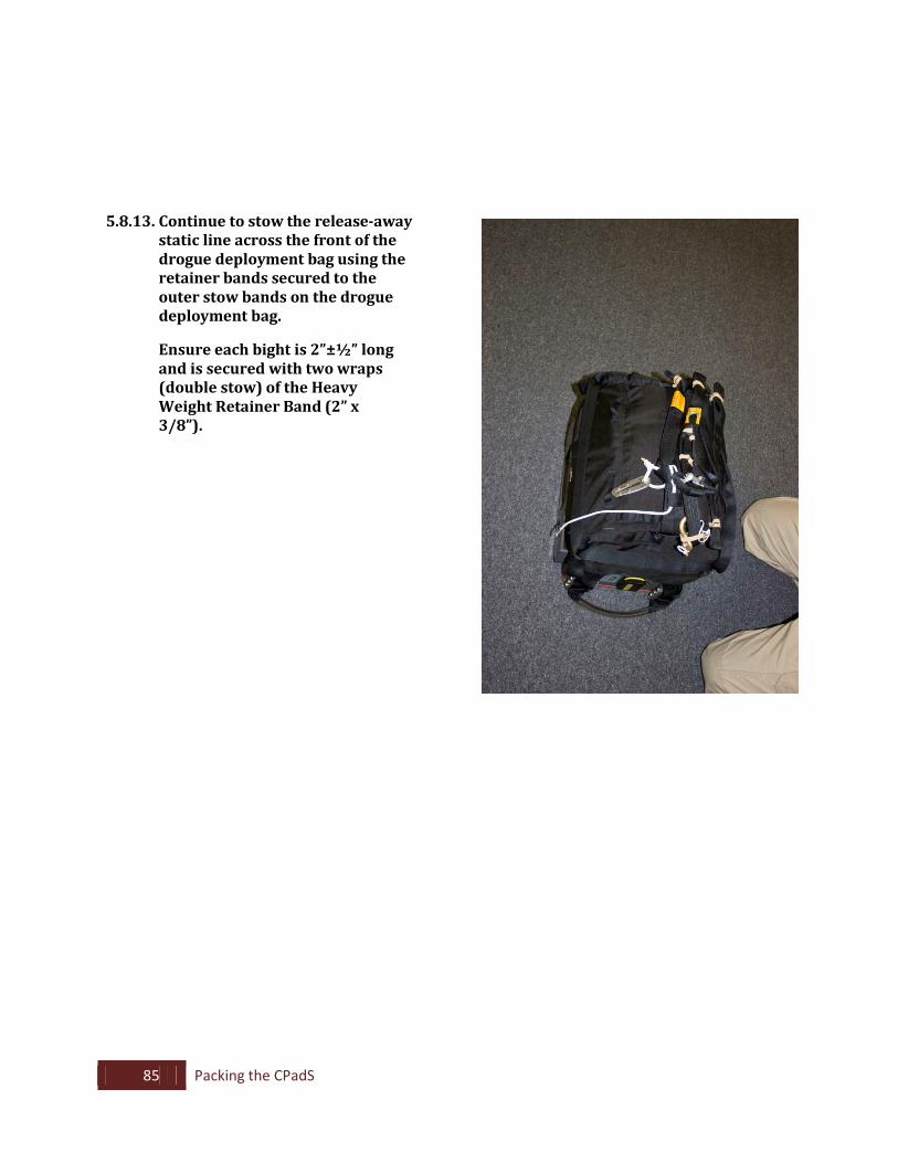
5.8.13. Continue to stow the release-away static line across the front of the drogue deployment bag using the retainer bands secured to the outer stow bands on the drogue deployment bag.
Ensure each bight is 2”±½” long and is secured with two wraps (double stow) of the Heavy Weight Retainer Band (2” x 3/8”).
86 Packing the CPadS
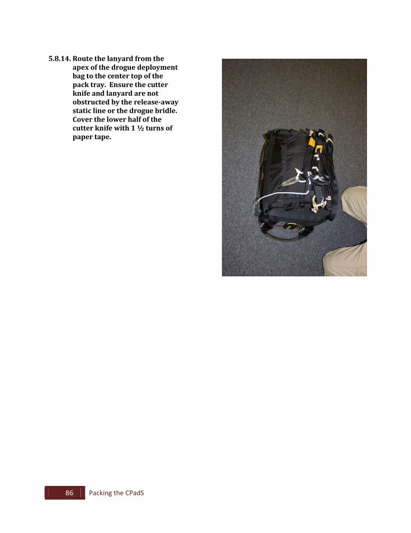
5.8.14. Route the lanyard from the
apex of the drogue deployment bag to the center top of the pack tray. Ensure the cutter knife and lanyard are not obstructed by the release-away static line or the drogue bridle. Cover the lower half of the cutter knife with 1 ½ turns of paper tape.
87 Packing the CPadS
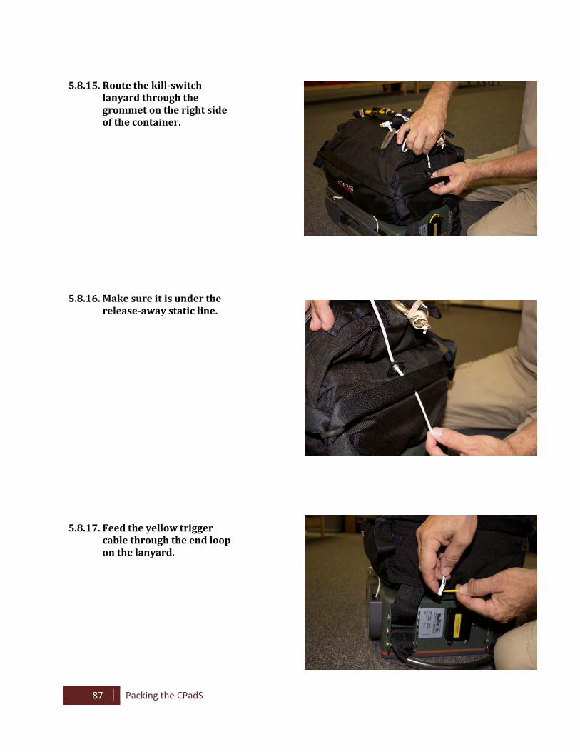
5.8.15. Route the kill-switch
lanyard through the grommet on the right side of the container.
5.8.16. Make sure it is under the
release-away static line. 5.8.17. Feed the yellow trigger
cable through the end loop on the lanyard.
88 Packing the CPadS
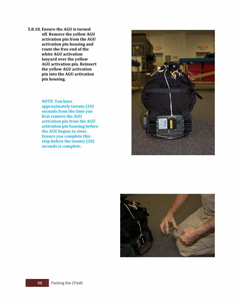
5.8.18. Ensure the AGU is turned off. Remove the yellow AGU activation pin from the AGU activation pin housing and route the free end of the white AGU activation lanyard over the yellow AGU activation pin. Reinsert the yellow AGU activation pin into the AGU activation pin housing.
NOTE: You have
approximately twenty (20) seconds from the time you first remove the AGU activation pin from the AGU activation pin housing before the AGU begins to steer. Ensure you complete this step before the twenty (20) seconds is complete.
89 Packing the CPadS
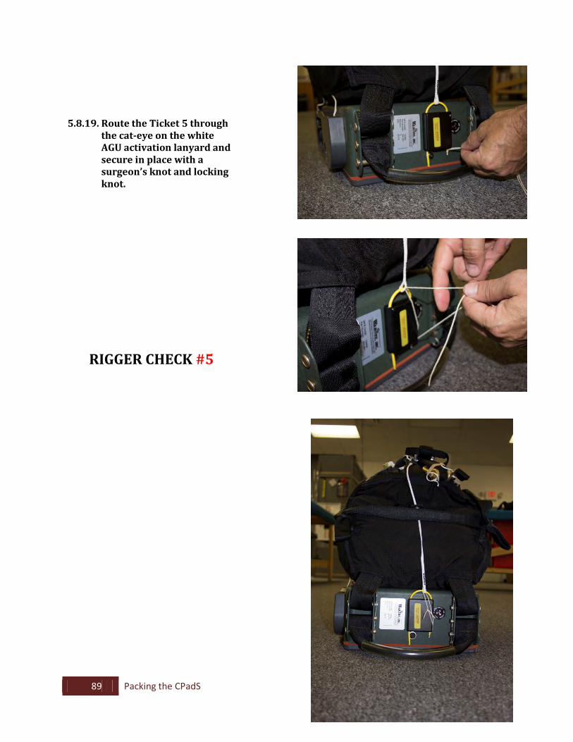
5.8.19. Route the Ticket 5 through
the cat-eye on the white AGU activation lanyard and secure in place with a surgeon’s knot and locking knot.
RIGGER CHECK #5
90 Rigging the CPadS to the Payload
6. Rigging the CPadS to the Payload
6.1. Attaching the 4-Point Suspension Swivel Harness
6.1.1. Position the 4-point suspension swivel harness on top of the payload. The payload should be pre-rigged with four (4) D-rings as connection points.
6.1.2. Connect the 4-point suspension swivel
harness to the four (4) D-rings in a clockwise fashion making sure to remove all twists prior to connecting. Secure the harness clips to the D- rings with two (2) turns of paper tape.
6.1.3. Lay the swivel portion of the harness
in the center front side of the payload.
6.1.4. Lay an AGU on top of the payload with the AGU control panel facing the aft center side of the payload.
6.1.5. Remove the clevis pins from the
lowest part of the brackets located on the sides of the AGU.
6.1.6. Insert the remaining suspension
harness points in a clockwise fashion into the brackets and secure in place with the clevis pins and retainer clips. Ensure the retainer clips are seated flat against the bracket and that all twists have been removed from the harness prior to installation.
91 Rigging the CPadS to the Payload
6.2. Securing the AGU to the Payload
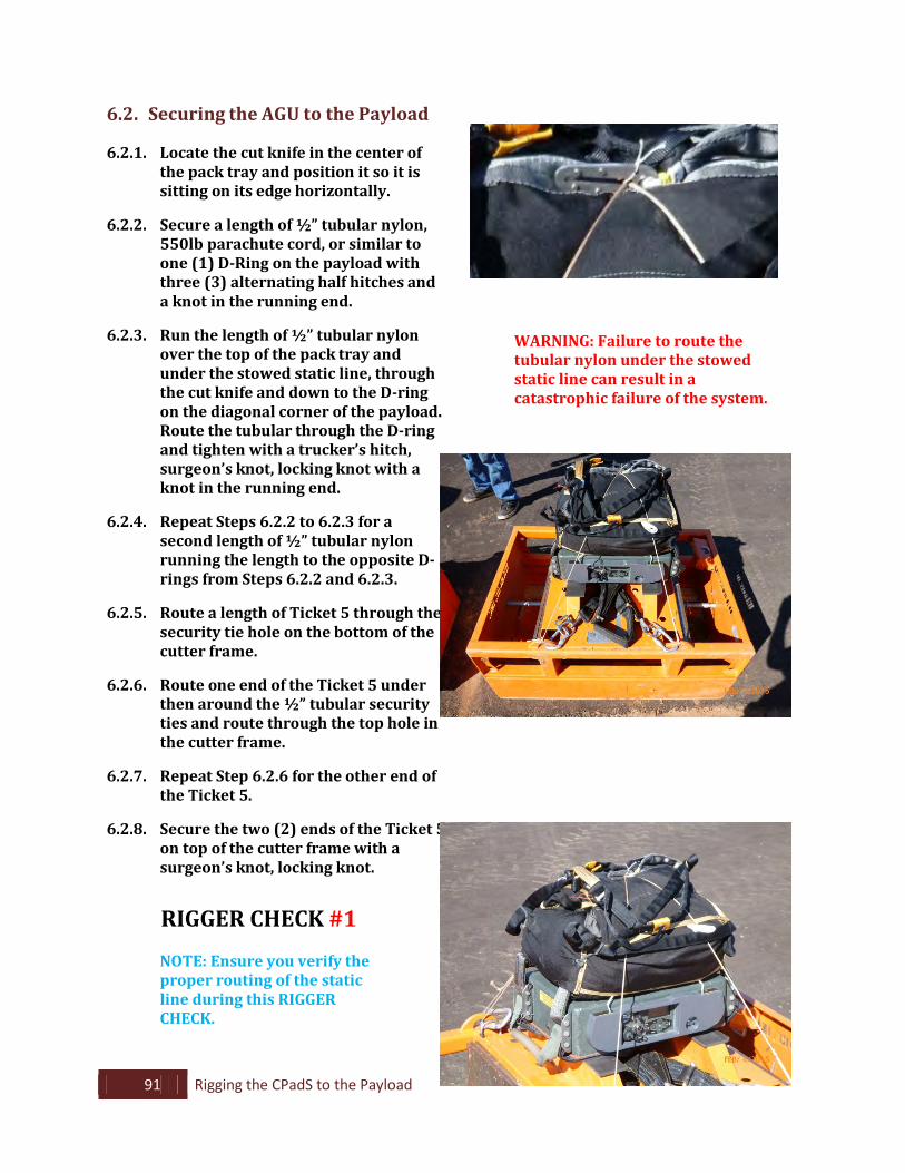
6.2.1. Locate the cut knife in the center of the pack tray and position it so it is sitting on its edge horizontally.
6.2.2. Secure a length of ½” tubular nylon,
550lb parachute cord, or similar to one (1) D-Ring on the payload with three (3) alternating half hitches and a knot in the running end.
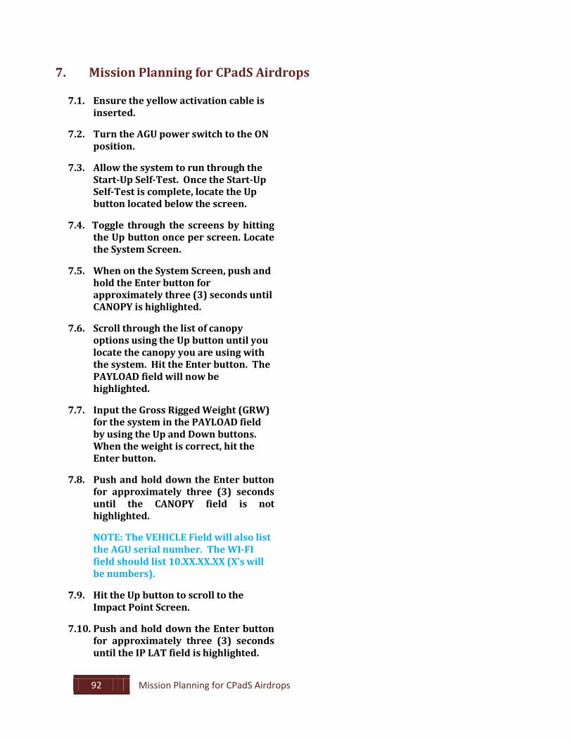
6.2.3. Run the length of ½” tubular nylon
over the top of the pack tray and under the stowed static line, through the cut knife and down to the D-ring on the diagonal corner of the payload. Route the tubular through the D-ring and tighten with a trucker’s hitch, surgeon’s knot, locking knot with a knot in the running end.
6.2.4. Repeat Steps 6.2.2 to 6.2.3 for a
second length of ½” tubular nylon running the length to the opposite D- rings from Steps 6.2.2 and 6.2.3.
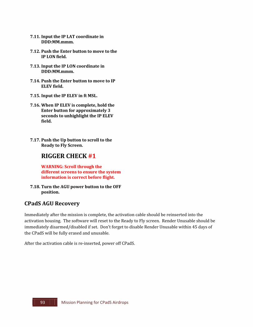
6.2.5. Route a length of Ticket 5 through the
security tie hole on the bottom of the cutter frame.
6.2.6. Route one end of the Ticket 5 under
then around the ½” tubular security ties and route through the top hole in the cutter frame.
6.2.7. Repeat Step 6.2.6 for the other end of
the Ticket 5.
6.2.8. Secure the two (2) ends of the Ticket 5 on top of the cutter frame with a surgeon’s knot, locking knot.
RIGGER CHECK #1
NOTE: Ensure you verify the proper routing of the static line during this RIGGER CHECK.
WARNING: Failure to route the tubular nylon under the stowed static line can result in a catastrophic failure of the system.
92 Mission Planning for CPadS Airdrops
7. Mission Planning for CPadS Airdrops
7.1. Ensure the yellow activation cable is
inserted. 7.2. Turn the AGU power switch to the ON
position. 7.3. Allow the system to run through the
Start-Up Self-Test. Once the Start-Up Self-Test is complete, locate the Up button located below the screen.
7.4. Toggle through the screens by hitting
the Up button once per screen. Locate the System Screen.
7.5. When on the System Screen, push and
hold the Enter button for approximately three (3) seconds until CANOPY is highlighted.
7.6. Scroll through the list of canopy
options using the Up button until you locate the canopy you are using with the system. Hit the Enter button. The PAYLOAD field will now be highlighted.
7.7. Input the Gross Rigged Weight (GRW)
for the system in the PAYLOAD field by using the Up and Down buttons. When the weight is correct, hit the Enter button.
7.8. Push and hold down the Enter button
for approximately three (3) seconds until the CANOPY field is not highlighted.
NOTE: The VEHICLE Field will also list
the AGU serial number. The WI-FI field should list 10.XX.XX.XX (X’s will be numbers).
7.9. Hit the Up button to scroll to the
Impact Point Screen. 7.10. Push and hold down the Enter button
for approximately three (3) seconds until the IP LAT field is highlighted.
93 Mission Planning for CPadS Airdrops
7.11. Input the IP LAT coordinate in
DDD:MM.mmm. 7.12. Push the Enter button to move to the
IP LON field. 7.13. Input the IP LON coordinate in
DDD:MM.mmm. 7.14. Push the Enter button to move to IP
ELEV field. 7.15. Input the IP ELEV in ft MSL. 7.16. When IP ELEV is complete, hold the
Enter button for approximately 3 seconds to unhighlight the IP ELEV field.
7.17. Push the Up button to scroll to the
Ready to Fly Screen.
RIGGER CHECK #1 WARNING: Scroll through the
different screens to ensure the system information is correct before flight.
7.18. Turn the AGU power button to the OFF
position.
CPadS AGU Recovery
Immediately after the mission is complete, the activation cable should be reinserted into the activation housing. The software will reset to the Ready to Fly screen. Render Unusable should be immediately disarmed/disabled if set. Don’t forget to disable Render Unusable within 45 days of the CPadS will be fully erased and unusable.
After the activation cable is re-inserted, power off CPadS.
94 System Maintenance
8. System Maintenance
8.1. Shelf Life The CPadS can sit on the shelf for up to 360 days without needing to be repacked. After the 360 day mark, unpack the system and begin the repack process from Section 5. Ensure the system is stored in a climate controlled location and that the system is not exposed to water during storage. 8.2. Inspection Cycle The CPadS should be inspected after each drop for damage and wear. Any damage should be repaired prior to dropping again. When factory maintenance and/or repairs are required, contact CPS Customer Service or your CPS Account Executive. Request an RMA number prior to returning the equipment. 8.3. Software Updates Users should contact CPS every 180-days for software updates. Contact information is located in Section 1.3 of this manual.
95 System Maintenance
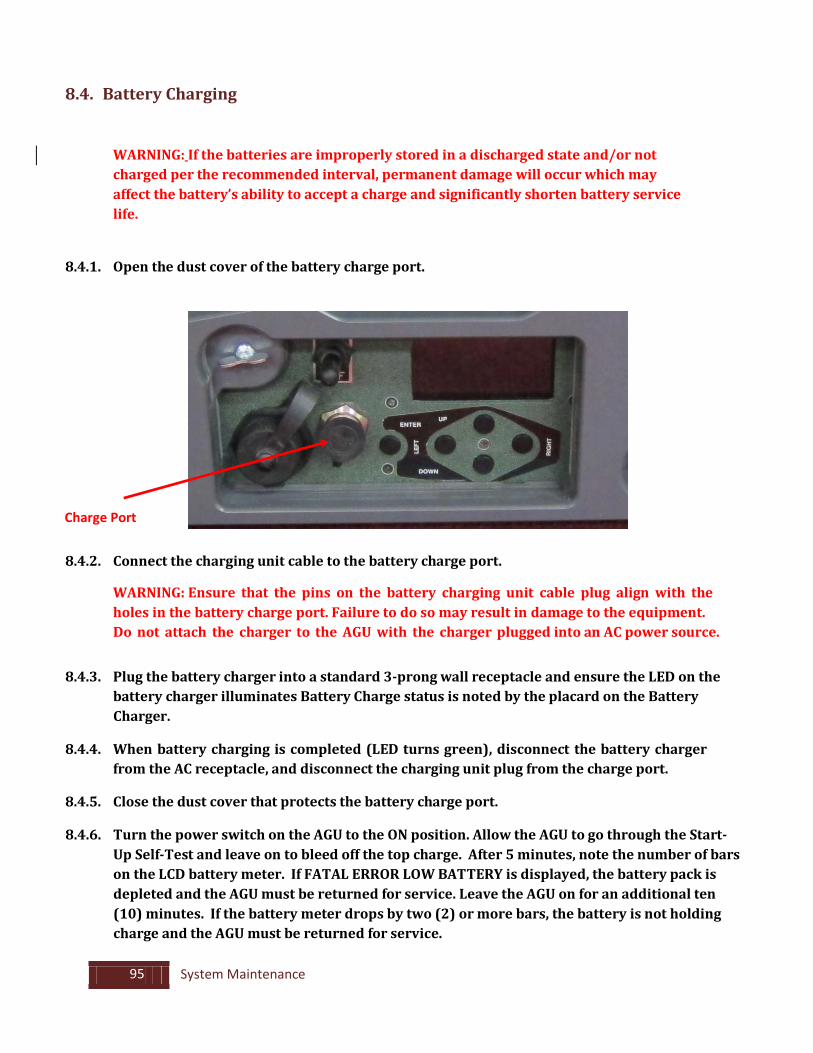
8.4. Battery Charging
WARNING: If the batteries are improperly stored in a discharged state and/or not charged per the recommended interval, permanent damage will occur which may affect the battery’s ability to accept a charge and significantly shorten battery service life.
8.4.1. Open the dust cover of the battery charge port.
Charge Port
8.4.2. Connect the charging unit cable to the battery charge port.
WARNING: Ensure that the pins on the battery charging unit cable plug align with the holes in the battery charge port. Failure to do so may result in damage to the equipment. Do not attach the charger to the AGU with the charger plugged into an AC power source.
8.4.3. Plug the battery charger into a standard 3-prong wall receptacle and ensure the LED on the battery charger illuminates Battery Charge status is noted by the placard on the Battery Charger.
8.4.4. When battery charging is completed (LED turns green), disconnect the battery charger
from the AC receptacle, and disconnect the charging unit plug from the charge port.
8.4.5. Close the dust cover that protects the battery charge port.
8.4.6. Turn the power switch on the AGU to the ON position. Allow the AGU to go through the Start-Up Self-Test and leave on to bleed off the top charge. After 5 minutes, note the number of bars on the LCD battery meter. If FATAL ERROR LOW BATTERY is displayed, the battery pack is depleted and the AGU must be returned for service. Leave the AGU on for an additional ten (10) minutes. If the battery meter drops by two (2) or more bars, the battery is not holding charge and the AGU must be returned for service.

96 System Maintenance
8.4.7. Turn the AGU power switch to the OFF position.
NOTE: A charging unit is provided. The unit plugs into a standard 3-prong receptacle and is compatible with 100-120VAC/200-240VAC 50/60Hz supply voltages.
If using the Charging Unit in a foreign country where a standard 3-prong U.S. receptacle is not available, an adapter may be necessary for the plug at the end of the power cord to permit the plug to be inserted into the AC receptacle.
97 Instructions, Quick Start and Troubleshooting for the CPadS AGU
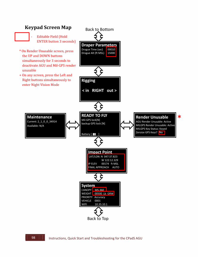
9. Instructions, Quick Start and Troubleshooting For The CPadS AGU 9.1. Operator Instructions for the CPadS AGU SOFTWARE SCREENS From the Startup screen, navigation of the screens is accomplished by pressing the UP or DOWN button to display the adjacent screen. The Maintenance and Render Unusable screens are accessible by pushing the LEFT or RIGHT button from the Startup Screen. The following screens are available after the CPadS has booted up: Startup (Ready to Fly) Rigging System Impact Point Draper Parameters Render Unusable Maintenance NIGHT VISION MODE The LCD screen can be set for compatibility with night vision equipment. Night Vision Mode is engaged by holding down the LEFT and RIGHT keypad buttons simultaneously for 3 seconds at any time that the CPadS is powered on. Night Vision Mode turns off the LCD backlight allowing direct viewing of the LCD screen is impairing the viewer or blinding the NVGs. Night Vision Mode can be disengaged by holding LEFT and RIGHT keypad buttons simultaneously for 3 seconds for a second time. The CPadS can also be reset to the normal operating display by turning the power switch off, then on. NOTE: Red boxes designate editable fields below. To edit a field, hold Enter button for three seconds. Software will ask for a second confirmation key press (Enter button) to complete the change being requested. The screens presented are generally representative but may vary depending on specific features and configurations possible with the system.
98 Instructions, Quick Start and Troubleshooting for the CPadS AGU
Keypad Screen Map
- Editable Field (Hold ENTER button 3 seconds)
* On Render Unusable screen, press
the UP and DOWN buttons simultaneously for 3 seconds to deactivate AGU and Mil-GPS render unusable
+ On any screen, press the Left and Right buttons simultaneously to enter Night Vision Mode
Render Unusable AGU Render Unusable: Active MILGPS Render Unusable: Active MILGPS Key Status: Keyed Zeroize GPS Keys? No
Back to Bottom
Back to Top
Rigging < in RIGHT out >
Maintenance Current: 2_1_0_0_34914 Available: N/Alable
READY TO FLY Mil-GPS lock[N] backup GPS lock [N] Battery [ ]
*
System CANOPY MS-360 WEIGHT 00500 Lb GRW PRIORITY Accuracy VEHICLE 0001 WIFI 10.35.10.1
Draper Parameters Drogue Time (sec) 00010 Drogue Alt (ft MSL) 15000
Impact Point LAT/LON: N 047:37.823 W 122:12.329 IP ELEV 00174 ft MSL FINAL APPROACH AUTO
99 Instructions, Quick Start and Troubleshooting for the CPadS AGU
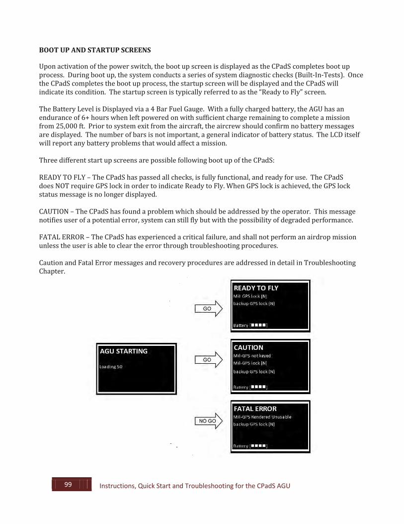
BOOT UP AND STARTUP SCREENS Upon activation of the power switch, the boot up screen is displayed as the CPadS completes boot up process. During boot up, the system conducts a series of system diagnostic checks (Built-In-Tests). Once the CPadS completes the boot up process, the startup screen will be displayed and the CPadS will indicate its condition. The startup screen is typically referred to as the “Ready to Fly” screen. The Battery Level is Displayed via a 4 Bar Fuel Gauge. With a fully charged battery, the AGU has an endurance of 6+ hours when left powered on with sufficient charge remaining to complete a mission from 25,000 ft. Prior to system exit from the aircraft, the aircrew should confirm no battery messages are displayed. The number of bars is not important, a general indicator of battery status. The LCD itself will report any battery problems that would affect a mission. Three different start up screens are possible following boot up of the CPadS: READY TO FLY – The CPadS has passed all checks, is fully functional, and ready for use. The CPadS does NOT require GPS lock in order to indicate Ready to Fly. When GPS lock is achieved, the GPS lock status message is no longer displayed. CAUTION – The CPadS has found a problem which should be addressed by the operator. This message notifies user of a potential error, system can still fly but with the possibility of degraded performance. FATAL ERROR – The CPadS has experienced a critical failure, and shall not perform an airdrop mission unless the user is able to clear the error through troubleshooting procedures. Caution and Fatal Error messages and recovery procedures are addressed in detail in Troubleshooting Chapter.
100 Instructions, Quick Start and Troubleshooting for the CPadS AGU
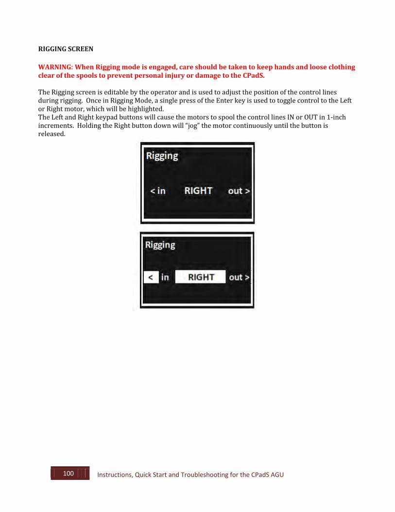
RIGGING SCREEN WARNING: When Rigging mode is engaged, care should be taken to keep hands and loose clothing clear of the spools to prevent personal injury or damage to the CPadS. The Rigging screen is editable by the operator and is used to adjust the position of the control lines during rigging. Once in Rigging Mode, a single press of the Enter key is used to toggle control to the Left or Right motor, which will be highlighted. The Left and Right keypad buttons will cause the motors to spool the control lines IN or OUT in 1-inch increments. Holding the Right button down will “jog” the motor continuously until the button is released.
101 Instructions, Quick Start and Troubleshooting for the CPadS AGU
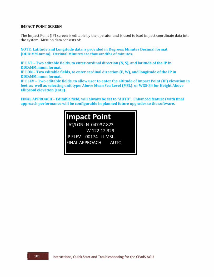
IMPACT POINT SCREEN The Impact Point (IP) screen is editable by the operator and is used to load impact coordinate data into the system. Mission data consists of: NOTE: Latitude and Longitude data is provided in Degrees: Minutes Decimal format [DDD:MM.mmm]. Decimal Minutes are thousandths of minutes. IP LAT – Two editable fields, to enter cardinal direction (N, S), and latitude of the IP in DDD:MM.mmm format. IP LON – Two editable fields, to enter cardinal direction (E, W), and longitude of the IP in DDD:MM.mmm format. IP ELEV – Two editable fields, to allow user to enter the altitude of Impact Point (IP) elevation in feet, as well as selecting unit type: Above Mean Sea Level (MSL), or WGS-84 for Height Above Ellipsoid elevation (HAE). FINAL APPROACH – Editable field, will always be set to “AUTO”. Enhanced features with final approach performance will be configurable in planned future upgrades to the software.
Impact Point
LAT/LON: N 047:37.823 W 122:12.329 IP ELEV 00174 ft MSL FINAL APPROACH AUTO
102 Instructions, Quick Start and Troubleshooting for the CPadS AGU
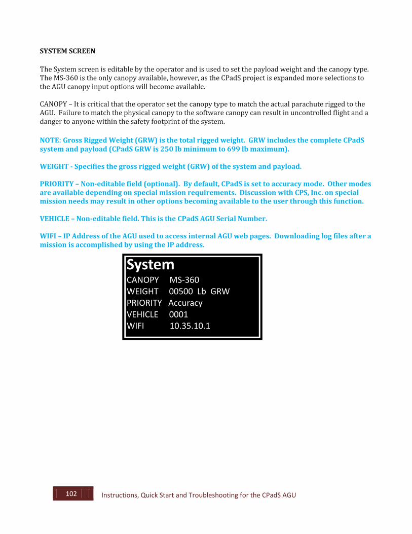
SYSTEM SCREEN The System screen is editable by the operator and is used to set the payload weight and the canopy type. The MS-360 is the only canopy available, however, as the CPadS project is expanded more selections to the AGU canopy input options will become available. CANOPY – It is critical that the operator set the canopy type to match the actual parachute rigged to the AGU. Failure to match the physical canopy to the software canopy can result in uncontrolled flight and a danger to anyone within the safety footprint of the system. NOTE: Gross Rigged Weight (GRW) is the total rigged weight. GRW includes the complete CPadS system and payload (CPadS GRW is 250 lb minimum to 699 lb maximum). WEIGHT - Specifies the gross rigged weight (GRW) of the system and payload. PRIORITY – Non-editable field (optional). By default, CPadS is set to accuracy mode. Other modes are available depending on special mission requirements. Discussion with CPS, Inc. on special mission needs may result in other options becoming available to the user through this function. VEHICLE – Non-editable field. This is the CPadS AGU Serial Number. WIFI – IP Address of the AGU used to access internal AGU web pages. Downloading log files after a mission is accomplished by using the IP address.
System
CANOPY MS-360 WEIGHT 00500 Lb GRW PRIORITY Accuracy VEHICLE 0001 WIFI 10.35.10.1
103 Instructions, Quick Start and Troubleshooting for the CPadS AGU
DRAPER PARAMETERS
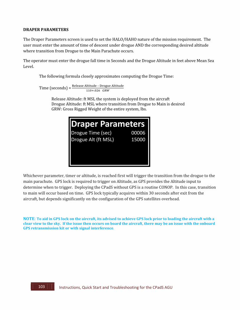
The Draper Parameters screen is used to set the HALO/HAHO nature of the mission requirement. The user must enter the amount of time of descent under drogue AND the corresponding desired altitude where transition from Drogue to the Main Parachute occurs.
The operator must enter the drogue fall time in Seconds and the Drogue Altitude in feet above Mean Sea Level.
The following formula closely approximates computing the Drogue Time:
Time (seconds) = Release Altitude – Drogue Altitude110+.026×𝐺𝐺𝐺𝐺𝐺𝐺
Release Altitude: ft MSL the system is deployed from the aircraft Drogue Altitude: ft MSL where transition from Drogue to Main is desired GRW: Gross Rigged Weight of the entire system, lbs.
Whichever parameter, timer or altitude, is reached first will trigger the transition from the drogue to the main parachute. GPS lock is required to trigger on Altitude, as GPS provides the Altitude input to determine when to trigger. Deploying the CPadS without GPS is a routine CONOP. In this case, transition to main will occur based on time. GPS lock typically acquires within 30 seconds after exit from the aircraft, but depends significantly on the configuration of the GPS satellites overhead.
NOTE: To aid in GPS lock on the aircraft, its advised to achieve GPS lock prior to loading the aircraft with a clear view to the sky. If the issue then occurs on board the aircraft, there may be an issue with the onboard GPS retransmission kit or with signal interference.
Draper Parameters
Drogue Time (sec) 00006 Drogue Alt (ft MSL) 15000
104 Instructions, Quick Start and Troubleshooting for the CPadS AGU
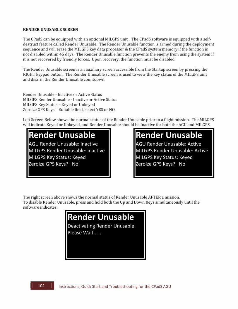
RENDER UNUSABLE SCREEN The CPadS can be equipped with an optional MILGPS unit . The CPadS software is equipped with a self-destruct feature called Render Unusable. The Render Unusable function is armed during the deployment sequence and will erase the MILGPS key data processor & the CPadS system memory if the function is not disabled within 45 days. The Render Unusable function prevents the enemy from using the system if it is not recovered by friendly forces. Upon recovery, the function must be disabled. The Render Unusable screen is an auxiliary screen accessible from the Startup screen by pressing the RIGHT keypad button. The Render Unusable screen is used to view the key status of the MILGPS unit and disarm the Render Unusable countdown. Render Unusable - Inactive or Active Status MILGPS Render Unusable - Inactive or Active Status MILGPS Key Status – Keyed or Unkeyed Zeroize GPS Keys – Editable field, select YES or NO. Left Screen Below shows the normal status of the Render Unusable prior to a flight mission. The MILGPS will indicate Keyed or Unkeyed, and Render Unusable should be Inactive for both the AGU and MILGPS.
The right screen above shows the normal status of Render Unusable AFTER a mission. To disable Render Unusable, press and hold both the Up and Down Keys simultaneously until the software indicates:
Render Unusable
AGU Render Unusable: inactive MILGPS Render Unusable: inactive MILGPS Key Status: Keyed Zeroize GPS Keys? No
Render Unusable
AGU Render Unusable: Active MILGPS Render Unusable: Active MILGPS Key Status: Keyed Zeroize GPS Keys? No
Render Unusable
Deactivating Render Unusable Please Wait . . .
105 Instructions, Quick Start and Troubleshooting for the CPadS AGU
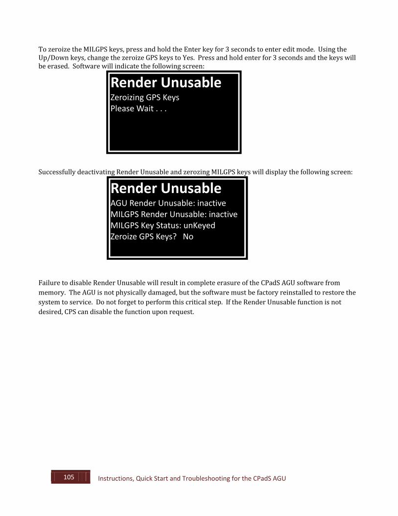
To zeroize the MILGPS keys, press and hold the Enter key for 3 seconds to enter edit mode. Using the Up/Down keys, change the zeroize GPS keys to Yes. Press and hold enter for 3 seconds and the keys will be erased. Software will indicate the following screen:
Successfully deactivating Render Unusable and zerozing MILGPS keys will display the following screen:
Failure to disable Render Unusable will result in complete erasure of the CPadS AGU software from memory. The AGU is not physically damaged, but the software must be factory reinstalled to restore the system to service. Do not forget to perform this critical step. If the Render Unusable function is not desired, CPS can disable the function upon request.
Render Unusable
Zeroizing GPS Keys Please Wait . . .
Render Unusable
AGU Render Unusable: inactive MILGPS Render Unusable: inactive MILGPS Key Status: unKeyed Zeroize GPS Keys? No
106 Instructions, Quick Start and Troubleshooting for the CPadS AGU
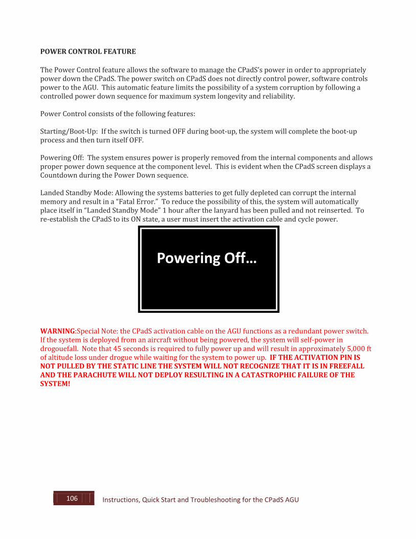
POWER CONTROL FEATURE The Power Control feature allows the software to manage the CPadS’s power in order to appropriately power down the CPadS. The power switch on CPadS does not directly control power, software controls power to the AGU. This automatic feature limits the possibility of a system corruption by following a controlled power down sequence for maximum system longevity and reliability. Power Control consists of the following features: Starting/Boot-Up: If the switch is turned OFF during boot-up, the system will complete the boot-up process and then turn itself OFF. Powering Off: The system ensures power is properly removed from the internal components and allows proper power down sequence at the component level. This is evident when the CPadS screen displays a Countdown during the Power Down sequence. Landed Standby Mode: Allowing the systems batteries to get fully depleted can corrupt the internal memory and result in a “Fatal Error.” To reduce the possibility of this, the system will automatically place itself in “Landed Standby Mode” 1 hour after the lanyard has been pulled and not reinserted. To re-establish the CPadS to its ON state, a user must insert the activation cable and cycle power.
WARNING:Special Note: the CPadS activation cable on the AGU functions as a redundant power switch. If the system is deployed from an aircraft without being powered, the system will self-power in drogouefall. Note that 45 seconds is required to fully power up and will result in approximately 5,000 ft of altitude loss under drogue while waiting for the system to power up. IF THE ACTIVATION PIN IS NOT PULLED BY THE STATIC LINE THE SYSTEM WILL NOT RECOGNIZE THAT IT IS IN FREEFALL AND THE PARACHUTE WILL NOT DEPLOY RESULTING IN A CATASTROPHIC FAILURE OF THE SYSTEM!
Powering Off…
107 Instructions, Quick Start and Troubleshooting for the CPadS AGU
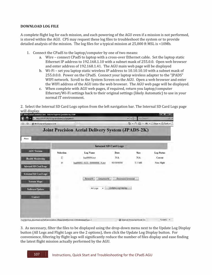
DOWNLOAD LOG FILE A complete flight log for each mission, and each powering of the AGU even if a mission is not performed, is stored within the AGU. CPS may request these log files to troubleshoot the system or to provide detailed analysis of the mission. The log files for a typical mission at 25,000 ft MSL is <10Mb.
1. Connect the CPadS to the laptop/computer by one of two means: a. Wire – connect CPadS to laptop with a cross-over Ethernet cable. Set the laptop static
Ethernet IP address to 192.168.1.10 with a subnet mask of 255.0.0. Open web browser and enter address of 192.168.1.41. The AGU main web page will be displayed
b. Wi-Fi – set you laptop static wireless IP address to 10.10.10.10 with a subnet mask of 255.0.0.0. Power on the CPadS. Connect your laptop wireless adapter to the “JPADS” WIFI network. Scroll to the System Screen on the AGU. Open a web browser and enter the WIFI address of the AGU into the web browser. The AGU web page will be displayed.
c. When complete with AGU web pages, if required, return you laptop/computer Ethernet/Wi-Fi settings back to their original settings (likely Automatic) to use in your normal IT environment.
2. Select the Internal SD Card Logs option from the left navigation bar. The Internal SD Card Logs page will display.
3. As necessary, filter the files to be displayed using the drop-down menu next to the Update Log Display button (All Logs and Flight Logs are the 2 options), then click the Update Log Display button. For convenience, filtering by flight logs will significantly reduce the number of files display and ease finding the latest flight mission actually performed by the AGU.
108 Instructions, Quick Start and Troubleshooting for the CPadS AGU
When the AGU has GPS lock, each log file name will contain the date within the log file name to ease finding log files needed for download. 4. Click the appropriate boxes to check the desired file(s) or use the “Select All” button. 5. Click the “Download Selected” button. A window will display requesting the location to save the files. 6. Click the “Save” button, then navigate to the desired file save location.
A. Alternative method is to individually right click the log file name and selecting “Save As” option.
7. Disconnect the Ethernet cable from the laptop and the CPadS (as required). 9. Power off the CPadS.
109 Instructions, Quick Start and Troubleshooting for the CPadS AGU
9.2. Quick Start Guide: Programming the CPadS AGU NOTE: When the CPadS is powered up on the ground, the CPadS activation cable must be fully inserted to prevent the system from entering autonomous flight mode. This chapter assumes that MILGPS Keys have been loaded if applicable, that Terrain Data has been loaded if applicable, and that the following mission data is available to the user: Impact Point Latitude, Impact Point Longitude, Impact Point Elevation, and Payload Weight. Prior to beginning this procedure, familiarize yourself with the following CPadS keypad interface commands: Hold ENTER for 3 seconds to enter edit mode. Use LEFT/RIGHT buttons to move cursor left and right. Use UP/DOWN buttons to change highlighted values. Use ENTER to move to next line. Hold ENTER for 3 seconds to exit edit mode and save new mission data.
PROGRAMMING THE CPadS FOR MISSION READINESS
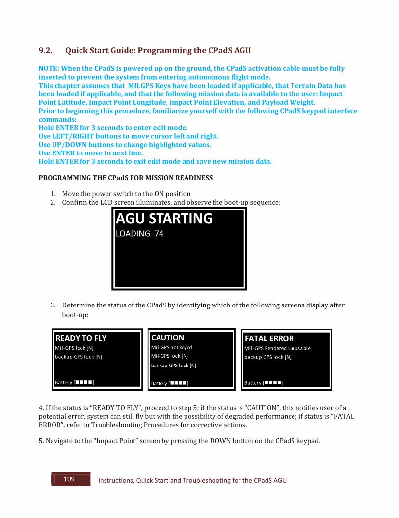
1. Move the power switch to the ON position 2. Confirm the LCD screen illuminates, and observe the boot-up sequence:
3. Determine the status of the CPadS by identifying which of the following screens display after boot-up:
4. If the status is “READY TO FLY”, proceed to step 5; if the status is “CAUTION”, this notifies user of a potential error, system can still fly but with the possibility of degraded performance; if status is “FATAL ERROR”, refer to Troubleshooting Procedures for corrective actions. 5. Navigate to the “Impact Point” screen by pressing the DOWN button on the CPadS keypad.
AGU STARTING LOADING 74
110 Instructions, Quick Start and Troubleshooting for the CPadS AGU
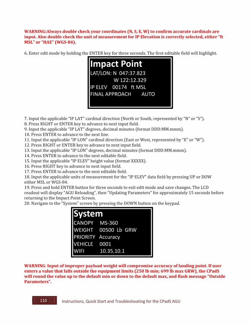
WARNING:Always double check your coordinates (N, S, E, W) to confirm accurate cardinals are input. Also double check the unit of measurement for IP Elevation is correctly selected, either “ft MSL” or “HAE” (WGS-84). 6. Enter edit mode by holding the ENTER key for three seconds. The first editable field will highlight.
7. Input the applicable “IP LAT” cardinal direction (North or South, represented by “N” or “S”). 8. Press RIGHT or ENTER key to advance to next input field. 9. Input the applicable “IP LAT” degrees, decimal minutes (format DDD:MM.mmm). 10. Press ENTER to advance to the next line. 11. Input the applicable “IP LON” cardinal direction (East or West, represented by “E” or “W”). 12. Press RIGHT or ENTER key to advance to next input field. 13. Input the applicable “IP LON” degrees, decimal minutes (format DDD:MM.mmm). 14. Press ENTER to advance to the next editable field. 15. Input the applicable “IP ELEV” height value (format XXXXX). 16. Press RIGHT key to advance to next input field. 17. Press ENTER to advance to the next editable field. 18. Input the applicable units of measurement for the “IP ELEV” data field by pressing UP or DOW either MSL or WGS-84. 19. Press and hold ENTER button for three seconds to exit edit mode and save changes. The LCD readout will display “AGU Reloading”, then “Updating Parameters” for approximately 15 seconds before returning to the Impact Point Screen. 20. Navigate to the “System” screen by pressing the DOWN button on the keypad.
WARNING: Input of improper payload weight will compromise accuracy of landing point. If user enters a value that falls outside the equipment limits (250 lb min; 699 lb max GRW), the CPadS will round the value up to the default min or down to the default max, and flash message “Outside Parameters”.
Impact Point
LAT/LON: N 047:37.823 W 122:12.329 IP ELEV 00174 ft MSL FINAL APPROACH AUTO
System
CANOPY MS-360 WEIGHT 00500 Lb GRW PRIORITY Accuracy VEHICLE 0001 WIFI 10.35.10.1

111 Instructions, Quick Start and Troubleshooting for the CPadS AGU
21. Enter edit mode by holding the ENTER key for three seconds. 22. Input the “Weight” weight for the upcoming mission. This value should be the gross weight of the payload, which includes the CPadS and all rigging materials (honeycomb, harness, etc.). 23. Press and hold ENTER button for three seconds to exit edit mode and save changes. The LCD readout will display “AGU Reloading”, then “Updating Parameters” for approximately 15 seconds before returning to the System screen. 24. Navigate back to the Startup Screen to ensure that the CPadS is “READY TO FLY”, and that no Caution or Error messages appear. If such messages appear, refer to Troubleshooting. 25. Power off the CPadS NOTE: To aid in GPS lock on the aircraft, its advised to achieve GPS lock prior to loading the aircraft with a clear view to the sky. If the issue then occurs on board the aircraft, there may be an issue with the onboard GPS retransmission kit or with signal interference.
112 Instructions, Quick Start and Troubleshooting for the CPadS AGU
9.3. Troubleshooting Procedures for CPadS AGU GPS LOCK [N] SYMPTOM CPadS displays the message “MILGPS lock [N]” and/or “Back-up GPS lock [N].” CONDITION GPS does not have MILGPS and/or Back-up GPS lock. CORRECTIVE ACTION STEP 1. Ensure that one of the following conditions are met: the CPadS has an unobstructed view of the sky, or (while aboard aircraft) that the onboard GPS retransmission kit is working. STEP 2. Wait up to 15 min for both GPS receivers to achieve lock. STEP 3. Cycle the CPadS Power OFF for 30 seconds and then ON. STEP 4. If error remains (while aboard aircraft) remove from aircraft and repeat steps 2 and 3 with a clear view of the sky. STEP 5. If error remains, return the AGU to manufacturer. MEMORY CARD ALMOST FULL SYMPTOM CPadS displays the message “CAUTION, Memory Card Almost Full.” CONDITION CPadS senses that the SD Card is at 90% of its memory capacity. CORRECTIVE ACTION NOTE: CPadS automatically deletes oldest non-flight log files before starting to delete flight log files or terrain data. STEP 1. If additional space is required, delete unnecessary log files within the AGU via the on-board web pages. NO IMPACT POINT PROGRAMMED SYMPTOM CPadS displays the message "FATAL ERROR No IP Programmed." CONDITION After the systems lands it deletes the "intended impact point" coordinates from the AGU. CORRECTIVE ACTION STEP 1. Press down once to navigate to Impact Point screen. Enter edit mode by holding Enter for three seconds. STEP 2. Press the Right button to navigate to the first digit (should be zero). Press up or down to change the zero to any other value. Hold the Enter button for three seconds to exit edit mode. System will refresh.
113 Instructions, Quick Start and Troubleshooting for the CPadS AGU
STEP 3. Press up to navigate back to the Startup screen. Confirm that “FATAL ERROR No IP Programmed” is no longer present. BATTERY TROUBLESHOOTING SYMPTOM LCD displays “CAUTION: LOW BATTERY” or “FATAL ERROR: LOW BATTERY”. CONDITION Battery lacks a full charge. “CAUTION” indicates that one mission is possible before battery is depleted of existing charge, “FATAL ERROR” indicates that mission is not possible. CORRECTIVE ACTION STEP 1. Charge the battery for 2.5 hours or until the charger displays a green LED. STEP 2. Power on CPadS and wait 10 minutes for battery voltage to stabilize. STEP 3. If LCD battery indication bars drop by (2) or more bars within 10 minutes, or if Caution or Fatal Error are still present, complete Charging Unit Troubleshooting. If Charging Unit is determined to be good, return the CPadS to CPS for battery replacement CHARGING UNIT TROUBLESHOOTING SYMPTOM 2.5 hours of charging does not result in fully charged battery. CONDITION Either the Charging Unit is improperly attached or is no longer serviceable. CORRECTIVE ACTION STEP 1. Ensure that the charging unit is firmly plugged into a known good outlet. STEP 2. Disconnected from CPadS, confirm that a green LED light is illuminated. If a green LED is not illuminated, replace charger. STEP 3. Power on the CPadS and observe the Battery Gauge. Plug the charging unit into the CPadS and see that the Battery Gauge increases. STEP 4. If the battery gauge increases, the charger is confirmed to be functioning and the battery is at end of life. STEP 5. If the battery gauge does not change, the charger is malfunctioning and must be replaced. CPadS FATAL ERROR SYMPTOM CPadS displays the message “FATAL ERROR System Fault.” CONDITION Upon CPadS power up, the CPadS Internal Processor has detected a problem with one or more CPadS processes. CORRECTIVE ACTION STEP 1. Cycle the CPadS Power OFF for 5 or more seconds and then ON. STEP 2. If “FATAL ERROR System Fault” remains, contact CPS for advanced troubleshooting procedures.
114 Instructions, Quick Start and Troubleshooting for the CPadS AGU
CPadS WILL NOT DISPLAY “READY TO FLY” SYMPTOM CPadS LCD never displays “Ready To Fly” screen. CONDITION LCD Screen stops refreshing timer during boot up sequence and never displays “Ready To Fly” screen. CORRECTIVE ACTION STEP 1. Cycle the CPadS Power OFF for 5 or more seconds and then ON. STEP 2. If “Ready To Fly” screen does not display, contact CPS for advanced troubleshooting procedures. . CPadS CONTROL LINE SPOOLS SYMPTOM Control line spools move without being commanded to do so. CONDITION Activation cable is damaged or improperly inserted or activation block could be damaged. CORRECTIVE ACTION STEP 1. Ensure that the CPadS activation cable is serviceable and properly inserted. The end of the cable should be visible at its exit point at the bottom of the activation block. STEP 2. If cable appears damaged, replace cable. STEP 3. Cycle the CPadS Power OFF for 5 or more seconds and then ON. STEP 4. If error remains, contact CPS for service. SYMPTOM Control line spools nonresponsive in Rigging Mode. CONDITION Upon engaging Rigging Mode and commanding movement, the control line spools do not move or move slowly. CORRECTIVE ACTION STEP 1. Cycle the CPadS Power OFF for 5 or more seconds and then ON. STEP 2. If error remains, contact CPS for service.
CPadS EXIT WEIGHT
SYMPTOM CPadS displays the message “CAUTION, Exit weight outside limits.” CONDITION The gross rigged weight is outside the permissible range of 250 lb to 699 lbs. If weight entered is below 250 lb, the exit weight will be automatically reprogrammed by the CPadS to the minimum rigged weight of 250 lb If weight entered is above 699 lb, the exit weight will be automatically reprogrammed by the CPadS to the maximum rigged weight of 699 lbs. As a result, the system will fly with potentially degraded performance relative to the difference between the actual rigged weight and the automatically programmed weight.
115 Instructions, Quick Start and Troubleshooting for the CPadS AGU
CORRECTIVE ACTION STEP 1. Program suitable payload weight as follows: a. Press the UP button until reaching the “System” screen. b. Press the ENTER key twice. The cursor should be on the first digit of WEIGHT. c. Using the RIGHT key, move the cursor across to the appropriate digit and use the UP and DOWN keys to set the proper gross rigged weight. d. Once the proper gross rigged weight has been programmed, press and hold the ENTER key for 3 seconds until the digits are unhighlighted. e. Press the UP key until reaching the READY TO FLY screen. MILGPS SYMPTOM CPadS displays the message “CAUTION, MILGPS not keyed.” CONDITION A valid MILGPS key is not programmed in the AGU.. CORRECTIVE ACTION STEP 1. Key the MILGPS using unit procedures for the key fill device. STEP 2. Cycle the CPadS power OFF for 5 or more seconds then ON. Check if problem has been resolved. If so, resume normal operation. STEP 3. If error remains after re-keying the MILGPS, contact CPS for service. SYMPTOM CPadS displays the MILGPS Status message “CAUTION, RENDER UNUSABLE Active for MM.DD.YYYY.” CONDITION Render Unusable function (which deletes the MILGPS keys at the end of 45 days, and disables the CPadS software), is active. CORRECTIVE ACTION STEP 1. Perform “DISARM RENDER UNUSABLE” procedure. STEP 2. Cycle the CPadS Power OFF for 5 or more seconds and then ON. STEP 3. If error remains, contact CPS. for service. RENDERED UNUSABLE AVIONICS MODULE SYMPTOM CPadS displays Render Unusable status message “FATAL ERROR, AGU Rendered Unusable.” CONDITION RENDER UNUSABLE function was not deactivated within 45 days. CORRECTIVE ACTION Return CPadS to CPS for reprogramming. Depending on IT infrastructure, CPS may be able to restore the AGU to proper function via remote support.
116 Instructions, Quick Start and Troubleshooting for the CPadS AGU
CPadS KEYPAD SYMPTOM CPadS LCD cursor is unresponsive when pressing keys in edit mode. CONDITION The CPadS keypad is damaged or impaired. CORRECTIVE ACTION STEP 1. Check for debris around the buttons and clean as necessary. Press keypad buttons to see if normal operations are restored. STEP 2. If problem persists, cycle the CPadS Power OFF for 30 seconds and then ON. STEP 3. If the LCD cursor remains unresponsive, contact CPS. for service. NOTE: Do Not Clean AGU with High-Pressure Water. Hand Clean as required using normal detergents with low-pressure water.
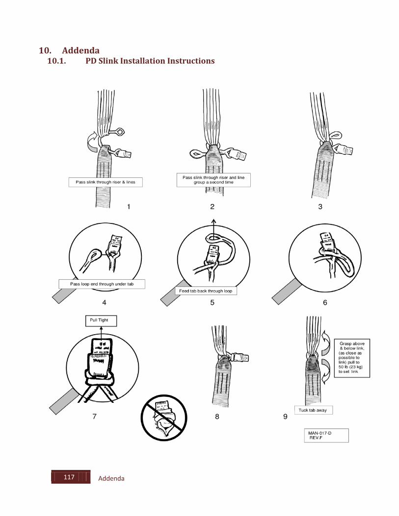
117 Addenda
10. Addenda 10.1. PD Slink Installation Instructions
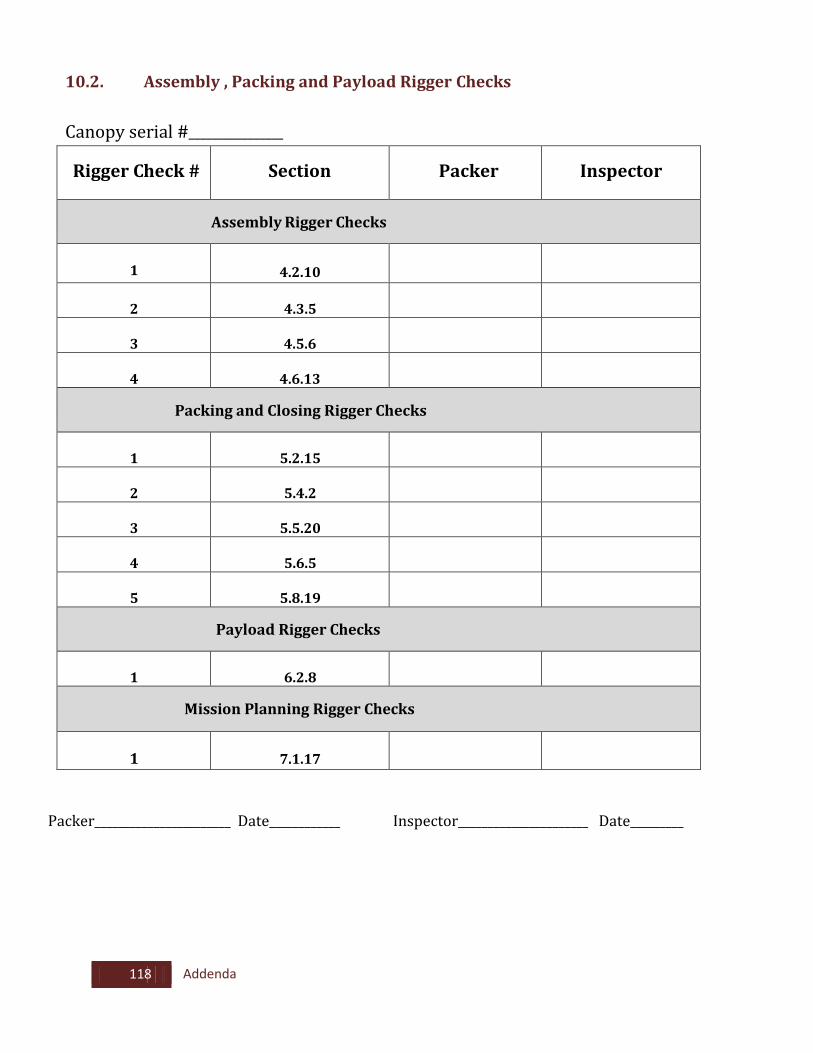
118 Addenda
10.2. Assembly , Packing and Payload Rigger Checks Canopy serial #________________
Rigger Check #
Section
Packer
Inspector
Assembly Rigger Checks
1
4.2.10
2
4.3.5
3
4.5.6
4
4.6.13
Packing and Closing Rigger Checks
1
5.2.15
2
5.4.2
3
5.5.20
4
5.6.5
5
5.8.19
Payload Rigger Checks
1
6.2.8
Mission Planning Rigger Checks
1
7.1.17
Packer_______________________ Date____________ Inspector______________________ Date_________