HALFEN HBT REBEND CONNECTION HBT...
16
Complies with ACI 318-14 HBT 16-US HALFEN HBT REBEND CONNECTION CONCRETE
Transcript of HALFEN HBT REBEND CONNECTION HBT...

Complies with ACI 318-14
HBT 16-US HALFENHBTREBENDCONNECTION
CONCRETE

Manyadvantageswithoneresult:HALFENprovidessafety,reliabilityandefficiencyforyouandyourcustomers.
HALFEN HBT Rebend ConnectionReinforcement continuity and structural integrity for segmental pours in reinforced concrete structures
The HBT Rebend Connection is cast into the concrete member leaving the reinforcement legs housed inside of the steel casing until the contractor is ready to pour the adjoining member.
HALFEN USA Inc. · PO Box 18687 · San Antonio TX 78218Phone: + 1 800.423.9140 · [email protected] · www.halfenusa.com
▪ Requires complicated and time consuming formwork
▪ Projecting bars create safety hazard▪ Restricts site access▪ Complicated key ways or roughening
of surface required
▪ Accelerates pour schedules▪ Reduces field labor cost▪ No roughening of narrow areas around
and between the reinforcement▪ Simplifies formwork design▪ Improves safety and working access▪ Prevents damage/waste of formwork▪ No post-drilling in concrete areas with
high density of reinforcement
Traditional Concrete Joint
HALFEN HBT Rebend ConnectionHALFEN HBT Rebend Connection

HALFEN HBT REBENd CONNECTION
© 2016 HALFEN · HBT 16-US · www.halfenusa.com
Contents
Product overview 4-5
Rebending of reinforcing steel 6
Application examples 7-8
Product range: Profiles, Variants, Bar Types 9
Standard element single row: HBT 85 and 120, Type 1 + Type 2 10-11
Standard element double row: HBT 120, 150, 190 and 220 12
HBT technical specifications 13
Engineering request form 14
Installation instructions 15
Contact 16
3
© t
omja
sny.
com
HALFEN HBT Rebend Connection
HALFEN HBT REBENd CONNECTION
© 2016 HALFEN · HBT 16-US · www.halfenusa.com
Product overv iew
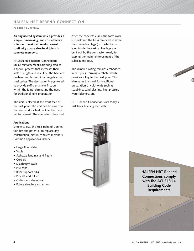
An engineered system which provides a simple, time-saving, and cost-effective solution to maintain reinforcement continuity across structural joints in concrete members.
HALFEN HBT Rebend Connections utilize reinforcement bars subjected to a special process that increases their yield strength and ductility. The bars are pre-bent and housed in a pre-galvanized steel casing. The steel casing is engineered to provide sufficient shear friction within the joint, eliminating the need for traditional joint preparation.
The unit is placed at the front face of the first pour. The unit can be nailed to the formwork or tied back to the main reinforcement. The concrete is then cast.
After the concrete cures, the form work is struck and the lid is removed to reveal the connection legs (or starter bars) lying inside the casing. The legs are bent out by the contractor, ready for lapping the main reinforcement of the subsequent pour.
The dimpled casing remains embedded in first pour, forming a rebate which provides a key to the next pour. This eliminates the need for traditional preparation of cold joints such as scabbling, sand blasting, high-pressure water blasters, etc.
HBT Rebend Connection suits today’s fast track building methods.
ApplicationsSimple to use, the HBT Rebend Connec-tion has the potential to replace any construction joint in concrete members. Common applications include:
• Large floor slabs• Walls• Staircase landings and flights• Corbels• Diaphragm walls• Pile caps• Brick support nibs• Precast and tilt up• Gullies and chambers• Future structure expansion
HALFEN HBT Rebend Connections comply with the ACI 318-14
Building Code Requirements
4

HALFEN HBT REBENd CONNECTION
© 2016 HALFEN · HBT 16-US · www.halfenusa.com
Product overv iew
HALFEN has carefully designed the HBT Rebend Connection to optimize its performance while providing a simple installation. When two concrete structures cast at different times are expected to act in a composite manner, the solution is HALFEN.
Quality Features:Provides the required development length in order for the reinforcing steel to achieve the full tensile capacity.
The profiled back provides an optimal bond and shear transfer to the adjacent concrete member. [The Carrier Casing is left in the concrete ensuring that shear load transfer is maintained.]
Ensures a constant roughened surface along the entire length and width of the joint. [In current construction practices, this result is quite challenging to achieve in addition to being time consuming.]
Ductile reinforcement steel grade allows the bars to be rebent. Damage of the formwork is prevented without compromising the structural integrity of the connection.
Flanges of casing engineered with the strength to minimize deformation, preventing the ingress of concrete into the case.
The geometry of the Cover and Carrier Casing forms a keyway which permanently locks the two pours.
The pre-punched cover simplifies its removal after curing of the concrete.
5
HALFEN HBT REBENd CONNECTION
© 2016 HALFEN · HBT 16-US · www.halfenusa.com
Rebending of re inforc ing s tee l
Reinforcement Bend-abilityThe rebending of the reinforcement was the most critical design aspect of the HBT Rebend Connection taken into consideration. ACI 318 states "Reinforce-ment shall not be field bent, except as shown in the contract documents or permitted by the licensed design pro- fessional". Licensed Professionals can use the HBT Rebend Connection with complete confidence knowing the system utilizes a rebar manufactured using a specialty process that produces reinforcement bars with a high yield strength, high ductility, and excellent fabrication characteristics. The HBT reinforcement bars are certified to meet ASTM A615 but possess higher yield strength and elongation values. This results in excellent bend-ability and rebend-ability of the reinforcement bars.
What are the loading differences between HBT Rebend Connection and traditional loose/unbent rebar?Structural tests showed that the flexural and shear strength of construction joints formed with HBT Rebend Connection are equivalent if not greater than those of traditionally formed construction joints.
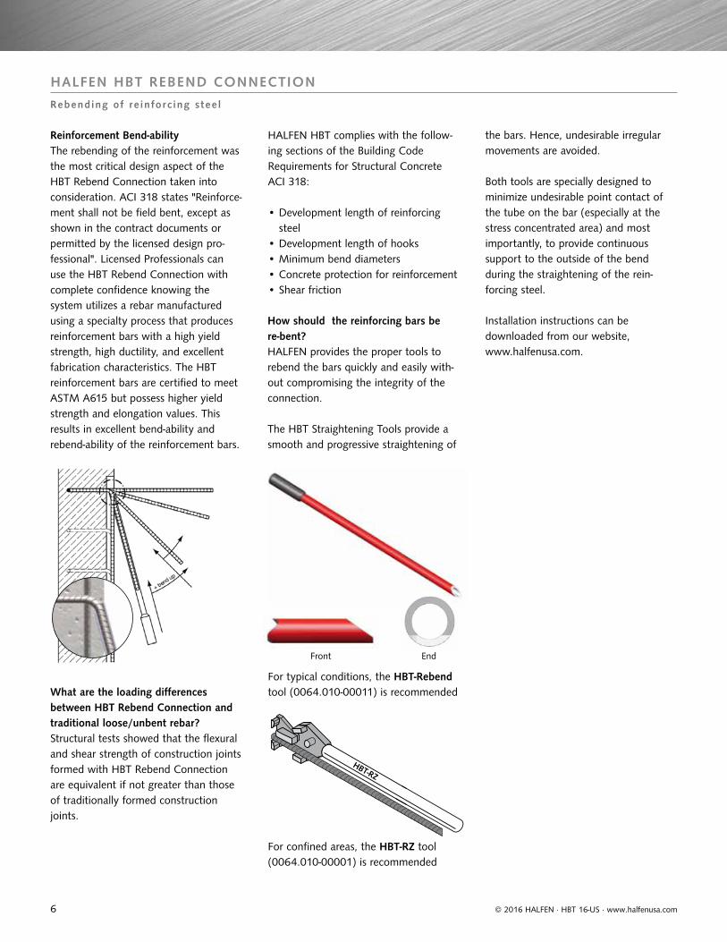
How should the reinforcing bars be re-bent?HALFEN provides the proper tools to rebend the bars quickly and easily with- out compromising the integrity of the connection.
The HBT Straightening Tools provide a smooth and progressive straightening of
the bars. Hence, undesirable irregular movements are avoided.
Both tools are specially designed to minimize undesirable point contact of the tube on the bar (especially at the stress concentrated area) and most importantly, to provide continuous support to the outside of the bend during the straightening of the rein- forcing steel.
Installation instructions can be downloaded from our website, www.halfenusa.com.
For confined areas, the HBT-RZ tool (0064.010-00001) is recommended
HALFEN HBT complies with the follow-ing sections of the Building Code Requirements for Structural Concrete ACI 318:
• Development length of reinforcing steel
• Development length of hooks• Minimum bend diameters• Concrete protection for reinforcement• Shear friction
For typical conditions, the HBT-Rebend tool (0064.010-00011) is recommended
Front End
6

© 2016 HALFEN · HBT 16-US · www.halfenusa.com
HALFEN HBT REBENd CONNECTION
Appl icat ion examples
Corbel connection to concrete wall
Connection of thick slabs or stair-landings to concrete walls,
Stairs flight and landing slab connection to a
concrete wall
Connection of a thick concrete wall with 2 HBT Elements,
Wall connection to concrete ceiling
Vertical section Vertical section
Horizontal section
Vertical section
Horizontal section
Horizontal sectionVertical section
Vertical section
Horizontal section
Vertical section
Wall connection to floor slab
Wall connectionBridge parapet connection to structure
Wall connections to concrete column
Wall corner detail with single or double connection
Connection of precast parapet to balcony
7

HALFEN HBT REBENd CONNECTION
© 2016 HALFEN · HBT 16-US · www.halfenusa.com
Appl icat ion examples
The HALFEN HBT Rebend Connection allows easy and efficient connection of concrete components at different phases of construction. Perfect connections for numerous applications with multiple combinations of rebar types and profile widths. HALFEN HBT Rebend Connections are available in #4 reinforcing steel bar size.
Multifunctional Arena Stadium, Duesseldorf, Germany. The HBT Rebend Connections connect columns, walls, and stairs.
Columns Slabs
Deutsche Post Tower, Bonn, Germany. The HBT Rebend Connections connect stairs and walls.
8

HALFEN HBT REBENd CONNECTION
© 2016 HALFEN · HBT 16-US · www.halfenusa.com
Product range: Prof i les , Var iants , Bar Types
for profile HBT 85 and 120 for profile HBT 120, 150, 190 and 220
a = End distance [in]s = Rebar spacing [in]B = Casing width see standard size [in]L = Element length [in]
Single row double row
a = End distance [in]s = Rebar spacing [in]B = Casing width see standard size [in]L = Element length [in]
Single and double row layouts
7/8"
sa
B
Ls
a
B
7/8"
L
7/8"
yh
lü bh
lü
Bügeltypen
3/4"
Type 5
Type 2
Type 3
Type 4
Standard reinforcing steel bar types
Type 1
HBT Rebend Connection Carrier Casing information
HBT 85 HBT 120 HBT 150 HBT 190 HBT 220
Element width B (in) 3 ₃/₈ 4 ₃/₄ 5 ₇/₈ 7 5/16 8 ₃/₄
Single row connections double row connections
Custom HBT configurations are available to accommodate specific rebar spacings, development lengths, hook lengths, and box lengths. The box width (B), rebar diameter and hole layout (excluding longitudinal spacing) are fixed variables and cannot be modified. To request a custom HBT unit, fill out the Engineering Request Form on Pg 13 and submit to [email protected].
NOTE: custom HBT configurations are available upon request.
ℓdh ℓdh
ℓdhℓdh
ℓdhℓdh
ℓd ℓd
ℓdℓd
ℓdℓd
9

HALFEN HBT REBENd CONNECTION
© 2016 HALFEN · HBT 16-US · www.halfenusa.com
Standard e lement s ing le row
y
Y
a
as
L
ℓdℓdh
Pour 2
Pour 1
d b
HBT 85 and HBT 120
Type 1
HBT Type 1 — System configuration
Element Length L Bar spacing s [in]
No. of bars End distance a [in]
Standard element L = 48 in
8 6 4
10 5 4
HBT Type 1 - Standard element details
designation Article No. dimension of starter bars for element thickness case dimensions
ProfileBar size/
spacing [in] 0054.220**ℓd [in]
*ℓdh [in]
y [in] D1 [in] D2 [in] Width B [in]
Height H1 [in]
Height with cover H2 [in]
85
#4/8 - 00002 19 9 1/2 8 ≥ 11 ≥ 4 3 3/8 1/2 1 1/8
#4/10 - 00003 19 9 1/2 8 ≥ 11 ≥ 4 3 3/8 1/2 1 1/8
#4/12 - 00004 19 9 1/2 8 ≥ 11 ≥ 4 3 3/8 1/2 1 1/8
Profile 0054.240
120
#4/8 - 00003 19 9 1/2 8 ≥ 11 ≥ 5 4 3/4 1/2 1 1/8
#4/10 - 00004 19 9 1/2 8 ≥ 11 ≥ 5 4 3/4 1/2 1 1/8
#4/12 - 00005 19 9 1/2 8 ≥ 11 ≥ 5 4 3/4 1/2 1 1/8
* Standard dimension; based on fʼc = 4000 psi and normal weight concrete** Standard dimension; calculated using ACI 318-14 Eq. 25.4.2.3a, based on ψe=1.0, ψc=1.0, ψs=0.8, fʼc = 4000 psi, Ktr = 0, Type B lap splice and normal
weight concreteReinforcing bar dimensions are out to out of bars.
System:
ℓdh
ℓd
Minimal element length for standard ld
∅ s [in] ld [in]
min. L [in]
No. ofbars
#4
4* 19 40 10
6* 19 36 6
8 19 32 4
10 19 40 4
Minimal element lengths for the rebend connection HBT, position of reinforcement in the metal case
selected ld
25 s
min. L
EPS*-stoppers
s2
* Expanded polystyrene* not available as type 1
s = desired rod spacing
10

HALFEN HBT REBENd CONNECTION
© 2016 HALFEN · HBT 16-US · www.halfenusa.com
a
Y
as
L
description example: HBT 85 - #4/8 - 2 - 48Element length L [in]
Bar type
Bar number/bar spacing s [in]
Profile size
HBT Type 2 — System configuration
Element Length L Bar spacing s [in]
No. of bars End distance a [in]
Standard element L = 48 in
4 12 2
6 8 3
8 6 4
10 5 4
HBT Type 2 - Standard element details
designation Part no. dimension of starter bars for element thickness case dimensions
ProfileBar size/
spacing [in] 0054.220**ℓd [in]
*ℓdh [in]
y [in] D1 [in] D2 [in] Width B [in]
Height H1 [in]
Height with cover H2 [in]
HBT 85
#4/6 - 00011 19 9 1/2 8 ≥ 11 ≥ 4 3 3/8 1/2 1 1/8
#4/8 - 00012 19 9 1/2 8 ≥ 11 ≥ 4 3 3/8 1/2 1 1/8
#4/10 - 00013 19 9 1/2 8 ≥ 11 ≥ 4 3 3/8 1/2 1 1/8
#4/12 - 00014 19 9 1/2 8 ≥ 11 ≥ 4 3 3/8 1/2 1 1/8
Profile 0054.240
HBT 120
#4/4 - 00021 19 9 1/2 8 ≥ 11 ≥ 5 4 3/4 1/2 1 1/8
#4/6 - 00022 19 9 1/2 8 ≥ 11 ≥ 5 4 3/4 1/2 1 1/8
#4/8 - 00023 19 9 1/2 8 ≥ 11 ≥ 5 4 3/4 1/2 1 1/8
#4/10 - 00024 19 9 1/2 8 ≥ 11 ≥ 5 4 3/4 1/2 1 1/8
#4/12 - 00025 19 9 1/2 8 ≥ 11 ≥ 5 4 3/4 1/2 1 1/8
* Standard dimension; based on fʼc = 4000 psi and normal weight concrete** Standard dimension; calculated using ACI 318-14 Eq. 25.4.2.3a, based on ψe=1.0, ψc=1.0, ψs=0.8, fʼc = 4000 psi, Ktr = 0, Type B lap splice and normal
weight concreteReinforcing bar dimensions are out to out of bars.
System:
ℓdh
ℓd
y
ℓdℓdh
Pour 2
Pour 1
Y
HBT 85 and HBT 120
Type 2
Standard e lement s ing le row
11

HALFEN HBT REBENd CONNECTION
© 2016 HALFEN · HBT 16-US · www.halfenusa.com
NOTE: custom HBT configurations are available upon request.
Standard e lement double row
b
as
ab
L
H1
b
ℓdh
D1
H2
ℓd
B D2
System:
HBT 120, HBT 150, HBT 190, and HBT 220
Type 5 double-row connection, standard rebar
Pour 1
Pour 2
HBT Type 5 – System configuration
Element Length L Bar spacing s [in] No. of bars End distance a [in]
standard element L = 48 in
6 8 3
8 6 4
10 5 4
HBT Type 5 - Standard element details
Designation Article No. Connecting reinforcement dimensions For element thickness Case dimensions
ProfileBar size/
spacing [in] 0054.240 **ℓd [in] *ℓdh [in] b [in] D1 [in] D2 [in] Width B [in] Height H1 [in]Height with cover H2 [in]
HBT 120
#4/6 - 00011 19 9 1/2 3 5/8 ≥ 11 ≥ 5 1/2 4 3/4 1/2 1 1/8
#4/8 - 00012 19 9 1/2 3 5/8 ≥ 11 ≥ 5 1/2 4 3/4 1/2 1 1/8
#4/10 - 00013 19 9 1/2 3 5/8 ≥ 11 ≥ 5 1/2 4 3/4 1/2 1 1/8
#4/12 - 00014 19 9 1/2 3 5/8 ≥ 11 ≥ 5 1/2 4 3/4 1/2 1 1/8
Profile 0054.250
HBT 150
#4/6 - 00001 19 9 1/2 4 3/4 ≥ 11 ≥ 6 1/4 5 7/8 1/2 1 1/8
#4/8 - 00002 19 9 1/2 4 3/4 ≥ 11 ≥ 6 1/4 5 7/8 1/2 1 1/8
#4/10 - 00003 19 9 1/2 4 3/4 ≥ 11 ≥ 6 1/4 5 7/8 1/2 1 1/8
#4/12 - 00004 19 9 1/2 4 3/4 ≥ 11 ≥ 6 1/4 5 7/8 1/2 1 1/8
Profile 0054.260
HBT 190
#4/6 - 00001 19 9 1/2 6 1/8 ≥ 11 ≥ 7 5/8 7 3/8 1/2 1 1/8
#4/8 - 00002 19 9 1/2 6 1/8 ≥ 11 ≥ 7 5/8 7 3/8 1/2 1 1/8
#4/10 - 00003 19 9 1/2 6 1/8 ≥ 11 ≥ 7 5/8 7 3/8 1/2 1 1/8
#4/12 - 00004 19 9 1/2 6 1/8 ≥ 11 ≥ 7 5/8 7 3/8 1/2 1 1/8
Profile 0054.270
HBT 220
#4/6 - 00001 19 9 1/2 7 1/2 ≥ 11 ≥ 9 8 3/4 1/2 1 1/8
#4/8 - 00002 19 9 1/2 7 1/2 ≥ 11 ≥ 9 8 3/4 1/2 1 1/8
#4/10 - 00003 19 9 1/2 7 1/2 ≥ 11 ≥ 9 8 3/4 1/2 1 1/8
#4/12 - 00004 19 9 1/2 7 1/2 ≥ 11 ≥ 9 8 3/4 1/2 1 1/8
* Standard dimension; based on fʼc = 4000 psi and normal weight concrete** Standard dimension; calculated using ACI 318-14 Eq. 25.4.2.3a, based on ψe=1.0, ψc=1.0, ψs=0.8, fʼc = 4000 psi, Ktr = 0, Type B lap splice and normal
weight concrete Reinforcing bar dimensions are out to out of bars.
ℓdh
ℓd
d b
12

HALFEN HBT REBENd CONNECTION
© 2016 HALFEN · HBT 16-US · www.halfenusa.com
HBT technica l spec i f i cat ions
• Reinforcing Steel Grade: 60 meets ASTM A615/A615M
• Reinforcing steel size: #4 bar
• Bending diameters meet ACI 318 minimum requirements
• Six standard profiles to suit different structural configurations
• Casing available for single or double bars, 5 standard bar shapes
• Standard element lengths: 48”
• Custom solutions available * Minimum concrete cover “c” must be attained for all steel sections at the construction joint.
Carrier Casing
Starter Rebar ( #4)
HBT Rebend Connection adapted to curved formwork
Caution when working with an angle-grinder! The reinforcing steel bars in the HBT-Casing must not be damaged.
Making incisions in the HBT-CasingUsing an angle-grinder, cut approximately 3/8 in. deep incisions symmetrically into both
sides of the casing at regular intervals. As a result the HBT Housing loses its rigidity,
easing fixing to the formwork. To achieve a better fit to smaller curvature (< 10 ft.), up
to seven incisions per side are possible. After fixing the HBT Housing to the formwork,
cover the incisions with adhesive tape to prevent concrete seeping into the casing.
HBT-Element fitted to a convex curvatureRV radius ≥ ca. 10 ft.; smaller radius is achieved with more incisions.
HBT-Element fitted to a concave curvatureRC radius ≥ ca. 10 ft.; smaller radius is achieved with more incisions.
3/8"
3/8"
3/8" 3/8"
3/8"
3/8"
* c
13

HALFEN HBT REBENd CONNECTION
© 2016 HALFEN · HBT 16-US · www.halfenusa.com
Engineer ing request form
Project information
In order for us to be able to select the most efficient system for your project, please:1. Provide the required information, questions 1 to 5 in the section ’Project Information’.2. Provide the information about the project. 3. Fax to 877-683-4910, e-mail to [email protected], or e-mail to sales representative.
1. Project Name:2. Project Address:3. Location, City: State:4. Company:5. Contact Person:6. Please provide the following HBT information:
Connection ℓd HBT profile
Bar # Bar type Bar spacing s [in]
ldh [in] ld [in] b [in] y [in] Element lengthL [in]
Quantity [ea]
Connection ℓd * Maximum factored shear, Vu (kip/ft)
* Maximum factored moment, Mu (kip/ft)
Connection description
7. Please provide the following project information:
8. Concrete Strength, f'c: [ksi]
* LRFD factored loads
1414

HALFEN HBT REBENd CONNECTION
© 2016 HALFEN · HBT 16-US · www.halfenusa.com
Insta l la t ion inst ruct ions
1.
HBT 8
5# 4
/6
2.
HBT 8
5# 4
/6
HBT 8
5# 4
/6
3.
4.
Fixing the HBT to the formwork
1. Nail (3 nails minimum) the HBT Rebend Connection through the casing to the formwork or alternatively securely tie the projecting anchorage reinforcing bars back to the main reinforcement. When using steel formwork, use suitable fixings. In both cases, the HBT Rebend Connection Box shall be securely fixed to avoid displacement while concrete is poured. The casing shall be tight against the form-work. Pour concrete.
Fixing the HBT to the formwork
Straightening the reinforcing steel
2.
3.
4.
After the concrete has cured, strike the formwork to reveal the cover. Place a wood block in the long groove in the cover and tap lightly with a hammer until the cover loosens.
Use a hammer claw to punch in the perforated hole in the sheet metal cover. Hook the hammer in the hole and pull the lid out to expose the pre-bent bars.
The bars should be straightened only once and gradually. To avoid damage to adjacent concrete, it is prudent to allow a concrete curing period of seven days. See “Straightening of Bars” on page 6 for more information. Once the bars are straightened and aligned, they are ready for lapping with the reinforcement steel (provided by others) of the subsequent reinforced concrete member.
Caution! The edges of the sheet metal are sharp. Protective gloves shall be used while removing the sheet metal cover.
The sheet metal cover can be recycled.
• Straightening of reinforcing steel without an appropriate tool is not recommended.
• do not straighten the reinforcing steel at temperatures lower than 41o Fahrenheit.
8. Concrete Strength, f'c: [ksi]
15

R -
020
- US
- 07/
16
07/
16©
201
6 H
ALF
EN G
mbH
, Ger
man
yap
plie
s al
so t
o co
pyin
g in
ext
ract
s.
CONTACT HALFEN WORLdWIdE
www.HALFEN.com
HALFEN has a global network of Subsidiary Companies to assist you. The main contact information for North America and the European Headquarter is provided below. For a ful l l ist of off ices please visit www.HALFEN.com
HALFEN GmbH shall not accept liability for the accuracy of the information in this publication or for any printing errors.
HALFEN is also represented by distributors in Argentina, Australia, Azerbaijan, Belarus, Brazil, Bulgaria, Chile, China, Colombia, Croatia/Bosnia- Herzegovina/FYROM/Montenegro, Cyprus, Estonia, Greece, Hong Kong, Hungary, India, Indonesia, Ireland, Israel, Japan, Jordan, Kingdom of Saudi-Arabia, Latvia, Lebanon, Lithuania, Luxembourg, Malaysia, Malta, Mexico, New Zealand, Peru, Philippines, Republic of Kazakhstan, Romania, Russia, Serbia, Singapore, Slovenia, Spain, South Korea, Taiwan/ROC, Thailand, Turkey, Ukraine, United Arab Emirates, Uruguay, Vietnam
USA & Mexico HALFEN USA Inc. PO Box 18687San Antonio TX 78218
Phone: +1 800.423.9140 E-Mail: [email protected]: www.halfenusa.com
Fax: +1.877.683.4910
Canada UCC Industries International [Distributor] Units 12 & 13895 Sandy Beach RoadPickering, Ontario, L1W 3N7
Provinces of British Columbia and Alberta: Please contact HALFEN USA Inc.
Phone: +1 905.831.7724 E-Mail: [email protected]: www.ucci.ca
Fax: +1 905.831.5872
Fax: +49 2173 970-123Germany HALFEN GmbH Liebigstrasse 14 40764 Langenfeld
Phone: +49 2173 970-0 E-Mail: [email protected] Web: www.halfen.de