HALFEN FLEXIBLE FRAMING...
48
HALFEN FLEXIBLE FRAMING SYSTEMS FRAMING SYSTEMS MT-FFC 10-US
Transcript of HALFEN FLEXIBLE FRAMING...
HALFEN FLEXIBLE FRAMING SYSTEMS
FRAMING SYSTEMS
MT-FFC 10-US
2 © 2012 HALFEN · MT-FFC 10-US · www.halfenusa.com
HALFEN FRAMING SYSTEMSContents
HALFEN Flexible Framework constructions
- General overview
- Application examples
- System 52 - for heavy duty requirements
- System 41 - for medium duty requirements
- System 36 - for light duty requirements
- System 28 - for light duty requirements
3
4
6
9
14
16
HALFEN Framing System Accessories
- Threaded rods, hexagon head bolts, nuts, washers
- Beam clamp, clamp plate, vibration absorber
- Channel end caps, channel cover strips
- Cantilevers
- Pipe clamp, pipe support
18
20
24
25
31
Appendix
- Pipe weights and support spacing
- Pipe dimension
- Pipe fixings under bridges
- Specification texts
- Addresses/contacts
41
42
44
46
48
3© 2012 HALFEN · MT-FFC 10-US · www.halfenusa.com
HALFEN FRAMING SYSTEMSGeneral Overview
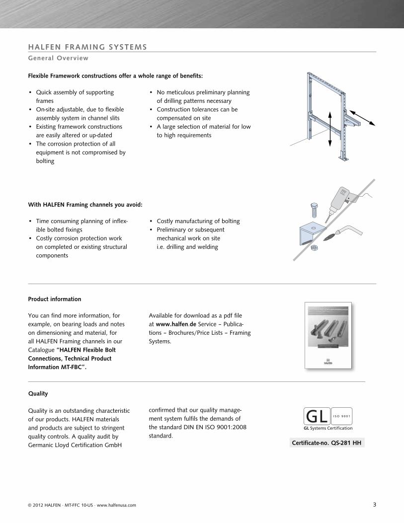
Flexible Framework constructions offer a whole range of benefits:
With HALFEN Framing channels you avoid:
Quality is an outstanding characteristic of our products. HALFEN materials and products are subject to stringent quality controls. A quality audit by Germanic Lloyd Certification GmbH
Quality
Product information
Certificate-no. QS-281 HH
confirmed that our quality manage-ment system fulfils the demands of the standard DIN EN ISO 9001:2008 standard.
You can find more information, for example, on bearing loads and notes on dimensioning and material, for all HALFEN Framing channels in our Catalogue “HALFEN Flexible Bolt Connections, Technical Product Information MT-FBC”.
• Quick assembly of supporting frames
• On-site adjustable, due to flexible assembly system in channel slits
• Existing framework constructions are easily altered or up-dated
• The corrosion protection of all equipment is not compromised by bolting
• Time consuming planning of inflex-ible bolted fixings
• Costly corrosion protection work on completed or existing structural components
• Costly manufacturing of bolting• Preliminary or subsequent
mechanical work on site i.e. drilling and welding
• No meticulous preliminary planning of drilling patterns necessary
• Construction tolerances can be compensated on site
• A large selection of material for low to high requirements
Available for download as a pdf file at www.halfen.de Service – Publica-tions – Brochures/Price Lists – Framing Systems.
4 © 2012 HALFEN · MT-FFC 10-US · www.halfenusa.com
HALFEN FRAMING SYSTEMSApplication Examples
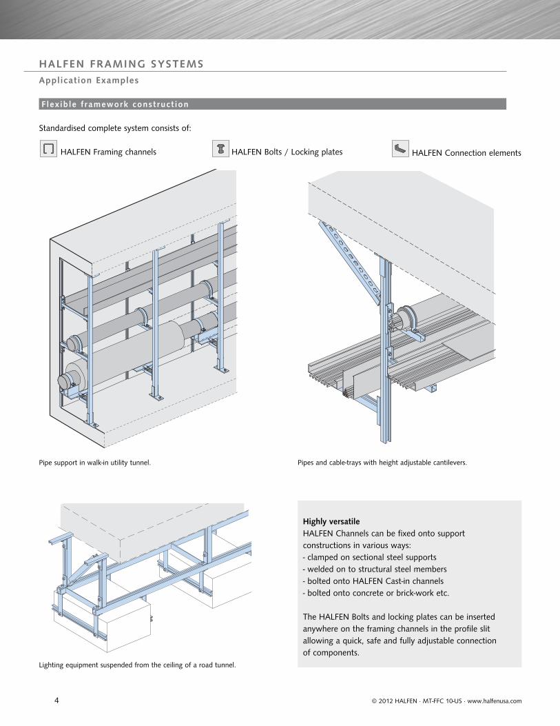
Standardised complete system consists of:
HALFEN Framing channels HALFEN Bolts / Locking plates
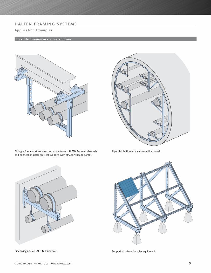
Pipe support in walk-in utility tunnel. Pipes and cable-trays with height adjustable cantilevers.
Lighting equipment suspended from the ceiling of a road tunnel.
HALFEN Connection elements
F lex ib le f ramework const ruct ion
Highly versatile HALFEN Channels can be fixed onto support constructions in various ways:- clamped on sectional steel supports- welded on to structural steel members- bolted onto HALFEN Cast-in channels- bolted onto concrete or brick-work etc.
The HALFEN Bolts and locking plates can be inserted anywhere on the framing channels in the profile slit allowing a quick, safe and fully adjustable connection of components.
5© 2012 HALFEN · MT-FFC 10-US · www.halfenusa.com
HALFEN FRAMING SYSTEMSApplication Examples
Pipe distribution in a walk-in utility tunnel.Fitting a framework construction made from HALFEN Framing channels and connection parts on steel supports with HALFEN Beam clamps.
Support structure for solar equipment. Pipe fixings on a HALFEN Cantilever.
F lex ib le f ramework const ruct ion
6
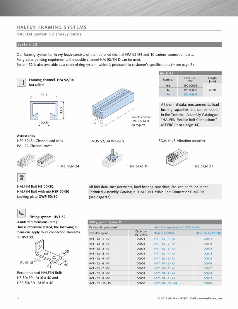
HM 52/34
Material Order no.0280.
Length[mm]
wb 190-00002
6070fv 190-00003
A4 190-00001
Fitting system System 52
FV - hot dip galvanized A4 = Stainless steel W1.4571/1.4401
Item description Order no.0312.040- Item description Order no. 0312.040-
HVT - 52 - 1 - FV 00001 HVT - 52 - 1 - A4 00011
HVT - 52 - 2 - FV 00002 HVT - 52 - 2 - A4 00012
HVT - 52 - 3 - FV 00003 HVT - 52 - 3 - A4 00013
HVT - 52 - 4 - FV 00004 HVT - 52 - 4 - A4 00014
HVT - 52 - 5 - FV 00005 HVT - 52 - 5 - A4 00015
HVT - 52 - 6 - FV 00006 HVT - 52 - 6 - A4 00016
HVT - 52 - 7 - FV 00007 HVT - 52 - 7 - A4 00017
HVT - 52 - 8 - FV 00008 HVT - 52 - 8 - A4 00018
HVT - 52 - 9 - FV 00009 HVT - 52 - 9 - A4 00019
HVT - 52 - 10 - FV 00010 HVT - 52 - 10 - A4 00020
52.5
22.5
33.5
25
8 50RL Ø 18
© 2012 HALFEN · MT-FFC 10-US · www.halfenusa.com
HALFEN FRAMING SYSTEMSHALFEN System 52 (heavy duty)
→ see page 24
HPE 52/34 Channel end caps PA - 22 Channel cover
double channel HM 52/34 D on request
System 52
All channel data, measurements, load bearing capacities, etc. can be found in the Technical Assembly Catalogue “HALFEN Flexible Bolt Connections” MT-FBC (→ see page 14)
All bolt data, measurements, load bearing capacities, etc. can be found in the Technical Assembly Catalogue “HALFEN Flexible Bolt Connections” MT-FBC (see page 17)
Accessories
VUS 52/34 Washers SDM 41/8 Vibration absorber
Our framing system for heavy loads consists of the hot-rolled channel HM 52/34 and 10 various connection parts. For greater bending requirements the double channel HM 52/34 D can be used. System 52 is also available as a channel ring system, which is produced to customer’s specifications (→ see page 8).
→ see page 19 → see page 23
Framing channel HM 52/34
HALFEN Bolt HS 50/30, HALFEN Bolt with nib HSR 50/30 Locking plate GWP 50/30
Fitting system HVT 52Standard dimensions [mm]:Unless otherwise stated, the following di-mensions apply to all connection elements for HVT 52.
Recommended HALFEN Bolts:HS 50/30 - M16 x 40 and HSR 50/30 - M16 x 40
hot-rolled
7
147
190
60
120
50
10060
1905
172
54
180180
5
135
25
60
125
75
5
75
180135
5
4
200
2005
230
60
805
HVT 52 - 8
© 2012 HALFEN · MT-FFC 10-US · www.halfenusa.com
HALFEN FRAMING SYSTEMSHALFEN System 52 (heavy duty)
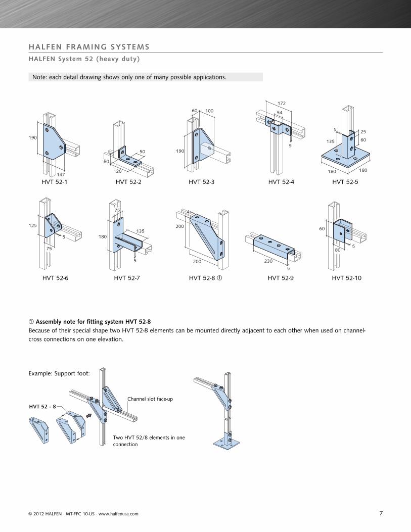
Note: each detail drawing shows only one of many possible applications.
HVT 52-1
HVT 52-6
HVT 52-2
HVT 52-7
HVT 52-3
HVT 52-8
HVT 52-4 HVT 52-5
HVT 52-9 HVT 52-10
Assembly note for fitting system HVT 52-8
Two HVT 52/8 elements in one connection
Channel slot face-up
Because of their special shape two HVT 52-8 elements can be mounted directly adjacent to each other when used on channel-cross connections on one elevation.
Example: Support foot:
8
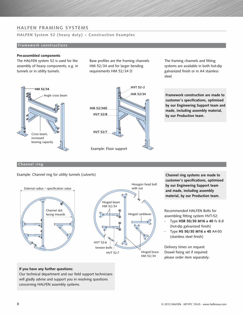
HM 52/34
HVT 52-2
HM 52/34D
HVT 52/8
HVT 52/7
Channel slot facing inwards
External radius = specification value
Hinged cantilever
Hinged beam HM 52/34
Hexagon head bolt with nut
tension boltsHinged braceHM 52/34
HVT 52-7
HVT 52-6
Angle cross beam
HM 52/34
Cross beam, increased bearing capacity
© 2012 HALFEN · MT-FFC 10-US · www.halfenusa.com
HALFEN FRAMING SYSTEMSHALFEN System 52 (heavy duty) – Construction Examples
Pre-assembled components
Example: Channel ring for utility tunnels (culverts)
Delivery times on request. Dowel fixing set if required: please order item separately.
Framework const ruct ions
Channel r ing
If you have any further questions: Our technical department and our field support technicians will gladly advise and support you in resolving questions concerning HALFEN assembly systems.
Example: Floor support
The HALFEN system 52 is used for the assembly of heavy components, e.g. in tunnels or in utility tunnels.
Base profiles are the framing channels HM 52/34 and for larger bending requirements HM 52/34 D
The framing channels and fitting systems are available in both hot-dip galvanized finish or in A4 stainless steel.
Recommended HALFEN Bolts for assembling fitting system HVT-52: - Type HSR 50/30 M16 x 40 fv 8.8 (hot-dip galvanized finish)- Type HS 50/30 M16 x 40 A4-50 (stainless steel finish)
Framework construction are made to customer’s specifications, optimised by our Engineering Support team and made, including assembly material, by our Production team.
Channel ring systems are made to customer’s specifications, optimised by our Engineering Support team and made, including assembly material, by our Production team.
9
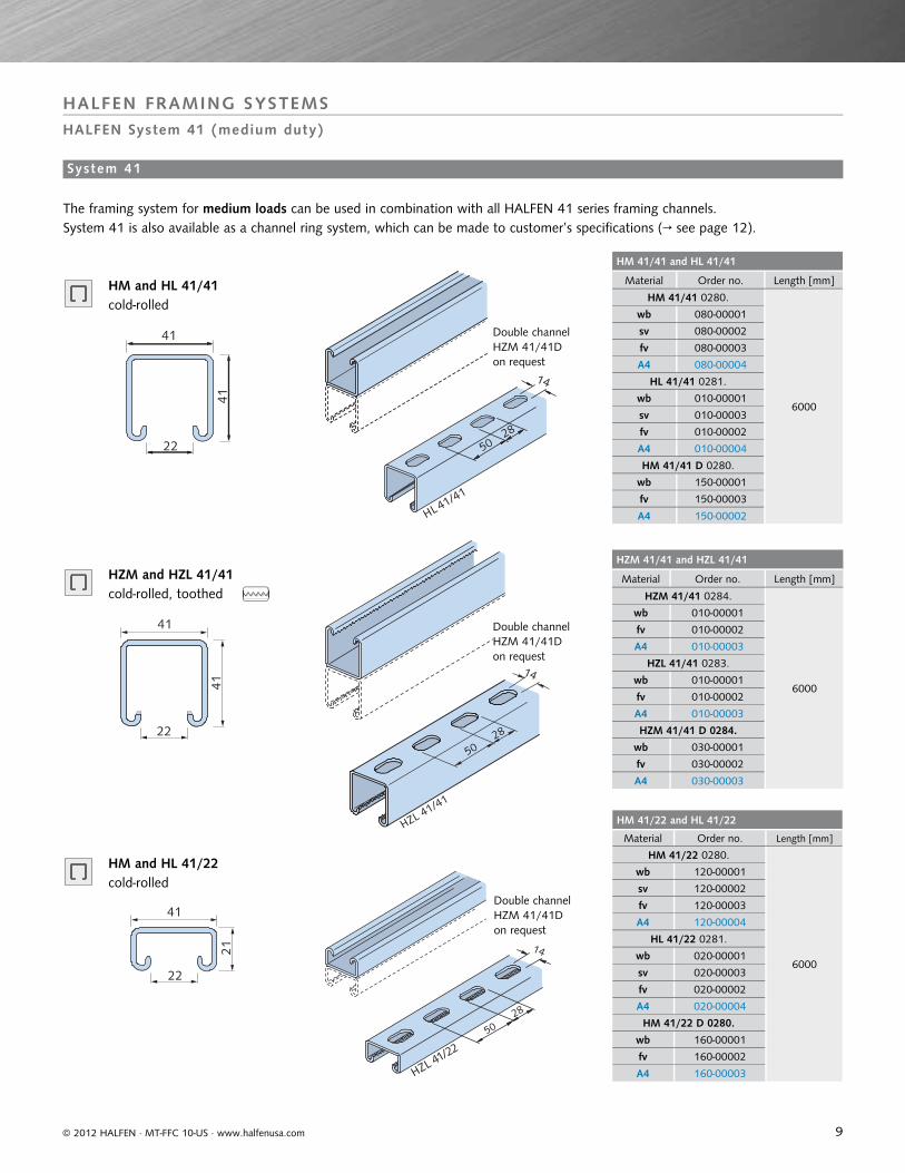
HM 41/41 and HL 41/41
Material Order no. Length [mm]
HM 41/41 0280.
6000
wb 080-00001
sv 080-00002
fv 080-00003
A4 080-00004
HL 41/41 0281.
wb 010-00001
sv 010-00003
fv 010-00002
A4 010-00004
HM 41/41 D 0280.
wb 150-00001
fv 150-00003
A4 150-00002
HZM 41/41 and HZL 41/41
Material Order no. Length [mm]
HZM 41/41 0284.
6000
wb 010-00001
fv 010-00002
A4 010-00003
HZL 41/41 0283.
wb 010-00001
fv 010-00002
A4 010-00003
HZM 41/41 D 0284.
wb 030-00001
fv 030-00002
A4 030-00003
HM 41/22 and HL 41/22
Material Order no. Length [mm]
HM 41/22 0280.
6000
wb 120-00001
sv 120-00002
fv 120-00003
A4 120-00004
HL 41/22 0281.
wb 020-00001
sv 020-00003
fv 020-00002
A4 020-00004
HM 41/22 D 0280.
wb 160-00001
fv 160-00002
A4 160-00003
HL 41/41
14
2850
41
41
22
41
41
22
41
21
22
14
28
50
HZL 41/22
© 2012 HALFEN · MT-FFC 10-US · www.halfenusa.com
HALFEN FRAMING SYSTEMSHALFEN System 41 (medium duty)
HM and HL 41/41 cold-rolled
Double channel HZM 41/41Don request
Double channel HZM 41/41Don request
Double channel HZM 41/41Don request
HZM and HZL 41/41 cold-rolled, toothed
System 41
The framing system for medium loads can be used in combination with all HALFEN 41 series framing channels.System 41 is also available as a channel ring system, which can be made to customer’s specifications (→ see page 12).
HM and HL 41/22 cold-rolled
HZL 41/41
14
28
50
10
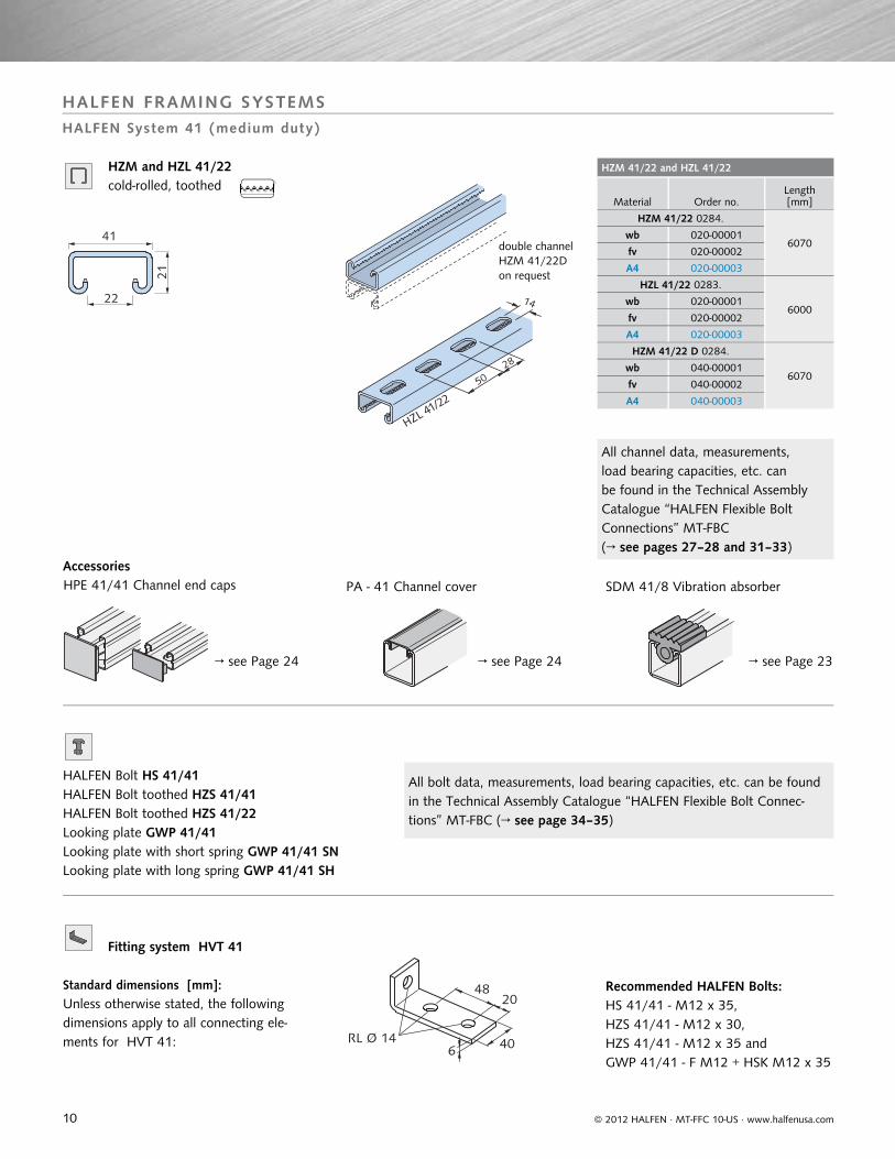
HZM 41/22 and HZL 41/22
Material Order no.Length[mm]
HZM 41/22 0284.
6070wb 020-00001
fv 020-00002
A4 020-00003
HZL 41/22 0283.
6000wb 020-00001
fv 020-00002
A4 020-00003
HZM 41/22 D 0284.
6070wb 040-00001
fv 040-00002
A4 040-00003
41
21
22 14
28
50
HZL 41/22
© 2012 HALFEN · MT-FFC 10-US · www.halfenusa.com
HALFEN FRAMING SYSTEMSHALFEN System 41 (medium duty)
HZM and HZL 41/22 cold-rolled, toothed
→ see Page 24 → see Page 24 → see Page 23
HPE 41/41 Channel end caps PA - 41 Channel cover SDM 41/8 Vibration absorber
HALFEN Bolt HS 41/41 HALFEN Bolt toothed HZS 41/41HALFEN Bolt toothed HZS 41/22Looking plate GWP 41/41Looking plate with short spring GWP 41/41 SNLooking plate with long spring GWP 41/41 SH
Accessories
All channel data, measurements, load bearing capacities, etc. can be found in the Technical Assembly Catalogue “HALFEN Flexible Bolt Connections” MT-FBC (→ see pages 27–28 and 31–33)
All bolt data, measurements, load bearing capacities, etc. can be found in the Technical Assembly Catalogue “HALFEN Flexible Bolt Connec-tions” MT-FBC (→ see page 34–35)
double channel HZM 41/22D on request
Fitting system HVT 41
4820
406RL Ø 14
Standard dimensions [mm]:Unless otherwise stated, the following dimensions apply to all connecting ele-ments for HVT 41:
Recommended HALFEN Bolts:HS 41/41 - M12 x 35, HZS 41/41 - M12 x 30,HZS 41/41 - M12 x 35 andGWP 41/41 - F M12 + HSK M12 x 35
11
79 60°
64 42
90
90
77
64
45°136
90
58 76 45°
232
164 50 50
89
104
41
104
47 98
137
42
90
138
138
51 21
41 54
41
50
50 50
50
47
178
96 96
47
47 43
83
41
54
41
137 38
47
98
137
41
47 41
21 100
ø 14
100
4060
812
0
140
4
135
65
8
120 206040
2 x ø 14
LL 13x26
88 136
184 41
57 40
100
5
200
197
200 184
5
115
50
4
70
102
102
60°48
86
© 2012 HALFEN · MT-FFC 10-US · www.halfenusa.com
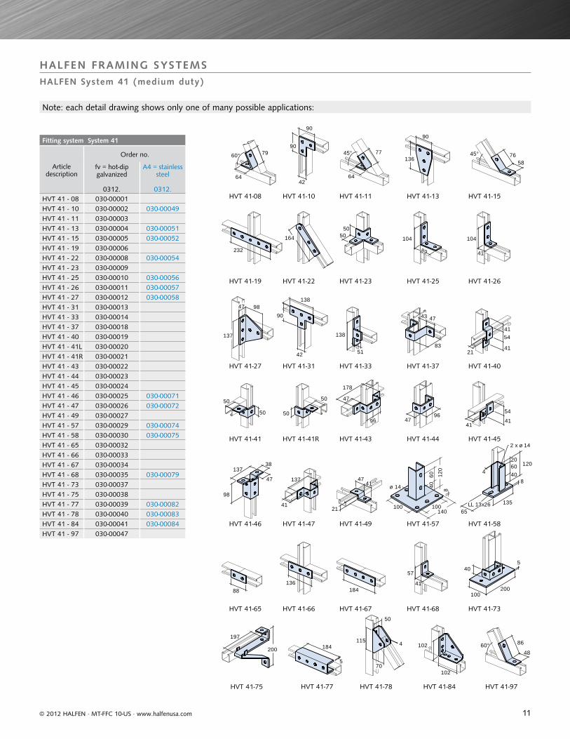
HALFEN FRAMING SYSTEMSHALFEN System 41 (medium duty)
Note: each detail drawing shows only one of many possible applications:
Fitting system System 41
Articledescription
Order no.
fv = hot-dip galvanized
0312.
A4 = stainless steel
0312.HVT 41 - 08 030-00001 HVT 41 - 10 030-00002 030-00049HVT 41 - 11 030-00003 HVT 41 - 13 030-00004 030-00051HVT 41 - 15 030-00005 030-00052HVT 41 - 19 030-00006 HVT 41 - 22 030-00008 030-00054HVT 41 - 23 030-00009 HVT 41 - 25 030-00010 030-00056 HVT 41 - 26 030-00011 030-00057HVT 41 - 27 030-00012 030-00058HVT 41 - 31 030-00013 HVT 41 - 33 030-00014 HVT 41 - 37 030-00018 HVT 41 - 40 030-00019 HVT 41 - 41L 030-00020 HVT 41 - 41R 030-00021 HVT 41 - 43 030-00022 HVT 41 - 44 030-00023 HVT 41 - 45 030-00024 HVT 41 - 46 030-00025 030-00071HVT 41 - 47 030-00026 030-00072HVT 41 - 49 030-00027 HVT 41 - 57 030-00029 030-00074HVT 41 - 58 030-00030 030-00075HVT 41 - 65 030-00032 HVT 41 - 66 030-00033 HVT 41 - 67 030-00034 HVT 41 - 68 030-00035 030-00079HVT 41 - 73 030-00037 HVT 41 - 75 030-00038 HVT 41 - 77 030-00039 030-00082HVT 41 - 78 030-00040 030-00083HVT 41 - 84 030-00041 030-00084HVT 41 - 97 030-00047
HVT 41-08
HVT 41-19
HVT 41-27 HVT 41-37
HVT 41-45
HVT 41-58
HVT 41-75
HVT 41-10
HVT 41-22
HVT 41-31 HVT 41-40
HVT 41-46
HVT 41-65
HVT 41-77
HVT 41-11
HVT 41-23
HVT 41-33
HVT 41-41
HVT 41-47
HVT 41-66
HVT 41-78
HVT 41-13
HVT 41-25
HVT 41-41R
HVT 41-49
HVT 41-67
HVT 41-84
HVT 41-15
HVT 41-26
HVT 41-43
HVT 41-57
HVT 41-68
HVT 41-97
HVT 41-73
HVT 41-44
12
Decription and order-no.
Material: fv = hot-dip galvanized Order no. 0304.
HCS - 41 - SRI - P - fv Radius Ra 010-00002
HCS - 41 - SRI - M - fv 020-00002
Material: A4 = Stainless steel
HCS - 41 - SRI - P - A4 Radius Ra 010-00001
HCS - 41 - SRI - M - A4 020-00002
Always specify external radius Ra [mm] when ordering
R a
Channel slot
Locking rod
Hexagon bolt and nut
Exter
nal r
adius
=
spec
ificati
on m
easu
remen
t
© 2012 HALFEN · MT-FFC 10-US · www.halfenusa.com
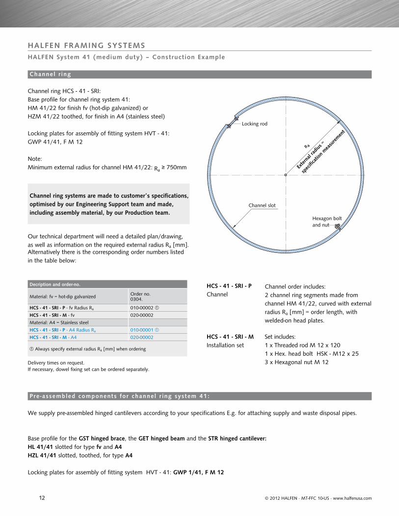
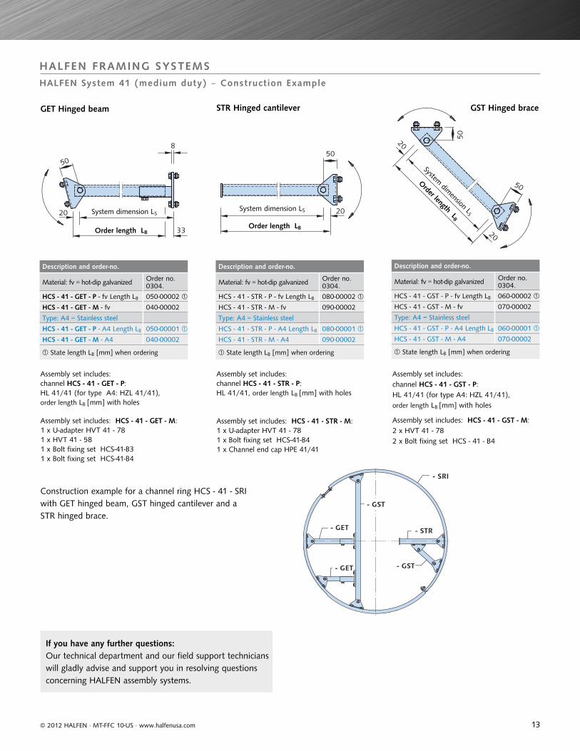
HALFEN FRAMING SYSTEMSHALFEN System 41 (medium duty) ‒ Construction Example
Channel order includes:2 channel ring segments made from channel HM 41/22, curved with external radius Ra [mm] = order length, with welded-on head plates.
HCS - 41 - SRI - PChannel
HCS - 41 - SRI - MInstallation set
Set includes:1 x Threaded rod M 12 x 1201 x Hex. head bolt HSK - M12 x 253 x Hexagonal nut M 12
Note: Minimum external radius for channel HM 41/22: Ra ≥ 750mm
Our technical department will need a detailed plan/drawing, as well as information on the required external radius Ra [mm].Alternatively there is the corresponding order numbers listed in the table below:
Channel ring HCS - 41 - SRI:Base profile for channel ring system 41:HM 41/22 for finish fv (hot-dip galvanized) orHZM 41/22 toothed, for finish in A4 (stainless steel)
Locking plates for assembly of fitting system HVT - 41:GWP 41/41, F M 12
Locking plates for assembly of fitting system HVT - 41: GWP 1/41, F M 12
Channel r ing
HL 41/41 slotted for type fv and A4HZL 41/41 slotted, toothed, for type A4
Pre -assembled components for channel r ing system 41:
Channel ring systems are made to customer’s specifications, optimised by our Engineering Support team and made, including assembly material, by our Production team.
Delivery times on request.If necessary, dowel fixing set can be ordered separately.
Base profile for the GST hinged brace, the GET hinged beam and the STR hinged cantilever:
We supply pre-assembled hinged cantilevers according to your specifications E.g. for attaching supply and waste disposal pipes.
13
Description and order-no.
Material: fv = hot-dip galvanized Order no.0304.
HCS - 41 - GST - P - fv Length LB 060-00002
HCS - 41 - GST - M - fv 070-00002
Type: A4 = Stainless steel
HCS - 41 - GST - P - A4 Length LB 060-00001
HCS - 41 - GST - M - A4 070-00002
State length LB [mm] when ordering
Description and order-no.
Material: fv = hot-dip galvanized Order no.0304.
HCS - 41 - GET - P - fv Length LB 050-00002
HCS - 41 - GET - M - fv 040-00002
Type: A4 = Stainless steel
HCS - 41 - GET - P - A4 Length LB 050-00001
HCS - 41 - GET - M - A4 040-00002
State length LB [mm] when ordering
Description and order-no.
Material: fv = hot-dip galvanized Order no.0304.
HCS - 41 - STR - P - fv Length LB 080-00002
HCS - 41 - STR - M - fv 090-00002
Type: A4 = Stainless steel
HCS - 41 - STR - P - A4 Length LB 080-00001
HCS - 41 - STR - M - A4 090-00002
State length LB [mm] when ordering
- SRI
- STR
- GST
- GST
- GET
- GET
8
20
33
5050
20System dimension LS
Order length LB20
50
5020
System dimension LS
Order length LB
System dimension LS
Order length LB
© 2012 HALFEN · MT-FFC 10-US · www.halfenusa.com
HALFEN FRAMING SYSTEMSHALFEN System 41 (medium duty) ‒ Construction Example
Assembly set includes: channel HCS - 41 - GST - P: HL 41/41 (for type A4: HZL 41/41), order length LB [mm] with holes
Assembly set includes: channel HCS - 41 - GET - P:HL 41/41 (for type A4: HZL 41/41), order length LB [mm] with holes
Assembly set includes: channel HCS - 41 - STR - P: HL 41/41, order length LB [mm] with holes
Assembly set includes: HCS - 41 - GET - M:1 x U-adapter HVT 41 - 781 x HVT 41 - 581 x Bolt fixing set HCS-41-B31 x Bolt fixing set HCS-41-B4
Assembly set includes: HCS - 41 - STR - M:1 x U-adapter HVT 41 - 781 x Bolt fixing set HCS-41-B41 x Channel end cap HPE 41/41
Assembly set includes: HCS - 41 - GST - M:2 x HVT 41 - 782 x Bolt fixing set HCS - 41 - B4
GST Hinged braceSTR Hinged cantileverGET Hinged beam
If you have any further questions: Our technical department and our field support technicians will gladly advise and support you in resolving questions concerning HALFEN assembly systems.
Construction example for a channel ring HCS - 41 - SRI with GET hinged beam, GST hinged cantilever and a STR hinged brace.
14
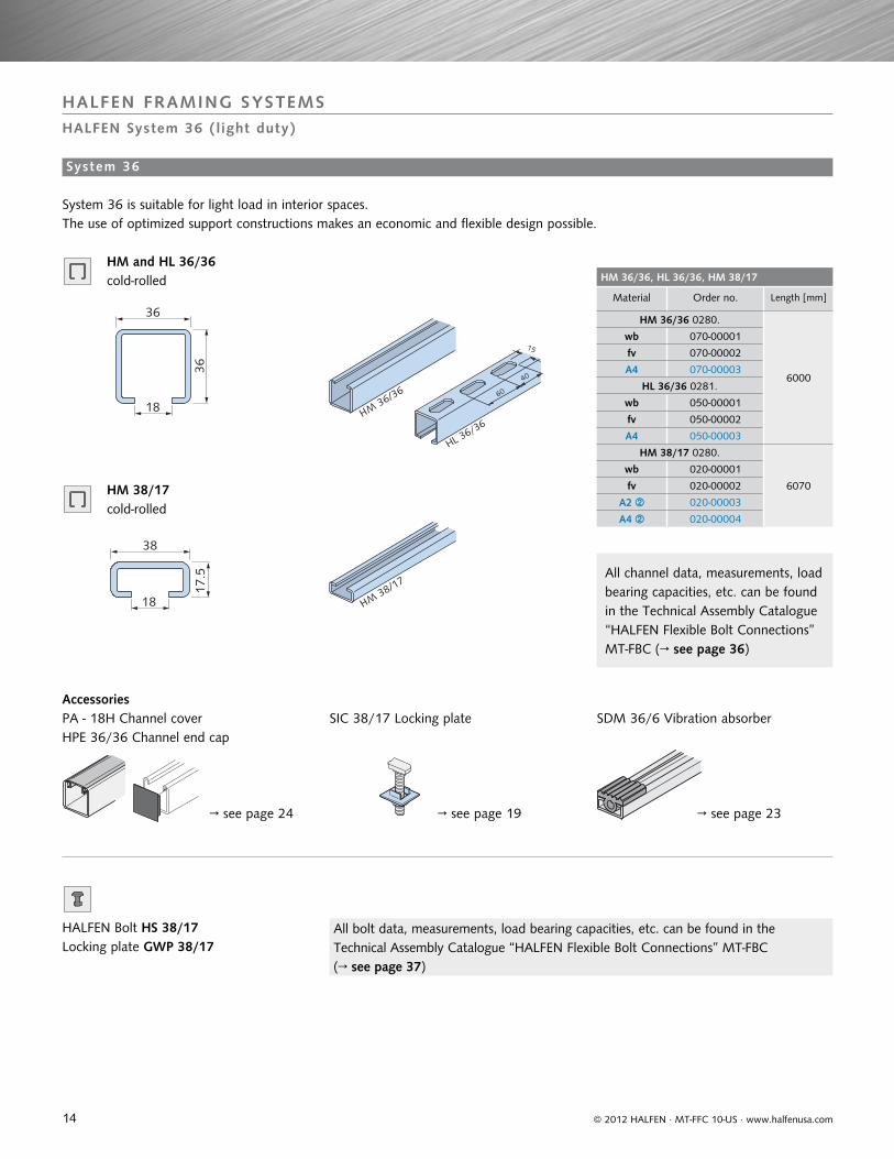
HM 36/36, HL 36/36, HM 38/17
Material Order no. Length [mm]
HM 36/36 0280.
6000
wb 070-00001
fv 070-00002
A4 070-00003
HL 36/36 0281.
wb 050-00001
fv 050-00002
A4 050-00003
HM 38/17 0280.
6070
wb 020-00001
fv 020-00002
A2 020-00003
A4 020-00004
36
36
18 HM36/36
40
60
15
HL 36/36
38
17.5
18 HM38/17
© 2012 HALFEN · MT-FFC 10-US · www.halfenusa.com
HALFEN FRAMING SYSTEMS
HALFEN System 36 (light duty)
SIC 38/17 Locking plate SDM 36/6 Vibration absorber
→ see page 23→ see page 19→ see page 24
HPE 36/36 Channel end cap PA - 18H Channel cover
HALFEN Bolt HS 38/17Locking plate GWP 38/17
HM and HL 36/36 cold-rolled
HM 38/17 cold-rolled
System 36
System 36 is suitable for light load in interior spaces. The use of optimized support constructions makes an economic and flexible design possible.
Accessories
All channel data, measurements, load bearing capacities, etc. can be found in the Technical Assembly Catalogue “HALFEN Flexible Bolt Connections” MT-FBC (→ see page 36)
All bolt data, measurements, load bearing capacities, etc. can be found in the Technical Assembly Catalogue “HALFEN Flexible Bolt Connections” MT-FBC (→ see page 37)
15
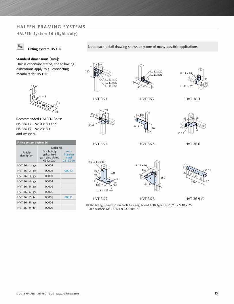
Fitting system System 36
Article-description
Order-no.fv = hot-dip galvanized
gv = zinc plated 0312.020-
A4 = Stainless
steel0312.020-
HVT 36 - 1 - gv 00001
HVT 36 - 2 - gv 00002 00010
HVT 36 - 3 - gv 00003
HVT 36 - 4 - gv 00004
HVT 36 - 5 - gv 00005
HVT 36 - 6 - gv 00006
HVT 36 - 7 - fv 00007 00011
HVT 36 - 8 - gv 00008
HVT 36 - 9 - fv 00009
5
11
33
r = 3
110
110
LL 11 x 30LL 11 x 25LL 11 x 50
LL 11 x 20
80
LL 11 x 25
36
LL 11 x 20
LL 11 x 2536
36
36
354
Ø 11
37103
130
Ø 1180
4
363545
Ø 11
1004025
LL 13 x 26
6
65
2 x LL 11 x 30
135
150
LL 13 x 26
Ø 13
150
4
Ø 1120
22060
20
6060
© 2012 HALFEN · MT-FFC 10-US · www.halfenusa.com
HALFEN FRAMING SYSTEMS
HALFEN System 36 (light duty)
Fitting system HVT 36
Standard dimensions [mm]:Unless otherwise stated, the following dimensions apply to all connecting members for HVT 36:
Recommended HALFEN Bolts:HS 38/17 - M10 x 30 andHS 38/17 - M12 x 30and washers.
HVT 36-1
HVT 36-4
HVT 36-7
HVT 36-2
HVT 36-5
HVT 36-8
HVT 36-3
HVT 36-6
HVT 36-9
The fitting is fixed to channels by using T-head bolts type HS 28/15 - M10 x 25 and washers M10 DIN EN ISO 7093-1.
Note: each detail drawing shows only one of many possible applications.
16
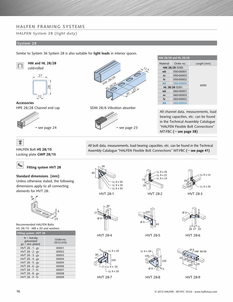
HM 28/28 and HL 28/28
Material Order no. Length [mm]
HM 28/28 0280.
6000
wb 050-00001sv 050-00003fv 050-00002A4 050-00004HL 28/28 0281.
wb 060-00001sv 060-00003fv 060-00002A4 060-00004
Fitting system HVT 28
fv = hot-dip galvanized
gv = zinc plated.
Order-no.0312.010-
HVT 28 - 1 - gv 00001HVT 28 - 2 - gv 00002HVT 28 - 3 - gv 00003HVT 28 - 4 - gv 00004HVT 28 - 5 - gv 00005HVT 28 - 6 - gv 00006HVT 28 - 7 - fv 00007HVT 28 - 8 - gv 00008HVT 28 - 9 - fv 00009
28
12
27
HM28/28
12,5
25
40
HL 28/28
4
9
25
90
90
LL 9 x 26LL 9 x 30
LL 9 x 30
LL 9 x 26
70
LL 9 x 22LL 9 x 14
28
282835
LL 9 x 14
LL 9 x 26
3
Ø 9
27
80
29103
63Ø 9
3Ø 9
2728 33
LL 9 x 18
5
80
LL 9 x 18
100
2 x LL 9 x 26
LL 9 x 18
100
3Ø 9
100
Ø 9
20
HM 36/36
40160 20
4040
© 2012 HALFEN · MT-FFC 10-US · www.halfenusa.com
System 28
HALFEN FRAMING SYSTEMS
HALFEN System 28 (light duty)
HM and HL 28/28 cold-rolled
Similar to System 36 System 28 is also suitable for light loads in interior spaces.
SDM 28/6 Vibration absorberHPE 28/28 Channel end capAccessories
All channel data, measurements, load bearing capacities, etc. can be found in the Technical Assembly Catalogue “HALFEN Flexible Bolt Connections” MT-FBC (→ see page 38)
→ see page 23 → see page 24
HALFEN Bolt HS 28/15Locking plate GWP 28/15
All bolt data, measurements, load bearing capacities, etc. can be found in the Technical Assembly Catalogue “HALFEN Flexible Bolt Connections” MT-FBC (→ see page 41)
Fitting system HVT 28
Standard dimensions [mm]:Unless otherwise stated, the following dimensions apply to all connecting elements for HVT 28:
Recommended HALFEN Bolts:HS 28/15 - M8 x 20 and washers.
HVT 28-1
HVT 28-4
HVT 28-7
HVT 28-2
HVT 28-5
HVT 28-8
HVT 28-3
HVT 28-6
HVT 28-9
17
HL 36/36
HVT 36-2
HVT 36-7
HVT 36-7HL 36/36
HVT 28 - 7HL 28/28
HL 28/28
HVT 28 - 7
HL 28/28
HVT 28 - 2
© 2012 HALFEN · MT-FFC 10-US · www.halfenusa.com
HALFEN FRAMING SYSTEMS
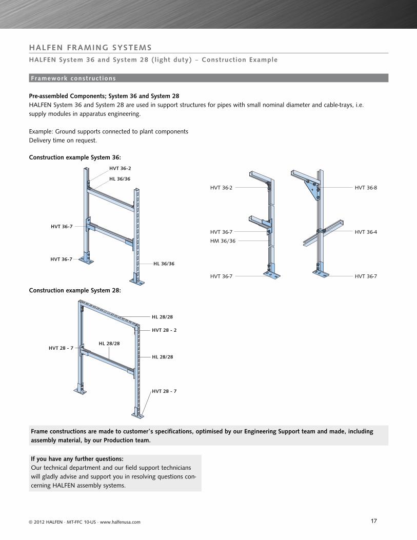
HALFEN System 36 and System 28 (light duty) ‒ Construction Example
Framework const ruct ions
Pre-assembled Components; System 36 and System 28
Construction example System 36:
Construction example System 28:
Delivery time on request.
HVT 36-2 HVT 36-8
HVT 36-7
HVT 36-7 HVT 36-7
HVT 36-4
HM 36/36
Frame constructions are made to customer’s specifications, optimised by our Engineering Support team and made, including assembly material, by our Production team.
HALFEN System 36 and System 28 are used in support structures for pipes with small nominal diameter and cable-trays, i.e. supply modules in apparatus engineering.
Example: Ground supports connected to plant components
If you have any further questions: Our technical department and our field support technicians will gladly advise and support you in resolving questions con-cerning HALFEN assembly systems.
18
gv Strength grade 4.6
Thread
Stainless steel A4
Thread
Length Load capacity
[mm] [kN]
M 6 M 6 1000 2.2
M 8 M 8 1000 4.0
M 10 M 10 1000 6.4
M 12 M 12 1000 9.3
M 16 M 16 1000 17.3
M 20 M 20 1000 27
M 24 1000 38.8Order example: GWS - M 12 × 1000 - gv
gvStrength grade 8.8
Dimensions
Stainless steel A4
Dimensions
S S
DIN EN
[mm] [mm]
M 6 x 12 10
10 M 6 x 25
M 8 x 25 M 8 x 2513 13
M 8 x 40
M 10 x 20
17 16
M 10 x 30 M 10 x 30
M 10 x 45 M 10 x 45
M 10 x 60
M 10 x 70
M 12 x 22
19
18
M 12 x 25 M 12 x 25
M 12 x 30 M 12 x 30
M 12 x 40 M 12 x 40
M 12 x 50
M 12 x 60 M 12 x 60
M 12 x 80 M 12 x 80
M 12 x 90
M 16 x 40 M 16 x 40
24 24M 16 x 60 M 16 x 60
M 16 x 90 M 16 x 90
gv Strength grade 8Thread
Stainless steel A4
Thread
S/m S/m e
DIN ISO DIN
[mm] [mm] [mm]
M 6 M 6 10/5 10/6 11.5
M 8 M 8 13/6.5 13/7.5 15.0
M 10 M 10 17/8 16/9.5 19.6
M 12 M 12 19/10 18/12 21.9
M 16 M 16 24/13 24/15,5 27.7
M 20 M 20 30/16 30/19 34.6
M 24 M 24 36/19 36/22 41.5
fv
Thread
Stainless steel A2
Thread
S/m S/m e
DIN EN
[mm] [mm] [mm]
M6, M8 M 8 13/6,5 13/7.5 15.0
M 10 M 10 17/08 16/ 9.5 19.6
M 12 M 12 19/10 18/12 21.9
M 16 M 16 24/13 24/15.5 27.7
gv
for bolt
Stainless steel A4
for bolt
D d s
[mm] [mm] [mm]
M 6 M 6 12 6.4 1.6
M 8 M 8 16 8.4 1.6
M 10 M 10 21 10.5 2
M 12 M 12 24 13 2.5
M 16 M 16 30 17 3
M 20 M 20 37 21 3
M 24 M 24 44 25 4
fv
for bolt
Stainless steel A2
for bolt
D d s
[mm] [mm] [mm]
M 8 17 8.4 1.6
M 10 M 10 21 10.5 2
M 12 M 12 24 13 2.5
M 16 M 16 30 17 3
Order example: US - gv - M 12 - DIN 125
fv
Type
Stainless steel A4
Type
t w d F
[mm] [mm] [mm] [kN]
1 1 6 40 13 1.5
2 2 8 50 17 3.3
3 3 10 50 17 5
Reccomended. max. load
DINEN
gv
for bolt
Stainless steel A4
for bolt
D d s
[mm] [mm] [mm]
7094 M 6 22 6.6 2
7093-1 M 8 M 8 24 8.4 2
7093-1 M 10 M 10 30 10.5 2,5
7094 M 12 45 13.5 4
7093-1 M 12 M 12 37 13 3
7093-1 M 16 M 16 50 17 3
7094 M 20 72 22 6
Order example: US - M 12 - gv - DIN EN ISO 7093-1
Querschnitt
© 2012 HALFEN · MT-FFC 10-US · www.halfenusa.com
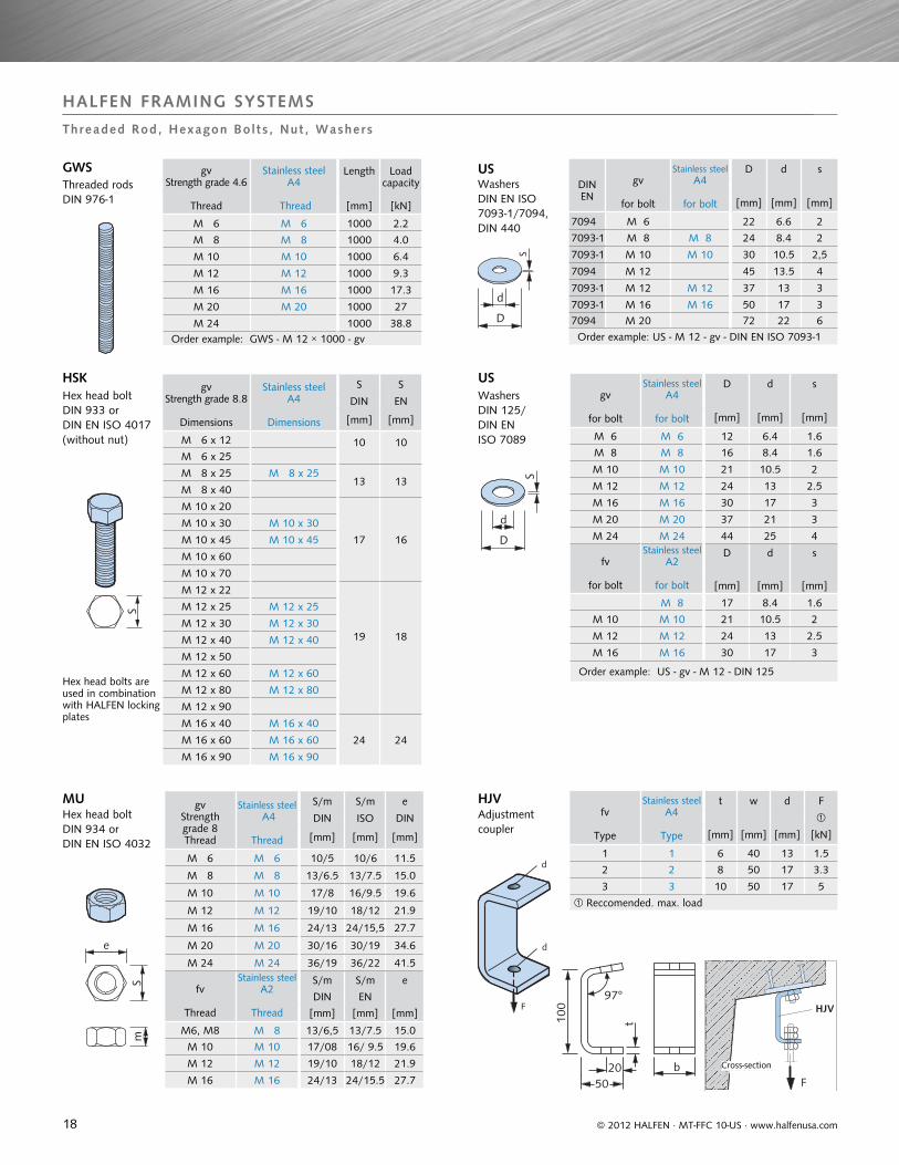
HALFEN FRAMING SYSTEMS
Threaded Rod, Hexagon Bol ts , Nut , Washers
GWSThreaded rodsDIN 976-1
HSKHex head boltDIN 933 or DIN EN ISO 4017(without nut)
MUHex head boltDIN 934 orDIN EN ISO 4032
Hex head bolts areused in combinationwith HALFEN locking plates
USWashersDIN 125/ DIN EN ISO 7089
HJVAdjustment coupler
WashersDIN EN ISO 7093-1/7094, DIN 440
US
Cross-section
19
gv C 15 EThread
d Load capacity
[mm]
[kN]
M 8 20 1.4
M 10 25 2.3
M 12 30 3.4
M 16 35 7.0
M 20 40 12.0
Recommended max. centre pull out in accordance with DIN 582
VUSSquare washers fv
for bolts
Stainless steel A4
for bolts
a x b x d
[mm]
VUS 40/25 for channel40/25;HZA 41/22
M 10 M 10 40 x 40 x 5
M 12 M 12 40 x 40 x 5
M 16 M 16 40 x 40 x 5
VUS 49/30 for channel 54/33,49/30
M 10 M 10 37 x 37 x 5
M 12 M 12 37 x 37 x 5
M 16 M 16 37 x 37 x 5
M 20 M 20 37 x 37 x 5
VUS 52/34 for channel52/34, 50/30
M 16 M 16 50 x 50 x 6
M 20 M 20 50 x 50 x 6
VUS 72/49 for channel72/48,72/49
M 20 M 20 54 x 54 x 6
M 24 M 24 54 x 54 x 6
M 27 M 27 54 x 54 x 6
M 30 M 30 54 x 54 x 6
VUS 41/41for all41er channels
M 6 M 6 40 x 40 x 6
M 10 M 10 40 x 40 x 6
M 12 M 12 40 x 40 x 6
Order example: VUS 52/34 - fv - M 20
gv
Thread
Stainless steel A4
Thread
D L Load capacity
[mm]
[mm]
[kN]
M 6 M 6 10/10 15 2.2
M 8 M 8 12/14 20 4.0
M 10 M 10 13/16 25 6.4
M 12 M 12 16/20 30 9.3
M 16 M 16 21/25 40 17.3
M 20 M 20 26/32 50 27.0
Recomm. max. working load with centre pull out Dimension D for type gv / A4
fv
Thread
Stainless steel A4
Thread
S L Load capacity.
[mm] [mm] [kN]
M 10 M 10 13 40 6.4
M 12 M 12 17 40 9.3
M 16 M 16 22 50 17.3
Recomm. max. working load with centre pull out Order example: SKM - fv - M 12
Stainless steel A4
Thread M 12× Length L [mm]
Stainless steel A4
Thread M 16× Length L [mm]
D D
forM12[mm]
forM16[mm]
M12 × 60 M16 × 60 16 22
M12 × 75 M16 × 75 16 22
M12 × 95 M16 × 95 16 22
M12 × 115 M16 × 115 16 22
M12 × 135 M16 × 135 16 22
perm. load: 5 kN perm. Load: 10 kN
Order example: SPH - A4 - M 12 x 75
gv
Article-description
Stainless steel
A4
Article-description
Fits T-head bolt
Type Dimensions
SIC - 50/30 - gv SIC - 50/30 - A4 50/30 M16, M20
SIC - 40/22 - gv SIC - 40/22 - A4 38/1740/22 M16
SIC - 38/23 - gv 38/23 M16
SIC - 29/20 - gv 29/20 M12
SIC - 38/17 - gv SIC - 38/17 - A4 38/1740/22 M12, M10
SIC - 28/15 - gv SIC - 28/15 - A4 28/15 M8, M10
SIC - 20/12 - gv SIC - 20/12 - A4 20/12 M8
Order example: SIC - 38/17- gv
© 2012 HALFEN · MT-FFC 10-US · www.halfenusa.com
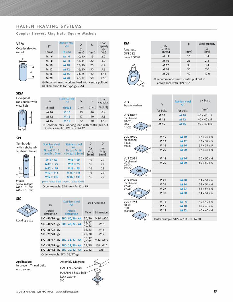
HALFEN FRAMING SYSTEMS
Coupler S leeves, R ing Nuts , Square Washers
VBMCoupler sleeves, round
SKMHexagonal rod-coupler with view hole
SPH
Turnbucklewith right-hand/left-hand thread
SIC
Locking plate
Application: to prevent T-head bolts unscrewing.
RM
Ring nutsDIN 582issue 2003-8
f= min. screw-in-depthM12 = 10 mmM16 = 13 mm
Assembly Diagram:
HALFEN Channel
HALFEN T-head boltLock washerSIC
20
Descriptionfv = hot-dip galvanized
A4 = stainless steelOrder no.
HVT 41 - 85 - fv 0312.030-00042
HVT 41 - 85 - A4 0312.030-00085
Descriptionfv = hot-dip galvanized
A4 = stainless steelOrder no.
HVT 41 - 86 - fv 0312.030-00044
HVT 41 - 86 - A4 0312.030-00086
Descriptionfv = hot-dip galvanized
A4 = stainless steelOrder no.
HVT 41 - 89 - fv 0312.030-00046
HVT 41 - 89 - A4 on request
U-clamp-plate KUS
Type fv = hot-dip galvanized
Order no.
KUS 0314.000-00001
Type A4 = stainless steel
Order-no.
KUS 0314.000-00002
Ø 13
40
15
50
4
6
22 75
86� 22
2275
127
6
22≤
1022
36
Beam clamps for 41 series; used in pairs
© 2012 HALFEN · MT-FFC 10-US · www.halfenusa.com
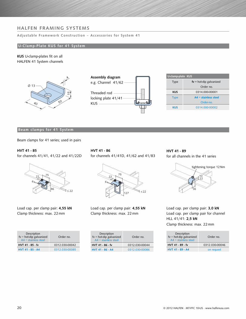
HALFEN FRAMING SYSTEMS
Adjustable Framework Construct ion ‒ Accessor ies for System 41
Load cap. per clamp pair: 4,55 kN
HVT 41 - 85 HVT 41 - 86 HVT 41 - 89
Clamp thickness: max. 22 mm
Clamp thickness: max. 22 mm
Load cap. per clamp pair: 4,55 kN Load cap. per clamp pair: 3,0 kNLoad cap. per clamp pair for channel HLL 41/41: 2,5 kN
for channels 41/41, 41/22 and 41/22D for channels 41/41D, 41/62 and 41/83 for all channels in the 41 series
Clamp thickness: max. 22 mm
tightening torque 12 Nm
Assembly diagram
KUS U-clamp-plates fit on all HALFEN 41 System channels
Threaded rod
e.g. Channel 41/62
locking plate 41/41KUS
Beam c lamps for 41 System
U-Clamp-P late KUS for 41 System
21
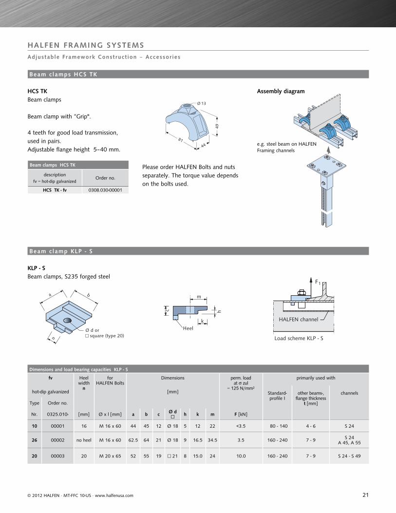
Beam clamps HCS TK
descriptionfv = hot-dip galvanized
Order no.
HCS TK - fv 0308.030-00001
Dimensions and load bearing capacities KLP - S
fv Heel width
n
for HALFEN Bolts
Dimensions perm. loadat zul
= 125 N/mm²
primarily used with
hot-dip galvanized [mm] Standard-profile I
other beams-,flange thickness
t [mm]
channels
Type Order no.
Nr. 0325.010- [mm] Ø x l [mm] a b c Ø d □ h k m F [kN]
10 00001 16 M 16 x 60 44 45 12 Ø 18 5 12 22 <3.5 80 - 140 4 - 6 S 24
26 00002 no heel M 16 x 60 62.5 64 21 Ø 18 9 16.5 34.5 3.5 160 - 240 7 - 9 S 24A 45, A 55
20 00003 20 M 20 x 65 52 55 19 □ 21 8 15.0 24 10.0 160 - 240 7 - 9 S 24 - S 49
44
49
81
Ø 13
b
n
a
Ø d or□ square (type 20)
c h
k
m
Heel
F1
Load scheme KLP - S
HALFEN channel
© 2012 HALFEN · MT-FFC 10-US · www.halfenusa.com
HALFEN FRAMING SYSTEMS
Adjustable Framework Construct ion ‒ Accessor ies
e.g. steel beam on HALFEN Framing channels
Please order HALFEN Bolts and nuts separately. The torque value depends on the bolts used.
HCS TK Beam clamps
Beam clamp with “Grip".
4 teeth for good load transmission, used in pairs.Adjustable flange height 5–40 mm.
Beam c lamps HCS TK
Assembly diagram
KLP - S Beam clamps, S235 forged steel
Beam c lamp KLP - S
22
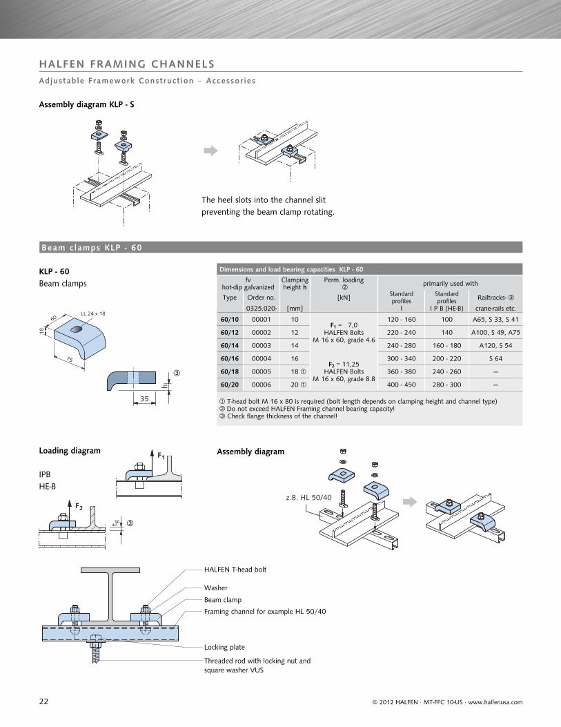
Dimensions and load bearing capacities KLP - 60
fv hot-dip galvanized
Clamping height h
Perm. loading primarily used with
Type Order no. [kN] Standard profiles
Standard profiles Railtracks-
0325.020- [mm] I I P B (HE-B) crane-rails etc.
60/10 00001 10F1 = 7,0
HALFEN BoltsM 16 x 60, grade 4.6
120 - 160 100 A65, S 33, S 41
60/12 00002 12 220 - 240 140 A100, S 49, A75
60/14 00003 14 240 - 280 160 - 180 A120, S 54
60/16 00004 16F2 = 11,25
HALFEN BoltsM 16 x 60, grade 8.8
300 - 340 200 - 220 S 64
60/18 00005 18 360 - 380 240 - 260 —
60/20 00006 20 400 - 450 280 - 300 —
T-head bolt M 16 x 80 is required (bolt length depends on clamping height and channel type)Do not exceed HALFEN Framing channel bearing capacity! Check flange thickness of the channel!
LL 24 x 18
75
18
60
h
35
F1
F2
t g
z.B. HL 50/40
© 2012 HALFEN · MT-FFC 10-US · www.halfenusa.com
HALFEN FRAMING CHANNELS
Adjustable Framework Construct ion ‒ Accessor ies
HALFEN T-head bolt
IPBHE-B
Washer
Beam clamp
Framing channel for example HL 50/40
Locking plate
Threaded rod with locking nut and square washer VUS
KLP - 60 Beam clamps
Beam c lamps KLP - 60
Loading diagram Assembly diagram
The heel slots into the channel slit preventing the beam clamp rotating.
Assembly diagram KLP - S
23
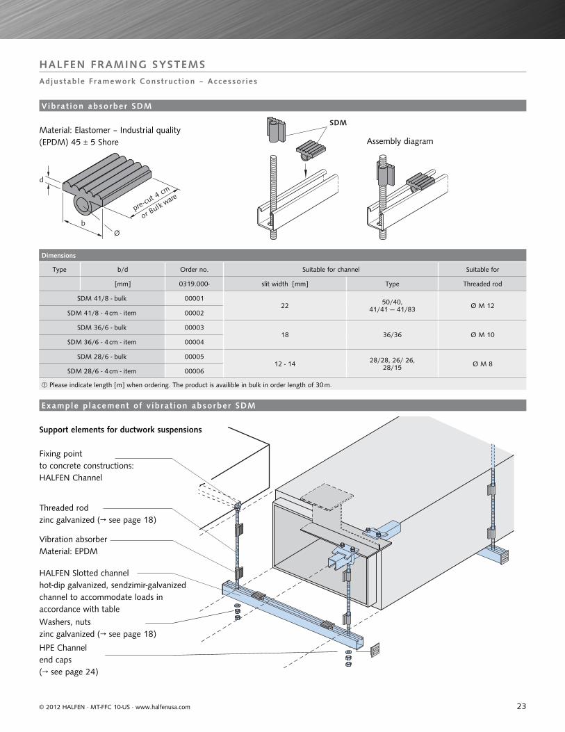
Dimensions
Type b/d Order no. Suitable for channel Suitable for
[mm] 0319.000- slit width [mm] Type Threaded rod
SDM 41/8 - bulk 0000122 50/40,
41/41 — 41/83 Ø M 12SDM 41/8 - 4 cm - item 00002
SDM 36/6 - bulk 0000318 36/36 Ø M 10
SDM 36/6 - 4 cm - item 00004
SDM 28/6 - bulk 0000512 - 14 28/28, 26/ 26,
28/15 Ø M 8SDM 28/6 - 4 cm - item 00006
Please indicate length [m] when ordering. The product is availible in bulk in order length of 30 m.
Øb
d
or Bulk ware
pre-cut 4
cm
SDM
© 2012 HALFEN · MT-FFC 10-US · www.halfenusa.com
HALFEN FRAMING SYSTEMS
Adjustable Framework Construct ion ‒ Accessor ies
Vibrat ion absorber SDM
Material: Elastomer – Industrial quality (EPDM) 45 ± 5 Shore Assembly diagram
Support elements for ductwork suspensions
Fixing pointto concrete constructions:HALFEN Channel
Threaded rodzinc galvanized (→ see page 18)
Vibration absorberMaterial: EPDM
HALFEN Slotted channelhot-dip galvanized, sendzimir-galvanized channel to accommodate loads in accordance with table
Washers, nuts zinc galvanized (→ see page 18)
HPE Channel end caps (→ see page 24)
Example p lacement of v ibrat ion absorber SDM
24
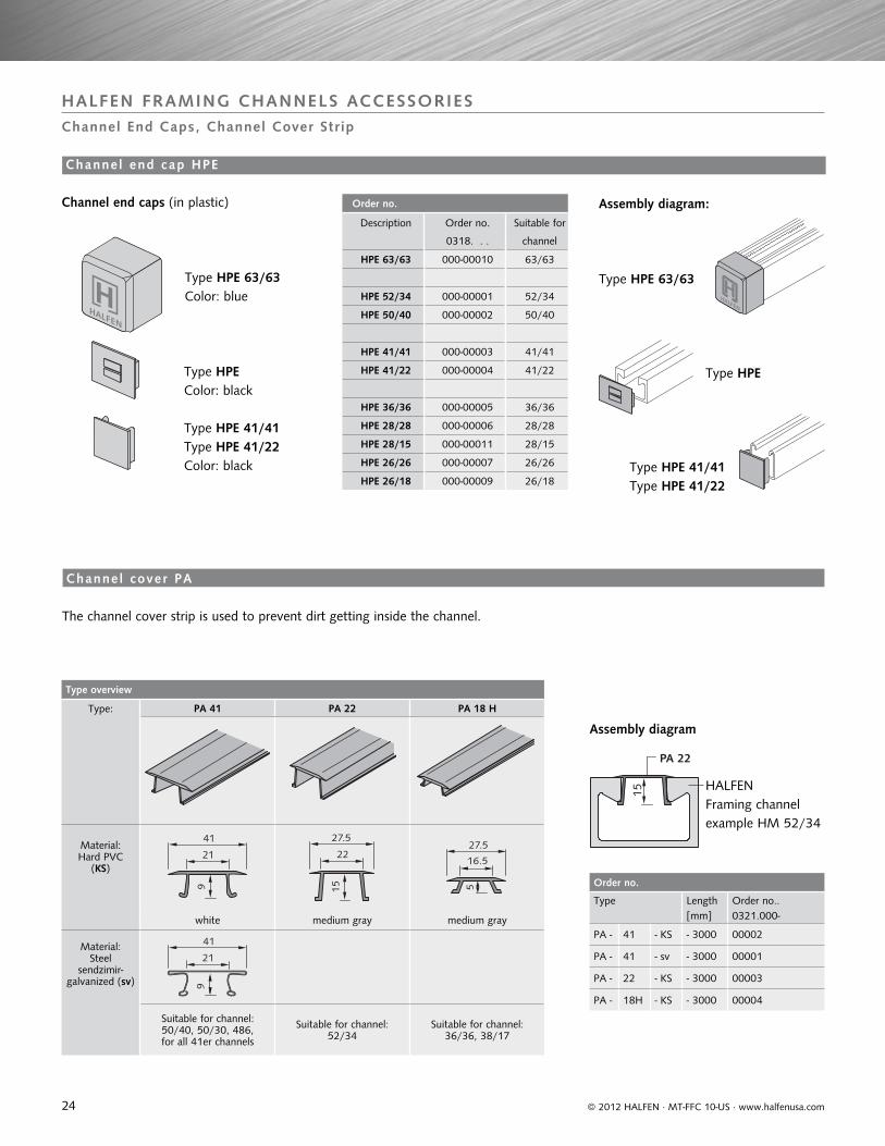
Order no.
Type Length Order no..[mm] 0321.000-
PA - 41 - KS - 3000 00002
PA - 41 - sv - 3000 00001
PA - 22 - KS - 3000 00003
PA - 18H - KS - 3000 00004
Type overview
Type: PA 41 PA 22 PA 18 H
Material:Hard PVC
(KS)
41
21
9
27.5
22
15
27.5
5
16.5
white medium gray medium gray
Material:Steel
sendzimir-galvanized (sv)
41
21
9
Suitable for channel:50/40, 50/30, 486, for all 41er channels
Suitable for channel:52/34
Suitable for channel:36/36, 38/17
Order no.
Description Order no. Suitable for
0318. . . channel
HPE 63/63 000-00010 63/63
HPE 52/34 000-00001 52/34
HPE 50/40 000-00002 50/40
HPE 41/41 000-00003 41/41
HPE 41/22 000-00004 41/22
HPE 36/36 000-00005 36/36
HPE 28/28 000-00006 28/28
HPE 28/15 000-00011 28/15
HPE 26/26 000-00007 26/26
HPE 26/18 000-00009 26/18
HALFENHALFEN
PA 22
15
© 2012 HALFEN · MT-FFC 10-US · www.halfenusa.com
HALFEN FRAMING CHANNELS ACCESSORIESChannel End Caps, Channel Cover Strip
Assembly diagram:Channel end caps (in plastic)
Type HPE 63/63Color: blue
Type HPEColor: black
Type HPE 41/41Type HPE 41/22Color: black
Type HPE 63/63
Type HPE
Type HPE 41/41Type HPE 41/22
HALFENFraming channel example HM 52/34
The channel cover strip is used to prevent dirt getting inside the channel.
Assembly diagram
Channel end cap HPE
Channel cover PA
25© 2012 HALFEN · MT-FFC 10-US · www.halfenusa.com
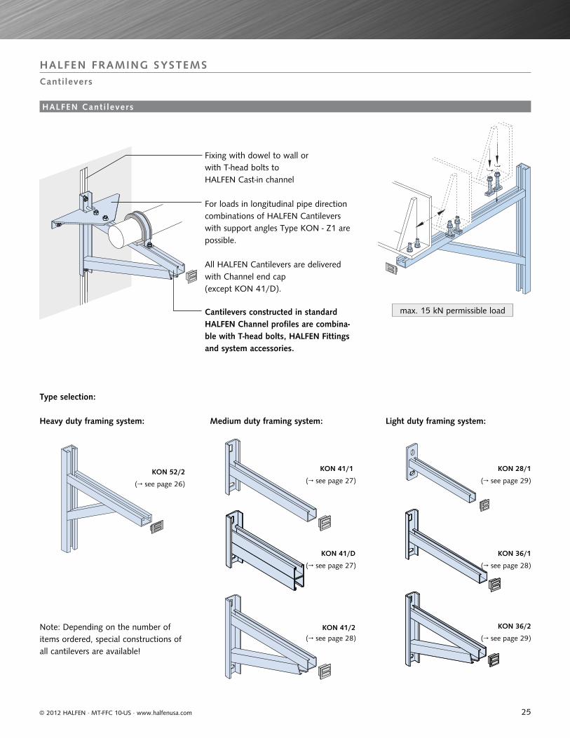
max. 15 kN permissible load
Fixing with dowel to wall or with T-head bolts to HALFEN Cast-in channel
For loads in longitudinal pipe direction combinations of HALFEN Cantilevers with support angles Type KON - Z1 are possible.
Cantilevers constructed in standard HALFEN Channel profiles are combina-ble with T-head bolts, HALFEN Fittings and system accessories.
All HALFEN Cantilevers are delivered with Channel end cap (except KON 41/D).
Heavy duty framing system:
Type selection:
Medium duty framing system: Light duty framing system:
Note: Depending on the number of items ordered, special constructions of all cantilevers are available!
KON 28/1
KON 36/1
KON 36/2
KON 41/1
KON 41/D
KON 41/2
KON 52/2
(→ see page 26) (→ see page 27) (→ see page 29)
(→ see page 28)(→ see page 27)
(→ see page 28) (→ see page 29)
HALFEN FRAMING SYSTEMS
Cantilevers
HALFEN Cant i levers
26
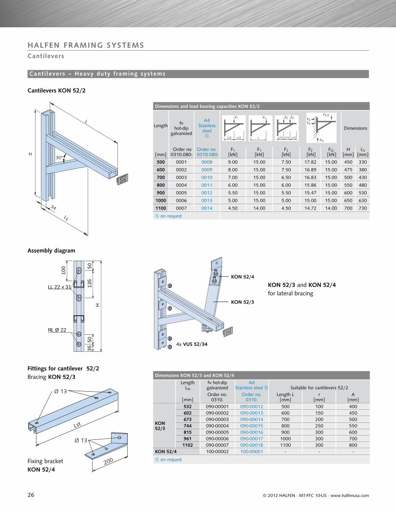
Dimensions and load bearing capacities KON 52/2
Length fv hot-dip
galvanized
A4 Stainless
steel
Dimensions
[mm] Order no 0310.080-
Order no. 0310.080-
F1 [kN]
F1 [kN]
F2 [kN]
FZ [kN]
FQ [kN]
H[mm]
LS[mm]
500 0001 0008 9.00 15.00 7.50 17.82 15.00 450 330
600 0002 0009 8.00 15.00 7.50 16.89 15.00 475 380
700 0003 0010 7.00 15.00 6.50 16.83 15.00 500 430
800 0004 0011 6.00 15.00 6.00 15.86 15.00 550 480
900 0005 0012 5.50 15.00 5.50 15.47 15.00 600 530
1000 0006 0013 5.00 15.00 5.00 15.00 15.00 650 630
1100 0007 0014 4.50 14.00 4.50 14.72 14.00 700 730
on request
Dimensions KON 52/3 and KON 52/4Length
LSt
fv hot-dip galvanized
A4 Stainless steel Suitable for cantilevers 52/2
[mm]Order no.
0310.Order no.
0310.Length L
[mm]r
[mm]A
[mm]
KON 52/3
532 090-00001 090-00012 500 100 400602 090-00002 090-00013 600 150 450673 090-00003 090-00014 700 200 500744 090-00004 090-00015 800 250 550815 090-00005 090-00016 900 300 600961 090-00006 090-00017 1000 300 7001102 090-00007 090-00018 1100 300 800
KON 52/4 100-00002 100-00001 - - -
on request
L/2L/2
1F
L/3L/3L/3
2F2F
L
1F1/2F
FZ
FQ
FZ
30°
LS
L
34
H
50
H
135
100
LL 22 x 31
5035
RL Ø 22
Lst
Ø 13
200
Ø 13
© 2012 HALFEN · MT-FFC 10-US · www.halfenusa.com
HALFEN FRAMING SYSTEMSCantilevers
Cant i levers – Heavy duty f raming systems
Fittings for cantilever 52/2
Cantilevers KON 52/2
Bracing KON 52/3
Fixing bracket KON 52/4
Assembly diagram
KON 52/3
4x VUS 52/34
KON 52/3 and KON 52/4 for lateral bracing
KON 52/4
27
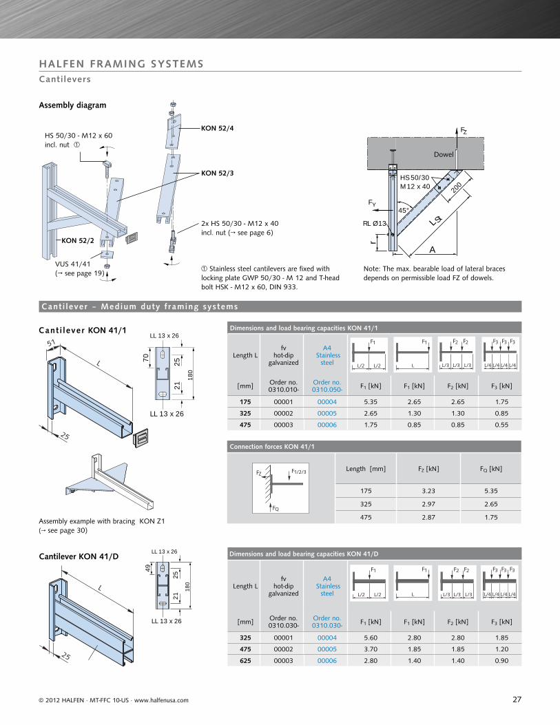
Dimensions and load bearing capacities KON 41/1
Length Lfv
hot-dip galvanized
A4 Stainless
steel
[mm] Order no. 0310.010-
Order no. 0310.050- F1 [kN] F1 [kN] F2 [kN] F3 [kN]
175 00001 00004 5.35 2.65 2.65 1.75
325 00002 00005 2.65 1.30 1.30 0.85
475 00003 00006 1.75 0.85 0.85 0.55
Dimensions and load bearing capacities KON 41/D
Length Lfv
hot-dip galvanized
A4 Stainless
steel
[mm] Order no. 0310.030-
Order no. 0310.030- F1 [kN] F1 [kN] F2 [kN] F3 [kN]
325 00001 00004 5.60 2.80 2.80 1.85
475 00002 00005 3.70 1.85 1.85 1.20
625 00003 00006 2.80 1.40 1.40 0.90
Connection forces KON 41/1
1/2/3F
QF
ZFLength [mm] FZ [kN] FQ [kN]
175 3.23 5.35
325 2.97 2.65
475 2.87 1.75
51
L
25
25
L
ZF
FY
RL Ø13
r
M12 x 40HS 50/30
45°
200
L St
A
Dowel
LL 13 x 26
180
2521
LL 13 x 26
70
LL 13 x 26
180
2521
LL 13 x 26
49
L/2L/2
1F
L
1F
L/3L/3L/3
2F2F
L/4L/4 L/4 L/4
3F3F 3F
L/2L/2
1F
L
1F
L/3L/3L/3
2F2F
L/4L/4 L/4 L/4
3F3F 3F
© 2012 HALFEN · MT-FFC 10-US · www.halfenusa.com
Cant i lever KON 41/1
Cantilever KON 41/D
Cant i lever ‒ Medium duty f raming systems
Note: The max. bearable load of lateral braces depends on permissible load FZ of dowels.
Assembly example with bracing KON Z1 (→ see page 30)
Stainless steel cantilevers are fixed with locking plate GWP 50/30 - M 12 and T-head bolt HSK - M12 x 60, DIN 933.
Assembly diagram
KON 52/4HS 50/30 - M12 x 60incl. nut
VUS 41/41(→ see page 19)
2x HS 50/30 - M12 x 40incl. nut (→ see page 6)
KON 52/3
KON 52/2
HALFEN FRAMING SYSTEMSCantilevers
28
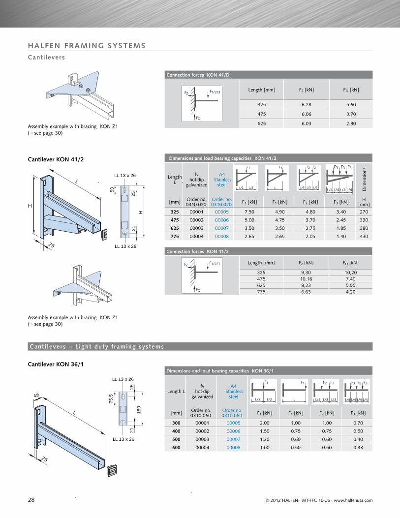
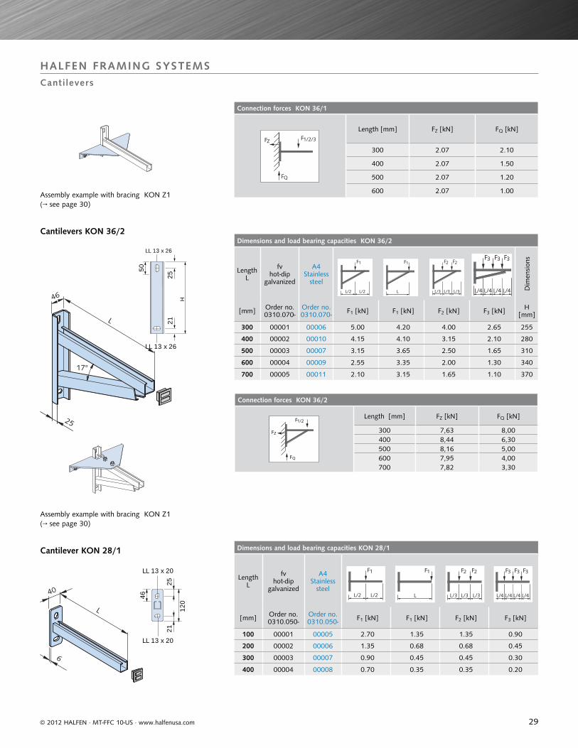
Dimensions and load bearing capacities KON 36/1
Length Lfv
hot-dip galvanized
A4 Stainless
steel
[mm] Order no. 0310.060-
Order no.0310.060- F1 [kN] F1 [kN] F2 [kN] F3 [kN]
300 00001 00005 2.00 1.00 1.00 0.70
400 00002 00006 1.50 0.75 0.75 0.50
500 00003 00007 1.20 0.60 0.60 0.40
600 00004 00008 1.00 0.50 0.50 0.33
Dimensions and load bearing capacities KON 41/2
Length L
fv hot-dip
galvanized
A4 Stainless
steel
Dim
ensi
ons
[mm] Order no. 0310.020-
Order no. 0310.020- F1 [kN] F1 [kN] F2 [kN] F3 [kN] H
[mm]
325 00001 00005 7.50 4.90 4.80 3.40 270
475 00002 00006 5.00 4.75 3.70 2.45 330
625 00003 00007 3.50 3.50 2.75 1.85 380
775 00004 00008 2.65 2.65 2.05 1.40 430
Connection forces KON 41/2
1/2/3F
QF
ZF Length [mm] FZ [kN] FQ [kN]
325 9,30 10,20475 10,16 7,40625 8,23 5,55775 6,63 4,20
Connection forces KON 41/D
1/2/3F
QF
ZFLength [mm] FZ [kN] FQ [kN]
325 6.28 5.60
475 6.06 3.70
625 6.03 2.80
LL 13 x 26
LL 13 x 26
H
50
2521
LL 13 x 26
LL 13 x 26
180
75, 5
2521
25
L
H
L/2L/2
1F
L/3L/3L/3
2F2F
L
1F
L/4L/4 L/4 L/4
3F3F 3F
46
25
L
L/2L/2
1F
L
1F
L/3L/3L/3
2F2F
L/4L/4 L/4 L/4
3F3F 3F
© 2012 HALFEN · MT-FFC 10-US · www.halfenusa.com
Cantilever KON 41/2
Assembly example with bracing KON Z1(→ see page 30)
Assembly example with bracing KON Z1(→ see page 30)
HALFEN FRAMING SYSTEMSCantilevers
Cant i levers – L ight duty f raming systems
Cantilever KON 36/1
29
Connection forces KON 36/2
Length [mm] FZ [kN] FQ [kN]
300 7,63 8,00400 8,44 6,30500 8,16 5,00600 7,95 4,00700 7,82 3,30
Connection forces KON 36/1
1/2/3F
QF
ZF
Length [mm] FZ [kN] FQ [kN]
300 2.07 2.10
400 2.07 1.50
500 2.07 1.20
600 2.07 1.00
Dimensions and load bearing capacities KON 36/2
Length L
fv hot-dip
galvanized
A4Stainless
steel
Dim
ensi
ons
[mm] Order no. 0310.070-
Order no. 0310.070- F1 [kN] F1 [kN] F2 [kN] F3 [kN] H
[mm]
300 00001 00006 5.00 4.20 4.00 2.65 255
400 00002 00010 4.15 4.10 3.15 2.10 280
500 00003 00007 3.15 3.65 2.50 1.65 310
600 00004 00009 2.55 3.35 2.00 1.30 340
700 00005 00011 2.10 3.15 1.65 1.10 370
Dimensions and load bearing capacities KON 28/1
Length L
fv hot-dip
galvanized
A4Stainless
steel
[mm] Order no. 0310.050-
Order no. 0310.050- F1 [kN] F1 [kN] F2 [kN] F3 [kN]
100 00001 00005 2.70 1.35 1.35 0.90
200 00002 00006 1.35 0.68 0.68 0.45
300 00003 00007 0.90 0.45 0.45 0.30
400 00004 00008 0.70 0.35 0.35 0.20
LL 13 x 20
25
46
21
120
LL 13 x 20
LL 13 x 26
H
2521
LL 13 x 26
50
6
40
L
17°
46
25
L
L/2L/2
1F
L/3L/3L/3
2F2F
L
1F
L/4L/4 L/4 L/4
3F3F 3F
L/2L/2
1F
L
1F
L/3L/3L/3
2F2F
L/4L/4 L/4 L/4
3F3F 3F
© 2012 HALFEN · MT-FFC 10-US · www.halfenusa.com
Cantilever KON 28/1
HALFEN FRAMING SYSTEMS Cantilevers
Cantilevers KON 36/2
Assembly example with bracing KON Z1(→ see page 30)
Assembly example with bracing KON Z1(→ see page 30)
30
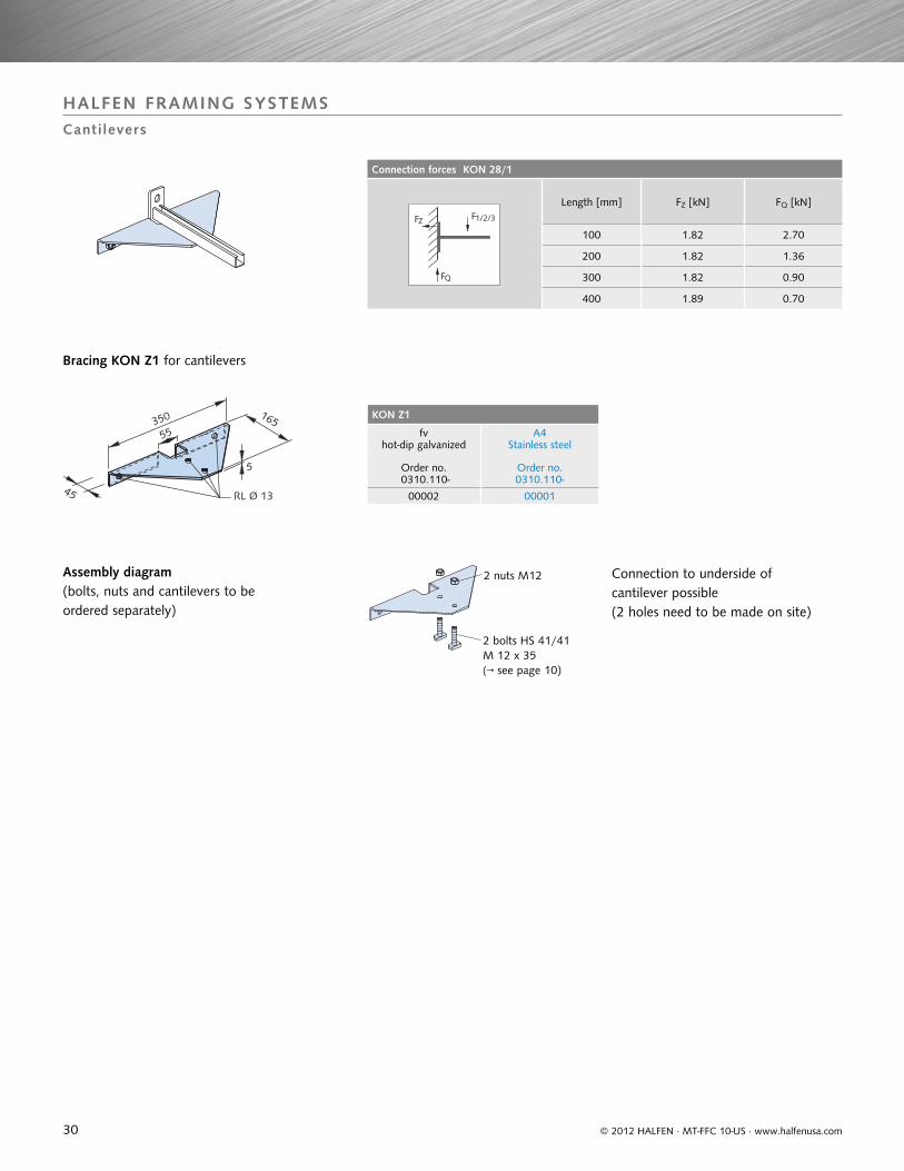
Connection forces KON 28/1
1/2/3F
QF
ZF
Length [mm] FZ [kN] FQ [kN]
100 1.82 2.70
200 1.82 1.36
300 1.82 0.90
400 1.89 0.70
KON Z1
fv hot-dip galvanized
A4 Stainless steel
Order no. 0310.110-
Order no.0310.110-
00002 0000145
55
165
5
350
RL Ø 13
2 bolts HS 41/41M 12 x 35 (→ see page 10)
2 nuts M12
© 2012 HALFEN · MT-FFC 10-US · www.halfenusa.com
HALFEN FRAMING SYSTEMSCantilevers
Bracing KON Z1 for cantilevers
Assembly diagram(bolts, nuts and cantilevers to be ordered separately)
Connection to underside of cantilever possible (2 holes need to be made on site)
31© 2012 HALFEN · MT-FFC 10-US · www.halfenusa.com
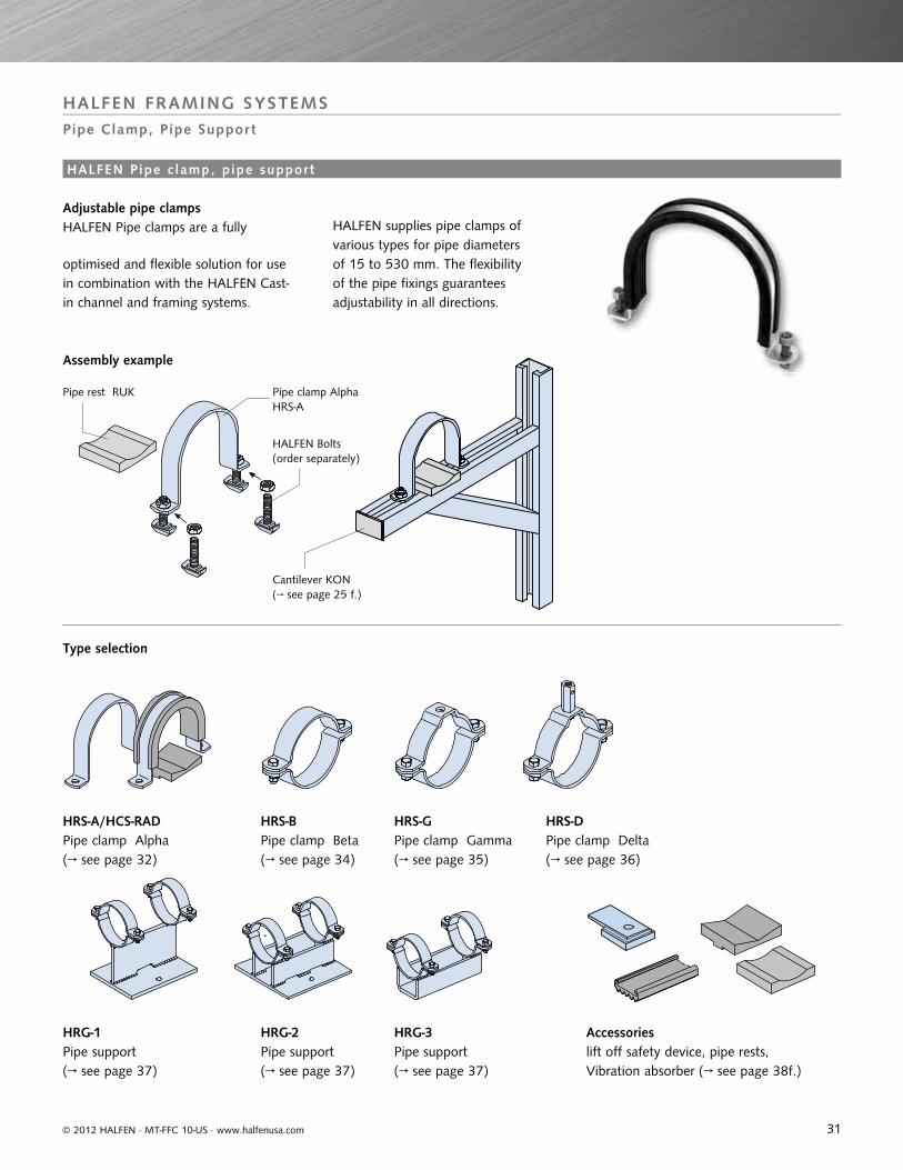
Assembly example
Pipe clamp AlphaHRS-A
Pipe rest RUK
HALFEN Bolts (order separately)
Cantilever KON(→ see page 25 f.)
HALFEN FRAMING SYSTEMSPipe Clamp, Pipe Support
HALFEN Pipe c lamp, p ipe support
Adjustable pipe clampsHALFEN Pipe clamps are a fully
optimised and flexible solution for use in combination with the HALFEN Cast-in channel and framing systems.
Type selection
HALFEN supplies pipe clamps of various types for pipe diameters of 15 to 530 mm. The flexibility of the pipe fixings guarantees adjustability in all directions.
HRS-A/HCS-RADPipe clamp Alpha(→ see page 32)
HRG-1Pipe support(→ see page 37)
HRS-BPipe clamp Beta(→ see page 34)
HRG-2Pipe support(→ see page 37)
HRS-GPipe clamp Gamma(→ see page 35)
HRG-3Pipe support(→ see page 37)
Accessorieslift off safety device, pipe rests, Vibration absorber (→ see page 38f.)
HRS-DPipe clamp Delta(→ see page 36)
32
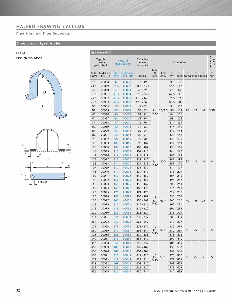
Pipe clamp HRS-A
Type fv hot-dip
galvanized
Type A4Stainless steel
Clamping range
from - toDimensions
pre-
tens
ion
valu
e
Ø D [mm]
Order no.0311.010-
Ø D [mm]
Order no.0311.010- [mm]
hole Ø
[mm]b/d
[mm]L
[mm]K
[mm]a
[mm]c
[mm]r
[mm]v
[mm]
17 00048 17 00001 16 - 19
11 for
M1025/2.5
51 77
30 13 16 2.75
21.5 00049 21.5 00002 20.5 - 23.5 55.5 81.527 00050 27 00003 26 - 29 61 87
33.5 00051 33.5 00004 32.5 - 35.5 67.5 93.542.5 00052 42.5 00005 41.5 - 44.5 76.5 102.548.5 00053 48.5 00006 47.5 - 50.5 82.5 108.550 00054 50 00007 49 - 52 84 11056 00055 56 00008 55 - 58 90 11660 00056 60 00009 59 - 62 94 12064 00057 64 00010 63 - 66 98 12477 00058 77 00011 76 - 79 111 13780 00059 80 00012 79 - 82 114 14084 00060 84 00013 83 - 86 118 14489 00061 89 00014 88 - 91 123 14996 00062 96 00015 95 - 98 130 156100 00063 100 00016 98 - 102
11for
M1030/4
134 160
30 13 19 4
105 00064 105 00017 103 - 107 139 165110 00065 110 00018 108 - 112 144 170116 00066 116 00019 114 - 118 150 176125 00067 125 00020 123 - 127 159 185131 00068 131 00021 129 - 133 165 191137 00069 137 00022 135 - 139 171 197141 00070 141 00023 139 - 143 175 201150 00071 150 00024 148 - 152 184 210157 00072 157 00025 155 - 159 191 217160 00073 160 00026 158 - 162
13for
M1240/4
208 240
40 16 24 4
168 00074 168 00027 166 - 170 216 248176 00075 176 00028 174 - 178 224 256185 00076 185 00029 183 - 187 233 265200 00077 200 00030 198 - 202 248 280212 00078 212 00031 210 - 214 260 292218 00079 218 00032 216 - 220 266 298225 00080 225 00033 223 - 227 273 305
235 00081 235 00034 233 - 237 283 315
267 00083 267 00035 265 - 269
17for
M1650/5
317 367
50 25 36 5273 00084 273 00036 271 - 275 323 373285 00085 285 00037 283 - 287 335 385326 00086 326 00038 324 - 328 376 426340 00087 340 00039 338 - 342 390 440
355 00088 355 00040 353 - 357
17for
M1650/5
405 455
50 25 36 5
400 00089 400 00041 398 - 402 450 500406 00090 406 00042 404 - 408 456 506420 00091 420 00043 418 - 422 470 520429 00092 429 00044 427 - 431 479 529508 00093 508 00045 506 - 510 558 608525 00094 525 00046 523 - 527 575 625532 00095 532 00047 530 - 534 582 635
D
v d
b
K
L cc
a
r
Loch-Ø
D
hole
© 2012 HALFEN · MT-FFC 10-US · www.halfenusa.com
HRS-A Pipe clamp Alpha
HALFEN FRAMING SYSTEMSPipe Clamps, Pipe Supports
P ipe c lamp Type Alpha
33
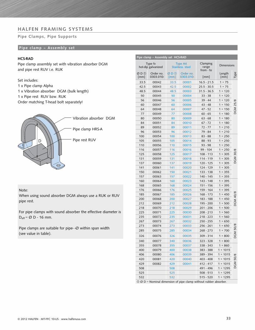
Pipe clamp – Assembly set HCS-RAD
Type fv hot-dip galvanized
Type A4Stainless. steel
Clamping range
from - to
[mm]
Dimensions
Ø D [mm]
Order no.0303.010-
Ø D [mm]
Order no.0303.010-
Length[mm] Ty
pe
33.5 00042 33.5 00001 16.5 - 21.5 1 × 75
DG
M 2
5/8
42.5 00043 42.5 00002 25.5 - 30.5 1 × 75 48.5 00044 48.5 00003 31.5 - 36.5 1 × 120
50 00045 50 00004 33 - 38 1 × 120
56 00046 56 00005 39 - 44 1 × 120 60 00047 60 00006 43 - 48 1 × 150 64 00048 64 00007 47 - 52 1 × 150
77 00049 77 00008 60 - 65 1 × 180
80 00050 80 00009 63 - 68 1 × 180 84 00051 84 00010 67 - 72 1 × 180 89 00052 89 00011 72 - 77 1 × 210 96 00053 96 00012 79 - 84 1 × 210100 00054 100 00013 83 - 88 1 × 250
DG
M 3
0/8
105 00055 105 00014 88 - 93 1 × 250110 00056 110 00015 93 - 98 1 × 250116 00057 116 00016 99 - 104 1 × 250125 00058 125 00017 108 - 113 1 × 305131 00059 131 00018 114 - 119 1 × 305137 00060 137 00019 120 - 125 1 × 305141 00061 141 00020 124 - 129 1 × 305150 00062 150 00021 133 - 138 1 × 355157 00063 157 00022 140 - 145 1 × 355160 00064 160 00023 143 - 148 1 × 395
DG
M 4
0/8
168 00065 168 00024 151 - 156 1 × 395176 00066 176 00025 159 - 164 1 × 395185 00067 185 00026 168 - 173 1 × 450200 00068 200 00027 183 - 188 1 × 450212 00069 212 00028 195 - 200 1 × 500218 00070 218 00029 201 - 206 1 × 500225 00071 225 00030 208 - 213 1 × 560235 00072 235 00031 218 - 223 1 × 560267 00073 267 00032 250 - 255 1 × 650
DG
M 5
0/8273 00074 273 00033 256 - 261 1 × 650
285 00075 285 00034 268 - 273 1 × 700
326 00076 326 00035 309 - 314 1 × 800
340 00077 340 00036 323 - 328 1 × 800355 00078 355 00037 338 - 343 1 × 860
DG
M 5
0/8
400 00079 400 00038 383 - 388 1 × 1015406 00080 406 00039 389 - 394 1 × 10¹⁵
420 00081 420 00040 403 - 408 1 × 10¹⁵
429 00082 429 00041 412 - 417 1 × 1015508 508 491 - 496 1 × 1295525 525 508 - 513 1 × 1295532 532 515 - 520 1 × 1295
Ø D = Nominal dimension of pipe clamp without rubber absorber.
D
© 2012 HALFEN · MT-FFC 10-US · www.halfenusa.com
HCS-RADPipe clamp assembly set with vibration absorber DGM and pipe rest RUV i.e. RUK
Set includes:1 x Pipe clamp Alpha1 x Vibration absorber DGM (bulk length)1 x Pipe rest RUV bzw. RUK
Vibration absorber DGM
Order matching T-head bolt separately!
Pipe clamp HRS-A
Pipe rest RUV
Note:When using sound absorber DGM always use a RUK or RUV pipe rest.
For pipe clamps with sound absorber the effective diameter is Deff = Ø D - 16 mm.
Pipe clamps are suitable for pipe- -Ø within span width(see value in table).
HALFEN FRAMING SYSTEMSPipe Clamps, Pipe Supports
P ipe c lamp – Assembly set
34
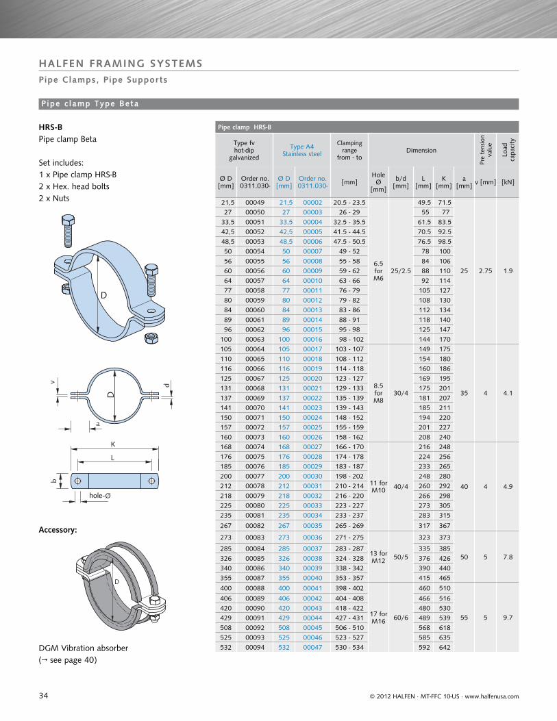
Pipe clamp HRS-B
Type fv hot-dip
galvanized
Type A4Stainless steel
Clamping range
from - toDimension
Pre
tens
ion
valu
e
Load
ca
paci
ty
Ø D [mm]
Order no.0311.030-
Ø D [mm]
Order no.0311.030- [mm]
Hole Ø
[mm]
b/d[mm]
L [mm]
K [mm]
a [mm] v [mm] [kN]
21,5 00049 21,5 00002 20.5 - 23.5
6.5 for M6
25/2.5
49.5 71.5
25 2.75 1.9
27 00050 27 00003 26 - 29 55 77 33,5 00051 33,5 00004 32.5 - 35.5 61.5 83.5 42,5 00052 42,5 00005 41.5 - 44.5 70.5 92.5 48,5 00053 48,5 00006 47.5 - 50.5 76.5 98.5 50 00054 50 00007 49 - 52 78 100 56 00055 56 00008 55 - 58 84 106 60 00056 60 00009 59 - 62 88 110 64 00057 64 00010 63 - 66 92 114 77 00058 77 00011 76 - 79 105 127 80 00059 80 00012 79 - 82 108 130 84 00060 84 00013 83 - 86 112 134 89 00061 89 00014 88 - 91 118 140 96 00062 96 00015 95 - 98 125 147100 00063 100 00016 98 - 102 144 170105 00064 105 00017 103 - 107
8.5 for M8
30/4
149 175
35 4 4.1
110 00065 110 00018 108 - 112 154 180116 00066 116 00019 114 - 118 160 186125 00067 125 00020 123 - 127 169 195131 00068 131 00021 129 - 133 175 201137 00069 137 00022 135 - 139 181 207141 00070 141 00023 139 - 143 185 211150 00071 150 00024 148 - 152 194 220157 00072 157 00025 155 - 159 201 227160 00073 160 00026 158 - 162 208 240168 00074 168 00027 166 - 170
11 for M10 40/4
216 248
40 4 4.9
176 00075 176 00028 174 - 178 224 256185 00076 185 00029 183 - 187 233 265200 00077 200 00030 198 - 202 248 280212 00078 212 00031 210 - 214 260 292218 00079 218 00032 216 - 220 266 298225 00080 225 00033 223 - 227 273 305235 00081 235 00034 233 - 237 283 315
267 00082 267 00035 265 - 269 317 367
273 00083 273 00036 271 - 275
13 for M12 50/5
323 373
50 5 7.8285 00084 285 00037 283 - 287 335 385326 00085 326 00038 324 - 328 376 426340 00086 340 00039 338 - 342 390 440355 00087 355 00040 353 - 357 415 465
400 00088 400 00041 398 - 402
17 for M16 60/6
460 510
55 5 9.7
406 00089 406 00042 404 - 408 466 516420 00090 420 00043 418 - 422 480 530429 00091 429 00044 427 - 431 489 539508 00092 508 00045 506 - 510 568 618525 00093 525 00046 523 - 527 585 635
532 00094 532 00047 530 - 534 592 642
D
D
v d
a
b
K
L
Loch-Ø
D
hole
© 2012 HALFEN · MT-FFC 10-US · www.halfenusa.com
HALFEN FRAMING SYSTEMSPipe Clamps, Pipe Supports
HRS-BPipe clamp Beta
Set includes:1 x Pipe clamp HRS-B2 x Hex. head bolts2 x Nuts
DGM Vibration absorber(→ see page 40)
Pipe c lamp Type Beta
Accessory:
35
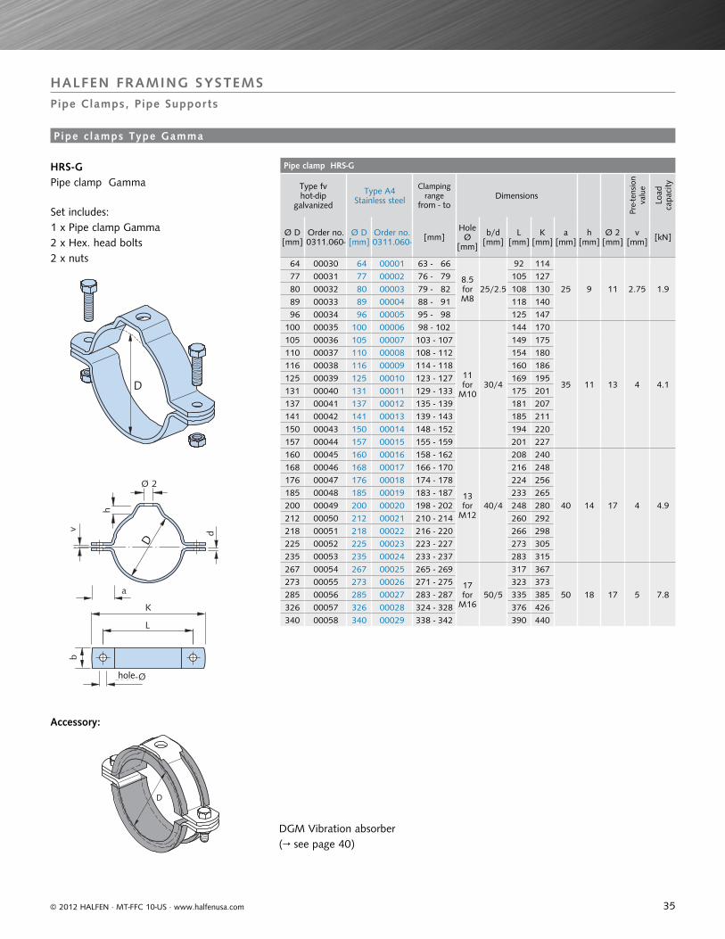
Pipe clamp HRS-G
Type fv hot-dip
galvanized
Type A4Stainless steel
Clamping range
from - toDimensions
Pre-
tens
ion
valu
e
Load
ca
paci
ty
Ø D [mm]
Order no.0311.060-
Ø D [mm]
Order no.0311.060- [mm]
Hole Ø
[mm]
b/d[mm]
L [mm]
K [mm]
a [mm]
h [mm]
Ø 2 [mm]
v [mm] [kN]
64 00030 64 00001 63 - 66
8.5 for M8
25/2.5
92 114
25 9 11 2.75 1.9 77 00031 77 00002 76 - 79 105 127 80 00032 80 00003 79 - 82 108 130 89 00033 89 00004 88 - 91 118 140 96 00034 96 00005 95 - 98 125 147100 00035 100 00006 98 - 102
11 for
M1030/4
144 170
35 11 13 4 4.1
105 00036 105 00007 103 - 107 149 175110 00037 110 00008 108 - 112 154 180116 00038 116 00009 114 - 118 160 186125 00039 125 00010 123 - 127 169 195131 00040 131 00011 129 - 133 175 201137 00041 137 00012 135 - 139 181 207141 00042 141 00013 139 - 143 185 211150 00043 150 00014 148 - 152 194 220157 00044 157 00015 155 - 159 201 227160 00045 160 00016 158 - 162
13 for
M1240/4
208 240
40 14 17 4 4.9
168 00046 168 00017 166 - 170 216 248176 00047 176 00018 174 - 178 224 256185 00048 185 00019 183 - 187 233 265200 00049 200 00020 198 - 202 248 280212 00050 212 00021 210 - 214 260 292218 00051 218 00022 216 - 220 266 298225 00052 225 00023 223 - 227 273 305235 00053 235 00024 233 - 237 283 315267 00054 267 00025 265 - 269
17 for
M1650/5
317 367
50 18 17 5 7.8
273 00055 273 00026 271 - 275 323 373285 00056 285 00027 283 - 287 335 385326 00057 326 00028 324 - 328 376 426
340 00058 340 00029 338 - 342 390 440
D
b
K
L
h
Ø 2
D
v d
a
Loch-Ø
D
hole
© 2012 HALFEN · MT-FFC 10-US · www.halfenusa.com
DGM Vibration absorber (→ see page 40)
HALFEN FRAMING SYSTEMSPipe Clamps, Pipe Supports
HRS-GPipe clamp Gamma
Set includes:1 x Pipe clamp Gamma2 x Hex. head bolts2 x nuts
Pipe c lamps Type Gamma
Accessory:
36
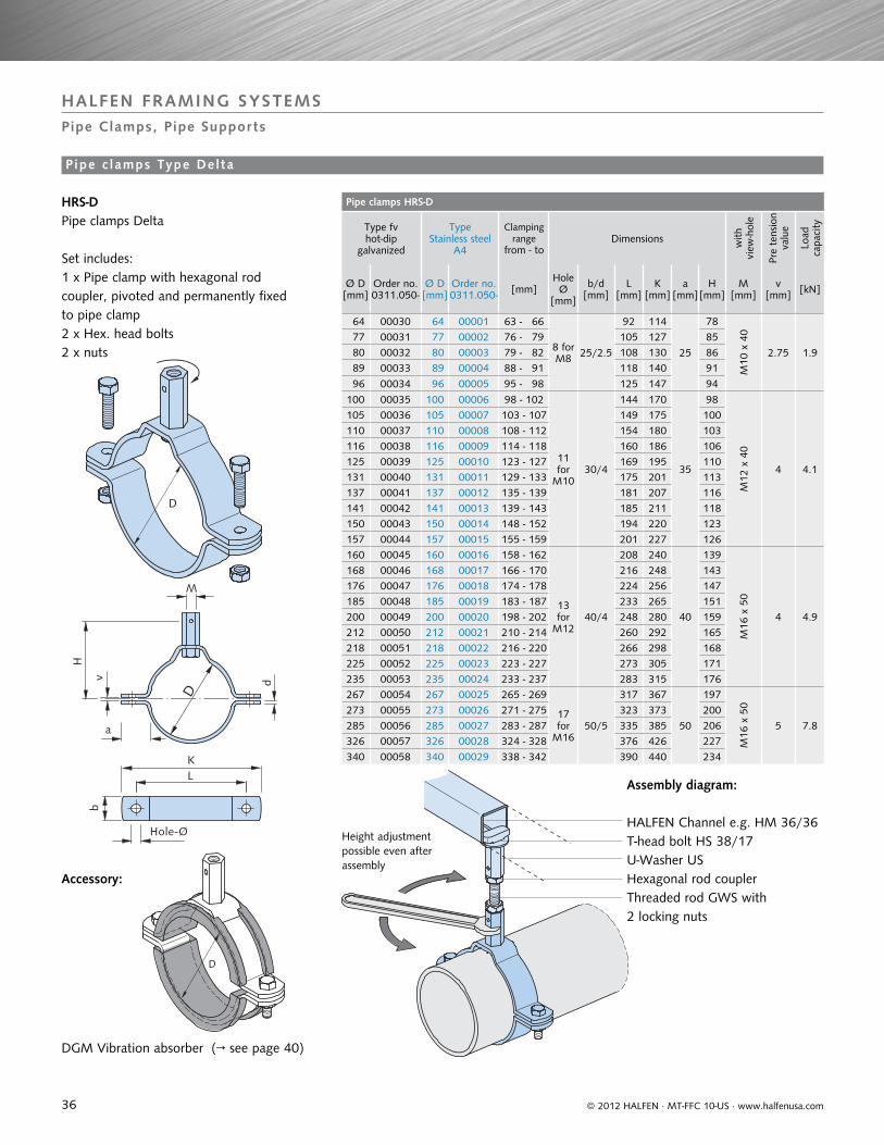
Pipe clamps HRS-D
Type fv hot-dip
galvanized
TypeStainless steel
A4
Clamping range
from - toDimensions w
ithvi
ew-h
ole
Pre
tens
ion
valu
e
Load
ca
paci
ty
Ø D [mm]
Order no.0311.050-
Ø D [mm]
Order no.0311.050- [mm]
Hole Ø
[mm]
b/d[mm]
L [mm]
K [mm]
a [mm]
H [mm]
M [mm]
v [mm] [kN]
64 00030 64 00001 63 - 66
8 for M8 25/2.5
92 114
25
78
M10
x 4
0
2.75 1.9
77 00031 77 00002 76 - 79 105 127 85 80 00032 80 00003 79 - 82 108 130 86 89 00033 89 00004 88 - 91 118 140 91
96 00034 96 00005 95 - 98 125 147 94
100 00035 100 00006 98 - 102
11 for
M1030/4
144 170
35
98
M12
x 4
0
4 4.1
105 00036 105 00007 103 - 107 149 175 100110 00037 110 00008 108 - 112 154 180 103116 00038 116 00009 114 - 118 160 186 106125 00039 125 00010 123 - 127 169 195 110131 00040 131 00011 129 - 133 175 201 113137 00041 137 00012 135 - 139 181 207 116141 00042 141 00013 139 - 143 185 211 118150 00043 150 00014 148 - 152 194 220 123157 00044 157 00015 155 - 159 201 227 126160 00045 160 00016 158 - 162
13 for
M1240/4
208 240
40
139
M16
x 5
0
4 4.9
168 00046 168 00017 166 - 170 216 248 143176 00047 176 00018 174 - 178 224 256 147185 00048 185 00019 183 - 187 233 265 151200 00049 200 00020 198 - 202 248 280 159212 00050 212 00021 210 - 214 260 292 165218 00051 218 00022 216 - 220 266 298 168225 00052 225 00023 223 - 227 273 305 171235 00053 235 00024 233 - 237 283 315 176267 00054 267 00025 265 - 269
17 for
M1650/5
317 367
50
197
M16
x 5
0
5 7.8
273 00055 273 00026 271 - 275 323 373 200285 00056 285 00027 283 - 287 335 385 206326 00057 326 00028 324 - 328 376 426 227
340 00058 340 00029 338 - 342 390 440 234
D
b
KL
H
M
D
v d
a
Hole-Ø
D
© 2012 HALFEN · MT-FFC 10-US · www.halfenusa.com
HRS-DPipe clamps Delta
Set includes: 1 x Pipe clamp with hexagonal rod coupler, pivoted and permanently fixed to pipe clamp2 x Hex. head bolts 2 x nuts
Assembly diagram:
HALFEN Channel e.g. HM 36/36T-head bolt HS 38/17U-Washer US
Threaded rod GWS with 2 locking nuts
Hexagonal rod coupler
Height adjustment possible even after assembly
HALFEN FRAMING SYSTEMSPipe Clamps, Pipe Supports
DGM Vibration absorber (→ see page 40)
Pipe c lamps Type Del ta
Accessory:
37
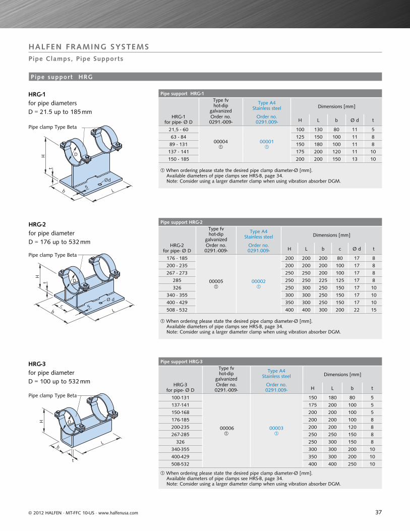
Pipe support HRG-1
HRG-1 for pipe- Ø D
Type fvhot-dip
galvanized
Type A4Stainless steel Dimensions [mm]
Order no.0291.-009-
Order no.0291.009- H L b Ø d t
21,5 - 60
00004
00001
100 130 80 11 5
63 - 84 125 150 100 11 8
89 - 131 150 180 100 11 8
137 - 141 175 200 120 11 10
150 - 185 200 200 150 13 10
When ordering please state the desired pipe clamp diameter-Ø [mm]. Available diameters of pipe clamps see HRS-B, page 34. Note: Consider using a larger diameter clamp when using vibration absorber DGM.
Pipe support HRG-2
HRG-2 for pipe- Ø D
Type fvhot-dip
galvanized
Type A4Stainless steel Dimensions [mm]
Order no.0291.-009-
Order no.0291.009- H L b c Ø d t
176 - 185
00005
00002
200 200 200 80 17 8
200 - 235 200 200 200 100 17 8
267 - 273 250 250 200 100 17 8
285 250 250 225 125 17 8
326 250 300 250 150 17 10
340 - 355 300 300 250 150 17 10
400 - 429 350 300 250 150 17 10
508 - 532 400 400 300 200 22 15
When ordering please state the desired pipe clamp diameter-Ø [mm]. Available diameters of pipe clamps see HRS-B, page 34. Note: Consider using a larger diameter clamp when using vibration absorber DGM.
Pipe support HRG-3
HRG-3 for pipe- Ø D
Type fvhot-dip
galvanized
Type A4Stainless steel Dimensions [mm]
Order no.0291.-009-
Order no.0291.009- H L b t
100-131
00006
00003
150 180 80 5
137-141 175 200 100 5
150-168 200 200 100 5
176-185 200 200 100 8
200-235 200 200 120 8
267-285 250 250 150 8
326 250 300 150 8
340-355 300 300 200 10
400-429 350 300 200 10
508-532 400 400 250 10
When ordering please state the desired pipe clamp diameter-Ø [mm]. Available diameters of pipe clamps see HRS-B, page 34. Note: Consider using a larger diameter clamp when using vibration absorber DGM.
Ød
H
t
5b L
D
5
Ø dc
H
t
b
D
L
t
b
H
L
D
© 2012 HALFEN · MT-FFC 10-US · www.halfenusa.com
HALFEN FRAMING SYSTEMSPipe Clamps, Pipe Supports
HRG-1 for pipe diameters D = 21.5 up to 185 mm
HRG-2 for pipe diameter D = 176 up to 532 mm
Pipe clamp Type Beta
Pipe clamp Type Beta
Pipe clamp Type Beta
HRG-3 for pipe diameter D = 100 up to 532 mm
Pipe support HRG
38
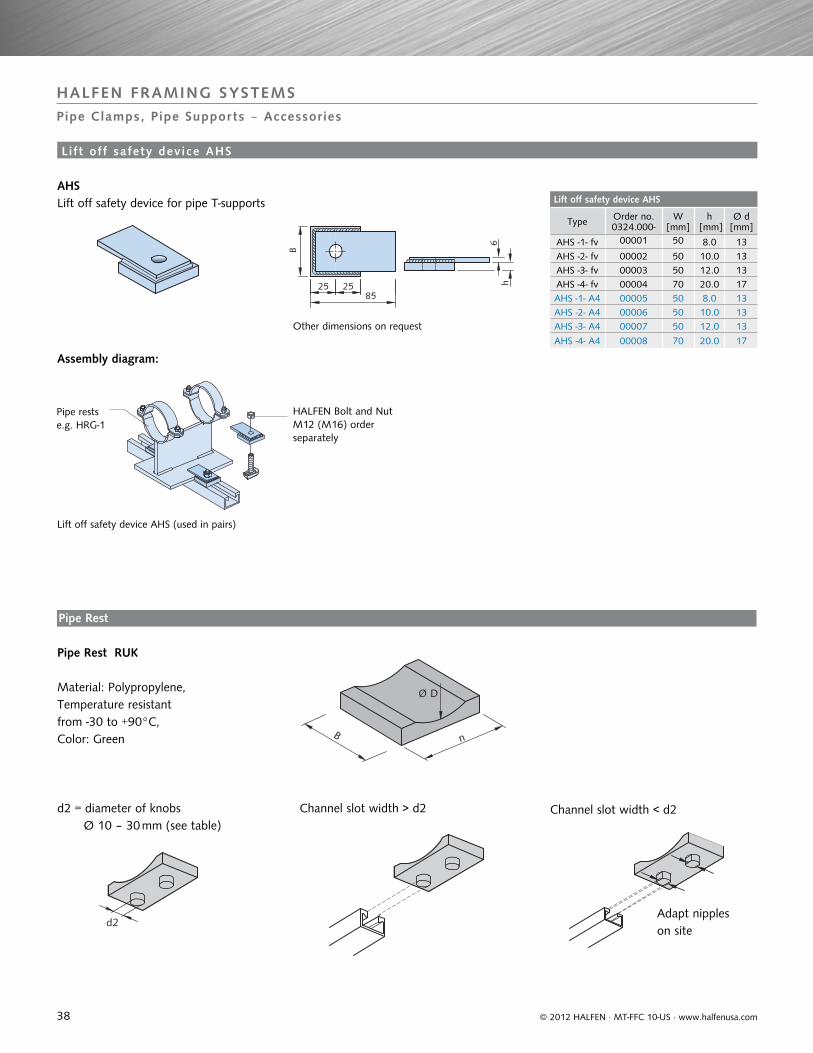
Lift off safety device AHS
Type Order no. 0324.000-
W[mm]
h [mm]
Ø d[mm]
AHS -1- fv 00001 50 8.0 13AHS -2- fv 00002 50 10.0 13AHS -3- fv 00003 50 12.0 13AHS -4- fv 00004 70 20.0 17AHS -1- A4 00005 50 8.0 13AHS -2- A4 00006 50 10.0 13AHS -3- A4 00007 50 12.0 13
AHS -4- A4 00008 70 20.0 17
25 25B
85
6h
Ø D
B n
d2
© 2012 HALFEN · MT-FFC 10-US · www.halfenusa.com
HALFEN FRAMING SYSTEMSPipe Clamps, Pipe Supports ‒ Accessories
AHS Lift off safety device for pipe T-supports
Other dimensions on request
Assembly diagram:
Lift off safety device AHS (used in pairs)
Pipe rests e.g. HRG-1
HALFEN Bolt and Nut M12 (M16) order separately
L i f t of f safety dev ice AHS
Pipe Rest
Material: Polypropylene, Temperature resistant from -30 to +90°C, Color: Green
d2 = diameter of knobs Ø 10 – 30 mm (see table)
Channel slot width > d2 Channel slot width < d2
Adapt nipples on site
Pipe Rest RUK
39
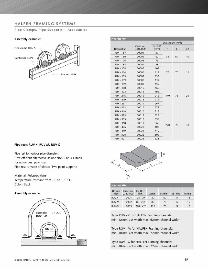
Pipe rest RUK
DescriptionOrder no. 0316.000-
Dimensions [mm]for Ø D [mm] n B d2
RUK - 57 00001 57
38 50 10RUK - 60 00002 60
RUK - 76 00003 76
RUK - 88 00004 88
75 70 15
RUK - 108 00005 108
RUK - 114 00006 114
RUK - 133 00007 133
RUK - 139 00008 139
RUK - 159 00009 159
140 75 25
RUK - 168 00010 168
RUK - 193 00011 193
RUK - 216 00012 216
RUK - 219 00013 219
RUK - 267 00014 267
RUK - 273 00015 273
RUK - 318 00016 318
220 75 30
RUK - 323 00017 323
RUK - 355 00018 355
RUK - 368 00019 368
RUK - 406 00020 406
RUK - 419 00021 419
RUK - 508 00022 508
RUK - 521 00023 521
Pipe rest RUV
Descrip-tion
Order no. 0317.000-
for Ø D [mm] L [mm] B [mm] N [mm] H [mm]
RUV-K 0001 25 - 79 30 50 11 11
RUV-M 0002 80 - 269 80 70 17 15
RUV-G 0003 270 - 420 120 70 17 16
N
H
B L
RUV - M
DN 80
DN 200example:.
© 2012 HALFEN · MT-FFC 10-US · www.halfenusa.com
HALFEN FRAMING SYSTEMSPipe Clamps, Pipe Supports ‒ Accessories
Pipe rest RUK
Cantilever KON
Pipe clamp HRS-A
Pipe rest for various pipe diameters.Cost efficient alternative as one size RUV is suitable for numerous pipe sizes. Pipe rest is made of plastic (Two-point-support).
Material: Polypropylene, Temperature resistant from -30 to +90° C, Color: Black
Assembly example:
Assembly example:
Type RUV - K for HALFEN Framing channels: min. 12 mm slot width max. 52 mm channel width
Type RUV - M for HALFEN Framing channels: min. 18 mm slot width max. 72 mm channel width
Type RUV - G for HALFEN Framing channels: min. 18 mm slot width max. 72 mm channel width
Pipe rests RUV-K, RUV-M, RUV-G
40
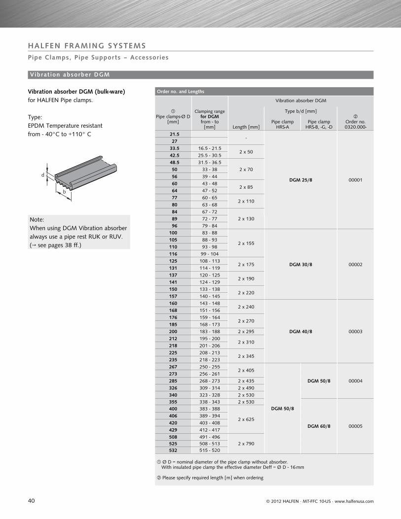
Order no. and Lengths
Pipe clamps-Ø D
[mm]
Clamping range for DGM from - to
[mm]
Vibration absorber DGM
Length [mm]
Type b/d [mm]
Order no. 0320.000-
Pipe clamp HRS-A
Pipe clamp HRS-B, -G, -D
21.5 -
DGM 25/8 00001
27 33.5 16.5 - 21.5
2 x 50 42.5 25.5 - 30.5 48.5 31.5 - 36.5
2 x 70 50 33 - 38 56 39 - 44 60 43 - 48
2 x 85 64 47 - 52 77 60 - 65
2 x 110 80 63 - 68 84 67 - 72
2 x 130 89 72 - 77 96 79 - 84100 83 - 88
2 x 155
DGM 30/8 00002
105 88 - 93110 93 - 98116 99 - 104125 108 - 113
2 x 175131 114 - 119137 120 - 125
2 x 190141 124 - 129150 133 - 138
2 x 220157 140 - 145160 143 - 148
2 x 240
DGM 40/8 00003
168 151 - 156176 159 - 164
2 x 270185 168 - 173200 183 - 188 2 x 295212 195 - 200
2 x 310218 201 - 206225 208 - 213
2 x 345235 218 - 223267 250 - 255
2 x 405
DGM 50/8
DGM 50/8 00004
273 256 - 261285 268 - 273 2 x 435326 309 - 314 2 x 490340 323 - 328 2 x 530355 338 - 343 2 x 530
DGM 60/8 00005
400 383 - 388
2 x 625406 389 - 394420 403 - 408429 412 - 417508 491 - 496
2 x 790525 508 - 513532 515 - 520
Ø D = nominal diameter of the pipe clamp without absorber. With insulated pipe clamp the effective diameter Deff = Ø D - 16 mm
Please specify required length [m] when ordering
d
b
© 2012 HALFEN · MT-FFC 10-US · www.halfenusa.com
HALFEN FRAMING SYSTEMSPipe Clamps, Pipe Supports – Accessories
Vibrat ion absorber DGM
Vibration absorber DGM (bulk-ware)for HALFEN Pipe clamps.
Type:EPDM Temperature resistant from - 40°C to +110° C
Note:When using DGM Vibration absorber always use a pipe rest RUK or RUV. (→ see pages 38 ff.)
41
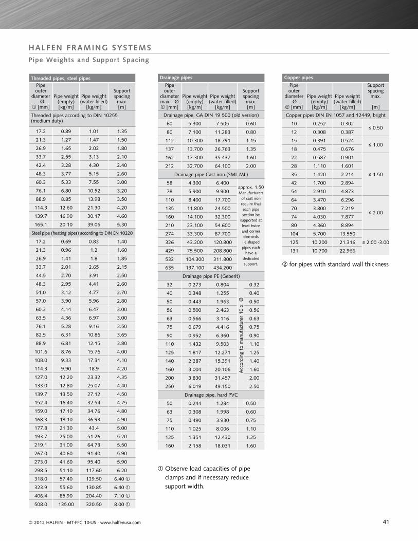
Threaded pipes, steel pipesPipe outer
diameter -Ø
[mm]
Pipe weight (empty)[kg/m]
Pipe weight (water filled)
[kg/m]
Support spacing max.[m]
Threaded pipes according to DIN 10255 (medium duty)
17.2 0.89 1.01 1.35
21.3 1.27 1.47 1.50
26.9 1.65 2.02 1.80
33.7 2.55 3.13 2.10
42.4 3.28 4.30 2.40
48.3 3.77 5.15 2.60
60.3 5.33 7.55 3.00
76.1 6.80 10.52 3.20
88.9 8.85 13.98 3.50
114.3 12.60 21.30 4.20
139.7 16.90 30.17 4.60
165.1 20.10 39.06 5.30
Steel pipe (heating pipes) according to DIN EN 10220
17.2 0.69 0.83 1.40
21.3 0.96 1.2 1.60
26.9 1.41 1.8 1.85
33.7 2.01 2.65 2.15
44.5 2.70 3.91 2.50
48.3 2.95 4.41 2.60
51.0 3.12 4.77 2.70
57.0 3.90 5.96 2.80
60.3 4.14 6.47 3.00
63.5 4.36 6.97 3.00
76.1 5.28 9.16 3.50
82.5 6.31 10.86 3.65
88.9 6.81 12.15 3.80
101.6 8.76 15.76 4.00
108.0 9.33 17.31 4.10
114.3 9.90 18.9 4.20
127.0 12.20 23.32 4.35
133.0 12.80 25.07 4.40
139.7 13.50 27.12 4.50
152.4 16.40 32.54 4.75
159.0 17.10 34.76 4.80
168.3 18.10 36.93 4.90
177.8 21.30 43.4 5.00
193.7 25.00 51.26 5.20
219.1 31.00 64.73 5.50
267.0 40.60 91.40 5.90
273.0 41.60 95.40 5.90
298.5 51.10 117.60 6.20
318.0 57.40 129.50 6.40
323.9 55.60 130.85 6.40
406.4 85.90 204.40 7.10
508.0 135.00 320.50 8.00
Drainage pipes
Pipe outer
diameter max.. -Ø [mm]
Pipe weight (empty)[kg/m]
Pipe weight (water filled)
[kg/m]
Support spacing max.[m]
Drainage pipe, GA DIN 19 500 (old version)
60 5.300 7.505 0.60
80 7.100 11.283 0.80
112 10.300 18.791 1.15
137 13.700 26.763 1.35
162 17.300 35.437 1.60
212 32.700 64.100 2.00
Drainage pipe Cast iron (SML.ML)
58 4.300 6.400approx. 1.50Manufacturers
of cast iron require that each pipe section be
supported at least twice and corner elements i.e.shaped pipes each
have a dedicated support.
78 5.900 9.900
110 8.400 17.700
135 11.800 24.500
160 14.100 32.300
210 23.100 54.600
274 33.300 87.700
326 43.200 120.800
429 75.500 208.800
532 104.300 311.800
635 137.100 434.200
Drainage pipe PE (Geberit)
32 0.273 0.804
Acc
ordi
ng t
o m
anuf
actu
rer
10 x
Ø
0.32
40 0.348 1.255 0.40
50 0.443 1.963 0.50
56 0.500 2.463 0.56
63 0.566 3.116 0.63
75 0.679 4.416 0.75
90 0.952 6.360 0.90
110 1.432 9.503 1.10
125 1.817 12.271 1.25
140 2.287 15.391 1.40
160 3.004 20.106 1.60
200 3.830 31.457 2.00
250 6.019 49.150 2.50
Drainage pipe, hard PVC
50 0.244 1.284 0.50
63 0.308 1.998 0.60
75 0.490 3.930 0.75
110 1.025 8.006 1.10
125 1.351 12.430 1.25
160 2.158 18.031 1.60
Copper pipes
Pipe outer
diameter -Ø
[mm]
Pipe weight (empty)[kg/m]
Pipe weight (water filled)
[kg/m]
Support spacing max.
[m]
Copper pipes DIN EN 1057 and 12449, bright
10 0.252 0.302≤ 0.50
12 0.308 0.387
15 0.391 0.524≤ 1.00
18 0.475 0.676
22 0.587 0.901
≤ 1.50
28 1.110 1.601
35 1.420 2.214
42 1.700 2.894
54 2.910 4.873
64 3.470 6.296
≤ 2.0070 3.800 7.219
74 4.030 7.877
80 4.360 8.894
104 5.700 13.550
≤ 2.00 -3.00125 10.200 21.316
131 10.700 22.966
HALFEN FRAMING SYSTEMSPipe Weights and Support Spacing
© 2012 HALFEN · MT-FFC 10-US · www.halfenusa.com
Observe load capacities of pipe clamps and if necessary reduce support width.
for pipes with standard wall thickness
42
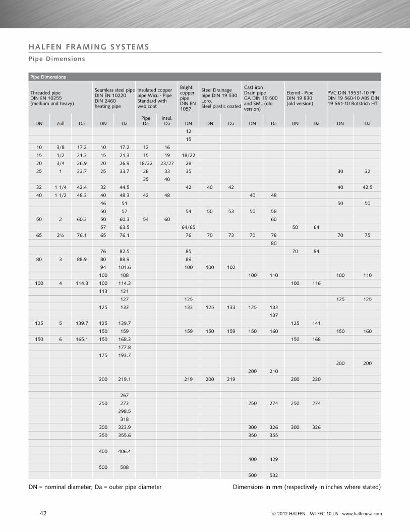
Pipe Dimensions
Threaded pipe DIN EN 10255 (medium and heavy)
Seamless steel pipe DIN EN 10220 DIN 2460 heating pipe
Insulated copper pipe Wicu - Pipe Standard with web coat
Bright copper pipe DIN EN 1057
Steel Drainage pipe DIN 19 530 Loro. Steel plastic coated
Cast iron Drain pipeGA DIN 19 500 and SML (old version)
Eternit - Pipe DIN 19 830 (old version)
PVC DIN 19531-10 PP DIN 19 560-10 ABS DIN 19 561-10 Rotstrich HT
DN Zoll Da DN DaPipeDa
insul.Da DN DN Da DN Da DN Da DN Da
12
15
10 3/8 17.2 10 17.2 12 16
15 1/2 21.3 15 21.3 15 19 18/22
20 3/4 26.9 20 26.9 18/22 23/27 28
25 1 33.7 25 33.7 28 33 35 30 32
35 40
32 1 1/4 42.4 32 44.5 42 40 42 40 42.5
40 1 1/2 48.3 40 48.3 42 48 40 48
46 51 50 50
50 57 54 50 53 50 58
50 2 60.3 50 60.3 54 60 60
57 63.5 64/65 50 64
65 2½ 76.1 65 76.1 76 70 73 70 78 70 75
80
76 82.5 85 70 84
80 3 88.9 80 88.9 89
94 101.6 100 100 102
100 108 100 110 100 110
100 4 114.3 100 114.3 100 116
113 121
127 125 125 125
125 133 133 125 133 125 133
137
125 5 139.7 125 139.7 125 141
150 159 159 150 159 150 160 150 160
150 6 165.1 150 168.3 150 168
177.8
175 193.7
200 200
200 210
200 219.1 219 200 219 200 220
267
250 273 250 274 250 274
298.5
318
300 323.9 300 326 300 326
350 355.6 350 355
400 406.4
400 429
500 508
500 532
HALFEN FRAMING SYSTEMSPipe Dimensions
© 2012 HALFEN · MT-FFC 10-US · www.halfenusa.com
DN = nominal diameter; Da = outer pipe diameter Dimensions in mm (respectively in inches where stated)
43
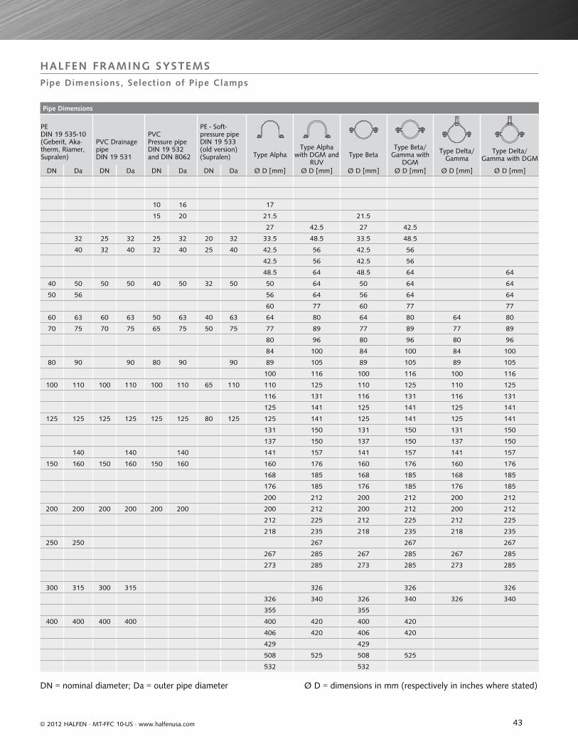
Pipe Dimensions
PEDIN 19 535-10 (Geberit, Aka-therm, Riamer, Supralen)
PVC Drainage pipe DIN 19 531
PVC Pressure pipe DIN 19 532 and DIN 8062
PE - Soft-pressure pipe DIN 19 533 (old version) (Supralen) Type Alpha
Type Alpha with DGM and
RUVType Beta
Type Beta/Gamma with
DGM
Type Delta/Gamma
Type Delta/Gamma with DGM
DN Da DN Da DN Da DN Da Ø D [mm] Ø D [mm] Ø D [mm] Ø D [mm] Ø D [mm] Ø D [mm]
10 16 17
15 20 21.5 21.5
27 42.5 27 42.5
32 25 32 25 32 20 32 33.5 48.5 33.5 48.5
40 32 40 32 40 25 40 42.5 56 42.5 56
42.5 56 42.5 56
48.5 64 48.5 64 64
40 50 50 50 40 50 32 50 50 64 50 64 64
50 56 56 64 56 64 64
60 77 60 77 77
60 63 60 63 50 63 40 63 64 80 64 80 64 80
70 75 70 75 65 75 50 75 77 89 77 89 77 89
80 96 80 96 80 96
84 100 84 100 84 100
80 90 90 80 90 90 89 105 89 105 89 105
100 116 100 116 100 116
100 110 100 110 100 110 65 110 110 125 110 125 110 125
116 131 116 131 116 131
125 141 125 141 125 141
125 125 125 125 125 125 80 125 125 141 125 141 125 141
131 150 131 150 131 150
137 150 137 150 137 150
140 140 140 141 157 141 157 141 157
150 160 150 160 150 160 160 176 160 176 160 176
168 185 168 185 168 185
176 185 176 185 176 185
200 212 200 212 200 212
200 200 200 200 200 200 200 212 200 212 200 212
212 225 212 225 212 225
218 235 218 235 218 235
250 250 267 267 267
267 285 267 285 267 285
273 285 273 285 273 285
300 315 300 315 326 326 326
326 340 326 340 326 340
355 355
400 400 400 400 400 420 400 420
406 420 406 420
429 429
508 525 508 525
532 532
HALFEN FRAMING SYSTEMSPipe Dimensions, Selection of Pipe Clamps
© 2012 HALFEN · MT-FFC 10-US · www.halfenusa.com
DN = nominal diameter; Da = outer pipe diameter Ø D = dimensions in mm (respectively in inches where stated)
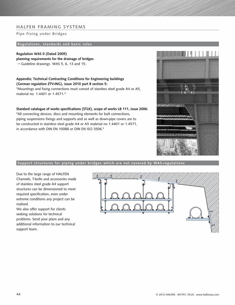
44
HALFEN FRAMING SYSTEMSPipe Fixing under Bridges
© 2012 HALFEN · MT-FFC 10-US · www.halfenusa.com
Regulation WAS 0 (Dated 2009) planning requirements for the drainage of bridges → Guideline drawings WAS 5, 6, 13 and 15.
Appendix; Technical Contracting Conditions for Engineering buildings (German regulation ZTV-ING), issue 2010 part 8 section 5:
Standard catalogue of works specifications (STLK), scope of works LB 111, issue 2006:
"Mountings and fixing connections must consist of stainless steel grade A4 or A5, material no. 1.4401 or 1.4571."
"All connecting devices, discs and mounting elements for bolt connections, piping suspensions fixings and supports and as well as down-pipe covers are to be constructed in stainless steel grade A4 or A5 material no 1.4401 or 1.4571, in accordance with DIN EN 10088 or DIN EN ISO 3506."
Due to the large range of HALFEN Channels, T-bolts and accessories made of stainless steel grade A4 support structures can be dimensioned to meet required specification, even under extreme conditions any project can be realised.We also offer support for clients seeking solutions for technical problems. Send your plans and any additional information to our technical support team.
Regulat ions, s tandards and bas ic ru les
Suppor t s t ructures for p ip ing under br idges which are not covered by WAS- regulat ions
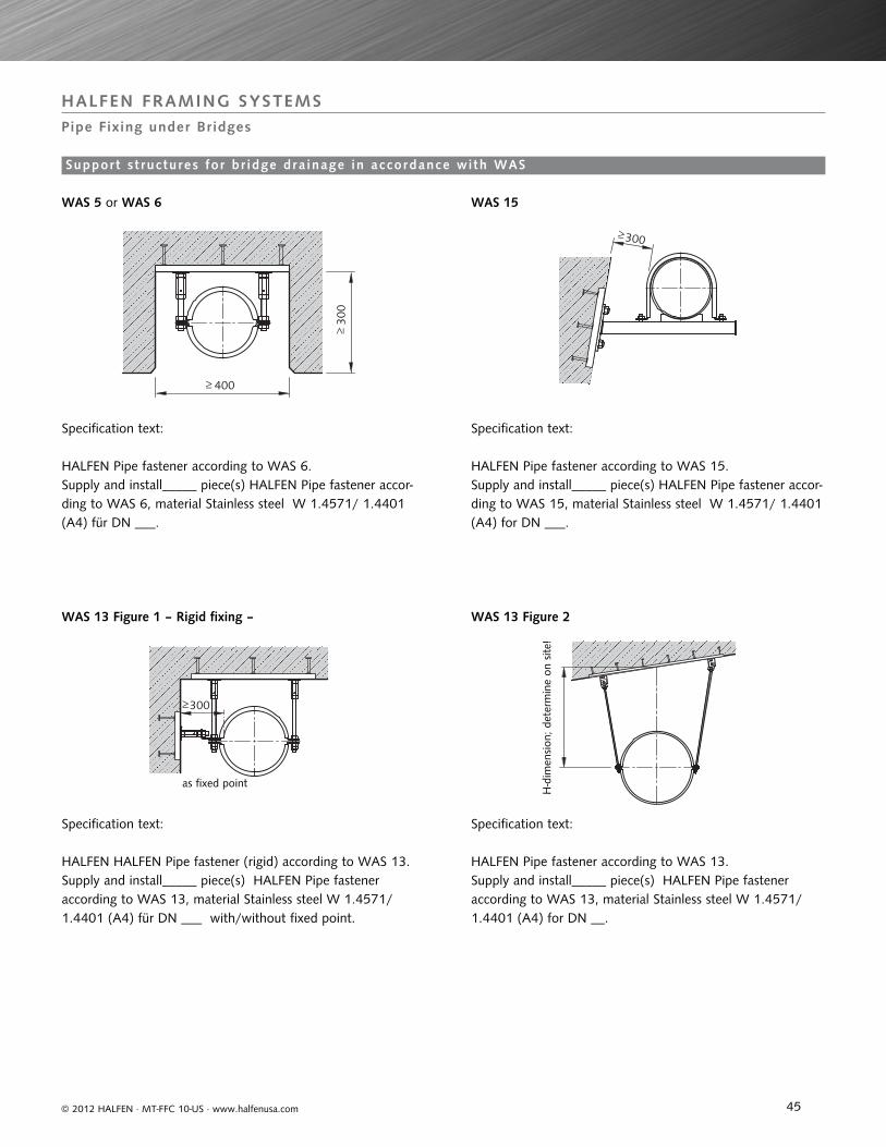
Support s t ructures for br idge dra inage in accordance with WAS
45
HALFEN FRAMING SYSTEMSPipe Fixing under Bridges
300
400
300
300
© 2012 HALFEN · MT-FFC 10-US · www.halfenusa.com
WAS 5 or WAS 6
WAS 13 Figure 1 – Rigid fixing – WAS 13 Figure 2
WAS 15
HALFEN Pipe fastener according to WAS 6. Supply and install_____ piece(s) HALFEN Pipe fastener accor-ding to WAS 6, material Stainless steel W 1.4571/ 1.4401 (A4) für DN ___.
Specification text:
Specification text:
as fixed point
H-d
imen
sion
; det
erm
ine
on s
ite!
Specification text:
Specification text:
HALFEN Pipe fastener according to WAS 15.Supply and install_____ piece(s) HALFEN Pipe fastener accor-ding to WAS 15, material Stainless steel W 1.4571/ 1.4401 (A4) for DN ___.
HALFEN HALFEN Pipe fastener (rigid) according to WAS 13.Supply and install_____ piece(s) HALFEN Pipe fastener according to WAS 13, material Stainless steel W 1.4571/ 1.4401 (A4) für DN ___ with/without fixed point.
HALFEN Pipe fastener according to WAS 13.Supply and install_____ piece(s) HALFEN Pipe fastener according to WAS 13, material Stainless steel W 1.4571/ 1.4401 (A4) for DN __.
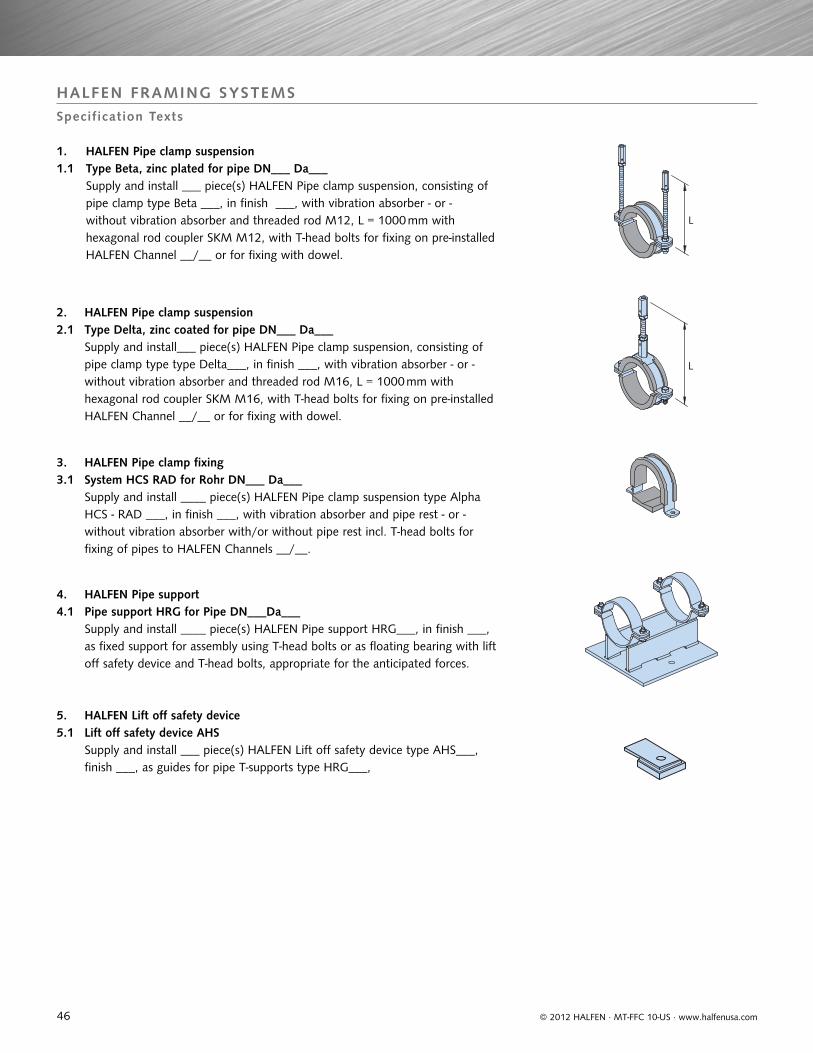
46
HALFEN FRAMING SYSTEMSSpecification Texts
L
L
© 2012 HALFEN · MT-FFC 10-US · www.halfenusa.com
2. HALFEN Pipe clamp suspension 2.1 Type Delta, zinc coated for pipe DN___ Da___ Supply and install___ piece(s) HALFEN Pipe clamp suspension, consisting of pipe clamp type type Delta___, in finish ___, with vibration absorber - or - without vibration absorber and threaded rod M16, L = 1000 mm with hexagonal rod coupler SKM M16, with T-head bolts for fixing on pre-installed HALFEN Channel __/__ or for fixing with dowel.
3. HALFEN Pipe clamp fixing 3.1 System HCS RAD for Rohr DN___ Da___ Supply and install ____ piece(s) HALFEN Pipe clamp suspension type Alpha HCS - RAD ___, in finish ___, with vibration absorber and pipe rest - or - without vibration absorber with/or without pipe rest incl. T-head bolts for fixing of pipes to HALFEN Channels __/__.
4. HALFEN Pipe support 4.1 Pipe support HRG for Pipe DN___Da___ Supply and install ____ piece(s) HALFEN Pipe support HRG___, in finish ___, as fixed support for assembly using T-head bolts or as floating bearing with lift off safety device and T-head bolts, appropriate for the anticipated forces.
5. HALFEN Lift off safety device5.1 Lift off safety device AHS Supply and install ___ piece(s) HALFEN Lift off safety device type AHS___, finish ___, as guides for pipe T-supports type HRG___,
1. HALFEN Pipe clamp suspension1.1 Type Beta, zinc plated for pipe DN___ Da___
Supply and install ___ piece(s) HALFEN Pipe clamp suspension, consisting of pipe clamp type Beta ___, in finish ___, with vibration absorber - or - without vibration absorber and threaded rod M12, L = 1000 mm with hexagonal rod coupler SKM M12, with T-head bolts for fixing on pre-installed HALFEN Channel __/__ or for fixing with dowel.
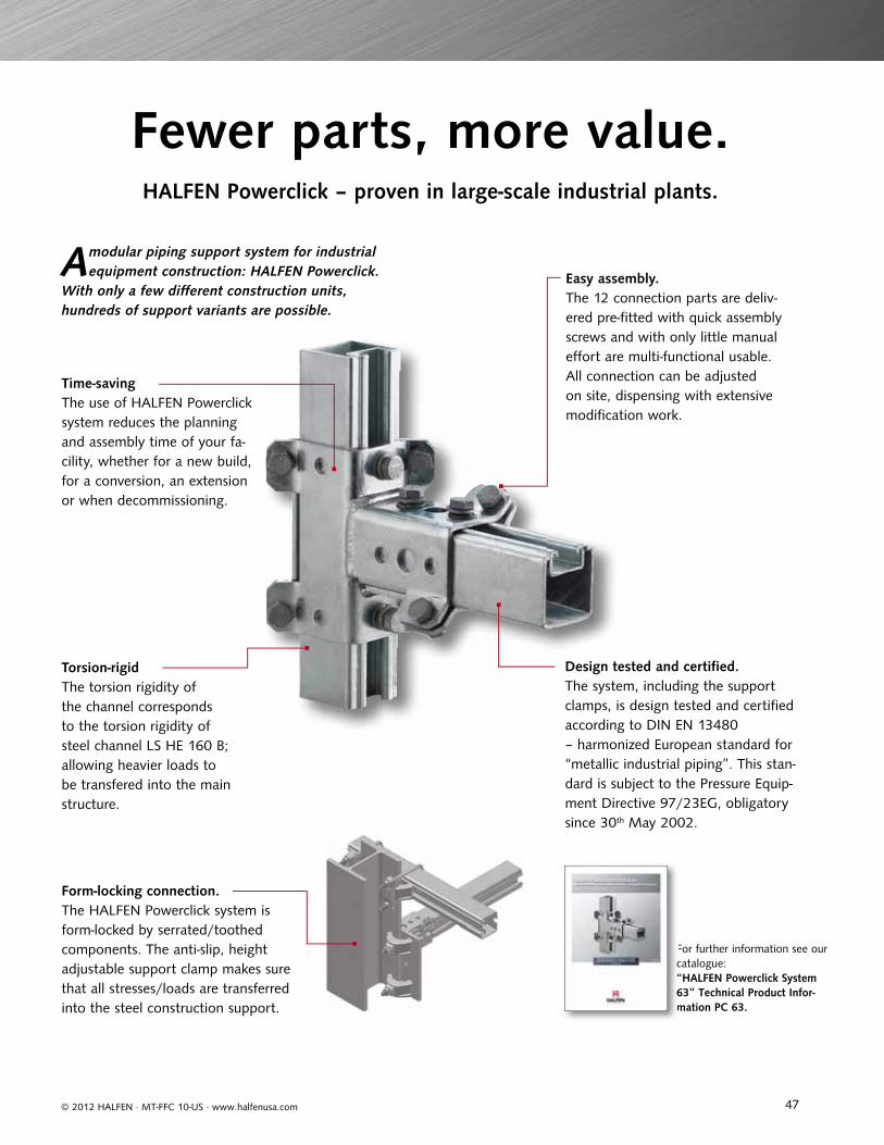
47© 2012 HALFEN · MT-FFC 10-US · www.halfenusa.com
Design tested and certifi ed. The system, including the support clamps, is design tested and certifi ed according to DIN EN 13480 – harmonized European standard for “metallic industrial piping”. This stan-dard is subject to the Pressure Equip-ment Directive 97/23EG, obligatory since 30th May 2002.
Fewer parts, more value.HALFEN Powerclick – proven in large-scale industrial plants.
A modular piping support system for industrial equipment construction: HALFEN Powerclick.
With only a few diff erent construction units, hundreds of support variants are possible.
Form-locking connection.The HALFEN Powerclick system is form-locked by serrated/toothed components. The anti-slip, height adjustable support clamp makes sure that all stresses/loads are transferred into the steel construction support.
Easy assembly.The 12 connection parts are deliv-ered pre-fi tted with quick assembly screws and with only little manual eff ort are multi-functional usable. All connection can be adjusted on site, dispensing with extensive modifi cation work.
Torsion-rigidThe torsion rigidity of the channel corresponds to the torsion rigidity of steel channel LS HE 160 B; allowing heavier loads to be transfered into the main structure.
Time-saving The use of HALFEN Powerclick system reduces the planning and assembly time of your fa-cility, whether for a new build, for a conversion, an extension or when decommissioning.
For further information see our catalogue:“HALFEN Powerclick System 63” Technical Product Infor-mation PC 63.
Fc“6m
M -
013
- US
- 06/
11
04/
12©
201
2 H
ALF
EN G
mbH
, Ger
man
yap
plie
s al
so t
o co
pyin
g in
ext
ract
s.
CONTACT HALFEN WORLDWIDE
www.halfen.com
HALFEN has a g lobal network of Subs id iary Companies to ass is t you. The main contact in format ion for North Amer ica , Europe and As ia i s prov ided be low. For a fu l l l i s t of of f i ces p lease v is i t www.hal fen.com
HALFEN GmbH shall not accept liability for the accuracy of the information in this publication or for any printing errors.
HALFEN is also represented by distributors in Argentina, Australia, Azerbaijan, Belarus, Brazil, Bulgaria, Chile, Colombia, Croatia/Bosnia-Herzegovina/FYROM/Montenegro, Cyprus, Estonia, Greece, Hong Kong, Hungary, Indonesia, Ireland, Israel, Jordan, Kingdom of Saudi-Arabia, Latvia, Lebanon, Lithuania, Luxembourg, Malaysia, Malta, Mexico, New Zealand, Peru, Philippines, Republic of Kazakhstan, Romania, Russia, Serbia, Singapore, Slovenia, South Korea, Taiwan/ROC, Thailand, Turkey, Ukraine, United Arab Emirates, Uruguay, Vietnam
USA & Mexico HALFEN USA Inc.8521 F.M. 1976Converse, TX 78109
Phone: +1 800.423.9140E-Mail: [email protected]: www.halfenusa.com
Fax: +1 888.277.1695
Fax: +86 - 10 5907 3218
Canada
China
UCC Industries International (Distributor)Units 12 & 13895 Sandy Beach RoadPickering, Ontario, L1W 3N7
Provinces of British Columbia and Alberta: Please contact HALFEN USA Inc.
HALFEN Construction Accessories Distribution Co.Ltd.Room 601 Tower D, Vantone CentreNo.A6 Chao Yang Men Wai StreetChaoyang DistrictBeijing · P.R. China 100020
Phone: +1 905.831.7724E-Mail: [email protected]: www.ucci.ca
Phone: +86 - 10 5907 3200E-Mail: [email protected]: www.halfen.cn
Fax: +1 905.831.5872
Fax: +91 22.4202.4001
Fax: +49 2173 970-123
India
Germany
CRH India Management Services Pvt. Ltd.73-C, 3 North Avenue, Maker Maxity, Bandra-Kurla Complex, Bandra (East), Mumbai 400 051
HALFEN GmbHLiebigstrasse 14 40764 Langenfeld
Phone: +91 22.4202.4000E-Mail: [email protected]: www.halfen.in
Phone: +49 2173 970-0 E-Mail: [email protected]: www.halfen.de