HabiTEQ Installers Catalogue Final Version
11
GE Consumer & Industrial Power Protection GE imagination at work HabiTEQ TM Flexible home automation for energy efficiency, safety and comfort
-
Upload
sumer-land -
Category
Documents
-
view
225 -
download
0
Transcript of HabiTEQ Installers Catalogue Final Version

8/13/2019 HabiTEQ Installers Catalogue Final Version
http://slidepdf.com/reader/full/habiteq-installers-catalogue-final-version 1/11
GE Consumer & IndustrialPower Protection
GE imagination at work
HabiTEQTM
Flexible home automation
for energy efficiency, safetyand comfort

8/13/2019 HabiTEQ Installers Catalogue Final Version
http://slidepdf.com/reader/full/habiteq-installers-catalogue-final-version 2/11

8/13/2019 HabiTEQ Installers Catalogue Final Version
http://slidepdf.com/reader/full/habiteq-installers-catalogue-final-version 3/11
5
INP08/16Input module
INP08/230Input module
HabiTEQTM HabiTEQTM
4
• Fast & Flexible two wire Bus system• Quick & Easy configuration• “Plug&Play” operation!
INP08 230Input module
• “P ug&P ay” operat on!
ANR04Analogue dimmer modulefor fluorescent tubes
DIM 04/500immer module
00VA
DIM04/300Dimmer module
300VA
SMS01Mobile interface module
CTL16 up to 256Controller
REL044 Relay module
Home automation modules
ROL022 Shutter relay module
REL088 Relay module
Separate cable compartment (enclosure types C-D-E-F)Enclosure shown is type C7. (See p.10)
ETH02Ethernet module
ANA04Analogue dimmer module

8/13/2019 HabiTEQ Installers Catalogue Final Version
http://slidepdf.com/reader/full/habiteq-installers-catalogue-final-version 4/11
7
HabiTEQTM HabiTEQTM
6
• Quick & Easy installation
Protection equipment
MCB’s forline protection
Surge protection
Potential free and analogue inputsConnections from push-buttons,magnetic contacts and externaldetectors to input module.
Controlled outputs
Contactors forcontrolled socket-outlets
Overvoltageprotection
RCD’s for people protection
Screwless terminalsfor quick connection
D
R
M
D
R
M
Bus connection
Motor
Dimmer
Relay
Conventionalcabled andcontrolledsocket-outlets
8/13/2019 HabiTEQ Installers Catalogue Final Version
http://slidepdf.com/reader/full/habiteq-installers-catalogue-final-version 5/11
8
HabiTEQTM HabiTEQTM
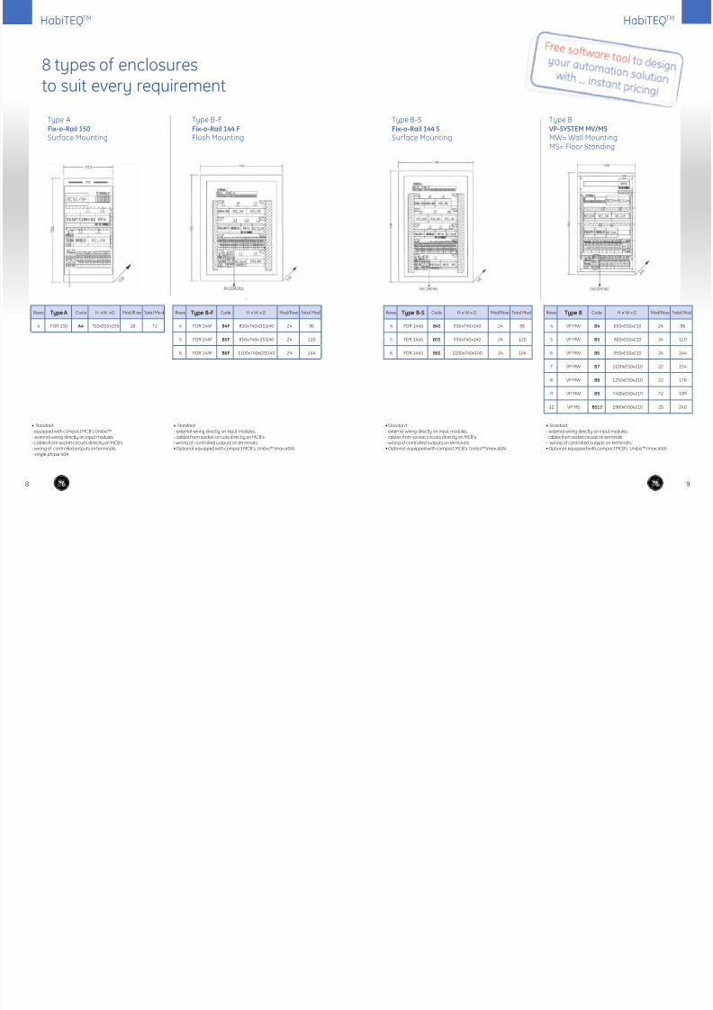
8 types of enclosuresto suit every requirement
Type B-FFix-o-Rail 144 F
Flush Mounting
Type B-SFix-o-Rail 144 S
Surface Mounting
Type BVP-SYSTEM MV/MS
MW= Wall MountingMS= Floor Standing
Type AFix-o-Rail 150
Surface Mounting
Rows Type A Cod e H x W x D Mod /R ow Tota l Mo d
4 FOR 150 A4 750x355x150 18 72
Rows Type B-F Code H x W x D Mod/Row Total Mod
4 FOR 144F B4F 800x740x(35)140 24 96
5 FOR 144F B5F 950x740x(35)140 24 120
6 FOR 144F B6F 1100x740x(35)140 24 144
Rows Type B-S Code H x W x D Mod/Row Total Mod
4 FOR 144S B4S 800x740x140 24 96
5 FOR 144S B5S 950x740x140 24 120
6 FOR 144S B6S 1100x740x140 24 144
Rows Type B Code H x W x D Mod/Row Total Mod
4 VP MW B4 650x550x210 24 96
5 VP MW B5 800x550x210 24 120
6 VP MW B6 950x550x210 24 144
7 VP MW B7 1100x550x210 22 154
8 VP MW B8 1250x550x210 22 176
9 VP MW B9 1400x550x210 22 198
12 VP MS BS12 1980x550x210 20 240
• Standard:- equipped with compact MCB’s Unibis™. - external wiring directly on input modules.- cables from socket circuits directly on MCB’s- wiring of controlled outputs on terminals.- single phase 40A
• Standard:- external wiring directly on input modules.- cables from socket circuits directly on MCB’s- wiring of controlled outputs on terminals.• Optional: equipped with compact MCB’s Unibis™ (max.40A).
• Standard:- external wiring directly on input modules.- cables from socket circuits directly on MCB’s- wiring of controlled outputs on terminals.• Optional: equipped with compact MCB’s Unibis™ (max.40A).
• Standard:- external wiring directly on input modules.- cables from socket circuits on terminals- wiring of controlled outputs on terminals.• Optional: equipped with compact MCB’s Unibis™ (max.40A).
9

8/13/2019 HabiTEQ Installers Catalogue Final Version
http://slidepdf.com/reader/full/habiteq-installers-catalogue-final-version 6/11
10
HabiTEQTM HabiTEQTM
Type CVP-SYSTEM MW/MS
Type DVP-SYSTEM MW/MS
Rows Type C Code H x W x D Mod/Row Total Mod
5 VP MW C5 800x800x210 22 110
6 VP MW C6 950x800x210 22 132
7 VP MW C7 1100x800x210 22 154
8 VP MW C8 1250x800x210 22 176
9 VP MW C9 1400x800x210 22 198
12 VP MS CS12 1980x800x210 22 264
Rows Type D Code H x W x D Mod/Row Total Mod
5 VP MW D5 800x1050x210 34 170
6 VP MW D6 950x1050x210 34 204
7 VP MW D7 1100x1050x210 34 238
8 VP MW D8 1250x1050x210 34 272
9 VP MW D9 1400x1050x210 34 306
12 VP MS DS12 1980x1050x210 34 408
• Standard:- separate cable compartment (in- and outgoing cables)- cables from socket circuits on terminals.- wiring of controlled outputs on terminals.- wiring of inputs on terminals.• Optional: equipped with compact MCB’s Unibis™ (max.40A).
• Standard:- separate cable compartment (i n- and outgoing cables)- cables from socket circuits on terminals.- wiring of controlled outputs on terminals.- wiring of inputs on terminals.• Optional: equipped with compact MCB’s Unibis™ (max.40A).
11
Type EVP-SYSTEM MW
Type FQuixtra™ 630
Rows Type E Code H x W x D Mod/Row Total Mod
5 VP MW E5 800 x1300x210 38 190
6 VP MW E6 950 x1300x210 38 228
7 VP MW E7 1250x1300x210 38 266
8 VP MW E8 1400x1300x210 38 304
9 VP MW E9 1980x1300x210 38 342
• Standard:- separate cable compartment (in- and outgoing cables)- cables from socket circuits on terminals- wiring of controlled outputs on terminals.- wiring of inputs on terminals.• Optional: equipped with compact MCB’s Unibis™ (max.40A).
• Standard:-separate cable compartment (in- and outgoing cables)- cables from socket circuits on terminals- wiring of controlled outputs on terminals.- wiring of inputs on terminals.• Optional: - equipped with compact MCB’s Unibis™ (max.40A).
- plain door (modules compartiment)
Rows Type Code H x W x D Mod/Row Total Mod
5 QuiXtra 630 F5 750x1240x250 36 180
6 QuiXtra 630 F6 9 00 x1 24 0x2 50 3 6 2 16
7 QuiXtra 630 F7 1 05 0x 12 40 x2 50 3 6 2 52
8 QuiXtra 630 F8 1200x1240x250 36 288
9 QuiXtra 630 F9 1 60 0x 12 40 x2 50 3 6 3 24
10 QuiXtra 630 F10 1750x1240x250 36 360
12 QuiXtra 630 F12 2050x1240x250 36 432
8/13/2019 HabiTEQ Installers Catalogue Final Version
http://slidepdf.com/reader/full/habiteq-installers-catalogue-final-version 7/11
13
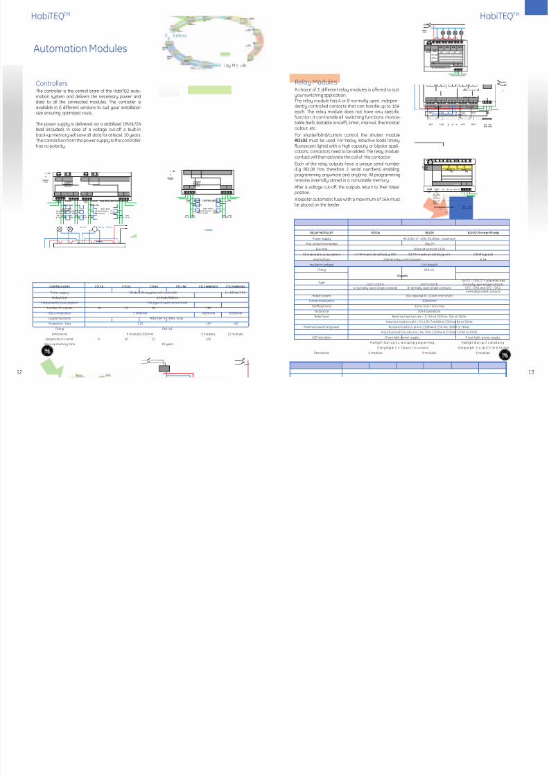
Relay ModulesA choice of 3 different relay modules is offered to suityour switching application.The relay module has 4 or 8 normally open, indepen-dently controlled contacts that can handle up to 16Aeach. The relay module does not have any specificfunction. It can handle all switching functions: monos-table (bell), bistable (on/off), timer, interval, thermostatoutput, etc.
For shutter/blind/curtain control, the shutter moduleROL02 must be used. For heavy inductive loads (manyfluorescent lights) with a high capacity or bipolar appli-cations, contactors need to be added. The relay modulecontact will then activate the coil of the contactor.
Each of the relay outputs have a unique serial number(E.g REL08 has therefore 2 serial numbers) enablingprogramming anywhere and anytime. All programmingremains internally stored in a nonvolatile memory.
After a voltage cut-off, the outputs return to their latestposition.
A bipolar automatic fuse with a maximum of 16A mustbe placed on the feeder.
RELAY MODULES REL04 REL08 ROL02 (Shutter/Blinds)
Power supply AC 230V +/- 10%, 50..60Hz - maximum
Max. protection needed 16A/2P
Bus load 10mA at nominal 13,8V
Ch ar act er ist ic co nsu mpt io n 4 .7 VA m ax im um (al l re la ys ON) 9 .6 VA m ax im um (al l re la ys on ) 2 .8 VA (t yp ic al )
Internal fuse 100mA (relay control power) 6.3A
Insulation voltage 3 kV (tested)
Fitting DIN rail
Ouputs
TypeOUT1–OUT4:
4 normally open single contactsOUT1–OUT8:
8 normally open single contacts
UP1/2 – DN1/2: 4 potential-freenormally open single contacts
UP1 – DN1 and UP2 – DN2:internally locked contacts
Rated current 16A (resistive @ 230Vac and 30Vdc)
Contact resistance 100mOhm
Set/Reset time 15ms max / 5ms max
Endurance 20mil operations
Rated load Resistive load (cos phi = 1) 16A at 230Vac; 16A at 30Vdc
Inductive load (cos phi = 0,4; L/R=7ms) 8A at 230Vac; 8A at 30Vdc
Maximum switching power Resistive load (cos phi=1) 2300VA at 230 Vac 300W at 30Vdc
Inductive load (cos phi=0,4; L/R=7ms) 1150VA at 230Vac 150W at 30Vdc
LED indication Green light: power supply Green light: power supply
Red l ig ht : Start-u p 2 s , an d du ri ng p rogrammi ng Red li gh t: Start- up 2 s, an d d ur in g
O ra ng e l ig ht 1- X : Ou tp ut 1 to x a ct iv e O ra ng e l ig ht 1- 4: Up 1/ 2– Dn 1/ 2 a ct iv e
Dimensions 6 modules 9 modules 6 modules
12
HabiTEQTMHabiTEQTM
Automation Modules
CONTROLLERS CTL16 CTL32 CTL64 CTL256 CTL256BEX02 CTL256BEX04
Power supply 18Vdc/3,9A (supplied with controller) 2 x 18Vdc/3,9A
Output bus 13,8Vdc/500mA
Characteristic consumption 2VA typical ( with no bus load)
Number of outputs 16 32 64 388
Bus connections 2 (500mA) 4(500mA) 6(500mA)
Logical functions AND/OR/ IF.. THEN.. ELSE..
Protection - fuse 1 AT 1AT 1AT
Fitting DIN rail
Dimensions 6 modules (105mm) 9 modules 12 modules
Sequences or scenes 8 16 32 128
Back-up memory time 10 years
230VAC50Hz
L 16A
N
FUSE1AT OUT1
RELAYMODULE REL04 SERIAL
50Hz
230V
Each contact:Max. switchedcurrent:16A at 230Vac
Max. switchedPower:2000VA
1......................................................................
.....................................................................
.....................................................................
.....................................................................
2.
4.
3.
Ph N
O UT 2 O UT 3 O UT 4
BUS
A 1 A 2 A 1 A 2
BUS
18Vdc/1.4A
CONTROLLERCTL 16 ... .......256
BUS2A1 A2A1 A2
BUS2BUS1
FUSE1 AT
POWER
A1 A2BUS1
BUS1 - BUS2:
Nominal tension : 12VdcMax. current : 500mA
Modules
18Vdc/3,9A
POWERSUPPLY
A1 A2
230VAC50Hz
L 16A
N
M
MM
L 16A
N
1.
OUT1 OUT2 N NN OUT3 OUT4
....................................
5. .................................... 6.
2.
.................................... 7. ....................................
3. .................................... 4. ....................................
8. ....................................
RELAYMODULE REL08
Each contact: max. switched current:16A at 230Vac
SERIAL
.....................................
SERIAL
50Hz230V
NC N
BUSA1A2
BUSA1A2
OUT5 OUT6 N N N OUT7 OUT8
230VAC50Hz
L 16A
N
M1 M2
Each contact:Max. switchedcurrent:16A at 230Vac
Max. switchedPower:2000VA
1......................................................................
.....................................................................
.....................................................................
.....................................................................
2.
4.
3.
UP/DOWN ROL02 SERIALBUSA 1 A 2 A 1 A 2
BUS
FUSE1AT 50Hz
230VPh Ph UP1 Ph UP2NC DN1 NC DN2N
A1 A2BUS2
A1 A2BUS2
A1 A2
Modules Modules Modules Modules
230VAC50Hz
L 16A
N
18Vdc/3,9A
POWERSUPPLY
POWER CONTROLLERCTL256-BEX02FUSE1 AT
FUSE1.2 AT
POWER
18Vdc/1.4A
BUS1 - BUS2:
18Vdc/1.4A
BUS1A1 A2
BUS1A1 A2
B US 1 B U S1A1 A2
BUS2A1 A2
BUS2A1 A2
Nominal tension : 12VdcMax. current : 500mA
BUS1 - BUS2:Nominal tension : 12VdcMax. current : 500mA
ControllersThe controller is the central brain of the HabiTEQ auto-mation system and delivers the necessary power anddata to all the connected modules. The controller isavailable in 6 different versions to suit your installationsize ensuring optimized costs.
The power supply is delivered via a stabilized 18Vdc/2Alead (included). In case of a voltage cut-off a built-in
back-up memory will save all data for at least 10 years.The connection from the power supply to the controllerhas no polarity.
Controllers
Relay Modules
trollers
lay Mo ule

8/13/2019 HabiTEQ Installers Catalogue Final Version
http://slidepdf.com/reader/full/habiteq-installers-catalogue-final-version 8/11
Dimmer ModulesChoices of 4 different dimmer modules are offeredto suit a variety of dimming applications. The mod-ules are controlled and programmable throughthe bus operating digitally with 8-bit precision. Anoptical separation between the inputs and outputs guar-antees safe operation.Multiple possibilities for dimmer control
1. One-button dimmer - Possible to reduce thenumber of control buttons.
2. Two-button dimmer - + and a – button enhancingthe operating comfort.
When a pressed button is kept in, the transit time fromzero to maximum is 5.1s. A short pulse (< 0.3s) will takethe dimmer to zero or to the maximum value in 2.5s.
The maximum value can be adjusted from 20 to 100%.The lighting can also be dimmed automatically aftera set time of 1s to 255min. ideal for bedrooms… If thedimmers are controlled by a sequence the rise time andfall time can be adjusted independently between 0.3sand 20min. Each module has a unique serial numberenabling programming anywhere and anytime. After avoltage cut-off the outputs return to their latest position.
DIMMERS DIM04/300 DIM04/500 ANA04 ANR04
Forward phase dimmer modules Analogue dimmer modules
Power supply AC 230V, 50Hz - maximum (60Hz on request)
Max. protection needed 10A/2P 16A/2P
Bus load 10mA at 13,8V
Characteristic consumption 2.8VA 2.5VA 1.5VA
Internal fuse 6.3A 4 X 4AF NA -
Fitting DIN rail
Insulation voltage 3kV
TypeOUT1 – OUT4 :
Dimmable outputs300Va/channel
OUT1 – OUT4 :Dimmable outputs
500VA/channel
OUT1 – OUT4 :Analogue outputs,0-10V or 1-10V /
channel
OUT1 – OUT4 :Analogue outputs, 0-10V or 1-10V
SW1 – SW4 :4 normally open single contacts
Maximum loadIncandescent load 300VA
at 230VACIncandescent load 500VAat
230VAC10mA
Minimum load 30% of maximum output - -
LED indication Green light : power supply
Red light : Start-up 2 s, and during programming- - - Orange light 1-4 : Output 1 to 4 active
DIP switches - - 4 internal DIPswitches to select the outputs as 0-10V or 1-10V
Rated current - - - 16A
Contact resistance - - - 100mOhm
Endurance - - - 20mil operations
Rated load - - - Resistive load (cos phi = 1) 16A at 230Vac; 16A at 30VDC
- - - Inductiveload(cosphi=0,4;L/R=7ms)8Aat 230Vac;8Aat 30VDC
Maximum switching power - - - Resistiveload(cos phi=1)2300VAat230 VAC300Wat30VDC
- - - Inductiveload (cosphi=0,4; L/R=7ms)1150VAat 230VAC150Wat 30VDC
Dimensions 6 modules 9 modules 6 modules 9 modules
1514
HabiTEQTMHabiTEQTM
230VAC50Hz
L 16A
N
OUT1 OUT2 OUT3 OUT4 SW1 SW2
SW3 SW4
50Hz
Each output:0-10Vdc or1-10vdcMaxCurrent5ma
Each contact:max 16A/250Vac
230VPh N
DIMMERANR04 BUSA1A2
BUSA1A2
1.................................................................................................
................................................................................................
................................................................................................
................................................................................................
2.
4.
3.
Dimmableballasts
230VAC50Hz
L 16A
N
OUT4OUT3OUT2OUT1
DIMMERANA04BUS
A1A2
BUS
A1A2
Dimmableballasts
50Hz
Each output:0-10Vdc or1-10vdcMaxCurrent5ma
230VPh N
1..........................................................................................
2..........................................................................................
3..........................................................................................
4..........................................................................................
230VAC50Hz
L 10A
N
OUT150Hz
DIMMERD IM04/300
FUSE
Cach outputResistiveload
orinductiveload
Max. switchedPower:
300VA/230Vac
6.3AF
230V N
1..................................................................................
.................................................................................
.................................................................................
.................................................................................
2.
4.
3.
Ph N
OUT2 OUT3 OUT4
BUSA1A2
BUSA1A2
N N N
2AF 2AF 2AF 2AF
230VAC50Hz
L 16A
N
OUT150Hz
DIMMERDIM04/500
FUSE
Cach outputResistive load
orinductive load
Max. switchedPower:
300VA/230Vac
6.3AF230V
N
1..................................................................................
.................................................................................
.................................................................................
.................................................................................
2.
4.
3.
Ph N
OUT2 OUT3 OUT4
BUSA1A2
BUSA1A2
N N N
Analogue dimmer ANA04Suitable for controlling four analog dimmersoperating with input voltages of 0-10V or 1-10V. Thismodule can be used for dimming very large capacities.There are four internal DIPswitches. These can be usedto set each output to 0-10V or 1- 10V. It must be notedthat the control voltages must not be connected to themains. The negative terminals are internally linked. Thecontrol and programming are done through the 2-wirebus, one or two button dimmer control.
Dimmer module DIM04/300-500Module for a DIN-rail, suitable for dimming 4 loads of 40-300/500VA. The phase offset of each load is measuredseparately thus allowing the use of resistive (light bulbs)and inductive loads (conventional transformers). Electronictransformers can be used if they operate according to thephase leading principle. For the 300VA dimmer modulesa 2AF type fuse must be provided per output. Ensureadequate ventilation in the fuse box.On the 500VA dimmer modules,each dimmer output is fusedinternally with a 4AF fuse. A bipolar automatic fuse of amaximum of 16A must be placed on the mains power.
Note an additional filter module will be supplied with
300/500Va dimmers
Analogue dimmer ANR04Each analog output controls a relay contact, whichreleases when the output is on 0. This contact candisrupt the mains voltage so that the fluorescent lampsgo out completely. There are four internal DIP switches.These can be used to set each output to 0-10V or 1-10V.It must be noted that the control voltages must not beconnected to the mains. The negative terminals areinternally linked. The control and programming is donethrough the 2-wire bus, one or two button dimmercontrol.
Dimmer Modules
8/13/2019 HabiTEQ Installers Catalogue Final Version
http://slidepdf.com/reader/full/habiteq-installers-catalogue-final-version 9/11
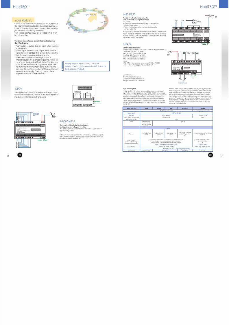
There are 8 or 16 optically insulated inputs.Each input needs a voltage to be active.This can be 12Vac/dc if connected between B and C (consumptionapproximately 10mA)
If there are inputs with potential-free contacts they can be connectedto the module via 12Vac. The required voltage is provided on the topand bottom sides of the module.
Led indication :Green light (right): bus powerGreen light (middle): mains powerRed light: data transfer + error LED
Product description
Module for DIN-rail, suitable for controlling four analogue inputsignals. The input signals can be four Pt100 - Pt1000 temperaturesensors or four analog input signals 0-10V. The temperature sensorsare to be connected to terminals PT1 till PT4. One can use a fourwire connection or a two wire connection. When using a two wireconnection terminals A-B and C-D should be short-circuited. Inputterminals ANA1 till ANA4 are used for importing any analog signalfrom 0-10V.
Remark: There is no possibility to have simultaneously a tempera-ture reading at PT1 and an analogue signal on ANA1. If PT1 is usedANA1 is no longer available and vice versa. Although a combina-tion of for instance a PT1 and an ANA2 is possible. Each modulehas a unique serial number enabling programming anywhere andanytime. All programming remains internally stored in a nonvolatilememory. After a voltage cut-off, the outputs return to their latestposition. A bipolar automatic fuse of a maximum of 16A must beplaced on the mains power.
INPUT MODULES INP04 INP08 INP16 INP08/230 INPA04
Digital input module analogue input module
Power supply 230Vac/50..60Hz
Bus load 20mA at 13.8V 10mA at 13.8V
Characteristic consumption 2.3VA@230Vac 2.8VA
Insulation voltage 3kVFitting Typically inside
conventionalswitch enclosure
on wall
DIN rail
Inputs
Number4 potential-free
inputs"8 potential-free
inputs16 potential-free
inputs
8 (12Vac/dc or 230Vacselectable by connec-
tion)
4 analogue inputs or 4 anologueoutputs
Input function(Configurable through
software serial manager)
Pusht button = button that is open when inactive (e.g. doorbell).Normal open = contact that is open when inactive.
Normal closed = contact that is closed when inactive.Switch = single-pole conventional switch.
Can be configured by SW :-1. PT100,PT1000
or2. 0-10V input
LED indication Green light : power supply Green light : power supply.
Red light : Start-up 2 s, and during programming
Dimensions 32x37x12mm 6 modules 9 modules 6 modules
1716
INP04This module can be used to interface with any conven-tional switch to the bus. The size of the module permitsinstallation within the switch enclosure.
INP08/INP16
There are 8 optically insulated inputs.Each input needs a voltage to be active.This can be:• 12Vac/dc if connected between B and C (consumption
approximately 10mA)• 230Vac if connected between A and C (consumption
approximately 1W)
• Orange LED lights positioned near inputs 1-8 indicate if input is active.
If there are inputs with potential-free contacts they can be connectedto the module via 12Vac. The required voltage is provided on the topand bottom sides of the module.
INP08/230
C I N1 IN2 IN 3 IN 4 IN 5 IN 6 IN 7 IN 8 C ANA1 ANA2 ANA3
IN1..IN16: potentialfreeOptional:ANA1..ANA8: analogueIN 0-10VC=commonNC=Not connected
OnlyIN1toIN8operationalforINP08
16AL
N
230VAC50Hz
ANA4
I N9 I N1 0 I N 11 I N1 2 I N1 3 I N 1 4 I N 1 5 I N 1 6 A NA 5 A NA 6 A NA 7 ANA8
BUS BUS
A 1 A 2 A 1 A 2C C
230V
50HZ
Ph NC N
INPUTINP 08/16
230VA50Hz
L 16A
N
BUSA2A1 A1
BUSA2
230V/1.5VAOutputmax100ma1A 1B 1C
INPUTMODULE INP08/230
INPUT:
XA-XB=max 230Vac/1W
XB-XC=mas12Vac/dc/10ma
NC= not connected
23 0VA C 2 30 VAC12V
2 A 2 B 2 C 3 A 3 B 3 C 4 A 4 B 4 C
5 A 5 B 5 C 6 A 6 B 6 C 7 A 7 B 7 C 8 A 8 B 8 C
P h N C NNC12Vac
Outputmax100maNC12Vac
BUS2
A1 A2
BUS2
A1 A2
230VAC50Hz
P†100P†1000
or
L 16A
N
A B C D A B C D A B C DFUSE0,5A
Ph N230 V PT1 P T2 PT3
ANA1-ANA4Analogue 0-10V
PTI-PT4PT100... orPT100
INPUTAN104
P T1 A NA 1
+ _ A B C D
ANA2
+ _ ANA3
+ _ ANA4
+ _
+ _
AB
CD
P†100P†1000
10V DCUseonlyoneata time,either12Vac or230Vac
INPUTMODULE INP04
C V+ L1 L2 L3 L4 B U S
INPUTCONTACTSPOTENTIAL FREE LEDS
IN2IN1 IN3 I N4
General specifications :· Power supply : 230Vac +-10%, 50 Hz - maximum protection 6A/2P· Insulation voltage : 3 kV tested· Characteristic consumption : 2,8VA· Bus load : 10mA at nominal 13,8V
· Internal fuse : 500mA si ngle-phase· Max installation altitude : 2.000m
Inputs :· PT1 – PT4 : 4 temperature sensors type Pt100 or Pt1000ANA1 – ANA4 : 4 analogue input signals 0-10V
INPA04
Input ModulesChoice of five different input modules are available inthe HabiTEQ to connect external contacts such as so-lar/wind detector, movement detector, door switches,push-buttons and analogue sensors.8/16 optical isolated inputs are provided, which mustbe potential-free.
The input contacts can be selected and set usingthe PC software:
• Push-button = button that is open when inactive(e.g. doorbell)
• Normal open = contact that is open when inactive• Normal closed = contact that is closed when inactive• Switch = single-pole conventional switch.
The maximum length of each input is 200 m.The cable type is irrelevant as long as the 2 wires areeach 1mm2. (Contact load 1mA) Each of the 4 inputshas a unique serial number. (E.g. So INP08 has 2 se-rial numbers and INP16 has 4 serial numbers). Thecommon (1st connector on the right top and bottom)is connected internally. One may connect thesetogether with other ‘INP16’ modules.
! Always use potential-free contacts!never connect or disconnect modules whilethe bus is energized!
Input Modules
HabiTEQTMHabiTEQTM

8/13/2019 HabiTEQ Installers Catalogue Final Version
http://slidepdf.com/reader/full/habiteq-installers-catalogue-final-version 10/11
Communication
Interfaces
1918
DLL to communicate with all features of the system,is available as freeware:• The software when installed on the PC and connected
to the HabiTEQ allows performing the following:• Initializing the controller (assign outputs, switching
behavior, timer, parameters, shutters, dimmers, etc.)• Addressing of input and output modules• Creating sequences• Setting switching times• Constructing logical functions
SER02
BUS
10/100 BASE-TETHERNET
MACaddress
TCP/IP BUSA1 A2 A1 A2
BUS
ETHERNETINTERFACE ETH02230V50Hz
Ph N
230VAC50Hz
L 16A
N
MOBILE INTERFACE SMS01
SMS MODULE
Power supply AC 230V, 50..60Hz - maximum
Power guard connection Power guard inputs: Connection I1 – C : 230Vac – max 1VA Connection I2 – C : 12Vac – max 1VA
Bus load 10mA at 13.8Vdc
Characteristic consumption 2.3VA
Internal fuse 1AT
Insulation voltage 3kV
Ou tp uts U p t o 9 6 o utp ut s ( in cl udi ng se qu en ce s) c an be ac tiv at ed or vi ew ed
Access and agenda phone numbers Max. 8 phone numbers (+1 emergency number) can get access to the system
Control possibilities SMS texts can have different defined texts for different users and different status definition
Alarm messages Max.16 alarm messages can be sent to all numbers
Warning power down to all numbers if battery is connected
Pincode possibility of enable / disable
SIM card Not included
Antenna In built antenna on top and optional external antenna
Band width Tri-band
Dimensions 6 modules
General specifications for all automation modulesO pe ra ting t em pe ra tu re 1 0 t o 5 0º C w it ho ut co nd en sa tion
S to ra ge t em pe ra tu re - 10 t o 6 0º C w it ho ut c on de nsat io n
Maximum humidity 93%, no moisture condensation
Protection degree IP20, EN 60529
Fitting DIN rail to DIN EN 50022
230VAC50Hz
L 16A
N
SMSMO DULE SMS01FUSE1 AT
PH
230Vac
Powercontrol:
12Vac
230Vac
PowerFail
Useonlyoneatatime, either
12Vac or230Vac.
11-C=230Vac12-C=12Vac
2.3VA
N
BUS11 12 CA1 A2 A1 A2
BUS
signal
Mobile Interface ModuleThe SMS01 is a DIN mounted module that can be installedwithin the HabiTEQ. The power supply is 230Vac. If themodule must work when power drops, a UPS or inter-nal rechargeable battery (Li-Ion) needs to be installedoptionally. A connection (230V or 12V) is available inorder to be able to send a message when the powerdrops.
The SIM card must be inserted on top of the moduleinto the SIM card reader. If the module is mounted in ametal distribution box or on a place with bad networkcoverage (cellar, concrete....) it is recommended to addan optional antenna.
Features:• Maximum 8 phone numbers (+1 emergency number)
can get access to the system• View and control outputs: max 96 channels (sequences
included) can be activated - Confirmation to selectable numbers - Comparison SMS texts with more than 1 user defined
texts e.g. “KITCHEN ON” or “KTC ON” - Different value definitions (e.g. ON- OFF - 0 - 1 - 50%...)• Alarm messages: - Maximum 16 different alarm messages (e.g. “burglar
alarm”, “fire”,” power down etc.) can be sent to up to8 + 1 phone numbers with intervals selectable from1min…. 10min.) and repeat rate 1-5 for each SMScan be set.
- Stop sending alarm texts when “SMS - STOP”message is received.
- Warning power down to all Numbers
Communication InterfacesCommunication can be established through PC viaan Ethernet connection or through a serial adapter forprogramming the system. Further control of the HabiTEQcan also be done through a mobile phone using basicpre-configured SMS messages.
Ethernet/WEB interfaceThe Ethernet interface module for DIN rail allows theHabiTEQ system to communicate with a PC or network.The module can be connected to the bus in any loca-tion and be linked to a network card of the PC, hub,Switch or router via an RJ-45 connector. The suppliedsoftware allows programming and operating of theinstallation. Multiple modules can be positioned on thebus. This interface has a built-in web server for the
on-line operation of a control table (96 channels and6 menus) via any Internet browser. Protocol details tocontrol the HabiTEQ system via TCP/IP or interface tohigher end BMS system can be provided on request.
Serial interfaceWhen the interface SER02 (external module) is con-nected on a router to the Internet, it is possible to useall features from anywhere in the world. The serialinterface allows the HabiTEQ system to communicatewith a PC or a modem. The module can be connectedto the bus in any location and be linked to the PC’s COMport via a SUB-D9 connector. The supplied free “SERIALMANAGER II” software allows programming and oper-ating the installation. Connection to the USB port of aPC or laptop occurs via the USB Serial Cable Interface(USB01). The first serial interface in the installation hasbeen pre-programmed on ADDRESS 02. Multiple serialmodules can be positioned on the bus subject to thespecification of the desired address when ordering.
COMMUNICATION INTERFACES ETH02 SER02
Ethernet interface Serial interface
Power supply 230Vac/50..60 Hz Supplied by the bus
Max. protection needed 16A/2P -
Bus load 10mA at 13.8V 15mA
Internal fuse 100mA -
Characteristic consumption 2VA -
Insulation voltage 3kV
Fitting DIN rail Wall mounting
Connections
Type
- RJ-45 connector for connection to network- Grey FTP crossed over cable : direct con-nection between PC and ethernet interface.- Yellow UTP cable : connection via router,
switch, hub
Connects serial SUB-D9 connector to Qbus
LED indicationG ree n li gh t : po wer s up pl y G ree n l ight : p owe r s up pl y
Red light : start-up 2s and during programming
Communication
Protocol TCP/IP with an integrated webserver -
Speed - Baud rate 19200bits/s
Visualization & ControlBuilt-in web server / Control upto 96 channels
and 6 menus via any Internet browser.Through serial manager software
Dimensions 6 modules 75x75mm built in frame
Note: Pincode can’t be enabled or disabled when theSIM card is in the module. Pincode authentication ofthe SIM card needs to be removed with normal phonebefore placing it in the module.
HabiTEQTMHabiTEQTM

8/13/2019 HabiTEQ Installers Catalogue Final Version
http://slidepdf.com/reader/full/habiteq-installers-catalogue-final-version 11/11
@
4 6 3 3 4
Do you want to learn more about HabiTEQTM
?Please contact your installer or distributor.
He’s the right person to answer allyour questions about GE products andhome automation systems.
www.ge.com/ex/powerprotection
GE CONSUMER & INDUSTRIALPOWER PROTECTIONNieuwevaart 51B-9000 Gent - BelgiumTel. +32/9 265 21 11Fax +32/9 265 28 00E-mail: [email protected]
Customer serviceTel. 0800/74410fax 0800/75200e-mail: [email protected]
GE CONSUMER & INDUSTRIAL HUNGARYVáci út 77H-1340 BudapestHungary
Customer serviceTel. +361 447 6046Fax +361 447 5060e-mail: [email protected]
GE Consumer & IndustrialPower Protection
Ref. R/2371/E/X 1.0 Ed. 09/09
© Copyright GE Consumer & Industrial 2009
GE imagination at work
Your local salesman or contact information
ecomaginationSM
GE’s company-wide commitment tohelp customers and consumers meetenvironmental challenges