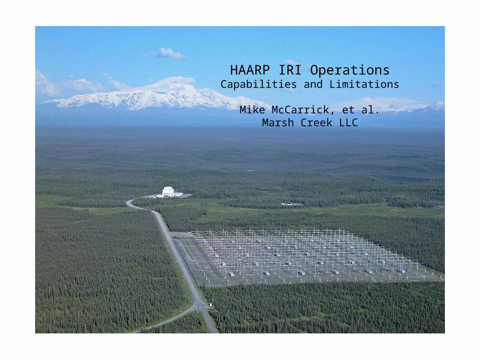
HAARP IRI Operations Capabilities and Limitations Mike McCarrick, et al. Marsh Creek LLC
32
HAARP IRI Operations Capabilities and Limitations Mike McCarrick, et al. Marsh Creek LLC
-
Upload
robert-barr -
Category
Documents
-
view
38 -
download
3
description
HAARP IRI Operations Capabilities and Limitations Mike McCarrick, et al. Marsh Creek LLC. Presentation Overview. Ionospheric Research Instrument (IRI) Phased Array Static performance Beam shape, beam pointing Active impedance (scan impedance) - PowerPoint PPT Presentation
Transcript of HAARP IRI Operations Capabilities and Limitations Mike McCarrick, et al. Marsh Creek LLC
HAARP IRI OperationsCapabilities and Limitations
Mike McCarrick, et al.Marsh Creek LLC
Presentation Overview
• Ionospheric Research Instrument (IRI) Phased Array
• Static performance
• Beam shape, beam pointing
• Active impedance (scan impedance)
• Frequency dependent effective radiated power (ERP)
• IRI Control System
• Control system features
• Modulation capabilities
• A few examples

True NorthMagnetic North: 20.3° in 2012
-0.3° per year
HAARP IRI 12x15 Planar Phased Arrayoriented 14° E of N
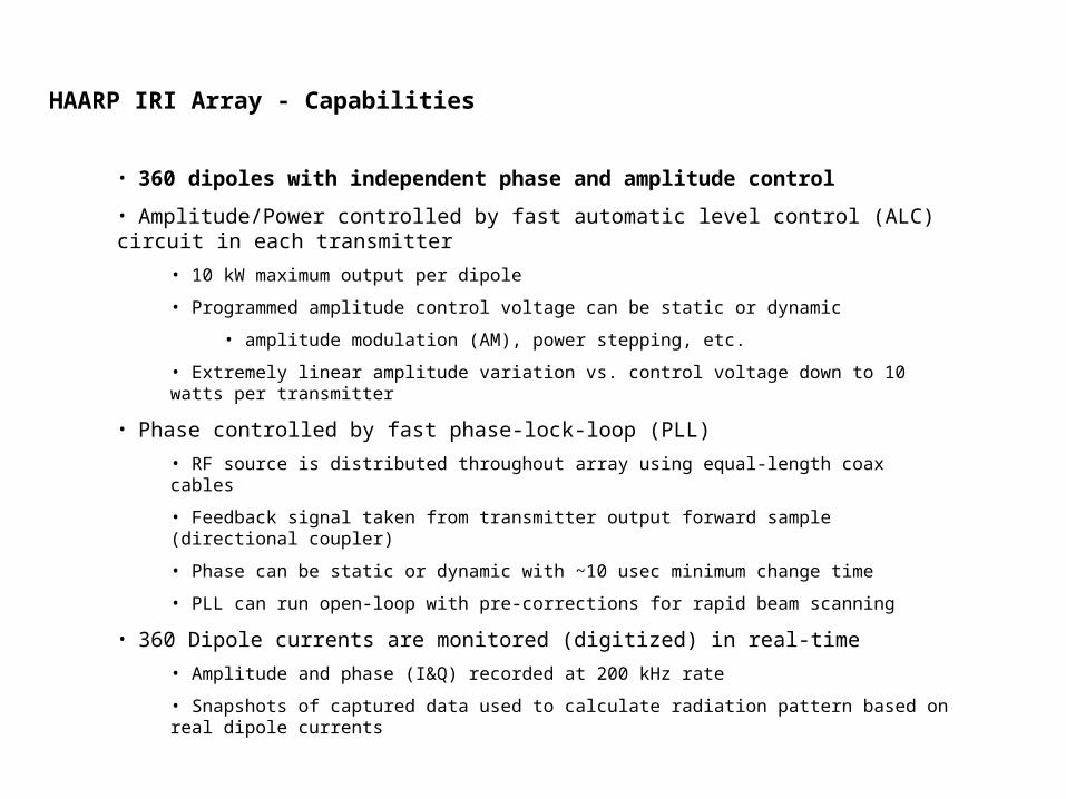
HAARP IRI Array - Capabilities
• 360 dipoles with independent phase and amplitude control
• Amplitude/Power controlled by fast automatic level control (ALC) circuit in each transmitter
• 10 kW maximum output per dipole
• Programmed amplitude control voltage can be static or dynamic
• amplitude modulation (AM), power stepping, etc.
• Extremely linear amplitude variation vs. control voltage down to 10 watts per transmitter
• Phase controlled by fast phase-lock-loop (PLL)
• RF source is distributed throughout array using equal-length coax cables
• Feedback signal taken from transmitter output forward sample (directional coupler)
• Phase can be static or dynamic with ~10 usec minimum change time
• PLL can run open-loop with pre-corrections for rapid beam scanning
• 360 Dipole currents are monitored (digitized) in real-time
• Amplitude and phase (I&Q) recorded at 200 kHz rate
• Snapshots of captured data used to calculate radiation pattern based on real dipole currents

HAARP IRI Array - Limitations
• Dipoles are large structures, closely spaced, and therefore coupled electromagnetically
• Active ALC and PLL maintains correct forward power and phase despite tight coupling
• However, coupling strongly affects the impedance seen by each transmitter
• Transmitters must be tuned to something close to this “active impedance”
• Severely mismatched transmitters may not be able to operate (or may operate at reduce output)
• Cannot switch between very different phase conditions without retuning
• Beam pointing angle change > 15 deg requires retuning
• Broadened beam requires retuning vs. normal beam
• Most “novel” beam modes require retuning vs. normal beam
• Retuning requires up to 30 seconds OFF
• Power can only be reduced from 10 kW per dipole
• Gaussian beam modes (tapered excitation) always result in lower ERP
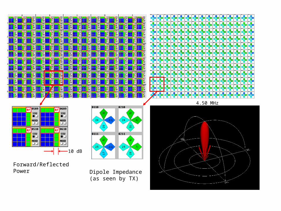
Dipole Impedance(as seen by TX)
Forward/ReflectedPower
4.50 MHz
10 dB
0° 0° 0° 0° 0° 0° 0° 0° 0° 0° 0° 0°
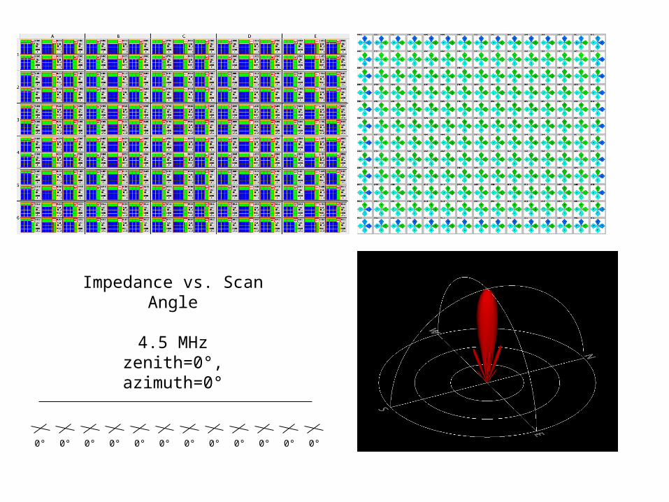
Impedance vs. Scan Angle
4.5 MHzzenith=0°, azimuth=0°

Impedance vs. Scan Angle
4.5 MHzzenith=15°, azimuth=0°
375° 341° 306° 273° 238° 204° 170° 136° 102° 68° 34° 0°
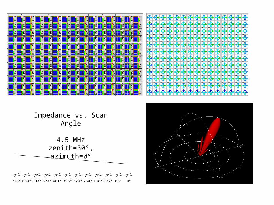
Impedance vs. Scan Angle
4.5 MHzzenith=30°, azimuth=0°
725° 659° 593° 527° 461° 395° 329° 264° 198° 132° 66° 0°

Impedance vs. Scan Angle
4.5 MHzzenith=45°, azimuth=0°
1025° 932° 839° 745° 652° 559° 466° 373° 280° 186° 93° 0°

Impedance vs. Scan Angle
4.5 MHzzenith=60°, azimuth=0°
1255°1141°1027° 913° 799° 685° 571° 456° 342° 228° 114° 0°

HAARP IRI Array - Dipole Coupling
• IRI Array is designed to operate best with a normal beam within 15 deg of broadside
• Antenna matching circuits were optimized for this condition, given the known coupling
• Low-frequency performance (e.g., < 4 MHz) actually requires coupling
• Isolated dipoles have nearly full reflection without neighbors
• Dipole coupling affects our ability to operate with arbitrary phasing
• Impedance may improve or worsen depending on neighboring phases and operating frequency
• Significant impedance mismatch (vs. 50 ohms) means high reflection, low radiated power
• If impedance mismatched is too high, transmitter may not be able to operate at all

2.7 MHz Magnetic Zenith

3.4 MHz Magnetic Zenith
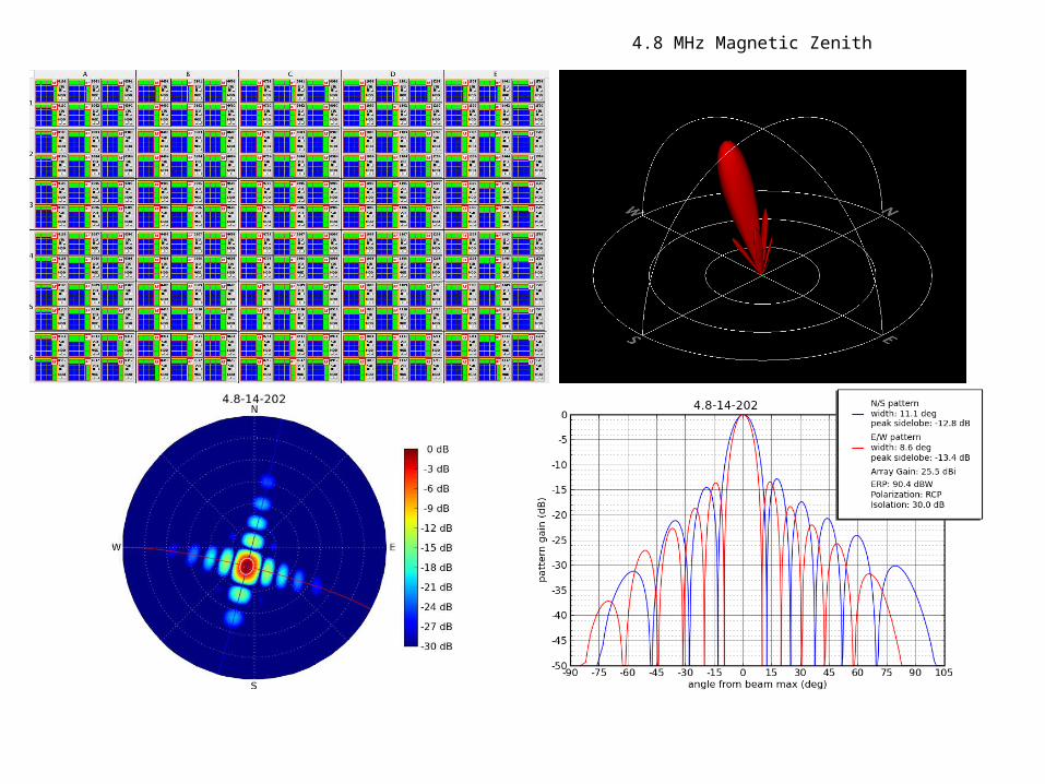
4.8 MHz Magnetic Zenith
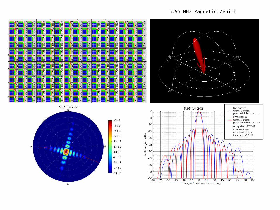
5.95 MHz Magnetic Zenith

6.8 MHz Magnetic Zenith

7.8 MHz Magnetic Zenith

9.2 MHz Magnetic Zenith
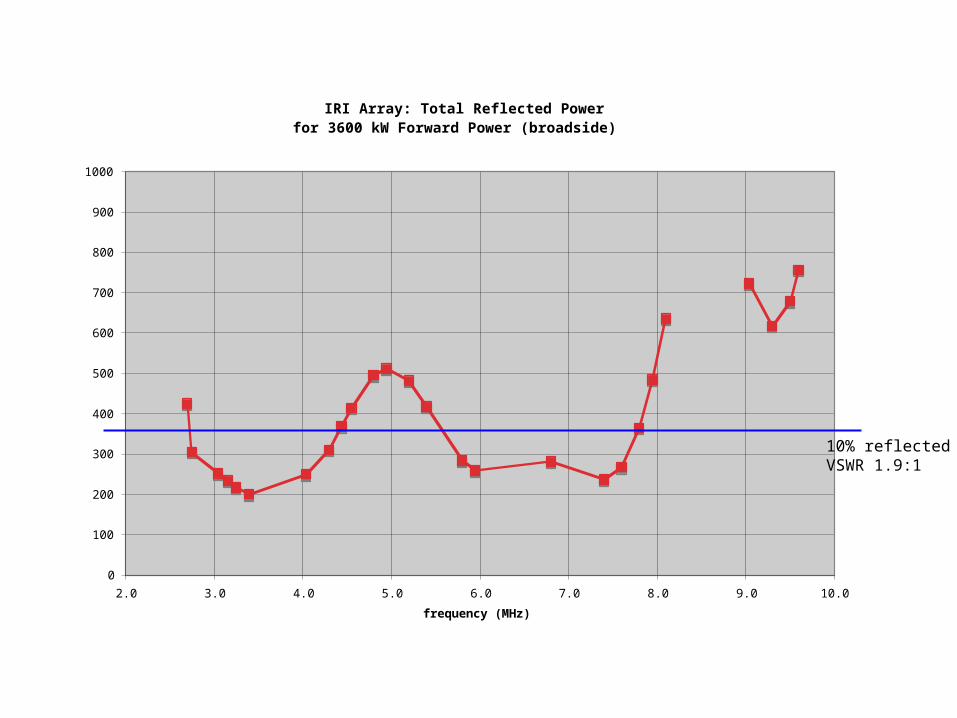
IRI Array: Total Reflected Powerfor 3600 kW Forward Power (broadside)
0
100
200
300
400
500
600
700
800
900
1000
2.0 3.0 4.0 5.0 6.0 7.0 8.0 9.0 10.0
frequency (MHz)
tota
l re
flecte
d p
ow
er
(kW
)
10% reflectedVSWR 1.9:1
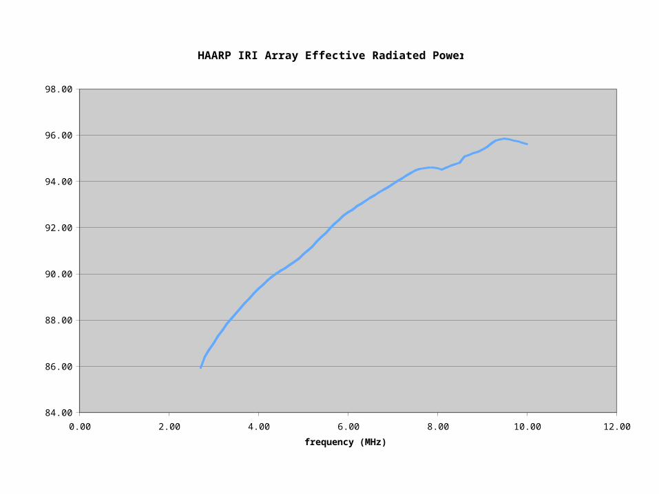
HAARP IRI Array Effective Radiated Power
84.00
86.00
88.00
90.00
92.00
94.00
96.00
98.00
0.00 2.00 4.00 6.00 8.00 10.00 12.00
frequency (MHz)
ER
P (
dB
W)
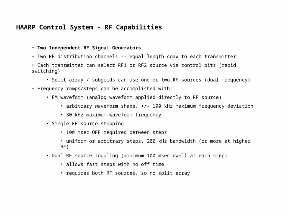
HAARP Control System - RF Capabilities
• Two Independent RF Signal Generators
• Two RF distribution channels -- equal length coax to each transmitter
• Each transmitter can select RF1 or RF2 source via control bits (rapid switching)
• Split array / subgrids can use one or two RF sources (dual frequency)
• Frequency ramps/steps can be accomplished with:
• FM waveform (analog waveform applied directly to RF source)
• arbitrary waveform shape, +/- 100 kHz maximum frequency deviation
• 30 kHz maximum waveform frequency
• Single RF source stepping
• 100 msec OFF required between steps
• uniform or arbitrary steps, 200 kHz bandwidth (or more at higher HF)
• Dual RF source toggling (minimum 100 msec dwell at each step)
• allows fast steps with no off time
• requires both RF sources, so no split array

HAARP Control System - Modulation Capabilities
• Two Independent Modulation Sources
• Direct digital synthesis at 200 kHz
• Digital waveform data injected directly into real-time control data stream
• D/A conversion takes place at transmitter input
• Modulation states locked to power/phase control states
• Allows synchronized power control and beam pointing with modulation change
• Starting phase always well defined with respect to experiment start (i.e. GPS time)
• Arbitrarily complex sequences of modulation states can be created
• Timing and frequency accuracy provided by 10 MHz rubidium frequency standard
• Locked to GPS for long-term stability
• Distributed throughout site for locked receiver applications

HAARP Control System - Modulation Capabilities (AM and FM)
• Waveforms
• Sine, half-sine, rectified sine (sqrt sine), square, sawtooth
• Any waveform that can be defined as a function of phase angle can be added
• Any waveform can be used with any frequency type (e.g. fixed or ramp)
• Modulation frequencies
• Fixed, linear ramp, log ramp, parabolic ramp
• 0-30 kHz range
• All modulation frequencies are precise -- locked to common 10 MHz reference
• WAV file
• For very complex waveforms, user can provide a WAV format file
• Any sample rate -- internally resampled to 200 kHz
• -32767/+32767 (16 bit signed) data range translates to 0-100% output (amplitude modulation)

HAARP Control System - Modulation Capabilities (Pulse)
• Direct Digital Synthesis at 1 MHz sample rate
• Single Pulse (width, delay)
• 80 dB on/off ratio
• Minimum pulse width: 10 µsec
• Width/delay resolution: 1 µsec
• PRF: 0-30 kHz
• Pulse Train (arbitrary list of widths and delays)
• Coded Pulse
• Barker (2-13 chips) or user supplied (e.g. “11100010010”)
• Coded via bi-phase (0/180 RF phase switching)
• 10 µsec minimum chip length
• Pulse shaping applied at transmitter low-level drive
• Selectable risetime (1 - 10,000 µsec)
• Selectable shape: 1% truncated gaussian or raised cosine
• 100 MHz D/A shaping via look-up table

Example: Complicated frequency-time modulation experiment
This was an ELF experiment conducted during the Optics 2008 campaign, designed to scatter bursts of electrons out of the loss cone, producing optical emission
Freq-time curves were the result of a modeling program (provided by PI)
Accomplished with a script that converts freq-time data to multiple linear freq ramp segments, with generated waveforms stored in WAV files

Spectrogram of transmitted waveform:

Another example (not so scientifically useful but…)

Dual-Frequency Transmission: North/South Split Array
For closely-spaced frequencies, the offset in sub-array phase centers produces an interference pattern in the radiation…

Beam Scanning: North/South Sawtooth Sweep
… very similar to a beam scanning mode

Synthesized Two-Frequency Mode
Sqrt-sine modulation waveform synchronized with180 deg RF phase change produces pure two-frequencytransmission

In Summary…
• HAARP offers a great advantage to active ionospheric modification experiments
• High radiated power (3.6 MW transmitted, up to 4 GW ERP)
• Tremendous flexibility in
• transmit frequency
• beam control
• split array
• complex modulation types
• software-based control system