HA 210H-3 HA 288 21 MPa Double Acting Hydraulic Cylinder 289 · 210H-3 21 MPa Double Acting...
13
21 MPa Double Acting Hydraulic Cylinder 210H-3 210H-3 General Hydraulic Cylinders 288 HA 21 MPa Double Acting Hydraulic Cylinder 210H-3 General Hydraulic Cylinders 210H-3 289 HA Nominal pressure Maximum allowable pressure Proof test pressure Minimum operating pressure Working speed range Structure of cushioning Adaptable fluid Tolerance for thread Tolerance of stroke Mounting style 21 MPa hydraulic cylinders ●Double acting hydraulic cylinders for 21 MPa with bores from 40 to 160 mm. ●The performance and mounting dimensions conform to the standard of Japan Fluid Power Association (JOHS). Standard Specifications Standard type Type Nominal pressure Pressure given to a cylinder for convenience of naming. It is not always the same as the working pressure (rated pressure) that guarantees performance under the specified conditions. Maximum allowable pressure The maximum allowable pressure generated in a cylinder (surge pressure, etc.). Proof test pressure Test pressure against which a cylinder can withstand without unreliable performance at the return to nominal pressure. Minimum operating pressure The minimum pressure that a cylinder placed horizontally without a load can work. Notes)●The hydraulic pressure generated in a cylinder due to the inertia of load must be lower than the maximum allowable pressure. ●In case that the lock nut is attached to the piston rod end thread part, increase the thread length (dimension A). ●For the internal structure, refer to the sectional drawings at the end of this catalog. ●Conex, material of the boots, is the registered trademark of Teijin Limited. Terminologies Petroleum-based fluid (When using another fluid, refer to the table of fluid adaptability.) Working temperature range (ambient/fluid temperature) Boots Rod end attachments Other Accessories 21 MPa Metal fitting system JIS 6g/6H 0 to 100 mm 0101 to 0250mm 0 251 to 0630mm 631 to 1000mm 1001 to 1600mm 1601 to 2000mm +0.8 0 +1.4 0 +1.0 0 +1.6 0 +1.25 0 +1.8 0 SD, LA, FA, FB, CA, CB, TA, TC Standard: Nylon tarpaulin Semi-standard: Chloroprene, Conex Rod eye (T-end), rod clevis (Y-end) with pin Lock nut Standard Stroke Range Unit: mm Cushion Stroke Length Unit: mm Cylinder bore f40 to f63 f80 to f160 Note) The cushion stroke lengths in case of cylinders used up to the stroke end. 20 25 Cushion ring length on rod side Cap side: 24.5 MPa Rod side: 26.5 MPa 31.5 MPa Rod side: 0.45 MPa or less Cap side: 0.3 MPa or less 8 to 300 mm/s (excluding cushion) -10 to +80℃ (No freezing) Bore Stroke f40 f50 to f160 1500 2000 ●The above strokes indicate the maximum available strokes for the standard type. ●For the rod buckling, check with the buckling chart in the selection materials. Contact us for longer strokes. 20 25 Cushion ring length on cap side Seal material Adaptable fluid Oil in water fluid Water in oil fluid Phosphate ester fluid Water-glycol fluid Petroleum- based fluid Product Lineup General purpose type Double acting single rod Standard type Unit: mm Series Variation Type f40 210H-3 f50 f63 f80 f100 f125 f140 f160 Weight Table Unit: kg Rod end attachment weight Mounting accessory weight Bore mm f40 f50 f63 f80 f100 f125 f140 f160 4.44 8.06 13.2 23.6 39.6 68.5 92.4 126 0.0122 0.0202 0.0293 0.0451 0.0738 0.121 0.164 0.192 LA 0.964 1.11 1.27 1.91 5.11 8.50 5.20 4.70 FA 0.7 1.2 1.9 2.0 4.4 10.0 8.6 13.7 FB 1.0 1.9 3.7 4.7 9.7 18.6 21.8 30.0 CA 0.7 1.3 2.0 3.4 6.4 13.2 16.5 25.6 CB 0.7 1.1 1.7 3.0 5.2 11.0 13.4 20.4 TA 0.4 0.4 0.6 1.0 2.1 4.0 5.2 7.1 0.969 1.49 2.03 2.91 7.61 13.0 15.1 23.7 1.0 1.4 2.2 4.2 8.0 31.1 36.7 58.8 1.2 2.2 3.7 7.7 14.6 20.5 24.4 41.1 0.03 0.05 0.11 0.24 0.52 1.10 1.44 1.93 Basic weight Additional weight per mm of stroke Rod eye (T-end) Rod clevis (Y-end) w/ pin Lock nut Adaptability of Fluid to Seal Material Nitrile rubber Urethane rubber Fluorocarbon HNBR ○ △ ○ ◎ ○ △ ○ ◎ × × ○ × ○ × × ◎ ○ ◎ ○ ○ TC 2 3 6 1 Notes) 2. The ◎-marked items are recommended seal materials in case of giving the first priority to abrasion resistance. 1. ◎○: Applicable, ×: Inapplicable. Consult us before using the △-marked items. Calculation formula Cylinder weight (kg)=basic weight+(cylinder stroke (mm)×additional weight per mm of stroke) +mounting accessory weight+rod end attachment weight) 210H-3, bore φ100, cylinder stroke 500 mm, LA style 39.6+(500×0.0738)+5.11=81.61kg Calculation example
Transcript of HA 210H-3 HA 288 21 MPa Double Acting Hydraulic Cylinder 289 · 210H-3 21 MPa Double Acting...
21 MPa Double Acting Hydraulic Cylinder210H-3210H-3 General Hydraulic Cylinders
288HA
21 MPa Double Acting Hydraulic Cylinder 210H-3General H
ydraulic Cylinders
210H-3
289HA
Nominal pressure
Maximum allowable pressure
Proof test pressure
Minimum operating pressure
Working speed range
Structure of cushioning
Adaptable fluid
Tolerance for thread
Tolerance of stroke
Mounting style
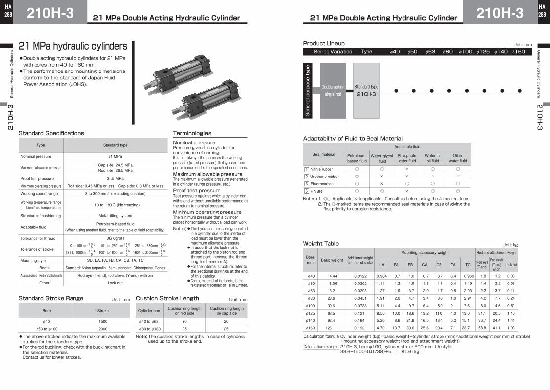
21 MPa hydraulic cylinders●Double acting hydraulic cylinders for 21 MPa with bores from 40 to 160 mm.●The performance and mounting dimensions conform to the standard of Japan Fluid Power Association (JOHS).
Standard Specifications
Standard typeType Nominal pressurePressure given to a cylinder for convenience of naming.It is not always the same as the working pressure (rated pressure) that guarantees performance under the specified conditions.Maximum allowable pressureThe maximum allowable pressure generated in a cylinder (surge pressure, etc.).Proof test pressureTest pressure against which a cylinder can withstand without unreliable performance at the return to nominal pressure.Minimum operating pressureThe minimum pressure that a cylinder placed horizontally without a load can work.Notes)●The hydraulic pressure generated
in a cylinder due to the inertia of load must be lower than the maximum allowable pressure.●In case that the lock nut is attached to the piston rod end thread part, increase the thread length (dimension A).
●For the internal structure, refer to the sectional drawings at the end of this catalog.●Conex, material of the boots, is the registered trademark of Teijin Limited.
Terminologies
Petroleum-based fluid
(When using another fluid, refer to the table of fluid adaptability.)
Working temperature range(ambient/fluid temperature)
Boots
Rod end attachments
Other
Accessories
21 MPa
Metal fitting system
JIS 6g/6H
0 to 100 mm 0101 to 0250mm 0 251 to 0630mm
631 to 1000mm 1001 to 1600mm 1601 to 2000mm
+0.8 0+1.4 0
+1.0 0+1.6 0
+1.25 0+1.8 0
SD, LA, FA, FB, CA, CB, TA, TC
Standard: Nylon tarpaulin Semi-standard: Chloroprene, Conex
Rod eye (T-end), rod clevis (Y-end) with pin
Lock nut
Standard Stroke Range Unit: mm Cushion Stroke Length Unit: mm
Cylinder bore
f40 to f63
f80 to f160
Note) The cushion stroke lengths in case of cylinders used up to the stroke end.
20
25
Cushion ring lengthon rod side
Cap side: 24.5 MPaRod side: 26.5 MPa
31.5 MPa
Rod side: 0.45 MPa or less Cap side: 0.3 MPa or less
8 to 300 mm/s (excluding cushion)
-10 to +80℃ (No freezing)
Bore Stroke
f40
f50 to f160
1500
2000
●The above strokes indicate the maximum available strokes for the standard type.●For the rod buckling, check with the buckling chart in the selection materials.Contact us for longer strokes.
20
25
Cushion ring lengthon cap side
Seal material
Adaptable fluid
Oil in water fluid
Water in oil fluid
Phosphate ester fluid
Water-glycol fluid
Petroleum-based fluid
Product Lineup
General purpose type
Double actingsingle rod
Standard type
Unit: mm
Series Variation Type f40
210H-3
f50 f63 f80 f100 f125 f140 f160
Weight Table Unit: kg
Rod end attachment weightMounting accessory weightBoremm
f40
f50
f63
f80
f100
f125
f140
f160
4.44
8.06
13.2
23.6
39.6
68.5
92.4
126
0.0122
0.0202
0.0293
0.0451
0.0738
0.121
0.164
0.192
LA
0.964
1.11
1.27
1.91
5.11
8.50
5.20
4.70
FA
0.7
1.2
1.9
2.0
4.4
10.0
8.6
13.7
FB
1.0
1.9
3.7
4.7
9.7
18.6
21.8
30.0
CA
0.7
1.3
2.0
3.4
6.4
13.2
16.5
25.6
CB
0.7
1.1
1.7
3.0
5.2
11.0
13.4
20.4
TA
0.4
0.4
0.6
1.0
2.1
4.0
5.2
7.1
0.969
1.49
2.03
2.91
7.61
13.0
15.1
23.7
1.0
1.4
2.2
4.2
8.0
31.1
36.7
58.8
1.2
2.2
3.7
7.7
14.6
20.5
24.4
41.1
0.03
0.05
0.11
0.24
0.52
1.10
1.44
1.93
Basic weightAdditional weightper mm of stroke Rod eye
(T-end)
Rod clevis(Y-end)w/ pin
Lock nut
Adaptability of Fluid to Seal Material
Nitrile rubber
Urethane rubber
Fluorocarbon
HNBR
○
△
○
◎
○
△
○
◎
×
×
○
×
○
×
×
◎
○
◎
○
○
TC
2
3
6
1
Notes)2. The ◎-marked items are recommended seal materials in case of giving thefirst priority to abrasion resistance.
1. ◎○: Applicable, ×: Inapplicable. Consult us before using the △-marked items.
Calculation formula Cylinder weight (kg)=basic weight+(cylinder stroke (mm)×additional weight per mm of stroke)+mounting accessory weight+rod end attachment weight)210H-3, bore φ100, cylinder stroke 500 mm, LA style39.6+(500×0.0738)+5.11=81.61kg
Calculation example

21 MPa Double Acting Hydraulic Cylinder210H-3210H-3 General Hydraulic Cylinders
290HA
21 MPa Double Acting Hydraulic Cylinder 210H-3General H
ydraulic Cylinders
210H-3
291HA
Seal material
Adaptable fluid
Petroleum-based fluid
Phosphateester fluid
Water in oil fluid
Oil in water fluid
Water-glycol fluid
Port position (A, B, C, D)Cushion valve position (A, B, C, D, 0)
●Standard type
Standard specifications
●With cushions on both ends●Port position Ⓐ, cushion valve position Ⓑ
Standard range●Change of piston rod end●Change of TC accessory position (dimensional symbol: PH)●With boots●Plated cylinder tube(hard chrome plating thickness: 0.02 mm)
Change of port positionWhen modifying the positions, enter the symbol shown in the dimensional drawings.(Example) 210H-3 2SD50BB100- B C -J
●In case that the cushion is not equipped, the cushion valve position is 0.
210H-3 2 LA 50 B B 100 - -
Mounting style With lock nut
Cylinder bore (mm)f40・f50・f63・f80・f100・f125・f140・f160
Cylinder stroke (mm)Rod type: Rod B
With cushions on both endsWith cushion on rod sideWith cushion on cap sideNo cushion
Rod eye (T-end)Rod clevis (Y-end)
Standard Stroke Range Unit: mm
Bore Stroke
f40
f50 to f160
1500
2000
●The above strokes indicate the maximum available strokes for the standard type.●For the rod buckling, check with the buckling chart in the selection materials.Contact us for longer strokes.
Adaptability of Fluid to Seal Material
Nitrile rubber
Urethane rubber
Fluorocarbon
HNBR
Notes) 1. ◎○: Applicable, ×: Inapplicable. Consult us before using the △-marked items.
2. The ◎-marked items are recommended seal materials in case of giving the first priority to abrasion resistance.
○
△
○
◎
○
△
○
◎
×
×
○
×
○
×
×
◎
○
◎
○
○
Nitrile rubberUrethane rubberFluorocarbonHNBR
Nylon tarpaulinChloropreneConex
NJNJNJK
JLT
Note) There are check valves on two sides out of the four outer sides of cap and rod covers except the port and cushion sides. The check valve is concurrently used with air vent.
Type❶
Seal material❷
Mounting style❸
Cylinder bore❹
Rod type❺
Cushioning❻
Stroke❼
Rod end attachment❽
Lock nut❾
Boots10
2
3
6
1
Ⓐ
ⒷⒹ
Ⓒ
236
1
General Purpose Type Semi-standard specificationThe item enclosed by broken line needs not to be entered, if unnecessary. Mounting style
SD style (basic style)SD FB style (cap flange)FB
LA style (side lugs)LA CA style (cap eye)CA
TA style (rod trunnion)TA
TC style (intermediate trunnion)TC
Cushion valve and check valve (air vent) positions depending on cylinder bore (when port is on A and cushion is on B)
FA style (rod flange)FA CB style (cap clevis)CB
Check valve(air vent)
Check valve(air vent)
Cushion valveBore 40 mm
Bore 50・63 mm
Bore 80・100 mm
Bore 125・140・160 mm
Delivery of rod end attachment (T-end or Y-end)A delivery method for a cylinder provided with a lock nut and a rod end attachment differs from that for a cylinder provided with a rod end attachment only (without a lock nut). For details, refer to the dimensional drawings of rod end attachments.
Hex. screw is not supplied.Tapped hole only.Rod end attachment
Rod end attachment
Drilled
Hex. screw (full dog point)
Piston rod
Piston rodLock nut
●When the lock nut and rod end attachment are additionally ordered
●When only the rod end attachment is additionally ordered (without lock nut)
●How to order
21 MPa Double Acting Hydraulic CylinderDouble Acting Single Rod210H-3292
HA210H-3 General Hydraulic Cylinders
21 MPa Double Acting Hydraulic CylinderDouble Acting Single Rod 210H-3 293
HAGeneral H
ydraulic Cylinders
210H-3
Unit: mm Unit: mm
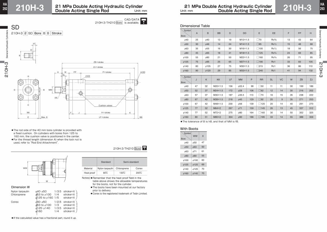
SD210H-3 2 SD
2-EE
4-DD
KK
MM
Cushion valves
H+stroke
LF+stroke
P+stroke
ZJ+stroke
ZB+stroke
Ⓐ
Ⓑ
Ⓒ
Ⓓ
JF K
Max. 6 BB
FPWSL
A
VC
RR
E
B
D
WW
W
Nylon tarpaulin f40・f50 1/3.5 stroke+XChloroprene f63 to f100 1/4 stroke+X
f125 to f160 1/5 stroke+X
Conex f40・f50 1/2.5 stroke+Xf63 to f100 1/3 stroke+Xf125・f140 1/3.5 stroke+Xf160 1/4 stroke+X
⎞⎟⎠⎞⎟⎟⎠
⎞⎟
⎠⎞
⎟⎟
⎠
●If the calculated value has a fractional part, round it up.
●The rod side of the 40 mm bore cylinder is provided with a fixed cushion. On cylinders with bores from 125 to 160 mm, the cushion valve is positioned in the center.●For the thread length (dimension A) when the lock nut is used, refer to “Rod End Attachment”.
Dimension W
Standard Semi-standard
Material
Heat proof
Nylon tarpaulin Chloroprene Conex
80℃ 130℃ 200℃
Notes)●Remember that the heat proof field in the table above shows the allowable temperatures for the boots, not for the cylinder.●The boots have been mounted at our factory prior to delivery.●Conex is the registered trademark of Teijin Limited.
210H-3/TH210 Bore
Bore B B Stroke
f40
f50
f63
f80
f100
f125
f140
f160
A
25
30
35
45
55
75
80
90
B
f40
f46
f55
f65
f80
f95
f105
f120
BB
13
14
16
18
21
25
27
29
D
19
24
30
41
50
65
75
85
DD
M12×1.5
M14×1.5
M16×1.5
M18×1.5
M22×1.5
M27×1.5
M30×1.5
M33×1.5
E
□70
□85
□100
□125
□160
□190
□215
□240
EE
Rc3/8
Rc1/2
Rc1/2
Rc3/4
Rc3/4
Rc1
Rc1
Rc1
F
13
15
18
24
26
33
36
41
FP
43
48
56
69
71
83
86
94
H
64
68
75
85
95
105
110
132
f40
f50
f63
f80
f100
f125
f140
f160
J
47
52
57
67
67
77
77
80
K
32
37
37
42
42
52
52
51
KK
M20×1.5
M24×1.5
M30×1.5
M39×1.5
M48×1.5
M64×2
M72×2
M80×2
LF
156
172
187
218
230
267
275
304
MM
f22.4
f28
f35.5
f45
f56
f71
f80
f90
P
98
106
113
129
139
159
164
186
RR
□50
□62
□74
□92
□120
□145
□165
□185
VC
11
14
15
9
14
13
14
14
W
30
30
35
35
40
45
50
55
ZB
199
216
238
271
291
337
352
388
ZJ
186
202
222
253
270
312
325
359
Dimensional Table
With Boots
f40
f50
f63
f80
f100
f125
f140
f160
f50
f63
f71
f80
f100
f125
f125
f140
WW
47
50
61
55
60
69
70
70
X
SL
11
12
16
20
20
26
30
33
●The tolerance of B is h8, and that of MM is f8.
Symbol
Bore
Symbol
Bore
Symbol
Bore
CAD/DATAis available.210H-3/TH210 Bore

21 MPa Double Acting Hydraulic CylinderDouble Acting Single Rod210H-3294
HA210H-3 General Hydraulic Cylinders
21 MPa Double Acting Hydraulic CylinderDouble Acting Single Rod 210H-3 295
HAGeneral H
ydraulic Cylinders
210H-3
Unit: mm Unit: mm
LA210H-3 2 LA
2-EE
KK
MM
Cushion valves
P+stroke
ZB+stroke
SS+stroke
XW+stroke
4-SB
KFPW
SL
A
VC
E Max. 6
TS
US
SZSWYS VS
XS
B
Ⓐ
Ⓑ
Ⓒ
ⒹLE
ST
LH
D
WW
W
Dimension WNylon tarpaulinChloroprene
Conex
●If the calculated value has a fractional part, round it up.
Bore B B Stroke
●The rod side of the 40 mm bore cylinder is provided with a fixed cushion. On cylinders with bores from 125 to 160 mm, the cushion valve is positioned in the center.●For the thread length (dimension A) when the lock nut is used, refer to “Rod End Attachment”.
f40・f50 1/3.5 stroke+Xf63 to f100 1/4 stroke+Xf125 to f160 1/5 stroke+X
f40・f50 1/2.5 stroke+Xf63 to f100 1/3 stroke+Xf125・f140 1/3.5 stroke+Xf160 1/4 stroke+X
⎞⎟⎠⎞⎟⎟⎠
⎞⎟
⎠⎞
⎟⎟
⎠
Standard Semi-standard
Material
Heat proof
Chloroprene Conex
80℃ 130℃ 200℃
Notes)●Remember that the heat proof field in the table above shows the allowable temperatures for the boots, not for the cylinder.●The boots have been mounted at our factory prior to delivery.●Conex is the registered trademark of Teijin Limited.
210H-3/TH210 Bore
Nylon tarpaulin
f40
f50
f63
f80
f100
f125
f140
f160
A
25
30
35
45
55
75
80
90
Dimensional Table
B
f40
f46
f55
f65
f80
f95
f105
f120
D
19
24
30
41
50
65
75
85
E
□70
□85
□100
□125
□160
□190
□215
□240
EE
Rc3/8
Rc1/2
Rc1/2
Rc3/4
Rc3/4
Rc1
Rc1
Rc1
FP
43
48
56
69
71
83
86
94
K
32
37
37
42
42
52
52
51
LE
77
97.5
113
137.5
165
200
219.5
245
LH
42±0.15
55±0.15
63±0.15
75±0.25
85±0.25
105±0.25
112±0.25
125±0.25
MM
f22.4
f28
f35.5
f45
f56
f71
f80
f90
P
98
106
113
129
139
159
164
186
SB
f11
f14
f18
f22
f26
f33
f33
f36
f40
f50
f63
f80
f100
f125
f140
f160
SL
11
12
16
20
20
26
30
33
With Boots
f40
f50
f63
f80
f100
f125
f140
f160
f50
f63
f71
f80
f100
f125
f125
f140
WW
47
50
61
55
60
69
70
70
X
KK
M20×1.5
M24×1.5
M30×1.5
M39×1.5
M48×1.5
M64×2
M72×2
M80×2
SS
111
120
132
152
162
182
187
212
ST
15
20
25
30
35
45
45
50
SV
31
34
39
46
44
49
49
49
SW
16
18
18
21
23
28
28
31
SY
16
18
18
21
23
28
28
31
SZ
16
19
19
21
24
29
29
31
TS
98
118
140
175
215
270
280
315
US
122
145
175
210
260
330
335
375
VC
11
14
15
9
14
13
14
14
W
30
30
35
35
40
45
50
55
XS
59
63
71
80
89
106
114
127
XW
170
183
203
232
251
288
301
339
ZB
199
216
238
271
291
337
352
388
●The tolerance of B is h8, and that of MM is f8.
Symbol
Bore
Symbol
Bore
Symbol
Bore
CAD/DATAis available.210H-3/TH210 Bore
21 MPa Double Acting Hydraulic CylinderDouble Acting Single Rod210H-3296
HA210H-3 General Hydraulic Cylinders
21 MPa Double Acting Hydraulic CylinderDouble Acting Single Rod 210H-3 297
HAGeneral H
ydraulic Cylinders
210H-3
Unit: mm Unit: mm
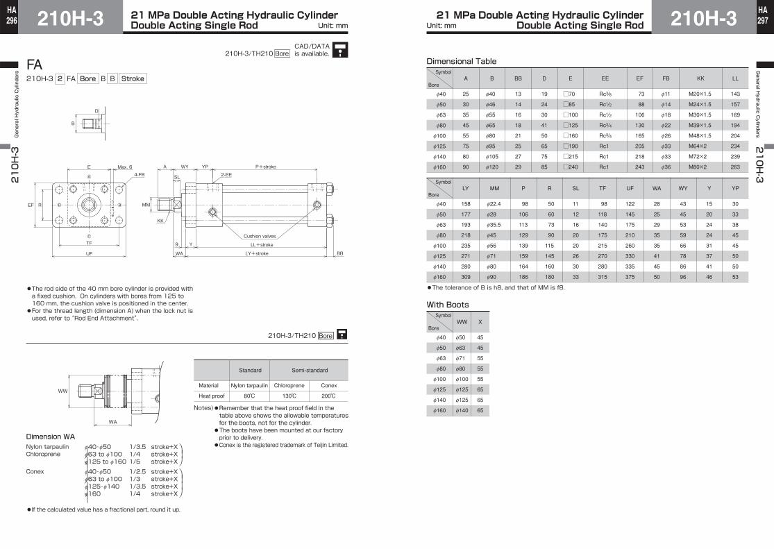
FA210H-3 2 FA
2-EE
KK
MM
Cushion valves
P+stroke
LL+stroke
LY+stroke
A WY
SL
YPE
EF R
Max. 64-FB
UF
Y9
WA BB
TF
B
Ⓐ
Ⓒ
D
Ⓓ Ⓑ
WW
WA
Bore B B Stroke
●The rod side of the 40 mm bore cylinder is provided with a fixed cushion. On cylinders with bores from 125 to 160 mm, the cushion valve is positioned in the center.●For the thread length (dimension A) when the lock nut is used, refer to “Rod End Attachment”.
f40・f50 1/3.5 stroke+Xf63 to f100 1/4 stroke+Xf125 to f160 1/5 stroke+X
f40・f50 1/2.5 stroke+Xf63 to f100 1/3 stroke+Xf125・f140 1/3.5 stroke+Xf160 1/4 stroke+X
⎞⎟⎠⎞⎟⎟⎠
⎞⎟
⎠⎞
⎟⎟
⎠
Standard Semi-standard
Material
Heat proof
Chloroprene Conex
80℃ 130℃ 200℃
Notes)●Remember that the heat proof field in the table above shows the allowable temperatures for the boots, not for the cylinder.●The boots have been mounted at our factory prior to delivery.●Conex is the registered trademark of Teijin Limited.
Dimension WANylon tarpaulinChloroprene
Conex
●If the calculated value has a fractional part, round it up.
210H-3/TH210 Bore
Nylon tarpaulin
Dimensional Table
f40
f50
f63
f80
f100
f125
f140
f160
A
25
30
35
45
55
75
80
90
B
f40
f46
f55
f65
f80
f95
f105
f120
EE
Rc3/8
Rc1/2
Rc1/2
Rc3/4
Rc3/4
Rc1
Rc1
Rc1
BB
13
14
16
18
21
25
27
29
D
19
24
30
41
50
65
75
85
E
□70
□85
□100
□125
□160
□190
□215
□240
EF
73
88
106
130
165
205
218
243
FB
f11
f14
f18
f22
f26
f33
f33
f36
KK
M20×1.5
M24×1.5
M30×1.5
M39×1.5
M48×1.5
M64×2
M72×2
M80×2
LL
143
157
169
194
204
234
239
263
f40
f50
f63
f80
f100
f125
f140
f160
LY
158
177
193
218
235
271
280
309
MM
f22.4
f28
f35.5
f45
f56
f71
f80
f90
P
98
106
113
129
139
159
164
186
With Boots
f40
f50
f63
f80
f100
f125
f140
f160
f50
f63
f71
f80
f100
f125
f125
f140
WW
45
45
55
55
55
65
65
65
X
R
50
60
73
90
115
145
160
180
SL
11
12
16
20
20
26
30
33
TF
98
118
140
175
215
270
280
315
UF
122
145
175
210
260
330
335
375
WA
28
25
29
35
35
41
45
50
WY
43
45
53
59
66
78
86
96
Y
15
20
24
24
31
37
41
46
YP
30
33
38
45
45
50
50
53
●The tolerance of B is h8, and that of MM is f8.
Symbol
Bore
Symbol
Bore
Symbol
Bore
CAD/DATAis available.210H-3/TH210 Bore

21 MPa Double Acting Hydraulic CylinderDouble Acting Single Rod210H-3298
HA210H-3 General Hydraulic Cylinders
21 MPa Double Acting Hydraulic CylinderDouble Acting Single Rod 210H-3 299
HAGeneral H
ydraulic Cylinders
210H-3
Unit: mm Unit: mm
FB210H-3 2 FB
2-EE
KK
Cushion valves
LF+stroke
ZY+stroke
P+stroke4-FB
EMax. 6
TF
UF
R EF
Y
FPWA
MM
Ⓐ
Ⓒ
Ⓑ
B
VC
D
Ⓓ
SL
WW
W
210H-3/TH210 Bore
Bore B B Stroke
f40・f50 1/3.5 stroke+Xf63 to f100 1/4 stroke+Xf125 to f160 1/5 stroke+X
f40・f50 1/2.5 stroke+Xf63 to f100 1/3 stroke+Xf125・f140 1/3.5 stroke+Xf160 1/4 stroke+X
⎞⎟⎠⎞⎟⎟⎠
⎞⎟
⎠⎞
⎟⎟
⎠
Standard Semi-standard
Material
Heat proof
Nylon tarpaulin Chloroprene Conex
80℃ 130℃ 200℃
Notes)●Remember that the heat proof field in the table above shows the allowable temperatures for the boots, not for the cylinder.●The boots have been mounted at our factory prior to delivery.●Conex is the registered trademark of Teijin Limited.
●The rod side of the 40 mm bore cylinder is provided with a fixed cushion. ●For the thread length (dimension A) when the lock nut is used, refer to “Rod End Attachment”.
Dimension WNylon tarpaulinChloroprene
Conex
●If the calculated value has a fractional part, round it up.
Dimensional Table
f40
f50
f63
f80
f100
f125
f140
f160
A
25
30
35
45
55
75
80
90
B
f40
f46
f55
f65
f80
f95
f105
f120
D
19
24
30
41
50
65
75
85
E
□70
□85
□100
□125
□160
□190
□215
□240
EE
Rc3/8
Rc1/2
Rc1/2
Rc3/4
Rc3/4
Rc1
Rc1
Rc1
EF
73
88
106
130
165
205
218
243
FB
f11
f14
f18
f22
f26
f33
f33
f36
FP
43
48
56
69
71
83
86
94
KK
M20×1.5
M24×1.5
M30×1.5
M39×1.5
M48×1.5
M64×2
M72×2
M80×2
With Boots
f40
f50
f63
f80
f100
f125
f140
f160
f50
f63
f71
f80
f100
f125
f125
f140
WW
47
50
61
55
60
69
70
70
X
f40
f50
f63
f80
f100
f125
f140
f160
LF
156
172
187
218
230
267
275
304
MM
f22.4
f28
f35.5
f45
f56
f71
f80
f90
P
98
106
113
129
139
159
164
186
R
50
60
73
90
115
145
160
180
SL
11
12
16
20
20
26
30
33
TF
98
118
140
175
215
270
280
315
UF
122
145
175
210
260
330
335
375
VC
11
14
15
9
14
13
14
14
W
30
30
35
35
40
45
50
55
Y
15
20
24
24
31
37
41
46
ZY
201
222
246
277
301
349
366
405
●The tolerance of B is h8, and that of MM is f8.
Symbol
Bore
Symbol
Bore
Symbol
Bore
CAD/DATAis available.210H-3/TH210 Bore
21 MPa Double Acting Hydraulic CylinderDouble Acting Single Rod210H-3300
HA210H-3 General Hydraulic Cylinders
21 MPa Double Acting Hydraulic CylinderDouble Acting Single Rod 210H-3 301
HAGeneral H
ydraulic Cylinders
210H-3
Unit: mm Unit: mm
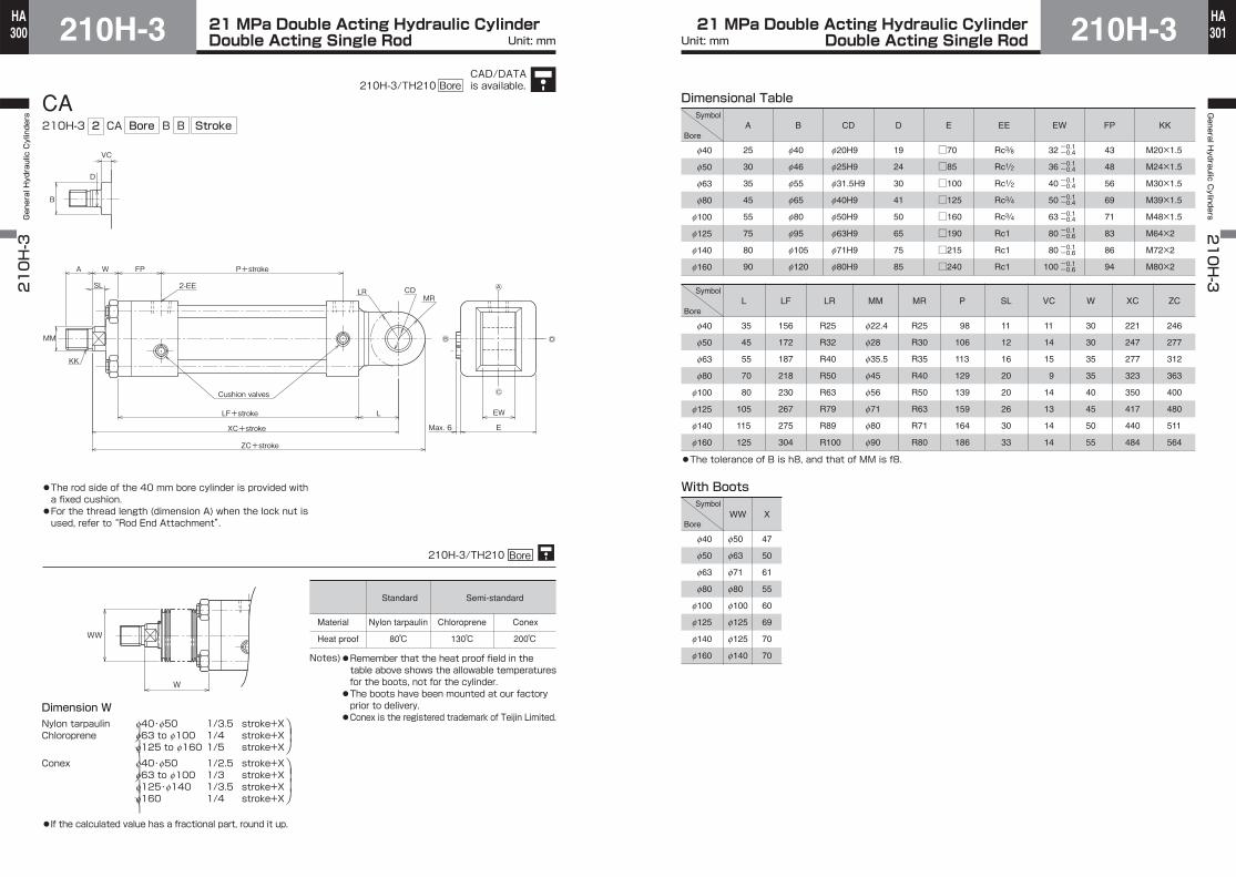
CA210H-3 2 CA
2-EE
KK
Cushion valves
LF+stroke
P+stroke
XC+stroke
ZC+stroke
A W FP
MM
L
E
EW
Ⓒ
Ⓑ
LRMR
CD
Ⓓ
Max. 6
VC
B
D
SL
WW
W
Ⓐ
210H-3/TH210 Bore
Bore B B Stroke
f40・f50 1/3.5 stroke+Xf63 to f100 1/4 stroke+Xf125 to f160 1/5 stroke+X
f40・f50 1/2.5 stroke+Xf63 to f100 1/3 stroke+Xf125・f140 1/3.5 stroke+Xf160 1/4 stroke+X
⎞⎟⎠⎞⎟⎟⎠
⎞⎟
⎠⎞
⎟⎟
⎠
Standard Semi-standard
Material
Heat proof
Chloroprene Conex
80℃ 130℃ 200℃
Notes)●Remember that the heat proof field in the table above shows the allowable temperatures for the boots, not for the cylinder.●The boots have been mounted at our factory prior to delivery.●Conex is the registered trademark of Teijin Limited.
●The rod side of the 40 mm bore cylinder is provided with a fixed cushion. ●For the thread length (dimension A) when the lock nut is used, refer to “Rod End Attachment”.
Dimension WNylon tarpaulinChloroprene
Conex
●If the calculated value has a fractional part, round it up.
Nylon tarpaulin
Dimensional Table
f40
f50
f63
f80
f100
f125
f140
f160
-0.1-0.4
-0.1-0.4
-0.1-0.4
-0.1-0.4
-0.1-0.4
-0.1-0.6
-0.1-0.6
-0.1-0.6
A
25
30
35
45
55
75
80
90
B
f40
f46
f55
f65
f80
f95
f105
f120
D
19
24
30
41
50
65
75
85
CD
f20H9
f25H9
f31.5H9
f40H9
f50H9
f63H9
f71H9
f80H9
E
□70
□85
□100
□125
□160
□190
□215
□240
EE
Rc3/8
Rc1/2
Rc1/2
Rc3/4
Rc3/4
Rc1
Rc1
Rc1
EW
32
36
40
50
63
80
80
100
FP
43
48
56
69
71
83
86
94
KK
M20×1.5
M24×1.5
M30×1.5
M39×1.5
M48×1.5
M64×2
M72×2
M80×2
With Boots
f40
f50
f63
f80
f100
f125
f140
f160
f50
f63
f71
f80
f100
f125
f125
f140
WW
47
50
61
55
60
69
70
70
X
f40
f50
f63
f80
f100
f125
f140
f160
L
35
45
55
70
80
105
115
125
LF
156
172
187
218
230
267
275
304
LR
R25
R32
R40
R50
R63
R79
R89
R100
MM
f22.4
f28
f35.5
f45
f56
f71
f80
f90
MR
R25
R30
R35
R40
R50
R63
R71
R80
P
98
106
113
129
139
159
164
186
SL
11
12
16
20
20
26
30
33
VC
11
14
15
9
14
13
14
14
W
30
30
35
35
40
45
50
55
XC
221
247
277
323
350
417
440
484
ZC
246
277
312
363
400
480
511
564
●The tolerance of B is h8, and that of MM is f8.
Symbol
Bore
Symbol
Bore
Symbol
Bore
CAD/DATAis available.210H-3/TH210 Bore
21 MPa Double Acting Hydraulic CylinderDouble Acting Single Rod210H-3302
HA210H-3 General Hydraulic Cylinders
21 MPa Double Acting Hydraulic CylinderDouble Acting Single Rod 210H-3 303
HAGeneral H
ydraulic Cylinders
210H-3
Unit: mm Unit: mm
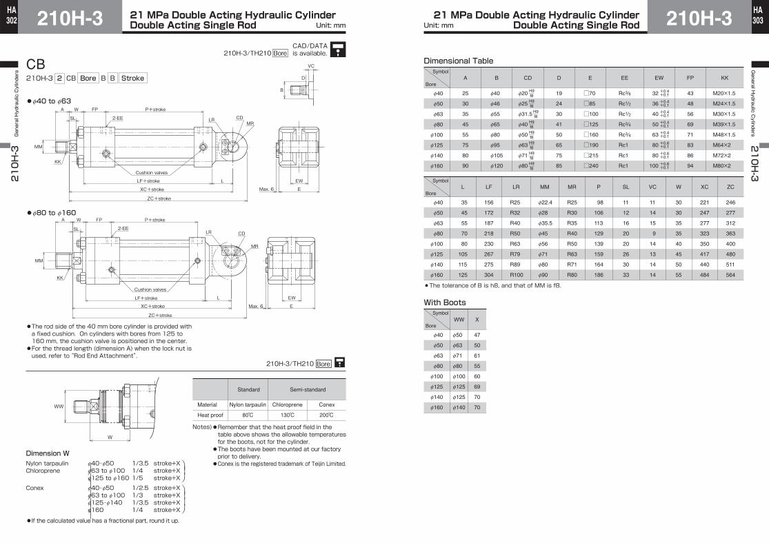
CB210H-3 2 CB
Cushion valves
P+stroke
LF+stroke
XC+stroke
ZC+stroke
2-EE
A W FP
L
KK
MM
EW
EMax. 6
VC
B
D
LRMR
CDSL
Cushion valves
P+stroke
LF+stroke
XC+stroke
ZC+stroke
FPA W
L
KK
EW
EMax. 6
MM
LR
MR
CD2-EESL
●f40 to f63
●f80 to f160
WW
W
210H-3/TH210 Bore
Bore B B Stroke
f40・f50 1/3.5 stroke+Xf63 to f100 1/4 stroke+Xf125 to f160 1/5 stroke+X
f40・f50 1/2.5 stroke+Xf63 to f100 1/3 stroke+Xf125・f140 1/3.5 stroke+Xf160 1/4 stroke+X
⎞⎟⎠⎞⎟⎟⎠
⎞⎟
⎠⎞
⎟⎟
⎠
Standard Semi-standard
Material
Heat proof
Chloroprene Conex
80℃ 130℃ 200℃
Notes)●Remember that the heat proof field in the table above shows the allowable temperatures for the boots, not for the cylinder.●The boots have been mounted at our factory prior to delivery.●Conex is the registered trademark of Teijin Limited.
●The rod side of the 40 mm bore cylinder is provided with a fixed cushion. On cylinders with bores from 125 to 160 mm, the cushion valve is positioned in the center.●For the thread length (dimension A) when the lock nut is used, refer to “Rod End Attachment”.
Dimension WNylon tarpaulinChloroprene
Conex
●If the calculated value has a fractional part, round it up.
Nylon tarpaulin
Dimensional Table
f40
f50
f63
f80
f100
f125
f140
f160
A
25
30
35
45
55
75
80
90
B
f40
f46
f55
f65
f80
f95
f105
f120
D
19
24
30
41
50
65
75
85
CD
f20
f25
f31.5
f40
f50
f63
f71
f80
E
□70
□85
□100
□125
□160
□190
□215
□240
EE
Rc3/8
Rc1/2
Rc1/2
Rc3/4
Rc3/4
Rc1
Rc1
Rc1
FP
43
48
56
69
71
83
86
94
KK
M20×1.5
M24×1.5
M30×1.5
M39×1.5
M48×1.5
M64×2
M72×2
M80×2
H9f8H9f8
H9f8
H9f8H9f8H9f8H9f8H9f8
With Boots
EW
32
36
40
50
63
80
80
100
+0.4+0.1
+0.4+0.1
+0.4+0.1
+0.4+0.1
+0.4+0.1
+0.6+0.1
+0.6+0.1
+0.6+0.1
f40
f50
f63
f80
f100
f125
f140
f160
f50
f63
f71
f80
f100
f125
f125
f140
WW
47
50
61
55
60
69
70
70
X
f40
f50
f63
f80
f100
f125
f140
f160
L
35
45
55
70
80
105
115
125
LF
156
172
187
218
230
267
275
304
LR
R25
R32
R40
R50
R63
R79
R89
R100
MM
f22.4
f28
f35.5
f45
f56
f71
f80
f90
MR
R25
R30
R35
R40
R50
R63
R71
R80
P
98
106
113
129
139
159
164
186
SL
11
12
16
20
20
26
30
33
VC
11
14
15
9
14
13
14
14
W
30
30
35
35
40
45
50
55
XC
221
247
277
323
350
417
440
484
ZC
246
277
312
363
400
480
511
564
The tolerance of B is h8, and that of MM is f8.
Symbol
Bore
Symbol
Bore
Symbol
Bore
CAD/DATAis available.210H-3/TH210 Bore
21 MPa Double Acting Hydraulic CylinderDouble Acting Single Rod210H-3304
HA210H-3 General Hydraulic Cylinders
21 MPa Double Acting Hydraulic CylinderDouble Acting Single Rod 210H-3 305
HAGeneral H
ydraulic Cylinders
210H-3
Unit: mm Unit: mm
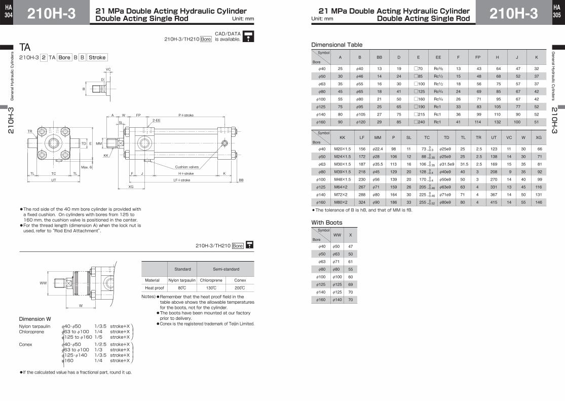
TA210H-3 2 TA
B
VC
E
Max. 6
TD
UT
TCTL TL
2-EE
TR
KK
MM
Cushion valves
H+stroke
LF+stroke
P+stroke
BB
K
XG
F J
W FPA
D
SL
WW
W
210H-3/TH210 Bore
Bore B B Stroke
f40・f50 1/3.5 stroke+Xf63 to f100 1/4 stroke+Xf125 to f160 1/5 stroke+X
f40・f50 1/2.5 stroke+Xf63 to f100 1/3 stroke+Xf125・f140 1/3.5 stroke+Xf160 1/4 stroke+X
⎞⎟⎠⎞⎟⎟⎠
⎞⎟
⎠⎞
⎟⎟
⎠
Standard Semi-standard
Material
Heat proof
Chloroprene Conex
80℃ 130℃ 200℃
Notes)●Remember that the heat proof field in the table above shows the allowable temperatures for the boots, not for the cylinder.●The boots have been mounted at our factory prior to delivery.●Conex is the registered trademark of Teijin Limited.
●The rod side of the 40 mm bore cylinder is provided with a fixed cushion. On cylinders with bores from 125 to 160 mm, the cushion valve is positioned in the center.●For the thread length (dimension A) when the lock nut is used, refer to “Rod End Attachment”.
Dimension WNylon tarpaulinChloroprene
Conex
●If the calculated value has a fractional part, round it up.
Nylon tarpaulin
f40
f50
f63
f80
f100
f125
f140
f160
f40
f50
f63
f80
f100
f125
f140
f160
With Boots
Dimensional Table
f40
f50
f63
f80
f100
f125
f140
f160
f50
f63
f71
f80
f100
f125
f125
f140
WW
47
50
61
55
60
69
70
70
X
E
□70
□85
□100
□125
□160
□190
□215
□240
F
13
15
18
24
26
33
36
41
H
64
68
75
85
95
105
110
132
J
47
52
57
67
67
77
90
100
A
25
30
35
45
55
75
80
90
B
f40
f46
f55
f65
f80
f95
f105
f120
BB
13
14
16
18
21
25
27
29
D
19
24
30
41
50
65
75
85
EE
Rc3/8
Rc1/2
Rc1/2
Rc3/4
Rc3/4
Rc1
Rc1
Rc1
FP
43
48
56
69
71
83
99
114
K
32
37
37
42
42
52
52
51
KK
M20×1.5
M24×1.5
M30×1.5
M39×1.5
M48×1.5
M64×2
M72×2
M80×2
LF
156
172
187
218
230
267
288
324
MM
f22.4
f28
f35.5
f45
f56
f71
f80
f90
TD
f25e9
f25e9
f31.5e9
f40e9
f50e9
f63e9
f71e9
f80e9
TL
25
25
31.5
40
50
63
71
80
TR
2.5
2.5
2.5
3
3
4
4
4
VC
11
14
15
9
14
13
14
14
XG
66
71
81
92
99
116
131
146
TC
73
88
106
128
170
205
225
255
0–0.3
0–0.35
0–0.35
0–0.4
0–0.4
0–0.46
0–0.46
0–0.52
UT
123
138
169
208
270
331
367
415
P
98
106
113
129
139
159
164
186
W
30
30
35
35
40
45
50
55
SL
11
12
16
20
20
26
30
33
The tolerance of B is h8, and that of MM is f8.
Symbol
Bore
Symbol
Bore
Symbol
Bore
CAD/DATAis available.210H-3/TH210 Bore
21 MPa Double Acting Hydraulic CylinderDouble Acting Single Rod210H-3306
HA210H-3 General Hydraulic Cylinders
21 MPa Double Acting Hydraulic CylinderDouble Acting Single Rod 210H-3 307
HAGeneral H
ydraulic Cylinders
210H-3
Unit: mm Unit: mm
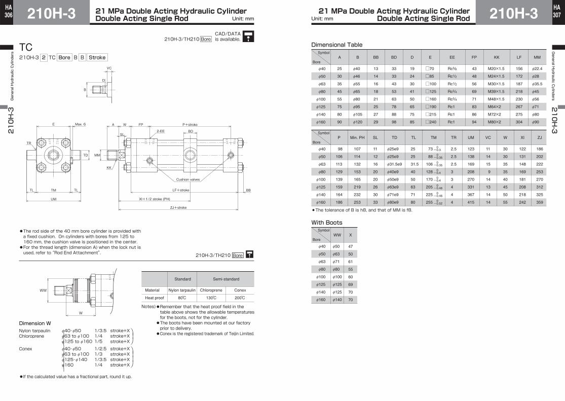
TC210H-3 2 TC
TD
2-EE
KK
Cushion valves
P+stroke
LF+stroke BB
XI+1/2 stroke (PH)
ZJ+stroke
FPWA
BD
UM
TM
B
VC
E
TR
TL TL
MM
Max. 6
D
SL
WW
W
Bore B B Stroke
f40・f50 1/3.5 stroke+Xf63 to f100 1/4 stroke+Xf125 to f160 1/5 stroke+X
f40・f50 1/2.5 stroke+Xf63 to f100 1/3 stroke+Xf125・f140 1/3.5 stroke+Xf160 1/4 stroke+X
⎞⎟⎠⎞⎟⎟⎠
⎞⎟
⎠⎞
⎟⎟
⎠
Standard Semi-standard
Material
Heat proof
Chloroprene Conex
80℃ 130℃ 200℃
Notes)●Remember that the heat proof field in the table above shows the allowable temperatures for the boots, not for the cylinder.●The boots have been mounted at our factory prior to delivery.●Conex is the registered trademark of Teijin Limited.
●The rod side of the 40 mm bore cylinder is provided with a fixed cushion. On cylinders with bores from 125 to 160 mm, the cushion valve is positioned in the center.●For the thread length (dimension A) when the lock nut is used, refer to “Rod End Attachment”.
Dimension WNylon tarpaulinChloroprene
Conex
●If the calculated value has a fractional part, round it up.
Nylon tarpaulin
210H-3/TH210 Bore
With Boots
f40
f50
f63
f80
f100
f125
f140
f160
f50
f63
f71
f80
f100
f125
f125
f140
WW
47
50
61
55
60
69
70
70
X
f40
f50
f63
f80
f100
f125
f140
f160
A
25
30
35
45
55
75
80
90
B
f40
f46
f55
f65
f80
f95
f105
f120
BB
13
14
16
18
21
25
27
29
BD
33
33
43
53
63
78
88
98
D
19
24
30
41
50
65
75
85
E
□70
□85
□100
□125
□160
□190
□215
□240
EE
Rc3/8
Rc1/2
Rc1/2
Rc3/4
Rc3/4
Rc1
Rc1
Rc1
FP
43
48
56
69
71
83
86
94
KK
M20×1.5
M24×1.5
M30×1.5
M39×1.5
M48×1.5
M64×2
M72×2
M80×2
LF
156
172
187
218
230
267
275
304
MM
f22.4
f28
f35.5
f45
f56
f71
f80
f90
f40
f50
f63
f80
f100
f125
f140
f160
P
98
106
113
129
139
159
164
186
Min. PH
107
114
132
153
165
219
232
253
TL
25
25
31.5
40
50
63
71
80
TD
f25e9
f25e9
f31.5e9
f40e9
f50e9
f63e9
f71e9
f80e9
TR
2.5
2.5
2.5
3
3
4
4
4
UM
123
138
169
208
270
331
367
415
VC
11
14
15
9
14
13
14
14
W
30
30
35
35
40
45
50
55
XI
122
131
148
169
181
208
218
242
ZJ
186
202
222
253
270
312
325
359
Dimensional Table
0-0.3
0-0.4
0-0.4
0-0.46
0-0.46
0-0.52
TM
73
88
106
128
170
205
225
255
0-0.35
0-0.35
SL
11
12
16
20
20
26
30
33
The tolerance of B is h8, and that of MM is f8.
Symbol
Bore
Symbol
Bore
Symbol
Bore
CAD/DATAis available.210H-3/TH210 Bore

210H-3210H-3 General Hydraulic Cylinders
308HA
210H-3General H
ydraulic Cylinders
210H-3
309HA
21 MPa Double Acting Hydraulic Cylinder21 MPa Double Acting Hydraulic Cylinder Unit: mm Unit: mm
Rod End Attachment●Rod eye (T-end)
●Rod clevis (Y-end) with pin
f40・f63・f80
Note) The retainer of the 80 mm bore cylinder is located in the same position as that of cylinders with bores from 100 to 160 mm.
●Delivery of rod end attachment (T-end or Y-end)
①When the lock nut and rod end attachment are additionally orderedThe rod end attachment and lock nut are temporarily assembled to the piston rod for delivery. Since the lock nut is not tightened, tighten it after adjusting the position of the rod end attachment.No hex. screw is supplied.
②When only the rod end attachment is additionally ordered (without lock nut)The rod end attachment is tightened to the piston rod, and a drill hole is made on the piston rod for delivery.If the drill hole is unnecessary, give us such instructions.
Hex. screw
KK
CD
FW
CF
RF
JRA
45°
ER
CCCA
Hex. screw
Retainer mounting CBT
Retainer
KK
Width across flatsD
RA
CF
ER
CACC
CD
CFCP CT FW
CW
CV
CW
Retainer
Retainer mounting CBT
KK
Hex. screw
CD
CP
CF
RAJ
CT FW
CW
CV
CW
RF
CCCAER
45° KK
Hex. screw
Retainer
Retainer mounting bolt
ER CA
J
CC
CF
RA
CD RF
45°
CP CT FW
CW
CV
CW
Hex. screw is not supplied.Tapped hole only.Rod end attachment
Rod end attachment
Drilled
Hex. screw (full dog point)
Piston rod
Piston rodLock nut
f40
f50
f63
f80
f100
f125
f140
f160
Part number
部品形式
RTH-20-1-H
RTH-24-2-H
RTH-30-1-H
RTH-39-1-H
RTH-48-1-H
RTH-64-2-H
RTH-72-2-H
RTH-80-2-H
CA
70
85
115
145
180
225
240
280
CC
28
35
43
55
65
85
90
100
CD
f20H10
f25H10
f31.5H10
f40H10
f50H10
f63H10
f71H10
f80H10
CF
f49
f55
f62
f79
f100
f130
f140
f160
ER
25
30
35
40
50
65
70
80
FW
31.5
35.5
40
50
63
80
80
100
J
10
12
15
20
30
40
45
50
KK
M20×1.5
M24×1.5
M30×1.5
M39×1.5
M48×1.5
M64×2
M72×2
M80×2
RA
95
115
150
185
230
290
310
360
RF
32
35
47
62
77
82
97
112
f40
f50
f63
f80
f100
f125
f140
f160
CA
70
85
115
145
180
225
240
280
Part number
RYH-20-1-H
RYH-24-2-H
RYH-30-H
RYH-39-1-H
RYH-48-1-H
RYH-64-2-H
RYH-72-2-H
RYH-80-2-H
CC
32
45
50
60
70
90
100
110
CD
f20
f25
f31.5
f40
f50
f63
f71
f80
CF
40
50
60
80
100
120
140
160
CP
76.5
84.5
93
117
143
183
183
210
CT
63.5
71.5
80
100
126
160
160
180
CW
16
18
20
25
31.5
40
40
40
CV
8
8
8
12
12
18
18
24
D
41
—
60
80
—
—
—
—
ER
R20
25
R30
R40
50
65
70
80
FW
31.5
35.5
40
50
63
80
80
100
J
—
12
—
—
30
30
40
40
KK
M20×1.5
M24×1.5
M30×1.5
M39×1.5
M48×1.5
M64×2
M72×2
M80×2
RA
90
110
145
185
230
290
310
360
RF
—
35
—
—
77
82
97
112
H10f8
H10f8H10f8
H10f8
H10f8
H10f8
H10f8
H10f8
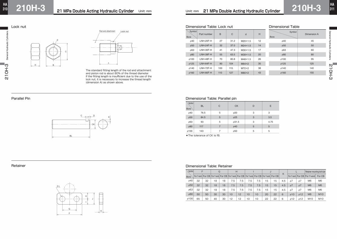
Dimensional Table: Rod eye (T-end)
Dimensional Table: Rod clevis (Y-end) with pin
-0.1-0.4
-0.1-0.4
-0.1-0.4
-0.1-0.6
-0.1-0.6
-0.1-0.6
-0.1-0.4
-0.1-0.4
+0.4+0.1
+0.4+0.1
+0.4+0.1
+0.6+0.1
+0.6+0.1
+0.6+0.1
+0.4+0.1
+0.4+0.1
Symbol
Bore
Symbol
Bore
CAD/DATAis available.210H-3/TH210 Bore
210H-3210H-3 General Hydraulic Cylinders
310HA
210H-3General H
ydraulic Cylinders
210H-3
311HA
21 MPa Double Acting Hydraulic Cylinder21 MPa Double Acting Hydraulic Cylinder Unit: mm Unit: mm
Parallel Pin
Retainer
The standard fitting length of the rod end attachment and piston rod is about 80% of the thread diameter. If the fitting length is insufficient due to the use of the lock nut, it is necessary to increase the thread length (dimension A) as shown above.
Lock nut
H B
C
d
Lock nutRod end attachment
A
C DE
BL
CK
2-L
F
G
H
IJ
K
Dimensional Table: Parallel pin
f40
f50
f63
f80
f100
BL
76.5
84.5
93
117
143
C
5
5
5
7
7
CK
f20
f25
f31.5
f40
f50
D
3
3
3
5
5
E
3
3.5
4.75
5
5
The tolerance of CK is f8.
f40
f50
f63
f80
f100
f125
f140
f160
Part number
LNH-20F-H
LNH-24F-H
LNH-30F-H
LNH-39F-H
LNH-48F-H
LNH-64F-H
LNH-72F-H
LNH-80F-H
d
M20×1.5
M24×1.5
M30×1.5
M39×1.5
M48×1.5
M64×2
M72×2
M80×2
B
27
32
41
55
70
90
100
110
C
31.2
37.0
47.3
63.5
80.8
104
115
127
H
12
14
17
20
26
35
38
43
Symbol
Bore
f40
f50
f63
f80
f100
f125
f140
f160
Dimension A
45
50
60
80
95
125
140
155
Dimensional Table: Lock nut Dimensional Table
f40
f50
f63
f80
f100
F
32
32
32
50
65
32
32
32
50
50
G
18
18
18
30
40
18
18
18
30
30
H
7.5
7.5
7.5
10
12
7.5
7.5
7.5
12
12
7.5
7.5
7.5
10
10
7.5
7.5
7.5
10
10
I J
For Y-end For CB For Y-end For CB For Y-end For CB For Y-end For CBFor Y-end For CBFor Y-end For CBFor Y-end For CB
15
15
15
20
22
15
15
15
22
22
L
f7
f7
f7
f10
f12
f7
f7
f7
f12
f12
K
4.5
4.5
4.5
6
6
Retainer mounting bolt size
M6
M6
M6
M8
M10
M6
M6
M6
M10
M10
Dimensional Table: Retainer
Symbol
Bore
Symbol
Bore
Symbol
Bore
21 MPa Double Acting Hydraulic Cylinder210H-3210H-3 General Hydraulic Cylinders
312HA
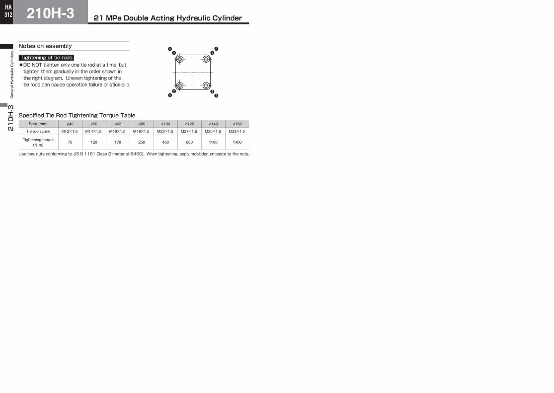
M12×1.5
70Tightening torque
(N・m)
Tie rod screw
Notes on assembly
Tightening of tie rods●DO NOT tighten only one tie rod at a time, but tighten them gradually in the order shown in the right diagram. Uneven tightening of the tie rods can cause operation failure or stick-slip.
Specified Tie Rod Tightening Torque TableBore (mm) f40
M14×1.5
120
f50
M16×1.5
170
f63
M18×1.5
250
f80
M22×1.5
460
f100
M27×1.5
880
f125
M30×1.5
1100
f140
M33×1.5
1400
f160
Use hex. nuts conforming to JIS B 1181 Class 2 (material: S45C). When tightening, apply molybdenum paste to the nuts.
❶
❷
❸
❹❺
❻
❼
❽


![Valve terminal MPA-S - Festo USA · Pneumatic components description Valveterminalwith MPA-Spneumatics Type: MPA-FB MPA-CPI MPA-MPM-…and MPA-ASI-… 534241 1309f [8028624] Valve](https://static.fdocuments.in/doc/165x107/5c5bd85409d3f236368c6efe/valve-terminal-mpa-s-festo-usa-pneumatic-components-description-valveterminalwith.jpg)