H3C SecPath F5000-A5 Firewall Installation Manualh20628. · About This Manual Organization H3C...
158
H3C SecPath F5000-A5 Firewall Installation Manual Hangzhou H3C Technologies Co., Ltd. http://www.h3c.com Manual Version: 5PW101-20090424
Transcript of H3C SecPath F5000-A5 Firewall Installation Manualh20628. · About This Manual Organization H3C...

H3C SecPath F5000-A5 Firewall
Installation Manual
Hangzhou H3C Technologies Co., Ltd.
http://www.h3c.com
Manual Version: 5PW101-20090424

Copyright © 2008-2009, Hangzhou H3C Technologies Co., Ltd. and its licensors
All Rights Reserved
No part of this manual may be reproduced or transmitted in any form or by any means without prior written consent of Hangzhou H3C Technologies Co., Ltd.
Trademarks
H3C, , Aolynk, , H3Care,
, TOP G, , IRF, NetPilot, Neocean, NeoVTL, SecPro, SecPoint, SecEngine, SecPath, Comware, Secware, Storware, NQA, VVG, V2G, VnG, PSPT, XGbus, N-Bus, TiGem, InnoVision and HUASAN are trademarks of Hangzhou H3C Technologies Co., Ltd.
All other trademarks that may be mentioned in this manual are the property of their respective owners.
Notice
The information in this document is subject to change without notice. Every effort has been made in the preparation of this document to ensure accuracy of the contents, but all statements, information, and recommendations in this document do not constitute the warranty of any kind, express or implied.
Technical Support
http://www.h3c.com

About This Manual
Organization
H3C SecPath F5000-A5 Firewall Installation Manual is organized as follows:
Chapter Contents
1 Firewall Overview Briefly introduces the product specifications, as well as the features and applications of the H3C SecPath F5000-A5.
2 Arranging Slots and Numbering Interfaces Introduces the slots and numbering rules of the H3C SecPath F5000-A5.
3 Preparing for Installation Describes the requirements on installation site, the safety recommendations before and during installation, and the required tools.
4 Installing the Firewall Introduces how to install the F5000-A5, as well as how to connect the power cable, console cable, and Ethernet cable.
5 Starting and Configuring the Firewall
Helps you get familiar with the basic knowledge of how to boot and configure the F5000-A5, including device startup, power-on, and initialization of system files, and so on.
6 Maintaining Software Introduces how to maintain the software of the F5000-A5, including upgrading the software and configuration files.
7 Maintaining Hardware Introduces how to maintain the hardware of the F5000-A5.
8 Troubleshooting Describes some problems that may occur during installation and startup of the firewall and how to solve them.
9 Appendix
Provides the details of regulatory compliance information and the safety information in Chinese, comprising general warning, warnings on installation, and safety with electricity.
Conventions
The manual uses the following conventions:
Command conventions
Convention Description
Boldface The keywords of a command line are in Boldface.
italic Command arguments are in italic.
[ ] Items (keywords or arguments) in square brackets [ ] are optional.
x | y | ... Alternative items are grouped in braces and separated by vertical bars. One is selected.
[ x | y | ... ] Optional alternative items are grouped in square brackets and separated by vertical bars. One or none is selected.

Convention Description
x | y | ... * Alternative items are grouped in braces and separated by vertical bars. A minimum of one or a maximum of all can be selected.
[ x | y | ... ] * Optional alternative items are grouped in square brackets and separated by vertical bars. Many or none can be selected.
&<1-n> The argument(s) before the ampersand (&) sign can be entered 1 to n times.
# A line starting with the # sign is comments.
GUI conventions
Convention Description
< > Button names are inside angle brackets. For example, click <OK>.
[ ] Window names, menu items, data table and field names are inside square brackets. For example, pop up the [New User] window.
/ Multi-level menus are separated by forward slashes. For example, [File/Create/Folder].
Symbols
Convention Description
Means reader be extremely careful. Improper operation may cause bodily injury.
Means reader be careful. Improper operation may cause data loss or damage to equipment.
Means an action or information that needs special attention to ensure successful configuration or good performance.
Means a complementary description.
Means techniques helpful for you to make configuration with ease.
Related Documentation
In addition to this manual, each H3C SecPath F5000-A5 Firewall documentation set includes the following:
Manual Description
H3C SecPath Series Security Products User Manual
Describes the features, working principles, and configuration and operation instruction of the H3C SecPath series security products. It guides you through configuring and operating the SecPath series products through Web interfaces and configuring some functions through the CLI.

Obtaining Documentation
You can access the most up-to-date H3C product documentation on the World Wide Web at this URL: http://www.h3c.com.
The following are the columns from which you can obtain different categories of product documentation:
[Products & Solutions]: Provides information about products and technologies, as well as solutions.
[Technical Support & Document > Technical Documents]: Provides several categories of product documentation, such as installation, configuration, and maintenance.
[Technical Support & Document > Software Download]: Provides the documentation released with the software version.
Documentation Feedback
You can e-mail your comments about product documentation to [email protected].
We appreciate your comments.
Environmental Protection
This product has been designed to comply with the requirements on environmental protection. For the proper storage, use and disposal of this product, national laws and regulations must be observed.

i
Table of Contents
1 Firewall Overview ······································································································································1-1 Introduction ·············································································································································1-1 Physical Description································································································································1-2
Front View ·······································································································································1-2 Rear View ········································································································································1-3
System Specifications·····························································································································1-4 MPU–NSQ1MPUA0 ························································································································1-4 LPU–NSQ1GT8C40 ························································································································1-7 LPU–NSQ1XP20·····························································································································1-9 Dimensions and Weight·················································································································1-10 Voltage and Current ······················································································································1-10 Fan Tray ········································································································································1-11 Operating Environment··················································································································1-11
Components··········································································································································1-11 MPU–NSQ1MPUA0 ······················································································································1-11 LPU–NSQ1GT8C40 ······················································································································1-17 LPU–NSQ1XP20···························································································································1-22 Power Supply Module····················································································································1-23 Port Lightning Arrester (Optional)··································································································1-25 Power Lightning Arrester (Optional) ······························································································1-25 Signal Lightning Arrester (Optional) ······························································································1-26 System Software ···························································································································1-26
1-1
1 Firewall Overview
Introduction
The H3C SecPath F5000-A5 firewall (hereinafter referred to as the F5000-A5) is a high-end core firewall product developed by Hangzhou H3C Technologies Co., Ltd. (hereinafter referred to as H3C) to deliver extremely high-performance security solutions for large-sized enterprises, carriers and data center networks.
The F5000-A5 delivers the following features based on its powerful multi-core processor and FPGA-based hardware acceleration technologies:
Adopts dual-power input, passive backplane, switch architecture, and distributed modular architecture.
Separates the control plane from the data plane: At the control plane, a powerful multi-core processor is used for service scheduling and application identification. At the data plane, a dedicated field programmable gate array (FPGA) is used for rapid forwarding of data streams. Moreover, additional service cards can be used to expand the process capability at the data plane.
In addition to traditional firewall functions, the F5000-A5 supports virtual firewall, attack defense, and content filtering, thus delivering more effective network protection.
Uses the application specific packet filter (ASPF) status detection technology to monitor connection processes, detect illegal operations, and implement dynamic packet filtering with ACLs.
Supports server load balancing and link load balancing functions. Supports high-performance virtual private network (VPN) services, such as IPSec VPN, GRE, and
L2TP. Provides abundant routing capabilities and supports multiple routing protocols including Routing
Information Protocol (RIP), Open Shortest Path First (OSPF), and Border Gateway Protocol (BGP).
Supports Web-based configuration and management. Collects and conducts statistics of audit information such as NAT and security events through
H3C’s audit systems (e.g. SecCenter, Xlog, and QuidView). Conforms to both international and national standards to ensure interoperability with products of
different manufacturers at every layer.

1-2
Physical Description
Front View
Figure 1-1 Front view of the F5000-A5
(1) (2) (3)
(7) (5)(8)(9)(10)
(13)
(6)
(15)
(14)
(12)
(11)
(4) (1) Left mounting bracket (2) Main processing unit (MPU) (3) Right mounting bracket (4) Chassis handle (5) Weight-bearing warning label (50 kg/110.2 lb.) (6) Fan tray
(7) AC power module (PWR1) (8) Blank panel for PoE PSU (reserved PoE slot)
(9) Blank panel for DC power module (PWR2) (10) ESD socket and silkscreen (11) Blank panel for LPU (Slot 4) (12) Blank panel for LPU (Slot 3) (13) Blank panel for LPU (Slot 2) (14) Blank panel for LPU (Slot 1) (15) Cable management bracket
Currently, the device does not support power over Ethernet (PoE).

1-3
Rear View
Figure 1-2 Rear view of the F5000-A5
(2)
(1)
(4)
(6)
(7)(8)(9)
(3)
(5)
(1) Warning label (2) Handle on the rear chassis panel (3) Upper slide rail for the air filter (optional) (4) Air filter (optional) (5) Lower slide rail for the air filter (optional) (6) Chassis handle (7) Weight-bearing warning label (50 kg/110.2 lb.) (8) Grounding screw and sign (9) Vents
Do not hold the handle indicated by (2) in Figure 1-2 on the rear chassis panel to move the chassis because it is designed for the convenience of the rear chassis panel removal, but not for bearing the chassis weight.

1-4
System Specifications
MPU–NSQ1MPUA0
Front view
Figure 1-3 Front view of the MPU
(1) Link status LED of the management Ethernet port (LINK)
(2) Data reception/transmission LED of the management Ethernet port (ACT)
(3) Link status LED of the HA port (LINK) (4) Data reception/transmission LED of the HA port (ACT)
(5) CF card eject button (CF CARD) (6) CF card slot (7) CF card LED (CF) (8) Run LED (RUN) (9) Active LED of the MPU (ACT) (10) Alarm LED (ALM) (11) Reset button (RESET) (12) USB interface 1 LED (USB1) (13) USB interface 1 (1) (14) USB interface 0 (0) (15) AUX port (AUX) (16) Console port (CONSOLE)
(17) HA port-10/100/1000BASE-T (HA) (18) Management Ethernet port-10/100/1000BASE-T (MANAGEMENT)
(19) Ejector lever (20) Captive screw
Currently, the device supports only one MPU and the MPU must be inserted in Slot 0.
Technical specifications
Table 1-1 Technical specifications of the MPU
Item Specification
Processor RMI XLR732 1 GHz
Processor cores 8
Flash 4 MB
Memory type and size
DDR2 SDRAM 2 memory slots 2 GB (default) Memory modules must be used in pairs with the same size.
Console port 1 (9600 bps to 115200 bps, 9600 bps by default)

1-5
Item Specification
AUX port 1 (9600 bps to 115200 bps, 9600 bps by default)
Management Ethernet port 1 (10Base-T/100Base-TX/1000Base-T)
HA port 1 (10Base-T/100Base-TX/1000Base-T)
CF card 256 MB by default for the built-in CF card 256 MB, 512 MB, or 1 GB for an optional external CF card
USB interfaces 2 (USB 0: operating in the host mode; USB 1: operating in the device mode) Reserved for future use
Reset button 1
The flash is used for storing the boot file—the BootWare program. The memory is used for storing system data during operation and caching data in data forwarding. A CF card is used for storing the software system and configuration files of the device.
LEDs
Figure 1-4 LEDs on the MPU
(1)(2)
(3)(4)
(5)
(9)
(6)(7)(8)
(1) Link status LED of the management Ethernet port (LINK)
(2) Data reception/transmission LED of the management Ethernet port (ACT)
(3) Link status LED of the HA port (LINK) (4) Data reception/transmission LED of the HA port (ACT)
(5) CF card LED (CF) (6) Run LED (RUN) (7) Data reception/transmission LED of the management Ethernet port/HA port (ACT) (8) Alarm LED (ALM) (9) USB interface 1 LED
1) Device status LEDs

1-6
Table 1-2 Description of the device status LEDs
LED Status Description
OFF No power input or the MPU is faulty.
Slow blinking (1 Hz) The MPU is operating normally.
Fast blinking (8 Hz) The application software is being loaded (in this state, never power off the device or hot-swap the MPU; otherwise the MPU may be damaged), or the MPU is not working.
RUN (green)
Reset The RUN LED goes off after the system is reset and flashes fast on system startup.
OFF The MPU is in the standby state or there is no power input. ACT (yellow)
ON The MPU is in the active state.
OFF The system is operating normally with no alarms.
ON A fault has occurred to the system. In this state, check the system log immediately. ALM (red)
Fast blinking (8 Hz) A critical fault has occurred to the system. In this state, handle the fault immediately.
2) Management Ethernet port/HA port LEDs
Table 1-3 Description of the management Ethernet port/HA port LEDs
LED Status Description
OFF No link is present on the port. LINK (green)
ON A link is present on the port.
OFF No data is being transmitted or received on the port. ACT (yellow)
ON Data is being transmitted or received on the port.
3) USB interface LED
Table 1-4 Description of the USB interface LED
LED Status Description
OFF No host is connected to the device-mode USB interface.
ON A host is in connection with the device-mode USB interface. The USB cable can be unplugged in this state. USB (green)
Blinking Data is being transmitted or received through the device-mode USB interface. Do not unplug the USB cable in this state.
USB interfaces are reserved for future use.

1-7
4) CF card LED
Table 1-5 Description of the CF card LED
LED Status Description
OFF No CF card is present or the CF card is not recognizable.
ON A CF card is in position and has been detected. CF (green)
Blinking The system is accessing the CF card. Do not remove the CF card in this state.
Do not remove the CF card when the CF LED is blinking. Otherwise, the files stored on the CF card will be damaged.
LPU–NSQ1GT8C40
Introduction
An NSQ1GT8C40 line processing unit (LPU) provides eight electrical interfaces and four Combo interfaces, delivering high-speed service process capabilities. Note that:
An NSQ1GT8C40 LPU can be inserted in slot 1, 2, 3, or 4 of the F5000-A5. An F5000-A5 needs to be equipped with an MPU and at least one LPU to work normally.
Figure 1-5 Front view of NSQ1GT8C40
(1) GE interface 1 (2) GE interface 3 (3) GE interface 5 (4) GE interface 7 (5) GE interface 9 (6) SFP interface 9 (7) SFP interface 9 LED (SFP9) (8) SFP interface 8 LED (SFP8) (9) GE interface 11 (10) SFP interface 11 (11) SFP interface 11 LED (SFP11) (12) SFP interface 10 LED (SFP10) (13) LPU LED (RUN) (14) SFP interface 10 (15) GE interface 10 (16) SFP interface 8 (17) GE interface 8 (18) GE interface 6 (19) GE interface 4 (20) GE interface 2 (21) GE interface 0 (22) Eject lever (23) Captive screw

1-8
Technical specifications
Table 1-6 Technical specifications of NSQ1GT8C40
Item Description
Memory type and size DDR2 SDRAM 1 memory slot 512 MB (default), 1 GB (maximum)
8
10 Mbps, half/full duplex
100 Mbps, half/full duplex Electrical interfaces
1000 Mbps, full duplex
4 (electrical/optical)
10 Mbps, half/full duplex
100 Mbps, half/full duplex Electrical interfaces
1000 Mbps, full duplex
Combo interfaces
Optical interfaces 1000 Mbps, full duplex
Power consumption monitoring Supported
A Combo interface is comprised of an electrical interface and a small form-factor pluggable (SFP) interface.
For an optical/electrical Combo interface, the default operating interface is the electrical interface. For a Combo interface, either the electrical interface or the optical interface can operate at one time.
You can use the combo enable copper | fiber command in interface view to switch between the electrical and optical interfaces. For details about the combo enable copper | fiber command, refer to H3C SecPath Series Security Products User Manual.
LEDs
Table 1-7 Description of the LEDs on NSQ1GT8C40
LED Status Description
OFF No power input or the LPU is faulty.
Slow blinking (1 Hz) The LPU is operating normally.
Fast blinking (8 Hz) The application software is being loaded (in this state, never power off the device or hot-swap the LPU; otherwise the LPU may be damaged), or the LPU is not working.
RUN (green)
Reset The RUN LED goes off after the system is reset and flashes fast on system startup.

1-9
LED Status Description
OFF No link is present on the corresponding interface.
Solid green A 1000 Mbps link is present on the interface.
Blinking green Data is being transmitted or received at 1000 Mbps.
Solid yellow A 10/100 Mbps link is present on the interface.
GE0 through GE11 (yellow/green)
Blinking yellow Data is being transmitted or received at 10/100 Mbps.
OFF No fiber link is present on the interface.
Solid green A fiber link is present on the interface.
Blinking green Data is being transmitted or received at 1000 Mbps.
SFP8 through SFP11 (yellow/green)
Solid yellow The optical module fails to be detected.
LPU–NSQ1XP20
Introduction
An NSQ1XP20 provides two Ten-gigabit small form-factor pluggable (XFP) interfaces, delivering high-speed service process capabilities. The front panel of the LPU provides one LED for each interface. Currently, this LPU supports only the LAN PHY mode, but not the WAN PHY mode. Note that:
NSQ1XP20 can be inserted in slot 1, 2, 3, or 4 of the F5000-A5. The F5000-A5 needs to be equipped with an MPU and at least one LPU to work normally.
Figure 1-6 Front view of NSQ1XP20
(1) Captive screw (2) Eject lever (3) XFP interface 0 (4) XFP interface 0 LED (XFP0) (5) XFP interface 1 (6) XFP interface 1 LED (XFP1) (7) LPU LED (RUN)
Technical specifications
Table 1-8 Technical specifications of NSQ1XP20
Item Description
Memory type and size DDR2 SDRAM 1 memory slot 512 MB (default), 1 GB (maximum)
XFP interfaces 2 10GBASE-R
Power consumption monitoring Supported
1-10
LPU LEDs
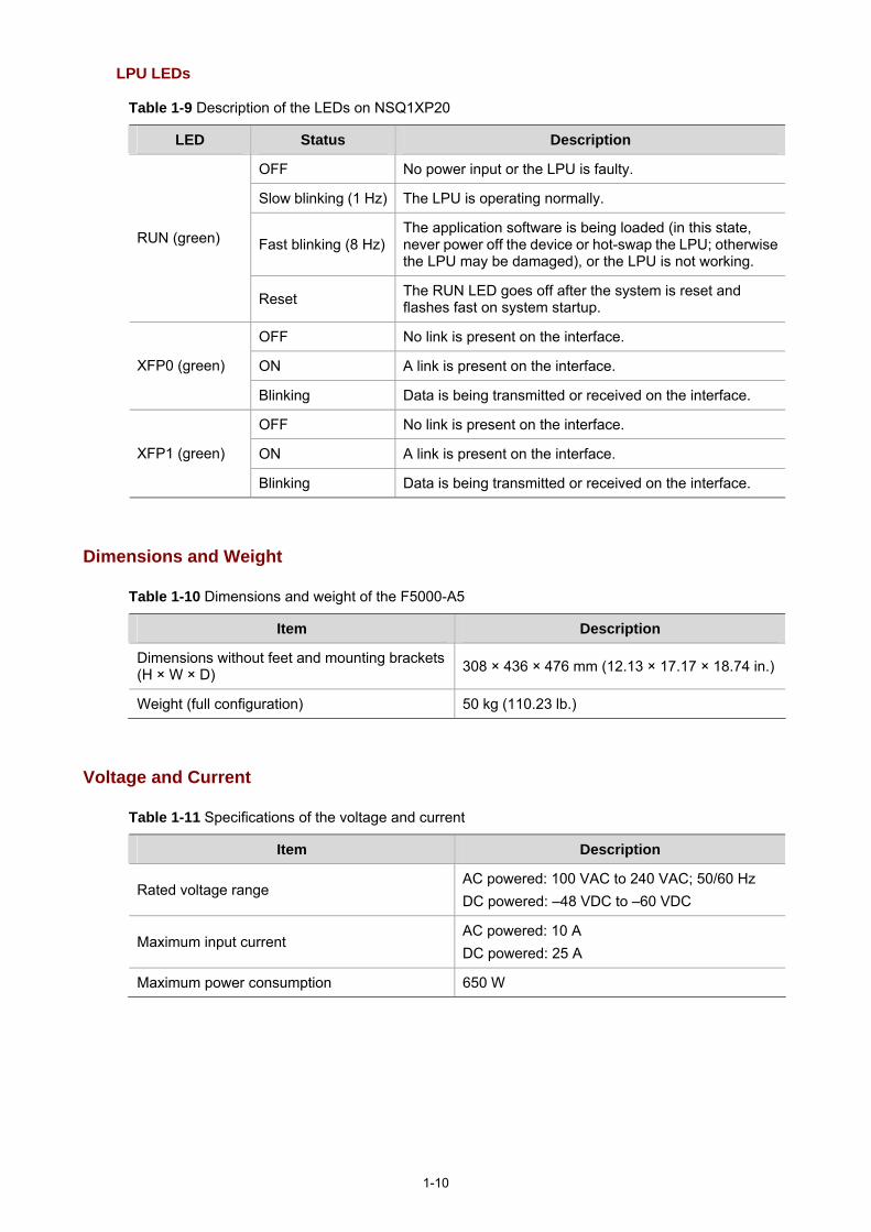
Table 1-9 Description of the LEDs on NSQ1XP20
LED Status Description
OFF No power input or the LPU is faulty.
Slow blinking (1 Hz) The LPU is operating normally.
Fast blinking (8 Hz)The application software is being loaded (in this state, never power off the device or hot-swap the LPU; otherwise the LPU may be damaged), or the LPU is not working.
RUN (green)
Reset The RUN LED goes off after the system is reset and flashes fast on system startup.
OFF No link is present on the interface.
ON A link is present on the interface. XFP0 (green)
Blinking Data is being transmitted or received on the interface.
OFF No link is present on the interface.
ON A link is present on the interface. XFP1 (green)
Blinking Data is being transmitted or received on the interface.
Dimensions and Weight
Table 1-10 Dimensions and weight of the F5000-A5
Item Description
Dimensions without feet and mounting brackets (H × W × D) 308 × 436 × 476 mm (12.13 × 17.17 × 18.74 in.)
Weight (full configuration) 50 kg (110.23 lb.)
Voltage and Current
Table 1-11 Specifications of the voltage and current
Item Description
Rated voltage range AC powered: 100 VAC to 240 VAC; 50/60 Hz DC powered: –48 VDC to –60 VDC
Maximum input current AC powered: 10 A DC powered: 25 A
Maximum power consumption 650 W

1-11
Fan Tray
Table 1-12 Technical specifications of the fan tray
Item Specification
Rated voltage 12 VDC
Total fan power consumption 50 W
Dimensions (H × W × D) 227 × 31 × 413.3 mm (8.94 ×1.22 × 16.27 in.)
Table 1-13 Description of the fan tray LEDs
LED Status Description
RUN (green) ON The fan tray is working normally.
ALM (red) ON The fan tray is faulty.
The F5000-A5 supports automatic fan speed adjustment but not hot-swapping of the fan tray.
Operating Environment
Table 1-14 Operating environment specifications
Item Description
Operating temperature 0°C to 45°C (32°F to 113°F)
Operating humidity 10% to 95%, noncondensing
Altitude –60 m to +4 km (–196.85 ft. to +2.49 miles)
Components
MPU–NSQ1MPUA0
Processor
The NSQ1MPUA0 is an MPU that uses an RMI XLR732 1 GHz processor as the route processing engine.
Flash
The flash size is 4 MB, of which 1 MB is used for storing the boot file—BootWare and the remaining space for BootWare backup and storing important system parameters.

1-12
Memory module
The memory module is used for storing data exchanged between the system and the CPU. The default memory size of the MPU is 2 GB, which is the maximum memory size supported by the MPU. The MPU provides two memory slots for memory modules of the same size.
You can use DDR2 SDRAM-1GB for the MPU of the device.
CF card
1) Introduction
A compact flash (CF) card is used for storing logs, host files, and configuration files.
The F5000-A5 is equipped with a 256 MB built-in CF card, which is identified with cfa0. In addition, the device provides an external CF card slot to extend the local storage space. A CF card inserted into the CF card slot is identified with cfb0.
The CF cards supported by the device are available in three sizes:
256 MB 512 MB 1 GB
Use CF cards provided by H3C only. The device may be incompatible with other CF cards.
2) CF card and slot
Figure 1-7 CF card and the LED
(1) (2) (3)
(1) Eject button (CF CARD) (2) CF card slot (3) CF card LED (CF)
3) CF card LED
For the description of the CF card LED, see Table 1-5.
1-13
The CF card is hot-swappable. When the CF LED is blinking, do not unplug the CF card. Otherwise, the file system on the CF card may be damaged.
Console port
1) Introduction
The F5000-A5 provides an RS232 asynchronous serial console port, which can be connected to a computer for system debugging, configuration, maintenance, management, and host software loading.
2) Technical specifications
Table 1-15 Technical specifications of the console port
Item Description
Connector type RJ-45
Compliant standards RS232
Baud rate 9600 bps to 115200 bps, 9600 bps by default
Maximum transmission distance 15 m (49.21 ft.)
Services
Connection to an ASCII terminal Connection to the serial interface of a local PC to run
the terminal emulation program Command line interface (CLI)
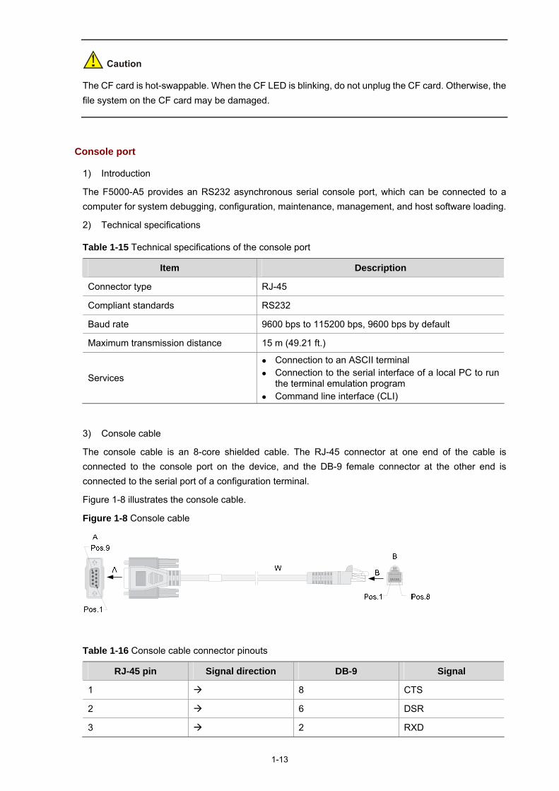
3) Console cable
The console cable is an 8-core shielded cable. The RJ-45 connector at one end of the cable is connected to the console port on the device, and the DB-9 female connector at the other end is connected to the serial port of a configuration terminal.
Figure 1-8 illustrates the console cable.
Figure 1-8 Console cable
Table 1-16 Console cable connector pinouts
RJ-45 pin Signal direction DB-9 Signal
1 8 CTS
2 6 DSR
3 2 RXD

1-14
RJ-45 pin Signal direction DB-9 Signal
4 1 DCD
5 — 5 GND
6 3 TXD
7 4 DTR
8 7 RTS
For the connection of the console cable, refer to the section talking about connecting a console cable in Chapter 4 “Installing the Firewall.”
AUX port
1) Introduction
The AUX port is an RS232 asynchronous serial port used for remote configuration or dialup backup. You need to connect the local modem to the remote modem through the PSTN to reach the remote device for remote system debugging, configuration, maintenance, and management. In case that the console port is faulty, the AUX port can be connected to a terminal as a backup port of the console port. For details, refer to Chapter 8 “Troubleshooting.”
2) Technical specifications
Table 1-17 Technical specifications of the AUX port
Item Description
Connector type RJ-45
Compliant standard RS232
Baud rate 9600 bps to 115200 bps, 9600 bps by default
Service Connection to the serial interface of a remote PC through a pair of modems to establish a dial-up connection with the remote PC
3) AUX cable
The AUX cable is an 8-core shielded cable. The RJ-45 connector at one end of the cable is connected to the AUX port on the firewall, and the DB-25 male connector or DB-9 male connector at the other end is connected to the serial port on a modem as needed.

1-15
Figure 1-9 AUX cable
Table 1-18 AUX cable connector pinouts
RJ-45 Signal direction DB-25 DB-9 Signal
1 4 7 RTS
2 20 4 DTR
3 2 3 TXD
4 8 1 DCD
5 — 7 5 GND
6 3 2 RXD
7 6 6 DSR
8 5 8 CTS
For how to connect the AUX cable, refer to the section talking about connecting the AUX Cable to a modem in Chapter 4 “Installing the Firewall.”
Management Ethernet port/HA port
The management Ethernet port is a 10Base-T/100Base-TX/1000Base-T RJ-45 auto-sensing interface. It allows you to upgrade software and manage the device through a network management server, without using any service interface of the device. The management Ethernet port is only for managing the device and has no service processing capabilities such as data forwarding.
The high availability (HA) feature is mainly delivered through stateful failover and VRRP. The HA port is a 10Base-T/100Base-TX/1000Base-T RJ-45 auto-sensing interface, which is used for synchronizing link state packets in a dual-system network.

1-16
Table 1-19 Technical specifications of the management Ethernet port/HA port
Item Description
Connector type RJ-45
Port quantity 1 management Ethernet port 1 HA port
Interface type Automatic MDI/MDIX
Frame formats Ethernet_II Ethernet_SNAP
Interface speed and duplex mode 10 Mbps, half/full duplex 100 Mbps, half/full duplex 1000 Mbps, full duplex
Maximum transmission distance 100 m (328.08 ft.)
Function Software upgrade and network management
The media dependent interface (MDI) standard is typically used on the Ethernet interface of network adaptors. The media dependent interface crossover (MDI-X) standard is typically used on hubs or LAN switches.
RESET button
The RESET button is used to reset the current MPU. The RUN LED goes off when the MPU is reset, flashes fast (at 8 Hz) when BootWare is running, and flashes slowly (at 1 Hz) after the system is booted and operates normally.
If you perform no save operation before resetting the device, the current system configuration will not be saved.
Never press the RESET button when the device boots up with the RUN LED blinking fast or when the device is accessing the CF card; otherwise, the file system of the device may be damaged.
Clock
The F5000-A5 is designed with an interface clock module, which provides the system time. You can set the system time through the command line interface.
The clock module continues working even if a power failure occurs to the device, ensuring a correct system time next time the device boots. With the device powered off, the clock module can work for at least 10 years.
Note that:

1-17
Never replace the clock module battery when the device is powered on. The system time gets lost once the clock module battery is removed. You need to set the system
time again through the command line interface.
Use the clock datetime time date command in user view to set the system date and time. For details about the clock datetime command, refer to H3C SecPath Series Security Products
User Manual.
LPU–NSQ1GT8C40
Ethernet interface introduction
NSQ1GT8C40 provides eight electrical interfaces (10Base-T/100Base-TX/1000Base-T) and four Combo interfaces. A Combo interface consists of an electrical interface and an optical interface. The default operating interface is the electrical interface.
For the interface speed and duplex mode of electrical interfaces and the Combo interfaces operating in electrical interface mode, see Table 1-20.
Table 1-20 Interface speed and duplex mode of electrical interfaces
Interface speed Duplex mode
10 Mbps auto-sensing Half/full duplex
100 Mbps auto-sensing Half/full duplex
1000 Mbps auto-sensing Full duplex
The electrical interface LEDs are above the RJ-45 ports. The LEDs in triangle and inverted triangle indicate the status of the lower and upper electrical Ethernet interfaces respectively. For the description of the electrical interface LEDs, refer to Table 1-7.
The optical interface of a Combo interface supports 1000 Mbps in full duplex mode. It has an interface LED on the right of the optical interface, indicating the status of the SFP optical interface. For the description of the optical interface LEDs, refer to Table 1-7.
For a Combo interface, either the electrical interface or the optical interface can operate at one time. You can use the combo enable copper | fiber command in interface view to switch between the electrical and optical interfaces. For details about the combo enable copper | fiber command, refer to H3C SecPath Series Security Products User Manual.

1-18
Technical specifications for Ethernet interfaces
Technical specifications for electrical Ethernet interfaces
Table 1-21 Technical specifications for electrical Ethernet interfaces
Item Description
Connector type RJ-45
Interface type Automatic MDI/MDIX
Frame formats Ethernet_II Ethernet_SNAP
10 Mbps, half/full duplex
100 Mbps, half/full duplex Interface speed and duplex mode
1000 Mbps, full duplex
When 10/100 Mbps and half/full duplex mode are specified for an electrical Ethernet interface, the electrical Ethernet interface operates in the forced mode. When 1000 Mbps or the speed and the duplex mode are not simultaneously specified for an electrical Ethernet interface, the electrical Ethernet interface operates in the auto-negotiation mode.
No matter whether an electrical Ethernet interface operates in the forced or auto-negotiation mode, it supports automatic MDI/MDIX.
Technical specifications for optical Ethernet interfaces
Table 1-22 Technical specifications for GE optical interfaces
Item Description
Connector type SFP/LC
Compliant standards 802.3, 802.3u, and 802.3ab
Type
Short-haul multimode optical interface module (850 nm)
Medium-haul single-mode optical interface module (1310 nm)
Long-haul optical interface module (1310 nm)
Long-haul optical interface module (1550 nm)
Ultra-long haul optical interface module (1550 nm)
Min –9.5 dBm –9 dBm –2 dBm –4 dBm –4 dBm
Optical transmit power
Max 0 dBm –3 dBm 5 dBm 1 dBm 2 dBm
Receiving sensitivity –17 dBm –20 dBm –23 dBm –21 dBm –22 dBm
Central wavelength 850 nm 1310 nm 1310 nm 1550 nm 1550 nm

1-19
Item Description
Fiber type
62.5/125 μm multimode fiber
9/125 μm single-mode fiber
9/125 μm single-mode fiber
9/125 μm single-mode fiber
9/125 μm single-mode fiber
Maximum transmission distance
0.55 km (0.34 miles)
10 km (6.21 miles)
40 km (24.86 miles)
40 km (24.86 miles)
70 km (43.50 miles)
Operating mode 1000 Mbps in full duplex mode
RJ-45 connector
The 10Base–T/100Base–TX/1000Base–T electrical Ethernet interfaces of the F5000-A5 use RJ-45 connectors and support automatic MDI/MDI-X. Category-5 twisted pair cables are used for RJ-45 connectors. Figure 1-10 illustrates the RJ-45 connector.
Figure 1-10 RJ-45 connector
LC connector
Optical fiber connectors are indispensable passive components in optical fiber communication system. Their application enables the removable connection between optical channels, which makes the optical system debugging and maintenance more convenient and the transit dispatching of the system more flexible.
Some optical fiber connecter types are as follows:
LC: square optical fiber connector of the push-pull snap-in type SC: standard optical fiber connector FC: round optical fiber connector with screw thread ST: round plug-in optical fiber connector MT-RJ: square transceiver optical fiber connector
Currently, the optical Ethernet interfaces on NSQ1GT8C40 can only use LC connectors.
Figure 1-11 LC connector

1-20
Before using an optical fiber to connect a network device, verify that the optical fiber connector matches the optical module.
Before connecting an optical fiber, make sure the received optical power at the local end does not exceed the upper threshold of the receiving optical power of the optical module. Otherwise, the optical module may be damaged.
Cable connecting electrical Ethernet interfaces
Usually, you can use a Category-5 twisted pair cable to connect an electrical Ethernet interface. Figure 1-12 shows an Ethernet cable.
Figure 1-12 Ethernet cable
Ethernet cables fall into two categories:
Standard cable: Also known as straight-through cable. At both ends of a standard cable, wires are crimped in the RJ-45 connectors in the same sequence. A straight-through cable is used for connecting a terminal (for example, a PC or router) to a hub or LAN switch. The cables delivered with the firewall are straight-through cables.
Crossover cable: At both ends of a crossover cable, wires are crimped in the RJ-45 connectors in different sequences. A crossover cable is used for connecting two terminals (for example, PC or router). You can make crossover cables by yourself as needed.
Table 1-23 Straight-through cable connector pinouts
RJ-45 Signal Category-5 twisted pair Signal direction RJ-45 pin
1 TX+ White (Orange) 1
2 TX– Orange 2
3 RX+ White (Green) 3
4 — Blue — 4
5 — White (Blue) — 5
6 RX– Green 6
7 — White (Brown) — 7
8 — Brown — 8

1-21
Table 1-24 Crossover cable connector pinouts
RJ-45 Signal direction Category-5 twisted pair Signal direction RJ-45
1 TX+ White (Orange) 3
2 TX– Orange 6
3 RX+ White (Green) 1
4 — Blue — 4
5 — White (Blue) — 5
6 RX– Green 2
7 — White (Brown) — 7
8 — Brown — 8
You can refer to the tables above when distinguishing between and preparing these two types of Ethernet cables.
When preparing Ethernet cables, follow the chromatogram given in the table to arrange the wires. Otherwise, communication quality will be affected even if the two devices at both ends can communicate.
When preparing Ethernet cables, use shielded cables preferentially for electromagnetic compatibility.
Fiber connecting optical Ethernet interfaces
You can use a single-mode or multimode fiber to connect a 1000 Mbps optical Ethernet interface and select proper fibers for the installed 1000Base–X SFP optical modules (GE SFP transceivers for short). Because the optical interfaces on these SFP transceivers use LC optical connectors, you must use fibers with LC optical connectors. All SFP transceivers are hot-swappable.
No SFP transceivers are shipped with the F5000-A5. Use only the SFP transceivers provided by H3C. The device cannot recognize other SFP
transceivers. For the connection of electrical Ethernet cables and optical fibers, refer to the section talking about
connecting Ethernet cables in Chapter 4 “Installing the Firewall.”

1-22
LPU–NSQ1XP20
Introduction to 10 GE interfaces
NSQ1XP20 provides two XFP interfaces (10GBASE–R), which operate in the LAN PHY mode rather than the WAN PHY mode. An XFP interface operating in the LAN PHY mode supports a maximum data-rate of 10.3125 Gbps. The LED for an XFP interface is on the right of the interface, indicating the status of the interface. For the description of the XFP interface LEDs, refer to Table 1-9.
Technical specifications for 10 GE interfaces
Table 1-25 Technical specifications of the XFP interfaces
Item Description
Connector type XFP/LC
Physical layer 10GBASE–R
Interface speed LAN PHY mode: 10.3125 Gbps
Type Short-haul multimode Medium-haul single-mode Long-haul single-mode
Min –7.3 dBm –8.2 dBm –1 dBm
Optical transmit power
Max –1.08 dBm 0.5 dBm 2 dBm
Receiving sensitivity –7.5 dBm –10.3 dBm –11.3 dBm
Central wavelength 850 nm 850 nm 1310 nm
Maximum transmission distance 300 m (984.25 ft.) 300 m (984.25 ft.) 10 km (6.21 miles)
Fiber type 62.5/125 μm multimode fiber
9/125 μm single-mode fiber
9/125 μm single-mode fiber
Cable connecting 10 GE interfaces
You can use a single-mode or multimode fiber to connect an XFP interface and select proper fibers for the installed XFP optical modules (XFP transceivers for short). Since the optical interfaces on these XFP transceivers use LC optical connectors, you must use fibers with LC optical connectors. All XFP transceivers are hot-swappable. Figure 1-13 shows an XFP transceiver. For a fiber with LC connectors, see Figure 1-11.

1-23
Figure 1-13 An XFP transceiver
No XFP transceivers are shipped with the F5000-A5. Use only the XFP transceivers provided by H3C. The device cannot recognize other XFP
transceivers. For how to connect XFP transceivers, refer to the section talking about connecting Ethernet cables
in Chapter 4 “Installing the Firewall.”
Power Supply Module
The F5000-A5 supports both AC and DC power input. You can select an AC power module or a DC power module. However, never install the two types of power PSUs in the same device.
The F5000-A5 needs only one PSU for normal operation of the system. But the device provides two slots for 1+1 redundancy.
The PSUs are hot-swappable.
Online insertion and removal of a PSU refers to first switching off the power module and then removing it from the device or inserting it into the device.
AC power module
Table 1-26 lists the specifications for the AC power module of the device.

1-24
Table 1-26 AC power module specifications
Item Specification
Rated voltage range 100 VAC to 240 VAC; 50/60 Hz
Maximum input current 10 A
Maximum power consumption 650 W
Dimensions (H × W × D) 40.2 × 140 × 353.5 mm (1.58 × 5.51 ×13.92 in.)
Table 1-27 Description of the AC power LED
Status Description
OFF No power input is present.
Solid green The power module is working normally.
Solid red The power module is faulty.
Figure 1-14 AC power module
(1) (2) (3) (4)
(5)
(6) (1) Captive screw (2) Bail latch (3) Power socket (4) Power switch (5) Power LED (6) PSU handle
DC power module
Table 1-28 lists the specifications for the DC power module of the device.
Table 1-28 DC power module specifications
Item Specification
Rated voltage range –48 VDC to –60 VDC
Maximum input current 25 A
Maximum power consumption 650 W
Dimensions (H × W × D) 40.2 × 140 × 353.5 mm (1.58 × 5.51 ×13.92 in.)

1-25
Table 1-29 Description of the DC power LED
Status Description
OFF No power input is present.
Solid green The power module is working normally.
Solid red The power module is faulty.
Figure 1-15 DC power module
(1) Captive screw (2) Power input terminals (3) Power switch (4) Power LED (5) Power module handle
Port Lightning Arrester (Optional)
Before connecting an outdoor Ethernet cable to an Ethernet port, install a port lightning arrester to protect the device against lightning strokes.
The following port lightning arrester can be installed on the F5000-A5. The specifications for the port lightning arrester are as follows: Port protective unit–single port, maximum discharge current (8/20μs waveform): 5 kA, output voltage (10/700μs waveform): core-core < 40 V, core-ground < 600 V.
For the installation of a port lightning arrester, refer to Chapter 4 “Installing the Firewall.”
Power Lightning Arrester (Optional)
Before connecting an outdoor AC power cable to the device, you can install a lightning protection busbar at the AC power input end to protect the device against lightning strokes. In a heavy lightning area, you are recommended to install a power lightning arrester.

1-26
The following power lightning arrester can be installed on the F5000-A5. The specifications for the power lightning arrester are as follows: Maximum discharge current: 6500 A, protection voltage: 220 VAC to 500 VAC.
For the installation of a power lightning arrester, refer to Chapter 4 “Installing the Firewall.”
Signal Lightning Arrester (Optional)
Generally, you need to install a signal lightning arrester between a signal cable and the connected device. This can protect electronic devices against surge over-voltage resulting from lightning strokes and other interferences, and minimize impact on the device.
The device supports three types of signal lightning arresters:
Voltage-limiting protection parts–signal lightning arrester–maximum discharge current 2.5KA/protection voltage 25V—SMB-75J/SMB-75J-1W-10Mbps.
Voltage-limiting protection parts–signal lightning arrester–maximum discharge current 2.5KA/protection voltage 25V-BNC-75K/BNC-75K-10Mbps.
Voltage-limiting protection parts–single lightning arrester (U port)-maximum discharge current 3KA/comman mode 400 V/differential mode 170V-RJ11.
For the installation of a signal lightning arrester, refer to Chapter 4 “Installing the Firewall.”
System Software
The F5000-A5 uses the Comware V5 software platform, H3C’s core software platform.
Based on the IPv4/IPv6 dual stack, the Comware V5 software platform integrates link-layer protocols, routing protocols, Multi-Protocol Label Switching (MPLS), virtual private network (VPN), security, and other data communications features. It is scalable and portable because it adopts a componentized architecture and effectively encapsulates and masks different operating systems and hardware.

i
Table of Contents
2 Arranging Slots ands Numbering Interfaces ··························································································2-1 Slot Arrangement ····································································································································2-1 Numbering Interfaces······························································································································2-1 Examples ················································································································································2-2
Numbers of interfaces on NSQ1GT8C40························································································2-2 Numbers of interfaces on NSQ1XP20·····························································································2-2

2-1
2 Arranging Slots ands Numbering Interfaces
Slot Arrangement
The F5000-A5 supports many types of interfaces, such as Console, AUX, GigabitEthernet, and Ten-GigabitEthernet interfaces. This chapter describes how these interfaces are numbered.
Figure 2-1 Slot arrangement on the F5000-A5
The numbers 0 through 4 in Figure 2-1 represent Slot 0 through Slot 4 on the device respectively. Actually, these numbers are not silk-screened on the device.
Numbering Interfaces
Except for user interfaces such as the Console port and AUX port, interfaces on the F5000-A5 are numbered in the form of interface-type X/Y, where,
interface-type: Type of the interface such as GigabitEthernet. X: Number of the slot where the LPU resides, in the range of 1 to 4. Y: Sequence number of the interface on the LPU, depending on the LPU model.
Note that:
Interfaces on the same LPU have the same slot number X. For each type of interfaces, the sequence number Y starts from 0 and increases according to the
sequence on the LPU (from bottom to up or from left to right). The management Ethernet interface is permanently numbered as M-GigabitEthernet0/0.

2-2
The HA port is permanently Inner-Ethernet0/1.
Examples
Numbers of interfaces on NSQ1GT8C40
1) If the LPU is installed in Slot 1, GigabitEthernet interfaces on the LPU are numbered as follows: GigabitEthernet 1/0 GigabitEthernet 1/1 GigabitEthernet 1/2 GigabitEthernet 1/3 GigabitEthernet 1/4 GigabitEthernet 1/5 GigabitEthernet 1/6 GigabitEthernet 1/7 GigabitEthernet 1/8 GigabitEthernet 1/9 GigabitEthernet 1/10 GigabitEthernet 1/11
2) If the LPU is installed in Slot 3, GigabitEthernet interfaces on the LPU are numbered as follows: GigabitEthernet 3/0 GigabitEthernet 3/1 GigabitEthernet 3/2 GigabitEthernet 3/3 GigabitEthernet 3/4 GigabitEthernet 3/5 GigabitEthernet 3/6 GigabitEthernet 3/7 GigabitEthernet 3/8 GigabitEthernet 3/9 GigabitEthernet 3/10 GigabitEthernet 3/11
Numbers of interfaces on NSQ1XP20
1) If the LPU is installed in Slot 2, Ten-GigabitEthernet interfaces on the LPU are numbered as follows:
Ten-GigabitEthernet 2/0 Ten-GigabitEthernet 2/1
2) If the LPU is installed in Slot 4, Ten-GigabitEthernet interfaces on the LPU are numbered as follows:
Ten-GigabitEthernet 4/0 Ten-GigabitEthernet 4/1

i
Table of Contents
3 Preparing for Installation ··························································································································3-1 Environment Requirements ····················································································································3-1
Temperature and Humidity Requirements ······················································································3-1 Cleanness Requirements ················································································································3-1 Ventilation Requirements ················································································································3-2 Electrostatic Discharge Prevention ·································································································3-2 Electromagnetic Interference Prevention ························································································3-4 Lightning Protection·························································································································3-4 Cabinet-Mounting Requirements·····································································································3-5
Safety Precautions ··································································································································3-5 Safety Signs ····································································································································3-5 General Safety Recommendations ·································································································3-5 Electricity Safety ······························································································································3-5
Installation Tools, Meters and Devices ···································································································3-6 Checklist Before Installation····················································································································3-7

3-1
3 Preparing for Installation
Environment Requirements
The device is designed for indoor application. To ensure the normal operation and prolong the service life, the installation site must meet the requirements mentioned hereunder.
Temperature and Humidity Requirements
The temperature and humidity in the equipment room shall be maintained at an appropriate level.
A long-time high relative humidity will quite likely result in poor insulation performance, electric leakage, mechanical property change, and corrosion.
A long-term low relative humidity will result in looseness of fastening screws owing to shrinkage of insulation washers, or electrostatic discharge (ESD), which may damage the CMOS circuit on the device.
A high temperature will speed up the aging of insulation materials, which greatly lower the device’s reliability and shortens the service life.
Table 3-1 lists the requirements on temperature and humidity for the F5000-A5.
Table 3-1 Temperature and humidity requirements in the equipment room
Temperature Relative humidity
0°C to 45°C (32°F to 113°F) 10% to 95% (noncondensing)
Cleanness Requirements
Concentration limit of dust
Dust is harmful to the safe operation of the device. Dust on the chassis may result in static adsorption, which causes poor contact between metal connectors or joints. The poor contact not only shortens the service life of the device, but also brings about communication failures. Especially under the condition of low indoor humidity, static adsorption is more likely to occur.
Table 3-2 lists the requirements on the dust concentration and diameters in the equipment room.
Table 3-2 Limitation on dust concentration and diameter in the equipment room
Diameter (μm) 0.5 1 3 5
Concentration limit (particles/m³) 1.4 x 10⁷ 7 x 10⁵ 2.4 x 10⁵ 1.3 x 10⁵
Concentration limit of harmful gases
Besides, the amounts of salt, acid, and sulfide in the equipment room should be strictly restricted. Harmful gases could accelerate the corrosion of metal parts and the aging of some parts.
Table 3-3 lists the concentration limit of SO2, H2S, NH3, and CI2 in the equipment room.

3-2
Table 3-3 Concentration limit of some harmful gases in the equipment room
Gas Max (mg/m3)
SO2 0.2
H2S 0.006
NH3 0.05
Cl2 0.01
Ventilation Requirements
The fans of the F5000-A5 draw air in through the inlet vents on the left and out through the exhaust vents on the right.
Figure 3-1 Ventilation method for the F5000-A5
Make sure that:
There is a minimum clearance of 10 cm (3.9 in.) around the inlet vents and exhaust vents for heat dissipation of the device chassis.
A ventilation system is available at the installation site.
Electrostatic Discharge Prevention
Generation and damage of static electricity
In the communication network to which the device is connected, static induction mainly results from:
External electrical fields such as outdoor high voltage power line or lightning Indoor environment, flooring materials, and the device structure
Although the F5000-A5 adopts many antistatic measures, damage to board circuits or even the device may still happen when the static electricity exceeds a certain limit.
Measures against ESD
To prevent electrostatic discharge (ESD),

3-3
Make sure that the device and the floor are well grounded. Take dust-proof measures for the equipment room. Maintain the humidity and temperature at a proper level. Always wear an ESD-preventive wrist strap or antistatic clothing when touching a circuit board or
optical module. Place the removed MPU, LPU, memory module, or CF card on an antistatic workbench, with the
face upward, or put it into an antistatic bag. Touch only the edges, instead of electronic components when observing or moving a removed
MPU, LPU, memory module or CF card.
Wearing an ESD-preventive wrist strap
Follow these steps to wear an ESD-preventive wrist strap:
Step1 Put on the ESD-preventive wrist strap, making sure that the strap makes good skin contact.
Step2 Plug the ESD-preventive wrist strap connector into the ESD socket on the chassis.
Step3 Make sure the chassis is well grounded.
For security, check the resistance of the ESD-preventive wrist strap. The resistance between human body and ground should be in the range of 1 to 10 megohms.

3-4
Figure 3-2 Wear an ESD-preventive wrist strap
(1) ESD-preventive wrist strap (2) Snap fastener (3) ESD socket (4) Connector
Electromagnetic Interference Prevention
All possible interference sources, external or internal, affect the device in the way of capacitance coupling, inductance coupling, electromagnetic radiation, and common impedance (including the grounding system) coupling. To minimize the influence of interference sources on the device, take the following into consideration:
Take effective measures to protect the power system from power grid interference. Separate the protection ground of the device from the grounding device or lightning protection
grounding device of the common power supply equipments as far as possible. Keep the device far from heavy-duty radio transmitters, radar transmitters, and high-frequency
devices. Adopt electromagnetic shielding measures when necessary.
Lightning Protection
Although many measures have been taken to protect the device from lightning, damage to the device may still happen if the lightning intensity exceeds a certain limit. To better protect the device from lightning, do the following:
Ensure the PGND cable of the chassis is well grounded. Refer to “Connecting the PGND Cable” in Chapter 4 “Installing the Firewall”.
Ensure the grounding terminal of the AC power socket is well grounded.
3-5
Install a lightning arrester at the input end of the power supply to enhance the lightning protection capability of the power supply.
Install a special lightning arrester at the input end of outdoor signal lines to which interface modules of the device are connected to enhance the lightning protection capability.
For the installation of the power lightning arrester and signal lightning arrester, refer to “Installing a Power Lightning Arrester (Lightning Protection Busbar) (Optional)” and “Selecting and Installing a Signal Lightning Arrester (Optional)” in Chapter 4 “Installing the Firewall”
Cabinet-Mounting Requirements
When installing the firewall in a cabinet,
Install the firewall in an open cabinet if possible. If you install the firewall in a closed cabinet, make sure that the cabinet is equipped with a good ventilation system.
Install the firewall on a shelf of the cabinet in view of the heavy weight of the firewall. Make sure the cabinet is sturdy enough to support the weight of the firewall and installation
accessories. Make sure that the size of the cabinet is appropriate for the firewall, and that there is enough
clearance around the left and right panels of the device for heat dissipation. For heat dissipation and device maintenance, it is recommended that the front and rear of the
cabinet should be at least 0.8 m (31.5 in.) away from walls or other devices, and that the headroom in the equipment room should be no less than 3 m (118.1 in.).
Safety Precautions
Safety Signs
When reading this manual, pay attention to the following:
: Means the reader be extremely careful. Improper operation may cause device damage
or bodily injury.
: Means the reader be careful. Improper operation may cause device malfunction.
General Safety Recommendations
Keep the firewall chassis and installation tools away from walk area. Keep the firewall far away from a moist area and heat sources. Unplug all external cables before moving the chassis.
Electricity Safety
Locate the emergency power switch in the equipment room before installation and maintenance so that you can switch the power off in case of an accident.

3-6
Make sure the device is correctly grounded. Do not open or close the chassis cover when the device is powered on. Connect the interface cables for the firewall correctly. Use laser with caution. Do not directly stare into apertures or fiber connectors that emit laser
radiation. Equip an uninterrupted power supply (UPS). Disconnect the two power inputs to power off the firewall if there are two power inputs. Avoid maintaining the firewall alone when it is powered on.
Installation Tools, Meters and Devices
Installation accessories supplied with the firewall
Power cable Console cable PGND cable Mounting brackets Cable management brackets Blank panels ESD-preventive wrist strap
User supplied tools
Philips screwdriver: P1-100 mm, P2-150 mm, and P3-250 mm Flat-blade screwdriver: P4-75 mm Screws with various specifications Various meters and devices, such as configuration terminal and multimeter. Optional cables
Reference
When installing and maintaining the device, you can refer to the following documents shipped with the device:
H3C SecPath F5000-A5 Firewall Installation Manual H3C SecPath F5000-A5 Firewall Electronic Documentation
You can obtain the latest documents from the documentation center on the website at http://www.h3c.com.

3-7
Checklist Before Installation
Table 3-4 Checklist before installation
Item Requirements
Ventilation
There is a minimum clearance of 10 cm (3.9 in.) around the inlet vents and exhaust vents for heat dissipation of the router chassis.
A ventilation system is available at the installation site.
Temperature 0°C to 45°C (32°F to 113°F)
Relative humidity 10% to 95% (noncondensing)
Cleanness Dust concentration ≤ 3 × 10⁴ particles/m³
ESD prevention
The equipment and the floor are well grounded. The equipment room is dust-proof. The humidity and temperature are at a proper level. Always wear an ESD-preventive wrist strap and antistatic
clothing when touching a circuit board. Place the removed MPU, LPU, memory module, or CF
card on an antistatic workbench, with the face upward, or put it into an antistatic bag.
Touch only the edges, instead of electronic components, when observing or moving a removed MPU, LPU, memory module or CF card.
EMI prevention
Take effective measures to protect the power system from power grid interference.
Separate the protection ground of the router from the grounding device or lightning protection grounding device as far as possible.
Keep the router far away from heavy-duty radio transmitters, radar transmitters, and high-frequency devices.
Adopt electromagnetic shielding measures when necessary.
Lightning prevention
The PGND cable of the chassis is well grounded. The grounding terminal of the AC power socket is well
grounded. A power lightning arrester is installed. (Optional) A port lightning arrester is installed. (Optional) Signal lightning arresters are installed. (Optional)
Electricity safety Equip an uninterrupted power supply (UPS). In case of emergency during operation, switch off the
external power switch.
Workbench The workbench is stable enough. The workbench is well grounded.
Installation site
Cabinet-mounting requirements
Install the firewall in an open cabinet if possible. If you install the firewall in a closed cabinet, make sure that the cabinet is equipped with a good ventilation system.
The rack is sturdy enough to support the weight of the firewall and installation accessories.
The size of the cabinet is appropriate for the firewall. The front and rear of the cabinet are at least 0.8 m (31.5
in.) away from walls or other devices.
Safety precautions
The firewall is far away from any moist area and heat source. The emergency power switch in the equipment room is located.

3-8
Item Requirements
Installation tools
Installation accessories supplied with the firewall User supplied tools
Reference Documents shipped with the firewall Electronic documents

i
Table of Contents
4 Installing the Firewall ································································································································4-1 Preparations············································································································································4-1 Installation Flowchart ······························································································································4-1 Installing the Firewall in a Rack ··············································································································4-1
Dimensions of the Firewall ··············································································································4-2 Installing an N68 Rack·····················································································································4-2 Installing Mounting Brackets onto the Firewall ················································································4-2 Install the Firewall in a Rack············································································································4-3
Installing Generic Modules······················································································································4-4 PGND Cable Connection ························································································································4-5
Importance of the PGND Cable·······································································································4-5 Connecting the PGND Cable ··········································································································4-5
Installing a Port Lightning Arrester (Optional) ·························································································4-6 Tools ················································································································································4-7 Installation Procedures····················································································································4-7 Precautions······································································································································4-8
Installing an AC Power Lightning Arrester (Lightning Protection Busbar) (Optional) ·····························4-8 Selecting and Installing a Signal Lightning Arrester (Optional)·······························································4-9 Connecting the Power Cables ··············································································································4-10
Power Supply Interface and PGND Terminal················································································4-10 Connecting the AC Power Cord ····································································································4-10 Connecting the DC Power Cord ····································································································4-11
Connecting Interface Cables·················································································································4-13 Connecting Console Cable············································································································4-13 Connecting the AUX Port to a Modem ··························································································4-14 Connecting the Management Ethernet Port and HA Port Cables·················································4-15 Connecting Ethernet Cables ·········································································································4-16
Verifying Installation······························································································································4-18

4-1
4 Installing the Firewall
Preparations
Before installing the firewall, make sure that you have read through Chapter 3 “Preparing the Installation.”
Make sure all the requirements mentioned in Chapter 3 “Preparing the Installation” are satisfied.
Installation Flowchart
Figure 4-1 Installation flowchart for the F5000-A5
Start
Install the firewall to the specified position
Connect the PGND cable
Connect the power cables
Connect the firewall to a configuration terminal
Verify the installation
Turn on the power switch Troubleshoot
Turn off the power switchIs the power supply normal?
Connect the firewall to anEthernet network
Connect the firewall to a WAN
Verify the installation
End
No
Yes
Select and install LPUs
Installing the Firewall in a Rack
Install the firewall after you have completed the installation preparations.

4-2
Dimensions of the Firewall
The F5000-A5 is designed to fit standard 19-inch racks. The following table describes the dimensions of the firewall.
Table 4-1 Dimensions of the device
Item Description
Dimensions without foot pads and mounting brackets (H × W × D) 308 × 436 × 476 mm (12.13 × 17.17 × 18.74 in.)
Installing an N68 Rack
The F5000-A5 firewall can be installed in an H3C N68 rack. For the installation of an N68 rack, refer to N68 Cabinet Installation Guide.
Skip this procedure if the firewall is to be installed in a rack other than N68 rack.
Installing Mounting Brackets onto the Firewall
Before installing the firewall in a rack, you need to install the cable management bracket to the left mounting bracket, and fix the left and right mounting brackets to the left and right sides of the firewall respectively.
1) Install the cable management bracket
Before installing the mounting brackets to the chassis, screw the cable management bracket to the left mounting bracket. Figure 4-2 shows how to install the cable management bracket.
Figure 4-2 Install the cable management bracket
(1) (2)
(1) Left mounting bracket (2) Cable management bracket
2) Structure of mounting brackets

4-3
Figure 4-3 Structure of mounting brackets
(1) (2)
(1) Left mounting bracket (2) Right mounting bracket
3) Install mounting brackets to the firewall
Before installing the firewall in the rack, fix the mounting brackets respectively to the left and right sides of the front panel of the firewall. Figure 4-4 shows how to install the mounting brackets.
Figure 4-4 Install mounting brackets to the firewall
Install the Firewall in a Rack
Follow these steps to install the firewall in a rack:
Step1 Check the grounding and stability of the rack.
Step2 Install a support tray on the rack for the firewall. Skip this step if a support tray is already installed.
Step3 Install the mounting brackets to the left and right sides of the front panel of the firewall. Refer to “Installing Mounting Brackets onto the Firewall” on page 4-2 for the installation.

4-4
Step4 Put the firewall on the support tray and slide the firewall along the slide rails to an appropriate place.
Step5 Fix the firewall in the rack horizontally and firmly by fastening the mounting brackets onto the rack posts with pan-head screws. The size of pan-head screws should satisfy the installation requirements (maximally M6) and the surface of the screws should be anti-rust treated.
Figure 4-5 Install the firewall in a rack
Installing Generic Modules
Generic modules include RPU, LPU, AC/DC power module, fan, memory module, and CF card. For their installation procedures, refer to Chapter 7 “Maintaining Hardware.”

4-5
PGND Cable Connection
Importance of the PGND Cable
A correct connection of the protection ground (PGND) cable on the device chassis is an essential safeguard against lightning strokes and electromagnetic interference (EMI). When installing or using the firewall, make sure the PGND cable is correctly connected.
The power input end of the firewall is equipped with a noise filter. The neutral ground of the power input end is directly connected to the chassis and is called PGND (also known as chassis ground). You need to securely connect the PGND cable to the earth ground to safely lead induced current and leakage current to the ground and reduce the electromagnetic susceptibility (EMS) of the firewall. The PGND cable can also protect the firewall against high lightning voltage resulting from external network lines.
Connecting the PGND Cable
The grounding screw of the device is located on the lower right corner of the rear chassis panel and is marked with a grounding sign, as shown in Figure 4-6.
Figure 4-6 Connect the grounding terminal of the PGND cable to the firewall
(2)(1)(3)(4)(5)(6)
(1) Rear chassis panel (2) Grounding screw (3) Grounding sign (4) Grounding screw hole (5) OT terminal (6) PGND cable
Follow these steps to connect the PGND cable:
Step1 Remove the grounding screw from the firewall chassis.
Step2 Put the supplied OT terminal of the PGND cable on the grounding screw.

4-6
Step3 Fasten the grounding screw, which is attached with the OT terminal, into the grounding screw hole with a screwdriver.
Step4 Connect the other end of the PGND cable to the ground. Generally, the cabinets installed in equipment rooms are equipped with a ground bar.
If a grounding bar is available, you can connect the PGND cable of the firewall to the grounding bar as follows: a) Use a cable stripper to strip off the insulation rubber about 15 mm (0.59 in.) from the PGND cable. b) Wrap the naked part onto the grounding post of the grounding bar. c) Fix the PGND cable onto the grounding post with a hex nut.
If no grounding bar is available, connect the naked part of the PGND cable to the ground directly.
Figure 4-7 Connect the PGND cable to the grounding bar
(1) A hex nut (2) PGND cable (3) Naked part of the PGND cable (4) Grounding post (5) Grounding bar
The resistance between the firewall chassis and the ground must be less than 5 ohms. Use the PGND cable provided with the firewall to connect the grounding bar in the equipment room.
Otherwise, the firewall may not be effectively grounded, which easily causes damage to the firewall.
Installing a Port Lightning Arrester (Optional)
Port lightning arresters are applicable to only 10/100 Mbps RJ-45 electrical Ethernet interfaces. No port lightning arresters are shipped with the firewall.
Before connecting an outdoor Ethernet cable to an Ethernet port, install a port lightning arrester in between to protect the device against lightning strokes.
The following port lightning arrester can be installed on the F5000-A5. The specifications for the port lightning arrester are as follows:

4-7
Port protective unit–single port, maximum discharge current (8/20μs waveform): 5 kA, output voltage (10/700μs waveform): core-core < 40 V, core-ground < 600 V.
Tools
Philips or flat-blade screwdriver Multimeter Diagonal pliers
Installation Procedures
Follow these steps to install a port lightning arrester:
Step1 Use a double-faced adhesive tape to stick the port lightning arrester to the firewall. The port lightning arrester should be as close to the grounding screw as possible.
Step2 Cut short the grounding cable of the port lightning arrester according to its distance to the grounding screw. Fix the grounding cable to the grounding screw of the firewall.
Step3 Use a multimeter to check the connection between the grounding cable of the port lightning arrester and the grounding screw of the chassis.
Step4 Follow the instructions to connect the port lightning arrester with a transit cable. Note that the external cable should be connected to the IN end while the transit cable should be connected to the OUT end. Verify that the ACU LED is normal.
Read the instructions of the port lightning arrester carefully before installation.
Step5 Bundle the cables with nylon wires neatly.
Figure 4-8 Install a port lightning arrester

4-8
Precautions
Pay attention that the performance of the port lightning arrester may be affected in the following cases:
The IN and OUT ends of the port lightning arrester are incorrectly connected. The IN end should be connected to the external cable while the OUT end should be connected to the Ethernet interface of the firewall.
The port lightning arrester is not well grounded. Make sure that the grounding cable of the arrester should be as short as possible and be well connected to the grounding screw of the firewall. Check with a multimeter after connection.
When more than one outdoor Ethernet cable are connected to the firewall, you need to install a port lightning arrester for each outdoor Ethernet cable.
Installing an AC Power Lightning Arrester (Lightning Protection Busbar) (Optional)
No power lightning arresters are shipped with the firewall.
If an outdoor AC power cable is to be connected to the firewall, you should install a lightning protection busbar at the AC power input end to protect the device against lightning strokes. You can use cable ties and screws to fasten the lightning protection busbar on the cabinet, the workbench, or the wall in the equipment room. With a lightning protection busbar, the AC current flows through the lightning protection busbar before reaching the device.
Figure 4-9 Power lightning arrester
Grounding and polarity LED (red): When the LED is ON, a cable connection error occurs (for example, no grounding cable is connected or the live wire and zero wire are connected incorrectly. In this case, check the power supply line.
Power switchNormal operation LED (green): When the LED is ON, the protection circuit works normally. Otherwise, the circuit is damaged.
Main electronic circuit board (built-in)
Multi-purpose socket, used for connecting the power supply of the router
Automatic overload protection device, which can be manually reset
IEC-compliant socket, connected to the power supply in the equipment room through a power cable
Note that:
1) Make sure that the protection wire (PE) terminal of the power lightning arrester is well grounded before using it.

4-9
2) After the AC power cord connector of the device is plugged into a multi-purpose socket of the power lightning arrester (lightning protection busbar), if the green LED is on while the red LED is off, the lightning protection is functioning normally.
Pay attention when the red LED is on. You should correctly tell whether the grounding cable is not well connected or the live and zero wires are reversely connected. You can use a multimeter to examine the polarity of the multi-purpose socket of the power lightning arrester.
If the live and zero wires are on the right and left respectively, supposing you are facing the socket, the PE terminal of the power lightning arrester is not grounded.
If not, the polarity of the power socket is reversed. In this case, open the power socket to correct the polarity. After that, if the red LED is still on, the PE terminal is not grounded.
Selecting and Installing a Signal Lightning Arrester (Optional)
No signal lightning arresters are shipped with the firewall.
Generally, you need to install a signal lightning arrester between a signal cable and the connected device, to protect the device against surge over-voltage resulting from lightning strokes and other interferences.
Because the signal lightning arrester is serially connected to a signal cable, the signal lightning arrester must satisfy the requirements of network performance indexes such as data transmission bandwidth, as well as the lightning protection performance requirement. Therefore when selecting a signal lightning arrester, you need to consider such performance indexes as lightning protection, bandwidth, transmission loss, and interface type.
The device supports three types of signal lightning arresters:
Voltage-limiting protection parts–signal lightning arrester–maximum discharge current 2.5KA/protection voltage 25V—SMB-75J/SMB-75J-1W-10Mbps
Voltage-limiting protection parts–signal lightning arrester–maximum discharge current 2.5KA/protection voltage 25V-BNC-75K/BNC-75K-10Mbps
Voltage-limiting protection parts–single lightning arrester (U port)-maximum discharge current 3KA/comman mode 400 V/differential mode 170V-RJ11
The signal lightning arrester should be grounded to a place as near as possible. The grounding resistance must be less than 4 ohms and must be less than 1 ohm in special cases.
Connect the grounding cable to the special-purpose grounding cable of the signal lightning arrester and connect it to the grounding grid, instead of connecting it to the lightning rod or lightning belt.

4-10
Connecting the Power Cables
Power Supply Interface and PGND Terminal
You can use AC power modules for AC power input or DC power modules for DC power input for the F5000-A5. Table 4-2 shows the specifications for the power supply interface and PGND terminal.
Table 4-2 Power supply interface and PGND terminal of the device
Item Description
AC power socket (for the AC-powered firewall) 100 VAC to 240 VAC
DC power socket (for the DC-powered firewall) –60 VDC to –48 VDC
PGND terminal Connected to the ground through a PGND cable. For the connection of the grounding terminal, refer to “PGND Cable Connection” on page 4-5.
Connecting the AC Power Cord
AC power supply
Rated voltage range: 100 VAC to 240 VAC, 50 Hz/60 Hz
AC power socket
Figure 4-10 illustrates an AC power module.
Figure 4-10 AC power module
(1) (2) (3) (4)
(5)
(6) (1) Captive screw (2) Bail latch holder (3) AC power socket (4) Power switch (5) Power LED (6) Power module handle
Before connecting the power supply, check the following:
Use a three-terminal, single-phase power connector with a grounding contact. Ground the power supply reliably. Normally, the grounding contact of the power supply system in a
building was buried during construction and cabling. Make sure that the power supply of the building is well grounded before connecting the AC power
cord.
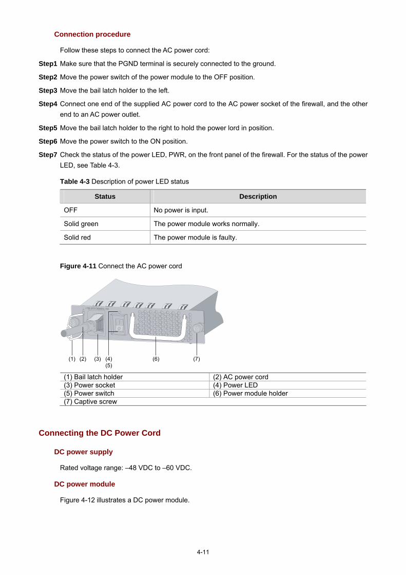
4-11
Connection procedure
Follow these steps to connect the AC power cord:
Step1 Make sure that the PGND terminal is securely connected to the ground.
Step2 Move the power switch of the power module to the OFF position.
Step3 Move the bail latch holder to the left.
Step4 Connect one end of the supplied AC power cord to the AC power socket of the firewall, and the other end to an AC power outlet.
Step5 Move the bail latch holder to the right to hold the power lord in position.
Step6 Move the power switch to the ON position.
Step7 Check the status of the power LED, PWR, on the front panel of the firewall. For the status of the power LED, see Table 4-3.
Table 4-3 Description of power LED status
Status Description
OFF No power is input.
Solid green The power module works normally.
Solid red The power module is faulty.
Figure 4-11 Connect the AC power cord
(1) (2) (3) (4)(5)
(6) (7)
(1) Bail latch holder (2) AC power cord (3) Power socket (4) Power LED (5) Power switch (6) Power module holder (7) Captive screw
Connecting the DC Power Cord
DC power supply
Rated voltage range: –48 VDC to –60 VDC.
DC power module
Figure 4-12 illustrates a DC power module.

4-12
Figure 4-12 DC power module
(1) Captive screw (2) DC input terminals (3) Power switch (4) Power LED (5) Power module handle
DC power cables
Figure 4-13 DC power cables
(1) (2) (3) (4) (5) (6)
(9) (8) (7) (1) Naked crimping terminal, OT, 6mm^2, M4, tin plating, naked ring terminal, 12 to 10 AWG (2) Heat shrink tube (3) Label 1 (+) (4) Power cable, 600V, UL10455, 5.3 mm^2, 10AWG, black, 45 A (5) Main label (6) Heat shrink tube (7) Power cable, 600 V, UL10455, 5.3 mm^2, 10AWG, blue, 45 A (8) Label 2 (–) (9) Common terminal, conductor cross section, 6mm^2, 20mm, 30 A, insertion depth 12 mm, black
Formula for calculating the cross section area of a DC power cable: S=2*I*L/(57*∆U)
Where,
I: Current in amperes.
L: Length of the power cable in meters.
∆V: Voltage drop on the power cable from the power distribution frame (PDF) to the firewall, usually, 3.2 V.
S: Cross section area of the power cable in square millimeters.
Connection procedure
Follow these steps to connect the DC power cables:

4-13
Step1 Move the power switch to the OFF position.
Step2 Remove the DC input terminals with a Philips screwdriver.
Step3 Attach the end marked with “–“ of the supplied blue DC power cable to the negative terminal (–) on the power module and fasten the screw.
Step4 Attach the end marked with “+“ of the supplied blue DC power cable to the passive terminal (+) on the power module and fasten the screw.
Step5 Connect the other end of the DC power cables to the wiring terminals of the DC power supply.
Step6 Move the power switch to the ON position.
Step7 Check the status of the power LED, PWR, on the front panel of the firewall. For the status of the power LED, see Table 4-3.
When connecting DC power cables, pay attention to the labels on the power cable to avoid incorrect connection.
Connecting Interface Cables
Connecting Console Cable
Follow these steps to connect the Console cable:
Step1 Select a configuration terminal.
A configuration terminal can be a standard ASCII terminal with an RS232 serial interface, or a common PC.
Step2 Connect the Console cable.
Disconnect the power supply to the firewall. Connect the RJ-45 connector of the console cable to the Console port on the firewall, and the DB-9 female connector to the serial interface on the configuration terminal.
Step3 Power on the firewall after verifying the connection.
After performing verification, power on the devices. The configuration terminal displays the startup banner of the firewall. For details, refer to “Firewall Power-on” in Chapter 5 “Starting and Configuring the Firewall.”
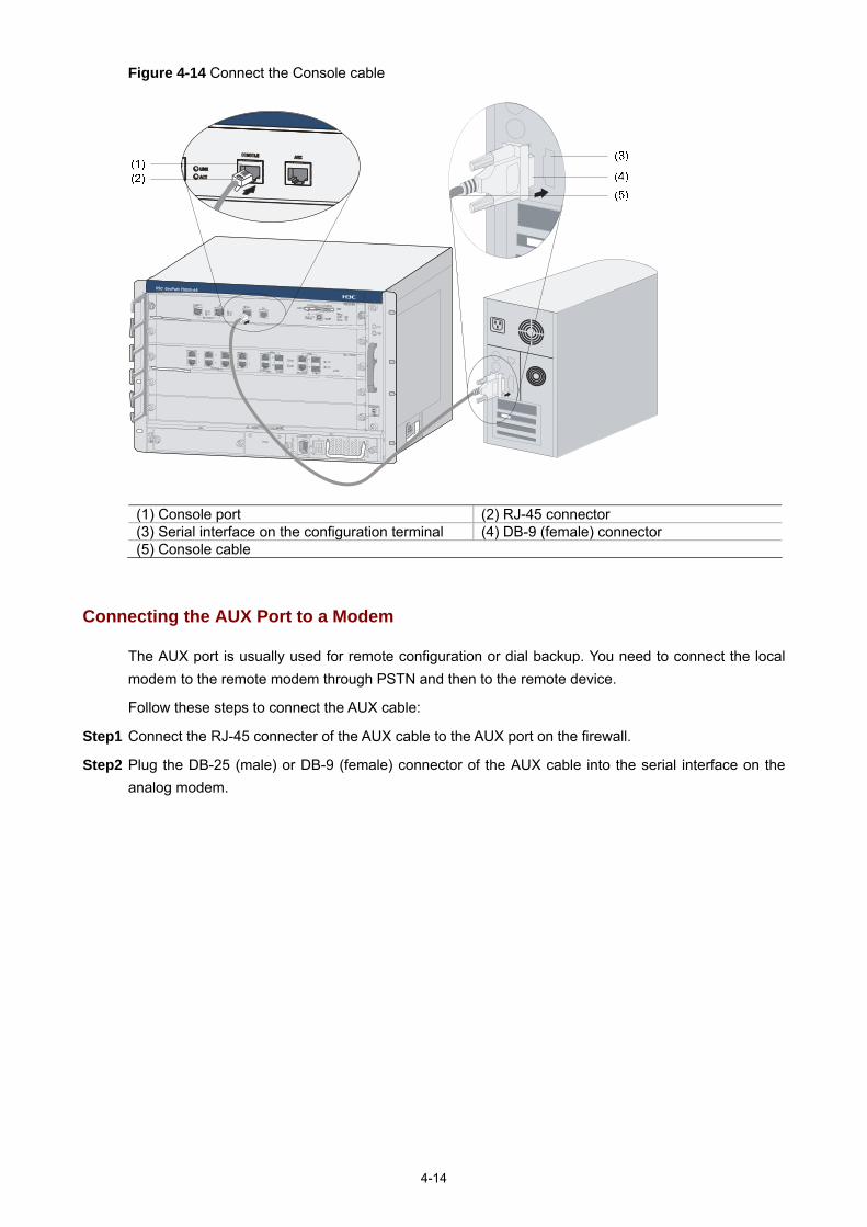
4-14
Figure 4-14 Connect the Console cable
(1) Console port (2) RJ-45 connector (3) Serial interface on the configuration terminal (4) DB-9 (female) connector (5) Console cable
Connecting the AUX Port to a Modem
The AUX port is usually used for remote configuration or dial backup. You need to connect the local modem to the remote modem through PSTN and then to the remote device.
Follow these steps to connect the AUX cable:
Step1 Connect the RJ-45 connecter of the AUX cable to the AUX port on the firewall.
Step2 Plug the DB-25 (male) or DB-9 (female) connector of the AUX cable into the serial interface on the analog modem.

4-15
Figure 4-15 Connect the AUX cable
(1)(2)(3)
(4)
(5)
(1) AUX port (AUX) (2) RJ-45 connector (3) AUX cable (4) Modem (5) DB-25 (male) or DB-9 (female) connector
Connecting the Management Ethernet Port and HA Port Cables
The management Ethernet port and HA port are 10Base-T/100Base-TX/1000Base-T RJ-45 auto-sensing interfaces. They are used to upgrade software and manage the device through a network management server, without using any service interface of the device. The management Ethernet port and HA port are only for managing the device and have no service processing capabilities such as data forwarding.
With support for automatic MDI/MDIX, the management Ethernet port and HA port use either a straight-through cable or a crossover cable for connection to a configuration terminal.
Follow these steps to connect the management Ethernet port or the HA port to the configuration terminal (take the management Ethernet port for example):
Step1 Turn off the power switches on all power modules of the firewall. Connect the RJ-45 connector of the console cable to the Console port on the firewall, and the DB-9 female connector to the serial interface on the configuration terminal.
Step2 Connect one end of the Ethernet cable to the management Ethernet port on the firewall and the other end to the Ethernet interface on the configuration terminal.
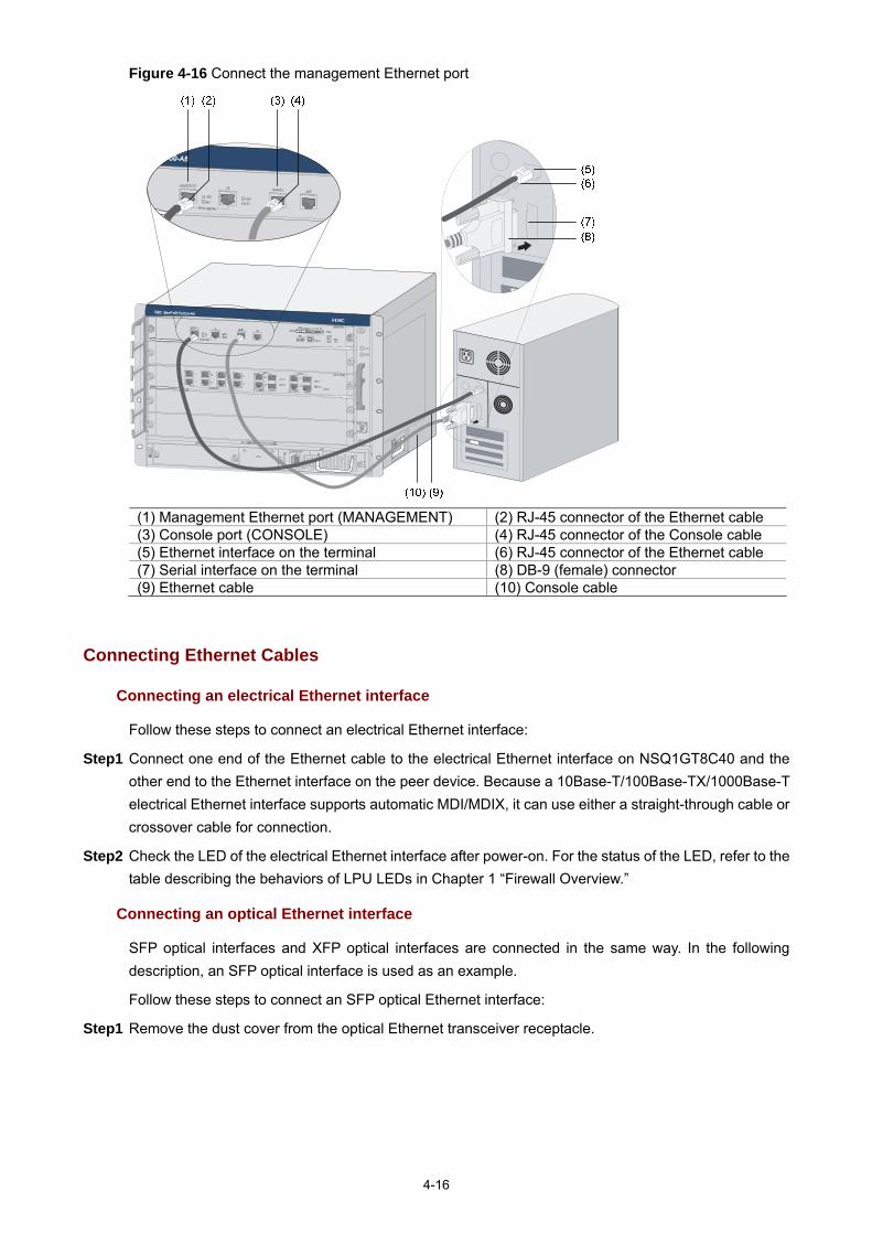
4-16
Figure 4-16 Connect the management Ethernet port
(1) Management Ethernet port (MANAGEMENT) (2) RJ-45 connector of the Ethernet cable (3) Console port (CONSOLE) (4) RJ-45 connector of the Console cable (5) Ethernet interface on the terminal (6) RJ-45 connector of the Ethernet cable (7) Serial interface on the terminal (8) DB-9 (female) connector (9) Ethernet cable (10) Console cable
Connecting Ethernet Cables
Connecting an electrical Ethernet interface
Follow these steps to connect an electrical Ethernet interface:
Step1 Connect one end of the Ethernet cable to the electrical Ethernet interface on NSQ1GT8C40 and the other end to the Ethernet interface on the peer device. Because a 10Base-T/100Base-TX/1000Base-T electrical Ethernet interface supports automatic MDI/MDIX, it can use either a straight-through cable or crossover cable for connection.
Step2 Check the LED of the electrical Ethernet interface after power-on. For the status of the LED, refer to the table describing the behaviors of LPU LEDs in Chapter 1 “Firewall Overview.”
Connecting an optical Ethernet interface
SFP optical interfaces and XFP optical interfaces are connected in the same way. In the following description, an SFP optical interface is used as an example.
Follow these steps to connect an SFP optical Ethernet interface:
Step1 Remove the dust cover from the optical Ethernet transceiver receptacle.

4-17
Figure 4-17 Remove the dust cover
Step2 Align an SFP transceiver with the optical SFP transceiver receptacle, with the side having a release lever facing outward. Then insert it into the receptacle.
Figure 4-18 Insert an optical transceiver
Step3 Identify the Rx and Tx ports on the SFP transceiver module. Plug the two LC connectors at one end of the fiber cable into the Rx and Tx ports of the local SFP transceiver and the two LC connectors at the other end to the Rx and Tx ports of the peer SFP transceiver. Note that the two LC connectors at each end of the fiber cable should be inserted into a Tx port and Rx port respectively.

4-18
Figure 4-19 Connect fiber cables
Step4 After power-on, check the SFP LED. For the status of the SFP LED, refer to the table describing the behaviors of the LEDs on NSQ1GT8C40 in Chapter 1 “Firewall Overview.”
Upon the connection of an XFP transceiver, you need to check the XFP LED. For details, refer to the table describing the behaviors of the LEDs on NSQ1XP20 in Chapter 1 “Firewall Overview.”
Note that:
Avoid excessively bending the optical fiber cables, with the curvature radium less than 10 cm (3.9 in.).
Ensure that the Tx and Rx of the SFP/XFP transceiver module are connected correctly. Keep the end-faces of optical fiber cables clean.
Do not look directly into an open optical Ethernet interface, because invisible rays emitted from the optical Ethernet interface may hurt your eyes.
Cover the dust cover if no optical transceiver is connected to the optical Ethernet interface.
Verifying Installation
Each time you power on the firewall during installation, you verify that:
There is enough space around the firewall for heat-dissipation and the workbench is stable enough.
The power supply matches the requirements of the firewall. The PGND cable of the firewall is correctly connected.

4-19
The firewall is correctly connected to other devices, such as the configuration terminal.
It is very important to verify the installation because instability and poor grounding of the firewall and an unmatched power supply will affect the operation of the firewall.

i
Table of Contents
5 Starting and Configuring the Firewall ·····································································································5-1 Setting up a Configuration Environment ·································································································5-1
Connecting the Firewall to a Configuration Terminal ······································································5-1 Setting the Parameters for the Configuration Terminal···································································5-1
Firewall Power-on ···································································································································5-4 Checklist for Firewall Power-on·······································································································5-4 Powering on the Firewall ·················································································································5-5 Checklist/Operations after Power-on·······························································································5-5
Startup Process·······································································································································5-5 Configuration Fundamentals···················································································································5-6 Command Line Interface·························································································································5-7
Features of the Command Line Interface························································································5-7 Command Line Interface ·················································································································5-7

5-1
5 Starting and Configuring the Firewall
You can only use the console port to make initial configuration of the firewall.
Setting up a Configuration Environment
Connecting the Firewall to a Configuration Terminal
For the connection of the firewall to the configuration terminal, refer to “Connecting the Console Cable” in Chapter 4 “Installing the Firewall”.
Setting the Parameters for the Configuration Terminal
Step1 Create a HyperTerminal connection. Select Start > Programs > Accessories > Communications > HyperTerminal, and enter a connection name in the Connection Description dialog box, as shown in Figure 5-1.
Figure 5-1 Create a connection
Step2 Select a connection port. Select a serial port from the Connect using drop-down list in the Connect To dialog box as shown below. Be sure to select the serial port to which the console cable is actually connected.

5-2
Figure 5-2 Select a port for local configuration connection
Step3 Set serial port parameters
Figure 5-3 Set serial port parameters
Set the properties of the serial port in the COM1 Properties dialog box, as shown in Table 5-1.

5-3
Table 5-1 Set serial port parameters
Item Value
Bits per second 9600 bps (default)
Data bits 8
Parity None
Stop bits 1
Flow control None
In case SecureCRT is used to configure the F5000-A5 firewall, flow control of the serial port must be set to Xon/Xoff; otherwise, the terminal screen displays nothing or only illegible characters.
To use the default settings, click Restore Defaults.
Step4 Click OK after setting the serial port parameters to enter the HyperTerminal window, as shown in Figure 5-4.
Figure 5-4 HyperTerminal window
Step5 Set HyperTerminal properties. In the HyperTerminal window, select File > Properties from the menu, and select the Settings tab to enter the properties setting dialog box, as shown in Figure 5-5. Select VT100 or Auto detect, and click OK to return to the HyperTerminal window.

5-4
Figure 5-5 Set HyperTerminal properties
Firewall Power-on
Checklist for Firewall Power-on
Before powering on the firewall, check that:
The power cord and ground cable are correctly connected. The voltage of the power source conforms to voltage requirements of the firewall. The console cable is correctly connected. The configuration terminal or PC is powered on and the
emulation program is properly configured. If an external CF card is needed to store applications, the CF card is properly installed.
Before powering on the firewall, locate the power switch so that you can disconnect the power supply in time in case of an emergency.

5-5
Powering on the Firewall
Turn on the power source. Turn on the power switch on the power module of the firewall.
Checklist/Operations after Power-on
After powering on the firewall, check that:
1) The LEDs on the MPU are normal. For the status of the LEDs, refer to “Table 1-2 Description of the device state LEDs” in Chapter 1 “Firewall Overview”.
2) The ventilation system works normally. You can hear that the fans are working. 3) The configuration terminal displays information normally. You can see the startup window on the
local configuration terminal. For more information, refer to “Startup Process” on page 5-5. 4) After completing the power-on self-test (POST), the system prompts you to press Enter. When the
command line prompt appears, you can proceed to configure the firewall.
Startup Process
After power-on, the firewall initializes its memory, and then runs the extended BootWare. The following information appears on the terminal screen:
System start booting...
Booting Normal Extend BootWare....
*************************************************************************
* *
* H3C SecPath F5000-A BootWare, Version 1.00 *
* *
*************************************************************************
Copyright (c) 2004-2008 Hangzhou H3C Technologies Co., Ltd.
Compiled Date : May 06 2008
CPU Type : XLR732
CPU L1 Cache : 32KB
CPU Clock Speed : 1000MHz
Memory Type : DDR2 SDRAM
Memory Size : 2048MB
Memory Speed : 533MHz
BootWare Size : 1536KB
Flash Size : 4MB
cfa0 Size : 247MB
CPLD Version : 131.0
PCB Version : Ver.A
BootWare Validating
Press Ctrl+B to enter extended boot menu...
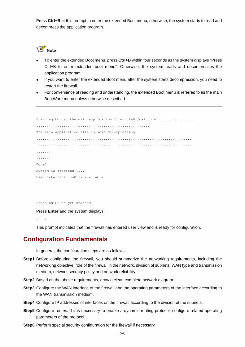
5-6
Press Ctrl+B at this prompt to enter the extended Boot menu; otherwise, the system starts to read and decompress the application program.
To enter the extended Boot menu, press Ctrl+B within four seconds as the system displays “Press Ctrl+B to enter extended boot menu”. Otherwise, the system reads and decompresses the application program.
If you want to enter the extended Boot menu after the system starts decompression, you need to restart the firewall.
For convenience of reading and understanding, the extended Boot menu is referred to as the main BootWare menu unless otherwise described.
Starting to get the main application file--cfa0:/main.bin!..................
......................................................
The main application file is self-decompressing
..........................................................................
..........................................................................
.......
.......
Done!
System is starting.....
User interface con0 is available.
Press ENTER to get started.
Press Enter and the system displays:
<H3C>
This prompt indicates that the firewall has entered user view and is ready for configuration.
Configuration Fundamentals
In general, the configuration steps are as follows:
Step1 Before configuring the firewall, you should summarize the networking requirements, including the networking objective, role of the firewall in the network, division of subnets, WAN type and transmission medium, network security policy and network reliability.
Step2 Based on the above requirements, draw a clear, complete network diagram.
Step3 Configure the WAN interface of the firewall and the operating parameters of the interface according to the WAN transmission medium.
Step4 Configure IP addresses of interfaces on the firewall according to the division of the subnets.
Step5 Configure routes. If it is necessary to enable a dynamic routing protocol, configure related operating parameters of the protocol.
Step6 Perform special security configuration for the firewall if necessary.

5-7
Step7 Perform reliability configuration for the firewall if necessary.
For the configuration details of the protocols or functions of the firewall, refer to H3C SecPath Series Security Products User Manual.
Command Line Interface
Features of the Command Line Interface
The command line interface (CLI) of the firewall enables you to configure, manage, and maintain the firewall.
The CLI provides the following functions:
Allows you to perform local configuration through the console port. Allows you to perform local or remote configuration and directly log into and manage other devices
by using the telnet command. Provides online help information that is available by entering “?”. Provides network diagnostic tools, such as Tracert and Ping, for quick diagnosis of network
connectivity. Provides all kinds of detailed debugging information to help diagnose network faults. Supports the auto-complete function. If you enter a conflict-free part of a command, the command
will be interpreted. For example, you just need to enter dis for display. Supports the suggest function. For example, if you type dis and press Tab, all commands starting
with dis will be displayed.
Command Line Interface
The command line interface of the firewall provides plenty of configuration commands. All the commands are grouped in system view. Each group corresponds to a view. You can switch between different configuration views by using corresponding commands. In general, only certain commands can be executed in a particular view. However, some commonly used commands, such as ping and display current-configuration, can be executed in any view.

i
Table of Contents
6 Maintaining Software·································································································································6-1 Overview ·················································································································································6-1
Files ·················································································································································6-1 BootWare Program File ···················································································································6-1 Application Files ······························································································································6-1 Configuration Files···························································································································6-2 Software Maintenance Methods······································································································6-3
BootWare Menu ······································································································································6-5 Main Menu·······································································································································6-5 Serial Submenu ·······························································································································6-7 Ethernet Submenu···························································································································6-8 File Control Submenu······················································································································6-9 BootWare Operation Submenu ·······································································································6-9 Storage Device Operation Submenu·····························································································6-10
Upgrading BootWare and Applications Through a Serial Port······························································6-10 Introduction to Xmodem ················································································································6-10 Modifying Serial Port Parameters··································································································6-11 Upgrading an Application ··············································································································6-13 Upgrading BootWare·····················································································································6-14
Upgrading BootWare and Applications Using TFTP·············································································6-16 Upgrading an Application Using TFTP on the BootWare Menu····················································6-17 Upgrading and Backing Up an Application Using TFTP at the CLI···············································6-20
Upgrading BootWare and Applications Using FTP···············································································6-22 Upgrading an Application Using FTP on the BootWare Menu······················································6-22 Upgrading and Backing Up an Application Using FTP at the CLI ·················································6-24
Maintaining Application and Configuration Files···················································································6-29 Displaying All Files ························································································································6-29 Setting Application Files Attributes································································································6-30 Deleting a File································································································································6-32
Dealing with Password Loss ·················································································································6-33 BootWare Password Loss ·············································································································6-33 Dealing With User Password Loss ································································································6-34 Dealing With Super Password Loss ······························································································6-35
Backing Up and Restoring BootWare ···································································································6-35 Backing Up the Entire BootWare···································································································6-36 Restoring the Entire BootWare······································································································6-36

6-1
6 Maintaining Software
Overview
Files
Three types of files need to be managed on the firewall:
BootWare program file Application file Configuration file
BootWare Program File
The BootWare program file is used for booting the application program when the firewall starts and is stored in the flash memory. The entire BootWare program consists of a basic section and an extended section.
The basic section is used for the basic initialization of the system. The extended section provides abundant human-computer interaction (HCI) functions and is used
to initialize interfaces and upgrade the application program and the boot system. The entire BootWare program is the combination of the basic section and the extended section.
After the basic section is loaded, you can load and upgrade the extended section on the menu of the basic section.
Application Files
The firewall supports the dual image function. By default, the system defines three types of application files for boot.
Main application file (with the attribute of M) Backup application file (with the attribute of B) Secure application file (with the attribute of S)
These three types of application files are stored in a CF card.
By default, they are written into the built-in CF card before delivery.
If you have uploaded all the three types of application files into the built-in CF card, the system will boot using these three files in the M-B-S order. For information about attribute and boot order modifications for application files, refer to "Maintaining Application and Configuration Files” on page 6-29.
The following gives the default names of the application files and their priorities for system boot.
Main application file. The default name is main.bin. It is the default application file used for system boot.
Backup application file. The default name is backup.bin. When booting with the main application file fails, the system uses the backup application file for startup.
Secure application file. The default name is secure.bin. When booting with the main and backup application files fails, the system uses the secure application file for startup. If booting with the secure application file fails, the system displays a boot failure.

6-2
Note that:
An application file with the attribute of M, B, or S can be used for system startup, but one with an attribute of N/A (that is, an application file without a specific attribute assigned to it) cannot.
You can modify the names of application files at the CLI after the application program is started. You can modify the attributes of application files on the BootWare menu or the CLI after the
application program is started. Because the secure application file is the last resort for system boot, you cannot change its attribute or turn another type of application file into a secure application file by means of attribute modification. You can only download it on the BootWare menu.
An application file can have different attributes assigned, but only one file of the same type (M, B, or S) can exist in the CF card at a time. For instance, if a file in the CF card has both M and B attributes, no other file with the attribute of M or B can exist in the CF card. If the attribute of another file is changed from N/A to B, the existing file that has both M and B attributes will lose its B attribute.
Configuration Files
The configuration files are used to store the configuration information of the firewall and load the configuration information at system boot.
1) A system that supports the main and backup attributes of configuration files defines three types of configuration files by default:
Main configuration file (with the attribute of M) Backup configuration file (with the attribute of B) Secure configuration file (with the attribute of S)
The main and backup configuration files are mainly used as follows:
When the main configuration file is damaged or lost, the backup configuration file is used to load the configuration information. This double protection mechanism enhances the security and reliability of the file system.
When saving the current configuration file, you can specify its attribute as main or backup. If no attribute is specified, N/A is used for the configuration file.
You can select to delete the main or backup configuration file. For a configuration file with both M and B attributes, you can select to remove its M or B attribute.
You can define a configuration file as the one to be used at the next boot by changing its attribute to M.
The secure configuration file is used when the system fails to boot using the main, and then the backup configuration file.
2) A system that does not support the main and backup attributes of configuration files define only one type of configuration file, denoted by N/A.
The configuration files have a file name extension of .cfg.
By default, they are written into the built-in CF card before delivery.
You can configure the system to support the main and backup attributes of configuration files as needed. However, after doing that, you cannot restore the single type configuration file mode.
The system will select a configuration file as follows:
1) If the system supports the main and backup attributes of configuration files, the system: Uses the main configuration file to initialize the configuration if the main file exists. Uses the backup configuration file to initialize the configuration if the main file does not exist. Uses default settings for initialization if the backup file does not exist either.
2) If the system does not support the main and backup attributes of configuration files, the system:

6-3
Uses the default configuration file (if any) to initialize the configuration. The default configuration file is startup.cfg. Note that you can use the startup saved-configuration cfgfile command to define the configuration file to be used at the next system boot.
Uses the default settings if the default configuration file does not exist.
Note that:
The F5000-A5 does not support the main and backup attributes of configuration files. You can rename the configuration files at the CLI after the application program is started.
A configuration file name cannot be longer than 64 characters, including a drive letter and a string terminator. For instance, if the drive letter is “cfa0:/”, the file name without the drive letter and string terminator can be at most [ 64 – 1 – 6 ] = 57 characters in length.
If the file name with the drive identifier and string terminator excluded contains more than 57 characters, errors will occur in file operation. Typically, a file name with the driver identifier and string terminator excluded is recommended to contain no more than 16 characters.
At BootWare boot, the names of the configuration files will be displayed, but the types will still be displayed as N/A.
For details about the startup saved-configuration cfgfile command, refer to H3C SecPath Series Security Products User Manual.
Software Maintenance Methods
You can maintain the firewall software in the following two ways:
Upgrade BootWare and application programs using the Xmodem protocol through a serial port. Upgrade BootWare and application programs using the FTP or TFTP protocol through an Ethernet
interface. This upgrade can be carried out on the BootWare menu or at the CLI.
Note that:
When upgrading an application file, if you select to overwrite the existing application file, make sure the power supply works normally during the upgrade process. Otherwise, the application upgrade will fail and the existing application file will be damaged. If the existing application file is the only one for booting the system, the device will fail at the next reboot.
When upgrading the basic BootWare section, make sure the power supply works normally during the upgrade process. Otherwise, the basic BootWare section will be damaged, resulting in failure of device reboot.
If upgrading the extended BootWare section fails, you can upgrade it again.

6-4
The BootWare program is upgraded together with the Comware application program. You do not need to upgrade the BootWare program separately. After you upgrade the Comware application program to the latest version and restart the device, the system checks whether the current BootWare version is consistent with the one in the host application. If not, the system automatically upgrades the BootWare program.
When a service card is started up, it automatically checks the current BootWare version. If the BootWare version bound to the Comware application program is different from the current BootWare version, the system upgrades the current BootWare version automatically.
To use correct files for upgrading, check the current versions of the BootWare and Comware application programs. For associations between Comware versions and BootWare versions, refer to the hardware and software compatibility matrix in Release Notes.
Figure 6-1 BootWare and Comware upgrade flow
Using
Xmodem
Using
TFTP
UsingFTP

6-5
BootWare Menu
Main Menu
When the firewall is powered on, it first runs the basic segment and then the extended segment of BootWare. The following information is displayed on the configuration terminal:
System start booting...
Booting Normal Extend BootWare....
*************************************************************************
* *
* H3C SecPath F5000-A BootWare, Version 1.00 *
* *
*************************************************************************
Copyright (c) 2004-2008 Hangzhou H3C Technologies Co., Ltd.
Compiled Date : May 06 2008
CPU Type : XLR732
CPU L1 Cache : 32KB
CPU Clock Speed : 1000MHz
Memory Type : DDR2 SDRAM
Memory Size : 2048MB
Memory Speed : 533MHz
BootWare Size : 1536KB
Flash Size : 4MB
cfa0 Size : 247MB
CPLD Version : 131.0
PCB Version : Ver.A
BootWare Validating
Press Ctrl+B to enter extended boot menu...
Starting to get the main application file--cfa0:/main.bin!...............
..........................................................................
..................................................................
The main application file is self-decompressing
Press Ctrl + B to enter the extended BootWare menu or let the system start to read and decompress the main application file.

6-6
To enter the extended BootWare menu, press Ctrl+B within four seconds after the system displays “Press Ctrl+B to enter extended boot menu”. Otherwise, the system reads and decompresses the main application file.
If you want to enter the extended BootWare menu after the system starts main application file decompression, you need to restart the firewall.
For convenience, the extended BootWare menu is referred to as the main BootWare menu unless otherwise specified.
Press Ctrl + B when “Press Ctrl+B to enter extended boot menu...” appears, and then the system displays:
Please input BootWare password:
After you type the correct BootWare password, the system will display the BootWare menu, which provides:
The name of the operating device. A Storage Device Operation option for you to select the storage device from which you are going to
loading the application file.
Note that:
The initial BootWare password is null. You have three chances to enter the correct BootWare password. If you fail to enter the correct
password for three times, the system will be halted and you need to restart the firewall to enter the correct password.
You can enter the main menu only after you enter the correct BootWare password. Note: The current operating device is cfa0
Enter < Storage Device Operation > to select device.
========================<EXTEND-BOOTWARE MENU>========================
|<1> Boot System |
|<2> Enter Serial SubMenu |
|<3> Enter Ethernet SubMenu |
|<4> File Control |
|<5> Modify BootWare Password |
|<6> Skip Current System Configuration |
|<7> BootWare Operation Menu |
|<8> Clear Super Password |
|<9> Storage Device Operation |
|<0> Reboot |
======================================================================
Enter your choice(0-9):
Table 6-1 gives a detailed description of the menu.

6-7
Table 6-1 BootWare main menu
Menu item Description
<1> Boot System Load and boot system applications from a CF card.
<2> Enter Serial SubMenu Enter the serial port submenu. For detailed description of this submenu, refer to “Serial Submenu“ on page 6-7.
<3> Enter Ethernet SubMenu Enter the Ethernet submenu. For detailed description of this submenu, refer to “Ethernet Submenu” on page 6-8.
<4> File Control Enter file control submenu. For detailed description of this submenu, refer to “File Control Submenu” on page 6-9.
<5> Modify BootWare Password Modify the BootWare password.
<6> Skip Current System Configuration
Skip current system configuration. This operation takes effect only once. This operation is generally used when you lose the password.
<7> BootWare Operation Menu
Enter BootWare operation submenu For detailed description of this submenu, refer to “BootWare Operation Submenu“ on page 6-9.
<8> Clear Super Password
Clear the super password. The super password is used in user level switching. No super password is set by default. This setting is valid for the first reboot of the firewall only. The super password will be restored after a second reboot.
<9> Storage Device Operation Enter the storage device operation menu. This operation allows you to select a storage medium in which the application will be used to boot the system.
<0> Reboot Reboot the firewall.
In the firewall, the built-in CF card is identified with cfa0, while the external CF card is identified with cfb0.
If an application file is stored in the external CF card, you need to select 9 on the main BootWare menu and then choose to load the application from cfb0.
Serial Submenu
Select 2 on the main menu to enter the serial submenu, where you can upgrade application files and the BootWare program through Xmodem.
The system displays:
=========================<Enter Serial SubMenu>=======================

6-8
|Note:the operating device is cfa0 |
| <1> Download Application Program To SDRAM And Run |
| <2> Update Main Application File |
| <3> Update Backup Application File |
| <4> Update Secure Application File |
| <5> Modify Serial Interface Parameter |
| <0> Exit To Main Menu |
======================================================================
Enter your choice(0-5):
Items on this submenu are described in Table 6-2.
Table 6-2 BootWare serial submenu
Menu item Description
<1> Download Application Program To SDRAM And Run
Download an application to SDRAM through the serial port and run the program.
<2> Update Main Application File Upgrade the main application file
<3> Update Backup Application File Upgrade the backup application file
<4> Update Secure Application File Upgrade the secure application file
<5> Modify Serial Interface Parameter Modify serial port parameters
<0> Exit To Main Menu Return to the main menu
Ethernet Submenu
Select 3 on the main menu to enter the Ethernet submenu, where you can upgrade application files and the BootWare program through FTP or TFTP.
The system displays:
=========================<Enter Ethernet SubMenu>=====================
|Note:the operating device is cfa0 |
| <1> Download Application Program To SDRAM And Run |
| <2> Update Main Application File |
| <3> Update Backup Application File |
| <4> Update Secure Application File |
| <5> Modify Ethernet Parameter |
| <0> Exit To Main Menu |
| < Ensure The Parameter Be Modified Before Downloading! > |
======================================================================
Enter your choice(0-5):
Items on this submenu are described in Table 6-3.
Table 6-3 Ethernet submenu
Menu item Description
<1> Download Application Program To SDRAM And Run
Download an application to SDRAM and run the program.
<2> Update Main Application File Upgrade the main application file

6-9
Menu item Description
<3> Update Backup Application File Upgrade the backup application file
<4> Update Secure Application File Upgrade the secure application file
<5> Modify Ethernet Parameter Modify Ethernet interface parameters
<0> Exit To Main Menu Return to the main menu
File Control Submenu
Select 4 on the main menu to enter the file control submenu, where you can view, modify, or delete application files.
The system displays:
==============================<File CONTROL>==========================
|Note:the operating device is cfa0 |
| <1> Display All File(s) |
| <2> Set Application File type |
| <3> Delete File |
| <0> Exit To Main Menu |
======================================================================
Enter your choice(0-3):
Items on this submenu are described in Table 6-4.
Table 6-4 File control submenu
Menu item Description
<1> Display All File(s) Display all files.
<2> Set Application File type Set the application file type.
<3> Delete File Delete a file.
<0> Exit To Main Menu Return to the main menu.
BootWare Operation Submenu
Select 7 on the main menu to enter the BootWare operation submenu:
========================<BOOTWARE Operation Menu>=====================
|Note:the operating device is cfa0 |
| <1> Backup Full BootWare |
| <2> Restore Full BootWare |
| <3> Update BootWare By Serial |
| <4> Update BootWare By Ethernet |
| <0> Exit To Main Menu |
======================================================================
Enter your choice(0-4):
Items on this submenu are described in Table 6-5.

6-10
Table 6-5 BootWare operation submenu
Menu item Description
<1> Backup Full BootWare Back up the entire BootWare.
<2> Restore Full BootWare Restore the entire BootWare.
<3> Update BootWare By Serial Upgrade BootWare through a serial port.
<4> Update BootWare By Ethernet Upgrade BootWare through an Ethernet interface.
<0> Exit To Main Menu Return to the main menu.
Storage Device Operation Submenu
Select 9 on the main menu to enter the storage device operation submenu:
==========================<DEVICE CONTROL>============================
|<1> Display All Available Nonvolatile Storage Device(s) |
|<2> Set The Operating Device |
|<3> Set The Default Boot Device |
|<0> Exit To Main Menu |
======================================================================
Enter your choice(0-3):
Items on this submenu are described in Table 6-6.
Table 6-6 Storage device operation submenu
Menu item Description
<1> Display All Available Nonvolatile Storage Device(s) Display all available storage devices.
<2> Set The Operating Device Configure the operating device.
<3> Set The Default Boot Device Configure the default boot device.
<0> Exit To Main Menu Return to the main menu.
Upgrading BootWare and Applications Through a Serial Port
Introduction to Xmodem
Xmodem is used for upgrading BootWare and applications through a serial port.
Xmodem is a file transfer protocol that is widely used due to its simplicity and high performance. Xmodem transfers files through a serial port. It supports two types of data packets (128 bytes and 1 KB), two check methods (checksum and CRC), and error packet retransmission mechanism (generally the maximum number of retransmission attempts is 10).
An Xmodem transmission procedure is completed by the cooperation of a receiving program and a sending program. The receiving program sends a negotiation character to negotiate a packet check method. After the negotiation, the sending program starts to transmit data packets. Upon receiving a complete data packet, the receiving program checks the packet using the agreed method.
If the check succeeds, the receiving program sends an acknowledgement character and the sending program proceeds to send another packet.
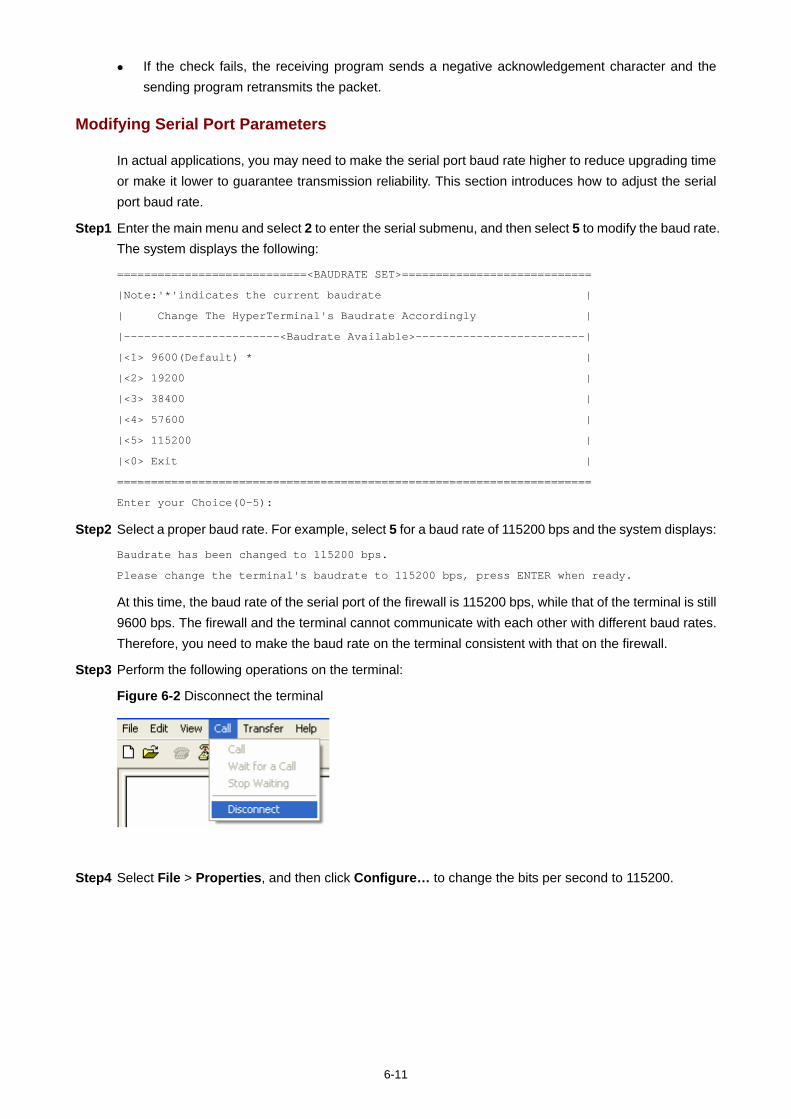
6-11
If the check fails, the receiving program sends a negative acknowledgement character and the sending program retransmits the packet.
Modifying Serial Port Parameters
In actual applications, you may need to make the serial port baud rate higher to reduce upgrading time or make it lower to guarantee transmission reliability. This section introduces how to adjust the serial port baud rate.
Step1 Enter the main menu and select 2 to enter the serial submenu, and then select 5 to modify the baud rate. The system displays the following:
============================<BAUDRATE SET>============================
|Note:'*'indicates the current baudrate |
| Change The HyperTerminal's Baudrate Accordingly |
|-----------------------<Baudrate Available>-------------------------|
|<1> 9600(Default) * |
|<2> 19200 |
|<3> 38400 |
|<4> 57600 |
|<5> 115200 |
|<0> Exit |
======================================================================
Enter your Choice(0-5):
Step2 Select a proper baud rate. For example, select 5 for a baud rate of 115200 bps and the system displays:
Baudrate has been changed to 115200 bps.
Please change the terminal's baudrate to 115200 bps, press ENTER when ready.
At this time, the baud rate of the serial port of the firewall is 115200 bps, while that of the terminal is still 9600 bps. The firewall and the terminal cannot communicate with each other with different baud rates. Therefore, you need to make the baud rate on the terminal consistent with that on the firewall.
Step3 Perform the following operations on the terminal:
Figure 6-2 Disconnect the terminal
Step4 Select File > Properties, and then click Configure… to change the bits per second to 115200.

6-12
Figure 6-3 Modify the baud rate on the terminal
Step5 Select Call > Call to establish a new connection.
Figure 6-4 Establish a new connection
Step6 Press Enter on the console terminal. The system displays the current baud rate and returns to the previous menu.
The system displays:
The current baudrate is 115200 bps
After downloading files with a changed baud rate, you need to restore the baud rate on the HyperTerminal to 9600 bps to ensure normal display on the console screen when the system boots or reboots.

6-13
Upgrading an Application
The application upgrading on a serial port is implemented on the serial submenu.
Step1 Select 2 on the main menu to enter the serial submenu. For details about this submenu, refer to “Serial Submenu” on page 6-7.
The following example shows how to upgrade the main application file main.bin:
To accelerate the upgrading speed, you can modify the serial port baud rate before upgrading the main application file. For details, refer to “Modifying Serial Port Parameters” on page 6-11.
Step2 Select 2 on the serial submenu. The system displays:
Please Start To Transfer File, Press <Ctrl+C> To Exit.
Waiting...CCCCCCCCCCCCCCCCCCCC
Step3 Select Transfer > Send file… in the terminal window. The following dialog appears:
Figure 6-5 Send file dialog box
Step4 Click Browse… to select the application file to be downloaded, select Xmodem from the Protocol drop-down list, and click Send. The following dialog box appears:
Figure 6-6 Sending file dialog box
After the application file is downloaded, the following information appears on terminal interface, indicating a successful upgrade.

6-14
Download successfully!
14092032 bytes downloaded!
The system then prompts you to enter the target file name.
Input the File Name:
Step5 Input the file name.
1) If the file name is different from that of any existing file in the storage medium, the application file is saved using the specified file name, for example,
Input the File Name:main.bin
Updating File cfa0:/main.bin......... ..........................
........................................................................................
........................................................................................
.........................................Done!
After that, you need to return to the main menu, enter the file control submenu, and set this application file as the default boot program. The system will use this program at next system reboot. For description of the default boot program, refer to “Setting Application Files Attributes” on page 6-30.
2) If the file name already exists in the storage medium, the system displays: The file is exist,will you recover it? [Y/N]
Enter Y to overwrite the existing application file and complete the upgrading operation. The system uses the new application file at next system reboot.
Enter N and the system displays: Cancel to overwrite the file.
Failed!
As a result, the existing application file is not overwritten and the upgrading operation fails.
The size of an application is often over 10 MB. Even if the baud rate is 115200 bps, it takes about 30 minutes to upgrade the application through a serial port. Therefore, you are recommended to upgrade an application through Ethernet.
Upgrading BootWare
To upgrade the BootWare, follow these steps:
Step1 Enter the main BootWare menu (refer to “Main Menu” on page 6-5).
Step2 Select 7 to enter the BootWare operation submenu, where you can perform all BootWare operations. For detailed description, refer to “BootWare Operation Submenu” on page 6-9.
The following example shows how to upgrade the entire BootWare.
You need to upgrade the basic segment and then the extended segment to upgrade the BootWare.
Step3 Select 3 on the BootWare operation submenu. The system displays:
=================<BOOTWARE OPERATION SERIAL SUB-MENU>================
|<1> Update Full BootWare |
|<2> Update Extend BootWare |

6-15
|<3> Update Basic BootWare |
|<4> Modify Serial Interface Parameter |
|<0> Exit To Main Menu |
=====================================================================
Enter your choice(0-4):
To accelerate the upgrade speed, you need to modify the serial port baud rate.
Step4 Select 4 to modify the serial baud rate to 115200 bps. To ensure communication between the device and the terminal, you need to make the baud rate of the terminal consistent with that of the serial port. For the modification of the terminal baud rate, refer to “Modifying Serial Port Parameters” on page 6-11.
Step5 After setting the baud rate, return to the BootWare operation submenu and select 1. The system displays the following:
Waiting ...CCCCCCCCCCCCCCCCCCCCCCCCC...
Step6 Select Transfer > Send file… in the terminal window. The following dialog appears.
Figure 6-7 Send file dialog box
Step7 Click Browse… to specify the application file to be downloaded, select Xmodem from the Protocol drop-down list, and click Send. The following dialog box appears:
Figure 6-8 Sending file dialog box

6-16
After the application file is downloaded, the following information appears on terminal interface, indicating a successful upgrade.
Download successfully!
14092032 bytes downloaded!
Updating Basic BootWare? [Y/N]
Step8 Upgrade the BootWare.
1) If you enter N, the system displays: Not update the Basic!
Updating Extend BootWare? [Y/N]
The system stops upgrading the basic segment and asks you whether to upgrade the extended segment or not.
2) If you enter Y, the system proceeds to upgrade the basic segment: Updating Basic BootWare...............Done!
Updating Extend BootWare? [Y/N]Y
The system finishes upgrading the basic segment and asks you whether to upgrade the extended segment or not.
If you type N, the system does not upgrade the extended segment. In this case, the system only has the basic segment upgraded.
If you type Y, the system proceeds to upgrade the extended segment: Updating Extend BootWare.................Done!
At this prompt, the extended segment is successfully upgraded.
By now, the entire BootWare has been successfully upgraded.
The BootWare program is upgraded together with the Comware application. You do not need to upgrade the BootWare separately. After the Comware is upgraded to the latest version, the system automatically upgrades the BootWare when the system reboots.
When a service card is started up, it automatically checks the current BootWare version. If the BootWare version bound to the Comware application is different from the current BootWare version, the system upgrades the current BootWare version automatically.
The file name, size, and path in the above figures are for reference only. Check the current BootWare and application versions before upgrading them.
Upgrading BootWare and Applications Using TFTP
If the application file is large, you can use TFTP to upgrade it to reduce upgrade time.
Trivial File Transfer Protocol (TFTP), a protocol in the TCP/IP suite, is used for file transfer between client and server. It provides not-so-complex and low-cost file transfer services. TFTP provides unreliable data transfer services over UDP and does not provide any access authorization and authentication mechanism. It employs timeout and retransmission mechanisms to guarantee successful data delivery.

6-17
The firewall can serve as the TFTP client. The filer server serves as the TFTP server. You can upload/download the application file on the firewall to/from the file server.
There are two approaches to upgrading BootWare and application files using TFTP:
On the BootWare menu At the CLI
Upgrading an Application Using TFTP on the BootWare Menu
1) Set up a TFTP upgrading environment.
Figure 6-9 Set up a TFTP upgrading environment
The firewall serves as the TFTP client and the PC serves as the TFTP server. Connect the management Ethernet port on the firewall to the PC using a crossover Ethernet cable.
Ensure the firewall and the PC are reachable to each other. Configure the IP address of the management Ethernet port as 192.168.80.10 and that of the PC as 192.168.80.200.
Start the TFTP server on the PC and set the path where the application file is stored.

6-18
The TFTP server is not provided with the device. You need to purchase and install it. You can upgrade applications and the BootWare through the console port or the management
Ethernet port.
2) Configure Ethernet port parameters on the BootWare menu.
Enter the main menu and select 3 to enter the Ethernet submenu. Select 5 to set the Ethernet port parameters.
======================<ETHERNET PARAMETER SET>========================
|Note: '.' = Clear field. |
| '-' = Go to previous field. |
| Ctrl+D = Quit. |
======================================================================
Protocol (FTP or TFTP):tftp
Load File Name :main.bin
:main.bin
Target File Name :main.bin
:main.bin
Server IP Address :192.168.80.200
Local IP Address :192.168.80.10
Gateway IP Address :
FTP User Name :
FTP User Password :
Table 6-7 Command output description for setting Ethernet port parameters
Item Description
'.' = Clear field Shortcut key is to clear the current input.
'-' = Go to previous field Shortcut key is to return to the previous field.
Ctrl+D = Quit Shortcut key Ctrl + D is to quit the parameter setting page.
Protocol (FTP or TFTP) Choose to upgrade applications using FTP or TFTP.
Load File Name
Name of the download file, which needs to be the same as that of the actual file to be downloaded. At the same time, you need to set the download path on the FTP/TFTP Client. Note that:
The first “main.bin“ is the previous file name automatically remembered in the system.
The second “main.bin“ is the file name set by the user. The file name with an extension, such as .bin, cannot contain
more that 50 characters.

6-19
Item Description
Target File Name
Name of the target file after the file is downloaded to the firewall. The extension of the target file needs to be the same as that of the download file. Note that:
The first “main.bin“ is the previous file name automatically remembered in the system.
The second “main.bin“ is the file name set by the user.
Server IP Address IP address of the FTP/TFTP server
Local IP Address IP address of the interface connecting to the FTP/TFTP server.
Gateway IP Address IP address of the gateway. You need not configure this IP address.
FTP User Name FTP username, which will be used in FTP download. TFTP download needs no username.
FTP User Password FTP password, which will be used in FTP download. TFTP download needs no password.
To use the default parameter after the colon, press Enter directly. If the Ethernet port parameter CRC appears faulty, the system modifies the parameters to the
default settings and displays “Check net params crc error, use the default value.”
3) After the configuration, the system automatically returns to the Ethernet submenu, where you can select 2 to upgrade the main application file.
Loading.........
................
...... .... done
14092032 bytes downloaded!
Updating File cfa0:/main.bin
.........Done!
4) After the upgrading is finished, select 0 to return to the main menu and select 1 to reboot the system from the CF card.
If the input application file name already exists on the CF card, the system displays “The file is exist, will you recover it? [Y/N]”. If you enter Y, the input application file overwrites the one in the CF card and becomes the only application file of that type.
Make sure the available space in the CF card is sufficient. Otherwise, the system displays “The free space isn’t enough!”
For detailed description of file types, refer to “Overview”.

6-20
Upgrading and Backing Up an Application Using TFTP at the CLI
1) Set up a TFTP upgrading environment The firewall serves as the TFTP client and the PC serves as the TFTP server. For the procedures of setting up a upgrading environment, refer to “Upgrading an Application Using
TFTP on the BootWare Menu”. Run the terminal emulation program on the PC, and configure the IP addresses of the client and
server to be on the same subnet. Ensure the firewall and the PC are reachable to each other. In this example, configure the IP address of the management Ethernet port as 192.168.80.10 and that of the PC as 192.168.80.200.
You can use the ping command to verify the connectivity.
You can upgrade applications of the device through the console port or the management Ethernet port.
2) View the files in the storage medium and its available space.
To prepare for upgrading application files, use the dir command on the terminal to view the files stored in the current file system and the available space of the storage device.
<H3C>dir
Directory of cfa0:/
0 drw- - Oct 28 2000 04:09:30 logfile
1 -rw- 24802996 Oct 21 2007 17:03:26 main.bin
2 -rw- 1355 Oct 04 2007 17:22:12 startup.cfg
3 -rw- 24802996 Sep 13 2037 13:21:20 backup.bin
505480 KB total (456576 KB free)
File system type of cfa0: FAT16
Table 6-8 Output description
Field Description
Directory of cfa0:/ Name of the existing directory
505480 KB total (456576 KB free) Used space of the CF card (available space)
File system type of cfa0: FAT16 File system type of the CF card
3) Upgrade an application
Using TFTP, you can download an application file from the server to the firewall and overwrite the existing main application file to implement application upgrading. The upgraded application file takes effect when the device reboots.
# Download the application file main.bin from the PC to the firewall.
<H3C> tftp 192.168.80.200 get main.bin main.bin

6-21
The file main.bin exists. Overwrite it? [Y/N]:y
Verifying server file...
Deleting the old file, please wait...
File will be transferred in binary mode
Downloading file from remote TFTP server, please wait...|
TFTP: 14092032 bytes received in 907 second(s)
File downloaded successfully.
When you download an application file, if a file with the same name exists on the firewall, the system asks you whether to overwrite the existing file on your device. You need to enter Y for confirmation.
For details about the ftfp command, refer to H3C SecPath Series Security Products User Manual. You can upgrade a configuration file in the way you upgrade an application file. A configuration file
can be modified using a text editor. You can modify a configuration file and then download the modified configuration file to the firewall to finish upgrading the configuration file. The modification takes effect after the firewall reboots.
4) Backup an application file
Using TFTP, you can backup an application file by uploading it from the firewall to the PC.
# Upload file main.bin on the firewall to the PC and save it as main.bin.
<H3C> tftp 192.168.80.200 put main.bin main.bin
File will be transferred in binary mode
Sending file to remote TFTP server. Please wait...\
TFTP: 14092032 bytes sent in 32 second(s).
File uploaded successfully.
When you backup an application file, if the file name already exists on the server, the system overwrites the existing file without any prompt.
For details about the ftfp command, refer to H3C SecPath Series Security Products User Manual. You can backup a configuration file in the way you backup an application file.

6-22
Table 6-9 Command output description for upgrading and backing up an application file
Field Description
tftp 192.168.80.200 get main.bin main.bin Download the file to be upgraded from the server.
The file main.bin exists. Overwrite it? [Y/N]: Whether to overwrite the existing file with the same name.
TFTP: 14092032 bytes received in 907 second(s)
The file is downloaded and upgrading of the file is successfully completed.
tftp 192.168.80.200 put main.bin main.bin Upload the file on the firewall to the server.
TFTP: 14092032 bytes sent in 32 second(s) The file is uploaded and backup of the file is successfully completed.
Upgrading BootWare and Applications Using FTP
If the application file is large, you can use FTP to download it for upgrade, to reduce maintenance time.
As an application layer protocol, the File Transfer Protocol (FTP) is mainly used to provide data transfer between hosts. FTP provides reliable and connection-oriented data transfer service over TCP. Compared with TFTP, the FTP software is much bigger.
There are two approaches to upgrading BootWare and application files using FTP:
On the BootWare menu. In this approach, the firewall can serve as the FTP client only. At the CLI. In this approach, the firewall can serve as the FTP server or the FTP client.
Upgrading an Application Using FTP on the BootWare Menu
Set up an FTP upgrading environment.

6-23
Figure 6-10 Set up an FTP upgrading environment
The firewall serves as the FTP client and the PC serves as the FTP server. Connect the management Ethernet port on the firewall to the PC using a crossover Ethernet cable.
Ensure the connectivity between the firewall and the PC. In this example, configure the IP address of the management Ethernet port as 192.168.80.10 while that of the PC as 192.168.80.200.
Enable FTP server on the PC and set the path where the application file is stored. Set the FTP username and password.
The TFTP Server is not provided with the device. You need to purchase and install it. You can upgrade applications of the device through the console port or the management Ethernet
port.
For step 2 through step 4, refer to the corresponding steps in “Upgrading an Application Using TFTP on the BootWare Menu” on page 6-20.

6-24
Upgrading and Backing Up an Application Using FTP at the CLI
Firewall serving as the FTP client and PC serving as the FTP server
1) Set up the upgrading environment. Refer to “Upgrading and Backing Up an Application Using TFTP at the CLI” on page 6-20.
2) Use the dir command on the terminal to view the files stored in the current file system and the available space of the storage device. For details, refer to “Upgrading and Backing Up an Application Using TFTP at the CLI” on page 6-20.
3) Enable FTP server on the PC and set the path where the application file is stored. Set the FTP username and password. In this example, the FTP username is guest and the password is 123456.
4) Log into the FTP server. <H3C>ftp 192.168.80.200
Trying 192.168.80.200 ...
Press CTRL+K to abort
Connected to 192.168.80.200.
220 3Com 3CDaemon FTP Server Version 2.0
User(192.168.80.200:(none)):guest
331 User name ok, need password
Password:
230 User logged in
[ftp]
After you log into the server, you can update and backup an application file using the CLI.
Table 6-10 Command output description for logging into the FTP server
Field Description
ftp 192.168.80.200 Log into the FTP server and enter FTP client view.
User(192.168.80.200:(none)) Input the username configured on the FTP server.
331 User name ok, need password Input the password.
230 User logged in You have logged into the FTP server successfully.
5) Upgrading an application file.
Using FTP, you can download an application file from the PC to the firewall, and overwrite the existing main application file to implement application upgrading. The new application file takes effect when the firewall reboots.
# Download file main.bin from the FTP server to the firewall and save it using the same name of main.bin.
[ftp]get main.bin main.bin
cfa0:/main.bin has been existing. Overwrite it? [Y/N]:y
227 Entering passive mode (192,168,80,200,7,237)
125 Using existing data connection
226 Closing data connection; File transfer successful.
FTP: 14092032 byte(s) received in 467.570 second(s), 53.00K byte(s)/sec.

6-25
When you download an application file, if a file with the same name exists on the firewall, the system asks you whether to overwrite the existing file on your device. You need to enter Y for confirmation.
For details about the get command, refer to H3C SecPath Series Security Products User Manual. You can upgrade a configuration file in the way you upgrade an application file. A configuration file
can be modified using a text editor. You can modify a configuration file and then download the modified configuration file to the firewall to upgrade the configuration file. The modification takes effect after the firewall reboots.
6) Backup an application file.
Using FTP, you can backup an application file by uploading it from the firewall to the PC.
# Upload file main.bin on the firewall to the PC and save it as main.bin.
[ftp]put main.bin main.bin
227 Entering passive mode (192,168,80,200,5,34)
125 Using existing data connection
226 Closing data connection; File transfer successful.
FTP:14092032 byte(s) sent in 14.400 second(s), 1722.00Kbyte(s)/sec
[ftp]quit
221 Service closing control connection
When you backup an application file, if the file name already exists on the server, the system overwrites the existing file without any prompt.
For details about the put command, refer to H3C SecPath Series Security Products User Manual. You can backup a configuration file in the way you backup an application file.
Table 6-11 Command output description for upgrading and backing up an application file
Field Description
[ftp]get main.bin main.bin Download the file used for upgrading.
cfa0:/main.bin has been existing. Overwrite it? [Y/N]:y
The system asks you whether to overwrite the existing file.
FTP: 14092032 byte(s) received in 467.570 second(s), 53.00K byte(s)/sec
Download and upgrading of the application file is finished.
[ftp]put main.bin main.bin Upload the file from the firewall to the PC.
FTP: 14092032 byte(s) sent in 14.400 second(s), 1722.00Kbyte(s)/sec
Upload and backup of the application file is finished.

6-26
Field Description
[ftp]quit Quit FTP client view.
221 Service closing control connection Close the service control connection.
Firewall serving as the FTP client and PC serving as the FTP server
1) Set up an FTP upgrading environment.
Figure 6-11 Set up an FTP upgrading environment
RouterFTP Server
Ethernet Cable
CONSOLE Cable
PCFTP Client
Connect the management Ethernet interface on the firewall to the PC using a crossover Ethernet cable.
Configure the IP addresses of the server and the PC to be on the same network segment. Ensure the connectivity between the router and the PC. In this example, the IP address of the management Ethernet port is 192.168.80.10 and that of the PC is 192.168.80.200.
You can use the ping command to verify the connectivity.
You can upgrade applications of the device through the console port or the management Ethernet port.

6-27
2) Enable FTP server on the firewall.
# Enable FTP server.
[H3C] ftp server enable
# Add FTP username and password.
[H3C] local-user guest
New local user added.
[H3C-luser- guest] service-type ftp
[H3C-luser- guest] password simple 123456
[H3C-luser-guest] authorization-attribute level 3
Table 6-12 Output description
Field Description
ftp server enable Enable the FTP server.
local-user guest Create a local user, and enter user view.
service-type ftp Set the service type that can be used locally as FTP.
password simple 123456 Configure the user password.
authorization-attribute level 3 Set the user level to 3.
The FTP service is enabled after the authentication and authorization of the FTP server are configured. The FTP server supports multi-client access. A remote FTP client sends a request to the FTP server. The FTP server executes an action accordingly and returns the execution result to the client.
After you configure FTP server authentication and authorization, you need to set the user level to 3. Otherwise, when you store the backed-up file to the firewall, the system will display “You have no rights to store files”. For configurations of user levels, refer to H3C SecPath Series Security Products User Manual.
3) Enable the FTP client on the PC.
In the following example, the FTP client program is the built-in Windows XP FTP client:
Enter ftp in the DOS window:
C:\Documents and Settings\Administrator>ftp
ftp>
ftp> open 192.168.80.10
Connected to 192.168.80.10.
220 FTP service ready.
User (192.168.80.10:(none)): guest
331 Password required for guest
Password:
230 User logged in.

6-28
Table 6-13 Output description
Field Description
C:\Documents and Settings\Administrator>ftp Enable the FTP client program on the PC.
ftp> open 192.168.80.10 In FTP client view, log into the IPv4 FTP server.
User (192.168.80.10:(none)) Input the username configured on the FTP server.
331 Password required for guest Input the password.
230 User logged in You have logged into the FTP server successfully.
4) Upgrade an application file
Using FTP, you can upload an application file from the client to the server (firewall), and overwrite the existing main application file to implement application upgrading. The new application file takes effect when the router reboots.
# Upload file main.bin from the PC to the firewall and saves it as main.bin.
ftp> binary
200 Type set to I.
ftp> lcd d:\update
Local directory now D:\update.
ftp> put main.bin main.bin
200 Port command okay.
150 Opening BINARY mode data connection for main.bin.
226 Transfer complete.
When you upgrade an application file, if the file name already exists on the server, the system overwrites the existing file without any prompt.
For details about the put command, refer to H3C SecPath Series Security Products User Manual. You can upgrade a configuration file in the way you upgrade an application file. A configuration file
can be modified using a text editor. You can modify a configuration file and then download the modified configuration file to the firewall to upgrade the configuration file. The modification takes effect after the firewall reboots.
5) Back up an application file.
Using FTP, you can back up an application file by downloading it from the server to the client.
# Download file main.bin from the firewall to the PC, and save it as main.bin.
ftp> get main.bin main.bin
200 Port command okay.
150 Opening BINARY mode data connection for /main.bin.
226 Transfer complete.
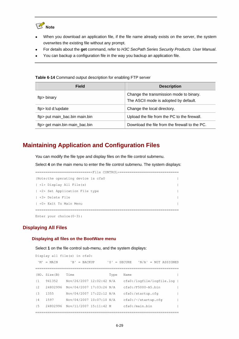
6-29
When you download an application file, if the file name already exists on the server, the system overwrites the existing file without any prompt.
For details about the get command, refer to H3C SecPath Series Security Products User Manual. You can backup a configuration file in the way you backup an application file.
Table 6-14 Command output description for enabling FTP server
Field Description
ftp> binary Change the transmission mode to binary. The ASCII mode is adopted by default.
ftp> lcd d:\update Change the local directory.
ftp> put main_bac.bin main.bin Upload the file from the PC to the firewall.
ftp> get main.bin main_bac.bin Download the file from the firewall to the PC.
Maintaining Application and Configuration Files
You can modify the file type and display files on the file control submenu.
Select 4 on the main menu to enter the file control submenu. The system displays:
===========================<File CONTROL>=============================
|Note:the operating device is cfa0 |
| <1> Display All File(s) |
| <2> Set Application File type |
| <3> Delete File |
| <0> Exit To Main Menu |
======================================================================
Enter your choice(0-3):
Displaying All Files
Displaying all files on the BootWare menu
Select 1 on the file control sub-menu, and the system displays:
Display all file(s) in cfa0:
'M' = MAIN 'B' = BACKUP 'S' = SECURE 'N/A' = NOT ASSIGNED
======================================================================
|NO. Size(B) Time Type Name |
|1 941352 Nov/26/2007 12:02:42 N/A cfa0:/logfile/logfile.log |
|2 24802996 Nov/04/2007 17:03:26 N/A cfa0:/F5000-A5.bin |
|3 1355 Nov/04/2007 17:22:12 N/A cfa0:/startup.cfg |
|4 1597 Nov/04/2007 10:07:10 N/A cfa0:/~/startup.cfg |
|5 24802996 Nov/11/2007 15:11:42 M cfa0:/main.bin |
======================================================================

6-30
Displaying all files at the CLI
<H3C>dir
Directory of cfa0:/
0 drw- - Nov 28 2000 04:09:30 logfile
1 -rw- 24802996 Nov 04 2007 17:03:26 F5000-A5.bin
2 -rw- 1355 Nov 04 2007 17:22:12 startup.cfg
3 -rw- 24802996 Nov 13 2037 13:21:20 main.bin
505480 KB total (456576 KB free)
File system type of cfa0: FAT16
Table 6-15 Output description
Field Description
Directory of cfa0:/ Name of the current directory
505480 KB total (456576 KB free) Used space of the storage medium (available space)
File system type of cfa0: FAT16 File system type of the storage medium
For details about the dir command, refer to H3C SecPath Series Security Products User Manual.
Setting Application Files Attributes
Setting application file attributes on the BootWare menu
You can modify the attributes of the application files on the BootWare menu or using commands; however, you cannot modify the attribute of the secure application file. For details about application file attributes, refer to “Application Files” on page 6-1.
To set the attributes of an application file on the BootWare menu, follow these steps:
Step1 Select 2 on the file control submenu, and the system displays:
'M' = MAIN 'B' = BACKUP 'S' = SECURE 'N/A' = NOT ASSIGNED
======================================================================
|NO. Size(B) Time Type Name |
|1 24802996 Nov/04/2007 17:03:26 B cfa0:/main.bin |
|2 24802996 Nov/11/2007 15:11:42 M cfa0:/main_bak.bin |
|0 Exit |
======================================================================
Enter file no:
Step2 Select the file, 1 for example. The system displays:
Modify the file attribute:
======================================================================

6-31
|<1> +Main |
|<2> -Main |
|<3> +Backup |
|<4> -Backup |
|<0> Exit |
======================================================================
Enter your choice(0-4):
You can set the file attribute to M (main) or B (backup), or cancel the setting. For details about attributes, refer to “Overview” on page 6-1.
In the example, 1 is selected and the system changes the attribute of the file main.bin from B to M + B.
Set the file attribute success!
Now, the attribute of the file main_bak.bin automatically changes from M to N/A.
Setting application file attributes at the CLI
In the following description the files main.bin and main_bak.bin mentioned above are taken as examples.
# Change the attribute of the file main.bin file from B to M + B.
<H3C> boot-loader file main.bin slot 1 main
This command will set the boot file of the specified board. Continue? [Y/N]:
The specified file will be used as the main boot file at the next reboot!
Now the attribute of the file main.bin has changed from B to M + B and the file will be used as the main application file at the next boot, while the attribute of another existing file main_bak.bin has automatically changed from the M to N/A.
You can verify the changes of the file attributes by viewing all the files on the file control submenu.
Select 2 from the file control submenu. The system displays the following information:
'M' = MAIN 'B' = BACKUP 'S' = SECURE 'N/A' = NOT ASSIGNED
======================================================================
|NO. Size(B) Time Type Name |
|1 24802996 Nov/04/2007 17:03:26 M+B cfa0:/main.bin |
|2 24802996 Nov/11/2007 15:11:42 N/A cfa0:/main_bak.bin |
|0 Exit |
======================================================================
Enter file no:
For details about the boot-loader command, refer to H3C SecPath Series Security Products User Manual.

6-32
Deleting a File
Deleting a file on the BootWare menu
Step1 Select 3 from the file control submenu. The following information appears:
Deleting the file in cfa0:
'M' = MAIN 'B' = BACKUP 'S' = SECURE 'N/A' = NOT ASSIGNED
======================================================================
|NO. Size(B) Time Type Name
|1 941352 Nov/26/2000 12:02:42 N/A cfa0:/logfile/logfile.log |
|2 24802996 Nov/04/2007 17:03:26 N/A cfa0:/F5000-A5.bin |
|3 1355 Nov/04/2007 17:22:12 N/A cfa0:/startup.cfg |
|4 1597 Nov/04/2007 10:07:10 N/A cfa0:/~/startup.cfg |
|5 24802996 Nov/11/2055 15:11:42 M cfa0:/main.bin |
|0 Exit |
======================================================================
Enter file no:
Step2 Enter the file number, which is 4 in this example. The following information appears:
The file you selected is cfa0:/~/startup.cfg,Delete it? [Y/N]
Step3 Enter Y.
If the file is deleted successfully, the system displays:
Deleting...........Done!.
Deleting a file at the CLI
You can delete a file using the delete [ /unreserved ] file-url command in user view.
/unreserved: Deletes a file permanently. file-url: Specifies the file to be deleted.
# Delete the file test.txt in the root directory.
<H3C> delete test.txt
Delete cfa0:/test.txt?[Y/N]:y
%Delete file cfa0:/test.txt...Done.
Now, the file test.txt is moved to the recycle bin. If you want to restore the file, you can use the undelete command.
# Restore the file test.txt from the recycle bin.
<H3C> undelete test.txt
Undelete cfa0:/test.txt? [Y/N]:y
% Undeleted file cfa0:/test.txt.

6-33
For details about the delete and undelete commands, refer to H3C SecPath Series Security Products User Manual.
Dealing with Password Loss
When the BootWare password, user password or super password is lost, resort to the following methods:
BootWare Password Loss
Contact your local sales agent to set a new password in the event of BootWare password loss.
The BootWare password is modified on the main menu. To do that, follow these steps:
Step1 Select 5 on the main menu to modify the BootWare password.
The system displays:
please input old password:
Step2 Enter the old password.
please input old password: ******
If the old password is incorrect, the system will display “Wrong password, Please input password again.”
You have three chances to enter the correct old BootWare password. If you fail to enter the correct password for three times, the system will be halted and display “Wrong password, system halt.”
After you enter the correct old password, the system prompts you to enter a new password twice.
Step3 Enter the new password twice at the prompt.
Please input new password: ******
Please input new password again: ******
If the system displays the following information, the password is successfully modified.
Password Set Successfully.

6-34
The BootWare password you entered is displayed in the form of asterisks. The BootWare password can contain up to 32 characters. If you enter more than 32 characters to
set the BootWare password, the system will automatically use the first 32 characters.
Dealing With User Password Loss
If you lose your password, you cannot enter the system. In this case, you can boot the system by skipping the system configuration. Perform the following operations:
Step1 Enter the main menu, and select 6 to boot the system by ignoring the system configuration.
The system displays:
Flag Set Success.
Step2 When the main menu appears again, select 0 to reboot the system.
System is rebooting now.
System start booting...
Booting Normal Extend BootWare....
Step3 Set a new password in system view after system reboot.
<H3C> system-view
[H3C] user-interface console 0
[H3C-ui-console0] authentication-mode password
[H3C-ui-console0] set authentication password simple 123456
The above information indicates that password authentication is adopted on the console interface and the password is set to 123456 and stored in plain text.
After rebooted, the system runs with the initial default configuration, but the original configuration file is still stored in the storage medium. To restore the original configuration, you can use the display saved-configuration command to display it, and then copy and execute it.
If the password is stored in plain text, you can use the display current-configuration command to view the password in the current configuration. If the password 123456 is set with the set authentication password cipher command, the password is stored in cipher text.
Step4 Save the new password.
[H3C] save

6-35
Execute the save command after modifying the user password to save the new password. You are recommended to save the modification to the configuration file used by default.
Dealing With Super Password Loss
The super password enables you to switch between four super levels. In the case of super password loss, you cannot perform higher level operations.
You can clear the super password by selecting 8 on the main menu.
========================<EXTEND-BootWare MENU>========================
|<1> Boot System |
|<2> Enter Serial SubMenu |
|<3> Enter Ethernet SubMenu |
|<4> File Control |
|<5> Modify BootWare Password |
|<6> Skip Current System Configuration |
|<7> BootWare Operation Menu |
|<8> Clear Super Password |
|<9> Storage Device Operation |
|<0> Reboot |
======================================================================
Enter your choice(0-9):8
The system displays the following information indicating that you have successfully cleared the super password.
Clear Application Password Success!
After you clear the super password, quit the menu and reboot the firewall, you can enter system view directly.
This setting (super password clearing) is valid only for the first reboot of the firewall. The super password will be restored after a second reboot.
Backing Up and Restoring BootWare
You can backup and restore BootWare on the BootWare operation submenu.
Select 7 on the main menu to enter the BootWare operation submenu. Refer to “BootWare Operation Submenu” on page 6-9 for details.
6-36
Backing Up the Entire BootWare
To backup the entire BootWare, you need to backup the basic segment and then the extended segment of the BootWare.
Step1 Select 1 on the BootWare operation submenu. The system displays:
Will you backup the Basic BootWare? [Y/N]
Step2 Enter Y. The system displays:
Begin to backup the Basic BootWare....................Done!
At this moment, backup for the basic segment is finished.
The system continues to display:
Will you backup the Extend BootWare? [Y/N]
Step3 Enter Y. The system displays:
Begin to backup the Extend BootWare...............................Done!
The output indicates that backup of the extended segment is finished.
Both the basic and extended segments of the BootWare are backed up to the Flash.
Restoring the Entire BootWare
Step1 Select 2 on the BootWare operation submenu to overwrite the BootWare in the system with the BootWare stored on the flash. To restore the entire BootWare, you need to first restore the basic segment and then the extended segment of the BootWare.
Will you restore the Basic BootWare? [Y/N]
Step2 Entry Y. The system displays:
Begin to restore Normal Basic BootWare................Done!
The output indicates that the basic segment is restored.
The system continues to display:
Will you restore the Extend BootWare? [Y/N]
Step3 Enter Y. The system displays:
Begin to restore Normal Extend BootWare............................Done!
The output indicates that the extended segment is restored.

i
Table of Contents
7 Maintaining Hardware ·······························································································································7-1 Preparing Tools·······································································································································7-1 Precautions ·············································································································································7-1 Structure of the Firewall ··························································································································7-1 Installing and Removing an MPU············································································································7-3
Structure of an MPU························································································································7-3 Installing an MPU ····························································································································7-3 Removing an MPU ··························································································································7-4
Installing and Removing an LPU·············································································································7-5 Structure of LPUs ····························································································································7-5 Installing an LPU ·····························································································································7-7 Removing an LPU ···························································································································7-8
Installing and Removing a Blank Panel ··································································································7-9 Blank Panel Structure······················································································································7-9 Removing a Blank Panel ···············································································································7-10 Installing a Blank Panel ·················································································································7-11
Installing and Removing a Power Module·····························································································7-12 Power Module Structure················································································································7-12 Installing a Power Module ·············································································································7-13 Removing a Power Module ···········································································································7-13
Installing and Removing a Fan Tray ·····································································································7-15 Fan Tray Structure·························································································································7-15 Installing a Fan Tray······················································································································7-15 Removing a Fan Tray ····················································································································7-16
Inserting and Removing a CF Card ······································································································7-18 CF Card and Slot···························································································································7-18 Installing a CF Card·······················································································································7-18 Removing a CF Card·····················································································································7-18
Installing and Removing a Memory Module··························································································7-19 When to Replace a Memory Module ·····························································································7-19 Memory Module Structure ·············································································································7-21 Memory Module Slot······················································································································7-21 Removing a Memory Module ········································································································7-21 Installing a Memory Module ··········································································································7-22
Installing and Removing an Air Filter ····································································································7-23 Function of an Air Filter ·················································································································7-23 Installing an Air Filter ·····················································································································7-23 Removing an Air Filter ···················································································································7-25

7-1
7 Maintaining Hardware
Preparing Tools
Phillips screwdrivers: P1-100mm, P2-150mm, P3-250mm Flat-blade screwdrivers: P4-75mm ESD-preventive wrist straps, ESD-preventive gloves Antistatic bags, antistatic pads
Except an ESD-preventive wrist strap, none of the above installation tools are shipped with the device.
Precautions
Maintain the firewall hardware under the guidance of the local dealer or technical support engineers appointed by H3C.
To avoid injuries, disconnect all power sources from the firewall before maintaining any hardware modules of the firewall.
Always wear an ESD-preventive wrist strap or ESD-preventive gloves when maintaining the firewall hardware. For more information, refer to the section talking about electrostatic discharge prevention in Chapter 3 “Preparing for Installation.”
When installing or removing a demountable module, such as an MPU, an LPU, a memory module, or a CF card, ensure good alignment with the slot and use uniform force to avoid damage to the module.
Put the removed MPU, LPU, memory module, or CF card on an antistatic workbench with the PCB side facing upward or place it in antistatic bags.
When checking or moving a removed MPU, LPU, memory module, or CF card, avoid touching any components on the PCB.
Structure of the Firewall
Figure 7-1 shows the structure of the F5000-A5.

7-2
Figure 7-1 F5000-A5 structure
(1) (2) (3)
(7) (5)(8)(9)(10)
(13)
(6)
(15)
(14)
(12)
(11)
(4) (1) Left mounting bracket (2) MPU (3) Right mounting bracket (4) Chassis handle (5) Weight-bearing warning label (50 kg/110.2 lb.) (6) Fan tray
(7) AC power module (PWR1) (8) Blank panel for PoE power module (reserved PoE slot)
(9) Blank panel for DC power module (PWR2) (10) ESD socket and silkscreen (11) Blank panel for LPU (Slot 4) (12) Blank panel for LPU (Slot 3) (13) Blank panel for LPU (Slot 2) (14) Blank panel for LPU (Slot 1) (15) Cable management bracket

7-3
Installing and Removing an MPU
Structure of an MPU
Figure 7-2 Interior structure of the MPU
(1) Guide pin (2) Left release latch (3) CPU heatsink (4) Memory module and slot (5) Built-in CF card (6) Right release latch (7) Bus connector (8) Power connector (9) RESET button (10) External CF card LED (CF) (11) Run LED (RUN) (12) MPU active/standby state LED (ACT) (13) Alarm LED (ALM) (14) USB 1 state LED (USB1) (15) USB interface 1 (1) (16) External CF card slot (17) USB interface 0 (0) (18) CF card eject button (19) AUX port (AUX) (20) Console port (CONSOLE)
(21) HA port link state LED (LINK) (22) Data reception & transmission LED of the HA port (ACT)
(23) HA port (HA) (10/100/1000BASE-T) (24) Ethernet link state of the management Ethernet port (LINK)
(25) Data reception & transmission LED of the management Ethernet port (ACT)
(26) Management Ethernet port (MANAGEMENT) (10/100/1000BASE-T)
(27) Ejector lever (28) Captive screw
Installing an MPU
Step1 Face the front panel of the firewall.
Step2 Remove the blank panel of slot 0 from the position. For how to remove a blank panel, refer to “Installing and Removing a Blank Panel” on page 7-9.
Step3 Gently and steadily push the MPU into the slot along the slide rails, and then push the ejector levers inward to lock the board in position.

7-4
Figure 7-3 Insert the MPU into the slot
Step4 Fasten the captive screws by turning them clockwise with a Philips screwdriver.
Figure 7-4 Fasten the captive screws
Step5 Turn on the power switch of the firewall if the firewall is powered off.
Step6 After the MPU is powered on, the RUN LED (green) flashes fast (8 Hz). It flashes slowly (1 Hz) after the MPU application is loaded. This means that the MPU runs normally.
The MPU of the firewall is not hot-swappable. For more information about the MPU LED, refer to Chapter 1 “Firewall Overview.”
Removing an MPU
To remove an MPU, reverse the installation procedure.
Step1 Face the front panel of the firewall.
Step2 Loosen the captive screws by turning them counterclockwise with a Philips screwdriver.

7-5
Figure 7-5 Loosen the captive screws
Step3 Pull the two ejector levers at both ends of the MPU outward to release the MPU, and then gently pull the MPU out along the slide rails.
Figure 7-6 Pull out the MPU
To protect the removed MPU, place it in an antistatic bag. If you do not install a new MPU in the slot, install the blank panel to prevent dust from entering the
chassis. For how to install a blank panel, refer to “Installing and Removing a Blank Panel” on page 7-9.
Installing and Removing an LPU
Structure of LPUs
Figure 7-7 and Figure 7-8 illustrate the structure of NSQ1GT8C40 and NSQ1XP20 respectively.
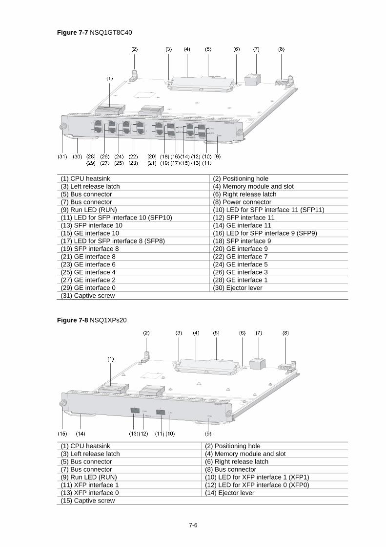
7-6
Figure 7-7 NSQ1GT8C40
(1) CPU heatsink (2) Positioning hole (3) Left release latch (4) Memory module and slot (5) Bus connector (6) Right release latch (7) Bus connector (8) Power connector (9) Run LED (RUN) (10) LED for SFP interface 11 (SFP11) (11) LED for SFP interface 10 (SFP10) (12) SFP interface 11 (13) SFP interface 10 (14) GE interface 11 (15) GE interface 10 (16) LED for SFP interface 9 (SFP9) (17) LED for SFP interface 8 (SFP8) (18) SFP interface 9 (19) SFP interface 8 (20) GE interface 9 (21) GE interface 8 (22) GE interface 7 (23) GE interface 6 (24) GE interface 5 (25) GE interface 4 (26) GE interface 3 (27) GE interface 2 (28) GE interface 1 (29) GE interface 0 (30) Ejector lever (31) Captive screw
Figure 7-8 NSQ1XPs20
(1) CPU heatsink (2) Positioning hole (3) Left release latch (4) Memory module and slot (5) Bus connector (6) Right release latch (7) Bus connector (8) Bus connector (9) Run LED (RUN) (10) LED for XFP interface 1 (XFP1) (11) XFP interface 1 (12) LED for XFP interface 0 (XFP0) (13) XFP interface 0 (14) Ejector lever (15) Captive screw

7-7
Installing an LPU
NSQ1GT8C40 and NSQ1XP20 are installed in the same way. NSQ1GT8C40 is taken as an example here. Follow these steps to install the LPU:
Step1 Face the front panel of the firewall.
Step2 Locate the slot where you will install the LPU (slot 1 through slot 4), and remove the blank panel from the position. For how to remove a blank panel, refer to “Installing and Removing a Blank Panel” on page 7-9.
Step3 Gently push the LPU into the slot along the slide rails until the positioning pin is seated in the positioning hole on the backplane, and then push the ejector levers inward to lock the board in position.
Figure 7-9 Insert the LPU
Step4 Fasten the captive screws on the LPU by turning them clockwise with a Philips screwdriver.
Figure 7-10 Fasten the captive screws
Step5 Turn on the power switch of the firewall if the firewall is powered off.
Step6 After the LPU is powered on, the RUN LED (green) flashes once and then flashes fast (8 Hz). It flashes slowly (1 Hz) after the application is loaded. This means that the LPU runs normally.

7-8
If there is a great resistance when you push an LPU into a slot, first remove the blank panels above and below the slot, then install the LPU, and finally install the removed blank panels to prevent dust from entering the chassis.
Do not insert or remove an LPU when the RUN LED on the LPU is blinking fast. Otherwise, an exception may occur.
LPUs can be installed in slots 1 through 4 of the F5000-A5. The LPUs are powered on in the sequence of slot 1, slot 2, slot 3, and slot 4, with RUN LEDs lighting up in turn.
For more information of the LPU LEDs, refer to Chapter 1 “Firewall Overview.”
Removing an LPU
Follow these steps to remove an LPU:
Step1 Face the front panel of the firewall.
Step2 Locate the LPU to be removed. The figures below illustrate how to remove the LPU in slot 2.
Step3 Loosen the captive screws on the LPU by turning them counterclockwise with a Philips screwdriver.
Figure 7-11 Loosen the captive screws
Step4 Pull the two ejector levers at both ends of the LPU outward to release the LPU, and then gently pull the LPU out along the slide rails.

7-9
Figure 7-12 Pull out the LPU
To protect the removed LPU, place it in an antistatic bag. If you do not install a new LPU in the slot, install a blank panel to prevent dust from entering the
chassis. For how to install a blank panel, refer to “Installing and Removing a Blank Panel” on page 7-9.
Installing and Removing a Blank Panel
Blank Panel Structure
Installed in empty slots on the device, blank panels can prevent dust from entering the firewall chassis.
Two types of blank panels are available in the device:
Blank panel for an MPU/LPU slot Blank panel for a power module slot

7-10
Figure 7-13 Blank panel for an MPU/LPU slot
(1) Front view (2) Side view (3) Oblique rear view (4) EMI gasket
The MPU and LPU slots use the same type of blank panels.
Figure 7-14 Blank panel for a power module slot
(1) Front view (2) Side view (3) Oblique rear view (4) EMI gasket
Removing a Blank Panel
The blank panel for an LPU slot is taken as an example here.
Follow these steps to remove a blank panel:

7-11
Step1 Face the front panel of the firewall.
Step2 Locate the blank panel to be removed, loosen the two captive screws by turning them counterclockwise with a Philips screwdriver. Then, remove the blank panel.
Figure 7-15 Remove a blank panel from an LPU slot
Place the removed blank panels and screws in a safe place for later use. It is recommended to install blank panels in all the empty slots to ensure the normal ventilation in
the firewall.
Installing a Blank Panel
After an LPU is removed from the firewall, it is recommended to install a blank panel if you do not install a new LPU in the slot.
To install a blank panel, reverse the removal procedure.
Step1 Face the front panel of the firewall.
Step2 Locate the slot where you will install a blank panel, cover the blank panel on the slot, and then fasten the captive screws by turning them clockwise with a Philips screwdriver.
Figure 7-16 Install a blank panel in an LPU slot
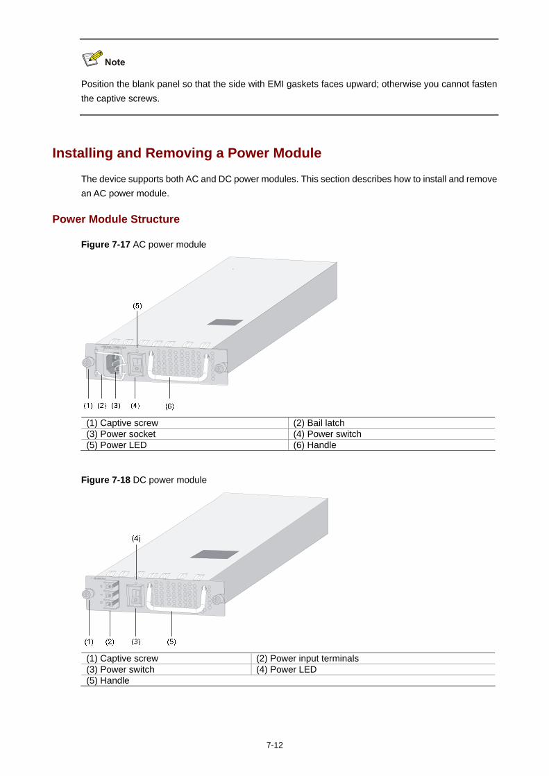
7-12
Position the blank panel so that the side with EMI gaskets faces upward; otherwise you cannot fasten the captive screws.
Installing and Removing a Power Module
The device supports both AC and DC power modules. This section describes how to install and remove an AC power module.
Power Module Structure
Figure 7-17 AC power module
(1) Captive screw (2) Bail latch (3) Power socket (4) Power switch (5) Power LED (6) Handle
Figure 7-18 DC power module
(1) Captive screw (2) Power input terminals (3) Power switch (4) Power LED (5) Handle

7-13
Installing a Power Module
The following describe how to install an AC power module. You can install a DC power module in a similar way.
Step1 Face the front panel of the firewall.
Step2 Locate the slot where the power module is to be installed, insert the power module into the slot, and gently push the power module in along the slide rails.
Figure 7-19 Insert the power module
Step3 Fasten the captive screws on the power module by turning them clockwise with a Philips screwdriver.
Figure 7-20 Fasten the captive screws
Step4 Turn on the power switch of the firewall if the firewall is powered off. The power LED (green) lights up, indicating the power module runs normally.
The device supports online insertion and removal (OIR) of a power module. The device does not support intermixing of AC and DC power modules. When two power modules
are installed in the device, both can work at the same time. When a power module fails, the corresponding power LED turns red.
Removing a Power Module
The following describe how to remove an AC power module. You can remove a DC power module in a similar way.

7-14
Step1 Face the front panel of the firewall.
Step2 Locate the power module to be removed, and loosen the captive screws on the power module by turning them counterclockwise with a Philips screwdriver.
Figure 7-21 Loosen the captive screws
Step3 Gently pull the power module out along the slide rails.
Figure 7-22 Pull out the power module
To protect the removed power module, place it in an antistatic bag. If you do not install a new power module in the slot, install a blank panel to prevent dust from
entering the chassis. For how to install a blank panel, refer to “Installing and Removing a Blank Panel” on page 7-9.

7-15
Installing and Removing a Fan Tray
Fan Tray Structure
Figure 7-23 Fan tray structure
(1) Run LED (RUN) (2) Alarm LED (ALM) (3) Handle (4) Fan (5) CAUTION sign (6) Captive screw
Installing a Fan Tray
Follow these steps to install a fan tray:
Step1 Face the front panel of the firewall.
Step2 Make sure that the texts on the fan tray panel are not upside down; otherwise the fan tray cannot be inserted into the fan tray slot.
Step3 Gently push the fan tray into the slot along the slide rails.
Figure 7-24 Push the fan tray into the slot

7-16
Step4 Fasten the captive screws by turning them clockwise with a Philips screwdriver.
Figure 7-25 Fasten the captive screws
Step5 Turn on the power switch of the firewall if the firewall is powered off. The fan LED RUN (green) lights up, indicating the fans run normally.
The device supports automatic fan speed adjustment. For the description of the fan tray LEDs, refer to Chapter 1 “Firewall Overview.”
Removing a Fan Tray
Keep your hands away from the spinning fan blades when removing the fan tray.
To remove a fan tray, reverse the installation procedure.
Step1 Face the front panel of the firewall.
Step2 Loosen the captive screws on the fan tray by turning them counterclockwise with a Philips screwdriver.

7-17
Figure 7-26 Loosen the captive screws
Step3 Gently pull the fan tray out along the slide rails.
Figure 7-27 Take out the fan tray
Do not keep the firewall working without a fan tray for a long time because poor ventilation may result in damage to the firewall.
To protect the removed fan tray, place it in an antistatic bag.

7-18
Inserting and Removing a CF Card
CF Card and Slot
Figure 7-28 CF card and slot
(1) Eject button (2) CF card slot (3) CF LED
Installing a CF Card
Follow these steps to install a CF card:
Step1 Check whether the CF card LED is blinking. If yes, the system is accessing the CF card. Proceed with the next step after the LED stops blinking.
Step2 Press the CF card eject button in and make sure it does not project from the panel.
Step3 Insert the CF card into the slot and push it all the way in until it is firmly seated.
Figure 7-29 Insert a CF card into the slot
If the application program for booting the firewall is stored in an external CF card, make sure that the right CF card has been correctly installed in the slot; otherwise the firewall will fail to boot.
Removing a CF Card
Follow these steps to remove a CF card:
Step1 Check whether the CF card LED is blinking. If yes, the system is accessing the CF card. Proceed to the next step after the LED stops blinking.
Step2 Press the CF card eject button so that the eject button projects from the panel.

7-19
Figure 7-30 Eject the CF card
Step3 Press the eject button again to eject the CF card part-way out of the slot, and then pull the card out of the slot.
Figure 7-31 Press the eject button to eject the CF card
Do not insert or remove the CF card when the firewall is booting or the LED is blinking to avoid hardware damage.
To protect the removed CF card, place it in an antistatic bag.
Installing and Removing a Memory Module
The MPU and LPUs of the firewall are equipped with memory modules. Before installing or removing a memory module, remove the MPU or LPU from the chassis first. For
details about how to remove an MPU or LPU, refer to ”Installing and Removing an MPU” and "Installing and Removing an LPU."
When to Replace a Memory Module
Memory modules are removable components on the main board.

7-20
You may need to replace a memory module or expand memory in the following situations:
More memory is needed to upgrade the application program. The firewall needs to maintain a large routing table or support memory-demanding operations. The memory module is damaged.
Use the memory modules provided by Hangzhou H3C Technologies Co., Ltd. only. Otherwise, anomalies might occur to the device.
For specific specifications of memory modules supported by the device, refer to the section talking about memory modules in Chapter 1 “Firewall Overview.”
Figure 7-32 presents the procedure of replacing a memory module.
Figure 7-32 Memory module replacement flowchart
Start
Prepare tools
Remove the memory module
Install a new memory module
End
Locate the memory module
Remove the SRPU Remove the LPU
Install the SRPU or LPU
LPUSRPU

7-21
Memory Module Structure
Figure 7-33 Memory module structure
(1) Connector edge (2) Polarization notch (3) Latch notch
Memory Module Slot
Figure 7-34 Memory module slot
(1) Left release latch (2) Memory module slot (3) Right release latch
Removing a Memory Module
Follow these steps to remove a memory module:
Step1 Locate the card (MPU or LPU) to which you will install a memory module and put the card on a flat worktable.
Step2 Pull the release latches away from the memory module at both ends so that the memory module is lifted from the memory module slot.
Step3 Remove the memory module by holding its non-conductive edge.

7-22
Figure 7-35 Remove a memory module
Do not touch the surface-mounted components of the memory module directly with your hands. Hold the memory module only by its non-conductive edge. Because a memory module is vulnerable to ESD, improper operation may cause damage to it.
Do not use too much force in the operation. To protect the removed memory module, place it in an antistatic bag.
Installing a Memory Module
Follow these steps to install a memory module:
Step1 Locate the card (MPU or LPU) to which you will install a memory module, and put the card on a flat worktable.
Step2 Align the polarization notch of the memory module with the key in the connector.
Step3 Insert the memory module into the slot.
Step4 Carefully and firmly press the memory module at both ends until you hear a click. This indicates the memory module is seated in the connector.
Step5 Check that the release latches have firmly locked the memory module in position.
Figure 7-36 Install the memory module

7-23
Do not touch the surface-mounted components of the memory module directly with your hands. Hold the memory module only by its non-conductive edge. Because a memory module is vulnerable to ESD, improper operation may damage it.
Installing and Removing an Air Filter
An air filter is an optional accessory.
Function of an Air Filter
Installed at the left air intake of the device, an air filter prevents dust from entering the chassis.
Installing an Air Filter
Follow these steps to install an air filter:
Step1 Face the left side of the chassis, where the air filter is to be installed.
Step2 Position the upper slide rail horizontally near the top of the left side of the chassis, as shown in Figure 7-37. Align the screw holes on the slide rail with those on the chassis.
Step3 Fasten the fastening screws one by one by turning them clockwise with a Philips screwdriver.
Step4 Position the lower slide rail horizontally near the bottom of the left side of the chassis, as shown in Figure 7-38. Align the screw holes on the slide rail with those on the chassis.
Step5 Fasten the fastening screws one by one by turning them clockwise with a Philips screwdriver.

7-24
Figure 7-37 Install the air filter slide rails
Step6 Gently push the air filter along the slide rails until it is seated in position.
Figure 7-38 Insert the air filter
Step7 Fasten the captive screws by turning them clockwise with a Philips screwdriver.
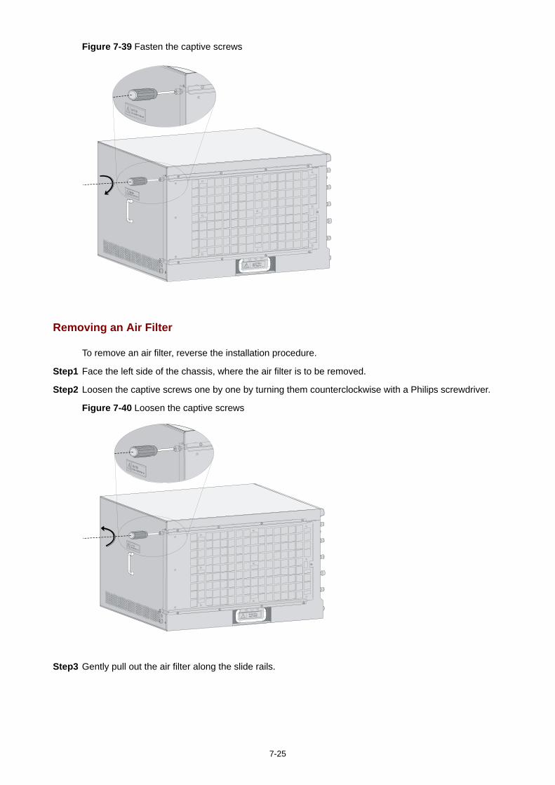
7-25
Figure 7-39 Fasten the captive screws
Removing an Air Filter
To remove an air filter, reverse the installation procedure.
Step1 Face the left side of the chassis, where the air filter is to be removed.
Step2 Loosen the captive screws one by one by turning them counterclockwise with a Philips screwdriver.
Figure 7-40 Loosen the captive screws
Step3 Gently pull out the air filter along the slide rails.

7-26
Figure 7-41 Pull out the air filter
Keep the removed air filter and fastening screws in a safe place for future use. You can clean the air filter with water, but wait until it is completely dry before installing it again.

i
Table of Contents
8 Troubleshooting ········································································································································8-1 Troubleshooting MPU ·····························································································································8-1
Symptom 1 ······································································································································8-1 Symptom 2 ······································································································································8-1 Symptom 3 ······································································································································8-2
Troubleshooting LPUs·····························································································································8-2 Symptom 1 ······································································································································8-2 Symptom 2 ······································································································································8-2
Troubleshooting the Power System········································································································8-3 Symptom 1 ······································································································································8-3 Symptom 2 ······································································································································8-3
Troubleshooting Fans ·····························································································································8-3 Symptom 1 ······································································································································8-3 Symptom 2 ······································································································································8-4
Troubleshooting the Configuration System·····························································································8-4 No Display on the Terminal Screen·································································································8-4 Illegible Characters on the Terminal Screen ···················································································8-4 Serial Port Response Failure ··········································································································8-5
Using the AUX Port as Backup Console Port ·························································································8-5 Password Loss········································································································································8-6 Troubleshooting the Cooling System······································································································8-6 Troubleshooting Application Upgrade·····································································································8-7
Response Failure of the MPU Serial Port ·······················································································8-7 Troubleshooting TFTP Upgrading ···································································································8-7 Troubleshooting FTP Upgrading ·····································································································8-8
Troubleshooting Application File Missing Errors·····················································································8-9

8-1
8 Troubleshooting
The barcode stuck on the firewall chassis contains information about production and servicing. Before you return a faulty firewall for servicing, please provide the barcode information of the firewall to your local sales agent.
Troubleshooting MPU
Symptom 1
Symptom
The RUN LED is off, which indicates the MPU is powered off or faulty. For more information of the RUN LED, refer to Chapter 1 “Firewall Overview.”
Solution
Check that:
The MPU is properly seated in slot 0. The power supply of the firewall is operating properly. The power LED is green when the power
supply works normally.
If the cause cannot be located in the steps above and the problem persists, contact your local sales agent.
Symptom 2
Symptom
Five minutes after the firewall is powered on or the MPU is inserted with power supply on, the RUN LED still fast flashes at 8 Hz, which indicates that the MPU application program failed to start or the MPU is faulty.
Solution
Check that:
The displayed information is correct. The file properties shown in the BootWare menu are correct.
If the cause cannot be located in the steps above and the problem persists, contact your local sales agent.

8-2
Symptom 3
Symptom
The ALM LED is solid on or blinking, which indicates that the firewall is faulty.
For example, the ALM LED is on when the CPU is overheated. The system gives the following message:
%Jun 25 14:38:45:444 2007 H3C DRVMSG/3/TempCritical:
CPU temperature critical in Slot 3, index is 1.
Solution
Check the displayed information (such as system temperature and board voltage alarms) given on the serial terminal and the software management tool.
If cause cannot be located and the problem persists, record the above information and contact your local sales agent.
Troubleshooting LPUs
Symptom 1
Symptom
The RUN LED is off, which indicates the firewall is powered off or the LPU is faulty.
Solution
Check that:
The firewall is powered on. The LPU is properly inserted into an LPU slot (slot 1 through slot 4).
If the LPU is faulty, the following prompt will be displayed after you enter the display version command:
Slot3:
The Board is present, state is unknown
If the cause cannot be located in the steps above and the problem persists, contact your local sales agent.
Symptom 2
Symptom
Twenty minutes after the firewall is powered on or the LPU is inserted with power supply on, the RUN LED still flashes at 8 Hz, which indicates that the LPU application failed to start or the LPU is faulty. In this case, the LPU is in position, and if you enter the display version command, the following information will be displayed:
Slot3:
The Board is present, state is unknown
Solution
Contact your local sales agent.

8-3
Troubleshooting the Power System
Symptom 1
Symptom
The firewall cannot be powered on. The power LED on the front panel is off.
Solution
Check that:
The power switch of the firewall is turned on. The power cord is properly and firmly connected. The power source of the firewall is turned on. The power cord is not damaged.
If the cause cannot be located in the steps above and the problem persists, contact your local sales agent.
Symptom 2
Symptom
The firewall cannot be powered on. The power LED on the front panel is red.
Solution
Check that:
The power module is firmly in place. The power source meets the requirement of the firewall.
If the cause cannot be located in the steps above and the problem persists, contact your local sales agent.
Troubleshooting Fans
Symptom 1
Symptom
After the firewall is booted, the following information appears:
%Jul 5 14:47:20:618 2007 H3C DEV/4/FAN ABSENT:
Fan 1 is absent.
This indicates that the fan tray is not in position.
Solution
Check that:
The fan tray is in position. The fan tray is properly connected with the backplane.
If the cause cannot be located in the steps above and the problem persists, contact your local sales agent.

8-4
Symptom 2
Symptom
When the firewall is running, the ALM LED turns red and the following information appears:
%Jul 5 14:59:03:878 2007 H3C DRVMSG/3/FanPlugIn:Fan 1 Plug In.
%Jul 5 14:59:03:879 2007 H3C DRVMSG/3/FanErr:Fan 1 Error.
#Jul 5 14:59:03:998 2007 H3C DEV/1/FAN STATE CHANGES TO FAILURE:
Trap 1.3.6.1.4.1.2011.2.23.1.12.1.6<fanfailure>: fan ID is 1
%Jul 5 14:59:03:998 2007 H3C DEV/4/FAN FAILED:
Fan 1 failed.
This indicates that fan 1 is faulty.
Solution
Check whether any foreign object has entered the fan tray.
If the cause cannot be located in the steps above and the problem persists, contact your local sales agent.
Troubleshooting the Configuration System
If the system runs normally after the firewall is powered on, the booting information is displayed on the configuration terminal. If the configuration system is faulty, the terminal screen may display nothing or illegible characters.
No Display on the Terminal Screen
Symptom
After the firewall is powered on, the configuration terminal displays nothing.
Solution
Check that:
The power supply is normal. The console cable is properly connected.
If the cause cannot be located in the steps above, the possible reasons are as follows:
The serial port to which the console cable is connected is not the one configured in the emulation program.
Terminal settings are incorrect. The required settings are as follows: 9600 bits per second, 8 data bits, no parity, 1 stop bit, no flow control, and VT100 for terminal emulation type.
The configuration cable is not in good condition.
If the cause cannot be located in the steps above and the problem persists, contact your local sales agent.
Illegible Characters on the Terminal Screen
Symptom
After the firewall is powered on, the configuration terminal displays illegible characters.

8-5
Solution
If the “Data bits” field is set to 5 or 6 in the emulation grogram, illegible characters appear on the screen. Set this field to the default value 8.
Check that the current baud setting is 9600 bps. An incorrect baud setting can cause illegible characters.
Make sure that the work mode of the AUX port is flow when using the AUX port as the backup console port. For more information, refer to "Using the AUX Port as Backup Console Port” on page 8-5.
Serial Port Response Failure
Symptom
The serial port gives no response.
Solution
Check that the cable is in good condition and the serial port settings are correct.
For more information about serial interface settings, refer to the section talking about modifying serial interface parameters in Chapter 6 “Maintaining Software.”
Using the AUX Port as Backup Console Port
When the console port is faulty, you can use the AUX port as the backup console port to complete firewall configuration as follows:
1) Make sure that the work mode of the AUX port is flow. 2) Power off the firewall, connect the RJ-45 connector of the console cable to the AUX port, and then
connect the DB-9 (female) connector to the serial port of the configuration terminal. 3) Power on the firewall.
Username and password are required for AUX port login and the user level should be specified. The AUX port can work in the flow or protocol mode. The AUX port can be used as the backup
console port only when it works in the flow mode. The AUX port works in the flow mode by default. Use the async mod flow | protocol command to switch between the flow mode and the
protocol mode. For more information, refer to H3C SecPath Series Security Products User Manual.

8-6
Password Loss
If you have lost the BootWare password, user password, or super password, refer to the section talking about dealing with password loss in Chapter 6 “Maintaining Software.”
Troubleshooting the Cooling System
Symptom
When the temperature inside the firewall exceeds 75°C (167°F), the following information appears on the configuration terminal screen:
%May 14 21:37:35:271 2007 H3C DRVMSG/3/Temp2High:
Environment temperature too high in Slot 0, index is 2.
#May 14 21:37:35:713 2007 H3C DEV/1/BOARD TEMPERATURE UPPER:
Trap 1.3.6.1.4.1.2011.2.23.1.12.1.16<hwBoaardTemperatureHigher>: frame Index is 0, slot
Index 0.0
%May 14 21:37:35:713 2007 H3C DEV/4/BOARD TEMP TOOHIGH:
Board temperature is too high on Frame 0 Slot 0, type is MPU.
This indicates that the temperature inside the firewall exceeds the upper limit 75°C (167°F). In this case, the fans should run at full speed.
Normally, when the temperature inside the firewall comes down below 75°C (167°F), the following information appears on the configuration terminal screen:
%May 14 22:25:17:804 2000 H3C DRVMSG/3/TempHOK:
Environment temperature recovered from OT in Slot 0, index is 2.
#May 14 22:25:18:713 2000 H3C DEV/1/BOARD TEMPERATURE NORMAL:
Trap 1.3.6.1.4.1.2011.2.23.1.12.1.17<hwBoaardTemperatureFormHigherToNormal>: fr
ameIndex is 0, slotIndex 0.0
%May 14 22:25:18:713 2000 H3C DEV/4/BOARD TEMP NORMAL:
Board temperature changes to normal on Frame 0 Slot 0, type is MPU.
This indicates the temperature in the firewall has come back to the normal range.
If the temperature inside the firewall keeps rising and exceeds 90°C (194°F), the following information appears on the configuration terminal screen:
%Jun 25 14:38:45:444 2007 H3C DRVMSG/3/TempCritical:
CPU temperature critical in Slot 3, index is 1.
The ALM LED of the MPU is red. This indicates that the temperature inside the firewall is abnormal.
Solution
Check that:
The fans are running normally. The working environment of the firewall is well ventilated. Use the display environment command to check whether the temperature in the firewall keeps
rising.

8-7
If the temperature inside the firewall exceeds 90°C (194°F) while the fans are working normally and environment is well ventilated, contact your local sales agent.
For more information about the display environment command, refer to H3C SecPath Series Security Products User Manual.
Troubleshooting Application Upgrade
Response Failure of the MPU Serial Port
Symptom
The MPU serial port gives no response.
Solution
Check that the cable is in good condition and the serial port settings are correct (bits per second is 9600 bps).
For more information about serial port settings, refer to the section talking about modifying serial interface parameters in Chapter 6 “Maintaining Software.”
Troubleshooting TFTP Upgrading
Symptom
During application file upgrading through TFTP, the following problems are encountered:
Symptom 1: The CF card does not have enough space. The following information appears: File will be transferred in binary mode
Downloading file from remote TFTP server, please wait...\
Failed to write data into storage device, maybe no enough space on device
Symptom 2: The file to be downloaded is not found. The following information appears: File will be transferred in binary mode
Downloading file from remote TFTP server, please wait...
File not found.
Symptom 3: The configuration of the network port is incorrect. The following information appears: Can't connect to the remote host

8-8
Solution
For symptom 1: Delete some files in the CF card or use a new CF card so that enough space is available for the application program.
For symptom 2: Type the correct file name. For Symptom 3: Configure the network port correctly. Make sure the network port is up and you can
successfully ping the TFTP server through the network port.
The barcode stuck on the firewall chassis contains information about production and servicing. Before you return a faulty firewall for servicing, please provide the barcode information of the firewall to your local sales agent.
Troubleshooting FTP Upgrading
Symptom
During application upgrading through FTP, the following problems are encountered:
Symptom 1: The CF card does not have enough space. The following information appears: 227 Entering Passive Mode (192,168,1,10,10,204)
150 "xxx" file ready to send (xxx bytes) in ASCII mode
FTP: Error Writing Local File(Screen).
Symptom 2: The file to be downloaded is not found. The following information appears: 227 Entering Passive Mode (192,168,1,10,10,203)
550 Error: File xxx does not exist
FTP: Error Writing Local File(Screen).
Symptom 3: The configuration of the network port is incorrect. The following information appears: FTP: Unrecognized host or wrong IP address!
Solution
For symptom 1: Delete some files in the CF card or use a new CF card so that enough space is available for the application program.
For symptom 2: Type the correct file name. For symptom 3: Configure the network port correctly. Make sure the network port is up and you can
successfully ping the FTP server through the network port.
The barcode stuck on the firewall chassis contains information about production and servicing. Before you return a faulty firewall for servicing, please provide the barcode information of the firewall to your local sales agent.

8-9
Troubleshooting Application File Missing Errors
Symptom
When none of the main, backup, and secure application files exists, the system gives the following message in the startup stage:
BootWare Validating...
Application program does not exist.
Please input BootWare password:
If you select 1 on the BootWare menu, the system displays the following information:
Starting to get the main application file--cfa0:/main.bin!
The main application file does not exist--cfa0:/main.bin!
Starting to get the backup application file--cfa0:/backup.bin!
The backup application file does not exist--cfa0:/backup.bin!
Starting to get the secure application file--cfa0:/secure.bin!
The secure application file does not exist--cfa0:/secure.bin!
Booting App fails!
The names of the main, backup, and secure application files vary with different user settings.
Solution
A possible cause for the above-mentioned phenomena is that the main, backup, and secure application files have been deleted or damaged. You can solve the problem by downloading the application file again or setting the file properties in the BootWare file list.

i
Table of Contents
Appendix A Regulatory Compliance Information ···················································································· A-1 Regulatory compliance standards·········································································································· A-1 European Directives compliance ··········································································································· A-1
LVD/EMC Directive························································································································· A-1 R&TTE Directive····························································································································· A-2 WEEE Directive–2002/96/EC········································································································· A-3
USA regulatory compliance ··················································································································· A-3 FCC Part 15···································································································································· A-3 FDA················································································································································· A-4 California Code of Regulations······································································································· A-4
Canada regulatory compliance ·············································································································· A-4 ICES-003 ········································································································································ A-4
Japan regulatory compliance ················································································································· A-4 VCCI ··············································································································································· A-4
CISPR 22 compliance···························································································································· A-4
Appendix B Safety Information Sicherheits informationen安全信息······················································ B-1 Overview Überblick 概述 ························································································································ B-1
Conventions Used Symbole Erläuterung应用惯例 ········································································· B-2 General Requirements Allgemeine Anforderungen通用要求 ························································· B-3
Electricity Safety Elektrische Sicherheit 用电安全 ················································································· B-4 High Voltage Hochspannung高电压······························································································· B-4 Power Cable Zuleitung电缆 ············································································································ B-5 Thunderstorm Gewitter 防雷击 ······································································································· B-7

A-1
Appendix A Regulatory Compliance Information
Regulatory compliance standards
Table A-1 Regulatory compliance standards
Discipline Standards
EMC
FCC Part 15 (CFR 47) CLASS A ICES-003 CLASS A VCCI-3 CLASS A VCCI-4 CLASS A CISPR 22 CLASS A EN 55022 CLASS A AS/NZS CISPR22 CLASS A CISPR 24 EN 55024 EN 61000-3-2 EN 61000-3-3 EN 61000-6-1 ETSI EN 300 386 EN 301 489-1
Safety
UL 60950-1 CAN/CSA C22.2 No 60950-1 IEC 60950-1 EN 60950-1/A11 AS/NZS 60950 EN 60825-1 EN 60825-2 FDA 21 CFR Subchapter J GB 4943
European Directives compliance
LVD/EMC Directive
This product complies with the European Low Voltage Directive 2006/95/EC and EMC Directive 2004/108/EC.

A-2
R&TTE Directive
This product complies with the European Directive 1999/5/EC
R&TTE declaration statements:
Česky [Czech] H3C Coporation tímto prohlašuje, že tento Router je ve shodě se základními požadavky a dalšími příslušnými ustanoveními směrnice 1999/5/ES.
Dansk [Danish] Undertegnede H3C Corporation erklærer herved, at følgende udstyr Router overholder de væsentlige krav og øvrige relevante krav i direktiv 1999/5/EF.
Deutsch [German]
Hiermit erklärt H3C Corporation, dass sich das Gerät Router in Übereinstimmung mit den grundlegenden Anforderungen und den übrigen einschlägigen Bestimmungen der Richtlinie 1999/5/EG befindet.
Eesti [Estonian] Käesolevaga kinnitab H3C Corporation seadme Router vastavust direktiivi 1999/5/EÜ põhinõuetele ja nimetatud direktiivist tulenevatele teistele asjakohastele sätetele.
English Hereby, H3C Corporation, declares that this Router is in compliance with the essential requirements and other relevant provisions of Directive 1999/5/EC.
Español [Spanish]
Por medio de la presente H3C Corporation declara que el Router cumple con los requisitos esenciales y cualesquiera otras disposiciones aplicables o exigibles de la Directiva 1999/5/CE.
Ελληνική [Greek]
ΜΕ ΤΗΝ ΠΑΡΟΥΣΑ H3C Corporation ΔΗΛΩΝΕΙ ΟΤΙ Router ΣΥΜΜΟΡΦΩΝΕΤΑΙ ΠΡΟΣ ΤΙΣ ΟΥΣΙΩΔΕΙΣ ΑΠΑΙΤΗΣΕΙΣ ΚΑΙ ΤΙΣ ΛΟΙΠΕΣ ΣΧΕΤΙΚΕΣ ΔΙΑΤΑΞΕΙΣ ΤΗΣ ΟΔΗΓΙΑΣ 1999/5/ΕΚ.
Français [French]
Par la présente H3C Corporation déclare que l'appareil Router est conforme aux exigences essentielles et aux autres dispositions pertinentes de la directive 1999/5/CE.
Italiano [Italian] Con la presente H3C Corporation dichiara che questo Router è conforme ai requisiti essenziali ed alle altre disposizioni pertinenti stabilite dalla direttiva 1999/5/CE.
Latviski [Latvian]
Ar šo H3C Corporation deklarē, ka Router atbilst Direktīvas 1999/5/EK būtiskajām prasībām un citiem ar to saistītajiem noteikumiem.
Lietuvių [Lithuanian]
Šiuo H3C Corporation deklaruoja, kad šis Router atitinka esminius reikalavimus ir kitas 1999/5/EB Direktyvos nuostatas.
Nederlands [Dutch]
Hierbij verklaart H3C Corporation dat het toestel Router in overeenstemming is met de essentiële eisen en de andere relevante bepalingen van richtlijn 1999/5/EG.
Malti [Maltese] Hawnhekk, H3C Corporation, jiddikjara li dan Router jikkonforma mal-ħtiġijiet essenzjali u ma provvedimenti oħrajn relevanti li hemm fid-Dirrettiva 1999/5/EC.
Magyar [Hungarian]
Alulírott, H3C Corporation nyilatkozom, hogy a Router megfelel a vonatkozó alapvetõ követelményeknek és az 1999/5/EC irányelv egyéb elõírásainak.
Polski [Polish] Niniejszym H3C Corporation oświadcza, że Router jest zgodny z zasadniczymi wymogami oraz pozostałymi stosownymi postanowieniami Dyrektywy 1999/5/EC.

A-3
Português [Portuguese]
H3C Corporation declara que este Router está conforme com os requisitos essenciais e outras disposições da Directiva 1999/5/CE.
Slovensko [Slovenian]
H3C Corporation izjavlja, da je ta Router v skladu z bistvenimi zahtevami in ostalimi relevantnimi določili direktive 1999/5/ES.
Slovensky [Slovak]
H3C Corporation týmto vyhlasuje, že Router spĺňa základné požiadavky a všetky príslušné ustanovenia Smernice 1999/5/ES.
Suomi [Finnish] H3C Corporation vakuuttaa täten että Router tyyppinen laite on direktiivin 1999/5/EY oleellisten vaatimusten ja sitä koskevien direktiivin muiden ehtojen mukainen.
Svenska [Swedish]
Härmed intygar H3C Corporation att denna Router står I överensstämmelse med de väsentliga egenskapskrav och övriga relevanta bestämmelser som framgår av direktiv 1999/5/EG.
Íslenska [Icelandic]
Hér með lýsir H3C Corporation yfir því að Router er í samræmi við grunnkröfur og aðrar kröfur, sem gerðar eru í tilskipun 1999/5/EC.
Norsk [Norwegian]
H3C Corporation erklærer herved at utstyret Router er i samsvar med de grunnleggende krav og øvrige relevante krav i direktiv 1999/5/EF.
A copy of the signed Declaration of Conformity can be downloaded from:
http://www.h3c.com/portal/Technical_Documents
WEEE Directive–2002/96/EC
The products this manual refers to are covered by the Waste Electrical & Electronic Equipment (WEEE) Directive and must be disposed of in a responsible manner.
USA regulatory compliance
FCC Part 15
This product complies with Part 15 of the FCC Rules. Operation is subject to the following two conditions:
This device may not cause harmful interference. This device must accept any interference received, including interference that may cause
undesired operation.
If the customer modifies the equipment without the authorization of H3C, which directly or indirectly contribute to the equipment incompliance with FCC requirements for Class A digital devices, H3C is not liable for such interference problem and the expenses incurred therefrom shall be covered by the customers.

A-4
This equipment has been tested and found to comply with the limits for a Class A digital device, pursuant to Part 15 of the FCC Rules. These limits are designed to provide reasonable protection against harmful interference when the equipment is operated in a commercial environment. This equipment generates, uses, and can radiate radio frequency energy and, if not installed and used in accordance with the instruction manual, may cause harmful interference to radio communications. Operation of this equipment in a residential area is likely to cause harmful interference in which case the user will be required to correct the interference at his own expense.
FDA
This product Conforms to the applicable requirements of 21 CFR Subchapter J
California Code of Regulations
California Code of Regulations, Title 22, Chapter 33 - Best Management Practices for Perchlorate Materials.
Canada regulatory compliance
ICES-003
This Class [A] digital apparatus complies with Canadian ICES-003.
Cet appareil numérique de la classe [A]est conforme à la norme NMB-003 du Canada.
Japan regulatory compliance
VCCI
This product complies with the requirements of VCCI Class A Information Technology Equipment (ITE).
Warning: If this equipment is used in a domestic environment, radio disturbance may arise. When such trouble occurs, the user may be required to take corrective actions.
CISPR 22 compliance
This product complies with the requirements of CISPR 22 for Class A Information Technology Equipment (ITE).
Warning: If this equipment is used in a domestic environment, radio disturbance may arise. When such trouble occurs, the user may be required to take corrective actions.

B-1
Appendix B Safety Information Sicherheits informationen 安全信息
Overview Überblick 概述
This section introduces part of the safety precautions that should be followed during the installation and maintenance of the equipment. And for the safety statements and warnings, there followed the translations of both German and Chinese to comply with the national requirements.
Dieser Abschnitt macht Sie mit den Sicherheitsvorschriften vertraut, die Sie bei der Installation und Instandhaltung der Ausrüstung beachten müssen.
本章节介绍了在安装、日常维护本系列设备时,必须遵循的安全预防规范。
Before any operation is performed, please read the operation instructions and precautions carefully to minimize the possibility of accidents. The Note, Caution, Warning and Danger items in other manuals do not cover all safety precautions that should be followed. They are only the supplements to the safety precautions for operations as a whole. Therefore, the personnel in charge of the installation and maintenance of the products are required to understand these basics of safety operation. In performing various operations, please follow the local safety regulations. The safety precautions introduced in the product manuals are supplementary and subject to the local safety regulations. When various operations are executed on the products, the precautions and special safety instructions provided with the products must be followed to the full. The personnel in charge of the installation and maintenance of the products must be trained as professionals to master the proper operating methods and all safety precautions. Only the trained and qualified personnel can perform operations such as equipment installation and maintenance.

B-2
Lesen Sie bitte alle Arbeitsanweisungen und Sicherheitvorschriften sorgfältig durch, bevor Sie mit dem Arbeiten beginnen. Nur durch Beachtung dieser Hinweise lässt sich das Unfallrisiko minimieren. Die in anderen Handbüchern aufgeführten Symbole Anmerkung, Achtung, Warnung und Gefahr beinhalten nicht alle zu beachtenden Sicherheitvorschriften. Sie dienen lediglich der Ergänzung. Deshalb muss sich das für die Installation und Instandhaltung der Ausrüstung verantwortliche Personal mit allen Sicherheitshinweise vertraut machen. Bei der Durchführung der verschiedenen Arbeitsschritte müssen außerdem die örtlichen Sicherheitsvorschriften beachtet werden. Die in den Handbüchern der einzelnen Produkte aufgeführten Sicherheitshinweise sind Ergänzungen und unterliegen den nationalen Sicherheitsvorschriften. Während der Arbeit mit den Produkten sind deshalb grundsätzlich alle Sicherheitsvorschriften und spezifischen Sicherheitshinweise genau zu beachten. Das für die Installation und Instandhaltung der Produkte verantwortliche Pesonal muss geschult werden, um alle Sicherheitsvorschriften zu kennen und die richtigen Arbeitsmethoden anwenden zu können. Nur geschultes und qualifiziertes Personal kann die Installation und Instandhaltung in korrekter Weise durchführen.
为了避免可能发生的事故,请在进行任何操作前,仔细阅读设备操作手册和本章节的安全规范。手册中 出现的说明、注意、警告、危险,不能涵盖所有的安全预防,仅仅是在整个操作过程中的安全提示和补充。
因此,负责安装和日常维护本设备的人员必须具备安全操作基本技能。 操作人员要按照当地的安全规范进行操作。出现在产品手册中的安全预防措施仅仅是当地安全规范的补
充。 在操作本设备时,请认真执行产品手册规定的安全规范。 设备安装、维护人员必须通过专业培训,并且掌握足够的操作技能和安规预防意识。只有专业人员才能
担任本设备的安装和维护工作。
Conventions Used Symbole Erläuterung 应用惯例
The symbols in this manual are shown in the following table. They are used to remind the reader of the safety precautions during equipment installation and maintenance.
Die Symbole in diesem Handbuch verwendeten sind in der folgenden Tabelle dargestellt. Diese Symbole sollen das Personal während der Installation und Instandhaltung der Ausrüstung an die Wichtigkeit der im Handbuch aufgeführten Sicherheitsvorschriften erinnern.
以下表格中的安全标识,是用来提示读者在进行设备安装和维护时的安全预防要求。

B-3
Table B-1 Safety symbol and description
Sicherheitssymbole und Beschreibung 安全标识和描述
Safety Symbol Symbole 安全标识
Description Erläuterung
描述
Generic alarm symbol: To suggest a general safety concern Alarm: Hinweis auf ein generelles Sicherheitsproblem 一般注意标识:用于一般安全提示
ESD protection symbol: To suggest electrostatic-sensitive equipment. ESD-Schutz: Hinweis auf Beschädigung infolge elektrostatischer Entladung 防静电标识:用于表示静电敏感的设备
Electric shock symbol: To suggest a danger of high voltage Elektrischer Schlag: Hinweis auf Gefährdung durch Hochspannung 电击防护标识:用于表示高压危险
General Requirements Allgemeine Anforderungen 通用要求
In order to reduce the technically unavoidable residual risk to a minimum, it is imperative to follow the rules below:
Um das technisch bedingte Restrisiko auf ein Minimum zu begrenzen, ist es unbedingt erforderlich, die folgenden Regeln zu beachten:
为了避免对人和设备造成伤害,请认真执行下列要求:
Read all the instructions before operation. Lesen Sie alle Anweisungen sorgfältig durch, bevor Sie mit dem Arbeiten beginnen. 在进行操作前仔细阅读手册内容。 Das System muss in einem Raum installiert werden, der unbefugten Personen keinen Zutritt
gestattet. 设备必须安装在指定位置。 Beachten Sie, dass bei der Installation des Systems stets zuerst die Erdverbindung angebracht
wird und das die Erdverbindung stets als letztes getrennt wird. 进行设备安装时,必须确保接地连接是最先连接和最后断开。 Do not block ventilation openings while the system is on, and keep at least 5 cm distance from
ventilation openings and walls or other things which may block the openings Sorgen Sie dafür, dass die Öffnungen der Ventilation zu keinem Zeitpunkt verschlossen, verstopft
oder anderweitig blockiert sind. Zwischen den Ventilationsöffnungen und Wänden bzw. anderen Gegenständen muss stets ein Abstand von mindestens 5cm bestehen.
设备在工作时必须确保通风口的畅通,确保设备离墙壁或是其它的可能堵塞通风口的物体的间距至
少 5cm。 Never defeat the ground conductor or operate the equipment in the absence of a suitably installed
ground conductor. Contact the appropriate electrical inspection. Betreiben Sie die Ausrüstung niemals ohne Erdung. Trennen Sie das System nicht von der
Erdung. 不允许破坏设备的接地导线或是在无接地连接的情况下操作设备,要进行适当的电气检查。

B-4
The unit/system must be connected to the protection ground before operation permanently. And the cross-section of protective earthing conductor shall be at least 2.5mm2.
Das System muss vor der ständigen Inbetriebnahme geerdet werden. Der Querschnitt der Erdverbindung sollte mindestens 2.5mm2 betragen.
进行设备/系统操作前,请确保永久接地,并且用于进行保护接地连接的接地线截面不小于 2.5mm2。
Electricity Safety Elektrische Sicherheit 用电安全
High Voltage Hochspannung 高电压
High voltage power supply offers electric power for equipment operation. Direct contact or indirect contact (via damp objects) with high voltage and AC mains supply may result in fatal danger.
Die Hochspannungsleitungen stellen für die Arbeit der Ausrüstung erforderliche Energie zur Verfügung. Direkter oder indirekter Kontakt (z. B. durch feuchte Gegenstände) mit Hochspannung und Wechselstromversorgung kann zu tödlichen Unfällen führen.
高压电源为设备运行提供电能,直接或是间接(通过潮湿的物体)接触高压和 AC 交流电源输入,都会
导致致命危险。
During the installation of AC power supply facility, the local safety regulations must be followed. The personnel who install the AC facility must be qualified for high voltage and AC operations.
Bei der Installation der Wechselstromversorgung sind die örtlichen Sicherheitsbestimmungen zu beachten. Das Personal muss besonders qualifiziert sein für das Arbeiten mit Hochspannung und Wechselstrom.
必须按照当地安全规定进行 AC 交流供电设备的安装。负责电源安装的人员必须是通过高压和电源
操作专业培训的专业人员。 Conducting articles, such as watch, hand chain, bracelet and ring are prohibited during the
operation. Es ist nicht erlaubt während dieser Arbeiten leitende Gegenstände wie Uhren, Armbänder,
Armreifen und Ringe am Körper zu tragen. 在操作中不能穿戴导电性的物品,如:手表,手琏,手镯和项链等。 When water is found in the rack, or the rack is damp, please immediately switch off the power
supply. Sollte sich Wasser im Baugruppenträger befinden oder der Baugruppenträger feucht sein, ist die
Energiezufuhr sofort zu unterbrechen und das System abzuschalten.

B-5
当有液体进入机架或机架有损坏时,请立即切断电源。 When operation is performed in a damp environment, make sure that water is kept off the
equipment. Muss in einem feuchten Umgebung gearbeitet werden, ist sicherzustellen, dass kein Wasser in die
Ausrüstung dringen kann. 在潮湿环境下进行安装时,请避免液体进入设备。
Non-standard and improper high voltage operations may result in fire and electric shock. Therefore, AC cable bridging and wiring through a certain area must follow the local rules and regulations. The personnel who perform high voltage operations should be qualified for high voltage and AC operations.
Die Nichtbeachtung der Sicherheitsvorschriften bei der Arbeit mit Hochspannung kann zu Feuer und elektrischem Schlag führen. Deshalb muss die Verlegung von Leitungen und Verbindungen den örtlichen Anforderungen und Sicherheitsvorschriften entsprechen. Arbeiten mit Hochspannung dürfen nur von qualifiziertem Fachpersonal durchgeführt werden.
不规范和不正确的高压电源操作,都会导致失火和电击危险。因此,必须由通过高压和 AC 电源操作专
业培训的专业人员按照当地电气安全规定配置线缆。
Power Cable Zuleitung 电缆
Installation and removal of live power cable is prohibited strictly. Transient contact between the core of power cable and conductor may generate electric arc or spark or electric arc, which may lead to fire or eye injury.

B-6
Das Entfernen und Anbringen von Zuleitungen ist strengstens verboten. Kurzschlüsse zwischen innerem und äußerem Leiter können Lichtbögen oder Funkenflug verursachen, was zu Feuer oder einer Augenverletzung führen kann.
禁止安装和移动带电的线缆。因为导电体和带电的线缆,即使短暂接触,也会引起电火花或电弧,从而
导致失火或是伤害眼睛。
Before the power cable is installed or removed, the power switch must be turned off. Das System muss stets abgeschaltet werden, bevor die Zuleitung angebracht oder entfernt wird. 在安装、移动线缆之前,请切断电源。 Before the power cable is connected, it must be confirmed that the power cable and label comply
with the requirements of the actual installation. Überprüfen Sie vor dem Anbringen der Zuleitung immer, ob das von Ihnen verwendete Kabel den
Anforderungen entspricht. 在进行线缆连接前,请确认线缆和线缆的标识与实际安装要求是一致的。
For DC power supplied equipment, please use 2.5 mm2 minimum power supply cord. For AC power supplied equipment, please use 1.0 mm2 minimum power supply cord.
Für mit Gleichstrom betriebene Ausrüstung benutzen Sie bitte eine 2.5 mm2 Zuleitung. Für mit Wechselstrom betriebene Ausrüstung benutzen Sie bitte eine 1.0 mm2 Zuleitung.
DC 电源设备,请使用 2.5 mm2 电缆; AC 电源设备,请使用 1.0mm2电缆。

B-7
Thunderstorm Gewitter 防雷击
High voltage and AC operations or operations on a steel tower and a mast on a thunderstorm day are prohibited. In order to prevent the equipment from being damaged by lightning, proper grounding is required.
Arbeiten mit Hochspannung und Wechselstrom oder Arbeiten auf Stahltürmen und masten während eines Gewitters sind verboten. Um die Ausrüstung vor Beschädigung durch Blitzschlag zu schützen, ist eine ordnungsgemäße Erdung erforderlich.
禁止在雷雨天进行高压电源和 AC 交流电源安装操作,对金属架和天线的操作也是不允许的。为保护设
备免遭雷击破坏,设备应可靠接地。