H.264 Standalone DVR User Manual
90
H.264 Digital V ideo Recorder Operation Instruction
-
Upload
maxii-ramajo -
Category
Documents
-
view
255 -
download
0
Transcript of H.264 Standalone DVR User Manual
8/10/2019 H.264 Standalone DVR User Manual
http://slidepdf.com/reader/full/h264-standalone-dvr-user-manual 1/90
H.264
Digital Video Recorder
Operation Instruction
8/10/2019 H.264 Standalone DVR User Manual
http://slidepdf.com/reader/full/h264-standalone-dvr-user-manual 2/90
2
Statement:
Copyright ©2011
Any extraction, reproduction or distribution of this manual in part or in
whole by any company or any individual is prohibited without written consent
of our company.
The content of this manual will be updated at any time without notice as a
result of product version upgrade or other reasons. Except otherwise specified,
this manual is only used for application guidance, and all descriptions,
information and recommendation in this manual will not constitute any
expressed or implied warranty.
8/10/2019 H.264 Standalone DVR User Manual
http://slidepdf.com/reader/full/h264-standalone-dvr-user-manual 3/90
3
Precautions:
1. This video recorder is powered by utility power through DC12V adapter, please
check the power supply of power socket to see if it meets the requirement of the
adapter before installation is carried out;
2. Never place the video recorder at humid place or place subject to rain;
3. The video recorder should be installed at a place without strong vibration;
4. The video recorder should be installed at a place without direct sunlight and far
away from heat source and high temperature;
5. When the video recorder is installed, its rear panel should be more than 15cm away
from other object or wall to facilitate heat emission by fan;
6. Allow the video recorder to work within the temperature, humidity, and voltage
ranges permitted by the technical criteria;
7. Never store chemicals from which corrosive and volatile gas may be created in the
place where the video recorder is installed, lest the service life of video recorder will
be affected;
8. The video recorder should not installed where there are many dusts, and the
surrounding environment should be kept clean;
9. When the video recorder is used, correct grounding should be ensured;
10. When the video recorder is installed, correct connection to other devices should be
ensured;
11. Please purchase hard disk from formal channel, so as to suit long term, mass data
read-write requirement of DVR;
8/10/2019 H.264 Standalone DVR User Manual
http://slidepdf.com/reader/full/h264-standalone-dvr-user-manual 4/90
4
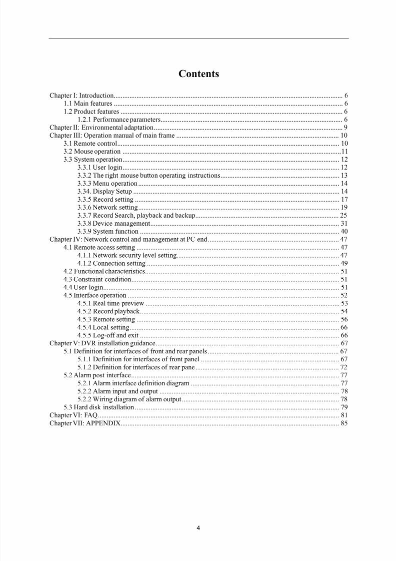
Contents
Chapter I: Introduction................................................................................................................................... 61.1 Main features ................................................................................................................................... 6
1.2 Product features ............................................................................................................................... 6
1.2.1 Performance parameters ........................................................................................................ 6Chapter II: Environmental adaptation ............................................................................................................ 9Chapter III: Operation manual of main frame ............................................................................................. 10
3.1 Remote control ............................................................................................................................... 103.2 Mouse operation ............................................................................................................................. 11
3.3 System operation ............................................................................................................................ 123.3.1 User login ............................................................................................................................ 12
3.3.2 The right mouse button operating instructions .................................................................... 13
3.3.3 Menu operation ................................................................................................................... 143.34. Display Setup ...................................................................................................................... 14
3.3.5 Record setting ..................................................................................................................... 173.3.6 Network setting ................................................................................................................... 19
3.3.7 Record Search, playback and backup.................................................................................. 25
3.3.8 Device management ............................................................................................................ 313.3.9 System function .................................................................................................................. 40
Chapter IV: Network control and management at PC end ........................................................................... 47
4.1 Remote access setting .................................................................................................................... 474.1.1 Network security level setting ............................................................................................. 47
4.1.2 Connection setting .............................................................................................................. 494.2 Functional characteristics ............................................................................................................... 51
4.3 Constraint condition ....................................................................................................................... 51
4.4 User login ....................................................................................................................................... 51
4.5 Interface operation ......................................................................................................................... 524.5.1 Real time preview ............................................................................................................... 534.5.2 Record playback .................................................................................................................. 54
4.5.3 Remote setting .................................................................................................................... 56
4.5.4 Local setting ........................................................................................................................ 664.5.5 Log-off and exit .................................................................................................................. 66
Chapter V: DVR installation guidance ......................................................................................................... 67
5.1 Definition for interfaces of front and rear panels ........................................................................... 675.1.1 Definition for interfaces of front panel ............................................................................... 67
5.1.2 Definition for interfaces of rear pane .................................................................................. 725.2 Alarm post interface ....................................................................................................................... 77
5.2.1 Alarm interface definition diagram ..................................................................................... 77
5.2.2 Alarm input and output ....................................................................................................... 785.2.2 Wiring diagram of alarm output .......................................................................................... 78
5.3 Hard disk installation ..................................................................................................................... 79Chapter VI: FAQ .......................................................................................................................................... 81
Chapter VII: APPENDIX ............................................................................................................................. 85
8/10/2019 H.264 Standalone DVR User Manual
http://slidepdf.com/reader/full/h264-standalone-dvr-user-manual 5/90
5
Foreword
IntroductionThis manual describes a 24/32 channel embedded digital video recorder and its detailed specifications,
details the functions and application precautions for each module of the device, as well as the definitions
for the signals of each connector on the rear panel.
Chapter I Product Introduction. Product functions, main features and environmental adaptation are
briefly introduced.
Chapter II Environmental adaptation.
Chapter III Operation manual of main frame. Including functional introduction for the press keys of
remote control, and the operation function corresponding to each menu interface and the
meaning of each option setting are explained in details.
Chapter IV Remote monitoring software. The operation function corresponding to each IE menu interface
and the meaning of each option setting are explained in details.
Chapter V DVR installation guidance. Signal arrangement and connectors of rear panel are detailed; the
definition for the signal of each external cable; the definition of front panel and the definition
of each interface are also detailed.
Chapter VI FAQ.
8/10/2019 H.264 Standalone DVR User Manual
http://slidepdf.com/reader/full/h264-standalone-dvr-user-manual 6/90
6
Chapter I: Introduction
1.1 Main features
This DVR series is a 4/8/16/24/32 channel real time CIF high resolution digital video recorder. Itfeatures real time monitoring, local recording and playback, supporting 3 bitstreams remote network
monitoring, data backup, parameter setting, supporting motion detection alarm, supporting USB mouse etc
functions.
1.2 Product features
Video compression format is standard H.264
Two USB interfaces
16-bit true color translucent graphic menu interface, menu option notation prompt 24/32 channel synchronous playback
Two-stage user authority management
Support multi-Video real time browse, parameter setting, backup or record playback to
local device by network
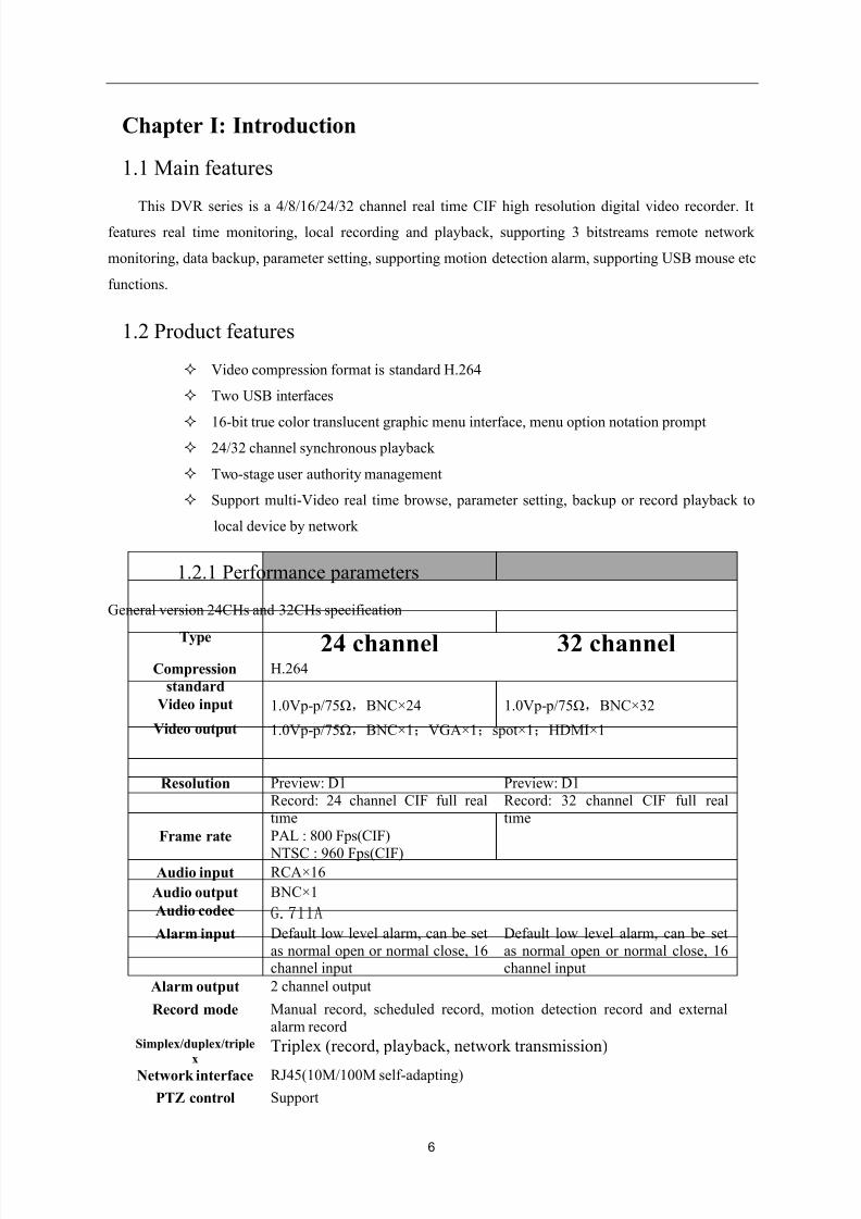
1.2.1 Performance parameters
General version 24CHs and 32CHs specification
Type 24 channel 32 channel
Compression
standard
H.264
Video input 1.0Vp- p/75Ω,BNC×24 1.0Vp- p/75Ω,BNC×32
Video output 1.0Vp- p/75Ω,BNC×1;VGA×1;spot×1;HDMI×1
Resolution Preview: D1
Record: 24 channel CIF full real
time
Preview: D1
Record: 32 channel CIF full real
time
Frame rate PAL : 800 Fps(CIF)
NTSC : 960 Fps(CIF)Audio input RCA×16
Audio output BNC×1
Audio codec G.711A
Alarm input Default low level alarm, can be set
as normal open or normal close, 16channel input
Default low level alarm, can be set
as normal open or normal close, 16channel input
Alarm output 2 channel output
Record mode Manual record, scheduled record, motion detection record and external
alarm recordSimplex/duplex/triple
x Triplex (record, playback, network transmission)
Network interface RJ45(10M/100M self-adapting)
PTZ control Support
8/10/2019 H.264 Standalone DVR User Manual
http://slidepdf.com/reader/full/h264-standalone-dvr-user-manual 7/90
7
Communication
interfaceRS485×1,USB2.0×2,RS232×1
Number of hard
disk4 pieces of high capacity SATA hard disks(300GB-2TB)
Mouse USB mouse
Remote control YesPower supply 12V/6A
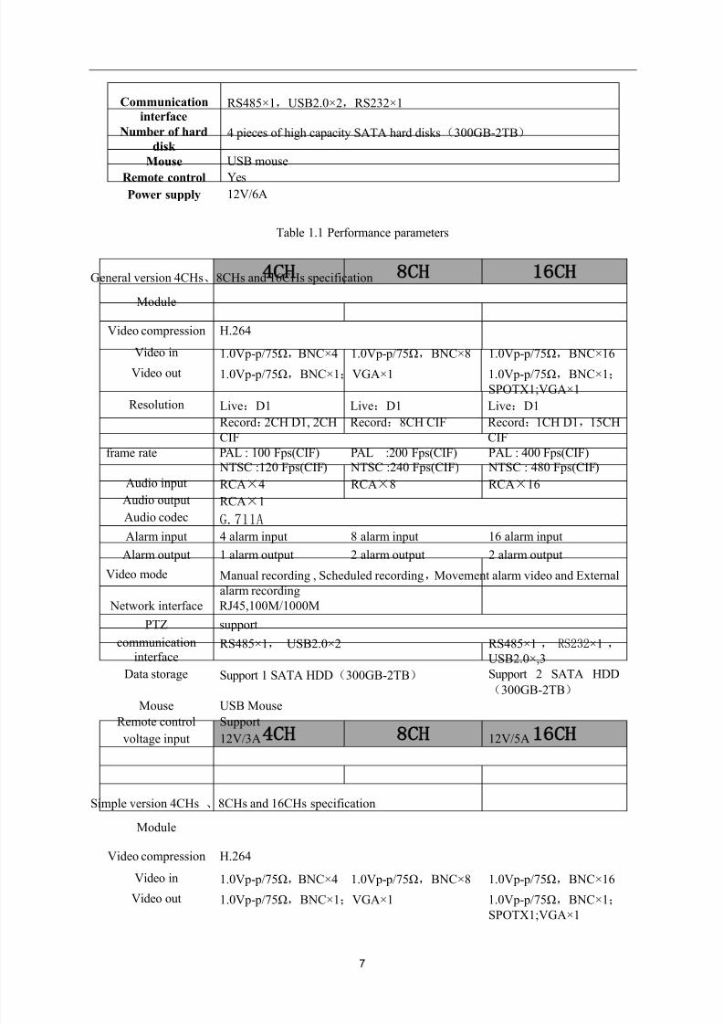
Table 1.1 Performance parameters
General version 4CHs、8CHs and 16CHs specification
Module4CH 8CH 16CH
Video compression H.264
Video in 1.0Vp- p/75Ω,BNC×4 1.0Vp- p/75Ω,BNC×8 1.0Vp- p/75Ω,BNC×16Video out 1.0Vp- p/75Ω,BNC×1;VGA×1 1.0Vp- p/75Ω,BNC×1;
SPOTX1;VGA×1
Resolution Live:D1
Record:2CH D1, 2CH
CIF
Live:D1
Record:8CH CIF
Live:D1
Record:1CH D1,15CH
CIF
frame rate PAL : 100 Fps(CIF) NTSC :120 Fps(CIF)
PAL :200 Fps(CIF) NTSC :240 Fps(CIF)
PAL : 400 Fps(CIF) NTSC : 480 Fps(CIF)
Audio input RCA×4 RCA×8 RCA×16
Audio output RCA×1
Audio codec G.711A
Alarm input 4 alarm input 8 alarm input 16 alarm inputAlarm output 1 alarm output 2 alarm output 2 alarm output
Video mode Manual recording , Scheduled recording,Movement alarm video and External
alarm recording
Network interface RJ45,100M/1000M
PTZ support
communicationinterface
RS485×1, USB2.0×2 RS485×1 , RS232×1 ,
USB2.0×,3
Data storage Support 1 SATA HDD(300GB-2TB) Support 2 SATA HDD
(300GB-2TB)
Mouse USB Mouse
Remote control Support
voltage input 12V/3A 12V/5A
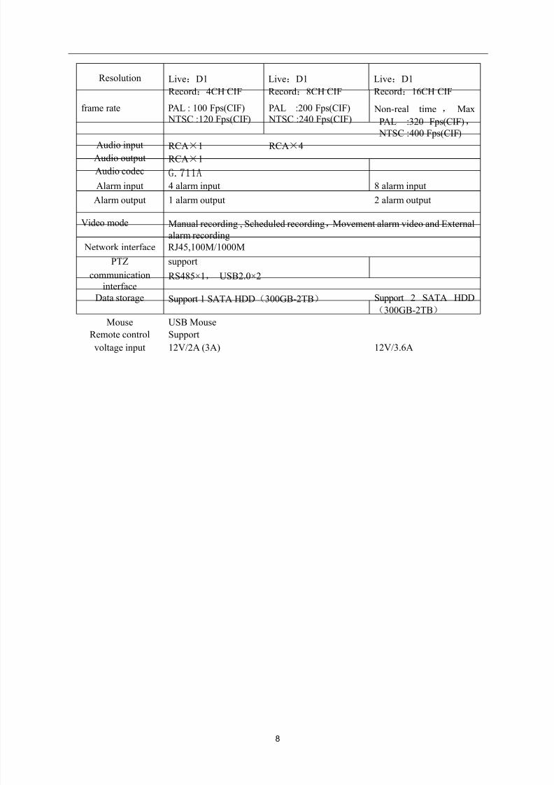
Simple version 4CHs 、8CHs and 16CHs specification
Module4CH 8CH 16CH
Video compression H.264
Video in 1.0Vp- p/75Ω,BNC×4 1.0Vp- p/75Ω,BNC×8 1.0Vp- p/75Ω,BNC×16
Video out 1.0Vp- p/75Ω,BNC×1;VGA×1 1.0Vp- p/75Ω,BNC×1;SPOTX1;VGA×1
8/10/2019 H.264 Standalone DVR User Manual
http://slidepdf.com/reader/full/h264-standalone-dvr-user-manual 8/90
8
Resolution Live:D1
Record:4CH CIF
Live:D1
Record:8CH CIF
Live:D1
Record:16CH CIF
frame rate PAL : 100 Fps(CIF) NTSC :120 Fps(CIF)
PAL :200 Fps(CIF) NTSC :240 Fps(CIF)
Non-real time , Max
PAL :320 Fps(CIF),
NTSC :400 Fps(CIF)Audio input RCA×1 RCA×4
Audio output RCA×1
Audio codec G.711A
Alarm input 4 alarm input 8 alarm input
Alarm output 1 alarm output 2 alarm output
Video mode Manual recording , Scheduled recording,Movement alarm video and External
alarm recording
Network interface RJ45,100M/1000M
PTZ support
communicationinterface
RS485×1, USB2.0×2
Data storage Support 1 SATA HDD(300GB-2TB) Support 2 SATA HDD
(300GB-2TB)
Mouse USB Mouse
Remote control Support
voltage input 12V/2A (3A) 12V/3.6A
8/10/2019 H.264 Standalone DVR User Manual
http://slidepdf.com/reader/full/h264-standalone-dvr-user-manual 9/90
9
Chapter II: Environmental adaptation
In order to ensure safe application of DVR and obtain satisfactory service performance, prolong the
service life of device, customer should fully consider the following factors when install the device:
1) When the device is installed and operated, all specifications of electronic product and the
requirements of vehicle and other connecting device should be followed.
2) Power supply and grounding:
Never use wet hand to touch power supply and video recorder.
Never drop liquid on video recorder, otherwise short circuit inside device or fire may be resulted.
Never pile other object on video recorder.
Use soft dry cloth to clean video recorder, never use chemical solvents.
After the power cable of video recorder is connected to power socket, there is still voltage inside
the device even if the video recorder has not been started.
If the device is not to be used for long term, it is preferred to fully disconnect the power supply of
video recorder, and unplug the power cable from the power socket.
8/10/2019 H.264 Standalone DVR User Manual
http://slidepdf.com/reader/full/h264-standalone-dvr-user-manual 10/90
10
Chapter III: Operation manual of main frame
In the operation of this device, the Enter key on remote control has the same function as the left click of
mouse.
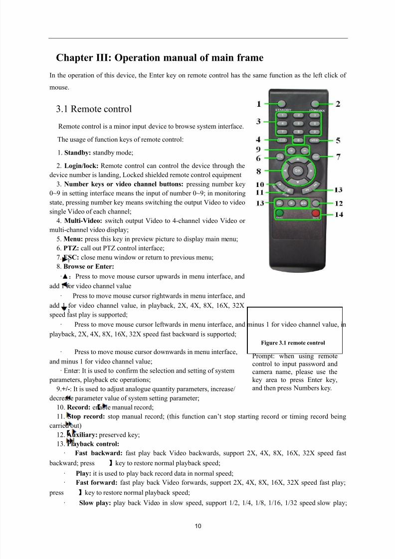
3.1 Remote control
Remote control is a minor input device to browse system interface.
The usage of function keys of remote control:
1. Standby: standby mode;
2. Login/lock: Remote control can control the device through the
device number is landing, Locked shielded remote control equipment
3. Number keys or video channel buttons: pressing number key
0~9 in setting interface means the input of number 0~9; in monitoringstate, pressing number key means switching the output Video to video
single Video of each channel;
4. Multi-Video: switch output Video to 4-channel video Video or
multi-channel video display;
5. Menu: press this key in preview picture to display main menu;
6. PTZ: call out PTZ control interface;
7. ESC: close menu window or return to previous menu;
8. Browse or Enter:
·▲:Press to move mouse cursor upwards in menu interface, and
add 1 for video channel value
· :
Press to move mouse cursor rightwards in menu interface, and
add 1 for video channel value, in playback, 2X, 4X, 8X, 16X, 32X
speed fast play is supported;
· :Press to move mouse cursor leftwards in menu interface, and minus 1 for video channel value, in
playback, 2X, 4X, 8X, 16X, 32X speed fast backward is supported;
Figure 3.1 remote control
· :Press to move mouse cursor downwards in menu interface,
and minus 1 for video channel value;
· Enter: It is used to confirm the selection and setting of system
parameters, playback etc operations;
9.+/-: It is used to adjust analogue quantity parameters, increase/decrease parameter value of system setting parameter;
10. Record: enable manual record;
11. Stop record: stop manual record; (this function can’t stop starting record or timing record being
carried out)
12. Auxiliary: preserved key;
13. Playback control:
· Fast backward: fast play back Video backwards, support 2X, 4X, 8X, 16X, 32X speed fast
backward; press 】key to restore normal playback speed;
· Play: it is used to play back record data in normal speed;
· Fast forward: fast play back Video forwards, support 2X, 4X, 8X, 16X, 32X speed fast play;
press 】key to restore normal playback speed;
· Slow play: play back Video in slow speed, support 1/2, 1/4, 1/8, 1/16, 1/32 speed slow play;
Prompt: when using remotecontrol to input password andcamera name, please use the
key area to press Enter key,
and then press Numbers key.
8/10/2019 H.264 Standalone DVR User Manual
http://slidepdf.com/reader/full/h264-standalone-dvr-user-manual 11/90
11
press
】key to restore normal playback speed;
· Pause/play frame by frame: pause or play back Video frame by frame; press firstly to pause
the playback of Video; then press continuously, each press will play back 1 frame of Video; press 】key
to restore normal playback speed;
14. Sound control: enable and disable sound.Select device number setting by remote control: after 【Login/lock 】key is pressed, input device
number in【Password setting】to control the device. For example: select the device with device number of
“000001”. After 【Login/lock 】key is pressed, input number “1” (that is【Login/lock 】+1), then the remote
control can control the machine with device number of “000001”.
Note: when the device number is 000000, the remote control can control by default,
【Login/lock 】+0, the remote control can control machine with any number
The number of machine can be set as up to 000255
3.2 Mouse operation
Mouse is the main input device to browse system menu.
Note: except stated otherwise, all system functions in this manual are described by using mouse input
operation.
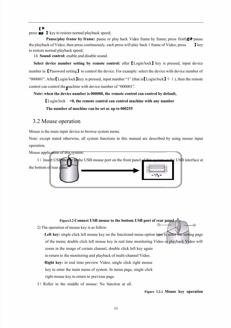
Mouse application of this system:
1)Insert USB mouse to the USB mouse port on the front panel of this system or the USB interface at
the bottom of rear panel.
Figure3.2 Connect USB mouse to the bottom USB port of rear panel
2) The operation of mouse key is as follow:
·Left key: single click left mouse key on the functional menu option icon to enter the setting page
of the menu; double click left mouse key in real time monitoring Video or playback Video will
zoom in the image of certain channel, double click left key again
to return to the monitoring and playback of multi-channel Video.
·Right key: in real time preview Video, single click right mouse
key to enter the main menu of system. In menu page, single click
right mouse key to return to previous page.
3)Roller in the middle of mouse: No function at all.
Figure 3.2.1 Mouse key operation
8/10/2019 H.264 Standalone DVR User Manual
http://slidepdf.com/reader/full/h264-standalone-dvr-user-manual 12/90
12
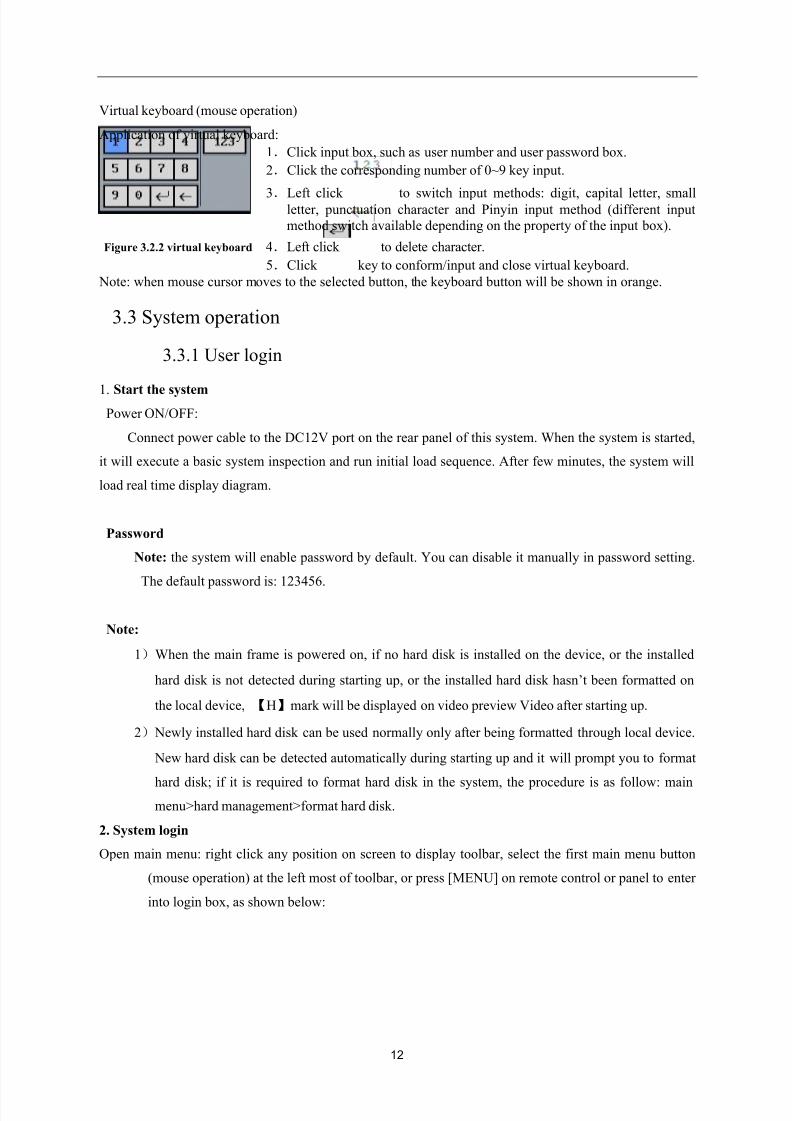
Virtual keyboard (mouse operation)
Application of virtual keyboard:
1.Click input box, such as user number and user password box.
2.Click the corresponding number of 0~9 key input.
3.Left click to switch input methods: digit, capital letter, smallletter, punctuation character and Pinyin input method (different input
method switch available depending on the property of the input box).
Figure 3.2.2 virtual keyboard 4.Left click to delete character.
5.Click key to conform/input and close virtual keyboard.
Note: when mouse cursor moves to the selected button, the keyboard button will be shown in orange.
3.3 System operation
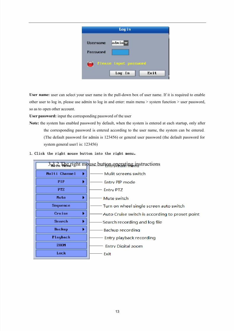
3.3.1 User login
1. Start the system Power ON/OFF:
Connect power cable to the DC12V port on the rear panel of this system. When the system is started,
it will execute a basic system inspection and run initial load sequence. After few minutes, the system will
load real time display diagram.
Password
Note: the system will enable password by default. You can disable it manually in password setting.
The default password is: 123456.
Note:
1)When the main frame is powered on, if no hard disk is installed on the device, or the installed
hard disk is not detected during starting up, or the installed hard disk hasn’t been formatted on
the local device, 【H】mark will be displayed on video preview Video after starting up.
2) Newly installed hard disk can be used normally only after being formatted through local device.
New hard disk can be detected automatically during starting up and it will prompt you to format
hard disk; if it is required to format hard disk in the system, the procedure is as follow: mainmenu>hard management>format hard disk.
2. System login
Open main menu: right click any position on screen to display toolbar, select the first main menu button
(mouse operation) at the left most of toolbar, or press [MENU] on remote control or panel to enter
into login box, as shown below:
8/10/2019 H.264 Standalone DVR User Manual
http://slidepdf.com/reader/full/h264-standalone-dvr-user-manual 13/90
13
User name: user can select your user name in the pull-down box of user name. If it is required to enable
other user to log in, please use admin to log in and enter: main menu > system function > user password,
so as to open other account.
User password: input the corresponding password of the user
Note: the system has enabled password by default, when the system is entered at each startup, only after
the corresponding password is entered according to the user name, the system can be entered.
(The default password for admin is 123456) or general user password (the default password for
system general user1 is: 123456)
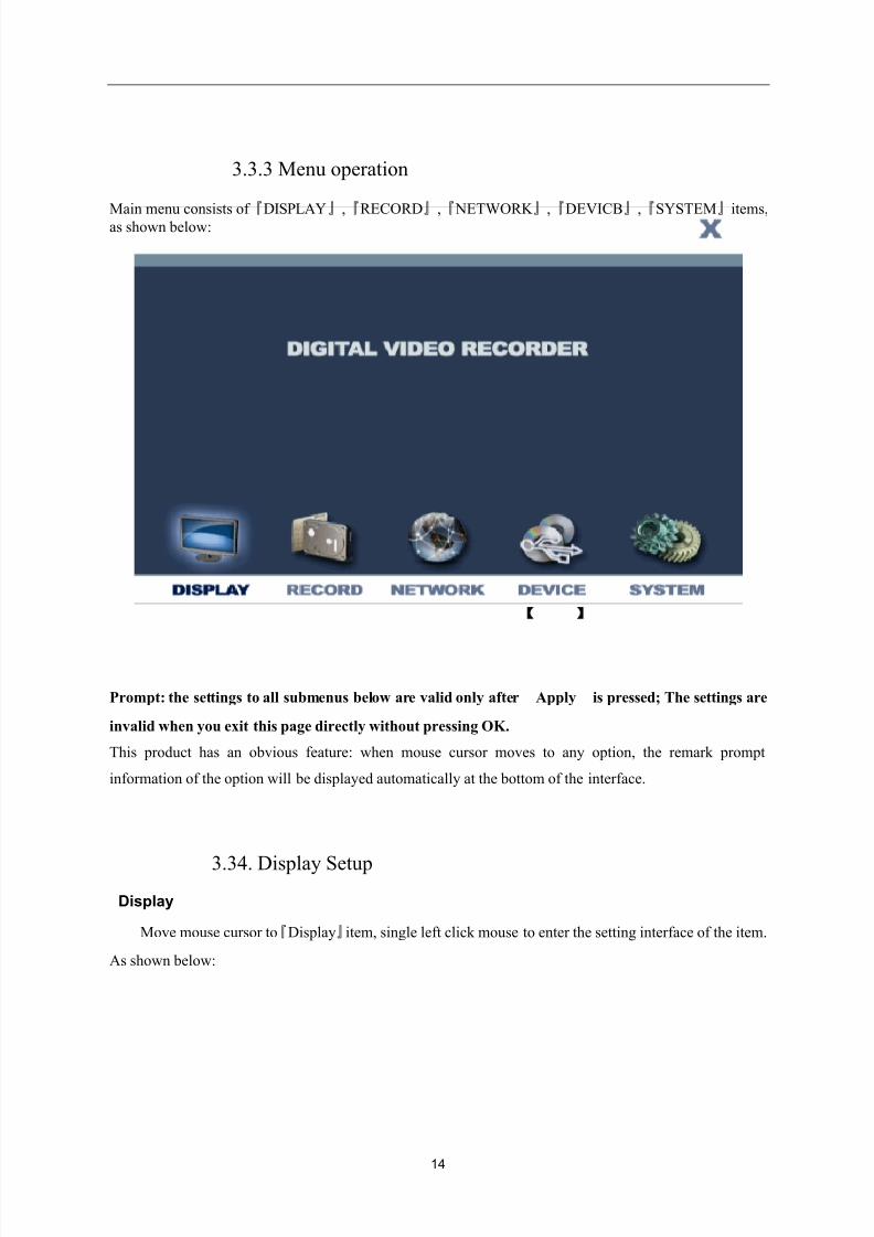
3.3.2 The right mouse button operating instructions
1.
Click the right mouse button into the right menu
8/10/2019 H.264 Standalone DVR User Manual
http://slidepdf.com/reader/full/h264-standalone-dvr-user-manual 14/90
14
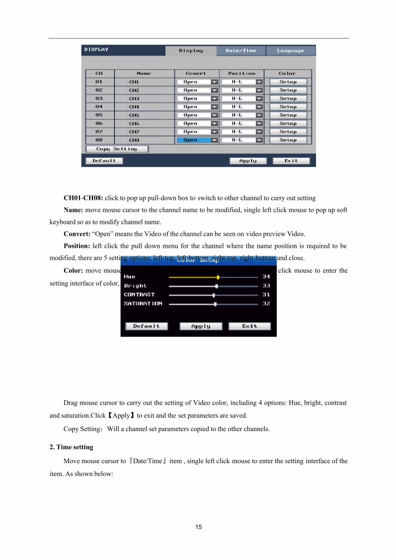
3.3.3 Menu operation
Main menu consists of 『
DISPLAY』
,『
RECORD』
,『
NETWORK 』
,『
DEVICB』
,『
SYSTEM』
items,as shown below:
Prompt: the settings to all submenus below are valid only after Apply】 is pressed; The settings are
invalid when you exit this page directly without pressing OK.
This product has an obvious feature: when mouse cursor moves to any option, the remark prompt
information of the option will be displayed automatically at the bottom of the interface.
3.34. Display Setup
Display
Move mouse cursor to『Display』item, single left click mouse to enter the setting interface of the item.
As shown below:
8/10/2019 H.264 Standalone DVR User Manual
http://slidepdf.com/reader/full/h264-standalone-dvr-user-manual 15/90
15
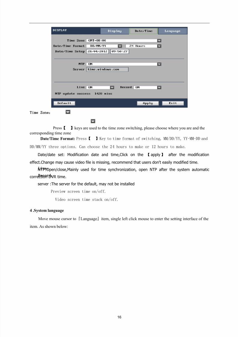
CH01-CH08: click to pop up pull-down box to switch to other channel to carry out setting
Name: move mouse cursor to the channel name to be modified, single left click mouse to pop up soft
keyboard so as to modify channel name.
Convert: “Open” means the Video of the channel can be seen on video preview Video.
Position: left click the pull down menu for the channel where the name position is required to be
modified, there are 5 setting options: left-top, left-bottom, right-top, right-bottom and close.
Color: move mouse cursor the【Setup】of corresponding channel, single click mouse to enter the
setting interface of color, as shown below:
Drag mouse cursor to carry out the setting of Video color, including 4 options: Hue, bright, contrast
and saturation.Click 【Apply】to exit and the set parameters are saved.
Copy Setting:Will a channel set parameters copied to the other channels.
2. Time setting
Move mouse cursor to『Date/Time』item , single left click mouse to enter the setting interface of the
item. As shown below:
8/10/2019 H.264 Standalone DVR User Manual
http://slidepdf.com/reader/full/h264-standalone-dvr-user-manual 16/90
16
Time Zone:Press【 】keys are used to the time zone switching, please choose where you are and the
corresponding time zone
Date/Time Format: Press【 】Key to time format of switching, MM/DD/YY, YY-MM-DD and
DD/MM/YY three options. Can choose the 24 hours to make or 12 hours to make.
Date/date set: Modification date and time,Click on the 【 apply 】 after the modification
effect.Change may cause video file is missing, recommend that users don't easily modified time.
NTP:Open/close,Mainly used for time synchronization, open NTP after the system automatic
correction DVR time.
server :The server for the default, may not be installed
Live
:Preview screen time on/off.
Record:Video screen time stack on/off.
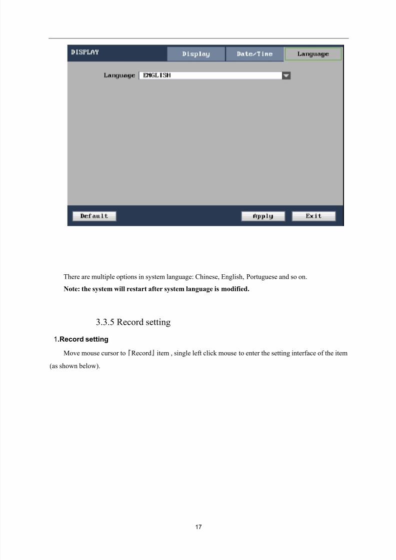
4 .System language
Move mouse cursor to『Language』item, single left click mouse to enter the setting interface of the
item. As shown below:
8/10/2019 H.264 Standalone DVR User Manual
http://slidepdf.com/reader/full/h264-standalone-dvr-user-manual 17/90
17
There are multiple options in system language: Chinese, English, Portuguese and so on.
Note: the system will restart after system language is modified.
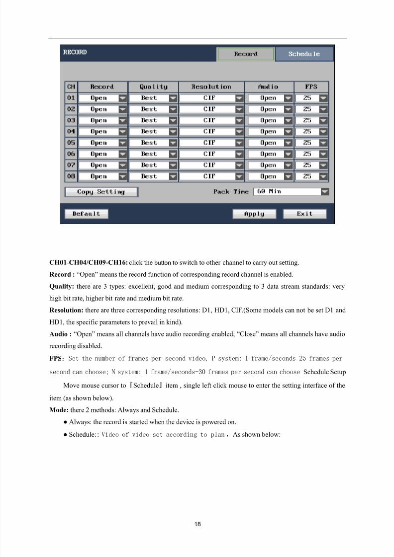
3.3.5 Record setting
1.Record setting
Move mouse cursor to『Record』item , single left click mouse to enter the setting interface of the item
(as shown below).
8/10/2019 H.264 Standalone DVR User Manual
http://slidepdf.com/reader/full/h264-standalone-dvr-user-manual 18/90
18
CH01-CH04/CH09-CH16: click the button to switch to other channel to carry out setting.
Record : “Open” means the record function of corresponding record channel is enabled.
Quality: there are 3 types: excellent, good and medium corresponding to 3 data stream standards: very
high bit rate, higher bit rate and medium bit rate.
Resolution: there are three corresponding resolutions: D1, HD1, CIF.(Some models can not be set D1 and
HD1, the specific parameters to prevail in kind).
Audio : “Open” means all channels have audio recording enabled; “Close” means all channels have audio
recording disabled.
FPS:Set the number of frames per second video, P system: 1 frame/seconds-25 frames per
second can choose; N system: 1 frame/seconds-30 frames per second can chooseSchedule Setup
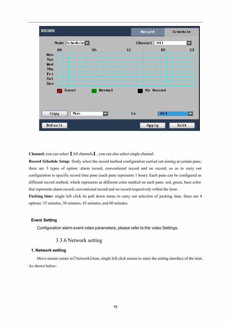
Move mouse cursor to『Schedule』item , single left click mouse to enter the setting interface of the
item (as shown below).
Mode: there 2 methods: Always and Schedule.
● Always: the record is started when the device is powered on.
● Schedule:: Video of video set according to plan,As shown below:
8/10/2019 H.264 Standalone DVR User Manual
http://slidepdf.com/reader/full/h264-standalone-dvr-user-manual 19/90
19
Channel: you can select【All channels】, you can also select single channel.
Record Schedule Setup: firstly select the record method configuration carried out aiming at certain pane;
there are 3 types of option: alarm record, conventional record and no record; so as to carry out
configuration to specific record time pane (each pane represents 1 hour). Each pane can be configured as
different record method, which represents as different color marked on each pane: red, green, base color
that represents alarm record, conventional record and no record respectively within the hour.
Packing time: single left click its pull down menu to carry out selection of packing time, there are 4
options: 15 minutes, 30 minutes, 45 minutes, and 60 minutes.
Event Setting
Configuration alarm event video parameters, please refer to the video Settings.
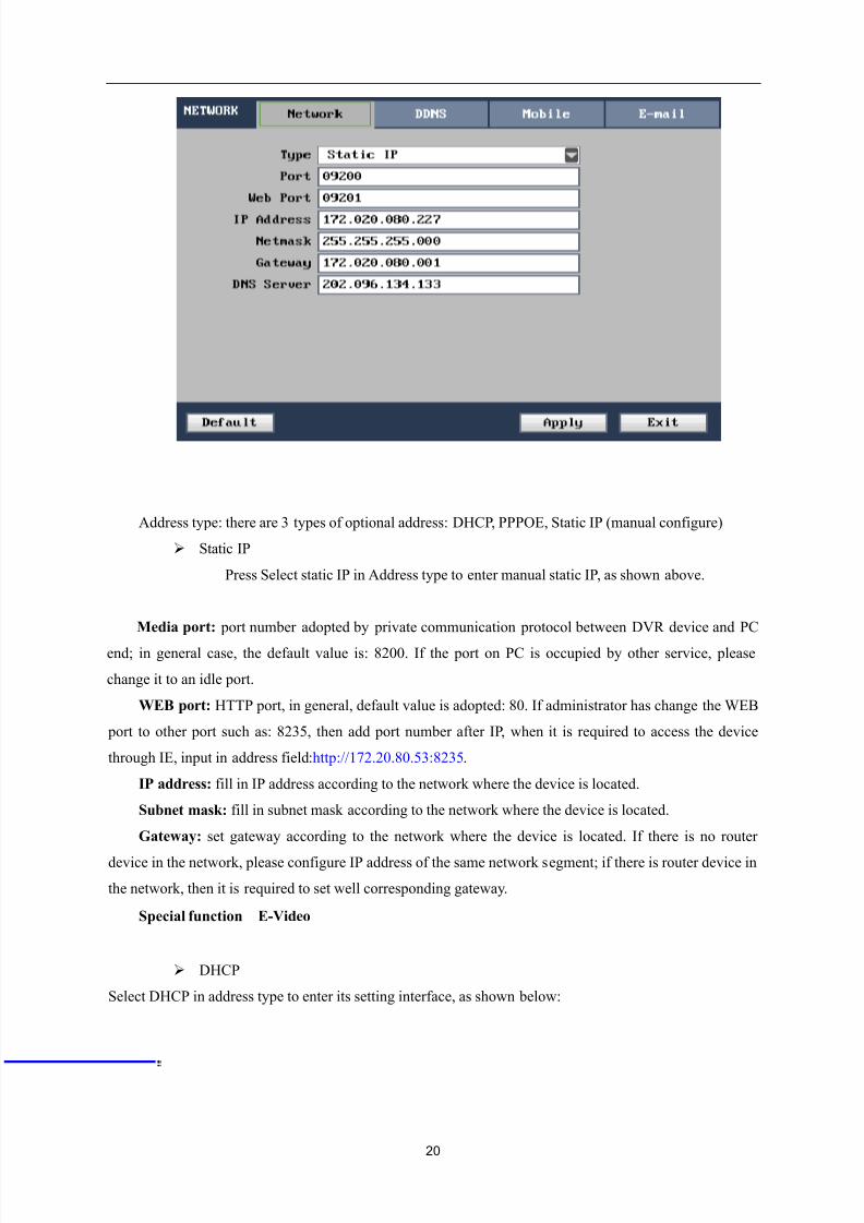
3.3.6 Network setting
1. Network setting
Move mouse cursor to『 Network 』item, single left click mouse to enter the setting interface of the item.
As shown below:
8/10/2019 H.264 Standalone DVR User Manual
http://slidepdf.com/reader/full/h264-standalone-dvr-user-manual 20/90
20
Address type: there are 3 types of optional address: DHCP, PPPOE, Static IP (manual configure)
Static IP
Press Select static IP in Address type to enter manual static IP, as shown above.
Media port: port number adopted by private communication protocol between DVR device and PC
end; in general case, the default value is: 8200. If the port on PC is occupied by other service, please
change it to an idle port.
WEB port: HTTP port, in general, default value is adopted: 80. If administrator has change the WEB
port to other port such as: 8235, then add port number after IP, when it is required to access the device
through IE, input in address field:http://172.20.80.53:8235.
IP address: fill in IP address according to the network where the device is located.
Subnet mask: fill in subnet mask according to the network where the device is located.
Gateway: set gateway according to the network where the device is located. If there is no router
device in the network, please configure IP address of the same network segment; if there is router device in
the network, then it is required to set well corresponding gateway.
Special function:E-Video
DHCP
Select DHCP in address type to enter its setting interface, as shown below:
8/10/2019 H.264 Standalone DVR User Manual
http://slidepdf.com/reader/full/h264-standalone-dvr-user-manual 21/90
21
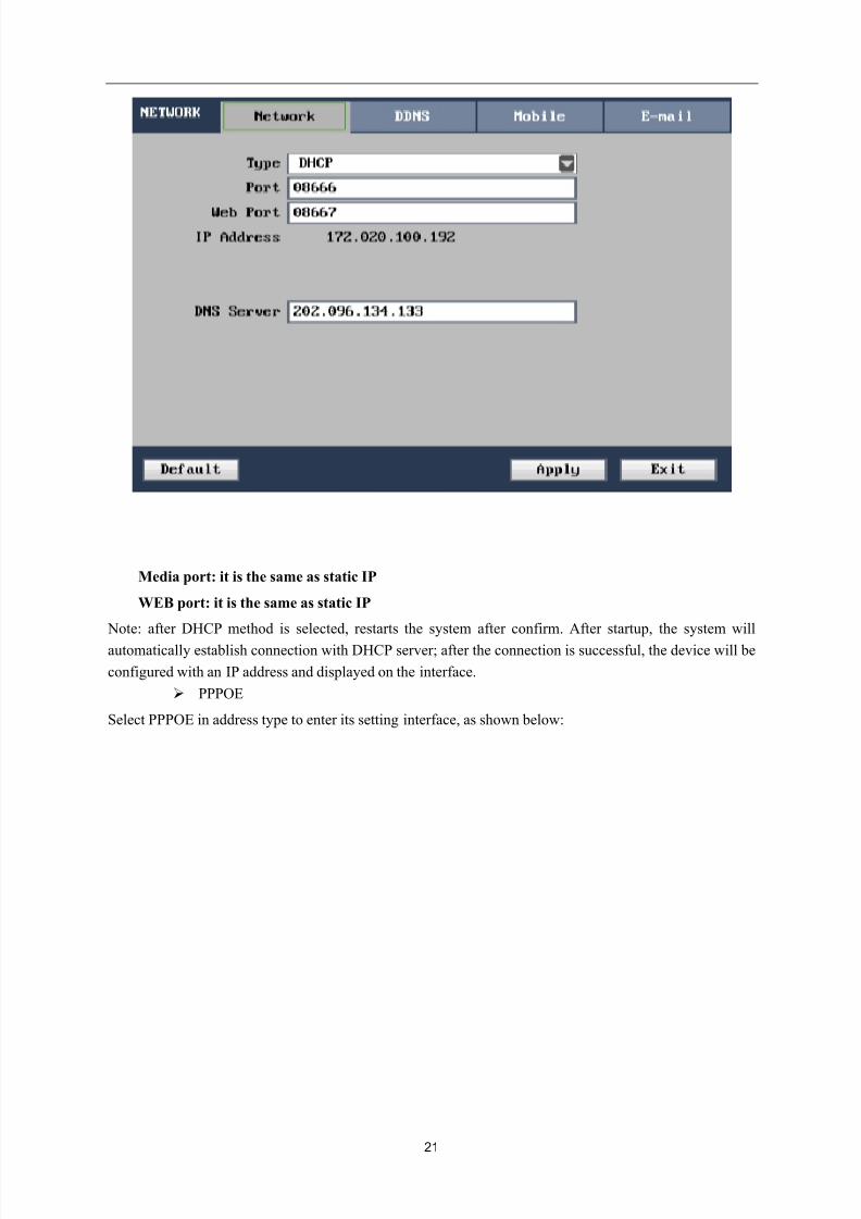
Media port: it is the same as static IP
WEB port: it is the same as static IP
Note: after DHCP method is selected, restarts the system after confirm. After startup, the system will
automatically establish connection with DHCP server; after the connection is successful, the device will be
configured with an IP address and displayed on the interface.
PPPOE
Select PPPOE in address type to enter its setting interface, as shown below:
8/10/2019 H.264 Standalone DVR User Manual
http://slidepdf.com/reader/full/h264-standalone-dvr-user-manual 22/90
22
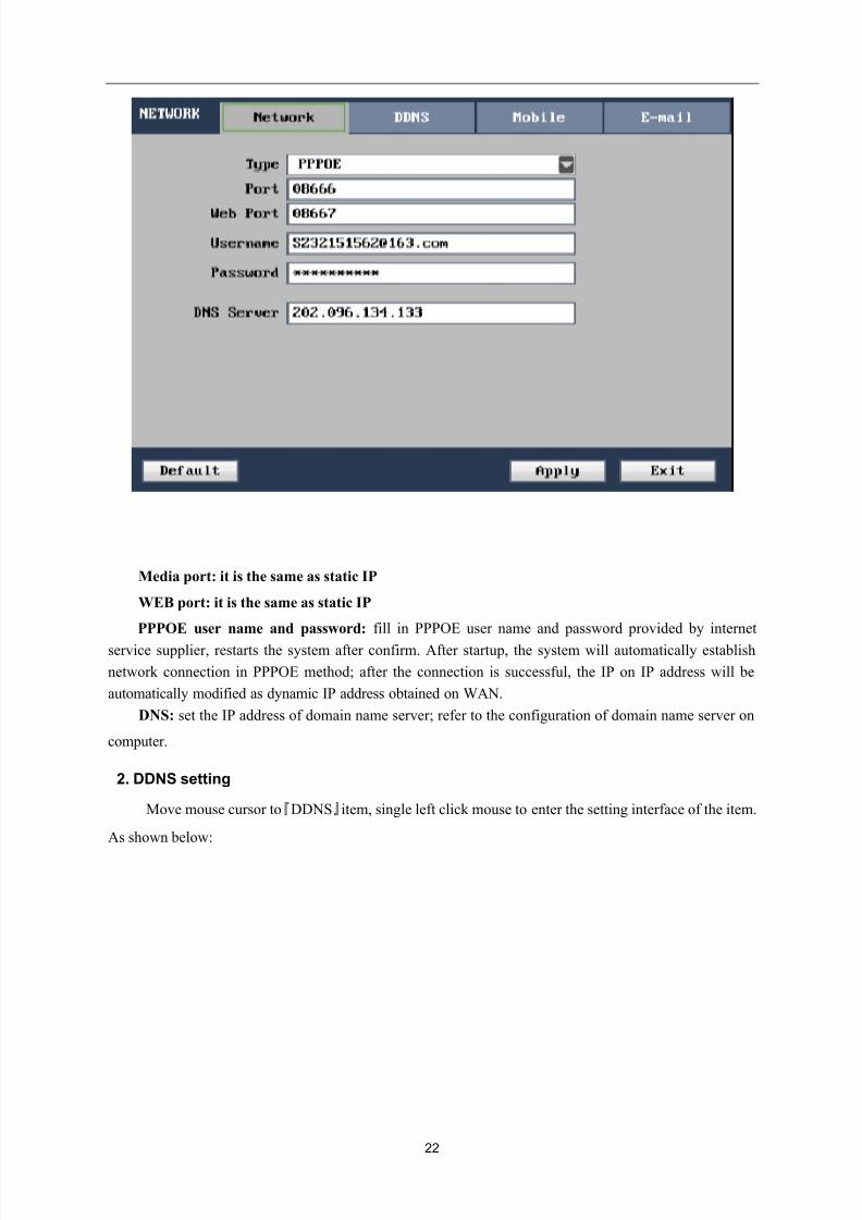
Media port: it is the same as static IP
WEB port: it is the same as static IP
PPPOE user name and password: fill in PPPOE user name and password provided by internet
service supplier, restarts the system after confirm. After startup, the system will automatically establish
network connection in PPPOE method; after the connection is successful, the IP on IP address will be
automatically modified as dynamic IP address obtained on WAN.
DNS: set the IP address of domain name server; refer to the configuration of domain name server on
computer.
2. DDNS setting
Move mouse cursor to『DDNS』item, single left click mouse to enter the setting interface of the item.
As shown below:
8/10/2019 H.264 Standalone DVR User Manual
http://slidepdf.com/reader/full/h264-standalone-dvr-user-manual 23/90
8/10/2019 H.264 Standalone DVR User Manual
http://slidepdf.com/reader/full/h264-standalone-dvr-user-manual 24/90
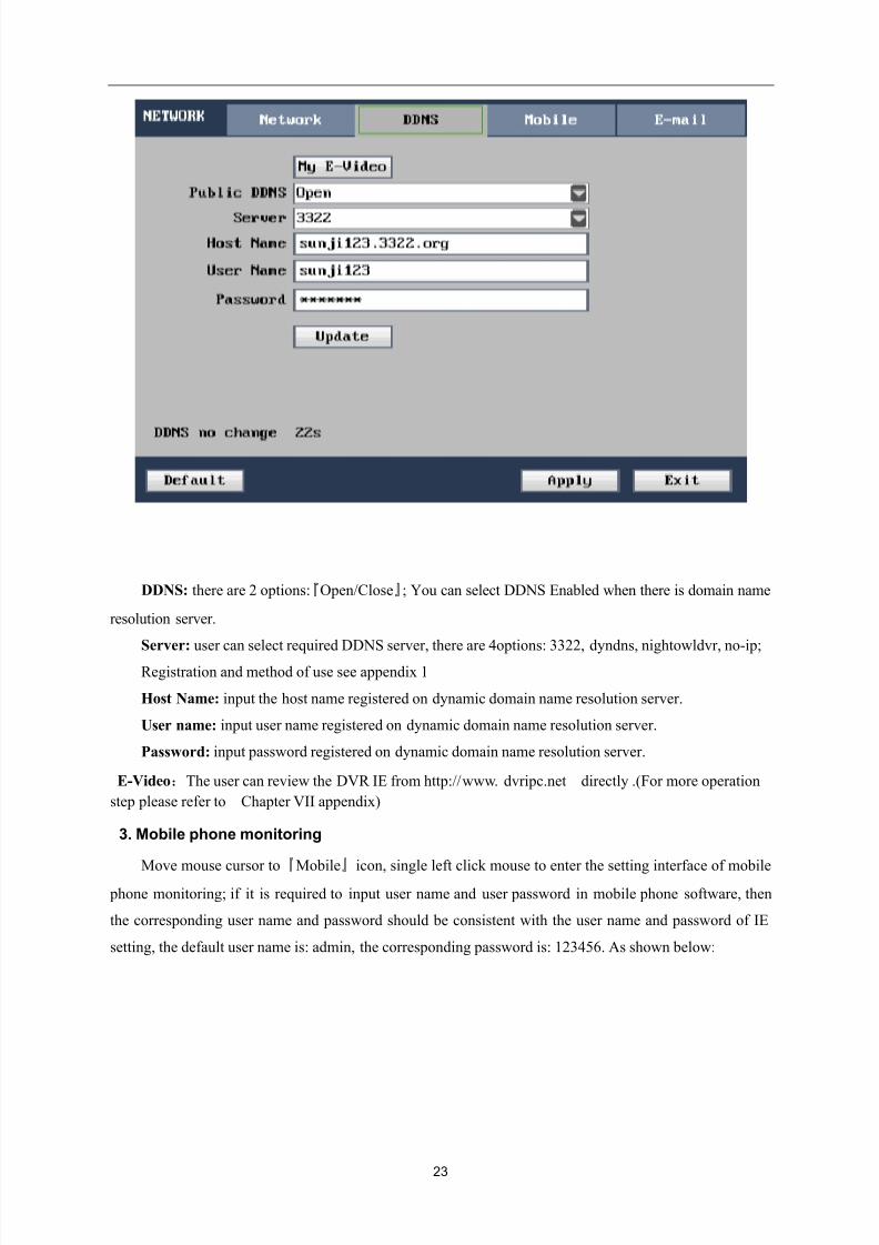
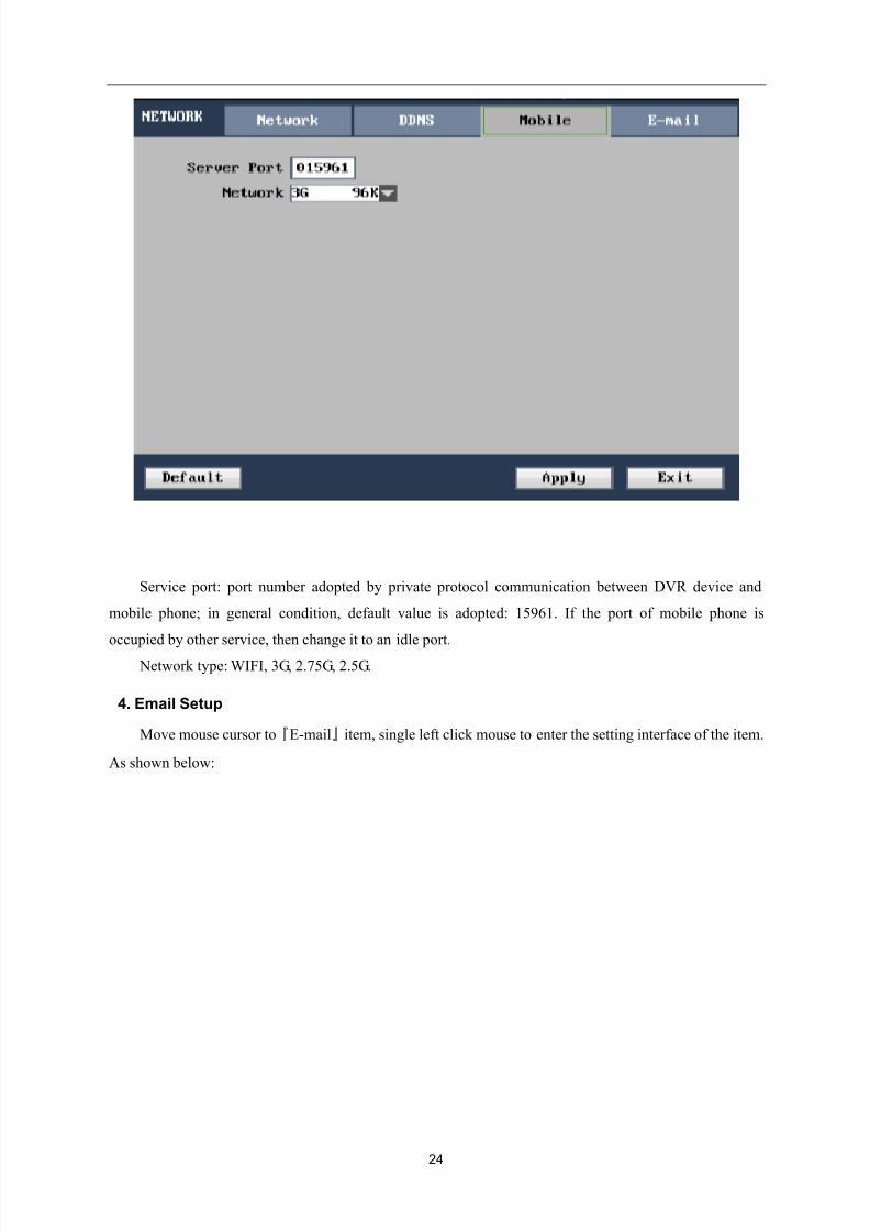
24
Service port: port number adopted by private protocol communication between DVR device and
mobile phone; in general condition, default value is adopted: 15961. If the port of mobile phone is
occupied by other service, then change it to an idle port.
Network type: WIFI, 3G, 2.75G, 2.5G.
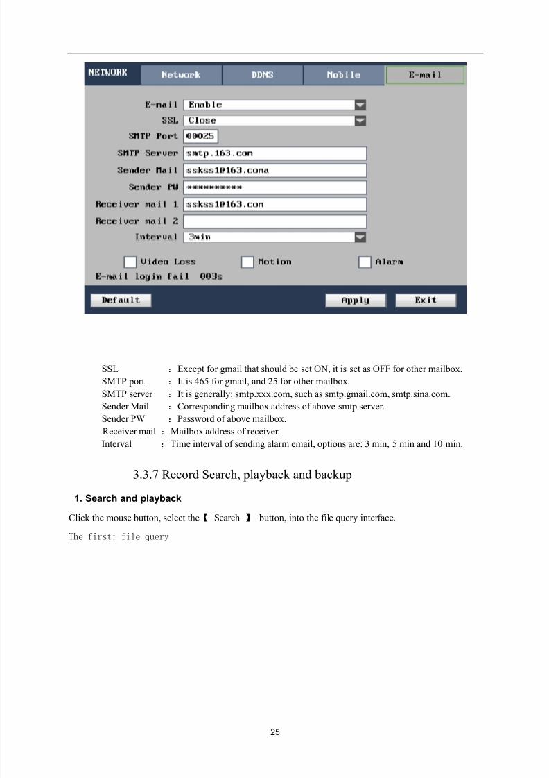
4. Email Setup
Move mouse cursor to『E-mail』item, single left click mouse to enter the setting interface of the item.
As shown below:
8/10/2019 H.264 Standalone DVR User Manual
http://slidepdf.com/reader/full/h264-standalone-dvr-user-manual 25/90
25
SSL :Except for gmail that should be set ON, it is set as OFF for other mailbox.
SMTP port . :It is 465 for gmail, and 25 for other mailbox.
SMTP server :It is generally: smtp.xxx.com, such as smtp.gmail.com, smtp.sina.com.
Sender Mail :Corresponding mailbox address of above smtp server.Sender PW :Password of above mailbox.
Receiver mail :Mailbox address of receiver.
Interval :Time interval of sending alarm email, options are: 3 min, 5 min and 10 min.
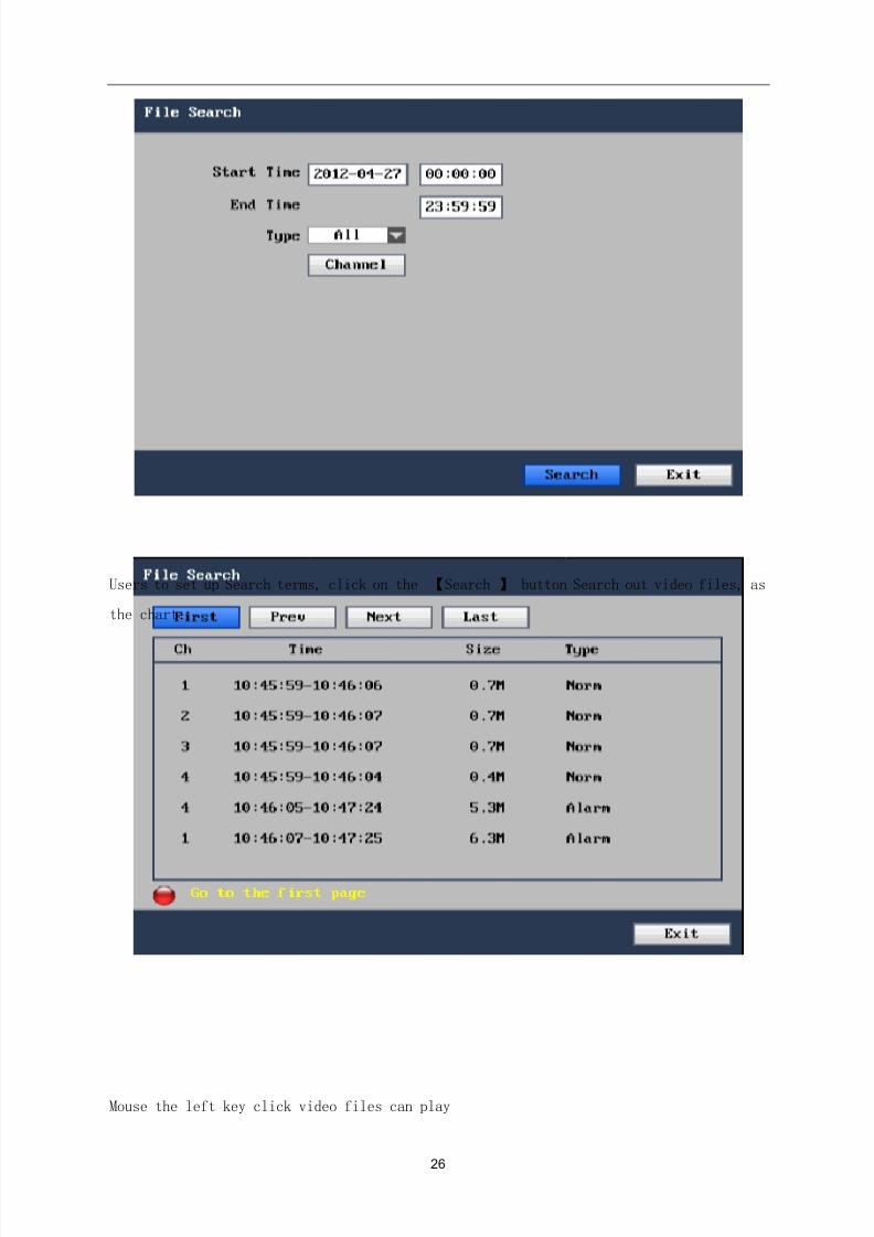
3.3.7 Record Search, playback and backup
1. Search and playback
Click the mouse button, select the【 Search 】 button, into the file query interface.
The first: file query
8/10/2019 H.264 Standalone DVR User Manual
http://slidepdf.com/reader/full/h264-standalone-dvr-user-manual 26/90
26
Users to set up Search terms, click on the 【Search 】 button Search out video files, as
the chart:
Mouse the left key click video files can play
8/10/2019 H.264 Standalone DVR User Manual
http://slidepdf.com/reader/full/h264-standalone-dvr-user-manual 27/90
27
The second: events search (file query operation with the same)
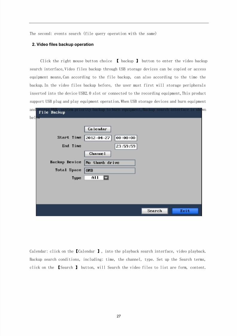
2. Video files backup operation
Click the right mouse button choice 【 backup 】 button to enter the video backup
search interface,Video files backup through USB storage devices can be copied or access
equipment means,Can according to the file backup, can also according to the time the
backup.In the video files backup before, the user must first will storage peripherals
inserted into the device USB2.0 slot or connected to the recording equipment,This product
support USB plug and play equipment operation.When USB storage devices and burn equipment
and access DVR, system priority backup to burn equipment,Backup search interface is shown
below
Calendar: click on the【Calendar 】, into the playback search interface, video playback.
Backup search conditions, including: time, the channel, type. Set up the Search terms,
click on the 【Search 】 button, will Search the video files to list are form, content.
8/10/2019 H.264 Standalone DVR User Manual
http://slidepdf.com/reader/full/h264-standalone-dvr-user-manual 28/90
28
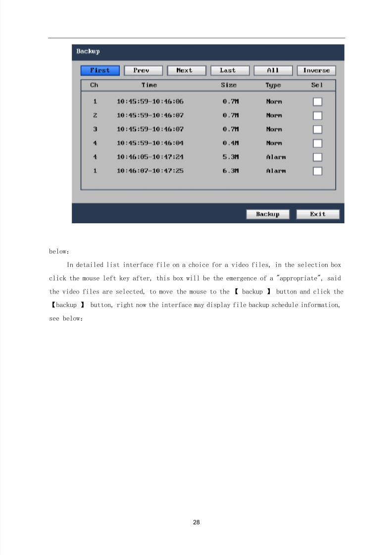
below:
In detailed list interface file on a choice for a video files, in the selection box
click the mouse left key after, this box will be the emergence of a "appropriate", said
the video files are selected, to move the mouse to the【 backup 】 button and click the
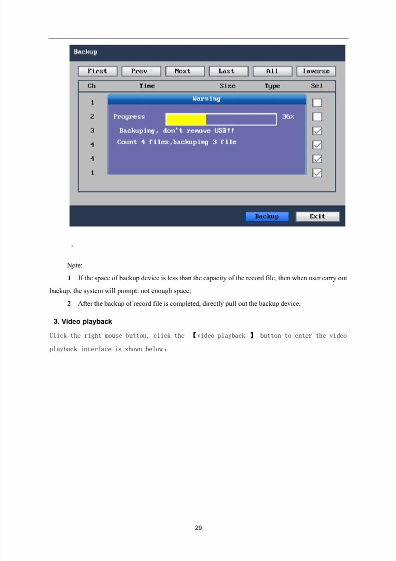
【backup 】 button, right now the interface may display file backup schedule information,
see below:
8/10/2019 H.264 Standalone DVR User Manual
http://slidepdf.com/reader/full/h264-standalone-dvr-user-manual 29/90
29
Note:
1.If the space of backup device is less than the capacity of the record file, then when user carry out
backup, the system will prompt: not enough space;
2.After the backup of record file is completed, directly pull out the backup device.
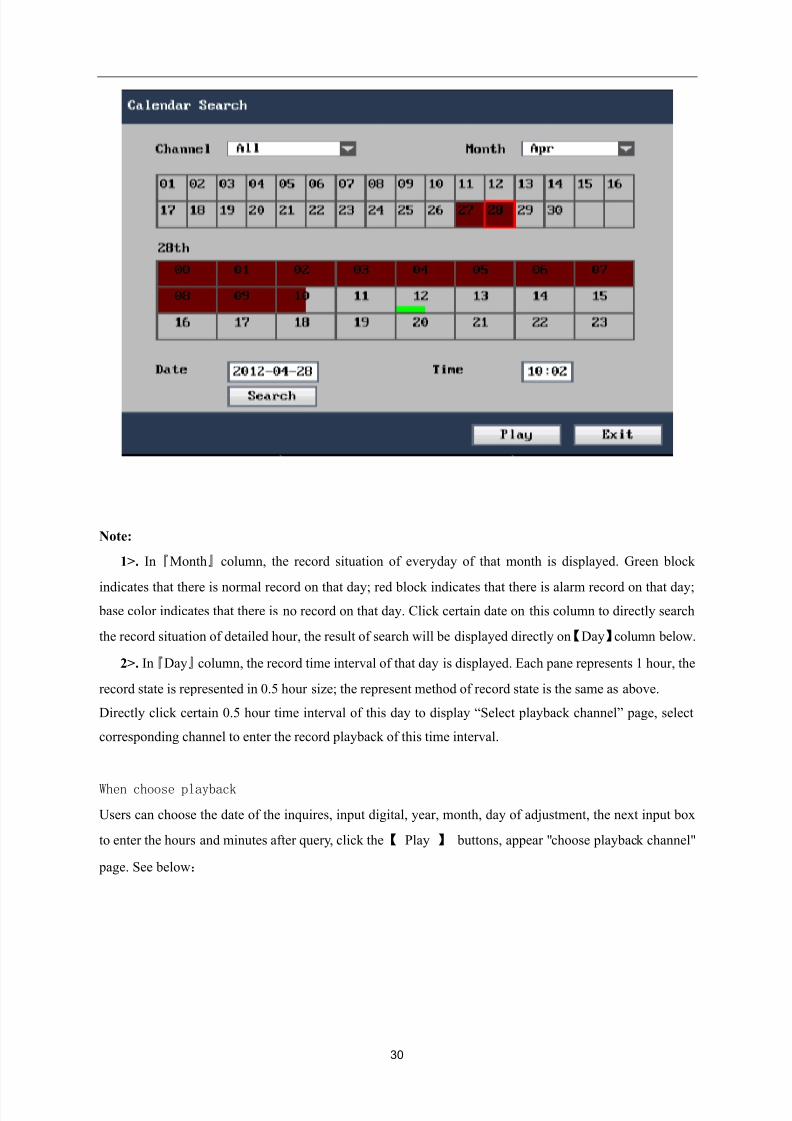
3. Video playback
Click the right mouse button, click the 【video playback 】 button to enter the video
playback interface is shown below:
8/10/2019 H.264 Standalone DVR User Manual
http://slidepdf.com/reader/full/h264-standalone-dvr-user-manual 30/90
30
Note:
1>. In『Month』column, the record situation of everyday of that month is displayed. Green block
indicates that there is normal record on that day; red block indicates that there is alarm record on that day;
base color indicates that there is no record on that day. Click certain date on this column to directly search
the record situation of detailed hour, the result of search will be displayed directly on【Day】column below.
2>. In『Day』column, the record time interval of that day is displayed. Each pane represents 1 hour, the
record state is represented in 0.5 hour size; the represent method of record state is the same as above.
Directly click certain 0.5 hour time interval of this day to display “Select playback channel” page, select
corresponding channel to enter the record playback of this time interval.
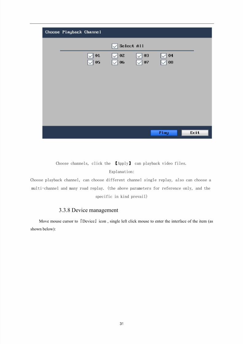
When choose playback
Users can choose the date of the inquires, input digital, year, month, day of adjustment, the next input box
to enter the hours and minutes after query, click the【 Play 】 buttons, appear "choose playback channel"
page. See below:
8/10/2019 H.264 Standalone DVR User Manual
http://slidepdf.com/reader/full/h264-standalone-dvr-user-manual 31/90
31
Choose channels, click the 【Apply】 can playback video files.
Explanation:
Choose playback channel, can choose different channel single replay, also can choose a
multi-channel and many road replay. (the above parameters for reference only, and the
specific in kind prevail)
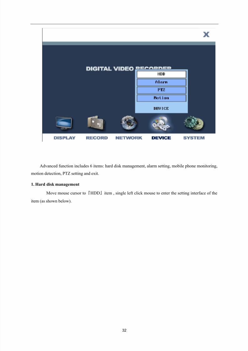
3.3.8 Device management
Move mouse cursor to『Device』icon , single left click mouse to enter the interface of the item (as
shown below):
8/10/2019 H.264 Standalone DVR User Manual
http://slidepdf.com/reader/full/h264-standalone-dvr-user-manual 32/90
32
Advanced function includes 6 items: hard disk management, alarm setting, mobile phone monitoring,
motion detection, PTZ setting and exit.
1. Hard disk management
Move mouse cursor to『HDD』item , single left click mouse to enter the setting interface of the
item (as shown below).
8/10/2019 H.264 Standalone DVR User Manual
http://slidepdf.com/reader/full/h264-standalone-dvr-user-manual 33/90
33
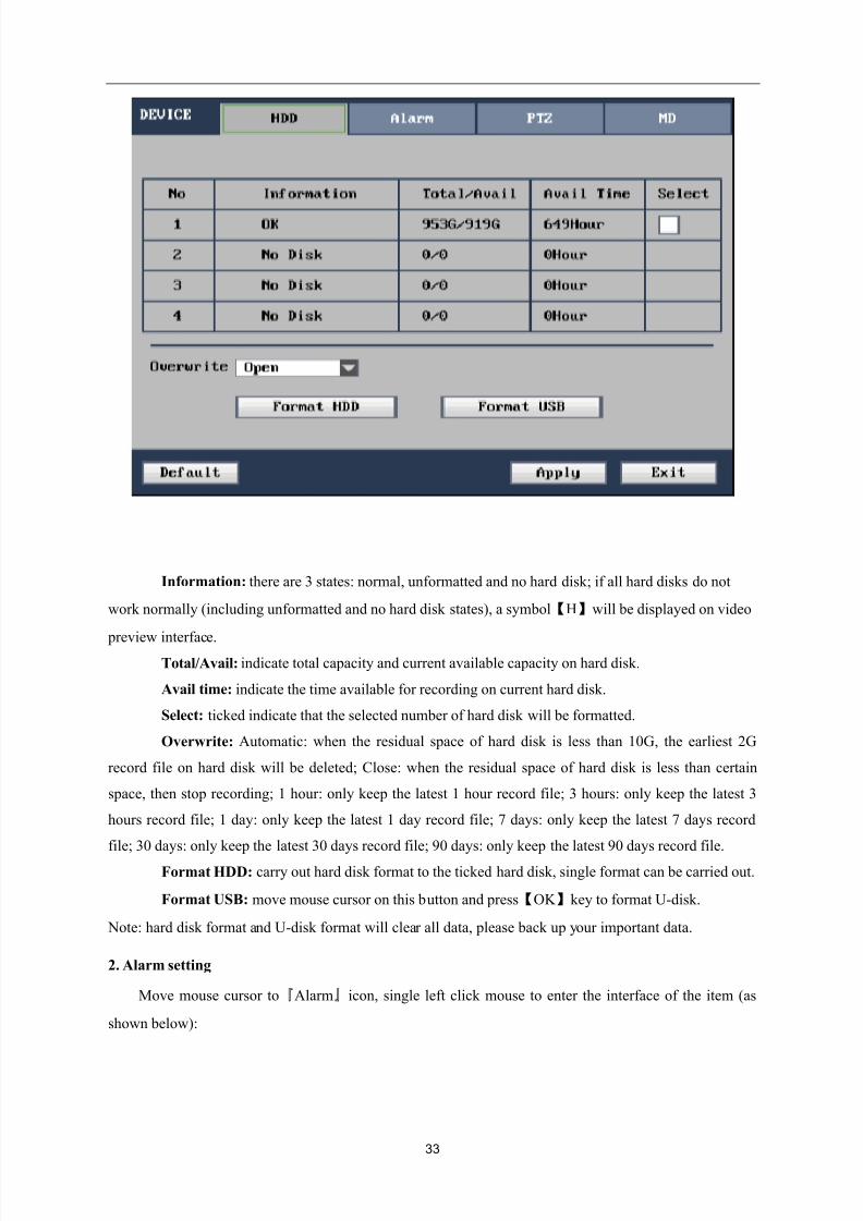
Information: there are 3 states: normal, unformatted and no hard disk; if all hard disks do not
work normally (including unformatted and no hard disk states), a symbol【H】will be displayed on video
preview interface.Total/Avail: indicate total capacity and current available capacity on hard disk.
Avail time: indicate the time available for recording on current hard disk.
Select: ticked indicate that the selected number of hard disk will be formatted.
Overwrite: Automatic: when the residual space of hard disk is less than 10G, the earliest 2G
record file on hard disk will be deleted; Close: when the residual space of hard disk is less than certain
space, then stop recording; 1 hour: only keep the latest 1 hour record file; 3 hours: only keep the latest 3
hours record file; 1 day: only keep the latest 1 day record file; 7 days: only keep the latest 7 days record
file; 30 days: only keep the latest 30 days record file; 90 days: only keep the latest 90 days record file.
Format HDD: carry out hard disk format to the ticked hard disk, single format can be carried out.
Format USB: move mouse cursor on this button and press【OK 】key to format U-disk.
Note: hard disk format and U-disk format will clear all data, please back up your important data.
2. Alarm setting
Move mouse cursor to『Alarm』icon, single left click mouse to enter the interface of the item (as
shown below):
8/10/2019 H.264 Standalone DVR User Manual
http://slidepdf.com/reader/full/h264-standalone-dvr-user-manual 34/90
34
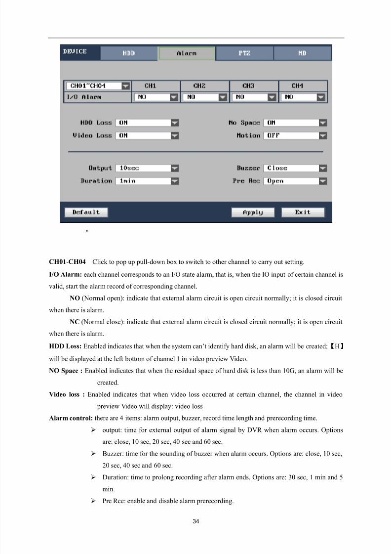
CH01-CH04:Click to pop up pull-down box to switch to other channel to carry out setting.
I/O Alarm: each channel corresponds to an I/O state alarm, that is, when the IO input of certain channel is
valid, start the alarm record of corresponding channel.
NO (Normal open): indicate that external alarm circuit is open circuit normally; it is closed circuit
when there is alarm.
NC (Normal close): indicate that external alarm circuit is closed circuit normally; it is open circuit
when there is alarm.
HDD Loss: Enabled indicates that when the system can’t identify hard disk, an alarm will be created;【H】
will be displayed at the left bottom of channel 1 in video preview Video.
NO Space : Enabled indicates that when the residual space of hard disk is less than 10G, an alarm will be
created.
Video loss : Enabled indicates that when video loss occurred at certain channel, the channel in video
preview Video will display: video loss
Alarm control: there are 4 items: alarm output, buzzer, record time length and prerecording time.
output: time for external output of alarm signal by DVR when alarm occurs. Options
are: close, 10 sec, 20 sec, 40 sec and 60 sec.
Buzzer: time for the sounding of buzzer when alarm occurs. Options are: close, 10 sec,
20 sec, 40 sec and 60 sec.
Duration: time to prolong recording after alarm ends. Options are: 30 sec, 1 min and 5
min.
Pre Rce: enable and disable alarm prerecording.
8/10/2019 H.264 Standalone DVR User Manual
http://slidepdf.com/reader/full/h264-standalone-dvr-user-manual 35/90
35
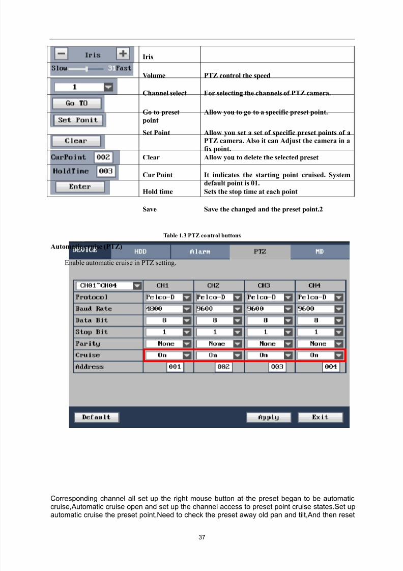
3. PTZ setting
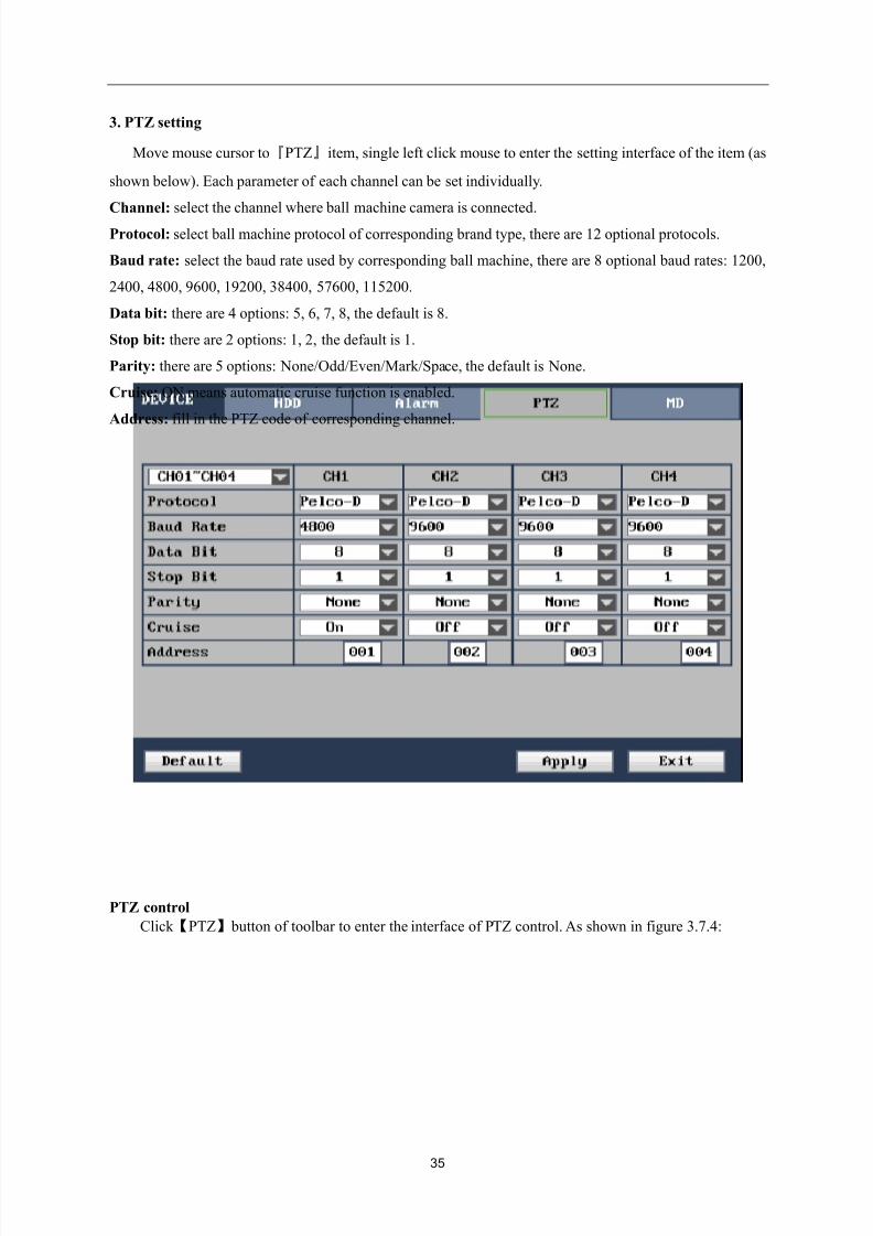
Move mouse cursor to『PTZ』item, single left click mouse to enter the setting interface of the item (as
shown below). Each parameter of each channel can be set individually.
Channel: select the channel where ball machine camera is connected.
Protocol: select ball machine protocol of corresponding brand type, there are 12 optional protocols.
Baud rate: select the baud rate used by corresponding ball machine, there are 8 optional baud rates: 1200,
2400, 4800, 9600, 19200, 38400, 57600, 115200.
Data bit: there are 4 options: 5, 6, 7, 8, the default is 8.
Stop bit: there are 2 options: 1, 2, the default is 1.
Parity: there are 5 options: None/Odd/Even/Mark/Space, the default is None.
Cruise: ON means automatic cruise function is enabled.
Address: fill in the PTZ code of corresponding channel.
PTZ control
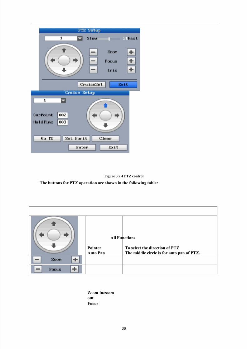
Click 【PTZ】 button of toolbar to enter the interface of PTZ control. As shown in figure 3.7.4:
8/10/2019 H.264 Standalone DVR User Manual
http://slidepdf.com/reader/full/h264-standalone-dvr-user-manual 36/90
36
Figure 3.7.4 PTZ control
The buttons for PTZ operation are shown in the following table:
All Functions
Pointer
Auto Pan
To select the direction of PTZ
The middle circle is for auto pan of PTZ.
Zoom in/zoom
out
Focus
8/10/2019 H.264 Standalone DVR User Manual
http://slidepdf.com/reader/full/h264-standalone-dvr-user-manual 37/90
37
Iris
Volume PTZ control the speed
Channel select For selecting the channels of PTZ camera.
Go to preset
point
Allow you to go to a specific preset point.
Set Point Allow you set a set of specific preset points of a
PTZ camera. Also it can Adjust the camera in a
fix point.
Clear Allow you to delete the selected preset
Cur Point It indicates the starting point cruised. System
default point is 01.
Hold time Sets the stop time at each point
Save Save the changed and the preset point.2
Table 1.3 PTZ control buttons
Automatic cruise (PTZ)
Enable automatic cruise in PTZ setting.
Corresponding channel all set up the right mouse button at the preset began to be automaticcruise,Automatic cruise open and set up the channel access to preset point cruise states.Set upautomatic cruise the preset point,Need to check the preset away old pan and tilt,And then reset
8/10/2019 H.264 Standalone DVR User Manual
http://slidepdf.com/reader/full/h264-standalone-dvr-user-manual 38/90
38
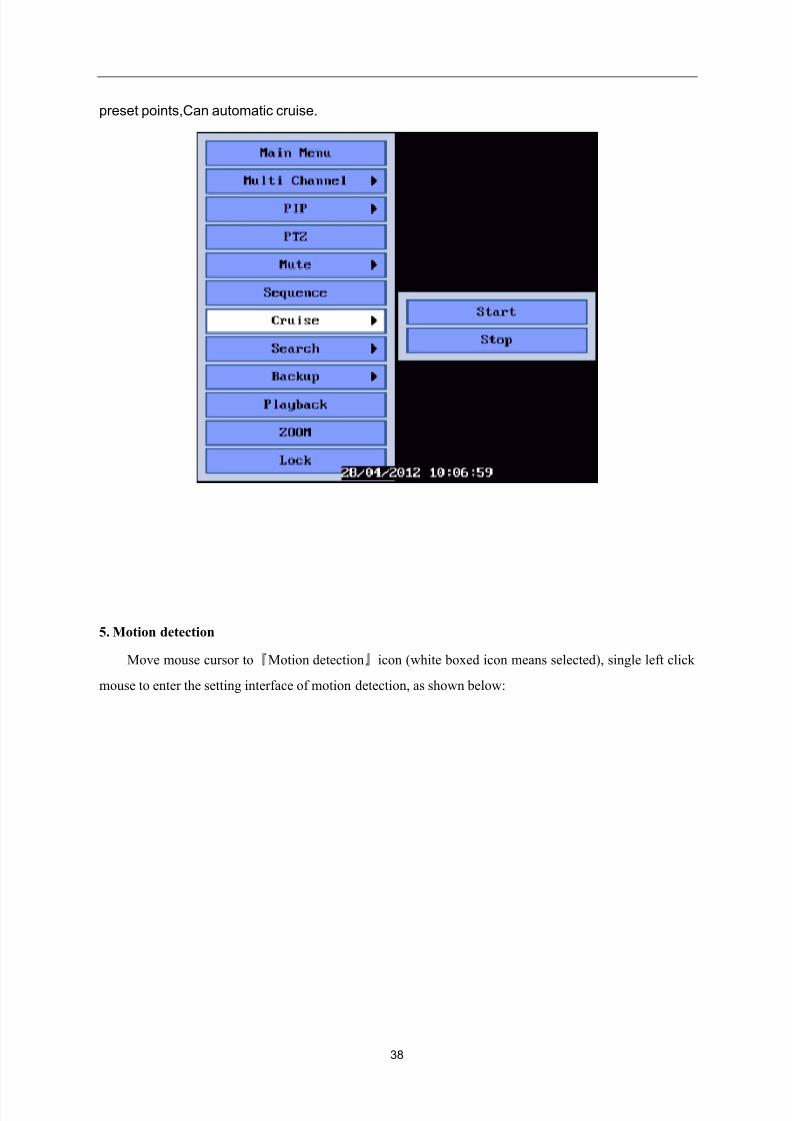
preset points,Can automatic cruise.
5. Motion detection
Move mouse cursor to『Motion detection』icon (white boxed icon means selected), single left click
mouse to enter the setting interface of motion detection, as shown below:
8/10/2019 H.264 Standalone DVR User Manual
http://slidepdf.com/reader/full/h264-standalone-dvr-user-manual 39/90
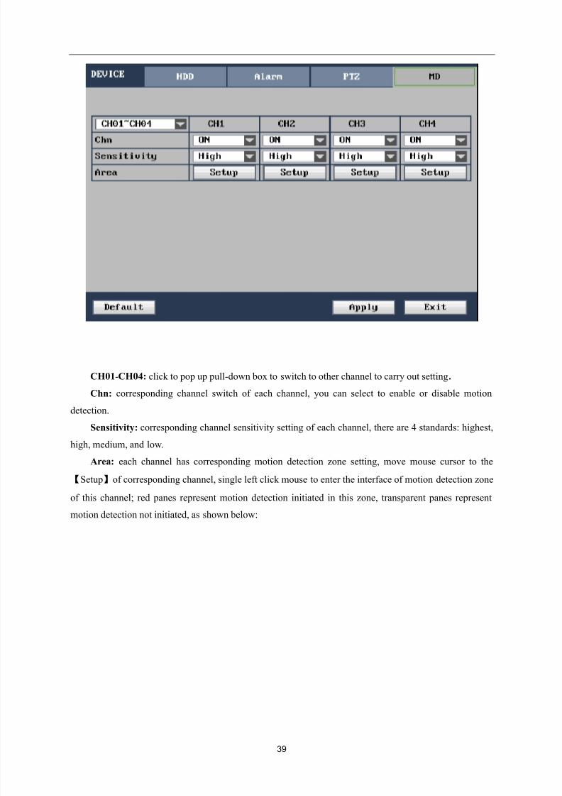
39
CH01-CH04: click to pop up pull-down box to switch to other channel to carry out setting.
Chn: corresponding channel switch of each channel, you can select to enable or disable motion
detection.
Sensitivity: corresponding channel sensitivity setting of each channel, there are 4 standards: highest,
high, medium, and low.
Area: each channel has corresponding motion detection zone setting, move mouse cursor to the
【Setup】of corresponding channel, single left click mouse to enter the interface of motion detection zone
of this channel; red panes represent motion detection initiated in this zone, transparent panes represent
motion detection not initiated, as shown below:
8/10/2019 H.264 Standalone DVR User Manual
http://slidepdf.com/reader/full/h264-standalone-dvr-user-manual 40/90
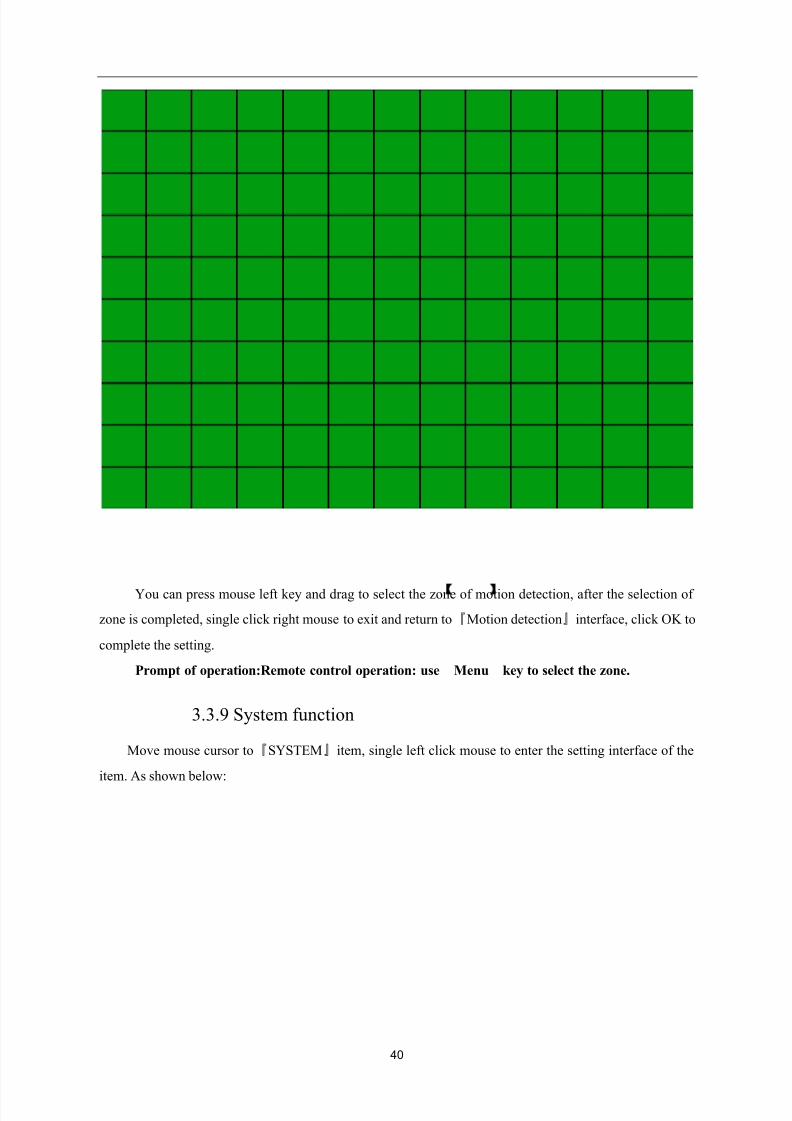
40
You can press mouse left key and drag to select the zone of motion detection, after the selection of
zone is completed, single click right mouse to exit and return to『Motion detection』interface, click OK to
complete the setting.
Prompt of operation:Remote control operation: use Menu】key to select the zone.
3.3.9 System function
Move mouse cursor to『SYSTEM』item, single left click mouse to enter the setting interface of the
item. As shown below:
8/10/2019 H.264 Standalone DVR User Manual
http://slidepdf.com/reader/full/h264-standalone-dvr-user-manual 41/90
41
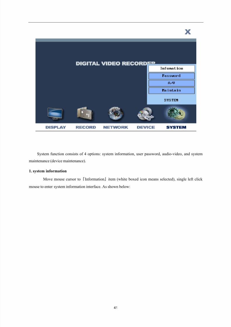
System function consists of 4 options: system information, user password, audio-video, and system
maintenance (device maintenance).
1. system information
Move mouse cursor to『Information』item (white boxed icon means selected), single left click
mouse to enter system information interface. As shown below:
8/10/2019 H.264 Standalone DVR User Manual
http://slidepdf.com/reader/full/h264-standalone-dvr-user-manual 42/90
42
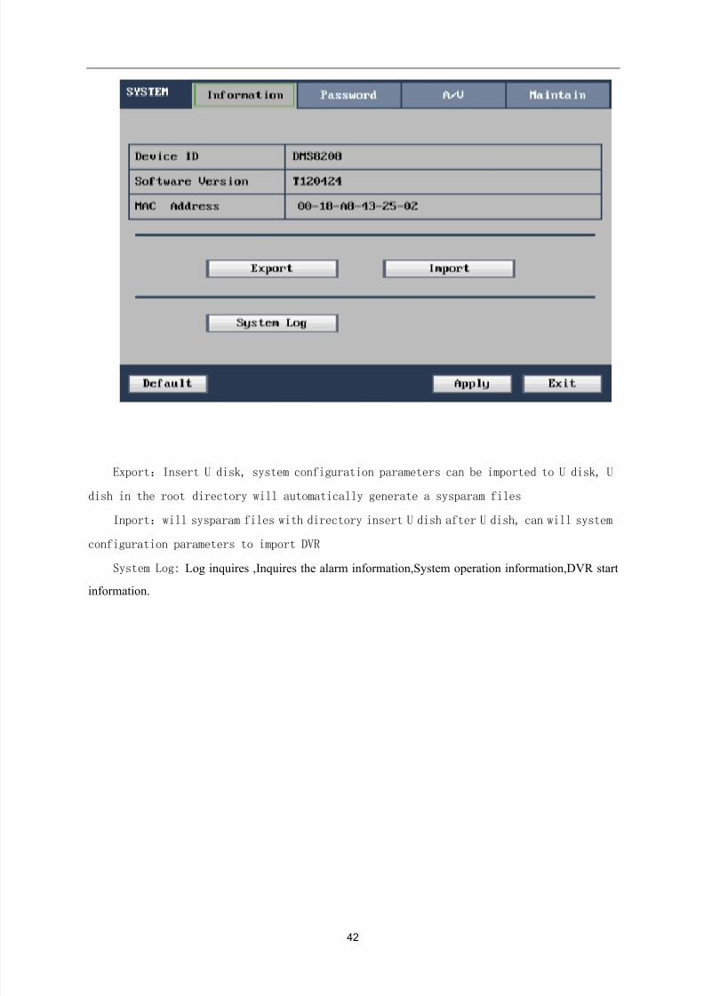
Export:Insert U disk, system configuration parameters can be imported to U disk, U
dish in the root directory will automatically generate a sysparam files
Inport:will sysparam files with directory insert U dish after U dish, can will systemconfiguration parameters to import DVR
System Log: Log inquires ,Inquires the alarm information,System operation information,DVR start
information.
8/10/2019 H.264 Standalone DVR User Manual
http://slidepdf.com/reader/full/h264-standalone-dvr-user-manual 43/90
43
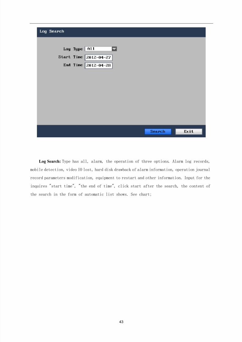
Log Search: Type has all, alarm, the operation of three options. Alarm log records,
mobile detection, video IO lost, hard disk drawback of alarm information, operation journal
record parameters modification, equipment to restart and other information. Input for the
inquires "start time", "the end of time", click start after the search, the content of
the search in the form of automatic list shows. See chart;
8/10/2019 H.264 Standalone DVR User Manual
http://slidepdf.com/reader/full/h264-standalone-dvr-user-manual 44/90
8/10/2019 H.264 Standalone DVR User Manual
http://slidepdf.com/reader/full/h264-standalone-dvr-user-manual 45/90
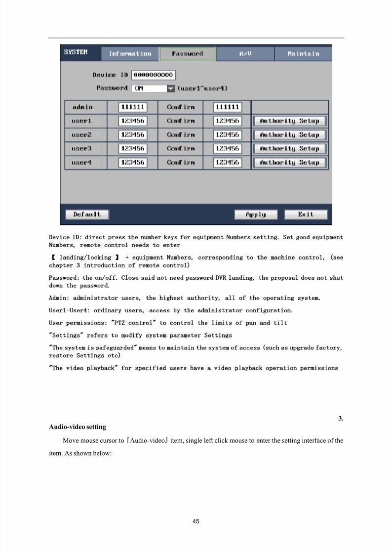
45
Device ID: direct press the number keys for equipment Numbers setting. Set good equipment
Numbers, remote control needs to enter
landing/locking
】
+ equipment Numbers, corresponding to the machine control, (see
chapter 3 introduction of remote control)
Password: the on/off. Close said not need password DVR landing, the proposal does not shut
down the password.
Admin: administrator users, the highest authority, all of the operating system.
User1-User4: ordinary users, access by the administrator configuration.
User permissions: PTZ control to control the limits of pan and tilt
Settings refers to modify system parameter Settings
The system is safeguarded means to maintain the system of access (such as upgrade factory,
restore Settings etc)
The video playback for specified users have a video playback operation permissions3.
Audio-video setting
Move mouse cursor to『Audio-video』item, single left click mouse to enter the setting interface of the
item. As shown below:
8/10/2019 H.264 Standalone DVR User Manual
http://slidepdf.com/reader/full/h264-standalone-dvr-user-manual 46/90
46
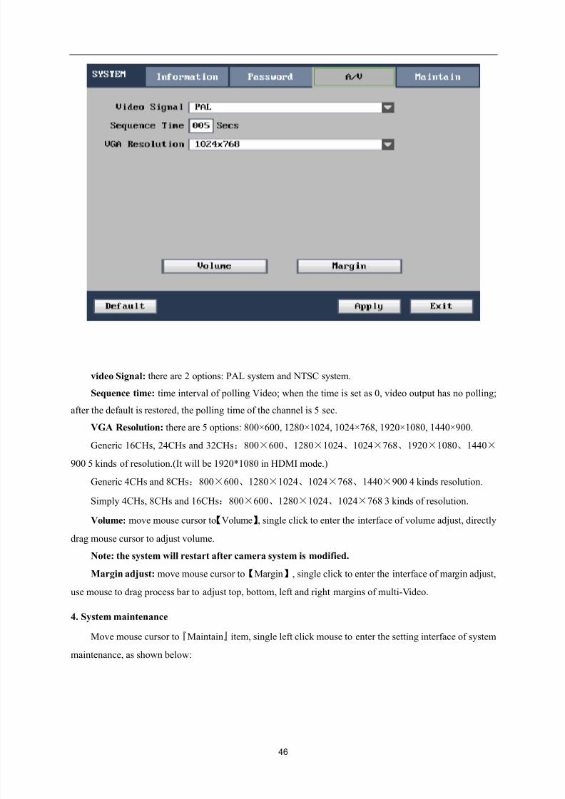
video Signal: there are 2 options: PAL system and NTSC system.
Sequence time: time interval of polling Video; when the time is set as 0, video output has no polling;
after the default is restored, the polling time of the channel is 5 sec.
VGA Resolution: there are 5 options: 800×600, 1280×1024, 1024×768, 1920×1080, 1440×900.
Generic 16CHs, 24CHs and 32CHs:800×600、1280×1024、1024×768、1920×1080、1440×
900 5 kinds of resolution.(It will be 1920*1080 in HDMI mode.)
Generic 4CHs and 8CHs:800×600、1280×1024、1024×768、1440×900 4 kinds resolution.
Simply 4CHs, 8CHs and 16CHs:800×600、1280×1024、1024×768 3 kinds of resolution.
Volume: move mouse cursor to【Volume】, single click to enter the interface of volume adjust, directly
drag mouse cursor to adjust volume.
Note: the system will restart after camera system is modified.Margin adjust: move mouse cursor to【Margin】, single click to enter the interface of margin adjust,
use mouse to drag process bar to adjust top, bottom, left and right margins of multi-Video.
4. System maintenance
Move mouse cursor to『Maintain』item, single left click mouse to enter the setting interface of system
maintenance, as shown below:
8/10/2019 H.264 Standalone DVR User Manual
http://slidepdf.com/reader/full/h264-standalone-dvr-user-manual 47/90
47
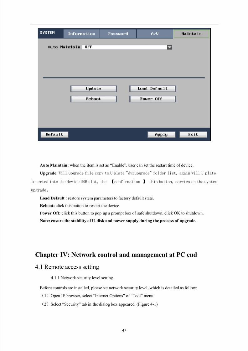
Auto Maintain: when the item is set as “Enable”, user can set the restart time of device.
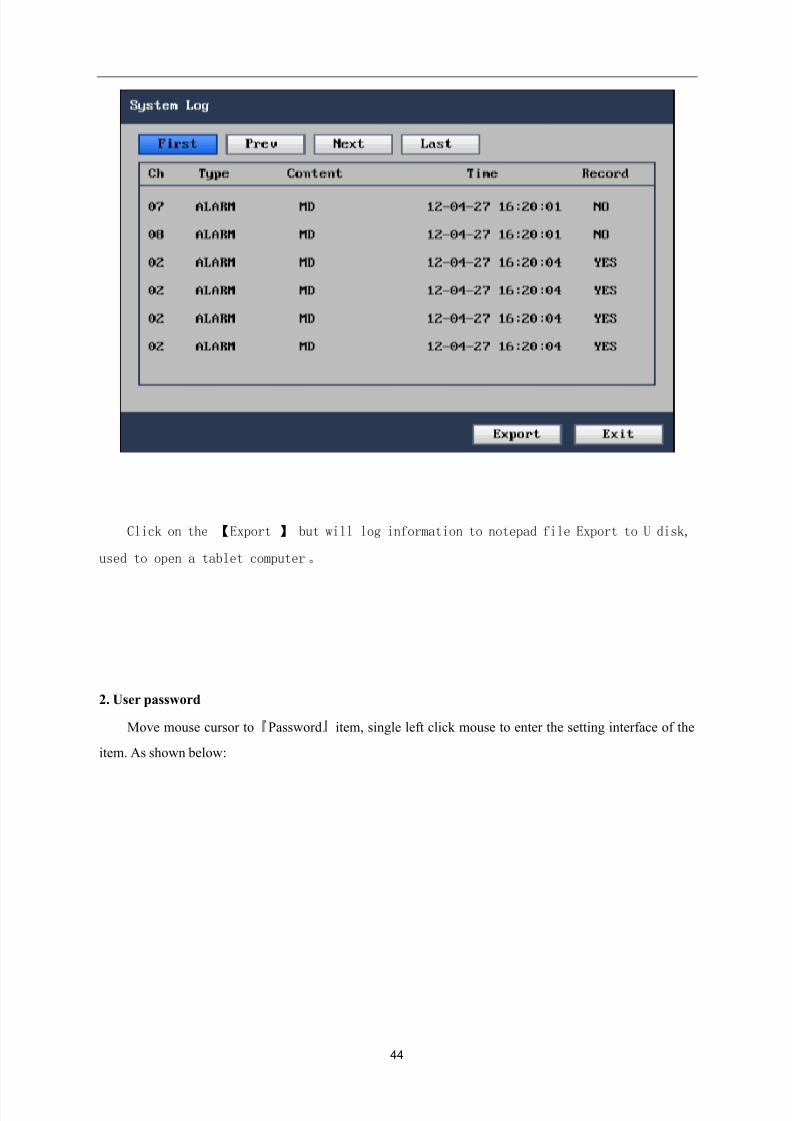
Upgrade: Will upgrade file copy to U plate "dvrupgrade" folder list, again will U plate
inserted into the device USB slot, the 【confirmation 】 this button, carries on the system
upgrade。
Load Default : restore system parameters to factory default state.
Reboot: click this button to restart the device.
Power Off: click this button to pop up a prompt box of safe shutdown, click OK to shutdown.
Note: ensure the stability of U-disk and power supply during the process of upgrade.
Chapter IV: Network control and management at PC end
4.1 Remote access setting
4.1.1 Network security level setting
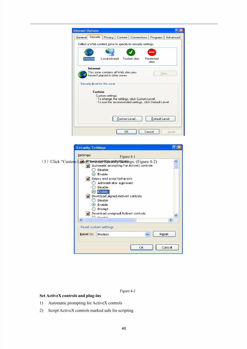
Before controls are installed, please set network security level, which is detailed as follow:
(1)Open IE browser, select “Internet Options” of “Tool” menu.
(2)Select “Security” tab in the dialog box appeared. (Figure 4-1)
8/10/2019 H.264 Standalone DVR User Manual
http://slidepdf.com/reader/full/h264-standalone-dvr-user-manual 48/90
48
Figure 4-1
(3)Click “Custom Level” to enter Security Settings. (Figure 4-2)
Figure 4-2
Set ActiveX controls and plug-ins
1) Automatic prompting for ActiveX controls
2) Script ActiveX controls marked safe for scripting
8/10/2019 H.264 Standalone DVR User Manual
http://slidepdf.com/reader/full/h264-standalone-dvr-user-manual 49/90
49
3) Initialize and script ActiveX controls not marked as safe
4) Binary and script behaviors
5) Download unsigned ActiveX controls
6) Download signed ActiveX controls
7) Run ActiveX controls and plug-ins
Set above items as “Enable”, this is very important.
Prompt: before controls are installed, please close fire wall and virus-killing software.
4.1.2 Connection setting
The remote access of hard disk video recorder is carried out through network; when LAN connection
is used, the IP addresses of client end computer and hard disk video recorder should be within the
same network segment; when WAN connection is used, connection can be realized through IP address
or dynamic domain name, ensure that both sides can access the public network. The connection
setting method of LAN is mainly introduced as follow.
Step 1: right click “Network Neighborhood”, click “Property” in pop up menu, so as to open
“Network Connection”.
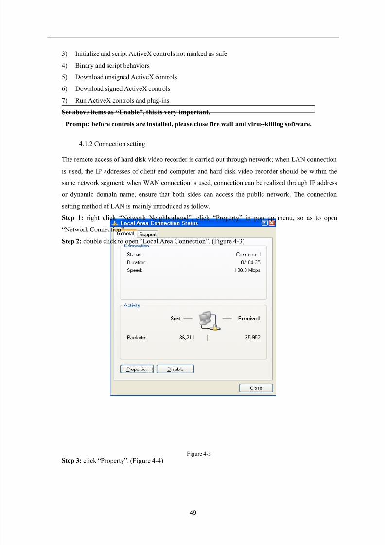
Step 2: double click to open “Local Area Connection”. (Figure 4-3)
Figure 4-3
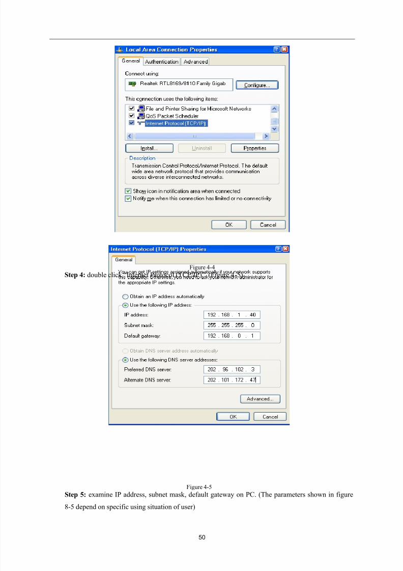
Step 3: click “Property”. (Figure 4-4)
8/10/2019 H.264 Standalone DVR User Manual
http://slidepdf.com/reader/full/h264-standalone-dvr-user-manual 50/90
50
Figure 4-4
Step 4: double click “Internet Protocol (TCP/IP)”. (Figure 4-5)
Figure 4-5
Step 5: examine IP address, subnet mask, default gateway on PC. (The parameters shown in figure
8-5 depend on specific using situation of user)
8/10/2019 H.264 Standalone DVR User Manual
http://slidepdf.com/reader/full/h264-standalone-dvr-user-manual 51/90
51
Step 6: set corresponding IP address, subnet mask, default gateway of hard disk video recorder (see
section 3.3.5 network setting). Therein the subnet mask and default gateway of hard disk video
recorder should be the same as PC, ensure that their IP addresses must be in the same network
segment, but the IP address can’t be the same as used IP address, otherwise IP address conflict will be
resulted. Take above figure for example, the IP address should be: 192.168.0.X, therein X can’t be 40
or 1 (including other used IP address), and can’t exceed 255, the subnet mask is 255.255.255.0, the
gateway is 192.168.0.1.
4.2 Functional characteristics
Network operation is used to install software through IE browser of the operation system, which is
simple and easy; DVR supports C/S, B/S structure, LAN and WAN access, and supports IP and domain
name access at the same time.
Support user to modify service port, and support PPPOE, DHCP functions at the same time.
4.3 Constraint condition
In order to ensure PC to stably access this DVR product, it is recommended to use Windows XP,
Windows Vista operation system; and IE6.0, IE7.0 browsers are recommended.
4.4 User login
Input current IP of the device in IE, if the WEB port number is set as (80), then directly input IP
address in IE address field; if the WEB port is modified as a port other than 80, then the port number
should be added after IP address; for example: the IP of device is 192.168.1.118, set the port as 8088, then
input: http://192.168.1.118:8088 to access the device.
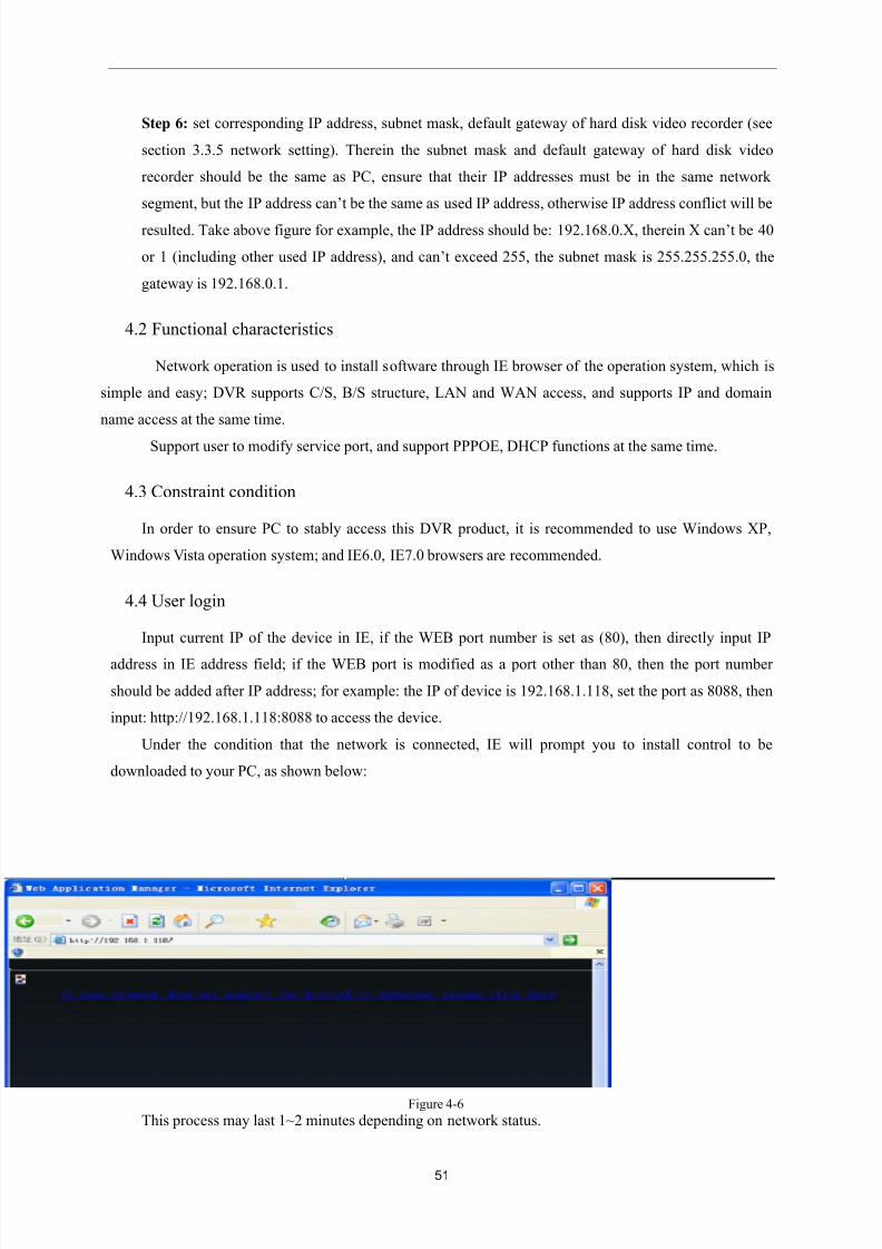
Under the condition that the network is connected, IE will prompt you to install control to be
downloaded to your PC, as shown below:
Figure 4-6
This process may last 1~2 minutes depending on network status.
8/10/2019 H.264 Standalone DVR User Manual
http://slidepdf.com/reader/full/h264-standalone-dvr-user-manual 52/90
52
The download may not be successful because of PC configuration problem, please click:
“ ”.
“If your browser does not support the ActivX to download, please click here” means “If your browser
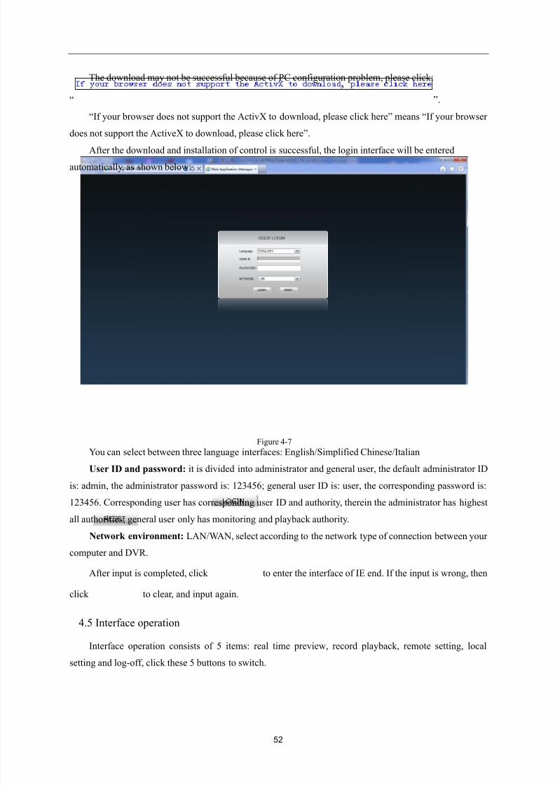
does not support the ActiveX to download, please click here”. After the download and installation of control is successful, the login interface will be entered
automatically, as shown below:
Figure 4-7
You can select between three language interfaces: English/Simplified Chinese/Italian
User ID and password: it is divided into administrator and general user, the default administrator ID
is: admin, the administrator password is: 123456; general user ID is: user, the corresponding password is:
123456. Corresponding user has corresponding user ID and authority, therein the administrator has highest
all authorities; general user only has monitoring and playback authority.
Network environment: LAN/WAN, select according to the network type of connection between your
computer and DVR.
After input is completed, click to enter the interface of IE end. If the input is wrong, then
click to clear, and input again.
4.5 Interface operation
Interface operation consists of 5 items: real time preview, record playback, remote setting, local
setting and log-off, click these 5 buttons to switch.
8/10/2019 H.264 Standalone DVR User Manual
http://slidepdf.com/reader/full/h264-standalone-dvr-user-manual 53/90
53
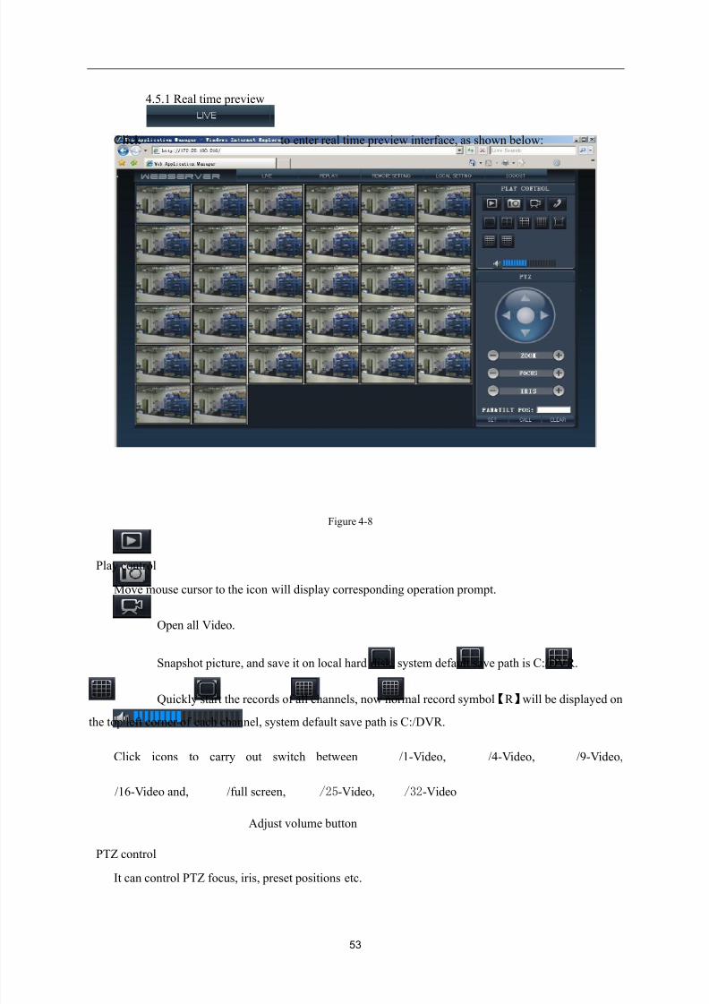
4.5.1 Real time preview
Click to enter real time preview interface, as shown below:
Figure 4-8
Play control
Move mouse cursor to the icon will display corresponding operation prompt.
Open all Video.
Snapshot picture, and save it on local hard disk, system default save path is C:/DVR.
Quickly start the records of all channels, now normal record symbol【R 】will be displayed onthe top left corner of each channel, system default save path is C:/DVR.
Click icons to carry out switch between /1-Video, /4-Video, /9-Video,
/16-Video and, /full screen, /25-Video, /32-Video
Adjust volume button
PTZ control
It can control PTZ focus, iris, preset positions etc.
8/10/2019 H.264 Standalone DVR User Manual
http://slidepdf.com/reader/full/h264-standalone-dvr-user-manual 54/90
54
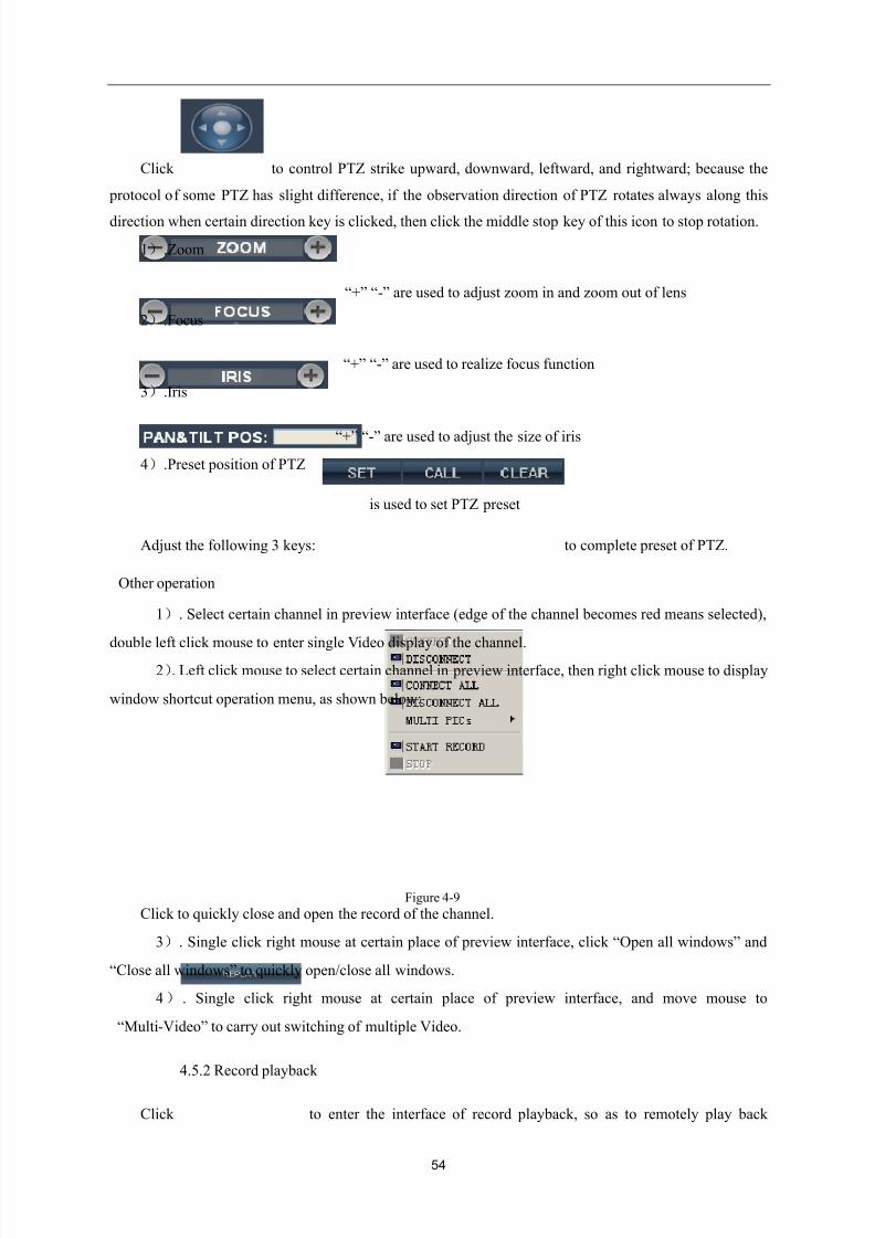
Click to control PTZ strike upward, downward, leftward, and rightward; because the
protocol of some PTZ has slight difference, if the observation direction of PTZ rotates always along this
direction when certain direction key is clicked, then click the middle stop key of this icon to stop rotation.
1).Zoom
“+” “-” are used to adjust zoom in and zoom out of lens
2).Focus
“+” “-” are used to realize focus function
3).Iris
“+” “-” are used to adjust the size of iris
4).Preset position of PTZ
is used to set PTZ preset
Adjust the following 3 keys: to complete preset of PTZ.
Other operation
1). Select certain channel in preview interface (edge of the channel becomes red means selected),
double left click mouse to enter single Video display of the channel.
2). Left click mouse to select certain channel in preview interface, then right click mouse to display
window shortcut operation menu, as shown below:
Figure 4-9
Click to quickly close and open the record of the channel.
3). Single click right mouse at certain place of preview interface, click “Open all windows” and
“Close all windows” to quickly open/close all windows.
4 ) . Single click right mouse at certain place of preview interface, and move mouse to
“Multi-Video” to carry out switching of multiple Video.
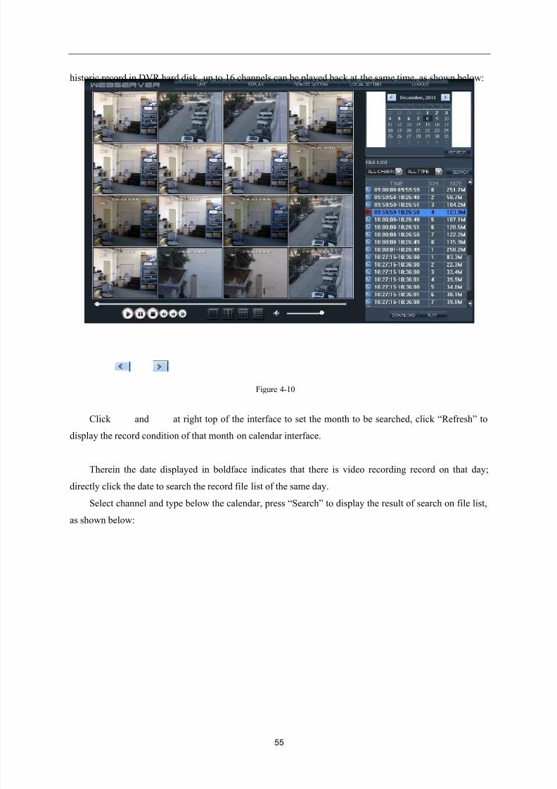
4.5.2 Record playback
Click to enter the interface of record playback, so as to remotely play back
8/10/2019 H.264 Standalone DVR User Manual
http://slidepdf.com/reader/full/h264-standalone-dvr-user-manual 55/90
55
historic record in DVR hard disk, up to 16 channels can be played back at the same time, as shown below:
Figure 4-10
Click and at right top of the interface to set the month to be searched, click “Refresh” to
display the record condition of that month on calendar interface.
Therein the date displayed in boldface indicates that there is video recording record on that day;
directly click the date to search the record file list of the same day.
Select channel and type below the calendar, press “Search” to display the result of search on file list,
as shown below:
8/10/2019 H.264 Standalone DVR User Manual
http://slidepdf.com/reader/full/h264-standalone-dvr-user-manual 56/90
56
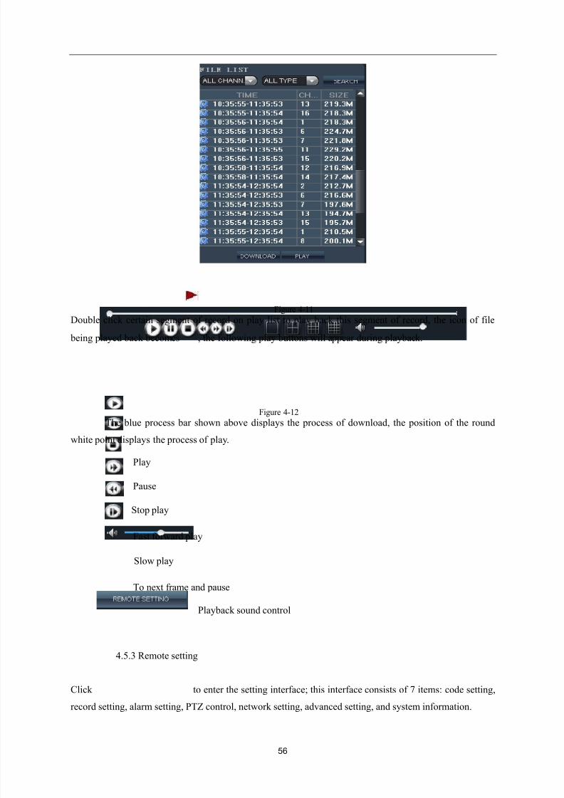
Figure 4-11
Double click certain segment of record on play list to play back this segment of record, the icon of file
being played back becomes , the following play buttons will appear during playback.
Figure 4-12
The blue process bar shown above displays the process of download, the position of the round
white point displays the process of play.
Play
Pause
Stop play
Fast forward play
Slow play
To next frame and pause
Playback sound control
4.5.3 Remote setting
Click to enter the setting interface; this interface consists of 7 items: code setting,
record setting, alarm setting, PTZ control, network setting, advanced setting, and system information.
8/10/2019 H.264 Standalone DVR User Manual
http://slidepdf.com/reader/full/h264-standalone-dvr-user-manual 57/90
57
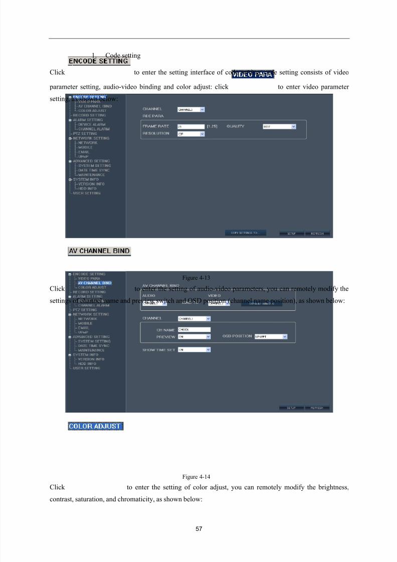
1. Code setting
Click to enter the setting interface of code setting; code setting consists of video
parameter setting, audio-video binding and color adjust: click to enter video parameter
setting, as shown below:
Figure 4-13
Click to enter the setting of audio-video parameters, you can remotely modify the
settings of channel name and preview switch and OSD position (channel name position), as shown below:
Figure 4-14
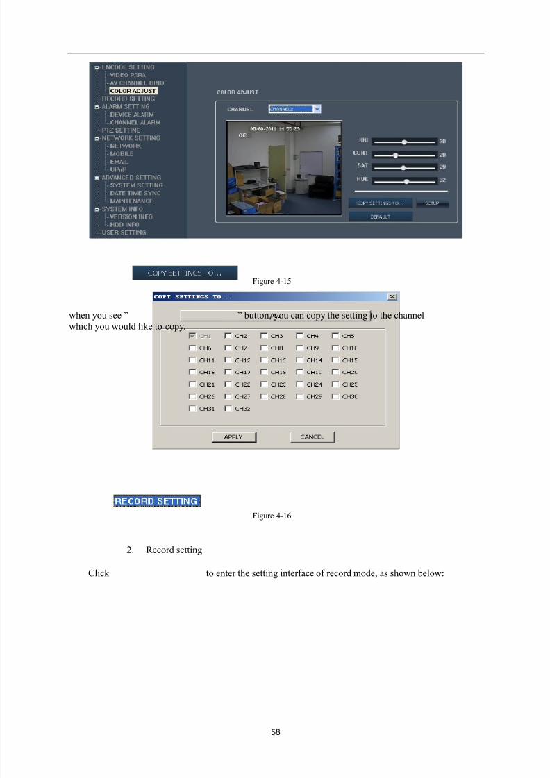
Click to enter the setting of color adjust, you can remotely modify the brightness,
contrast, saturation, and chromaticity, as shown below:
8/10/2019 H.264 Standalone DVR User Manual
http://slidepdf.com/reader/full/h264-standalone-dvr-user-manual 58/90
58
Figure 4-15
when you see ” ” button, you can copy the setting to the channel which you would like to copy.
Figure 4-16
2. Record setting
Click to enter the setting interface of record mode, as shown below:
8/10/2019 H.264 Standalone DVR User Manual
http://slidepdf.com/reader/full/h264-standalone-dvr-user-manual 59/90
59
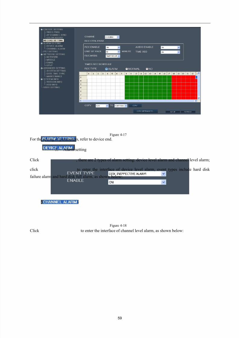
Figure 4-17
For the setting of parameters, refer to device end.
3. Alarm setting
Click , there are 2 types of alarm setting: device level alarm and channel level alarm;
click to enter the interface of device level alarm, event types include hard disk
failure alarm and hard disk full alarm, as shown below:
Figure 4-18
Click to enter the interface of channel level alarm, as shown below:
8/10/2019 H.264 Standalone DVR User Manual
http://slidepdf.com/reader/full/h264-standalone-dvr-user-manual 60/90
60
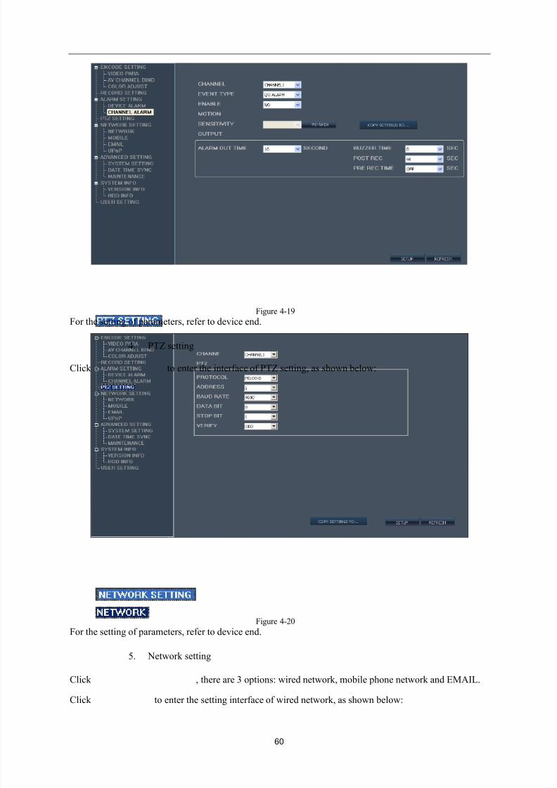
Figure 4-19
For the setting of parameters, refer to device end.
4. PTZ setting
Click to enter the interface of PTZ setting, as shown below:
Figure 4-20
For the setting of parameters, refer to device end.
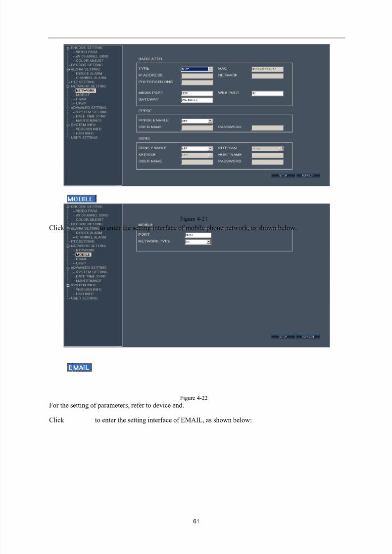
5. Network setting
Click , there are 3 options: wired network, mobile phone network and EMAIL.
Click to enter the setting interface of wired network, as shown below:
8/10/2019 H.264 Standalone DVR User Manual
http://slidepdf.com/reader/full/h264-standalone-dvr-user-manual 61/90
61
Figure 4-21
Click to enter the setting interface of mobile phone network, as shown below:
Figure 4-22
For the setting of parameters, refer to device end.
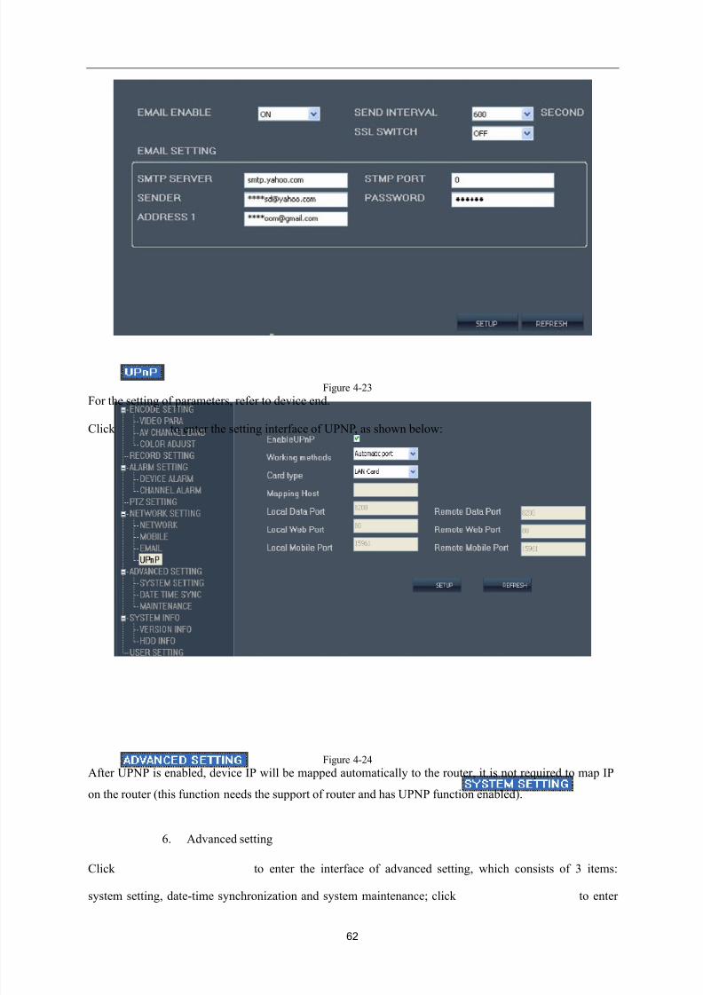
Click to enter the setting interface of EMAIL, as shown below:
8/10/2019 H.264 Standalone DVR User Manual
http://slidepdf.com/reader/full/h264-standalone-dvr-user-manual 62/90
62
Figure 4-23
For the setting of parameters, refer to device end.
Click to enter the setting interface of UPNP, as shown below:
Figure 4-24
After UPNP is enabled, device IP will be mapped automatically to the router, it is not required to map IP
on the router (this function needs the support of router and has UPNP function enabled).
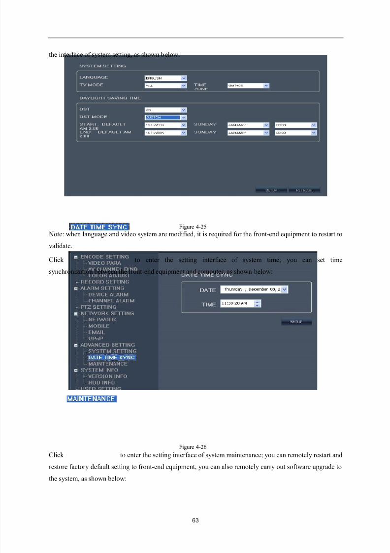
6. Advanced setting
Click to enter the interface of advanced setting, which consists of 3 items:
system setting, date-time synchronization and system maintenance; click to enter
8/10/2019 H.264 Standalone DVR User Manual
http://slidepdf.com/reader/full/h264-standalone-dvr-user-manual 63/90
63
the interface of system setting, as shown below:
Figure 4-25
Note: when language and video system are modified, it is required for the front-end equipment to restart to
validate.
Click to enter the setting interface of system time; you can set time
synchronization between the front-end equipment and computer, as shown below:
Figure 4-26
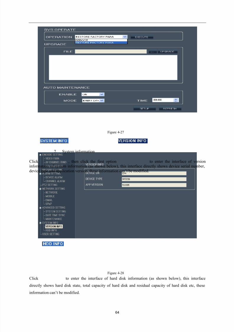
Click to enter the setting interface of system maintenance; you can remotely restart and
restore factory default setting to front-end equipment, you can also remotely carry out software upgrade to
the system, as shown below:
8/10/2019 H.264 Standalone DVR User Manual
http://slidepdf.com/reader/full/h264-standalone-dvr-user-manual 64/90
64
Figure 4-27
7. System information
Click , then click the first option to enter the interface of versioninformation of system information (as shown below), this interface directly shows device serial number,
device type and application version, these inf ormation can’t be modified.
Figure 4-28
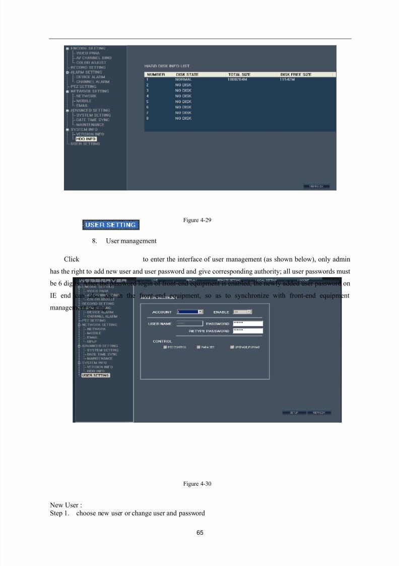
Click to enter the interface of hard disk information (as shown below), this interface
directly shows hard disk state, total capacity of hard disk and residual capacity of hard disk etc, these
information can’t be modified.
8/10/2019 H.264 Standalone DVR User Manual
http://slidepdf.com/reader/full/h264-standalone-dvr-user-manual 65/90
65
Figure 4-29
8. User management
Click to enter the interface of user management (as shown below), only admin
has the right to add new user and user password and give corresponding authority; all user passwords must
be 6 digits. After the password login of front-end equipment is enabled, the newly added user password on
IE end can also log in the front-end equipment, so as to synchronize with front-end equipmentmanagement setting.
Figure 4-30
New User :Step 1. choose new user or change user and password
8/10/2019 H.264 Standalone DVR User Manual
http://slidepdf.com/reader/full/h264-standalone-dvr-user-manual 66/90
66
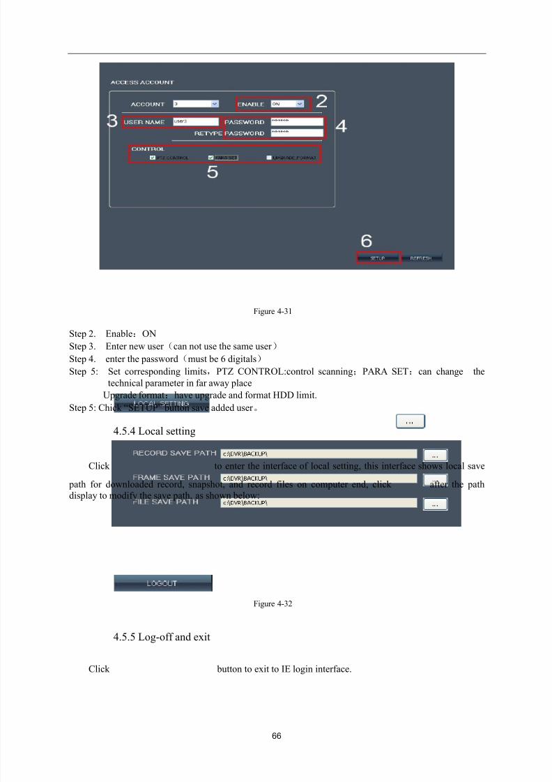
Figure 4-31
Step 2. Enable:ON
Step 3. Enter new user (can not use the same user )
Step 4. enter the password(must be 6 digitals)
Step 5: Set corresponding limits,PTZ CONTROL:control scanning;PARA SET:can change the
technical parameter in far away place
Upgrade format:have upgrade and format HDD limit.
Step 5: Chick “SETUP” button save added user 。
4.5.4 Local setting
Click to enter the interface of local setting, this interface shows local save
path for downloaded record, snapshot, and record files on computer end, click after the path
display to modify the save path, as shown below:
Figure 4-32
4.5.5 Log-off and exit
Click button to exit to IE login interface.
8/10/2019 H.264 Standalone DVR User Manual
http://slidepdf.com/reader/full/h264-standalone-dvr-user-manual 67/90
67
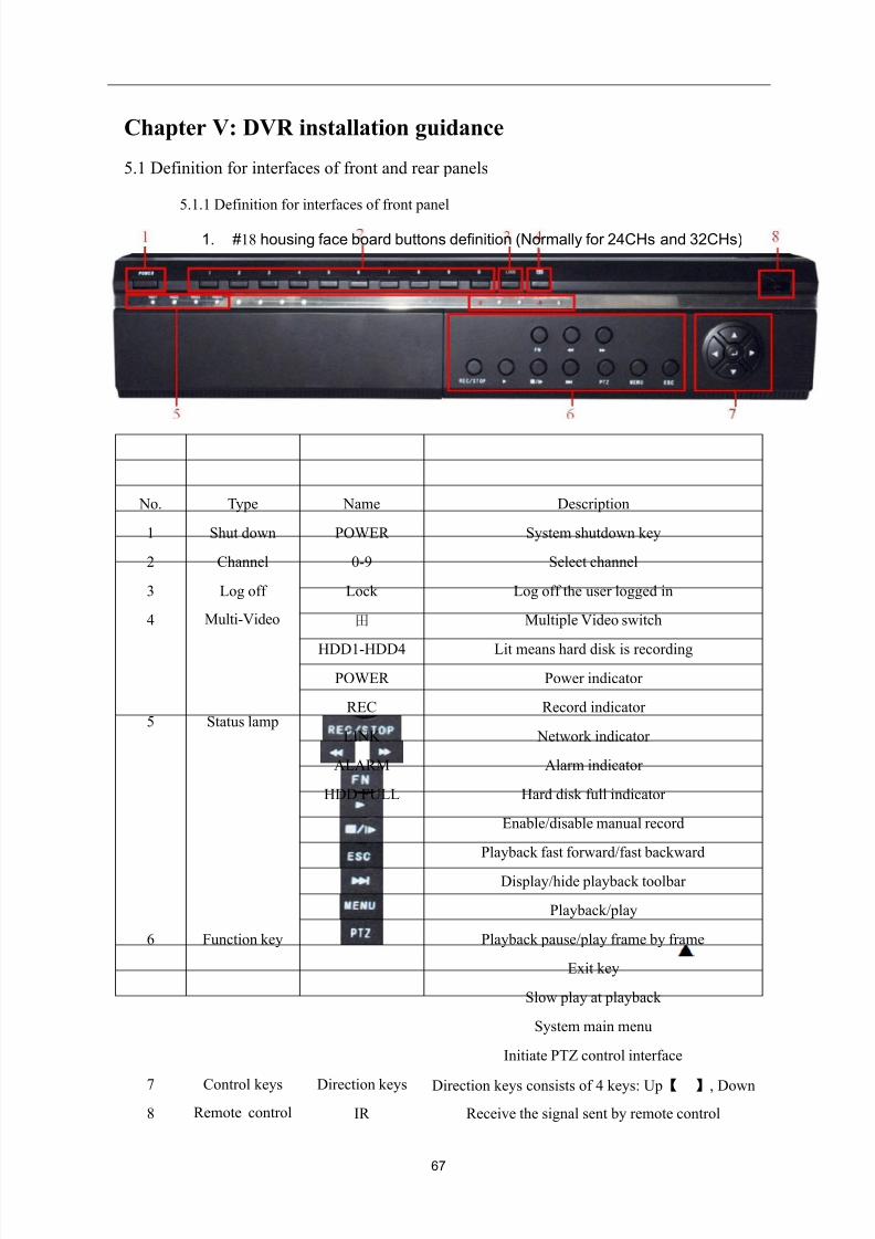
Chapter V: DVR installation guidance
5.1 Definition for interfaces of front and rear panels
5.1.1 Definition for interfaces of front panel
1. #18 housing face board buttons definition (Normally for 24CHs and 32CHs)
No. Type Name Description
1 Shut down POWER System shutdown key
2 Channel 0-9 Select channel
3 Log off Lock Log off the user logged in
4 Multi-Video 田 Multiple Video switch
5 Status lamp
HDD1-HDD4 Lit means hard disk is recording
POWER Power indicator
REC Record indicator
LINK Network indicator
ALARM Alarm indicator
HDD FULL Hard disk full indicator
6 Function key
Enable/disable manual record
Playback fast forward/fast backward
Display/hide playback toolbar
Playback/play
Playback pause/play frame by frame
Exit key
Slow play at playback
System main menu
Initiate PTZ control interface
7 Control keys Direction keys Direction keys consists of 4 keys: Up【 】, Down
8 Remote control IR Receive the signal sent by remote control
8/10/2019 H.264 Standalone DVR User Manual
http://slidepdf.com/reader/full/h264-standalone-dvr-user-manual 68/90
68
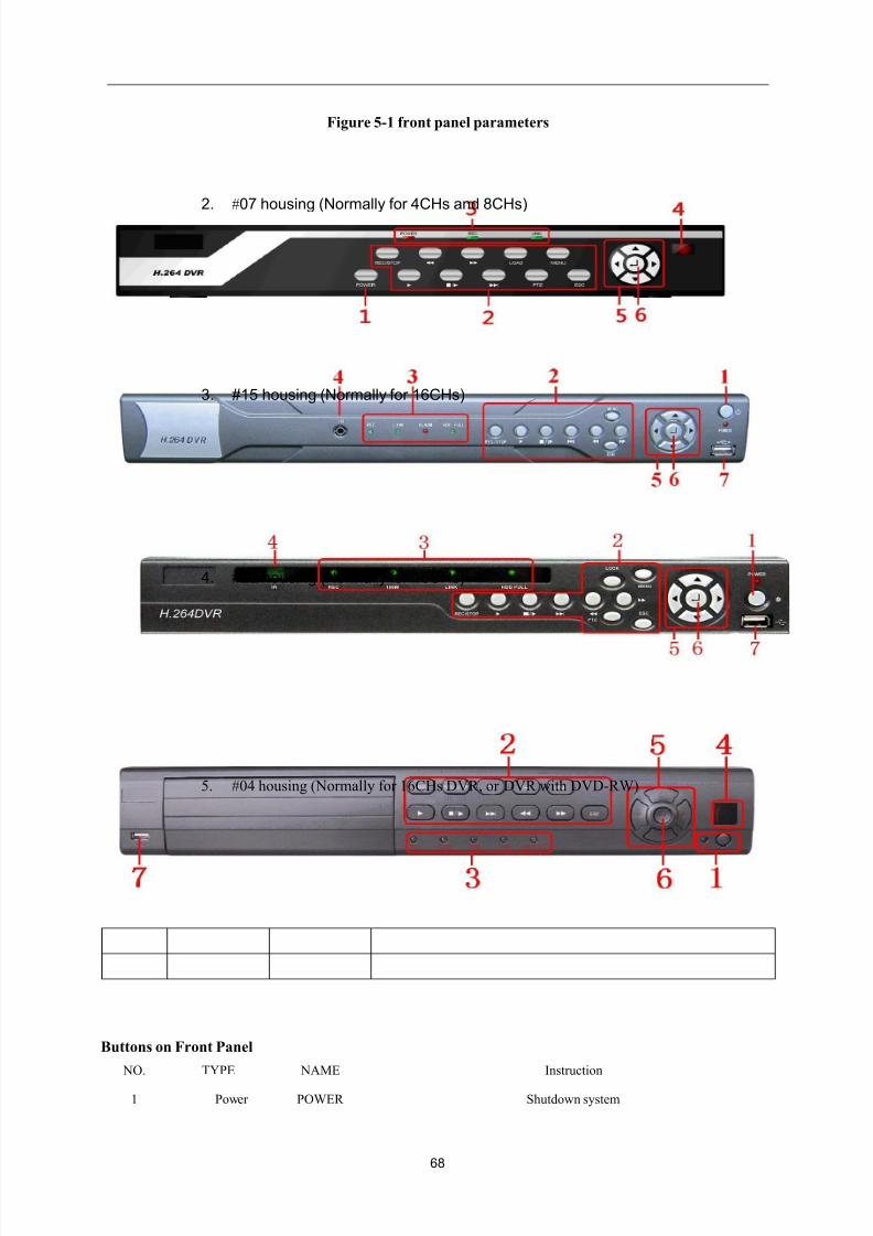
Figure 5-1 front panel parameters
2. #07 housing (Normally for 4CHs and 8CHs)
3. #15 housing (Normally for 16CHs)
4. #22 housing (Normally for 16CHs)
5. #04 housing (Normally for 16CHs DVR, or DVR with DVD-RW)
Buttons on Front Panel
NO. TYPE NAME Instruction
1 Power POWER Shutdown system
8/10/2019 H.264 Standalone DVR User Manual
http://slidepdf.com/reader/full/h264-standalone-dvr-user-manual 69/90
69
2 Function keys
Menu
REC/STOP Recording control buttons
Fast forward/backward playback
LOAD Users Logout
Playback/play
■/ Playback/play by frame
ESC Exit
▏ Slowly playback
PTZ PTZ Controler
MENU Main menu
3 Status indicator
POWER Power
REC Recording
LINK On means network has connected
4 IR receiver IR Remote control receiver
5 Control button Direction key direction key include: up【 】、down【 】、left【 】、right 【 】
four buttons.
6 OKConfirmoperation
Enter
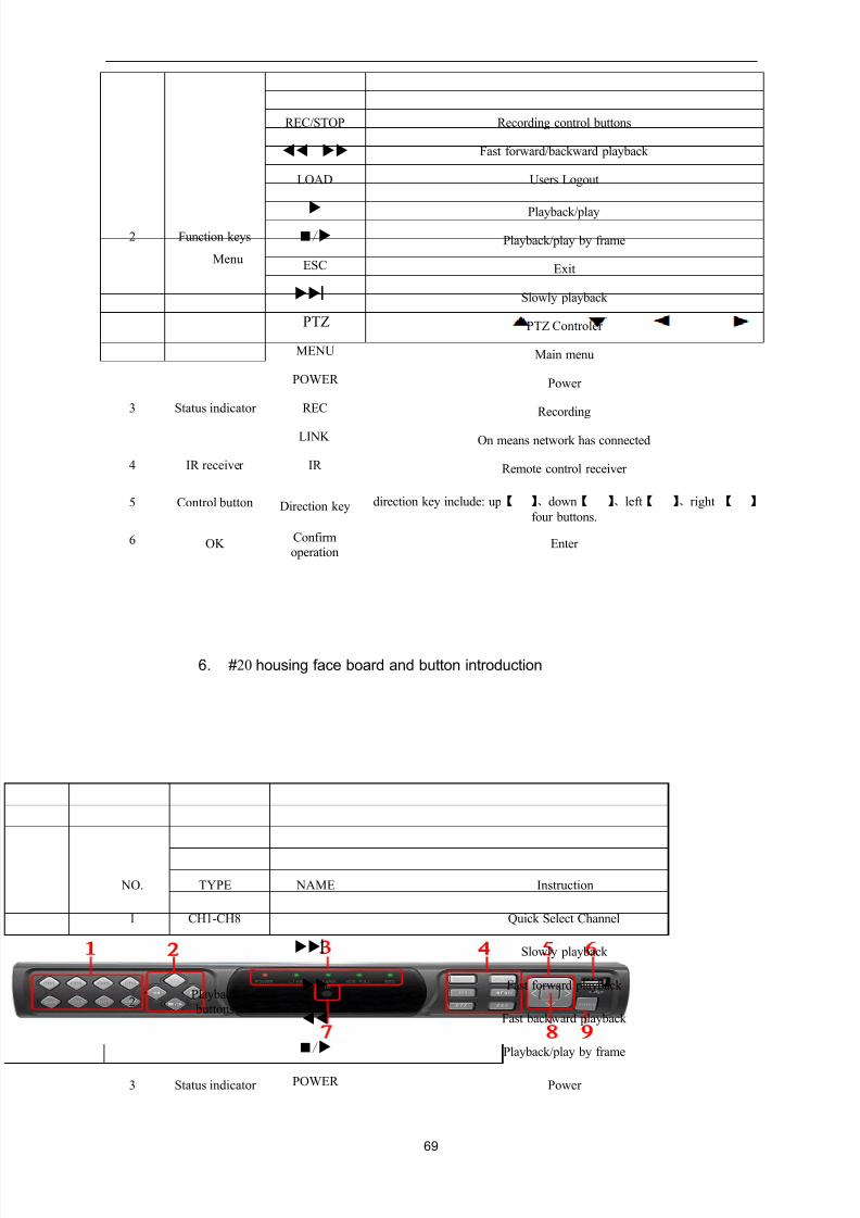
6. #20 housing face board and button introduction
NO. TYPE NAME Instruction
1 CH1-CH8 Quick Select Channel
2Playback buttons
▏ Slowly playback
Fast forward playback
Fast backward playback
■/ Playback/play by frame
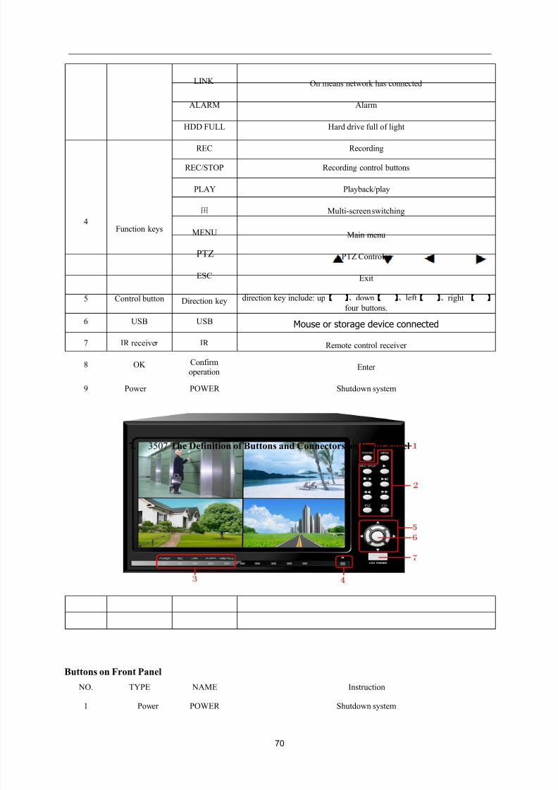
3 Status indicator POWER Power
8/10/2019 H.264 Standalone DVR User Manual
http://slidepdf.com/reader/full/h264-standalone-dvr-user-manual 70/90
70
LINK On means network has connected
ALARM Alarm
HDD FULL Hard drive full of light
REC Recording
4Function keys
REC/STOP Recording control buttons
PLAY Playback/play
田 Multi-screen switching
MENU Main menu
PTZ PTZ Controler
ESC Exit
5 Control button Direction key direction key include: up【 】、down【 】、left【 】、right 【 】
four buttons.
6 USB USB Mouse or storage device connected
7 IR receiver IR Remote control receiver
8 OK Confirmoperation
Enter
9 Power POWER Shutdown system
7. 3507 The Definition of Buttons and Connectors on Front Panel
Buttons on Front Panel
NO. TYPE NAME Instruction
1 Power POWER Shutdown system
8/10/2019 H.264 Standalone DVR User Manual
http://slidepdf.com/reader/full/h264-standalone-dvr-user-manual 71/90
71
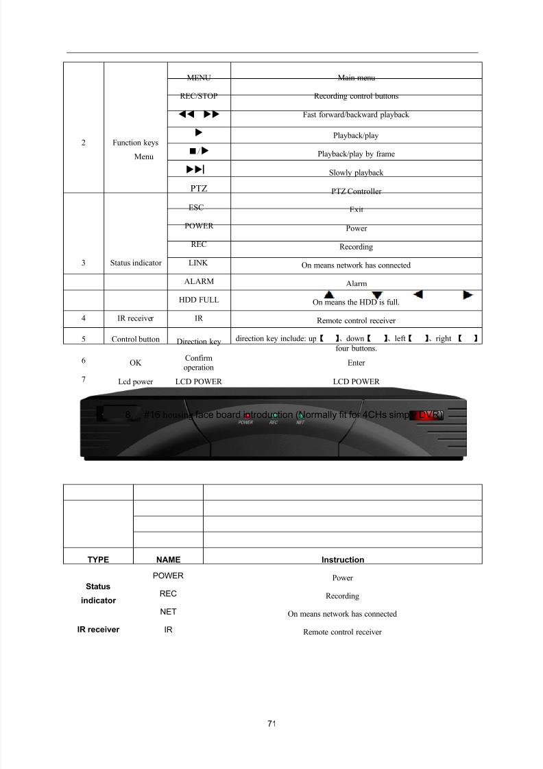
2 Function keys
Menu
MENU Main menu
REC/STOP Recording control buttons
Fast forward/backward playback
Playback/play
■/ Playback/play by frame
▏ Slowly playback
PTZ PTZ Controller
ESC Exit
3 Status indicator
POWER Power
REC Recording
LINK
On means network has connectedALARM Alarm
HDD FULL On means the HDD is full.
4 IR receiver IR Remote control receiver
5 Control button Direction key direction key include: up【 】、down【 】、left【 】、right 【 】
four buttons.
6 OKConfirmoperation
Enter
7 Lcd power LCD POWER LCD POWER
8. #16 housing face board introduction (Normally fit for 4CHs simply DVR)
TYPE NAME Instruction
Status
indicator
POWER Power
REC Recording
NET On means network has connected
IR receiver IR Remote control receiver
8/10/2019 H.264 Standalone DVR User Manual
http://slidepdf.com/reader/full/h264-standalone-dvr-user-manual 72/90
72
5.1.2 Definition for interfaces of rear pane
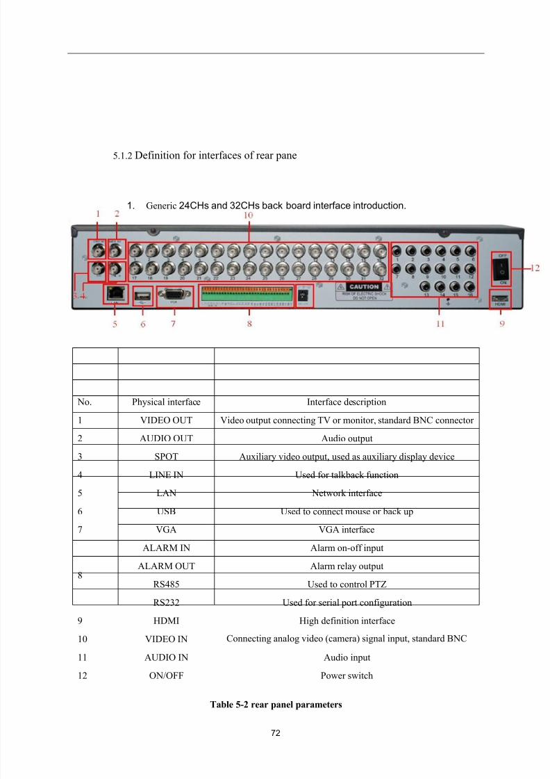
1. Generic 24CHs and 32CHs back board interface introduction.
No. Physical interface Interface description
1 VIDEO OUT Video output connecting TV or monitor, standard BNC connector
2 AUDIO OUT Audio output
3 SPOT Auxiliary video output, used as auxiliary display device
4 LINE IN Used for talkback function
5 LAN Network interface
6 USB Used to connect mouse or back up
7 VGA VGA interface
8
ALARM IN Alarm on-off input
ALARM OUT Alarm relay output
RS485 Used to control PTZ
RS232 Used for serial port configuration
9 HDMI High definition interface
10 VIDEO IN Connecting analog video (camera) signal input, standard BNC
11 AUDIO IN Audio input
12 ON/OFF Power switch
Table 5-2 rear panel parameters
8/10/2019 H.264 Standalone DVR User Manual
http://slidepdf.com/reader/full/h264-standalone-dvr-user-manual 73/90
73
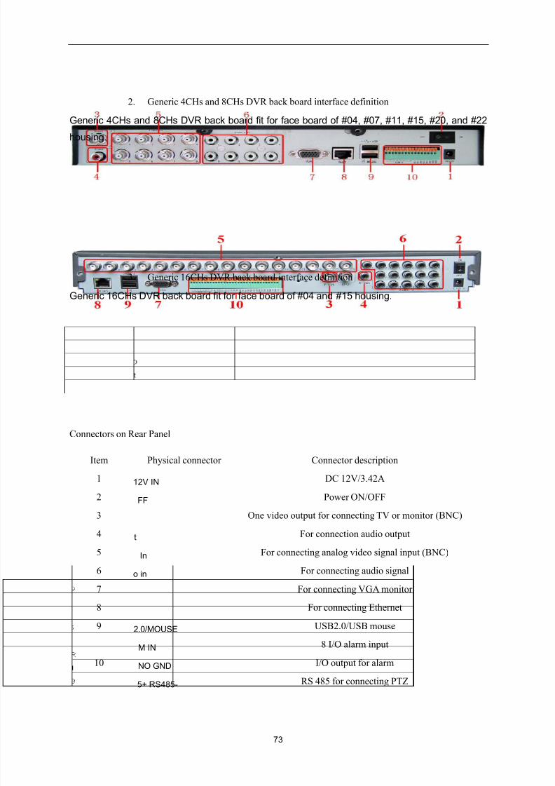
2. Generic 4CHs and 8CHs DVR back board interface definition
Generic 4CHs and 8CHs DVR back board fit for face board of #04, #07, #11, #15, #20, and #22
housing.
3. Generic 16CHs DVR back board interface definition
Generic 16CHs DVR back board fit for face board of #04 and #15 housing.
Connectors on Rear Panel
Item Physical connector Connector description
1 12V IN DC 12V/3.42A
2 FF Power ON/OFF
3 One video output for connecting TV or monitor (BNC)
4 t For connection audio output
5 In For connecting analog video signal input (BNC)
6 o in For connecting audio signal
7 For connecting VGA monitor
8 For connecting Ethernet
9 2.0/MOUSE USB2.0/USB mouse
10
M IN 8 I/O alarm input
NO GND I/O output for alarm
5+ RS485-
RS 485 for connecting PTZ
8/10/2019 H.264 Standalone DVR User Manual
http://slidepdf.com/reader/full/h264-standalone-dvr-user-manual 74/90
74
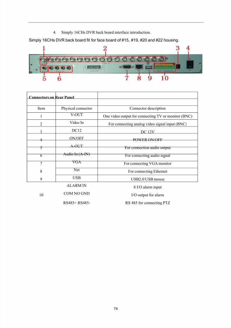
4. Simply 16CHs DVR back board interface introduction.
Simply 16CHs DVR back board fit for face board of #15, #19, #20 and #22 housing.
Connectors on Rear Panel
Item Physical connector Connector description
1 V-OUT One video output for connecting TV or monitor (BNC)
2 Video In For connecting analog video signal input (BNC)
3 DC12 DC 12V
4 ON/OFF POWER ON/OFF
5 A-OUT For connection audio output
6 Audio In (A-IN) For connecting audio signal
7 VGA For connecting VGA monitor
8 Net
For connecting Ethernet
9 USB USB2.0/USB mouse
10
ALARM IN 8 I/O alarm input
COM NO GND I/O output for alarm
RS485+ RS485- RS 485 for connecting PTZ
8/10/2019 H.264 Standalone DVR User Manual
http://slidepdf.com/reader/full/h264-standalone-dvr-user-manual 75/90
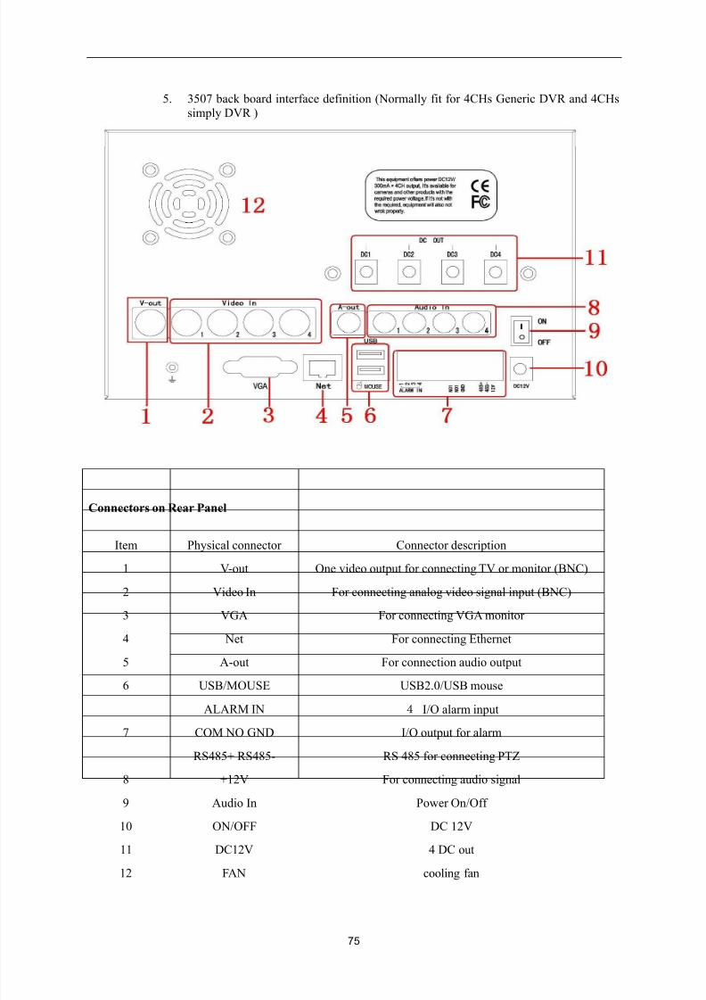
75
5. 3507 back board interface definition (Normally fit for 4CHs Generic DVR and 4CHssimply DVR )
Connectors on Rear Panel
Item Physical connector Connector description
1 V-out One video output for connecting TV or monitor (BNC)
2 Video In For connecting analog video signal input (BNC)
3 VGA For connecting VGA monitor
4 Net For connecting Ethernet
5 A-out For connection audio output
6 USB/MOUSE USB2.0/USB mouse
7
ALARM IN 4 I/O alarm input
COM NO GND I/O output for alarm
RS485+ RS485- RS 485 for connecting PTZ
8 +12V For connecting audio signal
9 Audio In Power On/Off
10 ON/OFF DC 12V
11 DC12V 4 DC out
12 FAN cooling fan
8/10/2019 H.264 Standalone DVR User Manual
http://slidepdf.com/reader/full/h264-standalone-dvr-user-manual 76/90
76
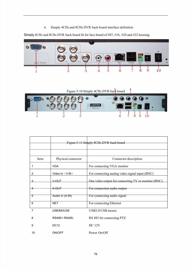
6. Simply 4CHs and 8CHs DVR back board interface definition
Simply 4CHs and 8CHs DVR back board fit for face board of #07, #16, #20 and #22 housing.
Figure 5-10 Simply 4CHs DVR back board
Figure 5-11 Simply 8CHs DVR back board
Item Physical connector Connector description
1 VGA For connecting VGA monitor
2 Video In(V-IN) For connecting analog video signal input (BNC)
3 V-OUT One video output for connecting TV or monitor (BNC)
4 A-OUT For connection audio output
5 Audio In (A-IN) For connecting audio signal
6 NET For connecting Ethernet
7 USB/MOUSE USB2.0/USB mouse
8 RS485+ RS485- RS 485 for connecting PTZ
9 DC12 DC 12V
10 ON/OFF Power On/Off
8/10/2019 H.264 Standalone DVR User Manual
http://slidepdf.com/reader/full/h264-standalone-dvr-user-manual 77/90
77
5.2 Alarm post interface
Connection method of alarm post: firstly strip the cable to be connected, then use a small screwdriver
to jack up orange part, put the cable into the receptacle then loosen the screwdriver to fasten.
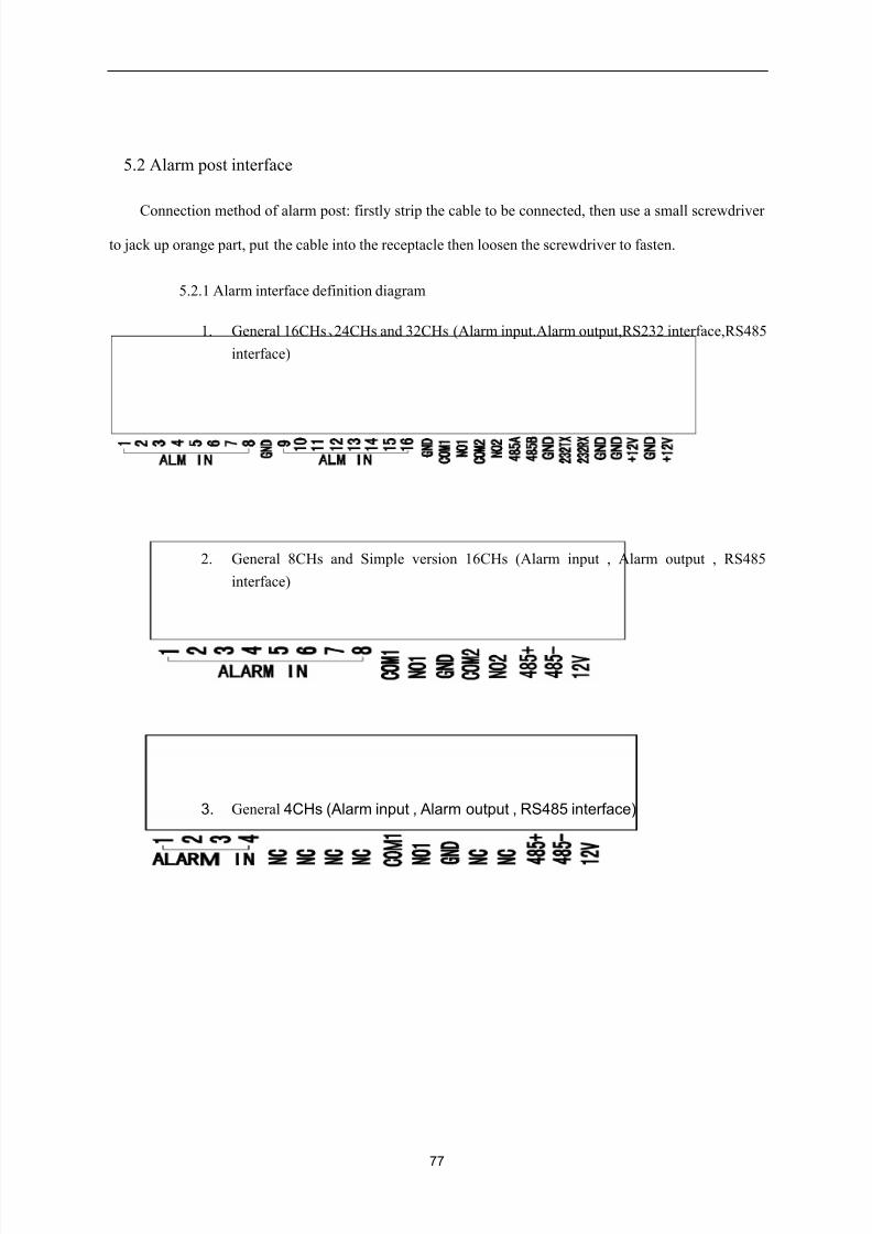
5.2.1 Alarm interface definition diagram
1. General 16CHs、24CHs and 32CHs (Alarm input.Alarm output,RS232 interface,RS485
interface)
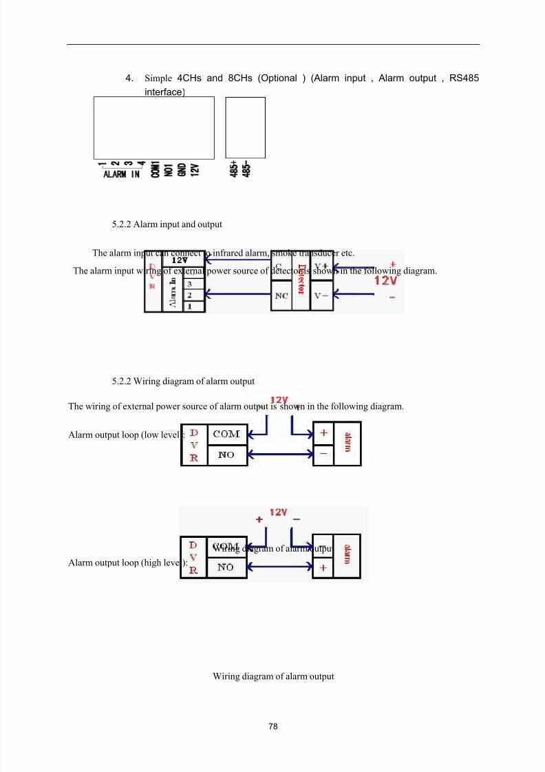
2. General 8CHs and Simple version 16CHs (Alarm input , Alarm output , RS485
interface)
3. General 4CHs (Alarm input , Alarm output , RS485 interface)
8/10/2019 H.264 Standalone DVR User Manual
http://slidepdf.com/reader/full/h264-standalone-dvr-user-manual 78/90
78
4. Simple 4CHs and 8CHs (Optional ) (Alarm input , Alarm output , RS485
interface)
5.2.2 Alarm input and output
The alarm input can connect to infrared alarm, smoke transducer etc.
The alarm input wiring of external power source of detector is shown in the following diagram.
5.2.2 Wiring diagram of alarm output
The wiring of external power source of alarm output is shown in the following diagram.
Alarm output loop (low level):
Wiring diagram of alarm output
Alarm output loop (high level):
Wiring diagram of alarm output
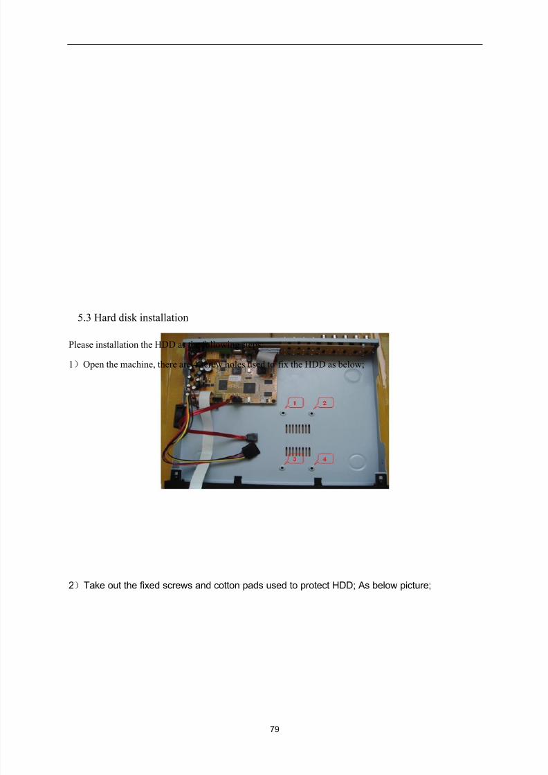
8/10/2019 H.264 Standalone DVR User Manual
http://slidepdf.com/reader/full/h264-standalone-dvr-user-manual 79/90
79
5.3 Hard disk installation
Please installation the HDD as the following steps:
1)Open the machine, there are 4 screw holes used to fix the HDD as below;
2)Take out the fixed screws and cotton pads used to protect HDD; As below picture;
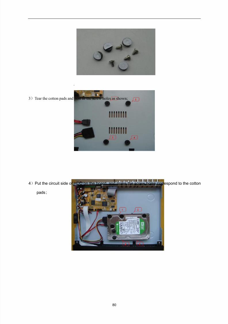
8/10/2019 H.264 Standalone DVR User Manual
http://slidepdf.com/reader/full/h264-standalone-dvr-user-manual 80/90
80
.
3)Tear the cotton pads and post in the screw holes as shown;
4)Put the circuit side of HDD on the board, and make the screw holes correspond to the cotton
pads;
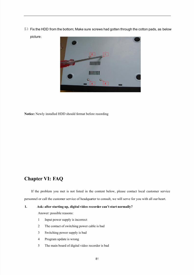
8/10/2019 H.264 Standalone DVR User Manual
http://slidepdf.com/reader/full/h264-standalone-dvr-user-manual 81/90
81
5)Fix the HDD from the bottom; Make sure screws had gotten through the cotton pads, as below
picture;
Notice: Newly installed HDD should format before recording
Chapter VI: FAQ
If the problem you met is not listed in the content below, please contact local customer service
personnel or call the customer service of headquarter to consult, we will serve for you with all our heart.
1. Ask: after starting up, digital video recorder can’t start normally?
Answer: possible reasons:
1 Input power supply is incorrect
2 The contact of switching power cable is bad
3 Switching power supply is bad
4 Program update is wrong
5 The main board of digital video recorder is bad
8/10/2019 H.264 Standalone DVR User Manual
http://slidepdf.com/reader/full/h264-standalone-dvr-user-manual 82/90
82
2. Ask: digital video recorder will restart automatically or often down several minutes after
starting up
Answer: possible reasons:
1 Input voltage is unstable or too low
2 Hard disk has bad track or hard disk cable is bad
3 The power of switching power supply is not enough
4 The video signal of front end is unstable
5 Bad ventilation, too much dust, the operating conditions of machine are too severe
6 The contact between main board and other auxiliary board is bad
7 Hardware failure of digital video recorder
3. Ask: single channel, multiple channels, all Video have no output
Answer: possible reasons:
1 Please check the power supply connecting camera for loose
2 Please check the connecting wire of video output and input on the rear panel of DVR
3 Directly insert the video source into display device to judge if it is the problem of video
source or display device
4 Check image brightness to see if it becomes 0, restore to default setting
5 No video input signal or the signal is too weak
6 Preview closed is set in display setting
7 Hardware failure of digital video recorder
4. Ask: can’t record normally after starting up, a “H” is prompted on the interface
Answer: possible reasons:
1 Check if DC12V power adapter is adopted by the machine
2 Check if new hard disk has been formatted on the local host
3 The contacts of hard disk power cable, data cable are bad or damaged
4 Hard disk is damaged
5 SATA port of main board is damaged
5. Ask: what’s the meanings of “R” “M” “I” “H” “W” prompted on direct connection picture
Answer:
1 “R” means that record is being carried out on the channel
2 “M” means that motion detection is triggered on the channel
3 “I” means that external I/O alarm is triggered on the channel
4 “H” means that the device has no hard disk connected or hard disk failure or disk full
8/10/2019 H.264 Standalone DVR User Manual
http://slidepdf.com/reader/full/h264-standalone-dvr-user-manual 83/90
83
5 “W” means that current system time conflicts with time of record file existed on hard disk
6. Ask: real time image problem, such as video image color, brightness have serious distortion
Answer: possible reasons:
1 When BNC is used for output, the selection of PAL system and NTSC system is incorrect,
the image will become black and white
2 Digital video recorder and the impedance of monitor not matched
3 Video transmission distance is too long or the fading of video transmission cable is too high
4 The settings of color, brightness etc of digital video recorder are incorrect
7. Ask: no sound in listening
Answer: possible reasons:
1 Check if active pickup and active sound box are adopted, you can judge by directly short
the signal cables of both
2 Whether the video channel with audio source connected is activated, you can single click
the channel to be in full screen to judge
3 Hardware failure of digital video recorder
8. Ask: there is sound in monitoring, but no sound in playback
Answer: possible reasons:
1 Setting problem: audio record option has not been opened
2 Whether mute is set in playback interface
9. Ask: time display is wrong
Answer: possible reasons:
1 Setting is wrong, or the time is modified but “Modify date & time” is not pressed to validate
2 The contact of battery is bad
3 The service time of battery is too long, please replace the battery
10. Ask: why “Stop record” by clicking right mouse has no function, how to stop record
Answer:
1 The “Stop record” key of right mouse is used to stop manual record, it can’t be used to stop
the record set in starting record or record schedule
2 If it is required to stop record, please enter into record schedule, set the time interval as no
record
11. Ask: motion detection has no function
Answer: possible reasons:
1 The setting of motion detection zone is not appropriate
2 The sensitivity is too low
8/10/2019 H.264 Standalone DVR User Manual
http://slidepdf.com/reader/full/h264-standalone-dvr-user-manual 84/90
84
12. Ask: error in DVD/CD rewritable drive/USB device
Answer: possible reasons:
1 Data quantity exceeds the capacity of backup device, which will result in CD burning error
2 Backup device is not compatible
3 Backup device is damaged
13. Ask: the remote control can’t control
Answer: possible reasons:
1 The address of remote control is wrong
2 The distance of remote control is too far or the angle is too deflective
3 The battery of remote control is used up
4 The remote control is damaged or the front panel of video recorder is damaged
14. Ask: can’t login WEB
Answer: possible reasons:
1 Check if the network is connected, check if the LINK or 100M LED on panel displays
correctly; use ping xxx.xxx.xxx.xxx (the IP address of the DVR) to check if the network is
connected
2 Windows XP or Vista operation system is recommended, IE6.0 or IE7.0 browser is adopted
3 ActiveX control is inhibited, please install ActiveX control manually
4 No dx8.1 or above version is installed, upgrade the driver of display card
15. Ask: there is mosaic in network preview Video and record file playback or no image at all
Answer: possible reasons:
1 If DVR is accessed through Internet, when IE is used to login, please select “WAN” in
“Network environment”, and select appropriate network bandwidth in “Setting > System
setting > Network environment” option.
2 Please try right key “Close window”, then “Open window”
16. Ask: when setting is carried out at IE end, why “Other user is configuring…” window pops
up
Answer: possible reasons:
1 This may means that others are setting DVR. Please check if the configuration interface of
DVR end is in open state, please exit.
17. Ask: digital video recorder can’t control PTZ
Answer: possible reasons:
1 Front end PTZ failure
2 PTZ decoder setting, wiring, installation are incorrect
8/10/2019 H.264 Standalone DVR User Manual
http://slidepdf.com/reader/full/h264-standalone-dvr-user-manual 85/90
85
3 Wiring is incorrect
4 The setting of PTZ in digital video recorder is incorrect
5 PTZ decoder and the protocol of digital video recorder not matched
6 PTZ decoder and the address of digital video recorder not matched
7 When multiple decoders are connected, the farthest end of A B lines of PTZ decoder should
be added with a 120 Ω resistor to eliminate reflection and make impedance matching,
otherwise unstable PTZ control may be resulted.
8 The distance is too far
18. Ask: how much capacity is occupied in hard disk by record per hour
Answer:
1 For audio record, about 14Mbyte capacity is occupied for each channel
2 The capacity occupied in hard disk by video record depends on the selection of “Record
mode > bit rate”: excellent, good, medium, and also depends on the motion amount of
pictures within the time interval; if the picture is still, then the consumption of hard disk is
lower; if the picture is motive, then the consumption is higher. When “excellent” is selected,
about 320Mbyte capacity is occupied for each channel of video per hour; when “good” is
selected, and the pictures are still or small motive, then about 50~100Mbyte capacity is
occupied for each channel of video per hour; if the pictures are large motive or many small
motive, then about 100~200Mbyte capacity is occupied for each channel of video per hour;
when “medium” is selected, and the pictures are still or small motive, about 50~100Mbyte
capacity is occupied for each channel of video per hour; if the pictures are large motive or
many small motive, then about 100~150Mbyte capacity is occupied for each channel of
video per hour;
19. Ask: I/O alarm has no function
Answer: possible reasons:
1 Alarm setting is incorrect
2 Alarm wiring is incorrect
3 Alarm input signal is incorrect
4 One alarm device connects to 2 circuits at the same time
Chapter VII: APPENDIX
Pppendix 1 E-Video
Operation Steps
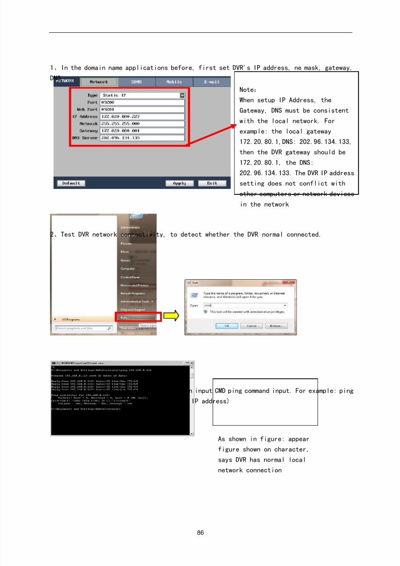
8/10/2019 H.264 Standalone DVR User Manual
http://slidepdf.com/reader/full/h264-standalone-dvr-user-manual 86/90
86
1、In the domain name applications before, first set DVR's IP address, ne mask, gateway,
DNS
2、Test DVR network connectivity, to detect whether the DVR normal connected.
In computer host start menu-run inside, in input CMD ping command input. For example: ping
192.168.1. XXX (this IP for the DVR set IP address)
Note:
When setup IP Address, theGateway, DNS must be consistent
with the local network. For
example: the local gateway
172.20.80.1,DNS: 202.96.134.133,
then the DVR gateway should be
172.20.80.1, the DNS:
202.96.134.133. The DVR IP address
setting does not conflict with
other computers or network devices
in the network
As shown in figure: appear
figure shown on character,
says DVR has normal local
network connection
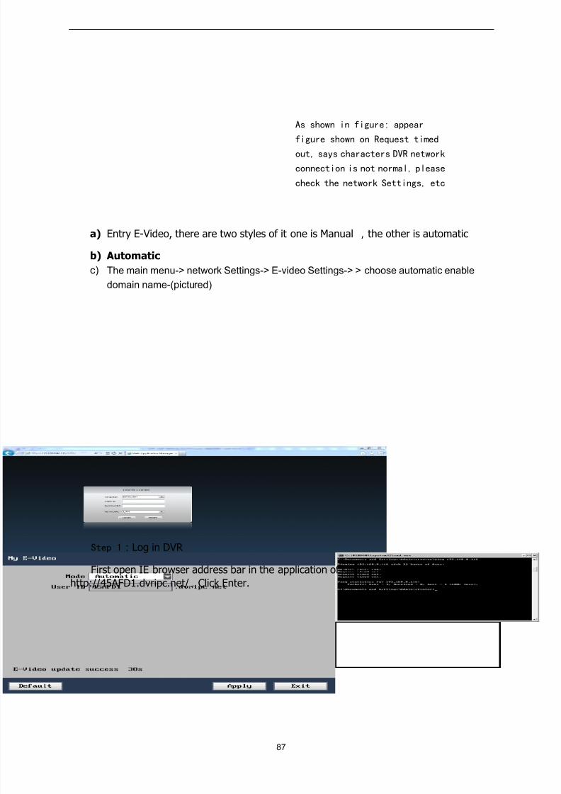
8/10/2019 H.264 Standalone DVR User Manual
http://slidepdf.com/reader/full/h264-standalone-dvr-user-manual 87/90
87
a) Entry E-Video, there are two styles of it one is Manual ,the other is automatic
b) Automatic
c) The main menu-> network Settings-> E-video Settings-> > choose automatic enable
domain name-(pictured)
Step 1:Log in DVR
First open IE browser address bar in the application of success in input domain name:
http://45AFD1.dvripc.net/,Click Enter.
As shown in figure: appear
figure shown on Request timedout, says characters DVR network
connection is not normal, please
check the network Settings, etc
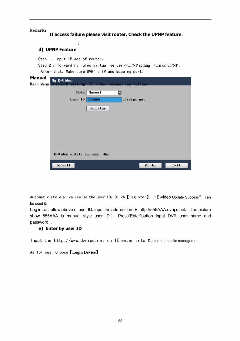
8/10/2019 H.264 Standalone DVR User Manual
http://slidepdf.com/reader/full/h264-standalone-dvr-user-manual 88/90
88
Remark:
If access failure please visit router, Check the UPNP feature.
d) UPNP Feature
Step 1:input IP add of router, Step 2 :forwarding rules-virtual server ->UPNP setting,turn on UPNP。
After that,Make sure DVR’s IP and Mapping port.
Manual
Main Menu->Network setting ->E-Video->Manual(as follow)
Automatic style allow revise the user ID,Click【register】 “E-video Update Success” can
be used it,
Log in:as follow above of user ID,input the address on IE: http://555AAA.dvripc.net/ (as picture
show 555AAA is manual style user ID ), Press“Enter”button input DVR user name and
password 。
e) Enter by user ID
Input the http://www.dvripc.net on IE enter into Domain name site management
As follows,Choose【Login Device】
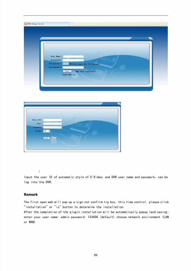
8/10/2019 H.264 Standalone DVR User Manual
http://slidepdf.com/reader/full/h264-standalone-dvr-user-manual 89/90
89
Input the user ID of automatic style of E-Video,and DVR user name and passwork,can be
log into the DVR。
Remark
The first open web will pop up a sign not confirm tip box, this time control, please click
"installation" or "is" button to determine the installation.
After the completion of the plugin installation will be automatically popup land casing:
enter your user name: admin password: 123456 (default) choose network environment (LAN
or WAN)
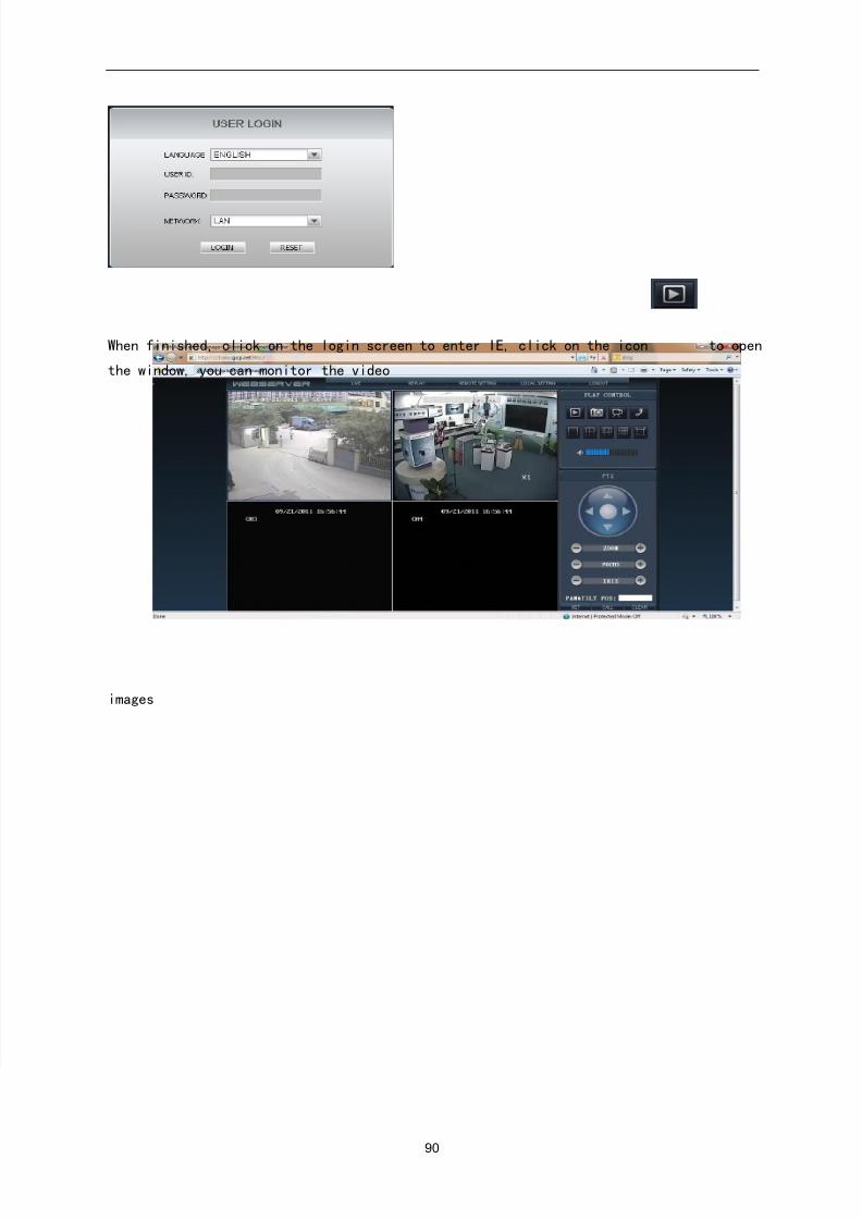
8/10/2019 H.264 Standalone DVR User Manual
http://slidepdf.com/reader/full/h264-standalone-dvr-user-manual 90/90
When finished, click on the login screen to enter IE, click on the icon to open
the window, you can monitor the video
images