H1 Basic Review. - King Mongkut's Institute of Technology Ladkrabang
39
Transcript of H1 Basic Review. - King Mongkut's Institute of Technology Ladkrabang


© 1999 – 2005 Fieldbus Foundation2
H1 Basic Review.
• What is Fieldbus?• Integrated Architecture.
H1 Benefits.
• More data is available.• Expanded view of Process and Instruments.• Reduction in System Hardware.• Wiring Saving.• Summary.• 4-20mA versus Fieldbus.
FOUNDATION Fieldbus Technology.
• H1 network review technology.• Intrinsic Safety.• DD and CFF Files.• Typical Fieldbus installation.• Fieldbus Components.• H1 Fieldbus Model.
Fieldbus Basics Agenda
© 1999 – 2005 Fieldbus Foundation3
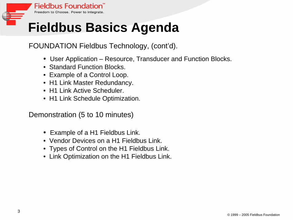
FOUNDATION Fieldbus Technology, (cont’d).
• User Application – Resource, Transducer and Function Blocks.• Standard Function Blocks.• Example of a Control Loop.• H1 Link Master Redundancy.• H1 Link Active Scheduler.• H1 Link Schedule Optimization.
Demonstration (5 to 10 minutes)
• Example of a H1 Fieldbus Link.• Vendor Devices on a H1 Fieldbus Link.• Types of Control on the H1 Fieldbus Link.• Link Optimization on the H1 Fieldbus Link.
Fieldbus Basics Agenda

© 1999 – 2005 Fieldbus Foundation4
H1 Basic ReviewH1 Basic Review

© 1999 – 2005 Fieldbus Foundation5
What is Fieldbus?1. A fieldbus is an all-digital, serial two-way, multi-drop communication System.
2. H1 link (31.25kbps) interconnects field equipment (Sensors, Actuators & I/O).
3. HSE (High Speed Ethernet, 100mbps) provides integration of high speed controllers, subsystems (via Linking Device) and data servers and workstation.
Data Servers
© 1999 – 2005 Fieldbus Foundation6
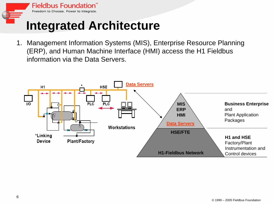
Integrated Architecture1. Management Information Systems (MIS), Enterprise Resource Planning
(ERP), and Human Machine Interface (HMI) access the H1 Fieldbus information via the Data Servers.
Data Servers
Business Enterprise and Plant Application Packages
H1 and HSEFactory/Plant Instrumentation and Control devicesH1-Fieldbus Network
HSE/FTE
Data Servers
MISERPHMI
© 1999 – 2005 Fieldbus Foundation7
H1 BenefitsH1 Benefits
© 1999 – 2005 Fieldbus Foundation8
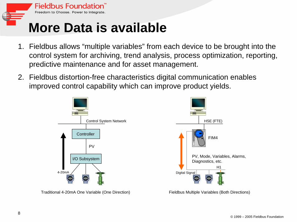
More Data is available1. Fieldbus allows “multiple variables” from each device to be brought into the
control system for archiving, trend analysis, process optimization, reporting, predictive maintenance and for asset management.
2. Fieldbus distortion-free characteristics digital communication enables improved control capability which can improve product yields.
Traditional 4-20mA One Variable (One Direction)
PV
Control System Network
Controller
I/O Subsystem
4-20mA
Fieldbus Multiple Variables (Both Directions)
PV, Mode, Variables, Alarms, Diagnostics, etc.
HSE (FTE)
FIM4
H1Digital Signal
© 1999 – 2005 Fieldbus Foundation9
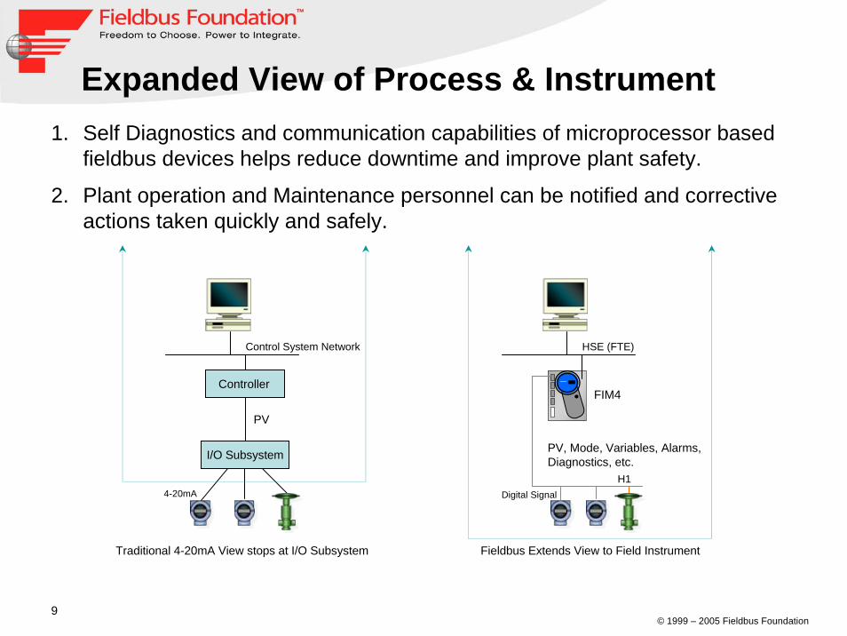
Expanded View of Process & Instrument1. Self Diagnostics and communication capabilities of microprocessor based
fieldbus devices helps reduce downtime and improve plant safety.
2. Plant operation and Maintenance personnel can be notified and corrective actions taken quickly and safely.
Fieldbus Extends View to Field Instrument
PV, Mode, Variables, Alarms, Diagnostics, etc.
HSE (FTE)
FIM4
Traditional 4-20mA View stops at I/O Subsystem
PV
Control System Network
Controller
I/O Subsystem
H1Digital Signal4-20mA
© 1999 – 2005 Fieldbus Foundation10
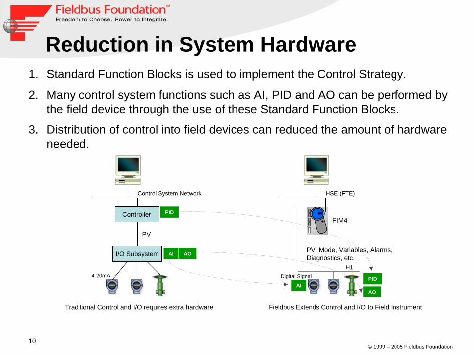
Reduction in System Hardware1. Standard Function Blocks is used to implement the Control Strategy.
2. Many control system functions such as AI, PID and AO can be performed by the field device through the use of these Standard Function Blocks.
3. Distribution of control into field devices can reduced the amount of hardware needed.
Fieldbus Extends Control and I/O to Field Instrument
PV, Mode, Variables, Alarms, Diagnostics, etc.
HSE (FTE)
FIM4
Traditional Control and I/O requires extra hardware
PV
Control System Network
Controller
I/O Subsystem
PID
AI AO
PIDAI
AO
H1Digital Signal4-20mA

© 1999 – 2005 Fieldbus Foundation11
Wiring Savings1. The H1 fieldbus allows many devices to be connected to a single wire pair.
2. This results in less wire, fewer intrinsic safety barriers and fewer marshaling cabinets.
One I.S Barrier, One Wire for Many Devices
HSE (FTE)
FIM4
Traditional 4-20mA wiring, One I.S Barrier, One wiring for each Device
PV
Control System Network
Controller
I/O Subsystem
PID
I.S
AO
H1I.S I.S I.S
Digital Signal
PV, Mode, Variables, Alarms, Diagnostics, etc.
4-20mA
© 1999 – 2005 Fieldbus Foundation12
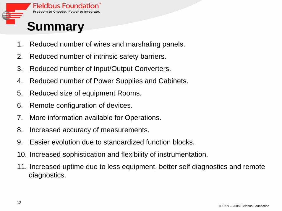
Summary1. Reduced number of wires and marshaling panels.
2. Reduced number of intrinsic safety barriers.
3. Reduced number of Input/Output Converters.
4. Reduced number of Power Supplies and Cabinets.
5. Reduced size of equipment Rooms.
6. Remote configuration of devices.
7. More information available for Operations.
8. Increased accuracy of measurements.
9. Easier evolution due to standardized function blocks.
10. Increased sophistication and flexibility of instrumentation.
11. Increased uptime due to less equipment, better self diagnostics and remote diagnostics.

© 1999 – 2005 Fieldbus Foundation13
4-20mA versus Fieldbus
4-20mA
P.S.4-20mA
Fieldbus
P.S.
1. A H1 fieldbus retains and optimizes the desired features of the 4-20mA analog system:
- single Loop integrity.- a standardized physical interface to the wire.- a bus-powered devices on a single wire pair.- intrinsic safety options.
2. In addition, FOUNDATION Fieldbus enables:
- increased capabilities (due to full digital communication).
- reduced wiring and terminations (multiple device on one wire).
- increased selection of suppliers (due to interoperability).
- reduced control room loading (control on wire).- connection to HSE backbone.

© 1999 – 2005 Fieldbus Foundation14
FOUNDATION fieldbusFOUNDATION fieldbusTechnologyTechnology

© 1999 – 2005 Fieldbus Foundation15
H1 Network Review
HSE (FTE)
FIM4
H1Digital Signal
1900 meters
1. Multi-Drop wire pair with Power and Signal on same cable.
2. Support Intrinsic Safety.
3. Fault Tolerant, can have multiple Link Masters.
4. Function Blocks built into Field Devices.
5. Control on the Wire – single loop integrity
6. Distance up to 1900 meters.
7. Can add Repeaters toextend > 1900 meters.
8. Max. of 4 repeaters canbe used to a maximumdistance of 9500 meters.
R
Distance > 1900 meters
H1 Digital Signal
Fieldbus Signal
© 1999 – 2005 Fieldbus Foundation16
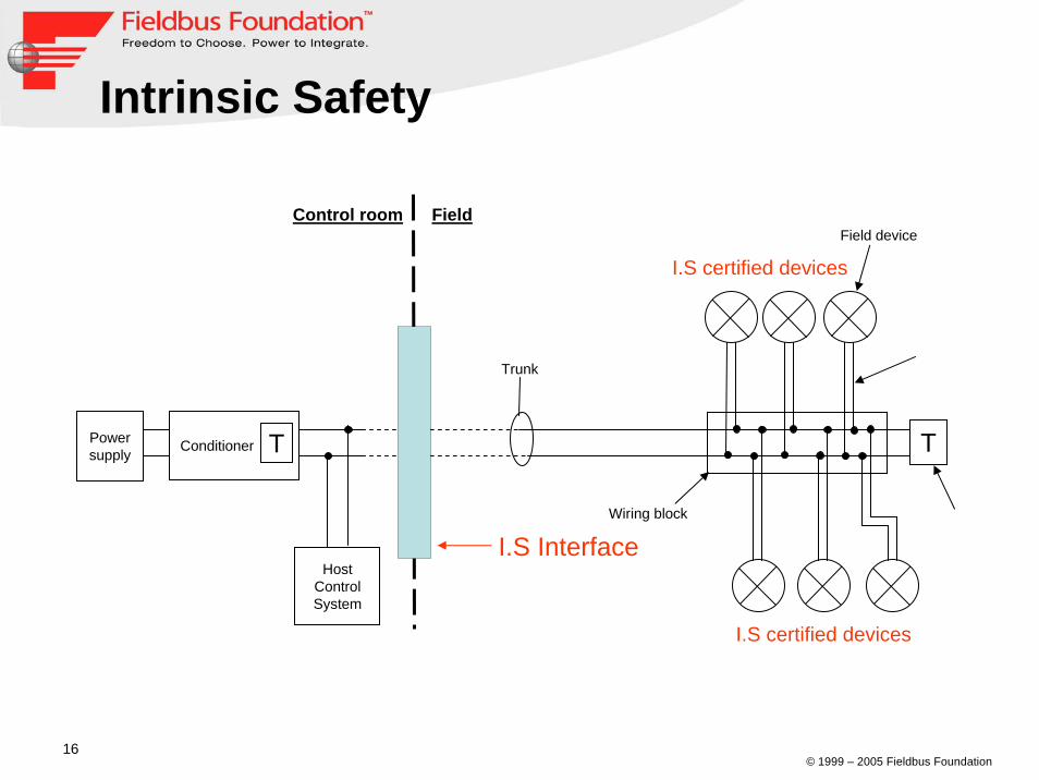
Intrinsic Safety
Control room Field
T
Trunk
Wiring block
Field device
Powersupply
Host Control System
Conditioner T
I.S Interface
I.S certified devices
I.S certified devices
© 1999 – 2005 Fieldbus Foundation17
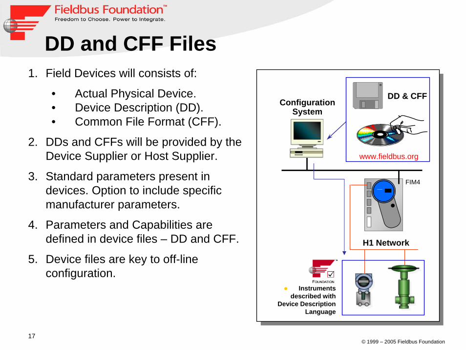
DD and CFF Files
ConfigurationSystem
H1 Network
1. Field Devices will consists of:
• Actual Physical Device.• Device Description (DD).• Common File Format (CFF).
2. DDs and CFFs will be provided by theDevice Supplier or Host Supplier.
3. Standard parameters present in devices. Option to include specific manufacturer parameters.
4. Parameters and Capabilities are defined in device files – DD and CFF.
5. Device files are key to off-lineconfiguration.
DD & CFF
Instruments described with
Device Description Language
www.fieldbus.org
FIM4

© 1999 – 2005 Fieldbus Foundation18
DD and CFF Files1. Device Descriptor (DD) File allow operation of devices from different
suppliers on the same fieldbus with single host system.
2. Common File Format (CFF) is a file which describes the functions and capabilities of a field device. The CFF file is used in conjunction with the Device Descriptor file to enable a host system to configure the system off-line.
3. CFF files are standard ASCII text file.

© 1999 – 2005 Fieldbus Foundation19
Typical Fieldbus Installation
PC Power supply
T
PC Power supply
T
24V DC Bulk power
• An example of the Chicken foot (tree) topology.
• Redundant, isolated power conditioning defined by FF-831, Fieldbus PST Specs.
• Typically 10-12 bus-powered fieldbus devices per segment.
• Spur short-circuit protection.
• Up to 1900 meters.• Maximum of 9500 meters
via repeaters.
TrunkSpur
Segment
Field Devices
Control System (Host)Fieldbus Interface Module
FFFF--831831

© 1999 – 2005 Fieldbus Foundation20
Fieldbus Component
WorkstationWorkstation
TransmittersTransmitters
HMIHMI
TerminatorTerminator
Power SupplyPower Supply
Junction BoxJunction Box
H1 Bus Wire (Spurs)H1 Bus Wire (Spurs)
HSE (FTE) CableHSE (FTE) CableConditionerConditioner
ActuatorActuator
Fieldbus Interface ModuleFieldbus Interface Module
TerminatorTerminator
H1 Bus (Trunk)H1 Bus (Trunk) Hazardous Area (Field)
Safe Area (Host)
FOUNDATIONFOUNDATION™™ Fieldbus SystemFieldbus System

© 1999 – 2005 Fieldbus Foundation21
H1 Fieldbus ModelFOUNDATION fieldbus H1 technology consists of:
• The Physical Layer.• The Communication Stack.• The User Application Layer.
The Open Systems Interconnect (OSI) layered communication model is used to model these components.
• Physical Layer is OSI layer 1.• Data Link Layer is OSI layer 2.• FMS is OSI layer 7.• Communication stack is comprised
of layer 2 and layer 7.• Fieldbus does not use OSI layer
3, 4, 5 and 6. • FAS maps the FMS into DLL.

© 1999 – 2005 Fieldbus Foundation22
1. The Physical Layer receives messages from the communication stack and converts the messages into physical signals on the fieldbus transmission medium and vice versa.
2. Conversion includes adding and removing preambles, start delimiters and end delimiters.
H1 Fieldbus Model

© 1999 – 2005 Fieldbus Foundation23
1. The Communication Stack comprises of Layer 2 and 7.
2. Layer 2, the Data Link Layer (DLL) controls transmission of messages onto the fieldbus, through a deterministic centralized bus scheduler call the Link Active Scheduler (LAS).
3. FAS uses the scheduled and unscheduled features of the DLL toprovide a service for the FMS.
3. FMS services allow user applicationsto send messages to each otheracross the fieldbus using a standardset of messages.
H1 Fieldbus Model

© 1999 – 2005 Fieldbus Foundation24
User Application - Blocks1. The Fieldbus Foundation has defined a standard User Application Layer
based on “Blocks”.
2. Blocks are representations of different types of application functions.
3. The types of blocks used in a User Application are described as:
• Resource Block, • Transducer Block,• Function Blocks.
4. Devices are configured usingResource Block and Transducer Block.
5. The Control Strategy is built usingFunction Blocks.
© 1999 – 2005 Fieldbus Foundation25
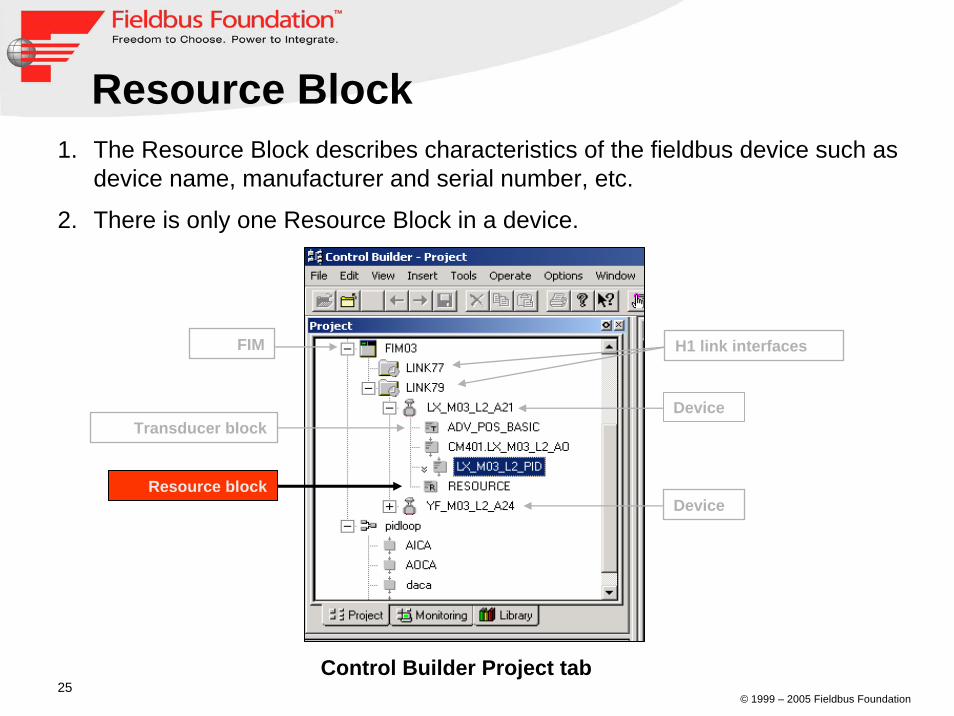
Resource Block1. The Resource Block describes characteristics of the fieldbus device such as
device name, manufacturer and serial number, etc.
2. There is only one Resource Block in a device.
Control Builder Project tab
FIM H1 link interfaces
Device
DeviceResource block
Transducer block

© 1999 – 2005 Fieldbus Foundation26
Transducer Block1. Transducer Blocks are used to configure devices.
2. Transducer Blocks are required to Read sensors value and command output value.
Control Builder Project tab
FIM H1 link interfaces
Device
DeviceResource block
Transducer block

© 1999 – 2005 Fieldbus Foundation27
Function Blocks1. The Control System Strategy is built using Function Blocks. Input and output
parameters of Function Blocks can be linked over the fieldbus.
2. The execution of each Function Blocks is precisely scheduled and there can be many function blocks in a single user application.
AI Block PID Block
AO Block

© 1999 – 2005 Fieldbus Foundation28
Standard Function Blocks
Function BlocksFunction Blocks AbbreviationAbbreviation Class TypeClass TypeAnalog Input AI InputAnalog Output AO OutputBias/Gain BG ControlControl Selector CS ControlDiscrete Input DI InputDiscrete Output DO OutputManual Loader ML ControlProportional/Derivative PD ControlProportional/Integral/Derivative PID ControlRatio RA Control
1. The Fieldbus Foundation has defined 10 Standard Function Blocks for Basic Control.
© 1999 – 2005 Fieldbus Foundation29
Standard Function Blocks
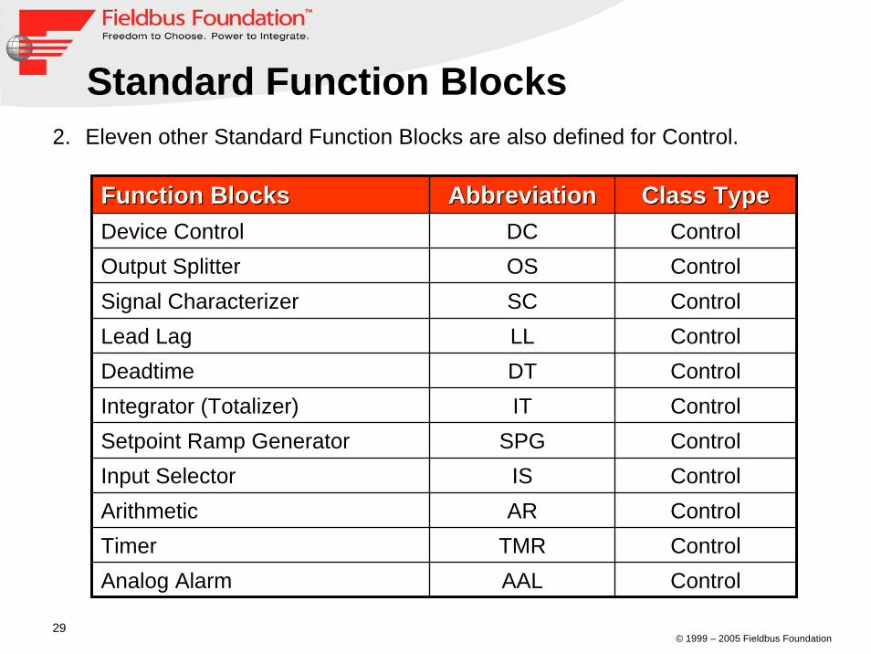
Function BlocksFunction Blocks AbbreviationAbbreviation Class TypeClass Type
Timer TMR Control
Device Control DC ControlOutput Splitter OS ControlSignal Characterizer SC ControlLead Lag LL ControlDeadtime DT ControlIntegrator (Totalizer) IT ControlSetpoint Ramp Generator SPG ControlInput Selector IS ControlArithmetic AR Control
Analog Alarm AAL Control
2. Eleven other Standard Function Blocks are also defined for Control.
© 1999 – 2005 Fieldbus Foundation30
Standard Function Blocks
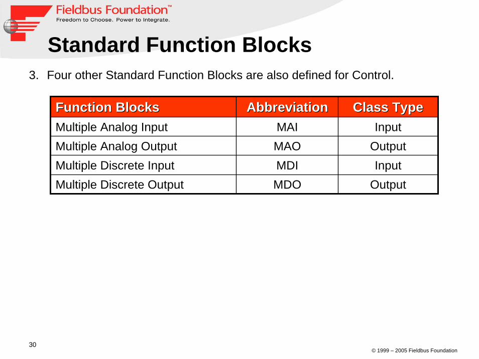
Function BlocksFunction Blocks AbbreviationAbbreviation Class TypeClass TypeMultiple Analog Input MAI InputMultiple Analog Output MAO OutputMultiple Discrete Input MDI InputMultiple Discrete Output MDO Output
3. Four other Standard Function Blocks are also defined for Control.
© 1999 – 2005 Fieldbus Foundation31
AI Block PID Block
AO Block
HSE (FTE)
FIM4
PIDAI
AO
H1 Fieldbus
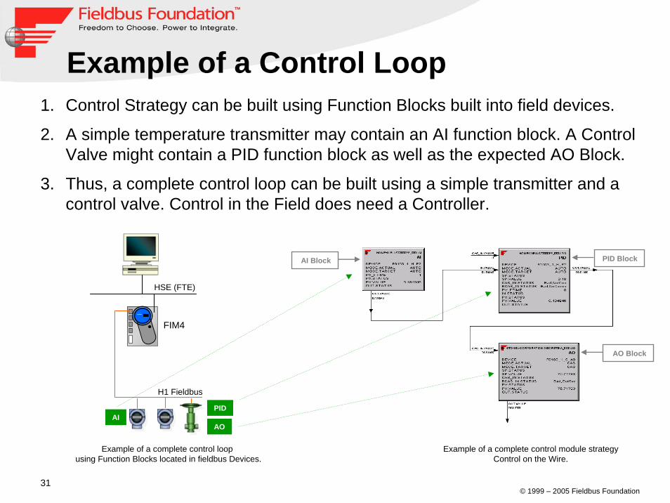
1. Control Strategy can be built using Function Blocks built into field devices.
2. A simple temperature transmitter may contain an AI function block. A Control Valve might contain a PID function block as well as the expected AO Block.
3. Thus, a complete control loop can be built using a simple transmitter and a control valve. Control in the Field does need a Controller.
Example of a complete control loop using Function Blocks located in fieldbus Devices.
Example of a complete control module strategyControl on the Wire.
Example of a Control Loop
© 1999 – 2005 Fieldbus Foundation32
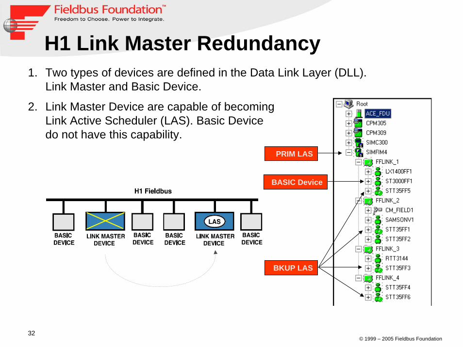
H1 Link Master Redundancy1. Two types of devices are defined in the Data Link Layer (DLL).
Link Master and Basic Device.
2. Link Master Device are capable of becoming Link Active Scheduler (LAS). Basic Device do not have this capability.
BKUP LAS
PRIM LAS
BASIC Device
© 1999 – 2005 Fieldbus Foundation33
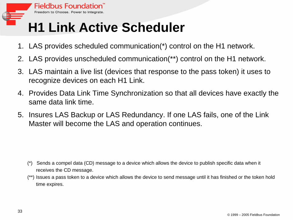
H1 Link Active Scheduler1. LAS provides scheduled communication(*) control on the H1 network.
2. LAS provides unscheduled communication(**) control on the H1 network.
3. LAS maintain a live list (devices that response to the pass token) it uses to recognize devices on each H1 Link.
4. Provides Data Link Time Synchronization so that all devices have exactly the same data link time.
5. Insures LAS Backup or LAS Redundancy. If one LAS fails, one of the Link Master will become the LAS and operation continues.
(*) Sends a compel data (CD) message to a device which allows the device to publish specific data when it receives the CD message.
(**) Issues a pass token to a device which allows the device to send message until it has finished or the token hold time expires.
© 1999 – 2005 Fieldbus Foundation34
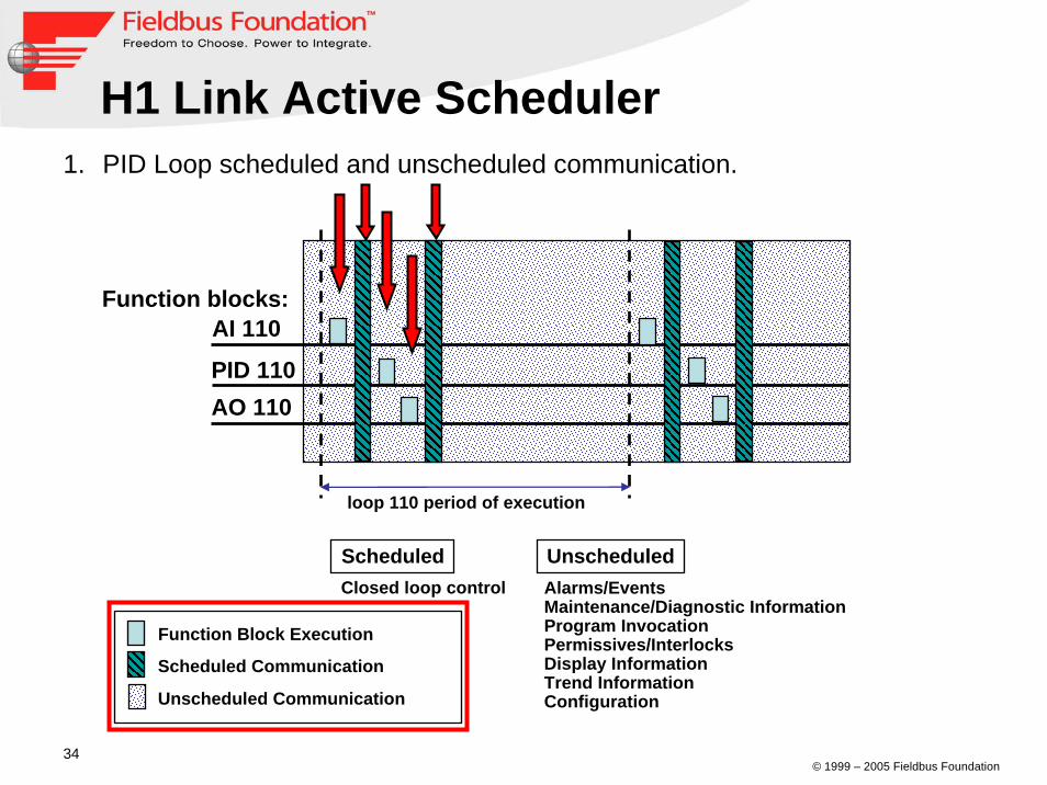
H1 Link Active Scheduler
AI 110
Scheduled UnscheduledClosed loop control Alarms/Events
Maintenance/Diagnostic InformationProgram InvocationPermissives/InterlocksDisplay InformationTrend InformationConfiguration
loop 110 period of execution
PID 110AO 110
Function Block Execution
Scheduled Communication
Unscheduled Communication
Function blocks:
1. PID Loop scheduled and unscheduled communication.

© 1999 – 2005 Fieldbus Foundation35
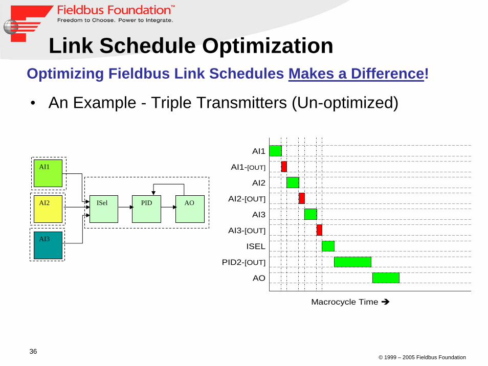
Link Schedule Optimization1. Makes effective use of Fieldbus bandwidth.
2. Important for Control on the Wire.
3. Allow for better time management on the Link.
4. Link Schedule Optimization provides a quantum improvement in theefficiency of Fieldbus Link bandwidth use.
© 1999 – 2005 Fieldbus Foundation36
• An Example - Triple Transmitters (Un-optimized)
Optimizing Fieldbus Link Schedules Makes a Difference!
AI1
AI1-[OUT]
AI2
AI2-[OUT]
AI3
Macrocycle Time
AI3-[OUT]
ISEL
PID2-[OUT]
AO
AI1
AI2
AI3
ISel PID AO
Link Schedule Optimization
© 1999 – 2005 Fieldbus Foundation37
AI1
AI2
AI3
ISel PID AOAI1
AI1-[OUT]
AI2
AI2-[OUT]
AI3
Macrocycle Time
AI3-[OUT]
ISEL
PID2-[OUT]
AO
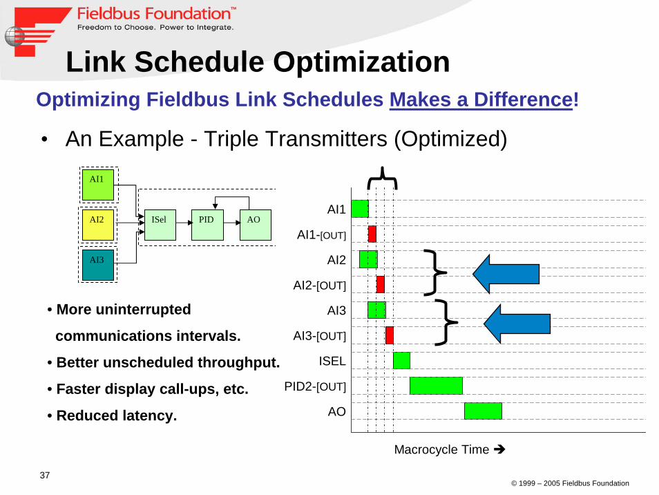
• More uninterrupted
communications intervals.
• Better unscheduled throughput.
• Faster display call-ups, etc.
• Reduced latency.
Link Schedule OptimizationOptimizing Fieldbus Link Schedules Makes a Difference!
• An Example - Triple Transmitters (Optimized)

© 1999 – 2005 Fieldbus Foundation38
DemostrationDemostration(5 to 10 minutes)(5 to 10 minutes)

© 1999 – 2005 Fieldbus Foundation39
www.fieldbus.org
Thank You


![Characterizing Test Methods and Emissions Reduction ...184-H1. 155-H1. 170-H1. 198-H1. 218-H1. 1. 10. 100. 1000. Axis Title Diameter [nm] A_0581_492_H1. A_0581_466_H1. A_0581_482_H1.](https://static.fdocuments.in/doc/165x107/5f74a0f484fbe405e9323ea1/characterizing-test-methods-and-emissions-reduction-184-h1-155-h1-170-h1.jpg)