H1 045/053 Tandem Axial Piston Pumps Technical Information ...
56
MAKING MODERN LIVING POSSIBLE Technical Information H1 Axial Piston Tandem Pumps Size 045/053 powersolutions.danfoss.com
Transcript of H1 045/053 Tandem Axial Piston Pumps Technical Information ...

MAKING MODERN LIVING POSSIBLE
Technical Information
H1 Axial Piston Tandem PumpsSize 045/053
powersolutions.danfoss.com

Revision history Table of revisions
Date Changed Rev
September 2014 MDC, CCO, and Swash Angle Sensor options added EA
Apr 2014 Converted to Danfoss layout - DITA CMS DA
Dec 2012 Various changes CA
Jul 2010 New EC directive BA
Jul 2009 First edition AA
Technical Information H1 Axial Piston Tandem Pumps, Size 045/053
2 11063345 • Rev EA • September 2014
Technical specificationsH1P general specifications Tandem.......................................................................................................................................... 5Technical data H1T 045/053 Tandem........................................................................................................................................5Operating parameters H1T 045/053 Tandem........................................................................................................................ 6Fluid specifications H1P ................................................................................................................................................................ 6External radial shaft loads H1T 045/053 Tandem................................................................................................................. 7
External radial shaft loads........................................................................................................................................................ 7Bearing life H1T 045/053 Tandem.............................................................................................................................................. 7Mounting flange loads H1T 045/053 Tandem....................................................................................................................... 8
H1 tandem pump front flange load..................................................................................................................................... 8Mounting flange load external charge pump.................................................................................................................. 8
Case drain............................................................................................................................................................................................9Charge pump..................................................................................................................................................................................... 9
Charge pump sizing/selection............................................................................................................................................... 9Integrated charge pump option...................................................................................................................................... 9Charge pump flow and power curves, 24 cm³............................................................................................................ 9
Model code H1T 045/053 Tandem
Control optionsElectrical Displacement Control (EDC), options: A2 (12 V) / A3 (24 V)........................................................................ 15
EDC control signal requirements........................................................................................................................................ 15Connector.............................................................................................................................................................................. 16
EDC solenoid data, 045/53 Tandem...................................................................................................................................16Control response.......................................................................................................................................................................16Response time, EDC 045/053............................................................................................................................................... 17
Manual Displacement Control (MDC) ....................................................................................................................................17MDC principle............................................................................................................................................................................ 17MDC general information......................................................................................................................................................18Shaft rotation MDC.................................................................................................................................................................. 19Control response.......................................................................................................................................................................19Response time, MDC 045/053..............................................................................................................................................19Neutral Start Switch (NSS)..................................................................................................................................................... 20
Connector.............................................................................................................................................................................. 20Case gauge port M14.............................................................................................................................................................. 21Lever..............................................................................................................................................................................................21
Forward-Neutral-Reverse (FNR), options: A9 (12 V) / B1 (24 V) Tandem....................................................................22Connector....................................................................................................................................................................................22Control response.......................................................................................................................................................................23Response time, FNR 045/053................................................................................................................................................23
Non Feedback Proportional Electric Control (NFPE), options: A8 (12 V) / B8 (24 V)...............................................24Control signal requirements, NFPE 045/053 Tandem................................................................................................. 24
Connector.............................................................................................................................................................................. 25Control response.......................................................................................................................................................................25Response time, NFPE 045/053............................................................................................................................................. 26
Manual Over Ride (MOR)............................................................................................................................................................. 27Swash Angle Sensor......................................................................................................................................................................27
Swash Angle Sensor parameters.........................................................................................................................................28Swash Angle Sensor connector...........................................................................................................................................28Interface with ECU....................................................................................................................................................................29
Fault codes and diagnostics............................................................................................................................................29Control-Cut-Off valve (CCO) for tandem pump.................................................................................................................. 30
Connector....................................................................................................................................................................................31Displacement limiter.....................................................................................................................................................................32
Displacement change (approximately) H1P 045/053 Single....................................................................................32
DimensionsPorts description H1P 045/053 Tandem................................................................................................................................33Dimensions H1T 045/053 Tandem.......................................................................................................................................... 35H1T input shaft, option G1 (SAE B, 14 teeth)........................................................................................................................38H1T input shaft, option G5 (SAE B-B, 15 teeth)................................................................................................................... 39
Technical Information H1 Axial Piston Tandem Pumps, Size 045/053
Contents
11063345 • Rev EA • September 2014 3

H1T input shaft, option F2, Code 25-3....................................................................................................................................40Tapered shaft customer acknowledgement...................................................................................................................40
External charge pump mounting options ........................................................................................................................... 41Auxiliary mounting pads without charge pump ...............................................................................................................42
H1T Auxiliary mounting, option H2 (SAE A, 9 teeth)....................................................................................................42H1T Auxiliary mounting, option H1 (SAE A, 11 teeth) ................................................................................................43H1T Auxiliary mounting, option H3 (SAE B, 13 teeth)................................................................................................. 44H1T Auxiliary mounting, option H5 (SAE B-B, 15 teeth)............................................................................................. 45
Auxiliary mounting pads with external charge pump......................................................................................................46Option T2 (SAE A, 9 teeth) .................................................................................................................................................... 46Option T1 (SAE A, 11 teeth) ..................................................................................................................................................47Option T3 (SAE B, 13 teeth) .................................................................................................................................................. 48
Electric Displacement Control (EDC), option A2 (12V) / A3 (24V) H1T 045/053...................................................... 49Electric Displacement Control (EDC) with MOR, option A4 (12 V) / A5 (24 V) H1T 045/053............................... 49Manual Displacement Control (MDC), option M1, H1T 045/053.................................................................................. 50Manual Displacement Control (MDC) with NSS, option M2, H1T 045/053............................................................... 51Manual Displacement Control (MDC) with NSS, option 09, H1T 045/053.................................................................52Forward-Neutral-Reverse (FNR) with MOR, option A9 (12 V) B1 (24 V), H1T 045/053...........................................53Non Feedback Proportional Electric Control (NFPE) with MOR, option A8 (12 V) B8 (24V) H1T 045/053......53Center section coupling, torque rating..................................................................................................................................54Control Cut Off (CCO) H1T 045/053.........................................................................................................................................55H1T displacement limiter, 045/053 Tandem, option B.....................................................................................................55
Technical Information H1 Axial Piston Tandem Pumps, Size 045/053
Contents
4 11063345 • Rev EA • September 2014

For definitions of the following specifications, see Basic Information 11062168, Operating parameters.
H1P general specifications Tandem
Design Axial piston pump of cradle swashplate design with variable displacement
Direction of rotation Clockwise, counterclockwise
Pipe connections Main pressure ports: SAE straight thread O-ring bossRemaining ports: SAE straight thread O-ring boss
Recommended installationposition
Pump installation position is discretionary, however the recommended control position is on the top or at the side,with the top position preferred. If the pump is installed with the control at the bottom, flushing flow must beprovided through port M14 located on the EDC and FNR control. Vertical input shaft installation is acceptable.The housing must always be filled with hydraulic fluid.Recommended mounting for a multiple pump stack is to arrange the highest power flow towards the input source.Consult Danfoss for nonconformance to these guidelines.
Auxiliary cavity pressure Will be inlet pressure with the charge pump option. For reference see operating parameters on next page. Will becase pressure with external charge supply. Please verify mating pump shaft seal capability.
Technical data H1T 045/053 Tandem
Feature Size 045 Size 053
Displacement 45.0 cm3
[2.75 in3]53.8 cm3
[3.28 in3]
Flow at rated (continuous) speed* 153 l/min[40 US gal/min]
183 l/min[48 US gal/min]
Torque at maximum displacement(theoretical)
0.8 N•m/bar[488 lbf•in/1000 psi]
0.9 N•m/bar[549 lbf•in/1000 psi]
Mass moment of inertia of rotatingcomponents
0.0078 kg•m2
[0.00575 slug•ft2]0.0077 kg•m2
[0.00568 slug•ft2]
Mass [weight] dry 65 kg [143 lb](without charge pump or auxiliary mounting flange)
Oil volume 2.3 l [0.61 US gal]
Mounting flange ISO 3019-1 flange 101-2 (SAE B), Special bolt diameter
Input shaft outer diameter,splines and tapered shafts
ISO 3019-1, outer Ø25 mm - 4 (SAE B-B, 15 teeth)ISO 3019-1, outer Ø32 mm - 4 (SAE-B, 14 teeth)Conical keyed shaft end similar to ISO 3019-1 code 25-3, taper 1:8
Auxiliary mounting flangewith metric fasteners,Shaft outer diameter and splines
ISO 3019-1, flange 82 - 2, outer Ø16 mm - 4 (SAE A, 9 teeth)ISO 3019-1, flange 82 - 2, outer Ø19 mm - 4 (SAE A, 11 teeth)ISO 3019-1, flange 101 - 2, outer Ø22 mm - 4 (SAE B, 13 teeth)ISO 3019-1, flange 101 - 2, outer Ø25 mm - 4 (SAE B-B, 15 teeth)**
Charge inlet port Port ISO 11926-1 – 1 7∕8 -14 (SAE O-ring boss)
Charge pump option Inlet port: ISO 11926-1 – 1 5∕8 -12 (SAE O-ring boss)Outlet port: ISO 11926-1 – 1 1∕16 -12 (SAE O-ring boss)
Main port configuration ISO 11926-1 – 1 5∕16 -12 (SAE O-ring boss)
Case drain port L3(use for cooling purposes)
Port ISO 11926-1 – 1 1∕16 -12 (SAE O-ring boss)
Other ports SAE O-ring boss
Customer interface threads Metric fasteners
* Applies for each rotating group** Not available with the tandem charge pump option
Technical Information H1 Axial Piston Tandem Pumps, Size 045/053
Technical specifications
11063345 • Rev EA • September 2014 5
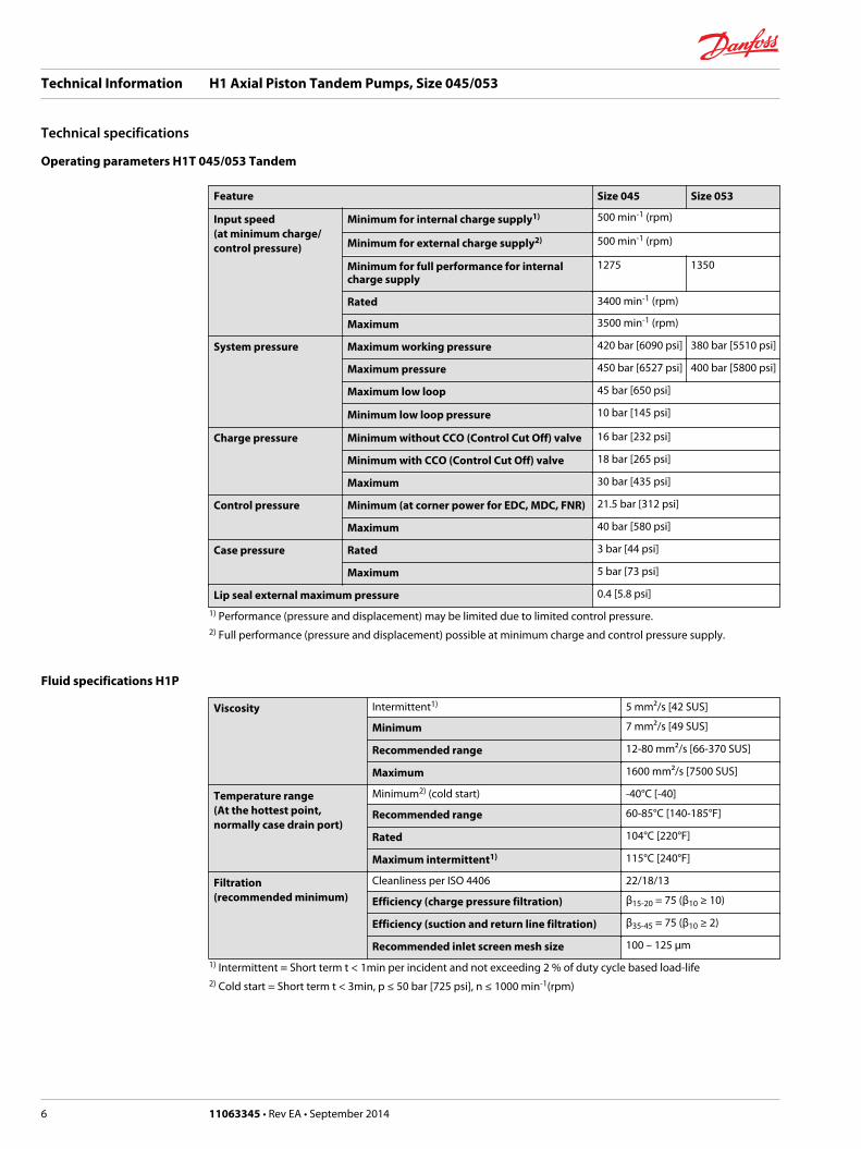
Operating parameters H1T 045/053 Tandem
Feature Size 045 Size 053
Input speed(at minimum charge/control pressure)
Minimum for internal charge supply1) 500 min-1 (rpm)
Minimum for external charge supply2) 500 min-1 (rpm)
Minimum for full performance for internalcharge supply
1275 1350
Rated 3400 min-1 (rpm)
Maximum 3500 min-1 (rpm)
System pressure Maximum working pressure 420 bar [6090 psi] 380 bar [5510 psi]
Maximum pressure 450 bar [6527 psi] 400 bar [5800 psi]
Maximum low loop 45 bar [650 psi]
Minimum low loop pressure 10 bar [145 psi]
Charge pressure Minimum without CCO (Control Cut Off) valve 16 bar [232 psi]
Minimum with CCO (Control Cut Off) valve 18 bar [265 psi]
Maximum 30 bar [435 psi]
Control pressure Minimum (at corner power for EDC, MDC, FNR) 21.5 bar [312 psi]
Maximum 40 bar [580 psi]
Case pressure Rated 3 bar [44 psi]
Maximum 5 bar [73 psi]
Lip seal external maximum pressure 0.4 [5.8 psi]
1) Performance (pressure and displacement) may be limited due to limited control pressure.2) Full performance (pressure and displacement) possible at minimum charge and control pressure supply.
Fluid specifications H1P
Viscosity Intermittent1) 5 mm²/s [42 SUS]
Minimum 7 mm²/s [49 SUS]
Recommended range 12-80 mm²/s [66-370 SUS]
Maximum 1600 mm²/s [7500 SUS]
Temperature range(At the hottest point,normally case drain port)
Minimum2) (cold start) -40°C [-40]
Recommended range 60-85°C [140-185°F]
Rated 104°C [220°F]
Maximum intermittent1) 115°C [240°F]
Filtration(recommended minimum)
Cleanliness per ISO 4406 22/18/13
Efficiency (charge pressure filtration) β15-20 = 75 (β10 ≥ 10)
Efficiency (suction and return line filtration) β35-45 = 75 (β10 ≥ 2)
Recommended inlet screen mesh size 100 – 125 µm
1) Intermittent = Short term t < 1min per incident and not exceeding 2 % of duty cycle based load-life2) Cold start = Short term t < 3min, p ≤ 50 bar [725 psi], n ≤ 1000 min-1(rpm)
Technical Information H1 Axial Piston Tandem Pumps, Size 045/053
Technical specifications
6 11063345 • Rev EA • September 2014

External radial shaft loads H1T 045/053 Tandem
External radial shaft loads
H1 pumps are designed with bearings that can accept some external radial loads. The external radialshaft load limits are a function of the load position and orientation, and the operating conditions of theunit. External radial shaft loads impact lifetime. For lifetime calculations please contact Danfossrepresentative.
The maximum allowable radial load (Re) is based on the maximum external moment (Me) and thedistance (L) from the mounting flange to the load.
It may be determined using the following formula: Re = Me
L
Radial load position
P003 303E
L
Re
Me
270° Re
180° Re
90° Re
0° Re
CCWRotation
CWRotation
Me = shaft momentL = flange distanceRe = external force to the shaft
Thrust loads should be avoided. Contact factory in the event thrust loads are anticipated.
Bearing life H1T 045/053 Tandem
Maximum external shaft moment based on shaft deflection (both sizes 045/053):
Me = TBD N•m [TBD lbf•in]
All external shaft loads affect bearing life. In applications with external shaft loads, minimize the impactby positioning the load at 0° or 180° as shown in the figure.
Danfoss recommends clamp-type couplings for applications with radial shaft loads.
Contact your Danfoss representative for an evaluation of unit bearing life if you have continuouslyapplied external loads exceeding 25 % of the maximum allowable radial load (Re) or the pumpswashplate is positioned on one side of center all or most of the time.
Technical Information H1 Axial Piston Tandem Pumps, Size 045/053
Technical specifications
11063345 • Rev EA • September 2014 7

Mounting flange loads H1T 045/053 Tandem
H1 tandem pump front flange load
Mounting flange loads H1T 045/053, Controls on top
P003 367
MR
MS
The moments shown below apply for the control orientation on top or side.
Mounting flange loads, Control on top
P003 366a
Control on top
Rated moment:
MR = 2020 N•m [17 880 lbf•in]
Shock load moment:
MS = 4110 N•m [36 380 lbf•in]
Mounting flange loads, Control on side
P003 366b
Control on side
Rated moment:
MR = 1300 N•m [11 510 lbf•in]
Shock load moment:
MS = 2930 N•m [25 935 lbf•in]
For calculation details refer to H1 Axial Piston Pumps, Basic Information 11062168, chapter Mountingflange loads.
Mounting flange load external charge pump
Mounting flange load external charge pump
P003 552
MR
MS
Rated moment:
MR = 520 N•m [4600 lbf•in]
Shock load moment:
MS = 1300 N•m [11 500 lbf•in]
For calculation details refer to H1 Axial Piston Pumps, Basic Information 11062168, chapter Mountingflange loads.
Technical Information H1 Axial Piston Tandem Pumps, Size 045/053
Technical specifications
8 11063345 • Rev EA • September 2014

Case drain
The tandem housings are connected through the center section via a drilled hole. The charge relief valvedischarges oil into the front housing. In order to provide positive flow through both housings, use of therear housing case drain is required. The front housing case pressure ports should only be used if thepump is used as a common drain manifold for the vehicle where external drain flow is brought into therear housing and discharged out the front.
The allowable case pressures must be met accordingly.
Charge pump
Charge pump sizing/selection
In most applications a general guideline is that the charge pump displacement should be at least 10 % ofthe total displacement of all components in the system. Unusual application conditions may require amore detailed review of charge flow requirements. Please refer to Selection of Drive line Components,BLN-9885 for a detailed procedure.
System features and conditions which may invalidate the 10 % guideline include (but are not limited to):• Continuous operation at low input speeds (< 1500 min-1 (rpm))
• High shock loading and/or long loop lines
• High flushing flow requirements
• Multiple low speed high torque motors
• High input shaft speeds
Contact your Danfoss representative for application assistance if your application includes any of theseconditions.
Integrated charge pump option
The tandem pumps are available with an optional gerotor module bolted onto the back of the rear pumpas show in the figures below. The charge pump is available with SAE A or B auxiliary pads or a no-pad option. The orientation of the charge pump can be specified in oneof the configurations shown.
Charge pump flow and power curves, 24 cm³
Charge pressure: 20 bar [290 psi] / Viscosity: 11 mm²/s [63 SUS] / Temperature: 80°C [176°F]
Charge pump power requirements
0
1
2
3
4
5
5000 1000 1500 2000 2500 3000 35000
1.0
4.0
2.0
3.0
HP
Pow
er (k
W) 24 cm
3 [1.47 in3 /rev]
P003 539ESpeed min-1(rpm)
Technical Information H1 Axial Piston Tandem Pumps, Size 045/053
Technical specifications
11063345 • Rev EA • September 2014 9

Charge pump flow
01020304050607080
0 500 1000 1500 2000 2500 3000 3500
P003 538ESpeed min-1(rpm)
US
gal/m
in
l/min
13
6
9
12
15
18
21
24 cm3 [1.47 in
3 /rev]
Technical Information H1 Axial Piston Tandem Pumps, Size 045/053
Technical specifications
10 11063345 • Rev EA • September 2014

A
A B D EF G H J K M N P R S T V W X YH1 T N
CN F
Displacement (front pump, second pump see “C”)
045 45 cm3 [2.75 in3]
053 53.8 cm3 [3.28 in3]
A – Rotation
L Left hand (counter clockwise)
R Right hand (clockwise)
B – Product version
A Revision code
C – Second pump size
N Frame size of rear stage equal front stage (default)
D – Control
A2 Electric Displacement Control (EDC) 12V, Deutsch connector
A3 Electric Displacement Control (EDC) 24V, Deutsch connector
A4 Electric Displacement Control (EDC) 12V, Deutsch connector, Manual override
A5 Electric Displacement Control (EDC) 24V, Deutsch connector, Manual override
A9 Forward-Neutral-Reverse (FNR) 12V, Deutsch connector, Manual override
B1 Forward-Neutral-Reverse (FNR) 24V, Deutsch connector, Manual override
A8 Non Feedback Proportional Electric (NFPE) 12V, Deutsch connector, Manual override1)
B8 Non Feedback Proportional Electric (NFPE) 24V, Deutsch connector, Manual override 1)
B5 Non Feedback Proportional Electric (NFPE) 12V, Deutsch connector, Swash Plate Angle Sensor 1)
B9 Non Feedback Proportional Electric (NFPE) 24V, Deutsch connector, Swash Plate Angle Sensor 1)
M1 Manual Displacement Control (MDC)2)
M2 Manual Displacement Control (MDC) with Neutral Start Switch, Deutsch Connector 2)
1) Align with options: F: Displacement Limiters and W: Special Hardware.2) Align with option: F: Orifices.
Technical Information H1 Axial Piston Tandem Pumps, Size 045/053
Model code H1T 045/053 Tandem
11063345 • Rev EA • September 2014 11

A
A B D EF G H J K M N P R S T V W X YH1 T N
CN F
F – Orifices (mm)
Code Tank (A+B) P A / B
C1 – – 0.8
C2 – – 1.3
D5* 0.6 0.6 0.8
C8* 0.6 0.8 –
C9* 0.6 1 –
D1* 0.8 1 –
D2* 0.8 1.3 –
D3* 1 1.3 –
D4* 1 1.3 1.3
C6* 1 – –
C7* 1.3 – –
C3 No orifice, Not recommended for mobile applications
* to be used with MDC controls only.
E – Displacement limiters
N None
G – Endcap options
E7 Tandem same-sided SAE O-ring boss ports, (HPRV only) Standard
D1 Tandem same-sided SAE O-ring boss ports with Control Cut Off (HPRV only), 12 V
F7 Tandem same-sided SAE O-ring boss ports with Control Cut Off (HPRV only), 24 V
H – Mounting
F ISO 3019-1, flange 101-2 (SAE B)
J – Input shaft
G1 ISO 3019-1, outer Ø32 mm - 4 (SAE C, 14 teeth splined shaft 12/24 pitch)
G5 ISO 3019-1, outer Ø25 mm - 4 (SAE B, 15 teeth splined shaft 16/32 pitch)
F2 Conical keyed shaft end similar to ISO 3019-1 code 25-3, taper 1:8 (key not supplied with pump)
Technical Information H1 Axial Piston Tandem Pumps, Size 045/053
Model code H1T 045/053 Tandem
12 11063345 • Rev EA • September 2014

A
A B D EF G H J K M N P R S T V W X YH1 T N
CN F
K – Auxiliary mounting pad (align with option S: Charge pump and option Y: Special settings)
Without charge pump
NN None
H2 ISO 3019-1, flange 82 - 2, outer Ø16 mm - 4 (SAE A, 9 teeth 16/32 coupling)
Shipping coverH1 ISO 3019-1, flange 82 - 2, outer Ø19 mm - 4 (SAE A, 11 teeth 16/32 coupling)
H3 ISO 3019-1, flange 101 - 2, outer Ø22 mm - 4 (SAE B, 13 teeth 16/32 coupling)
H5 ISO 3019-1, flange 101 - 2, outer Ø25 mm - 4 (SAE B-B, 15 teeth 16/32 coupling)
With charge pump
TN No auxiliary mounting pad
T2 ISO 3019-1, flange 82 - 2, outer Ø16 mm - 4 (SAE A, 9 teeth 16/32 coupling)
Shipping coverT1 ISO 3019-1, flange 82 - 2, outer Ø19 mm - 4 (SAE A, 11 teeth 16/32 coupling)
T3 ISO 3019-1, flange 101 - 2, outer Ø22 mm - 4 (SAE B, 13 teeth 16/32 coupling)
M – High pressure relief valve setting, NO bypass, side “A” (front pump) N – High pressure relief valve setting, NO bypass side “B” (front pump) P – High pressure relief valve setting, NO bypass, side “C” (rear pump) R – High pressure relief valve setting, NO bypass, side “D” (rear pump)
Code Pressure setting*
18 180 bar [2610 psi]
20 200 bar [2900 psi]
23 230 bar [3336 psi]
25 250 bar [3630 psi]
28 280 bar [4061 psi]
30 300 bar [4350 psi]
33 330 bar [4786 psi]
35 350 bar [5080 psi]
38 380 bar [5510 psi]
40 400 bar [5800 psi] (45 cm3 only)
42 420 bar [6090 psi] (45 cm3 only)
* Use the selection for ports “A” , “B” , “C” and “D”.
S – Charge pump
M 24 cm³/rev [1.46 in³/rev]
N No charge pump, external charge supply*
* Align with options: E and T
T – Filtration
P Remote full charge flow filtration
Technical Information H1 Axial Piston Tandem Pumps, Size 045/053
Model code H1T 045/053 Tandem
11063345 • Rev EA • September 2014 13

A
A B D EF G H J K M N P R S T V W X YH1 T N N F
C
V - Charge pressure relief setting
BK 20 bar [290 psi]
BD 24 bar [348 psi]
CK 30 bar [435 psi]
W – Special hardware features
PN None
P1 NFPE valve plate (align with options: D: Control selection and E: Displacement limiters)
X – Paint and nametag
NNN Black paint and Danfoss nametag
Y – Special settings (align with option K: Auxiliary mounting pad and option S: Charge pump)
NNN None
S01 Charge pump orientation at 0°
S02 Charge pump orientation at 180°
Technical Information H1 Axial Piston Tandem Pumps, Size 045/053
Model code H1T 045/053 Tandem
14 11063345 • Rev EA • September 2014
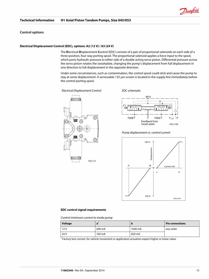
Electrical Displacement Control (EDC), options: A2 (12 V) / A3 (24 V)
The Electrical Displacement Control (EDC) consists of a pair of proportional solenoids on each side of athree-position, four-way porting spool. The proportional solenoid applies a force input to the spool,which ports hydraulic pressure to either side of a double acting servo piston. Differential pressure acrossthe servo piston rotates the swashplate, changing the pump‘s displacement from full displacement inone direction to full displacement in the opposite direction.
Under some circumstances, such as contamination, the control spool could stick and cause the pump tostay at some displacement. A serviceable 125 μm screen is located in the supply line immediately beforethe control porting spool.
Electrical Displacement Control
P003 191
EDC schematic
Feedback from Swash plate
PTF00B
M14
C1 C2
F00A
P003 478E
Pump displacement vs. control current
P003 479E
"0"-b -a
ba
100 %
100 %
Dis
plac
emen
t
Current mA
EDC control signal requirements
Control minimum current to stroke pump
Voltage a* b Pin connections
12 V 640 mA 1640 mA any order
24 V 330 mA 820 mA* Factory test current, for vehicle movement or application actuation expect higher or lower value.
Technical Information H1 Axial Piston Tandem Pumps, Size 045/053
Control options
11063345 • Rev EA • September 2014 15

Connector
1 2
P003 480
Connector ordering data
Description Quantity Ordering number
Mating connector 1 Deutsch® DT06-2S
Wedge lock 1 Deutsch® W2S
Socket contact (16 and 18 AWG) 2 Deutsch® 0462-201-16141
Danfoss mating connector kit 1 K29657
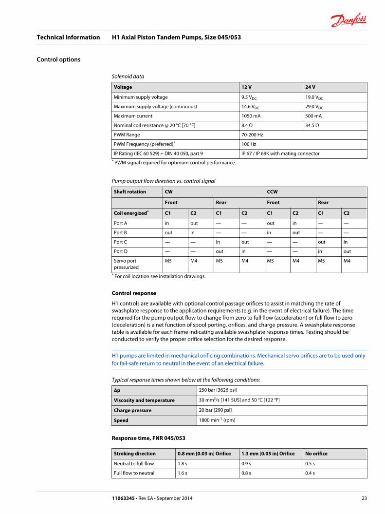
EDC solenoid data, 045/53 Tandem
Solenoid data
Description 12 V 24 V
Maximum current 1800 mA 920 mA
Nominal coil resistance @ 20 °C [68 °F] 3.66 Ω 14.20 Ω
@ 80 °C [176 °F] 4.52 Ω 17.52 Ω
Inductance 33 mH 140 mH
PWM Range 70-200 Hz
Frequency (preferred)* 100 Hz
IP Rating IEC 60 529 IP 67
DIN 40 050, part 9 IP 69K with mating connector
* PWM signal required for optimum control performance.
Pump output flow direction vs. control signal
Shaft rotation CW CCW
Front Rear Front Rear
Coil energized* C2 C1 C2 C1 C2 C1 C2 C1
Port A in out — — out in — —
Port B out in — — in out — —
Port C — — in out — — out in
Port D — — out in — — in out
Servo portpressurized
M5 M4 M5 M4 M5 M4 M5 M4
* For coil location see Installation drawings.
Control response
H1 controls are available with optional control passage orifices to assist in matching the rate ofswashplate response to the application requirements (e.g. in the event of electrical failure). The timerequired for the pump output flow to change from zero to full flow (acceleration) or full flow to zero(deceleration) is a net function of spool porting, orifices, and charge pressure. A swashplate responsetable is available for each frame indicating available swashplate response times. Testing should beconducted to verify the proper orifice selection for the desired response.
Technical Information H1 Axial Piston Tandem Pumps, Size 045/053
Control options
16 11063345 • Rev EA • September 2014

H1 pumps are limited in mechanical orificing combinations. Mechanical servo orifices are to be used onlyfor fail-safe return to neutral in the event of an electrical failure.
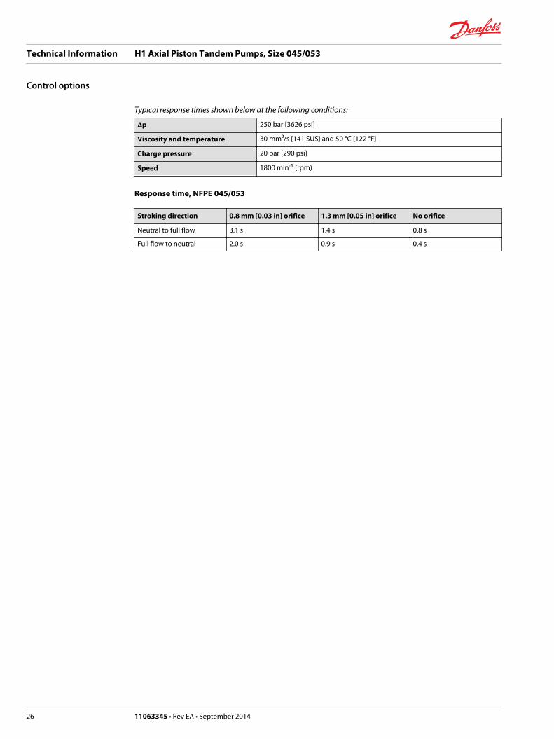
Typical response times shown below at the following conditions:
∆p 250 bar [3626 psi]
Viscosity and temperature 30 mm²/s [141 SUS] and 50 °C [122 °F]
Charge pressure 20 bar [290 psi]
Speed 1800 min-1 (rpm)
Response time, EDC 045/053
Stroking direction 0.8 mm [0.03 in] orifice 1.3 mm [0.05 in] orifice No orifice
Neutral to full flow 1.7 s 0.9 s 0.5 s
Full flow to neutral 1.1 s 0.6 s 0.3 s
Manual Displacement Control (MDC)
MDC principle
An MDC is a Manual proportional Displacement Control (MDC). The MDC consists of a handle on top of arotary input shaft. The shaft provides an eccentric connection to a feedback link. This link is connected onits one end with a porting spool. On its other end the link is connected the pumps swashplate.
This design provides a travel feedback without spring. When turning the shaft the spool moves thusproviding hydraulic pressure to either side of a double acting servo piston of the pump.
Differential pressure across the servo piston rotates the swash plate, changing the pump’s displacement.Simultaneously the swashplate movement is fed back to the control spool providing proportionalitybetween shaft rotation on the control and swashplate rotation.
The MDC changes the pump displacement between no flow and full flow into opposite directions. Undersome circumstances, such as contamination, the control spool could stick and cause the pump to stay atsome displacement.
A serviceable 125 μm screen is located in the supply line immediately before the control porting spool.
The MDC is sealed by means of a static O-ring between the actuation system and the control block. Itsshaft is sealed by means of a special O-ring which is applied for low friction. The special O-ring isprotected from dust, water and aggressive liquids or gases by means of a special lip seal.
Manual Displacement Control on H1 pump
P301 749
MDC schematic diagram
P005 701
M14
M5 M4 M3
Technical Information H1 Axial Piston Tandem Pumps, Size 045/053
Control options
11063345 • Rev EA • September 2014 17

Pump displacement vs. control lever rotation
"0"Lever rotation"A"
Dis
plac
emen
t
100 %
a
-a
100 %
"B"-b-d
b c
d
-c
P301 752
Where:
Deadband on B side – a = 3° ±1°
Maximum pump stroke – b = 30° +2/-1°
Required customer end stop – c = 36° ±3°
Internal end stop – d = 40°
MDC torque
Torque required to move handle to maximum displacement 1.4 N•m [12.39 lbf•in ]
Torque required to hold handle at given displacement 0.6 N•m [5.31 lbf•in]
Maximum allowable input torque 20 N•m [177 lbf•in]
Volumetric efficiencies of the system will have impacts on the start and end input commands.
MDC general information
In difference to other controls the MDC provides a mechanical deadband. This is required to overcomethe tolerances in the mechanical actuation.
The MDC contains an internal end stop to prevent over travel. The restoring moment is appropriate forturning the MDC input shaft back to neutral only. Any linkages or cables may prevent the MDC fromreturning to neutral.
The MDC is designed for a maximum case pressure of 5 bar and a rated case pressure of 3 bar. If the casepressure exceeds 5 bar there is a risk of an insufficient restoring moment. In addition a high case pressurecan cause the NSS to indicate that the control is not in neutral. High case pressure may cause excessivewear.
For the MDC with CCO option the brake port (X7) provides charge pressure when the coil is energized toactivate static function such as a brake release. The X7 port must not be used for any continuous oilconsumption.
Customers can apply their own handle design but they must care about a robust clamping connectionbetween their handle and the control shaft and avoid overload of the shaft.
Customers can connect two MDC’s on a tandem unit such way the actuation force will be transferredfrom the pilot control to the second control but the kinematic of the linkages must ensure that eithercontrol shaft is protected from torque overload.
To avoid an overload of the MDC customers must install any support to limit the setting range of theBowden cable.
C Caution
The internal spring force on the input shaft is not appropriate to return any customer connection linkageto neutral.
Technical Information H1 Axial Piston Tandem Pumps, Size 045/053
Control options
18 11063345 • Rev EA • September 2014

Shaft rotation MDC
Shaft rotation MDC
CCW
CW
P301 753
MDC shaft rotation data
Pump shaft rotation* Clock Wise (CW) Counter Clock Wise (CCW)
MDC shaft rotation CW CCW CW CCW
Port A in (low) out (high) out (high) in (low)
Port B out (high) in (low) in (low) out (high)
Servo port high pressure M5 M4 M5 M4* as seen from shaft side
Control response
H1 controls are available with optional control passage orifices to assist in matching the rate ofswashplate response to the application requirements (e.g. in the event of electrical failure). The timerequired for the pump output flow to change from zero to full flow (acceleration) or full flow to zero(deceleration) is a net function of spool porting, orifices, and charge pressure. A swashplate responsetable is available for each frame indicating available swashplate response times. Testing should beconducted to verify the proper orifice selection for the desired response.
H1 pumps are limited in mechanical orificing combinations. Mechanical servo orifices are to be used onlyfor fail-safe return to neutral in the event of an electrical failure.
Typical response times shown below at the following conditions:
∆p 250 bar [3626 psi]
Viscosity and temperature 30 mm²/s [141 SUS] and 50 °C [122 °F]
Charge pressure 20 bar [290 psi]
Speed 1800 min-1 (rpm)
Response time, MDC 045/053
Response time for MDC 045/053 (sec)
Code Orifice description (mm) Stroking direction
P A B Tank (A+B)
Neutral to full flow(sec)
Full flow to neutral(sec)
C3 – – – – 0.3 0.4
D5 0.6 0.8 0.8 0.6 5.4 2.8
C8 0.8 – – 0.6 2.9 2.0
Technical Information H1 Axial Piston Tandem Pumps, Size 045/053
Control options
11063345 • Rev EA • September 2014 19

Response time for MDC 045/053 (sec) (continued)
Code Orifice description (mm) Stroking direction
P A B Tank (A+B)
Neutral to full flow(sec)
Full flow to neutral(sec)
C9 1 – – 0.6 2.7 1.9
D1 1 – – 0.8 1.7 1.2
D2 1.3 – – 0.8 1.5 1.1
D3 1.3 – – 1 1.1 0.8
D4 1.3 1.3 1.3 1 1.3 1.0
C6 – – – 1 0.9 0.8
C7 – – – 1.3 0.6 0.6
Neutral Start Switch (NSS)
The Neutral Start Switch (NSS) contains anelectrical switch that provides a signal of whether the control is in neutral.
The signal in neutral is normally closed (NC).
Neutral Start Switch schematic
P005 702
M14
M5 M4 M3
Neutral Start Switch data
Max. continuous current with switching 8.4 A
Max. continuous current without switching 20 A
Max. voltage 36 VDC
Electrical protection class IP67 / IP69K with mating connector
Connector
1 2
P003 480
Connector ordering data
Description Quantity Ordering number
Mating connector 1 Deutsch® DT06-2S
Wedge lock 1 Deutsch® W2S
Socket contact (16 and 18 AWG) 2 Deutsch® 0462-201-16141
Danfoss mating connector kit 1 K29657
Technical Information H1 Axial Piston Tandem Pumps, Size 045/053
Control options
20 11063345 • Rev EA • September 2014

Case gauge port M14
The drain port should be used when the control is mounted on the unit’s bottom side to flush residualcontamination out of the control.
MDC w/h drain port shown
P301 749
MDC schematic diagram
P005 701
M14
M5 M4 M3
Lever
MDC-controls are available with an integrated leveler.
Technical Information H1 Axial Piston Tandem Pumps, Size 045/053
Control options
11063345 • Rev EA • September 2014 21

Forward-Neutral-Reverse (FNR), options: A9 (12 V) / B1 (24 V) Tandem
The 3-position FNR control uses an electric input signal to switch the pump to a full stroke position.Under some circumstances, such as contamination, the control spool could stick and cause the pump tostay at some displacement. A serviceable 125 μm screen is located in the supply line immediately beforethe control porting spool.
Forward-Neutral-Reverse electric control (FNR)
P003 193
FNR hydraulic schematic
P003 189
C2C1
F00A
M14
T PF00B
Pump displacement vs. electrical signal
P003 190E100 %
“0“
100 %
Voltage VDC
Dis
pla
cem
ent
Control current
Voltage Min. current to stroke pump Pin connections
12 V 750 mA any order
24 V 380 mA
Connector
1 2
P003 480
Connector ordering data
Description Quantity Ordering number
Mating connector 1 Deutsch® DT06-2S
Wedge lock 1 Deutsch® W2S
Socket contact (16 and 18 AWG) 2 Deutsch® 0462-201-16141
Danfoss mating connector kit 1 K29657
Technical Information H1 Axial Piston Tandem Pumps, Size 045/053
Control options
22 11063345 • Rev EA • September 2014
Solenoid data
Voltage 12 V 24 V
Minimum supply voltage 9.5 VDC 19.0 VDC
Maximum supply voltage (continuous) 14.6 VDC 29.0 VDC
Maximum current 1050 mA 500 mA
Nominal coil resistance @ 20 °C [70 °F] 8.4 Ω 34.5 Ω
PWM Range 70-200 Hz
PWM Frequency (preferred)* 100 Hz
IP Rating (IEC 60 529) + DIN 40 050, part 9 IP 67 / IP 69K with mating connector* PWM signal required for optimum control performance.
Pump output flow direction vs. control signal
Shaft rotation CW CCW
Front Rear Front Rear
Coil energized* C1 C2 C1 C2 C1 C2 C1 C2
Port A in out — — out in — —
Port B out in — — in out — —
Port C — — in out — — out in
Port D — — out in — — in out
Servo portpressurized
M5 M4 M5 M4 M5 M4 M5 M4
* For coil location see installation drawings.
Control response
H1 controls are available with optional control passage orifices to assist in matching the rate ofswashplate response to the application requirements (e.g. in the event of electrical failure). The timerequired for the pump output flow to change from zero to full flow (acceleration) or full flow to zero(deceleration) is a net function of spool porting, orifices, and charge pressure. A swashplate responsetable is available for each frame indicating available swashplate response times. Testing should beconducted to verify the proper orifice selection for the desired response.
H1 pumps are limited in mechanical orificing combinations. Mechanical servo orifices are to be used onlyfor fail-safe return to neutral in the event of an electrical failure.
Typical response times shown below at the following conditions:
∆p 250 bar [3626 psi]
Viscosity and temperature 30 mm²/s [141 SUS] and 50 °C [122 °F]
Charge pressure 20 bar [290 psi]
Speed 1800 min-1 (rpm)
Response time, FNR 045/053
Stroking direction 0.8 mm [0.03 in] Orifice 1.3 mm [0.05 in] Orifice No orifice
Neutral to full flow 1.8 s 0.9 s 0.5 s
Full flow to neutral 1.6 s 0.8 s 0.4 s
Technical Information H1 Axial Piston Tandem Pumps, Size 045/053
Control options
11063345 • Rev EA • September 2014 23

Non Feedback Proportional Electric Control (NFPE), options: A8 (12 V) / B8 (24 V)
The Non Feedback Proportional Electric (NFPE) control is an electrical automotive control in which anelectrical input signal activates one of two proportional solenoids that port charge pressure to either sideof the pump servo cylinder.
The NFPE control has no mechanical feedback mechanism. The pump displacement is proportional to thesolenoid signal current, but it also depends upon pump input speed and system pressure. Thischaracteristic also provides a power limiting function by reducing the pump swashplate angle as systempressure increases.
A typical response characteristic is shown in the accompanying graph. Under some circumstances, such ascontamination, the control spool could stick and cause the pump to stay at some displacement.
A serviceable 125 μm screen is located in the supply line immediately before the control porting spool.
NFPE Control
P003 192
NFPE schematic
P003 188
C2C1
F00A
M14
T PF00B
Pump displacement vs. input signal
"0"
Signal Current mA(DC)
a b c
abc
Dis
plac
emen
t
100 %
100 %
NFPE control
∆p =
300
bar
∆p =
300
bar
∆p =
0 b
ar
∆p =
0 b
ar
P003 187E
Control signal requirements, NFPE 045/053 Tandem
Control current
Voltage a*mA b mA c mA Pin connections
12 V 870 1290 1550 any order
24 V 440 670 775* Factory test current, for vehicle movement or application actuation expect higher or lower value.
Technical Information H1 Axial Piston Tandem Pumps, Size 045/053
Control options
24 11063345 • Rev EA • September 2014

Connector
1 2
P003 480
Connector ordering data
Description Quantity Ordering number
Mating connector 1 Deutsch® DT06-2S
Wedge lock 1 Deutsch® W2S
Socket contact (16 and 18 AWG) 2 Deutsch® 0462-201-16141
Danfoss mating connector kit 1 K29657
Solenoid data
Description 12 V 24 V
Maximum current 1800 mA 920 mA
Nominal coil resistance @ 20 °C [68 °F] 3.66 Ω 14.20 Ω
@ 80 °C [176 °F] 4.52 Ω 17.52 Ω
Inductance 33 mH 140 mH
PWM Range 70-200 Hz
Frequency (preferred)* 100 Hz
IP Rating IEC 60 529 IP 67
DIN 40 050, part 9 IP 69K with mating connector
* PWM signal required for optimum control performance.
Pump output flow direction vs. control signal
Shaft rotation CW CCW
Coil energized* C1 C2 C1 C2
Port A in out out in
Port B out in in out
Servo port pressurized M5 M4 M5 M4* For coil location see Installation drawings.
Control response
H1 controls are available with optional control passage orifices to assist in matching the rate ofswashplate response to the application requirements (e.g. in the event of electrical failure). The timerequired for the pump output flow to change from zero to full flow (acceleration) or full flow to zero(deceleration) is a net function of spool porting, orifices, and charge pressure. A swashplate responsetable is available for each frame indicating available swashplate response times. Testing should beconducted to verify the proper orifice selection for the desired response.
H1 pumps are limited in mechanical orificing combinations. Mechanical servo orifices are to be used onlyfor fail-safe return to neutral in the event of an electrical failure.
Technical Information H1 Axial Piston Tandem Pumps, Size 045/053
Control options
11063345 • Rev EA • September 2014 25
Typical response times shown below at the following conditions:
∆p 250 bar [3626 psi]
Viscosity and temperature 30 mm²/s [141 SUS] and 50 °C [122 °F]
Charge pressure 20 bar [290 psi]
Speed 1800 min-1 (rpm)
Response time, NFPE 045/053
Stroking direction 0.8 mm [0.03 in] orifice 1.3 mm [0.05 in] orifice No orifice
Neutral to full flow 3.1 s 1.4 s 0.8 s
Full flow to neutral 2.0 s 0.9 s 0.4 s
Technical Information H1 Axial Piston Tandem Pumps, Size 045/053
Control options
26 11063345 • Rev EA • September 2014

Manual Over Ride (MOR)
All controls are available with a Manual Over Ride (MOR) either standard or as an option for temporaryactuation of the control to aid in diagnostics. Forward-Neutral-Reverse (FNR) and Non FeedbackProportional Electric (NFPE) controls are always supplied with MOR functionality.
Unintended MOR operation will cause the pump to go into stroke. The vehicle or device must always bein a „safe“ condition (i.e. vehicle lifted off the ground) when using the MOR function. The MOR plungerhas a 4 mm diameter and must be manually depressed to be engaged. Depressing the plungermechanically moves the control spool which allows the pump to go on stroke. The MOR should beengaged anticipating a full stroke response from the pump.
W Warning
An o-ring seal is used to seal the MOR plunger where initial actuation of the function will require a forceof 45 N to engage the plunger. Additional actuations typically require less force to engage the MORplunger. Proportional control of the pump using the MOR should not be expected.
Manual Over Ride (MOR)
P003 204
MOR-schematic diagram (EDC shown)
Feedback from Swash plate
PTF00B
M14
C2C1
F00A
P003 205E
Refer to control flow table for the relationship of solenoid to direction of flow.
Swash Angle Sensor
The angle sensor detects the swash plate angleposition and direction of rotation from the zeroposition. This gives feedback to the ECU toprecisely control the position of swash plate.
The swash angle sensor works on the AMR sensingtechnology.
Under the saturated magnetic field, the resistanceof the element varies with the magnetic fielddirection.
The output signal give a linear output voltage forthe various magnet positions in the sensing range.
The swashplate angel sensor is available for allNFPE- controls and ACII controls.
P301 750
Technical Information H1 Axial Piston Tandem Pumps, Size 045/053
Control options
11063345 • Rev EA • September 2014 27

Swash Angle Sensor parameters
Swash Angle Sensor parameters
Parameter Minimum Typical Maximum
Supply voltage range 4.75 V 5 V 5.25 V
Supply protection - - 28 V
Supply current - 22 mA 25 mA
Output current signal 1/2 - 0.1 mA -
Short circuit output current to supply or GND1) - - 7.5 mA
Sensitivity 70.0 mV/deg 78.0 mV/deg 85.8 mV/deg
Working range -18° 0° 18°
Correlation between signals 1 and 22) 475 mV 500 mV 525 mV
1) Up to duration of 2.5 seconds at 25°C2) Signal 1 (nominal) is lower than signal 2 (redundant)
Accuracy for working range at 50°C calibration:• ±0.65° for Signal 1 – primary (nominal)
• ±0.85° for Signal 2 – secondary (redundant)
Swash Angle Sensor connector
4 1
3 2
Angle sensor connector
Pin Assignment
1 Ground (GND)
2 Output Signal 2(SIG2) – Secondary (redundant) Signal
3 Output Signal 1(SIG1) – Primary (nominal) Signal
4 Supply (V+)
P301 755
Swash Angle Sensor connector order numbers
Description Quantity Ordering number
Mating connector Deutsch® DT 06-4S 1 11105824
Wedge lock Deutsch® W4S 1 11084558
Socket contact (16-18 AWG) Deutsch® 0462-201-16141 2 K02325
Technical Information H1 Axial Piston Tandem Pumps, Size 045/053
Control options
28 11063345 • Rev EA • September 2014

Interface with ECU
Interface with ECU schematic
ECU
V+
Sig1
Sig2
Gnd
E3 340R 340ROut 2
Out 1
VCC
VCC
Gnd
Gnd
340R340R
0.1uF
5.6 nF
5.6 nF
E2
E1
Minimum recommended load resistance is 100 kΩ.
Fault codes and diagnostics
During short circuit between signal output and supply (V+), the output reaches greater than 94% of fullscale. During short circuit between signal output and ground, the output reaches lesser than 6% of fullscale.
The sensor withstands up to duration of 2.5 seconds (at 25°C) in worst case with each output having 7.5mA and the input supply current above 25 mA. The sensor accuracy and reliability is reduced by eachoccurrence of such event. In case, the level of over shoot current is higher than 30 mA, then the sensorsustains permanent damage. At over voltage 28 V, output is clamped low, sensor would not comply thespecifications.
Environmental conditions
Parameter Min Max
Operating temperature range ±0.65% accuracy +20 °C +95°C
Operating temperature range ±1.5% accuracy -40°C +120°C
Storage temperature range -40°C +125°C
Operating angle nominal -18°C +18°C
IP Rating (IEC 60 529) + DIN 40 050, part 9 IP 65 / IP 69k with mating connector
Technical Information H1 Axial Piston Tandem Pumps, Size 045/053
Control options
11063345 • Rev EA • September 2014 29

Swashplate angle vs output voltage
-25° -20° -15° -10° -5° 0° 5° 10° 15° 20° 25°
5
4.5
4
3.5
3
2.5
2
1.5
1
0.5
0
Swashplate angle
Out
put v
olta
ge
(V
)
P005 704E
Signal 1 (nominal)Signal 2 (redundant)
Swashplate angle vs. output voltage (calibrated at 50 °C)
The displacement can be calculated by:
[cc]V = tan α • Vtan 18°
The corresponding flow is:
[l/min]Q = V • n • hvol
1000
The volumetric losses are depending on:• Pump size (max displacement)• Actual displacement• Speed (rpm)• Delta pressure• Viscosity / temperature
Control-Cut-Off valve (CCO) for tandem pump
The H1 tandem pump offers an optional control cut off valve integrated into the pump center section.This valve will block charge pressure from the servos in both pumps, allowing the servo springs to de-stroke both pumps regardless of the pump´s primary control input. There is also a hydraulic logic port,X7, which can be used to control other machine functions, such as spring applied pressure release brakes.The pressure at X7 is controlled by the control cut off solenoid. The control cut off option can be usedwith or without the use of the X7 logic port. The X7 port would remain plugged if not needed.
In the normal (de-energized) state of the solenoid charge flow is prevented from reaching the controls. Atthe same time the control passages and the X7 logic port are connected and drained to the pump case.The pump will remain in neutral, or return to neutral, independent of the control input signal. Return toneutral times will be dependent on oil viscosity, pump speed, swashplate angle, and system pressure.
When the solenoid is energized, charge flow and pressure is allowed to reach the pump controls. The X7logic port will also be connected to charge pressure and flow.
The charge supply side of the control cut off valve is internally screened to protect the spool fromcontamination.
The solenoid control is intended to be independent of the primary pump control making the control cutoff an override control feature. It is however recommended that the control logic of the CCO valve bemaintained such that the primary pump control signal is also disabled whenever the CCO valve is de-energized. Other control logic conditions may also be considered.
Technical Information H1 Axial Piston Tandem Pumps, Size 045/053
Control options
30 11063345 • Rev EA • September 2014

Pump schematic
C1 C1 C2C2
M14 M14
CW
F00B F00AF00B F00A
A BMA E C D MD
MB M3
L3
MC
M4
M5M4
M5PTO
X7
P003 207E
Solenoid data
Description 12 V 24 V
Minimum supply voltage 9 VDC 18 VDC
Maximum supply voltage (continuous) 16 VDC 32 VDC
IP Rating IEC 60 529 IP 67
DIN 40 050, part 9 IP 69K with mating connector
Pin connector any order
For additional information, please contact Danfoss.
Connector
1 2
P003 480
Connector ordering data
Description Quantity Ordering number
Mating connector 1 Deutsch® DT06-2S
Wedge lock 1 Deutsch® W2S
Socket contact (16 and 18 AWG) 2 Deutsch® 0462-201-16141
Danfoss mating connector kit 1 K29657
Technical Information H1 Axial Piston Tandem Pumps, Size 045/053
Control options
11063345 • Rev EA • September 2014 31

Displacement limiter
H1 pumps are designed with optional mechanicaldisplacement (stroke) limiters factory set to max.displacement.
The maximum displacement of the pump can beset independently for forward and reverse usingthe two adjustment screws to mechanically limitthe travel of the servo piston down to 50 %displacement.
Adjustments under operating conditions maycause leakage. The adjustment screw can becompletely removed from the threaded bore ifbacked out to far.
Adjustment procedures can be found in the H1pumps Service Manuals.
Displacement limiter
P003 266
Displacement change (approximately) H1P 045/053 Single
Parameter Size 045 Size 053
1 Turn of displacement limiter screw 5.1 cm3 [0.31 in3] 6.0 cm3 [0.37 in3]
Internal wrench size 4 mm
External wrench size 13 mm
Torque for external hex seal lock nut 23 N•m [204 lbf•in]
For more information refer to H1 pumps Service Manual 520L0848, section Displacement LimiterAdjustment.
Technical Information H1 Axial Piston Tandem Pumps, Size 045/053
Control options
32 11063345 • Rev EA • September 2014

Ports description H1P 045/053 Tandem
P003 312E
Case drain port “L3” Port ISO 11926-1 - 1 1/16 -12∅48.5 max. clearance dia for fitting
System port “C” Port ISO 11926-1 - 1 5/16 -12∅48.5 max. clearance dia for fitting
System port “D” Port ISO 11926-1 - 1 5/16 -12∅48.5 max. clearance dia for fitting
System port “A” Port ISO 11926-1 - 1 5/16 -12∅48.5 max. clearance dia for fitting
System port “B” Port ISO 11926-1 - 1 5/16 -12∅48.5 max. clearance dia for fitting
Case pressure portPort ISO 11926-1 - 1 1/16 -12∅48.5 max. clearance dia for fitting
Servo gauge port “M4”Port ISO 11926-1 - 7/16 -20∅24.5 max. clearance dia for fitting
Charge inlet port from filter “E”Port ISO 11926-1 - 7/8 -14∅36.0 max. clearance dia for fitting
Gauge port “M5”Port ISO 11926-1 - 7/16 -20∅24.5 max. clearance dia for fitting
System D gauge port “MD”Port ISO 11926-1 - 9/16 -18∅28.0 max. clearance dia for fitting
System A gauge port “MA”Port ISO 11926-1 - 9/16 -18∅28.0 max. clearance dia for fitting
CCWRotation
CWRotation
Port description
Port Description Sizes
A, B, C, D System ports: A, B, C and D 1 5∕16 –12
E Charge filtration port from filter 7∕8 –14
L3 Case drain port 1 1∕16 –12
MA, MB, MC, MD System gauge ports A, B, C and D 9∕16 – 18
M3 Charge gauge port 9∕16 – 18
M4, M5 Servo gauge ports 7∕16 – 20
M14 Case gauge port 7∕16 – 20
X7 Brake gauge port 9∕16 –18
Technical Information H1 Axial Piston Tandem Pumps, Size 045/053
Dimensions
11063345 • Rev EA • September 2014 33

Without CCO (Control Cut Off) With CCO (Control Cut Off)
P003 313E
4x Connector :Deutsch DT04-2Pto be paint free
Servo gauge port “M5”Port ISO 11926-1 - 7/16 -20∅24.5 max. clearance dia for fitting
Servo gauge port “M4”Port ISO 11926-1 - 7/16 -20∅24.5 max. clearance dia for fitting
Charge gauge port “M3”Port ISO 11926-1 - 9/16 -18∅28.0 max. clearance dia for fitting
Charge constr portPort ISO 11926-1 - 9/16 -18∅28.0 max. clearance dia for fitting
Charge constr portPort ISO 11926-1 - 9/16 -18∅28.0 max. clearance dia for fitting
Charge constr portPort ISO 11926-1 - 9/16 -18∅28.0 max. clearance dia for fitting
Case pressure port Port ISO 11926-1 - 1 1/16 -12∅48.5 max. clearance dia for fitting
System B gauge port “MB”Port ISO 11926-1 - 9/16 -18∅28.0 max. clearance dia for fitting
System B gauge port “MB”Port ISO 11926-1 - 9/16 -18∅28.0 max. clearance dia for fitting System C gauge port “MC”
Port ISO 11926-1 - 9/16 -18∅28.0 max. clearance dia for fitting
System C gauge port “MC”Port ISO 11926-1 - 9/16 -18∅28.0 max. clearance dia for fitting
Case gauge port “M14” Port ISO 11926-1 - 7/16 -20∅21 max. clearance dia for fitting(EDC, FNR, NFPE)
Case gauge port “M14” Port ISO 11926-1 - 7/16 -20∅21 max. clearance dia for fitting(EDC, FNR, NFPE)
Please contact Danfoss for specific installation drawings.
Technical Information H1 Axial Piston Tandem Pumps, Size 045/053
Dimensions
34 11063345 • Rev EA • September 2014

Dimensions H1T 045/053 Tandem
Shaft Lc Shaft Lc
P003 314E
Shaft Lc
A-A (4x) C-CB-B
19.8 ±2.1[0.78 ±0.083]
41.0 ±1.0[1.61 ±0.04]
136.2 ±1.0[5.36 ±0.04] both sides
247.44 ±1.0[9.74 ±0.04] both sides
167.82 ±1.0[6.61 ±0.04]
174.82 ±1.0[6.88 ±0.04]
208.82 ±1.0[8.22 ±0.04]
342.64 ±1.0[13.49 ±0.04]
406.0 max.[15.98]
R 0.8 max.[0.031]
45°±
5°
391.5 max.[15.41]
1.0 ±0.5[0.04 ±0.02]
85.5 ±1.0[3.37 ±0.04]
85.5 ±1.0[3.37 ±0.04]91.2 ±1.0
[3.59 ±0.04]
Shaft to be paint free
Mounting surfaceto be paint free
Name plateto be paint free
9.7 0 – 0.5
[0.38 0
– 0.02
]
∅10
1.6
0
– 0.
05
[4
.0
0
–
0.00
2]
4x Connections :Deutsch DT04-2Pto be paint free
Z
3.35
±1.
0[0
.13
±0.0
4]
110.
5 ±1
.0[4
.35
±0.0
4]10
0.0
±1.0
[3.9
4 ±0
.04]
89.0
±1.
0[3
.5 ±
0.04
]2x
74.
4 ±1
.0[2
.93
±0.0
4]
39.5
±1.
0[1
.56
±0.0
4]
52.8
5 ±1
.0[2
.08
±0.0
4] B
B
C
C
A
A
System port “C” Port ISO 11926-1 - 1 5/16 -12∅48.5 max. clearance dia for fitting
System port “B” Port ISO 11926-1 - 1 5/16 -12∅48.5 max. clearance dia for fitting
Case pressure portPort ISO 11926-1 - 1 1/16 -12∅48.5 max. clearance dia for fitting
System port “A” Port ISO 11926-1 - 1 5/16 -12∅48.5 max. clearance dia for fitting
System port “D” Port ISO 11926-1 - 1 5/16 -12∅48.5 max. clearance dia for fitting
Case drain port “L3” Port ISO 11926-1 - 1 1/16 -12∅48.5 max. clearance dia for fitting
Charge inlet port from filter “E”Port ISO 11926-1 - 7/8 -14∅36.0 max. clearance dia for fitting
Servo gauge port “M4”Port ISO 11926-1 - 7/16 -20∅24.5 max. clearance dia for fitting
Gauge port “M5”Port ISO 11926-1 - 7/16 -20∅24.5 max. clearance dia for fitting
Mounting flange surfaceFlange 102 - 2 per ISO 3019-1to be paint free
Remember
L3 case drain port must be used (see the section Case drain on page 9 for more details).
Please contact Danfoss for specific installation drawings.
Technical Information H1 Axial Piston Tandem Pumps, Size 045/053
Dimensions
11063345 • Rev EA • September 2014 35

P003 315E
Approximate centerof gravity
Approximate centerof gravity
Lifting holesweight limit not to exeed 75 kg [165 lbd]
Shaft lc
191.82 ±1.0[7.55 ±0.04]
216.32 ±1.0[8.52 ±0.04]191.82 ±1.0
[7.55 ±0.04]183.32 ±1.0[7.22 ±0.04]
166.92 ±1.0[6.57 ±0.04]
5.0
±1.0
[0.2
±0.
04]
2x ∅14.5 ±0.7[0.57 ±0.03]
95.0 ±1.0[3.74 ±0.04]
39.0
[1.5
4]37
.5[1
.48] 25
.3[1
.0]
5.6
[0.2
2]
192.8[7.59]
2x 75.02 ±1.0[2.95 ±0.04]
81.5 ±1.0[3.21 ±0.04]
2x 2
5.0
±1.0
[0.9
8 ±0
.04]
88.5
max
.[3
.48]
176.
0 m
ax.
[6.9
3]
84.3
max
.[3
.32]
37.4
[1.4
7]
157.7 max.[6.21]
Servo gauge port “M5”Port ISO 11926-1 - 7/16 -20∅24.5 max. clearance dia for fitting
Servo gauge port “M4”Port ISO 11926-1 - 7/16 -20∅24.5 max. clearance dia for fitting
Charge gauge port “M3”Port ISO 11926-1 - 9/16 -18∅28.0 max. clearance dia for fitting
Case pressure portPort ISO 11926-1 - 1 1/16 -12∅48.5 max. clearance dia for fitting
Case gauge port “M14”Port ISO 11926-1 - 7/16 -20∅21.0 max. clearance dia for fitting
Case gauge port “M14”Port ISO 11926-1 - 7/16 -20∅21.0 max. clearance dia for fitting
Charge constr portPort ISO 11926-1 - 9/16 -18∅28.0 max. clearance dia for fitting
System B gauge port “MB”Port ISO 11926-1 - 9/16 -18∅28.0 max. clearance dia for fitting
System C gauge port “MC”Port ISO 11926-1 - 9/16 -18∅28.0 max. clearance dia for fitting
209.0 max.[8.23]
325.69 ±1.0[12.82 ±0.04]
57.95 ±1.0[2.28 ±0.04]
D
D
D-D
Y
W
X
View Z
View Y
Please contact Danfoss for specific installation drawings.
Technical Information H1 Axial Piston Tandem Pumps, Size 045/053
Dimensions
36 11063345 • Rev EA • September 2014

P003 316E
380.04 ±1.0[14.96 ±0.04]
2x 73.0 ±0.25[2.87 ±0.01]
Seal to be paint free
2x 2
5.0
±0.4
[0.9
8 ±0
.02]
37.0
±1.
0[1
.46
±0.0
4]
18.0
min
.[0
.71]
172.72 ±1.0[6.8 ±0.04]
208.52 ±1.0[8.21 ±0.04]
M12 x 1.75 - 6H Thd.
2x ∅15.1 +0.25-0.13
[0.594 +0.01 ] -0.005
CCWRotation
CWRotation
System D gauge port “MD”Port ISO 11926-1 - 9/16 -18∅28.0 max. clearance dia for fitting
System A gauge port “MA”Port ISO 11926-1 - 9/16 -18∅28.0 max. clearance dia for fitting
View X View W
K-K
K K
Remember
Mounting bolt holes are sized for 14 mm fasteners. M12 or ½ inch can be used, but require a hardened washer.
Please contact Danfoss for specific installation drawings.
Technical Information H1 Axial Piston Tandem Pumps, Size 045/053
Dimensions
11063345 • Rev EA • September 2014 37

H1T input shaft, option G1 (SAE B, 14 teeth)
Option G1, ISO 3019-1, outer dia 32 mm-4 (SAE B, 14 teeth)
P003 304E
30.6 ±0.15[1.2 ±0.01]
8.0 ±0.8[0.31 ±0.03]
48.0 ±0.68[1.89 ±0.03]
Coupling must notprotrude beyondthis point
Spline dataNumber of teeth : 14Pitch fraction : 12/24Pressure angle : 30°Pitch-∅ : 29.634 [1.167]Typ of fit : Fillet root sideper : Ansi B92.1b class 6e
∅31.
58 ±
0.08
[1.2
4 ±0
.003
]
∅25.
84 m
ax.
[1.0
2]
Mounting flange surfaceFlange 101 - 2 per ISO 3019-1to be paint free
Specifications
Option G1
Spline 14 teeth, 12/24 pitch
Min. active spline length1) 30.6 mm [1.205 in]
Torque rating2) Rated 534 N•m [4720 lbf•in]
Maximum 592 N•m [5240 lbf•in]
1) Minimum active spline length for the specified torque ratings.2) For definitions of maximum and rated torque values, refer to Basic Information 11062168, section Shaft TorqueRatings and Spline Lubrication.
Technical Information H1 Axial Piston Tandem Pumps, Size 045/053
Dimensions
38 11063345 • Rev EA • September 2014

H1T input shaft, option G5 (SAE B-B, 15 teeth)
Option G5, ISO 3019-1, outer dia 25 mm-4 (SAE B-B, 15 teeth)
P003 305E
22.0 ±0.15[0.87 ±0.01]
8.0 ±0.8[0.31 ±0.03]
38.0 ±0.68[1.5 ±0.03]
Coupling must notprotrude beyondthis point
Spline dataNumber of teeth : 15Pitch fraction : 16/32Pressure angle : 30°Pitch-∅ : 23.813 [0.938]Typ of fit : Fillet root sideper : Ansi B92.1b class 6e
∅25.
23 ±
0.08
[0.9
9 ±0
.003
]
∅22.
62 m
ax.
[0.8
9]
Mounting flange surfaceFlange 101 - 2 per ISO 3019-1to be paint free
Specifications
Option G5
Spline 15 teeth, 16/32 pitch
Min. active spline length1) 22 mm [0.866 in]
Torque rating2) Rated 277 N•m [2450 lbf•in]
Maximum 370 N•m [3270 lbf•in]
1) Minimum active spline length for the specified torque ratings.2) For definitions of maximum and rated torque values, refer to Basic Information 11062168, section Shaft TorqueRatings and Spline Lubrication.
Technical Information H1 Axial Piston Tandem Pumps, Size 045/053
Dimensions
11063345 • Rev EA • September 2014 39
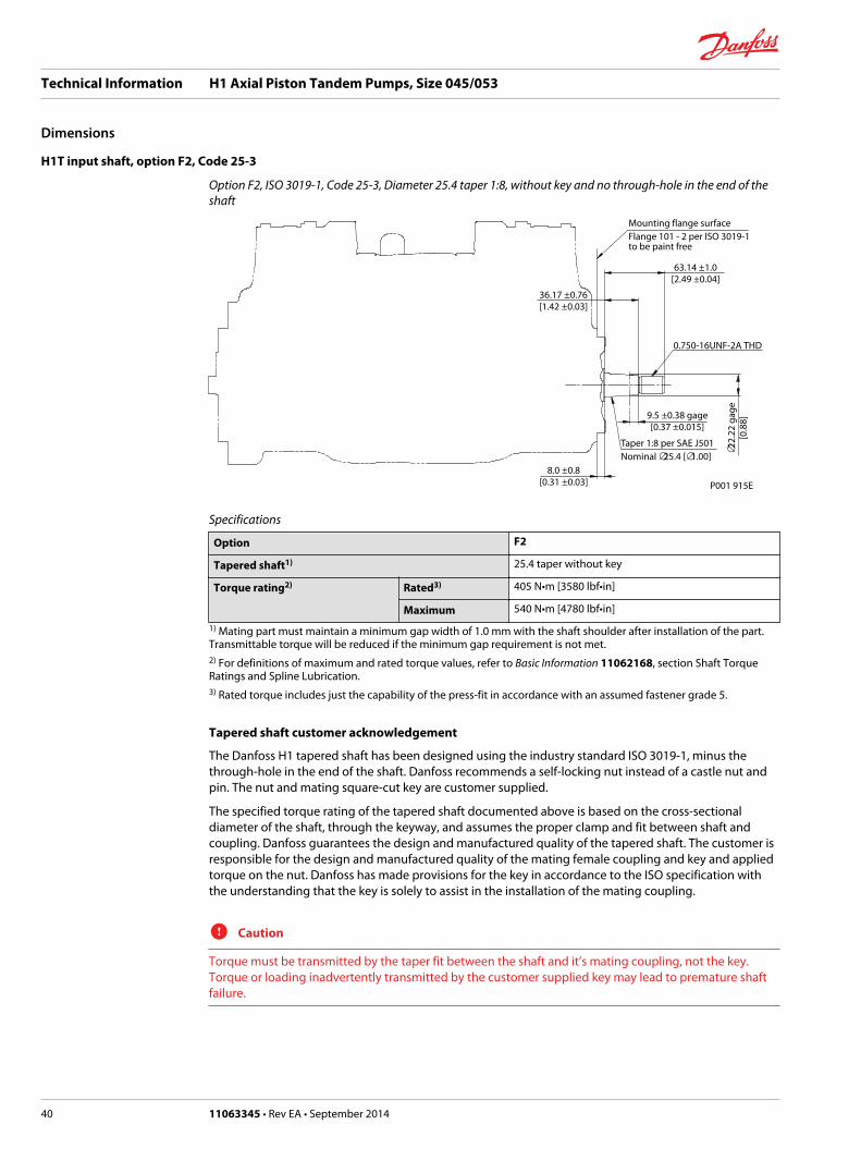
H1T input shaft, option F2, Code 25-3
Option F2, ISO 3019-1, Code 25-3, Diameter 25.4 taper 1:8, without key and no through-hole in the end of theshaft
P001 915E
8.0 ±0.8[0.31 ±0.03]
9.5 ±0.38 gage[0.37 ±0.015]
0.750-16UNF-2A THD
63.14 ±1.0[2.49 ±0.04]
36.17 ±0.76[1.42 ±0.03]
∅22.
22 g
age
[0.8
8]
Mounting flange surfaceFlange 101 - 2 per ISO 3019-1to be paint free
Taper 1:8 per SAE J501Nominal ∅25.4 [∅1.00]
Specifications
Option F2
Tapered shaft1) 25.4 taper without key
Torque rating2) Rated3) 405 N•m [3580 lbf•in]
Maximum 540 N•m [4780 lbf•in]
1) Mating part must maintain a minimum gap width of 1.0 mm with the shaft shoulder after installation of the part.Transmittable torque will be reduced if the minimum gap requirement is not met.2) For definitions of maximum and rated torque values, refer to Basic Information 11062168, section Shaft TorqueRatings and Spline Lubrication.3) Rated torque includes just the capability of the press-fit in accordance with an assumed fastener grade 5.
Tapered shaft customer acknowledgement
The Danfoss H1 tapered shaft has been designed using the industry standard ISO 3019-1, minus thethrough-hole in the end of the shaft. Danfoss recommends a self-locking nut instead of a castle nut andpin. The nut and mating square-cut key are customer supplied.
The specified torque rating of the tapered shaft documented above is based on the cross-sectionaldiameter of the shaft, through the keyway, and assumes the proper clamp and fit between shaft andcoupling. Danfoss guarantees the design and manufactured quality of the tapered shaft. The customer isresponsible for the design and manufactured quality of the mating female coupling and key and appliedtorque on the nut. Danfoss has made provisions for the key in accordance to the ISO specification withthe understanding that the key is solely to assist in the installation of the mating coupling.
C Caution
Torque must be transmitted by the taper fit between the shaft and it’s mating coupling, not the key.Torque or loading inadvertently transmitted by the customer supplied key may lead to premature shaftfailure.
Technical Information H1 Axial Piston Tandem Pumps, Size 045/053
Dimensions
40 11063345 • Rev EA • September 2014

External charge pump mounting options
P003 556E
92.0 ±0.5[3.62 ±0.02]
92.0 ±0.5[3.62 ±0.02]
91.5 ±0.5[3.60 ±0.02]
91.5 ±0.5[3.60 ±0.02]
416.
56 ±
1.0
[16.
40 ±
0.04
]
416.56 ±1.0[16.40 ±0.04]
2x 3
2.5
±0.5
[1.2
8 ±0
.02]
2x 3
2.5
±0.5
[1.2
8 ±0
.02]
Mounting flange
Mounting flange
Mounting flange
Mounting flange
Mounting flange
416.56 ±1.0[16.40 ±0.04]
419.06 ±1.0[16.50 ±0.04]
419.06 ±1.0[16.50 ±0.04]
416.
56 ±
1.0
[16.
40 ±
0.04
]
Mounting flange
Char
ge o
utle
t por
t “F”
Po
rt IS
O 1
1926
-1 -
1 1 /
16 -1
2
Char
ge o
utle
t por
t “F”
Po
rt IS
O 1
1926
-1 -
1 1 /
16 -1
2
Char
ge in
let p
ort “
S”
Port
ISO
119
26-1
- 1
5 /8 -1
2
Char
ge in
let p
ort “
S”
Port
ISO
119
26-1
- 1
5 /8 -1
2
Charge inlet port “S”
Charge inlet port “S”
Charge outlet port “F”
Charge outlet port “F”
Shaft Lc
Shaft Lc
Setting option S01
Setting option S02
A
A
B
B
A-A
B-B
Please contact Danfoss for specific installation drawings.
Technical Information H1 Axial Piston Tandem Pumps, Size 045/053
Dimensions
11063345 • Rev EA • September 2014 41

Auxiliary mounting pads without charge pump
H1T Auxiliary mounting, option H2 (SAE A, 9 teeth)
Option H2, ISO 3019-1, flange 82-2 (SAE A, 9 teeth)
P003 214E
8.1 ±0.25[0.32 ±0.01]
1.96 ±0.08[0.08 ±0.003]
2x 53.2 ±0.18[2.09 ±0.01]
2x 106.4 ±0.35[4.19 ±0.01]
R 0.8 max.[0.031]
12.7 min.[0.5]
391.5 max[15.41]
O-ring seal requiredref 82.22 [3.237] I.D. x 2.62 [0.103] cross section
4x M10 x 1.5 -6H Thd.17.0 [0.67] min. Thd. depth
Spline dataNumber of teeth : 9Pitch fraction : 16/32Pressure angle : 30°Pitch-∅ : 14.288 [0.5625]Typ of fit : Fillet root sideper : Ansi B92.1b class 7h33.6 min
[1.323]Shaft clearance
Mounting flange surfaceFlange 82 - 2 per ISO 3019-1to be paint free
∅88.
62 +0
.13
0
[
3.49
+0.0
1 ]
0
∅82.
6 +0
.08
0
[3
.25
+0.0
03]
0
Specifications
Option H2
Spline 9 teeth, 16/32 pitch
Maximum torque1) 162 N•m [1430 lbf•in]
1) For definitions of maximum and rated torque values, refer to Basic Information 11062168, section Shaft TorqueRatings and Spline Lubrication.
C Caution
Standard pad cover is installed only to retain coupling during shipping. Do not operate pump without anauxiliary pump or running cover installed.
Technical Information H1 Axial Piston Tandem Pumps, Size 045/053
Dimensions
42 11063345 • Rev EA • September 2014

H1T Auxiliary mounting, option H1 (SAE A, 11 teeth)
Option H1, ISO 3019-1, Flange 82-2 (SAE A, 11 Teeth)
P003 540E
8.1 ±0.25[0.32 ±0.01]
1.96 ±0.08[0.08 ±0.003]
2x 53.2 ±0.18[2.09 ±0.01]
2x 106.4 ±0.35[4.19 ±0.01]
R 0.8 max.[0.031]
12.7 min.[0.5]
391.5 max[15.41]
O-ring seal requiredref 82.22 [3.237] I.D. x 2.62 [0.103] cross section
4x M10 x 1.5 -6H Thd.17.0 [0.67] min. Thd. depth
Spline dataNumber of teeth : 11Pitch fraction : 16/32Pressure angle : 30°Pitch-∅ : 17.4625 [0.6875]Typ of fit : Fillet root sideper : Ansi B92.1b class 7h41.6 min
[1.638]Shaft clearance
Mounting flange surfaceFlange 82 - 2 per ISO 3019-1to be paint free
∅88.
62 +0
.13
0
[
3.49
+0.0
1 ]
0
∅82.
6 +0
.08
0
[3
.25
+0.0
03]
0
Specifications
Option H1
Spline 11 teeth, 16/32 pitch
Maximum torque1) 296 N•m [2620 lbf•in]
1) For definitions of maximum and rated torque values, refer to Basic Information 11062168, section Shaft TorqueRatings and Spline Lubrication.
C Caution
Standard pad cover is installed only to retain coupling during shipping. Do not operate pump without anauxiliary pump or running cover installed.
Technical Information H1 Axial Piston Tandem Pumps, Size 045/053
Dimensions
11063345 • Rev EA • September 2014 43

H1T Auxiliary mounting, option H3 (SAE B, 13 teeth)
Option H3, ISO 3019-1, Flange 101-2 (SAE B, 13 Teeth)
P003 307E
∅10
7.82
± 0
.12
[4.2
4 ±
0.00
5]
11.4 ± 0.25[0.45 ± 0.01]
R 0.8 max.[0.031]
12.7 max.[0.5]
391.5 max.[15.41]
Spline dataNumber of teeth : 13Pitch fraction : 16/32Pressure angle : 30°Pitch-∅ : 20.638 [0.8125]Typ of fit : Fillet root sideper : Ansi B92.1b class 7h
O-ring seal requiredRef 94.92 [3.737] I.D. x 2.62 [0.103] cross section
Mounting flange surfaceFlange 101 - 2 per ISO 3019-1to be paint free
4x M12 x 1.75 -6H Thd.18.0 [0.71] min. Thd. depth
2x 73.0 ±0.18[2.87 ±0.01]
2x 146.0 ±0.35[5.75 ±0.01]
∅10
1.65
+0.0
8
0
[4
.0 +0
.003
]
0
1.96 ±0.08[0.08 ±0.003]
42.6 min[1.677]Shaft clearance
Specifications
Option H3
Spline 13 teeth, 16/32 pitch
Maximum torque1) 395 N•m [3500 lbf•in]
1) For definitions of maximum and rated torque values, refer to Basic Information 11062168, section Shaft TorqueRatings and Spline Lubrication.
C Caution
Standard pad cover is installed only to retain coupling during shipping. Do not operate pump without anauxiliary pump or running cover installed.
Technical Information H1 Axial Piston Tandem Pumps, Size 045/053
Dimensions
44 11063345 • Rev EA • September 2014

H1T Auxiliary mounting, option H5 (SAE B-B, 15 teeth)
Option H5, ISO 3019-1, Flange 101-2 (SAE B-B, 15 Teeth)
P003 541E
∅107
.82
± 0.
12[4
.24
± 0.
005]
11.4 ± 0.25[0.45 ± 0.01]
R 0.8 max.[0.031]
12.7 max.[0.5]
391.5 max.[15.41]
Spline dataNumber of teeth : 15Pitch fraction : 16/32Pressure angle : 30°Pitch-∅ : 23.813 [0.9375]Typ of fit : Fillet root sideper : Ansi B92.1b class 7h
O-ring seal requiredRef 94.92 [3.737] I.D. x 2.62 [0.103] cross section
Mounting flange surfaceFlange 101 - 2 per ISO 3019-1to be paint free
4x M12 x 1.75 -6H Thd.18.0 [0.71] min. Thd. depth
2x 73.0 ±0.18[2.87 ±0.01]
2x 146.0 ±0.35[5.75 ±0.01]
∅101
.65
+0.0
8
0
[4
.0 +0
.003
]
0
1.96 ±0.08[0.08 ±0.003]
47.6 min[1.874]Shaft clearance
Specifications
Option H5
Spline 15 teeth, 16/32 pitch
Maximum torque1) 405 N•m [3580 lbf•in]
1) For definitions of maximum and rated torque values, refer to Basic Information 11062168, section Shaft TorqueRatings and Spline Lubrication.
C Caution
Standard pad cover is installed only to retain coupling during shipping. Do not operate pump without anauxiliary pump or running cover installed.
Technical Information H1 Axial Piston Tandem Pumps, Size 045/053
Dimensions
11063345 • Rev EA • September 2014 45

Auxiliary mounting pads with external charge pump
Option T2 (SAE A, 9 teeth)
Option T2, ISO 3019-1, flange 82-2 (SAE A, 9 teeth)
P003 553E
8.1 ±0.25[0.32 ±0.01]
1.96 ±0.08[0.08 ±0.003]
4x 5
3.2
±0.5
5[2
.09
±0.0
2]89
.5 m
ax.
[3.5
2]
520.0 max.[20.47]
482.0 max.[18.98]
19.7 min.[0.78]
R 0.8 max.[0.031]
O-ring seal requiredref 82.22 [3.237] I.D. x 2.62 [0.103] cross section
4x M10 x 1.5 -6H Thd.15.0 [0.59] min. Thd. depth
Spline dataNumber of teeth : 9Pitch fraction : 16/32Pressure angle : 30°Pitch-∅ : 14.288 [0.5625]Typ of fit : Fillet root sideper : Ansi B92.1b class 7h
33.6 min.[1.323]Shaft clearance
Mounting flange surfaceFlange 82 - 2 per ISO 3019-1to be paint free
Mounting flange
∅88.
62 +0
.13
0
[
3.49
+0.0
1 ]
0
∅82.
6 +0
.08
0
[3
.25
+0.0
03]
0
Specifications
Option T2
Spline 9 teeth, 16/32 pitch
Maximum torque1) 162 N•m [1430 lbf•in]
1) For definitions of maximum and rated torque values, refer to Basic Information 11062168, section Shaft TorqueRatings and Spline Lubrication.
C Caution
Standard pad cover is installed only to retain coupling during shipping. Do not operate pump without anauxiliary pump or running cover installed.
Technical Information H1 Axial Piston Tandem Pumps, Size 045/053
Dimensions
46 11063345 • Rev EA • September 2014

Option T1 (SAE A, 11 teeth)
Option T1, ISO 3019-1, flange 82-2 (SAE A, 11 teeth)
P003 554E
8.1 ±0.25[0.32 ±0.01]
1.96 ±0.08[0.08 ±0.003]
4x 5
3.2
±0.5
5[2
.09
±0.0
2]89
.5 m
ax.
[3.5
2]
520.0 max.[20.47]
482.0 max.[18.98]
19.7 min.[0.78]
R 0.8 max.[0.031]
O-ring seal requiredref 82.22 [3.237] I.D. x 2.62 [0.103] cross section
4x M10 x 1.5 -6H Thd.15.0 [0.59] min. Thd. depth
Spline dataNumber of teeth : 11Pitch fraction : 16/32Pressure angle : 30°Pitch-∅ : 17.4625 [0.6875]Typ of fit : Fillet root sideper : Ansi B92.1b class 7h
41.6 min.[1.638]Shaft clearance
Mounting flange surfaceFlange 82 - 2 per ISO 3019-1to be paint free
Mounting flange
∅88.
62 +0
.13
0
[
3.49
+0.0
1 ]
0
∅82.
6 +0
.08
0
[3
.25
+0.0
03]
0
Specifications
Option T1
Spline 11 teeth, 16/32 pitch
Maximum torque1) 222 N•m [1965 lbf•in]
1) For definitions of maximum and rated torque values, refer to Basic Information 11062168, section Shaft TorqueRatings and Spline Lubrication.
C Caution
Standard pad cover is installed only to retain coupling during shipping. Do not operate pump without anauxiliary pump or running cover installed.
Technical Information H1 Axial Piston Tandem Pumps, Size 045/053
Dimensions
11063345 • Rev EA • September 2014 47

Option T3 (SAE B, 13 teeth)
Option T3, ISO 3019-1, flange 101-2 (SAE B, 13 teeth)
P003 555E
11.4 ±0.25[0.45 ±0.01]
1.96 ±0.08[0.08 ±0.003]
2x 73.0 ±0.55[2.87 ±0.02]
89.5
max
.[3
.52]
520.0 max.[20.47]
482.0 max.[18.98]
19.7 min.[0.78]
R 0.8 max.[0.031]
O-ring seal requiredref 94.92 [3.737] I.D. x 2.62 [0.103] cross section
2x M12 x 1.75 -6H Thd.19.75 [0.778] min. Thd. depth Note:Excessive bolt lengthcould cause leak or damage to the unit
Spline dataNumber of teeth : 13Pitch fraction : 16/32Pressure angle : 30°Pitch-∅ : 20.638 [0.8125]Typ of fit : Fillet root sideper : Ansi B92.1b class 7h
42.6 min.[1.677]Shaft clearance
Mounting flange surfaceFlange 101 - 2 per ISO 3019-1to be paint free
Mounting flange
∅107
.82
+0.1
3
0
[
4.24
+0.0
1 ]
0
∅10
1.65
+0.0
8
0
[4
.00
+0.0
03]
0
Specifications
Option T3
Spline 13 teeth, 16/32 pitch
Maximum torque1) 222 N•m [1965 lbf•in]
1) For definitions of maximum and rated torque values, refer to Basic Information 11062168, section Shaft TorqueRatings and Spline Lubrication.
C Caution
Standard pad cover is installed only to retain coupling during shipping. Do not operate pump without anauxiliary pump or running cover installed.
Technical Information H1 Axial Piston Tandem Pumps, Size 045/053
Dimensions
48 11063345 • Rev EA • September 2014

Electric Displacement Control (EDC), option A2 (12V) / A3 (24V) H1T 045/053
Shaft Lc
Shaft Lc
Mounting flange
4x Connections :Deutsch DT04-2Pto be paint free
176.
0 m
ax[6
.93]
91.95[3.62]
P003 331E
120.05 ±1.0[4.73 ±0.04]
263.59 ±1.0[10.38 ±0.04]
147.
26 ±
1.0
[5.8
±0.
04]
209.
0 m
ax[8
.23]
2x 6
4.2
±1.0
[2.5
3 ±0
.039
]
2x 6
4.2
±1.0
[2.5
3 ±0
.039
]
58.0 ±1.0[2.28 ±0.04]
2x Case gauge port “M14” Port ISO 11926-1 – 7/16 -20∅21.0 max clearance dia for fitting
325.7 ±1.0[12.82 ±0.04]
Please contact Danfoss for specific installation drawings.
Electric Displacement Control (EDC) with MOR, option A4 (12 V) / A5 (24 V) H1T 045/053
Shaft lc
Shaft lc
Mounting flange
4x Connections :Deutsch DT04-2Pto be paint free
176.
0 m
ax[6
.93]
91.95[3.62]
P003 212E
147.
26 ±
1.0
[5.8
±0.
04]
120.05 ±1.0[4.73 ±0.04]
263.59 ±1.0[10.38 ±0.04]
209.
0 m
ax[8
.23]
2x 6
4.2
±1.0
[2.5
3 ±0
.039
]
58.0 ±1.0[2.28 ±0.04]
2x 6
4.2
±1.0
[2.5
3 ±0
.039
]
325.7 ±1.0[12.82 ±0.04]
2x Case gauge port “M14” Port ISO 11926-1 – 7/16 -20∅21.0 max clearance dia for fitting
Please contact Danfoss for specific installation drawings.
Technical Information H1 Axial Piston Tandem Pumps, Size 045/053
Dimensions
11063345 • Rev EA • September 2014 49

Manual Displacement Control (MDC), option M1, H1T 045/053
70128329-D08
Mounting flange
2x 31.5±0.8
49.3±0.8
2x 54.5±0.881.9±0.8
301.8±1.2
334.4±1.2
2x 352.2 ±1.2
2x 329.2 ±1.2
4x 2
2±0.
52x
9.6
+1
2 x
214.
7 ±2
.5
2 x
171.
8 ±1
.2
4x 2
4±0.
5
2x7.5±1°
6x11 -0.02
-0.08 8x M6x1-6H thd.
9 min. full thd. depthpaint free
Case gauge port M14ISO 11926-1 -7/16-20
Shaft
Control handle
shaft
Shaft
0
Please contact Danfoss for specific installation drawings.
Technical Information H1 Axial Piston Tandem Pumps, Size 045/053
Dimensions
50 11063345 • Rev EA • September 2014

Manual Displacement Control (MDC) with NSS, option M2, H1T 045/053
H1 Tandem 045/053 Manual Displacement Control (MDC) with NSS, option M2
70128329-D09
Mounting flange
2x 31.5±0.8
49.3±0.8
2x 54.5±0.8
81.9±0.8
301.8±1.2
334.4±1.2
2x 352.2 ±1.2
2x 329.2 ±1.2
4x 2
2±0.
52x
9.6
+1
2 x
214.
7 ±2
.5
2 x
171.
8 ±1
.2
4x 2
4±0.
5
2x7.5±1°
6x11 -0.02-0.08 8x M6x1-6H thd.
9 min. full thd. depthpaint freeCase gauge port M14ISO 11926-1 -7/16-20
Case gauge port M14ISO 11926-1 -7/16-20
Control handle shaft
Control handle shaft
2x Neutral Start Switch connectorDeutsch DT04-2Ppaint free
Shaft
0
Shaft
Neutral Start Switch connector:
Pin Assignment Pin Assignment
1 Supply OR 1 Ground
2 Ground 2 Supply
Please contact Danfoss for specific installation drawings.
Technical Information H1 Axial Piston Tandem Pumps, Size 045/053
Dimensions
11063345 • Rev EA • September 2014 51

Manual Displacement Control (MDC) with NSS, option 09, H1T 045/053
H1 Tandem 045/053 Manual Displacement Control (MDC) with NSS, option 09
70128329-D10
Mounting flange
2x 31.5±0.8
49.3±0.8
2x 54.5±0.8
81.9±0.8
301.8±1.2
334.4±1.2
2x 352.2 ±1.2
2x 329.2 ±1.24x
22±
0.5
2x 9
.6+1
2 x
214.
7 ±2
.5
2 x
171.
8 ±1
.2
4x 2
4±0.
5
2x7.5±1°
6x11 -0.02-0.08
8x M6x1-6H thd.9 min. full thd. depthpaint free
Case gauge port M14ISO 11926-1 -7/16-20
Case gauge port M14ISO 11926-1 -7/16-20
Control handle shaft
Control handle shaft
Neutral Start Switch connectorDeutsch DT04-2Ppaint free
Shaft
0
Shaft
Neutral Start Switch connector:
Pin Assignment Pin Assignment
1 Supply OR 1 Ground
2 Ground 2 Supply
Please contact Danfoss for specific installation drawings.
Technical Information H1 Axial Piston Tandem Pumps, Size 045/053
Dimensions
52 11063345 • Rev EA • September 2014

Forward-Neutral-Reverse (FNR) with MOR, option A9 (12 V) B1 (24 V), H1T 045/053
176.
0 m
ax[6
.93]
P003 211EShaft lc
147.
26 ±
1.0
[5.8
±0.
04]
4x Connections :Deutsch DT04-2Pto be paint free 120.05 ±1.0
[4.73 ±0.04]263.59 ±1.0
[10.38 ±0.04]
Mounting flange
91.95[3.62]
Shaft lc
209.
0 m
ax[8
.228
]
2x 6
4.2
±1.0
[2.5
28 ±
0.03
9]
2x 6
4.2
±1.0
[2.5
28 ±
0.03
9]
58.0 ±1.0[2.28 ±0.04]
325.7 ±1.0[12.82 ±0.04]
2x Case gauge port “M14” Port ISO 11926-1 – 7/16 -20∅21.0 max clearance dia for fitting
Please contact Danfoss for specific installation drawings.
Non Feedback Proportional Electric Control (NFPE) with MOR, option A8 (12 V) B8 (24V) H1T 045/053
2x 139.3 ± 1[5.484 ± 0.039]
64.2
± 1
[2.5
28 ±
0.0
39]
Connector: Deutsch DT04-2PTo be paint free
Connector: Deutsch DT04-2PTo be paint free
128.
4 ±
2[5
.055
± 0
.079
]
Case gauge port "M14"Port ISO 11926-1 -7/16-20∅21 max clearance dia for fitting
Plug removing can causeContamination issues
Shaft
77.2 ± 1[3.04 ± 0.039]
Mounting flange
179.
28 ±
1[7
.058
± 0
.039
]2x
152
.86
± 1
[6.0
18 ±
0.0
39]
Shaft
209
MAX
[8.2
28]
P003 363E
Please contact Danfoss for specific installation drawings.
Technical Information H1 Axial Piston Tandem Pumps, Size 045/053
Dimensions
11063345 • Rev EA • September 2014 53

Center section coupling, torque rating
Torque rating for center section coupling
P003 203E
Center coupling
Maximum torque for center coupling: 405 N•m [3580 lbf•in]
For definitions of maximum and rated torque values, refer to Basic Information 11062168, section ShaftTorque Ratings and Spline Lubrication.
Technical Information H1 Axial Piston Tandem Pumps, Size 045/053
Dimensions
54 11063345 • Rev EA • September 2014

Control Cut Off (CCO) H1T 045/053
167.2 max.[6.58]
25.3
±1.
0[1
.00
±0.0
4]
37.5
±1.
0[1
.48
±0.0
4]39
.0 ±
1.0
[1.5
4 ±0
.04]
183.32 ±1.0[7.22 ±0.04]
214.32 ±1.0[8.44 ±0.04]
216.32 ±1.0[8.52 ±0.04]
191.82 ±1.0[7.55 ±0.04]
P003 208E
Charge constr portPort ISO 11926-1 - 9/16 -18∅28.0 max. clearance dia for fitting
ConnectorDeutsch DT04-2P to be paint free
System gauge port “MB”Port ISO 11926-1 - 9/16 -18∅28.0 max. clearance dia for fitting
System gauge port “MC”Port ISO 11926-1 - 9/16 -18∅28.0 max. clearance dia for fitting
Brake gauge port “X7”Port ISO 11926-1 - 9/16 -18∅28.0 max. clearance dia for fitting
V
View V 214.32 ±1.0[8.44 ±0.04]
Please contact Danfoss for specific installation drawings.
H1T displacement limiter, 045/053 Tandem, option B
P003 209E
120.0 max.[4.72]
106.25 ±1.0[4.18 ±0.04 ]both sides277.39 ±1.0
[10.92 ±0.04 ]both sides
2x 7
4.4
±1.0
[2.9
3 ±0
.04
]bo
th s
ides
120.0 max.[4.72]
Wrench size 4(internal hex)
Wrench size 13(external hex)
Please contact Danfoss for specific installation drawings.
Technical Information H1 Axial Piston Tandem Pumps, Size 045/053
Dimensions
11063345 • Rev EA • September 2014 55

Danfoss Power Solutions is a global manufacturer and supplier of high-quality hydraulic andelectronic components. We specialize in providing state-of-the-art technology and solutionsthat excel in the harsh operating conditions of the mobile off-highway market. Building onour extensive applications expertise, we work closely with our customers to ensureexceptional performance for a broad range of off-highway vehicles.
We help OEMs around the world speed up system development, reduce costs and bringvehicles to market faster.
Danfoss – Your Strongest Partner in Mobile Hydraulics.
Go to www.powersolutions.danfoss.com for further product information.
Wherever off-highway vehicles are at work, so is Danfoss. We offer expert worldwide supportfor our customers, ensuring the best possible solutions for outstanding performance. Andwith an extensive network of Global Service Partners, we also provide comprehensive globalservice for all of our components.
Please contact the Danfoss Power Solution representative nearest you.
Local address:
Danfoss Power Solutions GmbH & Co. OHGKrokamp 35D-24539 Neumünster, GermanyPhone: +49 4321 871 0
Danfoss Power Solutions ApSNordborgvej 81DK-6430 Nordborg, DenmarkPhone: +45 7488 2222
Danfoss Power Solutions US Company2800 East 13th StreetAmes, IA 50010, USAPhone: +1 515 239 6000
Danfoss Power Solutions(Shanghai) Co., Ltd.Building #22, No. 1000 Jin Hai RdJin Qiao, Pudong New DistrictShanghai, China 201206Phone: +86 21 3418 5200
Danfoss can accept no responsibility for possible errors in catalogues, brochures and other printed material. Danfoss reserves the right to alter its products without notice. This also applies toproducts already on order provided that such alterations can be made without changes being necessary in specifications already agreed.All trademarks in this material are property of the respective companies. Danfoss and the Danfoss logotype are trademarks of Danfoss A/S. All rights reserved.
11063345 • Rev EA • September 2014 www.danfoss.com © Danfoss A/S, 2014
Products we offer:
• Bent Axis Motors
• Closed Circuit Axial PistonPumps and Motors
• Displays
• Electrohydraulic PowerSteering
• Electrohydraulics
• Hydraulic Power Steering
• Integrated Systems
• Joysticks and ControlHandles
• Microcontrollers andSoftware
• Open Circuit Axial PistonPumps
• Orbital Motors
• PLUS+1® GUIDE
• Proportional Valves
• Sensors
• Steering
• Transit Mixer Drives
Comatrolwww.comatrol.com
Schwarzmüller-Inverterwww.schwarzmueller-inverter.com
Turolla www.turollaocg.com
Valmovawww.valmova.com
Hydro-Gearwww.hydro-gear.com
Daikin-Sauer-Danfosswww.daikin-sauer-danfoss.com