H-Shaped Fractal Antennas for Dual-Band...
4
978-1-5090-6241-6/17/$31.00 ©2017 IEEE H-Shaped Fractal Antennas for Dual-Band Applications Gabriela Luciani 1 , Deisy Formiga Mamedes 2 , Alfredo Gomes Neto 2 , and Jens Bornemann 1 1 Dept. of Electrical and Computer Engineering, University of Victoria, Victoria, BC, V8W 2Y2, Canada 2 Dept. of Electrical Engineering, Federal Institute of Education, Science and Technology of Paraíba, João Pessoa, PB, Brazil Abstract—This paper presents an antenna miniaturization technique which consists in using the space-filling property offered by the fractal concept. A rectangular Koch curve is applied in a dual-band H-shaped patch radiator in order to miniaturize the antenna at each level of iteration. The approach is validated by simulated and experimental results, which demonstrate good agreement. In comparison with the conventional H-shaped antenna, the H-shaped fractal antennas of level 1 and 2 present a lower first resonant frequency. This technique achieves miniaturization of up to 30 percent of the antenna’s total size. Keywords— H-shaped antenna, Koch curve, fractal antenna. I. INTRODUCTION Due to the growth of wireless communication applications, modern telecommunication antenna systems require small dimensions, multiband characteristics, selectivity as well as low-cost profile and easy component integration capability [1, 2]. Since microstrip antennas possess some of these requirements [2], they have been widely employed. Different characteristics can be achieved when the radiating patch is designed in a different shape, such as an H-shaped antenna which is capable of a dual-band operation [3, 4]. However, such antennas still have considerable size, thus miniaturization is required. Benoit Mandelbrot first described fractal geometries in 1975. They are defined as a general description for a class where objects present an irregular shape [5, 6]. They possess self-similarity and space-filling properties in the sense that a very long line or a large surface can be built over a limited area [7, 8]. Fractal antennas have been widely studied during the past few years since fractal geometry characteristics lead to curves that are electrically long but present a compact physical space. Therefore, antenna miniaturization can be achieved [7, 9]. In this paper, the fractal concept is explored in order to evaluate its application in antenna technology. An H-shaped antenna is designed first. Then the fractal concept is applied and the behavior of the resonant frequency after antenna miniaturization iterations analyzed. The design method for a miniaturized H-shaped antenna, which is based on the space- filling property offered by the fractal concept, is discussed. II. DESIGN The initial design of the H-shaped antenna is achieved using calculations for a regular patch antenna, as described in [9], on FR-4 substrate with relative permittivity of 4.4 and thickness of 1.5 mm. Cuts on two sides of the initial patch antenna are implemented to arrive at the H-shape; dimensions are optimized in Ansoft Designer TM in order to achieve the desired resonant frequency of 2 GHz. As opposed to coaxial or aperture-coupled feeding, the proposed antenna is fed by a 50- Ω microstrip line that contributes to simple fabrication, impedance match and measurements. A quarter-wavelength impedance transformer is used to match the antenna’s input impedance to the 50-Ω line. The initial transformer section is calculated using equations provided in [10]; finally, the dimensions are optimized. A. Application of Fractal Concept In order to build a fractal geometry, two main parameters are required, the iteration factor and the number of iterations. The initial geometry of level 0 is divided by the iteration factor, and, as explained in [11], a set of geometric transformations is applied in each segment ݓቀ ௫ ௬ ቁ=ቀ ቁቀ ݔ ݕቁ+ቀ ቁ (1) where a, b, c and d control rotation and scaling transformation and e and f control linear translation. The new geometry produced by the transformation applied to level 0 can be represented by the sum of the segments as (ܣ)=⋃ ݓ (ܣ) ே ୀଵ (2) The number of iterations is the number of times it is desired to apply the set of transformations in each new geometry created previously. To maximize the miniaturization technique offered by the fractal concept, each iteration can be built using a maximum value the of iteration factor; however, due to the constraint of the H-shaped antenna’s dimensions, all edges have the same iteration factor of ¼ for L and W. Fig. 1(a), Fig. 1(b) and Fig. 1(c) show the respective H-shaped antenna (level 0), and H-shaped fractal antennas of levels 1 and 2, respectively, where the rectangular Koch curve was applied to the generator. Due to the alterations of the antenna shape, its characteristic impedance changes. In order to obtain a good return loss, some modifications in the feeding line are implemented by optimization in both levels. Simulations of the proposed antennas are carried out in Ansoft Designer TM , a software that employs the method of moments.
Transcript of H-Shaped Fractal Antennas for Dual-Band...
978-1-5090-6241-6/17/$31.00 ©2017 IEEE
H-Shaped Fractal Antennas for Dual-Band Applications
Gabriela Luciani1, Deisy Formiga Mamedes2, Alfredo Gomes Neto2, and Jens Bornemann1
1 Dept. of Electrical and Computer Engineering, University of Victoria, Victoria, BC, V8W 2Y2, Canada 2 Dept. of Electrical Engineering, Federal Institute of Education, Science and Technology of Paraíba, João Pessoa, PB, Brazil
Abstract—This paper presents an antenna miniaturization technique which consists in using the space-filling property offered by the fractal concept. A rectangular Koch curve is applied in a dual-band H-shaped patch radiator in order to miniaturize the antenna at each level of iteration. The approach is validated by simulated and experimental results, which demonstrate good agreement. In comparison with the conventional H-shaped antenna, the H-shaped fractal antennas of level 1 and 2 present a lower first resonant frequency. This technique achieves miniaturization of up to 30 percent of the antenna’s total size.
Keywords— H-shaped antenna, Koch curve, fractal antenna.
I. INTRODUCTION
Due to the growth of wireless communication applications, modern telecommunication antenna systems require small dimensions, multiband characteristics, selectivity as well as low-cost profile and easy component integration capability [1, 2]. Since microstrip antennas possess some of these requirements [2], they have been widely employed. Different characteristics can be achieved when the radiating patch is designed in a different shape, such as an H-shaped antenna which is capable of a dual-band operation [3, 4]. However, such antennas still have considerable size, thus miniaturization is required.
Benoit Mandelbrot first described fractal geometries in 1975. They are defined as a general description for a class where objects present an irregular shape [5, 6]. They possess self-similarity and space-filling properties in the sense that a very long line or a large surface can be built over a limited area [7, 8]. Fractal antennas have been widely studied during the past few years since fractal geometry characteristics lead to curves that are electrically long but present a compact physical space. Therefore, antenna miniaturization can be achieved [7, 9].
In this paper, the fractal concept is explored in order to evaluate its application in antenna technology. An H-shaped antenna is designed first. Then the fractal concept is applied and the behavior of the resonant frequency after antenna miniaturization iterations analyzed. The design method for a miniaturized H-shaped antenna, which is based on the space-filling property offered by the fractal concept, is discussed.
II. DESIGN
The initial design of the H-shaped antenna is achieved using calculations for a regular patch antenna, as described in
[9], on FR-4 substrate with relative permittivity of 4.4 and thickness of 1.5 mm. Cuts on two sides of the initial patch antenna are implemented to arrive at the H-shape; dimensions are optimized in Ansoft DesignerTM in order to achieve the desired resonant frequency of 2 GHz. As opposed to coaxial or aperture-coupled feeding, the proposed antenna is fed by a 50-Ω microstrip line that contributes to simple fabrication, impedance match and measurements. A quarter-wavelength impedance transformer is used to match the antenna’s input impedance to the 50-Ω line. The initial transformer section is calculated using equations provided in [10]; finally, the dimensions are optimized.
A. Application of Fractal Concept
In order to build a fractal geometry, two main parameters are required, the iteration factor and the number of iterations. The initial geometry of level 0 is divided by the iteration factor, and, as explained in [11], a set of geometric transformations is applied in each segment
= + (1)
where a, b, c and d control rotation and scaling transformation and e and f control linear translation. The new geometry produced by the transformation applied to level 0 can be represented by the sum of the segments as
( ) = ⋃ ( ) (2)
The number of iterations is the number of times it is desired to apply the set of transformations in each new geometry created previously. To maximize the miniaturization technique offered by the fractal concept, each iteration can be built using a maximum value the of iteration factor; however, due to the constraint of the H-shaped antenna’s dimensions, all edges have the same iteration factor of ¼ for L and W. Fig. 1(a), Fig. 1(b) and Fig. 1(c) show the respective H-shaped antenna (level 0), and H-shaped fractal antennas of levels 1 and 2, respectively, where the rectangular Koch curve was applied to the generator.
Due to the alterations of the antenna shape, its characteristic impedance changes. In order to obtain a good return loss, some modifications in the feeding line are implemented by optimization in both levels. Simulations of the proposed antennas are carried out in Ansoft DesignerTM, a software that employs the method of moments.
(a)
(b)
(c)
Fig. 1. H-shaped fractal antennas; level 0 (a), level 1 (b), level 2 (c).
III. RESULTS
This section presents simulated and measured results for the three different antennas (level 0, 1 and 2) and compares return losses, resonant frequencies and bandwidths. Moreover, the compression factor is calculated, and the effects of the fractal property on the resonant frequency in relation to the antenna dimensions are analyzed. The compression factor is the parameter that expresses the antenna miniaturization capability and compares, in percentage, how much the original antenna dimensions can be decreased during miniaturization. Also, the
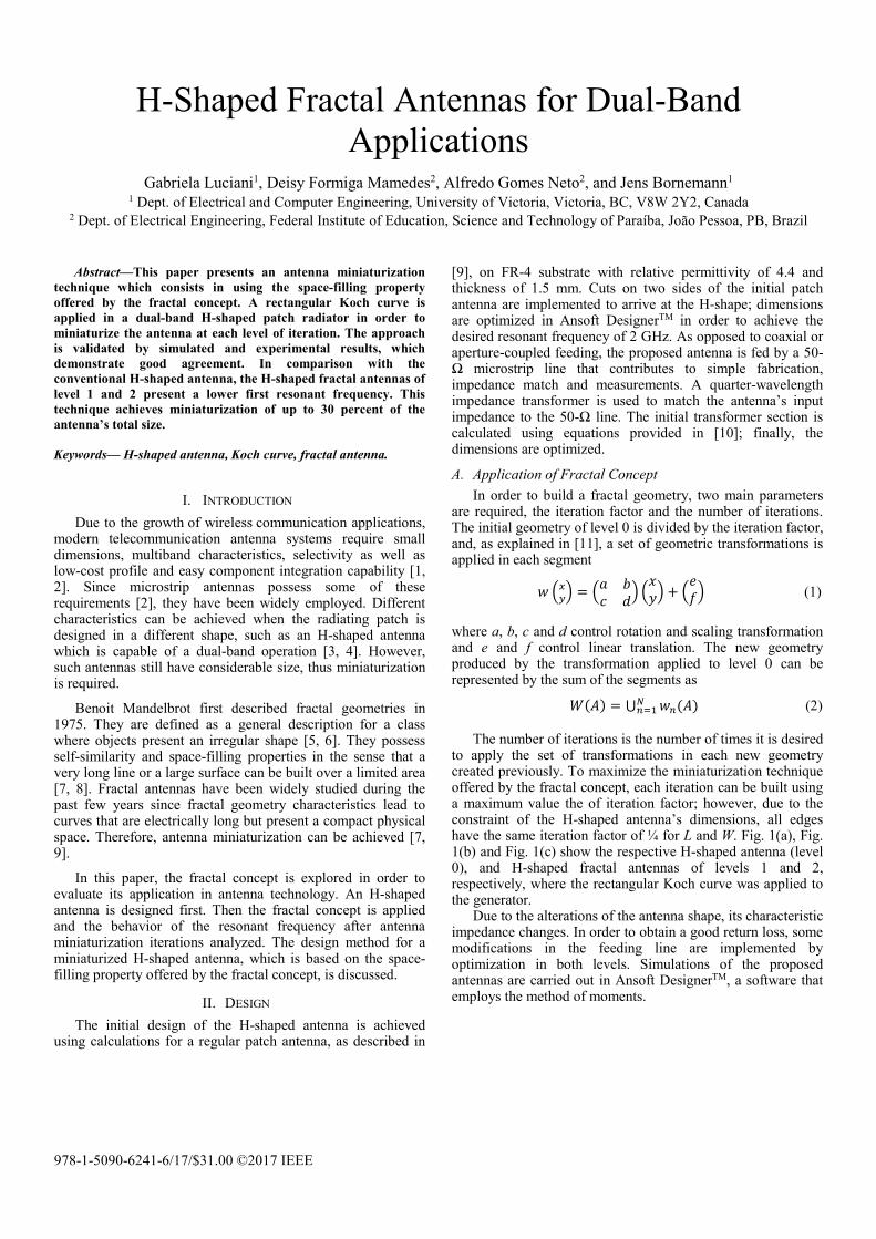
simulated radiation pattern and the current distributions are analyzed and displayed. The experimental characterization of the antennas was carried out using an Agilent N5230A vector network analyzer. Fig. 2 shows the manufactured antenna prototypes.
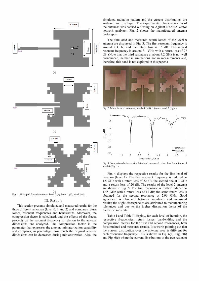
The simulated and measured return losses of the level 0 antenna are displayed in Fig. 3. The first resonant frequency is around 2 GHz, and the return loss is 15 dB. The second resonant frequency is around 3.1 GHz with a return loss of 27 dB. (Note that the third resonance at about 4.2 GHz is not well pronounced, neither in simulations nor in measurements and, therefore, this band is not explored in this paper.)
Fig. 2. Manufactured antennas, levels 0 (left), 1 (center) and 2 (right).
Fig. 3.Comparison between simulated and measured return loss for antenna of level 0 (Fig. 1).
Fig. 4 displays the respective results for the first level of iteration (level 1). The first resonant frequency is reduced to 1.5 GHz with a return loss of 22 dB, the second one at 3 GHz and a return loss of 20 dB. The results of the level 2 antenna are shown in Fig. 5. The first resonance is further reduced to 1.45 GHz with a return loss of 17 dB; the same return loss is obtained for the second resonance at 2.96 GHz. Good agreement is observed between simulated and measured results; the slight discrepancies are attributed to manufacturing tolerances and due to the higher dissipation factor of the dielectric substrate.
Table I and Table II display, for each level of iteration, the respective frequencies, return losses, bandwidths, and the compression factors for the first and second resonances, both for simulated and measured results. It is worth pointing out that the current distribution over the antenna area is different for each resonance frequency. This is shown in Fig. 6(a), Fig. 6(b) and Fig. 6(c) where the current distributions at the two resonant
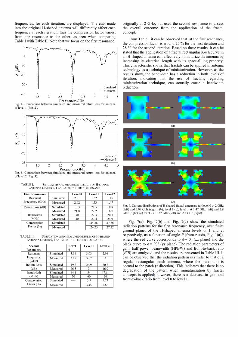
frequencies, for each iteration, are displayed. The cuts made into the original H-shaped antenna will differently affect each frequency at each iteration, thus the compression factor varies, from one resonance to the other, as seen when comparing Table I with Table II. Note that we focus on the first resonance,
Fig. 4. Comparison between simulated and measured return loss for antenna of level 1 (Fig. 2).
Fig. 5. Comparison between simulated and measured return loss for antenna of level 2 (Fig. 3).
TABLE I. SIMULATED AND MEASURED RESULTS OF H-SHAPED ANTENNA LEVELS 0, 1 AND 2 FOR THE FIRST RESONANCE
First Resonance Level 0 Level 1 Level 2 Resonant
Frequency (GHz) Simulated 2.01 1.52 1.45
Measured 2.02 1.53 1.47
Return Loss (dB) Simulated 13.3 21.5 18.8 Measured 21.8 22.2 16.7
Bandwidth (MHz)
Simulated 30 22.3 20.3 Measured 40 27.4 24.9
Compression Factor (%)
Simulated ---- 24.38 27.86
Measured 24.25 27.22
TABLE II. SIMULATION AND MEASURED RESULTS OF H-SHAPED ANTENNA LEVELS 0, 1 AND 2 FOR THE SECOND RESONATOR.
Second Resonance
Level 0
Level 1 Level 2
Resonant Frequency
(GHz)
Simulated 3.14 3.03 2.96
Measured 3.18 3.07 3
Return Loss (dB)
Simulated 19.2 24.9 20.7 Measured 26.5 19.1 16.9
Bandwidth (MHz)
Simulated 64.1 54 47.61 Measured 70 60 50
Compression Factor (%)
Simulated ---- 3.5 5.73
Measured 3.45 5.66
originally at 2 GHz, but used the second resonance to assess the overall outcome from the application of the fractal concept.
From Table I it can be observed that, at the first resonance, the compression factor is around 25 % for the first iteration and 28 % for the second iteration. Based on these results, it can be stated that the application of a fractal rectangular Koch curve in an H-shaped antenna can effectively miniaturize the antenna by increasing its electrical length with its space-filling property. This characteristic shows that fractals can be applied in antenna technology as a technique of miniaturization. However, as the results show, the bandwidth has a reduction in both levels of iteration, indicating that the use of fractals, regarding miniaturization technique, can actually cause a bandwidth reduction.
(a)
(b)
(c)
Fig. 6. Current distributions of H-shaped fractal antennas; (a) level 0 at 2 GHz (left) and 3.07 GHz (right), (b), level 1 (b), level 1 at 1.47 GHz (left) and 2.9 GHz (right), (c) level 2 at 1.37 GHz (left) and 2.8 GHz (right).
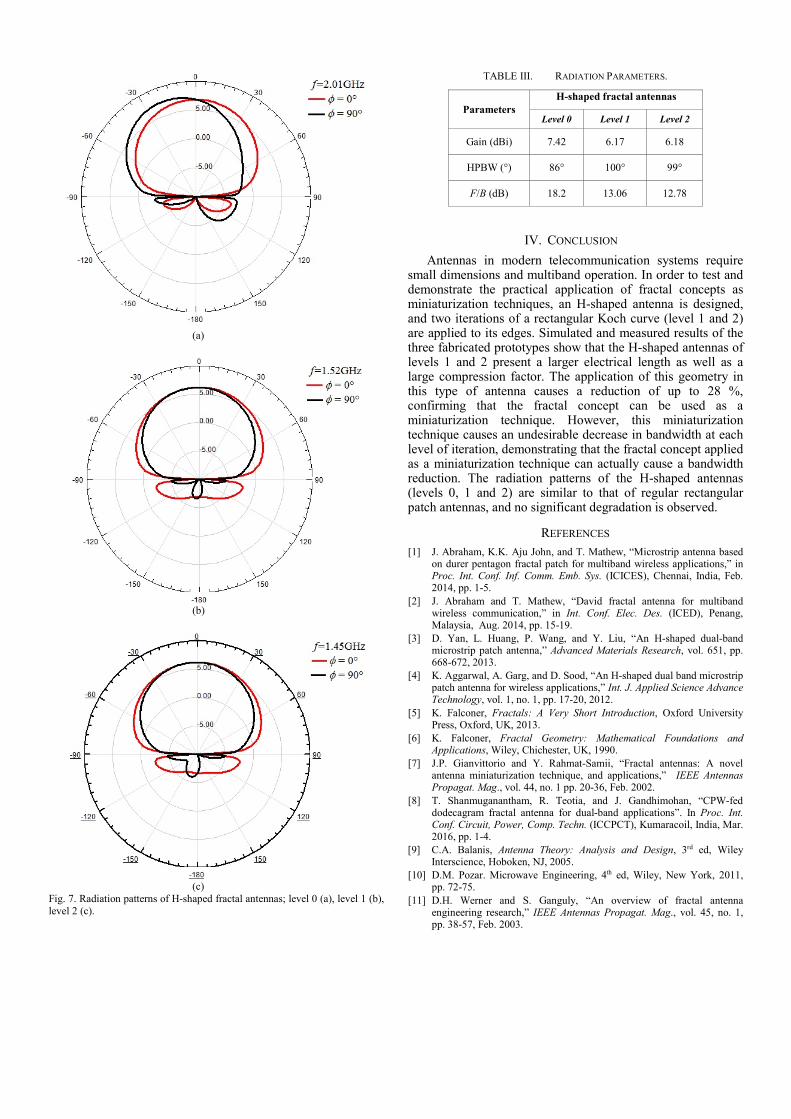
Fig. 7(a), Fig. 7(b) and Fig. 7(c) show the simulated radiation patterns for the first resonance frequency, over finite ground plane, of the H-shaped antenna levels 0, 1 and 2, respectively, as a function of angle θ (from z axis, Fig. 1(a)), where the red curve corresponds to φ = 0° (xz plane) and the black curve to φ = 90° (yz plane). The radiation parameters of gain, half power beamwidth (HPBW) and front-to-back ratio (F/B) are analyzed, and the results are presented in Table III. It can be observed that the radiation pattern is similar to that of a regular rectangular patch antenna, where the maximum is normal to the patch (z direction). This indicates that there is no degradation of the pattern when miniaturization by fractal concepts is applied; however, there is a decrease in gain and front-to-back ratio from level 0 to level 1.
(a)
(b)
(c)
Fig. 7. Radiation patterns of H-shaped fractal antennas; level 0 (a), level 1 (b), level 2 (c).
TABLE III. RADIATION PARAMETERS.
Parameters H-shaped fractal antennas
Level 0 Level 1 Level 2
Gain (dBi) 7.42 6.17 6.18
HPBW (°) 86° 100° 99°
F/B (dB) 18.2 13.06 12.78
IV. CONCLUSION
Antennas in modern telecommunication systems require small dimensions and multiband operation. In order to test and demonstrate the practical application of fractal concepts as miniaturization techniques, an H-shaped antenna is designed, and two iterations of a rectangular Koch curve (level 1 and 2) are applied to its edges. Simulated and measured results of the three fabricated prototypes show that the H-shaped antennas of levels 1 and 2 present a larger electrical length as well as a large compression factor. The application of this geometry in this type of antenna causes a reduction of up to 28 %, confirming that the fractal concept can be used as a miniaturization technique. However, this miniaturization technique causes an undesirable decrease in bandwidth at each level of iteration, demonstrating that the fractal concept applied as a miniaturization technique can actually cause a bandwidth reduction. The radiation patterns of the H-shaped antennas (levels 0, 1 and 2) are similar to that of regular rectangular patch antennas, and no significant degradation is observed.
REFERENCES [1] J. Abraham, K.K. Aju John, and T. Mathew, “Microstrip antenna based
on durer pentagon fractal patch for multiband wireless applications,” in Proc. Int. Conf. Inf. Comm. Emb. Sys. (ICICES), Chennai, India, Feb. 2014, pp. 1-5.
[2] J. Abraham and T. Mathew, “David fractal antenna for multiband wireless communication,” in Int. Conf. Elec. Des. (ICED), Penang, Malaysia, Aug. 2014, pp. 15-19.
[3] D. Yan, L. Huang, P. Wang, and Y. Liu, “An H-shaped dual-band microstrip patch antenna,” Advanced Materials Research, vol. 651, pp. 668-672, 2013.
[4] K. Aggarwal, A. Garg, and D. Sood, “An H-shaped dual band microstrip patch antenna for wireless applications,” Int. J. Applied Science Advance Technology, vol. 1, no. 1, pp. 17-20, 2012.
[5] K. Falconer, Fractals: A Very Short Introduction, Oxford University Press, Oxford, UK, 2013.
[6] K. Falconer, Fractal Geometry: Mathematical Foundations and Applications, Wiley, Chichester, UK, 1990.
[7] J.P. Gianvittorio and Y. Rahmat-Samii, “Fractal antennas: A novel antenna miniaturization technique, and applications,” IEEE Antennas Propagat. Mag., vol. 44, no. 1 pp. 20-36, Feb. 2002.
[8] T. Shanmuganantham, R. Teotia, and J. Gandhimohan, “CPW-fed dodecagram fractal antenna for dual-band applications”. In Proc. Int. Conf. Circuit, Power, Comp. Techn. (ICCPCT), Kumaracoil, India, Mar. 2016, pp. 1-4.
[9] C.A. Balanis, Antenna Theory: Analysis and Design, 3rd ed, Wiley Interscience, Hoboken, NJ, 2005.
[10] D.M. Pozar. Microwave Engineering, 4th ed, Wiley, New York, 2011, pp. 72-75.
[11] D.H. Werner and S. Ganguly, “An overview of fractal antenna engineering research,” IEEE Antennas Propagat. Mag., vol. 45, no. 1, pp. 38-57, Feb. 2003.