,H Infrared ..I - NASA · infrared sensor program, not in terms of the best way to implement an...
108
*'. . ' , ; q'- -- ,.7 (NASA-CR-16 175) MATERIALS PEOCESSIbG N81-23100 .. . j , THRZSdOLD REPORT. 1 : S EHICOUDUCTOB C bRYbTALS FOR INFRARED DETECTORS Final i Unclas Reporr (System Plr ~ning Corp., Arlingtou, ... a ) 108 p KC AOb/fiP AS.? CSCL LZA G3/12 42253 + . S : - I i: * 1. ~~mi~~nductor ciysral:; ' B i a : <+ , H P I Y for Infrared i.$etec%or< . 11 c <' .- t .. ' a . I . - , A FINAL BEPORT -f . - ..I * ( C SPC 564 https://ntrs.nasa.gov/search.jsp?R=19810014567 2019-06-02T13:03:22+00:00Z
Transcript of ,H Infrared ..I - NASA · infrared sensor program, not in terms of the best way to implement an...
*'. . ' , ; q'- -- ,.7 (NASA-CR-16 1 7 5 ) MATERIALS PEOCESSIbG N81-23100 .. . j
, T H R Z S d O L D REPORT. 1 : S EHICOUDUCTOB C
b R Y b T A L S FOR INFRARED DETECTORS Final i
Unclas Reporr ( S y s t e m P l r ~ n i n g C o r p . , A r l i n g t o u , ... a ) 1 0 8 p K C AOb/fiP A S . ? CSCL L Z A G3/12 42253 + . S :
- I i : * 1 . ~ ~ m i ~ ~ n d u c t o r ciysral:; ' B i a :<+ ,H PIY for Infrared i.$etec%or< .
11 c < ' .- t .. 'a . I . - , A FINAL BEPORT -f
. - ..I * ( C
SPC 564
https://ntrs.nasa.gov/search.jsp?R=19810014567 2019-06-02T13:03:22+00:00Z
SYSTEM PLANNING CORPORATION - '-- 1500 Wilson Boulevard Suite 1500 Arlin~ton, Virginia 22209 llO3l 841.2800
Systems Research & Engineering Division
SPC Log NO. 80-2022
COPY
MATERIALS PROCESSING THRESHOLD REPORT., I. Semiconductor Crystals for Infrared Detectors
FINAL REPORT SPC 564
February 1980
Earl V. Sager Terence R. Thompson Robert G. Nagler
Prep3red under
Contract NAS8-33554
Sponsored by
National Aeronautics and Space Administration George C. Marshall Space Flight Center
Marshall Space Flight Center Alabama 3581 2
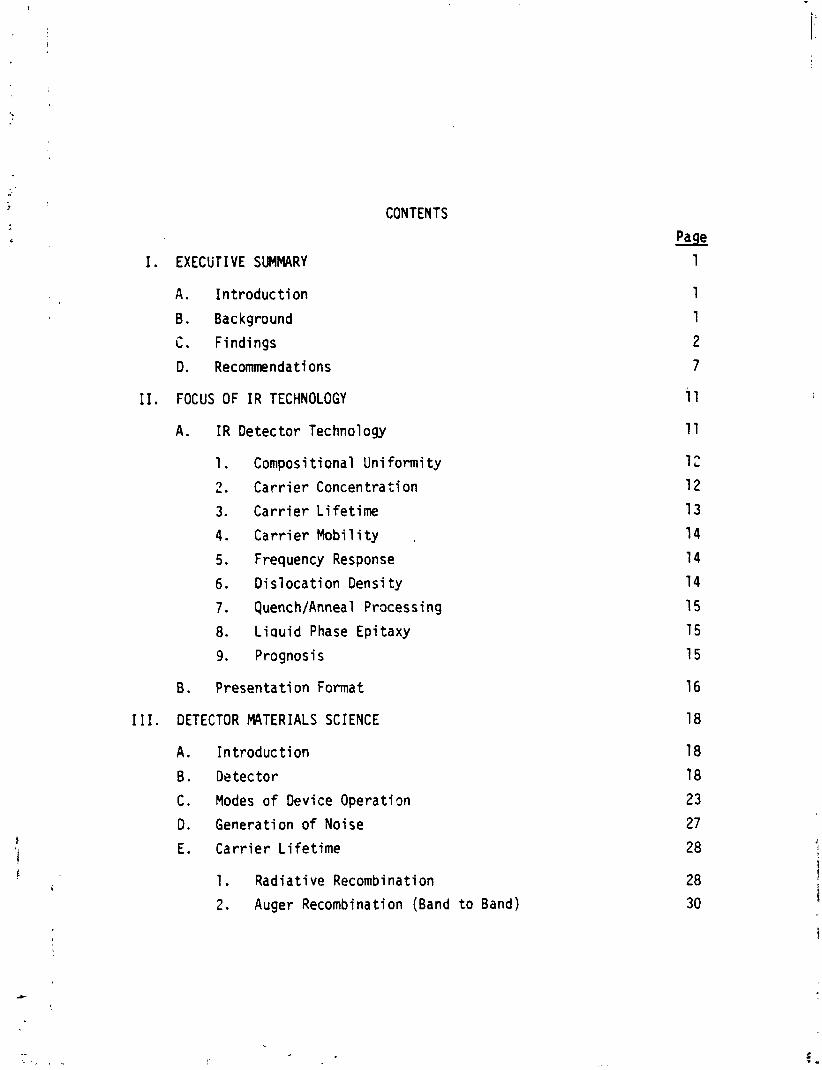
CONTENTS
I. EXECUTIVE SUMMARY
A . I n t roduc t i on
B . Background
i. Findings
D. Recommendations
I I. FOCUS OF I R TECHNOLOGY
A. I R Detector Technology
Compositional Uni formi ty
C a r r i e r Concentration
C a r r i e r L i fe t ime
C a r r i e r Mobi 1 i t y .
Frequency Response
D is loca t ion Density
Quench/Anneal Processing
L i a u i d Phase Epi taxy
Prognosi s
B . Presentat i on Format
I I I. DETECTOR MATERIALS SCIENCE
A. I n t roduc t i on
B. Detector
C. Modes o f Device Operation
D. Generation of Noise
E. Car r i e r L i f e t i m e
1. Radiat ive Recombination
2. Auger Recombination (Band t o Band)
Page
1
3. Shockley-Read Combination
Page 3 1
F. Optimal Performance o f In f ra red Detectors
1. I n t r i n r i c Photoconductive Detectors
2. E x t r i n s i c Photoconductive Detectors
3. Photovol t a i c Detectors
G. Dependence o f Bac kground-Limi ted Spectral Detect i v i t y
H. Simple S e n s i t i v i t y Analysis o f Spectra7 De tec t i v i t y
I. Device Performance
3. Mater ia l S t ruc ture and Devi ce Performance
K. Current D r i v i n g Forces i n Detector Design
I V . METHODS AND PROBLEMS OF CRYSTAL GROWTH
A. Crys ta l Growth
B. Crys ta l Defc,ts
C. The Crys ta l Growth Inter face
1. Component Vo la t i 1 i t y
2. Component Segrega ti on
D. I n s t a b i l i t y Mechanisms
1. Grav i ty Driven Convection
2. Maragoni Convecti on
3. Double D i f f u s i v e Convection
4 . Addi t iona l Flow I n s t a b i l i t i e s
E. Growth Techniques
1. Czochral s k i Growth
2. Boat o r Capsule Growth
3. Growth From So lu t i on
4. Growth From a Vapor
V. POTENTIAL PROGRAM DIRECTIONS AND THRUSTS
A. Se lec t ing Mater ia l Combinations
1 . Elemental, B inary , and Ternary Compounds
2. Impu r i t i es , Contaminants, Compensators, and Dopants
B. Measuring Fundamental Mate r i a1 P rope r t i es
C . Eva1 u a t i n g C rys ta l Growth Mecbanizations
1. P u l l From a C ruc ib l e (e.g., Czochra lsk i )
2. F l o a t i n g Me1 t Zone
3. Contained Me1 t s (e.g. , Bridgeman)
4. Rheocasting
5. L i q u i d Phase Ep i taxy
i. Vapor Phase Epi taxy
7. Molecular Beam Ep i taxy and Diode Spu t t e r i ng
D. Assessing Mater i a1 Performance f o r De tec t ion App l i ca t i ons
E. Eva lua t i ng Time Decay i n Performance
F. Producing Real Devices
REFERENCES
PERTINENT PUBLICATIONS
Page
7 9
I. EXECUTIVE SUMMARY
A. INTRODUCTION
1 i n 1978, System Planning Corporat ion (SPC) conducted a survey f o r
NASA of defense-related mater ia ls research a c t i v i t i e s ongoing w i t h f n the
Department o f Defense and p r i v a t e industry . The purpose was t o determine
the prime areas o f mater ia ls research and t o f i n d out i f researchers had
given thought t o mater ia ls processing i n space. The outcome o f t he survey
was t o i s o l a t e s p e c i f i c areas i n which u l t i m a t e ma te r ia l s performance was
not c u r r e n t l y achievable and which might be improved by processing i n the
zero g r a v i t y environment o f space. Based on t h a t survey, NASA selected
SPC t o study i n depth one o r more o f the promising areas o f ma te r i a l s
research. The purpose o f the study was t o look f u r t h e r i n t o the poss ib le
benef i ts o f mater ia ls precessing i n space and t o devise a presentat ion by
which NASA could generate i n t e r e s t on the p a r t o f DOD agencies i n conducting
mater ia l s processing experiments on f u t u r e Space Shu t t l e s c i e n t i f i c missions.
The r e s u l t s of the study are documented i n t h i s repor t .
B. BACKGROUND
The s h o r t - t e n prospects f o r materials processing i n space inc lude i t s
use as a research t o o l and i n some r a r e instances i t s c a p a b i l i t y t o prov ide
s u f f i c i e n t mater ia l f o r p r a c t i c a l uses. It was f e l t t h a t i n i t i a l l y , a t
leas t , t h i s e f f o r t would be most p r o f i t a b l y d i rec ted towards a mater ia l f o r
which both poss ib i lS t i es ex is t . For t h i s reason, semiconductor i n f r a r e d .
'J. W. Whybrew, e t a]., Analysis o f Mater ia ls Processinq i n Space, SPC 390, November 1978.
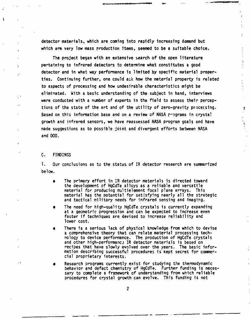
detector materials, which are coming i n t o r ap id l y increasing demand but
which are very law mass production items, seemed t o be a su i tab le choice,
The pro jec t began w i th an extensive search of the open l i t e r a t u r e
perta in ing t o in f ra red detectors t o determine what const i tutes a good
detector and i n what way performance i s l i m i t e d by speci f ic material proper-
t ies . Continuing further, one could ask how the mater ia l property i s re la ted
t o aspects of processing and how undesirable character is t ics might be
e l iminated. With a basic understanding o f the subject i n hand, interviews
were conducted w i th a number of experts i n the f i e l d t o assess t h e i r percep-
t ions of the s ta te of the a r t and of the u t i l i t y of zero-gravity pracersing.
Based on t h i s information base and on a review of NASA pvagrams i n c rys ta l
growth and infrared sensors, we have reassessed NASA program goals and have
made suggestions as t o possible j o i n t and divergent ef for ts between NASA
and DOD,
C. FINDINGS
1. Our conclusions as t o the s ta tus o f I R detector research are sumnari zed
be1 ow.
The primary e f f o r t i n I R detector mater ia ls i s d i rected toward the development o f HgCdTe a l loys as a r e l i ab le and ve rsa t i l e mater ia l f o r producing mu1 t ielement foca l plane arrays. This mater ia l has the potent ia l f o r satJsfy ing near ly a1 1 the s t ra teg ic and t a c t i c a l m i l i t a r y needs f o r in f ra red sensing and imaging.
e The need f o r high-quali t y HgCdTe c rys ta ls i s cur rent ly expanding a t a geometric progression and can be expected t o increase even fas te r i f techniques are devised t o increase r e l i a b i l i t y and 1 ower css t . There i s a serious lack o f physical knowledge from which t o devise a comprehensive theory tha t can r e l a t e material processing tech- nology t o device performance. The production o f HgCdTe c rys ta ls and other h igh-per fomnc? I R detector mater ia ls i s based on recipes tha t have slowly evolved over the years. The basic i n f o r - mation describing successful procedures i s kept secret for comner- cia1 propr ietary interests.
Research programs cur rent ly ex i s t f o r studying the thermodynamic behavior and defect chemistry o f HgCdTe. Further funding i s neces- sary t o complete a framework of understanding from which re1 Sable procedures f o r c rys ta l growth can evolve. This funding i s not
l i k e l y t o or ig inate w i th the comnercial suppliers o f I R c rys ta ls and devices.
A r o l e f o r space processing o f I R c rys ta ls cannot now be proper ly determined because of the inconsistencies i n the resu l t s o f ground- based research. Fundamental research on ground-based c rys ta l growth f a c i l i t i e s i s needed i n order t o quantify the contr ibut ions o f other processing variables r e l a t i v e t o the potent ia ls i n contra11 ing convection and segregation by reducing gravi ty. Given a1 ternat ives and a 1 i m i ted budget, any research i s most 1 i kely t o choose the less exot ic ground-based research program.
2. Some s i gn i f i can t numbers characterizing the capabi 1 i t y of present
HgCdTe production techniques are given be1 ow.
0 Compositional uniformity, which determines the long wavelength cutoff, i s claimed t o be w i t h i n 1 t o 5 percent across a l-cm wafer. (Device performance, characterized by Or may vary by about 50 percent.
0 Excess ca r r i e r concentration a t 7 7 O K i s w i th in a compensated range o f 1 t o 2 x 1014 cm-3. This ex t r i ns i c value may be due t o defects o r impur i t ies.
0 Carr ier l i f e t imes are l i m i t e d by ex t r i ns i c propert ies t o about 1 usec.
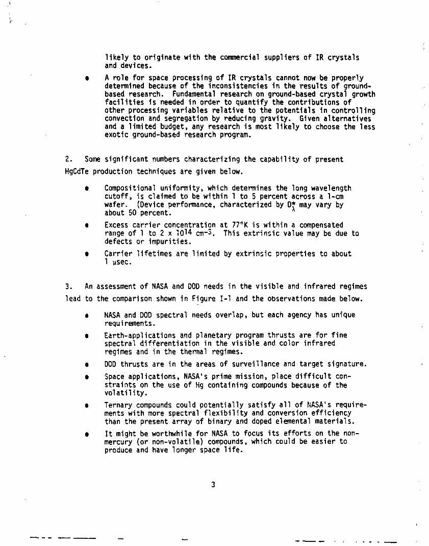
3. An assessment o f NASA and DO0 needs i n the v i s i b l e and in f ra red regimes
lead t o the comparison shown i n Figure 1-1 and the observations made below.
0 NASA and DOD spectral needs overlap, but each agency has unique requirements. Earth-appl ica t ions and planetary program thrusts are for f i n e spectral d i f f e ren t i a t i on i n the v i s i b l e and color in f ra red regimes and i n the thermal regimes.
0 DO0 thrusts are i n the areas of survei l lance and target signature.
Spaceapplications, NASA'sprimemission, p l a c e d i f f i c u l t ccn- s t r a i n t s on the use of Hg containing compounds because of the v o l a t i l i t y .
0 Ternary compounds could po ten t i a l l y sa t i s f y a1 1 o f NASA's require- ments w i th more spectral f l e x i b i l i t y and conversion e f f ic iency than the present array o f binary and doped elemental materials.
0 It might be worthwhile f o r NASA t o focus i t s ef for ts on the non- mercury (o r non-volat i le) compounds, which could be easier t o produce and have longer space l i f e .
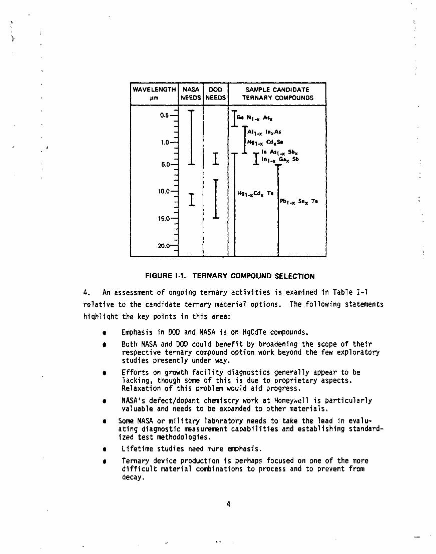
FIGURE 1-1. TERNARY COMPOUND SELECT ION
WAVELENGTH ~m
1 .o
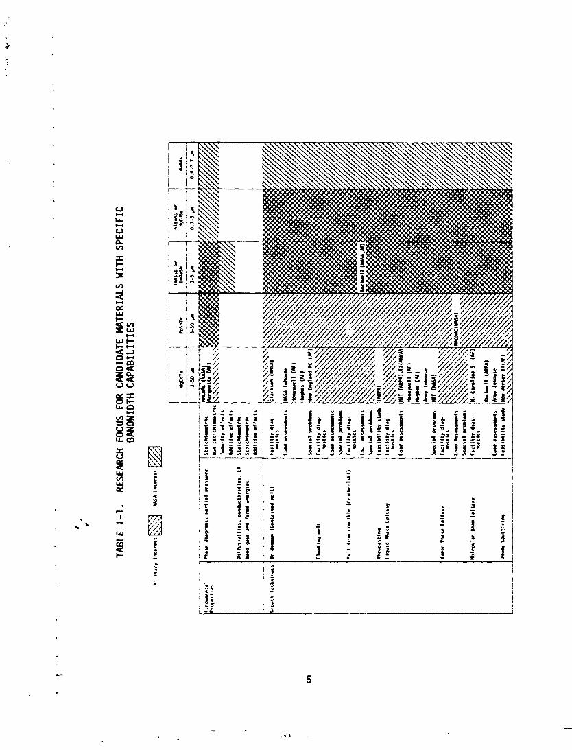
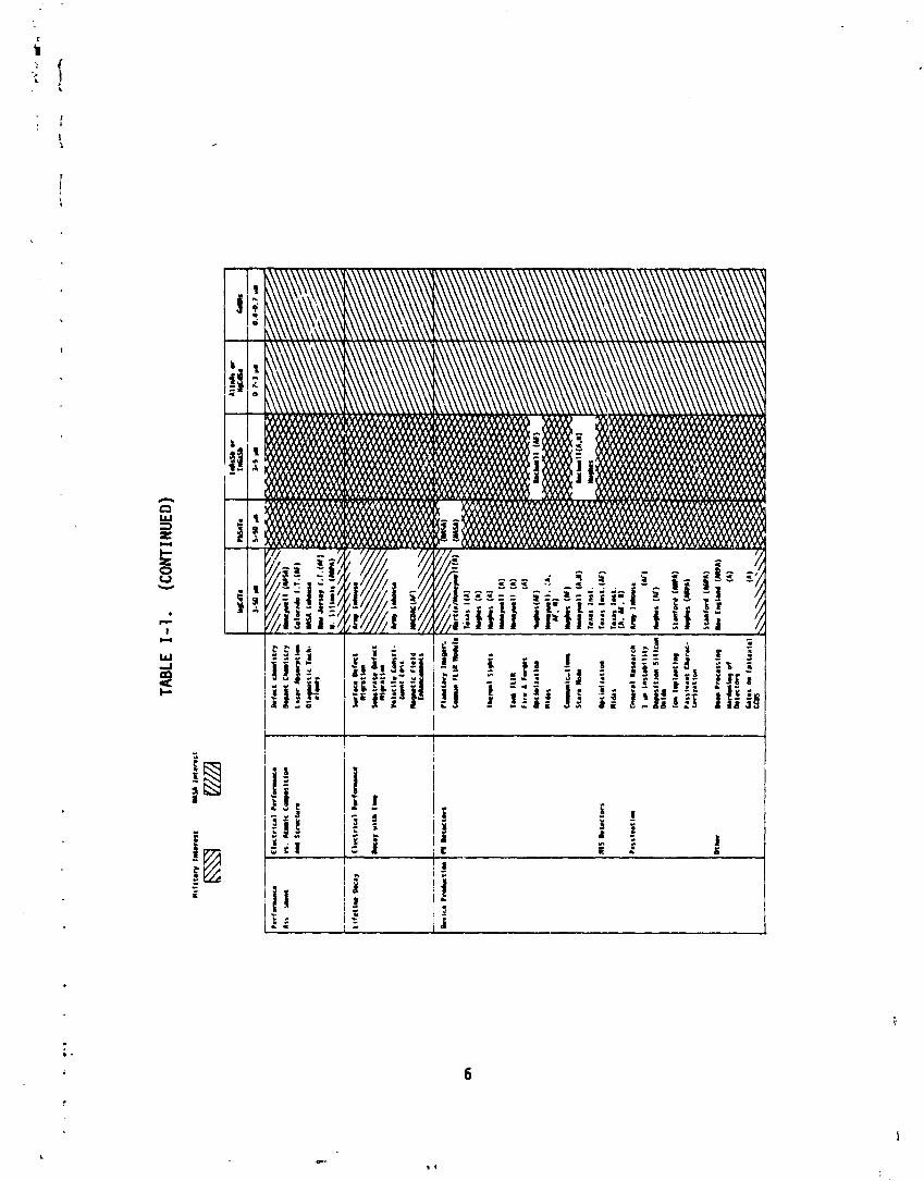
4. An assessment o f ongoing te rnary a c t i v i t i e s i s examined i n Table 1-1
r e l a t i v e t o the candidate te rnary mater ia l options. The fo l l ow ing statements
h i q h l i q h t the key po in ts i n t h i s area:
0 Emphasis i n DOD and NASA i s on HgCdTe compounds.
a Both NASA and DOD could b e n e f i t by broadening the scope of t h e i r respect ive te rnary compound op t ion work beyond t h e few exploratory studies present ly under way.
I
SAMPLE CANDIDATE TERNARY COMPOUNDS -
GI Nl-x A+ I NASA
NEEDS
0 E f f o r t s on growth f a c i l i t y diagnost ics general ly appear t o be 1 acking, though some of t h i s i s due t o p rop r ie ta ry aspects. Relaxat ion o f t h i s problem would a i d progress,
DOD NEEDS
I 5.0 lo,ojl 15.0
- 20.0
e NASA's defect/dopant chemistry work a t Honepel 1 i s p a r t i c u l a r l y valuable and needs t o be expanded t o other mater ia ls .
I
I -
0 Some NASA o r m i l i t a r y labora tory needs t o take the lead i n evalu- a t i n g diagnost ic measurement c a p a b i l i t i e s and es tab l ish ing standard- i zed t e s t methodologies.
HOI-~C~, fe
0 L i fe t ime studies need mdre emphasis.
mt,x Sn, To
a Ternary device product ion i s perhaps focused on one o f the more d i f f i cul t mater ia l combinations t o process and t o prevent from decay.
TABLE
1-1.
RESEARCH FOCUS F
OR CANDIDATE MATERIALS WITH SPECIFIC
BANW
IDTH
CAPABILITIES
Pu
ll IN
cry
ible
[C
ZO
C)I
~
Load
.S
Xs
Mt
%
Sp
cc
al H
la
Fu
lllt
y 4
1- ID
Itlc
s
la
. r
rx
sv
rt
s
I Lo
r .
Is
e%
~l
S
Fo
ss
ibtl
lly
std
y
TA6L
E 1-
1.
(CO
NTIN
UED)
The fo l lowing courses of ac t ion are reconmended for consideration by
the Materials Processing i n Space Program. I n i t i a l l y we are suggesting
some workshop-li ke meetings, f i r s t t o review needs and assess di rect ions,
and then t o del ineate speci f ic s c i e n t i f i c focuses and the possibi 1 i t i e s
for ' j o i n t o r i n te r re la ted ef for ts between NASA and DOD.
1. An in terna l reevaluation needs t o be made of the NASA v i s i b l e and
in f ra red sensor program, not i n terms of the best way t o implement an array
sensor w i t h maximum DOD inheritance, but ra ther I n tenns o f the spec i f i c
NASA detector needs and the spec i f i c matches w i t h the spectral capabi! i t y
potent ia ls of the f u l l array of feasible ternary (and possibly quaternary)
compounds. This would entai 1 :
0 Gathering appropriate representatives from the Headquarters Program Offices for Mater ia ls Processin (EM), Resource Appl ica- t i ons (ER), Environmental Appl icat ions 9 EM), Planetary (SL), Astronomy (SA), and Sensor Research (RE) and From t h e i r mission and technology counterparts a t MSFC, GSFC, LaRC, JPL, JSC, and NSTL/ERL.
0 Exploring program needs f o r spectral range and ~arrowness o f ind iv idua l bandwidths, constra ints i n opt ics and detector-array packaging due t o space imp1 ementation, and the material options for sa t i s fy ing these needs.
2. An internal /external evaluation needs t o bemade of the p r i o r i t y
d i rec t ions for focus i n v i s i b l e and infrared detector research--from funda-
mental propert ies, t o c rys ta l growth dynamics , t o the understanding o f
defect and addi t ive chemistry, and t o the in te rp lay w i t h other phases o f the
data processing chain through improved understanding of layer ing or o t h e ~
forms of attachment junctions. Three types of meetings, conducted i n series, are recommended:
The subset of NASA personnel involved spec i f i ca l l y w i t h the c rys ta l growing and device junct ion problem i n detector produc- t i o n needs t o meet w i t h selected un ive rs i t y personnel (MIT, Marquette, Stanford, etc. ) t o evaluate biases and constraints i n NASA in te res ts and capabi l i t ies . F m t h i s background, they can then establ ish and iden t i f y speci f ic research needs, establ ish s c i e n t i f f c a l l y defendable j u s t i f i c a t i o n f o r program a c t i v i t y , and establ ish basic p r i o r i t i e s f o r the app l ica t ion o f fur.ds.
a The second meetfng i n t h i s external interface ser ies would involve a subset o f the NASA and un ive rs i t y personbe1 (cannot be la rger than the number o f new par t ic ipants) and a representat ive set o f industry personnel from the seven o r more i n r s t r y organizations carry ing out the major a c t i v i t y i n detector science and comaercial c rys ta l growth. This would include two Honeywell organizations, two Hugh s organi zations , Texas Instruments, Rockwel 1 , and McDonnel 1 Douglas.7 The purpose of t h i s meeting i s t o establ ish, a t l eas t qua l i ta t i ve ly , what has been done i n e ~ c h area, whet f e a s i b i l i t y questions have already been established but not reported, and where the greatest i n t e res t and capab i l i t y ex is ts f o r each task area. A p r i o r i t y adjustment i s expef ed t o take place a f ter t h i s meeting.
r The t h i r d meeting i n t h i s external i n te r face series would involve the same subset of NASA and un ive rs i t y people plus representatives from each of the major m i l i t a r y visible-and-infrared sensor programs and device technology programs. I n t h i s meeting, the resu l t s o f previous meetings would be presented, the opportunit ies f o r cooperative ventures discussed, and arrangements would be made f o r fu r the r meetings a t ind iv idua l locat ions t o expose the ideas t o a wider audience, t o explore i n more de ta i l these o r other j o i n t opportunit ies, and t o estab l ish an i n i t i a l basis for cooper- a t i ve e f for t . Again we expect another a d f ~ s h e n t i n p r i o r i t i e s from t h i s t h i r d meeting and the add i t iona l meetings i t generates.
3. There are a number o f areas which we recornend f o r pa r t i cu l a r consider- at ion. These are s u m r i z e d below and dfscussed fur ther i n Section V.
r A l l of the possible ternary (and SGW o f the quaternary) optiocs need t o be systematical ly assessed as t o t h e i r potent ia l for continuous control (through composition var ia t ion) o f the effec- t i v e cutoff wavelength. Pa r t i cu l s r a t ten t ion should be given t o v o l a t i l i t y of consti tuents i n the space environment and any pecu l i a r i t i e s o f chemistry tha t might portend decay i n a i r c r a f t o r other earth environments.
e Phase diagrams should be generated f o r a l l of the material combinations t ha t appear promising f r o m e i t he r a performance o r l i f e t ime po in t o f view.
(I Diagnosis o f the actual thermal g e m t r i e s of each o f the major c rys ta l growing configurations i s a basic datum tha t needs t o be established before much sense can be made out of var ia t ions i n the material input load:: i n terms of stoichiometry, graded com- i jos i t ions i n s t a r t i ng volumes, impur i ty and addi t ive var iat ions, e t ~ . These diaqnostic data are generally not avai lable, e i t he r through
- - - - -
l ~ h e a c t i v i t y represented by Reference 5 involves these people, but addresses the wrqng issues.
neglect o r lack of report ing. Although i t needs t o be assessed i n more de ta i l , our assessment implies t ha t NASA should take the lead i n the bulk techniques and i n vapor phase epitaxy. The m i l i t a r y might take the lead i n l i q u i d phase epitaxy and mole- cu lar beam epitaxy. 80th should look a t remelt techniques w i th high-intensi t y loca l heating.
0 Defect and dopant chemistry ef for ts need t o be expanded t o a wider va r ie ty o f ternary materials bcsed on the more general material assessment and phase didgram resul ts. S t o i c h i m e t r i c and nonstoichiometric mixtures, var ia t ions ? n impur i t ies and contaminant 1 evel s, var ia t ions i n dopant and compensator 1 evel s , growth technique contr ibutions, and anneal i ng effects a1 1 need close study. M i l i t a r y emphasis should be on HgCdTe mater ia ls whfle NASA could pick up on some o f the other ternary options.
a Special studies on Marangoni ef fects, f la t -s ided ampules, mul t i layer ing techniques, hardening, etc., should continue as appropriate in te res t i s matched w i t h avai lable capabi l i ty .
a Diagnostic instrumentation needs t be evaluated as t o i t s contr ibut ion t o knowledge about e l ec t r i ca l , compositional , and s t ruc tura l propert ies of crystals. Special a t ten t ion should be given t o the potent ia l for standardized diagnostic techniques and t o assigning pr ior ! t i e s for development o f each o f the techniques. A dASA o r m i l i t a r y laboratory should take the lead i n t h i s e f f o r t o r work i n t e rac t i ve l y w i t h an NBS lead i n t h i s e f f o r t .
o Junction research needs t o be evaluated r e l a t i v e t o the va r ia t ion i n problems w i th the array o f ternary options available. Would ease o f attachment d r i ve select ion towards specif ic ternar ies? O r i s the problem o f a more general nature, w i th HgCdTe a repre- sentat ive example? We d id not explore t n i c area i n enough depth under t h i s contract t o make spec i f i c recomnendations.
0 Device production needs t o be considered as a major fac to r i n material and growth-technique select ion. A l ? o f the steps i n device production contr ibute t o performance and l i f e t ime. More e f f o r t would be needed t o make a consistent set of recomnenda- t ions i n t h i s area.
0 Space-based c rys ta l growth of ternary and quaternary compounds becomes important i n the materi a1 combinations w i th wider va r i a- t ions i n the r e l a t i v e densi t ies of t h e i r binary constituents. Several of the candidate mater ia ls suggested ear l i e r may indeed be easier t o grow under low g rav i t y conditions. More information i s needed t o confirm t h i s supposition.
e Lastly, our interfaces wi th universi ty and industry personnel as we1 1 as m i l i t a r y personnel lead us t o be1 ieve that NASA could benefit from fmproved comnunication wi th these people through a newsletter, through greater open 1 i terature pub1 icat ion, through greater meeting attendance, and through systematic v is i ta t ions wi th key researchers. NASA, i n t h i s program, s t i l l gives off the aura of an exotic flower with i t s roots i n the trees rather than on the ground.
11. FOCUS OF I R TECHNOLOGY
A. I R DETECTOR TECHNOLOGY
I n the recent past there has been a mixed approach t o I R detector
development. Research has been d r i ven by the des i re f o r mult ielement
foca l plane arrays w i t h onboard processing capab i l i t y . For a whi le, e x t r i n -
s i c s i 1 icon received considerable a t t e n t i o n because of the mature technology
evolved f o r f a b r i c a t i n g s i l i con e lec t ron ic s t ructures. However, any e x t r i n -
s i c device su f fe rs from inherent problems of low operat ing temperatures,
which are needed t o freeze out charge c a r r i e r s contr ibuted by unwanted
shallow impur i t ies , and low quantum e f f i c i enc ies due t o f i n i t e s o l u b i l i t i e s
o f dopa~ ts . An e x t r i n s i c dstector , being a photoconductive device, a1 so
requires a b ias cur rent of s i g n i f i c a n t magnitude, which r e s u l t s i n undesir-
able power consumption and j o u l e hea.ting. Furthermore, the e f f i c i e n c y o f an e x t r i n s i c detector requires add i t i ona l thickness, 1 eading t o o p t i c a l
c ross ta lk i n dense arrays. A l l of these f a u l t s i n h i b i t t he de.delopmcqt of
cheap, compact, and r e l i a b l e imaging detectors. On the o ther hand, an
i n t r i n s i c detector provides a l a r g e r quantum e f f i c i ency and can be manu-
factured i n a high impedance photovo l ta ic s t ruc ture . Unfortunately, the
desired spectra l bands are no t covered by the ava i l ab le elemental and
compound semiconductors. The most promising mater ia ls , w i t h respect t o
detector propert ies, a re the a1 l o y so l i d so lu t i on semiconductors i n which
the spectra l response i s determined by the r e l a t i v e propor t ion of the
const i tuents. O f the two major contenders, PbSnTe and HgCdTe, HgCdTe,
which can span the l a rges t spectra l band o f i n te res t , has recen t l y been
found t o o f f e r the greatest po ten t ia l as an I R detector mater ia l . The
short- term prospects seem t o favor a hybr id design i n which a HgCdTe detec-
t o r array i s coupled t o a s i l i c o n o r HgCdTe CTD ar ray f o r readout and
processing. If the technology matures i n b u i l d i n g e lec t ron ic s t ruc tures
from HgCdTe substrate w i t h the same ease as i t d i d w i t h s i l i con , one can
expect mono1 i t h i c arrays. This w i 11 , however, depend on the abi 1 i t y t o
prevent detector element degradation during the numerous processing steps
required t o b u i l d the CCD and re la ted structure.
Since the demand fo r HgCdTe i s miniscule compared t o t ha t fo r s i l i con ,
reserrch i n the processing of s ing le c rys ta l mater ia l has not been great.
The greatest expert ise has re- ted w i t h only a few people i n a handful o f
organizations, both Government and c o m r c i a l . Since the material i s a
high-cost i tern, the s ign i f i can t detai 1 s of processing are we1 1 guarded
t rade secrets. I n addit ion, many of the device performance requirements
are not ava i lab le because of secur i ty c lass i f ica t ion. Discussions w i t h
various ind iv idua ls who are involved i n the f i e l d ind icate t ha t there are
s i gn i f i can t d i f ferences as t o the capab i l i t i es and 1 im i ta t ions o f the
material cur rent ly avai lable. A sumnary o f the information obtained from
these discussions follows.
1. Compositional Uni formity
The proport ional i t y factor x i n Hgl -xCdxTe determines the wavelength
a t which the detector 's peak spectral response occurs. There i s a desire for large wafers o f 2 t o 3 inches i n diameter f o r which the composition
varies by less than 1 percent. Honeywell cu r ren t l y claims t o produce bulk
s ing le c rys ta ls 1/2 inch i n diameter and 4 inches i n length f o r which 95
percent o f the mater ia l has less than a 1-percent var iat ion. They expect
t o be producing 1-inch-diameter c rys ta ls shor t l y and 3-inch-diameter crys-
t a l s l a t e r on. Other sources ind icate t ha t the un i formi ty o f ava i lab le
mater ia l i s not t h i s good (5 percent o r more).
2. Carr ier Concentration
Detector performance i s maximi zed by minimi z ing the density of ther-
mal l y induced car r iers . The idea l s i t ua t i on occurs for per fec t i n t r i n s i c
material. Table 11-1 indicates the i n t r i n s i c density o f electrons and
holes f o r various cutoff wavelengths and temperatures i n HgCdTe. These
density values are increased by the presence of impur i t ies o r sto ichiometr ic defects which make the material e i t he r n o r p type. Honeywell indicates
12
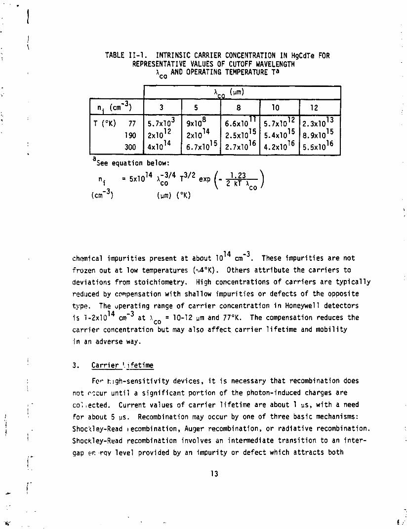
TABLE 11-1 . INTRINSIC CARRIER CONCENTRATION IN HgCdTe FOR REPRESENTATIVE VALUES OF CUTOFF WAVELENGTH
ICO AND OPERATING TEMPERATURE Ta
a See equat ion below:
chemical impur i t i es present a t about 1014 These impur i t i es a re n o t
f rozen out a t low temperatures ( d ° K ) . Others a t t r i b u t e the c a r r i e r s t o
dev ia t ions from stoichiometry. High concentrat ions o f c a r r i e r s a re t y p i c a l l y
reduced by compensation w i t h shallow i m p u r i t i e s o r defects of the opposite
type. The upera t ing range of c a r r i e r concentrat ion i n Honeywell detectors
i s 1 - 2 x 1 0 ' ~ a t lo = 10-12 urn and 7 7 O K . The compensation reduces the
c a r r i e r concentrat ion bu t may a l so a f f e c t c a r r i e r l i f e t i m e and m o b i l i t y
,in an adverse way.
Fcr k I gh-sensi t i v i t y devices , i t i s necessary t h a t recombination does
no t c x u r u n t i l a s i g n i f i c a n t p o r t i o n o f t he photon-induced charges a re
co: ,ected. Current values of c a r r i e r l i f e t i m e a re about 1 ps, w i t h a need
f o r about 5 us. Recombination may occur by one o f th ree basic mechanisms:
Shock1 ey-Read t ecombi nat ion, Auger recombination, o r r a d i a t i v e recombination.
Shockley-Read recombination involves an in termediate t r a n s i t i o n t o an i n t e r -
gap ec ;rqv l e v e l provided by an impur i t y o r de fec t which a t t r a c t s both
an e lec t ron and a hole. The l i f e t i m i s inverse ly r e l a t e d t o the number
of such l e v e l s and t o t h e i r p o s i t i o n i n the energy gap. This mechanism i s
dominant i n mater ia ls w i t h considerable impur i t ies , i n p-type mater ia l , and
a t very low temperatures, Auger recombination involves the i n t e r a c t i o n o f
a t h i r d c a r r i e r (usua l ly an e lec t ron) w i t h the recombining e lectron-hole
p a i r t o absorb the energy and junp t o a higher l e v e l i n the conduction band
continuum. This i s fo l lowed by an immediate cascade t o a lower l e v e l w i t h
the c reat ion of l a t t i c e energy (phonons). The l i f e t i m e f o r t h i s process i s 2 inverse ly re la ted t o the product of n p, where n i s the e lec t ron concentra-
t i o n and p the hole concentration. This mechanism i s dominant i n n-type
mater ia l . Radiat ive recombination involves the d i r e c t recombination of an
e lectron-hole p a i r w i t k the emission o f a photon. This mechanism gives a
l i f e t i m e inverse ly re la ted t o the np product and dominates i n near ly
i n t r i n s i c mater ia l a t very low temperatures.
4. Car r i e r M o b i l i t y
A t high temperatures, the m o b i l i t y of the c a r r i e r s i s l i m i t e d by
l a t t i c e sca t te r i ng (phonon in te rac t i ons ) . A t lower temperatures, mobi 1 i t y
i s diminished by the presence o f ionized impur i t ies . I n photoconductors,
a h igh m o b i l i t y r a t i o o f e lectrons t o holes i s desired fo r h igh gain w i t h
a low ove ra l l m o b i l i t y t o prevent impact i on i za t i on .
5. Frequency Response
A wide frequency bandwidth i s des i rab le for detectors using lase r
heterodyning and f o r o p t i c a l comnunications. A bandwidth of 2 G H z has been
achieved and a desi red goal i s about 5 GHz. Large bandwidths requ i re shor t
c a r r i e r l i fe t imes, and detectors must be designed t o have low capacitance
values t o minimize the RC t ime constant o f the c i r c u i t . The present l i m i t a -
t i o n t o 2 GHz i s no t f u l l y understood.
6. D is locat ion Density
People t y p i c a l l y express a des i re t o lower the d i s l o c a t i o n densi ty . However, w i t h opera t in devices having minor type d i s loca t ion dens i t i es
3 9 ranging f r o m 10 t o 10 cmWZ, there seems t o be no c lea r c o r r e l a t i o n
po in t i ng t o t h i s as a source o f degradation i n device perfonance. 14
7. guenchIAnnea1 Processinq
Honeywell has had success w i t h growing large HgCdTe c rys ta ls
(112 x 4 inches) by a quenchlanneal process. The quenching pa r t provides an overa l l macroscopic composi t i onal uni formity. The h i gh-temperature
anneal promotes the growth o f a s ing le c rys ta l . I n t h i s process, CdTe
microprecipi tates and Hg occlusions are swept out. Material w i t h lower
values of x ( long wavelength cu to f f ) are easier t o produce be~ause of the
fas te r d i f f us i on o f Hg. Stoichiometry i s adjusted i n wafers by control1 ing
the mercury vapor pressure during the annealing process. The e n t i r e process
takes 6 t o 10 weeks.
8. L i qu id Phase Epitaxy
Researchers a t Honeywell , Rockwell , and Lincoln Labs have indicated
success w i th horizontal LPE on CdTe o r CdTeSe substrates from a te l lu r ium-
r i c h solut ion. This method, using an open tube s l i d e r approach, produces
a uniformly t h i ck layer w i t h compositional var iat ions kept t o w i t h i n a 2 few percent over areas on the order o f 1 cm . This method may be used t o
produce mu1 t i - layer structures.
9. Prognosis
There are r e a l l y two divergent opinions concerning the present s ta te
o f the a r t . Suppliers o f devices are general ly op t im is t i c and do not admit
any insurmountable problems i n achieving theore t i ca l l y 1 imi ted performance.
They t yp i ca l l y be1 ieve tha t fu r the r refinements of t h e i r apparatus can
increase the y i e l d of h igh-qual i ty devices. Users, on the other hand, are
not sat is f ied w i t h the nonuniform responses present i n the small arrays
( t y p i c a l l y 32 x 32 elements) cur rent ly avai lable and are skeptical about achieving desirable resul t s for larger (1,000 x 1,000 elements) arrays.
The present detector arrays i n operation are usual ly photoconductive (PC)
and employ e i the r software or hardware to compensate f o r i r r e g u l a r i t i e s .
A frequently used technique i s tha t of time delay and in tegrat ion (TDI),
which mechanically scans an image over several array elements and averages
the signal output. The large arrays of the future w i l l need t o operate i n
a s ta r ing mode w i t h a one-to-one correspondence between source and image.
The presence o f hardware c i r c u i t r y f o r image enhancement would be unmanage-
able for m i l 1 ion element arrays, as would be computer software compensation.
A t l eas t f o r the smaller arrays, the large var ia t ions o f response (as
much as 50 percent) are less due t o gross compositional differences (kept
t o about 1 percent) than t o microscopic var ia t ions of defects and/or
impurit ies. These ex t r i ns i c factors give r i s e t o a higher noise leve l
from increased ambient c a r r i e r concentration and decreased c a r r i e r l i f e t ime .
It i s extremely important t o i s o l a t e and el iminate these ex t r i ns i c factors.
Presently, i t i s not establ ished whether o r not some of these degrading
elements are introduced i n the bulk processing o f the material or i n the
device fabr icat ion.
B. PRESENTATION FORMAT
I n conducting t h i s study on the u t i l i t y o f space processing experi-
ments i n the production o f high-qua1 i t y in f ra red detector crystals, i t was
recognized a t the s t a r t t ha t any successful program of sol i c i t i n g the
pa r t i c i pa t i on of agencies outside of NASA would depend on the judgments o f
three types of people. One, the sc i en t i s t would have t o recognize a physi-
cal ra t iona le f o r expecting the space environment t o provide tangible
benefi ts. Two, the engineer would have t o be convinced t ha t equipment
could be fabricated t o properly exp lo i t the advantages of the space environ-
ment without y i e l d i ng t o any disadvantages. Three, the program manager
must have s u f f i c i e n t information t o evaluate the r i s k s and benefits i n
t e n s of the time and money spent on a space processing venture as opposed
t o other more conventional programs. A successful presentat ion must there-
fore be di rected towards representatives of a l l three classes. A major
problem i s t o devise a presentation t ha t would, i n a short time, simul tan-
eously st imulate the i n te res t of members of these three groups. The prime
target i n the audience i s , o f course, tha t ind iv idua l who cont ro ls the
d i rec t ion and/or funding o f research efforts.
The formal presentation should be kept t o a r e l a t i v e l y simple leve l t o
be understandable t o a l l three groups. Any technical discussion should be
i n risponse t o questions from the audience. I n some instances, i t may be
expeca.ed tha t members o f any one of the three groups may have only a l i m i t e d
knowledge o f the other groups' f ie lds. A discussion of the fundamentals of
both the detector and mater ia ls processing physics would be sui table.
Chapter I 1 1 presents a f a i r l y thorough treatment o f the theory o f I R
d e t e c ~ i o n and points out those asfects o f a mater ia l t ha t w i l l enhance o r
degrade detector performance. Chapter I V i s a less deta i led overview o f
the subject o f c rys ta l growth. It i s meant t o provide a framework f o r a
presentation t o an audience tha t i s not wel l versed i n tha t subject. Both
of these chapters, along w i t h provid ing guidance f o r any presentation, may
also be d is t r ibu ted as informational mater ia l . A l i s t o f the per t inent
publacations consulted i n generating Cha;ters I11 and I V i s provided a t
the end o f the report. Chapter V evaluates the present NASA and m i l i t a r y
programs i n I R detector mater ia ls and makes recomnendations f o r NASA considerat i on.
I I I. DETECTOR MATERIALS SCIENCE
A. INTRODUCTION
The goals of this chapter are:
a Provide a comnon base of information on detector materials science t h a t can be communicated efficiently t o a diverse audience containing program managers, appl i ca t ion engineers, and materials scientists.
e Prepare a framework for integration of data on many different ma teri a1 s and physical processes.
In order t o attain these goals, the following three basic questions are addressed:
e What materials are useful for infrared detectors? a How can one gauge the difference between actual and potential
detector performance? How does materi a1 structure affect detector performance?
B. DETECTOR
Since the semiconductor's electronic bandgap determines the minimum photon energy or maximum wavelength to which the detector i s sensitive, various materials provide detection capabilities i n different portions of the infrared spectrum. Furthermore, the detection response is not the same for all radiation of a wavelength less t h a n the maximum; the response generally increases w i t h increasing w?,velength and peaks a t a wavelength slightly shorter than the maximum.
In order t o minimize ~ttenuation due t o atmospheric absorption and scattering, dutectcrs are often designed t o operate in the middle infrared region between 3 and 5 pm or i n the thermal infrared between 8 and 14 urn.
These windows are not completely transparent: there i s , for example, a major decrease in transmi ttance a t 9.5 pm due t o ozone.
18
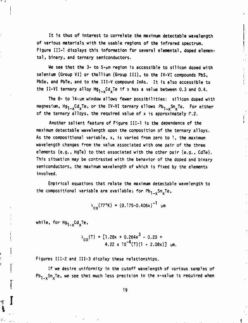
It i s thus of i n t e r e s t t o co r re la te the maximum detectable wavelength
of various mater ia ls w i t h the usable regions of the i n f ra red spectrum.
Figure 111-1 d isp lays t h i s information fo r several elemental, doped elemen-
t a l , binary, and ternary semiconductors.
We see t h a t the 3- t o 5-pm region i s accessible t o s i l i con doped w i t h
selenium (Group VI ) o r t h a l l i u m (Group 111), t o the I V - V I compounds PbS,
PbSe, and PbTe, and t o the 111-V compound InAs. It i s a l so accessible t o the 11-VI ternary a l l o y Hgl-,CdxTe if x has a value between 0.5 and 0.4.
The 8- t o 14-pm window al lows fewer p o s s i b i l i t i e s : s i l icon doped w i t h
magnesiumB Hgl -xCdxTe, o r the I V - V I ternary a1 lows Pbl -,SnxTe. For e i t h e r o f the ternary a l l oys , the required value of x i s approximately C.2.
Another s a l i e n t feature of F igure 111-1 i s the dependence of the
maximum detectable wavelength upon the composition of the te rnary a1 loys.
As the compositional var iable, x, i s var ied from zero t o 1, the maximum
wavelength changes f r o m the value associated w i t h one p a i r o f the th ree
elements (e.g., HgTe) t o t h a t associated w i t h the other p a i r (e.g., CdTe).
This s i t u a t i o n may be contrasted w i t h the behavior of t he doped and b inary
semiconductors, the maximum wavelength of which i s f i x e d by the elements
involved.
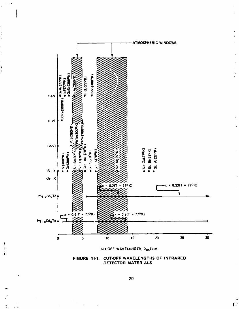
Empir ical equations t h a t r e l a t e the maximum detectable wavelength t o
the compositional var iab le are ava i lab le ; f o r Pbl -,SnXTe,
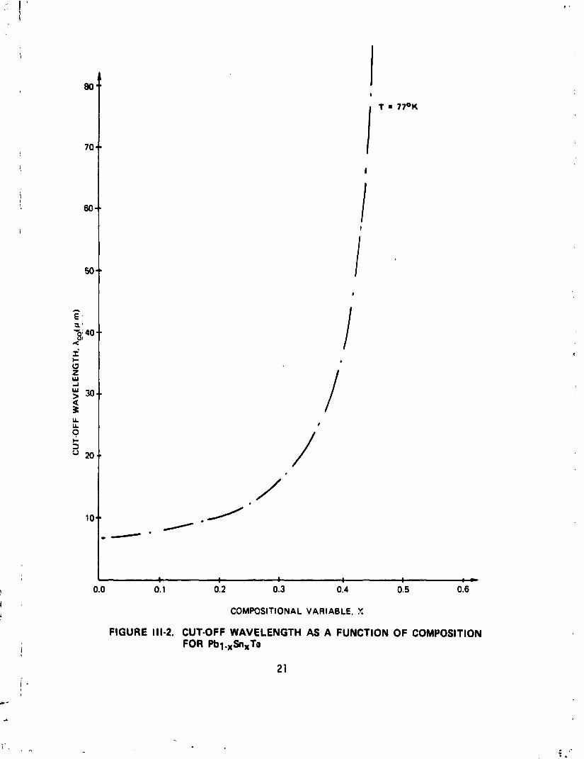
whi le. f o r Hgl-,CdXTe,
Figures 111-2 and 111-3 d isp lay these re la t ionsh ips .
If we des i re uni formi ty i n the cutoff wavelength of various samples o f
Pbl-xSnxTe, we see t h a t much less prec is ion i n the x-value i s requ i red when
cATMOIHERIC WINDOWS
Si: X
Ge: X
CUT-OFF WAVELC:dGTH, \,( ~t ml
FIGURE Ill-1. CUT-OFF WAVELENGTHS OF INFRARED DETECTOR MATERIALS
COMPOSlf IONAL VARIABLE. X
FIGURE 111-2. CUT-OFF WAVELENGTH AS A FUNCTION OF COMPOSITION FOR Pbl.,Sn,Ta
1 I 1 1 I d .O 0.1 0.2 0.3 0.4 0.5 0.6
COMPOSITIONAL VARIABLC, X
FIGURE 111-3. CUT-OFF WAVELENGTH AS A FUNCTION OF COMPOSITION FOR Hgl.rCdxTe
l c o i s less than 18 rm. If Ace must l i e between 10 and 11 um, x may vary
by about 10 percent from 0.19 t o 0.21. However, i f Aco must 1 i e between
30 and 31 urn, then x may vary only by about 1 percent from 0.349 t o 0.352.
Simi lar uniformity i n Hgl - ,CdXTe requires less precis ion i n the x-value
when a,, i s less than 5 pm. A t an operating temperature of 77OK, i f A must CO
1 i e between 3 and 4 pm, then x may vary by about 17 percent from 0.397 t o
0.335. However, if Aco must l i e between 10 and 11 h, then x nay vary only
by about 3 percent from 0.217 t o 0.211.
C. MODES OF "€VICE OPERATION
There are two p r inc ipa l ways t o u t i l i z e semiconductors as photon detec-
to rs i n the in f rared por t ion o f the spectrum. I n the f i r s t , the mater ia l
serves as a photoconductor; i n the second, i t serves as a photodiode.
The phenomenon o f photoconductivity i s based on the in te rna l photo-
e l ec t r i c effect: l i g h t quanta exc i te charge ca r r i e r s ins ide the material,
thus a1 t e r i ng the material ' s e l ec t r i ca l propert ies. Pure semiconductors
are known as i n t r i n s i c photoconductors, since quanta exc i te electrons across
the bandgap from the valence band t o the conduction band. Doped semiconduc-
tors are known as ex t r i ns i c photoconductors since energy leve ls created by an
impurity ins ide the bandgap are involved i n acceptance o f an electron from
the valence band o r donation o f an electron t o the conduction band.
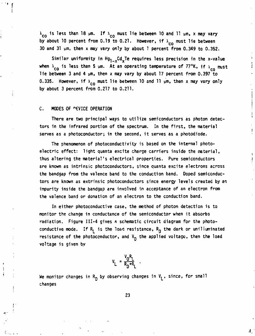
I n e i t he r photoconductive case, the method of photon detect ion i s t o
monitor the change i n conductance o f the semiconductor when i t absorbs
radiat ion. Figure 111-4 gives a schematic c i r c u i t diagram for the photo-
conductive mode. I f RL i s the 1050 resistance, RD the dark o r unil iuminated
resistance o f the photoccnductor, and Yo the appl ied voltage, then the load
voltage i s given b.v
We monitor changes i n RD by observing changes i n VL, since, f o r small
changes
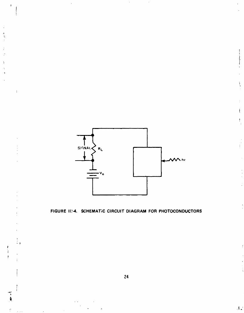
FIGURE 11!4. SCHEMATiC CIRCUIT DIAGRAM FOR PHOTOCONDUCTORS
The simplest semiconductor photodiode i s constructed from two types o f
material: one r i c h i n electrons (n-type) and one r i c h i n holes (p-type).
Juxtaposit ion of these two types creates a junct ion region i n which there
i s a strong e l e c t r i c f i e l d po in t ing from the n-type t o the p-type mater ia l .
When rad ia t ion i s absorbed i n the junct ion region, electrons may be exci ted
i n t o the conduction band from the valence band; the loca l e l e c t r i c f i e l d
w i l l separate the electron-hole p a i r thus created and give r i s e t o a measur-
able current. Monitoring t h i s current al lows one t o detect radiat ion.
Figure 111-5 gives a schematic diagram of a p-n semiconductor photodiode.
The i c t e r f ac i a l zone i n a junct ion photodiode i s often labe l led the
deplet ion layer since the density o f f r ee charge ca r r i e r s i s very low i n
t h i s region. The width of t h i s region can be cont ro l l ed by the voltage
appl ied across the photodiode. If the p-typo side i s maintained a t a
higher potent ia l than the n-type side, the device i s said t o be reverse-
biased and the width o f the deplet ion layer i s increased. This means t ha t
more electrons exci ted by incident rad ia t ion w i l l be close t o the junct ion
region; t h i s w i 11 increase the photocurrent and improve sens i t i v i t y .
Increasing the width o f the deplet ion layer reduces i t s capacitance; t h i s
decreases the RC time constant o f the photodiode c i r c u i t and therefore
l3wers i t s response time.
One may increase the width o f the deplet ion layer s t i l l fur ther by
separating the p-region f rom the n-region w i t h a layer o f i n t r i n s i c mate-
r i a l . This r e l a t i v e l y wide, undoped layer increases the s e n s i t i v i t y and
decreases the response time under reverse-bias conditions. This s t ruc ture
i s known as a p-i-n photodiode.
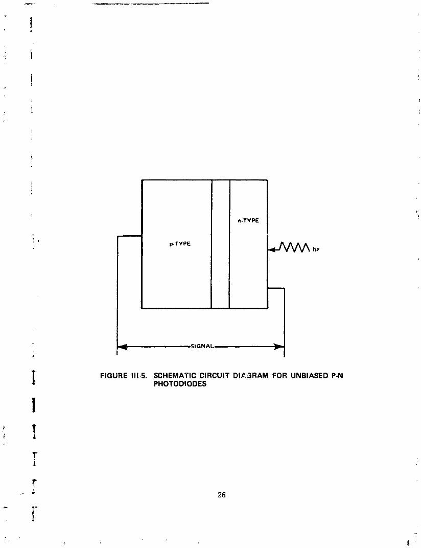
FIGURE 111-5. SCHEMATIC CIRCUIT DIC.3RAM FOR UNBIASED P-N PHOTODIODES
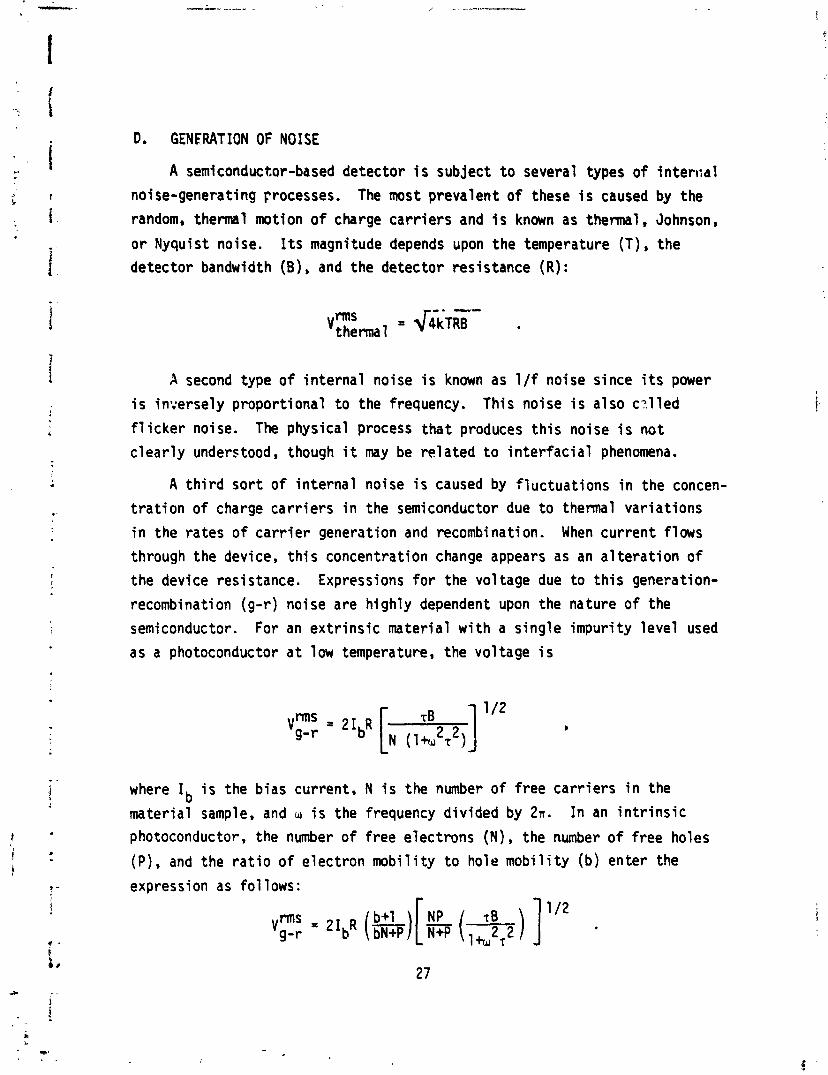
D. GENERATION OF NOISE
A semiconductor-based detector i s subject t o several types o f in ten id1
noise-generating Frocesses. The most prevalent of these i s caused by the
random, thermal motion of charge ca r r i e r s and i s known as thermal, Johnson,
o r Nyquist noise. I t s magnitude depends upon the temperature (T) , the detector bandwidth (B) , and the detector resistance (R) :
rms 'thermal = < i k ~ E -
A second type o f i n te rna l noise i s known as 1 /f noise since i t s power
i s in7;ersely proport ional t o the frequency. This noise i s a lso ca.l led
f l i c k e r noise. The physical process t ha t produces t h i s noise i s no t
c l ea r l y understood, though i t may be re la ted t o in te r fac ia l phenomena.
A t h i r d so r t o f i n te rna l noise i s caused by f luc tuat ions i n the concen-
t r a t i o n o f charge ca r r i e r s i n the semiconductor due t o thermal var iat ions
i n the rates o f c a r r i e r generation and recombination. When current f lows
through the device, t h i s concentration change appears as an a l t e ra t i on o f
the device resistance. Expressions for the voltage due t o t h i s generation-
recombination (9- r ) noise are highly dependent upon the nature o f the
semiconductor. For an ex t r i ns i c material w i t h a s ing le impur i ty leve l used
as a photoconductor a t low temperature, the voltage i s
where Ib i s the bias current, N i s the number of f ree ca r r ie rs i n the
material sample, and u i s the frequency div ided by 2 ~ . I n an i n t r i n s i c
photoconductor, the number of free electrons (N) , the number of free holes
(P), and the r a t i o o f e lectron mob i l i t y t o hole mob i l i t y (b) enter the
expression as fo1 lows:
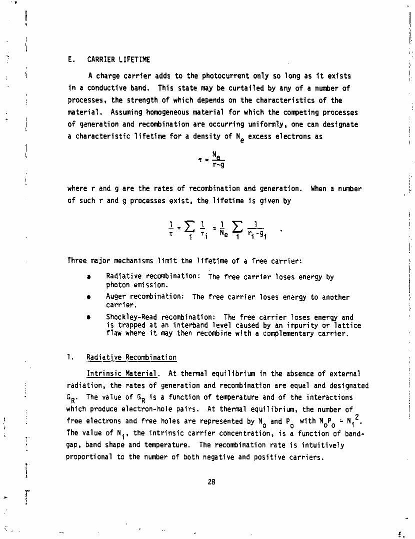
E. CARRIER LIFETIME
A charge c a r r i e r adds t o the photocurrent only so long as i t ex is ts
i n a conductive band. This s ta te may be cu r t a i l ed by any o f a number o f
processes, the strength of which depends on the character is t ics o f the
material. Assuming homogeneous material fo r which the competing processes
o f qsnerati on and recombination are occurr ing uniformly , one can designate
a character is t ic l i f e t i m e f o r a density of N, excess electrons as
where r and g are the rates o f recombination and generation. When a number
of such r and g processes ex is t , the l i f e t ime i s given by
Three major mechanisms l i m i t the l i f e t i m e o f a free ca r r i e r :
Radiat ive recombination: The f ree c a r r i e r loses energy by photon emi ssi on.
a Auger recombination: The f ree c a r r i e r loses en2rgy t o another ca r r i e r .
a Shoc k l ey-Read recombination : The free c a r r i e r 1 oses energy and i s trapped a t an interband leve l caused by an impur i ty o r l a t t i c e f law where i t may then recombine w i t h a complementary ca r r ie r .
1. Radiative Recombination
I n t r i n s i c Material. A t thermal equi 1 i b r i urn i n the absence o f external
radiat ion, the rates o f generation and recombination are equal and designated
GR. The value o f GR i s a funct ion of temperature and of the in teract ions
which produce electron-hole pairs. A t thermal equi 1 ibrium, the number o f 2 f ree electrons and f ree holes are represented by No and Po w i t h NoPo Ni .
The value of Ni, the i n t r i n s i c ca r r i e r concentration, i s a function o f band-
gap, band shape and temperature. The recombination ra te i s i n t u i t i v e l y
proport ional t o the number of both negative and pos i t i ve car r iers .
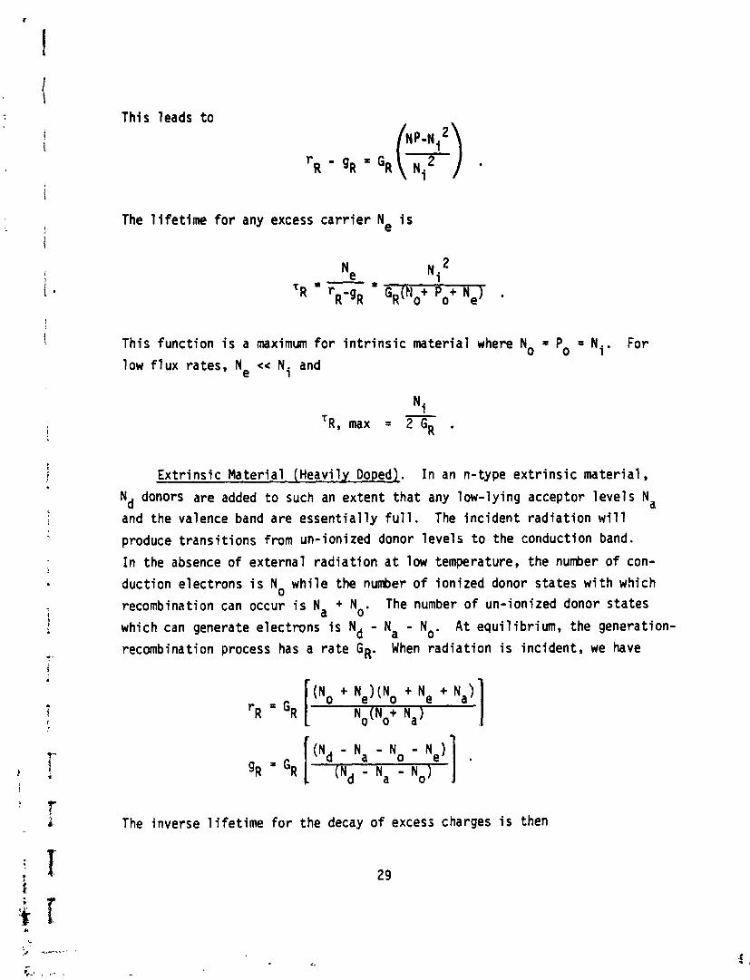
This leads t o
The l i f e t i m e f o r any excess c a r r i e r Ne i s
This funct ion i s a maximum f o r i n t r i n s i c mater ia l where No = Po = Ni. For low f l u x rates, Ne << Ni and
Ex t r ins ic Mater ia l (Heavily Dopedr. I n an n-type ex t r i ns i c mater ia l ,
Nd donors are added t o such an extent t ha t any low-lying acceptor leve ls Na
and the valence band are essent ia l ly f u l l . The inc ident rad ia t ion w i l l produce t rans i t i ons from un-ionized donor leve ls t o the conduction band.
I n the absence o f external rad ia t ion a t low temperature, the n u h e r of con-
duction electrons i s No whi le the nMber o f ionized donor states w i t h which
recombination can occur i s Na + No. The number o f un-ionized donor states
which can generate electrons i s Nd - Na - No. A t equi l ibr ium, the generation-
recombination process has a ra te GR. When rad ia t ion i s inc ident , we have
The inverse 1 i fe t ime f o r the decay o f excess charges i s then
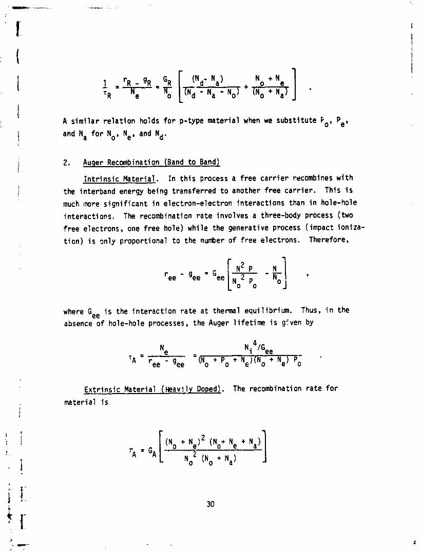
A s im i l a r r e l a t i on holds f o r p-type material when we subst i tu te Po, Pe,
and Na for No, Ne, and Nd.
2. Auger Recombination (Band t o Bandl
I n t r i n s i c Material. I n t h i s process a f ree c a r r i e r recombines w i t h
the interband energy being t ransferred t o another free ca r r ie r . This i s
much inore s i gn i f i can t i n electron-electron in teract ions than i n hole-hole
interact ions. The recombination r a t e involves a three-body process (two
f ree electrons, one f ree hole) whi le the generative process (impact i o n i za-
t i on ) i s only proport ional t o the number of f ree electrons. Therefore,
- N2 P - gee - .ee [ 2 - k] No
where Gee i s the in te rac t ion ra te a t thermal equi l ibr ium. Thus, i n the
absence o f hole-hole processes, the Auger l i f e t i m e i s gfven by
4 t e - - Ni lGee
'A - gee (N o + P o + N,)(No + Ne) Po
Ex t r ins ic Material ( k a v i ly Doped). The recombination r a t e f o r
material i s
whi le the generation r a t e i s
The inverse 1 i fe t ime i s
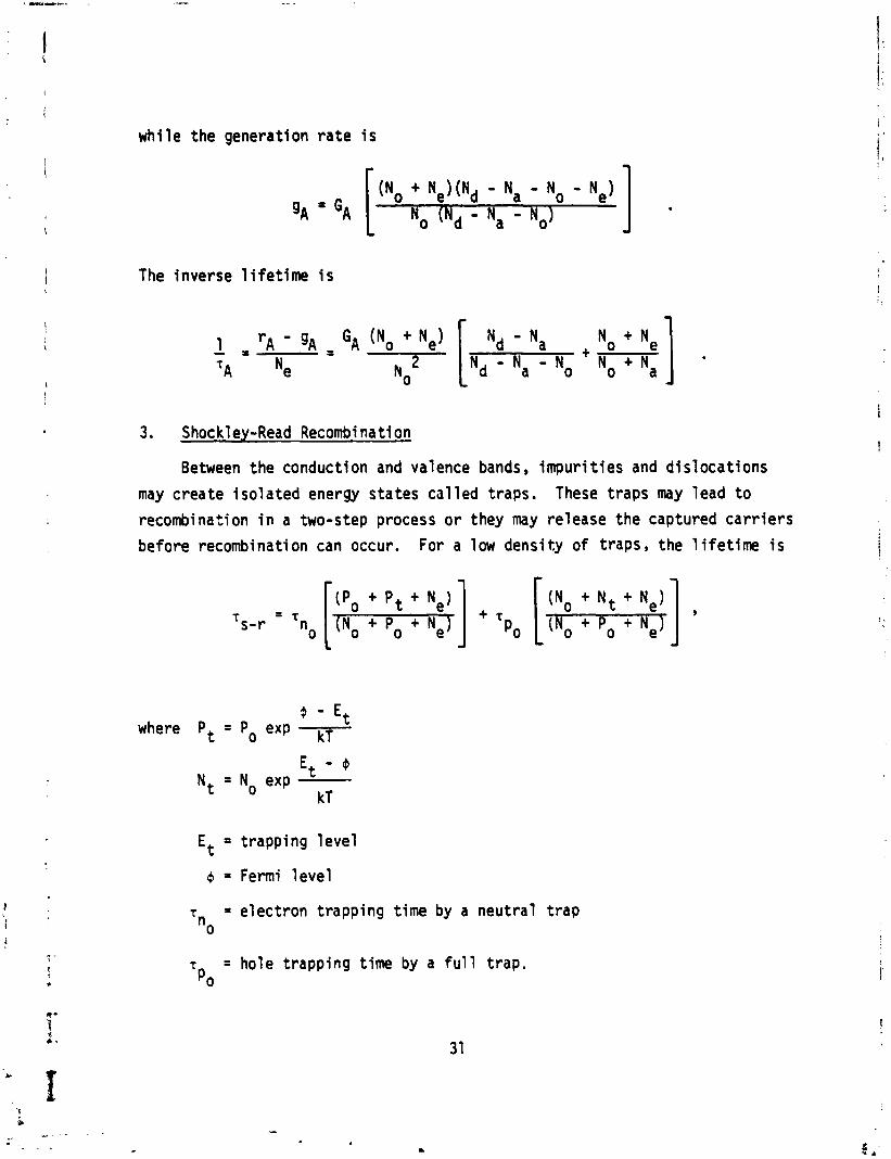
3, Shock1 ey-Read Recombi na t i on
Between the conduction and valence bands, impuri t i e s and d i s loca t ions
may create i s o l a t e d energy states c a l l e d traps. These t raps may lead t o
recombination i n a two-step process o r they may release the captured c a r r i e r s
before recombination can occur. For a low densi ty o f t raps, the l i f e t i m e i s
(Po + Pt + N e l (NO + N t + Ne) T s- r = 'no [INo + Po + Ne,] + 'p0 [(No + Po + N e l ]
d - Et where Pt = Po exp kT
Et - P Nt = No exp
kT
Et = t rapping l e v e l
Q = Fermi l e v e l
T = e lec t ron t rapping t ime by a neut ra l t r a p no
T = hole t rapp ing t ime by a f u l l t rap. Po
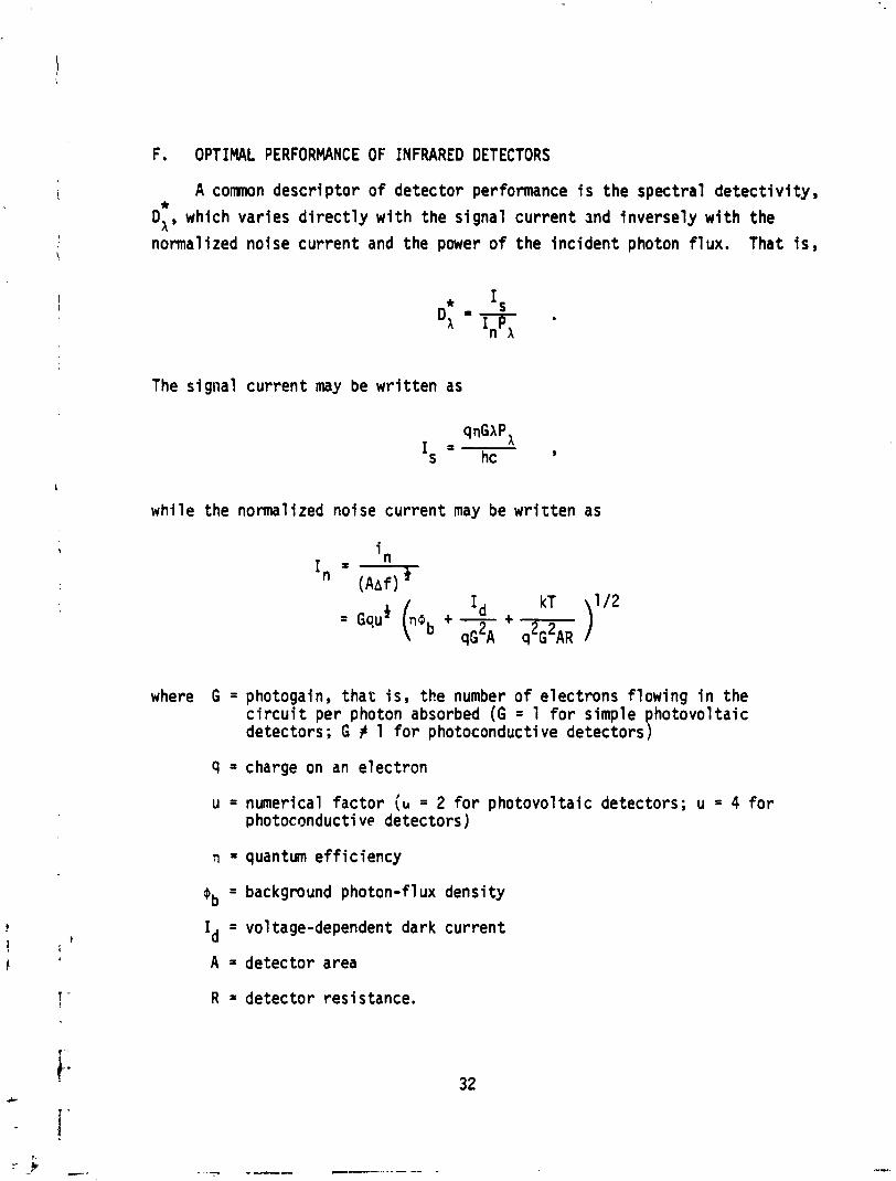
F . OPTIMAL PERFORMANCE OF INFRARED DETECTORS
A comnon descr iptor of detector performance i s the spectral de tec t i v i ty , * D A 9 which varies d i r e c t l y w i t h the signal current md inversely w i t h the normalized noise current and the power o f the inc ident photon f lux . That i s ,
The signal current may be w r i t t en as
whi le the normalized noise current may be w r i t t en as
where G = photogain, t ha t i s , the number o f electrons flowing i n the c i r c u i t per photon absorbed (G = 1 for simple photovoltaic detectors; G # 1 for photoconductive detectors)
9 = charge on an electron
u = numerical factor (b = 2 for photovol ta ic detectors; u = 4 f o r p hotoconducti ve detectors)
TI = quantum e f f i c iency
4b = background photon-fl ux density
Id = voltage-dependent dark current
A = detector area
R = detector resistance.
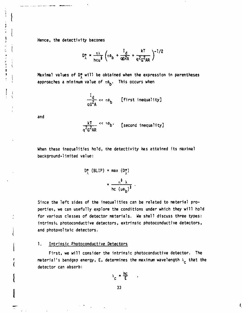
Hence, the detect1 v i t y becomes
I d D: = 3 ("b +
+ -- kT )-l'*
Maximal values of D; w i l l be obtained when the expression i n parentheses
approaches a minimum value of neb. This occurs when
Id - << rlQ b [ f i r s t inequal i ty] ~ G * A
and kT << r,Qb. [second inequal i ty]
When these i n e q u a l i t i e s hold, the d e t e c t i v i t y has a t ta ined i t s maximal
background-limited value:
0; (BLIP) = max (D;)
Since the l e f t sides of the i n e q u a l i t i e s can be r e l a t e d t o mater ia l pro-
per t ies , we can usefu l ly explore the condi t ions under which they w i l l ho ld
f o r various classes o f de tec tor mater ia ls . We s h a l l discuss three types:
i n t r i n s i c photoconductive detectors, e x t r i n s i c photoconductive detectors,
and photovol t a i c detectors.
1. I n t r i n s i c Photoconductive Detectors
F i r s t , we w i 11 consider the i n t r i n s i c photoconductive detector. The
mate r ia l ' s bandgap energy, E, determines the maximum wavelength 1 t h a t the
detector can absorb: hc
'c 'T
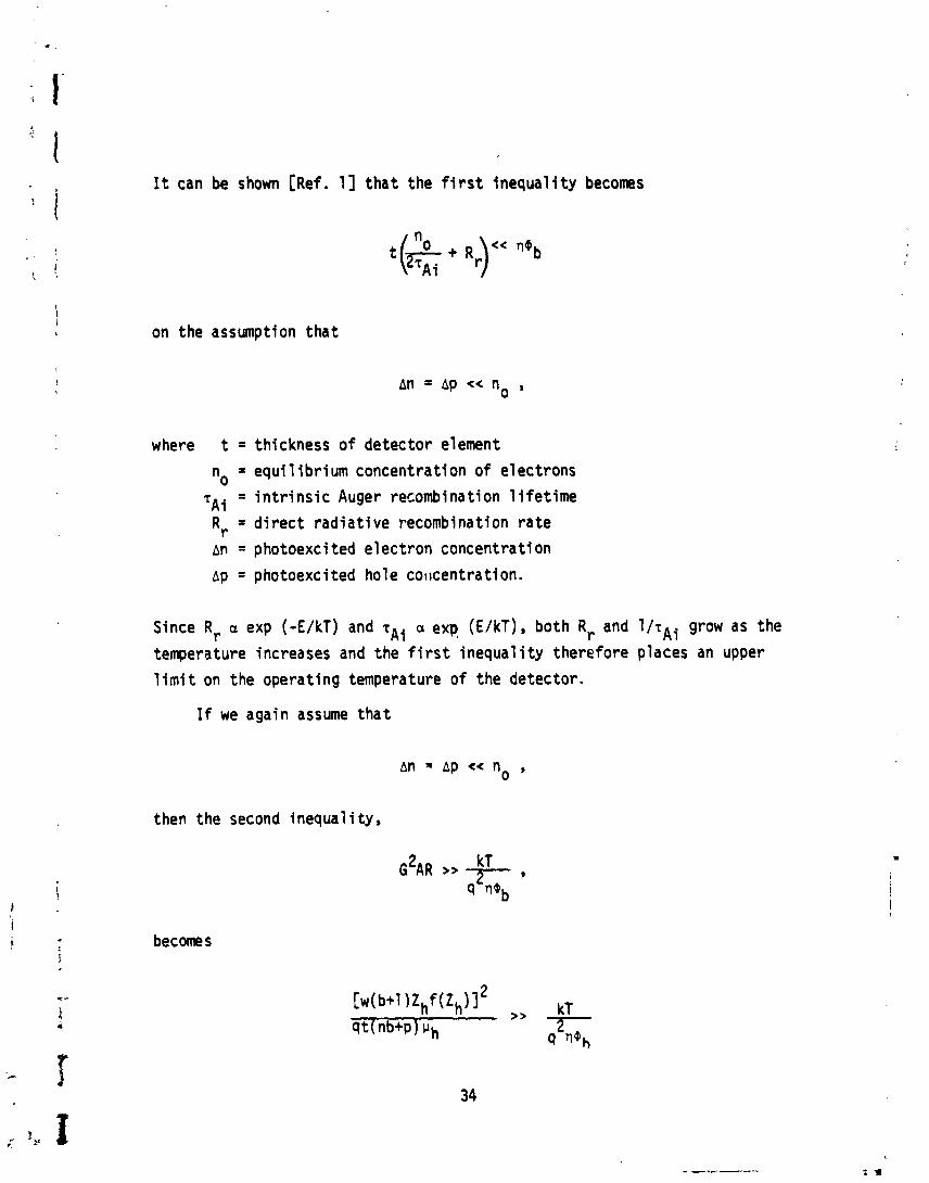
It can be shown [Ref, I] tha t the f i r s t inequal i ty becomes
on the assumption tha t
where t = thickness of detector element
n = equi 1 i b r i urn concentration o f electrons 0
'Ai = i n t r i n s i c Auger recombination l i f e t i m e
Rr = d i r ec t rad ia t i ve recombination r a t e
An = photoexci ted electron concentration
~p = photoexcited hole coltcentration.
Since Rr a exp (-E/kT) and rAi a exp (E/kT), both Rr and l/rAi grow as the
temperature increases and the f i r s t inequal i ty therefore places an upper
1 i m i t on the operating temperature o f the detector.
If we again assume tha t
then the second inequal i ty,
becomes
f o r n-type i n t r i n s i c photoconductors and
f o r p-type i n t r i n s i c photoconductors.
Note t ha t Zh = ph~hEelw
'e = "ereEe/w 1 f (Z) = 1 [1-exp ( -
w = length o r width of square detector element
b = V,/V~
" e = e lectron mob i l i t y
"h = hole mob i l i t y
t = electron l i f e t i m e e
h = hole l i f e t ime
n = e lectron concentration
p = hole concentration
Ee = e l e c t r i c f i e l d appl ied across detector element.
I n terns o f rAi and Rr, Zh becomes
where ni = i n t r i n s i c c a r r i e r concentrat ion
P = e l e c t r i c a l power d iss ipa ted i n detector .
Background-1 i m i ted performance can thus be achieved w i t h mater ia l s and
devices t h a t s a t i s f y t h i s second i n e q u a l i t y a t temperatures consistent w i t h
s a t i s f a c t l o n of the f i r s t inequa l i ty .
2. E x t r i n s i c Photoconduc~ve Detectors
I n t h i s case, the dopant i o n i z a t i o n energy, Ed, determines tC c u t o f f
wavelength, lc
Th2 f i r s t i nequa l i t y becomes
N Ed B(Nd-N,)t 1 exp ( - R ) cc 11,
9c b ,
where B = recombination coef f i c ien t
Nd = donor concentrat i dn
Na = acceptor concentrat ion
Nc = conducti on-band dens i ty of s tates
c = generation r a t e of c a r r i e r s i n conduction band.
Since the l e f t s ids o f t h i s i nequa l i t y grows exponent ia l l y as the tempe~a-
t u r e increases, we can determine an upper bound fw the operat ing temperature
of the detector .
For an n-type e x t r i n s i c photoconductor, we assume t h a t
so that
and
Then the second i nequal i ty becomes
where
If a device can be constructed such that G , w , N e , and T, satisfy this i~equal i t y a t a temperature less than or equal t o the mximum temperature determined by the f i r s t inequality, then background-1 imi ted performance can be achieved.
3. Photovol taic Detectors
For photovoltaic detectors, the dark current i s expressed as
where V i s the appl :ed voltage and fl i s a numerical factor which depends upon the nature af the material junction in the detector. For a Schottky barrier, 6 = 1; for a p-n junction, 1 S 8 < 2. The photovoltaic gain i s 1 ,
and the f i r s t inequality becomes 3 7
kT - q v exp << nab q 2 ~ ~
-q v sRA exp kT B >> 7- .
4b
The second inequal i ty becomes
We see tha t both inequa l i t i es require the maximization o f RA. The work o f
Melogai 1 i s and aha an [Ref. 21 and Long [Ref. 11 has shown tha t the maximum +
value o f RA f o r a p-n junct ion i s obtained when a p -p, metal-semiconductor
back contact i s used. Then
~ T P max (RAI = & ,
q Bni
where P = equi l ibr ium hole concentration i n the p-type region PO
"i = i n t r i n s i c ca r r i e r concentration
i3 = distance from p-n junct ion t o the back contact.
This maximum value assumes t ha t B i s much smaller than the ca r r i e r dif fusion
lefigth. The two i n e q u a l i t i e ~ thus become
and
Background-1 i m i t ed performatice can be obta . ' d when inaterial and device character is t ics sat is fy these inequal i t ies.
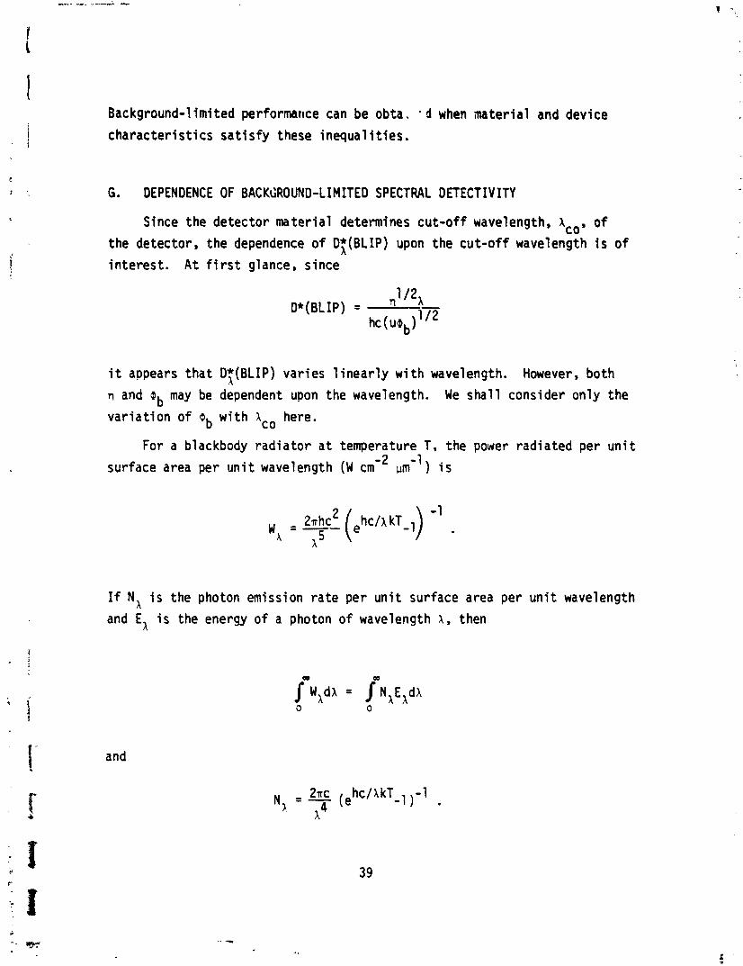
G . DEPENDENCE OF BACKGROUND-LIMITED SPECTRAL DETECTIVITY
Since the detector mater ia l determines cut-off wavelength, \o, o f
the detector, the dependence of Df (BLIP) upon the cut-of f wavelength i s o f
in terest . A t f i r s t glance, since
i t appears tha t D;(BLIP) varies 1 inear l y w i t h wavelength. However, both TI and -ab may be dependent upon the wavelength. We sha l l consider only the
va r ia t ion o f ob w i t h Ac0 here.
For a blackbody rad ia to r a t temperature T, the power radiated per u n i t
surface area per u n i t wavelength ( W m ) i s
If N, i s the photon emission ra te per u n i t surface area per u n i t wavelength
and El i s the energy of a photon of wavelength A , then
1 - and
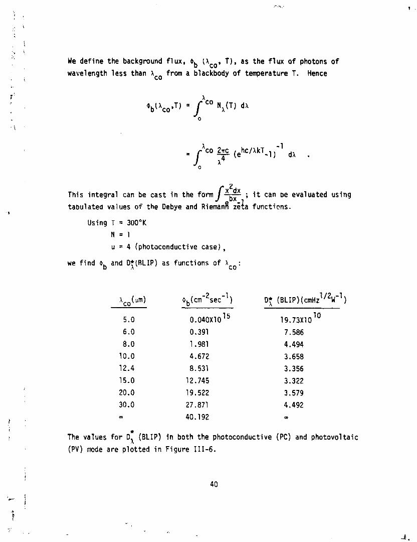
We define the background f lux. @b (Aco. T) , as the f lux of photons o f
wavelength less than lo from a blackbody of temperature T. Hence
@bl 'co ,TI = jc0 N'(T) dA
2 This in tegra l can be cast i n the form /* ; i t can ae evaluated using
t a ~ v l a t e d values of the Debye and ~iemanfi d l a functicns.
Using T = 300°K
N = l
u = 4 (photoconductive case) ,
we f ind m b and D;[RLIP) as functions o f Ace :
-2 -1 A,, (urn) ob(cm sec ) D: (BLIP) (cmHz 1 /2N-1 )
The values f o r 0; (BLIP) fn both the photoconductive (PC) and photovol ta ic
(PV) mode are p lo t ted i n Figure 111-6.
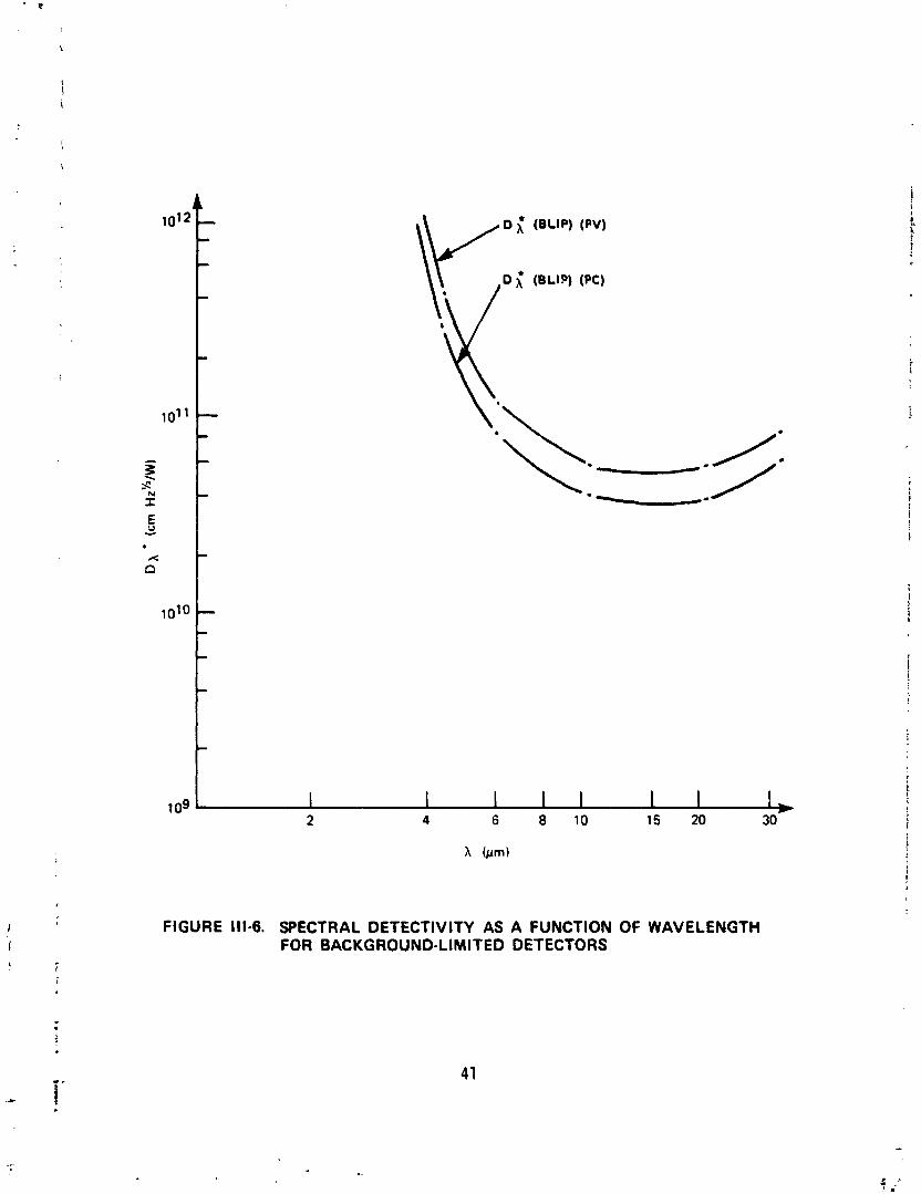
FIGURE 111-6. SPECTRAL DETECTlVlTY AS A FUNCTION OF WAVELENGTH FOR BACKGROUND-LIMITED DETECTORS
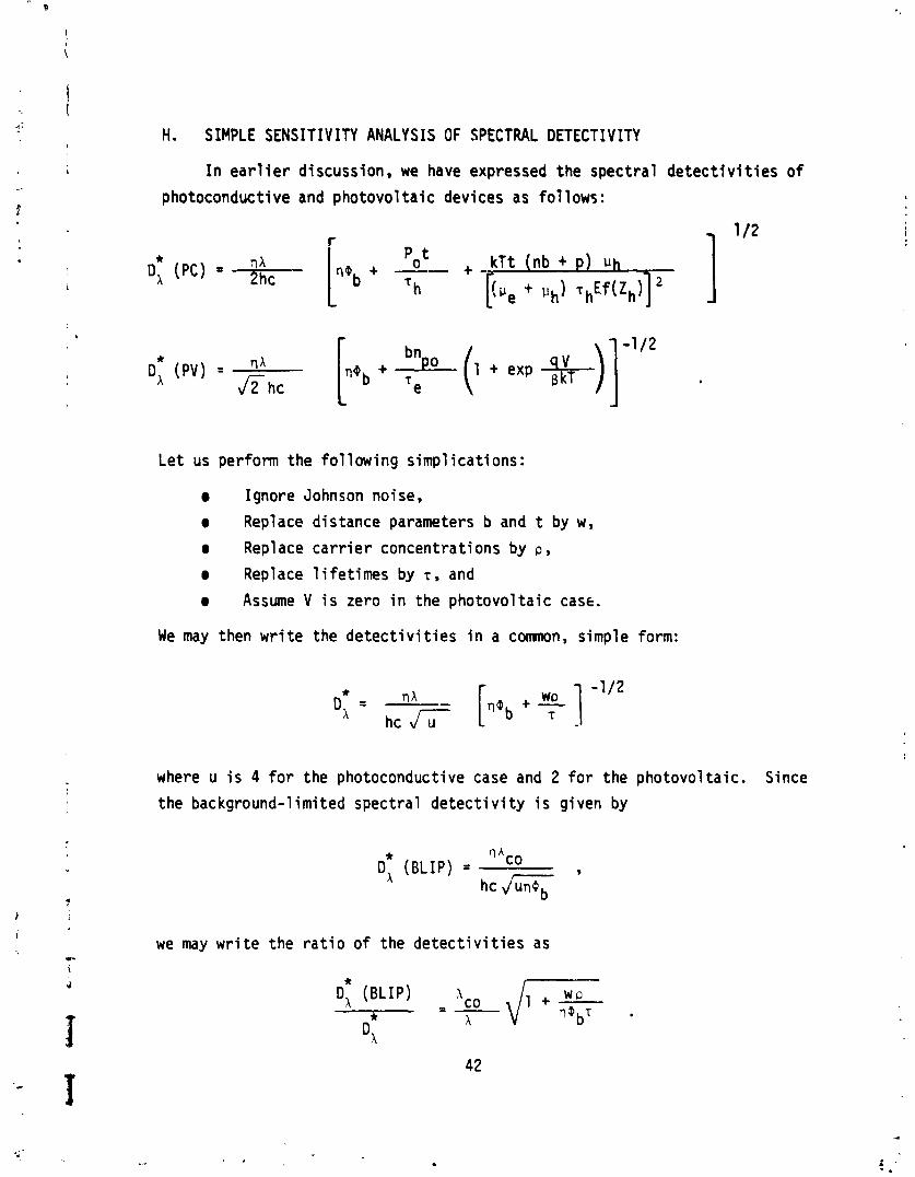
H . SIMPLE SENSITIVITY ANALYSIS OF SPECTRAL DETECTIV ITY
I n e a r l i e r discussion, we have expressed the spectra l d e t e c t i v i t i e s o f
photoconductive and p hotovol t a i c devices as f o l 1 ows :
Le t us perform the fo l lowing s impl icat ions:
m Ignore Johnson noise,
m Replace distance parameters b and t by w,
a Replace c a r r i e r concentrat ions by p ,
Replace l i f e t imes by t, and
a Assume V i s zero i n the photovo l ta ic case.
We may then w r i t e the d e t e c t i v i t i e s i n a comnon, simple form:
where u i s 4 f o r the photoconductive case and 2 f o r the photovol ta ic . Since
the background-1 im i ted spectra l d e t e c t i v i t y i s given by
0: (BLIP) = OAc0 - 9
we may w r i t e the r a t i o of the d e t e c t i v i t i e s as
D; (BLIP) x = - * c0 . X
1
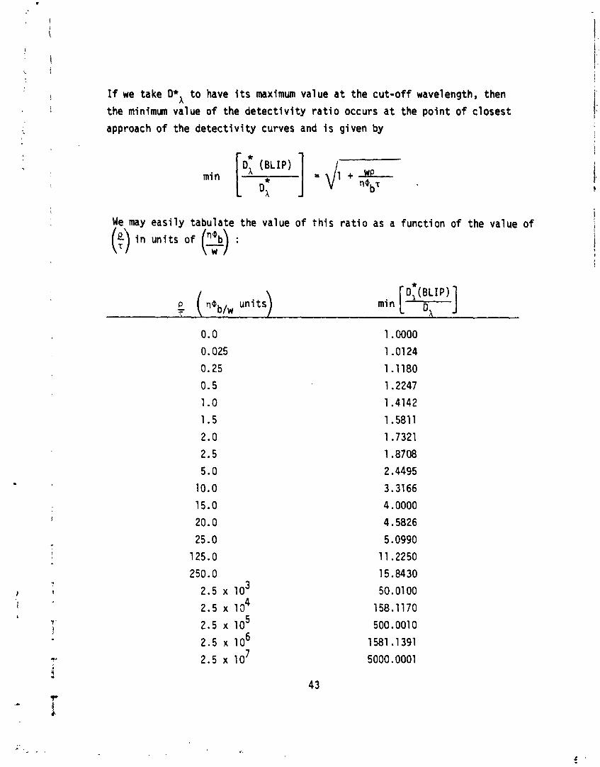
If we take D*A t o have i t s maximum value a t the cu t - o f f wavelength, then
the minimum value of the d e t e c t i v i t y r a t i o occurs a t the po in t o f c losest
approach o f the de tec t i v i t y curves and i s given by
min [" :rp' ] = dl + r l g b ~
We may eas i l y tabulate the value of t h i s r a t i o as a funct ion of the value o f
(i) i n un i t s of (2) :
We see t h a t D; wf11 be w i t h i n 50 percent of D; (BLIP) i f
Some data fo r InSb i n d i c a t e t h a t t h i s approach o r a simple mod i f i ca t i on
of i t may be appl ied t o evaluate e x i s t i n g mater ia ls . However, these data
were drawn f r o m several sources i n the 1 i t e r a t u r e and must be evaluated f o r
consistency. A systematic e f f o r t t o gather cons is ten t data on many mater ia ls
i s necessary.
I. DEVICE PERFORMANCE
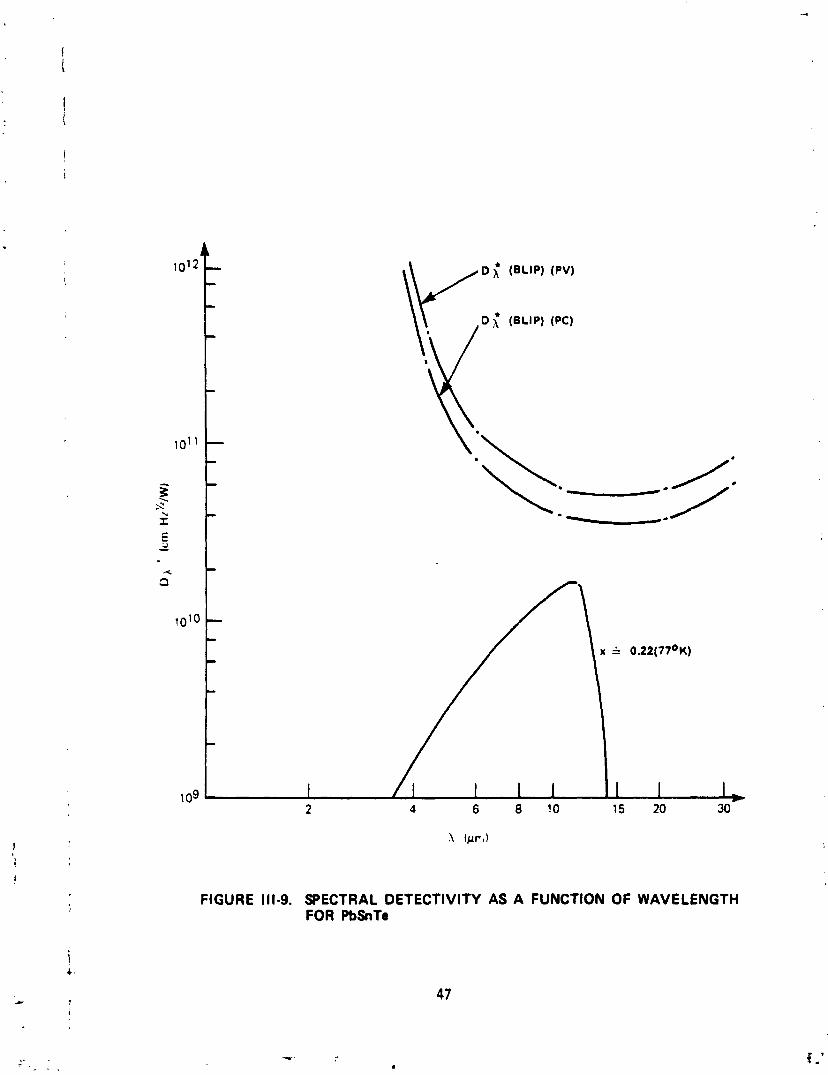
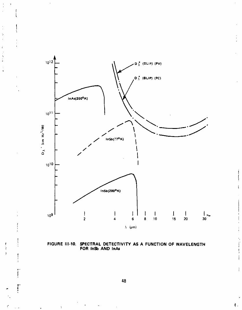
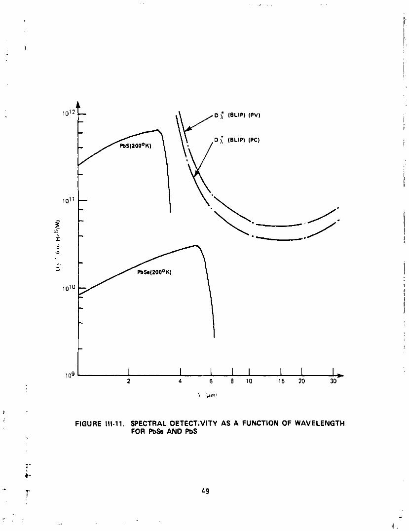
Using the spectra l d e t e c t i v i t y as a measure o f device performance,
Figures 111-7 through 111-11 show the response of devices constructed from
various mater ia ls . The fo l lowing po in ts should be noted:
0 State-of- the-ar t processing provides i s o l a t e d examples o f high-performance mater ia ls .
0 Cooling t o 1 i qu id -n i troqen' temperatures i s requi red t o obta in h igh d e t e c t i v i t y .
0 The data shown are fo r s ing le detectors; t he performance o f detector arrays of uni form response i s no t discussed.
0 Sign i f i can t dev ia t ion f r o m background-1 i m i t ed performance i s seen a t wavelengths below 3 pm.
0 The f i n e s t ruc tu re of the HgCdTe curve for x = 0.18 i s poor ly understood.
e The long-wavelength t a i l o f the Si:Mg curve i s a l so no t we l l understood; i t may be r e l a t e d t o the i n t e r a c t i o n o f c r y s t a l defects and impur i t ies .
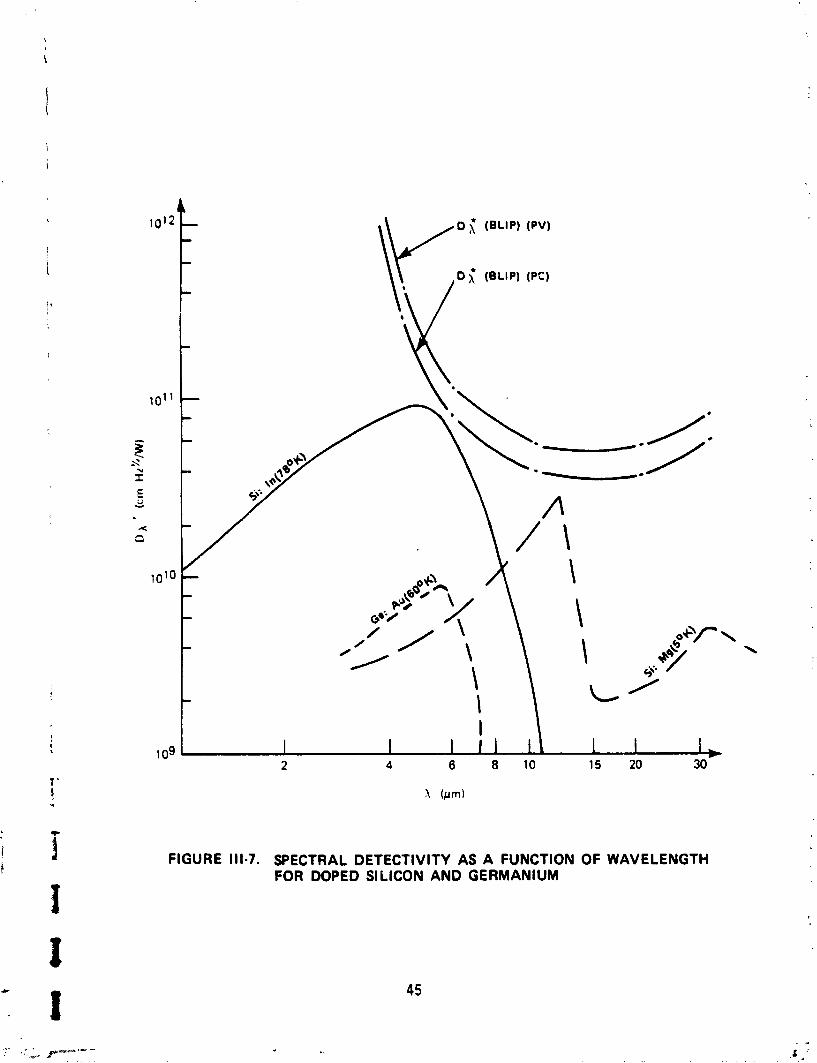
FIGURE 111-7. SPECTRAL DETECTlVlTY AS A FUNCTION OF WAVELENGTH FOR DOPED SILICON AND GERMANIUM
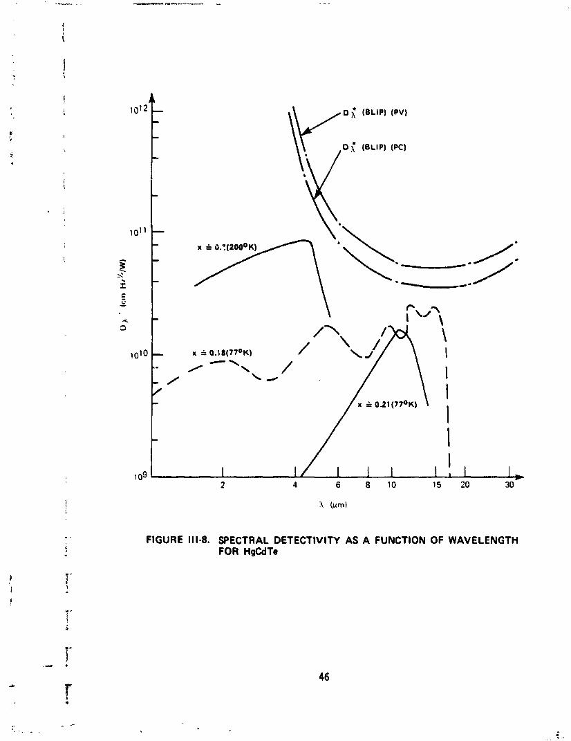
FIGURE 111-8. SPECTRAL DETECTlVlTY AS A FUNCTION OF WAVELENGTH FOR HgCdTe
0 x* (BLIP) (PV)
0 { (BLIP) (PC)
--- 5: ---
FIGURE 111-9. SPECTRAL DETECTIVITY AS A FUNCTION OF WAVELENGTH FOR PbSnTe
- - -
0 (BLIP) (PV)
0 ; (BLIP) (PC)
101' - - - 0' 5: - /'
\ \ --- / 1nSb(77~K)
/ I - I
FIGURE 111-10. SPECTRAL DETECTIVITY AS A FUNCTION OF WAVELENGTH FOR lnSb AND In&
v 0 ;\' (BLIP) (PV)
0 ;; (BLIP) (PC) v *+ --.
5: ---
FIGURE Ill-11. SPECTRAL DETECTiVITY AS A FUNCTION OF WAVELENGTH FOR Pb9 AND PbS
-1. MATERIAL STRUCTURE AND DEVICE PERFORMAffCE
Given the astounding improvement i n the performance of so l i d - s t a t e
devices over the past 30 years and the great pro1 i f e r a t i o n o f t h e i r appl i-
cations, one might expect t h a t the r e l a t i o n between ma te r ia l s t ruc tu re and
device performance would r e s t upon a well-formed physical theory. This i s ,
however, simply n o t the case today. An extensive body o f knowledge does
e x i s t , b u t i t i s n o t systematic and i t f a i l s t o touch upon many re levan t
questions.
I t i s very important t o g i ve some coherence t o our cur ren t knowledge
of .the r e l a t i on between s t r u c t u r e and performance because fu r the r improve-
ments i n s o l i d - s t a t e technology requ i re much more prec ise con t ro l o f mate-
r i a l behavior than i s now possible. High-speed, u l t ra-sensi t i v e detectors
requ i re mater ia ls w i t h impur i t y concentrat ions a t l e a s t 100 times lower than
those c u r r e n t l y a t ta inab le . They a l so requ i re great reduct ion i n the con-
cen t ra t i on of c r y s t a l - s t ruc tu re defects.
I n the absence of a comprehensive physical theory, the best a l t s r n a t i v e
approach i s t o attempt a c o r r e l a t i o n of a semiconductor's e l e c t r o n i c and
s t r u c t u r a l cha rac te r i s t i cc . The important e l e c t r o n i c parameters are pro-
p e r t i e s of the populat ion of charge c a r r i e r s : concentrat ion, m o b i l i t y , and 1 i fe t ime. The mater ia l parameters of i n t e r e s t are the c r y s t a l -defect dens i ty , the impuri t y and dopant concentrat ions, and the composit ional
homogeneity. Many so r t s of c r y s t a l defects may be i d e n t i f i e d , and the
p r i n c i p a l types are discusbed elsewhere i n t h i s repor t ; t h e i r comnon t r a i t
i s a d i s r u p t i o n o f the c r y s t a l ' s pe r iod i c i n t e r n a l geometry. Impur i ty and
dopant concentrat ions simply r e f e r t o the nunber of extraneous atoms found
per u n i t volume o f the c r y s t a l . These extraneous atoms are general ly
termed impur i t ies ; i f they are purposely i n jec ted i n t o the s t ruc ture , i n
order t o prov ide a smal ler energy gap f o r r a d i a t i o n absorpt ion, they are
c a l l e d dopants. The f i n a l mater ia l parameter, composit ional honlogenei t y , denotes the degree t o which the atoms o f a small p a r t o f a compound semi-
conductor conform t o the d e f i n i t e s to ich iomet r ic prupor t ions of the e n t i r e
sample.
We next consider how each of the c a r r i e r propert ies i s l i k e l y t o be
affected by each o f the s t ruc tu ra l paraneters. Carr ier concentration should
show spat ia l nonuniformi t y as one moves from regions of 1 ow c rys ta l -defect
density t o regiors of high crystal-defect densi ty. S i m i t a r nonuniformi t y
may be expected as a r e s u l t of compositional inhomogenities. However, i t
i s not y e t possible t o give a more precise descr ipt ion o f the s ize o f these
effects, the spat ia l scale on which they occur, o r t h e i r consequences for
the photon detect ion process. The effects of impur i ty o r dopant leve ls are
be t te r understood: if the impur i ty donates an electron a t an energy l eve l
w i th in the i n t r i n s i c bandgap, the thermal exc i ta t ion of f ree electrons i n t o
the conduction band w i l l be f ~ c i li tated. If the impur i ty leve l can accept
an e l e c t r ~ n , the thermal exc i ta t ion of electrons f rom the valence band t o
the impurity leve l w i l l be f a c i l i t a t e d and more holes w i l l be generated i n
the valt l lce band.
Carr ier mob i l i t y generally decreases w i t h increasing concentration o f
defects o r impurit ies. I n e f fec t , both of these departures from idea l
c rys ta l st ructure impede the movement of charge car r ie rs by creat ing poten-
t i a l bar r iers which decrease the modes o f f ree propagation avai lable t o the
car r iers . Compositional inhomogenei t i e s create s im i la r barr iers, but 1 i t t l e
data on such effects are cur rent ly avai lable.
Carr ier 1 i fe t ime shows a var iable dependence upon c rys ta l -defect con-
centrat ion. In germanium, the 1 i fe t ime decreases w i t h increasing defect
concentrativn a t high leve ls o f imperfection, but increases w i t h increasing
defect concentration a t low levels o f imperfection. This arises from an
int imate re l a t i on between c rys ta l defects and impur i t ies; impur i t ies appear
t o co l l ec t a t c rys ta l f laws under ce r ta in conditions, thus g iv ing large
port ions o f the bulk crys ta l a lower impur i ty concentration. This e f f e c t
i s pooriy understood. If crys ta l -s t ruc ture defects, compositional inhomo-
genei t i e s and impur i t ies prolong the c a r r i e r 1 i fe t ime by i so l a t i ng chrr-iers
from opposi t e l v charged car r iers , then these imperfections a r c knwn as
"traps"; i f they shorten the l i f e t i m e by f a c i l i t a t i n g the reunion of
oppositely charged carr iers, they are known as "recombination centers."
This discussion shows t ha t we have some idea o f the trends i n the
re l a t i on between material s t ruc ture and e lec t ron ic propert ies, but we are
as y e t i n no pos i t i on t o determine e lec t ron ic parameters by precise cont ro l
of the complex s t ruc tu ra l chemistry of semi conductors.
K. CURRENT DRIV ING FORCES IN DETECTOR DESIGN
A1 though many factors cont r ibute t o deci sions regarding detector
design, we may iden t i f y several dominant goals which w i l l influence design
during the 1980s:
An increase i n number o f array elements a A decrease i n s ize o f array elements
U t i l i za t i on of detector i n staring, ra ther than scanning, mode a In tegrat ion of detector array w i t h charge-coupled devices (CCDs) .
Increasing the number of detector elements allows detect ion of weaker s ig-
nals, whi le decreasing element s ize impraves the spat ia l reso lu t ion o f the
detector. Staring a t a scene allows signal i n tegra t ion and thus ra ises the
signal -to-noise ra t i o . Coup1 i ng the detector array t o a CCD i n the focal
plaae allows information i n each array element t o be read qu ick ly and also
makes possible fast and e f f i c ien t image processing i n the focal plane.
These design goals require an improved understanding of the physical
propert ies of detector materials. Increasing the number o f interconnected
array elements w i l l make un i formi ty of elements desirable. Casting ever smaller elements i s 1 i kely t o incredse the importance of i n t e r f a c i a l e f fec ts
and demand precise control of material behavior. Furthermore, since the
detector and signal -processing port ions of an integrated array may often be
made from d i f fe ren t materials, the mechanical and e lec t ron ic propert ies o f
these mater ia ls w i 11 be o f great in te res t , p a r t i c u l a r l y i n the v i c i n i t y o f
a junction.
I V . METHODS AND PROBLEMS OF CRYSTAL GROWTH
Any I R detector i s l i m i t e d p r i m a r i l y by the care and con t ro l t h a t was
exercised i n the growth of the basic mater ia l . Detector elements are so
small t h a t thermal and mass t ranspor t f luc tuat ions a t even a microscopic
l eve l can ser ious ly degrade the device performance. This chapter offers
a b r i e f 1, *I< a t the processes involved i n the comnon techniques of c r y s t a l
growth.
A. CRYSTAL GROWTH
Crysta l growth i s one manifestat ion of the process of s o l i d i f i c a t i o n .
It represents a phase change on the p a r t of a substance f r o m a s ta te of
lower order t o one of higher order. ,This process occurs as a r e s u l t of
temperature reduct ion (ex t rac t i on o f k i n e t i c energy) and/or pressure
increase. E i the r process a l lows the i n t e r n a l shor t range a t t r a c t i v e forces
between p a r t i c l e s t o become stronger r e l a t i v e t o the k i n e t i c b a r r i e r . The
ind i v idua l p a r t i c l e s , which had r e l a t i v e l y free movement i n the gaseous
s ta te (conf ined only by the conta iner) and l i q u i d s ta te (confined by the
f l e x i b l e boundaries of the l i q u i d ) , are f o r the most p a r t r e s t r i c t e d t o
submicroscopic volumes i n a so l id . I f the arrangement of the p a r t i c l e s i n
the sol i d i s random and i so t rop ic , the s o l i d i s amorphous; if the arrange-
ment has p e r i o d i c i t y along w e l l def ined coordinate axes, the s o l i d i s
cr:rstal l ine. For a p e r f e c t c rys ta l , the p e r i o d i c i t y holds throughout the
volume of the substance w i t h no d i scon t inu i t i es . The t o t a l p o t e n t i a l energy
o f such a s t ruc tu re i s a minimum a t a given temperature. However, t h i s
s ing le c r y s t a l form i s usua l ly not found i n very l a rge st ructures. For
substances t h a t do have a c r y s t a l l i n e phase, t h e i r composition i s normally
p o l y c r y s t a l l ine, made up o f many small i n d i v i d u a l c r y s t a l s or ien ted a t
random. This i s t rue because the f i na l conf igurat ion i s the r e s u l t o f a
time evolut ionary process conducted ovsr a large spat ia l volune. A t the ins tan t o f so l i d i f i ca t i on , the loca l condit ions vary considerably from po in t
t o point . This va r ia t ion leads t o a var ie ty o f c rys ta l defects.
8. CRYSTAL DEFECTS
A f u l l descr ipt ion of c rys ta l st ructure and defects i s f a r beyond the
scope of t h i s report. Instead, a few s impl i f ica t ions can provide a meaning-
f u l basis of understanding. Take, f o r example, a two-dimensional analog o f
c rys ta l structure. I n t h i s model the c rys ta l i s viewed as an array o f
points representing atoms, each rad ia t ing four appendages. Each appendage
o f a point , when matched w i t h an iden t i ca l appendage from another point,
forms a bond locking the two po in ts together. A regular o r symnetric struc-
tu re i s b u i l t up by j o i n i ng many o f these points together w i t h four bonds
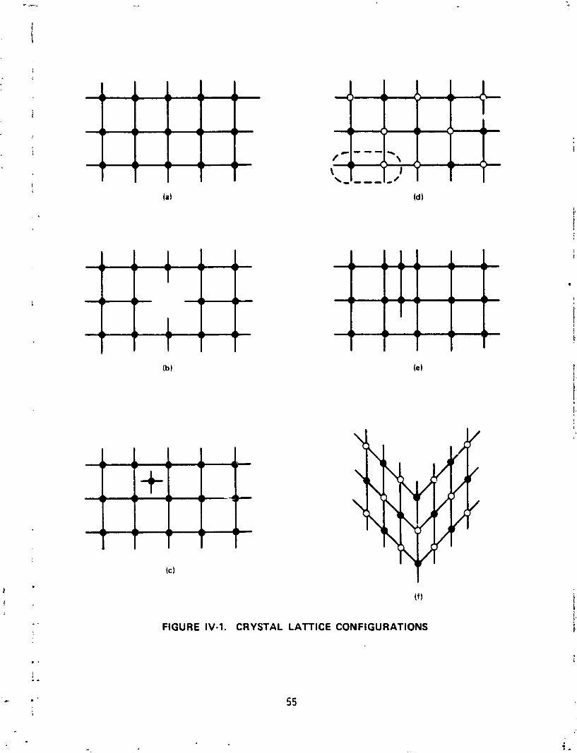
f o r each point. Such a two-dimensional st ructure i s p ic tured i n Figure IV-la.
Inside a structure l i k e t h i s , an imaginary observer a t any i n t e r i o r po in t
would observe surroundings iden t i ca l t o those o f an observer located a t
other points tha t are displaced from the f i r s t po in t by a distance equal t o
an integer mu1 t i p l i e d by a constant. The value of t h i s constant depends on
the d i rec t ion o f displacement. I t i s t h i s nonisotropic pe r i od i c i t y t ha t
defines a c rys ta l and gives r i s e to i t s important propert ies.
A d is rupt ion o f the pe r i od i c i t y w i 11 s ign i f i can t l y a1 t e r the propert ies
o f the material. One such d isrupt ion i s found a t the boundaries o f the
crys ta l . As seen i n Figure IV-la, the boundary i s characterized by dangling
bonds. Since each bond represents an electromagnetic force, the e l ec t r i ca l
propert ies near the edge o f each crys ta l are d i f fe ren t f r o m those i n the
i n te r i o r . An addi t ional d is rupt ion arises f r o m the f a c t tha t the bonds are
not r i g i d . There i s a ce r ta in amount o f e l a s t i c i t y , which permits vibra-
t i ona l movement o f the atoms re l a t i ve t o one another wi thout becoming com-
p l e te l y dissociated. These v ibrat ions a r i se f r o m thermal, mechanical, o r
electromagnetic st imulat ion by outside forces.
(f 1
FIGURE IV-1. CRYSTAL LATTICE CONFIGURATIONS
The above describes fundamental 1 i m i t a t i o n s t o the p e r i o d i c i t y o f any
st ructure. Other d is rupt ions are l ess fundamental and are known as defects.
Defects can range f r o m zero t o th ree dimensions i n character. The zero-
dimensional p o i n t defects are o f several types. If a l a t t i c e s i t e i s missing
an atom, as shown i n Figure IV-lb, i t i s known as a vacancy. If, instead,
an atom i s found i n the s p a t i a l volume between l a t t i c e s i t es , as shown i n
Figure IV- lc , i t forms an i n t e r s t i t i a l . These i s o l a t e d p o i n t defects are
character ized by a d e f i n i t e energy o f formation. This energy a r i ses from
l o c a l thermal f l u c t u a t i o n s a t the t ime of c r y s t a l l i z a t i o n w i t h a p r o b a b i l i t y
of formation given by
p r o b a b i l i t y of formation a exp [-Ef/kT]
where Ef i s the formation energy and depends on the type o f defect. The
probabi 1 i t y of formation increases w i t h the temperature a t which so l i d i f i -
ca t i on occurs. This ind ica tes t h a t c r y s t a l 1 i zat ion processes t h a t can
be accompl ished a t lower temperatures are more desi rable. I n add i t ion ,
once 2 po in t de fec t i s formed i t i s r e l a t i v e l y mobile, depending on the
ambient temperature of the l a t t i c e . The p r o b a b i l i t y o f moving t o a d i f f e r -
en t s i t e has the same dependence as the p r o b a b i l i t y of formation w i t h Em,
the energy of displacement, s u b s t i t u t i n g f o r Ef. Ef i s t y p i c a l l y a few
e lec t ron v o l t s i n magnitude wh i le Em may be on ly a few tenths. I n t h i s
motion through the l a t t i c e , p o i n t defects may meet and c o l l e c t o r "condense"
i n t o c lus te rs o f many p o i n t defects, which can a c t as the source of d i f f e r -
ent and more widespread defects.
I n the previous discussion, the two-dimensional model consisted of
only a c r y s t a l conta in ing a s ing le atomic species. The l i s t of p o i n t
defects f o r c r y s t a l s formed from more than one atomic species i s augnented
by those defects formed when an unwanted impur i ty subst i tu tes f o r a regu lar
l a t t i c e o r acts as an i n t e r s t i t i a l , o r when the order ing o f species i s
interchanged as shown i n Figure IV- ld. The f a c t t h a t p o i n t defects are so
e a s i l y formed mans t h a t they can probably never be completely el iminated.
Their presence must provide the fundamental 1 i m i t a t i o n s on the e lec t ron ic
behavior of c rys ta l s , such as charge c a r r i e r m o b i l i t y and l i f e t i m e . Except
when present i n l a rge c l u s t e r s such as s i l i c o n sw i r l s , t h e i r presence i s
no t r e a d i l y ava i l ab le t o d i r e c t methods of detect ion, making i t d i f f i c u l t
t o make d i r e c t c o r r e l a t i o n between e lec t ron ic behavior and p o i n t defect
concentration.
The descr ip t ion of p o i n t defects was fac i 1 i ta ted w i t h the a i d o f a two-dimensional model. Higher dimensional defects requ i re the extension
of t h i s mudel t o th ree dimensions. It i s necessary t o imagine t h a t the
two-dimensional l a t t i c e i s repeated i n d e f i n i t e l y i n the d i r e c t i o n perpen-
d i c u l a r t o the paper. If a shear force i s app l ied t o a block o f t h i s
mater ia l i t may a t some l e v e l exceed the e l a s t i c i t y ava i l ab le i n the
inter-atomic bonds. Slippage may occur along one plane o f atoms, and a
new e q u i l i b r i u n p o s i t i o n may be achieved i n which a h a l f plane o f atoms,
terminated w i t h dangl ing bonds a t the sl ippage plane, i s found squeezed
between two other planes. These adjacent planes have a l l t h e i r bonds
pai red but are under some tension. An end view of t h i s conf igurat ion,
known as an edge d is locat ion , i s represented by Figure IV- le. The shear
forces t h a t produce these edge d is locat ions can a r f se from stresses produced
by high thermal gradients i n a coo l i ng so l i d , by unmatched thermal expansion
coef f i c ien ts of the sol i d and any container, o r by unmatched l a t t i c e para-
meters o f an e p i t a x i a l l y grown laye r and the substrate. The chain o f
dangl ing bonds forming the boundary of an edge d i s l o c a t i o n represents an
e lec t ron ic anomaly i n the l a t t i c e . This can a c t as a t r a p fo r charge
c a r r i e r s o r i t can p i n impur i ty atoms, producing various undesirable conse-
quences f o r c a r r i e r l i f e t i m e and mobil i ty . Even i n the best o f c r y s t a l s 3 -2 the densi ty o f edge d is locat ions o r s i m i l a r defects i s t y p i c a l l y 10 cm .
Two types o f defects t h a t do not necessar i ly r e s u l t i n dangl ing bonds
are the screw d i s loca t ion and the l a t t i c e twin. Screw d is locat ions are
character ized by a s p i r a l ramp type of t r a n s i t i o n from one c r y s t a l plane
t o the next ra the r than by one laye r placed upon the other. The o r i g i n o f
these d i s l o c a t i ons i s no t c l e a r l y understood, a1 though some mechanisms have
been suggested a r i s i n g f r c m an ar ray of edge d i s loca t ions o r p o i n t defects.
Twin boundaries a r i s e f r o m s l i g h t l a t t i c e displacements due t o st ress.
The l a t t i c e s t ruc tu re on one s ide o f the tw in plane i s the m i r r o r image
o f the other. An example i s shown i n Figure IV-lb. Twinning i s more l i k e l y
t o occur a t low temperatures than s l i p s producing edge d is locat ions . The
major e f f e c t s o f screw d i s loca t ions and twins are a l te red d i r e c t i o n a l pro-
p e r t i e s and s t r a i n energies.
The next l eve ls o f defects, cons is t i ng of g ra in boundaries (a surface
o f d is locat ions forming the boundary between c r y s t a l s o f d i f f e r e n t o r ien ta-
t i o n ) and occlusions o f impur i t ies , are d isastrous f o r any detec tor mater ia l .
These r e s u l t from complete l ack of con t ro l over the c r y s t a l growth in ter face.
Various other types of defects can be i d e n t i f i e d and 'labeled, bu t they d i f f e r
from those already mentioned i n shape ra the r than substance. They a re gen-
erated frm the same general condi t ions as the others.
C. THE CRYSTAL GROWTH INTERFACE
The in ter face i s the instantaneous boundary between the advancing
s o l i d and the substance t h a t provides the raw mater ia l t o f u e l the c ry -
s t a l ' s grawth. This substance may be a gas, a l i q u i d , o r even another
so l i d . If the n u t r i e n t o r noncrys ta l l ine phase i s a l i q u i d o r gas, i t s
p a r t i c l e s are r e l a t i v e l y f r e e t o move about. That i s , t h e i r k i n e t i c
energy exceeds the a t t r a c t i v e p o t e n t i a l energy e x i s t i n g a t the c r y s t a l
boundary. If some mechanism e x i s t s t o reduce a p a r t i c l e ' s energy, i t may
become trapped i n the p o t e n t i a l we l l o f the l a t t i c e and thus become a p a r t
o f it. Conservation o f energy requires t h a t the k i n e t i c energy l o s t by the
newly bound p a r t i c l e appear elsewhere. I f the energy i s l o s t due t o an
i n e l a s t i c c o l l i s i o n w i t h the l a t t i c e , i t appears as a phonon ( l a t t i c e
v i b r a t i o n ) and cont r ibu tes t o heat ing the l a t t i c e . I f the energy i s l o s t
from an i n e l a s t i c c o l l i s i o n w i t h another p a r t i c l e i n the nonc rys ta l l i ne
phase, i t contr ibutes t o an increase i n temperature o f t h a t mater ia l . A
reverse process can a lso occur. If an energet ic p a r t i c l e i n the n u t r i e n t
materia' s t r i k e s the l a t t i c e w i t h s u f f i c i e n t force, i t may break the bonds
o f a l a t t i c e atom and thus increase the amount o f the noncrys ta l l ine phase.
I n t ru th , both processes occur simultaneously. I f the former process i s
more frequent, we have net c r y s t a l growth; i f the l a t t e r predominates, we
have a net c r y s t a l shrinkage due t o melt ing, vaporizat ion, o r d isso lu t ion .
The growth process requires tha t thermal energy be transferred out o f the
system. I n cont ro l led growth processes the heat i s transferred out of the cooled s o l i d phase. The overa l l growth ra te of the c rys ta l l i n e phase depends
on i t s heat t ransport propert ies (governed by thermal conduct iv i ty and the
temperature gradient present) and on the mass and thermal t ransport proper-
t i e s o f the noncrysta l l ine phase.
The above discussion described the so l i d i f i ca t i on process simply but
adequately. However, i t does not introduce any mechanism tha t controls cry-
s t a l perfection. This can best be described by looking a t an equ i l ib r ium
s i tua t ion consist ing of a perfect c rys ta l i n contact w i th a l i q u i d (o r gas)
of the same composition held a t the mel t ing (o r subl imination) temperature
of the material. A t equ i l ib r ium there w i 11 be no net gain or loss of mate-
r i a l by the s o l i d phase. On a loca l microscopic leve l , however, there w i l l
be a continuous process i n which pa r t i c l es become attached t o and released
from the interface. These two processes balance each other. The pa r t i c l es
of the noncrystal phase may at tach themselves t o the sol i d in ter face i n
various configurations, some of which do not preserve the per fec t c rys ta l
structure. However, since the per fec t c rys ta l represents an energy minimum,
the a t t r a c t i v e bonds are strongest i n tha t configuration. Therefore i n the
equ i l ib r ium state, w i t h i t s continual process o f attachment and detachment
driven by the s t a t i s t i c a l v a r i a t i o ~ o f k i ne t i c energy, the bonds most read i l y
broken are those tha t could preserve defects. Even so, a t any given t i m e
there are 1 i k e l y t o be a number o f po in t defects. It i s however, tke pro-
cess o f r e v e r s i b i l i t y i n the equ i l ib r ium s i t ba t i on tha t keeps these defects
t o a minimum.
As the process i s moved away from equi l ib r ium by ext rac t ing heat finom
the system, both processes s t i l l octur. However, the attachment process
happens a t a greater r a te so tha t the s o l i d so l i d i f i ca t i on f ront advances
and freezes i n any defects. Although the bonds corresponding t o a per fec t
c rys ta l may be strongest, they may not be the ones most l i k e l y t o be formed
a t a given instant . I t i s only i n the equ i l ib r ium revers ib le process t ha t
they are overwhelmingly dominant. I n a dynamic growth s i tuat ion, the per-
centage of defects i s therefore more l i k e l y t o increase as the growth r a t e
increases. Another fac to r tha t leads t o more defects i s higher temperature.
The higher temperature means t h a t there i s a greater f r a c t i o n of p a r t i c l e s
w i t h energy su f f i c i en t t o break the stronger bonds of t he newly created
atoms forming the per fect s t ruc ture .
The above s i t u a t i o n i s comparatively simple i n t h a t i t deals only w i t h
a pure substance. It does ind i ca te t h a t more defects are l i k e l y t o occur
a t higher temperatures and higher growth rates. For r e a l i s t i c systems
having several components and w i t h l ess con t ro l over temperature and com-
pos i t ion , the environment a t the in ter face i s much more complex. For the
pure substance, the per fect c r y s t a l represented a minimum energy state. As such, there was a d e f i n i t e ove ra l l tendency t o produce such a state. I n
the case o f m i x ~ d substances, the desired composition i s 1 f ke l y t o represent
only a l o c a l energy minimum, which can be achieved w i t h i n a very narrow
range o f cont ro l var iables such as temperature, pressure, and composition.
Even if these va iables are we1 1 c o n t r o l l e d on a macroscopic l e v e l , normal
s t a t i s t i c a l f l uc tua t ions w i l l se t l i m i t a t i o n s on the l e v e l of microhomogeneity
t h a t can be achieved.
A1 though there are numerous problems pecu l i a r t o each ind i v idua l system,
an examination of a few example cases can i l l u s t r a t e major common d i f f i c u l t i e s .
Case 1: Growth o f a Pure Single Element Crysta l
I n t h i s hypothet ica l pure substance we need not worry about segrega-
t i o n of components. The on ly imperfect ions t h a t can a r i s e are s t r u c t u r a l
defects. The most simple defects are p o i n t defects and may be o f two
types: vacancies o r i n t e r s t i t i a l s . They are i l l u s t r a t e d i n Figures IV - lb
and IV- lc . Each o f these defects i s character ized by an energy o f formation
Ef and an energy o f m o b i l i t y Em. As discussed previously, the p r o b a b i l i t y
o f formation and m o b i l i t y are r e l a t e d t o the temperature by
Pf a exp [-Ef/kT]
Pm a exp [-Em/kT] . The m o b i l i t y o f the po in t defects can lead t o several consequences. If both
vacancies and i n t e r s t i t i a l s are present i n the l a t t i c e , the random meeting
60
of two opposites w i l l ann ih i la te each other. If two vacancies o r two i n te r -
s t i t i a l ~ jo in , the defect energy w i l l be reduced since there w i l l be fewer
unpaired bonds. Thus, there i s a tendency t o form large defect st ructures
from coalescing o r condensed po in t defects. Depending on the density o f
such defects and on the nature o f the device, the condensation may o r may
not be desirable. The rnobil i ty of the defects i s enhanced by annealing the
c rys ta l a t some elevated temperature. This process can r e s u l t i n defect
ann ih i la t ion, condensation, o r i t can cause defects t o move t o the surface
and disappear. I f the condensation i s not desirable, the c r ys ta l can be
rap id ly cooled, thus freezing the ind iv idua l po in t defects i n place.
Case 2: Growth o f a Sinqle Element Crystal With Impurity
The impur i ty may be in tent fona l o r unintentional. Unintentional addi-
t i ves ar ise due t o l im i t a t i ons of the pur f f i ca t ion process, o r they enter
l a t e r as contaminants di f fusing out of a container i n high temperature cry-
s t a l l i za t i on steps. In tent iona l addi t ives are dopants, which must be incor-
porated uniformly i n bulk c rys ta l growth o r perhaps gradient ly i n ep i t ax i a l
growths. I n e i t he r case, the dopant atoms may subst i tu te for the predominant
specie i n the host l a i t i c e o r enter i n t o i n t e r s t i t i a l locations. The c r ys ta l
grower now has the dual goal of achieving s t ruc tu ra l perfect ion along wi,th
compositional mi formi ty.
For dopants there i s f requent ly a l i m i t a t i o n t o the maximum amount of
solute material which can be incorporated i n t o the hcst c rys ta l . The solu-
b i l i t y o f the dopant i s usual ly gredter i n the l i q u i d mixture than i n the
sol id. A t sorite concentration the in te rac t ion forces between the dopant atoms
pass a threshold o f nucleation a t which po in t they form prec ip i ta ted aggre-
gates rather than remain as iso la ted indiv iduals. These large aggregates
can apply s i gn i f i can t stress t o the cooled l a t t i c e , introducing various
s t ruc tu ra l defects.
Even a t concentrations below the s o l u b i l i t y l i m i t , the equ i l ib r ium con-
centrat ion o f solute d i f f e r s between the c rys ta l and noncrystal phase. For
example, a t equi l ibr ium the s o l i d and l i q u i d concentrations of the solute a t the in ter face are re la ted by ko = C,/CI. For ko < 1, some of the solute i s
cont inua l ly re jected from being incorporated i n the so l i d phase. This, l e f t
alone, produces a concentration gradient on the l i q u i d side of the so l id -
l i q u i d fnterface. A t t h i s po in t one of two d i s t i n c t processes can occur.
If a mechanism ex is ts t ha t can mix the l i q u i d " i n f i n i t e l y " fast, the re jec ted
solute can be dispersed uniformly throughout the remainder o f the l i q u i d .
Under t h i s mechanism the concentration o f the so lu te i n the remaining l i q u i d
increased s tead i ly . This increase i s r e f l ec ted by a pa ra l l e l increase, but
s t i l l a t a lower leve l , i n the concentration i n the sol id. I n the t o t a l
absence of any such fas t mixing mechanism the concentration of the solute
i n the inter face boundary w i l l increase u n t i l i t reaches a po in t a t which
the d i f fus i ve loss of so lu te i n t o the bulk l i q u i d i s equal ly balanced by the
gain as it i s re jec ted from the so l id . A t t h i s stage the concentration o f
the solute i n the s o l i d w i l l maintain a steady value u n t i l near ly a l l the
l i q u i d has so l i d i f i ed , a t which po in t there w i l l be a sharp increase. Curves representing the two processes are shown i n Figure I V - 2 . Since i t i s the
equ i l ib r ium (o r segregation) coe f f i c i en t KO and the concentration i n the
l i q u i d phase t ha t determine the concentration i n the so l id , any var ia t ions
o f solute concentration along the l i q u i d side of the in te r face caused by
currents o f any k ind w i l l be reproduced t o some scale i n the sol id.
The above d i ~ c u s s i o n was concerned w i t h the in ten t iona l incorporat ion
o f dopant. The other side o f the coin deals w i t h undesirable contaminants.
For any growth processes i n which hot mater ia l (espec ia l ly molten) i s i n
contact w i th a container, there i s always, t o some extent, d i f f u s i o n o f
undesirable species from the container t o the growing crys ta l . These con-
taminants t y p i c a l l y w i 11 be d is t r i bu ted nonuniformly. For appl i c a t i ons i n
which impur i ty concentrations o f the order o f par ts per b i l l i o n o r less are
required, the cont r ibut ions of the unwanted contaminants can be serious.
Case 3: Growth o f Mu1 ticomponent Al loys and Compounds
Heavily doped m t e r i a l s would a lso have problems s im i la r t o those o f
t h i s case, whi le t h i s case would include a l l the problems o f the other two
:a ses.
The complexity involved i n describing the processes leading t o c r ys ta l -
l i z a t i o n o f multicomponent mater ia ls ar ises 'ram ,the mul t i tude of i n t e r -
atomic forces tha t are present. These forces are of d i f fe rent strengths
62
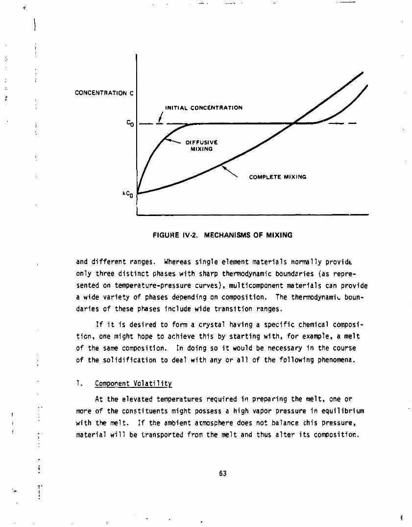
CONCENTRATION C
co
I INITIAL CONCENTRATION
I / MIXING
FIGUHE IV-2. MECHANISMS OF MIXING
and d i f f e r e n t ranges. Whereas s i n g l e element mater ia ls normal ly prov idc
on ly three d i s t i n c t phases w i t h sharp thermodynamic boundzries (as repre-
sented on temperature-pressure curves), mu1 ticomponent mater ia ls can prov ide
a wide v a r i e t y o f phases depending on composition. The thermodynami~ boun-
dar ies o f these phases inc lude wide t r a n s i t i o n ranges.
If i t i s desi red t o form a c r y s t a l having a spec i f i c chemical composi-
t i c n , one might hope t o achieve t h i s by s t a r t i n g w i th , f o r example, a me l t
of the same composition. I n doing so i t would be necessary i n the course
of the s o l i d i f i c a t i o n t o deal w i t h any o r a l l o f the f o l l o w i n g phenomena.
1. Component V o l a t i l i t y
A t the elevated temperatures requ i red i t \ p repar ing the melt , one o r
more o f the cons t i tuents might possess a h igh vapor pressure i n e q u i l i b r i u m
w i t h the melt . If the ambient a t f n ~ s ~ h e r e does not balance chis pressure,
mater ia l w i l l be t ransported from the mel t and thus a l t e r i t s composition.
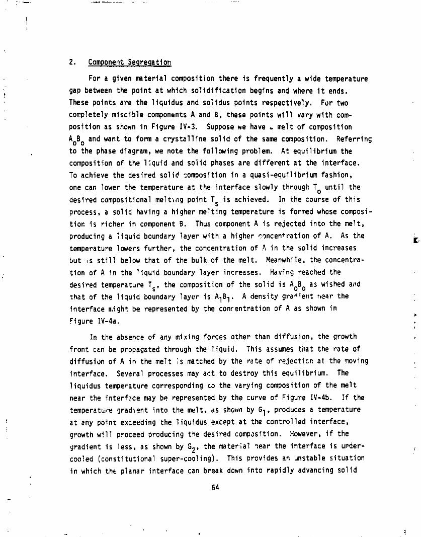
2. Component Seqreqati on
For a given mater ia l composit ion there i s f requent ly a wide temperature
gap between the p o i n t a t which s o l i d i f i c a t i o n begins and where i t ends.
These po in t s a re the l i q u i d u s and so i idus po in t s respect ive ly . For two c o ~ p l e t e l y m isc ib le components A and B, these po in t s w i l l vary w i t h com-
p o s i t i o n as shown i n F igure IV-3. Suppose we have a mel t o f composit ion
AoBo and want t o form a c r y s t a l l i n e s o l i d o f the same composition. Referr ins
t o the phase diagram, we note the fo l low ing problem. A t equ i l i b r i um the composition o f the l f q u i d and s o i i d phases are d i f f e r e n t a t the i n te r face .
To achieve the desi red s o l i d composition i n a quas i -equ i l ib r ium fashion,
one can lower the temperature a t the i n t e r f a c e s lowly through To u n t i l the
desi red composit ional m e l t r ~ i g p o i n t TS i s achieved. In the course of t h i s
process, a sol i d having a h igher me1 t i n g temperature i s formed whose composi-
t i o n i s r i c h e r i n component B. Thus component A i s re jec ted i n t o the me1 t,
producing a t i q u i d boundary l aye r w i t h a h igher r ~ n c e n t r a t i o n o f A. As the
temperature lowers fu r the r , the concentrat ion o f .\ i n the s o l i d increases
b u t I S s t i l l below t h a t o f the bu lk o f the melt . Meanwhile, the concentra-
t i o n o f A i n the ' i q u i d boundary l a y e r increases. Having reached the
desi red temperature Ts, the composit ion o f the s o l i d i s AoBo a i wished and t h a t o f the l i q u i d boundary l a y e r i s AIB,. A dens i ty g r a d e r i t near the
i n t e r f a c e might be represented by the concentrat ion o f A as shown i n
Figure IV-4a.
I n the absence o f any mix ing forces o ther than d i f fus ion, the growth
f ron t cen be propagated through the l i q u i d . This assumes t h a t the r a t e of
d i f fus idn o f A i n the me l t ;s matched by the r a t e o f r e j e c t i c n a t the qoving
in ter fzce. Several processes may a c t t o destroy t h i s equi 1 i b r i um. The
1 iquidus temperature corresponding sa the vary ing composit ion o f the me1 t
near the in te r face may be represented by the curve of F igure IV-4b. If the
temperature gradlent i n t o the melt , ds shown by El, produces a temperature
a t any p o i n t exceeding the 1 iqu idus except a t the c o n t r o l l e d in ter face,
growth w i 11 proceed producing the desi red compasi ti on. However, if the
gradient i s less, as shown by G2, the mater;al Tear the i n t e r f a c e i s uvder-
cooled ( c o n s t i t u t i o n a l super-coo? ing) . This provides an unstable s i t u a t i o n
i n which thc p lanar i n t e r f a c e can break down i n t o r a p i d l y advancing s o l i d
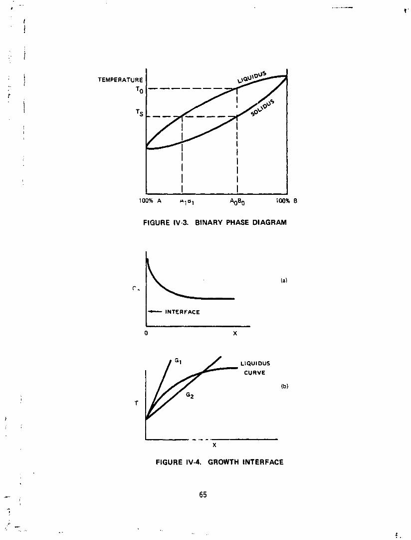
TEMPERATURE
100% A H ~ b l 'kOO 100% 8
FIGURE IV-3. BINARY PHASE DIAGRAM
C- INTERFACE
LlQUl ous CURVE
(b)
T
FIGURE IV-4. GROWTH INTERFACE
pro jec t ions having one composition t h a t surround 1 i q u i d channels having a
d i f f e r e n t composition. The r e s u l t i n g c r y s t a l i s inhomogeneous.
Another growth phenomenon of concern i s the problem o f facet ing. I n
most processes i n v o l v i n g c o n t r o l l e d growth a seed c r y s t a l i s used t o i n i t i a t e
growth along a s p e c i f i c ax is . I f an isothermal plane can be maintained per-
pendicular t o t h i s axis, growth w i l l usua l ly be acnieved i n t h i s plane.
However, most isothermals have some curvature, b r i ng ing them p a r a l l e l t o
other c rys ta l lograph ic planes. These other planes may have s l i g h t l y d i f f e r -
en t growth propert ies, such as d i f f e r e n t s o l i d i f i c a t i o n temperature and
d i f f e r e n t segregation c o e f f i c i e n t s f o r impur i t i es and solutes. If growth
progresses a1 ong these other axes, compositional i n homogenei t y w i 1 1 r e s u l t .
D. INSTABILITY MECHANISMS
The environment i n which c r y s t a l growth takes p l a ~ e i s r a r e l y quiescent.
Not on l y i s i t necessary t o f i r s t es tab l i sh the proper condi t ions t o produce
a su i tab le c r y s t a l , bu t i t i s a l so essent id l t o design a system t h a t does not
become imbalanced by the random perturbat ions t h a t are bound t o occur. These
random perturbat ions (which a t t he very l e a s t can a r i s e from s t a t i s t i c a l
f l uc tua t ions ) i n themselves are the source o f many microinhomogenei t i e s .
More important, however, i s t h e i r e f f e c t on the system as a whole. I f the
system reacts i n a manner t h a t tends t o res tore the i n i t i a l u n ~ e r t u r b e d
state, the system i s s tab le On thz other hand, i f the system reacts i n such
a way as t o re in fo rce the per turbat ion, the system i s unstable. If the con-
d i t 'ons t h a t gave r i s e t o the s t a b i l i t y are maintained, a f low pa t te rn w i l l
develop. Some sources o f i n s t a b i l i t y t h a t may be present i n c r y s t a l growing
operat ions are examined.
1. Gravi ty Driven Convection
The grav i ta t iona ' fo rce on any volume o f f l u i d i s proport ional t o the
amount of mas- i n t h a t volume, i .e. , t he mass density. Most f l u i d s expand
when heated, thus decreasing t h e i r density. Therefore, f o r a pure substance
the g rav i ta t i ona l fo rce i s greater i n the coo ler po r t i on o f the f l u i d . F ig-
ures IV-Sa through 5c show three types o f heat ing conf igurat ions. The arrows
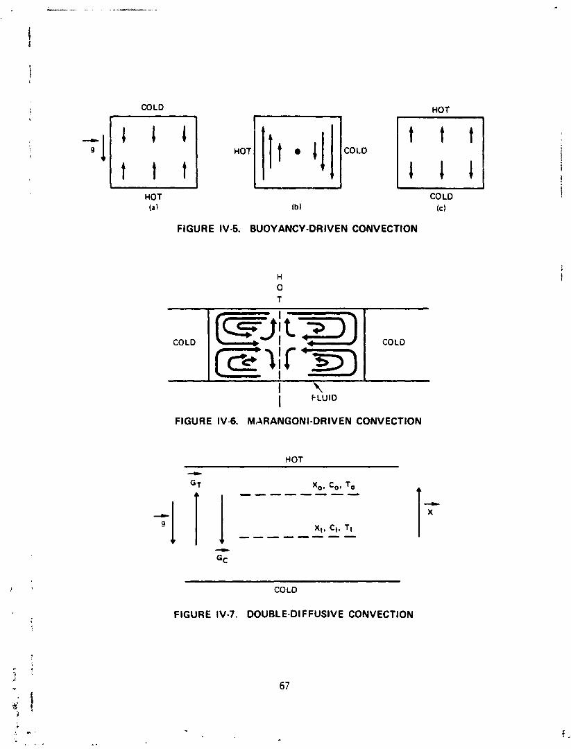
COLD HOT
HOT (a 1
COLO (c 1
FIGURE IV-5. BUOYANCY-DRIVEN CONVECTION
I
I I FLUID
T
FIGURE IV-6. MARANGONI-DRIVEN CONVECTION
HOT
COLD COLD
COLO
(!/t)I
FIGURE IV-7. DOUBLE-DIFFUSIVE CONVECTION
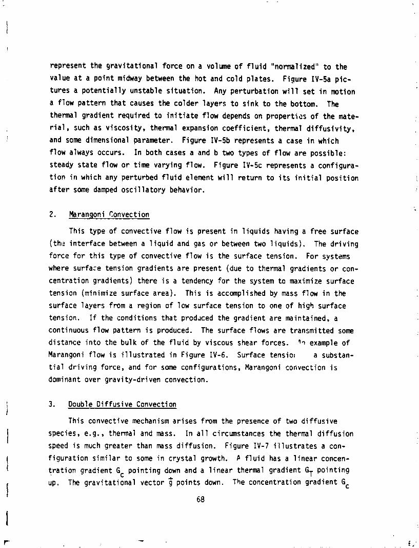
represent the grav i ta t iona l force on a volume of f l u i d "normalized" t o the
value a t a po in t midway between the hot and co ld plates. Figure IV-5a p i c - tures a po ten t i a l l y unstable s i tuat ion. Any perturbation w i l l set i n motion
a flow pat tern tha t causes the colder layers t o s ink t o the bottom. The thermal gradient required t o i n i t i a t e flow depends on propert ies o f the mate-
r i a l , such as v iscosi ty, t h e m 1 expansion coeff icient, thermal d i f f us i v i ty,
and some dimensional parameter. Figure IV-5b represents a case i n which
f low always occurs. I n both cases a and b two types o f flow are possible:
steady state f low o r time varying flow. Figure IV-5c represents a configura-
t i o n i n which any perturbed f l u i d element w i l l re turn t o i t s i n i t i a l pos i t i on
a f t e r some damped osc i l l a t o r y behavior.
2. Marangoni Convection
This type o f convective flow i s present i n 1 iquids having a free surface
( the inter face between a l i q u i d and gas o r between two l i qu i ds ) . The d r i v i ng
force f o r t h i s type of convective flow i s the surface tension. For systems
where surface tension gradients are present (due t o thermal gradients o r con-
centrat ion gradients) there i s a tendency for the system t o maximize surface
tension (minimize surface area). This i s accomplished by mass f low i n the
surface layers from a region o f low surface tension t o one of higb surface
tension. If the condit ions tha t prod~ced the gradient are maintained, a
continuous flow pat tern i s produced. The surface flows are transmitted some
distance i n t o the bulk of the f l u i d by viscous shear forces. 4~ example of
Marangoni flow i s i l l u s t r a t e d i n Figure IV-6. Surface tens io~ a substan-
t i a l d r i v i ng force, and for some configurat ions, Marangoni convection i s
dominant over gravi ty-dr iven convection.
3. Double D i f fus ive Convection
This convective mechanism ar ises from the presence of two di f fusive
species, e.g., thermal and mass. I n a l l circumstances the thermal d i f f us i on
speed i s much greater than mass diffusion. Figure IV-7 i l l u s t r a t e s a con-
f igurat ion s im i la r t o some i n c rys ta l growth. P f l u i d has a l i nea r concen-
t r a t i o n gradient Gc po in t ing down and a l i nea r thermal gradient po in t ing
up. The grav j ta t iona l vector 3 points down. The concentration gradient Gc
i s tha t o f the less dense consti tuent. Assune a mass density a t any po in t
x r e l a t i v e t o t ha t a t po in t xo i s given by
where B~ and 6, are pos i t i ve constants r e l a t i n g density t o temperature and
concentration differences. A t f i r s t glance we might th ink t ha t the con-
f igurat ion i s stable if BTGT + 6,GC > 0. This would ensure t ha t the less
dense mass i s a t the top, w i t h no p o s s i b i l i t y of g rav i t y driven (buoyancy)
convection. This, however, does not take i n t o account the dynamics involved
i n a perturbed s i tuat ion. Assune a small volume o f the f l u i d i s displaced
from pos i t i on xo t o pos i t i on xl. I n the course of the displacement, over
a f i n i t e time in te rva l , d i f f us i ve forces w i l l t r y t o equ i l i b ra te the d is -
placed volurne w i t h i t s surroundings. The thermal d i f f us i v i t y being so much
fas ter , i t can be assumed tha t upon reaching xl the temperature of the d is - placed f l u i d has reached T1 whi le i t s concentration i s s t i l l co. Thus i t s
density a t xl i s now
whi le tha t o f the surroundings i s
The di f ference i s
> 0 since xl e x a n d G c c O . 0
ThereforL the displaced f l u i d i s denser than i t s surroundings and i t w i l l
continue t o f a l l . A s im i la r analysis f o r a f l u i d element disolaced upward%
would show t h a t i t would cont inue t o r i s e . Both cond i t ions represent i ns ta -
b i l i t y . Although the l i n e a r gradients postu lated i n the example a re n o t
necessar i ly r e a l i s t i c , the example shows t h a t the p o t e n t i a l e x i s t s fo r t h i s
type o f convect ive f low. Analysis fo r more complex gradients provides the
c r i t e r i a necessary f o r t he i ns tab i 1 i t y t o e x i s t .
4. Add i t iona l Flow I n s t a b i l i t i e s
Other f l ow i n s t a b i l i t i e s can be introduced by add i t i ona l d r i v i n g mech-
anisms. I f r o t a t i o n i s used i n p u l l i n g a c r y s t a l from a melt, convectional
f low dr iven by c e n t r i f u g a l fo rce i s introduced. If RF heat ing i s used on a
m e t a l l i c melt, there are magnetic body forces exerted on the induced currents.
Crysta ls are r o u t i n e l y prepared from a v a r i e t y o f s t a r t i n g mater ia ls i n
any of several phases. The method used f o r any s p e c i f i c composition i s
determined f i r s t by what i s chemical l y and thermodynamically possible, then
by qua1 i t y and quan t i t y o f the product. The source mater ia l may be a 1 i q u i d
c r vapor phase. Several growth mechanisms are described i n genera1 terms.
1. Czochral s k i Growth
This method involves "pu l l i ng " a s o l i d i f i e d c r y s t a l s lowly from a mel t
(Figure IV-8). A seed c r y s t a l of proper o r i e n t a t i o n i s i n i t i a l l y dipped
i n t o the molten batch and withdrawn slowly. Cool ing through the seed and
crysta' hc lder permits a continuous process of s o l i d i f i c a t i o n . The d ia-
meter o f the c r y s t a l can be con t ro l l ed by the p u l l ra te . Since the growing
c r y s t a l i s not confined, s t r u c t u r a l defects caused by d i f f e r e n t expansion
coe f f i c i en ts f o r c r y s t ~ . l and container are e l iminated. The c r y s t a l i s
ro ta ted t o enhance thermal un i fo rm i t y across the growth in ter face and
t o a i d i n mix ing any dopants added t o the melt . This method of growth
i s f i n e f o r c rys ta l s which do not have v o l a t i l e components. However, f o r
mater ia ls having const i tuents w i t h high vapor pressures, i t i s extremely
d i f f i c u l t and p r o h i b i t i v e l y expensive t o fab r i ca te a sealed Czochralski
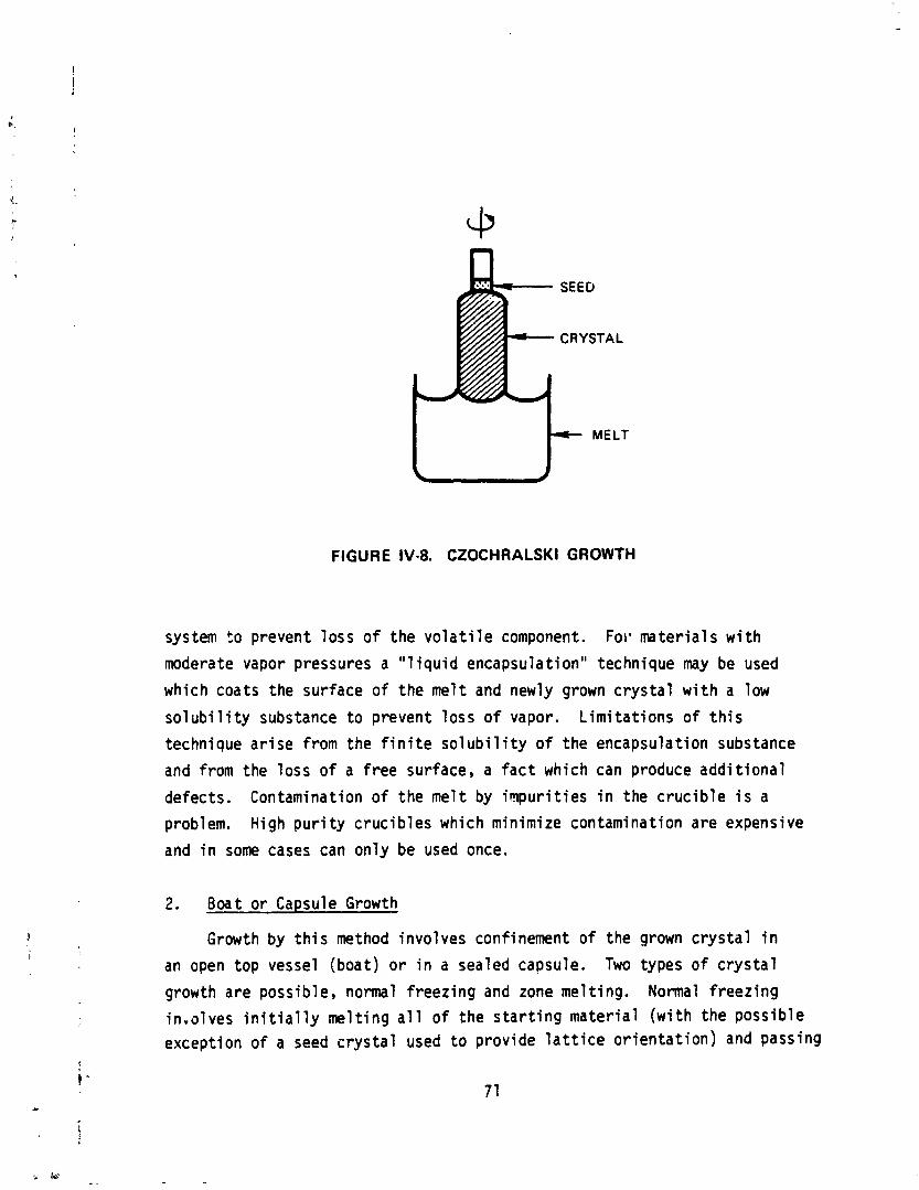
FIGURE IV-8. CZOCHRALSKI GROW1 H
system t o prevent l oss of the v o l a t i l e component. For* mater ia ls w i t h
moderate vapor pressures a "1 i q u i d encapsulat ion" technique may be used
which coats the surface of t he me1 t and newly grown c r y s t a l w i t h a low
s o l u b i l i t y substance t o prevent loss o f vapor. L im i ta t i ons of t h i s
technique a r i s e from the f i n i t e s o l u b i l i t y of the encapsulation substance
and from the l oss o f a free surface, a fac t which can produce add i t i ona l
defects. Contamination o f the mel t by impur i t i es i n the c r u c i b l e i s a
problem. High p u r i t y c ruc ib les which minimize contamination are expensive
and i n some cases can on ly be used once.
2 . Boat o r Capsule Growth
Growth by t h i s method involves confinement of the grown c r y s t a l i n
an open top vessel (boat) o r i n a sealed capsule. Two types o f c r y s t a l
growth are possible, normal f reezing and zone mel t ing. Normal f reez ing
i n v o l v e s i n i t i a l l y me l t i ng a l l o f the s t a r t i n g mater ia l ( w i t h the poss ib le except ion o f a seed c r y s t a l used t o prov ide l a t t i c e o r i e n t a t i o n ) and passing
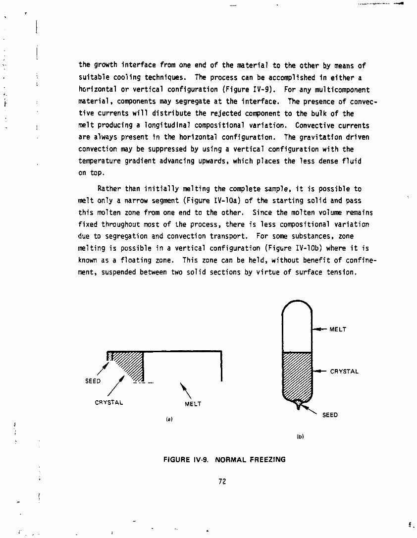
the growth interface from one end of the mater ia l t o the other by means o f
su i tab le cool ing techniques. The process can be accomplished i n e i t h e r a
h ~ r i zontal o r ve r t i ca l configuration (Figure IV-9). For any mu1 ticomponent
material , components may segregate a t the interface. The presence o f convec-
t i v e currents w i l l d i s t r i b u t e the re jected component t o the bulk o f the
m 1 t producing a long i tud ina l compositional var iat ion. Convective currents
are always present i n the hor izontal conf i guration. The g rav i ta t ion dr iven
convection may be suppressed by using a v e r t i c a l conf igurat ion w i t h the
temperature gradient advancing upwards, which places the less dense f l u i d
on top.
Rather than i n i t i a l l y melt ing the complete sample, i t i s possible t o
melt only a narrow segment (Figure IV-lOa) o f the s ta r t i ng s o l i d and pass
t h i s molten zone from one end t o the other. Since the molten volume remains
f i xed throughout most of the process, there i s less compositional va r ia t ion
due t o segregation and convection transport. For some substances, zone
melt ing i s possible i n a ve r t i ca l conf igurat ion (Figure IV-lob) where i t i s
known as a f l o a t i n g zone. This zone can be held, wi thout bene f i t o f confine-
ment, suspended between two s o l i d sections by v i r t u e of surface tension.
SEED f ,
CRYSTAL MELT
MELT
CRYSTAL
Ib)
FIGURE IV-9. NORMAL FREEZING
7 2
' SEED
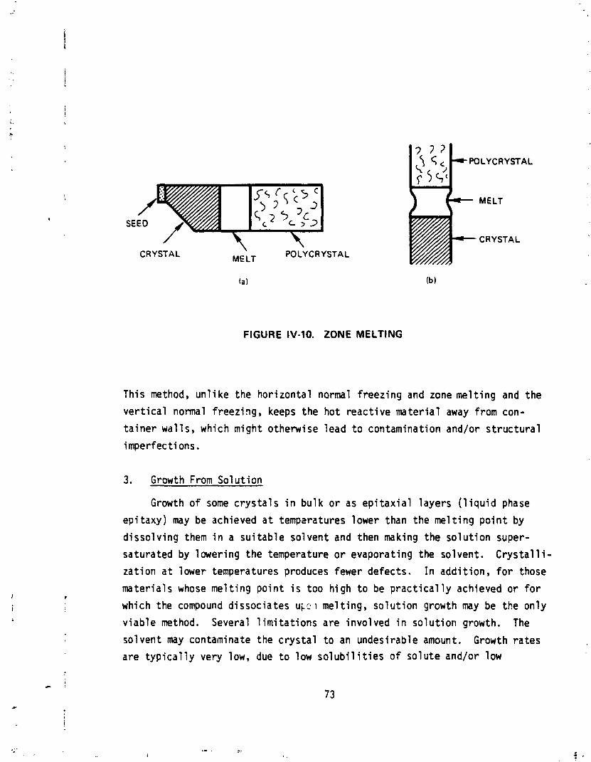
CRYSTAL MELT POLYCRYSTAL
WLYCRYSTAL
MELT
CRYSTAL
FIGURE IV-10. ZONE MELTING
This method, u n l i k e the hor izonta l normal f reezing and zone me1 t i n g and the
v e r t i c a l normal f reezing, keeps the ho t reac t i ve ma te r ia l away from con-
t a i n e r wa l ls , which might otherwise lead t o contaminat ion and/or s t r u c t u r a l
imperfections.
Growth From So lu t i on
Growth of some c r y s t a l s i n bu l k o r as e p i t a x i a l layers ( l i q u i d phase
ep i taxy) may be achieved a t tempsratures lower than the me l t i ng p o i n t by
d i sso l v ing them i n a su i tab le solvent and then making the s o l u t i o n super-
saturated by lower ing the temperature o r evaporat ing the solvent. C r y s t a l l i -
za t ion a t lower temperatures produces fewer defects. I n add i t ion , f o r those
mater ia ls whose me l t i ng p o i n t i s too h igh t o be p r a c t i c a l l y achieved o r f o r
which the compound d issoc ia tes u ~ c l l i mel t ing, s o l u t i o n growth may be the on ly
v iab le method. Several 1 i m i t a t i o n s are involved i n s o l u t i o n growth. The
solvent may contaminate the c r y s t a l t o an undesirable amount. Growth ra tes are t y p i c a l l y very low, due t o low s o l u b i l i t i e s of so lu te and/or low
t ransport rates of solute t o the growth interface. For a1 loy materials the
solvent may be an increased proport ion of a low me1 t i n g po in t component.
Growth of the desired composition requires r i g i d temperature cont ro l t o
prevent s o l i d i f i c a t i o n of an unwanted composition. I n addit ion, the growth
k ine t i cs change as the solute i s used up. Growth and compositional un i fo r -
mi ty may be enhanced i n many mater ia ls by passing a current through the
substrate- l iquid in ter face (electroepitaxy;. This i s an isothermal process
i n which the composition and growth ra te are determined by the substrate
composition, temperature, and appl i ed current density.
4. Growth From a Vapor
Vapor phase methods are slow bu t may produce c rys ta ls o f high p u r i t y
and perfection. These c rys ta ls may be produced on a speci f ic substrate o r
allowed t o nucleate on the container walls. Some methods involve chemical
vapor t ransport i n which some of the c rys ta l components are contained i n a
gaseous chemical compound and are released a t the growth interface by a
chemical reaction. Temperature and compositional cont ro l are most eas i l y
achieved v ia vapor methods.
V . POTENTIAL PROGRAM DIRECTIONS AND THRUSTS
The past several chapters have ind ica ted a considerable uncer ta in ty
i n the product ion of s o l i d s t a t e c r y s t a l s fo r i n f ra red detectbrs. Although
some success has been had w i t h the growth of doped s i l i c o n c r y s t a l s w i t h
a v a r i e t y o f c u t o f f wavelengths (see Fig. 111-I) , the s e l e c t i v i t y ,
espec ia l l y i n the important atmospheric window between 8 and 14 m i c r ~ n s ,
i s n o t good. Binary detectors have a lso shown s i m i l a r important l i m i t s .
The te rnary compounds, on the o ther hand, have shown t h e o r e t i c a l promise
over the f u l l ranye o f condi t ions. The i r drawback has been i n t h e i n a b i l i t y
t o be produced i n appropr iate qua1 i ty , quant i ty , and s i z e t o make complex
de tec tor arrays sensib ly economic.
This e f f o r t a t SPC was o r i g i n a l l y i n i t i a t e d t o develop a case f o r
the u t i l i t y of a low g r d v i t y environment i n a l l e v i a t i n q c r e l i m i n a t i n g
t h i s problem of prodttcing large, homogeneous, defect- f ree s o l i d s t a t e
de tec tor c r y - t a l s i n a wide range cf compositions and shapes. Instead we
have confirmed, i n a somewhat more q u a n t i t a t i v e fashion, one o f t he con-
c lus ions crf the STAMP committee,' t ha t there i s i n s u f f i c i e n t knowledge about
the grorfnd-oased c r y s t a l growth o f s o l i d s t a t e de tec tor ma te r i a l s t o a l l ow
unique q u a n t i f i c a t i o n o f the con t r i bu t i on of reduced g rav i ty -1 nduced segre-
ga t ion ar~d convection on c r y s t a l perfect ion. Quest ions as t o why some of
the c r y s t a l s presently grown on ea r th have exemplary c h a r a c t e r i s t i c s and how
compcsition, t~mpers tu re , geometry, and o ther f ac to rs combine t o prov ide
these "good" samples fron, amongst the bu l k o f poor ma te r i a l a re n o t we l l
understood, l e a s t o f a i l i n those te rnary mater ia ls o f p a r t i c u l a r inser f s t .
a ate rials Processing i n Space, Report of the Corn i t t ee on S c i e n t i f i c and Technological Aspects of Mater ia l s Processing i n Sptce, Space Appl i c a t i o n s Board, Assembly o f Engineering, Nat ional Research Counci 1, NAS: Washington, D . C . , 1978.
75
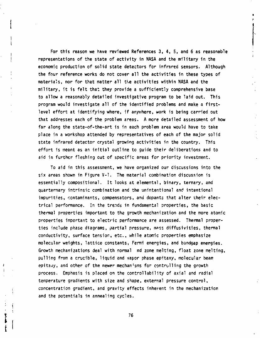
For t h i s reason we have reviewed References 3, 4, 5, and 6 as reasonable
representat ions o f the s t a t e o f a c t i v i t y i n NASA and the m i l i t a r y i n the
economic product ion of so l i d s t a t e detectors fo r i n f r a r e d sensors. A1 though
the f o u r reference works do n o t cover a l l the a c t i v i t i e s i n these types o f
mater ia ls , nor f o r t h a t mat te r a l l the a c t i v i t i e s w i t h i n NASA and the
m i l i t a r y , i t i s f e l t t h a t they prov ide a s u f f i c i e n t l y comprehensive base
t o a l low a reasonably d e t a i l e d i n v e s t i g a t i v e program t o be l a i d out. This
program would i nves t i ga te a l l o f the i d e n t i f i e d problems and make a f i r s t -
l e v e l e f f o r t a t i d e n t i f y i n g where, i f anywhere, work i s being c a r r i e d ou t
t h a t addresses each o f the problem areas. A more d e t a i l e d assessment o f how
fa r along the s ta te-o f - the-ar t i s i n each problem area would have t o take
p lace i n a workshop attended by representat ives o f each o f t he major so l i d
s t a t e i n f r a r e d detec tor c r y s t a l growing a c t i v i t i e s i n the country. This
e f f o r t i s meant as an i n i t i a l o u t l i n e t o guide t h e i r de l i be ra t i ons and t o
a i d i n f u r the r f lesh ing out of spec i f i c areas f o r p r i o r i t y investment.
To a i d i n t h i s assessment, we have organized our discussions i n t o the
s i x areas shown i n F igure V-1. The mater ia l combination d iscussion i s
e s s e n t i a l l y composit ional. I t looks a t elemental, b indry, ternary, and
quarternary i n t r i n s i c combination and the un in ten t i ona l an6 i n t e n t i o n a l
impur i t ies , contaminants, compensators, and dopants t h a t a1 t e r t h e i r e lec-
t r i c a l performance. I n the trends i n fundamental p roper t ies , the basic
thermal p roper t ies important t o the growth mechani za t ion and the more atomic
proper t ies important t o e l e c t r i c performance a re assessed. Thermal proper-
t i e s inc lude phase diagrams, p a r t i a l pressure, masr d i f f u s i v i t i e s , thermal
conduct iv i ty , surface tensioc, etc., w h i l e atomic proper t ies emphasize
molecular weights, l a t t i c e constants, Fermi energies, and bsndgap energies.
Growth mechanizations deal w i t h normal nd zone me1 t i n g , f l o a t zone me1 t i n g ,
p u l l i n g from a c ruc ib le , l i q u i d and vapor phase epitaxy, molecular beam
epi taxy, and o ther of the newer mechantsms fo r c o n t r b l l i n g the growth
process. Emphasis i s placed an the c o n t r o l l a b i l i t y of a x i a l and r a d i a l
temperature gradients w i t h s i z e and shape, ex terna l pressure con t ro l ,
concentrat ion gradient, and g r a v i t y e f f e c t s inherent i n the mechanization
and the po ten t i a l s i n anneal ing cycles.
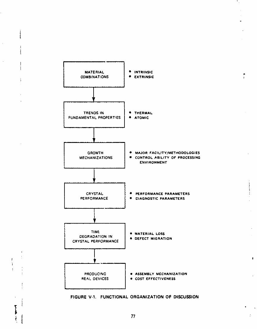
I MATERIAL COMBINATIONS I INTRlI4SIC
EXTRINSIC
I TRENDS IN I THERMAL FUNDAMENTAL PROPERTIES ATOMIC
GROWTH MECHANIZATIONS
MAJOR PAC1 LITY/METHODOLOGIES CONTROL ABILITY OF PROCESSING
ENVl RONMENT
9 +
CRYSTAL PERFORMANCE PARAMETERS ClAGNOSTlC PARAMETERS
I A .re RIAL LOSS CT MIGRATION
TIME MATERIAL LOSS DEGRADATION IN DEFECT MIGRATION
CRYSTAL PERFORMANCE
PRODUCING I ASSEMBLY MECHANIZATION I REAL DEVICES COST EFFECTIVENESS
c FIGURE V-1. FUNCTIONAL ORGANIZATION OF DISCUSSION
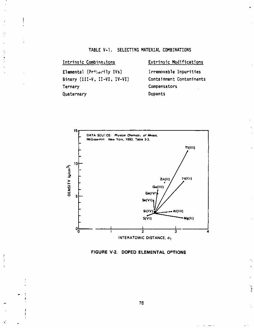
TABLE V-1 . SELECTt NG MATERIAL COMBINATIONS
I n t r i n s l c Combinecions E x t r i n s i c Modi f icat ions
Elemental (Prir , ,ar i ly IVs) f rremovable Impur i t i es
Binary (111-V, 11-VI, IV-VI) Containment Cantami nants
Ternary Compensators
Quaternary Dopants
DATA SOU~ICE: Phvrud Chrrn~rtr~ 01 k(*ta/r, McGraw-Hill: New Y o ~ K , 1953, Tablo 3-3.
l 5 t
t Oo
I I I 1 2 3
INTERATOMIC DISTANCE, d l
FIGURE V-2. DOPED ELEMENTAL OPTIONS
Crysta l performance addresses the e l e c t r i c a l p roper t ies important t o
understanding the device po ten t ia l s and the d iagnost ic measurements necessary
t o assess mater ia l homogeneity and po ten t ia l s f o r t ime delay i n performance.
L i fe t ime i s given special emphasis, both due t o compositional losses from
component v o l a t i l i t y o r f r r chemical lsaching by adjacent mater ia ls and
due t o defect migrat ions from edge e f fec ts o r from adjacent mater ia ls and
j o i n t s . The rea l problem, ttlou$, i s i n the t o t a l device preparat ion
process. Mechanical s i z i n g act ions induce defects, and layer i n g o r junc-
t i o n i n g a c t i v i t i e s can induce a v a r i e t y o f defects. The detec t ion l aye r
i s then only a piece o f the t o t a l system performafice. Out of a l l of t h i s ,
some a t t e n t i o n must be given t o cost ef fect iveness i n terms o f quan t i t y
production, simp1 i c i t y , standardizat ion, and automated va l i d a t ion.
A. SELECTING MATERIAL .';" ;INATIONS
I n evaluat ing mater ia l combinatibns f o r I R d e t e ~ t o r s , i t i s convenient
t o separate i n t r i n s i c and e x t r i n s i c c o n s i d ~ r a t i o n s , as shown i n Table V-1.
The number o f elemental , binary, ternary, and q u a t e r ~ a r y combinations t h a t
make sense t o t ry are ra the r f i n i t e . Many o f these were displaye z a r l i e r
i n F i ~ u r e 111-1. I n addi t ion, the e f f e c t s o f impur i t i es and add i t i ves
a lso have t a be considered.
1. Elemental , Binary, and Ternary Compounds
Figures V-2, V-3, and V-u sumnarize the major p o s s i b i l i t i e s . S i l i c o n
and germanium detectors have been extensively studied, w i t n and wi thout an
ar ray o f dopants. As shown i n Figure V-2, s i l i c o n has been dcped wit.h a i l
of thz appropriate 111 elements and several 11 and V I elements. Germanium
has s i m i l a r l y been studied, but i t provides even less span i n cu to f f wZ*ic-
length number. A1 though there i s much work t h 3 t could be dsse (e. g. ,
Ref. 3) t improve elemental detectors i n t e n s o f (1) l a r g e r sizes, (2)
less contaminanrs i n the i n i t i a l load and f. om the growth processes
containment, (3) less c r y s t a l defects, and ( 4 j mgre homogeneous d i s t r i -
but ions o f dopants apt compensators, i t i s our fee l i ng t h a t i t i s more
important t o look forward t o the more f l ex i b l e ternary compounds. Doped
s i l i c o n and germanium have r i g i d l i m i t s i n the cutoff wavelengths obtain-
able so t ha t there i s inherent ly less adaptab i l i ty i n terms of con t ro l l i ng
the cutc f f wavelengths w i t h i n the narrow graded bands needed f o r the array
detectors desired by NASA and the m i l i t a r y .
The major options for b inary and ternary detectors from 111-V combina-
t i ons i s shown i n Figure V-3. We have p l o t t ed density against interatomic
distance as somewhat simp1 i s t i c subst i tutes f o r the more complex e f fec ts
of gravi ty-dr iven segregation and interelement d i f fus ion o r convection
coeff icients. GaAs and InSb, the two most popular of tiw 111-V b inar i2s
i n t h i s context, are seen t o be made from pa i rs of the most s im i la r atoms.
This means tha t they have less gravi ty-dr iven segregation and d i f f us i on
effects and tend t o d i f f use and convect r e l a t i v e t o each other from thermal
effects i n comparable manners. Thus, these combinations should be the
easiest t o grow and should be the most f ree f r ~ m defects and inhomogenei t i e s
due t o run-control l hb l e g rav i t y and thems l effects. Comparing t h i s w i t h
Figure 111-1 shows t ha t the cutoff wave length generally r i ses w i th a
r i s e i n the bindry density. This implies tha t i t should be important t o
invest igate combinations w i th bismuth and/or tha l l ium (TI ) t o see if the
cu to f f wavelength i s increased i n t o the 8-14 micron atmospheric window.
Once these addi t ional binary compounds are investigated, then the InAsSb
ternary could be used t o f i n e l y d iv ide up the 3-5 micron window and some
ternary combination o f InTlBi , InSbBi, TlSbBi, o r InTlSb might be appro-
p r i a te for f i ne ly breaking up the 8-14 micron window, wi thout the high
sens i t i v i t i e s shown a t one end i n the 111-VI and I V - V I ternary compounds.
Rockwell i s already looking i n t o the InAsSb ternary under an A i r T ~ r c c
Contract and NASA had a Skylab experiment u t i l i z i n g t h i s mater ia l . The
InGaSb compound a1 so appears interest ing. The InSbBi should be s i m i l a r l y
producible if InBi produces higher cutoff wave1 engths, but there may be
some problems due t o the lack o f complete in terso lub i 1 i t y between the two
binar ies. Ternary combinations using P , A1 , or TI may a1 so have some
problems i n crys ta l orowth stabi 1 i ty. I f they show desirable p r o ~ e r t i e s
for pa r t i cu l a r uses, i t might be necessary t o go t o low g rav i t y processing
for these materiai s t o maxiniize the pntent i a l fo r c rys ta l homogeneity.
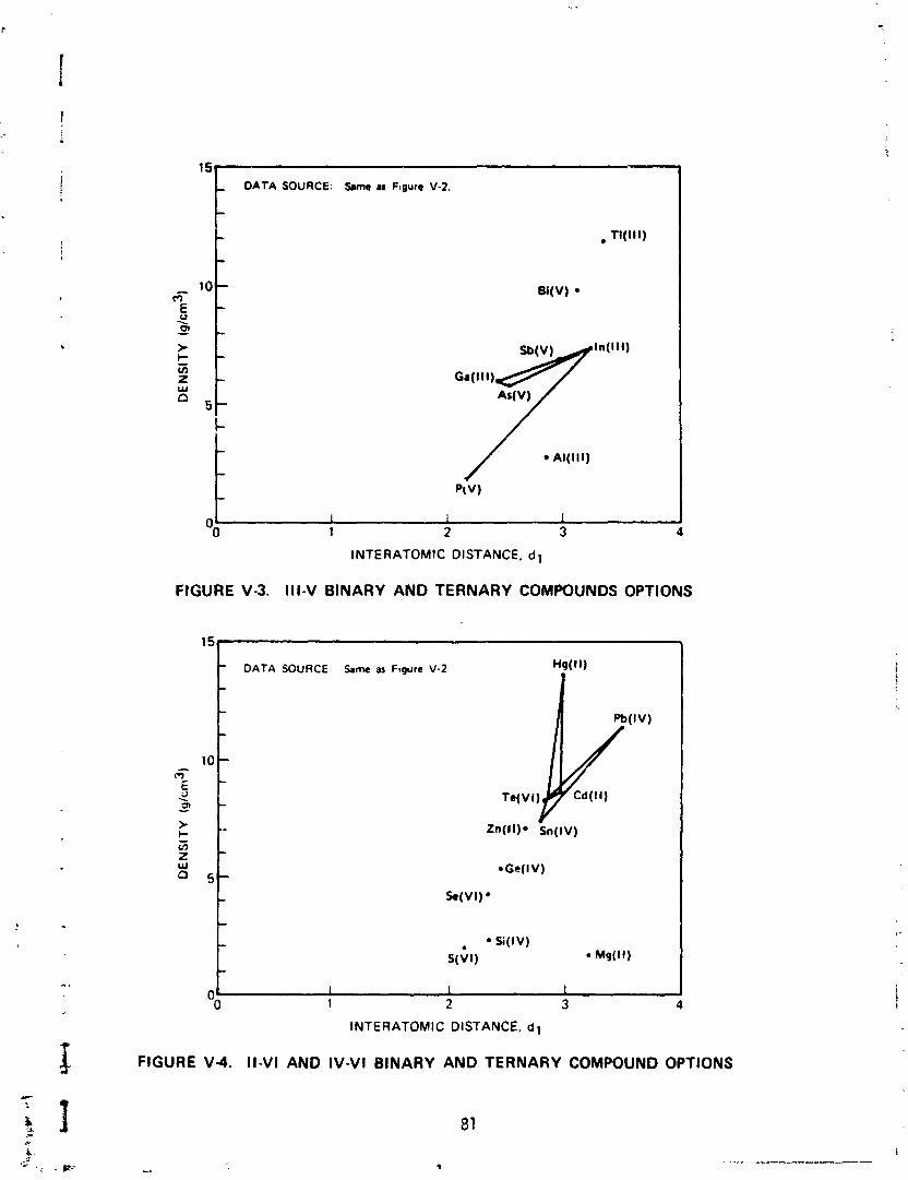
15 - DATA SOURCE: %me r F~gure V-2.
INTERATOMIC DISTANCE. d 1
FIGURE V-3. I l l -V BINARY AND TERNARY COMPOUNDS OPTIONS
DATA SOURCE
INTERATOMIC DISTANCE, d l
FIGURE V 4 . I l -VI AND IV-VI BINARY AND TERNARY COMPOUND OPTIONS
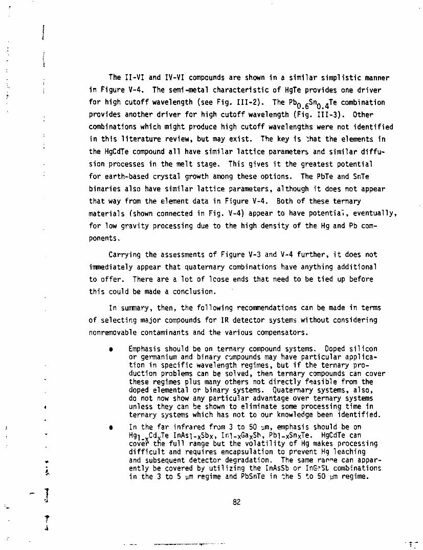
The 11-VI and I V - V I compounds are shown i n a s i m i l a r simp1 i s t i c manner
i n F igure V-4. The semi -metal c h a r a c t e r i s t i c of HgTe provides one d r i v e r
fo r h igh cu to f f wavelength (see Fig. 111-2). The Pbo.6Sn0e4Te combination
provides another d r i v e r f o r h igh cu to f f wavelength (Fig. 111-3). Other
combinations which might produce h igh cu to f f wavelengths were n o t i d e n t i f i e d
i n t h i s l i t e r a t u r e review, bu t may ex i s t . The key i s :hat t he elements i n
t he HgCdTe compound a1 1 have s imi 1 a r l a t t i c e parameters and s imi 1 a r d i f f u -
s ion processes i n the mel t stage. This g ives i t the greates t p o t e n t i a l
f o r earth-based c r y s t a l growth among these opt ions. The PbTe and SnTe
b ina r ies a lso have s i m i l a r l a t t i c e parameters, a1 though it does n o t appear
t h a t way from the element data i n Figure V-4. Both of these te rna ry
mater ia ls (shown connected i n Fig. V-4) appear t o have p o t e n t i a l , eventual ly ,
f o r low g r a v i t y processing due t o the h igh dens i ty of t he Hg and Pb com-
ponents . Carrying the assessments of F igure V-3 and V-4 fu r ther , i t does n o t
imnediately appear t h a t quaternary combinations have anything add i t i ona l
t o o f f e r . There are a l o t o f l cose ends t h a t need t o be t i e d up before
t h i s could be made a conclusion.
I n summary, then, t he fo l low ing recomnendations can be made i n terms
of se lec t i sg major compounds f o r I R de tec tor systems w i thou t consider ing
nonremovabl e contaminants and the var ious compensators.
Emphasis should be on te rnary compound systems. Doped s i l i c o n o r germani um and b inary c~mpounds may have p a r t i c u l a r appl i ca- t i o n i n s p e c i f i c wavelength regimes, b u t i f the te rnary pro- duc t ion problems can be solved, then te rnary compounds can cover these regimes p lus many others no t d i r e c t l y f e a s i b l e from the doped elemental o r b ina ry systems. Quaternary systems, a1 so, do no t now show any p a r t i c u l a r advantage over te rnary systems unless they can be shown t o e l im ina te some processing t ime i n te rnary systems which has no t t o our knowledge been i d e n t i f i e d .
a I n the fa r i n f r a r e d from 3 t o 50 ~ m , emphasis should be on Hgl Cd Te I n A ~ l - ~ s b ~ , Inl-xGaxSh, Pbl-xSnxTe. HgCdTe can c o v 8 t i e f u l l range b u t the v o l a t i l i t y of Hg makes processing d i f f i c u l t and requi res encapsulat ion t o prevent Hg 1 eachi ng and subsequent detector degradation. The same r a v e can appar- e n t l y be covered by u t i l i z i n g the InAsSb o r InG,?St combinations i n the 3 t o 5 pm regime and PbSnTe i n the 5 t o 50 pm regime.
The combination of these several te rnary combinations e l iminates some of the v o l a t i 1 i t y problem, but perhaps trades i t f o r o ther problems.
I n t h e v i s i b l e a n d c o l o r i n f r a r e d r e g i m e (0 .4 -3m) , t h e r e i s much spect ra l absorpt ion d e t a i l f o r ea r th resources app1 i c a t i o n s on renewable and nonrenewable resources, on water and o i l po l l u - t i on , and on atmospheric sounding. It would be appropr iate t o i nves t i ga te te rnary combinations i n t h i s regime a1 so t o replace doped s i 1 icon, and several b inary compounds which genera1 l y have t o be used w i t h complex (and lossy) f i l t e r i n g o r beam s p l i t t i n g arrangements i n order t o ge t f i n e spectra l d e t a i l . Ternary combinations 1 i ke GaNl -xAsx appear t o cover the v i s i b l e regime (0.4-0.7 urn). Al l -x InxAs and Hg1,,CdxTe appear t o cover the near i n f r a r e d o r c o l o r i n f r a r e d regime (0.7-3 pm). Th is area appears t o be p a r t i c u l a r l y important t o future-NASP pro- grams. A l l three mater ia ls have dens i ty va r ia t i ons which may n..cessi t a t e low g r a v i t y processing. GaN has been d i f f i c u l t t o process on earth.
I t should be noted t h a t a substant ia l m a j o r i t y o f the NASA and
m i l i t a r y work i s on HgCdTe combinations. There has x e n some f r e e l i t e r -
a ture e f f o r t on PbSnTe combinations, and Rockwell i s i nves t i ga t i ng InAsSb
combinations f o r the A i r Force (see Ref. 5). More s p e c i f i c assessments
o f p a r t i c u l a r combinations are the subject o f the remainder of t h i s repor t .
We have no t i d e n t i f i e d any s i g n i f i c a n t a c t i v i t y on the use of te rnary
combinations i n the v i s i b l e and near- inf rared regimes out t o 3 ~ m . Th is
should be an important area f o r NASA, but perhaps less important fo r the
m i l i t a r y . Need f o r t h i s lower frequency regime i s one o f the major d i ve r -
gences between c i v i 1 i a n and m i 1 i t a r y requirements and could subs tan t ia l l y
impact the fu tu re Landsat missions f o r NOAA,
2. Impur i t ies , Contaminants, Compensators, and Dopants
I n keeping w i t h our recomnendation t o s t i c k w i t h te rnary combinations,
we w i l l r e s t r i c t our discussion here t o t h a t area. A l l the base mater ia ls
used fo r the ternary combinations suggested f o r study have some l e v e l of
re1 a t i v e l y irremovable impur i t i es l e f t over a f t e r t h n p u r i f i c a t i o n process
i s complete. These somewhat inherent impur i t i es need t o be understood,
ir, p a r t i c u l a r r e l a t i v e t o t h e i r con t r i bu t i on t o the donor/acceptor s i t ua -
t i o n i n the te rnary compound. D i f f e r e n t impur i t i es a r ? present i n each
of t he three base mater ia ls , and the con t r i bu t i ons of these impur i t i es t o
performance unce r ta in t i es needs t o be understood. Honeywell (see Ref. 6) i s s tudying fo r NASA the e f fec ts of s p e c j f i c dopants on Hgl-$dxTe com-
b,inations, where the dopants a re used as compensators. How much of t h i s
compensation i s needed t o a l l ow f o r defects due t o na tu ra l impur i t i es
and how much i s due t o s t r u c t u r a l and s to i ch iomet r i c defects due t o the
growth process i s unknown. Hopefu l ly i t i s small, as normal ly assumed.
I n add i t ion , most o f the growth processes prov ide oppor tun i ty f o r add i t i ona l
contamination due t o the conta iner , t he pressur ized atmosphere, o r the
c a r r i e r f l u i d . These i m p u r i t i e s a lso need assessment through con t ro l l e d
experiments, w i t h known, purposely added v a r i a t i o n s i n a1 1 the i m p u r i t i e s
and contaminants i d e n t i f i e d w i t h a p a r t i c u l a r ma te r i a l source and c r y s t a l
growing technique. The Honeywell e f f o r t f o r NASA has been look ing a t
copper, indium, phosphorus, iod ine, and go ld p r i m a r i l y as compensators.
I n t h i s area we recol. ?lend:
A systematic study o f the q u a n t i t y o f i m p u r i t i e s and contaminants t y p i c a l i n each of the te rnary combinations o f i n t e r e s t . Crys ta ls should then be grown which vary the q u a n t i t y o f each o f the i n - d i v idua l contaminants syster-;;tical l y i n order t o compare t h e i r re1 a t i v e con t r i bu t i ons t o o v e r a l l de tec tor performance.
The Honeywell type o f study on defect chemistry needs t o be expanded t o add i t i ona l dopants and compensators and t o addi- t i o n a l te rnary combinations.
B. MEASURING FUNDAMENTAL MATERIAL PROPERTIES
I n order t o understand the p o t e n t i a l problems inherent i n sny c r y s t a l
growth process, i t i s important t o understand the fundamental t h e m a l and
atom,c proper t ies o f the candidate mater ia ls (e.g., Table V-2 ) . These
t h e m a l and atomic proper t ies s t rong ly in f luence the growth i n te r face
dynamics and the po ten t i a l fo r de fec t o r d i s l o c a t i o n generat ion dur ing t h i s
growth prccess . The only systematic e f f o r t s p resent ly funded i n sol i d s t a t e detectors
are the two e f f o r t s a t McDonnell Douglas and Marquette Un ive rs i t y l i s t e d i n
Table V-3. Both e f f o r t s have tended t o s t ress s to ich iomet r ic compositions,
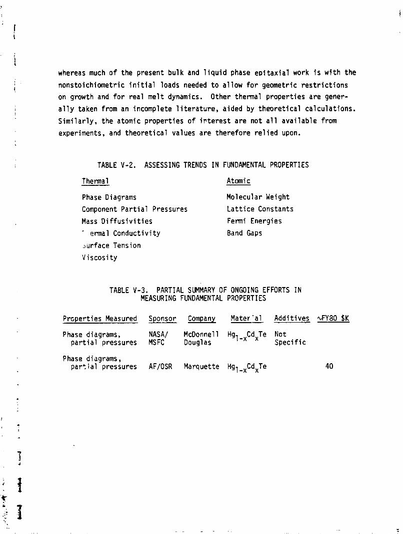
whereas much of the present bu l k and l i q u i d phase e ~ i t a x i a l work i s w i t h the
nonsto ich iometr ic i n i t i a l loads needed t o a l l ow f o r geometric r e s t r i c t i o n s
on growth and f o r rea l me1 t dynamics. Other thermal p rope r t i es are gener-
a l l y taken from an incomplete 1 i t e r a t u r e , aided by theo re t i ca l ca lcu la t ions .
S i m i l a r l y , t he atomic p rope r t i es o f i r t e r e s t a re n o t a l l ava i l ab le from
experiments, and t h e o r e t i c a l values are therefore r e l i e d upon.
TABLE V-2. ASSESSING TRENDS IN FUNDAMENTAL PROPERTIES
Thermal Atomic
Phase Diagrams Molecular Weight
Component P a r t i a l Pressures L a t t i c e Constants
Mass D i f f u s i v i t i e s Fermi Energies
- ermal Conduct iv i ty Band Gaps
~ u r f a c e Tension
V iscos i t y
TABLE V-3. PARTIAL SLP1MARY OF ONGOING EFFORTS IN MEASURING FUNDAMENTAL P2OPERTI ES
Propert ies Measured Sponsor Company -- Mater 'a1 Addi t ives GY80 $K
Phase diagrams, NASA/ McDonnell Hgl -,Cd Je Not p a r t i a l pressures MSFC Doug1 as Spec i f i c
Phase diagrams , par'. i a l pressures AF/OSR Marquette Hgl -,Cd,Te
From t h i s we recomnend tha t :
0 Phase diagram and p a r t i a l pressure measurements be expanded t o inc lude o ther te rnary compounds and both s to i ch iomet r i c and nonsto ich iometr ic combinations. Since NASA i s genera l l y more space and ea r th resources or iented, NASA might use fu l l y empha- s i z e ma te r ia l s f o r the 0.4 t o 3 pm regimes where the m i l i t a r y i s l ess i n t e r ~ s t e d and i n compounds w i thout the mercury, which tends t o be l o s t under space pressures. Th is degrades perfor- mance, e i t h e r from the ma te r ia l l oss o r from the contaminat ion due t o p ressur iza t ion o r from coat ings needed t o a r r e s t t he loss. The m i l i t a r y could cont inue t o emphasize HgCdTe, which promises a more i dea l i zed s o l u t i o n t o t h e i r needs.
0 An effor.. be i n i t i a t e d t o assess the e f f e c t of impur i t i es from natura l o r purposeful sources on key phase diagram character- i s t i c s .
0 The o ther thermal and atomic p rope r t i es cont inue t o have second p r i o r i t y f o r funding u n t i l more evidence f o r spec i f i c ma te r i a l se lec t i on i s gathered from the phase diagram and p a r t i a l pressure e f fo r ts .
. C . EVALUATING CRYSTAL GROWTH MECHANIZATIONS
Understanding the c r y s t a l growth process i s fundamental t o producing
q u a l i t y c rys ta ls . Qua l i t y can be def ined i n several fashions; among
these are:
0 Large-area , somewhat t h i c k c r y s t a l s f o r h igh s e n s i t i v i t y uses needing l a rge focus areas (e.g., astronomic31 and space sensors)
0 Large-volume, rapid-growth bu lk c r y s t a l s f o r sect ion ing and c u t t i n g t o l a r g e q u a n t i t i e s of smal ler sensors (e.g., a r ray sensors)
0 Large-area but con t ro l l ed thinness c r y s t a l s f o r h igh s e n s i t i v i t y o r l aye r ing uses o r f o r e l im ina t ing machining imperfections i n preparing t h i n sensors
m Small-area, h i d , per fec t ion c r y s t a l s f o r 1 im i ted q u a n t i t y uses.
The var ious bu lk and ep, growth techniques discussed e a r l i e r each
have advantages a r disadvantages i n terms of the above d e f i n i t i o n s o f
qua1 i t y . Some cf the major and new techniques of i n t e r e s t are 1 i s t e d i n
Table V-4, along w i t h the major process con t ro l parameters.
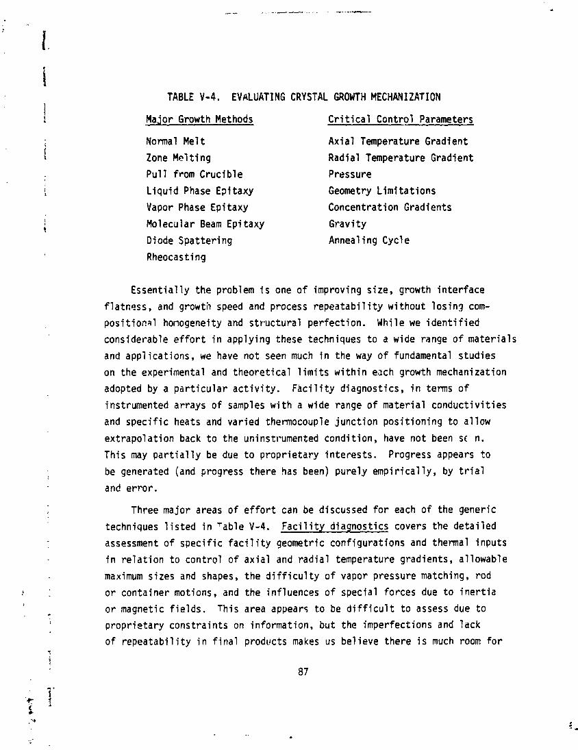
TABLE V-4. EVALUATING CRYSTAL GROWTH MECHANIZATION
Major Growth Methods
Normal Me l t
Zone Me1 t i n g
P u l l from Cruc ib le
L i q u i d Phase E?i taxy
Vapor Phase Epi taxy
Molecular Beam Epi taxy
Diode Spat te r ing
Rheocasti ng
C r i t i c a l Contro l Parameters
Ax ia l Temperature Gradi en t
Radial Temperature Gradient
Pressure
Geometry L i m i t a t i o n s
Concentrat ion Gradients
Grav i ty
Anneal i ng Cycle
Essen t i a l l y the problem i s one of improving size, growth i n t e r f a c e
f latness, and growth speed and process r e p e a t a b i l i t y w i thout l o s i n g com-
posit io,?al honogeneity and st r -uctura l per fec t ion . Whi le we i d e n t i f i e d
considerable e f f o r t i n apply ing these techniques t o a wide range of mater ia ls
and app l ica t ions , we have not seen much i n the way o f fundamental s tudies
on the experimental and t h e o r e t i c a l 1 i m i t s w i t h i n each growth mechanization
adopted by a p a r t i c u l a r a c t i v i t y . ~ a c i l i t y d iagnost ics, i n terms of
instrumented arrays of samples w i t h a wide range o f ma te r i a l conduc t i v i t i es
and spec i f i c heats and var ied thermocouple j unc t i on p o s i t i o n i n g t o a l low
ex t rapo la t i on back t o the uninstrumented condi t ion, have n o t been sc n.
This nay p a r t i a l l y be due t o p rop r ie ta ry i n te res ts . Progress appears t o
be generated (and progress there has been) pure ly emp i r i ca l l y , by t r i a l
and e r ro r .
Three major areas o f e f f o r t can be discussed f o r each of the generic
techniques 1 i s t e d i n l a b l e V-4. F a c i l i t y d iagnost ics covers the de ta i l ed
assessment of s p e c i f i c f a c i l i t y geometric conf igurat ions and thermal f nputs
i n r e l a t i o n t o con t ro l of a x i a l and r a d i a l temperature gradients, a l lowable
maximum sizes and shapes, t he d i f f i c u l t y of vapor pressure matching, rod
o r conta iner motions, and the in f luences o f specia l forces due t o i n e r t i a
o r magnetic f i e l d s . This area appears t o be d i f f i c u l t t o assess due t o
p rop r ie ta ry cons t ra in ts on information, bu t the imperfect ions and lack
of r e p e a t a b i l i t y i n f i n a l products makes us be1 ieve there i s much room f o r
improvement here. Var ia t ions i n product due t o chanqes i n the i n p u t i mater ia ls loaded i n the apparatus are we1 1 repor ted bu t the choice o f
what v a r i a t i o n s t o study has n o t fo l lowed any systematic p lan i d e n t i f i a b l e
i f rcm the 1 i t e r a t u r e we reviewed. Improved understanding o f phase diagrams
as d i s c ~ s s e d c a r l a i e r bould help guide e f fo r t i n t h i s regime. Many specia l
problems 1 i ke g r a v i t y and Marangoni forces, nonsto ich iometr ic s t a r t i n g i mixtures , noncyl i n d r i c a l growth conf igurat ions, and mu1 t i l a y e r 1 ayups have
been studied bu t o f ten appear t o suffer from lack of fundamental under-
standing o f the dynamic processes i n the f a c i l i t y u t i l i z e d . Table V-5
sumnari zes the ongoing ternary-re1 ated growth dynamics e f f o r t s i d e n t i f i e d
from References 3, 4 , 5, and 6.
1. P u l l from a Cruc ib le (e.g., Czor i r a l s k i )
This method i s d i f f i c u l t a t bes t t o apply t o mater ia ls w i t h h igh
vapor pressure ( l i k e mercury) so has no t had much exposure t o te rnary
mater ia l growth. CdTe substrates have been grown and some exp lora tory
s tudies o f InAsSb are under way. We recomnend:
More temperature grad ien t d iagnost ic s tudies i n e x i s t i n g f a c i l i t i e s and i n mod i f i ca t ions which a1 low i n t e r p o l a t i o n of improvements i n p lanar growth; NASA has some i n t e r e s t i n the non-mercury te rna r ies i d e n t i f i e d e a r l i e r and might want t o improve t h e i r understanding o f t h i s growth process.
2. - F loa t i ng Mel t Zone
This area i s no t shown i n Table V-5 s ince i t i s n o t r a s i l y adaptable
t o cope w i t h mercury vapor pressures. Several oi' the te rna ry mater ia ls
i d e n t i f i e d e a r l i e r though may be producib le by the technique, and compari-
t i v e studies would be des i rab le t o assess i t s p o t e n t i a l s r e l a t i v e t o the
pul l - f rom-a-cruc ib le t e c h n i q ~ e . We reccmmend tha t :
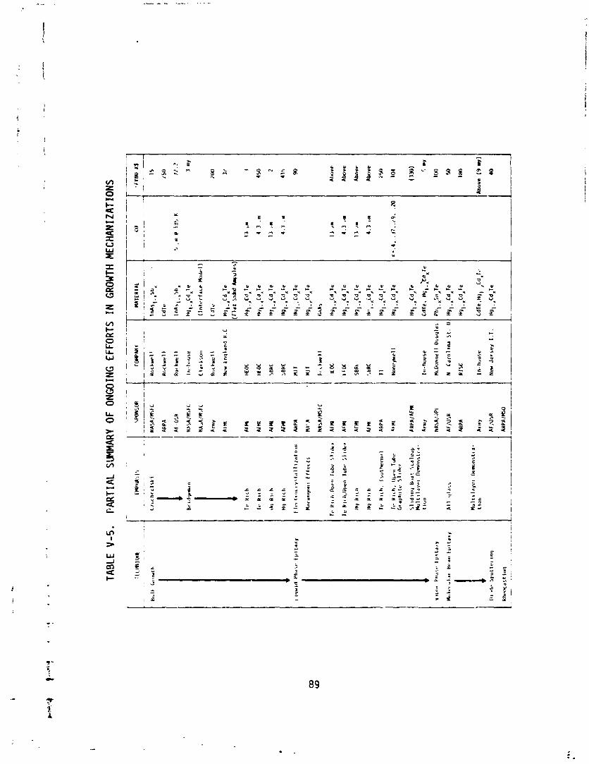
TABL
E 1-
5.
PAR
TIA
L SU
MMAR
Y OF
ONG
OING
EFF
ORT
S IN G
ROWT
H ME
CHAN
IZAT
IONS
IIL
tHII
jIII
-
.-
--
Bu
lk
LII
IWO
~
ARPA
Af -OW
arm
At M
AFM
l
AI C
U
Af ll
ARPA
NA
' A
HA
Mln
SkC
Ai )
(I
AFW
l
Af ll(
MM
I
AkPA
8ll
ll
fim
f
HA
SA
/.JP
I
AF/O
SR
ARPA
WT
ER
IAL
IIIA
S~
-.~
II,
-
CdT
e
InA
,I-,
5bx
HY
,-"C
dx
Tr
(In
tc.r
fdc
e k
bd
rl)
ItO
C
I ro
c
Sem
i
5bRC
TI
Hyl
.x
Cd
,re
In-h
ou
se
C
dT
e.
Hq
I-~
dX
Tr
McO
on
nel
l b
uu
qld
r P
bl-
xS
r~,T
e
N
Cd
ro7
rnr
St.
U
Hy
,-*C
dA
Te
RISE
H
ql-
,,C
dlTe
In- h
ou
se
ficr
Je
rse
y I
.T
I rr
m K
S
---
d;; 700 3,' 450
415 90
Ala
ve
Abo
ve
Abo
ve
&lv
e
ZW
104
(330
)
5 my
IUO
50
180
Abo
ve
(9 30
40
A
0 Some add i t i ona l f a c i l i t y d iagnost ics should be c a r r i e d ou t a t several 1 ocat ions t o de f i ne s p e c i f i c 1 i m i t s on temperature gradients and conf igura t ions . NASA may want t o p a r t i c i p a t e i n t h i s as p a r t o f t h e i r i n t e r e s t 11 l a r g e s i z e detectors f o r space app l ica t ions .
0 Some ternary mater ia l load v a r i a t i o n s a lso need t o be i n v e s t i - gated fo r comparison w i t h the o ther techniques.
0 This technique appears t o prov ide the best mechanism f o r studying Marangoni c i r c u l a t i o n effects. NASA may want t o p a r t i c i p a t e i n t h i s f o r fundamental understanding purposes o r may want t o p lace t h i s on lower p r i o r i t y basis s ince the re are growth techniques w i thout subs tant ia l Marangoni ef fects which might s a t i s f y t h e i r needs.
3 . Contain2d Me1 t s (e.g., Bridqeman)
Bridgeman techniques w i t h conta iner ampules w i t h c a r e f u l l y matched
expansion c o e f f i c i e n t s have shown considerable app l i ca t i on t o the growth
of mercury conta in ing mater ia ls (see Table V - 5 ) . D iagnast ics of the tem-
perature pa t te rns w i t h i n the a m u l e do no t appear very systematic, and good
mathematical representat ions of the thermal and composit ion dynamics 1 i ke
t h a t o f the Clarkson e f f o r t need spec i f i c v e r i f i c a t i o n through carefu l l y
cont r ived tes ts . A wide v a r i e t y of 'new te rnary compounds might a1 so bene-
f it from t h i s technique. The Honeywell (HEOC) and Hughes (SBRC) e f f o r t s
seem f a i r l y comprehensive, but, because of present A i r Force i n t e r e s t i n
a r ray detectors, emphasis appears t o be on the L i q u i d Pk?se Epi taxy p o r t i o n
of t h e i r contract . New England Research Center 's study of f l a t - s i d e d
ampules t o e l im ina te r a d i a l dendr i te growth i s i n t e r e s t i n g bu t i s not
expected t o show much improvement.
We recomnend:
0 That experiments be designed t o v a l i d a t e the Clarkson e f f o r t o r an improvement of it, ana t h a t the technique and v a l i d a t i o n concept be appl i e d t o a wider v a r i e t y of heater configurati-:,IS and ampule mater ia ls and sizes. NASA should p a r t i c i p a t e i n t h i s process i n order t o b e t t e r c a l i b r a t e i ts fac i 1 i t y .
@ That t h i s technique be used t o explore the o ther suggested com- pound candidates and t h e i r b inary components w i t h v o l a t i l e cons t i tuents (e.g., As o r N conta in ing) . This area should be p a r t i c u l a r l y o f i n t e r e s t t o NAS4 s ince the i n i t i a l l y suggested 1 i s t o f candidate te rnary compounds i n the v i s i b l e and near
i n f r a r e d regimes a1 1 conta in p o t e n t i a l l y v o l a t i l e components (e.g., AlInAs, HgCdSe, and GaNAs). I n add i t ion , t h i s may be the p lace t o t e s t the impur i t y and a d d i t i v e compositions found t o be of p a r t i c u l a r i n t e r e s t from the phase diagram s tud ies suggested.
4. Rheocasti n g
The rheocast ing concepts and some v a r i a t i t m s were repor ted i n Reference
5 from A i r Force Ma te r ia l s Laboratory e f fo r t s i n o ther areas. It has some
i n t e r e s t i n g p o t e n t i a l s conceptual ly, b u t w i 11 have t o be evaluated ma te r ia l
by mater ia l t o see i f the d i f f e r e n t i a l forces are s i g n i f i c a n t i n compari-
son w i t h the more na tu ra l phenomena w i t h i n the growth process. NASA might
want t o send someone t o AFML t o evaluate the p o t e n t i a l u t i l i t y o f t h i s
concept.
5. L i q u i d Phase Ep i taxy
There are many d i f f e r e n t concepts which come under t h i s base name.
Under present understanding of growtt-. processes, t h i s generic concept
appears t o have 8dvantage over the bu lk concepts i n terms o f ma te r i a l homo-
genei t y and s t r u c t u r a l per fec t ion . E f f o r t s a t MIT, Honeywell (HEOC) , Hughes (SBRC), Texas Instruments (TI!, and others (see Table V-5) have
shown cont inual improvement i n a rea l s izes and thickness con t ro l and i n tt!s
a b i l i t y t o l a y up m u l t i p l e layers one a f t e r another. The m i l i t a r y i s
considering some scale-up e f f o r t s t o improve output. NASA needs t o p a r t i -
c i pa te i n t h i s e f f o r t 2nd could benef i t from exp lor ing i t s app l i ca t i on t o
o ther mater ia ls .
We recomnend:
That e f f o r t be expended i n b e t t e r de f in ing the near-surface concentrat ion and temperature gradients inherent i n the several a l t e r n a t i v e mechanizations and t o improve and v e r i f y mathematical models o f the f a c i l i t y i n te r faces and l i q u i d and growth dynamics. Because o f the greater imnediate i n t e r e s t and need shown by the m i 1 i ta ry , i t might be b e t t e r fo r NASA t o take a secondary r o l e i n these f a c i l i t y diagnost ics.
0 It i s a lso appropr iate fo r NASA t o explore the f e a s i b i l i t y o f growing some of the o ther te rnary combinations o f i n t e r e s t us ing these techniques.
a M u l t i l a y e r app l ica t ions of t h i s technique appear t o be pa r t i cu - l a r l y promising w i t h appropr iate l a t t i c e matching and growth condi t ions. NASA again might rid:: behind the m i l i t a r y investment w i t h a l i m i t e d subset o f ma te r i a l s which explore o ther spec t ra l regimes of i n t e r e s t t o NASA (e.g., fo r q.4 t o 3 um use).
6. Vapor Phase Epi taxy
Vapor phase ep i taxy su f fe rs most from extreme slowness b u t i s balanced
scmewhat by the p o t e n t i a l f o r very de fec t f ree c r j s t a l s i f one o f ?be
cons t i tuents i s no t h i g h l j v o l a t i l e r e l a t i v e t o the others. 5!(4.5? ,.': . i n t e r e s t i n PbSnTe i s perhaps warranted by t h e i r p lanetary m i , s i r ~ needs.
R e l a t i v e l y small q u a n t i t i e s of h igh p u r i t y ma te r i a l w i t h no s r r ~ i f i c a n t
p o t e n t i a l f o r soace vac;un leaching could prov ide approrv ia te sensor l i f e -
t imes w i thout compromising the performance gains from planar array conf igur-
at ions. InGaSo mater ia ls misbt a lso meet t h i s ;I i t e r i a . We recomnend
t h a t NAS4 cont inue t o explore t h i s area fo r low-quant i ty , h igh -qda l i t y
app l ica t ions .
7. Molecular Beain Epi taxy and Diode S p u t t e r -
Both these techniques appear t o be i n the exp lora tory f e a s i b i l i t y
phases o f development w'th moderate Air Forace, Arm:), and AHPA investment.
We d i d no t look a t these techniques i n ecouyc depth t~ make recommendations.
D. ASSESSING MATERIPL PERFORMANCE FOR DETECTIOfi APVLICATlONS
This area addresses the necd t o tinderstand the quai i t,f of the c r y s t a l s
produced, no t on ly i n terms o f t h e i r d e t e c t i ~ i i c l laractcr f s t i c s , bu t a lso
i n terms r e l a t i n g these proper t ies t o t h e i r molecular acd st ructur1al per-
fect ion. Table V-6 l i s t s some o f the key parameters foi* whic? tucnniques
need t o be developed t o prov ide t h e i r measuremerrt. F'lany o f ?h.t e f f o r t s
l i s t e d i n Table V - 5 have scbne o f these c a p a b i l i t i e s inherent f r, tn2 scmpan;
e f fo r t s t o de f ine t t 'e i r ~ r o d u c t s . Table V-7 lists thase performa, ,e
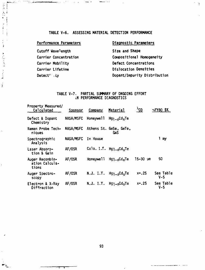
TABLE V-6. ASSESSING MATERIAL DETECTION PERFORMANCE
Performance Parameters Diaqnostic Parameters
Cutoff Wave1 ength
Carr ier Concentration
Carr ier Mobi 1 i t y
Carr ier L i fe t ime
Detect'. i;y
Size and Shape
Canposi t i ona l Homogeneity
Defect Concentrations
Dis locat ion Densit ies
Dopant/Impuri t y D i s t r i bu t i on
TABLE V-7. PARTIAL SUMMARY OF ONGOING EFFORT i N PERFORMANCE DIAGNOSTICS
Property Measuredl Calculated Sponsor Company Mater ia l - 'CO GY80 $K
Defect & Dopant NASAIMSFC Honeywell Hgl ,,CdXTe Chemistry
Raman Probe Tech- NASAIMSFC Athens S t . GeSe, GeTe, niques Gas
Spectrographic NASAIMSFC I n Rouse Analysis
Laser Absorp- AFIOSR Cola. I .T. Hgl ,,CdxTe t i o n & Gain
Auger Recombi n- AFIOSR Honeywell Hgl,xCdxTe 15-30 vm 50 a t ion Calcula- ti ons
Auger Spectro- AFIOSR N.J. I ,T. Hgl,,Cd,Te x=.25 See Table SCOPY V- 5
Electron & X-Ray AFIOSR N.J. I.T. Hg1-,CdxTe xz.25 See Table D i f f r ac t i on 1-5
diagnostic efforts which were speci f ical ly ident i f ied i n References 3
through 6. The Honeywell a c t i v i t y on defect and dopant chemistry appears
t o provide an excel l en t s t a r t towards detai led understanding of molecular
effects on e lec t r i c performance. Attempts were made t o understand devia-
t ions from s t o i c h i m t r y , the nature of the l a t t i c e defects, the mechanisms
by which dopants are incorporated and affect defects, and the thermodyna-
mics of defects, through both experiment and theory. Special at tent ion
was given t o preparation o f undoped and doped samples and for measuring
f ina l atomic characterist ics by as many methods as prac t ica l l y possible
wi th available funding. Most o f the other efforts l i s t e d i n Table V-7 address par t icu lar diagnostic techniques. The lack of systematic diagnos-
t i c s i n t h i s area has hindered the a b i l i t y t o d i rec t changes i n growth
techniques i n order t o work around undesi rabl e trends. Considerable
e f fo r t i s warranted i n t h i s area.
We recomnend:
0 An expansion o f the type o f e f fo r t i n i t i a t e d by Honeywell f o r NASA t o systematically assess the products from the various growth techniques i n order t o a id both better selection o f materi a1 s and better design o f faci 1 i t i e s t o eliminate process derived inhomogeneities. Although NASA has made a good s ta r t on HgCdTe, i t may be more appropriate t o investigate other materials wi th more long-range NASA importance along the 1 ines previously discussed.
An e f f o r t should be made t o systematically 3ssess and categorize a l l the diagnostic tools f o r determining atomic composition and l a t t i c e imperfections. The re la t i ve value, now and potent ia l ly i n the future, needs t o be assessed from both performance and investment standpoints. Several concepts should be chosen for development t o support both research needs and the val idat ion concepts useful i n production qua l i t y control. A l l who have need f o r repeatabi 1 i tj and qua1 i t y assurance could benef i t from invest- ment -in t h i s often-neglected aspect.
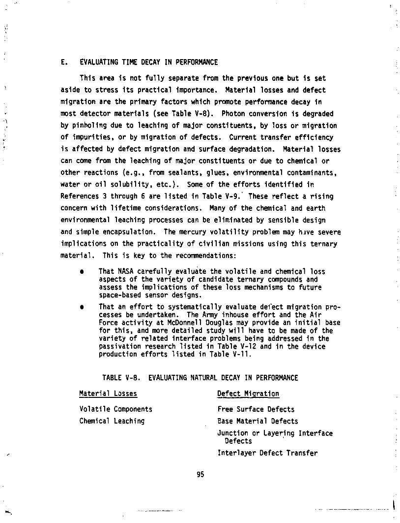
E. EVALUATING TIME DECAY IN PERFORMANCE
This area i s not f u l l y separate from the previous one but i s set
aside t o stress i t s p rac t i ca l importance. Mater ia l losses and defect
migrat ion are the primary factors which promote performance decay i n
most detector mater ia l s (see Table V-8). Photon conversion i s degraded
by pinhol ing due t o leaching of major constituents, by loss o r migrat ion
o f impur i t ies, o r by migrat ion of defects. Current transfer ef f ic iency
i s af fected by defect migrat ion and surface degradation. Mater ia l losses
can come from the leaching o f major consti tuents o r due t o chemical o r
other reactions (e.g., from sealants, glues, environmental contaminants,
water o r o i l so l ub i l i t y , etc.). Some o f the ef for ts i d e n t i f i e d i n
References 3 through 6 are 1 i s t ed i n Table V-9.' These r e f l e c t a r i s i n g
concern w i th l i f e t ime considerations. Many of the chemical and earth
environmental leaching processes can be el iminated by sensible design
and simple encapsulation. The mercury v o l a t i 1 i t y problem may h ~ v e severe
imp1 icat ions on the p r a c t i c a l i t y o f c i v i l i a n missions using t h i s ternary
material. This i s key t o the recomnendations:
That NASA care fu l l y evaluate the v o l a t i l e and chemical loss aspects o f the va r ie ty o f candidate ternary compounds and assess the impl icat ions o f these loss mechanisms t o fu tu re space-based sensor designs.
That an e f f o r t t o systematical ly evaluate defect migrat ion pro- cesses be undertaken. The Amy inhouse ef for t and the A i r Force a c t i v i t y a t McDonnell Douglas may provide an i n i t i a l base for th is , and more deta i led study w i l l have t o be made o f the va r ie ty o f re1 ated in ter face problems being addressed i n the passivation research l i s t e d i n Table V-12 and i n the device production e f f o r t s l i s t e d i n Table V-11.
TABLE V-8. EVALUATING NATURAL DECAY IN PERFORMANCE
Material Losses Defect M i q ra t ion
Vo la t i l e Components Free Surf ace Defects
Chemical Leaching Base Mater ia l Defects
Junction o r Layering Interface Defects
In te r1 ayer Defect Transfer
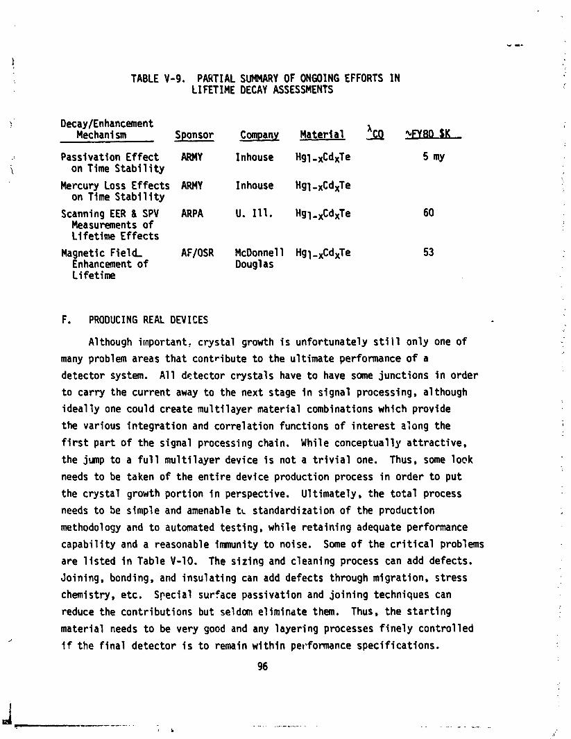
TABLE V-9. PARTIAL SUMMARY OF ONGOING EFFORTS IN L I FETIME DECAY ASSESSMENTS
\ Decay/En hancement Mechani sm Sponsor C a n Material 'FYN $K
... Passivation Effect ARMY Inhouse Hgl -XCdxTe i on Time S t a b i l i t y
Mercury Loss Effects ARMY Inhouse Hgl -xCdxTe on Time S t a b i l i t y
Scanning EER 8 SPV ARPA U. 1 Hg~,~cd~Te 60 Measurements o f Lifet ime Effects
Magnetic F ie ld, AF/OSR McDonnell Hgl -xCdxTe Enhancement of Doug1 as Lifet ime
F. PRODUCING REAL DEVICES
Although important, crystal growth i s unfortunately s t i i 1 only one of
many problem areas tha t contribute t o the ul t imate performance of a
detector system. A l l detector crystals have t o have some junctions i n order
t o carry the current away t o the next stage i n signal processing, although
ideal l y one could create mu1 t i 1 ayer material combinations which provide
the various in tegrat ion and correlat ion functions o f in te res t along the
f i r s t part o f the signal processing chain. While conceptually at t ract ive,
the jump t o a f u l l mul t i layer device i s not a t r i v i a l one. Thus, some lock
needs t o be taken of the en t i re device production process i n order t o put
the crystal growth port ion i n perspective. Ult imately , the t o t a l process
needs to be simple and amenable t~ standardization o f the production
method01 ogy and t o automated test ing , whi 1 e reta in ing adequate performance
capabi l i ty and a reasonable immunity t o noise. Some of the c r i t i c a l problems
are l i s t e d i n Table V-10. The s iz ing and cleaning process can add defects.
Joining, bonding, and insulat ing can add defects through migration, stress
chemistry , etc. Special surface passivation and jo in ing techniques can
reduce the contributions but seldom eliminate them. Thus, the s ta r t i ng
material needs t o be very good and any layering processes f ine ly control led 2
!f the f i n a l detector i s t o remain w i th in perbformance specif ications.
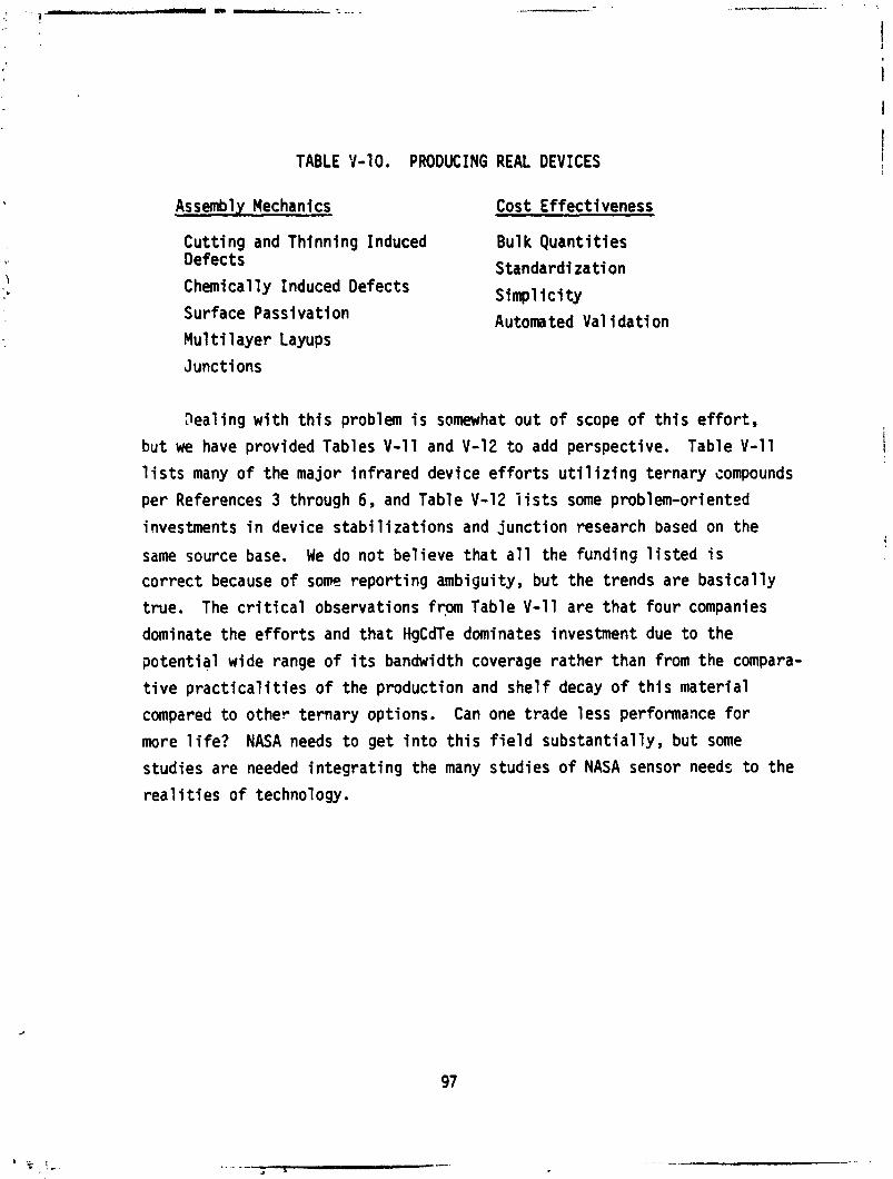
TABLE Y-10. PRODUCING REAL DEVICES
Assembly Mechanics Cost Effectiveness
Cutt ing and Thinning Induced Bulk Quant i t i es Defects Standardization Chemically Induced Defects Simp1 i c i t y Surface Passivation Automated Val i d a t i on Mu1 t i 1 ayer Layups
Junctions
Dealing w i t h t h i s problem i s somewhat out of scope of t h i s effort,
but we have provided Tables V-11 and V-12 t o add perspective. Table V-11
1 i s t s many of the major in f ra red device e f f o r t s u t i l i r i n g ternary compounds
per References 3 through 6, and Table V-12 i i s t s some problem-orientcd
investments i n device stabi l i za t i ons and junct ion research based on the
same source base. We do not bel ieve tha t a l l the funding l i s t e d i s
cor rect because of some report ing ambiguity, but the trends are bas ica l ly
true. The c r i t i c a l observations fr,m Table V-11 are t ha t four companies
dominate the e f f o r t s and t ha t HgCdTe dominates investment due t o the
potent ia l wide range o f i t s bandwidth coverage ra ther than from the compara-
t i v e p r a c t i c a l i t i e s o f the production and she l f decay of t h i s material
compared t o other ternary options. Can one t rade less performance for
more l i f e ? NASA needs t o get i n t o t h i s f i e l d substant ia l ly , but some
studies are needed in tegrat ing the many studies o f NASA sensor needs t o the
r e a l i t i e s o f technology.
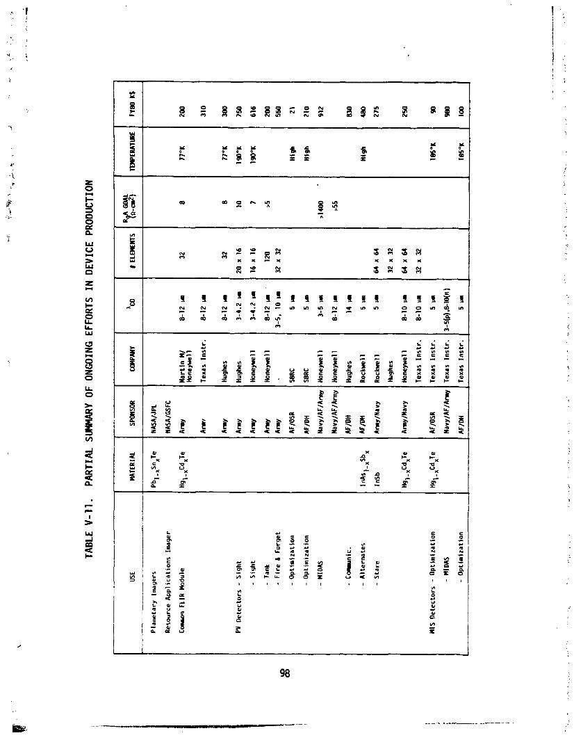
TABL
E V-
11.
PAR
TIA
L SU
MM
ARY
OF
ONG
OIN
G E
FFO
RTS
IN D
EVIC
E PR
ODU
CTIO
N
Pla
ne
tary
Im
ager
s
Res
ou
rce
Ap
pli
ca
tio
ns
Im
ager
C-s
FLlR
Mod
ule
PV
De
tec
tors
- S
igh
t
- S
igh
t
- Ta
nk
- Fir
e 6
F
org
et
- O
pti
ni z
ati
oa
- O
pti
miz
ati
on
HIS
De
tec
tors
- O
pti
miz
ati
on
- M
IDA
S
L
- O
pti
miz
ati
on
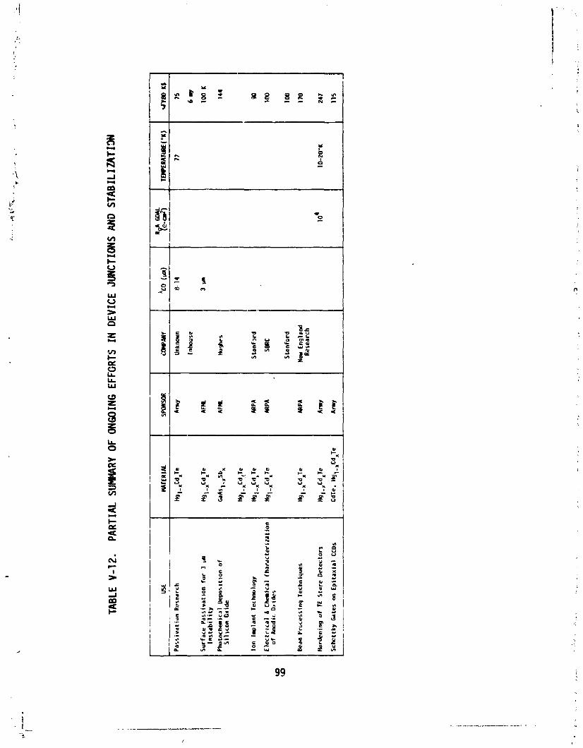
TABL
E V-
12.
PART
IAL
SU
MR
Y O
F ON
GOIN
G EF
FGRT
S IN
DEV
ICE
JUNC
TIO
NS A
ND S
TAB
ILIZ
ATI
M
REFERENCES
1. D. Long. "Photovol t a i c and Photoconductive In f ra red Detectors" i n Optical and I R Detectors, R. J. Keyes, ed., Springer-Verlag, Ber l in , 1977.
2. I. Nelngai l is and T. C. Harman, Semiconductors and Semimetals, Vol . 5, R. Willardson and A. Beer, eds., Academic Press, New York, 1 9 0 ,
3. Natf anal Materials Advisory Board, "U l t ra High Pu r i t y Si l icon, Report 356, 1980.
4. H. C. G a t e s e t a l . , " P r e s e n t s t a t u s o f GaAs,"NASAContractorReport 3093, 1979.
. Minutes o f National Research Council Comission on Sociotechnical Systems, "Comni t t ee on Assessment o f Current HgCdTe Production Technology ," December 1979.
6. Second STS Science Review, Marshall Space F l i g h t Center, A p r i l 22-23, 1979.
PERTINENT PUBLICATIONS
1. W. Bardsley e t al., eds., Crysta l Growth: A Tu to r ia l Approach, North-Hol land, 1979.
2. B. B a r t l e t t e t a1 . , "Growth and Propert ies of CdxHgl-xTe Crystals ," J. Mat. Science, 4 (1969) 266.
3. B. B a r t l e t t e l al., "The Ef fec ts o f Growth Speed on the Compositional Var iat ions i n Crystals o f Cadmium Mercury Tel lur ide," J. Crys. Growth, 47 (1979) 341. -
4. B. B a r t l e t t e t a1 . , "A Study of Casting i n the Cd,Hgl-,Te System," J. Crys. Growth, 47 (1979) 341.
5. M. M. Blouke ec al., "Sens i t i v i t y L imi ts f o r Ex t r i ns i c and I n t r i n s i c Inf rared Detectors," In f ra red Phys., 13 (1973) 61.
6. R. Brebrick and A. Strauss e t a l . , "Par t ia l Pressures o f ~ g ( g ) and Te (a) i n Hg-Te System From Opti'cal Densities," J . Phys. Chem. Sol ids 26' (1965) 98a. -
7. C. E l 1 i o t , " I n t r i n s i c Carr ie r Concentration i n Semiconducting Cd,Hgl-Je Alloys," J. Phys. D: Appl. Phys., - 4 (1971) 697.
8. C. E l l i o t e t al., "Carr ier Freeze-out and Acceptor Energies i n p-type
Hgl-x CdxTe," J. Phys. Chem. Solids, 21 (1972) 1527.
E. Igras e t a1 . , "Ultimate De tec t i v i t y o f (CdHg)Te In f ra red Photoconduc- tors," In f ra red Phys., 19 (1979) 143.
E. Johnson and J. Schmit, "Doping Propert ies of Selected Impur i t ies i n Cd Te," J. Elec. Mat., 5 (1977) 25. Hgl-x *
R. J. Keyes, ed., Opt ical and In f ra red Detectors, Springer-Verlag, 1977.
R. H. Kingston, Detect ion o f Opt ical and Infrared Radiation, Springer- Verlag, 1978.
M. A. Kinch e t al . , "Recombination Mechanisms i n 8-14vm HgCdTe," J. Appl. Phys., 44 (1973) 1649.
M. A. Kinch e t al., "0.1 eV HgCdTe Photodetectors," In f ra red Phys., - 15 (1975) 111.
,
15. F. A. Kroger, The Chemistry of Imperfect Crysta ls , Vols. 1-3, North- Holland, 1973.
16. M. L a n i r e t al., "EBIC Character izat ion of HgCdTe Crysta ls and Photo- diodes," J. Elec. Mat., 8 (1979) 175.
17. M. Lan i r e t a1 . , "Backside-Il luminated HgCdTe/CdTe Photodiodes," Appl . Phys. Le t te rs , 34 (1979) 50.
18. D. Long, "Calculat ion of Ionized-Impuri ty Scat te r ing M o b i l i t y o f Elec- t rons i n Hgl-xCdxTe,ll Phys. Rev., 176 (1968) 923.
D. Long, "Uniformity of I n f r a r e d Detector Parameters i n A l l o y Semicon- ductors ," Inf rared Phys., 12 (1972) 115.
H. Matare, Defect E lec t ron ics i n Semiconductors, W i ley-Interscience, 1971.
J. M. Pawlikowski and P. Becla, "Some Propert ies of Photovol ta ic CdxHgl-,Te Detectors f o r I n f r a r e d Radiat ion ,I1 I n f r a r e d Phys. , 15 (1975) 331.
J . S c h i t and C. Speerschneider , "Phase Diagram o f Hgl-,CdxTe," I n f r a r e d Phys., - 8 (1968) 247.
J. Schni t and E. Ste lzer , "The Ef fec t o f Annealing Temperature on the Car r i e r Concentration of Hg0.6Cd0.4Te,11 J. Ele;. Mat., 1 (1978) 65.
J. Schmit and J. Bowers, "LPE Growth o f Hg0.6Cd0.40Te From Te-Rich Solu- t i o n ,I1 Appl . Phys. Le t te r , 35 (1 979). 457.
W. Scot t and R. Hager, llAnomalous E l e c t r i c a l Propert ies o f p-Type Cd Te," J. Appl. Phys.,% (1971) 803. "gl-x x
W. Scot t e t a1 . , " E l e c t r i c a l and Far-Infra>-ed Opt ica l Propert ies o f p-Type Hgl_xCdxTe," J. Appl . Phys., 47 (1976) 1408.
W. Scott , I1Electron Mobi 1 i t y i n Hgl-,Te," J. Appl . Phys. , 3 (1972) 1055.
A. Strauss and R. Brebr i ck, "Vapor-Crystal Equi 1 i brium and E l e c t r i c a l Propert ies of HgTe," J. Phys. Chem. Sol ids, 31 (1970) 2293.
W. Shockley and W , T. Read, Jr., " S t a t i s t i c s of t h e Recombinatfons of Holes and Elsctrons ," Phys. Review, 87 (1952) 835.
0. Tu f te and E. S te lzer , "Growth and Propert ies of Hgl-,CdxTe E p i t a x i a l Layers," J. Appl . Phys. , 3 (1969) 4559.
P. Vohl and C. Walfe, "Vapor Phase Growth of Hgl-xCdxTe E p i t a x l a l Layers ,I1
J. Elec Mat,, 1 (1978) 659.
32. R. K. W i l lardson and A. C. Beer, eds., mic conductors and Semimetal s, Vol. 5, I n f r a r e d Detectors, Academic Press, 1970,
33. R. K. Willardson and A. C. Beer, eds., Semiconductors and Semimetals, Vol . 12, I R Detectors 11, Academic ".-zs51;7[87$.