H Flume Users Manual - Openchannelflow · The flume combined the flow sensitivity of a narrow angle...
17
i H Flume User’s Manual HS/H/HL FLUME User’s Manual
Transcript of H Flume Users Manual - Openchannelflow · The flume combined the flow sensitivity of a narrow angle...

i H Flume User’s Manual
HS/H/HL FLUME
User’s Manual

TABLE OF CONTENTS
Introduction to the H Flume .............................................................. 1
Development ................................................................................ 1
Function ...................................................................................... 2
Design ........................................................................................ 2
Standards .................................................................................... 3
Accuracy ..................................................................................... 3
Dimensions .................................................................................. 4
Dimensional Tolerances ................................................................... 4
Points of Measurement .................................................................... 6
Flow Equations .............................................................................. 6
Submerged Flow ............................................................................ 7
Submergence Transition ................................................................... 8
Submerged Flow Equations ............................................................... 8
Where to Install a H Flume .............................................................. 10
Upstream of the Flume .................................................................. 10
Flume Location ............................................................................ 11
Downstream of the Flume ............................................................... 11
How to Install a H Flume ................................................................ 12
Bracing the Flume ........................................................................ 12
Connection Joints ........................................................................ 13
How to Maintain a H Flume ............................................................. 13
Channel Inspection ....................................................................... 13

Flow Inspection ........................................................................... 14
Flume Inspection ......................................................................... 14

1 H Flume User’s Manual
INTRODUCTION TO THE H FLUME
The H series of flumes are more modified weirs than they are true flumes – with a V-
shaped throat and no diverging / discharge section. The H flume design allows a wider
range of flows than any other flume type – providing low flow sensitivity as well as the
ability to measure high flow rates. Applications such as edge-of-field runoff monitoring
that have low average flows and substantially higher rain even flows are idea
candidates for H flumes.
The flat floor of the H flumes means that it passes sediments and smaller debris fairly
easily. However, smaller HS / H flumes are generally not recommended for use on
flows containing sanitary solids or larger debris as these can lodge in the narrow
discharge of the flume.
While originally developed for agricultural runoff monitoring, the versatility of the H
flume has seen it used in a number of different applications:
• Edge-of-field monitoring
• Watershed monitoring
• Dam seepage
• Industrial discharge monitoring
• Sewage treatment plants (screened / treated flows)
• Spring
DEVELOPMENT
The Dust Bowl experience of the 1930’s saw the establishment of the Soil Conservation
Service in 1935. Their mandate was to conserve the nation’s soil and water resources.
With this mandate, the researches of the SCS began the investigation and
development of a class of flumes suitable for measuring agricultural flows.
The result was the H flume, so called because it was the eight in a series of flumes
investigated. The flume combined the flow sensitivity of a narrow angle V-notch weir
with the flat floor and self-cleaning properties of a flume.
2 H Flume User’s Manual
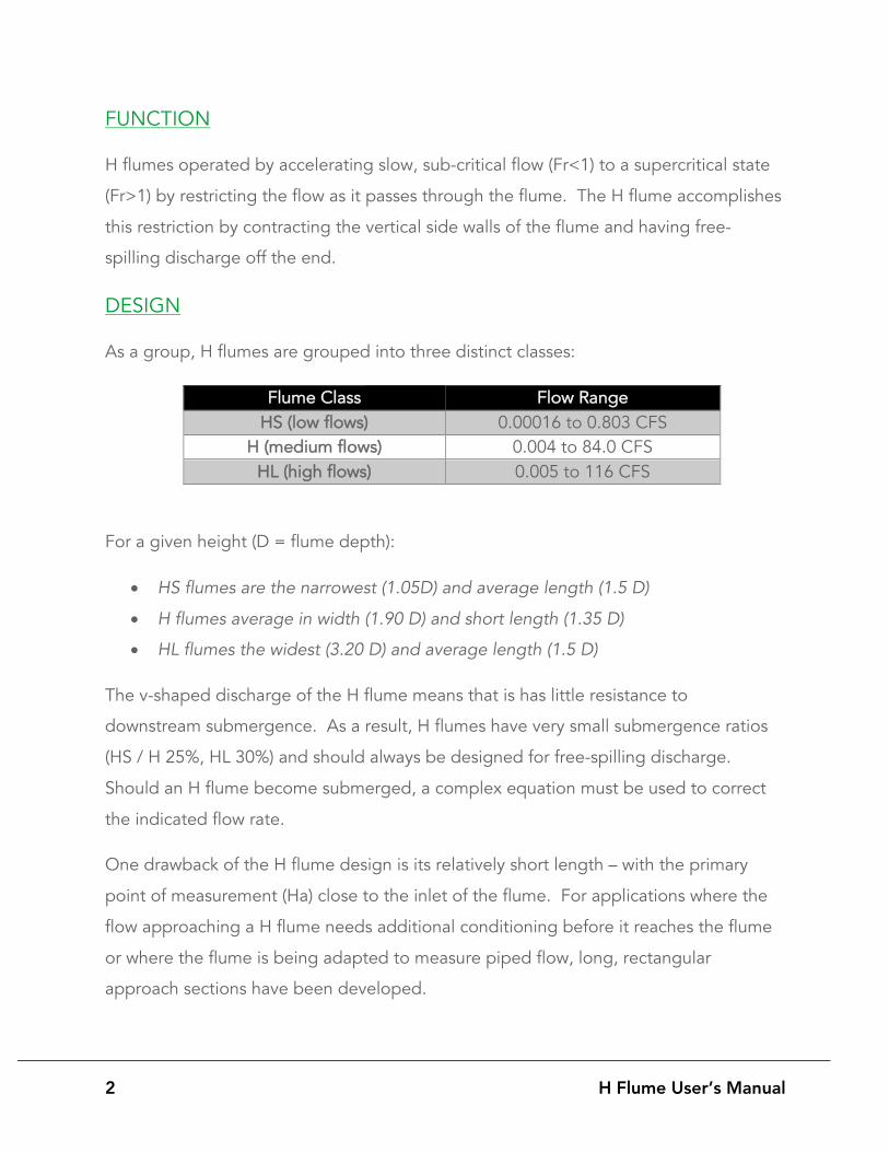
FUNCTION
H flumes operated by accelerating slow, sub-critical flow (Fr<1) to a supercritical state
(Fr>1) by restricting the flow as it passes through the flume. The H flume accomplishes
this restriction by contracting the vertical side walls of the flume and having free-
spilling discharge off the end.
DESIGN
As a group, H flumes are grouped into three distinct classes:
Flume Class Flow Range HS (low flows) 0.00016 to 0.803 CFS
H (medium flows) 0.004 to 84.0 CFS HL (high flows) 0.005 to 116 CFS
For a given height (D = flume depth):
• HS flumes are the narrowest (1.05D) and average length (1.5 D)
• H flumes average in width (1.90 D) and short length (1.35 D)
• HL flumes the widest (3.20 D) and average length (1.5 D)
The v-shaped discharge of the H flume means that is has little resistance to
downstream submergence. As a result, H flumes have very small submergence ratios
(HS / H 25%, HL 30%) and should always be designed for free-spilling discharge.
Should an H flume become submerged, a complex equation must be used to correct
the indicated flow rate.
One drawback of the H flume design is its relatively short length – with the primary
point of measurement (Ha) close to the inlet of the flume. For applications where the
flow approaching a H flume needs additional conditioning before it reaches the flume
or where the flume is being adapted to measure piped flow, long, rectangular
approach sections have been developed.

3 H Flume User’s Manual
Approach sections are usually 3 to 5 times the maximum anticipated head (Hmax) in
length. As a default, Hmax is usually assumed to be the flume’s depth.
For example: a 1.0-foot H flume would have an approach 3 to 5-feet long (3-5D).
Note that when using H flumes with approach sections on flow streams is a high solids
content (or larger solids), sedimentation may occur in the approach section. Here,
sloped floors have been used to direct the flow to one side of the flume, with minimal
change in flow accuracy.
STANDARDS
There are no national / international standards for H flumes.
The dimensions for the HS / H / HL flumes are presented in two primary publications:
• Brakensiek, D., Osborn, H., Rawls, W., Field Manual for Research in Agricultural
Hydrology, Agriculture Handbook No. 224, United Department of Agriculture,
February 1979
• Gwinn, W., Parsons, D, Discharge Equations for HS, H, and HL Flumes, Journal
of the Hydraulics Division, Vol. 102, No. 1, 1976
While the dimensions for approach sections was presented in:
• Gwinn, W., Chute Entrances for HS, H, and HL Flumes, Journal of Hydraulic
Engineering, May 1984
ACCURACY
In Discharge Measurement Structures, Bos presents the unified flow equation for H
flumes as accurate to within +/- 3%.
Other sources provide precision ranges from +/-2-5%.

4 H Flume User’s Manual
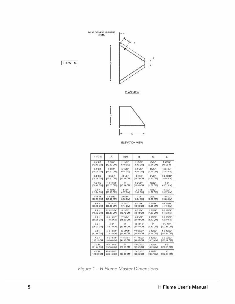
DIMENSIONS
The master dimensions for H flumes are found in Figure 1.
DIMENSIONAL TOLERANCES
To date, there has been no published information on the dimensional tolerances
required for H flumes, but given their low flow sensitivity, the dimensions for the flume
themselves should be at least +/-2%, and better if possible.
Note that unlike the flume, strict dimensional accuracy is not required in the
construction of the approach section.
5 H Flume User’s Manual
Figure 1 – H Flume Master Dimensions
6 H Flume User’s Manual
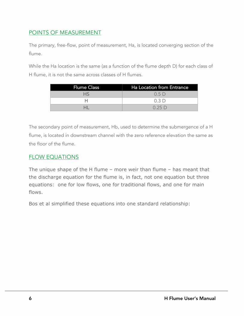
POINTS OF MEASUREMENT
The primary, free-flow, point of measurement, Ha, is located converging section of the
flume.
While the Ha location is the same (as a function of the flume depth D) for each class of
H flume, it is not the same across classes of H flumes.
Flume Class Ha Location from Entrance HS 0.5 D H 0.3 D HL 0.25 D
The secondary point of measurement, Hb, used to determine the submergence of a H
flume, is located in downstream channel with the zero reference elevation the same as
the floor of the flume.
FLOW EQUATIONS
The unique shape of the H flume – more weir than flume – has meant that the discharge equation for the flume is, in fact, not one equation but three equations: one for low flows, one for traditional flows, and one for main flows.
Bos et al simplified these equations into one standard relationship:
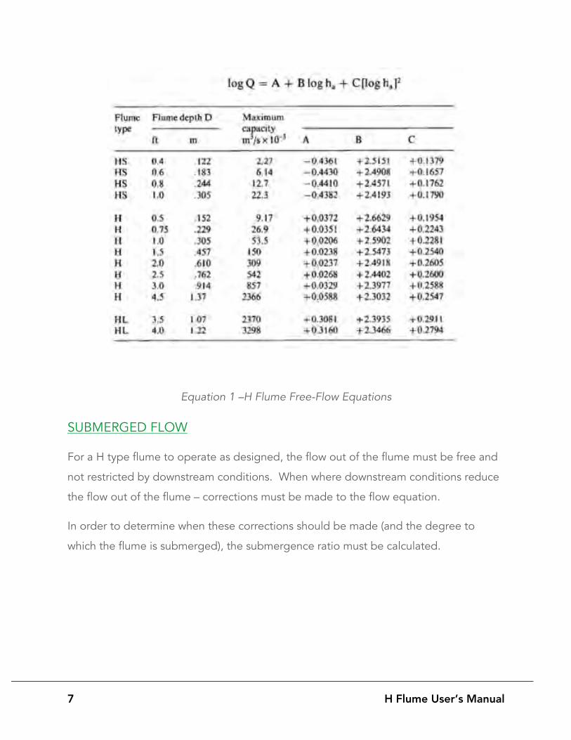
7 H Flume User’s Manual
Equation 1 –H Flume Free-Flow Equations
SUBMERGED FLOW
For a H type flume to operate as designed, the flow out of the flume must be free and
not restricted by downstream conditions. When where downstream conditions reduce
the flow out of the flume – corrections must be made to the flow equation.
In order to determine when these corrections should be made (and the degree to
which the flume is submerged), the submergence ratio must be calculated.
8 H Flume User’s Manual
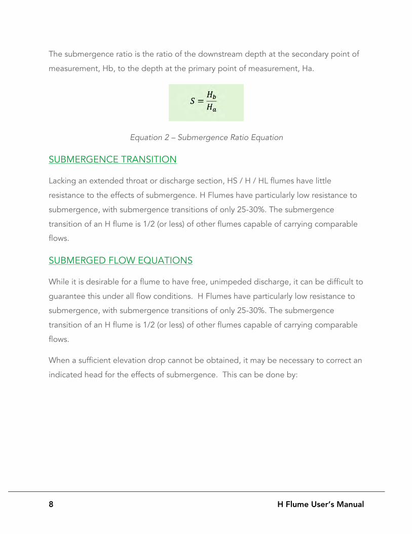
The submergence ratio is the ratio of the downstream depth at the secondary point of
measurement, Hb, to the depth at the primary point of measurement, Ha.
Equation 2 – Submergence Ratio Equation
SUBMERGENCE TRANSITION
Lacking an extended throat or discharge section, HS / H / HL flumes have little
resistance to the effects of submergence. H Flumes have particularly low resistance to
submergence, with submergence transitions of only 25-30%. The submergence
transition of an H flume is 1/2 (or less) of other flumes capable of carrying comparable
flows.
SUBMERGED FLOW EQUATIONS
While it is desirable for a flume to have free, unimpeded discharge, it can be difficult to
guarantee this under all flow conditions. H Flumes have particularly low resistance to
submergence, with submergence transitions of only 25-30%. The submergence
transition of an H flume is 1/2 (or less) of other flumes capable of carrying comparable
flows.
When a sufficient elevation drop cannot be obtained, it may be necessary to correct an
indicated head for the effects of submergence. This can be done by:
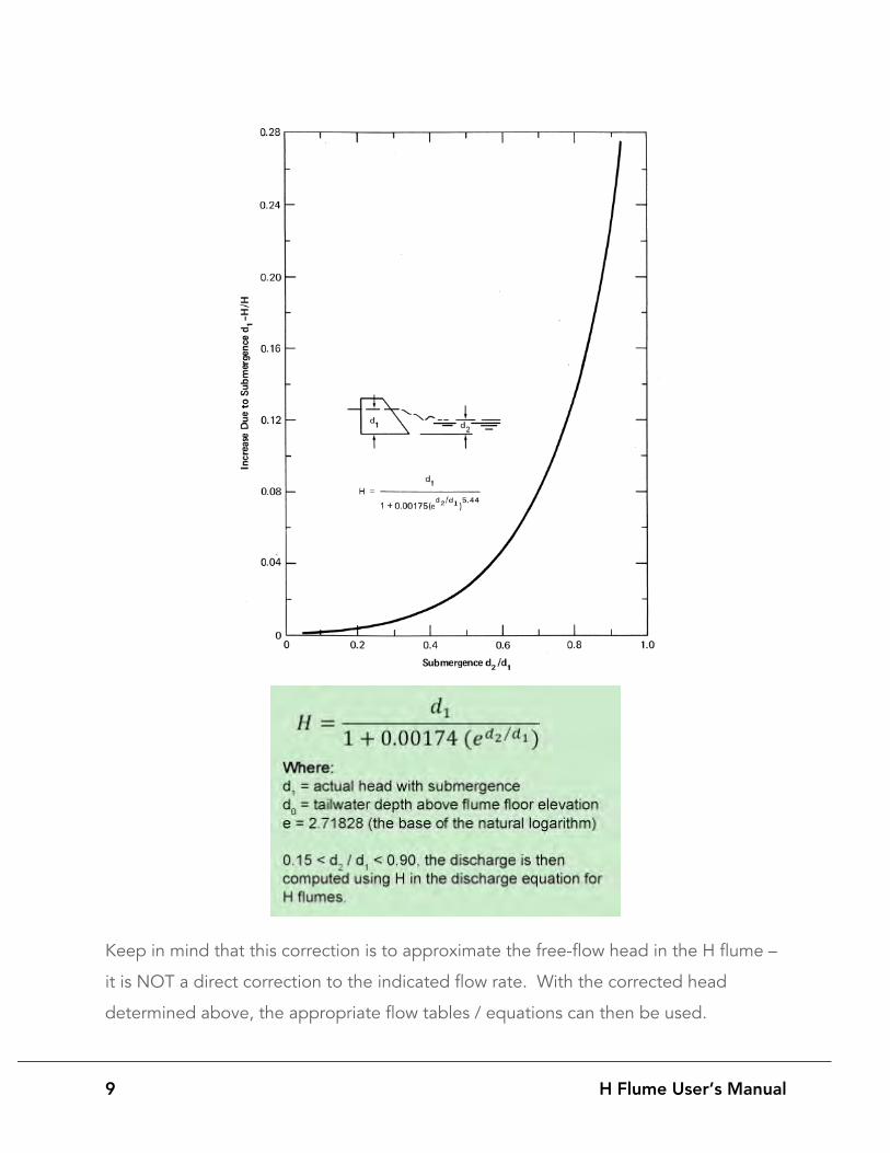
9 H Flume User’s Manual
Keep in mind that this correction is to approximate the free-flow head in the H flume –
it is NOT a direct correction to the indicated flow rate. With the corrected head
determined above, the appropriate flow tables / equations can then be used.
10 H Flume User’s
WHERE TO INSTALL A H FLUME
When selecting a site in which to install a H flume, there are several points to consider:
UPSTREAM OF THE FLUME
• Flow entering the flume MUST be sub-critical. • The Froude number (Fr) for flow entering a flume should not exceed 0.5 and
should never exceed 0.99. o Surface turbulence may be encountered for Froude numbers above 0.5. o For a flume to accurately measure flow, that flow must be sub-critical
(Fr<0.99). • If the approaching flow is critical (Fr = 1.0) or supercritical (Fr > 1.0), then a
hydraulic jump must be formed at least 30 times the maximum anticipated head (Hmax) upstream of the entrance to the flume or upstream energy absorbers must be used to slow the flow.
• The flow entering the flume should be smooth, tranquil, and well distributed across the channel.
• The approaching channel should be straight so that the velocity profile is uniform. Surging, turbulent, or unbalanced flows must be conditioned before the flow enters the flume.
• Any bends, dips, elbows, or flow junctions upstream of the flume must be sufficiently far upstream so that the flow has is well distributed and non-turbulent.
• The upstream channel should be straight for at least 3 to 5 times the maximum anticipated head (Hmax).
• H flumes have been successfully used in applications where the flow rises up a uniform vertical column and then enters the flume.
• Where the channel is wider than the inlet of the H flume, wing walls should be formed to smoothly direct the flow into the flume.
• When connecting to inlet piping, observations have shown that the pipe should be straight and without bends for at least 15 pipe diameters.
• The upstream channel should be clear of vegetative growth. • Open channel (non-full pipe) flow must be present under all flow conditions.

11 H Flume User’s
FLUME LOCATION
• The flume must be able to be set so that the floor is level from front-to-back and from side-to-side.
• When H flumes are installed in earthen channels and furrows, care should be taken to ensure that a stable bottom elevation is present and that the elevation does not change during dry / wet seasons or low-flow periods.
• The flume must be centered in the flow stream. • The narrow opening of the flume is set downstream. • All of the flow must go through the flume – there should be no bypass. • If sediment is a concern, the approach section can be provided with a sloped
floor (side-to-side) so that channelization does not occur. The slope should not exceed 1:8.
DOWNSTREAM OF THE FLUME
• Flow must freely spill off the end of a H flume. • The downstream channel should be armored (riprap) or otherwise protected so
that scour does not occur. • The downstream channel must be clear of vegetative growth or the collection of
debris so that flow does not back up into the flume.

12 H Flume User’s
HOW TO INSTALL A H FLUME
Once a site has been selected, the flume must then be installed correctly:
• The flume should be set so that it is centered in the flow stream. • The floor of the flume should be set high enough so that the flume does not
operate under submerged flow conditions. • The narrow opening of the flume must be set downstream. • The floor of the flume must be level from front-to-back and from side-to-side
(using a level on the floor - not the top - of the flume) • The flume must be braced internally (plywood and lumber are typically used)
during installation to ensure that distortion does not occur. • The flume must not float out of its intended final position during installation.
BRACING THE FLUME
Most H flumes ship with dimensional bracing (angle or tube) at the top of the flume.
The bracing should be left on the flume.

13 H Flume User’s
CONNECTION JOINTS
H flumes supplied with bulkheads or approach sections must remain sealed between
the joints.
While these joints may be sealed initially at the factory, a final visual inspection of all
joints should be done before installation. Where required, apply one or two
continuous beads of silicone on all seating surfaces before proceeding with the
installation.
HOW TO MAINTAIN A H FLUME
For a H flume to accurately measure flow, it must be periodically inspected and
maintained. This inspection should be done six (6) months after installation and each
following year.
The inspection should include the channel in which the flume is installed, the flow
entering / exiting the flume, and the flume itself.
CHANNEL INSPECTION
• The upstream channel banks should be clear of vegetation or debris that could affect the flow profile entering the flume (upstream) or restrict flow out of the flume (downstream).
• Inspect the upstream channel to make sure that flow is not bypassing the flume. • Inspect the downstream channel to make sure that scouring is not occurring. • Any hydraulic jump should be at least 30 times the maximum head (Hmax)
upstream of the flume.
14 H Flume User’s
FLOW INSPECTION
• Flow entering the flume should be tranquil and well distributed. • Turbulence, poor velocity profile, or surging should not be present. • The Froude (Fr) number should, ideally, be 0.5. • As the Froude number increases so does surface turbulence. • Flumes accelerate sub-critical flow (Fr < 1) to a supercritical state (Fr 1>) . • Flumes experiencing flows greater than unit (Fr = 1) will not accurately
measure flow.
FLUME INSPECTION
• Flumes must be level from front-to-back and from side-to-side. • Earthen installations are particularly susceptible to settling due to wet / dry
and freeze / thaw cycles. • Flow surfaces are to be kept clean of surface buildup or algal
growth. Scrubbing or a mild detergent can be used. • Galvanized flumes should be checked for corrosion. • Any corrosion should be removed and then cold galvanization applied to the
area.