H-Bridges and Electronic Motor Control...
17
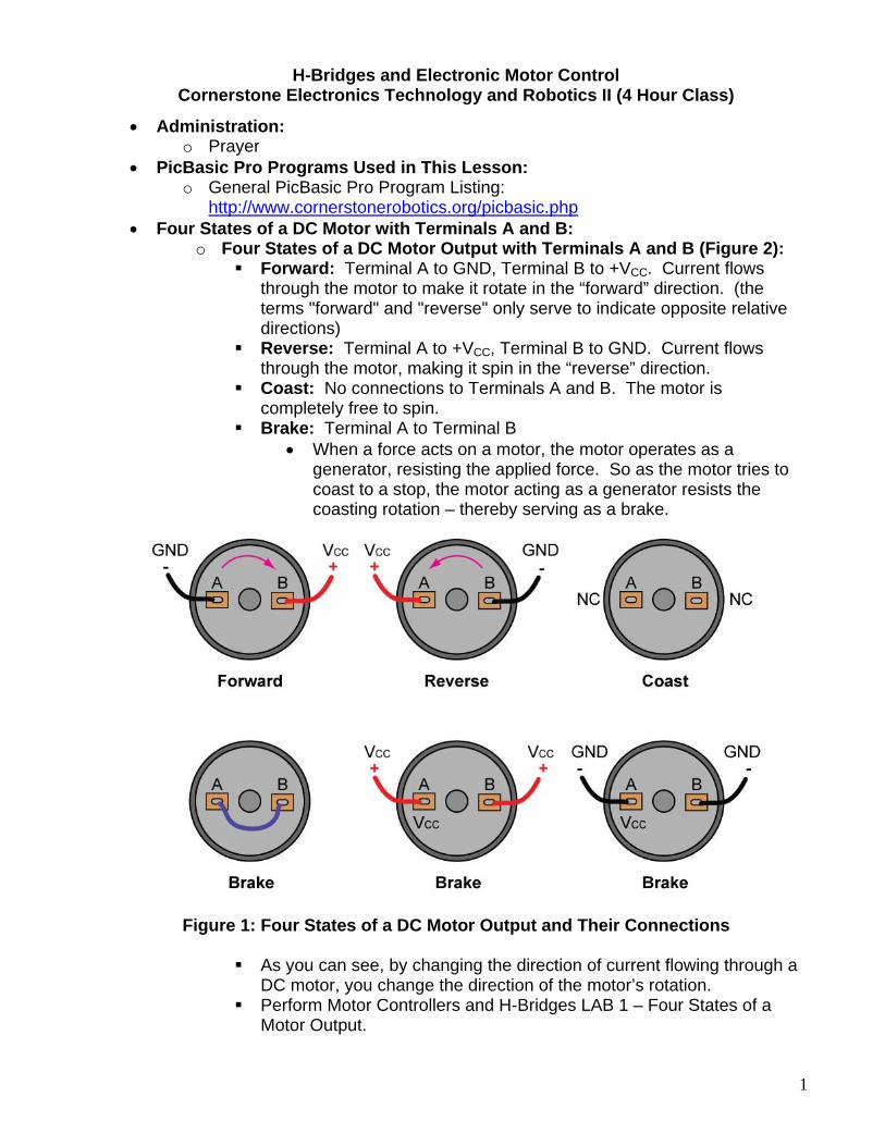
1 H-Bridges and Electronic Motor Control Cornerstone Electronics Technology and Robotics II (4 Hour Class) Administration: o Prayer PicBasic Pro Programs Used in This Lesson: o General PicBasic Pro Program Listing: http://www.cornerstonerobotics.org/picbasic.php Four States of a DC Motor with Terminals A and B: o Four States of a DC Motor Output with Terminals A and B (Figure 2): Forward: Terminal A to GND, Terminal B to +V CC . Current flows through the motor to make it rotate in the “forward” direction. (the terms "forward" and "reverse" only serve to indicate opposite relative directions) Reverse: Terminal A to +V CC , Terminal B to GND. Current flows through the motor, making it spin in the “reverse” direction. Coast: No connections to Terminals A and B. The motor is completely free to spin. Brake: Terminal A to Terminal B When a force acts on a motor, the motor operates as a generator, resisting the applied force. So as the motor tries to coast to a stop, the motor acting as a generator resists the coasting rotation – thereby serving as a brake. Figure 1: Four States of a DC Motor Output and Their Connections As you can see, by changing the direction of current flowing through a DC motor, you change the direction of the motor’s rotation. Perform Motor Controllers and H-Bridges LAB 1 – Four States of a Motor Output.
-
Upload
nguyenthuan -
Category
Documents
-
view
215 -
download
0
Transcript of H-Bridges and Electronic Motor Control...
1
H-Bridges and Electronic Motor Control Cornerstone Electronics Technology and Robotics II (4 Hour Class)
Administration: o Prayer
PicBasic Pro Programs Used in This Lesson: o General PicBasic Pro Program Listing:
http://www.cornerstonerobotics.org/picbasic.php Four States of a DC Motor with Terminals A and B:
o Four States of a DC Motor Output with Terminals A and B (Figure 2): Forward: Terminal A to GND, Terminal B to +VCC. Current flows
through the motor to make it rotate in the “forward” direction. (the terms "forward" and "reverse" only serve to indicate opposite relative directions)
Reverse: Terminal A to +VCC, Terminal B to GND. Current flows through the motor, making it spin in the “reverse” direction.
Coast: No connections to Terminals A and B. The motor is completely free to spin.
Brake: Terminal A to Terminal B When a force acts on a motor, the motor operates as a
generator, resisting the applied force. So as the motor tries to coast to a stop, the motor acting as a generator resists the coasting rotation – thereby serving as a brake.
Figure 1: Four States of a DC Motor Output and Their Connections
As you can see, by changing the direction of current flowing through a DC motor, you change the direction of the motor’s rotation.
Perform Motor Controllers and H-Bridges LAB 1 – Four States of a Motor Output.

2
The Need for Motor Drivers: o Motor drivers provide high currents to a motor. o Motor drivers provide higher voltages to motors than microcontrollers can
handle. o Motor drivers isolate logic circuits from motor spikes and electrical noise from
the motor. o Motor drivers supply unregulated power from batteries.
Basic H-Bridges Motor Driver Circuit: o The H-Bridge motor driver circuit is known as an H-Bridge because it
resembles the capital letter “H”. o H-Bridge using SPST switches:
The motor in the following circuit will operate only when the diagonally opposite switches are closed.
Figure 2: Motor Runs “Forward” Figure 3: Motor Runs in “Reverse” (Switches 1 and 4 Closed) (Switches 2 and 3 Closed)
o What happens if S1 and S2 or S3 and S4 are closed simultaneously? o Perform Motor Control, H-Bridges LAB 2 – H-Bridges with SPST Switches
3
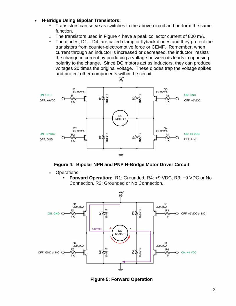
H-Bridge Using Bipolar Transistors: o Transistors can serve as switches in the above circuit and perform the same
function. o The transistors used in Figure 4 have a peak collector current of 800 mA. o The diodes, D1 – D4, are called clamp or flyback diodes and they protect the
transistors from counter-electromotive force or CEMF. Remember, when current through an inductor is increased or decreased, the inductor "resists" the change in current by producing a voltage between its leads in opposing polarity to the change. Since DC motors act as inductors, they can produce voltages 20 times the original voltage. These diodes trap the voltage spikes and protect other components within the circuit.
Figure 4: Bipolar NPN and PNP H-Bridge Motor Driver Circuit
o Operations: Forward Operation: R1: Grounded, R4: +9 VDC, R3: +9 VDC or No
Connection, R2: Grounded or No Connection,
Figure 5: Forward Operation

4
Reverse Operation: R3: Grounded, R2: +9 VDC, R1: +9 VDC or No
Connection, R4: Grounded or No Connection
Figure 6: Reverse Operation
Braking: R1 and R3: Grounded with R2 and R4: Grounded or No Connection
Figure 7: Braking
5
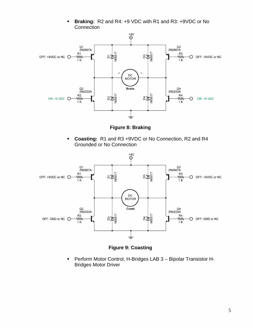
Braking: R2 and R4: +9 VDC with R1 and R3: +9VDC or No Connection
Figure 8: Braking
Coasting: R1 and R3 +9VDC or No Connection, R2 and R4 Grounded or No Connection
Figure 9: Coasting
Perform Motor Control, H-Bridges LAB 3 – Bipolar Transistor H-Bridges Motor Driver
6
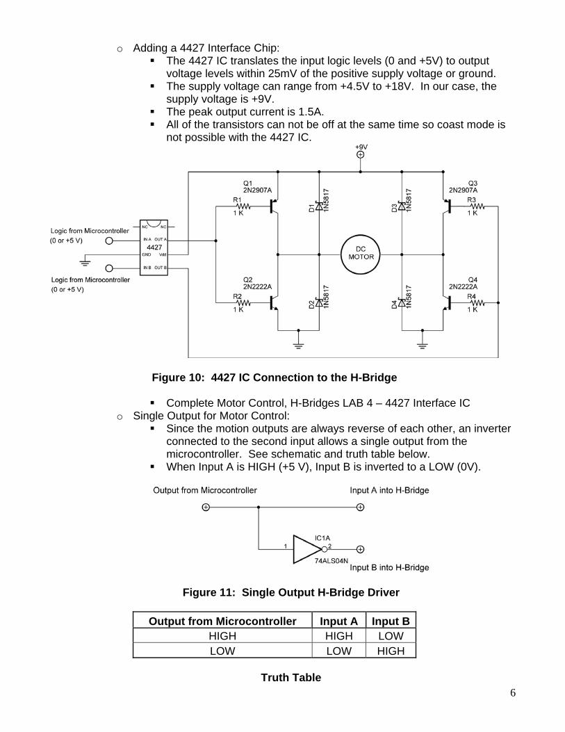
o Adding a 4427 Interface Chip: The 4427 IC translates the input logic levels (0 and +5V) to output
voltage levels within 25mV of the positive supply voltage or ground. The supply voltage can range from +4.5V to +18V. In our case, the
supply voltage is +9V. The peak output current is 1.5A. All of the transistors can not be off at the same time so coast mode is
not possible with the 4427 IC.
Figure 10: 4427 IC Connection to the H-Bridge
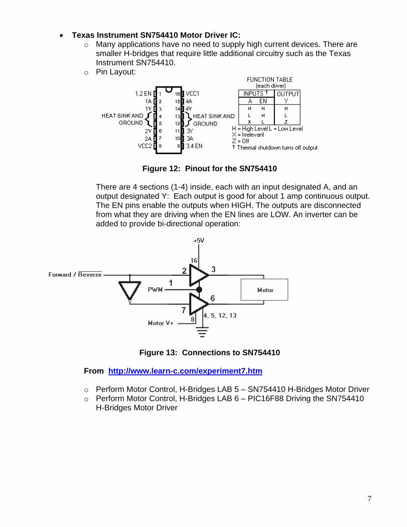
Complete Motor Control, H-Bridges LAB 4 – 4427 Interface IC o Single Output for Motor Control:
Since the motion outputs are always reverse of each other, an inverter connected to the second input allows a single output from the microcontroller. See schematic and truth table below.
When Input A is HIGH (+5 V), Input B is inverted to a LOW (0V).
Figure 11: Single Output H-Bridge Driver
Output from Microcontroller Input A Input B HIGH HIGH LOW LOW LOW HIGH
Truth Table
7
Texas Instrument SN754410 Motor Driver IC: o Many applications have no need to supply high current devices. There are
smaller H-bridges that require little additional circuitry such as the Texas Instrument SN754410.
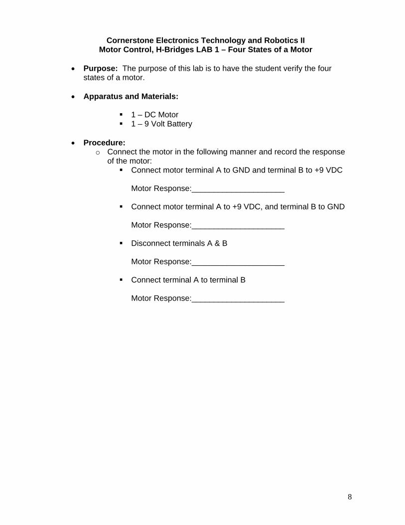
o Pin Layout:
Figure 12: Pinout for the SN754410
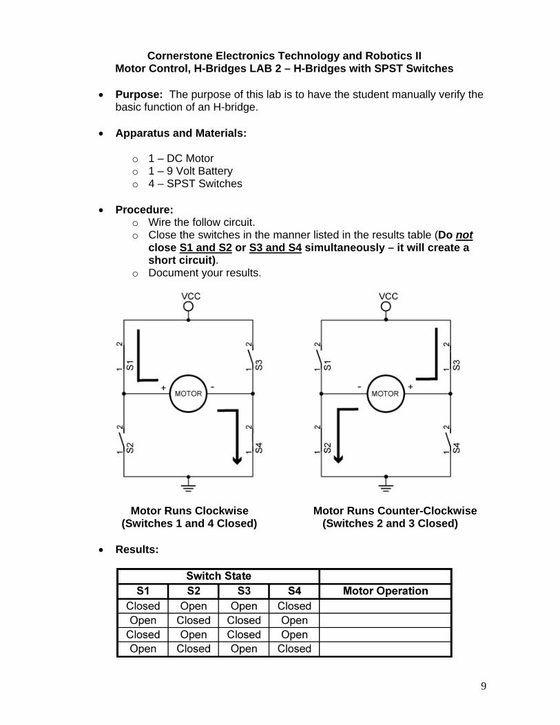
There are 4 sections (1-4) inside, each with an input designated A, and an output designated Y: Each output is good for about 1 amp continuous output. The EN pins enable the outputs when HIGH. The outputs are disconnected from what they are driving when the EN lines are LOW. An inverter can be added to provide bi-directional operation:
Figure 13: Connections to SN754410
From http://www.learn-c.com/experiment7.htm
o Perform Motor Control, H-Bridges LAB 5 – SN754410 H-Bridges Motor Driver o Perform Motor Control, H-Bridges LAB 6 – PIC16F88 Driving the SN754410
H-Bridges Motor Driver
8
Cornerstone Electronics Technology and Robotics II Motor Control, H-Bridges LAB 1 – Four States of a Motor
Purpose: The purpose of this lab is to have the student verify the four
states of a motor.
Apparatus and Materials:
1 – DC Motor 1 – 9 Volt Battery
Procedure: o Connect the motor in the following manner and record the response
of the motor: Connect motor terminal A to GND and terminal B to +9 VDC
Motor Response:_____________________
Connect motor terminal A to +9 VDC, and terminal B to GND
Motor Response:_____________________
Disconnect terminals A & B
Motor Response:_____________________
Connect terminal A to terminal B
Motor Response:_____________________
9
Cornerstone Electronics Technology and Robotics II Motor Control, H-Bridges LAB 2 – H-Bridges with SPST Switches
Purpose: The purpose of this lab is to have the student manually verify the
basic function of an H-bridge.
Apparatus and Materials:
o 1 – DC Motor o 1 – 9 Volt Battery o 4 – SPST Switches
Procedure:
o Wire the follow circuit. o Close the switches in the manner listed in the results table (Do not
close S1 and S2 or S3 and S4 simultaneously – it will create a short circuit).
o Document your results.
Motor Runs Clockwise Motor Runs Counter-Clockwise (Switches 1 and 4 Closed) (Switches 2 and 3 Closed)
Results:

10
Cornerstone Electronics Technology and Robotics II Motor Control, H-Bridges LAB 3 – Bipolar Transistor H-Bridges Motor Driver
Purpose: The purpose of this lab is to have the student setup an electronic
H-bridge and to operate it manually.
Apparatus and Materials:
o 1 – DC Motor o 1 – 9 Volt Battery o 2 – 2N2907A PNP Transistors o 2 – 2N2222A NPN Transistors o 4 – 1N5817 Diodes
Procedure:
o As with switches, do not short circuit through the transistors (Q1 & Q2 or Q3 & Q4).
o Wire the following circuit the robotic car breadboard. o Connect the inputs to the transistor bases according to the following
table and record the action of the motor:
Transistor Connections
Q1 Q2 Q3 Q4 Motor Operation +9V +9V GND GND GND GND +9V +9V GND Disconnected GND Disconnected
Disconnected +9V Disconnected +9V Disconnected Disconnected Disconnected Disconnected
CHECK LINES 3 & 4 FOR +9 AND GND RESPECTIVELY
Tie the inputs of Q1 and Q2 together and also connect the inputs of Q3 and Q4 together. What purpose do these connections serve?

11
Cornerstone Electronics Technology and Robotics II Motor Control, H-Bridges LAB 4 – 4427 Interface IC
Purpose: The purpose of this lab is to have the student insert a 4427
interface IC to simplify the control of an H-bridge. Apparatus and Materials:
o 2 – DC Motors o 1 – 4427 Interface IC o 2 – 2N2907A PNP Transistors o 2 – 2N2222A NPN Transistors o 4 – 1N5817 Diodes
Procedure:
o Refer to the 4427 Interface IC H-Bridge Output Results Table below. Given the inputs for A and B, fill in the states of Q1-Q4 (On or off), then predict the action of the motor (Clockwise, counter-clockwise, braking, or coasting).
o Now wire the 4427 interface IC circuit below. o Apply a HIGH, Low, or Disconnect to the inputs A and B of the 4427
IC. o Record the experimental results in the table.
4427 Interface IC Circuit Results:
4427 Interface IC H-Bridge Output Results
Input A Input B Q1 Q2 Q3 Q4 Predicted Results Experimental Results HIGH HIGH HIGH LOW LOW HIGH LOW LOW

12
Cornerstone Electronics Technology and Robotics II Motor Control, H-Bridges LAB 5 – SN754410 H-Bridges Motor Driver
Purpose: The purpose of this lab is to acquaint the student with the operation of a single chip motor driver – SN754410 by Texas Instrument.
Discussion:
o PWM has yet to be covered so the PWM ports are either set HIGH (100% duty cycle) or LOW (0% duty cycle) See the lesson on PWM to adjust values between 100% and 0%.
Apparatus and Materials:
o 2 – Gearhead DC Motors, Jameco #155855 o 1 – SN754410 Quadruple Half-H Driver, Pololu #0024 o 1 – 74LS04 Hex-Inverter o 8 – 1N5817 Diodes o 4 – 10K Resistors o 1 – 1000 uF Capacitor
Procedure:
o Wire the circuit below and make the input connections as follows: Motor + Voltage to +9V PWM Motor 1 and 2 to 0V or +5V Forward/Reverse Motor 1 and 2 to 0V or +5V Complete the table below.
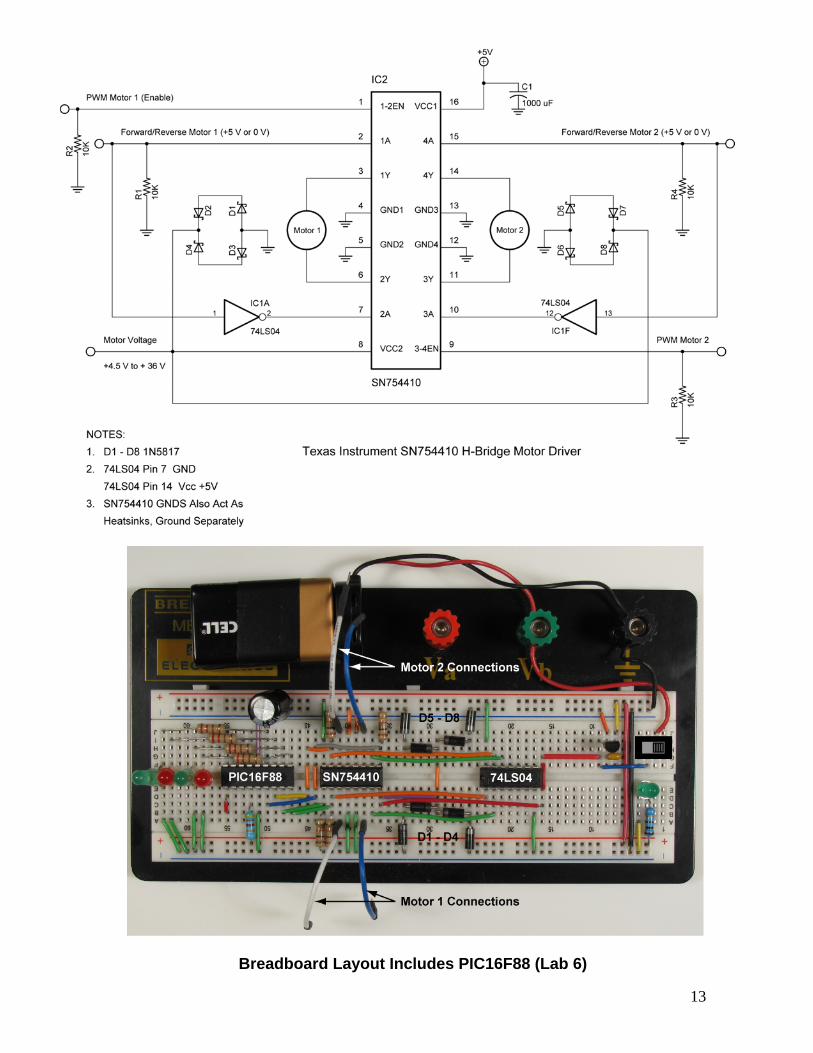
13
Breadboard Layout Includes PIC16F88 (Lab 6)
14
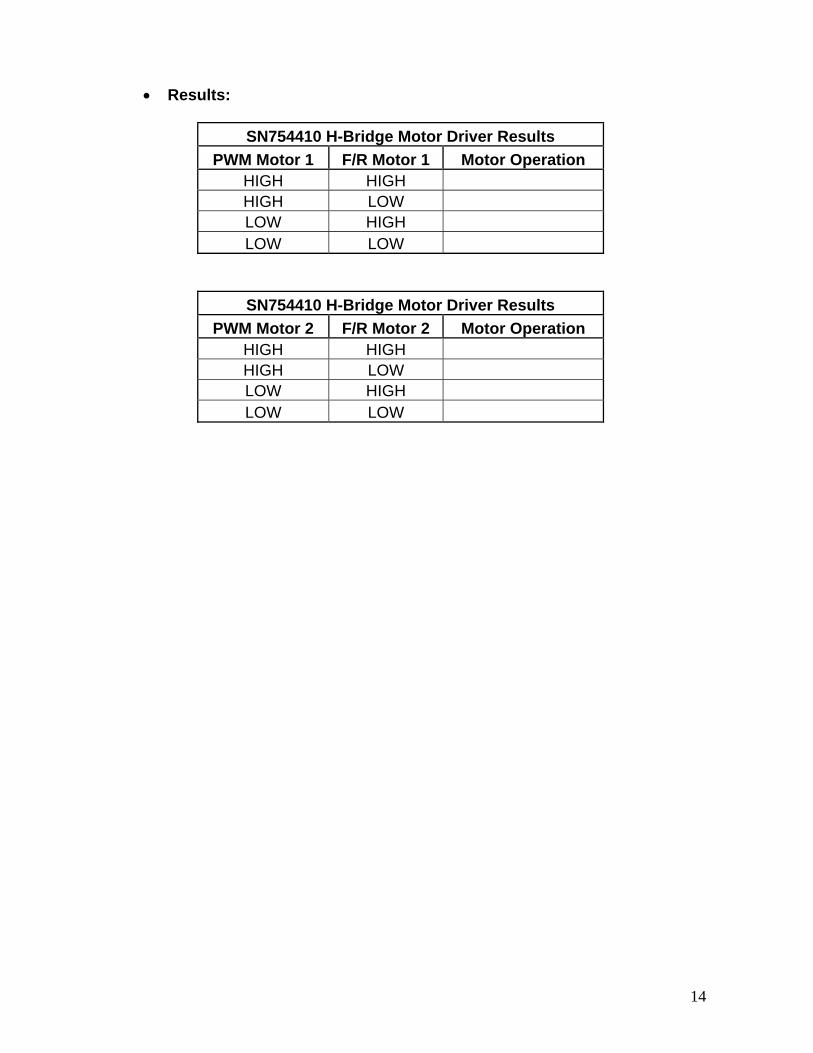
Results:
SN754410 H-Bridge Motor Driver Results
PWM Motor 1 F/R Motor 1 Motor Operation HIGH HIGH HIGH LOW LOW HIGH LOW LOW
SN754410 H-Bridge Motor Driver Results
PWM Motor 2 F/R Motor 2 Motor Operation HIGH HIGH HIGH LOW LOW HIGH LOW LOW

15
Cornerstone Electronics Technology and Robotics II Motor Control, H-Bridges LAB 6 – PIC16F88 Driving the SN754410 H-Bridges
Motor Driver
Purpose: The purpose of this lab is to acquaint the student with using a PIC microcontroller to drive a single chip motor driver – SN754410 by Texas Instrument.
Apparatus and Materials:
o 1 – Robotic Car Platform o 2 – Gearhead DC Motors, Jameco #155855 o 1 – SN754410 Quadruple Half-H Driver, Pololu #0024 o 1 – 74LS04 Hex-Inverter o 1 – PIC16F88 o 8 – 1N5817 Diodes o 1 – 4.7K Resistor o 4 – 10K Resistors o 2 – 150 Ohm Resistors o 2 – LEDs o 1 – 1000 uF Capacitor
Procedure:
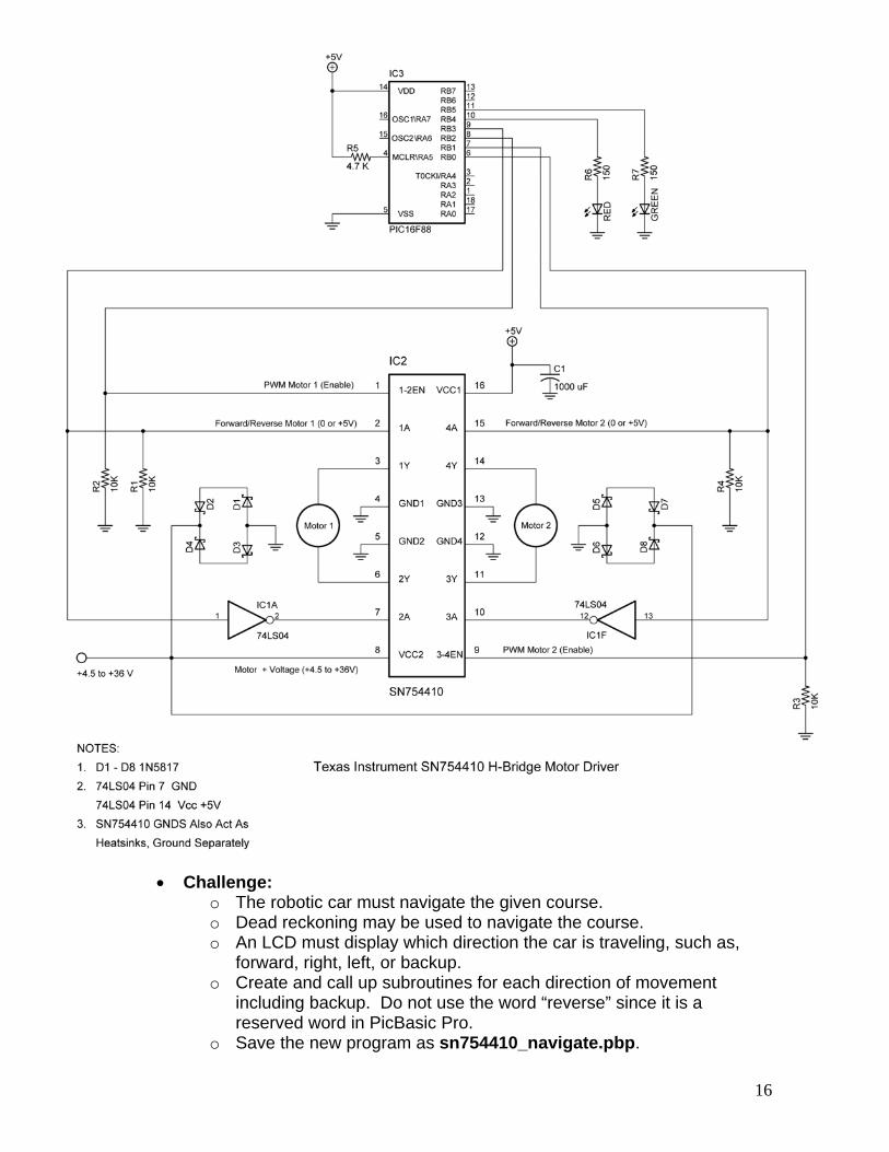
o Wire the following circuit on the robotic car breadboard. See the photo in Lab 5 for one possible layout.
o Make sure that the motor is from a power supply separate from the PIC16F88.
o Program the PIC16F88 with h_bridge_sn754410_1.pbp.
16
Challenge: o The robotic car must navigate the given course. o Dead reckoning may be used to navigate the course. o An LCD must display which direction the car is traveling, such as,
forward, right, left, or backup. o Create and call up subroutines for each direction of movement
including backup. Do not use the word “reverse” since it is a reserved word in PicBasic Pro.
o Save the new program as sn754410_navigate.pbp.

17
Motor Control, H-Bridges LAB 2 – H-Bridges with SPST Switches
Results to Motor Control, H-Bridges LAB 4 – 4427 Interface Chip
4427 Interface IC H-Bridge Output Results
Input A Input B Q1 Q2 Q3 Q4 Predicted Results Experimental Results HIGH HIGH Off On Off On Braking Braking HIGH LOW Off On On Off Clockwise Clockwise LOW HIGH On Off Off On Counterclockwise Counterclockwise LOW LOW On Off On Off Braking Braking