Gyro With Avr
101
Design and implementation of an IMU device for robotics and multimedia Master Thesis in Telecommunications Engineering Mälardalen University School of Innovation, Design and Engineering October 2010 Author, David Espina Supervisor, Lars Asplund
-
Upload
yash-sharma -
Category
Documents
-
view
252 -
download
0
Transcript of Gyro With Avr

7/22/2019 Gyro With Avr
http://slidepdf.com/reader/full/gyro-with-avr 1/101
Design and implementation ofan IMU device for robotics
and multimedia
Master Thesis in Telecommunications EngineeringMälardalen University
School of Innovation, Design and EngineeringOctober 2010
Author, David Espina
Supervisor, Lars Asplund

7/22/2019 Gyro With Avr
http://slidepdf.com/reader/full/gyro-with-avr 2/101

7/22/2019 Gyro With Avr
http://slidepdf.com/reader/full/gyro-with-avr 3/101
Table of contents..................................................................................................1
1.Abstract..................................................................................................................................................2
2.Preface...................................................................................................................................................4
3.Introduction............................................................................................................................................6
3.1.Research and data gathering...............................................................................................................6
3.2.The Vision...........................................................................................................................................9
4.Development........................................................................................................................................12
4.1.Merge of technologies.......................................................................................................................12
4.1.1.Circuit board performance.............................................................................................................14
4.1.2.Components...................................................................................................................................18
4.1.3.Communications............................................................................................................................39
4.2.Hardware...........................................................................................................................................47
4.2.1.Hardware design............................................................................................................................48
4.2.2.Hardware construction...................................................................................................................60
4.3.Software............................................................................................................................................62
4.3.1.Tools and environment...................................................................................................................62
4.3.2.MCU programmer..........................................................................................................................71
4.3.3.JTAG JTAGPortTest.c...................................................................................................................72
4.3.4.AVR Project iMYou.......................................................................................................................73
4.3.5.Compatibility with iNemo.............................................................................................................74
4.3.6.Applications...................................................................................................................................75
5.Conclusions..........................................................................................................................................76
6.Future Work.........................................................................................................................................76
7.References............................................................................................................................................80
Appendix A: JTAG Test code.................................................................................................................83
Appendix B: AVR iMYou Project...........................................................................................................85
David Espina - Master Thesis in Telecommunications Engineering - 2010
Page 1

7/22/2019 Gyro With Avr
http://slidepdf.com/reader/full/gyro-with-avr 4/101
1.Abstract
Inertial motion units (IMUs) where conceived as a support element for precision in military navigation
systems; now it’s projected to use it to entertain and create music.This paper is a compendium that covers all the stages of the development of the inertial motion unit
built as a master thesis research work by David Espina supervised at Mälardalen University and valid
for his home institution, Universidad Pública de Navarra, as a part of an exchange program. The
development of the project is dated on January 2010 and the ending of the research is october 2010.
The objective of this project was to design and implement an IMU unit using as many resources as
possible from other projects going on at MDH. In this manner, the development process would get first
hand documentation from the master and PhD students who worked on the listed technologies: PCB
design, ATmega micro controllers, USB-Serial communications, Bluetooth ® stack, Honeywell
magnetometer, ST Electronics gyroscopes and accelerometer. The project was planned from start
analyzing the different stages of the work: data gathering, schematic, layout, manufacturing, mounting,testing, code writing and programming. Before the beginning of the project there has been a learning
process of different programming platforms and environment such as ADA, AVR Studio and Cocoa
for iPhone applications. After the research was over this paper began to be written.
The paper covers the work done from the idea to the first finished version of the firmware of the
prototype.
The writing has been structured following the strict development process with a previous general
description of every part that conforms the system, which will be referred as iMYou attending as a
nickname for the IMU device built. The preface is numbered as part number two. This second part
tries to answers questions such as why? and when?, related to the subject of the project and the origin
of the idea.The third part of the paper is an introduction which covers aspects about previous work performed by
other students, different institutions and different companies. It shows that the iMYou device is not
100% an innovative device, but an interesting approach to bring engineering into multimedia and
business.
The fourth part explains in detail the development process, starting with a description of the
technologies used, followed by an explanation of the whole system and detailed description of every
submodule and component, both hardware and software. This part covers the methodology followed,
the decisions taken, problems that emerged from those decisions and also the strategy adopted to broad
those problems. There are figures and tables the complete the explanations in a graphic and structured
way.
Part five is a conclusion after analyzing those results taken after the research, built and programming
were done. To be noticed that this was a project aiming to keep a low price of non-recurrent
engineering (NRE) since there was a market idea behind.
The sixth part is a guide for those who want to continue with the development and upgrading of the
iMYou system. This way anyone with the proper background can easily understand the purposes and
David Espina - Master Thesis in Telecommunications Engineering - 2010
Page 2

7/22/2019 Gyro With Avr
http://slidepdf.com/reader/full/gyro-with-avr 5/101
protocols not to waste time reading and understanding from the beginning and get to work straight
away with a clear picture of what they have to do.
In the ninth part there are some personal thoughts of how to continue working on the iMYou device
and future developers have suggestions of what there could be changed of improved.The seventh part is a list of sources and references.
The are two last parts called Appendix A and Appendix B where the source code can be found.
Keywords: inertial motion unit, RS232, hyper terminal, USB, Bluetooth, gyroscope, accelerometer,
compass, SMD, CAD, baud rate, UART, TWI, ISP, ADC, I2C, SPI, ADA programming, AVR Studio,
Ultiboard, Multisim, Eagle, C/C#, Objective C.
David Espina - Master Thesis in Telecommunications Engineering - 2010
Page 3

7/22/2019 Gyro With Avr
http://slidepdf.com/reader/full/gyro-with-avr 6/101
2.Preface
This paper has been written to describe the process of designing, building and programming an IMU
from the idea to the prototype.The idea was born in september 2008 at the campus of the Universidad Pública de Navarra (UPNA) in
a morning break, while students of last year of Telecommunications Engineering brainstormed about
their future careers combining music and engineering. That morning me, Javier Barbadillo Amor and
Yeray Alfageme Ramirez studied the possibility of creating a system to interact with musicians while
they performing on a live scene to manipulate the signals from their instruments according to their
body movements, muscle tension, blood pressure and other ideas such as level of adrenaline
segregated at a particular moment of the performance. During that conversation we had on our hands
the latest volume of a technology magazine delivered in the university and there was an article about
the Hot Hand ® Wah unit, a ring shape device built to process movements of a guitar player’s hand
[1]. That technology was fascinating and I wanted to know more about it. Fortunately at MälardalenUniversity (MDH) in Sweden, Lars Asplund; professor of robotics and tutor for both bachelor and
master thesis in electronics and robotics, was interested on a student to build an IMU device to control
a keyboard both for typewriting and making music.
The idea presented was a big project to perform by one student of masters of engineering during
maximum 9 months including the writing of the paper and the official presentation at the UPNA,
which would had fit better for a team of four or five people. The multiple and different stages
proposed started with the designing and production of a circuit board with a commercial design and
size to be placed in a structure portable on the external side of the hand. Second stage was
programming of the board and set the communication with the PC or MAC. Fourth stage was writing
an application to use the data from the IMU device and manipulate an audio sequencer or asynthesizer. The last planned stage was the development of an iphone application to monitor the
performance of the IMU and the PC/MAC for the user to be able to perform and control the device
with multiple options.
The final output was envisioned as a commercial product for musicians and as a leisure element. As it
is explained in the paper, the applications are multiple, an due to the magnitude of the project, there
one most urgent one would be controlling a robot arm, since there are multiple projects in this field run
by several student at MDH.
It’s been a very complex process since every stage presents several problems to deal with that delayed
the development of the other parts. In fact the process is incomplete and the status is stage 1 complete,
stage 2 incomplete, stage 3 empty and beginning of stage 4.
This report will give a details of every decision taken during the process, the different techniques used
for the diverse tools and technologies used, a description of the found problems and the strategies to
solve and overcome them.
David Espina - Master Thesis in Telecommunications Engineering - 2010
Page 4

7/22/2019 Gyro With Avr
http://slidepdf.com/reader/full/gyro-with-avr 7/101
There is a section by the end of this paper called User and programmer manual that explains how to
proceed in case that anyone would like to test the device of in case that someone takes this project and
continues the implementation of it or adds new features.
The last section is Future work which gives a vision of what should be done next about this projectand other related projects.
Very Special thanks to: Lars Asplund, Fredrik Ekstrand, Giacomo Spampinato, Martin Ekström,
Rikard Lindel, Mikael Ekström and Carl Ahlberg for all the good advices, contacts, help and patience.
David Espina - Master Thesis in Telecommunications Engineering - 2010
Page 5

7/22/2019 Gyro With Avr
http://slidepdf.com/reader/full/gyro-with-avr 8/101
3.Introduction3.1.Research and data gathering
An Inertial Measurement Unit (IMU) has solved problems of navigation since the 70’s in aircrafts and
war machinery such as guided missiles and has evolved to combine technology and ludic activities.
Paul L. DiMatteo presented in New York in 1976 a patent registered with the name Navigational error
correcting system in which described a system based on a radar that would communicate with aircrafts
to calculate their position and correct flight trajectories [1]. Works like this or the one performed by
Auerbach later the same year, started to solve a technological necessity in aviation [2]. However,
these where known techniques taken from navigation to aerospace science, and didn’t include a mayor
technological advance. In 1980, Theodore Mairson set the basis of the modern concept of IMU
including a processor that would compute angular velocity and translational acceleration in terms of
dynamic variables [3]. The processor is able to do multiple calculus from the outputs of the
transducers and, in terms of linear combinations, define de motion of the inertial measurement. Four
years later another evolutionary step was made by adding a new feature to the concept of inertial
measurement for navigation by including earth-pointing acquisition [4]. With this upgrade IMUs had
the possibility to combine the position and the angular subtense of the earth, providing an earth-
pointed equilibrium state. The basic components are set in three categories: rotational components or
gyroscopes (gyros), translational components or accelerometers and earth-pointing components or
compass. To establish a standardized measurement method Jeffrey T. Smith released Inertial Reference
System in 1984 where established the format of the output for this components. They all produce a set
of pulses that refer in each case to the rate of angular deviation for the gyros, the rate of velocity
deviation for the accelerometers and the rate of angular deviation from the magnetic field reference for
the compass [5]. The resultant counts are stored in registers for periodic sampling by the processor P1
that compensates possible measurement errors due to the time of the different samples, temperature,
bias offset, scale factors, etc. Then the data is transferred to the processor P2 which performs
navigational computations to produce computed positional information. The latest added features to
the definition of the IMUs increase the accuracy of the measurements, for instance the aid of an extra
gyro to compensate the rotation included by platforms and bodies under some sort of rotational
movement where the IMU is placed [6]. Most recently new algorithms and filters have been added
such as Low dynamic IMU alignment in which results suggest that alignment and aided navigation can
be accomplished and sustained with a navigation filter algorithm which implements the perturbation
error model without an alignment maneuver [7].
The processors are computational elements the rule the core of the performance of the IMU. They are
a sort of embedded systems that include in one single processing unit full development tools to control
hardware components such as sensors and compute data by embedded software to communicate with
other systems [8]. The hardware can be composed of sensors, actuators, memory storage,
communication peripherals and power supplies. The software includes an operating system, device
drivers, and an specific algorithm to control the system’s behavior. There are IMUs that use a specific
David Espina - Master Thesis in Telecommunications Engineering - 2010
Page 6
7/22/2019 Gyro With Avr
http://slidepdf.com/reader/full/gyro-with-avr 9/101
embedded system that use embedded Internet communication protocols, called Embedded Internet
Systems (EIS), and their particular feature is the possibility of transmitting data directly to the Internet
without specialized gateways [9]. The particular usage for an IMU system with the characteristics that
will be described in this paper requires a wireless connexion in an environment of what is calledPersonal Area Network (PAN) [10]. PAN devices use standard protocols such as Wi-fi and Bluetooth,
general purpose technologies and are aimed for audio and video streaming, web browsing, and file
transfer. Different from the use of Wireless Sensor Networks (WSN), which number of IMU devices is
not limited and usually up to several thousands, and PAN nowadays is the consumer focus of these last
ones, compared to scientific, military and industrial purposes of the WSN. Key factors for PAN
devices for commercialization are power consumption, interoperability with other consumer devices
and combination of WNS and PAN devices.
In this paper is presented the work of this building an IMU device operating in a PAN and defining its
own protocols as well as combining with known consumer devices which have implemented their own
protocols adapted to standards. The performance of this device is aimed for a low power consumptionand a low level of complexity of embedded calculus. Using Bluetooth as the communication tool from
the device to the processing machine or server enables interoperability with existing infrastructures,
mobility and real-time monitoring. The building of this IMU device coded with the nickname of
iMYou, was a matter of being able to build an own customized product to be able to modify it at will
and commercialized and there are several devices out in the market: ONI-23505 [11] (figure 3.1.1),
STEVAL-MKI062V1 [12] (figure 3.1.2), which are an IMU device with serial communication;
BTNode [13] (figure 3.1.3), iMote [14], Mulle [15] (figure 3.1.4), which are Bluetooth based network
devices without sensors; and an example of what iMYou is designed for is BT-IMU [16] (figure 3.1.5)
or the 6DOF [17] (figure 3.1.6), which combines IMU sensors and Bluetooth communications.
figure 3.1.1. ONI-23505
David Espina - Master Thesis in Telecommunications Engineering - 2010
Page 7

7/22/2019 Gyro With Avr
http://slidepdf.com/reader/full/gyro-with-avr 10/101
figure 3.1.2. STEVAL-MKI062V1
figure 3.1.3. BTNode
David Espina - Master Thesis in Telecommunications Engineering - 2010
Page 8

7/22/2019 Gyro With Avr
http://slidepdf.com/reader/full/gyro-with-avr 11/101
figure 3.1.4. Mulle
figure 3.1.5. BT-IMU
figure 3.1.6. 6DOF
3.2The Vision
The iMYou device was conceived as an interface to control music on-the-go. The user would interact
with the music that is playing in a device such as a laptop, mp3 player or a PA in a live show. Hewlett-
Packard released in 2004 the DJammer with the same philosophy, oriented to Club music [18]. This
David Espina - Master Thesis in Telecommunications Engineering - 2010
Page 9

7/22/2019 Gyro With Avr
http://slidepdf.com/reader/full/gyro-with-avr 12/101
device is built with inertial motion components communicates via bluetooth with the host controller
(PC/MAC) and provides different levels of interaction with the music played such as modifying FX
(tremolo, choruses, echo, delay, etc), volumes and panoramas or adding scratching sounds (figure
3.2.1).
figure 3.2.1. DJammerThe same way HP did in 2005 by adding an external device to monitor DJammer actions, an added
feature for the iMYou was envisioned to improve its future performance. This feature was an iPhone
app that would monitor the PC/Mac host application and would be able to control some parameters.
The final vision of the iMYou system before starting development is shown in figure 3.2.2.
David Espina - Master Thesis in Telecommunications Engineering - 2010
Page 10

7/22/2019 Gyro With Avr
http://slidepdf.com/reader/full/gyro-with-avr 13/101
figure 3.2.2. iMYou System
David Espina - Master Thesis in Telecommunications Engineering - 2010
Page 11

7/22/2019 Gyro With Avr
http://slidepdf.com/reader/full/gyro-with-avr 14/101
4.Development.
In this part there is an in-depth description of the development process from the analysis of the
technology used to the programming of the embedded systems and the software applications.This IMU device is a compendium of different embedded systems which communicate with one
another with standard protocols. These components have specific electrical characteristics and voltage
requirements which can be found in the data sheet of the manufacturer. Every pin of each component
behaves differently when there is a current through them and some require the presence of other
passive components near such as capacitors and resistors to filter noise and avoid peak,s or diodes to
limit voltage.
Embedded systems, despite of existing many different purposes, materials, physical conditions and
capabilities, they all have a similar structure and they can be programmed with specific tools to
communicate. Most of the components have a memory register where is hold vital information for
their performance. Some of them can have their own application programming interface (API)implemented so the programmer can easily write code on standard platforms. Most common
information hold in the only readable memory of those components are commands and instructions for
notification of state changes, notification of requests from I/O pins, incoming package of information,
acknowledgement of information sent.
The most important component is the micro controller (MCU) which provides communication
between components, data gathering from I/O pins, processor unit to perform calculus and redistribute
the data, memory registers to acquire data and results, built-in instructions to easily manage power
consumption and clock frequency. Each family of micro controllers has its own programming
environment which translates programming languages such as C/C++/C# into an hex file,
understandable for the physical layers of the MCU.
4.1.Merge of technologies.
The election of components of the iMYou has beed done considering the technology available for a
low cost of production, compatibility with other projects performed at MDH before and a commercial
purpose as a goal. This last point has been a handicap for the development of iMYou due to the size
requirements, which obligated to work with the smallest surface mounted (SMD) components
available and bring big difficulties for a hand soldered prototype.
The design of the iMYou has been inspired by three mayor projects developed at MDH. One of the
projects, couched by Lars Asplund was the programming of a software interface with the IMU device
STEVAL-MKI062V1 using the library and protocols of the project iNemo from ST Electronics. This
IMU has been the root model to build iMYou since it’s been designed with the same inertial
components.
The second project was RobotRingen, a circuit board designed to control a robot’s arm like the ones
used by ABB [19], Västerås Science Park [20] and smaller companies that work on collaboration with
David Espina - Master Thesis in Telecommunications Engineering - 2010
Page 12

7/22/2019 Gyro With Avr
http://slidepdf.com/reader/full/gyro-with-avr 15/101
the department of innovation and design technology (IDT) at Mälardalen University. The core of this
unit is a micro controller ATmega128 from ATMEL [21] which is a low-power 8-bit MCU with 128k
Bytes of in-system programmable flash memory. This was the MCU chosen to operate the iMYou
device.The third project is a bluetooth network built with independent bluetooth nodes designed by Martin
Ekström, which is part of his doctoral research work [22]. The design of the bluetooth node includes a
Mitsumi WML-C40 which operates under Bluetooth® v2.0+EDR standard.
The conjunction of this three projects resulted on a new device with the following characteristics:
• USB-Serial interface with the MCU
• JTAG for alternative MCU programming
• UART communications between the USB-Serial converter and the MCU
• Low-power consumption• Dual 5V USB and 3.7V Lithium battery powered
• USB battery charger
• SPI communication with the accelerometer
• I2C communications with the compass
• Analog/Digital converter for gyroscopes
• UART communications between the USB-Serial converter and Bluetooth chip
• Implementation of H4 Bluetooth stack
• 16MHz CPU clock
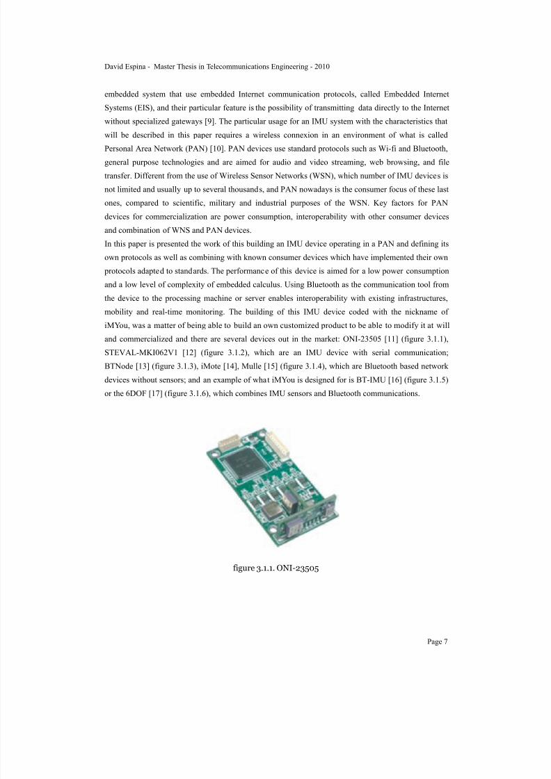
The iMYou device it has been built as an advanced prototype, which caused several problems on themounting and need for redesigning and replacement of some shapes of specific components (figure
4.1.1).
David Espina - Master Thesis in Telecommunications Engineering - 2010
Page 13
7/22/2019 Gyro With Avr
http://slidepdf.com/reader/full/gyro-with-avr 16/101
figure 4.1.1. iMYou v.4
4.1.1.Circuit board performance.
The iMYou has two differentiated states: programming mode and running mode. The programming
mode is 5V USB bus powered (figure 4.1.1.1). In this mode the battery charger is supplied with 5V
which are dropped to 3.7V for the battery to charge. When the battery is charging a multi-color led isemitting yellow light and when fully charged is emitting green light. The running mode works both
USB and battery powered. If the USB cable is disconnected the battery starts suppling 3.7V but the
programming is not enabled (figure 4.1.1.2).
For both USB and battery powered states, the voltage given to the inertial components, MCU and
bluetooth chip is 3.3V.
David Espina - Master Thesis in Telecommunications Engineering - 2010
Page 14

7/22/2019 Gyro With Avr
http://slidepdf.com/reader/full/gyro-with-avr 17/101
figure 4.1.1.1. USB Power
figure 4.1.1.2. Battery Power
David Espina - Master Thesis in Telecommunications Engineering - 2010
Page 15
7/22/2019 Gyro With Avr
http://slidepdf.com/reader/full/gyro-with-avr 18/101
Programming Mode
The USB is plugged to the iMYou device and it performs handshake with the USB-Serial converter,
which is implemented on the flash memory of this last component. With a boot loader implemented in
ADA [23] at MDH (boot_loader_init.exe), the PC communicates with the USB-Serial converter
simulating a serial communication using a virtual port. This boot loader sets the necessary fuse
configuration on the ATmega128 to prepare the programming mode as if a serial communication had
been established between the PC and the MCU. This is an special configuration of the USB-Serial
converter which will be explained in 4.1.2.Components called bit bang mode. The USB-Serial
converter uses three wires UART communication with the ATmega128.
When the programming mode is enabled in the MCU by the boot loader, the USB programming utility
can be used (usb_avr_programmer_16m.exe) to access its memory and write the program that will run
in the ATmega128. This utility has been also programmed with ADA and requires a file path for
the .hex version of the code running in the MCU, programmed with any environment that supportsATMEL products such as AVR Studio [24] or WinAVR [25]. An alternative way of programming is
using AVR JTAGICE mkII [26] which communicates directly with the ATmega128’s specific pins and
provides a debugger.
Running Mode
Every setup has been done and the device is ready to be powered and work. This device can run with
USB power or in a no wires configuration powered by the lithium battery. The USB feeds the USB-
Serial Converter and the battery charger. If it is powered by USB and the battery is connected, the
battery charger handles loading mode or stand-by for the battery. In case the USB connector is
removed the USB-Serial converter won’t be powered and the battery charger will have 0V on the USBVCC pin, so it will be power supplied by the battery. The voltage on the output of the battery charger
gets dropped to standard 3.3V by the low-drop regulator and feeds the inertial components, MCU and
bluetooth module. There is an On/Off switch between the low-drop voltage regulator and the VDD
reference to turn on/off the device when required.
Once all the components are fed by 3.3V the MCU governs the global operations, having a status LED
for information and a button controller for RESET operations (figure 4.1.1.3).
David Espina - Master Thesis in Telecommunications Engineering - 2010
Page 16
7/22/2019 Gyro With Avr
http://slidepdf.com/reader/full/gyro-with-avr 19/101
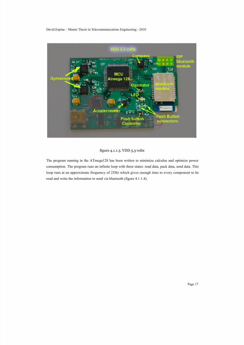
figure 4.1.1.3. VDD 3.3 volts
The program running in the ATmega128 has been written to minimize calculus and optimize power
consumption. The program runs an infinite loop with three states: read data, pack data, send data. This
loop runs at an approximate frequency of 25Hz which gives enough time to every component to be
read and write the information to send via bluetooth (figure 4.1.1.4).
David Espina - Master Thesis in Telecommunications Engineering - 2010
Page 17

7/22/2019 Gyro With Avr
http://slidepdf.com/reader/full/gyro-with-avr 20/101
figure 4.1.1.4. MCU program sequence.
4.1.2.Components.
In this section it is described which components have been used to build iMYou and their electrical
characteristics as well as why those were the components chosen. From the feeding voltage
perspective, the circuit board has two main areas that work at 5V (VDD_USB) and 3.3V (VDD) and a
conversion region which adapts the voltage from the battery charger to 3.3V (VDD_BATT). The
reason why there are 2 main areas is because the inertial motion components and the bluetooth module
work at 3.3V and a feeding voltage of 5V would cause malfunction or even destroy them.
The area fed with VDD_USB includes USB connector, USB-Serial converter and some specific pins
from the Battery charger.
The area fed with VDD includes the MCU, two gyroscopes, one accelerometer, one compass, a
16MHz oscillator, a bluetooth module, a push button controller, a push button, one LED and the output
pin from the voltage converter.
The voltage conversion area from VDD_USB to VDD that handles VDD_BATT includes some
specific pins from the battery charger, the battery connectors, one multicolor LED, the low-drop
voltage and a switch to enable/disable the voltage in the next area so it works as an On/Off switch.
USB connector: mini USB
David Espina - Master Thesis in Telecommunications Engineering - 2010
Page 18
7/22/2019 Gyro With Avr
http://slidepdf.com/reader/full/gyro-with-avr 21/101
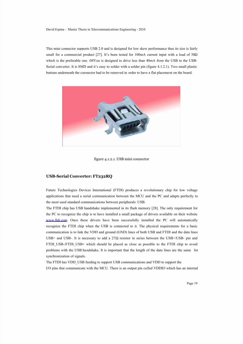
This mini connector supports USB 2.0 and is designed for low skew performance thus its size is fairly
small for a commercial product [27]. It’s been tested for 100mA current input with a load of 50!
which is the preferable one. iMYou is designed to drive less than 40mA from the USB to the USB-
Serial converter. It is SMD and it’s easy to solder with a solder pin (figure 4.1.2.1). Two small plastic
buttons underneath the connector had to be removed in order to have a flat placement on the board.
figure 4.1.2.1. USB mini connector
USB-Serial Converter: FT232RQ
Future Technologies Devices International (FTDI) produces a revolutionary chip for low voltage
applications that need a serial communication between the MCU and the PC and adapts perfectly to
the most used standard communications between peripherals: USB.
The FTDI chip has USB handshake implemented in its flash memory [28]. The only requirement for
the PC to recognize the chip is to have installed a small package of drivers available on their website
www.ftdi.com. Once these drivers have been successfully installed the PC will automatically
recognize the FTDI chip when the USB is connected to it. The physical requirements for a basic
communication is to link the VDD and ground (GND) lines of both USB and FTDI and the data lines
USB+ and USB-. It is necessary to add a 27! resistor in series between the USB+/USB- pin and
FTDI_USB-/FTDI_USB+ which should be placed as close as possible to the FTDI chip to avoid
problems with the USB handshake. It is important that the length of the data lines are the same for
synchronization of signals.
The FTDI has VDD_USB feeding to support USB communications and VDD to support the
I/O pins that communicate with the MCU. There is an output pin called VDDIO which has an internal
David Espina - Master Thesis in Telecommunications Engineering - 2010
Page 19

7/22/2019 Gyro With Avr
http://slidepdf.com/reader/full/gyro-with-avr 22/101
low-drop voltage converter for applications like iMYou which require both VDD_USB an VDD in the
FTDI, but is recommendable no to use it to have better stability. The pin that feeds the FTDI I/O pins
must be connected to VDD for 3.3V and compatibility with the rest of the components that use VDD.
It is necessary to place a 100nF capacitor next to the VDD and VDDIO pins for stability of thevoltage.
The pins used for communication with the MCU are TXD and RXD as input/output data lines, RTS#,
CTS#, DTR#, DSR# and RI# for handshake of the UART communication.
There are two packages available: FT232RQ (QFN-32) [29] and FT232RL (28-LD SSOP) [30]. The
election of the first one has compromised the construction and performance of iMYou and it would be
preferable to use the second shape in the future. The difference between these two shapes lies on the
difficulty of their placement and the testing. The first one is a Quad Flat No leads (QFN) with 32 pins
plus a heat sink for GND pin underneath. The second one is a Shrink Small-Outline Package (SSOP)
which has leads of a reasonable length for hand soldering (figure 4.1.2.2).
figure 4.1.2.2. FT232RQ and FT2323RL
The difficulty of knowing when every pin of the QFN component is correctly soldered as well as the
heat sink caused many problems of communications and burning several components while soldering
them. The RobotRingen circuit board and similar projects running at MDH use the SSOP package
which should have been the first choice for iMYou. The difference in the number of pins between the
two packages doesn’t affect the functioning of iMYou due to most of the extra pins from the QFN
package are test pins or extra GND pins. The heat sink purpose can be found at 4.2.2.Hardware
construction.
The data sheet shows multiple configurations for the FTDI to communicate with several different
components. The one chosen for the iMYou is show in figure 4.1.2.3.
David Espina - Master Thesis in Telecommunications Engineering - 2010
Page 20

7/22/2019 Gyro With Avr
http://slidepdf.com/reader/full/gyro-with-avr 23/101
figure 4.1.2.3. USB to MCU UART USB
At the FTDI website several testing tools can be found which will be described at 4.3.1.Tools and
environment.
Battery: CS-XEW01SL 3.7V Lithium
Due to the low consumption of the iMYou, the battery provides with hours of autonomy. The charging
is performed in some minutes once the USB cable is plugged in [31]. This battery has been used at
MDH for projects involving bluetooth nodes which power requirements can be comparable to the
iMYou.
When the battery is fully charged it provides around 4.1V and balances to 3.7V output after 8%
discharge. This discharge curve is very flat from 90% to 10%. When working under 10% of charge,
the voltage output drops considerably fast (figure 4.1.2.4) [32].
David Espina - Master Thesis in Telecommunications Engineering - 2010
Page 21

7/22/2019 Gyro With Avr
http://slidepdf.com/reader/full/gyro-with-avr 24/101
figure 4.1.2.4. Battery charge performance (green curve)
The size of the battery is 7 x 4.5 mm which matches the design of the iMYou but it would be
preferable to use a smaller size for commercialization (figure 4.1.2.5).
figure 4.1.2.5. Battery model CS-XEW01SL
Battery Charger: Max1811
David Espina - Master Thesis in Telecommunications Engineering - 2010
Page 22

7/22/2019 Gyro With Avr
http://slidepdf.com/reader/full/gyro-with-avr 25/101
Max1811 is a battery charger from MAXIM specially designed for Lithium batteries and to work
USB-powered [33]. The package is a 8 pin SOIC fairly easy to mount (figure 4.1.2.6). The
recommended configuration includes two capacitors, one electrolytic, connected to the positive
terminal of the battery. There is also a LED and a resistor from the CHG pin to the IN pin, which willlight during the charging process.
figure 4.1.2.6. Battery charger
If the battery is not connected, the VDD_USB goes through to the low-drop voltage changing from
5V to 4.2V due a drop in the battery charger. In case the USB is not connected, the VDD_BATT feeds
the voltage regulator and the MAX1811 will not work since there is no VDD_USB, which is power
efficient.
Low-drop voltage: AS1360 3.3V
This device is designed for very low consumption, giving up to 250mA while consuming only 1.5"A.
It supports a wide input voltage range and gives a fixed output of 3.3V. The key feature for this device
is that produces a very stable output with strict output voltage regulation tolerances (±0.5%) and
excellent line-regulation. It is suited for battery.powered and portable applications. The package is a
SMD SOT23 which is small but easy for hand-soldering (figure 4.1.2.7).
figure 4.1.2.7. SOT23
The output pin (VOUT) is connected, in series with an On/Off switch, to the VDD that feeds the
inertial motion components, MCU and bluetooth module.
David Espina - Master Thesis in Telecommunications Engineering - 2010
Page 23

7/22/2019 Gyro With Avr
http://slidepdf.com/reader/full/gyro-with-avr 26/101
Push button controller: LTC2950
This is an interface to control the performance of a physical push button. It balances the signal the
comes when the button is pressed until it’s released avoiding rings and peaks. Its input range is wide
and its power requirements very low. In figure 4.1.2.8 a push action is shown. PB is the input of the
controller, where the button is connected. EN is the enable output pin, that provides the voltage after
the controller has recognized the action.
figure 4.1.2.8. Push button action
Color LED and Multicolor LED
The color LED is ruled by the MCU to light when the board is running and the multicolor LED is used
by the battery charger to display whether the battery is charging or fully charged. Both components
require a resistor in series to VDD. The package is SOT23.
MCU: ATmega128
ATmega128 is an 8-bit Microcontroller from ATMEL [34] and belongs to the AVR family of micro
controllers [35]. It has a 128KBytes memory of In-system, self programable memory, which covers by
far the requirements for the iMYou firmware, using this less than a 4% of the memory available.
Some of the general characteristics of ATmega128 used at the iMYou firmware are the 8-bit Time/
Counter to handle interruptions and timeouts in bluetooth communication, 8 channel 10-bit Analog/
Digital converters, byte-oriented Two-wire serial interface, dual programmable serial USARTs,
David Espina - Master Thesis in Telecommunications Engineering - 2010
Page 24

7/22/2019 Gyro With Avr
http://slidepdf.com/reader/full/gyro-with-avr 27/101
Master/Slave SPI serial interface, SPI interface for In-System programming, JTAG interface, 2.7-5.5
V supported feeding.
The ATmega128 is the core of the iMYou, coordinating tasks between the inertial motion components
and the bluetooth module. It is also responsible to provide notifications about the power state of thecircuit board (On/Off). In programming mode the FTDI chip communicates with it with the UART0
port. The FTDI sets the bit bang mode to perform this USB to serial communications, explained in
section 4.1.3.Communications.
There are two versions of the chip available: ATmega128 and ATmega128L. The difference resides on
VDD and oscillator characteristics. ATmega128 can be powered from 4.5-5.5V and supports an
external oscillator up to 16MHz. ATmega128L can be powered from 2.7-5.5V but supports only up to
8MHz external oscillator. The iMYou device was designed after RobotRingen’ specifications and
having an external oscillator running at 16MHz was one of the initial conditions. Since the chip used
at RobotRingen is ATmega128 and the chip used at iMYou is ATmega128L, it is very important to
notice that the units used for programming are different. In the other hand, the performance of the program in the MCU of the iMYou device is not compromised by this issue. Despite this difference,
the design of the iMYou has kept the 16MHz oscillator all along (figure 4.1.2.9).
figure 4.1.2.9. ATmega128 VDD vs frequency of external Oscillator.
There are 64 pins available at ATmega128 from which 37 are used to build the iMYou system. A
detailed list of the components can be found in table 4.1.2.1.
ATmega128 Pin
SpecialFunction
Connected to Pin Description
PB0 SS Accelerometer &Bluetooth module
C S ( A c c e l )SPI_CS (BT)
UART handshake
PB1 SCK FTDI & Accelerometer &Bluetooth module
R I ( F T D I )S C L ( A c c e l )SPI_CLK (BT)
UART handshake
PB2 MOSI Accelerometer &Bluetooth module
S D A ( A c c e l )SPI_MISO (BT)
UART data line
PB3 MISO Accelerometer &Bluetooth module
S C O ( A c c e l )SPI_MOSI (BT)
UART data line
David Espina - Master Thesis in Telecommunications Engineering - 2010
Page 25

7/22/2019 Gyro With Avr
http://slidepdf.com/reader/full/gyro-with-avr 28/101
ATmega128 Pin
SpecialFunction
Connected to Pin Description
PB4 LED Notify power onthe board
PB5 Button Controller KILL Releases theenable output of the ButtonController
PB6 Button Controller INT Interrupt the button controllersystem after apush action
PD0 SCL Compass SCL TWI clock signal
PD1 SDA Compass SDA TWI data line
PD2 RXD1 Bluetooth Module UART_TX UART data line
PD3 TXD1 Bluetooth Module UART_RX UART data line
PD4 ICP1 Bluetooth Module UART_CTS UART handshake
PD5 XCK1 Bluetooth Module UART_RTS UART handshake
PD7 Compass DRDY Data Input
PE0 R X D 0 /PDI
FTDI TX UART data line
PE1 TXD0/ PD FTDI RX UART data line
PF1 ADC1 Gyroscope U8 and U12 HP ADC Input
PF2 ADC2 Gyroscope U8 VREF ADC Input
PF3 ADC3 Gyroscope U8 4xOUTY ADC Input
PF4 ADC4 Gyroscope U8 4xOUTX ADC Input
PF5 ADC5 Gyroscope U12 VREF ADC Input
PF6 ADC6 Gyroscope U12 4xOUTZ ADC Input
PF7 ADC7 Gyroscope U12 4xOUTY ADC Input
PG0 WR FTDI RTS UART handshake
PG1 RD FTDI CTS UART handshake
PG2 ALE FTDI DTR UART handshake
PG3 TOSC2 FTDI DSR UART handshake
RESET FTDI DCD UART handshake
David Espina - Master Thesis in Telecommunications Engineering - 2010
Page 26

7/22/2019 Gyro With Avr
http://slidepdf.com/reader/full/gyro-with-avr 29/101
ATmega128 Pin
SpecialFunction
Connected to Pin Description
XTAL2 External oscillator Output External oscillatorOutput
XTAL1 External oscillator Input External oscillatorInput
AREF Analog Ground AGND Analog referencefor ACD
AVCC Supply Voltage VDD Supply Voltage for ADC
GND Digital Ground GND Digital Referencef o r e v e r ycomponent
VCC Supply Voltage VDD Supply Voltage forD i g i t a lComponents
Table 4.1.2.1. Pinout ATmega128 for iMYou.
In figure 4.1.2.10, the pinout of the ATmega128 is shown as is provided by the manufacturer.
David Espina - Master Thesis in Telecommunications Engineering - 2010
Page 27

7/22/2019 Gyro With Avr
http://slidepdf.com/reader/full/gyro-with-avr 30/101
figure 4.1.2.10. ATmega128 Pinout.
iMYou is using four different physical technologies to establish connection between the components
on the board. These are Universal Synchronous & Asynchronous serial Receiver and Transmitter
(USART), analog to digital converters (ADC), serial digital transmission (pin to pin with no protocol),
and Two-wire Serial Interface (TWI). Both USART and TWI are capable of protocols such as I2C,
SPI, RS-232.
For instance, the FTDI, Accelerometer and Bluetooth module are connected to the UART0 using
different protocols. The FTDI is using synchronous serial communication, but the other two
components are using SPI. The Chip Select pin PB0(SS) is used determine which component is
making use of the transmission lines.
To execute the analog ADC conversions, the ATmega128 features a 10-bit successive approximation
ADC. The ADC is connected to an 8-channel Analog Multiplexer which allows 8 single-ended voltage
inputs constructed from the pins of Port F. The single-ended voltage inputs refer to 0V (GND). The
ADC contains a Sample and Hold circuit which ensures that the input voltage to the ADC is held at a
constant level during conversion.
David Espina - Master Thesis in Telecommunications Engineering - 2010
Page 28

7/22/2019 Gyro With Avr
http://slidepdf.com/reader/full/gyro-with-avr 31/101
Those components which communicate with the MCU without no standard protocol using serial
digital transmission, need software implementation of the protocol. These is the case of the external
oscillator, LED and push button controller.
The compass uses TWI which needs only two connections with the host controller: SCL for clocksynchronization and SDA for data transmission.
Every microcontroller has the possibility to activate external interrupts. The External Interrupts are
triggered by the INT7:0 pins. Observe that, if enabled, the interrupts will trigger even if the INT7:0
pins are configured as outputs. This feature provides a way of generating a software interrupt. The
External Interrupts can be triggered by a falling or rising edge or a low level. iMYou is programmed to
attend interrupts from the ADC, which notifies when the data from the gyroscopes is ready to be read
and converted to a digital signal.
The original design of the iMYou was conceived to use USB-serial to communicate with the PC and
load the program on the flash memory of the ATmega128. Since this worked perfectly at theRobotRingen it was assumed that same successful performance would occur at the iMYou, which it
was not. To solve problem, a physical upgrade was added to the pins of the Port F to include JTAG
operations, being able to program the MCU via serial communication.
An important issue that compromised the development of the iMYou was the package size of the
ATmega128. There are two available versions of the chip referring package information: 64A and
64M1. The package with the label 64A conforms to 64-lead, 14 x 14 mm body size, 1.0 body
thickness, 0.8 mm Lead Pitch. This package is also know as Thin Profile Plastic Quad Flat Package
(TQFP) (figure 4.1.2.11). The other package, 64M1 conforms to a 64-pad, 9 x 9 mm body size, 0.5
mm Lead Pitch, 5.40 mm exposed pad. This package is also known as Micro Lead Frame Package(MLF) (figure 4.1.2.12).
figure 4.1.2.11. ATmega128 TQFP package.
David Espina - Master Thesis in Telecommunications Engineering - 2010
Page 29

7/22/2019 Gyro With Avr
http://slidepdf.com/reader/full/gyro-with-avr 32/101
figure 4.1.2.12. ATmega128 MLF package.
The RobotRingen uses 64A package which is also the a common model used in prototypes. This
package is easy to place and solder by hand, being able to check easily connectivity in case there
would be any short circuit. The iMYou was conceived with a market scope and the size was a
handicap. For that reason a mistake occurred during the first stages of the design process, and the
smallest sizes of every available component were chosen instead of a proper prototype. The fact that
the first versions of the circuit board were mounted by hand and a solder pin, drove to several errors.
The MLF package has a heat sink which must be connected to GND. It is a big pad that sucks the heat
out of the component if connected to a rather big surface. This heat sink and the fact that the pads are
also below the component, makes is very difficult to solder by hand. Having a perfect alignment of
every pad referred to the correspondent pads in the circuit board is also difficult to set by hand and a
microscope, due to the small size and the improper tools for that operation.
For future implementations and upgrades of the iMYou, building a proper prototype with packages
that are easy to solder in a basic electronic laboratory is highly recommended.
Resistors and Capacitors
All the passive elements described in this section as a back up for the inertial components, MCU,
bluetooth module, USB-serial interface, etc. were chosen to feat specifications of the iNemo and the
RobotRingen. For the market scope reason explained above, the smallest size of the packages for these
resistors (Rs) and capacitors (Cs) were chosen. This size was the standard 0402, which is also difficult
so align and hand solder in a lab like the one described. The same decision should be taken when
future upgrades of the iMYou will take place, and a bigger size should be chosen, such as 0608 (figure
4.1.2.13).
David Espina - Master Thesis in Telecommunications Engineering - 2010
Page 30

7/22/2019 Gyro With Avr
http://slidepdf.com/reader/full/gyro-with-avr 33/101
figure 4.1.2.13. Rs and Cs 0402 package.
Oscillator 16MHz
As a ported project from RobotRingen, the iMYou decide included an external oscillator of 16MHz to
replace the internal one from the ATmega128 that runs at a maximum frequency of 8MHz. As it’s been
exposed in the previous section, the design requirements changed and this oscillator won’t have a rollin the system’s performance. The only changes introduced by using the internal oscillator are in the
boot loader utility, the USB-serial programmer utility and the configuration of the JTAG options in the
PC. It doesn’t need extra capacitors as shown at ATmega128 data sheet since those required capacitors
are integrated in the MCU.
Accelerometer: LIS331DLH
Manufactured by ST Electronics at a low price (5$ unit), this is a “nano component” due to its reduced
size (3 x 3 mm). It has a very low consumption mode which makes is perfect for low-power designs.
In particular it goes down to 10 "A (figure 4.1.2.14) . It has a range of voltage feeding of 2.16 - 3.6 V,
which makes it perfect for iMYou 3.3V VDD. It supports both I2C and SPI protocols and an 16bitaccuracy on the output. In this particular project the protocol used is SPI, which works over UART as
physical protocol. As a features of the device, it has sleep to wake up function, free fall detection and
motion detection. Only the third named feature is implemented in the firmware of the iMYou.
figure 4.1.2.14. Accelerometer LIS331DLH.
David Espina - Master Thesis in Telecommunications Engineering - 2010
Page 31

7/22/2019 Gyro With Avr
http://slidepdf.com/reader/full/gyro-with-avr 34/101
The LIS331DLH is only available in small thin plastic land grid array package (LGA), which has pads
under the component and makes it difficult to mount and align by hand soldering.
The reason why this accelerometer was chosen is because it is part of the iNemo project, as well as the
other inertial components. One of the prerequisites of this project was to match its functionality withsuch projects named before (iNemo and RobotRingen).
There are some additional capacitors and resistors required to the proper acquisition of the output and
stability of signals. The same as in every other component on the board, there is a 100nF capacitor
close to the VDD pin (figure 4.1.2.15).
figure 4.1.2.15. Accelerometer schematic.
There has been set a coordinates reference system on the board which is used to calibrate the inertial
motion components and also as a equilibrium position. This reference system has been taken from
iNemo project in which the X, Y, Z axis of the board has been set as shown in figure 4.1.2.16.
David Espina - Master Thesis in Telecommunications Engineering - 2010
Page 32

7/22/2019 Gyro With Avr
http://slidepdf.com/reader/full/gyro-with-avr 35/101
figure 4.1.2.16. Coordinates reference system and accelerometer orientation.
Compass: Honeywell HMC5843
The Honeywell HMC5843 is a 3-axes magnetometer designed for low field magnetic sensing with a
digital interface for applications such as low cost compassing and magnetometer. Due to its small size
is perfect to integrated products (4 x 4 mm) (figure 4.1.2.17).
figure 4.1.2.17. Compass Honeywell HMC5843.
The iNemo project provided the suggestions for the schematic which were followed to keep
compatibility (figure 4.1.2.18). Notice the 100nF extra capacitor for the VDD pins and other
configurations to give stability to the output signals.
David Espina - Master Thesis in Telecommunications Engineering - 2010
Page 33
7/22/2019 Gyro With Avr
http://slidepdf.com/reader/full/gyro-with-avr 36/101
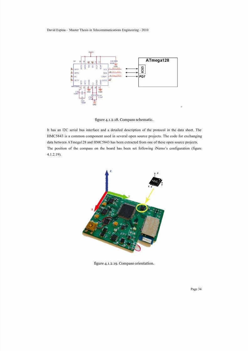
figure 4.1.2.18. Compass schematic.
It has an I2C serial bus interface and a detailed description of the protocol in the data sheet. The
HMC5843 is a common component used in several open source projects. The code for exchanging
data between ATmega128 and HMC5843 has been extracted from one of these open source projects.
The position of the compass on the board has been set following iNemo’s configuration (figure
4.1.2.19).
figure 4.1.2.19. Compass orientation.
David Espina - Master Thesis in Telecommunications Engineering - 2010
Page 34

7/22/2019 Gyro With Avr
http://slidepdf.com/reader/full/gyro-with-avr 37/101
Gyroscopes: LPR530AL and LPY530AL
Produced by ST Electronics, both the LPR530AL and the LPY530AL have a full scale of ±300°/s.
Both components has the same physical and mechanical characteristics. They are dual axes able to
measure angular rate along pitch and yaw/roll axes. The reason why there are two gyroscopes 2 is thatLPR530AL provides the data of axis Y and X, while LPY530AL provides the data of axis Z and Y.
There is redundant information of axis Y. An average measure of the both values is packed and sent
over bluetooth.
The acquisition of the signals is done by ADC which is taken place at PORT F of the ATmega128.
Several passive components are needed to filter noise and provide signal with good quality (figure
4.1.2.20 and figure 4.1.2.21).
figure 4.1.2.20.LPR530AL schematic.
David Espina - Master Thesis in Telecommunications Engineering - 2010
Page 35
7/22/2019 Gyro With Avr
http://slidepdf.com/reader/full/gyro-with-avr 38/101
figure 4.1.2.21.LPY530AL schematic.
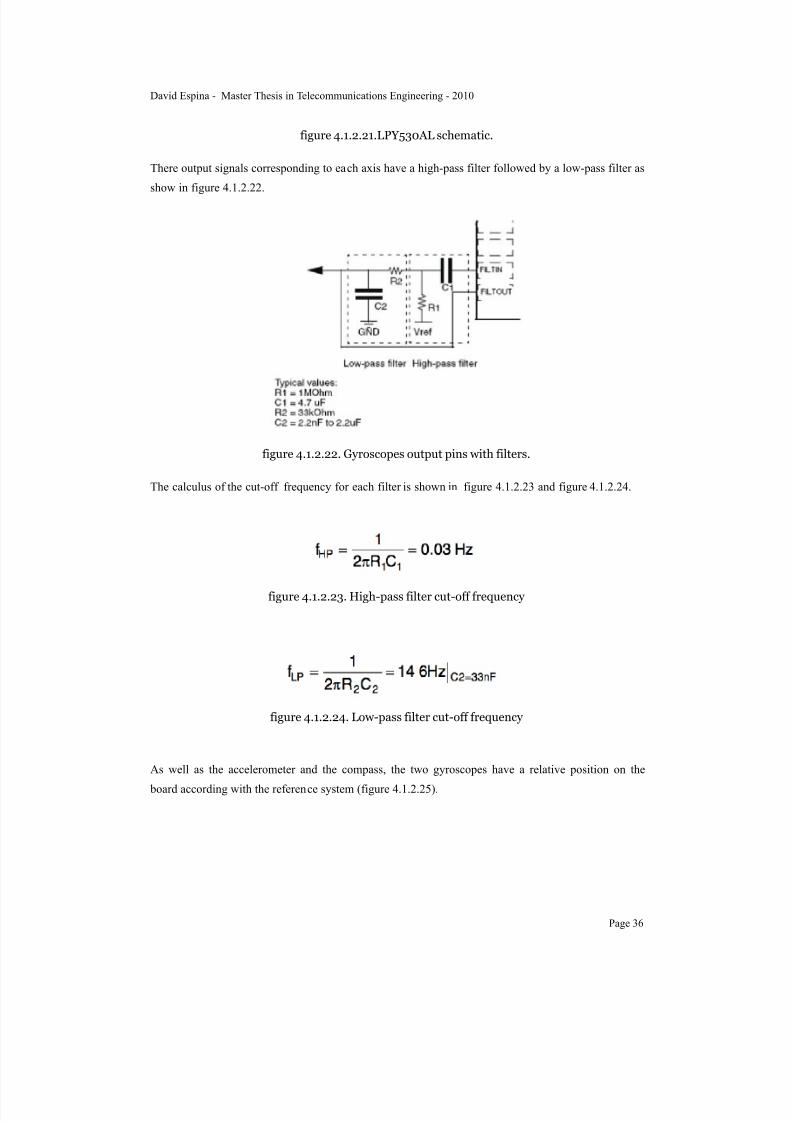
There output signals corresponding to each axis have a high-pass filter followed by a low-pass filter as
show in figure 4.1.2.22.
figure 4.1.2.22. Gyroscopes output pins with filters.
The calculus of the cut-off frequency for each filter is shown in figure 4.1.2.23 and figure 4.1.2.24.
figure 4.1.2.23. High-pass filter cut-off frequency
figure 4.1.2.24. Low-pass filter cut-off frequency
As well as the accelerometer and the compass, the two gyroscopes have a relative position on the
board according with the reference system (figure 4.1.2.25).
David Espina - Master Thesis in Telecommunications Engineering - 2010
Page 36

7/22/2019 Gyro With Avr
http://slidepdf.com/reader/full/gyro-with-avr 39/101
figure 4.1.2.25. Gyroscopes orientation.
Bluetooth module: Mitsumi WML-C40
This bluetooth module complies with Bluetooth specification version 2.0+EDR Class1 power level
and integrates RF and base-band controller in ultra small package (figure 4.1.2.26).
figure 4.1.2.26
This device supports BCSP and H4, both of them under UART; and also supports USB.
In a firmware level WML-C40 doesn’t implement Serial Port Profile Bluetooth ® commands, which
makes the programmer write his own routines and commands following the Bluecore documentation
for host controllers [36].
Some important technical characteristics are listed below:
• 3.3 V supply voltage
• 2 dBi gain integrated antenna.
• Carrier frequency 2402 MHz to 2480 MHz.
David Espina - Master Thesis in Telecommunications Engineering - 2010
Page 37

7/22/2019 Gyro With Avr
http://slidepdf.com/reader/full/gyro-with-avr 40/101
• Modulation method GFSK, 1Mbps, 0.5BT Gaussian, #/4-DQPSK, 2Mbps, Square-root Raised
Cosine with 0.4 roll-off factor, 8DPSK, 3 Mbps, Square-root Raised Cosine with 0.4 roll-off factor.
• Maximum data rate: asymmetric 2178.1 kbps/177.1 kbps; symmetric 1306.9 kbps/1306.9kbps.
• Receiving signal rate -80 to 0 dBm• Receiver IF frequency 1.5 MHz lower heterodyne.
According to the ATmega128 transmission speed characteristics and the oscillator running at 8 MHz,
the special register UBRR parameter must set as the following example shows in figure 4.1.2.27.
figure 4.1.2.27. Baud rate and oscillator frequency values.
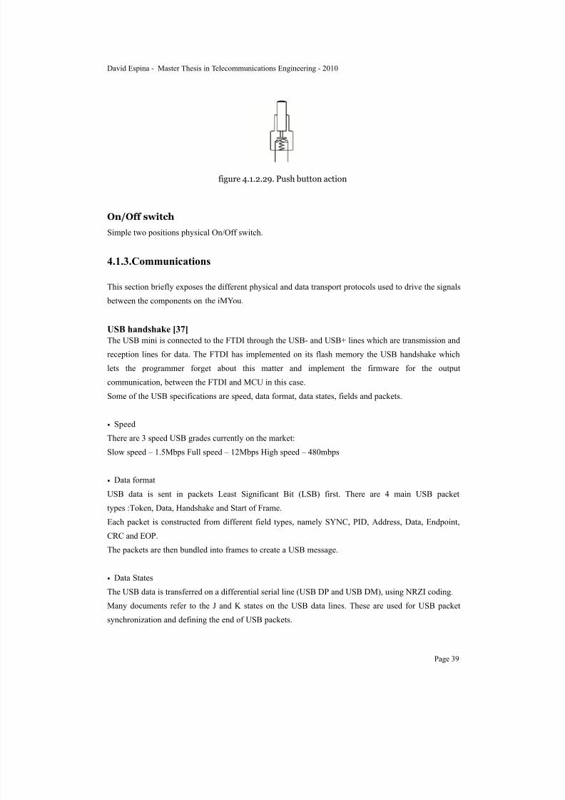
Push button
Simple physical thumb push-auto release button (figure 4.1.2.28 and figure 4.1.2.29).
figure 4.1.2.28. Push button
David Espina - Master Thesis in Telecommunications Engineering - 2010
Page 38
7/22/2019 Gyro With Avr
http://slidepdf.com/reader/full/gyro-with-avr 41/101
figure 4.1.2.29. Push button action
On/Off switch
Simple two positions physical On/Off switch.
4.1.3.Communications
This section briefly exposes the different physical and data transport protocols used to drive the signals
between the components on the iMYou.
USB handshake [37]
The USB mini is connected to the FTDI through the USB- and USB+ lines which are transmission and
reception lines for data. The FTDI has implemented on its flash memory the USB handshake which
lets the programmer forget about this matter and implement the firmware for the output
communication, between the FTDI and MCU in this case.
Some of the USB specifications are speed, data format, data states, fields and packets.
• Speed
There are 3 speed USB grades currently on the market:
Slow speed – 1.5Mbps Full speed – 12Mbps High speed – 480mbps
• Data format
USB data is sent in packets Least Significant Bit (LSB) first. There are 4 main USB packet
types :Token, Data, Handshake and Start of Frame.
Each packet is constructed from different field types, namely SYNC, PID, Address, Data, Endpoint,
CRC and EOP.
The packets are then bundled into frames to create a USB message.
• Data States
The USB data is transferred on a differential serial line (USB DP and USB DM), using NRZI coding.
Many documents refer to the J and K states on the USB data lines. These are used for USB packet
synchronization and defining the end of USB packets.
David Espina - Master Thesis in Telecommunications Engineering - 2010
Page 39

7/22/2019 Gyro With Avr
http://slidepdf.com/reader/full/gyro-with-avr 42/101
A J state has a differential signal on USB DP and USB DM >= +300mV. A K state has a differential
signal on USB DP and USB DM >= -300mV.
A Single Ended Zero (SE0) is where both USB DM and USB DM are at 0V.
• Fields
Fields are the building blocks of a USB packet. There are seven types of fields:
- Sync - Packet identifier - Address - Endpoint - Data - CRC - EOP
• Packets
There are four different types of USB packets:
- TOKEN - DATA - Handshake - Start of Frame
UART [38]
Universal Asynchronous Receive & Transmit (UART) is part of the standard Universal SynchronousAsynchronous Receive & Transmit(USART) and is hardware support for communications protocols
such as I2C and SPI.
USAR doesn’t have fixed a protocol (7,8 or 9 bit with or without Receiver Addressing) but is normally
capable of protocols that incorporate:
Asynchronous - usually RS232, RS422 & RS485 - two wires TX & RX with pre-defined data rate and
receiving synchronized to incoming data stream. No pre-defined master or slave and may be full
duplex.
Synchronous - two wires, fixed Clock (from single master) and Data - half-duplex - 8 or 9 bit & no
slave address
The UART takes bytes of data and transmits bit by bit in a sequential fashion. At the destination, a
second UART re-assembles the bits into complete bytes. Serial transmission of digital information
(bits) through a single wire or other medium is much more cost effective than parallel transmission
through multiple wires. A UART is used to convert the transmitted information between its sequential
and parallel form at each end of the link. Each UART contains a shift register which is the
fundamental method of conversion between serial and parallel forms.
In asynchronous transmission, the sender doesn’t have to send a clock signal to the receiver. Instead,
the sender and receiver must agree on timing parameters in advance and special bits are added to each
word which are used to synchronize the sending and receiving units.
When a word is given to the UART for Asynchronous transmissions, a bit called the "Start Bit" is
added to the beginning of each word that is to be transmitted. The Start Bit is used as a flag, to force
synchronization into the clock in the receiver, with the clock in the transmitter; and to alert the receiver
David Espina - Master Thesis in Telecommunications Engineering - 2010
Page 40

7/22/2019 Gyro With Avr
http://slidepdf.com/reader/full/gyro-with-avr 43/101
that a word of data is about to be sent. These two clocks must be accurate enough to not have the
frequency drift by more than 10% during the transmission of the remaining bits in the word.
FTDI Bit-bang mode [39]Bit-bang mode or Bit Banging is a slow method used to simulate UART communications in a device
that doesn’t support such standard. In this case the FT232RQ.
This mode changes the 8 data lines on the FT232RQ data and control lines to an 8 bit bi-directional
bus. The pins required in the FTDI device are TXD, RXD, RTS, DTR, DSR, DCD and RI.
Any data written to the device in the normal way will be self clocked onto the data pins which must be
programmed as outputs. Each pin can be set as an input or an output independent of the other pins. The
rate of clocking out the data is controlled by the baud rate generator.
The commands of interest are :
• FT_SetBaudRate(ftHandle : Dword ; BaudRate : Dword) : FT_Result;• FT_SetBitMode (ftHandle : Dword ; ucMask , ucEnable : Byte) : FT_Result;
• FT_GetBitMode ( ftHandle : Dword ; pucData : pointer ) : FT_Result;
There is a C/C++ library with all the commands and configurations, available on the FTDI website.
Figure 4.1.3.1 shows an analogy between the holes in player piano roll representing a bit map of the
key’s state over time, being similar to an array passed to a write function, which represents a bit map
of the data lines’ state over time.
figure 4.1.3.1. Analogy between bit-banging and a player piano roll
David Espina - Master Thesis in Telecommunications Engineering - 2010
Page 41

7/22/2019 Gyro With Avr
http://slidepdf.com/reader/full/gyro-with-avr 44/101
SPI [40]
SPI is a communication protocol over USART - normally a three wire, synchronous, single master,
multi-slave & duplex system. Wires are Master-Clock, Data In, Data Out & Slave Select(n).
• Synchronous protocol
The clock signal is provided by the master to provide synchronization. The clock signal controls when
data can change and when it is valid for reading. Since SPI is synchronous, it has a clock pulse along
with the data. RS-232 and other asynchronous protocols do not use a clock pulse, but the data must be
timed very accurately. The SPI has a clock signal and so the clock can vary without disrupting the
data. The data rate will simply change along with the changes in the clock rate. This makes SPI ideal
when the microcontroller is being clocked imprecisely, such as by a RC oscillator.
• Master-Slave protocol
Only the master device can control the clock line, SCK. No data will be transferred unless the clock is
manipulated. All slaves are controlled by the clock which is manipulated by the master device. The
slaves may not manipulate the clock. The SSP configuration registers will control how a device will
respond to the clock input.
• Data Exchange protocol
As data is being clocked out, new data is also being clocked in. When one “transmits” data, the
incoming data must be read before attempting to transmit again. If the incoming data is not read, then
the data will be lost and the SPI module may become disabled as a result. Always read the data after a
transfer has taken place, even if the data has no use in your application. Data is always “exchanged”
between devices. No device can just be a “transmitter” or just a “receiver” in SPI. However, each
device has two data lines, one for input and one for output. These data exchanges are controlled by the
clock line, SCK, which is controlled by the master device. Often a slave select signal will control
when a device is accessed. This signal must be used for when more than one slave exists in a system,
but can be optional when only one slave exists in the circuit. As a general rule, it should be used.
This signal is known as the SS signal and stands for “Slave Select.” It indicates to a slave that the
master wishes to start an SPI data exchange between that slave device and itself. The signal is most
often active low, so a low on this line will indicate the SPI is active, while a high will signal inactivity.
It is often used to improve noise immunity of the system. Its function is to reset the SPI slave so that it
is ready to receive the next byte.
David Espina - Master Thesis in Telecommunications Engineering - 2010
Page 42

7/22/2019 Gyro With Avr
http://slidepdf.com/reader/full/gyro-with-avr 45/101
In SPI, data typically changes during the rising or falling edge of SCK. This is how the data is
synchronized with the clock signal. Logically, the point at which data is read is opposite from when it
changes. The data is valid at the point of reading.
TWI and I2C [41]
Philips developed Inter-IC bus, or I2C, in the 1980s. I2C is a low-bandwidth, short distance protocol
for on board communications. All devices are connected through two wires (Two Wire Interface:
TWI): serial data (SDA) and serial clock (SCL) (figure 4.1.3.2).
figure 4.1.3.2 I2C Implementation
I2C has a master/slave protocol. The master initiates the communication. The sequence of events are:
1. The Master device issues a start condition. This condition informs all the slave devices to listen on
the serial data line for instructions.
2. The Master device sends the address of the target slave device and a read/write flag.
3. The Slave device with the matching address responds with an acknowledgement signal.
4. Communication proceeds between the Master and the Slave on the data bus. Both the master andslave can receive or transmit data depending on whether the communication is a read or write. The
transmitter sends 8-bits of data to the receiver which replies with a 1-bit acknowledgement.
5. When the communication is complete, the master issues a stop condition indicating that
everything is done.
A graph of the communication protocol is show in figure 4.1.3.3. Since there are only two wires, this
protocol includes the extra overhead of an addressing mechanism and an acknowledgement
mechanism.
figure 4.1.3.3. I2C communication protocol
David Espina - Master Thesis in Telecommunications Engineering - 2010
Page 43

7/22/2019 Gyro With Avr
http://slidepdf.com/reader/full/gyro-with-avr 46/101
ADC [42]
The ADC contains a Sample and Hold circuit which ensures that the input voltage to the ADC is held
at a constant level during conversion. The ADC converts an analog input voltage to a 10-bit digital
value through successive approximation. The minimum value represents GND and the maximumvalue represents the voltage on the AREF pin minus 1 LSB. The analog input channel is selected by
writing to the MUX bits in ADMUX. Any of the ADC input pins, as well as GND and a fixed band-
gap voltage reference, can be selected as single ended inputs to the ADC. The ADC is enabled by
setting the ADC Enable bit, ADEN in ADCSRA. Voltage reference and input channel selections will
not go into effect until ADEN is set. The ADC does not consume power when ADEN is cleared, so it is
recommended to switch off the ADC before entering power saving sleep modes. The ADC generates a
10-bit result which is presented in the ADC Data Registers, ADCH and ADCL. By default, the result is
presented right adjusted, but can optionally be presented left adjusted by setting the ADLAR bit in
ADMUX. The ADC has its own interrupt which can be triggered when a conversion completes. When
ADC access to the data registers is prohibited between reading of ADCH and ADCL, the interrupt willtrigger even if the result is lost.
Starting the conversion
A single conversion is started by writing a logical one to the ADC Start Conversion bit, ADSC. This
bit stays high as long as the conversion is in progress and will be cleared by hardware when the
conversion is completed. If a different data channel is selected while a conversion is in progress, the
ADC will finish the current conversion before performing the channel change. In Free Running mode,
the ADC is constantly sampling and updating the ADC Data Register. Free Running mode is selected
by writing the ADFR bit in ADCSRA to one. The first conversion must be started by writing a logical
one to the ADSC bit in ADCSRA. In this mode the ADC will perform successive conversions
independently of whether the ADC Interrupt Flag, ADIF is cleared or not.
By default, the successive approximation circuitry requires an input clock frequency between 50 kHz
and 200 kHz to get maximum resolution. If a lower resolution than 10 bits is needed, the input clock
frequency to the ADC can be higher than 200 kHz to get a higher sample rate.
The ADC module contains a prescaler, which generates an acceptable ADC clock frequency from any
CPU frequency above 100 kHz. The prescaling is set by the ADPS bits in ADCSRA. The prescaler
starts counting from the moment the ADC is switched on by setting the ADEN bit in ADCSRA. The
prescaler keeps running for as long as the ADEN bit is set, and is continuously reset when ADEN is
low. When initiating a single ended conversion by setting the ADSC bit in ADCSRA, the conversion
starts at the following rising edge of the ADC clock cycle.
When a conversion is complete, the result is written to the ADC data registers, and ADIF is set. In
single conversion mode, ADSC is cleared simultaneously. The software may then set ADSC again, and
a new conversion will be initiated on the first rising ADC clock edge.
In Free Running mode, a new conversion will be started immediately after the conversion completes,
while ADSC remains high.
David Espina - Master Thesis in Telecommunications Engineering - 2010
Page 44
7/22/2019 Gyro With Avr
http://slidepdf.com/reader/full/gyro-with-avr 47/101
H4 Bluetooth® [36]
Bluetooth is designed to provide power-efficient, low-cost short range radio communications, It has
evolved from being an specific RF solution to a global technology specification for wirelesscommunication between portable devices, desktop machines and peripherals.
Bluetooth devices operate in the 2.4GHz band which is a globally available frequency band ensuring
communication compatibility worldwide.
Bluetooth supports two kinds of links: Asynchronous Connectionless (ACL) links for data
transmission and Synchronous Connection oriented (SCO) links for audio/voice transmission. The
gross Bluetooth data rate is 1 Mbps while the maximum effective rate on an asymmetric ACL link is
721 Kbps in either direction and 57.6 Kbps in the return direction.
Bluetooth is a master/slave communication and the devices are symmetric in that the same device may
operate as a master and also the slave. Each radio has a 48-bit unique device address (BD_ADDR) that
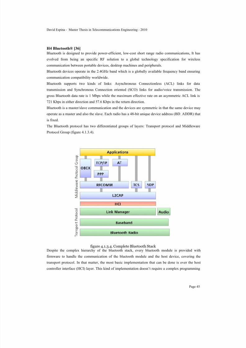
is fixed.The Bluetooth protocol has two differentiated groups of layers: Transport protocol and Middleware
Protocol Group (figure 4.1.3.4).
figure 4.1.3.4. Complete Bluetooth Stack Despite the complex hierarchy of the bluetooth stack, every bluetooth module is provided with
firmware to handle the communication of the bluetooth module and the host device, covering the
transport protocol. In that matter, the most basic implementation that can be done is over the host
controller interface (HCI) layer. This kind of implementation doesn’t require a complex programming
David Espina - Master Thesis in Telecommunications Engineering - 2010
Page 45
7/22/2019 Gyro With Avr
http://slidepdf.com/reader/full/gyro-with-avr 48/101
but it doesn’t support standard protocols from upper layers such as Serial Port Profile. This fact
implies that the device won’t be able to communicate with standard devices and there must to be
implemented an specific application to handle this communication.
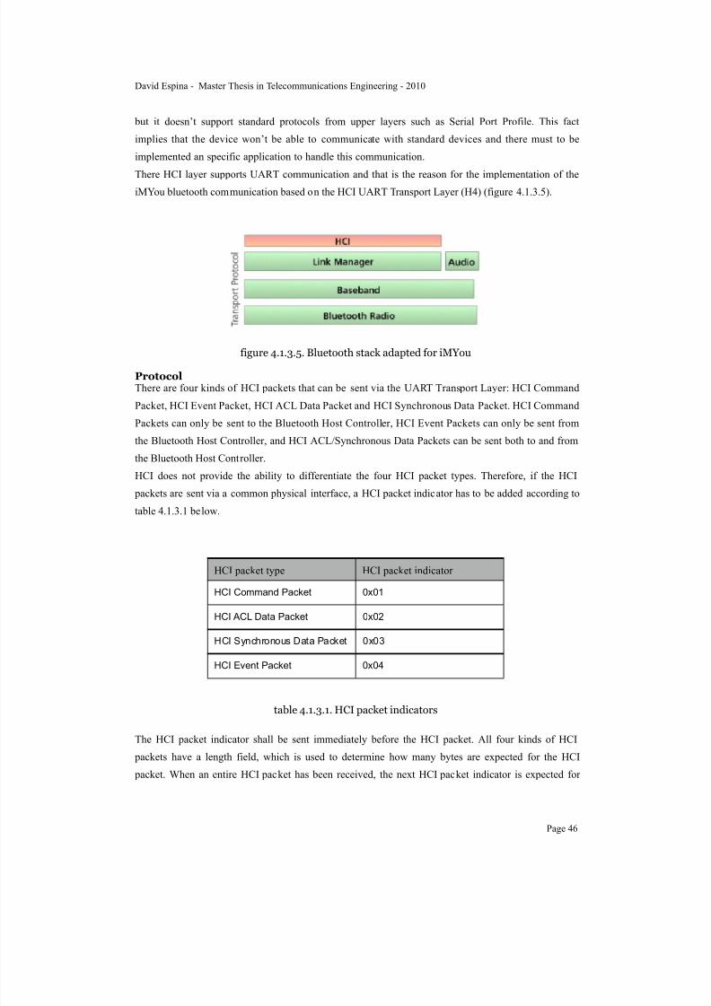
There HCI layer supports UART communication and that is the reason for the implementation of theiMYou bluetooth communication based on the HCI UART Transport Layer (H4) (figure 4.1.3.5).
figure 4.1.3.5. Bluetooth stack adapted for iMYou
ProtocolThere are four kinds of HCI packets that can be sent via the UART Transport Layer: HCI Command
Packet, HCI Event Packet, HCI ACL Data Packet and HCI Synchronous Data Packet. HCI Command
Packets can only be sent to the Bluetooth Host Controller, HCI Event Packets can only be sent from
the Bluetooth Host Controller, and HCI ACL/Synchronous Data Packets can be sent both to and from
the Bluetooth Host Controller.
HCI does not provide the ability to differentiate the four HCI packet types. Therefore, if the HCI
packets are sent via a common physical interface, a HCI packet indicator has to be added according to
table 4.1.3.1 below.
HCI packet type HCI packet indicator
HCI Command Packet 0x01
HCI ACL Data Packet 0x02
HCI Synchronous Data Packet 0x03
HCI Event Packet 0x04
table 4.1.3.1. HCI packet indicators
The HCI packet indicator shall be sent immediately before the HCI packet. All four kinds of HCI
packets have a length field, which is used to determine how many bytes are expected for the HCI
packet. When an entire HCI packet has been received, the next HCI packet indicator is expected for
David Espina - Master Thesis in Telecommunications Engineering - 2010
Page 46

7/22/2019 Gyro With Avr
http://slidepdf.com/reader/full/gyro-with-avr 49/101
the next HCI packet. Over the UART Transport Layer, only HCI packet indicators followed by HCI
packets are allowed.
Flow control with RTS/CTS lines is used to prevent temporary UART buffer overrun. It should not be
used for flow control of HCI, since HCI has its own flow control mechanisms for HCI commands,HCI events and HCI data. If CTS is 1, then the Host/Host Controller is allowed to send. If CTS is 0,
then the Host/Host Controller is not allowed to send.
4.2.Hardware
The implementation of the hardware has taken the largest load of work in this project. It started with
the gathering of all the information needed to design the first draw of the circuit board.
A pre-bill of materials was written down following the RobotRingen specifications about the USB-
Serial communication, and iNemo project specifications about the inertial motion components.
After the list was completed and revised, the data sheet of every component was reviewed to makesure that all the electrical conditions (VDD values, digital/analog ground conditions, passive elements
needed).
Then the schematic of iMYou started to be drawn using Multisim from National Instruments [43]. The
components are represented with a box with as many connections as pins has the component. It is
important to name every part (component) and every pin, since the schematic is under several changes.
Once the schematic was drawn, the materials are ordered to the local distributor. Most of the
components are in stock and the average wait time is 5 working days. There were some delays with the
ordering of the components from ST Electronics (gyroscopes and accelerometer). The reason was a
miss understanding with the factory in Sicily, Italy, which delayed the mounting of the first board two
weeks.After the schematic was complete and all the connections verified, the schematic was exported to
Ultiboard, the layout tool [44].
There are some parameters that needed configuration on the project properties. These parameters
referred to the physical restrictions that every component, pin, pad, etc. must strictly follow.
These parameters are:
• number of layers: 4 layers, Top, inner 1, inner 2 and bottom.
• width of lines: 1.5 to 2 mm for data lines, 3 mm for power lines (VDD, GND).
• clearance between lines: minimum 1.5 mm.
•clearance between pads: depending of the date sheet for each component.
• annular ring diameter: 0.7 mm
• drill diameter: 0.3 mm
• minimum distance to a hole: 1.5 mm.
David Espina - Master Thesis in Telecommunications Engineering - 2010
Page 47

7/22/2019 Gyro With Avr
http://slidepdf.com/reader/full/gyro-with-avr 50/101
In the layout environment all the components are placed outside the border outline of the circuit design
and must be placed in the desirable position to start drawing the lines between pins. When it is
necessary, a hole through the board is placed to avoid crossing lines.
The hardware design has been drawn keeping always in mind that the inner layer 1 is connected toVDD, the inner layer 2 is connected to GND and both Top and bottom layers have a power plane in all
the non used surface, and this connected to GND. This means that those lines which are not power
lines, were drawn first.
This process suffered three different redesigns due to several problems detected after the
manufacturing of the board.
When the board comes from the manufacturer every component is revised previous soldering, the
check alignment, size of the pads and possible mounting strategies. Every time the board is sent to the
manufacturer, it took three weeks to be delivered. During waiting time, the firmware of the iMYou was
designed.
4.2.1.Hardware design
The schematic has to be visual for identification of components and connexions. Every representation
of a component has footprint attached (blank by default). This footprint is a format readable by
Ultiboard to place the correspondent size for every component. Most of the sizes can be found at the
footprints library, such as SOT23 or 0402. Other footprints are not standard and must be designed first
in Multisim as a generic component with the exact number of pins, and afterwards in Ultiboard,
introducing the sizes of the package given by the manufacturer in the data sheet. Those components
which didn’t have a generic footprint were the gyroscopes, accelerometer, compass, bluetooth module,
MCU and FTDI. This was an issue in the development process, due to design errors which causedredesigning, remanufacturing, and weeks of waiting time.
The board has been redesigned three times and is expected that a future student makes a new design
adopting those changes that will bring updates to the board.
The first version of the board had the following requisites:
• smallest size possible
• components on both sides of the board
• board outline must fit on the external side of the hand
The following figures show the layout of the iMYou v1, Top and Bottom (figure 4.2.1.1 and figure
4.2.1.2).
David Espina - Master Thesis in Telecommunications Engineering - 2010
Page 48

7/22/2019 Gyro With Avr
http://slidepdf.com/reader/full/gyro-with-avr 51/101
figure 4.2.1.1. Layout iMYou v1 Top.
figure 4.2.1.2 Layout iMYou v1 Bottom.
The board after manufacturing is shown in figure 4.2.1.3 and figure 4.2.1.4.
David Espina - Master Thesis in Telecommunications Engineering - 2010
Page 49

7/22/2019 Gyro With Avr
http://slidepdf.com/reader/full/gyro-with-avr 52/101
figure 4.2.1.3. iMYou v1 Front.
figure 4.2.1.4. iMYou v1 Back.
Problems after manufacturing iMYou v1:
David Espina - Master Thesis in Telecommunications Engineering - 2010
Page 50

7/22/2019 Gyro With Avr
http://slidepdf.com/reader/full/gyro-with-avr 53/101
• USB footprint was placed wrong, in a position inaccessible for the USB mini connector. It couldn’t
be connected because there were other components on the way.
• the net list was wrong and for that, there were wrong pins connected between them. For exampledata pins from the bluetooth module connected to GND.
• there was big difference between wide empty spaces and narrow spaces with components and data
lines.
The second version of the board had the following requisites, apart from correcting past errors:
• smallest size possible
• components on both sides of the board
• no lines can be placed under the MCU
• board outline must fit on the external side of the hand and be ergonomic• remove all the layers under the antenna adapting the board outline
• no copper can be placed under the compass in any layer
The following figures show the layout of the iMYou v2, Top and Bottom (figure 4.2.1.5 and figure
4.2.1.6).
figure 4.2.1.5 Layout iMYou v2 Top.
David Espina - Master Thesis in Telecommunications Engineering - 2010
Page 51

7/22/2019 Gyro With Avr
http://slidepdf.com/reader/full/gyro-with-avr 54/101
figure 4.2.1.6 Layout iMYou v2 Bottom.
The board after manufacturing is shown in figure 4.2.1.7 and figure 4.2.1.8.
David Espina - Master Thesis in Telecommunications Engineering - 2010
Page 52

7/22/2019 Gyro With Avr
http://slidepdf.com/reader/full/gyro-with-avr 55/101
figure 4.2.1.7. iMYou v2 Front.
figure 4.2.1.8. iMYou v2 Back.
Problems after manufacturing iMYou v2:
• The dimensions of the pads and the distance between them, for the FTDI and the ATmega128, haderrors and so, the pins of the components were not aligned with the pads.
The third version of the board had the following requisites, apart from correcting past errors:
• smallest size possible
• components only on top of the board
• no lines can be placed under the MCU
• board outline must fit on the external side of the hand and be ergonomic
• remove all the layers under the antenna adapting the board outline
• no copper can be placed under the compass in any layer • the packages must be the smallest available
• JTAG sockets to program bluetooth module
The following figures show the layout of the iMYou v3, Top and Bottom (figure 4.2.1.9 and figure
4.2.1.10).
David Espina - Master Thesis in Telecommunications Engineering - 2010
Page 53

7/22/2019 Gyro With Avr
http://slidepdf.com/reader/full/gyro-with-avr 56/101
figure 4.2.1.9. Layout iMYou v3 Top.
figure 4.2.1.10. Layout iMYou v3 Bottom.
The board after manufacturing is shown in figure 4.2.1.11 and figure 4.2.1.12.
David Espina - Master Thesis in Telecommunications Engineering - 2010
Page 54

7/22/2019 Gyro With Avr
http://slidepdf.com/reader/full/gyro-with-avr 57/101
figure 4.2.1.11. iMYou v3 Front.
figure 4.2.1.12. iMYou v3 Back.
David Espina - Master Thesis in Telecommunications Engineering - 2010
Page 55

7/22/2019 Gyro With Avr
http://slidepdf.com/reader/full/gyro-with-avr 58/101
Problems after manufacturing iMYou v3:
• the USB signals lost synchronization because there was lack of serial 27! resistors close to the
FTDI pins.• The dimensions of the pads and the distance between them, for the FTDI and the ATmega128, had
errors and so, the pins of the components were not aligned with the pads.
• The VDD pin from the FTDI should be connected to VDD_USB.
• the rounded pads in the bottom (back face) were too weak to handle the device and broke.
The fourth version of the board had the following requisites, apart from correcting past errors:
• prototype size to manipulate components after mounting without risk
• components and rounded pads only on top of the board
• remove all the layers under the antenna adapting the board outline• no copper can be placed under the compass in any layer
• the ATmega128 package is changed from MLF to TQFP
• JTAG sockets to program bluetooth module
• serial 27! resistors between USB and FTDI data lines
• minimum number of traces on the bottom layer
The following figures show the layout of the iMYou v4, Top and Bottom (figure 4.2.1.13 and figure
4.2.1.14).
David Espina - Master Thesis in Telecommunications Engineering - 2010
Page 56
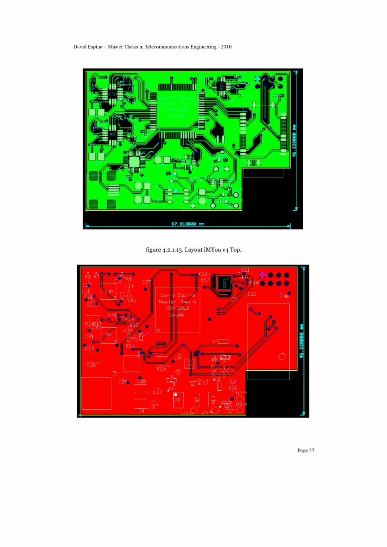
7/22/2019 Gyro With Avr
http://slidepdf.com/reader/full/gyro-with-avr 59/101
figure 4.2.1.13. Layout iMYou v4 Top.
David Espina - Master Thesis in Telecommunications Engineering - 2010
Page 57

7/22/2019 Gyro With Avr
http://slidepdf.com/reader/full/gyro-with-avr 60/101
figure 4.2.1.14. Layout iMYou v4 Bottom.
The board after manufacturing is shown in figure 4.2.1.15 and figure 4.2.1.16.
figure 4.2.1.15. iMYou v4 Front.
David Espina - Master Thesis in Telecommunications Engineering - 2010
Page 58

7/22/2019 Gyro With Avr
http://slidepdf.com/reader/full/gyro-with-avr 61/101
figure 4.2.1.16. iMYou v4 Back.
Problems after manufacturing iMYou v4:
• the FTDI sends commands to the ATmega128 during the boot loading but it doesn’t get the right
signals back and so, it can’t be programmed via USB-Serial communications.
• The VDD pin from the FTDI should be connected to VDD_USB.
• There was no JTAG sockets for the programming of the USB which was needed after the failure of
the USB-Serial communication
In the layout tool, the placement of the components was planned strategically to separate components
by usage and function. There are three differenced regions with a central core:
• power region
• programming
• sensors and bluetooth
• MCU in the middle
The power region is placed on the south west corner and starts with the USB mini on the corner. Is
followed by the battery charger, the low-drop voltage converter and the switch button. The switch pads
were bridged as a functional testing tool, avoiding using the battery and feeding from the USB.
The programming area starts with the data lines from the USB, serial resistors to the FTDI and ends
with the data lines from the FTDI to the ATmega128.
David Espina - Master Thesis in Telecommunications Engineering - 2010
Page 59

7/22/2019 Gyro With Avr
http://slidepdf.com/reader/full/gyro-with-avr 62/101
The rest of the board is organized with gyroscopes on the north west, MCU in the middle,
accelerometer between the MCU and the power area, bluetooth on the east part and the compass on the
north east area, as isolated as possible.
The inner layer 2 is a GND layer which is divided in two sub areas: digital and analog ground jointed
by a bridge. Those components that need an analog ground are the gyroscopes, and one specific pin
from the ATmega128, FTDI and compass. Due to this fact it was designed the placement of the
gyroscopes next to the FTDI on the north west corner, and close to the pin of the MCU which required
analog ground connection.
In the data sheet of the compass there is a restriction about the proper working of the device- No
copper can be placed on any of the layers under the device for it would affect the magnetic field and
give wrong lectures.
The shape of the board was designed to avoid the antenna of the bluetooth module, which was tested
by Martin Ekström on his bluetooth network research, resulting in a drop of directivity of almost 70%.
4.2.2.Hardware construction
After the manufacturing of every version of the board the components were mounted in the laboratory.
The iMYou v1 mounting process started with the smallest components which were the Rs and Cs 0402
size. The tools used to solder these components were a hand soldering pin, a microscope and a basic
soldering kit for SMD components. These tools were not effective for the kind of soldering that the
situation required and resulted on multiple burnt resistors and a dirty circuit board. It required a firm pulse and lots of flux fluid.
Right after the second manufacturing of the board, the errors were discovered and so, there was no
attempt to solder the components on the board.
During the manufacturing of the third board some hand soldering test took place to evaluate which
should be the best method to solder the components. There is a company called Microkit [45] at
Västerås Science park, which has some collaborations with MDH. They use an oven for small SMD
works with many components. In order to perform a good mounting there are two requirements to
place the components: a solder mask and solder paste.
The solder mask is a thin metallic sheet with holes with the shape of every pad that should be soldered.
The solder paste is a semi fluid solder which is easy to handle and place on the desired places and
melts over an specific temperature after an specific time, given by the vendor. It must be applied
uniformly over all the pads resulting in a thin layer. It must be kept in a cool place.
The performance of the oven took the following steps to keep the temperature high enough to solder
the components and a short amount of time, enough not to damage the components:
David Espina - Master Thesis in Telecommunications Engineering - 2010
Page 60

7/22/2019 Gyro With Avr
http://slidepdf.com/reader/full/gyro-with-avr 63/101
• placement of the solder paste
• placement of the components and alignment
• introducing the board in the oven and set the temperature to 160º for 3 minutes.• rise the temperature to 220º for 40 seconds
• turn off the oven and wait for the cooling
The test with iMYou v3 was without solder mask. The distribution of the solder paste was not uniform
and so it could not be guaranteed that the MLF components such as the MCU, inertial motion
components, FTDI and bluetooth module, had plat position and all their pins were connected to the
pads. Another inconvenient issue was the fact that checking connectivity under these components is
very difficult with a regular multimeter.
The most challenging task was to align the MLF shape of the ATmega128, since there was a design
error. The fact that there was a heat sink under this component helped to have a self alignment duringthe melting of the solder in the oven. This is caused by the properties of the solder paste which attract
metallic elements when is heated and so, as there is a symmetrical distribution of pads, there is a slight
attraction of the component towards the correct position if there is a small misalignment.
After the mounting in the oven a heat gun was used to correct those misalignments that the oven
couldn’t fix and also the solder pin was used to make sure every pin was properly soldered.
The mounting of the iMYou v4 was easier with the solder mask which resulted of big help to apply the
same amount of solder paste on the pads. The result was clean an very accurate. The ATmega128 MLF
was replaced by its TQFP package which was easier to place and correct with the solder pin.
The FTDI-MCU communication failed during the boot loading and different configurations of theVDD and VDDIO pins of the FTDI were tested. The correct one is VDD connected to VDD_USB and
VDDIO connected to VDD.
The last physical upgrade performed on the iMYou v4 was the addition of the JTAG interface for the
ATmega128, since the USB-Serial communication or the SPI interface for the programming didn’t
work. This upgraded consisted on four extra wires connected to ports PF4 to PF7 and another extra
wire connected to RESET. The JTAG interface used to program the board was the AVR JTAGICE
mkII [46] shown in figure 4.2.2.1.
David Espina - Master Thesis in Telecommunications Engineering - 2010
Page 61

7/22/2019 Gyro With Avr
http://slidepdf.com/reader/full/gyro-with-avr 64/101
figure 4.2.2.1. AVR JTAGICE mkII.
The last step in the hardware implementation is connecting the device to a source power (USB
preferable over battery) and test the voltage on each pin of every component. The section 5.Results
analysis explains with specific data the performance of these measures.
4.3.Software
This section describes the development of the iMYou system, which is the next step after the circuit
board is mounted and the voltage level on every pin is correct.
The pieces of software previous the correct functioning of the iMYou are divided in two groups of
requirements: requirements on the specific components of the circuit board, and requirements on the
PC.
There are different programming languages, tools and environments used and described in this section.Having serial communication as a common element, is easy to communicate between different
platforms and update tools with new environments and operative systems, plus there are several
testing tools which help to the development of the software and firmware.
4.3.1.Tools and environment
Once the USB is connected to the board and to the PC, the USB starts transmitting data to the FTDI
device and, as is explained in previous sections, the handshake is automatic and, if the proper drivers
for the FT232RQ are installed on the PC, the device will be automatically recognized as a serial
interface. The drivers are available in the download section of the FTDI website [28].
During the testing of the iMYou v3 and iMYou v4 functioning, there was the need of use a testing
tools from the FTDI website. This tool was FT_PROG.exe which offers a user interface to run simple
identification tools and change basic parameters on the FTDI (figure 4.3.1.1).
David Espina - Master Thesis in Telecommunications Engineering - 2010
Page 62

7/22/2019 Gyro With Avr
http://slidepdf.com/reader/full/gyro-with-avr 65/101
figure 4.3.1.1. FT_PROG.exe
This tools was useful to solve the voltage problems after the manufacturing of the iMYou v3. The USB
was plugged into the USB port of the PC and into the mini connector of the iMYou. There were 5 V
present on the VDD_USB line, FTDI VDD pin and FTDI VDDIO pin, but the device was not
recognized.
The data sheet of the FTDI indicated that the 3V3OUT pin should be connected to the VDDIO pin,
due to the specific set up. This didn’t solve the problem, since is presumable that the voltage at the
3V3OUT and the voltage at VDD where not exactly the same, which made a malfunction.
Another common error was that the USB ports of the PC failed several times. The power line from the
USB had the correct voltage, but the handshake was not taking place through the data lines.
After changing FTDI VDDIO pin to 3.3V VDD the FTDI chip started to send back the correct signals
to the USB and pop up as a new device ready to work (figure 4.3.1.2 and figure 4.3.1.3).
David Espina - Master Thesis in Telecommunications Engineering - 2010
Page 63

7/22/2019 Gyro With Avr
http://slidepdf.com/reader/full/gyro-with-avr 66/101
figure 4.3.1.2. USB handshake TX
figure 4.3.1.3. USB handshake RX
David Espina - Master Thesis in Telecommunications Engineering - 2010
Page 64

7/22/2019 Gyro With Avr
http://slidepdf.com/reader/full/gyro-with-avr 67/101
An alternative tools used to detect the FTDI chip was USB VIEW.exe which was not that effective as
FT_PROG.exe. This tools displays the USB ports in the PC, both physical and virtual, and shows
which kind of devices are plugged in (figure 4.3.1.4)
figure 4.3.1.4. USB VIEW
If the USB-FTDI is correct, the next step is checking the FTDI-MCU. There is no specific tool
available by any vendor to check this, so is necessary to implement one.
At MDH they have implemented a boot loader utility called boot_loader_init.exe implemented in
ADA [23]. There programming environment used for ADA was a version of GNAT Pro [47].
This boot loader opens the communications between the FTDI and the ATmega128, activates de
programming mode of the microcontroller and sets the necessary fuses configuration, registering in the
flash memory of the MCU. At this point is where the bit bang mode is working, by transforming the
packages from the USB into serial packages sent via UART to the MCU.
The boot loader first communicates with the FTDI asking for identification. If the FTDI is detected,then a command is sent to the ATmega128 to enable programming mode. This command is sent until
the MCU sends back the correct answer to continue the boot loading. The next step is read the
signature of the microcontroller which is a three pairs of hexadecimal values. After this, the actual
configuration of the fuses is read. The next step is to write in the registers the fuses configuration to
get the device ready to be programed via serial communication.
David Espina - Master Thesis in Telecommunications Engineering - 2010
Page 65
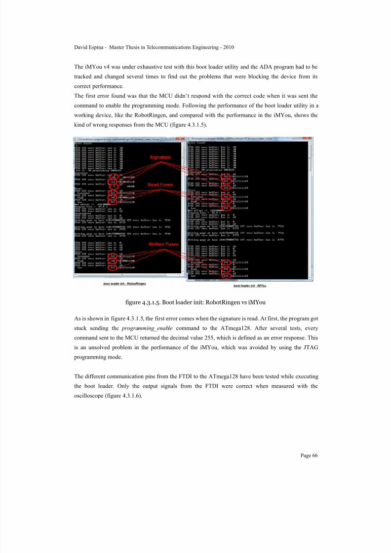
7/22/2019 Gyro With Avr
http://slidepdf.com/reader/full/gyro-with-avr 68/101
The iMYou v4 was under exhaustive test with this boot loader utility and the ADA program had to be
tracked and changed several times to find out the problems that were blocking the device from its
correct performance.
The first error found was that the MCU didn’t respond with the correct code when it was sent thecommand to enable the programming mode. Following the performance of the boot loader utility in a
working device, like the RobotRingen, and compared with the performance in the iMYou, shows the
kind of wrong responses from the MCU (figure 4.3.1.5).
figure 4.3.1.5. Boot loader init: RobotRingen vs iMYou
As is shown in figure 4.3.1.5, the first error comes when the signature is read. At first, the program got
stuck sending the programming_enable command to the ATmega128. After several tests, every
command sent to the MCU returned the decimal value 255, which is defined as an error response. This
is an unsolved problem in the performance of the iMYou, which was avoided by using the JTAG
programming mode.
The different communication pins from the FTDI to the ATmega128 have been tested while executing
the boot loader. Only the output signals from the FTDI were correct when measured with theoscilloscope (figure 4.3.1.6).
David Espina - Master Thesis in Telecommunications Engineering - 2010
Page 66
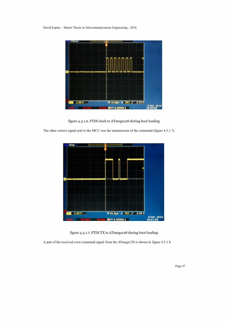
7/22/2019 Gyro With Avr
http://slidepdf.com/reader/full/gyro-with-avr 69/101
figure 4.3.1.6. FTDI clock to ATmega128 during boot loading
The other correct signal sent to the MCU was the transmission of the command (figure 4.3.1.7).
figure 4.3.1.7. FTDI TX to ATmega128 during boot loading
A part of the received error command signal from the ATmega128 is shown in figure 4.3.1.8
David Espina - Master Thesis in Telecommunications Engineering - 2010
Page 67
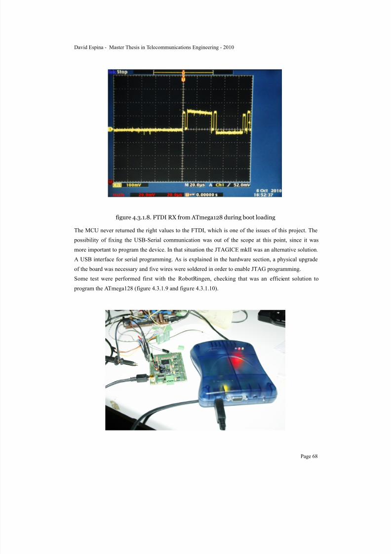
7/22/2019 Gyro With Avr
http://slidepdf.com/reader/full/gyro-with-avr 70/101
figure 4.3.1.8. FTDI RX from ATmega128 during boot loading
The MCU never returned the right values to the FTDI, which is one of the issues of this project. The
possibility of fixing the USB-Serial communication was out of the scope at this point, since it was
more important to program the device. In that situation the JTAGICE mkII was an alternative solution.
A USB interface for serial programming. As is explained in the hardware section, a physical upgrade
of the board was necessary and five wires were soldered in order to enable JTAG programming.
Some test were performed first with the RobotRingen, checking that was an efficient solution to
program the ATmega128 (figure 4.3.1.9 and figure 4.3.1.10).
David Espina - Master Thesis in Telecommunications Engineering - 2010
Page 68

7/22/2019 Gyro With Avr
http://slidepdf.com/reader/full/gyro-with-avr 71/101
figure 4.3.1.9. RobotRingen JTAG programming
figure 4.3.1.10. RobotRingen JTAG pin configuration.
The connection to the JTAG was through the bulky JTAG connector (figure 4.3.1.11). The pin
configuration is specified in the table 4.3.1.1.
figure 4.3.1.11. JTAG bulky connector.
Pin Color Name iMYou pin
1 black TCK PF7
2 white GND GND
3 gray TDO PF5
David Espina - Master Thesis in Telecommunications Engineering - 2010
Page 69

7/22/2019 Gyro With Avr
http://slidepdf.com/reader/full/gyro-with-avr 72/101
Pin Color Name iMYou pin
4 purple VTref VDD
5 blue TMS PF6
6 green nSRST RESET
7 yellow Vsupply n/a
8 orange nTRST n/a
9 red TDI PF4
10 brown brown n/a
table 4.3.1.1. JTAG pin connections
The JTAG connexion both the RobotRingen and the iMYou was successful and the communication
with the programming environment was correct. The software used to program the devices was AVR
Studio [24] which has a JTAG tool to easily transfer the program into the memory of the
microcontroller. During the communication via JTAG, measurements of the signals where taken to
confirm that both devices were performing in the same way (figure 4.3.1.12, figure 4.3.1.13 and figure
4.3.1.14).
figure 4.3.1.12. JTAG TX, data line
David Espina - Master Thesis in Telecommunications Engineering - 2010
Page 70
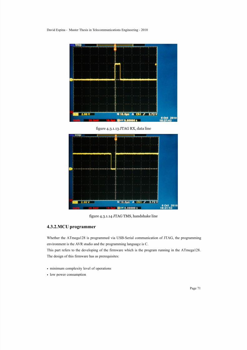
7/22/2019 Gyro With Avr
http://slidepdf.com/reader/full/gyro-with-avr 73/101
figure 4.3.1.13 JTAG RX, data line
figure 4.3.1.14 JTAG TMS, handshake line
4.3.2.MCU programmer
Whether the ATmega128 is programmed via USB-Serial communication of JTAG, the programming
environment is the AVR studio and the programming language is C.This part refers to the developing of the firmware which is the program running in the ATmega128.
The design of this firmware has as prerequisites:
• minimum complexity level of operations
• low power consumption
David Espina - Master Thesis in Telecommunications Engineering - 2010
Page 71
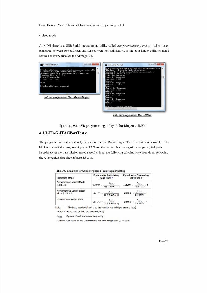
7/22/2019 Gyro With Avr
http://slidepdf.com/reader/full/gyro-with-avr 74/101
• sleep mode
At MDH there is a USB-Serial programming utility called avr_programmer_16m.exe which tests
compared between RobotRingen and iMYou were not satisfactory, as the boot loader utility couldn’tset the necessary fuses on the ATmega128.
figure 4.3.2.1. AVR programming utility: RobotRingen vs iMYou
4.3.3.JTAG JTAGPortTest.c
The programming test could only be checked at the RobotRingen. The first test was a simple LED
blinker to check the programming via JTAG and the correct functioning of the output digital ports.
In order to set the transmission speed specifications, the following calculus have been done, followingthe ATmega128 data sheet (figure 4.3.2.1).
David Espina - Master Thesis in Telecommunications Engineering - 2010
Page 72
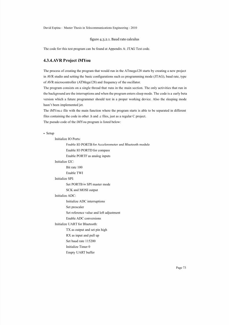
7/22/2019 Gyro With Avr
http://slidepdf.com/reader/full/gyro-with-avr 75/101
figure 4.3.2.1. Baud rate calculus
The code for this test program can be found at Appendix A: JTAG Test code.
4.3.4.AVR Project iMYou
The process of creating the program that would run in the ATmega128 starts by creating a new project
in AVR studio and setting the basic configurations such as programming mode (JTAG), baud rate, type
of AVR microcontroller (ATMega128) and frequency of the oscillator.
The program consists on a single thread that runs in the main section. The only activities that run in
the background are the interruptions and when the program enters sleep mode. The code is a early beta
version which a future programmer should test in a proper working device. Also the sleeping mode
hasn’t been implemented jet.
The iMYou.c file with the main function where the program starts is able to be separated in different
files containing the code in other .h and .c files, just as a regular C project.
The pseudo code of the iMYou program is listed below:
• Setup
Initialize IO Ports:
Enable IO PORTB for Accelerometer and Bluetooth module
Enable IO PORTD for compass
Enable PORTF as analog inputs
Initialize I2C:
Bit rate 100
Enable TWI
Initialize SPI:
Set PORTB in SPI master mode
SCK and MOSI output
Initialize ADC:
Initialize ADC interruptions
Set prescaler
Set reference value and left adjustment
Enable ADC conversions
Initialize UART for Bluetooth:
TX as output and set pin high
RX as input and pull up
Set baud rate 115200
Initialize Timer 0
Empty UART buffer
David Espina - Master Thesis in Telecommunications Engineering - 2010
Page 73

7/22/2019 Gyro With Avr
http://slidepdf.com/reader/full/gyro-with-avr 76/101
Turn off UART RX for bluetooth
LOOP
• Read SensorsRead Compass
Read X at address 0x03
Read Y at address 0x05
Read Z at address 0x07
Read Accelerometer
Read X at address 0b11101000
Read Y at address 0b11101010
Read Z at address 0b11101100
Read ADC raw data
LOOP Read new data and write into ADC buffers
UNTIL all buffers are filled
Initialize next reading
Read Gyro XY
X value to buffer[1]
Y value to buffer[2]
VRef value to buffer [3]
Read Gyro YZ
X value to buffer[4]
Y value to buffer[5] VRef value to buffer [6]
• Send data
Pack data to send with iNemo package protocol
*Bluetooth to be implemented
GOTO LOOP
The code for the iMYou firmware can be found at Appendix B: AVR iMYou Project.
4.3.5.Compatibility with iNemo
The data gathered from the sensors must be packed and sent via Bluetooth according with iNemo GUI
protocol (figure 4.3.5.1).
David Espina - Master Thesis in Telecommunications Engineering - 2010
Page 74
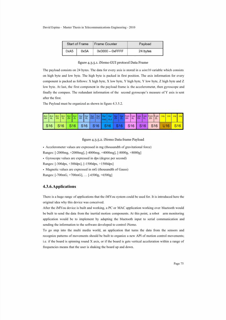
7/22/2019 Gyro With Avr
http://slidepdf.com/reader/full/gyro-with-avr 77/101
figure 4.3.5.1. iNemo GUI protocol Data Frame
The payload consists on 24 bytes. The data for every axis is stored in a uint16 variable which consists
on high byte and low byte. The high byte is packed in first position. The axis information for every
component is packed as follows: X high byte, X low byte, Y high byte, Y low byte, Z high byte and Z
low byte. At last, the first component in the payload frame is the accelerometer, then gyroscope and
finally the compass. The redundant information of the second gyroscope’s measure of Y axis is sent
after the first.
The Payload must be organized as shown in figure 4.3.5.2.
AccXH
AccXL
AccYH
AccYL
AccZH
AccZL
GyrXH
GyrXL
GyrYH1
GyrYL1
Gyr
YH2
Gyr
YL2
GyrZH
GyrZL
ComXH
omXL
omYH
omYL
ComZH
omZL
n/a n/a n/a n/a
S16 S16 S16 S16 S16 S16 S16 S16 S16 S16 U16 S16
figure 4.3.5.2. iNemo Data frame Payload
• Accelerometer values are expressed in mg (thousandth of gravitational force)
Ranges: [-2000mg, +2000mg], [-4000mg, +4000mg], [-8000g, +8000g]
• Gyroscope values are expressed in dps (degree per second)
Ranges: [-300dps, +300dps], [-1500dps, +1500dps]
• Magnetic values are expressed in mG (thousandth of Gauss)
Ranges: [-700mG, +700mG], … [-6500g, +6500g]
4.3.6.Applications
There is a huge range of applications that the iMYou system could be used for. It is introduced here the
original idea why this device was conceived.
After the iMYou device is built and working, a PC or MAC application working over bluetooth would
be built to send the data from the inertial motion components. At this point, a robot arm monitoring
application would be to implement by adapting the bluetooth input to serial communication and
sending the information to the software developed to control iNemo.
To go step into the multi media world, an application that turns the data from the sensors and
recognize patterns of movements should be built to organize a new API of motion control movements;
i.e. if the board is spinning round X axis, or if the board is gets vertical acceleration within a range of
frequencies means that the user is shaking the board up and down.
David Espina - Master Thesis in Telecommunications Engineering - 2010
Page 75

7/22/2019 Gyro With Avr
http://slidepdf.com/reader/full/gyro-with-avr 78/101
With this API built, there could be a development of an interface to interact with a sequencer of a
synthesizer to launch sounds, such as Native Instruments Kontakt 4 [48]. This could be an application
to create music by specific dancing movements. To monitor this actions and interact with the program
as the user is dancing, an iPhone or Android app could be developed which would communicate viawi-fi with the PC or MAC. There is an adapter for iPhone that permits plug a pair of goggles with
screens in the lenses which would make the interaction easier and an spectacular display if the dancer
is in a performance [49].
5.Conclusions
The design and development of the iMYou hasn’t followed strict implementation rules such as the
standard planning process for the design flow and implementation of FPGA or ASIC. At the same
time, the requirements for the implementation of a device that could be a market target was focused on
building a small and compact design without a prototype. These are two fundamental errors which bring many others with them.
The planning of such a project should include a team of three or four people. All together should
discuss the strategy to follow and gather the requirements to fulfill the necessities of
such a project. There should be different roles such as hardware design, layout design, mounting,
software design, and software implementation. Each one of these named roles is a field of expertise
that involves a deep knowledge to avoid conflicts and learning by trying.
This project has had a complete focus on hardware design and implementation, which was a different
idea from what it was conceived from start. During the design of the circuit board there has been
several knowledge achievements such as specification of the QFN components with a heat sink,
temperature before melting, long exposure to heat, width of the annular rings to avoid currents spreadin undesirable directions, structure of the copper under magnetic field measurement components,
analog and digital reference and its current distribution, communication standards and protocols such
as UART, SPI, I2C and Bluetooth, ADA, Objective-C and iphone programming.
Nevertheless, this deep study and research on the physical implementation of a circuit board and its
firmware has given the opportunity to get a more expert approach on this field of knowledge.
The most recent telecommunication technologies require new personal who can cover these needs, be
able to build new devices, give support to the last specifications and know the theory; for example,
mobile communications, 3G/LTE and 4G.
6.Future Work
If a student at MDH would continue with this project there could be two approaches: hardware or
software.
David Espina - Master Thesis in Telecommunications Engineering - 2010
Page 76

7/22/2019 Gyro With Avr
http://slidepdf.com/reader/full/gyro-with-avr 79/101
The hardware approach implies to redesign from scratch and add those missing features that would
help to test the iMYou. The most important suggestion is that the sizes of the components are changed
to a bigger package of the Rs and Cs; 0805 for instance. It is also highly recommended to change the
package of the FTDI and use the FT2323RL. When redesigning the circuit board use as bigdimensions as necessary and try to design the pads in that manner that requires the minimum use of
vias. So that, the board could be prototyped and manufactured at the university with the PCB
prototype machine, which would imply only 2 layers circuit board.
Another feature to include is a JTAG socket for the MCU which is missing in iMYou v4 (figure 6.1).
figure 6.1. iMYou v4 3D model
A totally different hardware implementation would be to build three different boards: one for bluetooth
communication, another for the inertial motion components and the other one holding the MCU and
rest of elements. These boards should have link ports to communicate between each other.
A software approach would imply to finish the iMYou firmware: package the data as explained in
section 4.3.5.Compatibility with iNemo, implement the bluetooth commands and transition states to
build a proper bluetooth connection. Then, an interface supporting bluetooth and the iNemo Data
Frame should be implemented in PC or MAC.
Before such a complex implementation, it would test the bluetooth connexion with the tools available
at the lab. The following proposed configuration requires only to implement firmware for bluetooth
support by previously reading the documentation of the BlueTool; a testing software for PC that
allows to send and receive all the standard commands over bluetooth.
The components needed are listed below:
David Espina - Master Thesis in Telecommunications Engineering - 2010
Page 77
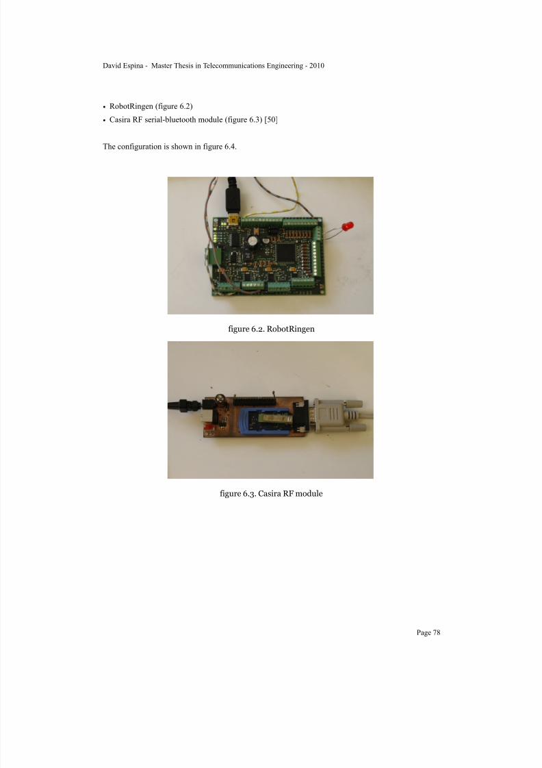
7/22/2019 Gyro With Avr
http://slidepdf.com/reader/full/gyro-with-avr 80/101
• RobotRingen (figure 6.2)
• Casira RF serial-bluetooth module (figure 6.3) [50]
The configuration is shown in figure 6.4.
figure 6.2. RobotRingen
figure 6.3. Casira RF module
David Espina - Master Thesis in Telecommunications Engineering - 2010
Page 78

7/22/2019 Gyro With Avr
http://slidepdf.com/reader/full/gyro-with-avr 81/101
figure 6.4. RobotRingen over bluetooth
David Espina - Master Thesis in Telecommunications Engineering - 2010
Page 79

7/22/2019 Gyro With Avr
http://slidepdf.com/reader/full/gyro-with-avr 82/101
7.References
1. Hot Hand® Wah, Source Audio , 2008, www.sourceaudio.net/products/hothand/wah.php
2. Paul L. DiMatteo, New York, 24 feb 1976, Navigational error correcting system, USA
patent 3940597, http://www.freepatentsonline.com/3940597.pdf
3. Victor Auerbach, New Jersey, 16 Nov. 1976, Error Canceling scanning optical angle measurement
system, patent 3992106, optical
4. Theodore Mairson, Lexington, Mass. 16 Sep 1980, Processor for an inertial measurement unit ,
patent 4222272, http://www.freepatentsonline.com/4222272.pdf
5. John W. Smay, Torrance, California, 13 Mar 1984, System for autonomous earth-pointing
acquisition of a dual-spin satellite, patent 4437047 http://www.freepatentsonline.com/4437047.pdf
6. Jeffrey T. Smith, Redmond Washington, 14 JUN 1984, Inertial Reference system, patent 4675820,
http://www.freepatentsonline.com/4675820.pdf
7. Shing P. Kau , Seminole Fla., 19 Nov. 1991, Inertial measurement unit with aiding from roll
isolated gyro. patent 5067084.
8. Rogers R.M., Palm Springs, CA., 23 Arp. 1998, Low dynamic IMU alignment., from Position
Location and Navigation Symposium, IEEE 1998, ISBN 0-7803-4330-1
9. Michael Barr, 21 May 2007, Embedded Systems Glossary, Netrino Technical Library, http://
www.netrino.com/Embedded-Systems/Glossary
10.Jens Eliasson, Luleå University of Technology, 2008, Low-Power design methodology for
embedded internet Systems, Doctoral Thesis, ISSN:1402-1544 ISRN: LTU-DT--08/13--SE
11.ONI-23505 OEM Digital Module, O-Navi™. http://www.o-navi.com/FalconGX_4.pdf
12.STEVAL-MKI062V1, iNemo STMicroelectronics, 2008, http://www.st.com/stonline/products/
families/evaluation_boards/steval-mki062v1.htm.
13.BTNode, ETH Zurich 2008, http://www.btnode.ethz.ch/
14.iMote,Lama Nachman, Corporate Technology Group & Intel Corporation, 2005, THE INTEL®
MOTE PLATFORM: A BLUETOOTH*-BASED SENSOR NETWORK FOR INDUSTRIAL
MONITORING, 0-7803-9201-9/05/$20.00 ©2005 IEEE
15.Mulle, Luleå Tekniska Universitet, 2006, http://www.ltu.se/csee/research/eislab/areas/mixedmode/
projects/mulle
16.BT-IMU Bluetooth inertial measurement unit, Omni Instruments, 2009, http://www.omniinstruments.co.uk/products/product/moredetails/bt-imu.id658.html
17.6DOF IMU 6 degrees of freedom, Sparkfun Electronics, 2010, http://www.sparkfun.com/
commerce/product_info.php?products_id=8454
David Espina - Master Thesis in Telecommunications Engineering - 2010
Page 80

7/22/2019 Gyro With Avr
http://slidepdf.com/reader/full/gyro-with-avr 83/101
18.DJammer 2004. Hewlett-Packard. http://www.hpl.hp.com/research/mmsl/projects/djammer/
index.html
19.ABB robotics, 2010, www.abb.com/robotics.
20.Västerås Science Park, 2010, http://vasterassciencepark.se/
21.ATmega128 data sheet, Atmel Corporation, 2009, http://www.atmel.com/dyn/products/
product_card.asp?part_id=2018.
22.Martin Ekström, Doctoral Research at IDT Mälardalen University, 2010. Development and
implementation of Power Efficient Wireless Intelligent Technology for Wireless Sensors Network ,
http://www.mrtc.mdh.se/han/FoPlan/ass2-MartinE.pdf
23.ADA programming language, 2010, http://www.adahome.com/
24.AVR Studio, programming environment for Atmel micro controllers, http://www.atmel.com/dyn/
products/tools_card.asp?tool_id=2725
25.WinAVR, programming environment for Atmel micro controllers, http://winavr.sourceforge.net/.
26.AVR JTAG mkII, AVR development tools 2010, http://www.atmel.com/dyn/products/
tools_card.asp?tool_id=3353
27.USB mini connector, data sheet, 2008, http://www.hirose.co.jp/cataloge_hp/e24000019.pdf
28.FTDI FT232R, data sheet, 2008, http://www.ftdichip.com/Support/Documents/DataSheets/ICs/
DS_FT232R.pdf
29.Ahmer Syed and WonJoon Kang, Amkor Technology, Inc., 2010, Chandler Arizona, Board Level
Assembly and reliability considerations for QFN type packages, http://www.amkor.com/index.cfm?
objectid=CB884AAF-F282-69C7-E4075D053DCE11D7
30.SSOP package, Amkor Technologies, 2010, http://www.amkor.com/go/packaging/all-packages/
ssop/ssop
31.CS-XEW01SL, Lithium Battery, 2010, http://www.batteryupgrade.com/shopBrowser.php?
assortmentProductId=39273095#/assortmentProductId/39273095/shopGroupId
32.Battery Performance Characteristics, Electropedia, 2005, http://www.mpoweruk.com/
performance.htm
33.Battery Charger, Max1811, MAXIM, 2010, http://www.maxim-ic.com/datasheet/index.mvp/id/
2536
34.ATMEL, 2010, http://www.atmel.com
35.AVR micro controllers, 2010, http://www.atmel.com/products/AVR/
36.HCI UART Transport Layer (H4), BlueCore™, CSR, July 2004, Cambridge Science Park,
Cambridge, United Kingdom, Registered in England 3665875, bcore-sp-010Pb.
David Espina - Master Thesis in Telecommunications Engineering - 2010
Page 81

7/22/2019 Gyro With Avr
http://slidepdf.com/reader/full/gyro-with-avr 84/101
37.USB Data Packet Structure Version 1.0 Clearance No.: FTDI# 128, Document Reference No.:
FT_000200, FTDI, 2009, http://www.ftdichip.com/Support/Documents/TechnicalNotes/
TN_116_USB%20Data%20Structure.pdf
38.Microcontroller UART Tutorial, Society of Robots, 2010, www.societyofrobots.com/
microcontroller_uart.shtml
39.FT232 Bit-bang mode, FTDI, 2002, http://www.ftdichip.com/Support/Documents/AppNotes/
AN232B-01_BitBang.pdf
40.Overview and use of the PICmicro Serial Peripheral Interface, Microchip, http://
ww1.microchip.com/downloads/en/devicedoc/spi.pdf
41.I2C Background, Knowledge Base 10037, Total Phase, 2010, http://www.totalphase.com/support/
kb/10037/
42.Analog to digital converter, ATmega128 data sheet p.230, Atmel Corporation ©, 2009, http://
www.atmel.com/dyn/products/product_card.asp?part_id=2018.
43.Multisim, National Instruments, 2010, http://www.ni.com/multisim/
44.Ultiboard, National Instruments, 2010, http://www.ni.com/ultiboard/
45.Micro-Kit Elektronik AB, Västerås Science Park, 2010, http://www.microkit.se/.
46.AVR JTAGICE mkII, Atmel. 2010, http://www.atmel.com/dyn/Products/tools_card.asp?
tool_id=3353
47.GNAT Pro, ADA programming environment, 2010, http://www.adacore.com/home/products/
gnatpro/?gclid=CJLN0tiR16QCFceR3wodoUooKA
48.Kontakt 4, Native Instruments, 2010, http://www.native-instruments.com/#/en/products/producer/
kontakt-4/
49.iWear AV230 XL+, Vuzix, 2010, http://www.vuzix.com/consumer/products_av230xl.html
50.Casira RF module, Cambridge Silicon Radio Ltd., UK, 2010, http://
www.cambridgesilliconradio.com
David Espina - Master Thesis in Telecommunications Engineering - 2010
Page 82

7/22/2019 Gyro With Avr
http://slidepdf.com/reader/full/gyro-with-avr 85/101
Appendix A: JTAG Test codeProject Files
JTagTest.c
JTAGPortTest.c//*****************************************************************************// File Name : JTagTest.c//// Title : JTagTest// Revision : 1.0// Notes : // Target MCU : Atmel AVR series// Editor Tabs ://// Revision History:// When Who Description of change// ----------- ----------- -----------------------// 10-Sep-2010 David Espina Created the program//*****************************************************************************/*// CPU clock speed * System clock in Hz. */#define F_CPU 16000000UL // 16MHz processor#define CYCLES_PER_US ((F_CPU+500000)/1000000) // cpu cycles per microsecond
//----- Include Files ---------------------------------------------------------#include <avr/io.h> // include AVR I/O definitions (port names, pin names, etc)#include <avr/interrupt.h> // include AVR interrupt support#include <util/delay.h>#include <inttypes.h>#include <stdio.h>#include <stdlib.h>
//Function definitions//=-=-=-=-=-=-=-=-=-=-=-=-=-=-=-=-=-=-=-=-=-=-=-=-=-=-=void delay_ms(uint16_t x);void delay_us(uint16_t x);
//------function headers ------------------------------------------------------int setPortBitState(char port,int position, int value);void ioinit(void);void testCode(void);
//*********************************//****** MAIN//*********************************//----- Begin Code ------------------------------------------------------------
int main(void){ //comment this line when not using under TEST testCode(); return 1;}
int setPortBitState(char port,int position, int value){ // Sets or clears the bit in position 'position'
// either high or low (1 or 0) to match 'value'. // Leaves all other bits in PORTB unchanged. switch(port) {
case 'A':if (value == 0)
{ PORTA &= ~(1 << position); // Set bit position low } else { PORTA |= (1 << position); // Set high, leave others alone } return 1;
case 'B':if (value == 0)
{ PORTB &= ~(1 << position); // Set bit position low } else { PORTB |= (1 << position); // Set high, leave others alone } return 1;
David Espina - Master Thesis in Telecommunications Engineering - 2010
Page 83
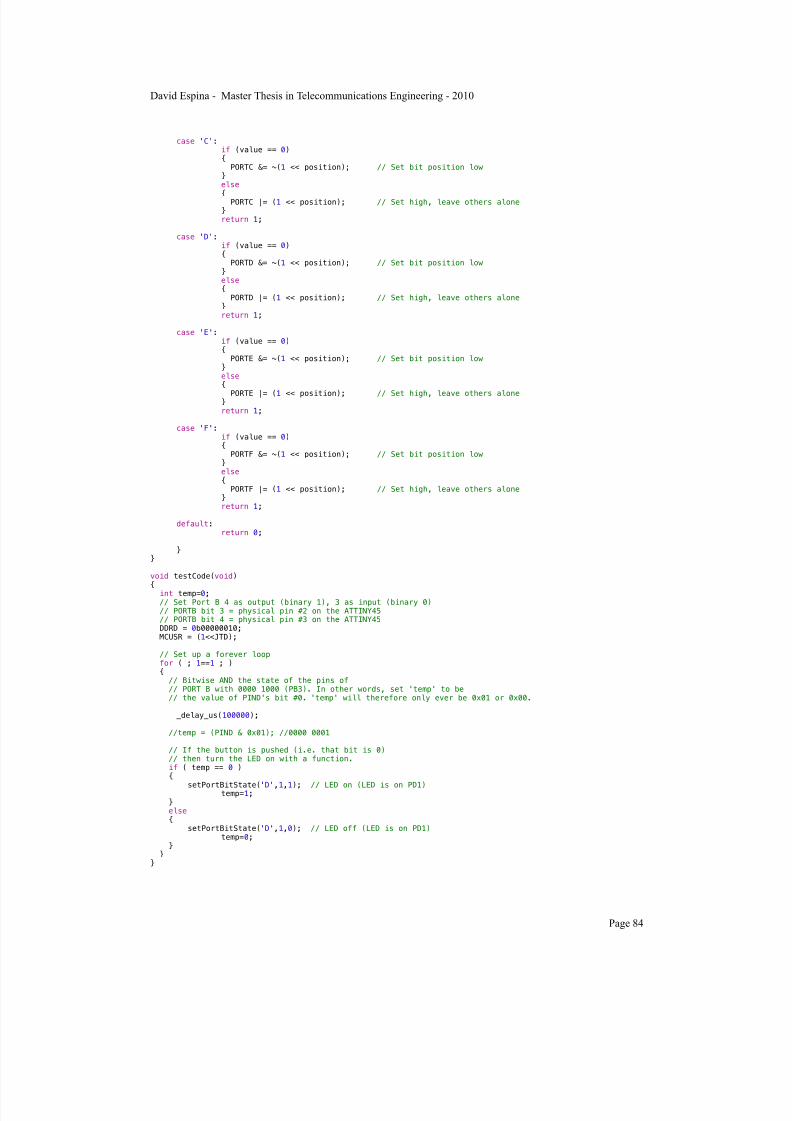
7/22/2019 Gyro With Avr
http://slidepdf.com/reader/full/gyro-with-avr 86/101
case 'C':if (value == 0)
{ PORTC &= ~(1 << position); // Set bit position low } else
{ PORTC |= (1 << position); // Set high, leave others alone } return 1;
case 'D':if (value == 0)
{ PORTD &= ~(1 << position); // Set bit position low } else { PORTD |= (1 << position); // Set high, leave others alone } return 1;
case 'E':if (value == 0)
{ PORTE &= ~(1 << position); // Set bit position low } else {
PORTE |= (1 << position); // Set high, leave others alone } return 1;
case 'F':if (value == 0)
{ PORTF &= ~(1 << position); // Set bit position low } else { PORTF |= (1 << position); // Set high, leave others alone } return 1;
default: return 0;
}}
void testCode(void){ int temp=0; // Set Port B 4 as output (binary 1), 3 as input (binary 0) // PORTB bit 3 = physical pin #2 on the ATTINY45 // PORTB bit 4 = physical pin #3 on the ATTINY45 DDRD = 0b00000010; MCUSR = (1<<JTD);
// Set up a forever loop for ( ; 1==1 ; ) { // Bitwise AND the state of the pins of // PORT B with 0000 1000 (PB3). In other words, set 'temp' to be
// the value of PIND's bit #0. 'temp' will therefore only ever be 0x01 or 0x00. _delay_us(100000);
//temp = (PIND & 0x01); //0000 0001
// If the button is pushed (i.e. that bit is 0)// then turn the LED on with a function.
if ( temp == 0 ) {
setPortBitState('D',1,1); // LED on (LED is on PD1) temp=1; } else { setPortBitState('D',1,0); // LED off (LED is on PD1) temp=0; } }}
David Espina - Master Thesis in Telecommunications Engineering - 2010
Page 84

7/22/2019 Gyro With Avr
http://slidepdf.com/reader/full/gyro-with-avr 87/101
Appendix B: AVR iMYou Project
Project Files
iMYou.c
constants.h
i2c.h
SPI\spi.h
SPI\spi.c
ADC\adc.h
ADC\adc.c
sw UART\sw_uart.h
sw UART\sw_uart.c
iMYou.c//*****************************************************************************// File Name : iMYou.c//// Title : iMYou// Revision : 1.0// Notes : // Target MCU : Atmel AVR series// Editor Tabs ://// Revision History:// When Who Description of change// ----------- ----------- -----------------------// 10-May-2010 David Espina Created the program//*****************************************************************************
//----- Include Files ---------------------------------------------------------#include "constants.h"#include <avr/io.h> // include AVR I/O definitions (port names, pin names, etc)#include <avr/interrupt.h> // include AVR interrupt support#include <util/delay.h>#include <inttypes.h>
#include <stdio.h>#include <stdlib.h>#include "i2c.h" //Needed for I2C sensors: Compass#include "SPI\spi.h" //needed for SPI sensors: Accelerometer#include "ADC\adc.h" //needed for Analog sensors: Gyroscopes#include "sw UART\sw_uart.h" //needed for BLuetooth under UART
//Function definitions//=-=-=-=-=-=-=-=-=-=-=-=-=-=-=-=-=-=-=-=-=-=-=-=-=-=-=void setup (void);void ioinit (void);int16_t read_hmc5843 (char reg_adr);void init_hmc5843 (void);void adc_init(void);void initializePorts (void);int setPortBitState (char port,int position, int value);void testCode (void);void readSensors (void);void sendData (void);void readCompass (void);void readAccel (void);void readGyroXY (void);
void readGyroYZ (void);void Analog_Reference(uint8_t mode);ISR(ADC_vect);void Read_adc_raw(void);void packDataToSend(void);
//=-=-=-=-=-=-=-=-=-=-=-=-=-=-=-=-=-=-=-=-=-=-=-=-=-=-=//Global variables//=-=-=-=-=-=-=-=-=-=-=-=-=-=-=-=-=-=-=-=-=-=-=-=-=-=-=//static FILE mystdout = FDEV_SETUP_STREAM(uart_putchar, NULL, _FDEV_SETUP_WRITE);static int16_t Xcompass, Ycompass, Zcompass;static int16_t Xaccel, Yaccel, Zaccel;
David Espina - Master Thesis in Telecommunications Engineering - 2010
Page 85

7/22/2019 Gyro With Avr
http://slidepdf.com/reader/full/gyro-with-avr 88/101
static int16_t XgyroXY, YgyroXY, VRefgyroXY;static int16_t XgyroYZ, YgyroYZ, VRefgyroYZ;
//ADC variablesvolatile uint8_t MuxSel=0;volatile uint8_t analog_reference = DEFAULT;volatile uint16_t analog_buffer[8];
volatile uint8_t analog_count[8];
float AN[9]; //array that store the 3 ADC filtered dataint8_t sensors[6] = {1,2,0,1,2,0}; // Map the ADC channels gyro_x, gyro_y, gyro_z//int SENSOR_SIGN[9] = {-1,1,-1,1,1,1,-1,-1,-1}; //Correct directions x,y,z - gyros, accels, magnetormeter
//***************************************************************************************************//***************************************************************************************************//***** **************************************************************************************//***** MAIN **************************************************************************************//***** **************************************************************************************//***************************************************************************************************//***************************************************************************************************
//----- Begin Code ------------------------------------------------------------int main(void){ setup(); //init components and BlueTooth Com //if BT com is not running won't go to the next step while(1) { readSensors(); //keeps in variables the data from the Sensors sendData(); //sends the data over BT
} return 1;}
/*MCU ATMEGA128 list of pins used and required configuration
RESET #DCD (FTDI)XTAL2 16MHz XTAL1 16MHz PB0 (SS) SPI_CS(BT) & CS(Accel) Output software ManagingPB1 (SCK) RI(FTDI) & SCL (Accel) & SPI_CLK(BT) Output software ManagingPB2 (MOSI) SDA (Accel) & SPI_MISO(BT) Output software Managing SPI MSTR INPUTPB3 (MISO) SCO (Accel) & SPI_MOSI(BT) Input software Managing SPI MSTR OUTPUTPB4 (OC0) LED Output PB5 (OC1A) KILL(Button CTRL) OutputPB6 (OC1B) INT (Button CTRL) InputPB7 *NC*
PD0 (SCL /INT0) SCL (Compass) Output Activate Bit 2 in TWRCPD1 (SDA /INT1) SDA (Compass) Output Activate Bit 2 in TWRCPD2 (RXD1/INT2) UART_TX (BT) Output Manage by softwarePD3 (TXD1/INT3) UART_RX (BT) Input Manage by softwarePD4 (ICP1) UART_CTS(BT) Output Manage by softwarePD5 (XCK1) UART_RTS(BT) Output Manage by softwarePD6 (T1) *NC*PD7 (T2) DRDY(Compass) Input
PE0 RXD0/(PDI) TX (FTDI)PE1 (TXD0/ PDO) RX (FTDI)PE2 (XCK0/AIN0) *NC*PE3 (OC3A/AIN1) *NC*PE4 (OC3B/INT4) *NC*PE5 (OC3C/INT5) *NC*PE6 (T3/INT6) *NC*PE7 (ICP3/INT7) *NC*
PF0 (ADC0) *NC*PF1 (ADC1) HP (Gyro U8 & U12) Digital Output (Gyro Reset)PF2 (ADC2) VREF(Gyro U8) AD Input - Set A/D ON bitPF3 (ADC3) 4xOUTY (Gyro U8) AD Input - Set A/D ON bitPF4 (ADC4/TCK) 4xOUTX (Gyro U8) AD Input - Set A/D ON bitPF5 (ADC5/TMS) VREF(Gyro U12) AD Input - Set A/D ON bitPF6 (ADC6/TDO) 4xOUTY (Gyro U12) AD Input - Set A/D ON bit
PF7 (ADC7/TDI) 4xOUTX (Gyro U12) AD Input - Set A/D ON bit
PG0 (WR) RTS (FTDI)PG1 (RD) CTS (FTDI)PG2 (ALE) DTR (FTDI)PG3 TOSC2 DSR (FTDI)PG4 TOSC1 *NC*
*/
//*********************************//****** Functions
David Espina - Master Thesis in Telecommunications Engineering - 2010
Page 86

7/22/2019 Gyro With Avr
http://slidepdf.com/reader/full/gyro-with-avr 89/101
//*********************************
void setup (void){ //port inizialization initializePorts(); ioinit(); //Boot up defaults
i2cInit();
//set the I2C bus ready spi_init(); //set SPI bus ready for Accel adc_init(); //set the A/D for the Gyros sw_uart_init(); //set UART port for BTlueTooth sw_uart_io_init(); //set UART port for BTlueTooth flush_input_buffer(); //buffer for UART flushed softuart_turn_rx_off(); //BT RX desactivated
}
void initializePorts (void){ //Activate SPI master mode
//SPI MSTR INPUT //Set PORTB - as SPI of BT y Accel, Push Button CTRL ,LED output //to read use PIND DDRB = 0b00111011; //Set SCL SDA : Two Wired serical Interface ON : TWCR Bit 2 TWEN: TWI Enable Bit TWCR |= (1 << 2);//Set PD7 - DRDY(Compass) as Input to read DRDY (data ready) //to read use PIND DDRD = 0b00110111;
PORTD = 0b00000011; //Gyro PortF A/D //Set PORT F 1 as digital output = RESET Gyro //Set PORT F 2,3,4,5,6,7 as analog inputs //to read use PINF DDRF = 0b00000010; //Set A/D Converter Enabled from ADCSRA register (bit 7 = 1) ADCSRA |= (1 << 7);
}
void ioinit(void){ //1 = output, 0 = input
DDRB = 0b11111111; DDRC = 0b11111111; DDRD = 0b11111111;
PORTD = 0b00000011; //pullups on the I2C bus //Setup USART baud rate
UBRR0H = SERIAL_MYUBRR >> 8; UBRR0L = SERIAL_MYUBRR; UCSR0B = (1<<RXEN0)|(1<<TXEN0); //No receive interrupt UCSR0A ^= (1<<U2X0); //This clears the double speed UART transmission that may be set by the Arduinobootloader
//stdout = &mystdout; //Required for printf init
//Init Timer0 for delay_us *Data sheet: pag.106 pag.363 TCCR0 = (1<<CS01); //Set Prescaler to clk/8 : 1click = 0.5us(assume we are running at external16MHz). CS01=1}
//Setup HMC5843 for constant measurement modevoid init_hmc5843(void){ _delay_us(5000); //required after power-on 5V enable
i2cSendStart(); i2cWaitForComplete();
i2cSendByte(HMC5843_W); //write to the HMC5843 i2cWaitForComplete();
i2cSendByte(0x02); //Write to Mode register i2cWaitForComplete();
i2cSendByte(0x00); //Clear bit 1, the MD1 bit i2cWaitForComplete();
i2cSendStop();}
// Initializes ADC (1/500) / 4 = 2khzvoid adc_init() {
David Espina - Master Thesis in Telecommunications Engineering - 2010
Page 87

7/22/2019 Gyro With Avr
http://slidepdf.com/reader/full/gyro-with-avr 90/101
//initialize interruptions ADCSRA|=(1<<ADIE)|(1<<ADEN); ADCSRA|= (1<<ADSC);
Analog_Reference(DEFAULT);
ADCSR &= ~_BV(ADEN); // disable adc before setup
//ADMUX &= ~(_BV(REFS0) | _BV(REFS1) | _BV(ADLAR)); // set to external AREF, right adjusted res ADMUX |= (_BV(ADLAR) | _BV(REFS0) | _BV(REFS1)); // left adjust result, 2.56vref
ADCSR |= _BV(ADIE); // enable adc interrupt
// prescaler 8 //ADCSR &= ~_BV(ADPS2); //ADCSR |= _BV(ADPS1) | _BV(ADPS0);
// prescaler 16 //ADCSR |= _BV(ADPS2); //ADCSR &= ~(_BV(ADPS1) | _BV(ADPS0));
// prescaler 32 ADCSR |= (_BV(ADPS2) | _BV(ADPS0)); ADCSR &= ~_BV(ADPS1); // prescaler 128 //ADCSR |= (_BV(ADPS2) | _BV(ADPS1) | _BV(ADPS0));
ADCSR |= (_BV(ADEN) | _BV(ADFR)); // enable adc, free running mode
sei(); //enable interrupt
ADCSR |= _BV(ADSC); // start the first conversion
cpld_init();}
void readSensors (void){ readCompass(); readAccel(); Read_adc_raw(); readGyroXY(); readGyroYZ();
}void sendData (void){ packDataToSend();}
//*********************************//****** COMPASS HCM 5//*********************************/* 5-18-10 Copyright Spark Fun Electronics 2010 Nathan Seidle
Example I2C to control the HMC5843 3-axis magnetometer Based on Aaron Weiss' code. Designed to run on an Arduino using the standard serial bootloader. This is not written in Arduino, this is a C example. Things to know:Unlike other I2C devices, in the HMC5843 you can keep reading registers andthe adress pointer will continue to increment. The only register you have to write to, to get the HMC5843 to start outputting data is 0x02, the 'Mode' register. You have to clear bit 1 (MD1) to go into continous coversion mode. Don't forget to enable or add pullups to SDA/SCL. This firmware uses the internal pullups. Should work fine without them. *SCL is Analog pin 5 (aka PC5) *SDA is Analog pin 4 (aka PC4) ATMEGA128 =*SCL is Analog pin 0 (aka PD0) *SDA is Analog pin 1 (aka PD1)
*/
David Espina - Master Thesis in Telecommunications Engineering - 2010
Page 88
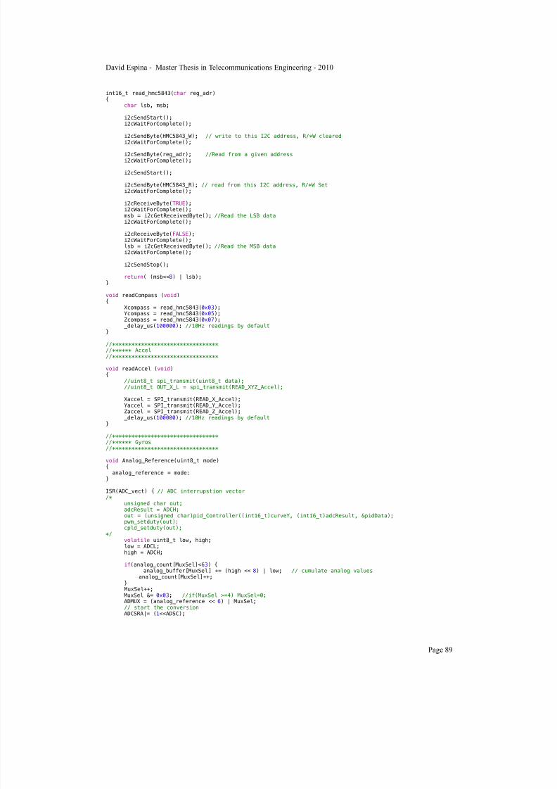
7/22/2019 Gyro With Avr
http://slidepdf.com/reader/full/gyro-with-avr 91/101
int16_t read_hmc5843(char reg_adr){
char lsb, msb;
i2cSendStart(); i2cWaitForComplete(); i2cSendByte(HMC5843_W);
// write to this I2C address, R/*W cleared i2cWaitForComplete();
i2cSendByte(reg_adr); //Read from a given address i2cWaitForComplete(); i2cSendStart(); i2cSendByte(HMC5843_R); // read from this I2C address, R/*W Set i2cWaitForComplete(); i2cReceiveByte(TRUE); i2cWaitForComplete(); msb = i2cGetReceivedByte(); //Read the LSB data i2cWaitForComplete();
i2cReceiveByte(FALSE); i2cWaitForComplete(); lsb = i2cGetReceivedByte(); //Read the MSB data i2cWaitForComplete(); i2cSendStop(); return( (msb<<8) | lsb);
}
void readCompass (void){ Xcompass = read_hmc5843(0x03); Ycompass = read_hmc5843(0x05); Zcompass = read_hmc5843(0x07); _delay_us(100000); //10Hz readings by default}
//*********************************//****** Accel//*********************************
void readAccel (void){ //uint8_t spi_transmit(uint8_t data); //uint8_t OUT_X_L = spi_transmit(READ_XYZ_Accel);
Xaccel = SPI_transmit(READ_X_Accel);Yaccel = SPI_transmit(READ_Y_Accel); Zaccel = SPI_transmit(READ_Z_Accel);_delay_us(100000); //10Hz readings by default
}
//*********************************//****** Gyros//*********************************
void Analog_Reference(uint8_t mode){ analog_reference = mode;}
ISR(ADC_vect) { // ADC interrupstion vector/* unsigned char out; adcResult = ADCH; out = (unsigned char)pid_Controller((int16_t)curveY, (int16_t)adcResult, &pidData); pwm_setduty(out); cpld_setduty(out);*/ volatile uint8_t low, high; low = ADCL;
high = ADCH;
if(analog_count[MuxSel]<63) { analog_buffer[MuxSel] += (high << 8) | low; // cumulate analog values analog_count[MuxSel]++; } MuxSel++; MuxSel &= 0x03; //if(MuxSel >=4) MuxSel=0; ADMUX = (analog_reference << 6) | MuxSel; // start the conversion ADCSRA|= (1<<ADSC);
David Espina - Master Thesis in Telecommunications Engineering - 2010
Page 89

7/22/2019 Gyro With Avr
http://slidepdf.com/reader/full/gyro-with-avr 92/101
}
void Read_adc_raw(void){ int i; uint16_t temp1;
uint8_t temp2;
// ADC readings... for (i=0;i<6;i++) { do{ temp1= analog_buffer[sensors[i]]; // sensors[] maps sensors to correct order
temp2= analog_count[sensors[i]]; } while(temp1 != analog_buffer[sensors[i]]); // Check if there was an ADC interrupt duringreadings...
if (temp2>0)AN[i] = (temp1)/(temp2); // Check for divide by zero CAST TO FLOAT!!!!
} // Initialization for the next readings... for (int i=0;i<6;i++){ do{ analog_buffer[i]=0; analog_count[i]=0; } while(analog_buffer[i]!=0); // Check if there was an ADC interrupt during initialization... }}
void readGyroXY (void){
XgyroXY = analog_buffer[1]; // need to check correspondance to each parameter YgyroXY = analog_buffer[2]; VRefgyroXY = analog_buffer[3]; _delay_us(100000); //10Hz readings by default}
void readGyroYZ (void){
XgyroYZ = analog_buffer[4]; YgyroYZ = analog_buffer[5]; VRefgyroYZ = analog_buffer[6]; _delay_us(100000); //10Hz readings by default
}
//*********************************//****** Bluetooth//*********************************
void packDataToSend(void){ //implement here the sending secuence according to iNEMO specifications //might need to change send a String or Numeric instead of CHAR
char a = Xcompass; sw_UART_Transmit_char(a); Xcompass; Ycompass; Zcompass; Xaccel; Yaccel; Zaccel; XgyroXY; YgyroXY; VRefgyroXY; XgyroYZ; YgyroYZ; VRefgyroYZ;
}// end of iMYou.c
constants.h//constants.h/*// CPU clock speed * System clock in Hz. *///#define F_CPU 16000000UL // 16MHz processor#define F_CPU 4000000UL // 4MHz processor#define CYCLES_PER_US ((F_CPU+500000)/1000000) // cpu cycles per microsecond#define ONE_SEC 1000000
David Espina - Master Thesis in Telecommunications Engineering - 2010
Page 90
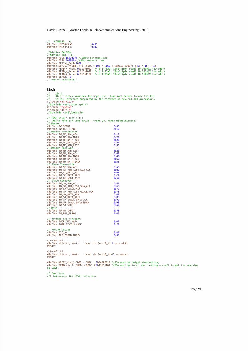
7/22/2019 Gyro With Avr
http://slidepdf.com/reader/full/gyro-with-avr 93/101
/* COMPASS */#define HMC5843_W 0x3C#define HMC5843_R 0x3D
//#define FALSE 0//#define TRUE -1#define FOSC 16000000 //16MHz external osc
#define FOSC 4000000 //4MHz external osc#define SERIAL_BAUD 9600#define SERIAL_MYUBRR (((((FOSC * 10) / (16L * SERIAL_BAUD)) + 5) / 10) - 1)#define READ_X_Accel 0b11101000 // b 1(READ) 1(multiple read) 10 1000(X low addr)#define READ_Y_Accel 0b11101010 // b 1(READ) 1(multiple read) 10 1010(X low addr)#define READ_Z_Accel 0b11101100 // b 1(READ) 1(multiple read) 10 1100(X low addr)#define DEFAULT 0// end of constants.h
i2c.h// i2c.h// This library provides the high-level functions needed to use the I2C// serial interface supported by the hardware of several AVR processors.#include <avr/io.h>//#include <avr/interrupt.h>#include "types.h"#include "defs.h"//#include <util/delay.h>
// TWSR values (not bits)// (taken from avr-libc twi.h - thank you Marek Michalkiewicz)
// Master#define TW_START 0x08#define TW_REP_START 0x10// Master Transmitter#define TW_MT_SLA_ACK 0x18#define TW_MT_SLA_NACK 0x20#define TW_MT_DATA_ACK 0x28#define TW_MT_DATA_NACK 0x30#define TW_MT_ARB_LOST 0x38// Master Receiver#define TW_MR_ARB_LOST 0x38#define TW_MR_SLA_ACK 0x40#define TW_MR_SLA_NACK 0x48#define TW_MR_DATA_ACK 0x50#define TW_MR_DATA_NACK 0x58// Slave Transmitter#define TW_ST_SLA_ACK 0xA8#define TW_ST_ARB_LOST_SLA_ACK 0xB0#define TW_ST_DATA_ACK 0xB8#define TW_ST_DATA_NACK 0xC0#define TW_ST_LAST_DATA 0xC8// Slave Receiver
#define TW_SR_SLA_ACK
0x60#define TW_SR_ARB_LOST_SLA_ACK 0x68#define TW_SR_GCALL_ACK 0x70#define TW_SR_ARB_LOST_GCALL_ACK 0x78#define TW_SR_DATA_ACK 0x80#define TW_SR_DATA_NACK 0x88#define TW_SR_GCALL_DATA_ACK 0x90#define TW_SR_GCALL_DATA_NACK 0x98#define TW_SR_STOP 0xA0// Misc#define TW_NO_INFO 0xF8#define TW_BUS_ERROR 0x00
// defines and constants#define TWCR_CMD_MASK 0x0F#define TWSR_STATUS_MASK 0xF8
// return values#define I2C_OK 0x00#define I2C_ERROR_NODEV 0x01
#ifndef sbi#define sbi(var, mask) ((var) |= (uint8_t)(1 << mask))
#endif
#ifndef cbi#define cbi(var, mask) ((var) &= (uint8_t)~(1 << mask))#endif
#define WRITE_sda() DDRD = DDRC | 0b00000010 //SDA must be output when writing#define READ_sda() DDRD = DDRC & 0b11111101 //SDA must be input when reading - don't forget the resistoron SDA!!
// functions//! Initialize I2C (TWI) interface
David Espina - Master Thesis in Telecommunications Engineering - 2010
Page 91

7/22/2019 Gyro With Avr
http://slidepdf.com/reader/full/gyro-with-avr 94/101
void i2cInit(void);
//! Set the I2C transaction bitrate (in KHz)void i2cSetBitrate(unsigned short bitrateKHz);
// Low-level I2C transaction commands//! Send an I2C start condition in Master mode
void i2cSendStart(void);//! Send an I2C stop condition in Master modevoid i2cSendStop(void);//! Wait for current I2C operation to completevoid i2cWaitForComplete(void);//! Send an (address|R/W) combination or a data byte over I2Cvoid i2cSendByte(unsigned char data);//! Receive a data byte over I2C// ackFlag = TRUE if recevied data should be ACK'ed// ackFlag = FALSE if recevied data should be NACK'edvoid i2cReceiveByte(unsigned char ackFlag);//! Pick up the data that was received with i2cReceiveByte()unsigned char i2cGetReceivedByte(void);//! Get current I2c bus status from TWSRunsigned char i2cGetStatus(void);void delay_ms(uint16_t x);
// high-level I2C transaction commands
//! send I2C data to a device on the bus (non-interrupt based)unsigned char i2cMasterSendNI(unsigned char deviceAddr, unsigned char length, unsigned char* data);//! receive I2C data from a device on the bus (non-interrupt based)unsigned char i2cMasterReceiveNI(unsigned char deviceAddr, unsigned char length, unsigned char *data);
/********************* ****I2C Functions**** *********************/
void i2cInit(void){ // set i2c bit rate to 40KHz i2cSetBitrate(100); // enable TWI (two-wire interface) sbi(TWCR, TWEN); // Enable TWI}
void i2cSetBitrate(unsigned short bitrateKHz){ unsigned char bitrate_div; // set i2c bitrate // SCL freq = F_CPU/(16+2*TWBR)) cbi(TWSR, TWPS0); cbi(TWSR, TWPS1);
//calculate bitrate division bitrate_div = ((F_CPU/4000l)/bitrateKHz); if(bitrate_div >= 16) bitrate_div = (bitrate_div-16)/2; outb(TWBR, bitrate_div);
}
void i2cSendStart(void){ WRITE_sda(); // send start condition TWCR = (1<<TWINT)|(1<<TWSTA)|(1<<TWEN);}
void i2cSendStop(void){ // transmit stop condition TWCR = (1<<TWINT)|(1<<TWEN)|(1<<TWSTO);}
void i2cWaitForComplete(void){ int i = 0; //time out variable
// wait for i2c interface to complete operation while ((!(TWCR & (1<<TWINT))) && (i < 90)) i++; if (i>88) printf("complete timed out\n");}
void i2cSendByte(unsigned char data){ _delay_ms(1); //printf("sending 0x%x\n", data); WRITE_sda();
David Espina - Master Thesis in Telecommunications Engineering - 2010
Page 92

7/22/2019 Gyro With Avr
http://slidepdf.com/reader/full/gyro-with-avr 95/101
// save data to the TWDR TWDR = data; // begin send TWCR = (1<<TWINT)|(1<<TWEN);}
void i2cReceiveByte(unsigned char ackFlag)
{ // begin receive over i2c if( ackFlag ) { // ackFlag = TRUE: ACK the recevied data outb(TWCR, (inb(TWCR)&TWCR_CMD_MASK)|BV(TWINT)|BV(TWEA)); } else { // ackFlag = FALSE: NACK the recevied data outb(TWCR, (inb(TWCR)&TWCR_CMD_MASK)|BV(TWINT)); }}
unsigned char i2cGetReceivedByte(void){ // retieve received data byte from i2c TWDR return( inb(TWDR) );}
unsigned char i2cGetStatus(void){ // retieve current i2c status from i2c TWSR
return( inb(TWSR) );}// end of i2c.h
SPI\spi.h// spi.h#ifndef __SPI_H#define __SPI_H
#include <avr/io.h>
void spi_init();uint8_t spi_transmit(uint8_t data);int16_t SPI_transmit(char data) ;#endif// end of spi.h
SPI\spi.c// spi.c
#include "spi.h"void spi_init() { // set SCK and MOSI as output (SS/PB0 must be set as output, when SPI is master) DDRB |= (_BV(PB0) | _BV(PB1) | _BV(PB2));
// enable spi, set as master, scale sck freq with 128 // SPCR |= (_BV(SPE) | _BV(MSTR) | _BV(SPR1) | _BV(SPR0));
// enable spi, set as master, scale sck freq with 4 SPCR |= (_BV(SPE) | _BV(MSTR)); // double SPI speed //SPSR |= _BV(SPI2X);
}
uint8_t spi_transmit(uint8_t data) { // set SS low PORTB &= ~_BV(PB0); SPDR = data; // Wait for transmission complete while(!(SPSR & (1<<SPIF))); return SPDR;// IdKnw if I get the OUT_X_L here
}
uint8_t SPI_receive(void){
uint8_t data;// Wait for reception completewhile(!(SPSR & (1<<SPIF)));
data = SPDR;
// set SS high to cut the SCK and stop reading
David Espina - Master Thesis in Telecommunications Engineering - 2010
Page 93
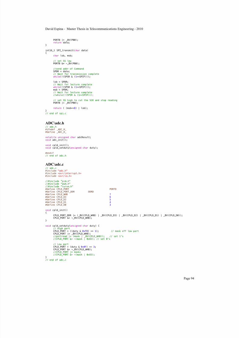
7/22/2019 Gyro With Avr
http://slidepdf.com/reader/full/gyro-with-avr 96/101
PORTB |= _BV(PB0);return data;
}
int16_t SPI_transmit(char data){ char lsb, msb;
// set SS low PORTB &= ~_BV(PB0); //send addr of Command SPDR = data; // Wait for transmission complete while(!(SPSR & (1<<SPIF))); lsb = SPDR; // Wait for lecture complete while(!(SPSR & (1<<SPIF))); msb = SPDR; // Wait for lecture complete //while(!(SPSR & (1<<SPIF)));
// set SS high to cut the SCK and stop reading PORTB |= _BV(PB0);
return ( (msb<<8) | lsb);}// end of spi.c
ADC\adc.h// adc.h#ifndef _ADC_H_#define _ADC_H_
volatile unsigned char adcResult;void adc_init();
void cpld_init();void cpld_setduty(unsigned char duty);
#endif// end of adc.h
ADC\adc.c// adc.c#include "adc.h"#include <avr/interrupt.h>#include <avr/io.h>
//#include "pid.h"//#include "pwm.h"//#include "curve.h"#define CPLD_PORT PORTD#define CPLD_PORT_DDR DDRD#define CPLD_WHB 7#define CPLD_D3 6#define CPLD_D2 5#define CPLD_D1 4#define CPLD_D0 3
void cpld_init(){ CPLD_PORT_DDR |= (_BV(CPLD_WHB) | _BV(CPLD_D3) | _BV(CPLD_D2) | _BV(CPLD_D1) | _BV(CPLD_D0)); CPLD_PORT &= ~_BV(CPLD_WHB);}
void cpld_setduty(unsigned char duty) { // High part CPLD_PORT = ((duty & 0xF0) >> 1); // mask off low part CPLD_PORT |= _BV(CPLD_WHB);
//portread |= (mask | _BV(CPLD_WHB)); // set 1's //CPLD_PORT &= ~(mask | 0x83); // set 0's
// Low part CPLD_PORT = (duty & 0x0F) << 3; CPLD_PORT &= ~_BV(CPLD_WHB); //CPLD_PORT |= mask; //CPLD_PORT &= ~(mask | 0x83);}// end of adc.c
David Espina - Master Thesis in Telecommunications Engineering - 2010
Page 94

7/22/2019 Gyro With Avr
http://slidepdf.com/reader/full/gyro-with-avr 97/101
sw UART\sw_uart.h// sw_uart.h/*****************************************Filename : sw_uart.hAuthor : Prashant MehtaDate : 26-06-2009
NOTE
: Modified by David Espina 24-09-2010******************************************//********************************************************************************* Header file for SOFTWARE UART using timer* Timer 0 is set to 3 times the required baud rate because data sampling has to be done 3 times per bit* 5,6,7,8 bit Tx and Rx possible by this s/w UART* 1 or 2 Stop bits as pre-defined by user* Possible to use parity bit (even or odd) along with data frame* parity_error flag set if parity error* Use sw_uart_config.h to configure Software UART. Dont make any changes here.* sw_uart_init() -- Function to initialize Software UART* sw_UART_Transmit_char(char) -- Function for Transmitting character* sw_UART_Receive_char() -- Function for Receiving character******************************************************************************/#include<avr/io.h>#include<avr/interrupt.h>#include"sw_uart_config.h"#define TRUE 1#define FALSE 0
#define IN_BUF_SIZE 256
/******************************************** Function Prototypes************************************************/void set_tx_pin_high(void); void set_tx_pin_low(void);void timer0_init(void);void sw_uart_init(void);static void sw_uart_io_init(void);void sw_UART_Transmit_char(char ch);char sw_UART_Receive_char( void );int get_rx_pin_status(void);void flush_input_buffer(void);void frame_calc(unsigned char);void softuart_turn_rx_on(void);void softuart_turn_rx_off(void);/****************************************************************************************************//******************************************* Software UART variables**********************************************/volatile static unsigned char inbuf[IN_BUF_SIZE];volatile static unsigned char qin = 0;volatile static unsigned char qout = 0;
volatile unsigned static char flag_tx_ready;volatile unsigned static char timer_tx_ctr;volatile unsigned static char bits_left_in_tx;volatile unsigned static char tx_num_of_bits;volatile unsigned static short internal_tx_buffer;volatile unsigned static char user_tx_buffer;volatile unsigned static char num_of_databits;volatile unsigned static char parity_error;
volatile static unsigned char flag_rx_off;volatile static unsigned char flag_rx_ready;volatile static unsigned char tx_num_of_ones=0;volatile static unsigned char rx_num_of_ones=0;volatile static unsigned int frame;volatile static unsigned int rx_parity_bit;/**************************************************************************************************//* Function to initialize uart PD37 as TX pin and PD2 as RX pin. Also initialize timer 0 for delay of 3 times the baud rate*/void sw_uart_init(void){ sw_uart_io_init();
/* Condition to double the baud rate if U2X2 = 1 */
if(U2X2 == 1) { baudrate = 2 * (BAUD_RATE); } else baudrate = BAUD_RATE; /*************************************************/
flag_tx_ready = FALSE; tx_num_of_bits = NUM_OF_DATABITS+NUM_OF_STOPBITS+1+PARITY_BIT; set_tx_pin_high(); timer0_init(); // start timer 0
}
David Espina - Master Thesis in Telecommunications Engineering - 2010
Page 95

7/22/2019 Gyro With Avr
http://slidepdf.com/reader/full/gyro-with-avr 98/101
/****************************************************************************************************//****************************************** Timer ISR on oveflow***********************************************/ISR (TIMER0_COMP_vect) // Interrupt on compare match{ char mask; static unsigned char flag_rx_waiting_for_stop_bit = FALSE;
static unsigned char rx_mask; static char timer_rx_ctr; // Counter for sampling at reciption static char bits_left_in_rx; static unsigned char internal_rx_buffer; char start_bit, flag_in; /*** Transmitter section ***/ if(flag_tx_ready) {
if(--timer_tx_ctr<=0) {
mask=internal_tx_buffer&1; internal_tx_buffer>>=1; if(mask) { set_tx_pin_high(); } else { set_tx_pin_low();
} timer_tx_ctr = 3; if ( --bits_left_in_tx<=0 ) { flag_tx_ready = FALSE; } } } /*** Reciever section ***/ if ( flag_rx_off == FALSE ) { if ( flag_rx_waiting_for_stop_bit ) // for stop bit { if ( --timer_rx_ctr <= 0 ){ if(get_rx_pin_status()) { flag_rx_waiting_for_stop_bit = FALSE; flag_rx_ready = FALSE; inbuf[qin] = internal_rx_buffer; if ( ++qin>=IN_BUF_SIZE ) { qin = 0;
}
} } } else {if ( flag_rx_ready == FALSE ) { start_bit = get_rx_pin_status(); // test for start bit if ( start_bit == 0 ) { flag_rx_ready = TRUE; internal_rx_buffer= 0; timer_rx_ctr= 4; // here 4 so that bit is sampled at middle bits_left_in_rx = NUM_OF_DATABITS+PARITY_BIT; rx_mask=1; } } else
{ // rx_busy if ( --timer_rx_ctr <= 0 ) { // rcv timer_rx_ctr = 3; flag_in = get_rx_pin_status(); if(!PARITY_BIT) // No parity bit { if ( flag_in ) // OR with 1 according to rx pin status { internal_rx_buffer |= rx_mask; }
David Espina - Master Thesis in Telecommunications Engineering - 2010
Page 96
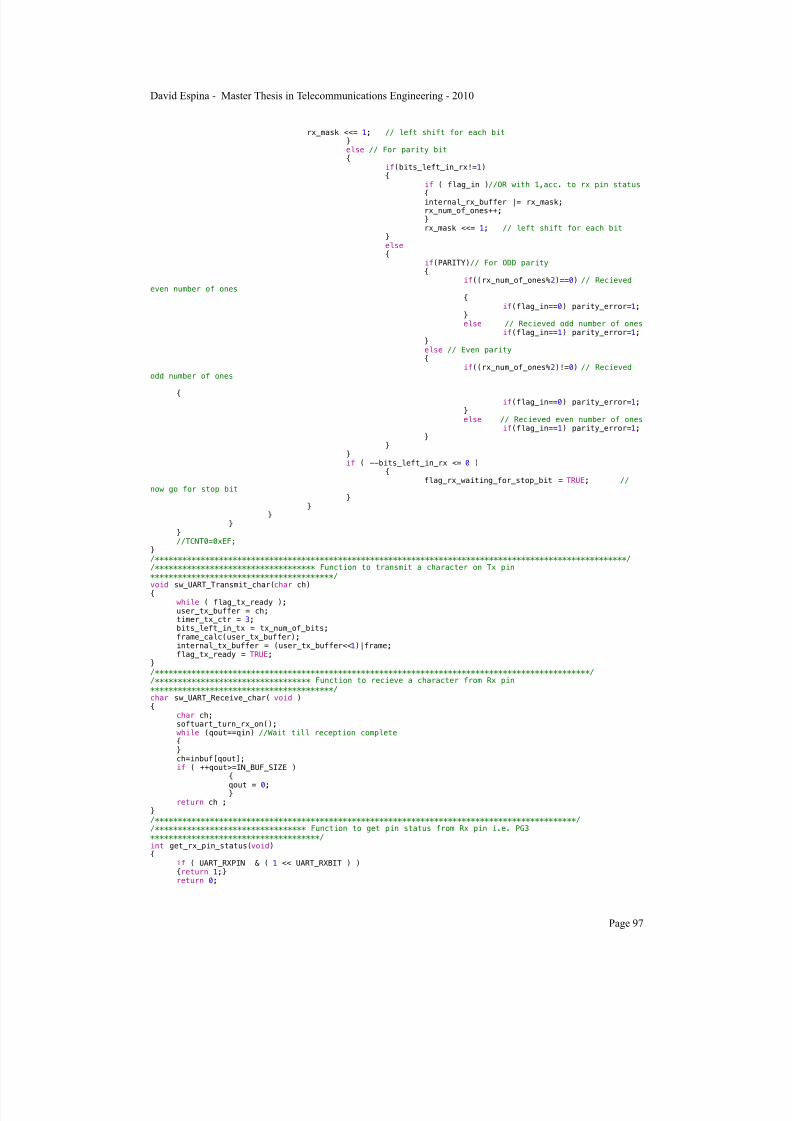
7/22/2019 Gyro With Avr
http://slidepdf.com/reader/full/gyro-with-avr 99/101
rx_mask <<= 1; // left shift for each bit } else // For parity bit { if(bits_left_in_rx!=1) { if ( flag_in )//OR with 1,acc. to rx pin status { internal_rx_buffer |= rx_mask; rx_num_of_ones++; } rx_mask <<= 1; // left shift for each bit } else { if(PARITY)// For ODD parity { if((rx_num_of_ones%2)==0) // Recieved
even number of ones { if(flag_in==0) parity_error=1; } else // Recieved odd number of ones if(flag_in==1) parity_error=1; } else // Even parity { if((rx_num_of_ones%2)!=0) // Recievedodd number of ones
{ if(flag_in==0) parity_error=1; } else // Recieved even number of ones if(flag_in==1) parity_error=1; } } } if ( --bits_left_in_rx <= 0 ) { flag_rx_waiting_for_stop_bit = TRUE; //
now go for stop bit } } } } } //TCNT0=0xEF;}/*******************************************************************************************************//*********************************** Function to transmit a character on Tx pin****************************************/void sw_UART_Transmit_char(char ch){ while ( flag_tx_ready ); user_tx_buffer = ch; timer_tx_ctr = 3; bits_left_in_tx = tx_num_of_bits; frame_calc(user_tx_buffer); internal_tx_buffer = (user_tx_buffer<<1)|frame;
flag_tx_ready = TRUE;}/***********************************************************************************************//********************************** Function to recieve a character from Rx pin****************************************/char sw_UART_Receive_char( void ){ char ch; softuart_turn_rx_on(); while (qout==qin) //Wait till reception complete { } ch=inbuf[qout]; if ( ++qout>=IN_BUF_SIZE ) {
qout = 0; } return ch ;}/********************************************************************************************//********************************* Function to get pin status from Rx pin i.e. PG3*************************************/int get_rx_pin_status(void){ if ( UART_RXPIN & ( 1 << UART_RXBIT ) ) {return 1;} return 0;
David Espina - Master Thesis in Telecommunications Engineering - 2010
Page 97

7/22/2019 Gyro With Avr
http://slidepdf.com/reader/full/gyro-with-avr 100/101
}/*****************************************************************************//***************************************** Function to turn receiption ON***********************************************/void softuart_turn_rx_on( void ){ flag_rx_off = FALSE;
}/************************************************************************************//************************************** Function to turn receiption OFF*************************************************/void softuart_turn_rx_off( void ){ flag_rx_off = TRUE;}/***********************************************************************************************//************************************ Function to initialise s/w uart Tx and Rx ports***********************************/static void sw_uart_io_init(void){ // TX-Pin as output UART_TXDDR |= ( 1 << UART_TXBIT ); // RX-Pin as input UART_RXDDR &= ~( 1 << UART_RXBIT ); // RX-pin pull-up UART_RXPORT |= (1 << UART_RXBIT );}/*****************************************************************************************//****************************************** Function to set Tx pin(PD3) high********************************************/
void set_tx_pin_high(void){ UART_TXPORT |= ( 1<< UART_TXBIT );}/********************************************************************************************//*************************************** Function to set Tx pin(PD3) low**********************************************/void set_tx_pin_low(void){ UART_TXPORT &= ~( 1<<UART_TXBIT );}/*******************************************************************************************//******************************* Function for clearing contents of input buffer**************************************/void flush_input_buffer(void){ qin = 0; qout = 0;}/*************************************************************************************************//*************************** Function for adding parity bit & stop bits into data frame*******************************/void frame_calc(unsigned char ch){ unsigned char temp=0,i; for(i=0;i<=NUM_OF_DATABITS;i++) { temp=ch&1; ch>>=1; if(temp==1) tx_num_of_ones++; } if(PARITY_BIT) // For PARITY BIT { if((tx_num_of_ones%2)==0) //EVEN number of ones { if(PARITY) // ODD PARITY { if (NUM_OF_STOPBITS==1) // For 1 stop-bit { frame=0x600>>(8-NUM_OF_DATABITS); } else // For 2 stop-bits { frame=0xe00>>(8-NUM_OF_DATABITS);
} } else //EVEN PARITY { if (NUM_OF_STOPBITS==1) // For 1 stop-bit { frame=0x400>>(8-NUM_OF_DATABITS); } else // For 2 stop-bits { frame=0xc00>>(8-NUM_OF_DATABITS); }
David Espina - Master Thesis in Telecommunications Engineering - 2010
Page 98

7/22/2019 Gyro With Avr
http://slidepdf.com/reader/full/gyro-with-avr 101/101
} } else // ODD Number of ones { if(!PARITY) // EVEN PARITY { if (NUM_OF_STOPBITS==1) // For 1 stop-bit { frame=0x600>>(8-NUM_OF_DATABITS); } else // For 2 stop-bits { frame=0xe00>>(8-NUM_OF_DATABITS); } } else //ODD PARITY { if (NUM_OF_STOPBITS==1) // For 1 stop-bit { frame=0x400>>(8-NUM_OF_DATABITS); } else // For 2 stop-bits { frame=0xc00>>(8-NUM_OF_DATABITS); } } } } else // No parity bit {
if (NUM_OF_STOPBITS==1) // For 1 stop-bit { frame=0x200>>(8-NUM_OF_DATABITS); } else // For 2 stop-bits { frame=0x600>>(8-NUM_OF_DATABITS); } }}// end of sw_uart.h
David Espina - Master Thesis in Telecommunications Engineering - 2010