

GypWall rapid dB Plus/media/Files/British...0115 945 6123 [email protected] C04. S01....
31
C04. S10. P02 – P12 GypWall RAPID dB Plus Including C04. S01. P02 – P18 Partitions introduction This section includes updated information, added since it was first published in December 2015. Last updated 14/06/2017 !
Transcript of GypWall rapid dB Plus/media/Files/British...0115 945 6123 [email protected] C04. S01....

C04.S10.P02–P12 GypWallrapid dB Plus IncludingC04.S01.P02–P18
Partitionsintroduction
Thissectionincludesupdatedinformation,addedsinceitwasfirst
publishedinDecember2015.
Last updated 14/06/2017!

C04
Intr
odu
ctio
nPa
rtit
ion
s
PartitionsThis section contains a full range of lightweight partition and wall systems for use in new and existing buildings. They cover all applications, from simple space division to high performance walls

C04. S01. P02 0115 945 6123 [email protected]
C04Introdu
ctionPartition
s
Partitions
British Gypsum offers a full range of lightweight partition and wall systems. Our systems are non-loadbearing and constructed using modern, drylining techniques. British Gypsum metal framed partitions and walls can be used in all types of new and existing buildings, including private and social housing, apartments, healthcare, educational facilities, recreational and industrial properties.
They cover all applications, from simple space division, through to high performance walls designed to meet the most demanding fire resistance, sound insulation, impact and height requirements. British Gypsum partition systems are constructed using lightweight materials, which can give rise to significant savings in structural design compared to masonry alternatives. Big benefits also include the speed of installation and reduction to overall build costs.
Buildings need to evolve throughout their life to suit changing demands placed upon them. Our lightweight partition systems are easy to reconfigure with minimal impact to both building and occupants resulting in less disruption, optimising the transformation process.
You may also be interested in...
For unique performance situations with specialist requirements: — Curved partitions — Access to build from one side only — High levels of fire resistance — High security including bomb blast
Refer to C05. S01. P02 – Specialist partitions
C04. S01. P03 british-gypsum.com
C04
Intr
odu
ctio
nPa
rtit
ion
s
Partitions
Additional information
Try out The White Book System Selector, an online tool designed to help find the ideal solutions for your project needs. Additional information such as BIM data (Revit), NBS clauses, CAD drawings and other associated items can be downloaded. Visit british-gypsum.com
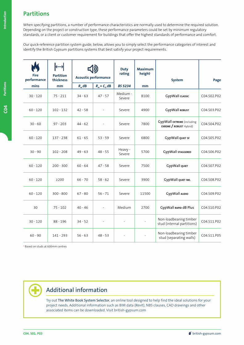
When specifying partitions, a number of performance characteristics are normally used to determine the required solution. Depending on the project or construction type, these performance parameters could be set by minimum regulatory standards, or a client or customer requirement for buildings that offer the highest standards of performance and comfort.
Our quick-reference partition system guide, below, allows you to simply select the performance categories of interest and identify the British Gypsum partitions systems that best satisfy your project requirements.
Fire
performancePartition thickness
Acoustic performance
Duty rating
Maximum height1
System Page
mins mm Rw dB Rw + Ctr dB BS 5234 mm
30 - 120 75 - 211 34 - 63 47 - 57Medium -
Severe8100 GypWall classic C04.S02.P02
60 - 120 102 - 132 42 - 58 - Severe 4900 GypWall robust C04.S03.P02
30 - 60 97 - 203 44 - 62 - Severe 7800GypWall extreme (including
exreme / robust Hybrid)C04.S04.P02
60 - 120 137 - 238 61 - 65 53 - 59 Severe 6800 GypWall quiet sf C04.S05.P02
30 - 90 102 - 208 49 - 63 48 - 55Heavy - Severe
5700 GypWall staggered C04.S06.P02
60 - 120 200 - 300 60 - 64 47 - 58 Severe 7500 GypWall quiet C04.S07.P02
60 - 120 ≥200 66 - 70 58 - 62 Severe 3900 GypWall quiet iwl C04.S08.P02
60 - 120 300 - 800 67 - 80 56 - 71 Severe 11500 GypWall audio C04.S09.P02
30 75 - 102 40 - 46 - Medium 2700 GypWall rapid dB Plus C04.S10.P02
30 - 120 88 - 196 34 - 52 - - -Non-loadbearing timber stud (internal partitions)
C04.S11.P02
60 - 90 141 - 293 56 - 63 48 - 53 - -Non-loadbearing timber stud (separating walls)
C04.S11.P05
1 Based on studs at 600mm centres
C04. S01. P04 0115 945 6123 [email protected]
C04Introdu
ctionPartition
s
British Gypsum’s systems are designed and tested to meet every performance requirement and are fully supported by our SpecSure® lifetime system warranty.
This means that when our systems are installed following our guidance they will achieve every performance claim we make, and if they don’t then we’ll put it right.
To maximise the performance achieved on site, consider the following good practice specification guidance:
— Consider flanking transmission at the design stage and ensure construction detailing is specified to eliminate, or at least to minimise, any downgrading of the acoustic performance
— Small openings such as gaps, cracks or holes will conduct airborne sounds and can significantly reduce the sound insulation of a construction. For optimum sound insulation a construction must be airtight
— When designing the layout of rooms requiring separation by sound insulating walls abutting structural steelwork, consideration should be given to the potential loss of sound insulation performance through the steelwork
— Deflection heads, by definition, must be able to move and, therefore, achieving an airtight seal is very difficult without incorporating sophisticated components and techniques. Air leakage at the partition heads will have a detrimental effect on acoustic performance of any partition. Where acoustic performance is a key consideration, steps must be taken to minimise this loss of performance
— A common mistake made when designing a building is to specify a high performance element and then incorporate a lower performing element within it; for example, a door within a partition. Where the difference between insulation is relatively small (7dB or less), there needs to be a comparatively large area of the lower insulation element before the overall sound insulation is significantly affected. However, where there is a greater difference in sound insulation performance between the two elements, this would usually result in a greater reduction of overall sound insulation performance
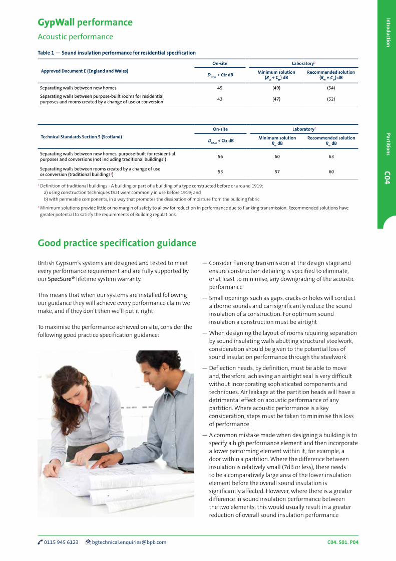
GypWall performanceAcoustic performance
Table 1 — Sound insulation performance for residential specification
Approved Document E (England and Wales)
On-site Laboratory2
DnT,w
+ Ctr dBMinimum solution
(Rw
+ Ctr
) dBRecommended solution
(Rw
+ Ctr
) dB
Separating walls between new homes 45 (49) (54)
Separating walls between purpose-built rooms for residential purposes and rooms created by a change of use or conversion
43 (47) (52)
Technical Standards Section 5 (Scotland)
On-site Laboratory2
DnT,w
+ Ctr dBMinimum solution
Rw
dBRecommended solution
Rw
dB
Separating walls between new homes, purpose-built for residential purposes and conversions (not including traditional buildings1)
56 60 63
Separating walls between rooms created by a change of use or conversion (traditional buildings1)
53 57 60
1 Definition of traditional buildings - A building or part of a building of a type constructed before or around 1919:
a) using construction techniques that were commonly in use before 1919; and
b) with permeable components, in a way that promotes the dissipation of moisture from the building fabric.
2 Minimum solutions provide little or no margin of safety to allow for reduction in performance due to flanking transmission. Recommended solutions have
greater potential to satisfy the requirements of Building regulations.
Good practice specification guidance
C04. S01. P05 british-gypsum.com
C04
Intr
odu
ctio
nPa
rtit
ion
s
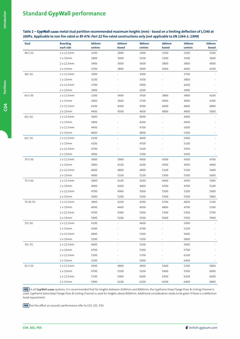
Standard GypWall performance
Table 2 – GypWall classic metal stud partition recommended maximum heights (mm) - based on a limiting deflection of L/240 at 200Pa. Applicable to non fire-rated or BS 476: Part 22 fire-rated constructions only (not applicable to EN 1364-1: 1999)
Stud Boarding
each side
600mm
centres
600mm
boxed
400mm
centres
400mm
boxed
300mm
centres
300mm
boxed
48 S 50 1 x 12.5mm 2500 2800 2900 3200 3100 3500
1 x 15mm 2800 3000 3100 3300 3300 3600
2 x 12.5mm 3400 3600 3600 3800 3800 4000
2 x 15mm 3700 3800 3900 4000 4000 4200
48 I 50 1 x 12.5mm 2900 - 3400 - 3700 -
1 x 15mm 3100 - 3500 - 3800 -
2 x 12.5mm 3700 - 3900 - 4200 -
2 x 15mm 3900 - 4200 - 4400 -
60 S 50 1 x 12.5mm 3200 3400 3500 3800 3800 4200
1 x 15mm 3400 3600 3700 4000 4000 4300
2 x 12.5mm 4100 4300 4300 4600 4600 4800
2 x 15mm 4400 4500 4600 4800 4800 5000
60 I 50 1 x 12.5mm 3600 - 4000 - 4400 -
1 x 15mm 3800 - 4200 - 4500 -
2 x 12.5mm 4400 - 4700 - 5000 -
2 x 15mm 4600 - 4900 - 5200 -
60 I 70 1 x 12.5mm 4100 - 4600 - 5000 -
1 x 15mm 4200 - 4700 - 5100 -
2 x 12.5mm 4700 - 5100 - 5500 -
2 x 15mm 4900 - 5300 - 5600 -
70 S 50 1 x 12.5mm 3600 3900 4000 4300 4300 4700
1 x 15mm 3800 4100 4200 4500 4500 4900
2 x 12.5mm 4600 4800 4900 5100 5100 5400
2 x 15mm 4900 5100 5100 5300 5300 5600
70 S 60 1 x 12.5mm 3800 4100 4200 4600 4500 5000
1 x 15mm 4000 4300 4400 4700 4700 5100
2 x 12.5mm 4700 4900 5000 5300 5200 5600
2 x 15mm 5000 5200 5200 5500 5500 5800
70 AS 50 1 x 12.5mm 3800 4200 4300 4700 4600 5100
1 x 15mm 4000 4400 4500 4800 4700 5200
2 x 12.5mm 4700 5000 5000 5300 5300 5700
2 x 15mm 5000 5200 5300 5600 5500 5900
70 I 50 1 x 12.5mm 4100 - 4600 - 5000 -
1 x 15mm 4300 - 4700 - 5100 -
2 x 12.5mm 4900 - 5300 - 5600 -
2 x 15mm 5200 - 5500 - 5800 -
70 I 70 1 x 12.5mm 4600 - 5100 - 5600 -
1 x 15mm 4700 - 5300 - 5700 -
2 x 12.5mm 5300 - 5700 - 6100 -
2 x 15mm 5500 - 5900 - 6300 -
92 S 50 1 x 12.5mm 4500 4800 4900 5400 5300 5800
1 x 15mm 4700 5100 5200 5600 5500 6000
2 x 12.5mm 5700 5900 6000 6300 6200 6600
2 x 15mm 5900 6100 6200 6500 6400 6800
In all GypWall classic systems, it is recommended that for heights between 4200mm and 8000mm, the Gypframe Deep Flange Floor & Ceiling Channel is
used. Gypframe Extra Deep Flange Floor & Ceiling Channel is used for heights above 8000mm. Additional consideration needs to be given if there is a deflection
head requirement.
For the affect on acoustic performance refer to C02. S01. P30.

C04. S01. P06 0115 945 6123 [email protected]
C04Introdu
ctionPartition
s
Standard GypWall performance (continued)
Table 2 (continued) – GypWall classic metal stud partition recommended maximum heights (mm) - based on a limiting deflection of L/240 at 200Pa. Applicable to non fire-rated or BS 476: Part 22 fire-rated constructions only (not applicable to EN 1364-1: 1999)
Stud Boarding
each side
600mm
centres
600mm
boxed
400mm
centres
400mm
boxed
300mm
centres
300mm
boxed
92 S 60 1 x 12.5mm 4700 5000 5200 5600 5600 6100
1 x 15mm 4900 5300 5400 5800 5800 6300
2 x 12.5mm 5800 6000 6100 6500 6500 6900
2 x 15mm 6000 6200 6300 6700 6600 7000
92 AS 50 1 x 12.5mm 4700 5100 5200 5700 5700 6200
1 x 15mm 4900 5300 5400 5700 5800 6400
2 x 12.5mm 5800 6100 6200 6500 6500 6900
2 x 15mm 6000 6300 6400 6700 6700 7000
92 S 10 1 x 12.5mm 5300 5800 6000 6600 6500 7200
1 x 15mm 5500 6000 6100 6700 6600 7300
2 x 12.5mm 6200 6600 6700 7200 7200 7700
2 x 15mm 6400 6800 6900 7400 7300 7800
92 I 90 1 x 12.5mm 6000 - 6800 - 7400 -
1 x 15mm 6200 - 6900 - 7500 -
2 x 12.5mm 6800 - 7400 - 7900 -
2 x 15mm 6900 - 7500 - 8000 -
146 S 50 1 x 12.5mm 6200 6800 6900 7600 7500 8300
1 x 15mm 6500 7000 7200 7800 7700 8400
2 x 12.5mm 7600 8000 8100 8600 8500 9100
2 x 15mm 7900 8200 8300 8800 8700 9300
146 AS 50 1 x 12.5mm 6600 7100 7300 8000 8000 8800
1 x 15mm 6800 7400 7600 8200 8200 8900
2 x 12.5mm 7800 8200 8400 8900 8900 9500
2 x 15mm 8100 8500 8600 9100 9100 9700
146 I 80 1 x 12.5mm 7900 - 8900 - 9700 -
1 x 15mm 8100 - 9000 - 9800 -
2 x 12.5mm 8800 - 9600 - 10400 -
2 x 15mm 9000 - 9800 - 10500 -
146 TI 90 1 x 12.5mm 8300 - 9400 - 10300 -
1 x 15mm 8400 - 9500 - 10400 -
2 x 12.5mm 9200 - 10100 - 10900 -
2 x 15mm 9400 - 10300 - 11100 -
In all GypWall classic systems, it is recommended that for heights between 4200mm and 8000mm, the Gypframe Deep Flange Floor & Ceiling Channel is
used. Gypframe Extra Deep Flange Floor & Ceiling Channel is used for heights above 8000mm. Additional consideration needs to be given if there is a deflection
head requirement.
For the affect on acoustic performance refer to C02. S01. P30.

C04. S01. P07 british-gypsum.com
C04
Intr
odu
ctio
nPa
rtit
ion
s
Standard GypWall construction detailsTo be read in conjunction with system specific details. Refer to relevant system sections
Stud splicing detail
300m
m30
0mm
600m
m
600m
m
600m
m
1
6
2
3
4
5
1
1 Gypframe 'I' Stud
2 Gypframe 'C' Stud
3 Gypframe AcouStud
4 Gypframe Floor & Ceiling Channel
5 British Gypsum Wafer Head Drywall Screws or British Gypsum Wafer Head Jack-Point Screws
6 Crimp
70mm 146mm
28mm
50m
m
92mm
28mm
50m
m28mm
50m
m
1479
mm
879m
m
279m
m
Centres
at 600mm
thereafter
70mm
AcouStud
146mm
AcouStud
92mm
AcouStud
75mm
38m
m
38m
m
75mm
30m
m
38mm
Centresat
600mm thereafter
1479mm
146mm
stud
75mm
879mm
92mm
stud
60mm
stud
48mm
stud
70mm
stud
75mm 75mm
38m
m
279mm
2 2a
Service cut-outs - Gypframe ‘C’ and Gypframe ‘I’ Studs Service cut-outs - Gypframe AcouStuds

C04. S01. P08 0115 945 6123 [email protected]
C04Introdu
ctionPartition
s
Standard GypWall construction details (continued)
To be read in conjunction with system specific details. Refer to relevant system sections
1
3
9
2
4
1
Base with timber sole plate
2
11
Head and base
5
3 3a
4
Junction with masonry and stop end detail
3
7
8
6
1
4
6
3
10
2
1 Gyproc plasterboard or Glasroc F specialist board
2 Gypframe 'C' Stud
3 Gypframe Floor & Ceiling Channel
4 Gyproc Sealant
5 Bulk fill Gyproc jointing materials (where gap exceeds 5mm)
6 Skirting
7 Floating screed on resilient layer
8 Timber sole plate suitably fixed to structure
9 Internal blockwork
10 DriLyner basic wall lining system
11 Isover insulation
C04. S01. P09 british-gypsum.com
C04
Intr
odu
ctio
nPa
rtit
ion
s
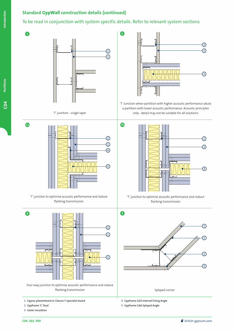
Standard GypWall construction details (continued)
To be read in conjunction with system specific details. Refer to relevant system sections
5
Four way junction to optimise acoustic performance and reduce
flanking transmission
‘T’ junction to optimise acoustic performance and reduce
flanking transmission
1 Gyproc plasterboard or Glasroc F specialist board
2 Gypframe 'C' Stud
3 Isover insulation
4 Gypframe GA5 Internal Fixing Angle
5 Gypframe GA6 Splayed Angle
3
6
‘T’ junction to optimise acoustic performance and reduce
flanking transmission
‘T’ Junction when partition with higher acoustic performance abuts
a partition with lower acoustic performance. Acoustic principles
only - detail may not be suitable for all solutions
Splayed corner
2
1
2
3
1
3
1
2
1
3
2
7b
8 9
‘T’ junction - single layer
7a
2
1
4
2
15
5

C04. S01. P10 0115 945 6123 [email protected]
C04Introdu
ctionPartition
s
Standard GypWall construction details (continued)
To be read in conjunction with system specific details. Refer to relevant system sections
1 Gyproc plasterboard or Glasroc F specialist board
2 Gypframe 'C' Stud
3 Stone mineral wool (minimum density 23kg/m3) (by others)
4 Gyproc Control Joint
5 Gypframe 99 FC 50 Fixing Channel
6 18mm plywood
7 Gypframe Service Support Plate
10 11
2
3
6
Gypframe 99 FC 50 Fixing Channel
(short legs flattened at stud positions)
2
12 13
14
Corner detail - single layer Corner detail - double layer
1
2
Typical control joint
16mm
12mm
12mm
Installing the screw into the side of the Gypframe Service Support Plate and the web of the Gypframe 'C' Stud will avoid creating excessive distortion to
the lining board.
1
2
1
2
1
4
5
1
7
Gypframe Service Support Plate

C04. S01. P11 british-gypsum.com
C04
Intr
odu
ctio
nPa
rtit
ion
s
Standard GypWall construction details (continued)
To be read in conjunction with system specific details. Refer to relevant system sections
1 Gyproc plasterboard or Glasroc F specialist board
2 Gypframe 'C' Stud
3 Gypframe GFS1 Fixing Strap
4 Gypframe Deep Flange Floor & Ceiling Channel
5 Gypframe Extra Deep Flange Floor & Ceiling Channel
6 Gyproc CoreBoard
7 Gyproc FireStrip (continuous)
8 Timber head plate suitably fixed to structure
9 25mm Glasroc F firecase
10 Stone mineral wool (by others)
11 Nogging cut from Gypframe 'C' Stud
50mm
50mm
55mm
15mm
15mm
15mm
15mm
15mm
20mm
25mm
25mm
30mm
25mm
25mm
30mm
15
Deflection head for plus or minus 25mm movement
and 60 minutes fire resistance
Deflection head for 50mm downward movement
and 60 minutes fire resistance
16
Deflection head for plus or minus 25mm movement
and 60 minutes fire resistance
Deflection head for 15mm downward movement
and up to 120 minutes fire resistance
Deflection head for 50mm downward movement
and 60 minutes fire resistance
6 6
4
8
1
7
1
18
19 20
Deflection head for 15mm downward movement
and 60 minutes fire resistance
17
7
9
No fixings should be made through the boards into the flanges of the head channel. The arrow ( ) denotes the position of the uppermost board fixing,
which should be made into Gypframe GFS1 Fixing Strap (or stud nogging in construction detail 16). Continuous Gyproc FireStrip must be installed as shown to
maintain fire performance. Where there is a need for a deflection head in a 90 minute wall, the 120 minute solution can be used (refer to construction detail 16)
or alternatively, please contact the British Gypsum Technical Advice Centre for further guidance.
2
1
3
4
2
1
10
11
5
2
3
7
50mm
50mm
55mm
8
1
7
5
2
3
7
2
3
5
7
1
7
9
2
3
5
7
7 7
C04. S01. P12 0115 945 6123 [email protected]
C04Introdu
ctionPartition
s
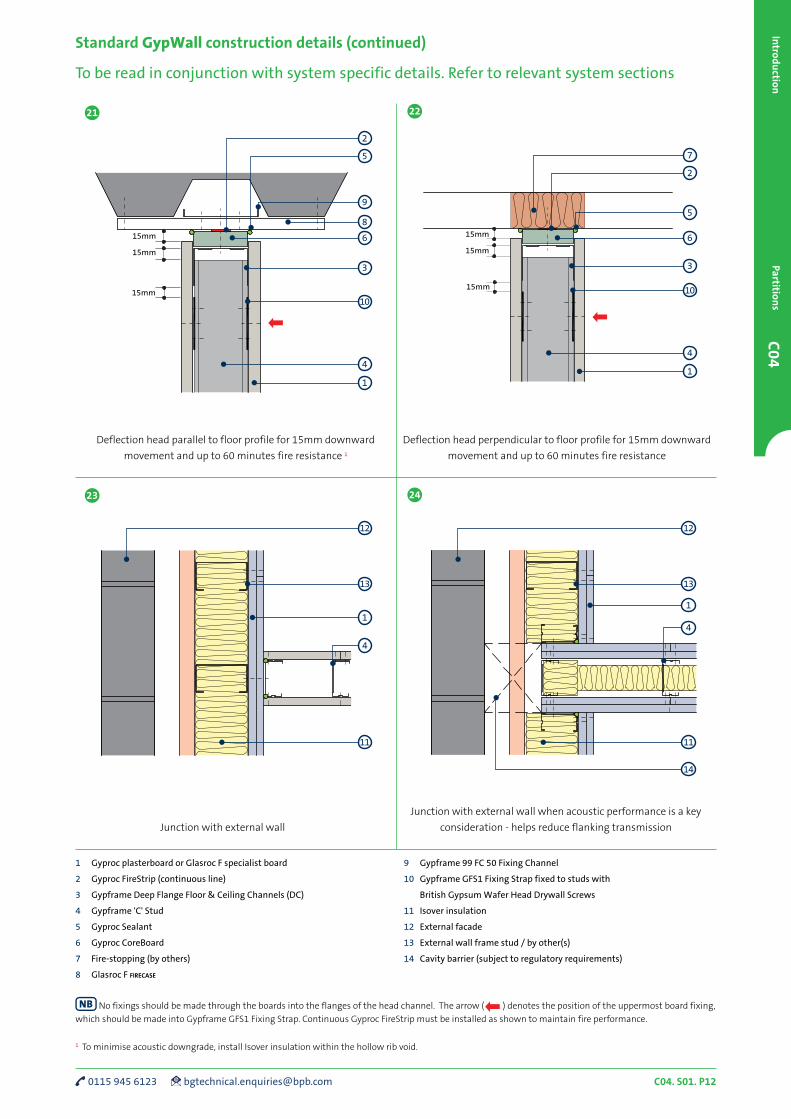
Standard GypWall construction details (continued)
To be read in conjunction with system specific details. Refer to relevant system sections
1 Gyproc plasterboard or Glasroc F specialist board
2 Gyproc FireStrip (continuous line)
3 Gypframe Deep Flange Floor & Ceiling Channels (DC)
4 Gypframe 'C' Stud
5 Gyproc Sealant
6 Gyproc CoreBoard
7 Fire-stopping (by others)
8 Glasroc F firecase
9 Gypframe 99 FC 50 Fixing Channel
10 Gypframe GFS1 Fixing Strap fixed to studs with
British Gypsum Wafer Head Drywall Screws
11 Isover insulation
12 External facade
13 External wall frame stud / by other(s)
14 Cavity barrier (subject to regulatory requirements)
15mm
15mm
15mm
15mm
15mm
15mm
21 22
4
13
Junction with external wall when acoustic performance is a key
consideration - helps reduce flanking transmission
23 24
Deflection head parallel to floor profile for 15mm downward
movement and up to 60 minutes fire resistance 1
Deflection head perpendicular to floor profile for 15mm downward
movement and up to 60 minutes fire resistance
Junction with external wall
No fixings should be made through the boards into the flanges of the head channel. The arrow ( ) denotes the position of the uppermost board fixing,
which should be made into Gypframe GFS1 Fixing Strap. Continuous Gyproc FireStrip must be installed as shown to maintain fire performance.
1 To minimise acoustic downgrade, install Isover insulation within the hollow rib void.
1
5
4
3
10
6
9
8
2
1
5
4
3
10
6
7
2
11
1
12
4
13
11
1
12
14
C04. S01. P13 british-gypsum.com
C04
Intr
odu
ctio
nPa
rtit
ion
s
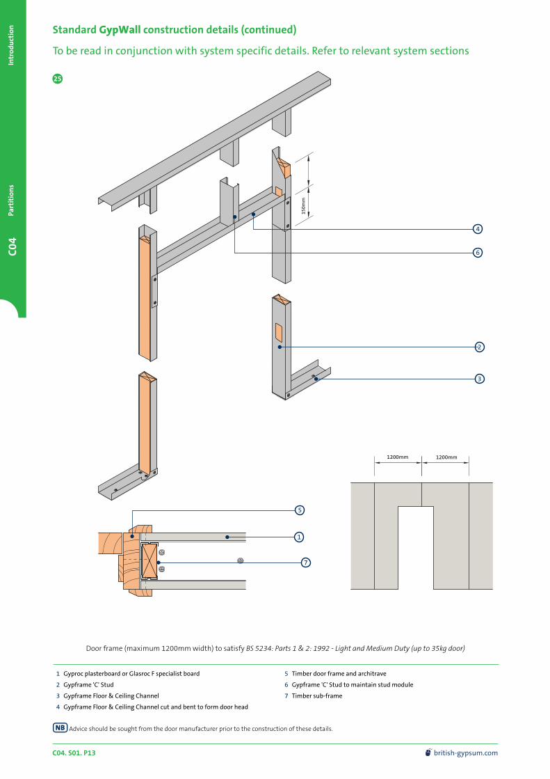
Standard GypWall construction details (continued)
To be read in conjunction with system specific details. Refer to relevant system sections
1200mm 1200mm
1 Gyproc plasterboard or Glasroc F specialist board
2 Gypframe 'C' Stud
3 Gypframe Floor & Ceiling Channel
4 Gypframe Floor & Ceiling Channel cut and bent to form door head
5 Timber door frame and architrave
6 Gypframe 'C' Stud to maintain stud module
7 Timber sub-frame
25
Door frame (maximum 1200mm width) to satisfy BS 5234: Parts 1 & 2: 1992 - Light and Medium Duty (up to 35kg door)
4
7
3
1
2
5
Advice should be sought from the door manufacturer prior to the construction of these details.
150m
m
6
C04. S01. P14 0115 945 6123 [email protected]
C04Introdu
ctionPartition
s
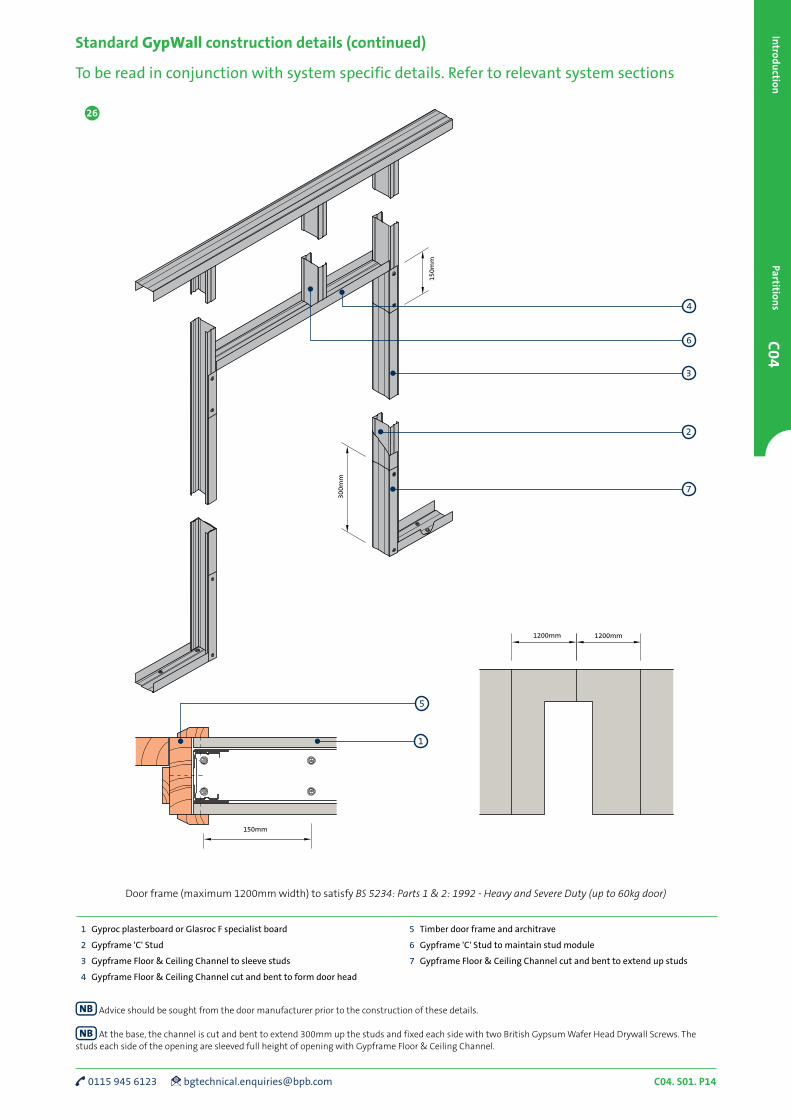
Standard GypWall construction details (continued)
To be read in conjunction with system specific details. Refer to relevant system sections
1200mm 1200mm
150mm
26
1 Gyproc plasterboard or Glasroc F specialist board
2 Gypframe 'C' Stud
3 Gypframe Floor & Ceiling Channel to sleeve studs
4 Gypframe Floor & Ceiling Channel cut and bent to form door head
5 Timber door frame and architrave
6 Gypframe 'C' Stud to maintain stud module
7 Gypframe Floor & Ceiling Channel cut and bent to extend up studs
Door frame (maximum 1200mm width) to satisfy BS 5234: Parts 1 & 2: 1992 - Heavy and Severe Duty (up to 60kg door)
4
7
1
2
5
Advice should be sought from the door manufacturer prior to the construction of these details.
At the base, the channel is cut and bent to extend 300mm up the studs and fixed each side with two British Gypsum Wafer Head Drywall Screws. The studs each side of the opening are sleeved full height of opening with Gypframe Floor & Ceiling Channel.
6
3
150m
m
300m
m

C04. S01. P15 british-gypsum.com
C04
Intr
odu
ctio
nPa
rtit
ion
s
Alternative door frame for fixed partition heads only (maximum 1200mm width) to satisfy
BS 5234: Parts 1 & 2: 1992 - Heavy and Severe Duty (up to 60kg door)
Standard GypWall construction details (continued)
To be read in conjunction with system specific details. Refer to relevant system sections
1200mm 1200mm
150mm
1200mm
150m
m
1 Gyproc plasterboard or Glasroc F specialist board
2 Gypframe 'C' Stud
3 Gypframe Floor & Ceiling Channel to sleeve studs
4 Gypframe Floor & Ceiling Channel cut and bent to form door head
5 Timber door frame and architrave
6 Gypframe 'C' Stud to maintain stud module
7 Gypframe 'C' Studs fixed back to back with British Gypsum Drywall Screws at 300mm centres staggered
8 Plasterboard infill (same type as lining) cut to fit between studs
9 Gypframe Floor & Ceiling Channel cut and bent to extend up studs
27
4
9
1
2
5
Advice should be sought from the door manufacturer prior to the construction of these details.
At the base, the channel is cut and bent to extend 300mm up the studs and fixed each side with two British Gypsum Wafer Head Drywall Screws. The studs each side of the opening are sleeved full height of opening with Gypframe Floor & Ceiling Channel.
The principle of this alternative detail is only suitable for GypWall classic, GypWall robust and GypWall extreme for fixed head situations only.
6
3
7
8
300m
m
C04. S01. P16 0115 945 6123 [email protected]
C04Introdu
ctionPartition
s
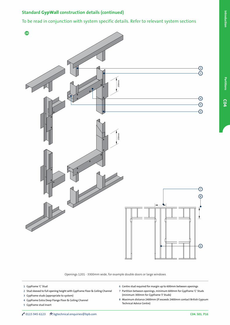
Standard GypWall construction details (continued)
To be read in conjunction with system specific details. Refer to relevant system sections
28
Openings 1201 - 3300mm wide, for example double doors or large windows
1 Gypframe 'C' Stud
2 Stud sleeved to full opening height with Gypframe Floor & Ceiling Channel
3 Gypframe studs (appropriate to system)
4 Gypframe Extra Deep Flange Floor & Ceiling Channel
5 Gypframe stud insert
6 Centre stud required for margin up to 600mm between openings
7 Partition between openings, minimum 600mm for Gypframe 'C' Studs
(minimum 300mm for Gypframe 'I' Studs)
8 Maximum distance 2400mm (if exceeds 2400mm contact British Gypsum
Technical Advice Centre)
1
3
4
150m
m15
0mm
5
2
8
7
6

C04. S01. P17 british-gypsum.com
C04
Intr
odu
ctio
nPa
rtit
ion
s
Standard GypWall construction details (continued)
To be read in conjunction with system specific details. Refer to relevant system sections
Section X - X
Section Y - Y
1 Gyproc plasterboard or Glasroc F specialist board
2 Gypframe 'C' Stud
3 Gypframe Floor & Ceiling Channel
4 Penetration seal if required (refer to damper manufacturer for details)
5 Damper (by others). Weight of damper should not exceed 57kg.
Size of damper should not exceed 1400 x 1200mm
6 Gypframe Folded Edge Standard Floor & Ceiling Channel cut and bent
to form opening head and cill
29 30
314
1
4
Opening for service penetrations in fire-rated partitions
Fire tested construction in which the damper is supported
by the partition (isometric view)
1
2
3
5
1
6
2
Elevation
X
Y
3
2
4
2
Opening up to 600mm wide for services
150m
m

C04. S01. P18 0115 945 6123 [email protected]
C04Introdu
ctionPartition
s
Standard GypWall construction details (continued)
To be read in conjunction with system specific details. Refer to relevant system sections
32
Board layout - typical configuration
33 34
Horizontal board joint - double layer Horizontal board joint - single layer
3
1 Inner layer of Gyproc plasterboard or Glasroc F specialist board
2 Outer layer of Gyproc plasterboard or Glasroc F specialist board
3 Gypframe GFS1 Fixing Strap
4 Gypframe metal framing
5 British Gypsum Drywall Screws
6 Gyproc plasterboard or Glasroc F specialist board
7 Gypframe 'C' Stud
8 Gypframe GFT1 Fixing T (alternatively use Gypframe GSF1 Fixing Strap)
2
7
8
6
7
2
5
1
3
4
C04
Gyp
Wal
l ra
pid
dB
Plu
sPa
rtit
ion
s
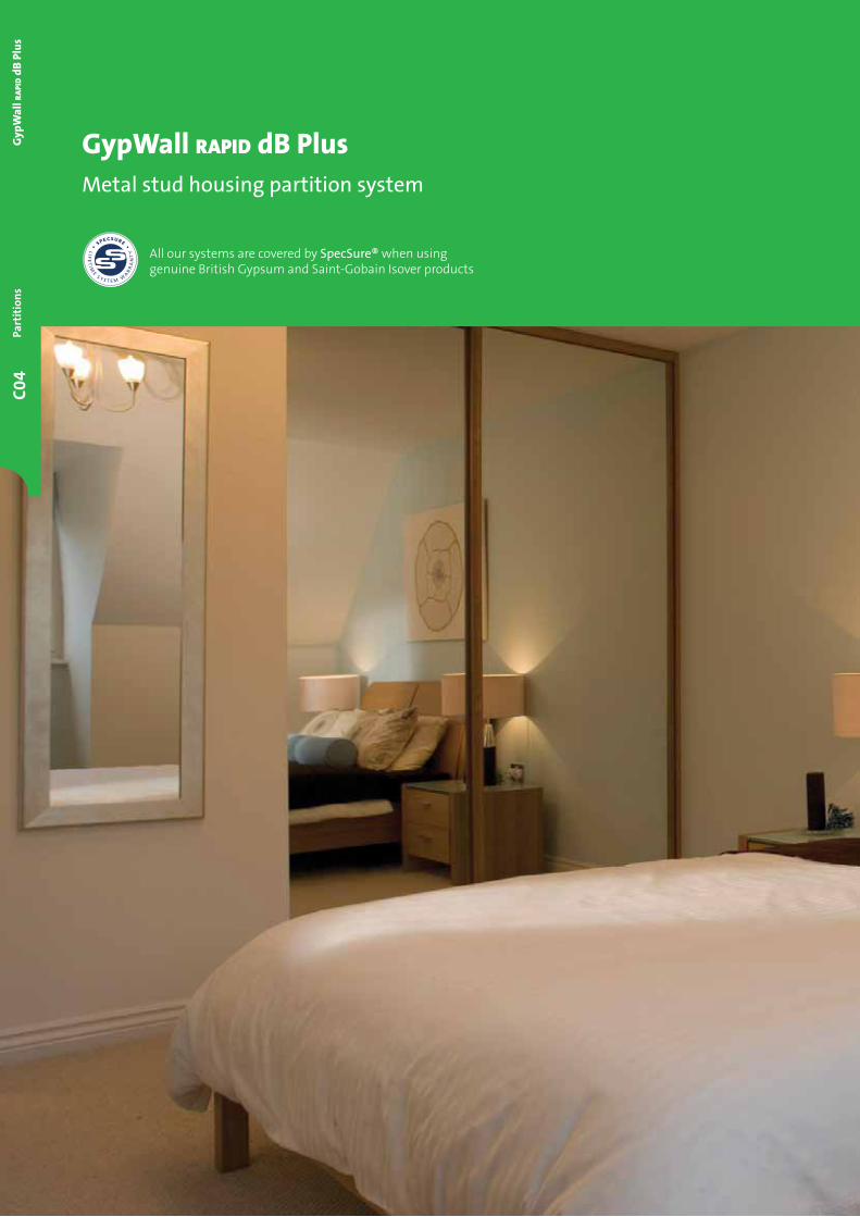
GypWall rapid dB PlusMetal stud housing partition system
All our systems are covered by SpecSure® when using genuine British Gypsum and Saint-Gobain Isover products
C04. S10. P02 0115 945 6123 [email protected]
C04G
ypWall r
apid dB
PlusPartition
s
Refer to C01. S01. P07
System can be skim finished with
Thistle PureFinish. Refer to C02. S01. P49
GypWall rapid dB Plus
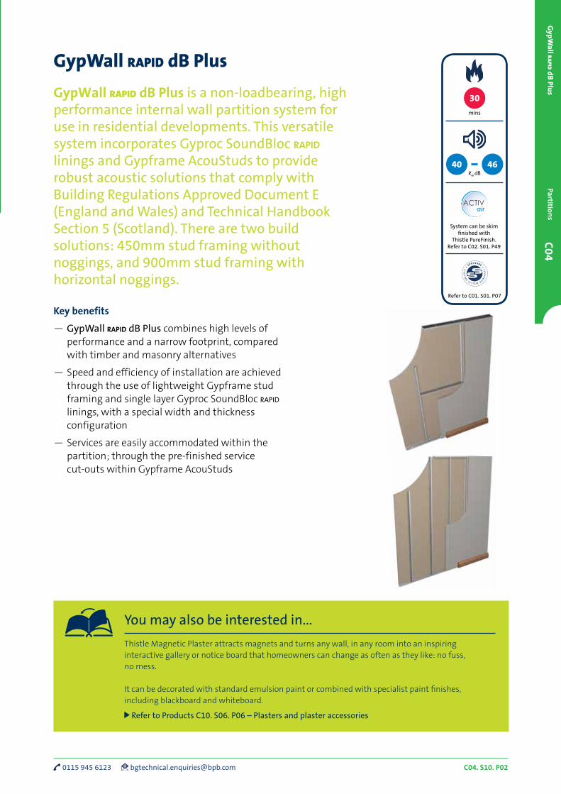
GypWall rapid dB Plus is a non-loadbearing, high performance internal wall partition system for use in residential developments. This versatile system incorporates Gyproc SoundBloc rapid linings and Gypframe AcouStuds to provide robust acoustic solutions that comply with Building Regulations Approved Document E (England and Wales) and Technical Handbook Section 5 (Scotland). There are two build solutions: 450mm stud framing without noggings, and 900mm stud framing with horizontal noggings.
Key benefits
— GypWall rapid dB Plus combines high levels of performance and a narrow footprint, compared with timber and masonry alternatives
— Speed and efficiency of installation are achieved through the use of lightweight Gypframe stud framing and single layer Gyproc SoundBloc rapid linings, with a special width and thickness configuration
— Services are easily accommodated within the partition; through the pre-finished service cut-outs within Gypframe AcouStuds
mins
30
Rw dB40 46
You may also be interested in...
Thistle Magnetic Plaster attracts magnets and turns any wall, in any room into an inspiring interactive gallery or notice board that homeowners can change as often as they like: no fuss, no mess.
It can be decorated with standard emulsion paint or combined with specialist paint finishes, including blackboard and whiteboard.
Refer to Products C10. S06. P06 – Plasters and plaster accessories

C04. S10. P03 british-gypsum.com
C04
Gyp
Wal
l ra
pid
dB
Plu
sPa
rtit
ion
s
GypWall rapid dB Plus performance
Table 1a – Solutions to satisfy the requirements of BS EN 1364-1: 1999
Detail Partition
thickness
mm
Board type1 Lining
thickness
mm
Maximum partition
height
mm
Sound insulation
Rw
dB
Duty rating Approx.
weight
kg/m²
System
reference
30 minutes fire resistance
1 75 Gyproc SoundBloc rapid 1 x 15 2400 40 Medium 27 A139A001
2 75 Gyproc SoundBloc rapid 1 x 15 2700 40 Medium 27 A139A005
5 75 Gyproc SoundBloc rapid 1 x 15 2700 43 Medium 28 A139A006
4 75 Gyproc SoundBloc rapid 1 x 15 2400 44 Medium 28 A139A003
3 102 Gyproc SoundBloc rapid 1 x 15 2700 42 Medium 28 A139A011
6 102 Gyproc SoundBloc rapid 1 x 15 2700 46 Medium 29 A139A012
For further assistance in choosing the right solution for your project, try the White Book System Selector; an online tool that enables quick and
easy filtering by performance criteria. It provides system specific information downloads including BIM (Revit) objects. Go to british-gypsum.com
1 The maximum heights quoted are limited by the fire state field of application or by limiting deflection of L/240 at 200 Pa, whichever is the more onerous.
The fire resistance and sound insulation performances are for imperforate partitions, walls and ceilings incorporating boards with all joints taped and
filled, or skimmed according to British Gypsum’s recommendations. The quoted performances are achieved only if British Gypsum and Saint-Gobain Isover
components are used throughout, and the Company’s fixing recommendations are strictly observed. Any variation in the specifications should be checked with
British Gypsum.
One layer of board each side of
Gypframe 43 AS 50 AcouStuds at 900mm centres.
43mm Gypframe GWR2 mid-height nogging.
Linings as in table.
One layer of board each side of
Gypframe 43 AS 50 AcouStuds at 450mm centres.
Linings as in table.
One layer of board each side of
Gypframe 70 AS 50 AcouStuds at 450mm centres.
Linings as in table.
One layer of board each side of
Gypframe 43 AS 50 AcouStuds at 900mm centres.
43mm Gypframe GWR2 mid-height nogging.
25mm Isover Acoustic Partition Roll (APR 1200).
Linings as in table.
One layer of board each side of
Gypframe 43 AS 50 AcouStuds at 450mm centres.
25mm Isover Acoustic Partition Roll (APR 1200).
Linings as in table.
One layer of board each side of
Gypframe 70 AS 50 AcouStuds at 450mm centres.
25mm Isover Acoustic Partition Roll (APR 1200).
Linings as in table.
1
4
2
5
3
6
For details of when
to specify fire
resistance using EN
Refer to C02. S01. P05

C04. S10. P04 0115 945 6123 [email protected]
C04G
ypWall r
apid dB
PlusPartition
s
GypWall rapid dB Plus performance (continued)
One layer of board each side of
Gypframe 43 AS 50 AcouStuds at 900mm centres.
43mm Gypframe GWR2 mid-height nogging.
Linings as in table.
One layer of board each side of
Gypframe 43 AS 50 AcouStuds at 450mm centres.
Linings as in table.
One layer of board each side of
Gypframe 70 AS 50 AcouStuds at 450mm centres.
Linings as in table.
One layer of board each side of
Gypframe 43 AS 50 AcouStuds at 900mm centres.
43mm Gypframe GWR2 mid-height nogging.
25mm Isover Acoustic Partition Roll (APR 1200).
Linings as in table.
One layer of board each side of
Gypframe 43 AS 50 AcouStuds at 450mm centres.
25mm Isover Acoustic Partition Roll (APR 1200).
Linings as in table.
One layer of board each side of
Gypframe 70 AS 50 AcouStuds at 450mm centres.
25mm Isover Acoustic Partition Roll (APR 1200).
Linings as in table.
Table 1b – Solutions to satisfy the requirements of BS 476: Part 22: 1987
Detail Partition
thickness
mm
Board type1 Lining
thickness
mm
Maximum partition
height
mm
Sound insulation
Rw
dB
Duty rating Approx.
weight
kg/m²
System
reference
30 minutes fire resistance
1 75 Gyproc SoundBloc rapid 1 x 15 2400 40 Medium 27 A139A001
2 75 Gyproc SoundBloc rapid 1 x 15 2700 40 Medium 27 A139A005
5 75 Gyproc SoundBloc rapid 1 x 15 2700 43 Medium 28 A139A006
4 75 Gyproc SoundBloc rapid 1 x 15 2400 44 Medium 28 A139A003
3 102 Gyproc SoundBloc rapid 1 x 15 2700 42 Medium 28 A139A011
6 102 Gyproc SoundBloc rapid 1 x 15 2700 46 Medium 29 A139A012
For further assistance in choosing the right solution for your project, try the White Book System Selector; an online tool that enables quick and
easy filtering by performance criteria. It provides system specific information downloads including BIM (Revit) objects. Go to british-gypsum.com
1 Based on a limiting deflection of L/240 at 200 Pa.
The fire resistance and sound insulation performances are for imperforate partitions, walls and ceilings incorporating boards with all joints taped and
filled, or skimmed according to British Gypsum’s recommendations. The quoted performances are achieved only if British Gypsum and Saint-Gobain Isover
components are used throughout, and the Company’s fixing recommendations are strictly observed. Any variation in the specifications should be checked with
British Gypsum.
1
4
2
5
3
6
For details of when
to specify fire
resistance using BS
Refer to C02. S01. P05
C04. S10. P05 british-gypsum.com
C04
Gyp
Wal
l ra
pid
dB
Plu
sPa
rtit
ion
s
GypWall rapid dB Plus design
Building design
There are two build solutions; 450mm stud framing without
noggings, and 900mm stud framing with horizontal noggings.
Planning – key factors
The position of services should be pre-determined and their
installation planned into the frame erection stage.
Partition to structural steelwork junctions
When designing the layout of rooms requiring separation by sound
insulating walls abutting structural steelwork, consideration should
be given to the potential loss of sound insulation performance
through the steelwork.
Refer to C02. S01. P10 – Building acoustics.
Cavity fire barriers
Gyproc SoundBloc rapid screw-fixed into the web of perimeter
channels or vertical studs will provide a satisfactory closure to
flame and smoke.
Refer to C06. S07. P02 – Cavity fire barriers.
Services
Electrical
The installation of electrical services should be carried out in
accordance with BS 7671. The cut-outs in the studs can be used
for routing electrical and other small services (Refer to Partitions
introduction C04. S01. P07 – construction detail 2a). Switch boxes
and socket outlets can be supported from Gypframe 99 FC 50 Fixing
Channel fixed horizontally between studs, or a high performance
socket box detail used where higher acoustic performance is
required.
Cables should be protected by conduit, or other suitable
precautions taken to prevent abrasion when they pass through
the metal frame. Service cut-outs should be aligned to allow easy
installation of service. If studs require cutting, cut from the same
end of each stud to ensure cut-out alignment.
Heating pipes
Where heating pipes, particularly micro-bore systems, are to be
located within the partition, it is recommended that only one pipe
is passed through each aperture in the metal framework. If this
cannot be accommodated for whatever reason, it may then be
necessary to incorporate proprietary pipe restraining clips or other
means of keeping the pipes apart to prevent vibration noise.
Ducts
Where a large number of electrical cables or pipes have to be
accommodated, a service duct can be created by closing up the stud
centres to 450mm and omitting the intermediate nogging.
Electrical cables should be attached using an appropriate cable
retaining device in order to satisfy the requirements of BS 7671.
Fixtures
Lightweight fixtures can be made directly to the partition linings.
Medium weight fixtures can be made to Gypframe 99 FC 50 Fixing
Channel. Heavyweight fixtures (to BS 5234), such as wash basins
and wall cupboards, can be fixed using plywood secured with
Gypframe Service Support Plate.
Refer to C02. S01. P33 – Service installations.
Board finishing
Refer to C08. S01. P02 – Finishes.
Tiling
Tiles can be applied to the surface of lightweight partition systems.
Refer to C08. S04. P02 – Tiling.
In intermittently wet use areas, such as around baths, Gyproc SoundBloc rapid mr should be used in accordance with NHBC recommendations. Two coats of Gyproc Drywall Sealer applied to the face of standard grade plasterboards, with the edges adequately protected from moisture may also be suitable to receive a tile finish. The application of Gyproc Drywall Sealer provides surface water absorption resistance only, and does not meet the performance requirements for moisture resistant grade boards as defined in BS EN 520, type H1.
SpecSure®
All our systems are covered by SpecSure® when using genuine British Gypsum and Saint-Gobain Isover products.
C04. S10. P06 0115 945 6123 [email protected]
C04G
ypWall r
apid dB
PlusPartition
s
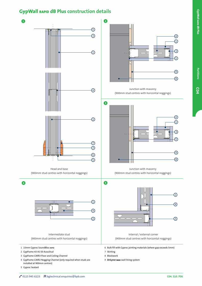
Intermediate stud
(900mm stud centres with horizontal noggings)
Junction with masonry
(900mm stud centres with horizontal noggings)
GypWall rapid dB Plus construction details
1 15mm Gyproc SoundBloc rapid
2 Gypframe 43 AS 50 AcouStud
3 Gypframe GWR3 Floor and Ceiling Channel
4 Gypframe GWR2 Nogging Channel (only required when studs are
installed at 900mm centres)
5 Gyproc Sealant
6 Bulk fill with Gyproc jointing materials (where gap exceeds 5mm)
7 Skirting
8 Blockwork
9 DriLyner basic wall lining system
1
3
9
5
5
1 2
Head and base
(900mm stud centres with horizontal noggings)
Junction with masonry
(900mm stud centres with horizontal noggings)
Internal / external corner
(900mm stud centres with horizontal noggings)
5
3
1
2
4
7
3
6
5
1
4
2
1
4
3
8
1
3
9
8
3
4 5
4
4

C04. S10. P07 british-gypsum.com
C04
Gyp
Wal
l ra
pid
dB
Plu
sPa
rtit
ion
s
GypWall rapid dB Plus construction details (continued)
1 15mm Gyproc SoundBloc rapid
2 Gypframe 43 AS 50 AcouStud
3 Gypframe GWR3 Floor and Ceiling Channel
4 Gypframe GWR2 Nogging Channel (only required when studs are
installed at 900mm centres)
5 Gypframe GA6 Splayed Angle
6 Additional framing
7 Wash basin
8 Gyproc Sealant
5
81
4
6 7
1
4
3
3
4
6
7
5
1
Framing intersection
(900mm stud centres with horizontal noggings)
Splayed angle
(900mm stud centres with horizontal noggings)
‘T’ junction
(900mm stud centres with horizontal noggings)
2
2
4
Additional framing for heavy fixtures
Wall abutment
(900mm stud centres with horizontal noggings)
6
8 9
10
C04. S10. P08 0115 945 6123 [email protected]
C04G
ypWall r
apid dB
PlusPartition
s
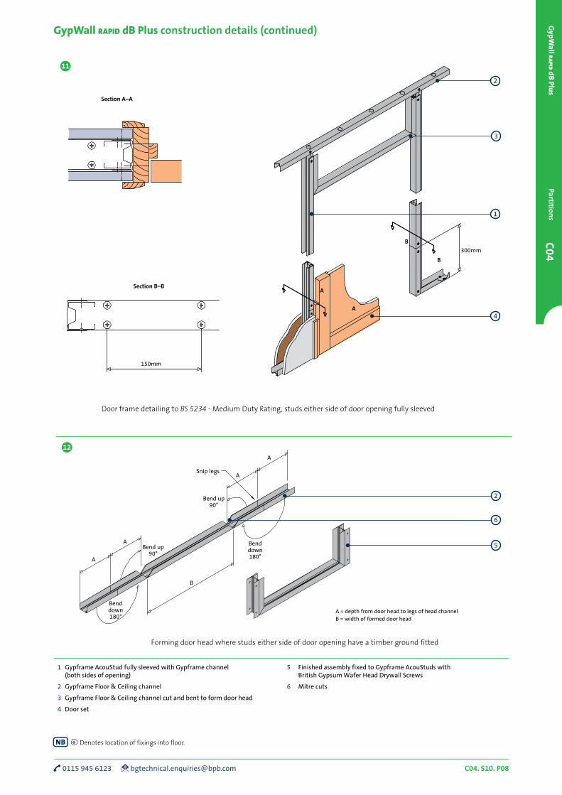
150mm
Section A–A
Section B–B
300mm
B
B
A
A
1 Gypframe AcouStud fully sleeved with Gypframe channel (both sides of opening)
2 Gypframe Floor & Ceiling channel
3 Gypframe Floor & Ceiling channel cut and bent to form door head
4 Door set
5 Finished assembly fixed to Gypframe AcouStuds with British Gypsum Wafer Head Drywall Screws
6 Mitre cuts
A = depth from door head to legs of head channelB = width of formed door head
Snip legs
Bend up 90°
B
A
ABend up
90°
Bend down 180°
Bend down 180°
A
A
11
12
GypWall rapid dB Plus construction details (continued)
2
3
2
Door frame detailing to BS 5234 - Medium Duty Rating, studs either side of door opening fully sleeved
Forming door head where studs either side of door opening have a timber ground fitted
Denotes location of fixings into floor.
1
4
6
5
C04. S10. P09 british-gypsum.com
C04
Gyp
Wal
l ra
pid
dB
Plu
sPa
rtit
ion
s
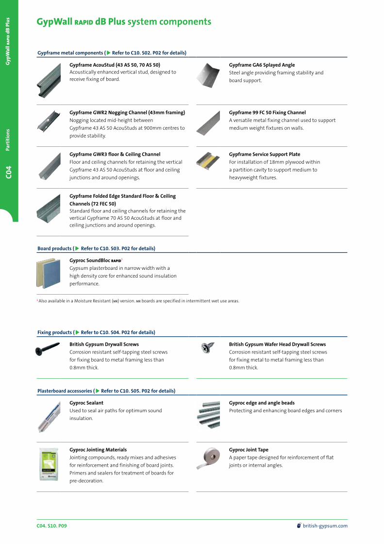
GypWall rapid dB Plus system components
Gypframe metal components ( Refer to C10. S02. P02 for details)
Gypframe AcouStud (43 AS 50, 70 AS 50)Acoustically enhanced vertical stud, designed to receive fixing of board.
Gypframe GA6 Splayed Angle
Steel angle providing framing stability and
board support.
Gypframe GWR2 Nogging Channel (43mm framing)
Nogging located mid-height between
Gypframe 43 AS 50 AcouStuds at 900mm centres to
provide stability.
Gypframe 99 FC 50 Fixing Channel
A versatile metal fixing channel used to support
medium weight fixtures on walls.
Gypframe GWR3 floor & Ceiling Channel
Floor and ceiling channels for retaining the vertical
Gypframe 43 AS 50 AcouStuds at floor and ceiling
junctions and around openings.
Gypframe Service Support Plate
For installation of 18mm plywood within
a partition cavity to support medium to
heavyweight fixtures.
Gypframe Folded Edge Standard Floor & Ceiling
Channels (72 FEC 50)Standard floor and ceiling channels for retaining the vertical Gypframe 70 AS 50 AcouStuds at floor and ceiling junctions and around openings.
Board products ( Refer to C10. S03. P02 for details)
Gyproc SoundBloc rapid1
Gypsum plasterboard in narrow width with a
high density core for enhanced sound insulation
performance.
Fixing products ( Refer to C10. S04. P02 for details)
British Gypsum Drywall Screws
Corrosion resistant self-tapping steel screws
for fixing board to metal framing less than
0.8mm thick.
British Gypsum Wafer Head Drywall Screws
Corrosion resistant self-tapping steel screws
for fixing metal to metal framing less than
0.8mm thick.
Plasterboard accessories ( Refer to C10. S05. P02 for details)
Gyproc Sealant
Used to seal air paths for optimum sound
insulation.
Gyproc edge and angle beads
Protecting and enhancing board edges and corners
Gyproc Jointing Materials
Jointing compounds, ready mixes and adhesives
for reinforcement and finishing of board joints.
Primers and sealers for treatment of boards for
pre-decoration.
Gyproc Joint Tape
A paper tape designed for reinforcement of flat
joints or internal angles.
1 Also available in a Moisture Resistant (mr) version. mr boards are specified in intermittent wet use areas.
C04. S10. P10 0115 945 6123 [email protected]
C04G
ypWall r
apid dB
PlusPartition
s
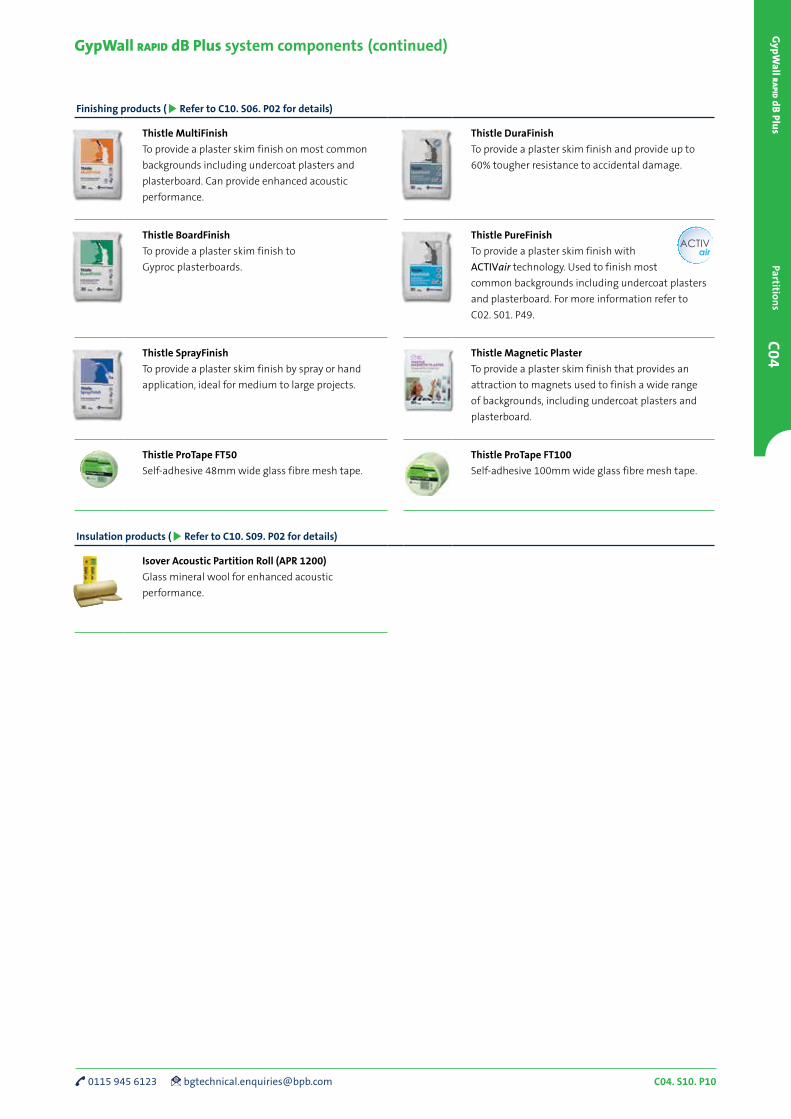
GypWall rapid dB Plus system components (continued)
Finishing products ( Refer to C10. S06. P02 for details)
Thistle MultiFinish
To provide a plaster skim finish on most common
backgrounds including undercoat plasters and
plasterboard. Can provide enhanced acoustic
performance.
Thistle DuraFinish
To provide a plaster skim finish and provide up to
60% tougher resistance to accidental damage.
Thistle BoardFinish
To provide a plaster skim finish to
Gyproc plasterboards.
Thistle PureFinish
To provide a plaster skim finish with
ACTIVair technology. Used to finish most
common backgrounds including undercoat plasters
and plasterboard. For more information refer to
C02. S01. P49.
Thistle SprayFinish
To provide a plaster skim finish by spray or hand
application, ideal for medium to large projects.
Thistle Magnetic Plaster
To provide a plaster skim finish that provides an
attraction to magnets used to finish a wide range
of backgrounds, including undercoat plasters and
plasterboard.
Thistle ProTape FT50
Self-adhesive 48mm wide glass fibre mesh tape.
Thistle ProTape FT100
Self-adhesive 100mm wide glass fibre mesh tape.
Insulation products ( Refer to C10. S09. P02 for details)
Isover Acoustic Partition Roll (APR 1200)
Glass mineral wool for enhanced acoustic
performance.

C04. S10. P11 british-gypsum.com
C04
Gyp
Wal
l ra
pid
dB
Plu
sPa
rtit
ion
s
GypWall rapid dB Plus system installation overview
This is intended to be a basic description of how the system is installed.
For installation guidance refer to the British Gypsum Site Book.
Additional information
For full installation details, refer to the British Gypsum Site Book, available to download from british-gypsum.com
Gypframe AcouStuds can be friction-fitted
vertically at 450mm centres to form the
framework,
Isover Acoustic Partition Roll (APR 1200)
can also be added to the partition cavity for
increased acoustic performance.
Gyproc SoundBloc rapid boards are
screw-fixed to all framing members with
British Gypsum Drywall Screws to form
the lining.
Gypframe Floor & Ceiling Channels are
suitably fixed to the floor and soffit.
Gypframe Floor & Ceiling Channels are
suitably fixed to abutments to form the
perimeter framework.
The perimeter of the partition is sealed on
both sides with Gyproc Sealant.
or Gypframe AcouStuds can be friction-
fitted vertically at 900mm centres to form
the framework.
Where Gypframe stud framing is installed at
900mm centres, Gypframe GWR2 Nogging
Channels are located horizontally between
each pair of studs at mid-height. Additional
framing is installed as required to support
heavy fixtures.