Gypsum Technical Manual · 2018-09-07 · The range of plaster compounds, when applied to...
96
Technical Manual Gypsum
Transcript of Gypsum Technical Manual · 2018-09-07 · The range of plaster compounds, when applied to...

Technical ManualGypsum

Index
Inde
x1 Marley Building Systems Gypsum Ceilings & Partitioning Product Range:
2 Introduction to SIniat Plasterboard:
Plasterboard Properties TechnicalSpecificationandMaterialSafety ProductRangeIdentification • SIniat Standard Plasterboard • SIniat Technical Plasterboard • SIniat Fire Check Plasterboard •SIniatMoistureCheckPlasterboard Building with Plasterboard Profile 1.1PerformanceSpecifications/Properties •SoundInsulationPerformance(Acoustics) •DescriptionofCommonTermsusedwhendescribingsound InsulationPerformance •EffectofDifferentWallsonSoundInsulationPerformance • Fire Resistance • Evaluation Criteria •ModificationstoFireRatedsystems • Fire Hazard Properties 1.2ContextualApplicationandprotection • Condensation and Ventilation •ExternalApplications •ExposuretoHighHumidity • Exposure to Excessive Heat 1.3Storage,DeliveryandHandling •HandlingofSIniatPlasterboard •CuttingofSIniatPlasterboard • Setting Out and Installation •EnvironmentalControl •AccessoriesandSpacings 1.4 SIniat Plasterboard Finishing Guide •SurfacePreparation •GeneralRecommendations •JointingofPlasterboardTaperedEdges • Checklist •TypicalLightConditionsandFinishingLevels
3 SIniat Fixed Partition Systems:
InternalPartitionSystems Plasterboard Jointing TypicalLocatingofStuds TypicalPartitionLayout TypicalstudLocationatDoorOpenings TypicalPartitionCornerDetails TypicaldoorTrackLocationonCorners TypicalDoorFrameDetails Typical“T”JunctionDetails StandardSpecificationsforDrywallSystemsupto3600mm PlasterboardPartitionfrom3600mmto8000mminHeight PlasterboardPartitionover8000mminHeight SIniat89mmPartitionSystem3DDoorDetail ProtectionofLiftandVentShafts CurvedWalls SIniatDoorFrameKit SIniatWindowFrameKit SIniatFixedPartitionAluminiumTrimAccessories TechnicalSpecification TypicalResidentialWallDivisions
99991010101111
11-1212
12-13
13-14141415151616161717171818
18-1919-20
202020212122
22-23
2424242525252626
26-2728-3536-3737-39
4041424344
45-4849-5252-55
4-8

Inde
xIndex
55-5758
59-606161
62626263636363
63-6464-65
6666-67
696970
70-72737475
76-79798081
81-82838384848484868686
87-9090-92
9293-95
WetAreaSpecification ConstructionDetailsforWetAreas Fixtures and Fittings Plasterboard Fitting and Fixing Details CurvedWall
4 SIniat Ceiling Systems:
MastergridLayoutDetails StandardSpecificationsforCeilings GridLayoutforSuspendedCeilingsusing1200mmCrossT-Section TypicalSuspensionDetails •SuspensionDetailsforExposedCeilingGrid •GridLayoutforSuspendedCeilingsusing600mmCrossT-Section •SubGridDetail(StrainedWire)ExposedCeiling •Lay-inSuspendedCeiling •SIniatMastergridSuspendedCeiling •RecommendationfortheSuspensionofTeeSystems •InstallationoftheExposedGridSystem •SIniatLay-inCeilingGridSystem •GridLayoutforLay-inCeilingsSubGridDetail CeilingTrimDetails SIniat Ceiling Tiles •PaintedandPerforatedCeilingTiles TimberBrandering Steel Brandering SIniat75mmCorniceDetail GridLayoutforPlasterboardCeilingsusing1200mmCrossT-Section Suspended Plaster Grid •SiniatPlasterGridSystem(SiniatMastergrid) AluminiumSections GridLayoutforCeilingsSubGridDetail SIniatMainsuspensionMethodsforCeilingGrid 9mmand12mmFlushPlasteredCeiling Curve Ceilings FireRatedCeilingSystems FireRatedSuspendedCeilingSystems FixedFireRatedSystems 75mmSiniatCoveCorniceDetailforFirePropertySpecification GridLayoutFireResistancePlasteredCeiling SIniat XPS Decor Cornices FixingInstructionsforCornices PreparingJointsandCornerMitreofCornices Opening Solutions
4
Introduction
Intr
odu
ctio
nMarleyBuildingSystemsispartofETEX,aBelgianIndustrialgroupthatmanufacturesandmarketshighqualitybuildingmaterialsandsystems.
Westrivetobetheleaderinsustainableandaffordablebuildingsolutions.Tomeettheseneedsandanticipatenewtrends,wehavedevelopedastrategybasedonourfourcorebusinesses:claddingandbuildingboardsinfibrecementandplaster,roofingmaterials,passivefireprotectionandhighperformanceinsulation.Thishasearnedusaplaceinthemarketasaleadingsupplierofhighqualityandaffordableroofing,claddingandconstruction products.
TogetherwithMarleyRoofing’s60yearindustryexperienceweaimtonotonlysupplyproductsandservicesthatredefinebuildingmethodology,butalsogivecompletepeaceofmind.
MarleyBuildingSystems’productportfolioincludesalltypesofconcreteandclaytiles,fibrecementslates,profiledroofsheeting,fibrecementandgypsumbasedcladdingsolutionsanddecorativefaçades.
Withover100years’experience,wehaveindustryknowledgethatissecondtononeandcanofferourcustomerscompleteconfidenceintheproductsandservicesweprovide.MarleyBuildingSystems’marketleadingproductsdeliveracombinationofeco-friendlymaterialsandsurpassesallperformancedemands.
MarleyBuildingSystemsSouthAfrica44IndustryRoadOliefantsfonteinTelephone:(011)3894500|Fax:(011)8646816
4

5
Pro
duct
Ran
ge
Marley Building Systems Gypsum Ceilings & Partitioning Product Range
MarleyBuildingSystemsoffersacomprehensiverangeofplasterboardsystemstomeetthepracticalandperformanceneedsofnewbuildandrefurbishmentprojects,coveringallsectorsofthemarket,residential,commercial,retail,hospitality&health.ThecomprehensiverangeofsystemsisdesignedtooffertheArchitect,DeveloperandSpecifierthepossibilityoftranslatingexcitingvisualconceptsintoactualon-sitereality.
Standardplasterboards6.4mm square edge• 2400x900-2400x1200• 2700x900-2700x1200• 3000x900-3000x1200• 3300x900-3300x1200• 3600x900-3600x1200• 4200x900-4200x12009mm tapered edge• 2400x1200• 2700x1200• 3000x1200• 3300x1200• 3600x120012mm tapered edge• 1200x2400,2700,3000, 3300,360015mm tapered edge• 1200x2700,3000,3600
TechnicalPlasterboards12,5mm & 15mm FirecheckTapered edge• 2400x1200• 2700x1200• 3000x1200• 3600x120012,5mm & 15mm MoistureCheck Tapered edge• 2700x1200• 3000x1200• 3600x1200
Siniatplasterboards
Construction practice and BuildingRegulationscallforarangeofboardstomatchspecificinstallationneeds.
SIniat plasterboards are complementedbyhighperformanceproductsspecificallydesignedforfireresistance,moistureresistance, acoustic applications and provide thermalandvapourresistancewhenusedinconjunctionwithothercomplementaryproduct.
SIniatplasterboardscarrytheSANS266–2003standardsmark.
SIniatplasterboardssystemsaretestedforfireresistancetoSANS10177Part2–2005forstability,integrityandinsulation.
SiniatplasterboardscarryGreenTaglevelBcertification.
SIniat Partition &metal system sections
MarleyBuildingSystemshasdevelopedacompleterangeofmetalsystemsforuseincombinationwithitsplasterboardsandaccessoryproducts.Togethertheyprovidesolutionstomeetallthedesignrequirementsofamodernconstructionmarket.
Tocomplementitsrangeofplasterboardpartitions,ceilings,andplasters,MarleyBuildingSystemsoffersspecialist accessories such as aluminiumtrimsystems,doorandwindowframekits,accesspanelsandfixings.
SIniat Studs
• 51mm• 58mm• 63.5mm• 102mm
SIniat Track
• 52mm• 59mm• 65mm• 102mm• 103mm
Lengths 0f 3000mm
Lengths:2100,2400,2700,3000,3600,4200Orcanbemadetorequiredlengthmax8m
64,00
35,0
0
65,0 0
24,0
0
Plasterboard Types
5
6
Pro
duct
Ran
ge
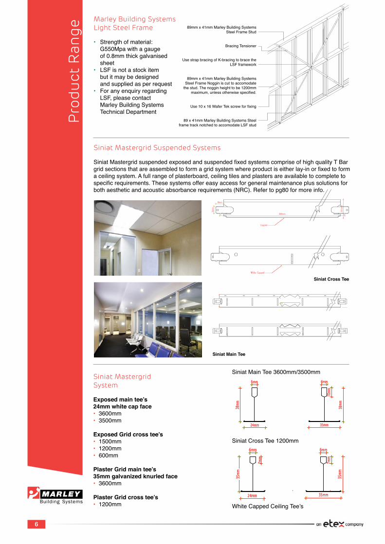
Siniat Mastergrid Suspended Systems
SiniatMastergridsuspendedexposedandsuspendedfixedsystemscompriseofhighqualityTBargridsectionsthatareassembledtoformagridsystemwhereproductiseitherlay-inorfixedtoformaceilingsystem.Afullrangeofplasterboard,ceilingtilesandplastersareavailabletocompletetospecificrequirements.Thesesystemsoffereasyaccessforgeneralmaintenanceplussolutionsforbothaestheticandacousticabsorbancerequirements(NRC).Refertopg80formoreinfo.
Siniat MastergridSystem
Exposed main tee’s24mm white cap face• 3600mm• 3500mm
Exposed Grid cross tee’s• 1500mm• 1200mm• 600mm
Plaster Grid main tee’s35mm galvanized knurled face• 3600mm
Plaster Grid cross tee’s• 1200mm
Siniat Cross Tee
Siniat Main Tee
SiniatMainTee3600mm/3500mm
SiniatCrossTee1200mm
WhiteCappedCeilingTee’s
Marley Building SystemsLight Steel Frame
• Strengthofmaterial: G550Mpawithagauge of0.8mmthickgalvanised sheet• LSFisnotastockitem butitmaybedesigned andsuppliedasperrequest• Foranyenquiryregarding LSF,pleasecontact MarleyBuildingSystems TechnicalDepartment
89mmx41mmMarleyBuildingSystemsSteelFrameStud
Bracing Tensioner
UsestrapbracingofK-bracingtobracetheLSFframework
89mmx41mmMarleyBuildingSystemsSteelFrameNogginiscuttoaccomodatethestud.Thenogginheighttobe1200mm
maximum,unlessotherwisespecified.
Use10x16WaferTekscrewforfixing
89x41mmMarleyBuildingSystemsSteelframetracknotchedtoaccomodateLSFstud
6
7
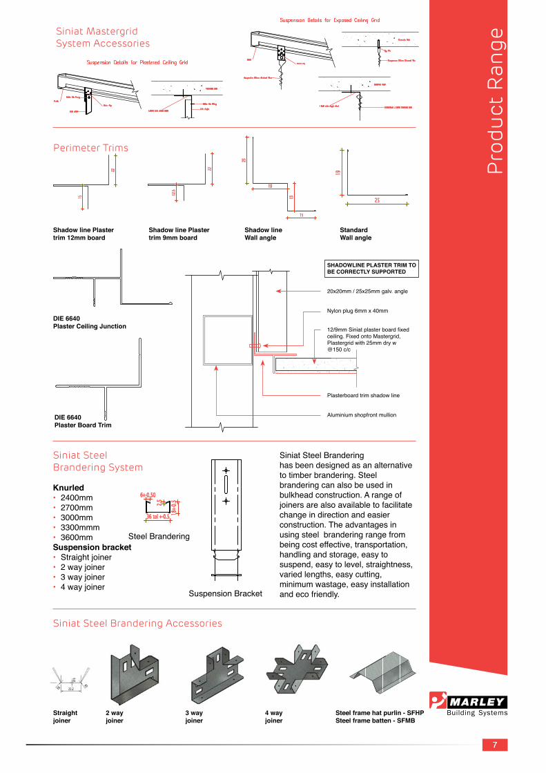
Siniat MastergridSystem Accessories
Siniat Steel Branderinghas been designed as an alternative totimberbrandering.Steelbrandering can also be used in bulkheadconstruction.Arangeofjoinersarealsoavailabletofacilitatechange in direction and easier construction. The advantages in usingsteelbranderingrangefrombeingcosteffective,transportation,handlingandstorage,easytosuspend,easytolevel,straightness,variedlengths,easycutting,minimumwastage,easyinstallationandecofriendly.
Siniat SteelBrandering System
Knurled• 2400mm• 2700mm• 3000mm• 3300mmm• 3600mmSuspension bracket• Straightjoiner• 2wayjoiner• 3wayjoiner• 4wayjoiner
Siniat Steel Brandering Accessories
Shadow line Plastertrim 12mm board
Shadow line Plastertrim 9mm board
Shadow lineWall angle
StandardWall angle
Straightjoiner
2 wayjoiner
3 wayjoiner
4 wayjoiner
DIE 6640Plaster Ceiling Junction
DIE 6640Plaster Board Trim
Suspension Bracket
Perimeter Trims
Pro
duct
Ran
ge
SHADOWLINE PLASTER TRIM TO BE CORRECTLY SUPPORTED
20x20mm/25x25mmgalv.angle
12/9mmSiniatplasterboardfixedceiling.FixedontoMastergrid,Plastergridwith25mmdryw@150c/c
Nylonplug6mmx40mm
Plasterboardtrimshadowline
Aluminiumshopfrontmullion
Steel frame hat purlin - SFHPSteel frame batten - SFMB
Steel Brandering
7
8
Pro
duct
Ran
ge
Plasterboardisfinishedusingplastercompounds,whereeitherafinalfloatfinishorsandingisundertakenandthenfinallypaintedtoachieveasmoothandevenappearance.
Nobuildingliningsystemhasasurfacethatisperfectlyflatandtotallyfreeofimperfections.Bypayingattentiontoframing,plasterboard sheet orientation, paintfinishesandlightingconditions, it is possible to attain theperceptionofflatness.Therangeofplastercompounds,whenappliedtospecificationwillassistinachievingthefinishesasspecified.
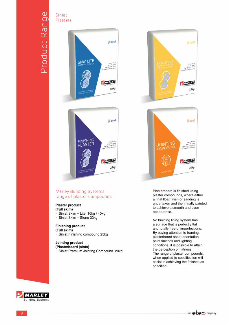
Marley Building Systemsrange of plaster compounds
Plaster product(Full skim)• SiniatSkim–Lite10kg/40kg• SiniatSkim–Stone33kg
Finishing product(Full skim)• SiniatFinishingcompound25kg
Jointing product(Plasterboard joints)• SiniatPremiumJointingCompound20kg
SiniatPlasters
8
9
Introduction to Siniat Plasterboard
Introduction to Siniat Plasterboard
Product Range
Plasterboard properties
Plasterboardconsistsofacorethatismadefromgypsum,anaturallyoccurringmaterial.Thelinerpaperusedtomakethisproductisbiodegradableandmadefrom100%recycledpaper.Hence,theenvironmentalbenefitofPlasterboardisthatitis100%recyclable.
The plasterboard manufacturing process operates under strict environmental guidelines, adhering to and encompassing the following:• Efficientuseofenergyandwater• Efficientcollectionandmonitoringofdust• Ongoing waste reduction• Minimisationofplantimpactonsurroundings
Technical Specification & Material Safety:
Standardplasterboardisnotclassifiedashazardousastheproductisnon-toxicandNon-flammable.MaterialSafetyDataSheetsareavailableonrequestfromourTechnicalDepartment.
TheSiniatPlasterboardrangeisSABSApprovedunderspecificationSANS266
PRODUCT RANGE IDENTIFICATION
• Siniat Standard Plasterboard
SiniatStandardPlasterboardisidentifiedbytheivoryfaceandbrown backingpaperliners,withnospecialadditivestothegypsumcoreor specialtreatmenttothepaperlinersexceptthatwiththe6,4/9/12/15mm plasterboard,fibreglassstrandshavebeenaddedtothecoretoallow forgreaterstrengthandflexibility.Thisproductisusedfordomesticand commercialceilingapplicationsaswellaspartitioningapplicationsto SABISAspec.Siniat Standard Plaster board is also used to create bulkheads,curvedceilingsandcurvedwalls.6.4mmSiniat Standard Plasterboardissuitableforbranderingceilings,andmaybeusedfor plasterboardceilingapplicationstoSABISAspecificationsatamax.of 300mmcentersandplasteringnotexceeding6mm.
Indt
rodu
ctio
n
9
10
Introduction to Siniat Plasterboard
• Siniat Technical Plasterboard:
TheSiniatTechnicalPlasterboardcompositionismanufacturedto enhanceandmeetparticularenvironmentalspecificdesign,performance andutilitarianrequirements.MarleyBuildingSystemsmanufacturerstwo typesoftechnicalplasterboards,namely:
• Siniat Fire Check Plasterboard:
The SiniatFireCheckPlasterboardhasexfoliatedvermiculiteand fibreglassstrandsinthegypsumcoretoincreasefireresistance.Itis differentiatedbyitscoveringofpinkpaperliner.Availablein12,5mm and15mmthicknessesandisrecommendedforareaswhereadditional fireresistanceisrequired,e.g.:fireratedwalls,fireratedceilings, protectionofloadbearingstructures,firebreaks,occupancyseparating walls, division separating walls, etc.
• Siniat Moisture Check Plasterboard:
SiniatMoistureCheckPlasterboardhassiliconeinthegypsumcore andissuitableforusein‘wetareas”showers,bathrooms,kitchensand protected external applications. SiniatMoistureCheck12.5mmand 15mmPlasterboardcanbeusedinareaswhereceramicwalltilingis required.Thisplasterboardisnotsuitableforprotectionagainst continuousdampnessorasabaseforcementrendering.Moisture Check Plasterboards are lined on both sides with a distinctive green waterrepellentpaperforeaseofidentification.Theboardsarenot suitableforuseintemperaturesabove52°C,andmustnotbesubjected tofreezingtemperatureswithoutriskofdamage.
MoistureCheckPlasterboardisrecommendedforbathroomand kitchenapplicationswheretheaircancontainhighlevelsofwatervapour intermittently.
Sin
iat
Pla
ster
boar
d
10

11
Introduction to Siniat Plasterboard
Building with Plasterboard
ThecomprehensiverangeofSiniatPlasterboard‘specificsystems’meetboththepracticalandperformanceneedsofbothnewandrefurbishmentprojects,rangingfrombasictohigh-endsystems.
Profile
The6.4mmSiniatPlasterboardismanufacturedwithasquareedgeonly.TheSiniat9mm,12mm/12.5mmand15mmPlasterboardsaremanufacturedwitha taper edge.
The12mm/12.5mmand15mmboardscanbemanufacturedwithasquareedgeifrequired,butisdependentonordervolume.EnquirefromSalesbeforehand.
TaperedgesonthelongendsofPlasterboardareprovidedtoensurethatjointingcanbeachievedeasilywithasmoothandlevelfinish.
1.1 Performance Specifications / Properties
• Dimensional Stability:
Plasterboardisdimensionallystablewhencomparedtootherbuildingmaterials.Twomeasuresofdimensionalstabilityarelistedbelow: • Thermalcoefficientoflinearexpansion(α)=16.7x10⁻⁶/°C,measured unrestrainedoverthetemperaturerangeof3 °C - 32 °C • Hygralcoefficientofexpansion=6.5x10⁻⁶/mm/m,measured unrestrainedovertheRelativeHumidity(RH)rangeof10%-90% • Siniatceilingtilesarestableinmoistconditionsupto90%R.H. Typicalsaggingcanbeexpectedundertheseconditionsisasfollows: 600mmx600mmx9mmCeilingTiles-0.75mm 1200mmx600mmx9mmVinylCeilingTiles-3.95mm 1200mmx600mx12mmVinylCeilingTiles-2.95mm
• Thermal Properties:
Thermalconductivity(K-value)isthemeasureofamaterial’sabilitytotransmitheat;itisexpressedasheatflowinwattspersquaremetreofsurfaceareaforatemperaturedifferenceof1°CpermetrethicknessandisexpressedasW/m.˚CorW/m.K
Thermalcoefficientoflinearexpansion(a)=16.7x10⁻⁶/°C,measuredunrestrainedoverthetemperaturerangeof3°C-32°C
Hygralcoefficientofexpansion=6.5x10⁻⁶mm/m,measuredunrestrainedovertheRelativeHumidity(RH)rangeof10%-90%
Sin
iat
Pla
ster
boar
d
11
12
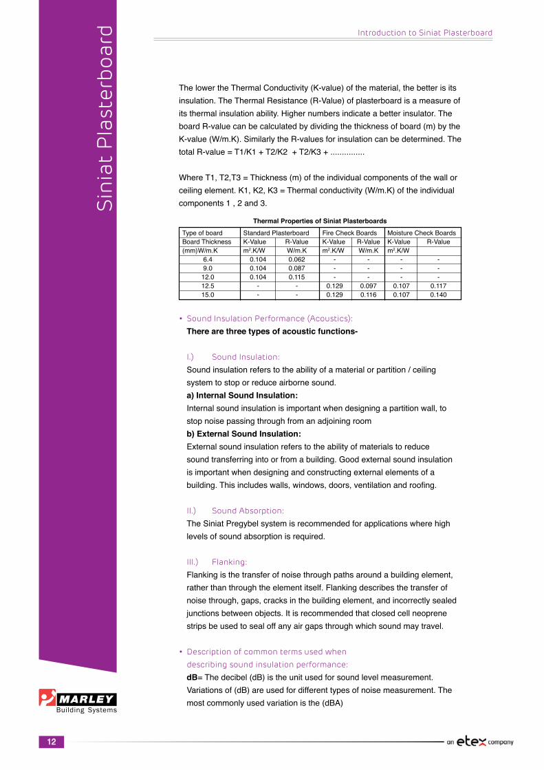
ThelowertheThermalConductivity(K-value)ofthematerial,thebetterisitsinsulation.TheThermalResistance(R-Value)ofplasterboardisameasureofitsthermalinsulationability.Highernumbersindicateabetterinsulator.TheboardR-valuecanbecalculatedbydividingthethicknessofboard(m)bytheK-value(W/m.K).SimilarlytheR-valuesforinsulationcanbedetermined.ThetotalR-value=T1/K1+T2/K2+T2/K3+...............
WhereT1,T2,T3=Thickness(m)oftheindividualcomponentsofthewallorceilingelement.K1,K2,K3=Thermalconductivity(W/m.K)oftheindividualcomponents1,2and3.
• Sound Insulation Performance (Acoustics):
There are three types of acoustic functions-
I.) Sound Insulation:
Soundinsulationreferstotheabilityofamaterialorpartition/ceiling systemtostoporreduceairbornesound. a) Internal Sound Insulation: Internalsoundinsulationisimportantwhendesigningapartitionwall,to stopnoisepassingthroughfromanadjoiningroom b) External Sound Insulation: Externalsoundinsulationreferstotheabilityofmaterialstoreduce soundtransferringintoorfromabuilding.Goodexternalsoundinsulation isimportantwhendesigningandconstructingexternalelementsofa building.Thisincludeswalls,windows,doors,ventilationandroofing.
II.) Sound Absorption:
TheSiniatPregybelsystemisrecommendedforapplicationswherehigh levelsofsoundabsorptionisrequired.
III.) Flanking:
Flankingisthetransferofnoisethroughpathsaroundabuildingelement, ratherthanthroughtheelementitself.Flankingdescribesthetransferof noisethrough,gaps,cracksinthebuildingelement,andincorrectlysealed junctionsbetweenobjects.Itisrecommendedthatclosedcellneoprene stripsbeusedtosealoffanyairgapsthroughwhichsoundmaytravel.
• Description of common terms used when
describing sound insulation performance:
dB=Thedecibel(dB)istheunitusedforsoundlevelmeasurement. Variationsof(dB)areusedfordifferenttypesofnoisemeasurement.The mostcommonlyusedvariationisthe(dBA)
Introduction to Siniat Plasterboard
Sin
iat
Pla
ster
boar
d
Typeofboard StandardPlasterboard FireCheckBoards MoistureCheckBoardsBoardThickness K-Value R-Value K-Value R-Value K-Value R-Value(mm)W/m.K m2.K/W W/m.K m2.K/W W/m.K m2.K/W 6.4 0.104 0.062 - - - - 9.0 0.104 0.087 - - - - 12.0 0.104 0.115 - - - - 12.5 - - 0.129 0.097 0.107 0.117 15.0 - - 0.129 0.116 0.107 0.140
Thermal Properties of Siniat Plasterboards
12

13
Introduction to Siniat Plasterboard
dBA=Unitofsoundlevelinweighteddecibels.Thehumanearisnot equallysensitivetoallfrequenciesofsound.TheAweightingapproximates thesensitivityoftheearbyfilteringthesefrequencies.A(dBA) measurementisconsideredrepresentativeofaveragehumanhearing.
Rw=KnownastheWeightedSoundReductionIndex,Rwisasingle number(dB)referringtotheabilityofawallorotherbuildingstructure toprovidesoundinsulation.Thehigherthenumber,thebetterthesound insulation.Rwreferstosoundinsulationachievedinanacoustictesting laboratory.
DnT,w=ReferredtoastheWeightedStandardisedFieldLevelDifference, DnT,w,isameasureofthesoundinsulationperformanceofabuilding elementthatindicatesthelevelofspeechprivacybetweenspaces.Itis characterisedbythedifferenceinnoiseleveloneachsideofawallorfloor. Itisafield’smeasurementthatrelatestotheRwlaboratorymeasurement. Thehigherthenumber,thebettertheinsulationperformance.
L’nT,w=ReferredtoasWeightedStandardFieldImpactSoundPressure Level.L’nT,wisameasureofnoiseimpactperformanceonafloor.Itisa fieldmeasureoftheamountofimpactsoundreachingaspaceviaafloor.It ismeasuredinthefieldandisthereforesubjecttoinherentinaccuracies. ItistheequivalentfieldmeasurementtotheL’n,wlaboratorymeasurement. Thelowerthenumber,thebettertheperformance.
Rw + Ctr=ThismeasuresthesameasRwbutincludesamadaptation factor(Ctr)totakeintoaccountlowfrequencysoundsgeneratedbyhome theatreandsoundsystemequipment.Theadaptationfactorisanegative numberandthereforeRw+CtrislowerthanRw.Thisistheappropriate measurementforinternalsoundinsulation
NRC=TheNoiseReductionCoefficient,defineshowmuchsoundspecific materialsabsorb,Itistheaveragesoundabsorptionbetween250Hz-2kHz. AmaterialwithlowNRCratingabsorbslittlesoundandamaterialwitha higherNRCratingabsorbsmoresound.
• Effect of Different walls on sound insulation
performance:
Rw Rw+Ctr EffectofdifferentvaluesofRwandRw+Ctr Onsoundinsulationperformance 25 22 Normalspeechcanbeheard 30 25 Loudspeechcanbeheard 35 28 Loudspeechcanbeheardbutnotunderstood 42 35 Loudspeechheardasamurmur 45 38 Muststraintohearloudspeech 48 40 Loudspeechcanbarleybeheard 53 44 Loudspeechcannotbeheard 63 55 Musicheardfaintly,bassnotes‘thump’ 70 60 Loudmusicstillheardfaintly
Sin
iat
Pla
ster
boar
d

14
Introduction to Siniat Plasterboard
*Note:MarleyBuidlingSystemshasaprogrammethatcancalculate acousticrequirementsoninformationgivenandmakerecommendations. Thisprogrammeistheoreticallybased.
• Fire Resistance:
Plasterboardisnaturallyfireresistant.Thecoreslowsdownthespread offirebyreleasingchemicallyboundwaterwhenheated.Thisisasimilar process to evaporation and aids cooling.
SystemsFiretestingiscarriedoutinaccordancewithSANS10177-2,Fire testingofmaterials,componentsandelementsusedinbuildingsPart2: Fireresistancetestforbuildingelements.
Firesystemsareratedtowithstandafireundertestconditionsforacertain periodoftime.Thisisknownasthefireresistancelevel(FRL)andconsists ofthreemainevaluationcriteria.
Evaluation Criteria
I.)Stability:TheabilitytomaintainstabilityII.)Integrity:TheabilitytoresistthepassageofflamesasspecifiedIII.)Insulation:Theabilitytomaintainatemperatureoverthewholeofthe exposedsurfacebelowthatspecifiedintheteststandardsIV.)Loadbearing:Loadbearingelementsaretoremainbelowthesoftening pointforthedurationoftherequiredfirerating.Forthingaugesteelthe softeningpointisat385˚Candfortimberitisatthecombustionpoint of200˚C.
• Continuity and Installation.
Fireratedsystemsmustbebuiltinaccordancewiththespecific instructions,therearesomevariationsallowedthatwillnotdegradethe performanceofthesystem: • Increasingcavitywidth • Increasingstudsizeormetalthickness • Addingnogginstosupportfixturesorservices
Sin
iat
Pla
ster
boar
dAcousticalInsulation Lining StudSize MaximumStud InsulationRw-value(dB) (mm) Spacing(mm) 40 Noinsulation 50 Singleskin12mm 63.5mmstuds 600 50mm60densityglasswool 51 CheckBoards 50mm14densityglasswool 52 50mm60densityglasswool 50 Singleskin12mmStandardPlasterboard 102mm 600 50mm14densitypolyesterwool
Typical Acoustical Solutions for Walls
AcousticalInsulation CeilingTiles GridType InsulationRw-value(dB) (mm) 25 Noinsulation 30 50mm14densityglasswool 31 Siniat9mmCeilingTiles ExposedMastergrid 50mm47densityglasswool 33 50mm80densitymineralwool 33 100mm47densityglasswool 26 Noinsulation 32 50mm14densityglasswool 33 Siniat12mmCeilingTiles ExposedMastergrid 50mm47densityglasswool 34 100mm47densityglasswool 35 50mm80densitymineralwool
Typical Acoustical Solutions for Suspended Ceilings
15
Introduction to Siniat Plasterboard
• Decreasing the stud spacing • Decreasingthefastenerspacing • Addingspecifiedlayerstoasystemuptoaweightof20kg/m2and nothickerthan25mm. • Forloadbearingwalls,theloadperstudmustincludetheextralining
• Modifications to Fire rated Systems
Fireratedsystemsareoftenmodifiedbytheinstallationof: • Fire rated inspection hatches • Fire rated power points • Fireratedlightfittings • Fire rated doors • Firedampers
Itisrecommendedthatallservicesthroughfireratedwallsberunthrough agalvanizedsteelpipe,whichisfilledwithafireratedfoamwitharating equivalenttothefireratedwalltosealoffanyairgaps.Theholecutfor thispipemustbecutascloseaspossibletotheexternalpipediameter andanygapsbetweenthepipeandtheboardmustbefullysealed withFireSealorInfumescentSealer.Itistheresponsibilityoftheinstaller ofthesecomponentstoensurethatthefireandacousticpropertiesofthe plasterboardsystemaremaintained.
• Fire Rated Walls and Sagging Concrete Slabs:
Concreteslabsthatarenotyetfullycuredmaysag,thecode SANS10160-1recommendsthatagapof15mmbeallowedbetweenthe concreteslabandthetoptrack.Thisgapneedstobefilledwith compressiblematerialofequivalentfireresistance.i.e.mineralwool.Asthe slabsagsitwillcompressthefiresealintothewallsystemtoensureatight fitofthewallbetweenthefloorandtheslab.
Forstructuralstabilitythepartitionwallneedstobefullyanchoredatthe bottomandverticalsides.
• Fire Hazard Properties:
Firehazardpropertiesrelatetothecombustibilityofplasterboard,orfor thatmatteranyotherbuildingmaterialproduct,andnotitsperformanceina firetest.ForproductcombustibilityinformationrefertoSANS10400 NationalBuildingRegulations.
The Siniat Plasterboard is rated as Class 1 in accordance with SANS10177:3SurfaceFireIndexofSurfacingMaterials. SiniatPlasterboardrangeinthicknessof9mmoraboveareclassedas ClassA1and6.4mmPlasterboardasB1inaccordancewithSANS428
Sin
iat
Pla
ster
boar
d
• Electrical cables • Metalorplasticpipes • Otherfirerated penetrations • Insulationmaterials
16
Introduction to Siniat Plasterboard
1.2 CONTEXTUAL APPLICATION & PROTECTION
Condensation & Ventilation:
The Siniat Plasterboard range should not be installed until the building envelopeissealedtopreventmoisturedamagetotheboards.
Condensationofwaterontoeitherthefaceorbackoftheplasterboardmustbeavoided.Insufficientprotectionfromcondensationcanresultinjointdistortion,plasterboardsagging,mouldgrowthandfastenerpopping.Manyinter-relatedfactorsmustbetakenintoaccounttocontrolcondensation.Agoodpracticeistomakeuseofwall/ceilinginsulationandvapourbarriers,aswelltoespeciallyemploygoodventilationsolutions.
Plasterboardcanalsobeaffectedbyhighhumidityconditionsafterinstallationandpriortopainting.Rainenteringunsealedbuildings,wateronfloorsorothersourcesofopenwatermaycauseexcessivehumidity.Thishumiditymaybeabsorbedbyunpaintedplasterboardresultinginsaggingceilings,fungiandmouldgrowthinwallsandceilings.Thereforeplasterboardmustnotbeinstalleduntilthebuildingiswaterproofed.
To minimize the effects of condensation:• UseMoistureCheckplasterboardtoincreaseprotectionagainstmoisture• Usemoisturebarriers.Howeveritisimportantthattherighttypeis selectedfortheconstructiontypeandthatitisinstalledcorrectly(referto manufacturersspecifications)• Usefoilbackedinsulationundermetalroofsastheyaresusceptibleto formingcondensation• Installeaves,gableorridgeventsintheroofcavity• Removehumidityfrombathroomsviaanextractionfantotheoutside• Inhothumidclimateswherethebuildingisair-conditionedbelowthedew pointoftheoutsideair,thewallandceilingframingmembersandinternal liningsshouldbefullyprotectedbymoisturebarrierstoseparatethemfrom thehumidexternalair.Themoisturebarriersshouldbethermallyinsulated tomaintainthematatemperatureabovethedewpoint• Useaqualitypaintsystemtoprovideprotectionagainstpaintpeelingand condensationsoakingintoplasterboardandcompounds• Usethermalbreaksbetweensteelmembersandexternalcladding
• External Applications:
Minimumconditionstouseplasterboardinceilingsofbalconiesandunder roofwalkways: • SiniatMoistureCheckPlasterboardsshouldbeusedinconditions wheremoisturevapourmaybepresent,butnodirectrainorrun-offwater • The SiniatMoistureCheckPlasterboardandcomponentsarenot subjectedtoanydirectwater,longperiodsofhighhumidityordamp conditions • Seal the SiniatMoistureCheckPlasterboardwithsuitablesealerbefore installation
Sin
iat
Pla
ster
boar
d
17
Introduction to Siniat Plasterboard
• TheSiniatMoistureCheckPlasterboardsubstrateisdesignedforthe appropriate wind loading conditions • Theroofhascrossventilationabovetheplasterboardceiling • Relatedproductisusedtoimprovetemperaturecontrol,reducewind pressure and control ventilation
• Exposure to High Humidity:
Roomssuchasindoorswimmingpoolsandcommunalshowersaresubject tolongperiodsofhighrelativehumidity“RH”(above90%).Theuseof plasterboardinsuchareasisnotrecommendedbyMarleyBuilding Systems.Thevaporisedchlorineinareassurroundingswimmingpoolscan alsoleadtocorrosionoftheplasterboards.
Forroomswithintermittentperiodsofhighhumidity“RH”,MoistureCheck MAYBEUSED.Intheseroomsventilationisrequired,toenableremovalof excessmoisture,viaanopenwindoworextractionfan.
• Exposure to Excessive heat:
Plasterboardisanidealbuildingmaterialfornormalambienttemperatures. Itisnotsuitedforlongperiodsatelevatedtemperaturessuchasnear fireplacefluesorchimneys.FireCheckisnoexceptionasitisdesignedto slowdownafireandnottoresistconstantelevatedtemperatures.
Acompetentfireengineerneestoprovidearationaldesignwhere fireplacesorotherheatingequipmentisinstalledinwalls.Fireplacesand hearthsneedtobemanufacturedoutofnon-combustiblematerialsandany adjacentwallsneedtobewellinsulatedwithmineralwooltoprotectthe wallagainstheattransferfromsuchfireplacesorhearths.
1.3 Storage, Delivery & Handling
General:
Toreducethepossibilityofdamage,deliverytositeshouldoccurimmediatelyjustbeforeinstallationandcareshouldbetakennottodamageedges.Oncedelivered(asinstorage)plasterboardmustbekeptdryandshouldbestackedclearoffthefloorusingsupports(bearers)notmorethan400apart.
SiniatPlasterboardsmustbeinstalledindoorsinadryareatohelpprotectplasterboardfromabsorbinghumidity:
• Avoidopensourcesofwatersuchaswetfloors• Wraptheplasterboardwithplasticovernight• Provide ventilation• Installsoonafterdelivery• Installduringdryweatherforbestresults.
Sin
iat
Pla
ster
boar
d

18
Introduction to Siniat Plasterboard
Handling of Siniat Plasterboard
• SiniatPlasterboardshouldbestackedflatonbearersinadryandlevelareato avoidgrounddampnessandshouldbeelevatedfromtheground.• Stackplasterboardand/ortimberbearerstorequiredspecifications.• ThemaximumnumberofSiniatPlasterboardforeachstackis80sheetsfor 6.4mmboardand40sheetsfor9,12and15mmthickboards.• Nomorethan5stacksshouldbepiledontopofoneanother.Thebearersbetween eachstackmustbealignedandnotmorethat400mmapart.• Siniat Plasterboard should be kept indoors and exposure to water and the weathermustbeavoided• SiniatPlasterboardshouldbecarriedonitsedgesinanuprightpositionbytwo people,ratherthanflat.Nomorethan2plasterboardsshouldbecarriedatatime.
Cutting of Siniat Plasterboard:
SiniatPlasterboardcanbecutusingasharputilityknifeorafinetoothsaw.Theboardshouldbeplacedflatonalevelsurfacewiththefaceupwards.Marktheareato be cut with a chalk line or pencil. Place a straight edge next to the line and with a sharputilityknifescorethefacelayerofpaper.Slidetheboardovertheedgeofthelevelsurfaceorstanditonedgeandsnapthecoreoftheboard,thebacklayerofpapercannowbecut.Afinetoothsawmayalsobeusedtosawthroughtheboard.Sand all cut edges.
WhenrequiredtocutanLshapeoutofaboard,theonelimbmustbecutwithafinetoothedsawandtheotherlimbwithautilityknifeasdescribedabove.
Setting Out & Installation:
General
Ceiling, bulkhead and partition construction work should not start until all services are inpositionandtested.Thebuildingenvelopeneedstobecompletelysealed,includingallwindowsandexteriordoors,glazingandtheroofshallbewatertightpriortothestartofplasterboardandceilingtileinstallation.
Identifyallcomponentsaswellasprefabricatedcomponents.Plan,calculateandmarkthelayoutofthepartition.Plantherequiredmaterialquantities.Takcarethattheboardsareinstalledwiththecorrectsidefacingoutwards.
Installation of lightweight steel frame buildingsArationaldesignsignedbyacompetentstructuralengineerisrequiredforlightweightsteelframebuildinginaccordancewithSANS517.
Siniat Steel PartitioningFixthetracktothefloor,cutasrequired,rememberingtoleavespacefordooropenings.Plumbupwardstocorrectlypositionandinstalltheceilingtrackorhead/wallchannel.Alternatelyfixheadchanneltotheceilingandplumbdownwards.Insertthestudsatspacing’sof600mm,twistthestudinplaceandfrictionwillkeepthestudinposition.Remembertopositionstudsfordoors,glazingandcorners.
Sin
iat
Pla
ster
boar
d
19
Introduction to Siniat Plasterboard
Insertadditionalstudsforcornersandabutments.Loadbearingstudsandsuitabletimberinsertshouldbeusedtoachievethestrengthrequirementsoftheframingassemblyandadequatelysupporttheweightofthedoor.
InsulationFitsecurelywithclosedjoints,leavingnogaps.Unlesstheinsulationisselfsupporting,fixtheinsulationatheadofframeusing25mmx25mmgalvanized angle.
ServicesAllservicestobecompletedbeforeinstallationofanypartitionorcelingsystem.
Install Siniat PlasterboardEstablish a starting point.Wheninstallingthefirstplasterboardensurethatthefirstjointwillbeplumb(asthewallmaynotbeplumb).Lineupthestudsasyouproceedfromhere,rememberthestudsarespacedat600mmcentresmaximum,butspacingmaybereducedto400mmcentresinthecaseofcertainfireratedsystemsorheights.Usesmallsectionsofplasterboardduringinstallationtokeepplasterboardsoffthegroundtopreventmoisturefromcreepinguptheplasterboards.Fixplasterboardstosteelframeworkusing25mmdrywallscrewsspacedat220mmcentres;fixingsonplasterboardjointstobestaggered.
Vertical JointsLightlybuttboardstogether.Centrejointsonstuds.Ensurethatthejointsonoppositesidesofstudsarestaggered.Fordoublelayerboarding,staggerthejointsbetweenlayers.
Horizontal JointsLightlybuttboardstogether.
Horizontaljointsarenotneededinwallslessthanorequalto3600mm.Inwallsover3600mm(exceedingthemaximumavailablelengthofboard),firstlyagreeonpositionsofjointswherenotspecifiedandthenprovidehorizontalframingtosupportthehorizontaledgesofboards.Ensurethatthehorizontaljointsonoppositesidesofstudsarestaggered.Fordoubleboardlining,staggerjointsbetweenlayersbyatleast600mm.Providehorizontalframingtosupportthehorizontaledgesofthefirstlayerofplasterboard.
Environmental Control:
AcousticsRefertoMarleyBuildingSysytemsspecificationsonpage14oraprojectpackmaybecreatedforaspecificprojectonrequest.Soundseallocation,atjunctionsbetweendrywallframeandadjoiningstructure.Soundsealtobeprovidedasacontinuousbandtoclean,dry,anddustfreesurfaces,leavingnogaps.Sealanygapsandservicepenetrations.
Sin
iat
Pla
ster
boar
d
20
Introduction to Siniat Plasterboard
Fire stoppingSealanygapsandservicepenetrations,withfireratedfoamormineralwool,topreventpenetrationofflame.
Accessories and Spacings:
Fixing Plaster board to Siniat metal Studs:Singlelayer:fixsecurelytoallsupportsat220mmcentresmaximumusing25mmdrywallscrews.Doublelayer:(outerlayer)fixsecurelytoallsupportsat220mmcentresmaximumusing41mmdrywallscrews.Staggerthedrywallscrewsalongplasterboardbuttjoints.Positionthedrywallscrewsnotlessthan13mmfromcutedgesand10mmfromboundedgesofplasterboard.
Bottomtrackneedstobeanchoredtothefloorusingatleasta6mmdiameterNylonnailinanchortobeembeddedaminimumof40mmintotheconcretesurfacebedslab.Theanchorsshouldbefixedthoughthesteelfoottrackadjacenttowherethestudsarepostitionedat600mmcentres.
Deflection HeadsTobespecifiedbytheprojectstructuralengineer.
SpecificationInstallationtoconformtodetailasspecifiedbyMarleyBuildingSystemsandAAAMSA,SABISAGeneralSpecificationforDrywallPartitionsandLightweightinternalwalls.
Drylining:Dryliningconsistingof12mmSiniatPlasterboardfixedwithSiniatFinishingplastertobrick,blockormasonrywalls.Finishingplastertobeappliedinverticaldabsof75X250at300mmcentres.Dabsaretobespacedat600mmcentresandcontinuousrunsalongtopandbottomofwall.Plasterboardtobesupportedoffthefloorwitha12mmPlasterboardstripspacer.TheSiniatPlasterboardliningistobefirmlybeddedontotheFinishingplasterdabs,andthen straightened with a straight edge in both vertical and horizontal plains. Onlyfulllengthboardsaretobeused.Allverticaljointsaretobelinedup,jointsbetweenadjacentboardstobe1-2mm.JointsaretobereinforcedwithFibatape,filledwithSiniatJointingPlasterandfinishedoffaspermanufacturer’sinstructions.
1.4 Siniat Plasterboard Finishing Guide
Surface Preparation:
Gypsumboardsurfacestoreceivepaintshallbeproperlypreparedbeforepaintcanbeapplied.Theproperlevelofgypsumboardfinishshallbespecifiedandcompletedpriortopainting.Theselectedleveloffinishwillvarywiththefinaldecorationtobeapplied,locationofthesurfacewithinthebuilding,andtypeandangleofbothnaturalandartificiallightingexpected.
Sin
iat
Pla
ster
boar
d

21
Introduction to Siniat Plasterboard
General Recommendations:
Specifiedproductsandtechniquesforpaintinggypsumboardmustbeusedtoattainaqualityleveloffinishoninteriorsurfaces.Avarietyoffactorsinthepaintingprocessaffectthecreationofapleasingfinish.Recommendationsofpaintmanufacturersvarygreatly;therefore,specificrecommendationsofthemanufacturerofthepaintorothercoatingmaterialshallbefollowedwhenthoserecommendationsaremorestringentthanthegeneralspecificationsprovided here.
Jointing of Plaster board Tapered Edges:
NB: 1. Checkboardsurface.Anyrepairsand/orjointswiderthan5mmshould befilledwithSiniatJointingPlaster.Pulloffanyloosepaperandre tape where core is exposed.2. Applyself-adhesiveFibatapeoverthecentreofthejoint.3. ApplythefirstlayerofSiniatJointingPlastertothejointusingatrowel, allowittosetandthenapplyasecondlayerofJointingPlaster.4. ApplyFibatapetointernalcornerensuringthatthetapeisevenlyspaced eitherside.ApplyacoatofSiniatJointingPlastertoonesideandallow ittosetbeforeapplyingtheplastertotheotherside.5. OntheexternalcornerapplyalayerofSiniatJointingPlastertoeach sideofthecornerbeadusingatrowel.Whenset,applyanotherlayerof jointingplastertoeachside.Cleanofftheoutsideedges.6. Screwscanbeflushedusingatrowel.ApplyasmallamountofSiniat Jointing Plaster over the screw head in one direction and wipe in a right angledirection.Apply2ndcoatinthesameway,allowingsettingin between coats.7. Acontroljointisfittedbetweenbrickworkanddrywallwheretheyare inthesamelineorasanexpansionjointsonalongcontinuousdrywall, e.g.wallslongerthan10mshouldhaveacontroljointevery5m.Note thatafullheightdoorframeactsasacontroljoint.Allow1cmgap betweenplasterboardandbrickwork.ButterthisjointwithSiniat JointingPlasterthenpresscontroljointfirmlyintoposition.Jointinnormal manner.8. Whenallfinalcoatsareset,sandlightlytoasmoothlevelfinishusinga finegritsandpaper(80/100grit).Donotover-sand.
Expansion Joints
NB: Remember to clean off allexcess Siniat Jointing Plasterand feather out.Usingadampclothremoveallpowderfromthejointandsurfaceofboardpriortodecoration.
DONOTuseoilorsolventbasedundercoats.Useanygoodqualitypaintforthefinishingcoat.
Sin
iat
Pla
ster
boar
d
rc slab with downstandbeam
Partition stud
12/9mmSiniatplasterboard.Fixed onto Siniat Partion Stud with25mmdrywallscrews@220mmc/c
WafertexscrewfixingPVCexpansionjointstripSkimplasterfinishingcompound
Maintees@1200mmc/csupportedevery1200mm,crosstees@400mmc/c

22
Introduction to Siniat Plasterboard
Checklist:
1. MakesurethattheSiniatJointingPlasterisallowedtosetthoroughly between coats.2. Checkthatthescrewsandmetaltrimsarecompletelycoveredwith compound.3. Checkthatallfinishedjointsaresmoothanddryfordecoration.4. Checksurfacegenerallyforsmoothnessandpossibleunfinishedwork.
Allcorrectlypreparedgypsumboardsurfaceswhicharetobepaintedshallbeprimedwithaminimumofonecoatofagoodqualitydrywallprimer(orothermaterialmanufacturedespeciallyforthepurpose)toequalizetheabsorptionbetweenthegypsumboardfacepaper,jointcompound,andskimcoatingmaterials.Agoodqualityprimershallbeusedasthefirstcoatovergypsumboard.Therecommendationoftheprimermanufacturershallbefollowed;however,theminimumdryfilmthicknessoftheprimershallbenotlessthan0.025mm.
Thenumberofcoatsoffinishingpaintandthetotaldryfilmthicknessofthefinishcoat(s)dependsuponthepaintbeingused.Thepaintmanufacturer’srecommendationsontotaldryfilmthicknessshallbefollowed.NOTE:Thetotaldryfilmthicknessesrecommendedbysomepaintmanufacturersmayormaynotincludetheprimerthickness.Itisrecommendedtohavenodilutionofprimercoatandalsotoinitiallyapplypaintontoboard’sfirst,withthesecondcoatofpaintontojoints.Alsoitisimportanttoensuretheprovisionofadequateaircirculationtoproperlydrythepaintwithinthetimeframespecifiedbythepaintmanufacturer.
Attentionmustbegiventopainttechniques.Rollingpaintontoawallcanresultinlineswhichcanspoiltheoveralaestheticsofwalls.Amattpaintwithhighhidingpowerwillhidejointsfarbetterthatathinpaintwithasheen,especiallywherethewholesurfaceofthewallwasnotskimmedandonlythejointshavebeenplastered.
Typical Light Conditions & Finishing Levels:
Qualityfinishingofgypsumproductsoranyconstructedsurfaceisparamountforprotection(longevity),maintenanceandofcourseaestheticreasons,especiallyinpublicareasand/orhighlyvisibleareas.Thisisevenmorecriticalinenvironmentsthatarewelllitandventilated.
Mixing and Coverage:
Sin
iat
Pla
ster
boar
d
SiniatSkimStone SiniatSkimLite
Water/plastermixingratio
WorkingTime
SettingTime
Shelf-life
Packaging
Coverage ratio
1partwater+2partsplaster
60to90minutes
90to120minutes
6months
33kg
1-3mmto18m2,5-6mmto10m2
12-13mmto3m2(per33kgbag)
1partwater+2partsplaster
45to60mins
90to120mins
6months
40kg
1-3mmto22m2,5-6mmto12m2
12-13mmto4m2(per40kgbag)
23
Introduction to Siniat Plasterboard
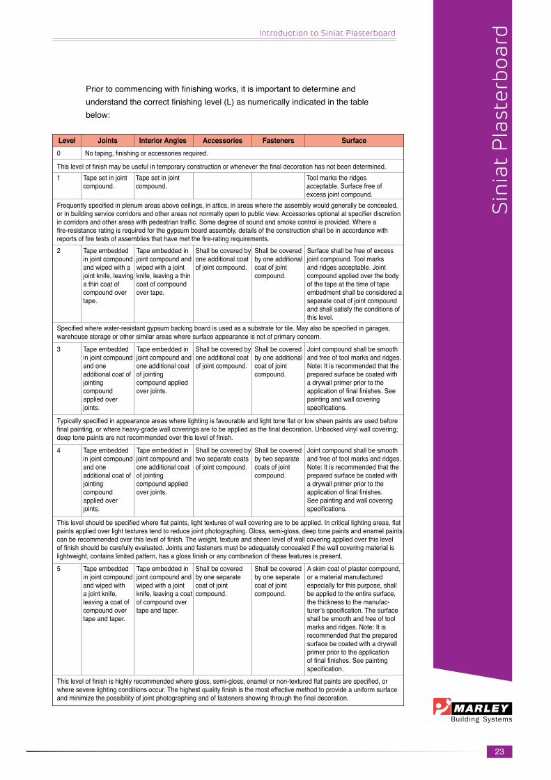
Priortocommencingwithfinishingworks,itisimportanttodetermineandunderstandthecorrectfinishinglevel(L)asnumericallyindicatedinthetablebelow:
Level Joints Interior Angles Accessories Fasteners Surface
Thisleveloffinishmaybeusefulintemporaryconstructionorwheneverthefinaldecorationhasnotbeendetermined.
0Notaping,finishingoraccessoriesrequired.
1 Tapesetinjointcompound.
Tapesetinjointcompound.
Toolmarkstheridgesacceptable.Surfacefreeofexcessjointcompound.
Frequentlyspecifiedinplenumareasaboveceilings,inattics,inareaswheretheassemblywouldgenerallybeconcealed,orinbuildingservicecorridorsandotherareasnotnormallyopentopublicview.Accessoriesoptionalatspecifierdiscretionincorridorsandotherareaswithpedestriantraffic.Somedegreeofsoundandsmokecontrolisprovided.Whereafire-resistanceratingisrequiredforthegypsumboardassembly,detailsoftheconstructionshallbeinaccordancewithreportsoffiretestsofassembliesthathavemetthefire-ratingrequirements.2 Tapeembedded
injointcompoundand wiped with a jointknife,leavingathincoatofcompoundovertape.
Tapeembeddedinjointcompoundandwipedwithajointknife,leavingathincoatofcompoundover tape.
Surfaceshallbefreeofexcessjointcompound.Toolmarksand ridges acceptable. Joint compoundappliedoverthebodyofthetapeatthetimeoftapeembedmentshallbeconsideredaseparatecoatofjointcompoundandshallsatisfytheconditionsofthis level.
Shallbecoveredbyone additional coat ofjointcompound.
Shall be covered byoneadditionalcoatofjointcompound.
Specifiedwherewater-resistantgypsumbackingboardisusedasasubstratefortile.Mayalsobespecifiedingarages,warehousestorageorothersimilarareaswheresurfaceappearanceisnotofprimaryconcern.
3 Tapeembeddedinjointcompoundand one additionalcoatofjointingcompoundapplied over joints.
Tapeembeddedinjointcompoundandone additional coat ofjointingcompoundappliedoverjoints.
Jointcompoundshallbesmoothandfreeoftoolmarksandridges.Note:Itisrecommendedthatthepreparedsurfacebecoatedwithadrywallprimerpriortotheapplicationoffinalfinishes.Seepainting and wall covering specifications.
Shallbecoveredbyone additional coat ofjointcompound.
Shall be covered byoneadditionalcoatofjointcompound.
Typicallyspecifiedinappearanceareaswherelightingisfavourableandlighttoneflatorlowsheenpaintsareusedbeforefinalpainting,orwhereheavy-gradewallcoveringsaretobeappliedasthefinaldecoration.Unbackedvinylwallcovering;deeptonepaintsarenotrecommendedoverthisleveloffinish.
4 Tapeembeddedinjointcompoundand one additionalcoatofjointingcompoundapplied over joints.
Tapeembeddedinjointcompoundandone additional coat ofjointingcompoundappliedoverjoints.
Jointcompoundshallbesmoothandfreeoftoolmarksandridges.Note:Itisrecommendedthatthepreparedsurfacebecoatedwithadrywallprimerpriortotheapplicationoffinalfinishes.See painting and wall covering specifications.
Shallbecoveredbytwo separate coats ofjointcompound.
Shall be covered bytwoseparatecoatsofjointcompound.
Thislevelshouldbespecifiedwhereflatpaints,lighttexturesofwallcoveringaretobeapplied.Incriticallightingareas,flatpaintsappliedoverlighttexturestendtoreducejointphotographing.Gloss,semi-gloss,deeptonepaintsandenamelpaintscanberecommendedoverthisleveloffinish.Theweight,textureandsheenlevelofwallcoveringappliedoverthisleveloffinishshouldbecarefullyevaluated.Jointsandfastenersmustbeadequatelyconcealedifthewallcoveringmaterialislightweight,containslimitedpattern,hasaglossfinishoranycombinationofthesefeaturesispresent.
5 Tapeembeddedinjointcompoundand wiped with ajointknife,leavingacoatofcompoundovertape and taper.
Tapeembeddedinjointcompoundandwipedwithajointknife,leavingacoatofcompoundovertape and taper.
Askimcoatofplastercompound,oramaterialmanufacturedespeciallyforthispurpose,shallbeappliedtotheentiresurface,thethicknesstothemanufac-turer’sspecification.Thesurfaceshallbesmoothandfreeoftoolmarksandridges.Note:Itisrecommendedthatthepreparedsurfacebecoatedwithadrywallprimerpriortotheapplicationoffinalfinishes.Seepaintingspecification.
Shall be covered byoneseparatecoatofjointcompound.
Shall be covered byoneseparatecoatofjointcompound.
Thisleveloffinishishighlyrecommendedwheregloss,semi-gloss,enamelornon-texturedflatpaintsarespecified,orwhereseverelightingconditionsoccur.Thehighestqualityfinishisthemosteffectivemethodtoprovideauniformsurfaceandminimizethepossibilityofjointphotographingandoffastenersshowingthroughthefinaldecoration.
Sin
iat
Pla
ster
boar
d

24
Internal partition system
SiniatPartitionSystemsarequicktoerectwithveryhighlevelsoffireandacousticperformance.Avarietyofdifferentspecificationoptionsachieveacousticinsulationstandardsupto65dBandfireresistanceupto150minutes.Thepartitionsusemetalstudswith12mmor15mmSiniatPlasterboard.SiniatFireCheckPlasterboardsareusedwhere60minutesormorefireresistanceisrequired. Componentsarelightandeasytohandle,quickandsimpletoinstall,andenableminimumwastage.MarleyBuildingSystemspartitionsaredimensionallyaccurateand will not bow, warp or shrink. Standard cut-outs in both studs and tracks accommodatemechanicalandelectricalserviceswithouttheneedforsite-formedholes.
Siniat Fixed Partition Systems
Sin
iat
Fixe
d P
arti
tion
Sys
tem
s
Plasterboard Jointing
Internal Partitioning System
Typical Plaster Joint Detail - Tape & Joint
Typical Locating of Studs
Internal Partitioning System
1. Drywallstudstobeinserted intofloorandceilingtrack withatwistmotion2. Allowa10mm clearancebetweentopof stud and track3. Erectstudsat400/600mmcts
Typical Plaster Joint for Flush Plastering
Siniat steel track
Siniat steel track
twist
twist stud into position
maintees@1200mmc/csupportedatevery1200mm,crosstees@400mmc/c
SiniatPlasterfinishtospecification(2-3mmthick)
50mmwidefibatapeTaper Edge Siniat Plasterboard
12/9mmSiniatPlasterboardfixedceilingtoSiniatplasterceilingteeswith25mmdrywallscrews@150mmc/cmaximum
25mmDrywallScrews
25mmDrywallScrews12/9mmSiniatPlasterboardfixedceiling to Siniat plaster ceiling tees with25mmdrywallscrews@150mmc/cmaximum
SiniatjointingPlastertospecification(minimum2coats)
50mmwidefibatape
Taper Edge Siniat Plasterboard
maintees@1200mmc/csupportedatevery1200mm,crosstees@400mmc/c
Taper Edge Siniat Plasterboard
SiniatjointingPlastertospecification(minimum2coats)50mmwidefibatape
12/12.5/15mmSiniatPlasterboardwith25mmdrywallscrews@220mmc/cmaximum
Siniat Stud25mmDrywallScrews

25
Typical Partition Layout
Internal Partitioning System
1. Setoutasrequired,allowing openingsonbottomtrackfor doorframes2. FixSiniattracktofloor3. Fix Siniat track to ceiling4. orFixheadsectionasrequired5. Positionstudsat400/600mmc/c
Siniat Fixed Partition Systems
Sin
iat
Fixe
d P
arti
tion
Sys
tem
s
Typical Stud Location at Door Openings
Internal Partitioning System
1. Door openings are constructed as per detail2. Extrasupportintheform timber/steeltubingwillbe requiredwhenhanging solid doors3. Check that the tracks are securelyfixed@400/600mm c/catends4. Check that the appropriate studs are secured5. Checkthatallstudsareproperlyspaced6. Checkallwallsarelevelandplumb7. Checkalldoorframesandopeningsareproperlyfixed
Typical Partition Corner Details
drywallscrew
Internal corner
Corner Bead 90DegreeCornerDetail
drywallstuds
Internal corner
drywallscrew
door opening
Door Detail
track
stud
track
intermediatestudsteelpoprivetfixing
trackflangedandfixedtostud
drywallandinternalpartitions
ROOMROOM

26
Typical Floor Track Location on Corners
Internal Partitioning System
1. Floortrackfixedasperdetail2. Toanchorthebottomtrack, usea6mmdiameterNylonnail inanchoraminimumof40mm intoaconcretesurfacebedslab. Theanchorsshouldbefixedthrough thesteelfoottrackadjacenttowhere thestudsarepositionedatnotmorethan600mmc/c
Siniat Fixed Partition Systems
Sin
iat
Fixe
d P
arti
tion
Sys
tem
s
Typical Door Frame Details
Internal Partitioning System
1. Steeldoorframesarefixed byscrewingdrywallstudsto fixingplateweldedinsidethe steeldoorframe2. Positionthestudtoallowfor plaster board location on other side
Typical “T” Junction Details
Internal Partitioning System
1. T-junctionstudserectedas per details allowing clearancebetweenAandB forplasterboard2. AlternateOption
cutoffsectionto locate track
drywallstud
steeldoorframe
wafertexscrewfixingplate
aluminium4legdoorframealuminiumsinklesshinge
door(40mm)bubble seal gasketSiniat stud
drywallscrewsSiniat plasterboard
aluminiumdoorframedetail
internal corner
drywallscrew
drywallstuds
centre line
1. T-Junction Detail
2. T-Junction Detail
internal corner
drywallscrew
drywallstuds
centre line

27
Siniat Fixed Partition Systems
Sin
iat
Fixe
d P
arti
tion
Sys
tem
s
Siniat Fixed Partition Systems
Standard Specifications for Drywall Systemsup to 3600mm
LPS51-0/1MarleyBuildingSystemDrywallInternalPartitionSystem
Non-loadbearingdrywallsystem12mmStandardPlasterboard-onelayereachside
APPLICATION:Commercial,educational
WALL PROPERTIES51mmstudSoundinsulationreductionindex 36dBThickness 76mmApproximateweight 20kg/m2
Material UsedA: 51mmDrywallsteelstudB: 52mmDrywallsteeltrackC: 12mmStandardTaperededgePlasterBoard 25mmDrywallScrews SiniatDrywalljointingsystem Floorandceilingfinishesasperspecification
APPLICATION DETAIL1. SetSiniatsteelstudsspacedat600mmc/cmaximum intosteeltrackatfloorandceiling2. Applyasinglelayerof12mmSiniatTaper edgeplasterboardtoeachsideusing25mm drywallscrewsspacedat220mmc/cmaximum3. Tapeandjointaccordingtospecification4. Refertostandardspecification5. Accousticperformancerequiressealingbetweentrack, floor,ceilingandanyotherabutmentjoints6. Staggertheplasterboardjointsinthesystem
LPF 58-0/1MarleyBuildingSystemDrywall
Non-loadbearingdrywallsystem15mmTechnicalFireCheckPlasterboard-onelayereachside
APPLICATION:Commercial,Residential&educational
WALL PROPERTIES58mmstudSoundinsulationreductionindex 40dBThickness 88mmApproximateweight 23kg/m2
Material UsedA: 58mmDrywallsteelstudB: 59mmDrywallsteeltrackC: 15mmStandardTaperededgePlasterBoard 25mmDrywallScrews SiniatDrywalljointingsystem Floorandceilingfinishesasperspecification
APPLICATION DETAIL1. SetSiniatsteelstudsspacedat600mmc/cmaximum intosteelatfloorandceiling2. Applyasinglelayerof15mmFireCheckTaperedge plasterboardtoeachsideusing25mmdrywallscrews spacedat220mmc/cmaximum3. Tapeandjointaccordingtospecification4. Refertostandardspecification5. Accousticperformancerequiressealingbetweentrack, floor,ceilingandanyotherabutmentjoints6. Staggertheplasterboardjointsinthesystem
600,0 0
A: 58mm Lafa rge steel stud
B: 5 9mm Lafarge steel t rack
C: 15mm Fire C heck board
600,00
A: Lafa rge 51mm steel s tud
B: Lafa rge steel t rack
C: 12mm Plaste rboard
A:58mmSiniatsteelstud
B:59mmSiniatSteelTrack
C:15mmFireCheckBoard
28
Siniat Fixed Partition Systems
Sin
iat
Fixe
d P
arti
tion
Sys
tem
s
600,00
A: Lafarge 64m m steel stud
B: Lafarge 65m m steel track
C: 15m m Standard Plasterboard
400,00
A: Lafarge 64m m steel stud
B: Lafarge 65m m steel track
C: 12m m Plasterboard
B:65mmSiniatSteelTrack
B:Siniat64mmsteelstud
C:15mmStandardPlasterboard
B:65mmSiniatSteelTrack
A:64mmSiniatSteelTrack
C:12mmPlasterboard
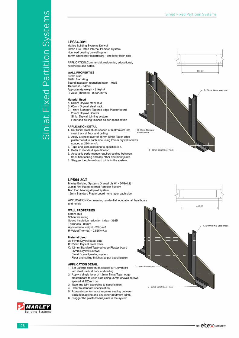
LPS64-30/2MarleyBuildingSystemsDrywallLfs64-30/2(4,2)30minFireRatedInternalPartitionSystemNonloadbearingdrywallsystem12mmStandardPlasterboard-onelayereachside
APPLICATION:Commercial,residential,educational,healthcareand hotels
WALL PROPERTIES64mmstud30MinfireratingSoundinsulationreductionindex-38dBThickness-88mmApproximateweight-21kg/m2R-Value(Thermal)-0.53K/m².w
Material UsedA:64mmDrywallsteelstudB:65mmDrywallsteeltrackC:12mmStandardTaperededgePlasterboard 25mmDrywallScrews SiniatDrywalljointingsystem Floorandceilingfinishesasperspecification
APPLICATION DETAIL1. SetLafargesteelstudsspacedat400mmc/c intosteeltrackatfloorandceiling.2. Applyasinglelayerof12mmSiniatTaperedge plasterboardtoeachsideusing25mmdrywallscrews spacedat220mmc/c3. Tapeandjointaccordingtospecification.4. Refertostandardspecification.5. Accousticperformancerequiressealingbetween track,floor,ceilingandanyotherabutmentjoints.6. Staggertheplasterboardjointsinthesystem.
LPS64-30/1MarleyBuildingSystemsDrywall30minFireRatedInternalPartitionSystemNonloadbearingdrywallsystem15mmStandardPlasterboard-onelayereachside
APPLICATION:Commercial,residential,educational,healthcare and hotels
WALL PROPERTIES64mmstud30MinfireratingSoundinsulationreductionindex-40dBThickness-94mmApproximateweight-21kg/m²R-Value(Thermal)-0.53K/m².W
Material UsedA:64mmDrywallsteelstudB:65mmDrywallsteeltrackC:15mmStandardTaperededgePlasterboard 25mmDrywallScrews SiniatDrywalljointingsystem Floorandceilingfinishesasperspecification
APPLICATION DETAIL1. SetSiniatsteelstudsspacedat600mmc/cinto steeltrackatfloorandceiling.2. Applyasinglelayerof15mmSiniatTaperedge plasterboardtoeachsideusing25mmdrywallscrews spacedat220mmc/c3. Tapeandjointaccordingtospecification.4. Refertostandardspecification.5. Accousticperformancerequiressealingbetween track,floor,ceilingandanyotherabutmentjoints.6. Staggertheplasterboardjointsinthesystem.

29
LPF64-60/2MarleyBuildingSystemsDrywall60minFireRatedInternalPartitionSystem
Non-loadbearingdrywallsystem12mmStandardPlasterboard-doublelayereachside
WALL PROPERTIES63.5mmstud60minFireRatingSound insulation reduction index 45dBThickness 112mmApproximateweight 39kg/m2
Material UsedA: 63.5mmDrywallsteelstudB: 65mmDrywallsteeltrackC: 12mmStandardTaperededgePlasterBoard 25mmand41mmDrywallScrews SiniatDrywalljointingsystem Floorandceilingfinishesasperspecification
APPLICATION DETAIL1. SetSiniatsteelstudsspacedat600mmc/cmaximum intosteeltrackatfloorandceiling2. Applyasinglelayerof12mmstandardplasterboard verticaltobothsidesusing25mmdrywallscrewsspaced at220mmc/cmaximumstaggerjoints3. Applyafacelayerof12mmstandardplasterboard tobothsidesstaggeringalljoints,using41mm drywallscrewsspacedat220mmc/cmaximum4. Tapeandjointaccordingtospecification5. Refertostandardspecification5. Accousticperformancerequiressealingbetweentrack, floor,ceilingandanyotherabutmentjoints6. Staggertheplasterboardjointsinthesystem7. SealalljointswithSiniatJointingPlaster
LPF64-60/1MarleyBuildingSystemsDrywallLpf64-60/160minFireRatedInternalPartitionSystem
Nonloadbearingdrywallsystem15mmTechnicalFireCheckPlasterboard-onelayereachside
APPLICATION:Commercial,residential,educational,healthcare and hotels
WALL PROPERTIES64mmstud60MinfireratingSoundinsulationreductionindex-40dBThickness-94mmApproximateweight-23kg/m2R-Value(Thermal)-0.53K/m².W
Material UsedA:64mmDrywallsteelstudB:65mmDrywallsteeltrackC:15mmFireCheckPlasterboard 25mmDrywallScrews SiniatDrywalljointingsystem Floorandceilingfinishesasperspecification
APPLICATION DETAIL1. SetSiniatsteelstudsspacedat600mmc/cintosteel trackatfloorandceiling.2. Applyasinglelayerof15mmFireCheckTaper edge plasterboard to each side using 25mmdrywallscrewsspacedat220mmc/c3. Tapeandjointaccordingtospecification.4. Refertostandardspecification.5. Accousticperformancerequiressealingbetween track,floor,ceilingandanyotherabutmentjoints.6. Staggertheplasterboardjointsinthesystem.
Siniat Fixed Partition Systems
Sin
iat
Fixe
d P
arti
tion
Sys
tem
s

30
Siniat Fixed Partition Systems
Sin
iat
Fixe
d P
arti
tion
Sys
tem
s
LPF64-60/3MarleyBuildingSystemsDrywallLpf64-60/360minFireRating
INTERNALPARTITIONSYSTEMNonloadbearingdrywallsystem12,5mmTechnicalFireCheckPlasterboard-onelayereachside,60kg/m³ofU-thermomatt6
WALL PROPERTIES64mmstud60minfireratingSoundreductionindexwithU-thermomatt6of60kg/m³60kg/m³-49dBThickness-89mmApproximateweight-30kg/m²R-Value(Thermal)-1.78K/m².W
Material UsedA:64mmDrywallsteelstudB:65mmDrywallsteeltrackC:12,5mmFireCheckboard 25mmDrywallScrews SiniatDrywalljointingsystem Floorandceilingfinishesasperspecification U-thermomattof60kg/m³
APPLICATION DETAIL1. Set Siniat steel studs spaced at 600mmc/cintosteeltrackatfloorandceiling.2. Applyasinglelayerof12,5mmfirecheckboardverticalto onesideusing25mmdrywallscrewsspacedat220mmc/c3. PositionInsulmattinsulationbetweenstuds,foldthetop overandsecuretotoptrackbypositioningandfixingwith galvanised angle4. Applyasinglelayerof12,5mmFireCheckboardvertical totheothersideusing25mmdrywallscrewsspacedat 220mmc/c5. Tapeandjointaccordingtospecification.6. Refertostandardspecification.7. Accousticperformancerequiressealingbetween track,floor,ceilingandanyotherabutmentjoints.8. Staggertheplasterboardjointsinthesystem.9. SealalljointswithSiniatJointingPlaster
LPF102-60/1MarleyBuildingSystemsDrywall60minFireRatedInternalPartitionSystem
Non-loadbearingdrywallsystem15mmTechnicalFireCheckPlasterboard-onelayereach side
APPLICATION: Residential
WALL PROPERTIES102mmstud60minFireRatingSoundinsulationreductionindex 40dBThickness 132mmApproximateweight 24kg/m2
Material UsedA: 102mmDrywallsteelstudB: 103mmDrywallsteeltrackC: 15mmFireCheckTaperededgePlasterBoard 25mmDrywallScrews SiniatDrywalljointingsystem Floorandceilingfinishesasperspecification
APPLICATION DETAIL1. SetSiniatsteelstudsspacedat600mmc/cmaximum intosteeltrackatfloorandceiling2. Applyasinglelayerof15mmFireCheckTaper edgeplasterboardtoeachsideusing25mm drywallscrewsspacedat220mmc/cmaximum staggerjoints3. Tapeandjointaccordingtospecification4. Refertostandardspecification5. Accousticperformancerequiressealingbetweentrack, floor,ceilingandanyotherabutmentjoints6. Staggertheplasterboardjointsinthesystem7. SealalljointswithSiniatJointingPlaster

31
Siniat Fixed Partition Systems
Sin
iat
Fixe
d P
arti
tion
Sys
tem
s
LPF64-120/1MarleyBuildingSystemsDrywallLpf64-120/1120minFireRatedInternalPartitionSystem
Nonloadbearingdrywallsystem12,5mmTechnicalFireCheckPlasterboard-0,5mmgalvanisedsteelbetweendoublelayerofTechnicalFireCheckPlasterboardon each side.
WALL PROPERTIES64mmstud120minfireratingSoundreductionindex-48dBThickness-115mmApproximateweight-50kg/m2ThermalR-Value-0.70kg/m2.W
Material UsedA:64mmDrywallsteelstudB:65mmDrywallsteeltrackC:12,5mmTaperEdgeTechnicalFireCheckboardD:0,5mmgalvanisedsteelsheet 25mmand41mmDrywallScrews SiniatDrywalljointingsystem Floorandceilingfinishesasperspecification
APPLICATION DETAIL1. SetSiniatsteelstudsspacedat600mmc/cintosteelat floorandceiling.2. Applyasinglelayerof12,5mmtaperedgefirecheck plasterboardverticaltoonesideusing25mmdrywall screwsspacedat220mmc/c3. Apply0,5mmgalvanisedsteelsheettoeachside(min30mmoverlap)4. Applyafacelayerof12,5mmtaperedgefirecheckplasterboardtobothsides.5. Tapeandjointaccordingtospecification.6. Refertostandardspecification.7. Accousticperformancerequiressealingbetweentrack,floor,ceilingandanyotherabutmentjoints.8. Staggertheplasterboardjointsinthesystem.9. Alljointstobeplastered.
Thissystemisalsosuitableforapplicationswheresevereimpactresistanceisrequired.
LPF64-60/2MarleyBuildingSystemsDrywallLpf64-60/260minFireRatedInternalPartitionSystem
Nonloadbearingdrywallsystem12mmStandardPlasterboard-doublelayereachside
WALL PROPERTIES64mmstud60minfireratingSound reduction index - 45dBThickness-112mmApproximateweight-39kg/m2R-Value(Thermal)-0.76kg/m2.W
Material UsedA:64mmDrywallsteelstudB:65mmDrywallsteeltrackC:12mmtaperededgeplasterboard 25mmand41mmDrywallScrews SiniatDrywalljointingsystem Floorandceilingfinishesasperspecification
APPLICATION DETAIL1. SetSiniatsteelstudsspacedat600mmc/c intosteeltrackatfloorandceiling.2.Applyasinglelayerof12mmstandardplasterboard verticaltobothsidesusing25mmdrywallscrews spacedat220mmc/c,staggerjoints.3. Applyafacelayerof12mmstandardplasterboardtoboth sidesstaggeringalljoints,using41mmdrywallscrews spacedat220mmc/c4. Tapeandjointaccordingtospecification.5. Refertostandardspecification.6. Accousticperformancerequiressealingbetweentrack,floor,ceilingandanyotherabutmentjoints.7. Staggertheplasterboardjointsinthesystem.8. SealalljointswithSiniatJointingPlaster

32
Siniat Fixed Partition Systems
Sin
iat
Fixe
d P
arti
tion
Sys
tem
s
LFG
par
titio
n sy
stem
Key
Fea
ture
s/dr
awin
g?So
und
Red
uctio
n(dB(Rw))
Fire
R
esis
tanc
e(min)
Part
ition
Wid
th(mm)
App
roxi
mat
eW
eigh
t(Kg/m
2 )
Hei
ght
(m)
Segm
ent/s
LPS
51 -
0/1
Nonloadbearingdryw
allsystem,12m
mStandard
Plasterboard-onelayereachside.S
teelstudsspacedat
600m
mc/cmaximum
.Drywallscrew
sspacedat220mm
c/cmaximum
.
LPS
51 -
0/1
Nonloadbearingdryw
allsystem,12m
mStandard
Plasterboard-onelayereachside.steelstudsspaced
at600mmc/c.drywallscrew
sspacedat220mmc/cwith
14-18kg/m³cavitybatt
LPS
58 -
0/1
Nonloadbearingdryw
allsystem,15m
mTechnicalFire
CheckPlasterboard-onelayereachside.S
teelstuds
spacedat600mmc/cmaximum
.Drywallscrew
sspaced
at220mmc/cmaximum
.
LPS
58 -
0/1
Nonloadbearingdryw
allsystem,15m
mStandard
Plasterboard-onelayereachside.
Steelstudsspacedat600mmc/c.drywallscrew
sspaced
at220mmc/cw
ith14-18kg/m³cavitybatt
LPS
64 -
30/1
(4,2
)Nonloadbearingdryw
allsystem,15m
mStandard
Plasterboard-onelayereachside.S
teelstudsspacedat
600m
mc/c.drywallscrew
sspacedat220mmc/c
36dB
40dB
40dB
45 d
B
40dB
0 0 0 0 30
76 76 88 88 94
20 20 23 23 21
3.6
3.6
3.6
3.6
3.6
Com
mercial
Com
mercial
Com
mercial
Res
iden
tial
Com
mercial
Com
mercial
Res
iden
tial
LPS
64 -
30/1
Nonloadbearingdryw
allsystem,15m
mStandard
Plasterboard-onelayereachside.S
teelstudsspacedat
600m
mc/c.drywallscrew
sspacedat220mmc/cw
ith
14-18kg/m³cavitybatt
LPF
64 -
30/2
(4.2
)Nonloadbearingdryw
allsystem,12m
mStandard
Plasterboard-onelayereachside.S
teelstudsspacedat
400m
mc/c.drywallscrew
sspacedat220mmc/c
46dB
3094
213.6
Com
mercial
Res
iden
tial
38dB
3088
214.
2Com
mercial
Res
iden
tial
Ther
mal
Valu
es(Rw)ink/m
2 .W0.47
0.47
0.50
0.50
0.53
0.53
0.53

33
Siniat Fixed Partition Systems
Sin
iat
Fixe
d P
arti
tion
Sys
tem
s
LFG
par
titio
n sy
stem
Key
Fea
ture
s/dr
awin
g?So
und
Red
uctio
n(dB(Rw))
Fire
R
esis
tanc
e(min)
Part
ition
Wid
th(mm)
App
roxi
mat
eW
eigh
t(Kg/m
2 )
Hei
ght
(m)
Segm
ent/s
LFS
64-3
0/2
(4.2
)Nonloadbearingdryw
allsystem,12m
mStandard
Plasterboard-onelayereachside.S
teelstudsspacedat
400m
mc/c.drywallscrew
sspacedat220mmc/cw
ith
14-18kg/m³cavitybatt
LFS
64-3
0/3
Nonloadbearingdryw
allsystem,12m
mStandard
Plasterboard-onelayereachside.S
teelstudsspaced
at600mmc/c.drywallscrew
sspacedat220mmc/c
LFS
64-3
0/3
Nonloadbearingdryw
allsystem,12m
mStandard
Plasterboard-onelayereachside.S
teelstudsspaced
at600mmc/c.drywallscrew
sspacedat220mmc/cwith
14-18kg/m³cavitybatt
LPF
64-6
0/1
Nonloadbearingdryw
allsystem,15m
mTechnicalFire
CheckPlasterboard-onelayereachside.S
teelstuds
spacedat600mmc/c.drywallscrew
sspacedat
220m
mc/c
LPF
64-6
0/1
Nonloadbearingdryw
allsystem,15m
mTechnicalFire
CheckPlasterboard-onelayereachside.S
teelstuds
spacedat600mmc/c.drywallscrew
sspacedat
220m
mc/cw
ith14-18kg/m³cavitybatt
41 d
B
38dB
41 d
B
40dB
48dB
30 30 30 60 60
88 88 88 94 94
21 21 21 23 23
4.2
3.6
3.6
3.6
3.6
Com
mercial
Res
iden
tial
Com
mercial
Res
iden
tial
Com
mercial
Res
iden
tial
Com
mercial
Com
mercial
Res
iden
tial
LFS
64-6
0/2
Nonloadbearingdryw
allsystem,12m
mStandard
Plasterboard-doublelayereachside.S
taggeredjoints.
steelstudsspacedat600mmc/c.drywallscrew
sspaced
at220mmc/c
LFS
64-6
0/2
Nonloadbearingdryw
allsystem,12m
mStandard
Plasterboard-doublelayereachside.S
taggeredjoints.
steelstudsspacedat600mmc/c.D
rywallscrew
sspaced
at220mmc/cw
ith14-18kg/m³cavitybatt
45 d
B60
112
393.6
Com
mercial
Res
iden
tial
52 d
B60
112
393.6
Com
mercial
Res
iden
tial
Ther
mal
Valu
es(Rw)ink/m
2 .W0.53
0.53
0.53
0.53
0.53
0.76
0.76

34
Siniat Fixed Partition Systems
Sin
iat
Fixe
d P
arti
tion
Sys
tem
s
LFG
par
titio
n sy
stem
Key
Fea
ture
s/dr
awin
g?So
und
Red
uctio
n(dB(Rw))
Fire
R
esis
tanc
e(min)
Part
ition
Wid
th(mm)
App
roxi
mat
eW
eigh
t(Kg/m
2 )
Hei
ght
(m)
Segm
ent/s
LPF
64-6
0/3
Nonloadbearingdryw
allsystem,12,5m
mTechnicalFire
CheckPlasterboard-onelayereachside.S
teelstuds
spacedat600mmc/c.drywallscrew
sspacedat220mm
c/cwith60kg/m³U
thermom
att6
LPF
64-1
20/1
Nonloadbearingdryw
allsystem,12,5m
mTe
chnical
FireCheckPlasterboard-doublelayereachsid
e,0,5m
m
galva
nize
d st
eel s
heet
bet
ween
pla
ster
boar
d.st
eel s
tuds
spacedat600mmc/c.drywa
llscrew
sspacedat220mmc/c
LPF
64-1
20/1
Nonloadbearingdryw
allsystem,12,5m
mTechnicalFire
CheckPlasterboard-onelayereachside.S
teelstuds
spacedat600mmc/c.drywallscrew
sspacedat220mm
c/cwith14-18kg/m³cavitybatt
LPF
64-1
20/2
(4.2
)No
nloadbearingdryw
allsystem,12,5m
mTechnica
lFireCheckPlasterboard-doublelayereachsid
e,0,5m
m
galva
nize
d st
eel s
heet
bet
ween
pla
ster
boar
d.st
eel s
tuds
spacedat400mmc/c.drywa
llscrew
sspacedat220mmc/c
LPF
64-1
20/2
(4.2
)No
nloa
dbearing
drywa
llsystem,12,5m
mTe
chnic
alFireCheck
Plasterboard-double
layereachsid
e,0,5m
mgalv
anize
dste
elsheetbetwe
enplas
terboard.steelstudssp
acedat400mmc/c.
dryw
allsc
rews
spacedat220mmc/cwith14-18kg/m³cavitybatt
44 d
B
48dB
53 d
B
40dB
53 d
B
60 120
120
120
120
88 115
115
115
115
20 50 50 50 50
3.6
3.6
3.6
4.2
3.6
Com
mercial
Res
iden
tial
Com
mercial
Com
mercial
Com
mercial
Com
mercial
LPF
64-1
20/3
Nonloadbearingdryw
allsystem,15m
mTechnicalFire
CheckPlasterboard-doublelayereachside.S
teelstuds
spacedat600mmc/c.drywallscrew
sspacedat
220m
mc/c
LPF
64/1
20/3
Nonloadbearingdryw
allsystem,15m
mTechnicalFire
CheckPlasterboard-doublelayereachside.S
teelstuds
spacedat600mmc/c.drywallscrew
sspacedat220mm
c/cwith14-18kg/m³cavitybatt
55 d
B120
124
543.6
Com
mercial
58dB
120
124
543.6
Com
mercial
Ther
mal
Valu
es(Rw)ink/m
2 .W1.78
0.70
0.70
0.70
0.70
0.76
0.76

35
Siniat Fixed Partition Systems
Sin
iat
Fixe
d P
arti
tion
Sys
tem
s
LFG
par
titio
n sy
stem
Key
Fea
ture
s/dr
awin
g?So
und
Red
uctio
n(dB(Rw))
Fire
R
esis
tanc
e(min)
Part
ition
Wid
th(mm)
App
roxi
mat
eW
eigh
t(Kg/m
2 )
Hei
ght
(m)
Segm
ent/s
LPF
102/
60/1
Nonloadbearingdryw
allsystem,15m
mTechnicalFire
CheckPlasterboard-onelayereachside.S
teelstuds
spacedat600mmc/c.D
rywallscrew
sspacedat
220m
mc/c
LPF
102-
60/1
Nonloadbearingdryw
allsystem,15m
mTechnica
lFire
CheckPlasterboard-onelayereachsid
e.steelstuds
spacedat600mmc/c.D
rywa
llscrew
sspacedat220mm
c/cwith14-18kg/m³cavitybatt
LPF
102-
120/
1Nonloadbearingdryw
allsystem
15mmTechnicalFireCheckPlasterboard-doublelayer
eachside.steelstudsspacedat600mmc/c.D
rywall
screwsspacedat220mmc/c
LPF
102-
120/
1No
nloadbearingdryw
allsystem
15mmTechnica
lFireCheckPlasterboard-doublelayer
eachside.steelstudsspacedat600mmc/c.D
rywa
llscrews
spacedat220mmc/cwith14-18kg/m³cavitybatt
40dB
51 d
B
50dB
60 60 120
120
132
132
162
162
24 24 46.5
46.5
3.6
3.6
3.6
3.6
Res
iden
tial
Res
iden
tial
Res
iden
tial
Res
iden
tial
Ther
mal
Valu
es(Rw)ink/m
2 .W0.72
0.72
0.72
0.72
36
Siniat Fixed Partition Systems
Sin
iat
Fixe
d P
arti
tion
Sys
tem
s
MA
XIM
UM
PA
RTI
TIO
N H
EIG
HTS
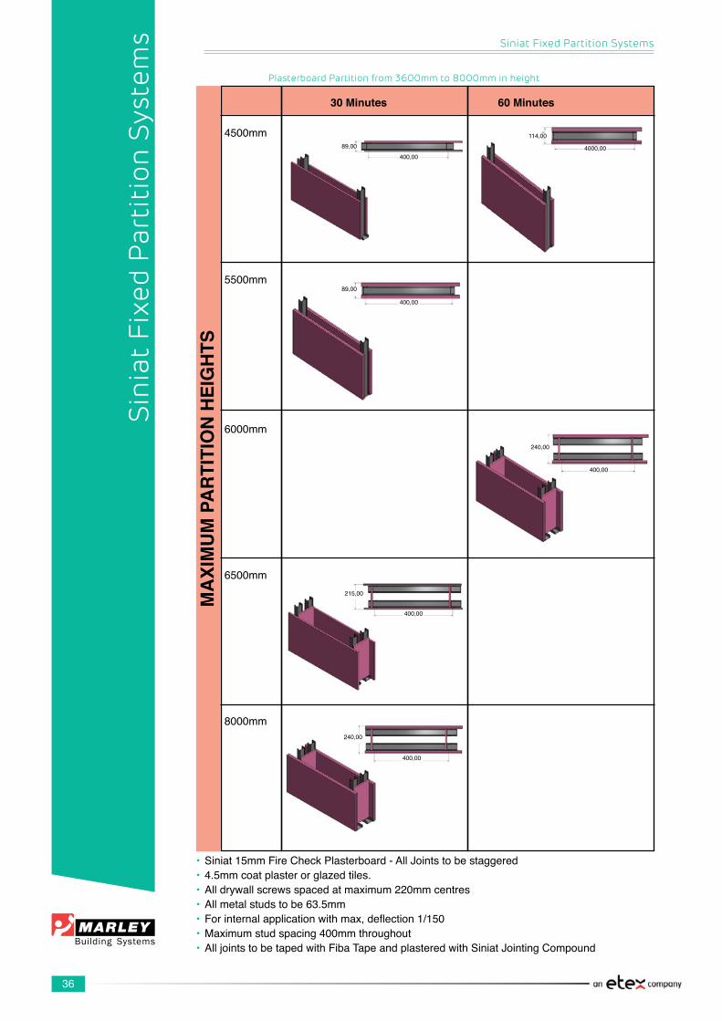
4500mm
5500mm
6000mm
6500mm
8000mm
30 Minutes 60 Minutes
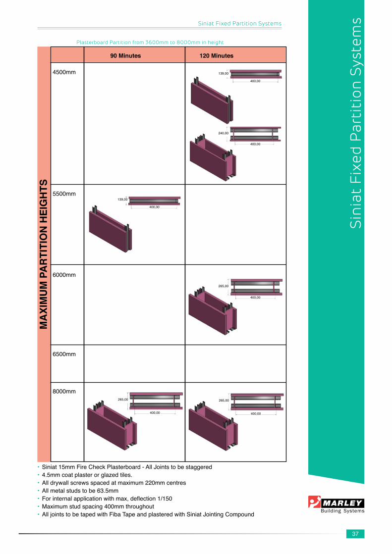
Plasterboard Partition from 3600mm to 8000mm in height
• Siniat15mmFireCheckPlasterboard-AllJointstobestaggered• 4.5mmcoatplasterorglazedtiles.• Alldrywallscrewsspacedatmaximum220mmcentres• Allmetalstudstobe63.5mm• Forinternalapplicationwithmax,deflection1/150• Maximumstudspacing400mmthroughout• AlljointstobetapedwithFibaTapeandplasteredwithSiniatJointingCompound
400,0089,00 4000,00
114,00
400,00
89,00
400,00
240,00
400,00
215,00
400,00
240,00
37
Siniat Fixed Partition Systems
Plasterboard Partition from 3600mm to 8000mm in height
Sin
iat
Fixe
d P
arti
tion
Sys
tem
s
• Siniat15mmFireCheckPlasterboard-AllJointstobestaggered• 4.5mmcoatplasterorglazedtiles.• Alldrywallscrewsspacedatmaximum220mmcentres• Allmetalstudstobe63.5mm• Forinternalapplicationwithmax,deflection1/150• Maximumstudspacing400mmthroughout• AlljointstobetapedwithFibaTapeandplasteredwithSiniatJointingCompound
MA
XIM
UM
PA
RTI
TIO
N H
EIG
HTS
4500mm
5500mm
6000mm
6500mm
8000mm
90 Minutes 120 Minutes
400,00
139,00
400,00
240,00
400,00
139,00
400,00
265,00
400,00
265,00
400,00
265,00
38
Siniat Fixed Partition Systems
Sin
iat
Fixe
d P
arti
tion
Sys
tem
s8100mm
9000mm
9500mm
10700mm
12500mm
30 Minutes 60 Minutes
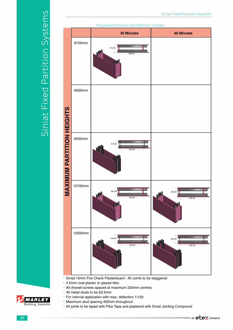
Plasterboard Partition over 8000mm in height
• Siniat15mmFireCheckPlasterboard-AllJointstobestaggered• 4.5mmcoatplasterorglazedtiles.• Alldrywallscrewsspacedatmaximum220mmcentres• Allmetalstudstobe63.5mm• Forinternalapplicationwithmax,deflection1/150• Maximumstudspacing400mmthroughout• AlljointstobetapedwithFibaTapeandplasteredwithSiniatJointingCompound
MA
XIM
UM
PA
RTI
TIO
N H
EIG
HTS
400,00
215,00
400,00
215,00
400,00
240,00
400,00
240,00
400,00
240,00
400,00
240,00
39
Siniat Fixed Partition Systems
8100mm
9000mm
9500mm
10700mm
12500mm
90 Minutes 120 Minutes
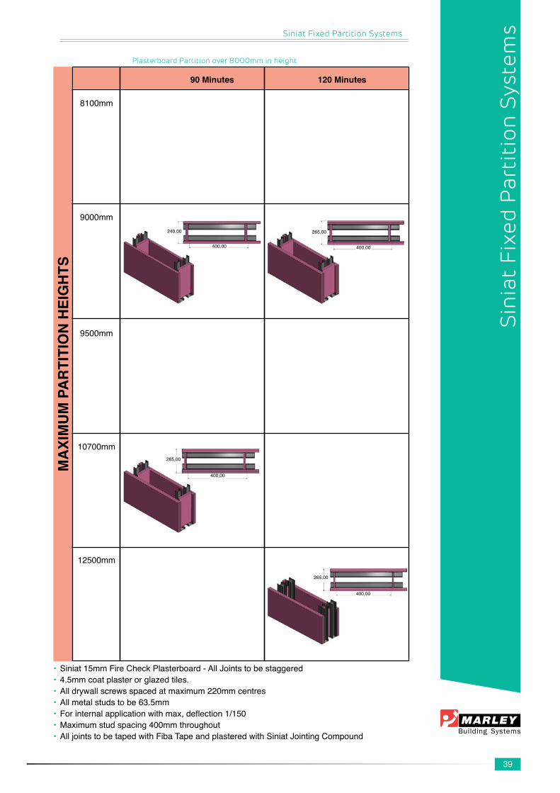
Plasterboard Partition over 8000mm in height
• Siniat15mmFireCheckPlasterboard-AllJointstobestaggered• 4.5mmcoatplasterorglazedtiles.• Alldrywallscrewsspacedatmaximum220mmcentres• Allmetalstudstobe63.5mm• Forinternalapplicationwithmax,deflection1/150• Maximumstudspacing400mmthroughout• AlljointstobetapedwithFibaTapeandplasteredwithSiniatJointingCompound
MA
XIM
UM
PA
RTI
TIO
N H
EIG
HTS
Sin
iat
Fixe
d P
arti
tion
Sys
tem
s
400,00
240,00
400,00
265,00
400,00
265,00
400,00
265,00
40
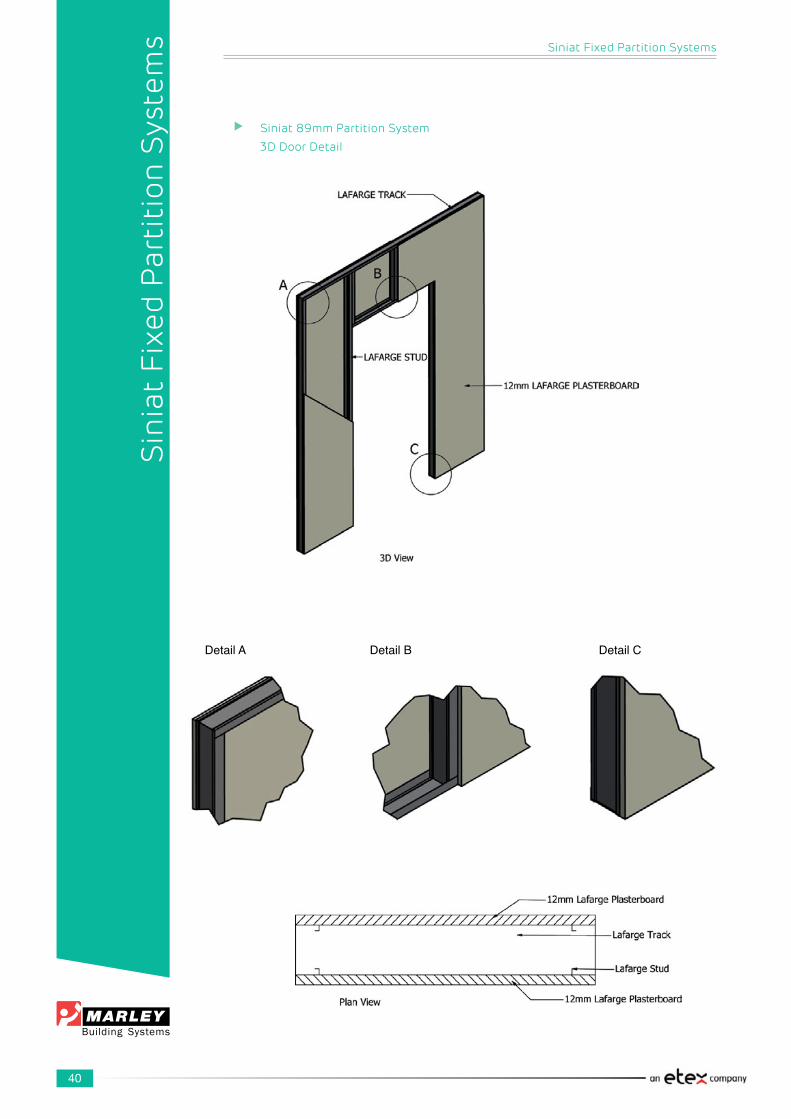
Siniat 89mm Partition System
3D Door Detail
Siniat Fixed Partition Systems
Sin
iat
Fixe
d P
arti
tion
Sys
tem
s
DetailA Detail B Detail C
41
Siniat Fixed Partition Systems
Sin
iat
Fixe
d P
arti
tion
Sys
tem
s
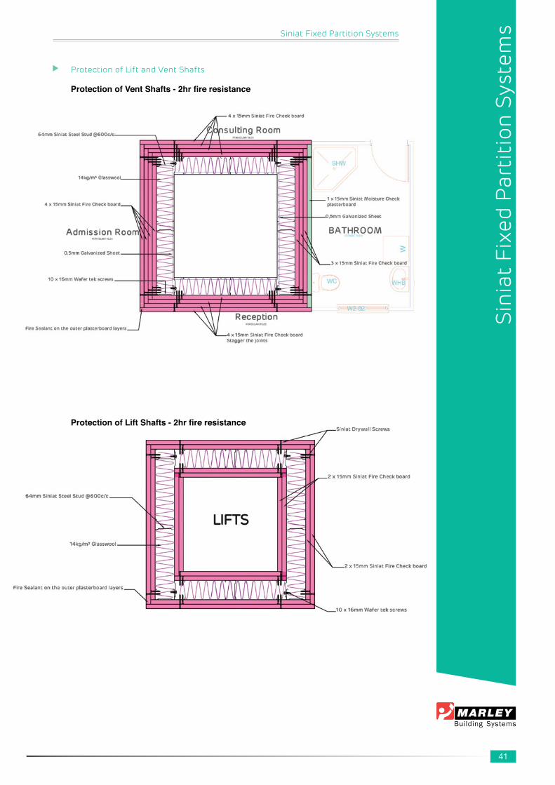
Protection of Lift and Vent Shafts
Protection of Vent Shafts - 2hr fire resistance
Protection of Lift Shafts - 2hr fire resistance

42
Siniat Fixed Partition Systems
Sin
iat
Fixe
d P
arti
tion
Sys
tem
s
Curved Walls
Siniat6.4mmStandardPlasterboardisrecommendedfortheconstructionofcurvedpartitionwalls.Theminimumradiusrecommendedis1000mm.Notchesinthebottomandtoptrackwilldependonthecurvaturerequired,butwillusuallyvarybetween120mmto300mm.Thewebwidthneedstobecompletelycut.
Thetracksarethenfoldedtoformthedesiredcurvature.Thebottomtrackneedtobesecuredtotheconcreteflooratintervalsnotexceeding300mm,usingNylonAnchorNails6mmx50mmorlarger.
Studspacingwillvarydependingonthecurvaturefrom120mmto400mm,butitshouldnotexceed400mm.Siniat6.4mmStandardPlasterboardsmustbeinstalledinahorizontaldirectionandsecuredtoeachstudwithSiniatdrywallscrewsnotmorethan220mmapart.ThesecondlayerofSiniat6.4mmStandardPlasterboardmustbestaggeredbyatleast600mmsothatthejointsofthefirstandsecondlayerofPlasterboardsarenotinlinewitheachother.
Alljointsinthesecondlayerofboards need to be taped with Fiba Tape andfinishedwithSiniat Jointing Plaster. ItisrecommendedthatthecompletesurfacebeskimmedwithSiniatSkim-Litetoobtainasmoothcurvature.

43
Siniat Door Frame Kit
1. IDWidth820mm±1.0mm2. Legstylesfinallengthtobecutonsitetosuitfloorlevel3. Dimensionstolerances0.50mm4. Materialthickness1.20mm5. Allsectionlengthshaveatoleranceof±1.0mm
Siniat Fixed Partition Systems
Sin
iat
Fixe
d P
arti
tion
Sys
tem
s
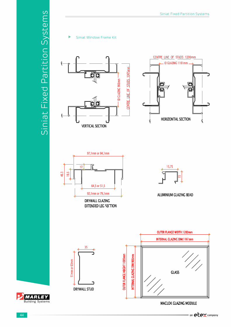
44
Siniat Window Frame Kit
Siniat Fixed Partition Systems
Sin
iat
Fixe
d P
arti
tion
Sys
tem
s
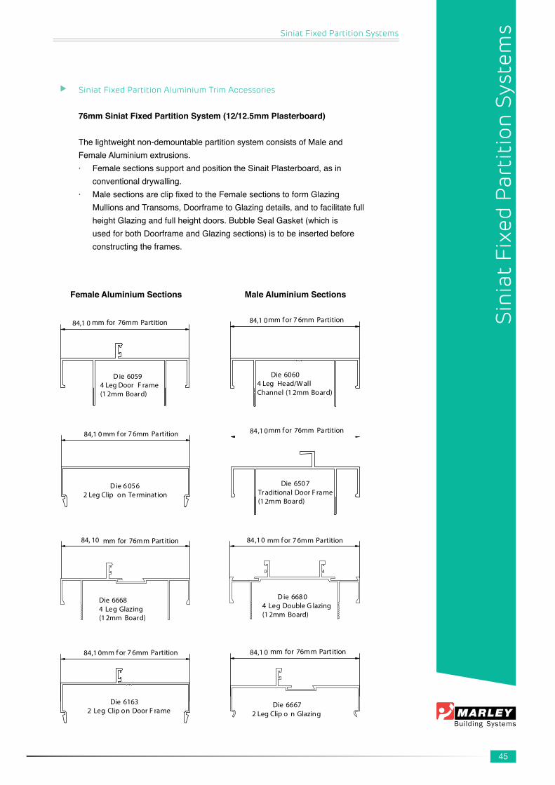
45
Siniat Fixed Partition Aluminium Trim Accessories
76mm Siniat Fixed Partition System (12/12.5mm Plasterboard)
Thelightweightnon-demountablepartitionsystemconsistsofMaleandFemaleAluminiumextrusions.· FemalesectionssupportandpositiontheSinaitPlasterboard,asin conventionaldrywalling.· MalesectionsareclipfixedtotheFemalesectionstoformGlazing MullionsandTransoms,DoorframetoGlazingdetails,andtofacilitatefull heightGlazingandfullheightdoors.BubbleSealGasket(whichis usedforbothDoorframeandGlazingsections)istobeinsertedbefore constructingtheframes.
Female Aluminium Sections Male Aluminium Sections
84,1 0 mm for 76mm Partition
D ie 60594 Leg Door F rame(1 2mm Board)
84,1 0mm f or 7 6mm Partition
Die 60604 Leg Head/W allChannel (1 2mm Board)
84,1 0 mm f or 7 6mm Partition
D ie 6 0562 Leg Clip on Termination
mm f or 76mm Partition
Die 650 7Tr aditional Door F rame(1 2mm Board)
84,1 0
84, 10 mm for 76mm Part ition
Die 66684 Leg Glazing (1 2mm Board)
84,10 mm f or 7 6mm Partition
D ie 668 04 Leg Double G lazing(1 2mm Board)
84,1 0mm f or 7 6mm Partition
Die 61632 Leg Clip on Door F rame
84,1 0 mm for 76mm Part ition
Die 66672 Leg Clip o n Glazing
Siniat Fixed Partition Systems
Sin
iat
Fixe
d P
arti
tion
Sys
tem
s
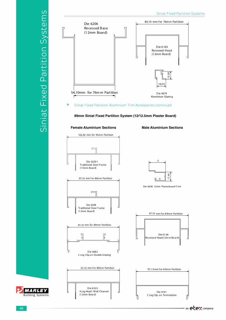
46
Siniat Fixed Partition Aluminium Trim Accessories continued
89mm Siniat Fixed Partition System (12/12.5mm Plaster Board)
Siniat Fixed Partition Systems
Sin
iat
Fixe
d P
arti
tion
Sys
tem
s
84,10 mm f or 76mm Part ition
D ie 6 165Recessed H ead(1 2mm Board)
14,0 0
15,0
0
D ie 6674 Aluminium Glazing
97,10 mm f or 89mm Partition
Die 6508Tr aditional Door F rame(1 2mm Board)
31 0
,5
17,4
0
Die 6638 12mm Plasterboard T rim
97,10 mm f or 8 9mm Partition
Die 61 66Re cesse d Head(12m m Bo ard)
97,10 mm f or 89mm Part ition
D ie 616 04 Leg Head /W all Channel(1 2mm Board)
97,1 0 mm f or 8 9mm Partition
Die 61612 Leg Clip on Termination
Die 6206Re cessed B ase(1 2mm Board)
54,10mm for 76m m Part ition
Female Aluminium Sections Male Aluminium Sections
97,10 mm for 89mm Partition
D ie 66822 Leg Clip on Double G lazing
102,30 mm for 95mm Part ition
Die 0230 1 Tr aditional Door F rame (1 5mm Board)

47
Female Aluminium Sections Male Aluminium Sections
Siniat Fixed Partition Systems
97,10
Die 66794 Leg Glazing(12mm Board)
mm for 89mm Partition 97,1 0 mm for 8 9mm Partition
D ie 667 64 Leg Do uble G lazing(1 2mm Board)
97,10 mm f or 8 9mm Partition
Die 616 42 Leg Clip o n Door F rame
97,10 mm f or 89mm drywall
Die 66782 Leg Clip on Glazing
14,00
15,0
0
D ie 6674 Aluminium Glazing
31,50
17,4
0
19,5 0
Die 630431,5 0
17,4
0
Die 6638 12mm Plasterboard T rim
Die 6207Recessed Base ( 12mm board)
67,10mm for 89 mm Part ition
Sin
iat
Fixe
d P
arti
tion
Sys
tem
s

48
Siniat Fixed Partition Aluminium Trim Accessories continued
89mm Siniat Fixed Partition System (15mm Plaster Board)
Female Aluminium Sections Male Aluminium Sections
Siniat Fixed Partition Systems
Sin
iat
Fixe
d P
arti
tion
Sys
tem
s
97,1 0mm for 8 9mm Part ition
Die 663 24 Leg Head /Wa ll Channel(15mm Board)
97,10 mm f or 89m m Part ition
Die 66774 Leg Glazin g( 15mm Board)
97,10 mm for 89mm Partition
Die 66334 Leg Do or F rame( 15mm B oard)
31,5 0
20,4
0
Die 6637 1 5mm Plaste rboard T rim
Siniat Fixed Partition Aluminium Trim Accessories continued
Aluminium Skirting: 75mm Ribbed Skirting
75,0 0
1,40
Die 1823
100, 00
1,80
Die 1830
Aluminium Skirting: 75mm Flat Skirting
Aluminium Skirting: 100mm Flat Skirting
2,50
Die 6144
75,00

49
Technical Specification:
• SiniatFixedPartition:76mm SupplyandinstallSiniatFixedPartitionfromSiniatdrywallpartitioning systemwithanalloverthicknessof76mmcomprisinginternal framingformedof51mmSiniatgalvanizedsteelstudsfixedat600mm centerstoSiniatgalvanizedsteeltrack/aluminiumfemaleheadsection andSiniatgalvanizedsteelfloortrack,wherenecessary,anyadditional galvanizedsteelstuddingtoformdooropenings,glazingandother apertures,anglesandcornersandterminatedends.Theinternalsteel framingistobedressedonbothsideswith12mmthickSiniat Plasterboardinsinglelengthstosuitheight,buttjointedandsecuredto steelstuddingwith25mmdrywallscrewsatmaximum220mmcenters. JointsaretobetapedandjointedwithSinaitJointingCompoundand preparedforpaintingorwallpapering.Allexternalaluminiumdoorframes, glazingframes,ceilingandwallchannelsandskirtingaretobeformedof naturalanodized/colouranodized/powdercoatedtospecificcolour.
Maximumheight:3600mm InstallationtobeinaccordancewithSABISA(SouthAfricanBuilding InteriorSystemsAssociation)installationguidelines
• SiniatFixedPartition:89mm SupplyandinstallSiniatFixedPartitionfromSiniantdrywallpartitioning systemwithanalloverthicknessof89mmcomprisinginternal framingformedof64mmSiniatgalvanizedsteelstudsfixedat600mm centerstoSiniatgalvanizedsteeltrack/aluminiumfemaleheadsection andSiniatgalvanizedsteelfloortrack,wherenecessary,anyadditional galvanizedsteelstuddingtoformdooropenings,glazingandother apertures,anglesandcornersandterminatedends.Theinternalsteel framingistobedressedonbothsideswith12mm/15mmthickSiniat Plasterboardinsinglelengthstosuitheight,buttjointedandsecuredto steelstuddingwith25mmdrywallscrewsatmaximum220mmcenters. JointsaretobetapedandjointedwithSiniatJointingCompoundand preparedforpaintingorwallpapering.Allexternalaluminiumdoorframes, glazingframes,ceilingandwallchannelsandskirtingaretobeformedof naturalanodized/colouranodized/powdercoatedtospecificcolour. Maximumheight:3600mm InstallationtobeinaccordancewithSABISA(SouthAfricanBuilding InteriorSystemsAssociation)installationguidelines
Siniat Fixed Partition Systems
Sin
iat
Fixe
d P
arti
tion
Sys
tem
s
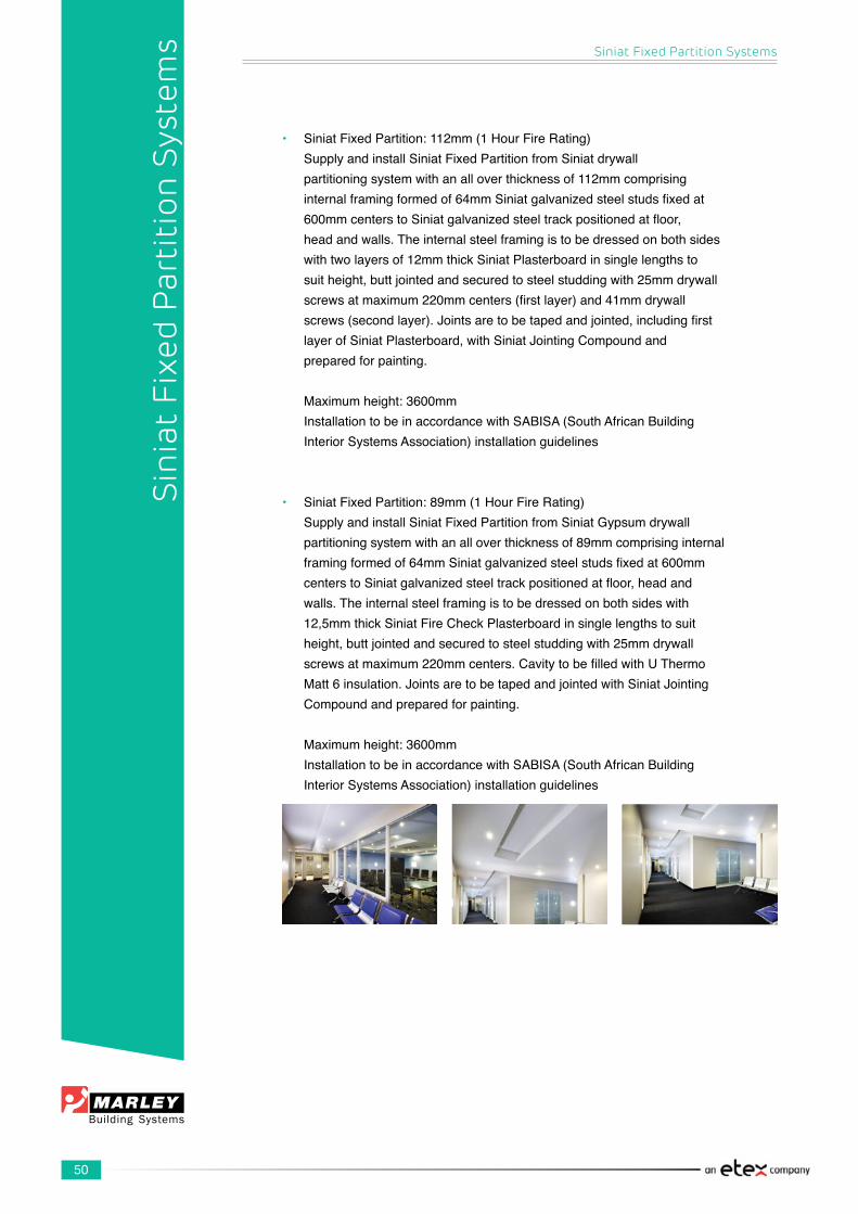
50
• SiniatFixedPartition:112mm(1HourFireRating) SupplyandinstallSiniatFixedPartitionfromSiniatdrywall partitioningsystemwithanalloverthicknessof112mmcomprising internalframingformedof64mmSiniatgalvanizedsteelstudsfixedat 600mmcenterstoSiniatgalvanizedsteeltrackpositionedatfloor, headandwalls.Theinternalsteelframingistobedressedonbothsides withtwolayersof12mmthickSiniatPlasterboardinsinglelengthsto suitheight,buttjointedandsecuredtosteelstuddingwith25mmdrywall screwsatmaximum220mmcenters(firstlayer)and41mmdrywall screws(secondlayer).Jointsaretobetapedandjointed,includingfirst layerofSiniatPlasterboard,withSiniatJointingCompoundand preparedforpainting.
Maximumheight:3600mm InstallationtobeinaccordancewithSABISA(SouthAfricanBuilding InteriorSystemsAssociation)installationguidelines
• SiniatFixedPartition:89mm(1HourFireRating) SupplyandinstallSiniatFixedPartitionfromSiniatGypsumdrywall partitioningsystemwithanalloverthicknessof89mmcomprisinginternal framingformedof64mmSiniatgalvanizedsteelstudsfixedat600mm centerstoSiniatgalvanizedsteeltrackpositionedatfloor,headand walls.Theinternalsteelframingistobedressedonbothsideswith 12,5mmthickSiniatFireCheckPlasterboardinsinglelengthstosuit height,buttjointedandsecuredtosteelstuddingwith25mmdrywall screwsatmaximum220mmcenters.CavitytobefilledwithUThermo Matt6insulation.JointsaretobetapedandjointedwithSiniatJointing Compoundandpreparedforpainting. Maximumheight:3600mm InstallationtobeinaccordancewithSABISA(SouthAfricanBuilding InteriorSystemsAssociation)installationguidelines
Siniat Fixed Partition Systems
Sin
iat
Fixe
d P
arti
tion
Sys
tem
s
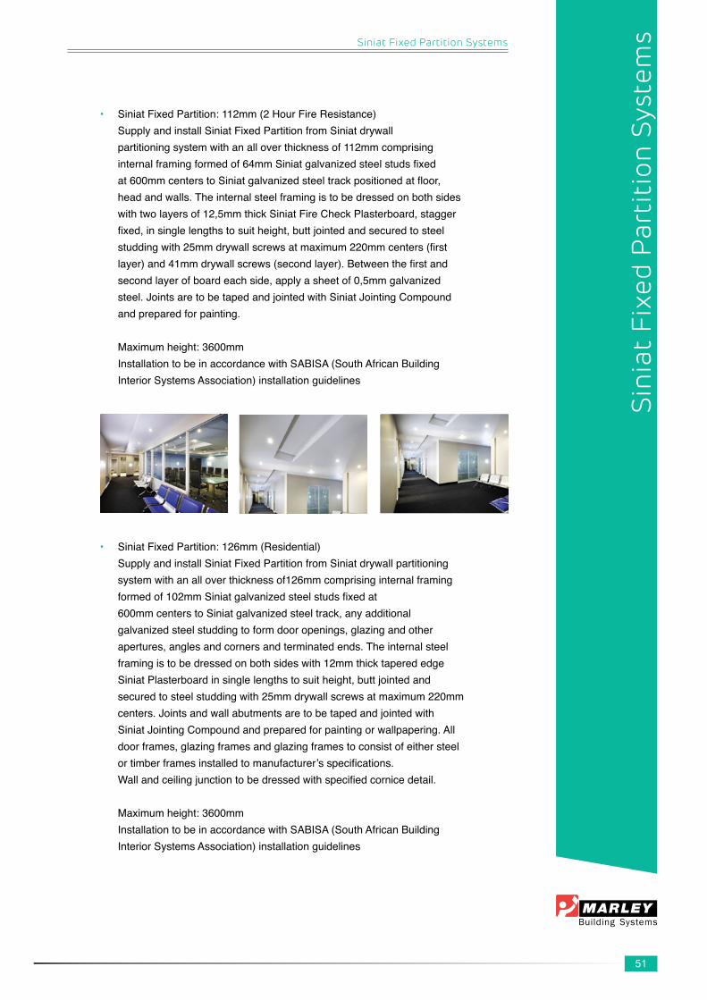
51
• SiniatFixedPartition:112mm(2HourFireResistance) SupplyandinstallSiniatFixedPartitionfromSiniatdrywall partitioningsystemwithanalloverthicknessof112mmcomprising internalframingformedof64mmSiniatgalvanizedsteelstudsfixed at600mmcenterstoSiniatgalvanizedsteeltrackpositionedatfloor, headandwalls.Theinternalsteelframingistobedressedonbothsides withtwolayersof12,5mmthickSiniatFireCheckPlasterboard,stagger fixed,insinglelengthstosuitheight,buttjointedandsecuredtosteel studdingwith25mmdrywallscrewsatmaximum220mmcenters(first layer)and41mmdrywallscrews(secondlayer).Betweenthefirstand secondlayerofboardeachside,applyasheetof0,5mmgalvanized steel.JointsaretobetapedandjointedwithSiniatJointingCompound andpreparedforpainting. Maximumheight:3600mm InstallationtobeinaccordancewithSABISA(SouthAfricanBuilding InteriorSystemsAssociation)installationguidelines
• SiniatFixedPartition:126mm(Residential) SupplyandinstallSiniatFixedPartitionfromSiniatdrywallpartitioning systemwithanalloverthicknessof126mmcomprisinginternalframing formedof102mmSiniatgalvanizedsteelstudsfixedat 600mmcenterstoSiniatgalvanizedsteeltrack,anyadditional galvanizedsteelstuddingtoformdooropenings,glazingandother apertures,anglesandcornersandterminatedends.Theinternalsteel framingistobedressedonbothsideswith12mmthicktaperededge SiniatPlasterboardinsinglelengthstosuitheight,buttjointedand securedtosteelstuddingwith25mmdrywallscrewsatmaximum220mm centers.Jointsandwallabutmentsaretobetapedandjointedwith SiniatJointingCompoundandpreparedforpaintingorwallpapering.All doorframes,glazingframesandglazingframestoconsistofeithersteel ortimberframesinstalledtomanufacturer’sspecifications. Wallandceilingjunctiontobedressedwithspecifiedcornicedetail.
Maximumheight:3600mm InstallationtobeinaccordancewithSABISA(SouthAfricanBuilding InteriorSystemsAssociation)installationguidelines
Siniat Fixed Partition Systems
Sin
iat
Fixe
d P
arti
tion
Sys
tem
s
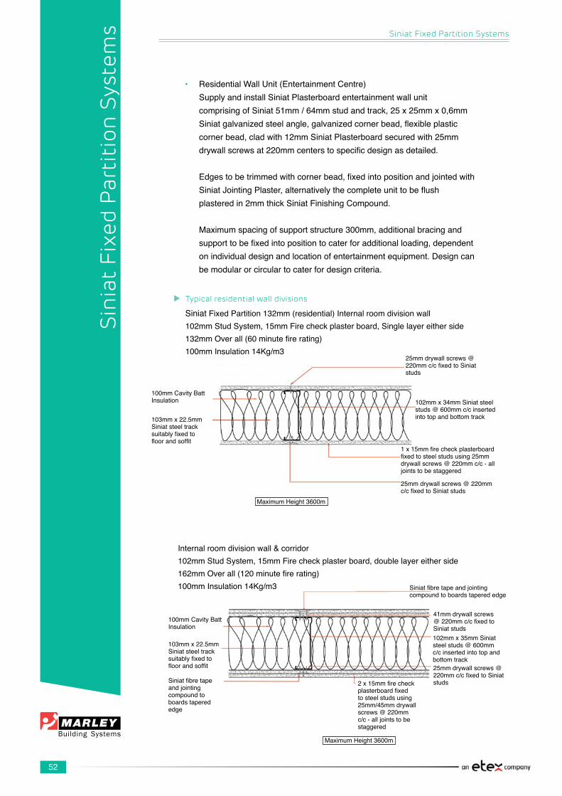
52
• ResidentialWallUnit(EntertainmentCentre) SupplyandinstallSiniatPlasterboardentertainmentwallunit comprisingofSiniat51mm/64mmstudandtrack,25x25mmx0,6mm Siniatgalvanizedsteelangle,galvanizedcornerbead,flexibleplastic cornerbead,cladwith12mmSiniatPlasterboardsecuredwith25mm drywallscrewsat220mmcenterstospecificdesignasdetailed.
Edgestobetrimmedwithcornerbead,fixedintopositionandjointedwith SiniatJointingPlaster,alternativelythecompleteunittobeflush plasteredin2mmthickSiniatFinishingCompound.
Maximumspacingofsupportstructure300mm,additionalbracingand supporttobefixedintopositiontocaterforadditionalloading,dependent onindividualdesignandlocationofentertainmentequipment.Designcan bemodularorcirculartocaterfordesigncriteria.
Siniat Fixed Partition Systems
Sin
iat
Fixe
d P
arti
tion
Sys
tem
s
SiniatFixedPartition132mm(residential)Internalroomdivisionwall102mmStudSystem,15mmFirecheckplasterboard,Singlelayereitherside132mmOverall(60minutefirerating)100mmInsulation14Kg/m3
25mmdrywallscrews@220mmc/cfixedtoSiniatstuds
102mmx34mmSiniatsteelstuds@600mmc/cinsertedintotopandbottomtrack
1x15mmfirecheckplasterboardfixedtosteelstudsusing25mmdrywallscrews@220mmc/c-alljointstobestaggered
25mmdrywallscrews@220mmc/cfixedtoSiniatstuds
100mmCavityBattInsulation
103mmx22.5mmSiniat steel track suitablyfixedtofloorandsoffit
MaximumHeight3600m
Internalroomdivisionwall&corridor102mmStudSystem,15mmFirecheckplasterboard,doublelayereitherside162mmOverall(120minutefirerating)100mmInsulation14Kg/m3
100mmCavityBattInsulation
103mmx22.5mmSiniat steel track suitablyfixedtofloorandsoffit
Siniatfibretapeandjointingcompoundtoboards tapered edge
MaximumHeight3600m
41mmdrywallscrews@220mmc/cfixedtoSiniat studs102mmx35mmSiniatsteelstuds@600mmc/cinsertedintotopandbottomtrack
Siniatfibretapeandjointingcompoundtoboardstaperededge
25mmdrywallscrews@220mmc/cfixedtoSiniatstuds2x15mmfirecheck
plasterboardfixedto steel studs using 25mm/45mmdrywallscrews@220mmc/c-alljointstobestaggered
Typical residential wall divisions

53
General:
IdentifyallcomponentsaswellasprefabricatedcomponentsPlan,calculateandmarkthelayoutofthepartitionPlantherequiredmaterialquantities
Siniat steel framing:Fixthetracktothefloor,cutasrequired,rememberingtoleavespacefordoor openings. Plumbupwardstocorrectlypositionandinstalltheceilingtrackorhead/wallchannel
AlternatelyfixheadchanneltotheceilingandplumbdownwardsInsertadditionalstudsforcornersandabutments.Loadbearingstudsandsuitabletimberinsertshouldbeusedtoachievethestrengthrequirementsoftheframingassemblyandadequatelysupporttheweightofthedoor.
Insulation:Fitsecurelywithclosedjoints,leavingnogaps.Unlesstheinsulationisself-supporting,fixtheinsulationatheadofframeusing25mmx25mmgalvanized angle.
Services:Allservicesaretobecompleted
Install Siniat Plasterboard:Establish a starting pointWheninstallingthefirstplasterboard,ensurethatthefirstjointwillbeplumb(asthewallmaynotbeplumb).Lineupthestudsasyouproceedfromhere,rememberthestudsarespacedat600mmcenters.Usesmallsectionsofplasterboardduringinstallationtokeepplasterboardsoffthegroundtopreventmoisturefromcreepinguptheplasterboards.Fixplasterboardstosteelframeworkusing25mmdrywallscrewsspacedat220mmcenters.Fixingsonplasterboardjointstobestaggered.
Vertical Joints:LightlybuttboardstogetherCenterjointsonstuds.Ensurethatthejointsonoppositesidesofstudsarestaggered.Fordoubl-layerboarding,staggerthejointsbetweenlayers.
Horizontal Joints:LightlybuttboardstogetherHorizontaljointswillnotbepermittedinwallslessthanorequalto3600mm,onlywallsover3600mm(exceedingthemaximumavailablelengthofboard).Agreepositionsofjointswherenotspecified,providehorizontalframingtosupportthehorizontaledgesofboards.Ensurethehorizontaljointsonoppositesidesofstudsarestaggered.Fordoubleboardlining,staggerjointsbetweenlayersbyatleast600mm.Providehorizontalframingtosupportthehorizontaledgesofthefirstlayeroftheplasterboard.
Siniat Fixed Partition Systems
Sin
iat
Fixe
d P
arti
tion
Sys
tem
s
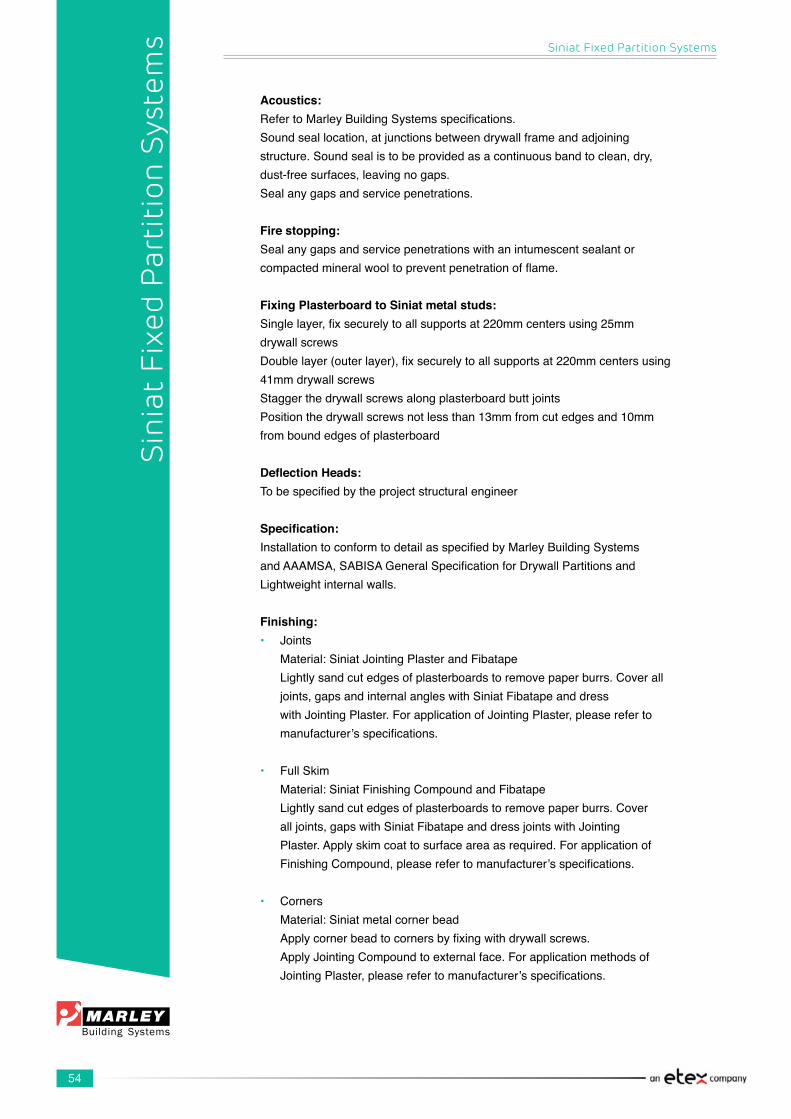
54
Acoustics:RefertoMarleyBuildingSystemsspecifications.Soundseallocation,atjunctionsbetweendrywallframeandadjoiningstructure.Soundsealistobeprovidedasacontinuousbandtoclean,dry,dust-freesurfaces,leavingnogaps.Sealanygapsandservicepenetrations.
Fire stopping:Sealanygapsandservicepenetrationswithanintumescentsealantorcompactedmineralwooltopreventpenetrationofflame.
Fixing Plasterboard to Siniat metal studs:Singlelayer,fixsecurelytoallsupportsat220mmcentersusing25mmdrywallscrewsDoublelayer(outerlayer),fixsecurelytoallsupportsat220mmcentersusing41mmdrywallscrewsStaggerthedrywallscrewsalongplasterboardbuttjointsPositionthedrywallscrewsnotlessthan13mmfromcutedgesand10mmfromboundedgesofplasterboard
Deflection Heads:Tobespecifiedbytheprojectstructuralengineer
Specification:InstallationtoconformtodetailasspecifiedbyMarleyBuildingSystemsandAAAMSA,SABISAGeneralSpecificationforDrywallPartitionsandLightweightinternalwalls.
Finishing:• Joints Material:SiniatJointingPlasterandFibatape Lightlysandcutedgesofplasterboardstoremovepaperburrs.Coverall joints,gapsandinternalangleswithSiniatFibatapeanddress withJointingPlaster.ForapplicationofJointingPlaster,pleasereferto manufacturer’sspecifications.
• FullSkim Material:SiniatFinishingCompoundandFibatape Lightlysandcutedgesofplasterboardstoremovepaperburrs.Cover alljoints,gapswithSiniatFibatapeanddressjointswithJointing Plaster.Applyskimcoattosurfaceareaasrequired.Forapplicationof FinishingCompound,pleaserefertomanufacturer’sspecifications.
• Corners Material:Siniatmetalcornerbead Applycornerbeadtocornersbyfixingwithdrywallscrews. ApplyJointingCompoundtoexternalface.Forapplicationmethodsof JointingPlaster,pleaserefertomanufacturer’sspecifications.
Siniat Fixed Partition Systems
Sin
iat
Fixe
d P
arti
tion
Sys
tem
s

55
• Painting Plaster Finishes: Sandjointssmoothusing80gritsandpaper Shouldlightsandpaperingberequiredonplasteredceilings,thiscan be done UseonlyPVAwater-basedpaint Consultpaintmanufacturerforrecommendations Drawingreference:
Wet Area Specification:
• Drywall:
Performance Criteria:Asperdrywallsystem
Framework: Studs:102mm,64mmx35mmSiniatStudsat400mmcenters FloorTrack:102mm,64mmx22,5mmSiniatTrackfixedwith tworowsofstaggeredfixingsat400mmcenters. HeadTrack:102mm,64mmxx22,5mmSiniatTrackfixedwithtworows ofstaggeredfixingsat400mmcenters Fixingdetailsasperspecification
Note:Additionaltimbersupportspositionedandfixedwithinstuds,as nogginsforsupportoffittings&fixture AdequatesupporttobeprovidedforHeadTrack
Deflectionallowance:Tobedeterminedbystructuralengineer
Lining: Asperdrywallspecification.Onelayerof12,5mmMoistureCheck Plasterboardasfacelayer. Plasterboardbackinglayerasrequired&specified Fixplasterboardwith25mmdrywallscrewsat220mmcenters Finishing:ApplyFibatapetoalljoints,skimjointswithSiniatJointing Plasterandifrequired,fullskimwithSiniatFinishingCompound.
Insulation: Cavityinsulation:1200mmx600mmx100mm/50mmCavityBatt
Siniat Fixed Partition Systems
Sin
iat
Fixe
d P
arti
tion
Sys
tem
s
56
Siniat Fixed Partition Systems
Sin
iat
Fixe
d P
arti
tion
Sys
tem
s
• Tiling to Plasterboard: MetalStudPartition–CeramicTiles
Performance Criteria: Maximumallowableload:20kg/m2
Framework: Studs:“102mm/64mmx35mmSiniatStuds”at400mmcenters FloorTrack:102mm/64mmx22,5mmSiniatTrack HeadTrack:102mm/64mmx22,5mmSiniatTrack(unlessdetermined otherwisebydeflection) HeadCondition:Fixedtoundersideofstructuralsoffit. DeflectionAllowance:Tobedeterminedbystructuralengineer.
Lining: 1Layer12,5mmSiniatMoistureCheckPlasterboardsealedusing sealer.Screwsfirstlininglayerwith25mmdrywallscrewsat220mm centers.CavityInsulation:1200mmx600mmx100mm/50mmCavity Batt Finishing:ApplyFibatapetoalljoints,skimjointswithSiniatJointing PlasterandifrequiredfullskimwithSiniatFinishingCompound. Finishing Requirements:Tiledsurface SiniatCornerBeadtoallexternalcornersfinishedwithSiniatJointing Compound FibtapetoallinternalcornersfinishedwithJointingCompounds. SurfacePreparation: Mix20kgTylon“PlaskeyCI250”with10litresofTylon“Key-itCT117”. Applythemixturetodrywallwithablockbrush–thickness2mm. Allowtodryfor24hoursbeforecommencingtiling.
Ceramic Tiles: Alwaysfixtilestoprimeddrywall.UseTylon“WallnFloorCM11”tile adhesive.Applysubstratetoaminimumbasethicknessof3mm.Allow theadhesivetodryfor24hoursbeforegrouting. Shouldlarge,heavyorfloortilesbeused,thenthefloortrowelmustbe usedtospreadtheadhesivetoa6mmbeddedthickness.
Grouting: GroutwithTylonTieGrout“CE33”cement-basedgrout. FormorewaterresistancethegroutmustbemixedwithTylonBond-It (replacethewaternormallyusedinthemix). Alongthewalledgesandcornersapplysiliconinsteadofgrout.

57
Siniat Fixed Partition Systems
• Tiling to Plasterboard: MetalStudPartition–PaintedSurface
Framework: Studs:“102mm,64mmx35mmSiniatStuds”at400mmcenters FloorTrack:102mm,64mmx22,5mmSiniatTrack HeadTrack:102mm,64mmx22,5mmSiniatTrack(unlessdetermined otherwisebydeflection) HeadCondition:Fixedtoundersideofstructuralsoffit DeflectionAllowance:Tobedeterminedbystructuralengineer
Lining: 1Layer12,5mmSiniatMoistureCheckPlasterboardsealedusing sealer Screwsfirstlininglayerwith25mmdrywallscrewsat220mmcenters CavityInsulation:1200mmx600mmx100mm,50mmCavityBatt
Finishing: ApplyFibatapetoalljoints,skimjointswithSiniatJointingPlasterandif required,fullskimwithSiniatFinishingCompound.
Finishing Requirements: Paintedsurface SealsurfaceofplasterboardwithTylonBond-it.Allow24hourstodry. PlasterthecompletesurfacewithSiniatFinishingCompound.Allow24 hourstodry. SealplasteredsurvacewithTylonBond-it.Allow24hourstodry. Paintsurfacewithmanufacturer’srecommendedpaintforwetareas.
Alongthewalledgesandcornersapplysiliconinsteadofgrout.
Inbothapplications,keeptheplasterboard10mmoffthefloorandbefore decorationsealthisgapwithsuitablesiliconeorPolysulphidesealant. Beforedecoration,sealallverticalandhorizontaljointswithsuitable siliconeorPolysulphidesealant.
Sin
iat
Fixe
d P
arti
tion
Sys
tem
s

58
Siniat Fixed Partition Systems
Sin
iat
Fixe
d P
arti
tion
Sys
tem
s
Construction Details for Wet Areas

59
Siniat Fixed Partition Systems
Fixtures and Fittings:
Thereisawidevarietyofcomponentssuitableforsecuringfixturesandfittingstodrywalling.Generally,thechoiceofindividualfixingcomponentswilldependonthetypeofsystemsandtheloadingrequirements.
Thissectiongivesrecommendationsontheselectionofgenericfixings.
Considerthelayoutoffixturesandfittingsatthedesignstagetoallownecessarysupports to be provided.
Theguidancegivenisprimarilyconcernedwithfixturesatthetimeofinstallation.
Subsequentinstallationislesseasy,especiallyforheavierfixtureswhichwilloftenrequireidentificationofthebasicframeinhollowpartitions.
Fixing(otherthantosecurelightweightcomponents)shouldbemadeintostuds,fixingchannel,ortimbernoggins.
Mediumtoheavyweightcomponentsarerequiredtobesupportedbetweenstuds.
Methods of fixing to Siniat Partition Systems:
1. Pictures, Calendars, etc: Useeithera‘stick-on’typeofpicturehangerorthenailandhooktype as per detail. Ensure that the nail is driven downwards into the Siniat Plasterboardatanangleofapproximately20°.
2. Mirrors,Ornaments,etc: UseabutterflybolttypeoffastenerwhichisfittedontotheSiniat Plasterboardinanyposition.
3. MediumObjects(shelves): Fixthroughtheplasterboardintothedrywallstudwithself-tapping screws,orintoacross-memberbetweenstudswhichshouldbeprovided duringerectionoftheframing,oruseabutterflybolt-typefastener.
4. Heavy-DutyObjects(handbasins,cisterns,etc): Drywallstudsshouldbespacedmoreclosely(e.g.300mm).Run horizontaltimbernogginsofupto114mmx38mmordouble-nestedtrack channels between the vertical notched studs and secure with screw. Fix objectstonogginsandstuds.
5. Extra-HeavyObjects: Itemssubjecttosevereabuseorimpactshouldbesupportedbyasteel frameworkwhichisboltedtothefloorandstuds.
Note:PleasenotethatallplumbingandelectricalfittingdesignsneedtobesignedoffbythearchitectandneedtocomplywiththerequirementsofSANS10400:XA-2011
Sin
iat
Fixe
d P
arti
tion
Sys
tem
s

60
Siniat Fixed Partition Systems
Sin
iat
Fixe
d P
arti
tion
Sys
tem
s
1. Siniat Plasterboard, Fire Check or Moisture Check boards
2. Siniat Stud – use 102mm load-bearing stud for hanging toilets, baths, basins and
urinals
3. Electrical trunking
4. Crush rail
5. SiniatNogginfixedtotheSiniatstudwithaSiniatWafertexscrew(Changeshape
toreflectanoggin)
6. Metalbacksocketbox
7. Galvanizedplate(Changeshapetoreflectastripofgalvanizedsheet)
8. Wallcupboard
9. 150mmx50mmGradeVtimber
10. Foldingsupportrail
11. Replacewithanglesectionsforthelengthoftheboard.Theanglesectionsaretobe
fixedtowebofthestudsandtheotherfacewillofferfixingfortheboard.
12. 18mmPlywood
2
3
1
2
5
6
1
2
9
1
10
2
4
1
2
7
8
1
2
11
1
12

61
Siniat Fixed Partition Systems
Plasterboard Fitting and Fixing Details
1. Siniat Plaster board2. Siniat Studs
A/B/C-FixingtoplasterboardD - Fixing to StudE-FixingtoNogging
SiniatDrywallStud
DrywallScrew,FixingtoVerticalStudHollowWallAnchorWithHook
HollowWallAnchorWithWasher
NylonPlasterboardAnchor
DepthofDrywallScrews
Correct Depth Too Deep Too Shallow
FixingtoNogginDetail
Sin
iat
Fixe
d P
arti
tion
Sys
tem
s
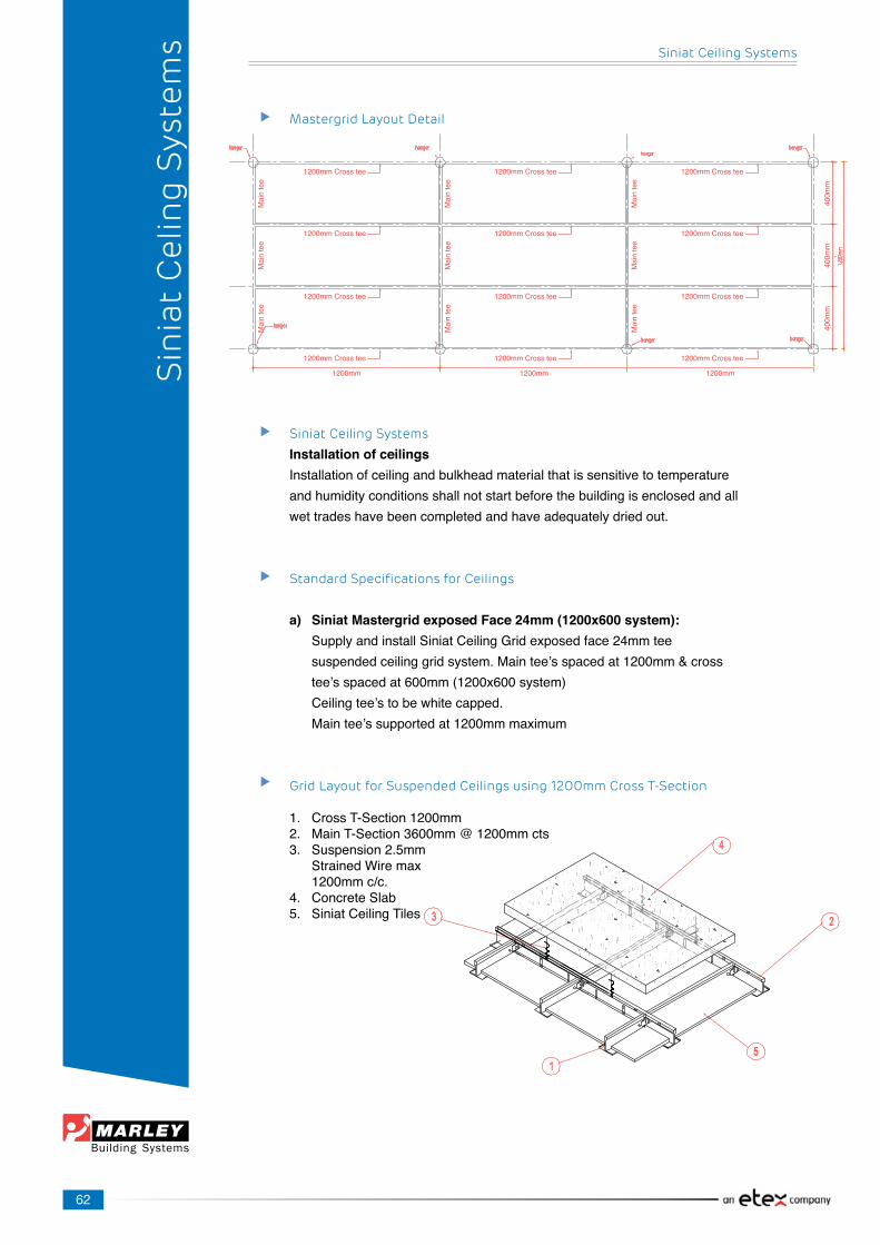
62
400m
m
Siniat Ceiling Systems
Sin
iat
Cel
ing
Sys
tem
s
Siniat Ceiling Systems
Installation of ceilingsInstallationofceilingandbulkheadmaterialthatissensitivetotemperatureandhumidityconditionsshallnotstartbeforethebuildingisenclosedandallwettradeshavebeencompletedandhaveadequatelydriedout.
Standard Specifications for Ceilings
a) Siniat Mastergrid exposed Face 24mm (1200x600 system): SupplyandinstallSiniatCeilingGridexposedface24mmtee suspendedceilinggridsystem.Maintee’sspacedat1200mm&cross tee’sspacedat600mm(1200x600system) Ceilingtee’stobewhitecapped. Maintee’ssupportedat1200mmmaximum
Grid Layout for Suspended Ceilings using 1200mm Cross T-Section
1. CrossT-Section1200mm2. MainT-Section3600mm@1200mmcts3. Suspension2.5mm StrainedWiremax 1200mmc/c.4. Concrete Slab5. Siniat Ceiling Tiles
Mastergrid Layout Detail
1200mmCrosstee1200mmCrosstee 1200mmCrosstee
1200mmCrosstee1200mmCrosstee 1200mmCrosstee
1200mmCrosstee1200mmCrosstee 1200mmCrosstee
1200mmCrosstee1200mmCrosstee 1200mmCrosstee
1200mm1200mm1200mm
Maintee
Maintee
Maintee
Maintee
Maintee
Maintee
Maintee
Maintee
Maintee
400m
m400m
m

63
PurlinPurlin Clip
Suspension2.5mmStrainedWire
1.6mmGalvAngleCleat Suspension2.5mmStrainedWire
Concrete Slab
EyePin
Concrete Slab
Suspension2.5mmStrainedWire
Siniat Ceiling Systems
Sin
iat
Cel
ing
Sys
tem
s
b) Siniat Ceiling Grid exposed Face 24mm (600x600 system): SupplyandinstallSiniatCeilingGridexposedface24mmtee suspendedceilinggridsystem.Maintee’sspacedat1200mm&cross tee’sspacedat600mmwith600mmcrosstee’sspacedbetween 1200mmcrosstee’sat600centers(600x600system) Ceilingtee’stobewhitecapped. Maintee’ssupportedat1200mmmaximum Grid Layout for Suspended Ceilings
using 600mm Cross T-Section
1. CrossT-Section600mm2. MainT-Section3600mm @1200mmcts3. Suspension2.5mmStrained Wiremax1200mmc/c4. Concrete Slab5. Siniat Ceiling Tiles
Sub-Grid Detail (Strained Wire)
Exposed Ceiling
Grid Layout for Lay-In Ceilings Subgrid detailfor plenums of more than 3m
1. Cross T-Section 1200mm@600c/c2. MainT-Section 3600@1200mmc/c3. Siniat Ceiling Tiles4. StrainedWireof2.5mm5. SubGridChannel1200c/c6. GalvAngleLateral supports@1200c/c
Typical suspension details
Suspension Details for Exposed Ceiling Grid
Onlysidefixingisrecommendedanditisnotrecommendedthatfixingsthatrelyonpullforceareused.Thefollowingminimumanchorsarerecommendedforsidefixing:
Typeofrooftrussorfloorjoists
Systemswithuptotwolayersofboard
Systemswiththreelayersofboard
Steel including light weight steel
One5mmx20mmTekscrew
Two5mmx20mmTekscrews
Timber
One6mmx30mmchipboardscrew
Two6mmx50mmchipboardscrews
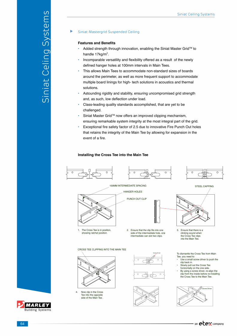
64
Siniat Ceiling Systems
Sin
iat
Cel
ing
Sys
tem
s
Siniat Mastergrid Suspended Ceiling
Features and Benefits• Addedstrengththroughinnovation,enablingtheSiniatMasterGridTM to handle17kg/m2.• Incomparableversatilityandflexibilityofferedasaresultofthenewly definedhangerholesat100mmintervalsinMainTees.• ThisallowsMainTeestoaccommodatenon-standardsizesofboards aroundtheperimeter,aswellasmorefrequentsupporttoaccommodate multipleboardliningsforhigh-techsolutionsinacousticsandthermal solutions.• Astoundingrigidityandstability,ensuringuncompromisedgridstrength and,assuch,lowdeflectionunderload.• Class-leadingqualitystandardsaccomplished,thatareyettobe challenged.• SiniatMasterGridTMnowoffersanimprovedclippingmechanism, ensuringremarkablesystemintegrityatthemostintegralpartofthegrid.• Exceptionalfiresafetyfactorof2.5duetoinnovativeFirePunchOutholes thatretainstheintegrityoftheMainTeebyallowingforexpansioninthe eventofafire.
Installing the Cross Tee into the Main Tee
Screw Driver
Screw Driver
The Cross Tee is in position,showing ratchet position.
Ensurethattheclipfitsintoonesideoftheintermediatehole,oneintermediatecanslottwoclips.
Ensure that there is a clicking sound when the Cross Tee clips intotheMainTee.
TodismantletheCrossTeefromMainTee,youneedto:• Useasmallscrewdrivertopushthe clip back in.• SlowlypullouttheCrossTee horizontallyontheoneside.• Byusingascrewdriver,re-alignthe clipfromtheinsidebeforere-installing theCrossTeetotheMainTee.
NowclipintheCrossTee into the oppositesideoftheMainTee.
1. 2. 3.
4.
100MMINTERMEDIATESPACING
HANGERHOLES
PUNCHOUTCLIP
CROSSTEECLIPPINGINTOTHEMAINTEE
STEELCAPPING
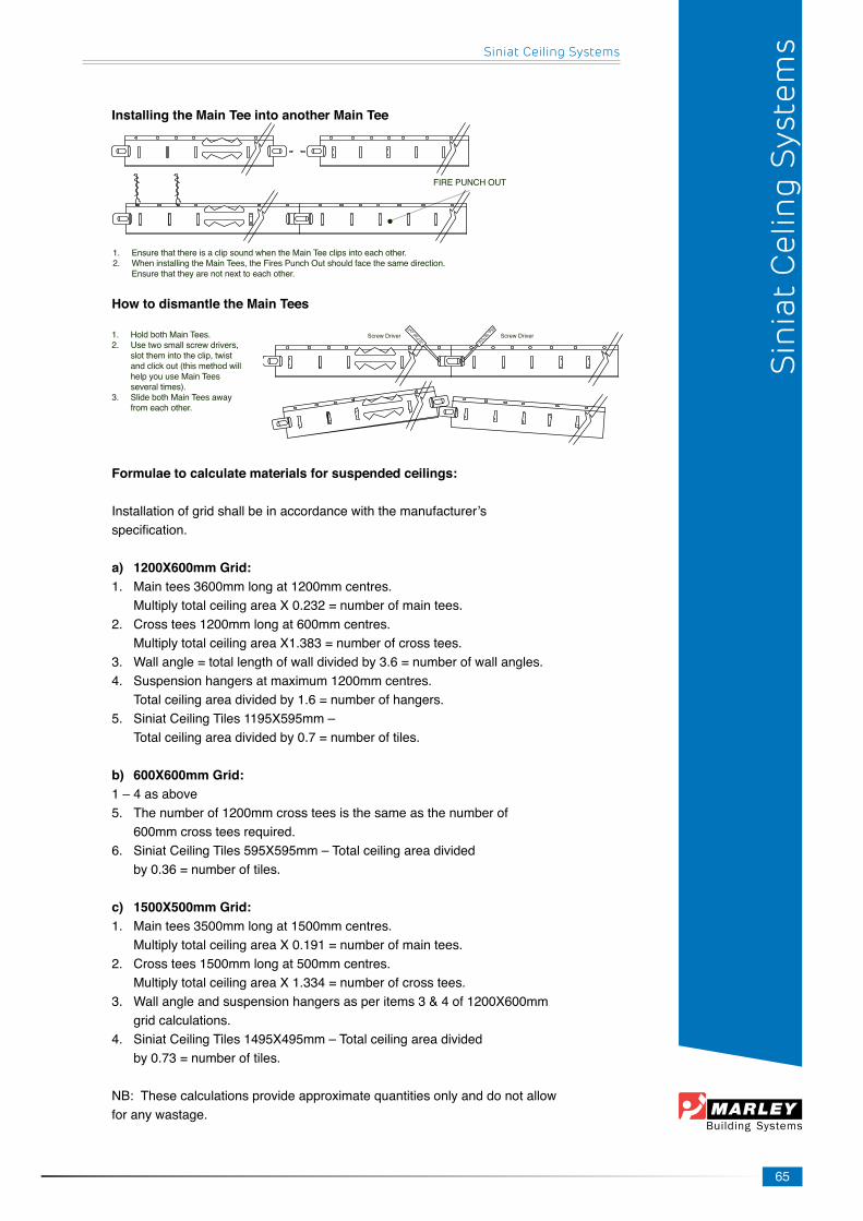
65
Siniat Ceiling Systems
Installing the Main Tee into another Main Tee
How to dismantle the Main Tees
1. HoldbothMainTees.2. Usetwosmallscrewdrivers, slotthemintotheclip,twist andclickout(thismethodwill helpyouuseMainTees severaltimes).3. SlidebothMainTeesaway fromeachother.
Formulae to calculate materials for suspended ceilings:
Installationofgridshallbeinaccordancewiththemanufacturer’sspecification.
a) 1200X600mm Grid:1. Maintees3600mmlongat1200mmcentres. MultiplytotalceilingareaX0.232=numberofmaintees.2. Crosstees1200mmlongat600mmcentres. MultiplytotalceilingareaX1.383=numberofcrosstees.3. Wallangle=totallengthofwalldividedby3.6=numberofwallangles.4. Suspensionhangersatmaximum1200mmcentres. Totalceilingareadividedby1.6=numberofhangers.5. SiniatCeilingTiles1195X595mm– Totalceilingareadividedby0.7=numberoftiles.
b) 600X600mm Grid:1–4asabove5. Thenumberof1200mmcrossteesisthesameasthenumberof 600mmcrossteesrequired.6. SiniatCeilingTiles595X595mm–Totalceilingareadivided by0.36=numberoftiles.
c) 1500X500mm Grid:1. Maintees3500mmlongat1500mmcentres. MultiplytotalceilingareaX0.191=numberofmaintees.2. Crosstees1500mmlongat500mmcentres. MultiplytotalceilingareaX1.334=numberofcrosstees.3. Wallangleandsuspensionhangersasperitems3&4of1200X600mm grid calculations.4. SiniatCeilingTiles1495X495mm–Totalceilingareadivided by0.73=numberoftiles.
NB:Thesecalculationsprovideapproximatequantitiesonlyanddonotallowforanywastage.
Sin
iat
Cel
ing
Sys
tem
s
1. EnsurethatthereisaclipsoundwhentheMainTeeclipsintoeachother.2. WheninstallingtheMainTees,theFiresPunchOutshouldfacethesamedirection. Ensurethattheyarenotnexttoeachother.
FIREPUNCHOUT
Screw DriverScrew Driver

66
Recommendations for the Suspension ofTee Systems
*Subjecttoloadingdetailsuspensionshouldnotnormallyexceed 1200mmcentres.• Themaximumlengthofaceilingwithouteitherasupportingpartition, movementjointorbreakshallnotbemorethan15m• Thesuspensionmustnotbeoutofplumb(vertical)morethan25mmfor each150mmofplenumdepth.• Wheneveraboveisexceededand/orwhenthehangersuspension ismorethan3000mmlongthenasubgridisrecommended.• Subgrid,whenused,shouldbeformedusingBurgessChannel. AlternativelypleasecontacttheSiniatTechnicalServicesDepartmentto discuss suspension options.• Innocaseshouldsuspensionbefromotherservicesintheceilingvoid.• Ahangersuspensionpointwithin300mmofthemainteejointmustbe installedwhenusinggridthathasfirepunchouts.• Ahangersuspensionpointwithin400mmfromthewallangleor shadowlineanglemustbeinstalledonmaintees.Wherecutcrosstees exceed600mmandrestonthecorniceadditionalsuspensionshouldbe installed.• Ifpoprivetsareused,theyshouldbesteelandnotaluminium.They shouldhaveashearstrength3timesthatofthemaximumallowedceiling load.• Whensecuringwiretoteeitshouldbewoundtightlyarounditselfatleast 3times.• Shouldtheceilingmassexceed20kg/m2andasubgridisrequired. Aconsultingengineershouldrecommendsuitablesuspension.
Installation of the Exposed Grid System:
Step 1 (setting out the grid):• Strikealevelchalklinearoundtheperimeteroftheroomatthehightat whichtheceilingistobefixed.(Waterlevelsandlaserlevelsarethe mostpopularmethods).• Fixthewallangleonthislineusingscrewsandplugs,orflutednails,at maximum400mmcentres(foratidyfinish).Thewallanglesshouldnot restontopofeachotheratthecorners.Mitreandbutt-joinforatidy finish.
Steel Sections
• Establishthecentreoftheroomandmarkontheoppositewallsofthe room.
Siniat Ceiling Systems
Sin
iat
Cel
ing
Sys
tem
s

67
Siniat Ceiling Systems
• Afterdeterminingthedirectioninwhichthetileswillbeinstalled,start fromthecentreofonewallandmarkat1200mmintervals,finishingwith equalspacingsattheadjoiningwalls.Repeattheprocedureonthe opposite wall.• Tomarktheroomintheotherdirection,startonthecentrelinepreviously markedandmarkthewallat600mmcentres,finishingwithequalspacing atoppositeendsoftheroom.Marktheoppositewallinthesame manner.• Oncethetiledirectionhasbeendeterminedthefirstmainteesshouldbe trimmedtoaccommodatethefirstrowoftilesandlastrowoftilessothat thespacingisequalonbothsidesoftheroom.
Step 2 (installing the grid):• Fixhangerstothestructurespacedatmaximum1.2mcentres.Tofix hangerstoaconcretesoffit,use25X25anglecleatsmadefrom1.6mm material.• Thehangerscaneitherbe25X25mmangle,19mmgalvanisedhanger strappingortherecommended2.5mmdiameterpre-strainedsuspension wire.Cuthangerwirestoalengththatallowsthemtohang approximately200mmbelowtheceilingplane.Thisallowsenoughwire totietothemaintees.(25X25mmgalvanisedangleisusedtobrace ceilinggridfromupwardairpressurewhererequired).• Spanfishlinesatvariouspositionsacrossthewidthoftheroominline withthebottomsurfaceofthewallangle.• AttachtheSiniatmainTeestothehangerswhichareat1200mm centres.Adjustthehangerssothatthefaceoftheteesectiontouches thefishlines.• Insertendsofcrossteesintorelevantmainteeslots.• Fit ceiling tiles to grid.• Shouldholddownclipsberequired,use2holddownclipsperboard sharing.• Allperimeterandcutboardsmustbesecuredwithholddownclips.
Step 3 (Checking the grid):• Checkthehangersforthegridarecorrectlyspacedandadequately securedtothemainstructure.• Checkthattheundersideofthegridisperfectlylevel.Ifnot,adjust accordingly.• Checkthatthegridisadequatelyreinforcedwherelightfittingsaretobe suspendedfromtheceilingandinstalladditionalhangerswhere necessary.
Sin
iat
Cel
ing
Sys
tem
s
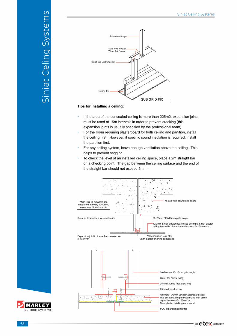
68
Siniat Ceiling Systems
Sin
iat
Cel
ing
Sys
tem
s
Tips for installing a ceiling:
• Iftheareaoftheconcealedceilingismorethan225m2,expansionjoints mustbeusedat15mintervalsinordertopreventcracking(this expansionjointsisusuallyspecifiedbytheprofessionalteam).• Fortheroomrequiringplasterboardforbothceilingandpartition,install theceilingfirst.However,ifspecificsoundinsulationisrequired,install thepartitionfirst.• Foranyceilingsystem,leaveenoughventilationabovetheceiling.This helps to prevent sagging.• Tocheckthelevelofaninstalledceilingspace,placea2mstraightbar onacheckingpoint.Thegapbetweentheceilingsurfaceandtheendof thestraightbarshouldnotexceed5mm.
SUB GRID FIX
Ceiling Tee
Siniat sub Grid Channel
GalvanisedAngle
Steel Pop Rivet orWaferTekScrew
20x20mm/25x25mmgalv.angle
12/9mmSiniatplasterboardfixedceilingtoSiniatplasterceilingteeswith25mmdrywallscrews@150mmc/c
rcslabwithdownstandbeam
Securedtostructuretospecification
PVCexpansionjointstripSkimplasterfinishingcompound
Maintees@1200mmc/csupportedatevery1200mm,crosstees@400mmc/c
Expansionjointinlinewithexpansionjointin concrete
20x20mm/25x25mmgalv.angle
Wafertekscrewfixing
35mmknurledfacegalv.tees
25mmdrywallscrew
12/9mm12/9mmSiniatPlasterboardfixedintoSiniatMastergridPlasterGridwith25mmdrywallscrews@150mmc/cSkimplasterfinishingcompound
PVCexpansionjointstrip
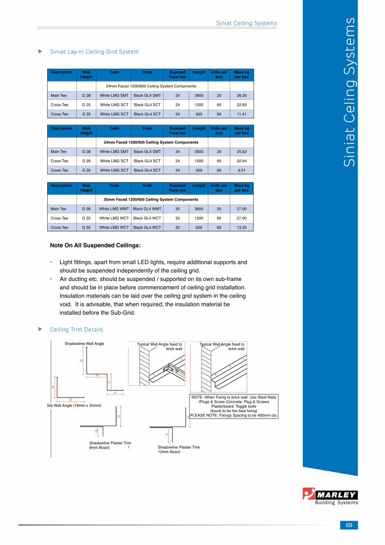
69
Siniat Ceiling Systems
Siniat Lay-in Ceiling Grid System
Note On All Suspended Ceilings:
• Lightfittings,apartfromsmallLEDlights,requireadditionalsupportsand shouldbesuspendedindependentlyoftheceilinggrid.• Airductingetc.shouldbesuspended/supportedonitsownsub-frame andshouldbeinplacebeforecommencementofceilinggridinstallation. Insulationmaterialscanbelaidovertheceilinggridsystemintheceiling void.Itisadvisable,thatwhenrequired,theinsulationmaterialbe installedbeforetheSub-Grid.
Ceiling Trim Details
Description Web Code Code Exposed Length Units per Mass kg Height Face mm box per box
35mm Faced 1200/600 Ceiling System Components
MainTee G38 WhiteLMGWMT BlackGL4WMT 35 3600 20 27.00
CrossTee G35 WhiteLMGWCT BlackGL4WCT 35 1200 60 27.00
CrossTee G35 WhiteLMGWCT BlackGL4WCT 35 600 60 13.50
Sin
iat
Cel
ing
Sys
tem
s
Description Web Code Code Exposed Length Units per Mass kg Height Face mm box per box
24mmFaced1200/600CeilingSystemComponents
MainTee G38 WhiteLMGSMT BlackGL4SMT 24 3600 20 26.35
CrossTee G35 WhiteLMGSCT BlackGL4SCT 24 1200 60 22.82
CrossTee G35 WhiteLMGSCT BlackGL4SCT 24 600 60 11.41
Description Web Code Code Exposed Length Units per Mass kg Height Face mm box per box
24mm Faced 1500/500 Ceiling System Components
MainTee G38 WhiteLMGSMT BlackGL4SMT 24 3500 20 25.62
CrossTee G35 WhiteLMGSCT BlackGL4SCT 24 1500 60 32.94
CrossTee G35 WhiteLMGSCT BlackGL4SCT 24 500 60 9.51
ShadowlineWallAngle
StdWallAngle(19mmx25mm)
ShadowlinePlasterTrim9mmBoard ShadowlinePlasterTrim
12mmBoard
NOTE:WhenFixingtobrickwall:UseSteelNails/Plugs&ScrewConcrete:Plug&Screws
Plasterboard: Toggle bolts (foundtobethebestfixing)
PLEASENOTE:FixingsSpacingtobe400mmcts.
TypicalWallAnglefixedtobrick wall
TypicalWallAnglefixedtobrick wall
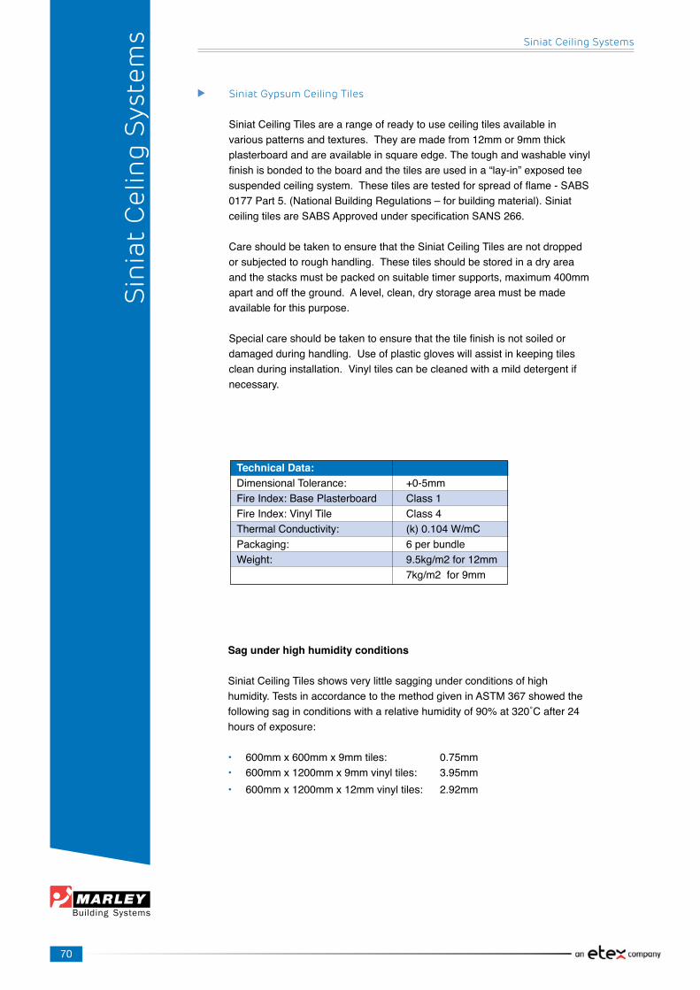
70
Siniat Ceiling Systems
Sin
iat
Cel
ing
Sys
tem
s
Siniat Gypsum Ceiling Tiles
SiniatCeilingTilesarearangeofreadytouseceilingtilesavailableinvariouspatternsandtextures.Theyaremadefrom12mmor9mmthickplasterboardandareavailableinsquareedge.Thetoughandwashablevinylfinishisbondedtotheboardandthetilesareusedina“lay-in”exposedteesuspendedceilingsystem.Thesetilesaretestedforspreadofflame-SABS0177Part5.(NationalBuildingRegulations–forbuildingmaterial).SiniatceilingtilesareSABSApprovedunderspecificationSANS266.
Care should be taken to ensure that the Siniat Ceiling Tiles are not dropped orsubjectedtoroughhandling.Thesetilesshouldbestoredinadryareaandthestacksmustbepackedonsuitabletimersupports,maximum400mmapartandofftheground.Alevel,clean,drystorageareamustbemadeavailableforthispurpose.
Specialcareshouldbetakentoensurethatthetilefinishisnotsoiledordamagedduringhandling.Useofplasticgloveswillassistinkeepingtilescleanduringinstallation.Vinyltilescanbecleanedwithamilddetergentifnecessary.
Technical Data:DimensionalTolerance: +0-5mmFire Index: Base Plasterboard Class 1FireIndex:VinylTile Class4ThermalConductivity: (k)0.104W/mCPackaging: 6perbundleWeight: 9.5kg/m2for12mm 7kg/m2for9mm
Sag under high humidity conditions
SiniatCeilingTilesshowsverylittlesaggingunderconditionsofhighhumidity.TestsinaccordancetothemethodgiveninASTM367showedthefollowingsaginconditionswitharelativehumidityof90%at320˚Cafter24hoursofexposure:
• 600mmx600mmx9mmtiles: 0.75mm• 600mmx1200mmx9mmvinyltiles: 3.95mm• 600mmx1200mmx12mmvinyltiles: 2.92mm

71
Siniat Ceiling Systems
Sin
iat
Cel
ing
Sys
tem
s
Siniat Mastergrid Ceiling Tiles
72
Siniat Ceiling Systems
Sin
iat
Cel
ing
Sys
tem
s
Specification: SiniatCeilingGridexposedface24mmgridsystemlay-invinylceilingtiles(9mm)
SiniatVinylCeilingTilesSupplyandinstallSiniatCeilingTilestoSiniatCeilingGridexposedface24mmgridsystemlay-invinylceilingtiles(9mm).ShellWhite,Fissured,Reef,tomanufacturer’sspecification.Installationtobeinaccordancewithmanufacturer’sspecificationsincludingSABISA(SouthAfricanBuildingInteriorSystemsAssociation)installationguidelines
Specification: SiniatCeilingGridexposedface35mmgridsystemlay-invinylceilingtiles(9mm)
SiniatVinylCeilingTilesSupplyandinstallSiniatCeilingTilestoSiniatCeilingGridexposedface35mmgridsystemlay-invinylceilingtiles(9mm).ShellWhite,Fissured,Reef,tomanufacturer’sspecification.Installationtobeinaccordancewithmanufacturer’sspecificationsincludingSABISA(SouthAfricanBuildingInteriorSystemsAssociation)installationguidelines
Specification: SiniatCeilingGridexposedface24mmgridsystemlay-invinylceilingtiles(12mm)
SiniatVinylCeilingTilesSupplyandinstallSiniatCeilingTilestoSiniatCeilingGridexposedface24mmgridsystemlay-invinylceilingtiles(12mm).ShellWhite,Fissured,Reef,tomanufacturer’sspecification.Installationtobeinaccordancewithmanufacturer’sspecificationsincludingSABISA(SouthAfricanBuildingInteriorSystemsAssociation)installationguidelines
Specification:SiniatCeilingGridexposedface35mmgridsystemlay-invinylceilingtiles(12mm)
SiniatVinylCeilingTilesSupplyandinstallSiniatCeilingTilestoSiniatCeilingGridexposedface35mmgridsystemlay-invinylceilingtiles(12mm).ShellWhite,Fissured,Reef,tomanufacturer’sspecification.Installationtobeinaccordancewithmanufacturer’sspecificationsincludingSABISA(SouthAfricanBuildingInteriorSystemsAssociation)installationguidelines
Specification:
Siniat Thermal Ceiling Tiles with Vinyl Face 15mm Styrene backing:SupplyandinstallSiniatThermalCeilingTilestoSiniatCeilingGridexposedface24mmgridsystemlay-invinylceilingtiles(9mm).ShellWhite,Fissured,tomanufacturer’sspecificationsincludingSABISA(SouthAfricanBuildingInteriorSystemsAssociation)installationguidelines
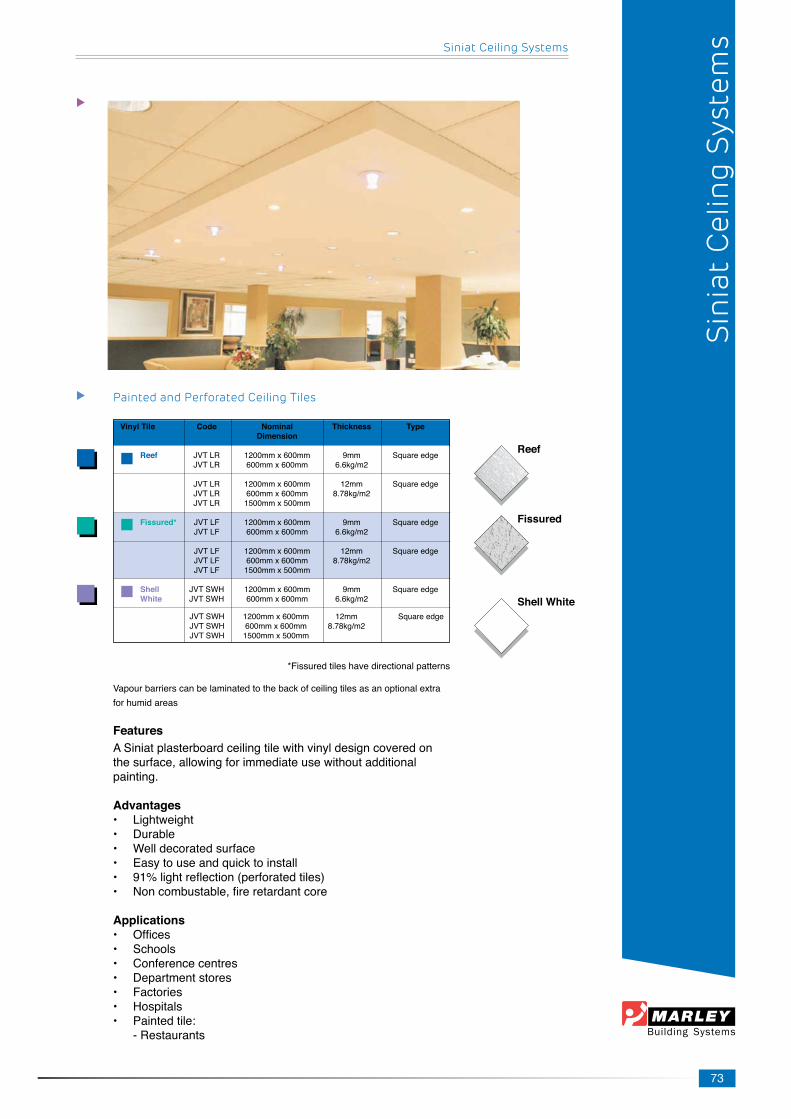
73
Siniat Ceiling Systems
*Fissured tiles have directional patterns
Vapourbarrierscanbelaminatedtothebackofceilingtilesasanoptionalextraforhumidareas
FeaturesASiniatplasterboardceilingtilewithvinyldesigncoveredonthesurface,allowingforimmediateusewithoutadditionalpainting.
Advantages• Lightweight• Durable• Welldecoratedsurface• Easytouseandquicktoinstall• 91%lightreflection(perforatedtiles)• Noncombustable,fireretardantcore
Applications• Offices• Schools• Conferencecentres• Departmentstores• Factories• Hospitals• Painted tile: - Restaurants
Vinyl Tile Code Nominal Thickness Type Dimension Reef JVTLR 1200mmx600mm 9mm Squareedge JVTLR 600mmx600mm 6.6kg/m2
JVTLR 1200mmx600mm 12mm Squareedge JVTLR 600mmx600mm 8.78kg/m2 JVTLR 1500mmx500mm
Fissured* JVTLF 1200mmx600mm 9mm Squareedge JVTLF 600mmx600mm 6.6kg/m2 JVTLF 1200mmx600mm 12mm Squareedge JVTLF 600mmx600mm 8.78kg/m2 JVTLF 1500mmx500mm
Shell JVTSWH 1200mmx600mm 9mm Squareedge White JVTSWH 600mmx600mm 6.6kg/m2
Painted and Perforated Ceiling Tiles
Reef
Fissured
Shell WhiteJVTSWH 1200mmx600mm 12mm SquareedgeJVTSWH 600mmx600mm 8.78kg/m2JVTSWH 1500mmx500mm
Sin
iat
Cel
ing
Sys
tem
s
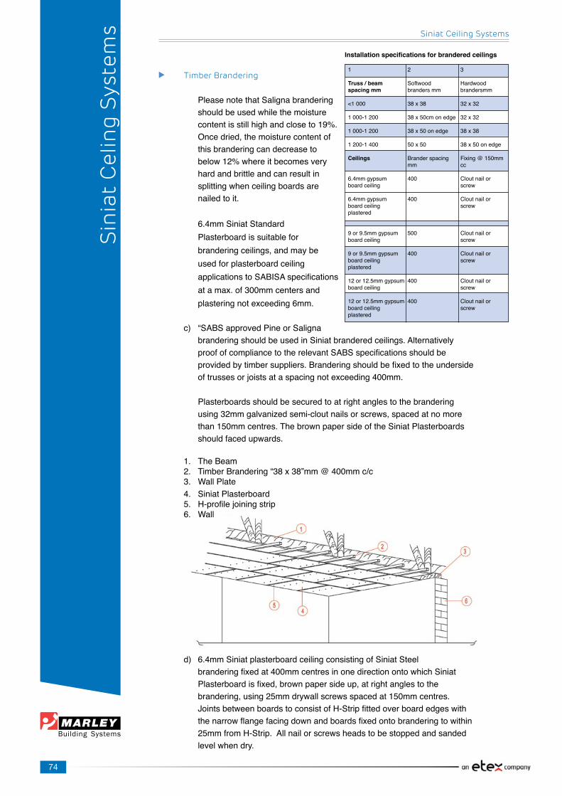
74
Siniat Ceiling Systems
Sin
iat
Cel
ing
Sys
tem
s
Timber Brandering
Please note that Saligna brandering shouldbeusedwhilethemoisture contentisstillhighandcloseto19%. Oncedried,themoisturecontentof this brandering can decrease to below12%whereitbecomesvery hard and brittle and can result in splitting when ceiling boards are nailed to it.
6.4mmSiniatStandard Plasterboardissuitablefor branderingceilings,andmaybe usedforplasterboardceiling applicationstoSABISAspecifications atamax.of300mmcentersand plasteringnotexceeding6mm.
c) “SABSapprovedPineorSaligna branderingshouldbeusedinSiniatbranderedceilings.Alternatively proofofcompliancetotherelevantSABSspecificationsshouldbe providedbytimbersuppliers.Branderingshouldbefixedtotheunderside oftrussesorjoistsataspacingnotexceeding400mm.
Plasterboards should be secured to at right angles to the brandering using32mmgalvanizedsemi-cloutnailsorscrews,spacedatnomore than150mmcentres.ThebrownpapersideoftheSiniatPlasterboards shouldfacedupwards.
1. TheBeam2. TimberBrandering“38x38”mm@400mmc/c3. WallPlate4. Siniat Plasterboard5. H-profilejoiningstrip6. Wall
d) 6.4mmSiniatplasterboardceilingconsistingofSiniatSteel branderingfixedat400mmcentresinonedirectionontowhichSiniat Plasterboardisfixed,brownpapersideup,atrightanglestothe brandering,using25mmdrywallscrewsspacedat150mmcentres. JointsbetweenboardstoconsistofH-Stripfittedoverboardedgeswith thenarrowflangefacingdownandboardsfixedontobranderingtowithin 25mmfromH-Strip.Allnailorscrewsheadstobestoppedandsanded levelwhendry.
1 2 3
Truss / beam Softwood Hardwoodspacing mm brandersmm brandersmm
<1000 38x38 32x32
1000-1200 38x50cmonedge 32x32
1000-1200 38x50onedge 38x38
1200-1400 50x50 38x50onedge
Ceilings Branderspacing Fixing@150mm mm cc
6.4mmgypsum 400 Cloutnailorboard ceiling screw
6.4mmgypsum 400 Cloutnailorboard ceiling screwplastered
9or9.5mmgypsum 500 Cloutnailorboard ceiling screw
9or9.5mmgypsum 400 Cloutnailorboard ceiling screwplastered
12or12.5mmgypsum 400 Cloutnailorboard ceiling screw
12or12.5mmgypsum 400 Cloutnailorboard ceiling screwplastered
Installation specifications for brandered ceilings

75
Siniat Ceiling Systems
Steel Brandering
1. TheBeam2. TimberBrandering“38x38”mm@400mmc/c3. WallPlate4. Siniat Plasterboard5. H-profilejoiningstrip6. Wall7. Suspension bracket
Steel Brandering should be installed as follows:
a) Steelbranderingsectionsmustbefixedat90°totherooftrusses.b) ThesuspensionbracketistobefixedtotheTie-beambyeithernailor screwatamaximumof1200mmcentresandlocatedintotheSiniat Steel Brandering.c) SiniatSteelBranderingistypicallyinstalledat400mmcentres.d) TheSiniatPlasterboardshouldbefixedat90°totheSiniat Steel Branderingi.e.paralleltotherooftrusses,withscrewsornailsspacedat amaximumof150mmcentres.e) TheSiniatSteelBranderingsystemisnotsuitableforplasteredceilings orfor9mmand12mmboardceilings.f) Tojointwosteelbranderinglengths,ajoinersectionmustbeused.g) Itisadvisabletofixa20X20mmsteelangletotheperimeterwallsasa supportfortheSiniat Steel Brandering and SiniatPlasterboardfixing, thiswillensureasolidbaseforcornicefixing.h) Lightfittingsmustbefixedtothebranderingorconduitnotinstalled directlyontotheboard.i) Undernocircumstancesshouldbranderingbecuttomakeroomfora lightfitting.
Sin
iat
Cel
ing
Sys
tem
s

76
Siniat Ceiling Systems
Sin
iat
Cel
ing
Sys
tem
s
Siniat 75mm Gypsum Cornice Detail
1. Longitudinalbrandering@400mmc/c2. CrossBrandering@parameters3. Siniat Plasterboard4. Siniat Cornice5. Fixing Point6. Plaster7. Wall
SiniatCoveCorniceconsistsofagypsumplastercoreencasedinpaper.Itisprimarilydesignedforuseasacorniceattheanglebetweenwallandceiling.Itiseasytocutandfixandissuitablefordecoration.TheSiniatCoveCorniceisavailableinlengthsof2.7m,3m,3.6mor4,2mandhasawidthof75mm.Themassperlinearmeteris0.72kg.
Performance:
• Fire Protection:Whenexposedtofire,SiniatCoveCornicebehavesin thesamewayasSiniatPlasterboard.
• Durability:SiniatCoveCornicehasthesamelifeexpectancyasa house/buildingundernormalconditions.Ifexcessmovementoftheroof structureisexpected,fixcornicetowallonly.
• Acoustic Properties:SiniatCoveCornicecanbeusedforsealingany airpathsaroundceilingperimetersthushelpingtomaintainsound insulationperformancefromroomtoroom.

77
Siniat Ceiling Systems
Plasterboardjointstohavesupportbehindwithplasterboardfixedat150mmcentresAlljointstobecoveredwithFibatape(doubleoverbuttjoints)andtheceilingthenplasteredwitha2-3mmplastercoatofSiniatSkim-LiteorSkim-Stoneplasterappliedaspermanufacturer’sinstructions.AlternativelySiniatFinishingCompoundcanbeusedtoplaster.
1. TheBeam2. SteelBrandering“38x38mm”@300mmc/c3. WallPlate4. Siniat Plasterboard5. Plastered Ceiling6. Wall7. Suspension bracket
Sin
iat
Cel
ing
Sys
tem
s
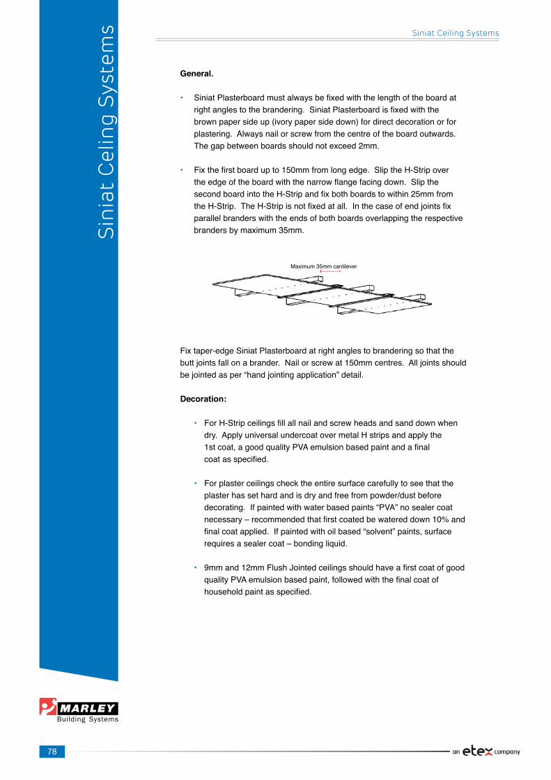
78
Siniat Ceiling Systems
Sin
iat
Cel
ing
Sys
tem
s
General.
• SiniatPlasterboardmustalwaysbefixedwiththelengthoftheboardat rightanglestothebrandering.SiniatPlasterboardisfixedwiththe brownpapersideup(ivorypapersidedown)fordirectdecorationorfor plastering.Alwaysnailorscrewfromthecentreoftheboardoutwards. Thegapbetweenboardsshouldnotexceed2mm.
• Fixthefirstboardupto150mmfromlongedge.SliptheH-Stripover theedgeoftheboardwiththenarrowflangefacingdown.Slipthe secondboardintotheH-Stripandfixbothboardstowithin25mmfrom theH-Strip.TheH-Stripisnotfixedatall.Inthecaseofendjointsfix parallelbranderswiththeendsofbothboardsoverlappingtherespective brandersbymaximum35mm.
Fix taper-edge Siniat Plasterboard at right angles to brandering so that the buttjointsfallonabrander.Nailorscrewat150mmcentres.Alljointsshouldbejointedasper“handjointingapplication”detail.
Decoration:
• ForH-Stripceilingsfillallnailandscrewheadsandsanddownwhen dry.ApplyuniversalundercoatovermetalHstripsandapplythe 1stcoat,agoodqualityPVAemulsionbasedpaintandafinal coatasspecified.
• Forplasterceilingschecktheentiresurfacecarefullytoseethatthe plasterhassethardandisdryandfreefrompowder/dustbefore decorating.Ifpaintedwithwaterbasedpaints“PVA”nosealercoat necessary–recommendedthatfirstcoatedbewatereddown10%and finalcoatapplied.Ifpaintedwithoilbased“solvent”paints,surface requiresasealercoat–bondingliquid.
• 9mmand12mmFlushJointedceilingsshouldhaveafirstcoatofgood qualityPVAemulsionbasedpaint,followedwiththefinalcoatof householdpaintasspecified.
Maximum35mmcantilever

79
Siniat Ceiling Systems
f) 9mm/12mmSiniatFlushJointedorFlushplasteredceiling consistingofgalvanisedplastergridscrew-up3600mmmainteesspaced at1200mmcentresand1200mmcrossteesspacedat400mmcentres, formingagalvanisedgrid,suspendedtomanufacturesspecification,onto which9mm/12mmtaper-edgeSiniatPlasterboardisfixedwithbrown papersideupusing25mmdrywallscrews,spacedat150mmcentres. Allplasterboardjointstohaveasupportbehind.Alljointsandorplasterto befinishedaspermanufacturersinstructions.
Grid Layout for Plastered Ceilings using 1200mm Cross T-Section
1. CrossT-Section1200mm@400c/c2. MainT-Section3600mm@1200c/c3. Suspension20x20/25x25GalvAngle@max1200mmc/c4. Concrete Slab5. Siniat9mm/12mmTaperEdgePlasterboard
Sin
iat
Cel
ing
Sys
tem
s

80
Siniat Ceiling Systems
Sin
iat
Cel
ing
Sys
tem
s
Siniat Mastergrid Suspended Plaster Grid
SiniatMastergridisasuspendedconcealedceilinggridsystemconsistingof3.6mmainteesand1.2mcrosstees.Crossteesareinsertedat400mmcentresinthemaintees.Theteesaregalvanisedsteelwithaknurled35mmface.Thisgridissuspendedusinggalvanisedangleensuringrigidityandstability.9mmor12mmboardsarescrewedtothegridusing25mmdrywallscrewsandthejointsaretapedandjointed.
Installing the Cross Tee into the Main Tee
Installing the Main Tee into another Main Tee
How to dismantlethe Main Tees
Screw Driver
Screw Driver
The Cross Tee is in position,showing ratchet position.
Ensurethattheclipfitsintoonesideoftheintermediatehole,oneintermediatecanslottwoclips.
Ensure that there is a clicking sound when the Cross Tee clips intotheMainTee.
TodismantletheCrossTeefromMainTee,youneedto:• Useasmallscrewdrivertopushthe clip back in.• SlowlypullouttheCrossTee horizontallyontheoneside.• Byusingascrewdriver,re-alignthe clipfromtheinsidebeforere-installing theCrossTeetotheMainTee.
NowclipintheCrossTee into the oppositesideoftheMainTee.
1. 2. 3.
4.
100MMINTERMEDIATESPACING
HANGERHOLES
PUNCHOUTCLIP
CROSSTEECLIPPINGINTOTHEMAINTEE
STEELCAPPING
1. EnsurethatthereisaclipsoundwhentheMainTeeclipsintoeachother.2. WheninstallingtheMainTees,theFiresPunchOutshouldfacethesamedirection. Ensurethattheyarenotnexttoeachother.
FIREPUNCHOUT
Screw DriverScrew Driver

81
Siniat Ceiling Systems
Siniat Plaster Grid System (Siniat Mastergrid)
Specification:
SupplyandinstallSiniatPlasterGrid,stitchedandgalvanised35mmfacesystem.Maintees3600mmwithslotsat400mmcentres.1200mmCrossTeeswithsteelgalvanisedknurledcapfacetomainandcrosstees.
Material calculations for Siniat Plaster Grid:
1. Maintees3600mmlongat1200mmcentres.Multiplytotalceilingarea X0.232=numberofmaintees.2. Crosstees1200mmlingat400mmcentres.Multiplytotalceilingarea X2.08=numberofcrosstees.3. ShadowlinePlastertrim=Totallengthofwalldividedby3.6=number ofshadowlineplastertrim.
Aluminium Sections
4. Suspensionhangersatmaximum1200mmcentres.Totalceilingarea dividedby1.6=numberofhangers.5. SiniatPlasterboardm2ofboarddividedintototalceilingarea=number ofboards.
Otheritemssuchasscrews,Fibatapeandjointingorfinishingcompoundshouldalsobeincluded,pleasecontactMarleyBuildingSystemsTechnicalServicesDepartmentforassistance.
Description Web Code Exposed Finish Length Units per Mass kg Height Face mm box per box MainTee G38 LMGPMT 35 Galvanised 3600 20 27.00
CrossTee G38 LMGPCT 35 Galvanised 1200 60 27.00
Plaster Ceiling JunctionDie6639
PlasterTrimAluminiumDie6640
Sin
iat
Cel
ing
Sys
tem
s
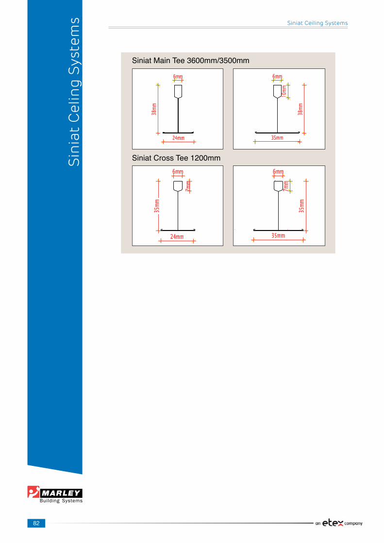
82
Siniat Ceiling Systems
Sin
iat
Cel
ing
Sys
tem
sSiniatMainTee3600mm/3500mm
SiniatCrossTee1200mm
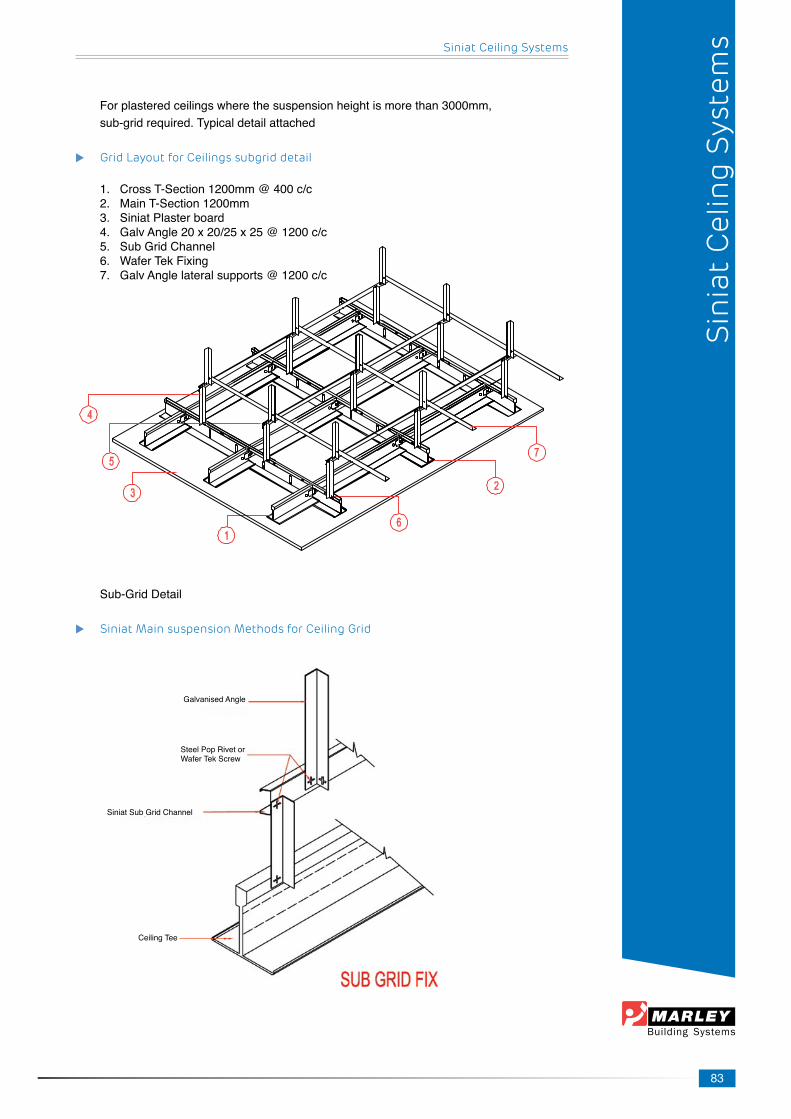
83
Siniat Ceiling Systems
Forplasteredceilingswherethesuspensionheightismorethan3000mm,sub-gridrequired.Typicaldetailattached
Grid Layout for Ceilings subgrid detail
1. CrossT-Section1200mm@400c/c2. MainT-Section1200mm3. Siniat Plaster board4. GalvAngle20x20/25x25@1200c/c5. Sub Grid Channel6. WaferTekFixing7. GalvAnglelateralsupports@1200c/c
Sub-Grid Detail
Siniat Main suspension Methods for Ceiling Grid
GalvanisedAngle
Steel Pop Rivet orWaferTekScrew
Siniat Sub Grid Channel
Ceiling Tee
Sin
iat
Cel
ing
Sys
tem
s

84
Siniat Ceiling Systems
Sin
iat
Cel
ing
Sys
tem
s
9mm & 12mm Flush Plastered Ceiling
9&12mmSiniatGypsumFireCheckflushplasteredceilingconsistingof galvanisedplastergridscrewup3600mmmainteesspacedat1200mm centres,fixedtosupportstructurewith0.8mmgalvanisedanglesspaced at400mmcentres,supportstructurespacedatmaximum1200mmand bracedtopreventlateralmovement,1200mmcrossteesspacedat 400mmcentres,formingagalvanisedgrid,suspendedtomanufactures specification.Plasterboardtobefixedat150mmcentres,withbrown papersideup.Staggerfixtoplasterboardjoints,firstlayerfixedwith 25mmdrywallscrews.Allplasterboardjointstohavesupportbehind. Insulationlayeroverceiling.Surfacetobeflushplastered.
Curved Ceilings
Siniat6.4mmStandardPlasterboardisrecommendedfortheconstructionofcurvedceilings.Theminimumradiusrecommendedis1000mm.Branderingspacingwillvarydependingonthecurvaturefrom150mmto400mm,butitshouldnotexceed400mm.Siniat6.4mmStandardPlasterboardsmustbeinstalledperpendiculartotheSiniatsteelbrandering.Siniat6.4mmStandardPlasterboardneedtobesecuredtoeachbranderwithSiniatdrywallscrewsnotmorethan150mmapart.
AlljointsbetweenboardsneedtobetapedwithFibaTapeandfinishedwithSiniatJointingPlaster.ItisrecommendedthatthecompletesurfacebeskimmedwithSiniatSkim-Litetoobtainasmoothcurvature.
Fire Rated Ceiling SystemsFire Rated Suspended Ceiling Systems
1. Burgesschannel1200mm@400mmcts2. TopHatsectionsat400mmctswithminimumthicknessof0.5mm3. Suspension25x25x0.8mmGalvAngle@max400mmcts4. Plaster to Ceilings5. Siniat15mmFireCheckTaperEdgePlasterboard6. 4,2x13WaterTekScrews2perjunction7. 14kg/m3100mmInsulation.8. BeamLateralSupport
• Beamsizeandspecificationsbyothers.• MaximumSuspension3m.• Beamlateralsupport@1200cts.
Plaster Grid
9/12mmSiniatPlasterboard
Fiba TapeSkimmingCompound

85
Siniat Ceiling Systems
Sin
iat
Cel
ing
Sys
tem
s
Board description
15mmFireCheck
15mmFireCheck
15mmFireCheck
Numberoflayers
Onelayer
TwoLayers
ThreeLayers
Fire Resistance
30minutes
60minutes
120minutes
Suspendedceilingtofireresistantwalljunction
Onlysidefixingisrecommendedanditisnotrecommendedthatfixingsthatrelyonpullforceisused.Thefollowingminimumanchorsarerecommendedforsidefixing:
Typeofrooftrussorfloorjoists
Systemswithuptotwolayersofboard
Systemswiththreelayersofboard
Steel including light weight steel
One5mmx20mmTekscrew
Two5mmx20mmTekscrews
Timber
One6mmx30mmchipboardscrew
Two6mmx50mmchipboardscrews
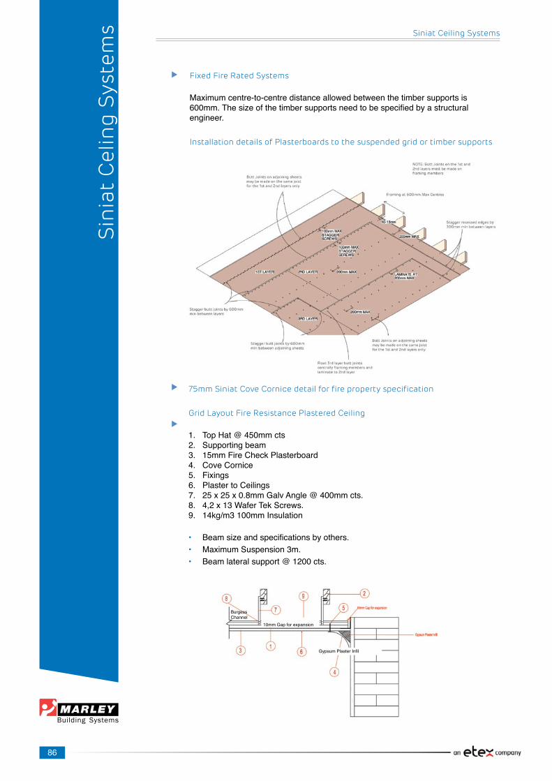
86
Fixed Fire Rated Systems
Maximumcentre-to-centredistanceallowedbetweenthetimbersupportsis600mm.Thesizeofthetimbersupportsneedtobespecifiedbyastructuralengineer.
Installation details of Plasterboards to the suspended grid or timber supports
Sin
iat
Cel
ing
Sys
tem
s
75mm Siniat Cove Cornice detail for fire property specification
Grid Layout Fire Resistance Plastered Ceiling
1. TopHat@450mmcts2. Supportingbeam3. 15mmFireCheckPlasterboard4. Cove Cornice5. Fixings6. PlastertoCeilings7. [email protected]. 4,2x13WaferTekScrews.9. 14kg/m3100mmInsulation
• Beamsizeandspecificationsbyothers.• MaximumSuspension3m.• Beamlateralsupport@1200cts.
10mmGapforexpansion
GypsumPlasterInfil
Siniat Ceiling Systems
BurgessChannel
87
Siniat XPS Decor Cornices
SiniatXPSDecorCornicesaremadeofhighdensitymouldedpolystyrene;thesemouldingsareextremelydurableandwillnotchipifdropped.Cutsanddentscanbefilledwithutilityadhesive,reducingwastesignificantly.
TheSiniatrangeofmouldingsiswaterandhumidityresistant,makingthemanexcellentchoiceforbathroomsandhumidareas.
Whiledirectheatplacedtooclosetomouldingscandamagethem,thelargerprofilescanbeusedtoconceallowvoltagefluorescentlightingwithaclearanceofapproximately5cm.NosolventbasedpaintoradhesivemustbeusedwiththeXPStypeofmouldings
Product Information:• Highdensitymouldedpolystyrene• Smoothwhitesurfacereadyforpainting• Availablein2mlengths• Meltingtemperatureis80°C• Non-toxic• Weightisapproximately8Kg/100m• PaintshouldbeacrylicwaterbasedPVApaint.Enamelpaintcanbeused butaprimerofPVApaintisrequired.
Storage Information:• The Siniat XPS Decor Cornices stored in cold or hot conditions should beallowedtostabilizetoambienttemperatureforabout24hoursinthe roomorsitebeforeinstallation.• Themouldingsshouldnotbestoredinshippingcontainersasthe temperaturesinsidecanexceed60°Cinsummer.• SiniatXPSDecorCornicesexpandandcontractwiththetemperature andmustbeinstalledtightly.
SINIAT CORNICE UTILITY ADHESIVE:Application:• Substratesmustbeclean,freeofdustandgrease.• Applyaliberalbeadofadhesivealongtopandbottomofcornice.• Pressfirmlytoholdinposition.• Wipeawayexcessadhesivewithadampspongeorcloth.• Keepawayfromfrost.
For fixing polystyrene and polyurethane:• Excellentadhesiveandfillingproperties.• Good initial grab.• Suitableforpainting.• Nofilmformation.
Characteristics:• Acrylicpolymer.• Highinitialtackandfinalbondstrength.• Excellent adhesion to paper and walls.• Flow properties designed as a paste to be applied with a scraper or spatula.
Siniat Ceiling Systems
Sin
iat
Cel
ing
Sys
tem
s

88
Specifications:• Consumption: 70-150gsm• GlueSpread: 50g/mforsmalltomediummouldingsonneworstraight walls. 100g/mforlargemouldingsonneworstraightwalls. 100g/mforsmalltomediummouldingsondamagedor uneven walls. 200g/mforlargemouldingsondamagedorunevenwalls.• SiniatCorniceUtilityAdhesiveisavailablein310mltubesand3kgand 7.5kg buckets.
Dilution of adhesive not recommended
Cleaning of equipment:• Cleanequipmentwithwaterbeforeadhesivedries.• Driedadhesivecanbemanuallybrushedorscrapedusinghotwater.
Storage:• Storebetween15°Cand30°Cunderdryconditions.• Unusedcontainersshouldbetightlysealed.• Shelflifeisapproximately12monthswhenstoredcorrectly.
PleasecontactMarleyBuildingSystemsforfirstaidmeasuresifrequired.
SiniatRoman
SiniatGrecian
SiniatClassic 80
Sin
iat
Cel
ing
Sys
tem
s Siniat Ceiling Systems

89
SiniatDoric
SiniatClassic 110
SiniatMilano
Siniat Ceiling Systems
Sin
iat
Cel
ing
Sys
tem
s
SiniatAthena
SiniatNapoli
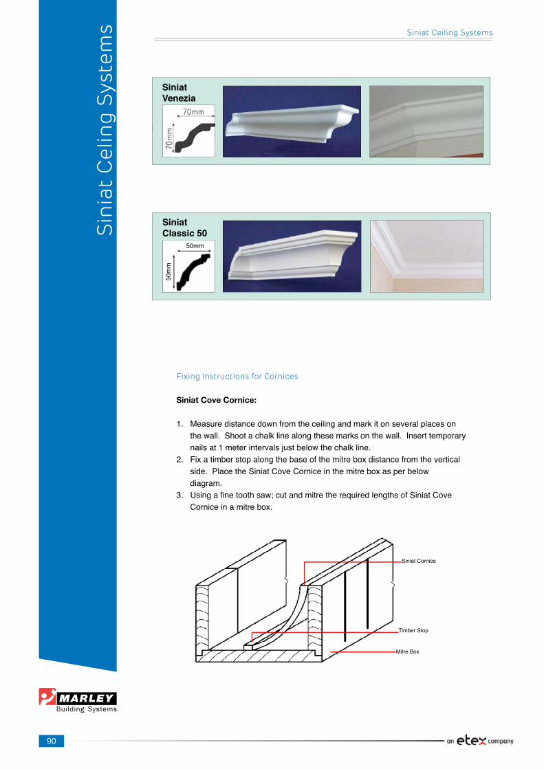
90
Fixing Instructions for Cornices
Siniat Cove Cornice:
1. Measuredistancedownfromtheceilingandmarkitonseveralplaceson thewall.Shootachalklinealongthesemarksonthewall.Inserttemporary nailsat1meterintervalsjustbelowthechalkline.2. Fixatimberstopalongthebaseofthemitreboxdistancefromthevertical side.PlacetheSiniatCoveCorniceinthemitreboxasperbelow diagram.3. Usingafinetoothsaw;cutandmitretherequiredlengthsofSiniatCove Corniceinamitrebox.
Siniat Cornice
TimberStop
MitreBox
Sin
iat
Cel
ing
Sys
tem
s Siniat Ceiling Systems
SiniatVenezia
SiniatClassic 50
50mm
50mm

91
4. GuidetheSiniatCoveCorniceoverthetemporarynailsandpress firmlyintopositionagainstthewallandceiling.Inserttemporarynailsinto ceilingtoholdcornice.Fixthecorniceat400mmintothewallandceiling usingsteelnailsordrill,plugandscrew.Onpaintedsurfacesawater- basedplasterbondingliquidshouldbeapplied.Patchimperfectionsand decorateasyouwouldplasterboard.Alternativelyfixthecornicewith suitable cornice adhesive.
NB: Always carry cornice on edge.Note:Cornicesarepurelydecorativeanddonotcontributeinanywaytothestructuralperformanceofabuilding.Ifexcessmovementoftheroofisexpected,fixcornicetothewallonly.Fillgapswithcorniceadhesivesuitableforpainting.
Siniat XPS Decor Cornices:
1. Measuredistancedownfromtheceilingandmarkitonseveralplaceson thewall.Shootachalklinealongthesemarksonthewall.Insert temporarynailsat1meterintervalsjustbelowthechalkline.2. Fixatimberstopalongthebaseofthemitreboxdistancefromthe verticalside.PlacetheSiniatDecorCorniceupsidedown(i.e. thebottomfacingupwards)inthemitrebox.PleaserefertotheSiniat DecorativeMouldingssectiontoensurethatyouhavethepatternthe correctwayup.3. SiniatDecorCornicesshouldbecutwithafinetoothedpanel saworfinehacksaw.Thiswillgiveacleanedgewithoutdamagingthe product.Donotcutwithaknifeorhotwire.Cutandmitretherequired lengthsofSiniatDecorCornicesinamitrebox.Ifusing patternedcornice,extremecaremustbetakentomatchthepattern whereajointoccurs.See“Preparingjointsandcornermitresofcornices” sectionforfurtherdetailsonhowtocutandmitre.TheSiniat DecorCornicestobeinstalledshouldnormallybecutslightly longerthanactuallengthrequiredtobeinstalled.Thisistogiveatightfit tothejoints.4. Spreadcorniceadhesivealongedgesandbackofmouldingandateach end.Useenoughadhesivesothattheentiresurfaceofthecutedgeat eachendiscovered.Alljointsmusthaveadequateadhesiveforastrong hold.5. GuidetheSiniatDecorCornicesoverthetemporarynailsand pressfirmlyintopositionagainstthewallandceiling.Themouldings mustbeinstalledonlevelandfirmsurfaces.Oncegluedontoceiling/ wall,fastenwithnails/screwsorpanelpinsespeciallyclosetothe jointsandedgesofthemouldingfortightandsecurefit.Mouldingsmust besecurelyfixedatalljoints.Shouldfixingsberequired,thenfixingsto beat300mmcentres.Largemouldingsrequiredadditionalsupporton eithertheverticalorhorizontalsurfacesforpositivefixing.
Painting Siniat XPS Decor Cornices:
• Polystyrenemouldingscanbepainteddirectlywithanyacrylicwater based paint. • PVApaintwouldberequiredbeforeapplyinganyenamelorsolvent based paint. • Themouldingswillturnyellowifleftunpainted.
Siniat Ceiling Systems
Sin
iat
Cel
ing
Sys
tem
s

92
• Itisadvisabletoapplyabasecoattothemouldingsbeforeinstallation.• Ensurethatadhesivetouch-upsaresandedleveltothemouldingprofile.• Painttechniquescanbeappliedtomouldingsbyspecialists.
Preparing Joints and Corner Mitres of Cornices
Types of corner mitres:Therearefourdifferenttypesofmitrecut:ExternalAngles–LefthandandRighthandInternalAngles–LefthandandRighthand.
Mitred Joints:
Tocutalefthandcornermitre,positionthemitreblocktotheleftofthelengthofcorniceandlineupthemeasuredmarkwiththeappropriatemitreblockslot(dependingonwhethertheangleistobeinternalorexternal).Similarly,positionthemitreblocktotherightofthelengthofcornicefortherighthandcorners.
BEFORE STARTING, NOTE WHICH WAY UP THE CORNICE SHOULD BE FITTED
Rememberthatallmarks,measurementsandcutsmustbemadefromthebackofthecornice’swalledge.Whenmeasuringformitresorbuttjoints,trytoensureagoodpatternmatchatthemeetingedges.Thisisespeciallyimportantwithexternalmitres,whicharegenerallymorevisible.So,wheneveramitreisrequired,measurethedistancebetweentheendofthelastfixedlengthandthecorneroftheroom.Markthismeasurementonthebackwalledgeofthenextlengthofcornice–makingsurethepatternmatchesateachpoint.
Cutting Cornice:
Whenusingthemitreblock,itisagoodideatokeepthecornicesupportedandlevelusingapieceofwoodthesamethicknessasthebaseofthemitreblock.Placethecorniceupside-downinthemitreblockwiththewalledgeuppermost,flatagainsttheside,andtheceilingedgeflatagainstthebase.
Siniat Cove Cornice
TimberStopMitreBox
LeftHandLeftHand
Right Hand Right Hand
InternalAngleExternalAngle
Measurefromendoflastlength to corner
Markthismeasurementonbackofthemoulding
Cutmouldingtothisdimension
Ceiling
AdhesiveMoulding
Fixing@300mmcentre
Fillfixingwithadhesive/fillerincludinggapsbetweenwallandmoulding
Typesofcornermitres:Therearefourdifferenttypesofmitrecut:ExternalAngles:LefthandandRighthandInternalAngles:LefthandandRightHand
Sin
iat
Cel
ing
Sys
tem
s Siniat Ceiling Systems
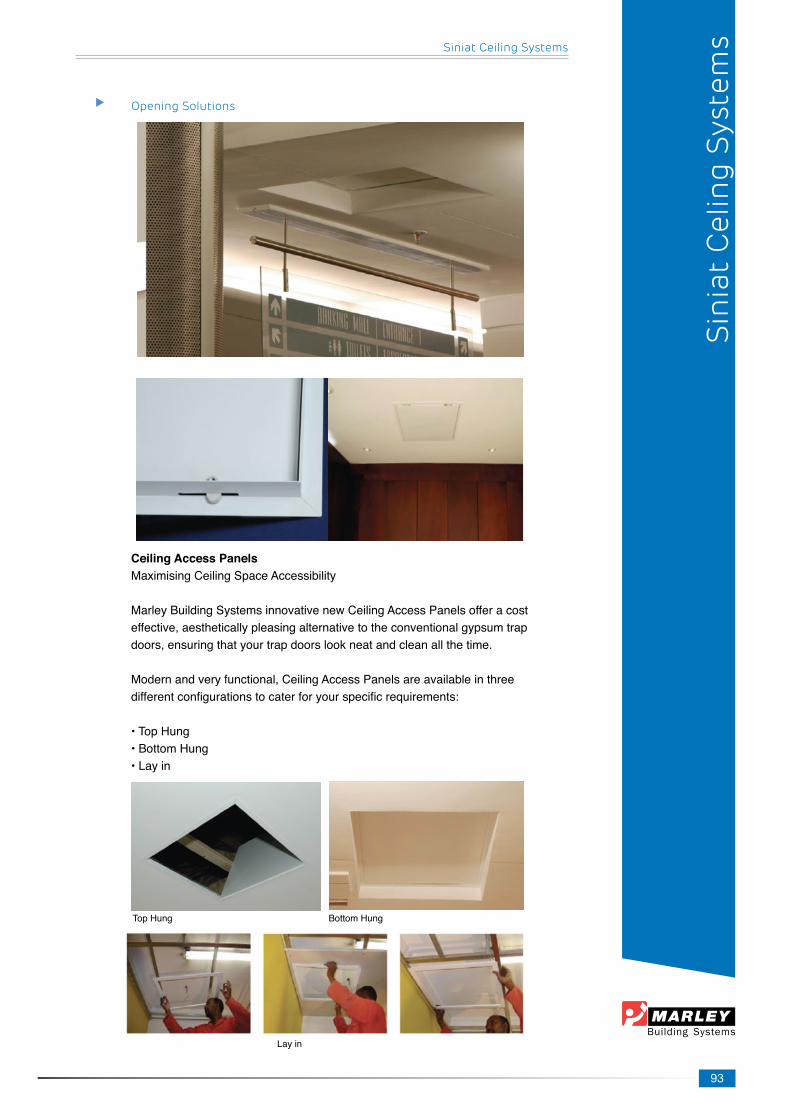
93
BottomHung
Opening Solutions
Ceiling Access PanelsMaximisingCeilingSpaceAccessibility
MarleyBuildingSystemsinnovativenewCeilingAccessPanelsofferacosteffective,aestheticallypleasingalternativetotheconventionalgypsumtrapdoors,ensuringthatyourtrapdoorslookneatandcleanallthetime.
Modernandveryfunctional,CeilingAccessPanelsareavailableinthreedifferentconfigurationstocaterforyourspecificrequirements:
• Top Hung•BottomHung•Layin
Top Hung
Layin
Siniat Ceiling Systems
Sin
iat
Cel
ing
Sys
tem
s
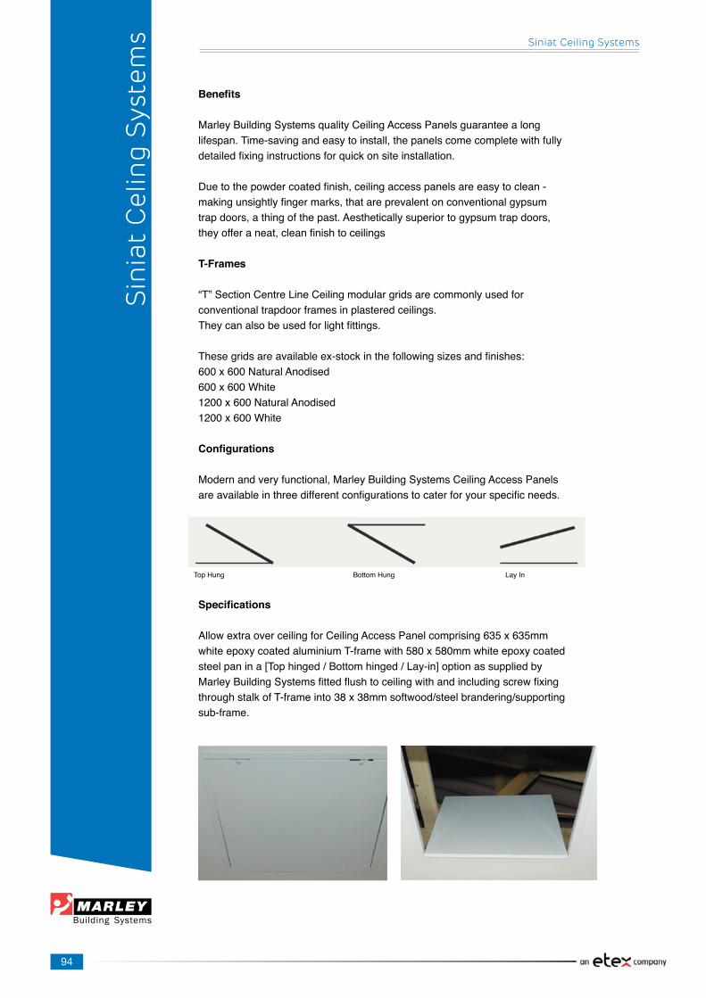
94
Benefits
MarleyBuildingSystemsqualityCeilingAccessPanelsguaranteealonglifespan.Time-savingandeasytoinstall,thepanelscomecompletewithfullydetailedfixinginstructionsforquickonsiteinstallation.
Duetothepowdercoatedfinish,ceilingaccesspanelsareeasytoclean-makingunsightlyfingermarks,thatareprevalentonconventionalgypsumtrapdoors,athingofthepast.Aestheticallysuperiortogypsumtrapdoors,theyofferaneat,cleanfinishtoceilings
T-Frames
“T”SectionCentreLineCeilingmodulargridsarecommonlyusedforconventionaltrapdoorframesinplasteredceilings.Theycanalsobeusedforlightfittings.
Thesegridsareavailableex-stockinthefollowingsizesandfinishes:600x600NaturalAnodised600x600White1200x600NaturalAnodised1200x600White
Configurations
Modernandveryfunctional,MarleyBuildingSystemsCeilingAccessPanelsareavailableinthreedifferentconfigurationstocaterforyourspecificneeds.
Specifications
AllowextraoverceilingforCeilingAccessPanelcomprising635x635mmwhiteepoxycoatedaluminiumT-framewith580x580mmwhiteepoxycoatedsteelpanina[Tophinged/Bottomhinged/Lay-in]optionassuppliedbyMarleyBuildingSystemsfittedflushtoceilingwithandincludingscrewfixingthroughstalkofT-frameinto38x38mmsoftwood/steelbrandering/supportingsub-frame.
Top Hung BottomHung LayIn
Siniat Ceiling Systems
Sin
iat
Cel
ing
Sys
tem
s
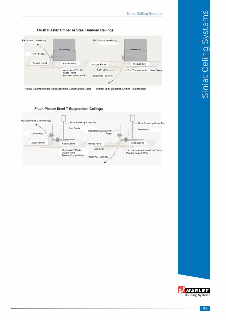
95
Flush Plaster Timber or Steel Branded Ceilings
Typical3DimensionalSteelBrandingConstructionDetailTypicalJointDetailfor6,4mmPlasterboard
Flush Plaster Steel T-Suspension Ceilings
Fixframetobrandering
TOPHINGED
AccessPanel Flush Ceiling
AluminiumT-ProfileOuterFramePowderCoatedWhite
Brandering
Fixframetobrandering
Brandering
Flush CeilingAccessPanel
BOTTOMHINGED
CamLock 25x25mmAluminiumOuterFrame
Galvanised25x25mmAngleSiniat Screw up Cross Tee
Pop Rivets
TOPHINGED
AccessPanel Flush Ceiling AccessPanel
CamLock
BOTTOMHINGED
Pop Rivets
Siniat Screw up Cross Tee
Flush Ceiling
25x25mmAluminiumOuterFramePowderCoatedWhite
AluminiumT-ProfileOuterFramePowderCoatedWhite
Galvanised25x25mmAngle
Siniat Ceiling Systems
Sin
iat
Cel
ing
Sys
tem
s

Head Office44 Industry Road, Clayville Ext 4, Olifantsfontein 1666
PO Box 127, Olifantsfontein, 1665Tel: (27 11) 316 2121
Fax: (27 11) 316 4138Web: www.marleybuildingsystems.co.za