Gwgk20lg - Gk Rc Modified
108
GWGK Lab Guide Overview This guide presents the instructions and other information concerning the lab activities for this course. You can find the solutions in the lab activity Answer Key. Outline This guide includes these activities: Lab Overview Lab 1-1: Implementing H.323 Gateways Lab 1-2: Implementing MGCP Gateways Lab 1-3: Implementing SIP Gateways Lab 2-1: Implementing Analog Trunks Lab 2-2: Implementing CAS Trunks Lab 2-3: Implementing PRI Trunks Lab 2-4: Implementing QSIG Trunks Lab 3-1: Implementing PSTN Dial Plans on Cisco IOS Gateways Lab 3-2: Implementing Multi-site Dial Plans on Cisco IOS Gateways Lab 3-3: Implementing RSVP-Based CAC Lab 3-4: Implementing Calling Privileges on Cisco IOS Gateways Lab 4-1: Implementing SRST Gateways Lab 4-2: Implementing Media Resources Using Cisco IOS Gateway DSPs Lab 4-3: Implementing Call Applications on Cisco IOS Gateways Lab 5-1: Implementing Basic Gatekeeper Functionali ty Lab 5-2: Implementing Gatekeeper-Based CAC Lab 5-3: Configuring Remote Zones Lab 5-4: Implementing Gatekeeper Redundancy Lab 6-1: Implementing IP-to-IP Gateways Answer Key
-
Upload
gilles-de-paimpol -
Category
Documents
-
view
215 -
download
0
Transcript of Gwgk20lg - Gk Rc Modified

7/27/2019 Gwgk20lg - Gk Rc Modified
http://slidepdf.com/reader/full/gwgk20lg-gk-rc-modified 1/107
GWGK
Lab Guide
Overview
This guide presents the instructions and other information concerning the lab activities for thiscourse. You can find the solutions in the lab activity Answer Key.
Outline
This guide includes these activities:
Lab Overview
Lab 1-1: Implementing H.323 Gateways
Lab 1-2: Implementing MGCP Gateways
Lab 1-3: Implementing SIP Gateways
Lab 2-1: Implementing Analog Trunks
Lab 2-2: Implementing CAS Trunks
Lab 2-3: Implementing PRI Trunks
Lab 2-4: Implementing QSIG Trunks
Lab 3-1: Implementing PSTN Dial Plans on Cisco IOS Gateways
Lab 3-2: Implementing Multi-site Dial Plans on Cisco IOS Gateways
Lab 3-3: Implementing RSVP-Based CAC
Lab 3-4: Implementing Calling Privileges on Cisco IOS Gateways
Lab 4-1: Implementing SRST Gateways
Lab 4-2: Implementing Media Resources Using Cisco IOS Gateway DSPs
Lab 4-3: Implementing Call Applications on Cisco IOS Gateways
Lab 5-1: Implementing Basic Gatekeeper Functionality
Lab 5-2: Implementing Gatekeeper-Based CAC
Lab 5-3: Configuring Remote Zones
Lab 5-4: Implementing Gatekeeper Redundancy
Lab 6-1: Implementing IP-to-IP Gateways
Answer Key

7/27/2019 Gwgk20lg - Gk Rc Modified
http://slidepdf.com/reader/full/gwgk20lg-gk-rc-modified 2/107
2 Implementing Cisco Voice Gateways and Gatekeepers (GWGK) v2.0 © 2006 Cisco Systems, Inc.
Lab OverviewThis topic describes the lab used throughout this Lab Guide.
Lab Topology
The figure shows the lab topology.
© 2006 Cisco Systems, Inc. All rights reserved. GWGK v2.0—3
Lab Topology
Phone2-1
2001
Phone2-2
2002
Router2(H.323)
Phone4-14001
Phone4-24002
Boston8575552XXX
Denver 3035554000
IP WAN
PSTNT1 PRI
T1 PRI T1 CAS
T1 QSIG
FXO/FXS
Phone1-11001
Phone1-21002
Router1(MGCP/SRST)
Site1CM1
Phone3-13001
Phone3-23002
San Jose4085551XXX
Chicago3125553XXX
GK
E&M
Site1CM2
Site2CM1
Site2CM2
Router4(CME)
Router3(CME)
GK = Gatekeeper
Lab SetupThe tables provide detailed information about router setup, IP addressing, accounts, passwords,
and phone numbers.

7/27/2019 Gwgk20lg - Gk Rc Modified
http://slidepdf.com/reader/full/gwgk20lg-gk-rc-modified 3/107
© 2006 Cisco Systems, Inc. Lab Guide 3
Routers and Interfaces
Device Interface Description
E1 0/0/0 E1 PRI trunk to PSTN:
ISDN switch type: primary-net5
Framing: CRC-4
Line code: HDB3
E1 0/0/1 E1 PRI trunk to Router2:
ISDN switch type: primary-qsig
Framing: CRC-4
Line code: HDB3
FastEthernet 0/0 LAN interface
Router 1 (San Jose)
FastEthernet 0/1 WAN interface
T1 0/1/0 T1 CAS trunk to PSTN:
ISDN switch type: primary-ni
Framing: ESF
Line code: B8ZS
E1 0/0/0 E1 PRI trunk to Router1:
ISDN switch type: primary-qsig
Framing: CRC4
Line code: HDB3
FastEthernet 0/0 LAN interface
Router 2 (Boston)
FastEthernet 0/1 WAN interface
E1 0/0/0 E1 PRI trunk to PSTN:
ISDN switch type: primary-net5
Framing: CRC-4
Line code: HDB3
FastEthernet 0/0 LAN interface
Router 3 (Chicago)
FastEthernet 0/1 WAN interface
FXO 0/0/0 Analog trunk to PSTN:
Signaling: ground start
FastEthernet 0/0 LAN interface
Router 4 (Denver)
FastEthernet 0/1 WAN interface
Gatekeeper (San Jose) FastEthernet 0/0 LAN interface

7/27/2019 Gwgk20lg - Gk Rc Modified
http://slidepdf.com/reader/full/gwgk20lg-gk-rc-modified 4/107
4 Implementing Cisco Voice Gateways and Gatekeepers (GWGK) v2.0 © 2006 Cisco Systems, Inc.
IP Addressing
Device IP Address
Site1CM1 192.168.P1.1/24
Site1CM2 192.168.P1.2/24
Phone1-1 192.168.P1.11/24
Phone1-2 192.168.P1.12/24
R1-SanJose (Router1) Fa0/0.111 (LAN): 192.168.P1.254/24
Fa0/0.116 (LAN): 192.168.P6.254/24
Fa0/1 (WAN): 192.168.P10.1/24
Site2CM1 192.168.P2.1/24
Site2CM2 192.168. P2.2/24
Phone2-1 192.168. P2.11/24
Phone2-2 192.168. P2.12/24
R2-Boston (Router2) Fa0/0.112 (LAN): 192.168. P2.254/24
Fa0/0.117 (LAN): 192.168.P7.254/24
Fa0/1 (WAN): 192.168. P10.2/24
Phone3-1 192.168. P3.11/24
Phone3-2 192.168. P3.12/24
R3-Chigago (Router3) Fa0/0 (LAN): 192.168.P3.254/24
Fa0/1 (WAN): 192.168. P10.3/24
Phone4-1 192.168. P4.11/24
Phone4-2 192.168. P4.12/24
R4-Denver (Router4) Fa0/0 (LAN): 192.168. P4.254/24
Fa0/1 (WAN): 192.168. P10.4/24
Gatekeeper Fa0/0 (LAN): 192.168. P1.3/24
SIP carrier (PSTN Router) Fa0/1 (WAN): 192.168. P10.254/24
Accounts and Passwords
Account Password
Windows Administrator: administrator cisco
Cisco Unified CallManager Administrator: administrator cisco
Telnet Password cisco
Enable Password cisco

7/27/2019 Gwgk20lg - Gk Rc Modified
http://slidepdf.com/reader/full/gwgk20lg-gk-rc-modified 5/107
© 2006 Cisco Systems, Inc. Lab Guide 5
Phone Numbers
Sites Range Extensions
San Jose 4085551XXX 1XXX
Boston 8575552XXX 2XXX
Chicago 3125553XXX 3XXX
Denver 3035554000 4XXX
San Jose PSTN phone 4085556666 NA
Boston PSTN phone 8575556666 NA
Chicago PSTN phone 3125556666 NA
Denver PSTN phone 3035556666 NA
Emergency calls 911 NA
U.S. Dialing Information
Description Pattern
PSTN access code 9
Local call 9 [2-9]XX XXXX
National call 9 1 [2-9]XX [2-9]XX XXXX
International call 9 011 variable length
Test number to dial in labs:
9 011 49 895556666
Emergency call 911
Note Calls from the PSTN phone are placed without dialing the PSTN access code. The dialing
information is only a subset of the U.S. dialing plan.

7/27/2019 Gwgk20lg - Gk Rc Modified
http://slidepdf.com/reader/full/gwgk20lg-gk-rc-modified 6/107
6 Implementing Cisco Voice Gateways and Gatekeepers (GWGK) v2.0 © 2006 Cisco Systems, Inc.
Lab 1-1: Implementing H.323 GatewaysComplete this lab activity to practice what you learned in the related module.
Activity Objective
In this activity, you will configure the Boston gateway router2 as an H.323 gateway and
integrate it with the Boston Cisco Unified CallManager cluster, including redundant CiscoUnified CallManager connections. After completing this activity, you will be able to meet these
objectives:
Configure a H.323 gateway to integrate with Cisco Unified CallManager
Add an H.323 gateway to Cisco Unified CallManager
Visual Objective
The figure illustrates what you will accomplish in this activity.
© 2006 Cisco Systems, Inc. All rights reserved. GWGK v2.0—4
Phone2-12001
Phone2-22002
Router2(H.323)
Phone4-14001
Phone4-24002
Boston8575552XXX
Denver 3035554000
IP WAN
PSTNT1 PRI
T1 PRI T1 CAS
T1 QSIG
FXO/FXS
Phone1-11001
Phone1-21002
Router1(MGCP/SRST)
Site1CM1
Phone3-13001
Phone3-23002
San Jose4085551XXX
Chicago3125553XXX
GK
E&M
Site1CM2
Site2CM1
Site2CM2
Visual Objective for Lab 1-1: ImplementingH.323 Gateways
Configure anH.323 gateway.
Configure a PSTNroute plan.
Router4(CME)
Router3(CME)
GK = Gatekeeper
Required Resources
These are the resources and equipment that are required to complete this activity: Boston Cisco Unified CallManager Site2CM1 and Site2CM2
Boston IOS gateway router2
Boston IP Phone

7/27/2019 Gwgk20lg - Gk Rc Modified
http://slidepdf.com/reader/full/gwgk20lg-gk-rc-modified 7/107
© 2006 Cisco Systems, Inc. Lab Guide 7
Command List
The table describes the commands that are used in this activity.
H.323 Gateway Configuration Commands
Command Description
voice service voip Enters voice-service-VoIP configuration mode
h323 Enables H.323 signaling for the VoIP service and entersH.323 configuration mode
h323-gateway voipinterface
Identifies the actual interface as a VoIP gateway interface
h323-gateway voip bind srcaddr ip-address
Sets the IP address that is used as an H.323 signalingsource
codec codec Specifies the codec used
show dial-peer voice tag Displays detailed information about the specified dial peer
show dial-peer voice
summary
Displays a summary of all active dial peers
debug voice dialpeer Displays default debug output for all active POTS dialpeers
debug voip dialpeer Displays default debug output for all active VoIP dial peers
debug h225 q931 Displays H.225 Q931 debug information
csim start called-number Initiates a test call using the gateway to verify call routing
Job Aids
These job aids are available to help you complete the lab activity:
Cisco IOS Voice Configuration Library Cisco Unified CallManager help pages

7/27/2019 Gwgk20lg - Gk Rc Modified
http://slidepdf.com/reader/full/gwgk20lg-gk-rc-modified 8/107
8 Implementing Cisco Voice Gateways and Gatekeepers (GWGK) v2.0 © 2006 Cisco Systems, Inc.
Task 1: Configure a H.323 Gateway to Integrate with CiscoUnified CallManager
In this task, you will configure the Cisco IOS gateway on the remote site Chicago to act as an
H.323 gateway for that location.
Activity Procedure
Complete these steps:
Step 1 On the Boston Cisco IOS gateway router2, ensure that H.323 is enabled.
Step 2 Configure two VoIP dial peers that point to the Boston Cisco Unified CallManager
cluster. Site2CM1 should be the active Cisco Unified CallManager, and Site2CM2
should be the standby. Use a destination pattern that matches the DID range in
Boston and configure the G.711 mu-law as the codec.
Step 3 Configure an H.323 voice class that sets the TCP-established timer for H.225
connections to 3 seconds and bind the class to both VoIP dial peers.
Step 4 Ensure that the LAN interface is the source interface for all H.323 packets.
Activity Verification
You have completed this task when you attain these results:
The show dial-peer voice summary command displays the two VoIP dial peers with the
correct preference.
Task 2: Add a H.323 Gateway to Cisco Unified CallManager
In this task, you will add the Boston H.323 gateway router2 to the Boston Cisco Unified
CallManager cluster.
Activity Procedure
Complete these steps:
Step 1 On the Boston Cisco Unified CallManager Site2CM1, access the Cisco Unified
CallManager Administration page.
Step 2 Add the Boston H.323 gateway router2 as a new H.323 gateway. Select the device
pool Default and ensure that only the last four digits are used for inbound calls.
Leave all other settings at the default values.
Step 3 Add a new route group BOS-PSTN-RG, which contains the Boston H.323 gateway
router2.
Step 4 Add a new route list BOS-PSTN-RL, which contains the route group BOS-PSTN-
RG.
Step 5 Add a new route pattern 9!# that points to the route list BOS-PSTN-RL. Do not
perform any digit manipulation.

7/27/2019 Gwgk20lg - Gk Rc Modified
http://slidepdf.com/reader/full/gwgk20lg-gk-rc-modified 9/107
© 2006 Cisco Systems, Inc. Lab Guide 9
Activity Verification
You have completed this task when you attain these results:
On router2, using the csim start 8575552001 command, a test call can be placed to phone
2-1 in Boston.
On router2, using the debug h225 q931 command will show the call information sent from
the Boston Cisco Unified CallManager to the gateway when a call is placed to the PSTN
from phone2-1.
Note Because no PSTN trunk has been configured yet, a successful call will not be possible.

7/27/2019 Gwgk20lg - Gk Rc Modified
http://slidepdf.com/reader/full/gwgk20lg-gk-rc-modified 10/107
10 Implementing Cisco Voice Gateways and Gatekeepers (GWGK) v2.0 © 2006 Cisco Systems, Inc.
Lab 1-2: Implementing MGCP GatewaysComplete this lab activity to practice what you learned in the related module.
Activity Objective
In this activity, you will configure the San Jose gateway router1 as an MGCP gateway and
integrate it with the San Jose Cisco Unified CallManager cluster. After completing this activity,you will be able to meet these objectives:
Add an MGCP gateway to Cisco Unified CallManager
Configure an MGCP gateway to integrate with Cisco Unified CallManager
Visual Objective
The figure illustrates what you will accomplish in this activity.
© 2006 Cisco Systems, Inc. All rights reserved. GWGK v2.0—5
Phone2-12001
Phone2-22002
Router2(H.323)
Phone4-14001
Phone4-24002
Boston8575552XXX
Denver
3035554000
IP WAN
PSTNT1 PRI
T1 PRI T1 CAS
T1 QSIG
FXO/FXS
Phone1-11001
Phone1-21002
Router1(MGCP/SRST)
Site1CM1
Phone3-13001
Phone3-23002
San Jose4085551XXX
Chicago3125553XXX
GK
E&M
Site2CM1
Site2CM2
Visual Objective for Lab 1-2: Implementing
MGCP Gateways
Configure anMGCP gateway.
Configure a PSTNroute plan.
Site1CM2
Router4(CME)
Router3(CME)
GK = Gatekeeper
Required Resources
These are the resources and equipment that are required to complete this activity:
Cisco Unified CallManager Site1CM1 and Site1CM2 in San Jose
Cisco IOS gateway router1 in San Jose
Physical T1 connection to the PSTN.
San Jose IP phones
PSTN IP phone

7/27/2019 Gwgk20lg - Gk Rc Modified
http://slidepdf.com/reader/full/gwgk20lg-gk-rc-modified 11/107
© 2006 Cisco Systems, Inc. Lab Guide 11
Command List
The table describes the commands that are used in this activity.
MGCP Commands
Command Description
ccm-manager config servercallmanager-ip-address
Specifies the Cisco Unified CallManager TFTP server thatwill be used by the gateway to download its configuration
ccm-manager config Activates the configuration download
mgcp bind control source-interface
Specifies the source interface that will be used for MGCPsignaling traffic
mgcp bind media source-interface
Specifies the source interface that will be used for MGCPmedia traffic
Job Aids
These job aids are available to help you complete the lab activity:
Cisco IOS Voice Configuration Library
Cisco Unified CallManager help pages
Task 1: Add a MGCP Gateway to Cisco Unified CallManager
In this task, you will add a new MGCP gateway to the Cisco Unified CallManager database and
route calls from the San Jose IP phones via that gateway. The MGCP gateway will be part of a
newly created route group on the Cisco Unified CallManager server.
Activity Procedure
Complete these steps:
Step 1 On the San Jose Cisco Unified CallManager Site1CM1, access the Cisco Unified
CallManager Administration page.
Step 2 Add the San Jose gateway router1 as an MGCP gateway.
Step 3 Configure the slot and the VWIC to match the router setup.
Step 4 Configure the E1 PSTN trunk as a E1 PRI. (E1 0/0/0)
Step 5 Choose device pool Default and make sure that only the last four digits of the
incoming called party number are used to match the phone extensions.
Step 6 Create a route group SJC-PSTN-RG. Place the newly created MGCP gatewayrouter1 in route group.
Step 7 Create a route list called SJC-PSTN-RL. Add the SJC-PSTN-RG route group to
the route list.
Step 8 Add a new route pattern 9.!# that points to the route list SJC-PSTN-RL. Ensure that
the PSTN access code 9 is stripped off, and use the external phone number mask for
the calling number when placing outbound calls.

7/27/2019 Gwgk20lg - Gk Rc Modified
http://slidepdf.com/reader/full/gwgk20lg-gk-rc-modified 12/107
12 Implementing Cisco Voice Gateways and Gatekeepers (GWGK) v2.0 © 2006 Cisco Systems, Inc.
Activity Verification
You have completed this task when you attain these results:
When searching for all patterns beginning with 9, the route plan report (Route Plan >
Route Plan Report) displays a route 9.!# pointing to the MGCP controlled T1 port of the
gwgk-router1 via the route list and route group.
Task 2: Configure an MGCP gateway to integrate with Cisco
Unified CallManager In this task, you will configure the San Jose gateway router1 to download its MGCP
configuration from the San Jose Cisco Unified CallManager TFTP server and register as an
MGCP gateway.
Activity Procedure
Complete these steps:
Step 1 On the San Jose gateway router1, ensure that the MGCP will use the LAN interface
as the source interface for media and control traffic.
Step 2 Specify the TFTP running on Site1CM1 as the configuration server.
Step 3 Activate the configuration download process.
Activity Verification
You have completed this task when you attain these results:
On the San Jose gateway router1, show isdn status shows that the Q.931 channel is
backhauled via Cisco Unified CallManager and the layer 2 status as
MULTIPLE_FRAME_ESTABLISHED.
Inbound and outbound PSTN calls at San Jose are possible.

7/27/2019 Gwgk20lg - Gk Rc Modified
http://slidepdf.com/reader/full/gwgk20lg-gk-rc-modified 13/107
© 2006 Cisco Systems, Inc. Lab Guide 13
Lab 1-3: Implementing SIP GatewaysComplete this lab activity to practice what you learned in the related module.
Activity Objective
In this activity, you will configure the Chicago Cisco Unified CallManager Express router3 to
route international calls via a SIP trunk to a SIP carrier. After completing this activity, you will be able to meet this objective:
Configure Cisco Unified CallManager Express with an SIP dial peer that will be used to
route calls to the SIP carrier
Visual Objective
The figure illustrates what you will accomplish in this activity.
© 2006 Cisco Systems, Inc. All rights reserved. GWGK v2.0—6
Phone2-12001
Phone2-22002
Router2(H.323)
Phone4-14001
Phone4-24002
Boston8575552XXX
Denver 3035554000
IP WAN
PSTN
T1 PRI
T1 PRI T1 CAS
T1 QSIG
FXO/FXS
Phone1-11001
Phone1-21002
Router1(MGCP/SRST)
Site1CM1
Phone3-13001
Phone3-23002
San Jose4085551XXX
Chicago3125553XXX
GK
E&M
Site1CM2
Site2CM1
Site2CM2
Visual Objective for Lab 1-3: ImplementingSIP Gateways
Configure an SIPtrunk to the PSTN.
Router4(CME)
Router3(CME)
GK = Gatekeeper
Required Resources
These are the resources and equipment that are required to complete this activity:
Chicago Cisco Unified CallManager Express router3. IP phone in Chicago
IP phone PSTN

7/27/2019 Gwgk20lg - Gk Rc Modified
http://slidepdf.com/reader/full/gwgk20lg-gk-rc-modified 14/107
14 Implementing Cisco Voice Gateways and Gatekeepers (GWGK) v2.0 © 2006 Cisco Systems, Inc.
Command List
The table describes the commands that are used in this activity.
SIP Configuration Commands
Command Description
voice service voip Enters VoIP configuration mode
sip Enables SIP signaling for the VoIP service and enters SIPconfiguration mode
session protocol sipv2 Specifies SIP to be the protocol used on the VoIP dial peer
show sip-ua calls Displays active SIP calls
Job Aids
These job aids are available to help you complete the lab activity:
Cisco IOS Voice Configuration Library.
Cisco Unified CallManager Express configuration guides
Task 1: Configure Cisco CallManager Express SIP Dial Peers
In this task, you will configure the Cisco CallManager Express in Chicago with an SIP dial peer
that will be used to route calls to the SIP carrier.
Activity Procedure
Complete these steps:
Step 1 On the Chicago Cisco Unified CallManager Express router3, enable SIP services.
Step 2 Create a new VoIP dial peer that points to the RouterPSTN WAN interface and a
destination pattern 0T. Use SIP as the session protocol.
Activity Verification
You have completed this task when you attain these results:
Using the Chicago phone3-1, you can place a call to 049895556666.
While a call from a Chicago phone to the PSTN is active, the show sip-ua calls command
on the Cisco Unified CallManager Express will display an active call.

7/27/2019 Gwgk20lg - Gk Rc Modified
http://slidepdf.com/reader/full/gwgk20lg-gk-rc-modified 15/107
© 2006 Cisco Systems, Inc. Lab Guide 15
Lab 2-1: Implementing Analog TrunksComplete this lab activity to practice what you learned in the related module.
Activity Objective
In this activity, you will configure an FXO PSTN trunk on the Denver Cisco Unified
CallManager Express router4. Because DID is not available, all inbound PSTN calls should berouted to the attendant with extension 4002. In addition, you will configure an E&M trunk to
route calls between Chicago router3 and Denver router4. After completing this activity, you
will be able to meet these objectives:
Configure an FXO trunk on a Cisco IOS gateway
Configure an E&M trunk on a Cisco IOS gateway
Visual Objective
The figure illustrates what you will accomplish in this activity.
© 2006 Cisco Systems, Inc. All rights reserved. GWGK v2.0—7
Phone2-12001
Phone2-22002
Router2(H.323)
Phone4-14001
Phone4-24002
Boston8575552XXX
IP WAN
PSTNT1 PRI
T1 PRI T1 CAS
T1 QSIG
FXO/FXS
Phone1-11001
Phone1-21002
Router1(MGCP/SRST)
Site1CM1
Phone3-13001
Phone3-23002
San Jose4085551XXX
Chicago3125553XXX
GK
E&M
Site1CM2
Site2CM1
Site2CM2
Visual Objective for Lab 2-1: ImplementingAnalog Trunks
Configure dialpeers for the E&Mand FXO trunks.
Configure anE&M trunk.
Configureincoming callsto be routed to
ext. 4002.
Configure the
FXO trunk.
Denver 3035554000
Router4(CME)
Router3(CME)
Configure dialpeers for theE&M trunk.
GK = Gatekeeper
7/27/2019 Gwgk20lg - Gk Rc Modified
http://slidepdf.com/reader/full/gwgk20lg-gk-rc-modified 16/107
16 Implementing Cisco Voice Gateways and Gatekeepers (GWGK) v2.0 © 2006 Cisco Systems, Inc.
Required Resources
These are the resources and equipment that are required to complete this activity:
Denver Cisco Unified CallManager Express router4 with an FXO PSTN connection and an
E&M connection to Chicago router3
Denver IP phones
PSTN IP phone
Chicago Cisco Unified CallManager Express router3 with an E&M connection to Denver router4
Chicago IP phones

7/27/2019 Gwgk20lg - Gk Rc Modified
http://slidepdf.com/reader/full/gwgk20lg-gk-rc-modified 17/107
© 2006 Cisco Systems, Inc. Lab Guide 17
Command List
The table describes the commands that are used in this activity.
Analog Voice Port Configuration Commands
Command Description
connection plar opx digits Directly routes a call from a voice port to the specifiednumber.
signal {groundStart |loopstart}
To specify the type of signaling for a voice port, use thesignal command in voice-port configuration mode. To resetto the default, use the no form of this command.
caller-id enable To allow the sending or receiving of caller-ID information,use the caller -id enable command in voice-portconfiguration mode at the sending FXS voice port or thereceiving FXO voice port. To disable the sending andreceiving of caller-ID information, use the no form of thiscommand.
E&M Configuration Commands
Command Description
type {1 | 2 | 3 | 4 | 5} To specify the E&M interface type, use the type commandin voice-port configuration mode. To reset to the default,use the no form of this command.
signal {delay-dial |immediate | lmr | wink-start}
To specify the type of signaling for a voice port, use thesignal command in voice-port configuration mode. To resetto the default, use the no form of this command.
Job Aids
This job aid is available to help you complete the lab activity:
Cisco IOS Voice Configuration Library
Task 1: Configure an FXO Trunk to the PSTN
In this task, you will configure Denver’s voice gateway for dialing into the PSTN. Incoming
calls will be routed to an attendant IP phone (ext. 4002)
Activity Procedure
Complete these steps:
Step 1 Configure the FXO PSTN trunk to use ground-start signaling.
Step 2 Create a new POTS dial peer with a destination pattern 9T to route outbound calls
using the FXO trunk. Verify that you can dial in to Denver using two-stage dialing.
Step 3 Ensure that any inbound call on the FXO trunk is routed directly to extension 4002.

7/27/2019 Gwgk20lg - Gk Rc Modified
http://slidepdf.com/reader/full/gwgk20lg-gk-rc-modified 18/107
18 Implementing Cisco Voice Gateways and Gatekeepers (GWGK) v2.0 © 2006 Cisco Systems, Inc.
Activity Verification
You have completed this task when you attain these results:
Denver outbound PSTN calls are possible.
Denver inbound PSTN calls ring the Denver phone with extension 4002.
Task 2: Configure an E&M Trunk Between Chicago and Denver
In this task, you will configure an E&M trunk between Chicago and Denver. Users should be
able to call remote site phones by simply dialing the extension.
Activity Procedure
Complete these steps:
Step 1 Configure the E&M port on Chicago router3 and Denver router4. Use wink-start
signaling and E&M type 1.
Step 2 On Chicago router3, add a new POTS dial peer 42 using the E&M port. Use a
destination pattern that matches the Denver extensions. Ensure that all required
digits are sent across the trunk. Use a preference of 2 for the dial peer.
Step 3 On Denver router4, add a new POTS dial peer 32 using the E&M port. Use a
destination pattern that matches the Chicago extensions. Ensure that all required
digits are sent across the trunk. Use a preference of 2 for the dial peer.
Activity Verification
You have completed this task when you attain these results:
Calls between Denver and Chicago are possible via the E&M trunk.

7/27/2019 Gwgk20lg - Gk Rc Modified
http://slidepdf.com/reader/full/gwgk20lg-gk-rc-modified 19/107
© 2006 Cisco Systems, Inc. Lab Guide 19
Lab 2-2: Implementing CAS TrunksComplete this lab activity to practice what you learned in the related module.
Activity Objective
In this activity, you will configure a T1 CAS trunk to the PSTN on the previously provisioned
Boston H.323 gateway router2. After completing this activity, you will be able to meet theseobjectives:
Configure a T1 CAS interface
Route calls using a T1 CAS interface
Visual Objective
The figure illustrates what you will accomplish in this activity.
© 2006 Cisco Systems, Inc. All rights reserved. GWGK v2.0—8
Visual Objective for Lab 2-2: Implementing
CAS Trunks
Phone2-12001
Phone2-22002
Router2(H.323)
Phone4-14001
Phone4-24002
Boston8575552XXX
Denver
3035554000
IP WAN
PSTNT1 PRI
T1 PRI T1 CAS
T1 QSIG
FXO/FXS
Phone1-11001
Phone1-21002
Router1(MGCP/SRST)
Site1CM1
Phone3-13001
Phone3-23002
San Jose4085551XXX
Chicago3125553XXX
GK
E&M
Site1CM2
Site2CM1
Site2CM2
Configure this lineas a CAS trunk with
E&M signaling.
Router4(CME)
Router3(CME)
GK = Gatekeeper
Required Resources
These are the resources and equipment that are required to complete this activity:
A phone at the PSTN
A Cisco Unified CallManager at the Boston site with a connected H.323 gateway and a
T1/E1 interface connected to the PSTN
An IP phone at the Boston site

7/27/2019 Gwgk20lg - Gk Rc Modified
http://slidepdf.com/reader/full/gwgk20lg-gk-rc-modified 20/107
20 Implementing Cisco Voice Gateways and Gatekeepers (GWGK) v2.0 © 2006 Cisco Systems, Inc.
Command List
The table describes the commands that are used in this activity.
T1 Interface Commands
Command Description
controller {t1 | e1}slot/subslot/port
Use the controller command in global configuration modeto configure a T1 or E1 controller and enter controller configuration mode.
framing {sf | esf} Use the framing command in controller configuration modeto select the frame type for the E1 or T1 data line.
linecode {ami | b8zs} Use the linecode command in controller configurationmode to select the line-code type for T1 or E1 lines.
clock source {[primary]line | internal | free-running}
Use the clock source command in controller configurationmode to set clocking for individual T1 or E1 links. To returnto the default, use the no form of this command.
network-clock-participate{aim | slot | wic} slot-
number
Use the network-clock-participate command in globalconfiguration mode to allow the ports on a specified
network module or VWIC to use the network clock for timing. To restrict the device to use only its own clocksignals, use the no form of this command.
ds0-group ds0-group-number timeslots <timeslot-list> type {e&m-delay-dial |e&m-fgd | e&m-immediate-start | e&m-wink-start |fxo-ground-start | fxo-loop-start | fxs-ground-start | fxs-loop-start}dtmf dnis
Use the ds0-group command in controller configurationmode to specify the DS0 time slots that make up a logicalvoice port on a T1 controller, to specify the signaling typeby which the router communicates with the PBX or PSTN,and to define T1 channels for compressed voice calls andthe CAS method by which the router connects to the PBXor PSTN. To remove the group and signaling setting, usethe no form of this command.
Job Aids
These job aids are available to help you complete the lab activity.
Cisco IOS Voice Command Reference
Cisco Interface Command Reference
Task 1: Configure a CAS Trunk to the PSTN
In this task, you will configure a CAS connection to the PSTN at Boston’s voice gateway for
dialing into the PSTN. The Boston gateway is already set up as an H.323 gateway so only themissing configuration needs to be added.

7/27/2019 Gwgk20lg - Gk Rc Modified
http://slidepdf.com/reader/full/gwgk20lg-gk-rc-modified 21/107
© 2006 Cisco Systems, Inc. Lab Guide 21
Activity Procedure
Complete these steps:
Step 1 Configure the T1 controller 0/1/0 of Boston’s gateway. Use ESF framing and B8ZS
line coding. Set the clock source to the PSTN. Then define a CAS group using all 24
channels with E&M immediate-start signaling.
Step 2 Configure the POTS dial peer 90 on Router2 using destination pattern 9T. Use the
voice port previously defined by the DS0 group. Make sure to strip the leading 9 before sending the call to the PSTN and that DID is enabled.
Activity Verification
You have completed this task when you attain these results:
You can verify connectivity by placing calls in both directions.
Inbound and outbound PSTN calls in Boston are possible.

7/27/2019 Gwgk20lg - Gk Rc Modified
http://slidepdf.com/reader/full/gwgk20lg-gk-rc-modified 22/107
22 Implementing Cisco Voice Gateways and Gatekeepers (GWGK) v2.0 © 2006 Cisco Systems, Inc.
Lab 2-3: Implementing PRI TrunksComplete this lab activity to practice what you learned in the related module.
Activity Objective
In this activity, you will configure an ISDN PRI trunk to the PSTN on the Chicago Cisco
Unified CallManager Express router3. After completing this activity, you will be able to meetthese objectives:
Configure the PRI controllers for correct signaling, framing, and timeslot association
Configure the correct ISDN switch type and ISDN serial interface settings
Visual Objective
The figure illustrates what you will accomplish in this activity.
© 2006 Cisco Systems, Inc. All rights reserved. GWGK v2.0—9
Phone2-12001
Phone2-22002
Router2(H.323)
Phone4-14001
Phone4-24002
Boston8575552XXX
Denver
3035554000
IP WAN
PSTNT1 PRI
T1 PRI T1 CAS
T1 QSIG
FXO/FXS
Phone1-11001
Phone1-21002
Router1(MGCP/SRST)
Site1CM1
Phone3-13001
Phone3-23002
San Jose4085551XXX
Chicago3125553XXX
GK
E&M
Site1CM2
Site2CM1
Site2CM2
Visual Objective for Lab 2-3: Implementing
PRI Trunks
Configure this lineas an ISDN PRI
trunk to the PSTN.
Configure this lineas an ISDN PRI
trunk to the PSTN.
Router4(CME)
Router3(CME)
GK = Gatekeeper
Required Resources
These are the resources and equipment that are required to complete this activity:
Router 3 running Cisco Unified CallManager Express in Chicago with an unconfigured PRItrunk
Phones in Chicago
PSTN phone

7/27/2019 Gwgk20lg - Gk Rc Modified
http://slidepdf.com/reader/full/gwgk20lg-gk-rc-modified 23/107
© 2006 Cisco Systems, Inc. Lab Guide 23
Command List
The table describes the commands that are used in this activity.
T1 Interface Commands
Command Description
isdn switch-type {country-
specific-switch-type}
Defines the telephone company switch type.
interface {bri | pri}interface-number
Enters interface configuration mode.
isdn incoming-voice voice To route all incoming voice calls to the modem anddetermine how they will be treated, use the isdnincoming-voice command in interface configuration mode.To disable the setting or return to the default, use the noform of this command.
pri-group timeslotstimeslot-range [nfas_d {backup | none | primary{nfas_int number |nfas_group number | rlm-group number }} | service]
To configure NFAS and specify the channels to becontrolled by the primary NFAS D channel, use the pri-group timeslots command in controller configurationmode.
network-clock-participate{aim | slot | wic} slot-number
Specifies which clock source to use for DSP clocking.
isdn protocol-emulate{user | network}
Defines Layer 2 and Layer 3 user- or network-sideemulation.
controller {t1 | e1}slot/subslot/port
Enters controller configuration mode.
framing {sf | esf | crc4 |nocrc4}
Defines the T1/E1 framing type
linecode {ami | b8zs |hdb3}
Defines linecoding
clear interface slot/port Resets the specified ISDN interface, which is required after a TEI configuration change.
telephony-service Enters Cisco Unified CallManager Express configurationmode.
dialplan-pattern tag pattern extension-lengthextension-length
Enables DID calls for Cisco Unified CallManager Expressephone-dns.
Job Aids
These job aids are available to help you complete the lab activity:
Cisco IOS Voice Command Reference
Cisco Interface Command Reference

7/27/2019 Gwgk20lg - Gk Rc Modified
http://slidepdf.com/reader/full/gwgk20lg-gk-rc-modified 24/107
24 Implementing Cisco Voice Gateways and Gatekeepers (GWGK) v2.0 © 2006 Cisco Systems, Inc.
Task 1: Configure an ISDN PRI Trunk to the PSTN in Chicago
In this task, you will configure an ISDN PRI trunk connection to the PSTN on Chicago’s voice
gateways for PSTN calls.
Activity Procedure
Complete these steps:
Step 1 On the Chicago Cisco Unified CallManager Express router3, ensure that the DSPs
are correctly clocked.
Step 2 Specify the correct global ISDN switch type. Use primary-net5.
Step 3 Configure the controller of the E1 PRI PSTN trunk (E1 0/0/0). Use all available time
slots.
Step 4 Configure the ISDN signaling interface for inbound voice calls.
Step 5 Add a new dial peer with a destination pattern 9T and DID enabled. Use the E1 PRI
PSTN trunk.
Step 6 Access the Cisco Unified CallManager Express configuration mode and configure adial plan pattern that enables DID calls to the Chicago DID range.
Step 7 Verify connectivity by placing calls in both directions.
Activity Verification
You have completed this task when you attain these results:
Calling in both directions works.
7/27/2019 Gwgk20lg - Gk Rc Modified
http://slidepdf.com/reader/full/gwgk20lg-gk-rc-modified 25/107
© 2006 Cisco Systems, Inc. Lab Guide 25
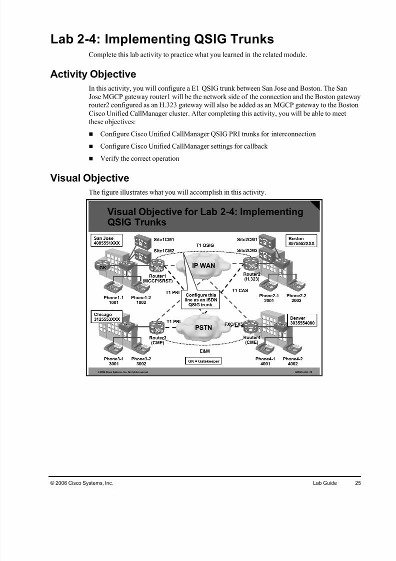
Lab 2-4: Implementing QSIG TrunksComplete this lab activity to practice what you learned in the related module.
Activity Objective
In this activity, you will configure a E1 QSIG trunk between San Jose and Boston. The San
Jose MGCP gateway router1 will be the network side of the connection and the Boston gatewayrouter2 configured as an H.323 gateway will also be added as an MGCP gateway to the Boston
Cisco Unified CallManager cluster. After completing this activity, you will be able to meet
these objectives:
Configure Cisco Unified CallManager QSIG PRI trunks for interconnection
Configure Cisco Unified CallManager settings for callback
Verify the correct operation
Visual Objective
The figure illustrates what you will accomplish in this activity.
© 2006 Cisco Systems, Inc. All rights reserved. GWGK v2.0—10
Phone2-12001
Phone2-22002
Router2(H.323)
Phone4-14001
Phone4-24002
Boston8575552XXX
Denver 3035554000
IP WAN
PSTNT1 PRI
T1 PRI
T1 CAS
T1 QSIG
FXO/FXS
Phone1-11001
Phone1-21002
Router1(MGCP/SRST)
Site1CM1
Phone3-13001
Phone3-23002
San Jose4085551XXX
Chicago3125553XXX
GK
E&M
Site1CM2
Site2CM1
Site2CM2
Visual Objective for Lab 2-4: ImplementingQSIG Trunks
Configure thisline as an ISDN
QSIG trunk.
Router4(CME)
Router3(CME)
GK = Gatekeeper

7/27/2019 Gwgk20lg - Gk Rc Modified
http://slidepdf.com/reader/full/gwgk20lg-gk-rc-modified 26/107
26 Implementing Cisco Voice Gateways and Gatekeepers (GWGK) v2.0 © 2006 Cisco Systems, Inc.
Required Resources
These are the resources and equipment that are required to complete this activity:
San Jose Cisco Unified CallManager cluster
San Jose MGCP gateway router1, already configured with the San Jose Cisco Unified
CallManager cluster
Boston Cisco Unified CallManager cluster
Boston H.323 gateway router2
San Jose IP phones
Boston IP phones
Command List
The table describes the commands that are used in this activity.
MGCP Configuration Commands
Command Description
ccm-manager config servercallmanager-ip-address
Specifies the Cisco Unified CallManager TFTP server thatwill be used by the gateway to download its configuration
ccm-manager config Activates the configuration download
mgcp bind control source-interface
Specifies the source interface that will be used for MGCPsignaling traffic
mgcp bind media source-interface
Specifies the source interface that will be used for MGCPmedia traffic
Job Aids
These job aids are available to help you complete the lab activity.
Cisco IOS Voice Command Reference
Cisco Interface Command Reference

7/27/2019 Gwgk20lg - Gk Rc Modified
http://slidepdf.com/reader/full/gwgk20lg-gk-rc-modified 27/107
© 2006 Cisco Systems, Inc. Lab Guide 27
Task 1: Configure a QSIG Trunk
In this task, you will configure an ISDN QSIG trunk connection between San Jose and Boston.
Activity Procedure
Complete these steps:
Step 1 On the San Jose Cisco Unified CallManager cluster, configure the second E1 PRI
(0/0/1) port on the already-configured San Jose MGCP gateway router1.
Step 2 Make sure that you select the network protocol side, internal clock source and QSIG
protocol.
Step 3 Configure a new route pattern, 2XXX, that points to the QSIG E1 port on the San
Jose MGCP gateway router1.
Step 4 On the Boston Cisco Unified CallManager cluster, configure the Boston gateway
router2 as an MGCP gateway. Make sure to only configure the QSIG E1 port
(0/0/0); otherwise, you might erase the already existing configuration.
Step 5 Select the QSIG as the protocol.
Step 6 Configure a new route pattern, 1XXX, which points to the QSIG E1 port on the
Boston MGCP gateway router1.
Step 7 On both Cisco Unified CallManager clusters, enable the callback service and add the
callback softkey to the softkey templates used by the phones.
Step 8 On the Boston H.323 gateway router2, enable configuration download for the
Boston Cisco Unified CallManager TFTP server on Site2CM1. Verify that the
gateway registers correctly.
Step 9 Verify that callback is working.
Activity Verification
You have completed this task when you attain these results:
Calls between San Jose and Boston are possible using the E1 QSIG connection.
Callback is working on the E1 QSIG connection.

7/27/2019 Gwgk20lg - Gk Rc Modified
http://slidepdf.com/reader/full/gwgk20lg-gk-rc-modified 28/107
28 Implementing Cisco Voice Gateways and Gatekeepers (GWGK) v2.0 © 2006 Cisco Systems, Inc.
Lab 3-1: Implementing PSTN Dial Plans on CiscoIOS Gateways
Complete this lab activity to practice what you learned in the related module.
Activity Objective
In this activity, you will implement a PSTN dial plan on the Boston H.323 gateway router2, on
the Chicago Cisco Unified CallManager Express router3 and on the Denver Cisco Unified
CallManager Express router4. After completing this activity, you will be able to meet these
objectives:
Configure dial peers for inbound and outbound PSTN routing
Configure voice-translation rules and profiles for correct ANI and DNI digit manipulation
Visual Objective
The figure illustrates what you will accomplish in this activity.
© 2006 Cisco Systems, Inc. All rights reserved. GWGK v2.0—11
Phone2-1
2001
Phone2-2
2002
Router2(H.323)
Phone4-14001
Phone4-24002
Boston8575552XXX
Denver 3035554000
IP WAN
PSTNT1 PRI
T1 PRI T1 CAS
T1 QSIG
FXO/FXS
Phone1-11001
Phone1-21002
Router1(MGCP/SRST)
Site1CM1
Phone3-13001
Phone3-23002
San Jose4085551XXX
Chicago3125553XXX
GK
E&M
Site1CM2
Site2CM1
Site2CM2
Configure aPSTN dial plan.
Configure aPSTN dial plan.
Configure aPSTN dial plan.
Visual Objective for Lab 3-1: ImplementingPSTN Dial Plans on Cisco IOS Gateways
Router4(CME)
Router3(CME)
GK = Gatekeeper
Required ResourcesThese are the resources and equipment that are required to complete this activity:
Boston Cisco IOS gateway router2
Chicago Cisco Unified CallManager Express router3
Chicago IP phones
Denver Cisco Unified CallManager Express router4
Denver IP phones

7/27/2019 Gwgk20lg - Gk Rc Modified
http://slidepdf.com/reader/full/gwgk20lg-gk-rc-modified 29/107
© 2006 Cisco Systems, Inc. Lab Guide 29
Command List
The tables describe the commands that are used in this activity.
Digit Manipulation Commands
Command Description
digit-strip Digit stripping strips all the digits that explicitly match a POTS dialpeer. Digit stripping is enabled by default on POTS dial peers.
prefix digits To specify the prefix of the dialed digits for a dial peer, use theprefix command in dial-peer configuration mode. To disable thisfeature, use the no form of this command.
forward-digits [0-32]|all|extra
To specify which digits to forward for voice calls, use theforward-digits command in dial-peer configuration mode.
num-exp dialed-digitssubstitution
To define how to expand a telephone extension number into aparticular destination pattern, use the num-exp command inglobal configuration mode. To cancel the configured number expansion, use the no form of this command.
voice translation-rule
rule tag
To define a translation rule for voice calls, use the voice
translation-rule command in global configuration mode. Todelete the translation rule, use the no form of this command.
rule precedence /match/ /replace/[type {match-typereplace-type} [plan{match-plan replace- plan}]]
To define a translation rule, use the rule command in voicetranslation-rule configuration mode. To delete the translation rule,use the no form of this command.
rule precedence reject/<match>/ [type match-type [plan match-type]]
To define a translation rule, use the rule command in voicetranslation-rule configuration mode. To delete the translation rule,use the no form of this command. You can also use a rule toreject a call by using the reject option.
voice translation- profile profile-name
To specify a translation profile for all incoming VoIP calls, use thevoip-incoming translation-profile command in globalconfiguration mode. To delete the profile, use the no form of thiscommand.
translate {called |calling | redirect-called} translation-rule-number
To associate a translation rule with a voice translation profile, usethe translate command in voice translation-profile configurationmode. To delete the translation rule from the profile, use the no form of this command.
translation-profile{incoming | outgoing}name
To assign a translation profile to a dial peer, use the translation-profile command in dial-peer configuration mode.
test voicetranslation-rule
number input-test-string [type match-type [plan match-type]
To test the functionality of a translation rule, use the test voicetranslation-rule command in privileged EXEC mode.

7/27/2019 Gwgk20lg - Gk Rc Modified
http://slidepdf.com/reader/full/gwgk20lg-gk-rc-modified 30/107
30 Implementing Cisco Voice Gateways and Gatekeepers (GWGK) v2.0 © 2006 Cisco Systems, Inc.
Call Routing and Path Selection Commands
Command Description
destination-pattern[+]string [T]
To specify either the prefix or the full E.164 telephone number tobe used for a dial peer, use the destination-pattern command indial-peer configuration mode. To disable the configured prefix or telephone number, use the no form of this command.
incoming called-number[+]string [T]
To specify a digit string that can be matched by an incoming callto associate the call with a dial peer, use the incoming called-number command in dial-peer configuration mode. To reset tothe default, use the no form of this command.
answer-address[+]string [T]
To specify the full E.164 telephone number to be used to identifythe dial peer of an incoming call, use the answer-address command in dial-peer configuration mode. To disable theconfigured telephone number, use the no form of this command.
direct-inward-dial Use the direct-inward-dial command to enable the DID calltreatment for an incoming called number.
preference [0-9] To indicate the preferred order of a dial peer within a hunt group,use the preference command in dial-peer configuration mode.
no dial-peer outbound
status-check pots
To check the status of outbound POTS dial peers during callsetup and to disallow, for that call, any dial peers whose status isdown, use the dial-peer outbound status-check pots commandin privileged EXEC mode. To disable status checking, use the no form of this command.
Job Aids
This job aid is available to help you complete the lab activity.
Voice configuration library on Cisco.com
Task 1: Configure Dial Peers for Inbound and Outbound PSTNRouting
In this task, you will configure dial peers for inbound and outbound PSTN routing on the
Boston H.323 gateway router2, Chicago Cisco Unified CallManager Express router3, and
Denver Cisco Unified CallManager Express router4.
Activity Procedure
Complete these steps:
Step 1 On the Boston H.323 gateway router2, Chicago Cisco Unified CallManager Express
router3, and Denver Cisco Unified CallManager Express router4, remove any
existing dial peer configuration used for PSTN routing.
Step 2 On the Boston H.323 gateway router2, Chicago Cisco Unified CallManager Expressrouter3, and Denver Cisco Unified CallManager Express router4, verify that the
controllers and voice ports are configured correctly.
Step 3 On the Boston H.323 gateway router2, configure this POTS dial peer:
All calls: dial peer 90, destination pattern 9T

7/27/2019 Gwgk20lg - Gk Rc Modified
http://slidepdf.com/reader/full/gwgk20lg-gk-rc-modified 31/107
© 2006 Cisco Systems, Inc. Lab Guide 31
Step 4 On the Chicago Cisco Unified CallManager Express router3, configure these dial
peers using the T1 PRI PSTN trunk:
Local calls: dial peer 90, destination pattern 9[2-9]XXXXXX, DID enabled
(ensuring that this dial peer is used for inbound PSTN calls)
National calls: dial peer 910, destination pattern 91[2-9]XX[2-9]XXXXXX
International calls: dial peer 90110, destination pattern 9011T
Emergency calls: dial peer 911, destination pattern 911 Emergency calls: dial peer 9911, destination pattern 9911
Note The X’s in the destination patterns are for ease of reading. They are not part of the actual
configuration syntax.
Step 5 On the Denver Cisco Unified CallManager Express router4, configure these dial
peers using the FXO PSTN trunk:
Local calls: dial peer 90, destination pattern 9[2-9]XXXXXX
National calls: dial peer 910, destination pattern 91[2-9]XX[2-9]XXXXXX
International calls: dial peer 90110, destination pattern 9011T
Emergency calls: dial peer 911, destination pattern 911
Emergency calls: dial peer 9911, destination pattern 9911
Note The X’s in the destination patterns are for ease of reading. They are not part of the actual
configuration syntax.
Activity Verification
You have completed this task when you attain these results:
You can place and receive PSTN calls in Boston.
You can place and receive PSTN calls in Chicago.
You can place and receive PSTN calls in Denver.
Task 2: Configure Voice-Translation Rules and Profiles for Correct ANI and DNIS Digit Manipulation
In this task, you will configure voice translation-rules and profiles for correct ANI and DNIS
on the Chicago Cisco Unified CallManager Express router3.
Activity Procedure
Complete these steps:
Step 1 On the Chicago Cisco Unified CallManager Express router3, configure a voice
translation profile pstn-in that performs these digit manipulations:
Any calling number with TON national should be prefixed with 9.

7/27/2019 Gwgk20lg - Gk Rc Modified
http://slidepdf.com/reader/full/gwgk20lg-gk-rc-modified 32/107
32 Implementing Cisco Voice Gateways and Gatekeepers (GWGK) v2.0 © 2006 Cisco Systems, Inc.
The called DID numbers 3125553XXX should be cut down to the four-digit
extension. For example, 3125553001 should be modified to 3001.
Step 2 Remove any existing dial plan pattern configuration
Step 3 Bind the voice translation profile pstn-in to the E1 PRI PSTN trunk. The profile
should be applied to incoming calls. Verify that inbound PSTN calls are working
again.
Step 4 Configure a voice-translation profile pstn-out that performs this digit manipulation: The calling number 3XXX should be prefixed with the Chicago DID range
312555. For example, if a call is placed from phone 3-1, the calling number
should be modified from 3001 to 3125553001.
Step 5 Bind the voice translation profile pstn-out to voice port 0/0/0:15. The ANI should
now be correctly modified to include the DID range for outgoing calls.
Activity Verification
You have completed this task when you attain these results:
Inbound calls to Chicago router 3 should be possible without the dialplan-pattern
command.
Inbound calls to Chicago router 3 include the 9 in the calling number. For example, a call
from the PSTN 13125556666 to Chicago phone 3-1 should be displayed as 913125556666.
Outbound calls from Chicago router 3 should have the calling number 3125553XXX.

7/27/2019 Gwgk20lg - Gk Rc Modified
http://slidepdf.com/reader/full/gwgk20lg-gk-rc-modified 33/107
© 2006 Cisco Systems, Inc. Lab Guide 33
Lab 3-2: Implementing Multisite Dial Plans onCisco IOS Gateways
Complete this lab activity to practice what you learned in the related module.
Activity Objective
In this activity, you will implement a multisite dial plan using site codes and toll-bypass WAN
routing with PSTN fallback routing between the Chicago Cisco Unified CallManager Express
router3 and the San Jose Cisco Unified CallManager cluster, and between the Chicago Cisco
Unified CallManager Express router3 and the Denver Cisco Unified CallManager Express
router4. After completing this activity, you will be able to meet these objectives:
Configure WAN with PSTN fallback routing between Chicago and San Jose
Configure WAN with PSTN fallback routing between Chicago and Denver
Visual Objective
The figure illustrates what you will accomplish in this activity.
© 2006 Cisco Systems, Inc. All rights reserved. GWGK v2.0—12
Phone2-12001
Phone2-22002
Router2(H.323)
Phone4-14001
Phone4-24002
Boston8575552XXX
Denver 3035554000
IP WAN
PSTNT1 PRI
T1 PRI T1 CAS
T1 QSIG
FXO/FXS
Phone1-11001
Phone1-21002
Router1(MGCP/SRST)
Site1CM1
Phone3-13001
Phone3-23002
San Jose4085551XXX
Chicago3125553XXX
GK
E&M
Site1CM2
Site2CM1
Site2CM2
Visual Objective for Lab 3-2: ImplementingMultisite Dial Plans on Cisco IOS Gateways
Configure intersiterouting to San
Jose and Denver.Configure intersiterouting to Chicago.
Configure intersiterouting to Chicago.
Router4(CME)
Router3(CME)
GK = Gatekeeper
Required Resources
These are the resources and equipment that are required to complete this activity:
Chicago Cisco Unified CallManager Express router3 with already-configured PSTN call
routing
Denver Cisco Unified CallManager Express router4 with already-configured PSTN call
routing

7/27/2019 Gwgk20lg - Gk Rc Modified
http://slidepdf.com/reader/full/gwgk20lg-gk-rc-modified 34/107
34 Implementing Cisco Voice Gateways and Gatekeepers (GWGK) v2.0 © 2006 Cisco Systems, Inc.
San Jose Cisco Unified CallManager cluster with already-configured San Jose MGCP
gateway router1
San Jose IP phones
Chicago IP phones
Denver IP phones
PSTN IP phone
Command List
The tables describe the commands that are used in this activity.
Digit Manipulation Commands
Command Description
prefix digits To specify the prefix of the dialed digits for a dial peer, use theprefix command in dial-peer configuration mode. To disable thisfeature, use the no form of this command.
forward-digits [0-32]|all|extra
To specify which digits to forward for voice calls, use theforward-digits command in dial-peer configuration mode.
voice translation-rulerule tag
To define a translation rule for voice calls, use the voicetranslation-rule command in global configuration mode. Todelete the translation rule, use the no form of this command.
rule precedence /match/ /replace/[type {match-typereplace-type} [plan{match-plan replace- plan}]]
To define a translation rule, use the rule command in voicetranslation-rule configuration mode. To delete the translation rule,use the no form of this command.
rule precedence reject/<match>/ [type match-
type [plan match-type]]
To define a translation rule, use the rule command in voicetranslation-rule configuration mode. To delete the translation rule,
use the no form of this command. You can also use a rule toreject a call with the reject option.
voice translation- profile profile-name
To specify a translation profile for all incoming VoIP calls, use thevoip-incoming translation-profile command in globalconfiguration mode. To delete the profile, use the no form of thiscommand.
translate {called |calling | redirect-called} translation-rule-number
To associate a translation rule with a voice translation profile, usethe translate command in voice translation-profile configurationmode. To delete the translation rule from the profile, use the no form of this command.
translation-profile{incoming | outgoing}name
To assign a translation profile to a dial peer, use the translation-profile command in dial-peer configuration mode.

7/27/2019 Gwgk20lg - Gk Rc Modified
http://slidepdf.com/reader/full/gwgk20lg-gk-rc-modified 35/107
© 2006 Cisco Systems, Inc. Lab Guide 35
Call Routing and Path Selection Commands
Command Description
destination-pattern[+]string [T]
To specify either the prefix or the full E.164 telephone number tobe used for a dial peer, use the destination-pattern command indial-peer configuration mode. To disable the configured prefix or telephone number, use the no form of this command.
preference [0-9] To indicate the preferred order of a dial peer within a hunt group,use the preference command in dial-peer configuration mode.
voice class h323 tag To create an H.323 voice class that is independent of a dial peer and can be used on multiple dial peers, use the voice classh323 command in global configuration mode. To remove thevoice class, use the no form of this command.
h225 timeout tcpestablish seconds
To set the H.225 TCP timeout value for VoIP dial peers, use theh225 timeout tcp establish command in voice-classconfiguration mode. To reset to the default, use the no form of this command.
Job Aids
This job aid is available to help you complete the lab activity.
Voice configuration library on Cisco.com
Task 1: Configure WAN with PSTN Fallback Routing BetweenChicago and San Jose
In this task, you will configure WAN routing between the Chicago Cisco Unified CallManager
Express router3 and the San Jose Cisco Unified CallManager cluster, including PSTN fallback
routing.
Activity Procedure
Complete these steps:
Step 1 On the Chicago Cisco Unified CallManager Express router3, configure these dial
peers and configure the H.225 TCP timeout timer:
Dial peer 10, destination pattern 1XXX, Site1CM1 IP, preference 0, codec
G.711ulaw
Dial peer 11, destination pattern 1XXX, Site1CM2 IP, preference 1, codec
G.711ulaw
Dial peer 12, destination pattern 1XXX, PSTN PRI trunk, preference 2
Step 2 Tune the dial peer 12 to prefix the San Jose DID range. Include the national
identifier 1. For example, 1001 should be modified to 14085551001
Step 3 Use the LAN interface as the H.323 interface.
Step 4 Tune the H.225 TCP established timer to 3 seconds when using the dial peers 10 and
11 pointing to the San Jose Cisco Unified CallManager cluster.
Step 5 On the San Jose Cisco Unified CallManager cluster, configure a non-gatekeeper-
controlled intercluster trunk pointing to the Chicago Cisco Unified CallManager
Express router3.
Step 6 Add a route pattern to route calls to Chicago, using the intercluster trunk to Chicago:

7/27/2019 Gwgk20lg - Gk Rc Modified
http://slidepdf.com/reader/full/gwgk20lg-gk-rc-modified 36/107
36 Implementing Cisco Voice Gateways and Gatekeepers (GWGK) v2.0 © 2006 Cisco Systems, Inc.
Activity Verification
You have completed this task when you attain these results:
You can place a call from Chicago to San Jose by dialing the San Jose extensions
You can place a call from Chicago to San Jose even if the WAN path is not available.
You can place a call from San Jose to Chicago by dialing the Chicago extension.
Task 2: Configure WAN with PSTN Fallback Routing BetweenChicago and Denver
In this task, you will configure WAN routing between the Chicago Cisco Unified CallManager
Express router3 and the Denver Cisco Unified CallManager Express router4, including PSTN
fallback routing.
Activity Procedure
Complete these steps:
Step 1 On the Chicago Cisco Unified CallManager Express router3, configure these dial
peers:
Dial peer 40, destination pattern 4XXX, Denver Cisco Unified CallManager
Express router4 IP, preference 0
Dial peer 41, destination pattern 4XXX, PSTN PRI trunk, preference 1
Step 2 Tune the dial peer 41 to prefix the Denver DID range. Include the national identifier
1. For example, 4001 should be modified to 13035554001.
Step 3 On the Denver Cisco Unified CallManager Express router4, configure these dial
peers:
Dial peer 30, destination pattern 3XXX, Chicago Cisco Unified CallManager
Express router3 IP, preference 0
Dial peer 31, destination pattern 3XXX, PSTN FXO trunk, preference 1
Step 4 Tune the dial peer 31 to prefix the Chicago DID range. Include the national
identifier 1. For example, 3001 should be modified to 13125553001.
Step 5 Use the LAN interface as the H.323 source interface.
Activity Verification
You have completed this task when you attain these results:
You can place a call from Chicago to Denver by dialing the Denver extension.
You can place a call from Chicago to Denver even if the WAN path is not available.
You can place a call from Denver to Chicago by dialing the Chicago extension.
You can place a call from Denver to Chicago even if the WAN path is not available.

7/27/2019 Gwgk20lg - Gk Rc Modified
http://slidepdf.com/reader/full/gwgk20lg-gk-rc-modified 37/107
© 2006 Cisco Systems, Inc. Lab Guide 37
Lab 3-3: Implementing RSVP-Based CACComplete this lab activity to practice what you learned in the related module.
Activity Objective
In this activity, you will implement RSVP-based CAC between the Chicago Cisco Unified
CallManager Express router3 and the Denver Cisco Unified CallManager Express router4.After completing this activity, you will be able to meet this objective:
Configure RSVP-based CAC on Cisco IOS gateways for VoIP calls
Visual Objective
The figure illustrates what you will accomplish in this activity.
© 2006 Cisco Systems, Inc. All rights reserved. GWGK v2.0—13
Phone2-12001
Phone2-22002
Router2(H.323)
Phone4-14001
Phone4-24002
Boston8575552XXX
Denver 3035554000
IP WAN
PSTNT1 PRI
T1 PRI T1 CAS
T1 QSIG
FXO/FXS
Phone1-11001
Phone1-21002
Router1(MGCP/SRST)
Site1CM1
Phone3-13001
Phone3-23002
San Jose4085551XXX
Chicago3125553XXX
GK
E&M
Site1CM2
Site2CM1
Site2CM2
Visual Objective for Lab 3-3: ImplementingRSVP-Based CAC
Configure RSVP-based CAC.
Router4(CME)
Router3(CME)
Configure RSVP-based CAC.
GK = Gatekeeper
Required Resources
These are the resources and equipment that are required to complete this activity:
Cisco IOS gateway router3 in Chicago
Cisco IOS gateway router4 in Denver
Phones in Chicago and Denver
Correctly set up WAN routing between Chicago and Denver

7/27/2019 Gwgk20lg - Gk Rc Modified
http://slidepdf.com/reader/full/gwgk20lg-gk-rc-modified 38/107
38 Implementing Cisco Voice Gateways and Gatekeepers (GWGK) v2.0 © 2006 Cisco Systems, Inc.
Command List
The table describes the commands that are used in this activity.
RSVP Commands
Command Description
call rsvp-sync To enable synchronization between RSVP signaling and thevoice signaling protocol, use the call rsvp-sync command inglobal configuration mode. To disable synchronization, use theno form of this command.
ip rsvp bandwidthinterface-kbps
To specify the bandwidth available to RSVP, use the ip rsvpbandwidth command. The bandwidth should match the desirednumber of concurrent voice calls allowed over a specific link.
req-qos guaranteed-delay
To specify the desired quality of service to be used in reaching aspecified dial peer, use the req-qos command in dial-peer configuration mode. To restore the default value for thiscommand, use the no form of this command. The guaranteeddelay option indicates that RSVP should reserve bandwidth.
acc-qos guaranteed-delay
To specify the acceptable quality of service to be used in
reaching a specified dial peer, use the acc-qos command in dial-peer configuration mode. To restore the default value for thiscommand, use the no form of this command. The guaranteeddelay option indicates that RSVP should reserve bandwidth.
call rsvp-sync resv-timer seconds
To set the timer on the terminating VoIP gateway for completing RSVP reservation setups, use the call rsvp-syncresv-timer global configuration command. To restore thedefault value, use the no form of this command
Job Aids
This job aid is available to help you complete the lab activity:
Voice configuration library on Cisco.com

7/27/2019 Gwgk20lg - Gk Rc Modified
http://slidepdf.com/reader/full/gwgk20lg-gk-rc-modified 39/107
© 2006 Cisco Systems, Inc. Lab Guide 39
Task 1: Configure RSVP-Based CAC on Router 3 and Router 4
In this task, you will configure RSVP-based CAC on router3 and router4 to restrict the number
of concurrent calls possible.
Activity Procedure
Complete these steps:
Step 1 Verify that WAN call routing is possible between Chicago and Denver.
Step 2 On the Chicago Cisco Unified CallManager Express router3 and on the Denver
Cisco Unified CallManager Express router4, enable RSVP synchronization for call
setup.
Step 3 On the Chicago Cisco Unified CallManager Express router3 and on the Denver
Cisco Unified CallManager Express router4, specify an RSVP bandwidth of
100 kbps on the WAN interface.
Step 4 On the Chicago Cisco Unified CallManager Express router3, configure the VoIP
dial peer to Denver to request a guaranteed delay.
Step 5 On the Denver Cisco Unified CallManager Express router4, configure the VoIP dial
peer to Chicago to request a guaranteed delay.
Activity Verification
You have completed this task when you attain these results:
RSVP is set up correctly and reservations occur.
RSVP CAC restricts the number of concurrent VoIP calls between Chicago and Denver.

7/27/2019 Gwgk20lg - Gk Rc Modified
http://slidepdf.com/reader/full/gwgk20lg-gk-rc-modified 40/107
40 Implementing Cisco Voice Gateways and Gatekeepers (GWGK) v2.0 © 2006 Cisco Systems, Inc.
Lab 3-4: Implementing Calling Privileges onCisco IOS Gateways
Complete this lab activity to practice what you learned in the related module.
Activity Objective
In this activity, you will implement calling privileges on the Chicago Cisco Unified
CallManager Express router3. After completing this activity, you will be able to meet this
objective:
Configure calling privileges on Cisco IOS gateways
Visual Objective
The figure illustrates what you will accomplish in this activity.
© 2006 Cisco Systems, Inc. All rights reserved. GWGK v2.0—14
Phone2-12001
Phone2-22002
Router2(H.323)
Phone4-14001
Phone4-24002
Boston8575552XXX
Denver 3035554000
IP WAN
PSTNT1 PRI
T1 PRI T1 CAS
T1 QSIG
FXO/FXS
Phone1-11001
Phone1-21002
Router1(MGCP/SRST)
Site1CM1
Phone3-13001
Phone3-23002
San Jose4085551XXX
Chicago
3125553XXX
GK
E&M
Site1CM2
Site2CM1
Site2CM2
Visual Objective for Lab 3-4: Implementing
Calling Privileges on Cisco IOS Gateways
Implement callingprivileges.
Router4(CME)
Router3(CME)
GK = Gatekeeper
Required Resources
These are the resources and equipment that are required to complete this activity:
Chicago Cisco Unified CallManager Express router3, already configured with granular
PSTN dial peers
Chicago IP phones
PSTN IP phone

7/27/2019 Gwgk20lg - Gk Rc Modified
http://slidepdf.com/reader/full/gwgk20lg-gk-rc-modified 41/107
© 2006 Cisco Systems, Inc. Lab Guide 41
Command List
The table describes the commands that are used in this activity.
COR Commands
Command Description
dial-peer cor custom Enters COR configuration mode where named CORs can bedefined.
name cor-name Use the name command in COR configuration mode to createthe named CORs.
dial-peer cor listlist-name
To define a COR list name, use the dial-peer cor list commandin global configuration mode. To remove a previously definedCOR list name, use the no form of this command.
corlist incoming cor-list-name
To specify the COR list to be used when a specified dial peer acts as the incoming dial peer, use the corlist incoming command in dial-peer configuration mode. To clear the previouslydefined incoming COR list in preparation for redefining theincoming COR list, use the no form of this command.
corlist outgoing cor-list-name
To specify the COR list to be used by outgoing dial peers, use thecorlist outgoing command in dial-peer configuration mode. Toclear the previously defined outgoing COR list in preparation for redefining the outgoing COR list, use the no form of thiscommand.
Job Aids
This job aid is available to help you complete the lab activity:
Voice configuration library on Cisco.com
Task 1: Configure Calling Privileges in Chicago
In this task, you will configure the Chicago Cisco Unified CallManager Express router3 for
calling privileges. Three different classes will be required: local, national, and international. A
user with the local class will not be able to place any national or international calls, a user with
the national class will not be able to place any international calls, and a user with the
international class will be able to place any call.
Activity Procedure
Complete these steps:
Step 1 On the Chicago Cisco Unified CallManager Express router3, verify that you have a
unique dial peer for local calls, national calls, international calls, and emergency
calls.
Step 2 Create these CORs:
local
national
international
emergency

7/27/2019 Gwgk20lg - Gk Rc Modified
http://slidepdf.com/reader/full/gwgk20lg-gk-rc-modified 42/107
42 Implementing Cisco Voice Gateways and Gatekeepers (GWGK) v2.0 © 2006 Cisco Systems, Inc.
Step 3 Configure these COR lists:
localcall: local
nationalcall: national
internationalcall: international
emergencycall: emergency
local: local, emergency
national: national, local, emergency
international: international, national, local, emergency
Step 4 Assign these outgoing COR lists to the appropriate PSTN dial peers
localcall
nationalcall
internationalcall
emergencycall
Step 5 Assign the incoming national COR list to the line of phone 3-2 and the incoming
international COR list to the line of phone 3-1.
Activity Verification
You have completed this task when you attain these results:
You cannot place international calls using phone 3-2.
You can call any PSTN destination using phone 3-1.
7/27/2019 Gwgk20lg - Gk Rc Modified
http://slidepdf.com/reader/full/gwgk20lg-gk-rc-modified 43/107
© 2006 Cisco Systems, Inc. Lab Guide 43
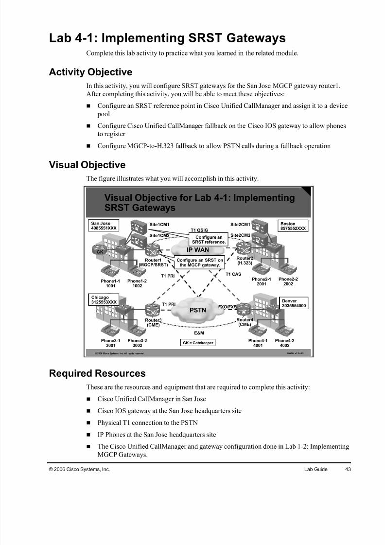
Lab 4-1: Implementing SRST GatewaysComplete this lab activity to practice what you learned in the related module.
Activity Objective
In this activity, you will configure SRST gateways for the San Jose MGCP gateway router1.
After completing this activity, you will be able to meet these objectives: Configure an SRST reference point in Cisco Unified CallManager and assign it to a device
pool
Configure Cisco Unified CallManager fallback on the Cisco IOS gateway to allow phones
to register
Configure MGCP-to-H.323 fallback to allow PSTN calls during a fallback operation
Visual Objective
The figure illustrates what you will accomplish in this activity.
© 2006 Cisco Systems, Inc. All rights reserved. GWGK v2.0—15
Phone2-12001
Phone2-22002
Router2(H.323)
Phone4-14001
Phone4-24002
Boston8575552XXX
Denver 3035554000
IP WAN
PSTNT1 PRI
T1 PRI T1 CAS
T1 QSIG
FXO/FXS
Phone1-1
1001
Phone1-2
1002
Router1(MGCP/SRST)
Site1CM1
Phone3-13001
Phone3-23002
San Jose4085551XXX
Chicago3125553XXX
GK
E&M
Site2CM1
Site2CM2
Visual Objective for Lab 4-1: ImplementingSRST Gateways
Configure an SRST onthe MGCP gateway.
Configure anSRST reference.
Site1CM2
Router4(CME)
Router3(CME)
GK = Gatekeeper
Required Resources
These are the resources and equipment that are required to complete this activity:
Cisco Unified CallManager in San Jose
Cisco IOS gateway at the San Jose headquarters site
Physical T1 connection to the PSTN
IP Phones at the San Jose headquarters site
The Cisco Unified CallManager and gateway configuration done in Lab 1-2: Implementing
MGCP Gateways.

7/27/2019 Gwgk20lg - Gk Rc Modified
http://slidepdf.com/reader/full/gwgk20lg-gk-rc-modified 44/107
44 Implementing Cisco Voice Gateways and Gatekeepers (GWGK) v2.0 © 2006 Cisco Systems, Inc.
Command List
The table describes the commands that are used in this activity.
SRST Configuration Commands
Command Description
call-manager-fallback Enters SRST configuration mode
ip source-address ip-address
Enables the router to receive messages from Cisco IPphones through the specified IP addresses
max-dn value [dual-line][preference preference-order ]
Sets the maximum number of DNs or virtual voice portsthat are supported by the router and activates the dual-linemode
max-ephones value Configures the maximum number of Cisco IP phones thatare supported by the router
max-conferences value Sets the maximum number of simultaneous three-partyconferences in SRST mode
ccm-manager fallback-mgcp Activates MGCP fallback
show call-manager-fallbackall
Displays the status of the Cisco SRST feature
show ephone Displays the Cisco IP phones that are registered to theCisco SRST router
debug ephone register Debug registration information of Cisco IP phonesregistered to the Cisco SRST router
Job Aids
These job aids are available to help you complete the lab activity.
Cisco IOS Voice Configuration Library
Cisco Unified CallManager help pages
Task 1: Configure the SRST Reference Point
In this task, you will define the San Jose MGCP gateway router1, configured in Lab1-1 of the
course, as SRST reference point in the San Jose Cisco Unified CallManager cluster.
Activity Procedure
Complete these steps:
Step 1 Access the Cisco Unified CallManager Administration page of the Cisco Unified
CallManager in San Jose and configure the Cisco IOS voice gateway in San Jose to
be used as an SRST reference.
Step 2 Assign the new SRST reference the device pool Default.

7/27/2019 Gwgk20lg - Gk Rc Modified
http://slidepdf.com/reader/full/gwgk20lg-gk-rc-modified 45/107
© 2006 Cisco Systems, Inc. Lab Guide 45
Activity Verification
You have completed this task when you attain these results:
On the San Jose IP phones, go to Settings > Device Configuration and verify that the IP
address of the MGCP-controlled gateway in San Jose is being displayed as CallManager 3
SRST.
Task 2: Configure CallManager FallbackIn this task, you will configure Cisco Unified CallManager fallback on the Cisco IOS gateway
in San Jose to allow phones to register.
Activity Procedure
Complete this step:
Step 1 On the San Jose MGCP gateway router1, configure SRST with these parameters:
Maximum number of phones: 24
Maximum number of lines: 48
Allow multiple calls per line
Dial plan pattern: 4085551…, four digit extensions
Source address: Fa0/0.P16 IP address
Activity Verification
You have completed this task when you attain these results:
Issuing the show call-manager-fallback all command on the Cisco IOS router in San Jose
will display the previously configured source IP address, ephone, and directory number
settings.
Task 3: Configure MGCP Fallback
In this task, you will configure MGCP-to-H.323 fallback to allow PSTN calls during a fallback
operation. That includes all tasks to allow MGCP fallback as well as the necessary dial peers in
order to allow PSTN routing during a Cisco Unified CallManager outage.
Activity Procedure
Complete these steps:
Step 1 Configure a new POTS dial peer using these credentials:
Destination pattern: 9T Destination: T1 PRI PSTN trunk
DID
Step 2 Enable MGCP fallback in case the Cisco Unified CallManager is not available.

7/27/2019 Gwgk20lg - Gk Rc Modified
http://slidepdf.com/reader/full/gwgk20lg-gk-rc-modified 46/107
46 Implementing Cisco Voice Gateways and Gatekeepers (GWGK) v2.0 © 2006 Cisco Systems, Inc.
Activity Verification
You have completed this task when you attain these results:
On Cisco Unified CallManager in San Jose, go to the Cisco Unified CallManager
serviceability and stop the Cisco Unified CallManager service.
Verify that the IP phones in San Jose reregister to the SRST router. The display of the IP
phones should show a system message indicating that SRST is active.
Make sure that calls can be placed from and to the PSTN by using the San Jose IP phones.

7/27/2019 Gwgk20lg - Gk Rc Modified
http://slidepdf.com/reader/full/gwgk20lg-gk-rc-modified 47/107
© 2006 Cisco Systems, Inc. Lab Guide 47
Lab 4-2: Implementing Media Resources UsingCisco IOS Gateway DSPs
Complete this lab activity to practice what you learned in the related module.
Activity Objective
In this activity, you will configure media resources for Cisco Unified CallManager on the Cisco
IOS gateway in San Jose. After completing this activity, you will be able to meet these
objectives:
Configure transcoding and conferencing functionality on a Cisco IOS gateway
Add the media resources to Cisco Unified CallManager
Visual Objective
The figure illustrates what you will accomplish in this activity.
© 2006 Cisco Systems, Inc. All rights reserved. GWGK v2.0—16
Visual Objective for Lab 4-2: Implementing MediaResources Using Cisco IOS Gateway DSPs
Phone2-12001
Phone2-22002
Router2(H.323)
Phone4-14001
Phone4-24002
Boston8575552XXX
Denver 3035554000
IP WAN
PSTNT1 PRI
T1 PRI T1 CAS
T1 QSIG
FXO/FXS
Phone1-11001
Phone1-21002
Router1(MGCP/SRST)
Site1CM1
Phone3-13001
Phone3-23002
San Jose4085551XXX
Chicago3125553XXX
GK
E&M
Site1CM2
Site2CM1
Site2CM2
Router4(CME)
Router3(CME)
GK = Gatekeeper
Required Resources
These are the resources and equipment that are required to complete this activity:
Cisco Unified CallManagers in San Jose and Boston
IP phones in San Jose and Boston
Cisco IOS gateway in San Jose

7/27/2019 Gwgk20lg - Gk Rc Modified
http://slidepdf.com/reader/full/gwgk20lg-gk-rc-modified 48/107
48 Implementing Cisco Voice Gateways and Gatekeepers (GWGK) v2.0 © 2006 Cisco Systems, Inc.
Command List
The table describes the commands that are used in this activity.
DSP Commands
Command Description
sccp ccm {ip-address |dns} identifieridentifier-number [port port-number ] [versionversion-number ]
Defines a Cisco Unified CallManager entity that can bereferenced by the identifier
sccp local local-interface Defines the local interface used for SCCP
sccp Starts the SCCP process
sccp ccm group group-number
Creates a SCCP Cisco Unified CallManager group
associate ccm identifier-number priority priority
Assigns a Cisco Unified CallManager entity to the group,including a priority (1=high, 4=low)
associate profile profile-identifier registerdevice-name
Assigns a DSP farm profile to the SCCP Cisco UnifiedCallManager group, and defines the device name that willbe configured in Cisco Unified CallManager
bind interface interface-type interface-number
Binds the SCCP group to a specific interface
voice-card slot Enters the voice-card configuration mode
dsp services dspfarm Enables DSP farm services
dspfarm profile profile-identifier {conference | mtp | transcode}
Creates a DSP farm profile for conferencing, MTP, or transcoding
codec codec-type Specifies the allowed codecs
maximum sessions number Defines the maximum number of sessions
associate application SCCP Enables SCCP for the profile
Job Aids
These job aids are available to help you complete the lab activity:
Cisco IOS Voice Configuration Library.
Cisco Unified CallManager help pages

7/27/2019 Gwgk20lg - Gk Rc Modified
http://slidepdf.com/reader/full/gwgk20lg-gk-rc-modified 49/107
© 2006 Cisco Systems, Inc. Lab Guide 49
Task 1: Configure Transcoding and Conferencing Resourceson Cisco IOS Gateways
In this task, you will configure SCCP providers for conferencing and transcoding on the Cisco
IOS voice gateway in San Jose.
Activity Procedure
Complete these steps:
Step 1 Log on to the Cisco IOS gateway in San Jose and enable the SCCP process. Verify
that the SCCP process is up and running.
Step 2 Configure the DSP farm on the gateway.
Step 3 Configure a transcoding DSP farm profile using these parameters:
All G.711 and G.729 codecs
Up to two sessions
Step 4 Configure a conferencing DSP farm profile using these parameters:
All G.711 and G.729 codecs
Up to one session
Step 5 Configure the FastEthernet interface 0/0 of the gateway to be used as the SCCP
interface.
Step 6 Configure the Cisco Unified CallManager in San Jose to be used as the SCCP entity.
Step 7 Configure a new SCCP Cisco Unified CallManager group that contains the new
transcoding and conferencing DSP farms. Use these identifiers for registration:
Transcoding: XCODERrouter1
Conferencing: CFBrouter1
Activity Verification
You have completed this task when you attain these results:
Use the show sccp command to verify the configuration. The SCCP process must be up
and running, and the Cisco Unified CallManager in San Jose must be used as the preferred
Cisco Unified CallManager.

7/27/2019 Gwgk20lg - Gk Rc Modified
http://slidepdf.com/reader/full/gwgk20lg-gk-rc-modified 50/107
50 Implementing Cisco Voice Gateways and Gatekeepers (GWGK) v2.0 © 2006 Cisco Systems, Inc.
Task 2: Configure Media Resources in Cisco UnifiedCallManager
In this task, you will add Cisco IOS media resources to the Cisco Unified CallManager in San
Jose and use them for software and hardware conferences.
Activity Procedure
Complete these steps:
Step 1 Log on to the Cisco Unified CallManager in Boston and change the codec for the
default region to G.729.
Step 2 Log on to the Cisco Unified CallManager in San Jose and add the transcoding
device configured in Task 1: Configure Transcoding and Conferencing Resources on
Cisco IOS Gateways as the transcoder.
Step 3 Make sure that the Cisco Unified CallManager transcoder is up and running on the
system.
Step 4 Add the conferencing device configured in Task 1: Configure Transcoding and
Conferencing Resources on Cisco IOS Gateways as IOS-based Conference Bridge.
Step 5 Make sure that the Cisco Unified CallManager software conference bridge is up and
running on the system.
Step 6 Create a new media resource group named SJC-SWConf and add the Cisco Unified
CallManager software conference bridge and the transcoder XCODERroutrer1 to it.
Step 7 Create another new media resource group named SJC-HWConf and add the
hardware conference bridge CFBrouter1 to it.
Step 8 Create a new media resource group list named SJC-MRGL and add the media
resource group SJC-SWConf to it.
Step 9 Assign the new media resource group list to the device pool default.
Step 10 Add ICT’s and modify the dial plan at San Jose and Boston to route calls between
these sites via ICT instead of the QSIG connection.
Step 11 After verifying the correct operation of the media resources, change the media
resource group used in the media resource group list SJC-MRGL to SJC-HWConf.
Activity Verification
You have completed this task when you attain these results:
To verify proper operation of the transcoders, ensure that the media resource group SJC-SWConf is used and initiate a conference between the two phones in San Jose and one of
the Boston phones via the IP network. The transcoder on the Cisco IOS gateway in San
Jose should transcode the G.729 audio stream from Boston and allow conferencing using
the G.711-only software conference bridge on the Cisco Unified CallManager.
To verify proper operation of the hardware conference bridge, ensure that the media
resource group SJC-HWConf is used and initiate a conference between the two phones in
San Jose and one of the Boston phones via the IP network. The hardware conference
between San Jose G.711 and Boston G.729 should work without an extra transcoder.

7/27/2019 Gwgk20lg - Gk Rc Modified
http://slidepdf.com/reader/full/gwgk20lg-gk-rc-modified 51/107
© 2006 Cisco Systems, Inc. Lab Guide 51
Lab 4-3: Implementing Call Applications on CiscoIOS Gateways
Complete this lab activity to practice what you learned in the related module.
Activity Objective
In this activity, you will implement an Auto Attendant call application on a Cisco IOS gateway.
After completing this activity, you will be able to meet this objective:
Configure the sample Auto Attendant call application to handle inbound PSTN calls
Visual Objective
The figure illustrates what you will accomplish in this activity.
© 2006 Cisco Systems, Inc. All rights reserved. GWGK v2.0—17
Phone2-12001
Phone2-22002
Router2(H.323)
Phone4-14001
Phone4-24002
Boston8575552XXX
Denver 3035554000
IP WAN
PSTN
T1 PRI
T1 PRI T1 CAS
T1 QSIG
FXO/FXS
Phone1-11001
Phone1-21002
Router1(MGCP/SRST)
Site1CM1
Phone3-13001
Phone3-23002
San Jose4085551XXX
Chicago3125553XXX
GK
E&M
Site1CM2
Site2CM1
Site2CM2
Visual Objective for Lab 4-3: ImplementingCall Applications on Cisco IOS Gateways
Implement an AutoAttendant script.
Router4(CME)
Router3(CME)
GK = Gatekeeper
Required Resources
These are the resources and equipment that are required to complete this activity:
Cisco IOS gateway router4 in Denver with configured inbound PSTN routing
Phones in Denver
PSTN phone

7/27/2019 Gwgk20lg - Gk Rc Modified
http://slidepdf.com/reader/full/gwgk20lg-gk-rc-modified 52/107
52 Implementing Cisco Voice Gateways and Gatekeepers (GWGK) v2.0 © 2006 Cisco Systems, Inc.
Command List
The tables describe the commands that are used in this activity.
Service Definition Commands
Command Description
application To enter the application configuration mode, use the globalapplication command.
service service-nameservice-location
To define a new application and enter the service configurationmode, use the service command. Specify a meaningful nameusing the service-name option, and the location of the Tcl scriptusing the service-location option.
Parameter Definition Commands
Command Description
param parameter value To specify a parameter for a defined service, use the param command in service configuration mode. The parameter option
defines the parameter. and the value option assigns a value to it.
paramspace language {locationlocation|languagelanguage|index index }
Some parameters are grouped together using the paramspace command. One example is the paramspace language command,which specifies language settings for an application.
Service Association Commands
Command Description
service service-name[out-bound]
To associate a call application with an inbound dial peer, use theservice command in dial-peer configuration mode. If theapplication should be used for outbound dial peers, use the out-
bound option.
Applications handling inbound calls should be associated withPOTS dial peers, whereas applications handling outbound callsshould be bound to VoIP dial peers.
Job Aids
This job aid is available to help you complete the lab activity:
Voice configuration library on Cisco.com

7/27/2019 Gwgk20lg - Gk Rc Modified
http://slidepdf.com/reader/full/gwgk20lg-gk-rc-modified 53/107

7/27/2019 Gwgk20lg - Gk Rc Modified
http://slidepdf.com/reader/full/gwgk20lg-gk-rc-modified 54/107
54 Implementing Cisco Voice Gateways and Gatekeepers (GWGK) v2.0 © 2006 Cisco Systems, Inc.
Task 2: Associate the Auto Attendant Application with a DialPeer
Activity Procedure
Complete these steps:
Step 1 On the Denver Cisco Unified CallManager Express router4, remove any existing
connection plar statement from voice port 0/0/0.
Step 2 Associate the inbound Auto Attendant application with dial peer 9.
Activity Verification
You have completed this task when you attain these results:
PSTN calls to 3035554000 are answered by the Auto Attendant.
Phone 3-1 and phone 3-2 are reachable via the Auto Attendant.
If 0 is dialed when connected with the Auto Attendant, the call is forwarded to phone 3-2.

7/27/2019 Gwgk20lg - Gk Rc Modified
http://slidepdf.com/reader/full/gwgk20lg-gk-rc-modified 55/107
© 2006 Cisco Systems, Inc. Lab Guide 55
Lab 5-1: Implementing Basic Gatekeeper Functionality
Complete this lab activity to practice what you learned in the related module.
Activity Objective
In this activity, you will configure the San Jose gatekeeper GK as a gatekeeper controlling two
zones: SJC and CHI. Call routing between San Jose and Chicago will be done via the
gatekeeper. After completing this activity, you will be able to meet these objectives:
Configure an H.323 gatekeeper at San Jose to support multiple local zones
Register Cisco Unified CallManager and gateways at the gatekeeper
Test the gatekeeper configuration, the Cisco Unified CallManager, and gateway registration
Visual Objective
The figure illustrates what you will accomplish in this activity.
© 2006 Cisco Systems, Inc. All rights reserved. GWGK v2.0—18
Phone2-12001 Phone2-22002
Router2(H.323)
Phone4-14001
Phone4-24002
Boston8575552XXX
Denver 3035554000
IP WAN
PSTNT1 PRI
T1 PRI T1 CAS
T1 QSIG
FXO/FXS
Phone1-11001
Phone1-21002
Router1(MGCP/SRST)
Site1CM1
Phone3-13001
Phone3-23002
San Jose4085551XXX
Chicago3125553XXX
GK
E&M
Site1CM2
Site2CM1
Site2CM2
Visual Objective for Lab 5-1: ImplementingBasic Gatekeeper Functionality
Register the CiscoUnified CallManagersat the gatekeeper in
San Jose.
Configure agatekeeper withtwo local zones:
SJC and CHI.
Router4(CME)
Router3(CME)
Register the gatewayat the gatekeeper in
San Jose.
GK = Gatekeeper

7/27/2019 Gwgk20lg - Gk Rc Modified
http://slidepdf.com/reader/full/gwgk20lg-gk-rc-modified 56/107
56 Implementing Cisco Voice Gateways and Gatekeepers (GWGK) v2.0 © 2006 Cisco Systems, Inc.
Required Resources
These are the resources and equipment that are required to complete this activity:
San Jose Cisco Unified CallManager cluster
Chicago Cisco Unified CallManager Express router3
San Jose gatekeeper GK
San Jose IP phones
Chicago IP phones
Command List
The tables describe the commands that are used in this activity.
Gatekeeper Configuration Commands
Command Description
gatekeeperTo enter gatekeeper configuration mode, use thegatekeeper command in global configuration mode.
zone local zone-namedomain-name [ras-IP-address]
Specifies a zone controlled by a gatekeeper with thesearguments:
gatekeeper-name: Specifies the gatekeeper name or zone name. This is usually the fully domain-qualifiedhost name of the gatekeeper. For example, if thedomain name is cisco.com, the gatekeeper namemight be gk1.cisco.com. However, if the gatekeeper iscontrolling multiple zones, the gatekeeper name for each zone should be some unique string that has amnemonic value.
domain-name: Specifies the domain name served by
this gatekeeper. ras-IP-address: (Optional) Specifies the IP address of
one of the interfaces on the gatekeeper. When thegatekeeper responds to gatekeeper discoverymessages, it signals the endpoint or gateway to usethis address in future communications.
Note: Setting this address for one local zone makes it theaddress used for all local zones.
no shutdown Brings the gatekeeper online.

7/27/2019 Gwgk20lg - Gk Rc Modified
http://slidepdf.com/reader/full/gwgk20lg-gk-rc-modified 57/107
© 2006 Cisco Systems, Inc. Lab Guide 57
Router(config-gk)# zone prefix gatekeeper-name e164-prefix [ blast | seq ][gw-priority priority gw-alias [gw-alias, ...]]
Adds a prefix to the gatekeeper zone list with thesekeywords and arguments:
gatekeeper-name: Specifies the name of a local or remote gatekeeper, which must have been defined byusing the zone local or zone remote command.
e164-prefix : Specifies an E.164 prefix in standard formfollowed by dots (.). Each dot represents a number inthe E.164 address. For example, 212....... is matchedby 212 and any 7 numbers.
Note: Although the preferred configuration method is touse a dot to represent each digit in an E.164 address, youcan also enter an asterisk (*) to match any number of digits.
blast: (Optional) If you list multiple hopoffs, thisindicates that the LRQs should be sent simultaneouslyto the gatekeepers based on the order in which theywere listed. The default is seq.
seq: (Optional) If you list multiple hopoffs, thisindicates that the LRQs should be sent sequentially tothe gatekeepers based on the order in which theywere listed. The default is seq.
gw-priority priority gw-alias: (Optional) Use the gw-priority option to define how the gatekeeper selectsgateways in its local zone for calls to numbers thatbegin with e164-prefix . Do not use this option to setpriority levels for a prefix assigned to a remotegatekeeper.
Use values from 0 to 10. A 0 value prevents thegatekeeper from using the gateway gw-alias for that prefix.Value 10 places the highest priority on gateway gw-alias. If you do not specify a priority value for a gateway, the value5 is assigned.
To assign the same priority value for one prefix to multiplegateways, list all the gateway names after the pri-0-to-10 value.
The gw-alias name is the H.323 ID of a gateway that isregistered or will register with the gatekeeper. This name isset on the gateway with the h323-gateway voip h.323-idcommand.
Router(config-gk)# gw-type-prefix type-prefix [hopoff gkid1] [hopoffgkid2] [hopoff gkidn] [seq | blast] [default-technology] [gw ipaddripaddr [ port]]
Adds a technology prefix to the gatekeeper configurationlist with these keywords and arguments:
type-prefix : A technology prefix is recognized and isstripped before checking for the zone prefix. It isstrongly recommended that you select technologyprefixes that do not lead to ambiguity with zoneprefixes. Do this by using the # character to terminatetechnology prefixes, such as 3#..
hopoff gkid : (Optional) Use this option to specify thegatekeeper where the call is to hop off, regardless of the zone prefix in the destination address. The gkid argument refers to a gatekeeper previously configuredusing the zone local or zone remote comment. Youcan enter this keyword and argument multiple times toconfigure redundant gatekeepers for a giventechnology prefix.
blast: (Optional) If you list multiple hopoffs, thisindicates that the location requests (LRQs) should besent simultaneously to the gatekeepers based on the

7/27/2019 Gwgk20lg - Gk Rc Modified
http://slidepdf.com/reader/full/gwgk20lg-gk-rc-modified 58/107
58 Implementing Cisco Voice Gateways and Gatekeepers (GWGK) v2.0 © 2006 Cisco Systems, Inc.
order in which they were listed. The default is seq.
seq: (Optional) If you list multiple hopoffs, thisindicates that the LRQs should be sent sequentially tothe gatekeepers based on the order in which theywere listed. The default is seq.
default-technology : (Optional) Gateways registeringwith this prefix option are used as the default for routing any addresses that are otherwise unresolved.
gw ipaddr ipaddr [ port ]: (Optional) Use this option to
indicate that the gateway is incapable of registeringtechnology prefixes. When it registers, it adds thegateway to the group for this type prefix, just as if ithad sent the technology prefix in its registration. Thisparameter can be repeated to associate more thanone gateway with a technology prefix.
show gatekeeper calls To display the status of each ongoing call of which agatekeeper is aware, use the show gatekeeper callscommand in privileged EXEC mode.
show gatekeeper status To display the overall gatekeeper status, including theauthorization and authentication status and zone status,use the show gatekeeper status command in EXECmode.
show gatekeeper endpoints To display the status of all registered endpoints for agatekeeper, use the show gatekeeper endpoints command in privileged EXEC mode.
show gatekeeper gw-type- prefix
To display the gateway technology prefix table, use theshow gatekeeper gw-type-prefix command in privilegedEXEC mode.
show gatekeeper zone prefix [all]
To display the zone prefix table, use the show gatekeeper zone prefix command in privileged EXEC mode.
show gatekeeper zonestatus
To display the status of zones related to a gatekeeper, usethe show gatekeeper zone status command in privilegedEXEC mode.
Gateway Configuration Commands
Command Description
gateway
Example:
Router(config)# gateway
Enters gateway configuration mode and enables thegateway to register with the gatekeeper.
h323-gateway voipinterface
Identifies this as a VoIP gateway interface.
h323-gateway voip id gatekeeper-id {ipaddr ip-
address [port]| multicast}[priority priority ]
(Optional) Defines the name and location of the gatekeeper for this gateway with these keywords and arguments:
gatekeeper-id : H.323 identification of the gatekeeper.Must exactly match the gatekeeper ID in thegatekeeper configuration. Recommended format:name.domainname.
ipaddr ip-address: IP address to be used to identifythe gatekeeper.
port : Port number used.
multicast: Gateway uses multicast to locate thegatekeeper.

7/27/2019 Gwgk20lg - Gk Rc Modified
http://slidepdf.com/reader/full/gwgk20lg-gk-rc-modified 59/107
© 2006 Cisco Systems, Inc. Lab Guide 59
priority priority : Priority of this gatekeeper. Theacceptable range is 1 to 127, and the default is 127.
h323-gateway voip h323-id interface-id
(Optional) Defines the H.323 name of the gateway,identifying this gateway to its associated gatekeeper.
Usually this ID is the name of the gateway, with thegatekeeper domain name appended to the end like this:name@domainname.
h323-gateway voip tech-
prefix prefix
(Optional) Defines the numbers used as the technology
prefix that the gateway registers with the gatekeeper.
This command can contain up to 11 characters. Although itis not strictly necessary, a pound symbol (#) is frequentlyused as the last digit in a prefix. Valid characters are 0 to 9,#, and *.
session target ras RAS signaling function protocol is being used, meaningthat a gatekeeper is consulted to translate the E.164address into an IP address.
Job Aids
There are no job aids for this activity.
Task 1: Configure Local Zones at the San Jose Gatekeeper
Configure two local zones, SanJose and Chicago, on the San Jose site gatekeeper. Configure
appropriate dial-plan information for the gatekeeper to resolve calls between sites SanJose and
Chicago.
Activity Procedure
Complete these steps:
Step 1 On the San Jose gatekeeper GK, configure a gatekeeper using these parameters:
Local zone SJC, domain cisco.com, IP address of the LAN interface Local zone CHI, domain cisco.com, IP address of the LAN interface
Step 2 Enable the gatekeeper process on GK.
Activity Verification
You have completed this task when you attain these results:
The GK gatekeeper is up and running with two local zones: SanJose and Chicago.

7/27/2019 Gwgk20lg - Gk Rc Modified
http://slidepdf.com/reader/full/gwgk20lg-gk-rc-modified 60/107
60 Implementing Cisco Voice Gateways and Gatekeepers (GWGK) v2.0 © 2006 Cisco Systems, Inc.
Task 2: Configure Technology and Zone Prefixes
In this task, you will configure technology prefixes and interzone routing on the San Jose
gatekeeper. Call routing will use the site extension range. For example, any call starting with 1
should be routed to the SJC zone, and any call starting with 3 should be routed to the CHI zone.
Activity Procedure
Complete these steps:
Step 1 On the San Jose gatekeeper GK, configure the zone prefix for the SJC zone. Any
call to a San Jose extension starting with 1 should be routed to this zone.
Step 2 Configure the zone prefix for the CHI zone. Any call to a Chicago extension starting
with 3 should be routed to this zone.
Step 3 Configure a default gateway technology prefix of 1#.
Activity Verification
You have completed this task when you attain these results:
The zone prefixes for the SJC and CHI zones are configured correctly
The default technology prefix is 1#.
Task 3: Register Cisco Unified CallManager at the Gatekeeper
In this task, you will register the San Jose Cisco Unified CallManager cluster with the San Jose
gatekeeper. The San Jose Cisco Unified CallManager cluster should register with the SJC zone
and a technology prefix of 1#.
Activity Procedure
Complete these steps:
Step 1 On the San Jose Cisco Unified CallManager cluster, add a new gatekeeper. Use the
LAN IP address of the San Jose gatekeeper GK.
Step 2 Create a new gatekeeper-controlled intercluster trunk. Use the previously configure
gatekeeper and ensure that the trunk is registered in zone SJC and with the
technology prefix 1#.
Step 3 Change the existing route pattern 3XXX, which points directly to the Chicago Cisco
Unified CallManager Express router3, to point to the new gatekeeper-controlled
intercluster trunk.
Step 4 Remove the old non-gatekeeper-controlled ICT pointing to the Chicago CiscoUnified CallManager Express router3.
Step 5 On the San Jose gatekeeper GK, verify that the San Jose Cisco Unified CallManager
cluster has registered.
Step 6 Reconfigure the gatekeeper zone prefixes to send calls first to Site1CM1, and then to
Site1CM2.
7/27/2019 Gwgk20lg - Gk Rc Modified
http://slidepdf.com/reader/full/gwgk20lg-gk-rc-modified 61/107
© 2006 Cisco Systems, Inc. Lab Guide 61
Activity Verification
You have completed this task when you attain these results:
The San Jose Cisco Unified CallManager cluster is registered with the zone SJC and
technology prefix 1#.
The gatekeeper is configured with Site1CM1 having higher priority than Site1CM2 for
calls sent to IP phones in San Jose.
Task 4: Register Gateways at the Gatekeeper Configure the gateway in Chicago in order to register it with the gatekeeper in San Jose.
Activity Procedure
Complete these steps:
Step 1 On the Chicago Cisco Unified CallManager Express router3, configure the H.323
gateway process. The gateway should register with zone CHI and technology prefix
1#. Use the LAN interface as the H.323 source interface and ensure that you
configure a proper H.323 gateway ID.
Step 2 Reconfigure the existing VoIP dial peers that point to San Jose. Instead of routing
directly to the San Jose Cisco Unified CallManager cluster, the call should be routed
to the San Jose gatekeeper GK. Remove the redundant second VoIP dial peer.
Step 3 Ensure that the Chicago Cisco Unified CallManager Express router3 does not
register any ephone-dn with the gatekeeper.
Activity Verification
You have completed this task when you attain these results:
The gateway is registered at the gatekeeper with a technology prefix of 1#.
Calls between the San Jose Cisco Unified CallManager cluster and the Chicago CiscoUnified CallManager Express router3 are possible via the gatekeeper.

7/27/2019 Gwgk20lg - Gk Rc Modified
http://slidepdf.com/reader/full/gwgk20lg-gk-rc-modified 62/107
62 Implementing Cisco Voice Gateways and Gatekeepers (GWGK) v2.0 © 2006 Cisco Systems, Inc.
Lab 5-2: Implementing Gatekeeper-Based CACComplete this lab activity to practice what you learned in the related module.
Activity Objective
In this activity, you will configure the San Jose gatekeeper to use CAC between the zones SJC
and CHI. After completing this activity, you will be able to meet these objectives: Calculate bandwidth requirements for gatekeeper CAC
Configure and test gatekeeper bandwidth configuration
Configure RAI so that gatekeeper and gateways communicate with each other
Visual Objective
The figure illustrates what you will accomplish in this activity.
© 2006 Cisco Systems, Inc. All rights reserved. GWGK v2.0—19
Phone2-12001
Phone2-22002
Router2(H.323)
Phone4-14001
Phone4-24002
Boston8575552XXX
Denver 3035554000
IP WAN
PSTNT1 PRI
T1 PRI T1 CAS
T1 QSIG
FXO/FXS
Phone1-11001
Phone1-21002
Router1(MGCP/SRST)
Site1CM1
Phone3-13001
Phone3-23002
San Jose4085551XXX
Chicago
3125553XXX
GK
E&M
Site1CM2
Site2CM1
Site2CM2
Visual Objective for Lab 5-2: Implementing
Gatekeeper-Based CAC
Configure CAC onthe gatekeeper.
Router4(CME)
Router3(CME)
GK = Gatekeeper
Required Resources
These are the resources and equipment that are required to complete this activity:
San Jose Cisco Unified CallManager cluster
San Jose gatekeeper GK set up for call routing between San Jose and Chicago
Chicago Cisco Unified CallManager Express router3
San Jose IP phones
Chicago IP phones

7/27/2019 Gwgk20lg - Gk Rc Modified
http://slidepdf.com/reader/full/gwgk20lg-gk-rc-modified 63/107
© 2006 Cisco Systems, Inc. Lab Guide 63
Command List
The tables describe the commands that are used in this activity.
Gatekeeper Configuration Commands
Command Description
bandwidth {interzone |total | session} {default| zone zone-name}bandwidth-size
To specify the maximum aggregate bandwidth for H.323traffic and verify the available bandwidth of the destinationgatekeeper, use the bandwidth command in gatekeeper configuration mode. To disable maximum aggregatebandwidth, use the no form of this command.
These are the keywords and arguments for this command:
interzone: Total amount of bandwidth for H.323 trafficfrom the zone to any other zone
total: Total amount of bandwidth for H.323 trafficallowed in the zone
session: Maximum bandwidth allowed for a session inthe zone
default: Default value for all zones
zone: A particular zone
zone-name: Name of the particular zone
bandwidth-size: Maximum bandwidth, in kbps
For interzone and total, the range is from 1 to 10,000,000.For session, the range is from 1 to 5000.
show gatekeeper calls To display the status of each ongoing call of which agatekeeper is aware, use the show gatekeeper callscommand in privileged EXEC mode.
show gatekeeper status To display the overall gatekeeper status, including the
authorization and authentication status and zone status,use the show gatekeeper status command in EXECmode.
show gatekeeper endpoints To display the status of all registered endpoints for agatekeeper, use the show gatekeeper endpoints command in privileged EXEC mode.
show gatekeeper gw-type- prefix
To display the gateway technology prefix table, use theshow gatekeeper gw-type-prefix command in privilegedEXEC mode.
show gatekeeper zone prefix [all]
To display the zone prefix table, use the show gatekeeper zone prefix command in privileged EXEC mode.
show gatekeeper zonestatusTo display the status of zones related to a gatekeeper, usethe show gatekeeper zone status command in privilegedEXEC mode.

7/27/2019 Gwgk20lg - Gk Rc Modified
http://slidepdf.com/reader/full/gwgk20lg-gk-rc-modified 64/107
64 Implementing Cisco Voice Gateways and Gatekeepers (GWGK) v2.0 © 2006 Cisco Systems, Inc.
Gateway Configuration Commands
Command Description
resource threshold [all][high percentage-value][low percentage-value]
To configure a gateway to report H.323 resourceavailability to its gatekeeper, use the resource thresholdcommand in gateway configuration mode. To disablegateway resource-level reporting, use the no form of thiscommand.
These are the keywords and arguments for this command:
all: (Optional) High- and low-parameter settings areapplied to all monitored H.323 resources. This is thedefault condition.
high percentage-value: (Optional) Resource utilizationlevel that triggers a RAI message that indicates thatH.323 resource use is high. Enter a number between 1and 100 that represents the high-resource utilizationpercentage. A value of 100 specifies high-resourceusage when any H.323 resource is unavailable. Thedefault is 90 percent.
low percentage-value: (Optional) Resource utilizationlevel that triggers an RAI message that indicatesH.323 resource usage has dropped below the high-usage level. Enter a number between 1 and 100 thatrepresents the acceptable resource utilizationpercentage. After the gateway sends a high-utilizationmessage, it waits to send the resource recoverymessage until the resource use drops below the valuedefined by the low parameter. The default is 90percent.
show call resource voicethreshold
To display the threshold configuration settings and statusfor an H.323 gateway, use the show call resource voicethreshold command in privileged EXEC mode
Job Aids
There are no job aids for this activity.
Task 1: Calculate Bandwidth Requirements
Calculate the bandwidth requirements for 1 x G.711 from the San Jose site to the Chicago site.
Activity Procedure
Complete this step:
Step 1 Calculate the bandwidth for the 1 x G.711 call.
Activity VerificationYou have completed this task when you attain these results:
You have calculated the correct bandwidth for 1 x G.711 call in a H.323 gatekeeper
network.

7/27/2019 Gwgk20lg - Gk Rc Modified
http://slidepdf.com/reader/full/gwgk20lg-gk-rc-modified 65/107
© 2006 Cisco Systems, Inc. Lab Guide 65
Task 2: Configure Zone Bandwidth
Configure the correct zone bandwidth for calls from the San Jose zone to the Chicago zone.
Activity Procedure
Complete this step:
Step 1 On the San Jose gatekeeper GK, configure the interzone bandwidth for one G.711
call for the SJC zone and the CHI zone.
Activity Verification
You have completed this task when you attain these results:
The correct bandwidth is configured on the gatekeeper. Create a call from any phone in San
Jose to a phone in Chicago. Use the debug h225 asn1 and the show gatekeeper status
commands to verify correct bandwidth operation.
Place a second call between from Chicago to San Jose. The call should be rejected and
routed over the PSTN.

7/27/2019 Gwgk20lg - Gk Rc Modified
http://slidepdf.com/reader/full/gwgk20lg-gk-rc-modified 66/107
66 Implementing Cisco Voice Gateways and Gatekeepers (GWGK) v2.0 © 2006 Cisco Systems, Inc.
Lab 5-3: Configuring Remote ZonesComplete this lab activity to practice what you learned in the related module.
Activity Objective
In this activity, you will configure the Boston H.323 gateway router2 to also provide
gatekeeper functionality for Boston. The Boston Cisco Unified CallManager cluster willregister with the gatekeeper in Boston. Calls will then be routed between the two gatekeepers.
After completing this activity, you will be able to meet these objectives:
Configure remote zones on the gatekeeper
Configure remote zone prefixes that point to another gatekeeper in the network
Visual Objective
The figure illustrates what you will accomplish in this activity.
© 2006 Cisco Systems, Inc. All rights reserved. GWGK v2.0—20
Phone2-12001
Phone2-22002
Router2(H.323)
Phone4-14001
Phone4-24002
Boston8575552XXX
Denver 3035554000
IP WAN
PSTNT1 PRI
T1 PRI T1 CAS
T1 QSIG
FXO/FXS
Phone1-11001
Phone1-21002
Router1(MGCP/SRST)
Site1CM1
Phone3-13001
Phone3-23002
San Jose4085551XXX
Chicago3125553XXX
GK
E&M
Site1CM2
Site2CM1
Site2CM2
Visual Objective for Lab 5-3: ConfiguringRemote Zones
Register theCisco Unified
CallManager atthe gatekeeper
in Boston.
Configure agatekeeper with a
local BOS zone andSJC and CHI
remote zones.
Configure remotezone routing.
Configure remotezone routing.
Router4(CME)
Router3(CME)
GK = Gatekeeper
Required Resources
These are the resources and equipment that are required to complete this activity:
San Jose Cisco Unified CallManager cluster registered with the San Jose gatekeeper GK.
Chicago Cisco Unified CallManager Express router3 registered with the San Jose
gatekeeper GK
Boston H.323 gateway router2
Boston Cisco Unified CallManager cluster
San Jose IP phones
Chicago IP phones
Boston IP phones

7/27/2019 Gwgk20lg - Gk Rc Modified
http://slidepdf.com/reader/full/gwgk20lg-gk-rc-modified 67/107
© 2006 Cisco Systems, Inc. Lab Guide 67
Command List
The tables describe the commands that are used in this activity.
Gatekeeper Configuration Commands
Command Description
gatekeeper To enter gatekeeper configuration mode, use the
gatekeeper command in global configuration mode.
zone local zone-namedomain-name [ras-IP-address]
Specifies a zone controlled by a gatekeeper with thesearguments:
gatekeeper-name: Specifies the gatekeeper name or zone name. This is usually the fully domain-qualifiedhost name of the gatekeeper. For example, if thedomain name is cisco.com, the gatekeeper namemight be gk1.cisco.com. However, if the gatekeeper iscontrolling multiple zones, the gatekeeper name for each zone should be some unique string that has amnemonic value.
domain-name: Specifies the domain name served bythis gatekeeper.
ras-IP-address: (Optional) Specifies the IP address of one of the interfaces on the gatekeeper. When thegatekeeper responds to gatekeeper discoverymessages, it signals the endpoint or gateway to usethis address in future communications.
Note: Setting this address for one local zone makes it theaddress used for all local zones.
zone remote other-gatekeeper-name other-domain-name other-gatekeeper-ip-address[ port-number ] [cost cost-value [ priority priority-value]] [foreign-domain][invia inbound-gatekeeper ]| [outvia outbound-gatekeeper ]
Use the zone remote command in gatekeeper configuration mode to statically specify a remote zone if DNS is unavailable or undesirable. Use the no form of thiscommand to remove the remote zone.
no shutdown Brings the gatekeeper online.
Router(config-gk)# zone prefix gatekeeper-name e164-prefix [ blast | seq ][gw-priority priority gw-alias [gw-alias, ...]]
Adds a prefix to the gatekeeper zone list with thesekeywords and arguments:
gatekeeper-name: Specifies the name of a local or remote gatekeeper, which must have been defined byusing the zone local or zone remote command.
e164-prefix : Specifies an E.164 prefix in standard formfollowed by dots (.). Each dot represents a number inthe E.164 address. For example, 212....... is matchedby 212 and any 7 numbers.
Note: Although the preferred configuration method is touse a dot to represent each digit in an E.164 address, youcan also enter an asterisk (*) to match any number of digits.
blast: (Optional) If you list multiple hopoffs, thisindicates that the LRQs should be sent simultaneouslyto the gatekeepers based on the order in which theywere listed. The default is seq.
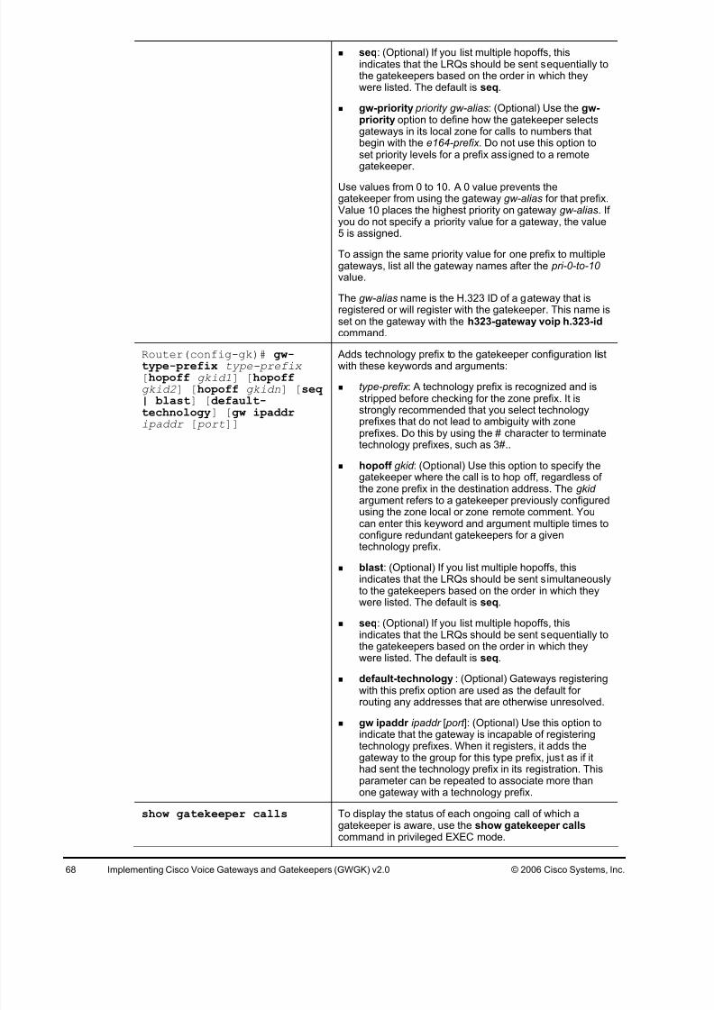
7/27/2019 Gwgk20lg - Gk Rc Modified
http://slidepdf.com/reader/full/gwgk20lg-gk-rc-modified 68/107
68 Implementing Cisco Voice Gateways and Gatekeepers (GWGK) v2.0 © 2006 Cisco Systems, Inc.
seq: (Optional) If you list multiple hopoffs, thisindicates that the LRQs should be sent sequentially tothe gatekeepers based on the order in which theywere listed. The default is seq.
gw-priority priority gw-alias: (Optional) Use the gw-priority option to define how the gatekeeper selectsgateways in its local zone for calls to numbers thatbegin with the e164-prefix. Do not use this option toset priority levels for a prefix assigned to a remotegatekeeper.
Use values from 0 to 10. A 0 value prevents thegatekeeper from using the gateway gw-alias for that prefix.Value 10 places the highest priority on gateway gw-alias. If you do not specify a priority value for a gateway, the value5 is assigned.
To assign the same priority value for one prefix to multiplegateways, list all the gateway names after the pri-0-to-10 value.
The gw-alias name is the H.323 ID of a gateway that isregistered or will register with the gatekeeper. This name isset on the gateway with the h323-gateway voip h.323-idcommand.
Router(config-gk)# gw-type-prefix type-prefix [hopoff gkid1] [hopoffgkid2] [hopoff gkidn] [seq | blast] [default-technology] [gw ipaddripaddr [ port]]
Adds technology prefix to the gatekeeper configuration listwith these keywords and arguments:
type-prefix : A technology prefix is recognized and isstripped before checking for the zone prefix. It isstrongly recommended that you select technologyprefixes that do not lead to ambiguity with zoneprefixes. Do this by using the # character to terminatetechnology prefixes, such as 3#..
hopoff gkid : (Optional) Use this option to specify thegatekeeper where the call is to hop off, regardless of the zone prefix in the destination address. The gkid argument refers to a gatekeeper previously configuredusing the zone local or zone remote comment. Youcan enter this keyword and argument multiple times toconfigure redundant gatekeepers for a giventechnology prefix.
blast: (Optional) If you list multiple hopoffs, thisindicates that the LRQs should be sent simultaneouslyto the gatekeepers based on the order in which theywere listed. The default is seq.
seq: (Optional) If you list multiple hopoffs, thisindicates that the LRQs should be sent sequentially tothe gatekeepers based on the order in which theywere listed. The default is seq.
default-technology : (Optional) Gateways registeringwith this prefix option are used as the default for routing any addresses that are otherwise unresolved.
gw ipaddr ipaddr [ port ]: (Optional) Use this option toindicate that the gateway is incapable of registeringtechnology prefixes. When it registers, it adds thegateway to the group for this type prefix, just as if ithad sent the technology prefix in its registration. Thisparameter can be repeated to associate more thanone gateway with a technology prefix.
show gatekeeper calls To display the status of each ongoing call of which agatekeeper is aware, use the show gatekeeper callscommand in privileged EXEC mode.

7/27/2019 Gwgk20lg - Gk Rc Modified
http://slidepdf.com/reader/full/gwgk20lg-gk-rc-modified 69/107
© 2006 Cisco Systems, Inc. Lab Guide 69
show gatekeeper status To display overall gatekeeper status, includingauthorization and authentication status and zone status,use the show gatekeeper status command in EXECmode.
show gatekeeper endpoints To display the status of all registered endpoints for agatekeeper, use the show gatekeeper endpoints command in privileged EXEC mode.
show gatekeeper gw-type- prefix
To display the gateway technology prefix table, use theshow gatekeeper gw-type-prefix command in privileged
EXEC mode.
show gatekeeper zone prefix [all]
To display the zone prefix table, use the show gatekeeper zone prefix command in privileged EXEC mode.
show gatekeeper zonestatus
To display the status of zones related to a gatekeeper, usethe show gatekeeper zone status command in privilegedEXEC mode.
Gateway Configuration Commands
Command Description
gateway Enters gateway configuration mode and enables the
gateway to register with the gatekeeper.
h323-gateway voipinterface
Identifies this as a VoIP gateway interface.
h323-gateway voip id gatekeeper-id {ipaddr ip-address [port]| multicast}[priority priority ]
Example:
Router(config-if)# h323-gateway voip id gk3.gg-dn1ipaddr 172.18.0.0 1719
(Optional) Defines the name and location of the gatekeeper for this gateway with these keywords and arguments:
gatekeeper-id : The H.323 identification of thegatekeeper. This must exactly match the gatekeeper ID in the gatekeeper configuration. The recommendedformat is name.domainname.
ipaddr ip-address: The IP address to be used toidentify the gatekeeper.
port : The port number used. multicast: The gateway uses multicast to locate the
gatekeeper.
priority priority : The priority of this gatekeeper. Theacceptable range is 1 to 127, and the default is 127.
h323-gateway voip h323-id interface-id
(Optional) Defines the H.323 name of the gateway,identifying this gateway to its associated gatekeeper.
Usually this ID is the name of the gateway, with thegatekeeper domain name appended to the end like this:name@domainname.
h323-gateway voip tech- prefix prefix
(Optional) Defines the numbers used as the technologyprefix that the gateway registers with the gatekeeper/
This command can contain up to 11 characters. Although itis not strictly necessary, a pound symbol (#) is frequentlyused as the last digit in a prefix. Valid characters are 0 to 9,#, and *.
session target ras RAS signaling function protocol is being used, meaningthat a gatekeeper is consulted to translate the E.164address into an IP address.

7/27/2019 Gwgk20lg - Gk Rc Modified
http://slidepdf.com/reader/full/gwgk20lg-gk-rc-modified 70/107
70 Implementing Cisco Voice Gateways and Gatekeepers (GWGK) v2.0 © 2006 Cisco Systems, Inc.
Job Aids
There are no job aids for this activity.
Task 1: Configure the Gatekeeper in Boston
In this task, you will configure Boston H.323 gateway router2 as a gatekeeper, in addition to its
H.323 gateway functionality.
Activity Procedure
Complete these steps:
Step 1 On the Boston H.323 gateway router2, configure a gatekeeper with these
parameters.
Local zone BOS, domain cisco.com, IP address of the WAN interface
Step 2 Specify a default technology prefix of 1#.
Step 3 Route all calls starting with 2 to the BOS zone.
Step 4 Enable the gatekeeper process on GK.
Activity Verification
You have completed this task when you attain these results:
The Boston H.323 gateway router2 is configured as a gatekeeper with a local zone BOS.
Task 2: Register Cisco Unified CallManager at the Gatekeeper
In this task, you will register the Boston Cisco Unified CallManager cluster with the Boston
gatekeeper running on Boston H.323 gateway router2. The Boston Cisco Unified CallManager
cluster should register with the BOS zone and a technology prefix of 1#.
Activity Procedure
Complete these steps:
Step 1 On the Boston Cisco Unified CallManager cluster, add a new gatekeeper. Use the
WAN IP address of the Boston gatekeeper running on the Boston H.323 gateway
router2.
Step 2 Create a new gatekeeper-controlled intercluster trunk. Use the previously configured
gatekeeper and ensure that the trunk is registered in zone BOS and with technology
prefix 1#.
Step 3 Change the existing route pattern 1XXX to point to the new gatekeeper-controlled
intercluster trunk.Step 4 Configure a new route pattern 3XXX, to point to the new gatekeeper-controlled
intercluster trunk.
Step 5 On the Boston H.323 gateway router2, verify that the Boston Cisco Unified
CallManager cluster has registered.
Step 6 Reconfigure the gatekeeper zone prefixes to send calls first to Site2CM1, and then to
Site2CM2.
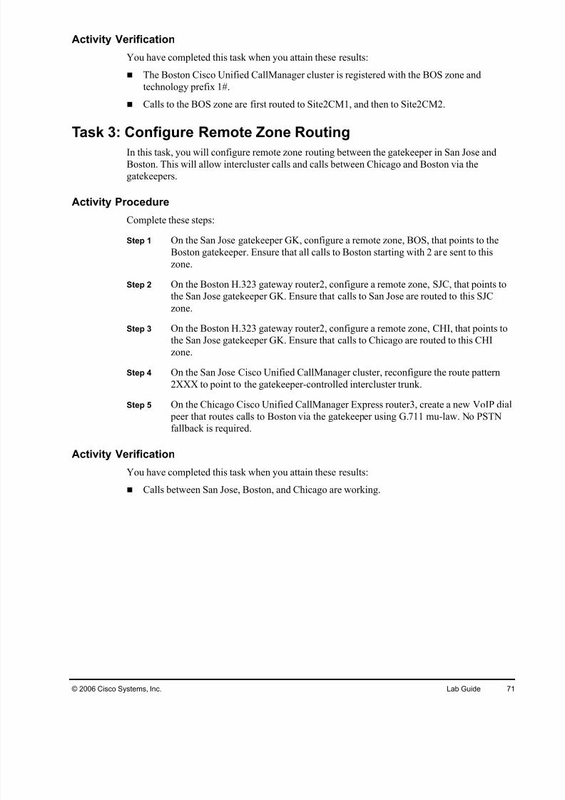
7/27/2019 Gwgk20lg - Gk Rc Modified
http://slidepdf.com/reader/full/gwgk20lg-gk-rc-modified 71/107
© 2006 Cisco Systems, Inc. Lab Guide 71
Activity Verification
You have completed this task when you attain these results:
The Boston Cisco Unified CallManager cluster is registered with the BOS zone and
technology prefix 1#.
Calls to the BOS zone are first routed to Site2CM1, and then to Site2CM2.
Task 3: Configure Remote Zone RoutingIn this task, you will configure remote zone routing between the gatekeeper in San Jose and
Boston. This will allow intercluster calls and calls between Chicago and Boston via the
gatekeepers.
Activity Procedure
Complete these steps:
Step 1 On the San Jose gatekeeper GK, configure a remote zone, BOS, that points to the
Boston gatekeeper. Ensure that all calls to Boston starting with 2 are sent to this
zone.
Step 2 On the Boston H.323 gateway router2, configure a remote zone, SJC, that points to
the San Jose gatekeeper GK. Ensure that calls to San Jose are routed to this SJC
zone.
Step 3 On the Boston H.323 gateway router2, configure a remote zone, CHI, that points to
the San Jose gatekeeper GK. Ensure that calls to Chicago are routed to this CHI
zone.
Step 4 On the San Jose Cisco Unified CallManager cluster, reconfigure the route pattern
2XXX to point to the gatekeeper-controlled intercluster trunk.
Step 5 On the Chicago Cisco Unified CallManager Express router3, create a new VoIP dial
peer that routes calls to Boston via the gatekeeper using G.711 mu-law. No PSTNfallback is required.
Activity Verification
You have completed this task when you attain these results:
Calls between San Jose, Boston, and Chicago are working.
7/27/2019 Gwgk20lg - Gk Rc Modified
http://slidepdf.com/reader/full/gwgk20lg-gk-rc-modified 72/107
72 Implementing Cisco Voice Gateways and Gatekeepers (GWGK) v2.0 © 2006 Cisco Systems, Inc.
Lab 5-4: Implementing Gatekeeper RedundancyComplete this lab activity to practice what you learned in the related module.
Activity Objective
In this activity, you will configure a redundant GUP cluster in San Jose. The cluster will use the
already-configured San Jose gatekeeper GK and another gatekeeper configured on the San JoseMGCP gateway router1. After completing this activity, you will be able to meet this objective:
Configure a GUP cluster and verify correct operation
Required Resources
These are the resources and equipment that are required to complete this activity:
San Jose Cisco Unified CallManager cluster
San Jose gatekeeper GK
San Jose MGCP gateway router1
San Jose IP phones
Boston IP phones
Chicago IP phones

7/27/2019 Gwgk20lg - Gk Rc Modified
http://slidepdf.com/reader/full/gwgk20lg-gk-rc-modified 73/107
© 2006 Cisco Systems, Inc. Lab Guide 73
Command List
The tables describe the commands that are used in this activity.
Gatekeeper Configuration Commands
Command Description
gatekeeper To enter gatekeeper configuration mode, use the gatekeeper command in global configuration mode.
zone local zone-namedomain-name [ras-IP-address]
Specifies a zone controlled by a gatekeeper with thesearguments:
gatekeeper-name: Specifies the gatekeeper name or zonename. This is usually the fully domain-qualified host nameof the gatekeeper. For example, if the domain name iscisco.com, the gatekeeper name might be gk1.cisco.com.However, if the gatekeeper is controlling multiple zones,the gatekeeper name for each zone should be someunique string that has a mnemonic value.
domain-name: Specifies the domain name served by thisgatekeeper.
ras-IP-address: (Optional) Specifies the IP address of oneof the interfaces on the gatekeeper. When the gatekeeper responds to gatekeeper discovery messages, it signalsthe endpoint or gateway to use this address in futurecommunications.
Note: Setting this address for one local zone makes it theaddress used for all local zones.
no shutdown Brings the gatekeeper online.
Router(config-gk)# zone prefix gatekeeper-name e164-prefix [ blast |seq ] [gw-priority priority gw-alias [gw-alias, ...]]
Adds a prefix to the gatekeeper zone list with these keywordsand arguments:
gatekeeper-name: Specifies the name of a local or remote
gatekeeper, which must have been defined by using thezone local or zone remote command.
e164-prefix : Specifies an E.164 prefix in standard formfollowed by dots (.). Each dot represents a number in theE.164 address. For example, 212....... is matched by 212and any 7 numbers.
Note: Although the preferred configuration method is to use adot to represent each digit in an E.164 address, you can alsoenter an asterisk (*) to match any number of digits.
blast: (Optional) If you list multiple hopoffs, this indicatesthat the LRQs should be sent simultaneously to thegatekeepers based on the order in which they were listed.The default is seq.
seq: (Optional) If you list multiple hopoffs, this indicatesthat the LRQs should be sent sequentially to thegatekeepers based on the order in which they were listed.The default is seq.
gw-priority priority gw-alias: (Optional) Use the gw-priority option to define how the gatekeeper selectsgateways in its local zone for calls to numbers that beginwith e164-prefix . Do not use this option to set prioritylevels for a prefix assigned to a remote gatekeeper.
Use values from 0 to 10. A 0 value prevents the gatekeeper

7/27/2019 Gwgk20lg - Gk Rc Modified
http://slidepdf.com/reader/full/gwgk20lg-gk-rc-modified 74/107
74 Implementing Cisco Voice Gateways and Gatekeepers (GWGK) v2.0 © 2006 Cisco Systems, Inc.
from using the gateway gw-alias for that prefix. Value 10places the highest priority on gateway gw-alias. If you do notspecify a priority value for a gateway, the value 5 is assigned.
To assign the same priority value for one prefix to multiplegateways, list all the gateway names after the pri-0-to-10 value.
The gw-alias name is the H.323 ID of a gateway that isregistered or will register with the gatekeeper. This name is seton the gateway with the h323-gateway voip h.323-idcommand.
Router(config-gk)# gw-type-prefix type-prefix [hopoff gkid1] [hopoffgkid2] [hopoff gkidn][seq | blast] [default-technology] [gw ipaddripaddr [ port]]
Adds technology prefix to the gatekeeper configuration list withthese keywords and arguments:
type-prefix : A technology prefix is recognized and isstripped before checking for the zone prefix. It is stronglyrecommended that you select technology prefixes that donot lead to ambiguity with zone prefixes. Do this by usingthe # character to terminate technology prefixes, such as3#..
hopoff gkid : (Optional) Use this option to specify thegatekeeper where the call is to hop off, regardless of thezone prefix in the destination address. The gkid argumentrefers to a gatekeeper previously configured using the
zone local or zone remote comment. You can enter thiskeyword and argument multiple times to configureredundant gatekeepers for a given technology prefix.
blast: (Optional) If you list multiple hopoffs, this indicatesthat the LRQs should be sent simultaneously to thegatekeepers based on the order in which they were listed.The default is seq.
seq: (Optional) If you list multiple hopoffs, this indicatesthat the LRQs should be sent sequentially to thegatekeepers based on the order in which they were listed.The default is seq.
default-technology : (Optional) Gateways registeringwith this prefix option are used as the default for routing
any addresses that are otherwise unresolved.
gw ipaddr ipaddr [ port ]: (Optional) Use this option toindicate that the gateway is incapable of registeringtechnology prefixes. When it registers, it adds thegateway to the group for this type prefix, just as if it hadsent the technology prefix in its registration. Thisparameter can be repeated to associate more than onegateway with a technology prefix.
zone cluster local cluster -name local-zone-name
Use the zone cluster local command in gatekeeper configuration mode to define a local grouping of gatekeepers,including the gatekeeper that you are configuring. Use the no form of this command to disable the local grouping of gatekeepers.
element gatekeeper -nameip-address [ port]
Use the element command in gatekeeper configuration modeto define component elements of local or remote clusters. Usethe no form of this command to disable component elementsof local or remote clusters.
show gatekeeper calls To display the status of each ongoing call of which agatekeeper is aware, use the show gatekeeper callscommand in privileged EXEC mode.
show gatekeeper status To display the overall gatekeeper status, including theauthorization and authentication status and the zone status,use the show gatekeeper status command in EXEC mode.

7/27/2019 Gwgk20lg - Gk Rc Modified
http://slidepdf.com/reader/full/gwgk20lg-gk-rc-modified 75/107
© 2006 Cisco Systems, Inc. Lab Guide 75
show gatekeeperendpoints
To display the status of all registered endpoints for agatekeeper, use the show gatekeeper endpoints commandin privileged EXEC mode.
show gatekeeper gw-type- prefix
To display the gateway technology prefix table, use the showgatekeeper gw-type-prefix command in privileged EXECmode.
show gatekeeper zone prefix [all]
To display the zone prefix table, use the show gatekeeper zone prefix command in privileged EXEC mode.
show gatekeeper zonestatus To display the status of zones related to a gatekeeper, use theshow gatekeeper zone status command in privileged EXECmode.
Gateway Configuration Commands
Command Description
gateway
Example:
Router(config)# gateway
Enters gateway configuration mode and enables thegateway to register with the gatekeeper.
h323-gateway voipinterface
Identifies this as a VoIP gateway interface.
h323-gateway voip id gatekeeper-id {ipaddr ip-address [port]| multicast}[priority priority ]
(Optional) Defines the name and location of the gatekeeper for this gateway with these keywords and arguments.
gatekeeper-id : The H.323 identification of thegatekeeper. This must exactly match the gatekeeper ID in the gatekeeper configuration. The recommendedformat is name.domainname.
ipaddr ip-address: The IP address to be used toidentify the gatekeeper.
port : The port number used.
multicast: The gateway uses multicast to locate the
gatekeeper.
priority priority : The priority of this gatekeeper. Theacceptable range is 1 to 127, and the default is 127.
h323-gateway voip h323-id interface-id
(Optional) Defines the H.323 name of the gateway,identifying this gateway to its associated gatekeeper.
Usually this ID is the name of the gateway, with thegatekeeper domain name appended to the end like this:name@domainname.
h323-gateway voip tech- prefix prefix
(Optional) Defines the numbers used as the technologyprefix that the gateway registers with the gatekeeper.
This command can contain up to 11 characters. Although it
is not strictly necessary, a pound symbol (#) is frequentlyused as the last digit in a prefix. Valid characters are 0 to 9,#, and *.
session target ras RAS signaling function protocol is being used, meaningthat a gatekeeper is consulted to translate the E.164address into an IP address.
Job Aids
There are no job aids for this activity.

7/27/2019 Gwgk20lg - Gk Rc Modified
http://slidepdf.com/reader/full/gwgk20lg-gk-rc-modified 76/107
76 Implementing Cisco Voice Gateways and Gatekeepers (GWGK) v2.0 © 2006 Cisco Systems, Inc.
Task 1: Configure a GUP Cluster
In this task, you will configure a GUP cluster using the San Jose gatekeeper GK and the Boston
MGCP gateway router2.
Activity Procedure
Complete these steps:
Step 1 On the San Jose MGCP gateway router 1, configure the local zones, CH1-router1
and SJC-router1 using the 192.168.P1.254 address as the IP address.
Step 2 On the San Jose router 1, configure a GUP cluster with a local cluster name SJC-
Cluster and the zone SJC-router1. The element for the GUP cluster should be the
San Jose gatekeeper router. Name this element SJC.
Step 3 On the San Jose router 1, configure a GUP cluster with a local cluster name CHI-
Cluster and the zone CHI-router1. The element for the GUP cluster should be the
San Jose gatekeeper router. Name this element CHI.
Step 4 On the San Jose gatekeeper GK, configure a GUP cluster with a local cluster name
SJC-Cluster and the zone SJC. The element for the GUP cluster should be the SanJose gateway router1. Name this element SJC-router1.
Step 5 On the San Jose gatekeeper GK, configure a GUP cluster with a local cluster name
CHI-Cluster and the zone CHI. The element for the GUP cluster should be the San
Jose gateway router1. Name this element CHI-router1.
Step 6 (optional if time) On the Boston router 2, modify the remote zone configuration so
that it is pointing to the remote cluster instead.
Activity Verification
You have completed this task when you attain these results:
Use debug gatekeeper gup and show gatekeeper clusters commands to verify your GUP
cluster configuration.
Place a call between a phone in the Chicago site and the Denver site Denver. Verify that the
GUP is working correctly.

7/27/2019 Gwgk20lg - Gk Rc Modified
http://slidepdf.com/reader/full/gwgk20lg-gk-rc-modified 77/107
© 2006 Cisco Systems, Inc. Lab Guide 77
Lab 6-1: Implementing IP-to-IP GatewaysComplete this lab activity to practice what you learned in the related module.
Activity Objective
In this activity, you will configure San Jose MGCP gateway router1 to also act as an IP-to-IP
gateway. The IP-to-IP gateway will be used for connections to a SIP carrier. After completingthis activity, you will be able to meet this objective:
Configure an IP-to-IP gateway for protocol interworking and address hiding.
Required Resources
These are the resources and equipment that are required to complete this activity:
San Jose Cisco Unified CallManager cluster
Boston Cisco Unified CallManager cluster
San Jose MGCP gateway router1
San Jose gatekeeper GK
Boston H.323 gateway router2, also configured as a gatekeeper

7/27/2019 Gwgk20lg - Gk Rc Modified
http://slidepdf.com/reader/full/gwgk20lg-gk-rc-modified 78/107
78 Implementing Cisco Voice Gateways and Gatekeepers (GWGK) v2.0 © 2006 Cisco Systems, Inc.
Command List
The table describes the commands that are used in this activity.
IPIPGW Configuration Commands
Command Description
allow-connections from-type to to-type
Enables protocol Interworking on an IP-to-IP gateway.
media [flow-around | flow-through]
Configures how media streams are handled on an IP-to-IPgateway in dial-peer, voice-class, or voice-serviceconfiguration mode.
codec transparent Enables codec capabilities to be passed transparentlybetween endpoints on an IP-to-IP gateway. This can alsobe configured in a voice class.
Job Aids
There are no job aids for this activity.
Task 1: Configure an IP-to-IP Gateway for ProtocolInterworking and Address Hiding
In this task, you will configure the San Jose MGCP gateway router1 to also act as an IP-to-IP
gateway. Calls to an SIP carrier will travel through the IP-to-IP gateway, with the internal call
leg being H.323.
Activity Procedure
Complete these steps:
Step 1 On the San Jose MGCP gateway router1, shut down the gatekeeper process.
Step 2 On the San Jose MGCP gateway router1, enable interworking between H.323 and
SIP.
Step 3 Ensure that the LAN interface is used for H.323 signaling.
Step 4 Create a new outbound SIP VoIP dial peer that will route calls to the SIP carrier.
192.168.10.254. The destination pattern should be a 9011T, G.711 mu-law codec.
Step 5 Create a new inbound H.323 VoIP dial peer that will accept calls from the San Jose
Cisco Unified CallManager cluster. Use a G.711 mu-law codec and an appropriate
incoming called number to ensure this dial peer is matched for inbound calls.
Step 6 Create a new sip-out voice translation profile that will strip off the leading 9011
used for international calls. Bind the profile to the VoIP dial peer pointing to the SIP
carrier for outbound calls.
Step 7 On the San Jose Cisco Unified CallManager cluster, add a new H.323 gateway that
will point to the San Jose IPIPGW gateway router1.
Step 8 Create a new route pattern 9011!# and specify the IP-to-IP gateway as the
destination.

7/27/2019 Gwgk20lg - Gk Rc Modified
http://slidepdf.com/reader/full/gwgk20lg-gk-rc-modified 79/107
© 2006 Cisco Systems, Inc. Lab Guide 79
Activity Verification
You have completed this task when you attain these results:
You can place a call from the San Jose Cisco Unified CallManager cluster to the
international PSTN phone. Use the show call active voice brief command to verify H.323-
to-SIP interworking.

7/27/2019 Gwgk20lg - Gk Rc Modified
http://slidepdf.com/reader/full/gwgk20lg-gk-rc-modified 80/107
80 Implementing Cisco Voice Gateways and Gatekeepers (GWGK) v2.0 © 2006 Cisco Systems, Inc.
Answer KeyThe correct answers and expected solutions for the activities that are described in this guide
appear here.
Lab 1-1 Answer Key: Implementing H.323 Gateways
When you complete this activity, your configuration will be similar to the results here, withdifferences that are specific to your device or workgroup.
Cisco IOS Configuration: router2
voice service voip
h323
!
interface FastEthernet0/0.P12
ip address 192.168.P2.254 255.255.255.0
h323-gateway voip interface
h323-gateway voip bind srcaddr 192.168.P2.254
!
voice class h323 1
h225 timeout tcp establish 3
dial-peer voice 21 voip
preference 1
destination-pattern 8575552...
voice-class h323 1
session target ipv4:192.168.P2.1
incoming called-number 9
codec g711ulaw
!
dial-peer voice 22 voip
preference 2
destination-pattern 8575552...
voice-class h323 1
session target ipv4:192.168.P2.2
incoming called-number 9

7/27/2019 Gwgk20lg - Gk Rc Modified
http://slidepdf.com/reader/full/gwgk20lg-gk-rc-modified 81/107
© 2006 Cisco Systems, Inc. Lab Guide 81
Cisco Unified CallManager Configuration
Lab 1-2 Answer Key: Implementing MGCP GatewaysWhen you complete this activity, your configuration will be similar to the results here, with
differences that are specific to your device or workgroup.
Cisco IOS Configuration: router1
ccm-manager mgcp
ccm-manager music-on-hold
ccm-manager config server 192.168.P1.1
ccm-manager config
!
mgcp
mgcp call-agent 192.168.P1.1 2427 service-type mgcp version 0.1
mgcp dtmf-relay voip codec all mode out-of-band
mgcp rtp unreachable timeout 1000 action notify
mgcp modem passthrough voip mode nse
mgcp package-capability rtp-package
no mgcp package-capability res-package
mgcp package-capability sst-package
no mgcp package-capability fxr-package
mgcp package-capability pre-package
no mgcp timer receive-rtcp
mgcp sdp simple
mgcp rtp payload-type g726r16 static
!
mgcp profile default

7/27/2019 Gwgk20lg - Gk Rc Modified
http://slidepdf.com/reader/full/gwgk20lg-gk-rc-modified 82/107
82 Implementing Cisco Voice Gateways and Gatekeepers (GWGK) v2.0 © 2006 Cisco Systems, Inc.
Cisco Unified CallManager Configuration
Lab 1-3 Answer Key: Implementing SIP GatewaysWhen you complete this activity, your configuration will be similar to the results here, with
differences that are specific to your device or workgroup.
Cisco IOS Configuration: router4
voice service voip
sip
!
dial-peer voice 9999 voip
destination-pattern 0Tsession protocol sipv2
session target ipv4:192.168.P10.254
Lab 2-1 Answer Key: Implementing Analog Trunks
When you complete this activity, your configuration will be similar to the results here, with
differences that are specific to your device or workgroup.
Cisco IOS Configuration: router3
voice-port 0/1/0
type 5
signal wink-start
!
dial-peer voice 42 pots
preference 2
destination-pattern 4...
port 0/1/0

7/27/2019 Gwgk20lg - Gk Rc Modified
http://slidepdf.com/reader/full/gwgk20lg-gk-rc-modified 83/107
© 2006 Cisco Systems, Inc. Lab Guide 83
forward-digits all
Cisco IOS Configuration: router4
voice-port 0/0/0
signal groundStart
connection plar opx 4002
!
voice-port 0/1/0type 5
signal wink-start
!
dial-peer voice 90 pots
destination-pattern 9T
port 0/0/0
!
dial-peer voice 32 pots
preference 2
destination-pattern 3...
port 0/1/0
forward-digits all
Lab 2-2 Answer Key: Implementing CAS Trunks
When you complete this activity, your configuration will be similar to the results here, with
differences that are specific to your device or workgroup.
Cisco IOS Configuration: router2
network-clock-participate wic 1
network-clock-select 1 T1 0/1/0
!
isdn switch-type primary-ni
!
controller T1 0/1/0
framing esf
linecode b8zs
ds0-group 0 timeslots 1-24 type e&m-immediate-start dtmf dnis
!
dial-peer voice 90 pots
destination-pattern 9T
direct-inward-dial
port 0/1/0:0

7/27/2019 Gwgk20lg - Gk Rc Modified
http://slidepdf.com/reader/full/gwgk20lg-gk-rc-modified 84/107
84 Implementing Cisco Voice Gateways and Gatekeepers (GWGK) v2.0 © 2006 Cisco Systems, Inc.
Lab 2-3 Answer Key: Implementing PRI Trunks
When you complete this activity, your configuration will be similar to the results here, with
differences that are specific to your device or workgroup.
Cisco IOS Configuration: router3
network-clock-participate wic 0
network-clock-select 1 E1 0/0/0!
isdn switch-type primary-net5
!
controller e1 0/0/0
pri-group timeslots 1-31
!
dial-peer voice 1 pots
destination-pattern 9T
direct-inward-dial
port 0/0/0:15
!
telephony-service
dialplan-pattern 1 3125553... extension-length 4
Lab 2-4 Answer Key: Implementing QSIG Trunks
When you complete this activity, your configuration will be similar to the results here, with
differences that are specific to your device or workgroup.
Cisco IOS Configuration: router2
controller E1 0/0/0
pri-group timeslots 1-31 service mgcp
!
interface Serial0/0/0:15
no ip address
encapsulation hdlc
isdn switch-type primary-qsig
isdn incoming-voice voice
isdn bind-l3 ccm-manager
no cdp enable
!
ccm-manager mgcp
ccm-manager music-on-hold
ccm-manager config server 192.168.P2.1
ccm-manager config

7/27/2019 Gwgk20lg - Gk Rc Modified
http://slidepdf.com/reader/full/gwgk20lg-gk-rc-modified 85/107
© 2006 Cisco Systems, Inc. Lab Guide 85
!
mgcp
mgcp call-agent 192.168.P2.1 2427 service-type mgcp version 0.1
mgcp dtmf-relay voip codec all mode out-of-band
mgcp rtp unreachable timeout 1000 action notify
mgcp modem passthrough voip mode nse
mgcp package-capability rtp-package
no mgcp package-capability res-package
mgcp package-capability sst-package
no mgcp package-capability fxr-package
mgcp package-capability pre-package
no mgcp timer receive-rtcp
mgcp sdp simple
mgcp rtp payload-type g726r16 static
!
mgcp profile default
Cisco IOS Configuration: router1
controller E1 0/0/1
pri-group timeslots 1-31 service mgcp
!
interface Serial0/0/1:15
no ip address
encapsulation hdlc
isdn switch-type primary-qsig
isdn protocol-emulate network
isdn incoming-voice voice
isdn T310 120000
isdn bind-l3 ccm-manager
no cdp enable

7/27/2019 Gwgk20lg - Gk Rc Modified
http://slidepdf.com/reader/full/gwgk20lg-gk-rc-modified 86/107
86 Implementing Cisco Voice Gateways and Gatekeepers (GWGK) v2.0 © 2006 Cisco Systems, Inc.
San Jose Cisco Unified CallManager Configuration
Boston Cisco Unified CallManager Configuration

7/27/2019 Gwgk20lg - Gk Rc Modified
http://slidepdf.com/reader/full/gwgk20lg-gk-rc-modified 87/107
© 2006 Cisco Systems, Inc. Lab Guide 87
Lab 3-1 Answer Key: Implementing PSTN Dial Plans on CiscoIOS Gateways
When you complete this activity, your configuration will be similar to the results here, with
differences that are specific to your device or workgroup.
Cisco IOS Configuration: router2
dial-peer voice 90 potsdestination-pattern 9T
direct-inward-dial
port 0/1/0:0
Cisco IOS Configuration: router3
!
!
voice translation-rule 1000
rule 1 /^312555/ //
!
voice translation-rule 1001
rule 1 /^/ /9/ type national national
!
voice translation-rule 1003
rule 1 /^3.../ /312555\0/
!
!
voice translation-profile pstn-in
translate calling 1001
translate called 1000
!
voice translation-profile pstn-out
translate calling 1003
!
voice-port 0/0/0:15
translation-profile incoming pstn-intranslation-profile outgoing pstn-out
!
dial-peer voice 90 pots
destination-pattern 9[2-9]......
incoming called-number 3...
direct-inward-dial
port 0/0/0:15

7/27/2019 Gwgk20lg - Gk Rc Modified
http://slidepdf.com/reader/full/gwgk20lg-gk-rc-modified 88/107
88 Implementing Cisco Voice Gateways and Gatekeepers (GWGK) v2.0 © 2006 Cisco Systems, Inc.
!
dial-peer voice 910 pots
destination-pattern 91[2-9]..[2-9]......
port 0/0/0:15
forward-digits 11
!
dial-peer voice 90110 pots
destination-pattern 9011T
port 0/0/0:15
prefix 011
!
dial-peer voice 911 pots
destination-pattern 911
port 0/0/0:15
prefix 911!
dial-peer voice 9911 pots
destination-pattern 9911
port 0/0/0:15
prefix 911
!Cisco IOS Configuration: router4
dial-peer voice 90 pots
destination-pattern 9[2-9]......
port 0/0/0
!
dial-peer voice 910 pots
destination-pattern 91[2-9]..[2-9]......
port 0/0/0
forward-digits 11
!
dial-peer voice 90110 pots
destination-pattern 9011T
port 0/0/0
prefix 011
!
dial-peer voice 911 pots
destination-pattern 911
port 0/0/0
forward-digits 3
7/27/2019 Gwgk20lg - Gk Rc Modified
http://slidepdf.com/reader/full/gwgk20lg-gk-rc-modified 89/107
© 2006 Cisco Systems, Inc. Lab Guide 89
!
dial-peer voice 9911 pots
destination-pattern 9911
port 0/0/0
forward-digits 3
Lab 3-2 Answer Key: Implementing Multisite Dial Plans on
Cisco IOS GatewaysWhen you complete this activity, your configuration will be similar to the results here, with
differences that are specific to your device or workgroup.
Cisco IOS Configuration: router3
voice class h323 1
h225 timeout tcp establish 3
!
interface FastEthernet0/0
ip address 192.168.P3.254 255.255.255.0
h323-gateway voip bind srcaddr 192.168.P3.254
!
dial-peer voice 10 voip
destination-pattern 1...
voice-class h323 1
session target ipv4:192.168.P1.1
codec g711ulaw
preference 0
!
dial-peer voice 11 voip
destination-pattern 1...
voice-class h323 1
session target ipv4:192.168.P1.2
codec g711ulaw
preference 1
!
dial-peer voice 12 pots
preference 2
destination-pattern 1...
port 0/0/0:15
forward-digits all
prefix 1408555
!
dial-peer voice 40 voip

7/27/2019 Gwgk20lg - Gk Rc Modified
http://slidepdf.com/reader/full/gwgk20lg-gk-rc-modified 90/107
90 Implementing Cisco Voice Gateways and Gatekeepers (GWGK) v2.0 © 2006 Cisco Systems, Inc.
preference 0
destination-pattern 4...
session target ipv4:192.168.P4.254
!
dial-peer voice 41 pots
preference 1
destination-pattern 4...
port 0/0/0:15
prefix 13035554
Cisco IOS Configuration: router4
interface FastEthernet0/0
ip address 192.168.P4.254 255.255.255.0
duplex auto
speed auto
h323-gateway voip interface
h323-gateway voip bind srcaddr 192.168.P4.254
!
dial-peer voice 30 voip
destination-pattern 3...
session target ipv4:192.168.3.254
!
dial-peer voice 31 pots
preference 1
destination-pattern 3...
port 0/0/0
prefix 13125553
!
San Jose Cisco Unified CallManager Configuration
7/27/2019 Gwgk20lg - Gk Rc Modified
http://slidepdf.com/reader/full/gwgk20lg-gk-rc-modified 91/107
© 2006 Cisco Systems, Inc. Lab Guide 91
Lab 3-3 Answer Key: Implementing RSVP-Based CAC
When you complete this activity, your configuration will be similar to the results here, with
differences that are specific to your device or workgroup.
Cisco IOS Configuration: router3
call rsvp-sync resv-timer 3
!
interface FastEthernet0/1
ip address 192.168.P10.3 255.255.255.0
duplex auto
speed auto
ip rsvp bandwidth 100
!
dial-peer voice 40 voip
destination-pattern 4...
session target ipv4:192.168.P4.254
req-qos guaranteed-delay
acc-qos guaranteed-delay
!
Cisco IOS Configuration: router4
call rsvp-sync resv-timer 3
!
interface FastEthernet0/1
ip address 192.168.P10.4 255.255.255.0
duplex auto
speed auto
ip rsvp bandwidth 100
!
dial-peer voice 30 voip
destination-pattern 3...
session target ipv4:192.168.P3.254
req-qos guaranteed-delay
acc-qos guaranteed-delay
!
Lab 3-4 Answer Key: Implementing Calling Privileges on CiscoIOS Gateways
When you complete this activity, your configuration will be similar to the results here, with
differences that are specific to your device or workgroup.

7/27/2019 Gwgk20lg - Gk Rc Modified
http://slidepdf.com/reader/full/gwgk20lg-gk-rc-modified 92/107
92 Implementing Cisco Voice Gateways and Gatekeepers (GWGK) v2.0 © 2006 Cisco Systems, Inc.
Cisco IOS Configuration: router3
dial-peer cor custom
name local
name international
name national
name emergency
!
dial-peer cor list emergencycall
member emergency
!
dial-peer cor list localcall
member local
!
dial-peer cor list nationalcall
member national
!dial-peer cor list internationalcall
member international
!
dial-peer cor list local
member local
member emergency
!
dial-peer cor list national
member local
member national
member emergency
!
dial-peer cor list international
member local
member international
member national
member emergency
!
dial-peer voice 90 pots
corlist outgoing localcall
destination-pattern 9[2-9]......
incoming called-number 3...
direct-inward-dial
port 0/0/0:15

7/27/2019 Gwgk20lg - Gk Rc Modified
http://slidepdf.com/reader/full/gwgk20lg-gk-rc-modified 93/107
© 2006 Cisco Systems, Inc. Lab Guide 93
!
dial-peer voice 910 pots
corlist outgoing nationalcall
destination-pattern 91[2-9]..[2-9]......
port 0/0/0:15
forward-digits 11
!
dial-peer voice 90110 pots
corlist outgoing internationalcall
destination-pattern 9011T
port 0/0/0:15
prefix 011
!
dial-peer voice 911 pots
corlist outgoing emergencycall
destination-pattern 911port 0/0/0:15
forward-digits 3
!
dial-peer voice 9911 pots
corlist outgoing emergencycall
destination-pattern 9911
port 0/0/0:15
forward-digits 3
!
ephone-dn 1 dual-line
number 3001
description 13125553001
name Chicago Phone3-1
corlist incoming international
!
ephone-dn 2 dual-line
number 3002
description 13125553002
name Chicago Phone3-2
corlist incoming national
!
Lab 4-1 Answer Key: Implementing SRST Gateways
When you complete this activity, your configuration will be similar to the results here, with
differences that are specific to your device or workgroup.

7/27/2019 Gwgk20lg - Gk Rc Modified
http://slidepdf.com/reader/full/gwgk20lg-gk-rc-modified 94/107
94 Implementing Cisco Voice Gateways and Gatekeepers (GWGK) v2.0 © 2006 Cisco Systems, Inc.
San Jose Cisco Unified CallManager Configuration

7/27/2019 Gwgk20lg - Gk Rc Modified
http://slidepdf.com/reader/full/gwgk20lg-gk-rc-modified 95/107
© 2006 Cisco Systems, Inc. Lab Guide 95
Cisco IOS Configuration: router1
ccm-manager fallback-mgcp
!
dial-peer voice 9 pots
destination-pattern 9T
direct-inward-dial
port 0/0/0:15
!
call-manager-fallback
max-conferences 8 gain -6
ip source-address 192.168.P6.254 port 2000
max-ephones 24
max-dn 48 dual-line
dialplan-pattern 1 4085551... extension-length 4

7/27/2019 Gwgk20lg - Gk Rc Modified
http://slidepdf.com/reader/full/gwgk20lg-gk-rc-modified 96/107
96 Implementing Cisco Voice Gateways and Gatekeepers (GWGK) v2.0 © 2006 Cisco Systems, Inc.
Lab 4-2 Answer Key: Implementing Media Resources UsingCisco IOS Gateway DSPs
When you complete this activity, your configuration will be similar to the results here, with
differences that are specific to your device or workgroup.
Cisco IOS Configuration: router1
voice-card 0dspfarm
dsp services dspfarm
!
sccp local FastEthernet0/0.P11
sccp ccm 192.168.P1.1 identifier 1
sccp
!
sccp ccm group 1
bind interface FastEthernet0/0.P11
associate ccm 1 priority 1
associate profile 2 register CFBrouter1
associate profile 1 register XCODERrouter1
!
dspfarm profile 1 transcode
codec g711ulaw
codec g711alaw
codec g729ar8
codec g729abr8
codec g729br8
codec g729r8
maximum sessions 2
associate application SCCP
no shutdown
!

7/27/2019 Gwgk20lg - Gk Rc Modified
http://slidepdf.com/reader/full/gwgk20lg-gk-rc-modified 97/107
© 2006 Cisco Systems, Inc. Lab Guide 97
dspfarm profile 2 conference
codec g711ulaw
codec g711alaw
codec g729ar8
codec g729abr8
codec g729br8
codec g729r8
maximum sessions 1
associate application SCCP
no shutdown
San Jose Cisco Unified CallManager Configuration
7/27/2019 Gwgk20lg - Gk Rc Modified
http://slidepdf.com/reader/full/gwgk20lg-gk-rc-modified 98/107
98 Implementing Cisco Voice Gateways and Gatekeepers (GWGK) v2.0 © 2006 Cisco Systems, Inc.

7/27/2019 Gwgk20lg - Gk Rc Modified
http://slidepdf.com/reader/full/gwgk20lg-gk-rc-modified 99/107
© 2006 Cisco Systems, Inc. Lab Guide 99
Lab 4-3 Answer Key: Implementing Call Applications on CiscoIOS Gateways
When you complete this activity, your configuration will be similar to the results here, with
differences that are specific to your device or workgroup.
Cisco IOS Configuration: router4
applicationservice aa flash:its-CISCO.2.0.1.0.tcl
param operator 4002
paramspace english language en
paramspace english index 0
paramspace english location flash:
paramspace english prefix en
param aa-pilot 4000
!
voice-port 0/0/0
signal groundStart
!
dial-peer voice 90 pots
service aa
destination-pattern 9[2-9]......
port 0/0/0

7/27/2019 Gwgk20lg - Gk Rc Modified
http://slidepdf.com/reader/full/gwgk20lg-gk-rc-modified 100/107
100 Implementing Cisco Voice Gateways and Gatekeepers (GWGK) v2.0 © 2006 Cisco Systems, Inc.
Lab 5-1 Answer Key: Implementing Basic Gatekeeper Functionality
When you complete this activity, your configuration will be similar to the results here, with
differences that are specific to your device or workgroup.
Cisco IOS Configuration: Gatekeeper
gatekeeperzone local SJC cisco.com 192.168.P1.3
zone local CHI cisco.com
zone prefix CHI 3*
zone prefix SJC 1* gw-priority 10 GK-ICT_1
zone prefix SJC 1* gw-priority 9 GK-ICT_2
gw-type-prefix 1#* default-technology
no shutdown
Cisco IOS Configuration: router3
interface FastEthernet0/0
ip address 192.168.P3.254 255.255.255.0
duplex auto
speed auto
h323-gateway voip interface
h323-gateway voip id CHI ipaddr 192.168.P1.3 1719
h323-gateway voip h323-id CHI-CME
h323-gateway voip tech-prefix 1#
h323-gateway voip bind srcaddr 192.168.P3.254
!
gateway
!
dial-peer voice 10 voip
destination-pattern 1...
session target ras
!
dial-peer voice 11 voip
destination-pattern 1...session target ras
!
telephony-service
dialplan-pattern 1 3125553... extension-length 4 no-reg
!
!
ephone-dn 1 dual-line

7/27/2019 Gwgk20lg - Gk Rc Modified
http://slidepdf.com/reader/full/gwgk20lg-gk-rc-modified 101/107
© 2006 Cisco Systems, Inc. Lab Guide 101
number 3001 no-reg both
!
ephone-dn 2 dual-line
number 3002 no-reg both
San Jose Cisco Unified CallManager Configuration

7/27/2019 Gwgk20lg - Gk Rc Modified
http://slidepdf.com/reader/full/gwgk20lg-gk-rc-modified 102/107
102 Implementing Cisco Voice Gateways and Gatekeepers (GWGK) v2.0 © 2006 Cisco Systems, Inc.
Lab 5-2 Answer Key: Implementing Gatekeeper-Based CAC
When you complete this activity, your configuration will be similar to the results here, with
differences that are specific to your device or workgroup.
Cisco IOS Configuration: Gatekeeper
gatekeeper
bandwidth interzone zone SJC 128bandwidth interzone zone CHI 128
no shutdown
Lab 5-3 Answer Key: Configuring Remote Zones
When you complete this activity, your configuration will be similar to the results here, with
differences that are specific to your device or workgroup.
Cisco IOS Configuration: router2
gatekeeper
zone local BOS cisco.com 192.168.P10.2
zone remote SJC cisco.com 192.168.P1.3 1719
zone remote CHI cisco.com 192.168.P1.3 1719
zone prefix SJC 1*
zone prefix BOS 2* gw-priority 10 GK-ICT_1
zone prefix BOS 2* gw-priority 9 GK-ICT_2
zone prefix CHI 3*
gw-type-prefix 1#* default-technology
no shutdown
Cisco IOS Configuration: Gatekeeper
gatekeeper
zone remote BOS cisco.com 192.168.P10.2 1719
zone prefix BOS 2*
no shutdown
Cisco IOS Configuration: router3
dial-peer voice 2 voip
destination-pattern 2...
session target ras
codec g711ulaw

7/27/2019 Gwgk20lg - Gk Rc Modified
http://slidepdf.com/reader/full/gwgk20lg-gk-rc-modified 103/107
© 2006 Cisco Systems, Inc. Lab Guide 103
Boston Cisco Unified CallManager Configuration
7/27/2019 Gwgk20lg - Gk Rc Modified
http://slidepdf.com/reader/full/gwgk20lg-gk-rc-modified 104/107
104 Implementing Cisco Voice Gateways and Gatekeepers (GWGK) v2.0 © 2006 Cisco Systems, Inc.
San Jose Cisco Unified CallManager Configuration
Lab 5-4 Answer Key: Implementing Gatekeeper RedundancyWhen you complete this activity, your configuration will be similar to the results here, with
differences that are specific to your device or workgroup.
Cisco IOS Configuration: router1
gatekeeper
zone local CHI-router1 cisco.com 192.168.P1.254
zone local SJC-router1 cisco.com
zone prefix SJC-router1 1*
zone prefix CHI-router1 3*zone prefix BOS 2*
gw-type-prefix 1#* default-technology
zone cluster local SJC-Cluster SJC-router1
element SJC 192.168.P1.3 1719
!
zone cluster local CHI-Cluster CHI-router1
element CHI 192.168.P1.3 1719
!
no shutdown
Cisco IOS Configuration: Gatekeeper
gatekeeper
zone local SJC cisco.com 192.168.P1.3
zone local CHI cisco.com
zone remote BOS cisco.com 192.168.P10.2 1719

7/27/2019 Gwgk20lg - Gk Rc Modified
http://slidepdf.com/reader/full/gwgk20lg-gk-rc-modified 105/107
© 2006 Cisco Systems, Inc. Lab Guide 105
zone cluster local SJC-Cluster SJC
element SJC-router1 192.168.P1.254 1719
!
zone cluster local CHI-Cluster CHI
element CHI-router1 192.168.P1.254 1719
!
zone prefix SJC 1* gw-priority 10 GK-ICT_1
zone prefix SJC 1* gw-priority 9 GK-ICT_2
zone prefix BOS 2*
zone prefix CHI 3*
gw-type-prefix 1#* default-technology
bandwidth interzone zone SJC 128
bandwidth interzone zone CHI 128
no shutdown
Cisco IOS Configuration: R2 Boston (optional)
!gatekeeperzone local BOS cisco.com 192.168.P10.2zone cluster remote SJC-Cluster cisco.comelement SJC 192.168.P1.3 1719element SJC-router1 192.168.P1.254 1719!zone cluster remote CHI-Cluster cisco.comelement CHI-router1 192.168.P1.254 1719element CHI 192.168.P1.3 1719!zone prefix SJC-Cluster 1*zone prefix BOS 2* gw-priority 10 GK-ICT_1zone prefix BOS 2* gw-priority 9 GK-ICT_2zone prefix CHI-Cluster 3*gw-type-prefix 1#* default-technologyno shutdown
!

7/27/2019 Gwgk20lg - Gk Rc Modified
http://slidepdf.com/reader/full/gwgk20lg-gk-rc-modified 106/107
106 Implementing Cisco Voice Gateways and Gatekeepers (GWGK) v2.0 © 2006 Cisco Systems, Inc.
Lab 6-1 Answer Key: Implementing IP-to-IP Gateways
When you complete this activity, your configuration will be similar to the results here, with
differences that are specific to your device or workgroup.
Cisco IOS Configuration: router1
voice service voip
allow-connections h323 to sip
allow-connections sip to h323
!
voice translation-rule 9011
rule 1 /^9011/ //
!
voice translation-profile sip-out
translate called 9011
!
interface FastEthernet0/0
ip address 192.168.P1.254 255.255.255.0
duplex auto
speed auto
h323-gateway voip interface
!
dial-peer voice 9011 voip
translation-profile outgoing sip-out
destination-pattern 9011T
session protocol sipv2
session target ipv4:192.168.P10.254
codec g711ulaw
!
dial-peer voice 9012 voip
session target ipv4:192.168.P1.1
answer-address 1...
codec g711ulaw

7/27/2019 Gwgk20lg - Gk Rc Modified
http://slidepdf.com/reader/full/gwgk20lg-gk-rc-modified 107/107
San Jose Cisco Unified CallManager Configuration