Gusmer GH-2 and GH-4 Hydraulic Proportioner€¦ · Hydraulic Proportioner Hydraulic, heated,...
110
3A5376K EN Instructions Gusmer ® GH-2 and GH-4 Hydraulic Proportioner Hydraulic, heated, plural-component proportioner for spraying polyurethane foam. Not for outdoor use. For professional use only. Not approved for use in explosive atmospheres or hazardous (classified) locations. See page 3 for model information, including maximum working pressure and approvals. Important Safety Instructions Read all warnings and instructions in this manual and in your component manuals before using this equipment. Save all instructions.
Transcript of Gusmer GH-2 and GH-4 Hydraulic Proportioner€¦ · Hydraulic Proportioner Hydraulic, heated,...

3A5376KEN
Instructions
Gusmer® GH-2 and GH-4 Hydraulic Proportioner
Hydraulic, heated, plural-component proportioner for spraying polyurethane foam. Not for outdoor use. For professional use only.
Not approved for use in explosive atmospheres or hazardous (classified) locations.
See page 3 for model information, including maximum working pressure and approvals.
Important Safety InstructionsRead all warnings and instructions in this manual and in your component manuals before using this equipment. Save all instructions.

2 3A5376K
ContentsModels . . . . . . . . . . . . . . . . . . . . . . . . . . . . . . . . . . . . . . . . . 3
System Packages . . . . . . . . . . . . . . . . . . . . . . . . . . . . . 4Accessories. . . . . . . . . . . . . . . . . . . . . . . . . . . . . . . . . . . . . 6Supplied Manuals . . . . . . . . . . . . . . . . . . . . . . . . . . . . . . . . 6Related Manuals . . . . . . . . . . . . . . . . . . . . . . . . . . . . . . . . . 6Warnings . . . . . . . . . . . . . . . . . . . . . . . . . . . . . . . . . . . . . . . 7Important Isocyanate (ISO) Information . . . . . . . . . . . . . 11
Isocyanate Conditions . . . . . . . . . . . . . . . . . . . . . . . . . 11Material Self-ignition . . . . . . . . . . . . . . . . . . . . . . . . . . 12Keep Components A and B Separate . . . . . . . . . . . . . 12Moisture Sensitivity of Isocyanates . . . . . . . . . . . . . . . 12Foam Resins with 245 fa Blowing Agents . . . . . . . . . . 12Changing Materials . . . . . . . . . . . . . . . . . . . . . . . . . . . 12
Typical Installation . . . . . . . . . . . . . . . . . . . . . . . . . . . . . . 13Without circulation . . . . . . . . . . . . . . . . . . . . . . . . . . . . 13With proportioner manifold to drum circulation . . . . . . 14With gun manifold to drum circulation . . . . . . . . . . . . . 15
Component Identification. . . . . . . . . . . . . . . . . . . . . . . . . 16Control Panel . . . . . . . . . . . . . . . . . . . . . . . . . . . . . . . . 18
Installation . . . . . . . . . . . . . . . . . . . . . . . . . . . . . . . . . . . . . 20Mounting the System . . . . . . . . . . . . . . . . . . . . . . . . . . 20
Setup . . . . . . . . . . . . . . . . . . . . . . . . . . . . . . . . . . . . . . . . . 21Grounding . . . . . . . . . . . . . . . . . . . . . . . . . . . . . . . . . . 21General Equipment Guidelines . . . . . . . . . . . . . . . . . . 21Connect Power . . . . . . . . . . . . . . . . . . . . . . . . . . . . . . 22TSL Pump Lubrication System Setup . . . . . . . . . . . . . 24Install Fluid Temperature Sensor. . . . . . . . . . . . . . . . . 24Install Heated Hose to Proportioner. . . . . . . . . . . . . . . 25Adjust Hose Transformer Wiring . . . . . . . . . . . . . . . . . 26Flush Before Using Equipment . . . . . . . . . . . . . . . . . . 27Connect Feed Pumps . . . . . . . . . . . . . . . . . . . . . . . . . 27
Startup . . . . . . . . . . . . . . . . . . . . . . . . . . . . . . . . . . . . . . . . 28Digital Temperature Controllers . . . . . . . . . . . . . . . . . . 31Set Cycle Countdown . . . . . . . . . . . . . . . . . . . . . . . . . 32
Fluid Circulation . . . . . . . . . . . . . . . . . . . . . . . . . . . . . . . . 33Connect Proportioner Manifold to Drum
Circulation. . . . . . . . . . . . . . . . . . . . . . . . . . . . . . . 33Connect Gun Manifold to Drum Circulation . . . . . . . . . 34Reduce Hydraulic Pressure . . . . . . . . . . . . . . . . . . . . . 35
Spraying. . . . . . . . . . . . . . . . . . . . . . . . . . . . . . . . . . . . . . . 36Spray Adjustments. . . . . . . . . . . . . . . . . . . . . . . . . . . . 38
Standby . . . . . . . . . . . . . . . . . . . . . . . . . . . . . . . . . . . . . . . 39Shutdown. . . . . . . . . . . . . . . . . . . . . . . . . . . . . . . . . . . . . . 39Pressure Relief Procedure . . . . . . . . . . . . . . . . . . . . . . . . 41Flushing . . . . . . . . . . . . . . . . . . . . . . . . . . . . . . . . . . . . . . . 42Maintenance . . . . . . . . . . . . . . . . . . . . . . . . . . . . . . . . . . . 43
Preventative Maintenance Schedule . . . . . . . . . . . . . . 43Proportioner Maintenance . . . . . . . . . . . . . . . . . . . . . . 43Clean Fluid Inlet Filters . . . . . . . . . . . . . . . . . . . . . . . . 44TSL Pump Lubrication System . . . . . . . . . . . . . . . . . . 45
Troubleshooting . . . . . . . . . . . . . . . . . . . . . . . . . . . . . . . . 46
Online Troubleshooting . . . . . . . . . . . . . . . . . . . . . . . . 46Hydraulic Drive System . . . . . . . . . . . . . . . . . . . . . . . . 46Proportioning System . . . . . . . . . . . . . . . . . . . . . . . . . 48Hose Heat System. . . . . . . . . . . . . . . . . . . . . . . . . . . . 52Primary Heater. . . . . . . . . . . . . . . . . . . . . . . . . . . . . . . 56Pressure Monitor . . . . . . . . . . . . . . . . . . . . . . . . . . . . . 58
Repair. . . . . . . . . . . . . . . . . . . . . . . . . . . . . . . . . . . . . . . . . 60Repair Proportioning Pumps . . . . . . . . . . . . . . . . . . . . 60Change Hydraulic Fluid and Filter . . . . . . . . . . . . . . . . 61Replace Electric Motor or Belt . . . . . . . . . . . . . . . . . . . 62Replace Pressure Transducers . . . . . . . . . . . . . . . . . . 65Replace Primary Heater . . . . . . . . . . . . . . . . . . . . . . . 66Repair Heater Overtemperature Switch. . . . . . . . . . . . 67Replace Thermocouple . . . . . . . . . . . . . . . . . . . . . . . . 68Diagnose Heated Hose . . . . . . . . . . . . . . . . . . . . . . . . 70Repair Fluid Temperature Sensor (FTS) . . . . . . . . . . . 72Diagnose and Replace Hose Transformer . . . . . . . . . 73Replace Power Supply . . . . . . . . . . . . . . . . . . . . . . . . 74Replace Power Supply Fuse . . . . . . . . . . . . . . . . . . . . 74Replace Surge Protector . . . . . . . . . . . . . . . . . . . . . . . 75Replace Pressure Monitor Board. . . . . . . . . . . . . . . . . 76
Parts . . . . . . . . . . . . . . . . . . . . . . . . . . . . . . . . . . . . . . . . . . 78Proportioner . . . . . . . . . . . . . . . . . . . . . . . . . . . . . . . . . 78Proportioner Assembly . . . . . . . . . . . . . . . . . . . . . . . . 84Hydraulic Cylinder . . . . . . . . . . . . . . . . . . . . . . . . . . . . 88Fluid Manifold . . . . . . . . . . . . . . . . . . . . . . . . . . . . . . . 89Heater . . . . . . . . . . . . . . . . . . . . . . . . . . . . . . . . . . . . . 90Fluid Inlet Kits . . . . . . . . . . . . . . . . . . . . . . . . . . . . . . . 92Electrical Enclosure . . . . . . . . . . . . . . . . . . . . . . . . . . . 93Breaker Module . . . . . . . . . . . . . . . . . . . . . . . . . . . . . . 94Control Panel . . . . . . . . . . . . . . . . . . . . . . . . . . . . . . . . 95
Performance Charts . . . . . . . . . . . . . . . . . . . . . . . . . . . . . 96Foam Performance Chart . . . . . . . . . . . . . . . . . . . . . . 96Heater Performance Chart. . . . . . . . . . . . . . . . . . . . . . 97
Electrical Schematics . . . . . . . . . . . . . . . . . . . . . . . . . . . . 98Wire Connection . . . . . . . . . . . . . . . . . . . . . . . . . . . . . 98Heater Wiring. . . . . . . . . . . . . . . . . . . . . . . . . . . . . . . 100Motor Relay Wiring . . . . . . . . . . . . . . . . . . . . . . . . . . 101Control Power Wiring. . . . . . . . . . . . . . . . . . . . . . . . . 102Pump Control Wiring . . . . . . . . . . . . . . . . . . . . . . . . . 103Single Phase Power Wiring . . . . . . . . . . . . . . . . . . . . 104Three Phase (230 V) Power Wiring . . . . . . . . . . . . . . 104GH-2 Three Phase (400 V) Power Wiring . . . . . . . . . 105GH-4 Three Phase (400 V) Power Wiring . . . . . . . . . 105
Dimensions . . . . . . . . . . . . . . . . . . . . . . . . . . . . . . . . . . . 106Technical Specifications . . . . . . . . . . . . . . . . . . . . . . . . 108California Proposition 65 . . . . . . . . . . . . . . . . . . . . . . . . 109Graco Extended Warranty . . . . . . . . . . . . . . . . . . . . . . . 110

Models
3A5376K 3
ModelsNOTE: All models require standard 2-component hose with thermocouple cable.
GH-2 Models (10 kW)
GH-4 Models (15 kW)
Proportioner 26C200 26C201 26C202 26C699 26C700
Configurable Voltage Phase (VAC, 50/60 Hz)
200-240 VAC
1Ø
200-240 VAC
3ØΔ
350-415 VAC
3ØY
200-240 VAC
3ØΔ
350-415 VAC
3ØY
Full Load Peak Current*
79 46 35 67 41
Maximum Fluid Working Pressure
2000 psi
(14 MPa, 140 bar)
Approximate Output per Cycle (A + B)
0.074 gal.
(0.28 L)
0.063 gal.
(0.24 L)
Maximum Flow Rate
28 lb/min
12.7 kg/min
45 lb/min
20 kg/min
Total System Load†
17,960 W 26,600 W
Agency Approvals
* Full load amps with all devices operating at maximum capabilities. Fuse requirements at various flow rates and mix chamber sizes may be less.
† Total system watts used by system, based on maximum heated hose length for each unit.
• GH-2 series: 310 ft (94.5 m) maximum heated hose length, including whip hose.
• GH-4 series: 410 ft (125.0 m) maximum heated hose length, including whip hose.
Voltage Configurations Key
Ø PHASE
Δ DELTA
Y WYE

Models
4 3A5376K
System Packages
Standard System Packages
NOTE: Packages AXXXXX include the Fusion AP gun. Packages CXXXXX include the Fusion CS gun. Packages PXXXXX include the Probler P2 gun.
NOTE: The standard hose length is 50 ft (15 m) and the standard whip hose is 10 ft (3 m).
Standard System Packages
Proportioner ConfigurationStandard Package
P/N
Agency Approvals
Gun P/N (Qty.)
Hose P/N (Qty.)
Whip Hose (Qty.)
GH-2 (10 kW)
200-240 V
1-Phase
26C200 APC200 246102 (1)
246678 (1)
25P770 (1)
26C200 CSC200 CS02RD (1)
26C200 P2C200 GCP2R2 (1)
26C200 FPC200 25P589 (2)
3-Phase
26C201 APC201 246102 (1)
26C201 CSC201 CS02RD (1)
26C201 P2C201 GCP2R2 (1)
26C201 FPC201 25P589 (2)
350-415 V
3-Phase/Neutral
26C202 APC202 246102 (1)
26C202 CSC202 CS02RD (1)
26C202 P2C202 GCP2R2 (1)
26C202 FPC202 25P589 (2)
GH-4 (15 kW)
200-240 V
3-Phase
26C699 APC699 246102 (1)
246678 (1)
25P770 (1)
26C699 P2C699 GCP2R3 (1)
26C699 FPC699 25R085 (3)
350-415 V
3-Phase/Neutral
26C700 APC700 246102 (1)
26C700 P2C700 GCP2R3 (1)
26C700 FPC700 25R085 (3)

Models
3A5376K 5
Multi-Hose System Packages
NOTE: Packages AXXXXX include the Fusion AP gun. Packages CXXXXX include the Fusion CS gun. Packages PXXXXX include the Probler P2 gun.
NOTE: The standard hose length is 50 ft (15 m) and the standard whip hose is 10 ft (3 m).
Multi-Hose System Packages
Proportioner Configuration
Multi-Hose
Package P/N
Agency Approvals
Gun P/N (Qty.)
Hose P/N (Qty.)
Whip Hose (Qty.)
GH-2 (10 kW)
200-240 V
1-Phase
26C200 AHC200 246102 (1)
246678 (5)
25P770 (1)
26C200 CHC200 CS02RD (1)
26C200 PHC200 GCP2R2 (1)
26C200 FHC200 25P589 (1)
3-Phase
26C201 AHC201 246102 (1)
26C201 CHC201 CS02RD (1)
26C201 PHC201 GCP2R2 (1)
26C201 FHC201 25P589 (1)
350-415 V
3-Phase/Neutral
26C202 AHC202 246102 (1)
26C202 CHC202 CS02RD (1)
26C202 PHC202 GCP2R2 (1)
26C202 FHC202 25P589 (1)
GH-4 (15 kW)
200-240 V
3-Phase
26C699 AHC699 246102 (1)
246678 (6)
25P770 (1)
26C699 PHC699 GCP2R3 (1)
26C699 FHC699 25R085 (1)
350-415 V
3-Phase/Neutral
26C700 AHC700 246102 (1)
26C700 PHC700 GCP2R3 (1)
26C700 FHC700 25R085 (1)

Accessories
6 3A5376K
Accessories
Supplied ManualsThe following manuals are shipped with the Gusmer Hydraulic Proportioner. Refer to these manuals for detailed equipment information.
Manuals are also available at www.graco.com.
Related ManualsThe following manuals are for accessories used with the Gusmer Hydraulic Proportioner.
Component Manuals in English
Kit Number Description
17G340 Caster Kit
24M174 Drum Level Sticks
Manual Description
3A5376 Gusmer Hydraulic Proportioner Manual
Manual in English Description
Displacement Pump Manual
3A3085 Pump, Repair-Parts
312071 Seal Kit
Feed System Manuals
309572 Heated Hose, Instructions-Parts
309852 Circulation and Return Tube Kit, Instructions-Parts
309815 Feed Pump Kits, Instructions-Parts
309827 Feed Pump Air Supply Kit, Instructions-Parts
Spray Gun Manuals
309550 Fusion® AP Gun
312666 Fusion CS Gun
3A7314 Fusion PC Gun
313213 Probler® P2 Gun
Accessory Manuals
3A3010 Caster Kit, Instructions-Parts
Component Manuals
312070 Circulation Valve Kit

Warnings
3A5376K 7
WarningsThe following warnings are for the setup, use, grounding, maintenance, and repair of this equipment. The exclamation point symbol alerts you to a general warning and the hazard symbols refer to procedure-specific risks. When these symbols appear in the body of this manual or on warning labels, refer back to these Warnings. Product-specific hazard symbols and warnings not covered in this section may appear throughout the body of this manual where applicable.
DANGERSEVERE ELECTRIC SHOCK HAZARDThis equipment can be powered by more than 240 V. Contact with this voltage will cause death or serious injury.
• Turn off and disconnect power at main switch before disconnection any cables and before servicing equipment.
• This equipment must be grounded. Connect only to grounded power source.• All electrical wiring must be done by a qualified electrician and comply with all local codes and
regulations.• Do not expose to rain. Store indoors.
WARNINGTOXIC FLUID OR FUMES HAZARDToxic fluids or fumes can cause serious injury or death if splashed in the eyes or on skin, inhaled or swallowed.
• Read Safety Data Sheets (SDSs) for handling instructions and to know the specific hazards of the fluids you are using, including the effects of long-term exposure.
• When spraying, servicing equipment, or when in the work area, always keep work area well-ventilated and always wear appropriate personal protective equipment. See Personal Protective Equipment warnings in this manual.
• Store hazardous fluid in approved containers, and dispose of it according to applicable guidelines.
PERSONAL PROTECTIVE EQUIPMENTAlways wear appropriate personal protective equipment and cover all skin when spraying, servicing equipment, or when in the work area. Protective equipment helps prevent serious injury, including long-term exposure; inhalation of toxic fumes, mists or vapors; allergic reaction; burns; eye injury and hearing loss. This protective equipment includes but is not limited to:
• A properly fitting respirator, which may include a supplied-air respirator, chemically impermeable gloves, protective clothing and foot coverings as recommended by the fluid manufacturer and local regulatory authority.
• Protective eyewear and hearing protection.

Warnings
8 3A5376K
SKIN INJECTION HAZARDHigh-pressure fluid from dispensing device, hose leaks, or ruptured components will pierce skin. This may look like just a cut, but it is a serious injury that can result in amputation. Get immediate surgical treatment.
• Engage trigger lock when not dispensing.• Do not point dispensing device at anyone or at any part of the body.• Do not put your hand over the fluid outlet.• Do not stop or deflect leaks with your hand, body, glove, or rag.• Follow the Pressure Relief Procedure when you stop dispensing and before cleaning, checking, or
servicing equipment. • Tighten all fluid connections before operating the equipment.• Check hoses and couplings daily. Replace worn or damaged parts immediately.
FIRE AND EXPLOSION HAZARDFlammable fumes, such as solvent and paint fumes, in work area can ignite or explode. Paint or solvent flowing through the equipment can cause static sparking. To help prevent fire and explosion:
• Use equipment only in well-ventilated area.• Eliminate all ignition sources; such as pilot lights, cigarettes, portable electric lamps, and plastic drop
cloths (potential static sparking). • Ground all equipment in the work area. See Grounding instructions.• Never spray or flush solvent at high pressure.• Keep work area free of debris, including solvent, rags and gasoline.• Do not plug or unplug power cords, or turn power or light switches on or off when flammable fumes
are present.• Use only grounded hoses.• Hold gun firmly to side of grounded pail when triggering into pail. Do not use pail liners unless they
are anti-static or conductive.• Stop operation immediately if static sparking occurs or you feel a shock. Do not use equipment
until you identify and correct the problem.• Keep a working fire extinguisher in the work area.
WARNING
Warnings
3A5376K 9
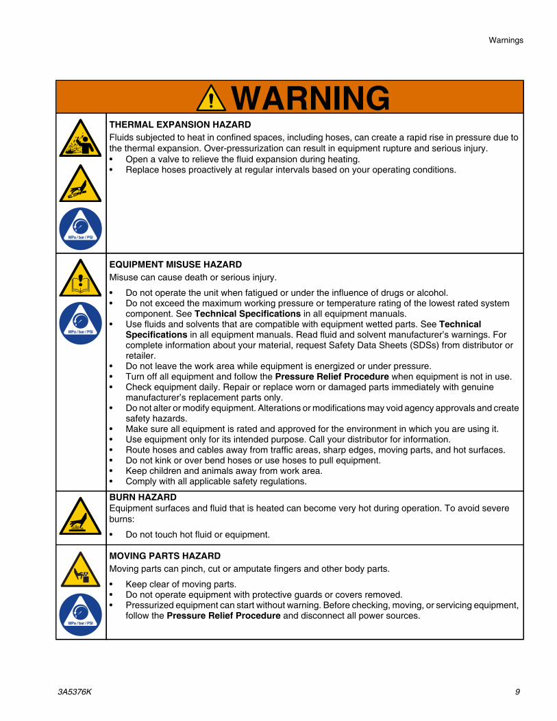
THERMAL EXPANSION HAZARDFluids subjected to heat in confined spaces, including hoses, can create a rapid rise in pressure due to the thermal expansion. Over-pressurization can result in equipment rupture and serious injury.• Open a valve to relieve the fluid expansion during heating.• Replace hoses proactively at regular intervals based on your operating conditions.
EQUIPMENT MISUSE HAZARDMisuse can cause death or serious injury.
• Do not operate the unit when fatigued or under the influence of drugs or alcohol.• Do not exceed the maximum working pressure or temperature rating of the lowest rated system
component. See Technical Specifications in all equipment manuals.• Use fluids and solvents that are compatible with equipment wetted parts. See Technical
Specifications in all equipment manuals. Read fluid and solvent manufacturer’s warnings. For complete information about your material, request Safety Data Sheets (SDSs) from distributor or retailer.
• Do not leave the work area while equipment is energized or under pressure.• Turn off all equipment and follow the Pressure Relief Procedure when equipment is not in use.• Check equipment daily. Repair or replace worn or damaged parts immediately with genuine
manufacturer’s replacement parts only.• Do not alter or modify equipment. Alterations or modifications may void agency approvals and create
safety hazards.• Make sure all equipment is rated and approved for the environment in which you are using it.• Use equipment only for its intended purpose. Call your distributor for information.• Route hoses and cables away from traffic areas, sharp edges, moving parts, and hot surfaces.• Do not kink or over bend hoses or use hoses to pull equipment.• Keep children and animals away from work area.• Comply with all applicable safety regulations.
BURN HAZARDEquipment surfaces and fluid that is heated can become very hot during operation. To avoid severe burns:
• Do not touch hot fluid or equipment.
MOVING PARTS HAZARDMoving parts can pinch, cut or amputate fingers and other body parts.
• Keep clear of moving parts.• Do not operate equipment with protective guards or covers removed.• Pressurized equipment can start without warning. Before checking, moving, or servicing equipment,
follow the Pressure Relief Procedure and disconnect all power sources.
WARNING

Warnings
10 3A5376K
PLASTIC PARTS CLEANING SOLVENT HAZARDMany cleaning solvents can degrade plastic parts and cause them to fail, which could cause serious injury or property damage.
• Use only compatible solvents to clean plastic structural or pressure-containing parts.• See Technical Specifications in all equipment manuals for materials of construction. Consult the
solvent manufacturer for information and recommendations about compatibility.
PRESSURIZED ALUMINUM PARTS HAZARDUse of fluids that are incompatible with aluminum in pressurized equipment can cause serious chemical reaction and equipment rupture. Failure to follow this warning can result in death, serious injury, or property damage.
• Do not use 1,1,1-trichloroethane, methylene chloride, other halogenated hydrocarbon solvents or fluids containing such solvents.
• Do not use chlorine bleach.• Many other fluids may contain chemicals that can react with aluminum. Contact your material
supplier for compatibility.
WARNING

Important Isocyanate (ISO) Information
3A5376K 11
Important Isocyanate (ISO) InformationIsocyanates (ISO) are catalysts used in two component materials.
Isocyanate Conditions
Spraying or dispensing fluids that contain isocyanates creates potentially harmful mists, vapors, and atomized particulates.
• Read and understand the fluid manufacturer’s warnings and Safety Data Sheets (SDSs) to know specific hazards and precautions related to isocyanates.
• Use of isocyanates involves potentially hazardous procedures. Do not spray with this equipment unless you are trained, qualified, and have read and understood the information in this manual and in the fluid manufacturer’s application instructions and SDSs.
• Use of incorrectly maintained or mis-adjusted equipment may result in improperly cured material, which could cause off gassing and offensive odors. Equipment must be carefully maintained and adjusted according to instructions in the manual.
• To prevent inhalation of isocyanate mists, vapors and atomized particulates, everyone in the work area must wear appropriate respiratory protection. Always wear a properly fitting respirator, which may include a supplied-air respirator. Ventilate the work area according to instructions in the fluid manufacturer’s SDSs.
• Avoid all skin contact with isocyanates. Everyone in the work area must wear chemically impermeable gloves, protective clothing and foot coverings as recommended by the fluid manufacturer and local regulatory authority. Follow all fluid manufacturer recommendations, including those regarding handling of contaminated clothing. After spraying, wash hands and face before eating or drinking.
• Hazard from exposure to isocyanates continues after spraying. Anyone without appropriate personal protective equipment must stay out of the work area during application and after application for the time period specified by the fluid manufacturer. Generally this time period is at least 24 hours.
• Warn others who may enter work area of hazard from exposure to isocyanates. Follow the recommendations of the fluid manufacturer and local regulatory authority. Posting a placard such as the following outside the work area is recommended:
TOXIC FUMESHAZARD
DO NOT ENTER DURINGSPRAY FOAM APPLICATIONOR FOR ___ HOURS AFTERAPPLICATION IS COMPLETE
DO NOT ENTER UNTIL:
DATE:TIME:
________________________

Important Isocyanate (ISO) Information
12 3A5376K
Material Self-ignition
Keep Components A and B SeparateNOTE: A-side material is isocyanate (ISO). B-side material is resin (RES).
Moisture Sensitivity of IsocyanatesExposure to moisture (such as humidity) will cause ISO to partially cure, forming small, hard, abrasive crystal that become suspended in the fluid. Eventually a film will form on the surface and the ISO will begin to gel, increasing in viscosity.
NOTE: The amount of film formation and rate of crystallization varies depending on the blend of ISO, the humidity, and the temperature.
Foam Resins with 245 fa Blowing AgentsSome foam blowing agents will froth at temperatures above 90°F (33°C) when not under pressure, especially if agitated. To reduce frothing, minimize preheating in a circulation system.
Changing Materials
Some materials may become self-igniting if applied too thick. Read material manufacturer’s warnings and material Safety Data Sheet (SDS).
Cross-contamination can result in cured material in fluid lines which could cause serious injury or damage equipment. To prevent cross-contamination:
• Never interchange component A and component B wetted parts.
• Never use solvent on one side if it has been contaminated from the other side.
NOTICE
Partially cured ISO will reduce performance and the life of all wetted parts.
• Always use a sealed container with a desiccant dryer in the vent, or a nitrogen atmosphere. Never store ISO in an open container.
• Keep the ISO pump wet cup or reservoir (if installed) filled with appropriate lubricant. The lubricant creates a barrier between the ISO and the atmosphere.
• Use only moisture-proof hoses compatible with ISO.• Never use reclaimed solvents, which may contain
moisture. Always keep solvent containers closed when not in use.
• Always lubricate threaded parts with an appropriate lubricant when reassembling.
NOTICE
Changing the material types used in your equipment requires special attention to avoid equipment damage and downtime.
• When changing materials, flush the equipment multiple times to ensure it is thoroughly clean.
• Always clean the fluid inlet strainers after flushing.• Check with your material manufacturer for chemical
compatibility.• When changing between epoxies and urethanes or
polyureas, disassemble and clean all fluid components and change hoses. Epoxies often have amines on the B (hardener) side. Polyureas often have amines on the B (resin) side.

Typical Installation
3A5376K 13
Typical Installation
Without circulation
*Shown exposed for clarity. Wrap with tape during operation.
FIG. 1: Typical Installation
B
G
F
G
D
E
(B-RES)
(A-ISO)
H
H
A
J
Ref. Description
A Gusmer Hydraulic ProportionerFTS Fluid Temperature Sensor (FTS)B Heated HoseD Heated Whip HoseE Spray GunF Fluid Inlets A and BG‡ Feed Pumps A and B
H Pressure Relief LinesJ‡ Air Supply Lines
† Included in some proportioner packages.
‡ Customer-supplied.
Ref. Description

Typical Installation
14 3A5376K
With proportioner manifold to drum circulation
*Shown exposed for clarity. Wrap with tape during operation.
FIG. 2: Typical Installation
(B-RES)
G
H
F
G
B
D
E
H
(A-ISO)
J
A
J
Ref. Description
A Gusmer Hydraulic ProportionerFTS Fluid Temperature Sensor (FTS)B† Heated HoseD† Heated Whip HoseE† Spray GunF Fluid Inlets A and B
G‡ Feed Pumps A and BH Pressure Relief LinesJ‡ Air Supply Lines
† Included in some proportioner packages.‡ Customer-supplied.
Ref. Description

Typical Installation
3A5376K 15
With gun manifold to drum circulation
*Shown exposed for clarity. Wrap with tape during operation.
FIG. 3: Typical Installation
(B-RES)
G
L
F
G
B
D
FTS*
K
L
(A-ISO)
J
H
H
A
Ref. Description
A Gusmer Hydraulic ProportionerFTS Fluid Temperature Sensor (FTS)B† Heated HoseD† Heated Whip HoseF Fluid Inlets A and BG‡ Feed Pumps A and BH Pressure Relief Lines
J Air Supply LinesK Gun Recirculation AdapterL Gun Recirculation Lines A and B
† Included in some proportioner packages.‡ Customer-supplied.
Ref. Description
Component Identification
16 3A5376K
Component Identification
*Shown exposed for clarity. Wrap with tape during operation.
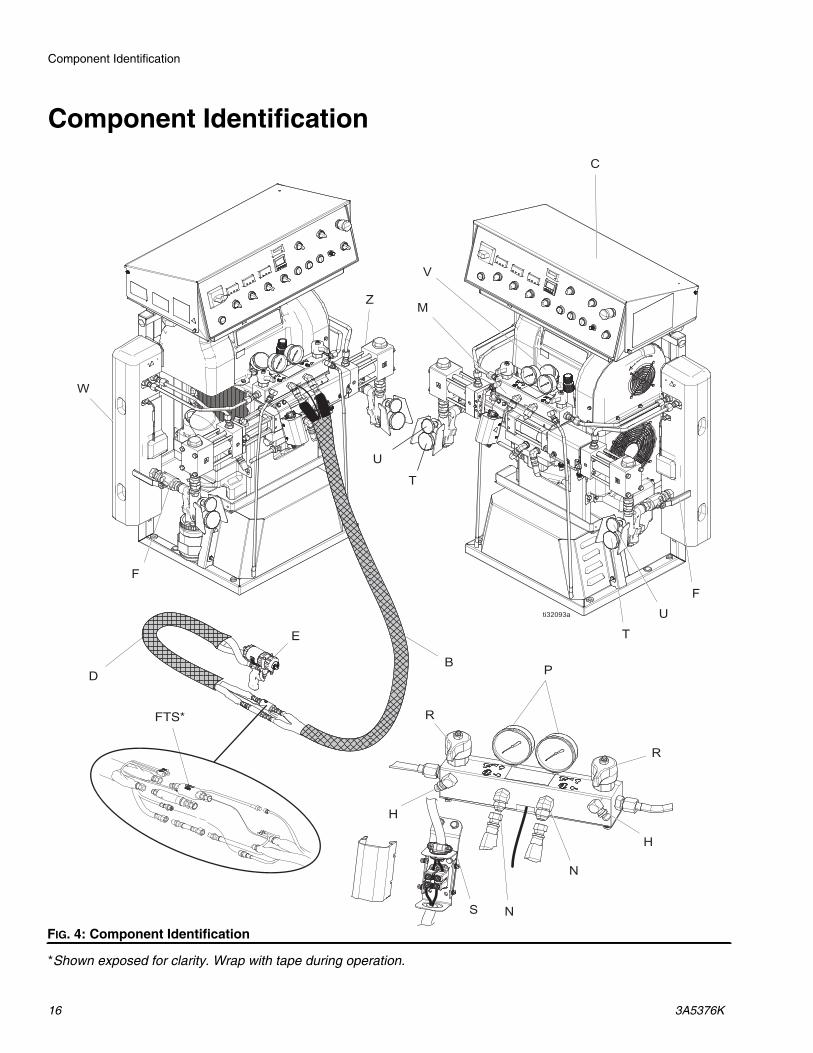
FIG. 4: Component Identification
B
FTS*
E
D

Component Identification
3A5376K 17
Ref. Description
B† Heated HoseC Electrical EnclosureD† Heated Whip HoseFTS Fluid Temperature Sensor (FTS)E† Spray GunF Fluid Inlet A and BH Pressure Relief Lines A and BM Proportioner ManifoldN Outlet A and BP Outlet Pressure Gauge A and B
R Pressure Relief Valve A and BS Electrical Junction BoxT Inlet Pressure Gauge A and BU Inlet Temperature Gauge A and BV Hydraulic Pressure GaugeW* Primary Heater A and BZ Fluid Pump A and B
* Located behind shroud.† Included in some proportioner packages.
Ref. Description

Component Identification
18 3A5376K
Control Panel
FIG. 5: Control Panel
0102
F
0102
F
0102
F
ti32106a
CE CACC CD CL CN CG
CFCR
CB CM CK CJ CH
CP
Ref. Description
CA Cycle CountdownCB Cycle Countdown Switch (ENABLE/DISABLE)CC Cycle CounterCD Cycle Counter Reset ButtonCE Main Power Disconnect (ON/OFF)CF Main Power Indicator LightCG Emergency Stop ButtonCH Control Power Switch (STOP/RUN/START)CJ Pressure Monitor Knob
CK* Pressure Monitor Indicator LightCL Pump Control Switch (PARK/NEUTRAL/PUMP)CM Pump Direction Indicator LightsCN Motor Power Switch (ON/OFF)CP Temperature Controllers A, B, and HoseCR Heat Zone Switches A, B, and Hose (ON/OFF)
* Red light indicates fault, white light indicates on.
Ref. Description

Component Identification
3A5376K 19

Installation
20 3A5376K
Installation
Mounting the System
NOTE: Wall mounting brackets are not included with the system. Evaluate the installation to determine if additional support is required beyond the floor mounting screws.
1. See Dimensions, page 106, for mounting hole specifications.
2. Use a minimum of 4 of the 6 mounting holes, evenly spaced in the base of the system frame, to secure base to the floor.
NOTE: Bolts are not included.
To prevent serious injury due to system tipping over, make sure the proportioner (A) is secured to the floor.
FIG. 6: Mount to the Floor

Setup
3A5376K 21
Setup
Grounding
Gusmer Hydraulic Proportioner: grounded through the power cord.
Spray gun: connect the grounded wire of the heated whip hose (D) to the fluid temperature sensor (FTS). See Install Fluid Temperature Sensor, page 24. Do not disconnect ground wire or spray without whip hose.
Fluid supply container: follow local code.
Object being sprayed: follow local code.
Solvent pails used when flushing: follow local code. Use only conductive metal pails, placed on a grounded surface. Do not place the pail on a non-conductive surface, such as paper or cardboard, which interrupts grounding continuity.
To maintain grounding continuity when flushing or relieving pressure: hold metal part of the spray gun (E) firmly to the side of a grounded metal pail, then trigger the gun.
General Equipment Guidelines
• Determine the correct size generator. Using the correct size generator and proper air compressor will enable the proportioner (A) to run at peak load. See Models, page 3. Ensure that the generator matches the voltage and phase of the proportioner.
Use the following procedure to determine the correct size generator.
1. List peak wattage requirements of all system components.
2. Add the wattage required by the system components.
3. Perform the following equation:
Total watts x 1.25 = kVA (kilovolt-amperes)
4. Select a generator size that is equal to or greater than the determined kVA.
• Use correctly sized power cords for the proportioner. Refer to the amperage listed in Models (page 3) to select the correct power cord.
• Use an air compressor with continuous run head unloading devices. Do not use direct online air compressors that start and stop during a job.
• Maintain and inspect the generator, air compressor, and other equipment per the manufacturer recommendations to avoid an unexpected shutdown.
The equipment must be grounded to reduce the risk of static sparking and electric shock. Electric or static sparking can cause fumes to ignite or explode. Improper grounding can cause electric shock. Grounding provides an escape wire for the electric current.
NOTICE
Failure to properly size the electric generator for equipment will cause voltage fluctuations that may result in equipment damage. To avoid damage to equipment, follow the guidelines listed below.
NOTICE
Voltage fluctuations can damage electrical equipment. To avoid voltage fluctuations, follow the guidelines listed below.

Setup
22 3A5376K
Connect Power
1. Select correctly sized power cord. Refer to the amperage listed in Models (page 3) to select the correct power cord.
2. Turn main power disconnect (CE) to OFF.
3. Open the electrical enclosure door (AH) by loosening the bolts (BH) and lifting the door upwards. See FIG. 8.
4. Route power cable through power inlet cord grip (AL) in electrical enclosure (C). Tighten cord grip (AL). See FIG. 8.
5. Connect incoming power wires to main disconnect terminals (AJ) and main ground lug (AK) as shown in FIG. 8. Torque to 55 in-lbs (6.2 N•m). Gently pull on all connections to verify they are properly secured.
a. 230 V, 1 phase: Using 5/32 or 4 mm hex allen wrench, connect two power leads to L1 and L2. Connect green to ground lug (AK).
b. 230 V, 3 phase: Using 5/32 or 4 mm hex allen wrench, connect three power leads to L1, L2, and L3. Connect green to ground lug (AK).
c. 400 V, 3 phase: Using 5/32 or 4 mm hex allen wrench, connect three power leads to L1, L2, and L3. Connect neutral to N. Connect green to ground lug (AK).
6. Verify all items are connected properly as shown in FIG. 8. Close the electrical enclosure door (AH) and tighten the bolts (BH).
7. Verify electric motor fan (BK) rotation is correct.
a. Turn the main power disconnect (CE) to ON.
b. Turn the control power switch (CH) to START. Verify the pump control switch (CL) is in NEUTRAL.
c. Briefly turn the motor power switch (CN) to ON. Observe the direction the electric motor fan (BK) rotates. See FIG. 7.
8. If the motor fan rotation is not correct:
a. Immediately turn the motor power switch (CN) to OFF.
b. Turn the control power switch (CH) to STOP.
c. Turn the main power disconnect (CE) to OFF.
d. Repeat Connect Power. Swap the incoming power wires between L1 and L2.
DANGER
SEVERE ELECTRIC SHOCK HAZARDThis equipment can be powered by more than 240 V. Contact with this voltage will cause death or serious injury.
• Turn off and disconnect power at main switch before disconnecting any cables and before servicing equipment.
• This equipment must be grounded. Connect only to grounded power source.
• All electrical wiring must be done by a qualified electrician and comply with all local codes and regulations.
NOTICE
350-415 VAC Gusmer Hydraulic Proportioners are not designed to operate from a 480 VAC power source. To avoid damage to equipment, follow the guidelines listed below.
FIG. 7: Electric Motor Rotation
BK
BH AH

Setup
3A5376K 23
NOTE: See Models, page 3, to identify which wiring combination is used with your Gusmer model.
FIG. 8: Connect Incoming Power Wires
ti320
99bT1 T2 T3 N
L1 L2 L3 N
T1 T2 T3 N
L1 L2 L3 N
T1 T2 T3 N
L1 L2 L3 N
AJ
AK
AL
AH

Setup
24 3A5376K
TSL Pump Lubrication System SetupComponent A (ISO) Pump: Fill TSL reservoir (AM) with Graco TSL (Throat Seal Liquid), part 206995 (supplied).
1. Lift the TSL lubricant reservoir (AM) out of the reservoir bracket (AN) and remove the cap.
2. Fill with fresh Graco TSL. Thread the TSL reservoir (AM) onto the cap and place it in the reservoir bracket (AN).
3. Push the TSL inlet filter (AP) approximately 1/3 of the way into the reservoir.
4. Push the TSL outlet tube (AR) into the reservoir until it reaches the bottom.
NOTE: The TSL outlet tube (AR) must reach the bottom of the reservoir to ensure that isocyanate crystals will settle to the bottom and not be siphoned into the TSL inlet filter (AP). No priming is required.
Install Fluid Temperature SensorThe fluid temperature sensor (FTS) is supplied. Install the FTS between the heated hose (B) and the heated whip hose (D). Refer to your heated hose manual for instructions. Add any additional sections of heated hose if desired. Be sure cables have slack when hose bends. Wrap cable and electrical connections with electrical tape.
FIG. 9

Setup
3A5376K 25
Install Heated Hose to Proportioner
1. Turn main power disconnect (CE) to OFF.
NOTE: The Gusmer Hydraulic Proportioner (A) is only compatible with standard, two-component heated hoses using a thermocouple. See heated hose manual for detailed instructions on connecting heated hoses.
NOTE: The fluid temperature sensor (FTS) and heated whip hose (D) must be used with the heated hose (B). Hose length, including heated whip hose (D), must be at least 60 ft (18.3 m) minimum.
2. Connect heated hose to proportioner.
a. Connect fluid hoses to proportioner fluid manifold.
NOTE: Fluid outlets (N) come with adapter fittings to allow use of 1/4 in. and 3/8 in. ID fluid hoses. To use 1/2 in. (13 mm) ID fluid hoses, remove adapters.
b. Remove box cover (BL) and loosen lower strain relief (AT). Connect hose power wires to terminal block (AS). A and B hose wire positions are not important. Torque to 35-50 in-lb (4.0-5.6 N•m).
c. Fully tighten lower strain relief (AT) screws and replace cover.
d. Connect FTS cable connectors (AV).
3. Close both needle valves (AB) on gun manifold (AA).
4. Connect heated whip hose (D) to gun manifold (AA). Do not connect manifold to gun.
FIG. 10: Heated Hose Electrical Junction Box
BLAT
AS
AV
FIG. 11: Gun Manifold
FIG. 12
AA
AB
AA
D

Setup
26 3A5376K
Adjust Hose Transformer Wiring
NOTE: The fluid temperature sensor (FTS) and heated whip hose (D) must be used with the heated hose. Hose length, including whip hose, must be at least 60 ft (18.3 m) minimum. GH-2 proportioners can be used with a maximum of 310 ft (94.5 m) of hose. GH-4 proportioners can be used with a maximum of 410 ft (125.0 m) of hose.
1. Verify that power is disconnected.
2. Remove the transformer cover. See FIG. 13.
3. Move the wire on the hose transformer (AC) to the terminal that matches the length of hose installed. Wire is factory-set to 60 ft. See FIG. 14.
NOTE: The transformer terminals are labeled with the corresponding total length of hose, including the whip hose. Always use a whip hose and select the transformer tap that matches the total hose length. If using a whip hose longer than 10 ft (3.0 m), round the total length of hose down to determine the correct terminal setting.
4. Reinstall the transformer cover. See FIG. 13.
FIG. 13: Hose Transformer Cover
AC
NOTICE
The maximum amount of heat generated by the heated hose depends on the input voltage to the proportioner. If possible, adjust the generator voltage within the marked voltage range. This will increase or decrease the maximum current (and heat) available to the hose. To avoid damage to the proportioner and hose, do not exceed the maximum voltage rating of the system. Do not exceed a hose current of 50 A.
FIG. 14: Hose Transformer Wiring
310
260
210
160
110
60

Setup
3A5376K 27
Flush Before Using EquipmentThe equipment was tested with lightweight oil, which is left in the fluid passages to protect parts. To avoid contaminating your fluid with oil, flush the equipment with a compatible solvent before using the equipment. See Flushing, page 42.
Connect Feed Pumps 1. Install feed pumps (G) in component A and B supply
drums. See Typical Installation, page 13.
NOTE: A minimum feed pressure of 50 psi (0.35 MPa, 3.5 bar) is required at both inlet pressure gauges (T). Maximum feed pressure is 250 psi (1.75 MPa, 17.5 bar). Maintain A and B feed pressures within 10% of each other.
2. Seal component A drum. If used, install desiccant dryer in drum vent. Desiccant dryer sold separately.
3. Install agitator in component B drum, if necessary. Agitator sold separately.
4. Ensure A and B inlet valves (AD) are closed.
NOTE: Fluid inlet (F) hoses from feed pumps (G) should be 3/4 in. (19 mm) ID.
FIG. 15: Inlet Pressure Gauge on Inlet Assembly
FIG. 16: Inlet Valve on Inlet Assembly
T
AD

Startup
28 3A5376K
Startup
1. Verify that all Setup steps are complete. See page 21.
2. Check that the fluid inlet filter (AE) is clean before daily startup.
3. Check TSL reservoir (AM). Check level and condition of lubrication daily. See TSL Pump Lubrication System, page 45.
4. Measure the material level in each drum. A and B drum level sticks (24M174) sold separately.
5. Check hydraulic fluid level. Hydraulic reservoir is filled at the factory. Check fluid level before operating the first time, and weekly thereafter. See Maintenance, page 43.
6. If using a generator:
a. Check generator fuel level.
b. Confirm main power disconnect (CE) is OFF before starting generator.
c. Ensure the main breaker on the generator is in the off position.
d. Start the generator. Allow it to reach full operating temperature.
7. Switch on the air compressor, air dryer, and breathing air, if equipped.
To prevent serious injury, only operate the proportioner with all covers and shrouds in place.
NOTICE
Proper system setup, startup, and shutdown procedures are critical to electrical equipment reliability. The following procedures ensure steady voltage. Failure to follow these procedures will cause voltage fluctuations that can damage electrical equipment and void the warranty.
FIG. 17: Fluid Inlet Filters
AE
AM
NOTICE
Running out of fuel will cause voltage fluctuations that can damage equipment and void the warranty. Do not run out of fuel.
FIG. 18: Main Power Disconnect
FIG. 19

Startup
3A5376K 29
8. For first startup of new system, load fluid with feed pumps (G). See Component Identification, page 16.
a. Turn on agitator, if equipped.
b. Turn both pressure relief valves (R) to SPRAY
.
c. Turn on feed pumps (G).
d. Open inlet valves (AD). Check for leaks.
e. Hold gun manifold (AA) over two grounded waste containers. Open needle valves (AB) A and B until clean, air-free fluid comes from valves. Close valves.
FIG. 20
FIG. 21
R
AD
Cross contamination can result in cured material in fluid lines which could cause injury from splashing or damage equipment. To prevent cross-contamination:
• Never interchange component A and component B wetted parts.
• Never use solvent on one side if it has been contaminated from the other side.
• Always provide two waste containers to keep component A and component B fluids separate.
FIG. 22
AB
AA

Startup
30 3A5376K
9. Turn the motor power switch (CN) OFF and turn the pump control switch (CL) to NEUTRAL.
10. Set temperature controllers (CP). See Digital Temperature Controllers, page 31.
11. Preheat the system:
a. If you need to circulate fluid through the system to preheat the drum supply, see Connect Proportioner Manifold to Drum Circulation, page 33. If you need to circulate material through the heated hose to the gun manifold, see Connect Gun Manifold to Drum Circulation, page 34.
b. Turn hose heat zone switch on.
c. Wait for the hose to reach set point temperature.
NOTE: Hose heat-up time may increase at voltages less than nominal 230 VAC when maximum hose length is used. Hose transformer wiring must match hose length (see Adjust Hose Transformer Wiring, page 26).
d. Turn on A and B heat zones by turning on heat zone switches (CR). Wait until the heat zone actual temperatures reach the temperature setpoints.
12. If desired, Set Cycle Countdown, page 32.
13. The proportioner is ready for operation. See Spraying, page 36.
FIG. 23
This equipment is used with heated fluid which can cause equipment surfaces to become very hot. To avoid severe burns:
• Do not touch hot fluid or equipment.• Do not turn on hose heat without fluid in hoses.• Allow equipment to cool completely before
touching it.• Wear gloves if fluid temperature exceeds 110° F
(43° C).
Thermal expansion can cause over-pressurization, resulting in equipment rupture and serious injury, including fluid injection. Do not pressurize system when preheating hose.
0102
F
0102
F
0102
F
ti32106a
CL CN
FIG. 24: Heat Zone Switch for Hose
FIG. 25
0102
F
0102
F
0102
F
ti32106a
Hose Heat Zone Switch
0102
F
0102
F
0102
F
ti32106a
A and B Heat Zone Switches

Startup
3A5376K 31
Digital Temperature ControllersTemperature controls are factory-programmed. The only user-programmable parameters are temperature setpoint “SP1” and temperature units “uniT” (°C or °F).
The proportioner has three temperature controllers (CP) that automatically manage the temperature for the A and B primary heaters (W) and the heated hose (B).
Adjust Temperature Set Point
1. Turn off all heat zone switches (CR) and motor power switch (CN).
2. Set pump control switch (CL) to neutral.
3. Ensure the main power disconnect (CE) is ON. Main power indicator light (CF) will illuminate.
4. Start machine by turning control power switch (CH) to START. Light in switch and temperature controllers (CP) will illuminate.
NOTE: Wait five seconds. Initial information displayed during startup does not affect hose performance.
5. Press (SCROLL).
6. When module screen displays “SPI,” use and
(UP, DOWN) to select desired set point.
7. Once desired set point is reached, press both
and (UP, DOWN) at the same time to return to actual temperature display. Hose is now controlling temperature to desired set point.
NOTE: Temperature controllers (CP) normally display actual temperature. When illuminated, the red “O1” on the temperature controller indicates that controller is on and actively trying to heat the heater to match the temperature set point. The heat zone switch must be in the ON position for the heater relay (605) to receive a signal from the controller and cause the temperature to increase. The “O1” disappears when controller is OFF and not actively heating. The “O1” cycles on and off to indicate temperature maintenance.
Thermal expansion can cause over-pressurization, resulting in equipment rupture and serious injury, including fluid injection. Do not pressurize system when preheating hose.
To avoid fire and explosion, use only Graco-supplied, pre-programmed temperature controllers (CP). If you encounter a problem with a temperature controller, order a replacement.
NOTICE
Heated hoses and primary heaters must always contain fluid when hose power is on. Never turn on heat zone switches while a heated hose or primary heater is empty. Powering empty hoses and heaters may cause equipment damage.
NOTICE
Always completely unroll and bleed the air from the hose before each use. If the air is not bled from the hose, heat transfer from the heating conductor will not be uniform. In the worst case, the conductor can be damaged. The warranty is void in such cases.
FIG. 26: Temperature Controller
O1O2
F

Startup
32 3A5376K
Change Between Fahrenheit and Celsius
The temperature controllers (CP) are factory-set to display Fahrenheit units.
1. Enter the setup menu by pressing (SCROLL). “SP1” is shown on the display.
2. Press (SCROLL) repeatedly until “LOCK” is shown on the display.
3. Press (UP) or (DOWN) arrow until “nonE” is shown on the display.
4. Press (SCROLL) again until “UNIT” is shown on the display.
5. Press (UP) or (DOWN) arrow buttons until the desired unit of °C or °F is shown on the display.
6. Press (SCROLL) to return to the setup menu. “UNIT” will be shown on the display again.
7. Press (SCROLL) repeatedly until “LOCK” is shown on the display again.
8. Press (UP) or (DOWN) arrow buttons until “uSEr” is shown on the display.
9. Press (SCROLL) to return to the setup menu. “LOCK” will be shown on the display again.
10. Return to the actual temperature display and normal
operation by pressing (UP) and (DOWN) buttons at the same time.
Set Cycle Countdown1. Turn the pump control switch (CL) to NEUTRAL.
2. Turn the motor power switch (CN) to OFF.
3. Turn the main power disconnect (CE) to ON. Then turn the control power switch (CH) to ON.
4. Enable cycle countdown by turning the cycle countdown switch (CB) to ON. When cycle countdown is enabled, the pump shuts off automatically after a set number of cycles.
5. Change the preset cycle countdown value to the number of cycles for the pump to complete before automatically shutting off. See table for approximate cycles by volume.
Table 1: Nominal Volume/Cycle
a. Press the digit key associated with the number you would like to change.
b. Press the reset key or wait 3 seconds to accept the new value. When new value has been accepted, the cycle countdown is set.
NOTE: To reset the counter to the preset value, press the reset key again.
Pump Size Cycles by Volume
140 (GH-2)13.5 cycles/gal
3.6 cycles/L
120 (GH-4)15.9 cycles/gal
4.2 cycles/L
FIG. 27: Cycle Countdown
PR 1Reset Key Mode
Key
Digit Keys

Fluid Circulation
3A5376K 33
Fluid Circulation
NOTE: Optimum heat transfer is achieved at lower fluid flow rates with temperature set points at desired drum temperature.
Connect Proportioner Manifold to Drum CirculationTo circulate through gun manifold (AA) and preheat hose, see Connect Gun Manifold to Drum Circulation, page 34.
1. Follow Pressure Relief Procedure, page 41.
2. Install A-side and B-side pressure relief lines (H) back to component A and B supply drums. See Typical Installation With proportioner manifold to drum circulation, page 14.
NOTE: Use hoses rated for the maximum working pressure of this equipment. See Technical Specifications, page 108.
3. Set pressure relief valves (R) to PRESSURE
RELIEF/CIRCULATION .
4. Follow Reduce Hydraulic Pressure, page 35.
To avoid injection injury and splashing, do not install shutoffs downstream of the pressure relief valves (R). The valves function as overpressure relief valves
when set to SPRAY .
Pressure relief lines (H) and gun recirculation lines (L) must be rated for the maximum working pressure of the proportioner. See Technical Specifications, page 108. Pressure relief lines must be open so valves can automatically relieve pressure when machine is operating.
NOTICE
To prevent equipment damage, do not circulate fluid containing a blowing agent without consulting with your material supplier regarding fluid temperature limits.
FIG. 28
R

Fluid Circulation
34 3A5376K
Connect Gun Manifold to Drum CirculationNOTE: The Fusion gun manifold is shown.
Circulating fluid through the gun manifold (AA) allows rapid preheating of the heated hose (B).
1. Follow Pressure Relief Procedure, page 41.
2. Install gun manifold (AA) on gun recirculation adapter (K). Connect gun recirculation lines (L) to gun recirculation adapter (K).
NOTE: Use hoses rated for the maximum working pressure of this equipment. See Technical Specifications, page 108.
3. Route gun recirculation lines (L) back to respective component A or B supply drum.
4. Set pressure relief valves (R) to SPRAY.
5. Follow Reduce Hydraulic Pressure, page 35.
FIG. 29: Gun Recirculation Adapter Installation
AA
K
L
Gun Recirculation
Adapter (K) Kit GunManual in English
246362 Fusion AP 309818256566 Fusion CS 313058
FIG. 30
R

Fluid Circulation
3A5376K 35
Reduce Hydraulic Pressure1. Turn pump control switch (CL) to NEUTRAL
position and verify motor power switch (CN) is OFF. Turn main power disconnect (CE) ON. Then start machine by turning control power switch (CH) to START.
2. Before starting the hydraulic motor, unlock the hydraulic pressure adjuster (AG) by rotating the lower adjuster knob counter-clockwise. Then rotate the upper adjuster knob counter-clockwise until it ceases to move to set at lowest possible pressure. The hydraulic pressure adjuster can be relocked by turning the lower adjuster knob clockwise.
3. Verify cycle countdown switch (CB) is set to OFF.
4. Turn motor power switch (CN) to ON. Then turn pump control switch (CL) to PUMP. Circulate fluid at lowest possible pressure.
5. If preheating system:
a. Verify temperature targets. See Digital Temperature Controllers, page 31.
b. Turn on all 3 heat zone switches (CR).
c. Wait until the inlet temperature gauges (U) reach the minimum chemical temperature from the supply drums. Turn pump control switch (CL) to NEUTRAL. Then turn the motor power switch (CN) to OFF.
6. Return to step 12 of Startup, page 28.
FIG. 31: Hydraulic Pressure Adjustment
FIG. 32
AG
0102
F
0102
F
0102
F
ti32106a
CL CNCE
CH
FIG. 33
FIG. 34: Inlet Pressure Gauge on Inlet Assembly
0102
F
0102
F
0102
F
ti32106a
c38
CN
CHCR
CL
U

Spraying
36 3A5376K
Spraying
1. Follow Startup, page 28.
2. Turn pump control switch (CL) to NEUTRAL. Turn motor power switch (CN) to OFF.
3. Engage gun piston safety lock and close gun fluid inlet valves A and B.
4. Attach gun manifold (AA). Connect gun air line. Open air line valve.
NOTE: The Fusion AP gun is shown.
5. Adjust the gun air pressure. Do not exceed 130 psi (0.2 MPa, 2 bar).
6. Set pressure relief valves (R) to SPRAY
.
7. Verify heat zone switches (CR) are on and temperatures are on target. See Digital Temperature Controllers, page 31, to read and operate temperature controllers (CP).
8. Verify inlet valves (AD) on both fluid pumps (Z) are open.
9. Turn pressure monitor knob (CJ) to OFF. See FIG. 39.
FIG. 35
FIG. 36: Attach Gun Manifold
AA
FIG. 37
FIG. 38: Inlet Valve Assembly
R
AD

Spraying
3A5376K 37
10. Start hydraulic motor by turning on motor power switch (CN). Then turn pump control switch (CL) to PUMP.
11. Set hydraulic pressure adjuster (AG) to desired fluid stall pressure. Turn adjuster clockwise to increase pressure and counter-clockwise to decrease pressure. Use hydraulic pressure gauge (V) to view hydraulic pressure.
NOTE: Component A and B fluid outlet pressures will be higher than the hydraulic set pressure. See Technical Specifications, page 108, for the oil pressure ratio of your model. Component A and B fluid outlet pressures may be viewed on the outlet pressure gauges (P). Once desired fluid stall pressure is set, lock the adjuster (AG) in place by rotating lower portion clockwise until tight.
NOTE: If not installed with proportioner manifold recirculation, ensure pressure relief lines (H) have been routed to a suitable waste container to catch excess fluid.
12. Check fluid outlet pressure gauges (P) to ensure proper pressure balance. If imbalanced, reduce pressure of higher component by slightly turning pressure relief valve (R) for that component toward
PRESSURE RELIEF/CIRCULATION until
gauges show balanced pressures.
13. If desired, set pressure monitor. Turn pressure monitor knob (CJ) to desired setting.
NOTE: This will automatically shut down the proportioner (A) if the pressure imbalance setting is exceeded.
FIG. 39
FIG. 40
0102
F
0102
F
0102
F
ti32106a
CL CN
CJ
VP
AG
FIG. 41
FIG. 42
R
P
0102
F
0102
F
0102
F
ti32106a
CJ
Spraying
38 3A5376K
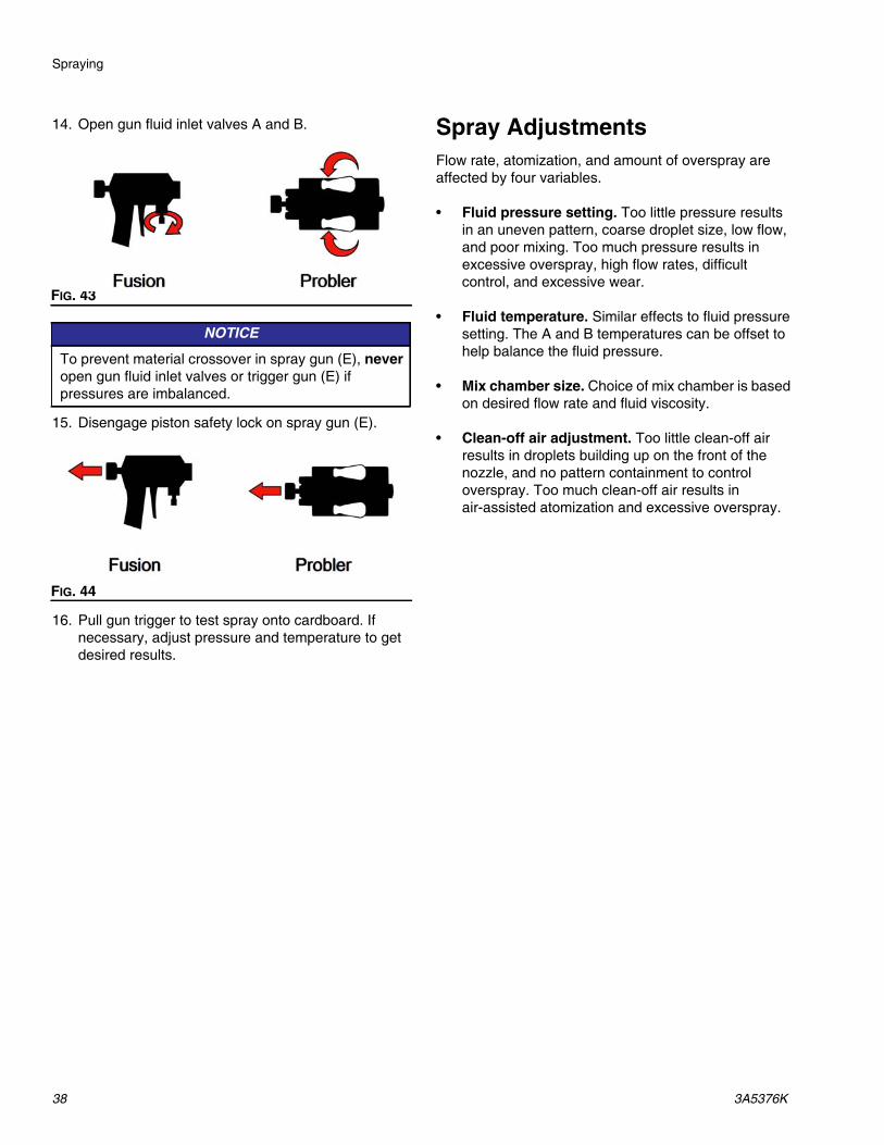
14. Open gun fluid inlet valves A and B.
15. Disengage piston safety lock on spray gun (E).
16. Pull gun trigger to test spray onto cardboard. If necessary, adjust pressure and temperature to get desired results.
Spray AdjustmentsFlow rate, atomization, and amount of overspray are affected by four variables.
• Fluid pressure setting. Too little pressure results in an uneven pattern, coarse droplet size, low flow, and poor mixing. Too much pressure results in excessive overspray, high flow rates, difficult control, and excessive wear.
• Fluid temperature. Similar effects to fluid pressure setting. The A and B temperatures can be offset to help balance the fluid pressure.
• Mix chamber size. Choice of mix chamber is based on desired flow rate and fluid viscosity.
• Clean-off air adjustment. Too little clean-off air results in droplets building up on the front of the nozzle, and no pattern containment to control overspray. Too much clean-off air results in air-assisted atomization and excessive overspray.
FIG. 43
NOTICE
To prevent material crossover in spray gun (E), never open gun fluid inlet valves or trigger gun (E) if pressures are imbalanced.
FIG. 44

Standby
3A5376K 39
Standby
If you stop spraying for a period of time, either:
• Shutdown unit (page 39) and follow Pressure Relief Procedure (page 41).
• Or recirculate at low pressures. See Fluid Circulation, page 33.
Shutdown
1. Turn pressure monitor knob (CJ) to OFF.
2. Turn pump control switch (CL) to PARK. Trigger the gun or relieve pressure using the pressure relief valves (R) on the proportioner manifold (M).
3. Turn motor power switch (CN) to OFF when the pump is in the leftmost position.
4. Turn all heat zone switches (CR) to OFF.
5. Turn main power disconnect (CE) to OFF. The main power indicator light (CF) will turn off.
6. Turn off the air compressor, air dryer, and breathing air, if equipped.
7. Turn off feed pumps (G).
NOTICE
Proper system setup, startup, and shutdown procedures are critical to electrical equipment reliability. The following procedures ensure steady voltage. Failure to follow these procedures will cause voltage fluctuations that can damage electrical equipment and void the warranty.
FIG. 45
0102
F
0102
F
0102
F
ti32106a
CL CN
CR
CE
CF CJ

Shutdown
40 3A5376K
8. Close both fluid inlet valves (AD). 9. Relieve any remaining pressure. Follow Pressure Relief Procedure, starting with step 2, page 41.
FIG. 46: Fluid Inlet Assembly
AD

Pressure Relief Procedure
3A5376K 41
Pressure Relief ProcedureFollow the Pressure Relief Procedure whenever you see this symbol.
1. Follow Shutdown, page 39.
2. Relieve pressure in spray gun (E) and perform gun shutdown procedure. See your gun manual.
3. Verify gun piston safety lock is engaged.
4. Close gun fluid inlet valves A and B.
5. Shut off feed pumps (G) and drum agitator, if used.
6. Route pressure relief lines (H) to waste containers or back to supply drums. Turn pressure relief valves
(R) to PRESSURE RELIEF/CIRCULATION .
Ensure both fluid outlet pressure gauges (P) drop to 0.
7. Set pressure relief valves (R) to SPRAY on proportioner manifold (M) to seal out moisture.
8. Disconnect gun air hose and remove gun manifold (AA).
This equipment stays pressurized until pressure is manually relieved. To help prevent serious injury from pressurized fluid, such as skin injection, splashing fluid and moving parts, follow the Pressure Relief Procedure when you stop spraying and before cleaning, checking, or servicing the equipment.
FIG. 47
FIG. 48
FIG. 49
FIG. 50
R
P
AA
Flushing
42 3A5376K
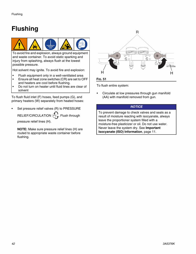
Flushing
To flush fluid inlet (F) hoses, feed pumps (G), and primary heaters (W) separately from heated hoses:
• Set pressure relief valves (R) to PRESSURE
RELIEF/CIRCULATION . Flush through
pressure relief lines (H).
NOTE: Make sure pressure relief lines (H) are routed to appropriate waste container before flushing.
To flush entire system:
• Circulate at low pressures through gun manifold (AA) with manifold removed from gun.
To avoid fire and explosion, always ground equipment and waste container. To avoid static sparking and injury from splashing, always flush at the lowest possible pressure.
Hot solvent may ignite. To avoid fire and explosion:
• Flush equipment only in a well-ventilated area• Ensure all heat zone switches (CR) are set to OFF
and heaters are cool before flushing.• Do not turn on heater until fluid lines are clear of
solvent
FIG. 51
NOTICE
To prevent damage to check valves and seals as a result of moisture reacting with isocyanate, always leave the proportioner system filled with a moisture-free plasticizer or oil. Do not use water. Never leave the system dry. See Important Isocyanate (ISO) Information, page 11.
R
H H

Maintenance
3A5376K 43
Maintenance
Prior to performing any maintenance procedures, follow Pressure Relief Procedure, page 41.
Preventative Maintenance ScheduleThe operating conditions of your particular system determine how often maintenance is required. Establish a preventative maintenance schedule by recording when and what kind of maintenance is needed, and then determine a regular schedule for checking your system.
• Inspect hydraulic and fluid lines for leaks daily.
• Clean up all hydraulic leaks; identify and repair the cause of the leak.
• Inspect both fluid inlet filters (AE) daily. See Clean Fluid Inlet Filters, page 44.
• Keep component A from exposure to moisture to prevent crystallization.
• Check hydraulic fluid level weekly. Check hydraulic fluid level on the dipstick (BN). Fluid level must be between indent marks on dipstick. Refill as required with approved hydraulic fluid, see Change Hydraulic Fluid and Filter (page 61) and the Approved Anti-Wear (AW) Hydraulic Oils Table (page 62). If hydraulic fluid is dark in color, change fluid and filter.
- Change break-in oil in a new unit until after the first 250 hours of operation or within 3 months, whichever comes first. See Table 2: Frequency of Oil Changes for recommended frequency of oil changes.
Table 2: Frequency of Oil Changes
Proportioner Maintenance
Fluid Inlet Filters
• Inspect fluid inlet filters daily, see Clean Fluid Inlet Filters, page 44.
Grease Pressure Relief Valves
• Grease pressure relief valves (R) with Graco Fusion grease (117773) weekly. Grease sold separately.
TSL Lubrication Level
Inspect TSL lubricant level and condition daily. Refill or replace as needed. See TSL Pump Lubrication System, page 45.
FIG. 52
BN
Ambient TemperatureRecommended
Frequency
0° to 90° F (-17° to 32° C)
1000 hours or 12 months, whichever comes first
90° F and above (32° C and above)
500 hours or 6 months, whichever comes first
FIG. 53

Maintenance
44 3A5376K
Moisture
To prevent crystallization, do not expose component A to moisture in air.
Gun Mix Chamber Ports
Clean mix chamber ports on gun (E) regularly. See gun manual.
Gun Check Valve Filters
Clean gun check valve filters regularly. See gun manual.
Dust Protection
Use clean, dry, oil-free compressed air to prevent dust buildup on control modules, fans, and electric motor fan.
Vent Holes
Keep vent holes on proportioner shrouds, electrical enclosure (C), and hose transformer (128) cover open.
Clean Fluid Inlet Filters
The fluid inlet filters (AE) remove particles that can plug the pump and valves. Inspect the filters daily as part of the startup routine and clean as required.
Isocyanate can crystallize from moisture contamination or from freezing. If the chemicals used are clean and the proper storage, transfer, and operating procedures are followed, there should be minimal contamination of the component A filter.
NOTE: Clean the component A filter only during daily startup. This minimizes moisture contamination by immediately flushing out any isocyanate residue at the start of dispensing operations.
1. Close the fluid inlet valve (AD). Then shut off the appropriate feed pump (G). This prevents material from being pumped while cleaning the fluid inlet filter (AE).
2. Place a container under the filter base (AW) to catch drain-off when removing the filter plug (AY).
3. Remove the fluid inlet filter (AE) from the housing. Thoroughly flush the filter with compatible solvent and shake it dry. Inspect the filter. No more than 25% of the filter should be restricted. If more than 25% of the filter is blocked, replace the screen. Inspect the filter gasket (AZ) and replace as required.
4. Ensure the filter plug (AY) is screwed into the filter base (AW).
5. Open the fluid inlet valve (AD), ensure that there are no leaks.
NOTICE
Do not over-tighten the filter plug (AY). Over-tightening can cause damage to filter plug threads. Let the o-ring make the seal.
FIG. 54: Inlet Filter Assembly
AD

Maintenance
3A5376K 45
TSL Pump Lubrication SystemCheck the condition of the TSL lubricant daily. Change the lubricant if it becomes a gel, its colors darkens, or it becomes diluted with isocyanate.
Gel formation is due to moisture absorption by the TSL lubricant. The interval between changes depends on the environment in which the equipment is operating. The TSL lubrication system minimizes exposure to moisture, but some contamination is still possible.
TSL lubricant discoloration is due to continual seepage of small amounts of isocyanate past the pump seals during operation. If the seals are operating properly, TSL lubricant replacement due to discoloration should not be necessary more often than every 3 or 4 weeks.
To change TSL lubricant:
1. Lift the TSL reservoir (AM) out of the reservoir bracket (AN) and remove the cap. While holding the cap over a suitable waste container, remove the TSL inlet filter (AP) and allow the TSL to drain.
NOTE: TSL inlet filter (AP) contains a check valve inside. The check valve also must be flushed clean.
2. Drain the TSL reservoir (AM) and flush it with clean lubricant.
3. When the reservoir is flushed clean, fill with fresh lubricant.
4. Thread the TSL reservoir (AM) onto the cap and place it in the reservoir bracket (AN).
5. Push the TSL inlet filter (AP) tube approximately 1/3 of the way into the TSL reservoir.
6. Push the TSL outlet tube (AR) into the reservoir until it reaches the bottom.
NOTE: The TSL outlet tube (AR) must reach the bottom of the TSL reservoir to ensure that isocyanate crystals will settle to the bottom and not be siphoned into the TSL inlet filter (AP).
NOTE: No priming is required.
FIG. 55: Pump Lubrication System

Troubleshooting
46 3A5376K
Troubleshooting1. Follow Pressure Relief Procedure, page 41,
before checking or repairing proportioner.
2. Turn main power OFF.
3. Allow equipment to cool.
NOTE: To avoid unnecessary repairs, try the recommended solutions in the order given for each problem. Before assuming there is a problem, determine that wiring is correct and all circuit breakers, switches, and control are properly set.
Online TroubleshootingTo quickly view online help for troubleshooting, scan the QR code with your smartphone or visit help.graco.com.
Hydraulic Drive System
DANGER
SEVERE ELECTRIC SHOCK HAZARDThis equipment can be powered by more than 240 V. Contact with this voltage will cause death or serious injury.
• Turn off and disconnect power at main switch before disconnecting any cables and before servicing equipment.
• All electrical wiring must be done by a qualified electrician and comply with all local codes and regulations.
Problem Cause Solution
Electric motor will not start or electric motor stops during operation.
Motor or wiring circuit issue Check the position of the relay (RLY2). If the relay is in the down position, check the motor. If the relay is in the up position, check wiring.
Loose connections and/or relay (RLY2) is not activating
Check wiring between the following components:
• motor junction box and RLY2• check fuses F1 and F2• RLY2 and motor switch (SW7)
Motor circuit breaker tripped Confirm wiring is correct and insulation is intact. Reset CB4 within the electrical enclosure.

Troubleshooting
3A5376K 47
Hydraulic pump develops low or no pressure. Pump makes screeching noise.
Pump is not primed or lost its prime Motor (43) must operate counterclockwise from pulley end. Adjust motor wiring according to schematic found inside motor electrical junction box.
Check dipstick (118) to ensure that hydraulic reservoir is properly filled. See Preventative Maintenance Schedule, page 43.
Check that inlet fittings (33, 34, 35, 39) are fully tight to ensure no air is leaking into the pump inlet.
To prime hydraulic pump (27), run unit at lowest pressure setting and slowly increase pressure. In some cases, it may be necessary to remove motor cover (123) and drive belt (51) to allow for manual (counterclockwise) rotation of hydraulic pump. Turn fan pulley (49) by hand. Verify oil flow by removing oil filter (119) to see flow into filter manifold. Reinstall oil filter. Do not operate until without a properly installed oil filter.
Screeching noise is characteristic of cavitation and is normal during the first 30 seconds of initial startup
If noise continues longer than 30 seconds, shut off motor by turning the motor power switch (CN) to OFF position. Check that the inlet fittings (33, 34, 35, 39) are tight and that the pump has not lost its prime.
Hydraulic fluid is too hot Clean ventilation of radiator (25) to allow more efficient heat dissipation.
Electric motor operating in wrong direction
Motor (43) must operate counterclockwise from pulley end. Adjust motor wiring according to schematic found inside motor electrical junction box.
Drive belt loose or broken Check drive belt (51) condition. Replace if broken.
Inlet filter (16e) in hydraulic reservoir (16) is obstructed
Remove inlet filter (16e) from reservoir (16). Clean or replace filter.
Problem Cause Solution

Troubleshooting
48 3A5376K
Proportioning System
Problem Cause Solution
Proportioning pump does not hold pressure when stalled
Fluid pump (202) piston or rod seal is leaking
1. Observe outlet pressure gauges (P) to determine which pump is losing pressure.
2. Determine where the pump has stalled by checking the directional indicator light (CM).
3. Repair the worn seal or check valve. See your pump manual.
One or both check valves are leaking or stuck open
Material imbalance. See Pressure/Material Imbalance, page 49.
Restriction at the gun. Clean the gun. See your gun manual.
Inadequate flow from feed pump (G); cavitation.
Increase fluid supply to proportioning pump:
• Use 2:1 or greater supply pump• Use minimum 3/4 in. (19 mm) ID
supply hose, as short as practical
Fluid is too thick. Consult your material supplier for the recommended fluid temperature to maintain a viscosity of 250-1500 centipoise
Clean fluid inlet filter (AE). See FIG. 17, page 28.
Worn pump inlet valve ball/seat or gasket. Replace pump.
Pressure relief/circulation valve (R) leaking back to supply
Remove pressure relief line (H) and determine if flow is present while in SPRAY mode.
Pressure imbalance. See Pressure/Material Imbalance, page 49.
Pressure monitor knob (CJ) is set too low
Check for leaks in the system. If there are no leaks, set the pressure monitor knob (CJ) higher.
Loose or broken clevis pin (213) Reinstall or replace clevis pin (213).
Pump do not reverse direction or pumps do not move
Loose reversing proximity switch See Pumps Do Not Reverse Direction, page 50.
Loose piston packing bolt See Pumps Do Not Reverse Direction, page 50.
Faulty hydraulic directional valve (207)
See Pumps Do Not Reverse Direction, page 50.

Troubleshooting
3A5376K 49
NOTE: The Determine Valve Leak Location Table is related to the troubleshooting problem, “Proportioning pump does not hold pressure when stalled.”
Table 3: Determine Valve Leak Location
Pressure/Material Imbalance
To determine which component is out of balance, check the color of some sprayed material. Two-component materials are usually a mix of light and dark fluids, so the under-proportioned component can often be readily determined.
When you have determined which component is under-proportioned, spray off-target, focusing on the pressure gauge for that component.
For example: If component B is under-proportioned, focus on the B-side pressure gauge. If the B gauge reads considerably higher than the A gauge, the problem is at the gun. If the B gauge reads considerably lower than the A gauge, the problem is at the pump.
Erratic pump movement Pump cavitation Feed pump pressure is too low. Adjust pressure to maintain 100 psi (0.7 MPa, 7 bar) minimum.
Fluid is too thick. Consult your material supplier for the recommended fluid temperature to maintain a viscosity of 250-1500 centipoise
Loose reversing proximity switch See Pumps Do Not Reverse Direction, page 50.
Faulty directional valve Replace directional valve (207).
Pump output low Obstructed fluid hose or gun; fluid inlet (F) hose ID too small
Open fluid hose to clear obstruction or use hose with larger ID.
Worn piston valve or intake valve in displacement pump
See pump manual.
Inadequate feed pump pressure Check feed pump pressure and adjust to 100 psi (0.7 MPa, 7 bar) minimum.
Fluid leak at pump rod seal Worn throat seals Replace. See pump manual.
No pressure on one side Fluid leaking from pump outlet rupture disk
Check if primary heater (W) and pressure relief valves (R) are plugged. Clear. Replace rupture disk (512) with a new one; do not replace with a pipe plug.
Inadequate feed pump pressure Check feed pump pressure and adjust to 100 psi (0.7 MPa, 7 bar) minimum.
Problem Cause Solution
B-side pump discharge valve is dirty or damaged.
B-side pump inlet valve is dirty or damaged.
A-side pump inlet valve is dirty or damaged.
A-side pump discharge valve is dirty or damaged.

Troubleshooting
50 3A5376K
Pumps Do Not Reverse Direction
For proportioning pumps to reverse direction, the proximity switches (211) must sense the switching plate (319) to reverse the directional valve (207).
1. Check the functionality of each proximity switch (211).
a. Remove the clear front cover (170) by loosening bolts (19) and sliding cover upwards.
b. With the motor powered off, confirm that the indicating lights on the body of each proximity switch (211) turns on when a metallic item, such as the shaft of a screwdriver, is placed on the face of each switch.
c. If the indicating lights on the proximity switches (211) turn on, the proximity switches and switch cables are likely operating correctly; proceed to step 2. If the indicating lights do not turn on, proceed to step 6.
2. Confirm the proximity switches (211), switch bracket (209), and switching plate (319) are firmly mounted and not damaged.
3. Check distance between the proximity switches (211) and the switching plate (319).
a. Park the pump.
b. Confirm that the proximity switch (211) nearest the A-side of the pump is backed out 0.5 to 1.5 turns from being in contact with the switching plate (319).
c. Disconnect the cable from the proximity switch (211) nearest the B-side of the pump. Operate the pump until the switching plate (319) is located above the B-side proximity switch, then turn off the motor/pump.
d. Confirm that the proximity switch (211) nearest the B-side of the pump is backed out 0.5 to 1.5 turns from being in contact with the switching plate (319).
e. Reconnect the cable to the B-side proximity switch (211).
4. Check functionality of the directional valve (207).
a. Inspect wiring inside the cover of the directional valve (207). See Electrical Schematics, page 98.
b. During operation, the direction indicator lights on the directional valve body (207) should switch on based on the valve that is open.
c. Turn on the motor and stall the pumps at the lowest pressure setting (compensator knob turned fully counter-clockwise). The pump will travel in either the A or B direction until the pressure setting is reached.
d. Identify the solenoid that is operating by viewing the direction indicator lights on the cover of the directional valve (207). Measure voltage across the associated terminals to determine if proper voltage is reaching the valve (approximately 200 to 240 VAC). See Electrical Schematics, page 98, and the Pump Position Table to identify the proper terminals to measure across.
Voltage is still present inside the directional valve. Improper testing of the proximity switch connections inside the directional valve may cause injury or electric shock. Check the proximity switch connections as instructed. Measure voltage across correct terminals. See Electrical Schematics, page 98.
The switching plate moves from side to side during operation. Keep hands away from the switching plate, while checking the functionality of the directional valve, to prevent pinching hands.
FIG. 56

Troubleshooting
3A5376K 51
e. Trigger each proximity switch (211) with the shaft of a screwdriver, confirming each solenoid within the directional valve (207) operations as described in Table 4: Pump Position.
f. If one or both sides are not operating properly, according to Table 4: Pump Position, first reconfirm wiring to directional valve (207) per Electrical Schematics, page 98, then replace directional valve.
Table 4: Pump Position
NOTE: For diagnostic purposes, it is possible to manually override the directional valve (207) by using a small screwdriver to depress the button in the center of either directional valve end cap. Depressing the button in the right end cap should cause the pump to travel to the right. Depressing the left button should cause the pump to travel to the left.
5. If you have determined that the cause is none of the above, check for a loose piston packing retaining bolt (825). This causes the piston to contact the inner face of the pump inlet flange before the switching plate (319) activates the proximity switch (211). Shut down the unit and disassemble the appropriate pump (202) for repair.
6. Following step one, if the proximity switch indicating lights do not light:
a. Check for loose or faulty proximity switch cable or connections. Confirm the connections to the proximity switches are tight and internally free from oil and other contaminates.
b. Swap the cables to the proximity switches to see if the problem follows the switch or is in the cable. Replace either the failed switch or the cable.
7. Replace clear front cover (170) and tighten bolts (19).
For given pump movement direction
Pump driving left (toward park position)
Pump driving right (away from park position)
Pump direction indicator light (CM) indicates direction of pump movementIndicator light on directional valve cover
Left arrow, labeled “b”
Right arrow, labeled “a”
Last proximity switch triggered
Right side proximity switch
Left side proximity switch
Terminals in directional valve energized
Terminals associated with red and orange wires
Terminals associated with black and white wires

Troubleshooting
52 3A5376K
Hose Heat System
Problem Cause Solution
No hose heat The FTS thermocouple is disconnected from the temperature controller (731). The temperature controller displays “SbEr” (Sensor Break Error)
The Gusmer proportioner uses standard, 2-component heated hoses equipped with a thermocouple. GCA hoses equipped with RTDs cannot be used with the Gusmer unit.
Verify the type E thermocouple wires are properly connected to the temperature controller. The purple chromel wire (+) should be connected to terminal 9 on the temperature controller. The red contantan wire (-) should be connected to terminal 10 on the temperature controller.
NOTE: Ensure the wire insulation is not pinched in the terminal. Pinched insulation may prevent good electrical contact.
Wrong hose transformer tap setting The hose transformer tap setting must match the actual hose length installed. See Adjust Hose Transformer Wiring, page 26.
The temperature controller (731) is not actively trying to heat. The display does not read “O1”
Verify the temperature setpoint is correct. See Digital Temperature Controllers, page 31.
If the temperature setpoint is very close to the ambient temperature, increase the setpoint by a few degrees.
One of the two hose circuit breakers is off or has been tripped
Reset the hose transformer primary circuit breaker (CB3) and reset the hose secondary circuit breaker (CB5).
NOTE: The hose secondary circuit breaker (CB5) is designed to trip if there is too much current in the hose. This can happen if there is a short in the hose or if the hose tap setting exceeds the actual length of the hose installed. See Adjust Hose Transformer Wiring, page 26.

Troubleshooting
3A5376K 53
No hose heat (continued) The temperature controller (731) output signal is not reaching the hose heat solid state relay. The green light on the hose heat solid state relay (SSR3) is off
Turn the hose heat zone switch ON.
NOTE: Even when the hose heat zone switch is off, the temperature controller will appear as though it is actively trying to heat (and will display “O1”).
Verify the temperature controller output signal wires are connected properly and secured according to the schematic.
• TCM3-6 to SSR3-A2• TCM3-5 to SW3-3 / SW3-4 to
SSR3-A1
Reconnect wires and secure loose connections.
Verify the temperature controller is displaying “O1” constantly and not blinking. Check the output signal of the temperature controller by measuring the voltage between terminal 5 and 6.
If the output voltage is not between 4-6 V, replace the temperature controller.
The wrong temperature controller is installed
The hose temperature controller (731) is factory-programmed with different internal settings than the A and B primary temperature controllers (706). See Control Panel Parts, page 95, for the temperature controller part numbers.
Electrical connections between heated hose sections are loose or damaged or the electrical element in the hose is damaged
Check for continuity between the electrical terminals inside the hose electrical junction box (S). Make sure terminals and heated hose electrical connections at each hose connection are secure. Replace any damaged hose sections.
FTS is not installed correctly or has failed
The FTS should be installed near the end of the hose and in the same environment as the gun. See Install Fluid Temperature Sensor, page 24, and your heated hose manual.
Faulty solid state relay (SSR) failed in the off position
NOTE: If there are not 4-6 V between SSR3-A1 and SSR3-A2, see “The temperature controller output signal is not reaching the...”
Turn circuit breakers CB3 and CB5 off. If there are 4-6 V between SSR3-A1 and SSR3-A2 and the resistance between SSR3-L1 and SSR3-T1 is more than 1 ohm, replace SSR3.
Problem Cause Solution

Troubleshooting
54 3A5376K
Low hose heat or hose temperature drops when gun is triggered.
Low input voltage to the proportioner The maximum amount of heat generated by the heated hose depends on the input voltage to the proportioner. The hose transformer lowers the voltage by a fixed percentage. If possible, adjust your generator voltage within the marked voltage range. This will increase or decrease the maximum current (and heat) available to the hose.
NOTICE: To avoid damage to the proportioner and hose, do not exceed the maximum voltage rating of the system. Do not exceed a hose current of 50 A.
Wrong hose transformer tap setting The hose transformer tap setting must match the actual hose length installed. See Adjust Hose Transformer Wiring, page 26.
Hose heat is set significantly above one or both primary heater temperature setpoints
The heated hose is not designed to increase the fluid temperature while fluid is flowing. The hose only maintains the temperature of the fluid while it travels through the hose. Adjust the hose heat setpoint so it is at or slightly below the primary heater temperature.
The wrong temperature controller is installed
The hose temperature controller (731) is factory-programmed with different internal settings than the A and B primary temperature controllers (706). See Control Panel Parts, page 95, for the temperature controller part numbers.
Electrical connections between heated hose sections are loose or damaged or the electrical element in the hose is damaged
Check for continuity between the electrical terminals inside the hose electrical junction box (S). Make sure terminals and heated hose electrical connections at each hose connection are secure. Replace any damaged hose sections.
FTS is not installed correctly or has failed
The FTS should be installed near the end of the hose and in the same environment as the gun. See Install Fluid Temperature Sensor, page 24, and your heated hose manual for more information.
Problem Cause Solution

Troubleshooting
3A5376K 55
Hose temperature is erratic The internal programming parameters inside the temperature controller are not correct
The hose temperature controller (731) is factory-programmed with different internal settings than the A and B primary temperature controllers (706). See Control Panel Parts, page 95, for the temperature controller part numbers.
NOTICE: Using temperature controllers that are not programmed with the correct internal settings can damage equipment. Only use genuine Graco parts.
Wrong hose transformer tap setting The hose transformer tap setting must match the actual hose length installed. See Adjust Hose Transformer Wiring, page 26.
Hose heat is set significantly above one or both primary heater temperature setpoints
The heated hose is not designed to increase the fluid temperature while fluid is flowing. The hose only maintains the temperature of the fluid while it travels through the hose. Adjust the hose heat setpoint so it is at or slightly below the primary heater temperature.
Electrical connections between heated hose sections are loose or damaged or the electrical element in the hose is damaged
Check for continuity between the electrical terminals inside the hose electrical junction box (S). Make sure terminals and heated hose electrical connections at each hose connection are secure. Replace any damaged hose sections.
FTS is not installed correctly or has failed
The FTS should be installed near the end of the hose and in the same environment as the gun. See Install Fluid Temperature Sensor, page 24, and your heated hose manual for more information.
Faulty solid state relay (SSR3) Solid state relays typically fail in the on position. Turn the hose heat zone switch (CR) to OFF. Measure continuity between:
• SSR3-L1 and SSR3-T1
Replace SSR3 if there is continuity.
Material temperature at the pump inlet is too low
Increase the temperature of the material before use.
Problem Cause Solution

Troubleshooting
56 3A5376K
Primary Heater
Problem Cause Solution
Primary heater (W) does not heat Heat zone turned off Turn heat zone switch (CR) to ON.
Breaker tripped Check CB1 for A-side heater and CB2 for B-side heater
Primary heater temperature controller (706)
The two primary heater controllers (706) are interchangeable. To test for a faulty controller, turn off the main power disconnect and disconnect incoming power. Replace the suspect controller and retest.
Thermocouple If there is a signal failure from the thermocouple, the temperature controller will prevent the heaters from operating.
If this occurs, replace the thermocouple. See Replace Thermocouple, page 68.
Check for a resistance of 4-6 ohms between yellow and red wires on the temperature controller. There should be a reading greater than 1 megaohm between the ground wire and the red wire as well as between the ground wire and the yellow wire.
Thermocouple position is critical to proper operation of the heater. Two conditions must be satisfied:
• Thermocouple must make contact with the heater cartridge.
• Heater cartridge must be functioning properly.
Lack of either of these conditions may cause erratic temperature control and possible overheating. To check thermocouple position, see Replace Thermocouple, page 68.
Heater cartridge See Replace Primary Heater, page 66.
Faulty solid state relay (SSR) failed in the off position.
NOTE: If there are not 4-6 V between SSR3-A1 and SSR3-A2, see “The temperature controller output signal is not reaching the...” in Hose Heat System.
Turn circuit breakers CB1 and CB2 off. If there are 4-6 V between SSR3-A1 and SSR3-A2 and the resistance between SSR3-L1 and SSR3-T1 is more than 1 ohm, replace SSR3.

Troubleshooting
3A5376K 57
Primary heat controller has abnormally high temperature overshoots
Damaged thermocouple connections or wire
Check thermocouple connections and wire for damage. Replace if necessary.
Thermocouple does not touch the heater element
Reinstall the thermocouple. See Replace Thermocouple, page 68.
Failed heater element See Replace Heater Element, page 66.
Failed controller Verify failed controller by switching A and B temperature controllers (706). If the issue follows the controller, replace the faulty controller.
NOTE: The A-side and B-side temperature controllers (706) are different than the hose temperature controller (731). Hose temperature and A- and B-side temperature controllers have different internal programming and are not interchangeable.
NOTICE: Using temperature controllers that are not programmed with the correct internal settings can damage equipment. Only use genuine Graco parts.
Faulty A-side solid state relay (SSR1) or B-side solid state relay (SSR2)
Solid state relays typically fail in the on position. Turn heat zone switch (R) to OFF. Measure continuity between:
• SSR1-L1 and SSR1-L2 (A-side)• SSR2-L1 and SSR2-L2 (B-side)
If there is continuity for the A-side or B-side solid state relay, replace that relay.
Problem Cause Solution

Troubleshooting
58 3A5376K
Pressure Monitor
Pressure Monitor Verification NOTE: If any of the following steps fail, contact Technical Assistance for further assistance.
During this procedure, power is present in the enclosure.
1. Verify the pressure monitor pump control is functioning correctly. Follow Pumps Do Not Reverse Direction, page 50.
Problem Cause Solution
Pressure monitor light (CK) is not on Pressure monitor is turned off or reset
Turn on pressure monitor knob (CJ).
Control power is turned off Turn control power switch (CH) to START.
Pressure monitor light (CK) is red and pump direction indicator lights (CM) are off
Pressure imbalance detected 1. Determine cause of pressure imbalance. Correct issue. See Pressure/Material Imbalance, page 49.
2. Turn the pressure monitor knob (CJ) to the OFF/RESET position.
Pressure monitor not functioning Poor wire connection or faulty pressure monitor
See Pressure Monitor Verification, page 58.
Both A and B pressure transducers (405) are unplugged or damaged and outputting the same incorrect signal.
NOTICE: The pressure relief valves (R) and burst disks (513) in both primary heaters must be installed and functioning properly to prevent equipment damage in an over-pressure condition. The pressure transducers (405) will not shut down the machine in the event of an over-pressure condition.
The pressure monitor board reads the differential between the A and B pressure transducers (405). If both transducers are unplugged or damaged and outputting the same incorrect signal, the pressure monitor indicator light (CK) will not indicate a fault and the machine will not shut down.
See Pressure Monitor Verification, page 58, to verify functional pressure transducers.
DANGER
SEVERE ELECTRIC SHOCK HAZARDThis equipment can be powered by more than 240 V. Contact with this voltage will cause death or serious injury.
When accessing the electrical enclosure while power is present:
• Do not make contact with components or wires unless instructed to do so.
• Wear appropriate personal protective equipment.
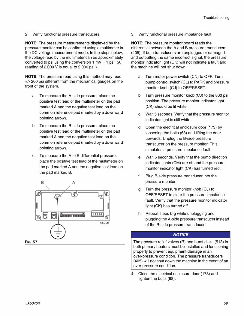
Troubleshooting
3A5376K 59
2. Verify functional pressure transducers.
NOTE: The pressure measurements displayed by the pressure monitor can be confirmed using a multimeter in the DC voltage measurement mode. In the steps below, the voltage read by the multimeter can be approximately converted to psi using the conversion 1 mV = 1 psi. (A reading of 2.000 V is equal to 2,000 psi.)
NOTE: The pressure read using this method may read +/- 200 psi different from the mechanical gauges on the front of the system.
a. To measure the A-side pressure, place the positive test lead of the multimeter on the pad marked A and the negative test lead on the common reference pad (marked by a downward pointing arrow).
b. To measure the B-side pressure, place the positive test lead of the multimeter on the pad marked A and the negative test lead on the common reference pad (marked by a downward pointing arrow).
c. To measure the A to B differential pressure, place the positive test lead of the multimeter on the pad marked A and the negative test lead on the pad marked B.
3. Verify functional pressure imbalance fault.
NOTE: The pressure monitor board reads the differential between the A and B pressure transducers (405). If both transducers are unplugged or damaged and outputting the same incorrect signal, the pressure monitor indicator light (CK) will not indicate a fault and the machine will not shut down.
a. Turn motor power switch (CN) to OFF. Turn pump control switch (CL) to PARK and pressure monitor knob (CJ) to OFF/RESET.
b. Turn pressure monitor knob (CJ) to the 800 psi position. The pressure monitor indicator light (CK) should be lit white.
c. Wait 5 seconds. Verify that the pressure monitor indicator light is still white.
d. Open the electrical enclosure door (173) by loosening the bolts (68) and lifting the door upwards. Unplug the B-side pressure transducer on the pressure monitor. This simulates a pressure imbalance fault.
e. Wait 5 seconds. Verify that the pump direction indicator lights (CM) are off and the pressure monitor indicator light (CK) has turned red.
f. Plug B-side pressure transducer into the pressure monitor.
g. Turn the pressure monitor knob (CJ) to OFF/RESET to clear the pressure imbalance fault. Verify that the pressure monitor indicator light (CK) has turned off.
h. Repeat steps b-g while unplugging and plugging the A-side pressure transducer instead of the B-side pressure transducer.
4. Close the electrical enclosure door (173) and tighten the bolts (68).
FIG. 57
NOTICE
The pressure relief valves (R) and burst disks (513) in both primary heaters must be installed and functioning properly to prevent equipment damage in an over-pressure condition. The pressure transducers (405) will not shut down the machine in the event of an over-pressure condition.

Repair
60 3A5376K
Repair
Repair Proportioning Pumps
1. Perform Flushing, page 42.
2. Perform Shutdown, page 39.
3. Perform Pressure Relief Procedure, page 41.
NOTE: Use drop cloth or rags to protect the proportioner and surrounding area from spills.
4. Disconnect the B (resin) side fluid inlet (F) line, the inlet y-strainer (127), and hard tube (57). Remove the pin (213) from the clevis (317) to disconnect the pump from the hydraulic cylinder (201). Remove the four screws (203) holding the pump to the spacers (313) of the cylinder. Take the pump assembly to a workbench.
5. Disconnect the A (ISO) side fluid inlet (F) line, the inlet y-strainer (127), and the hard tube (55). Use the pin extractor tool (101) to remove the pin (213), which disconnects the pump from hydraulic cylinder (201). Remove the four screws (203) holding the pump to the spacers (313) of the cylinder. Take the pump assembly to a workbench.
6. See fluid pump (Z) manual for repair instructions.
7. Reconnect the fluid pump (Z) in the reverse order. Torque the screws (203) to 200 in.-lb (22.6 N•m).
NOTICE
Proper system setup, startup, and shutdown procedures are critical to electrical equipment reliability. The following procedures ensure steady voltage. Failure to follow these procedures will cause voltage fluctuations that can damage electrical equipment and void the warranty.
FIG. 58Torque to 200 in.-lb (22.6 N•m)1
213
201317
313
57
203 1
127
FIG. 59
Torque to 200 in.-lb (22.6 N•m)1
203
213201
313 101
55
1
127

Repair
3A5376K 61
Change Hydraulic Fluid and Filter
NOTE: Change break-in oil in a new system after the first 250 hours of operation or within 3 months, whichever comes first.
Table 5: Frequency of Oil Changes
1. Follow Shutdown, page 39.
2. Follow Pressure Relief Procedure, page 41.
3. Allow hydraulic fluid to cool.
4. Place a pan under the reservoir drain plug (16f) to catch oil.
5. Remove the drain plug (16f).
6. Place a rag around base of oil filter (119) to prevent oil from spilling. Unscrew filter 1/4-3/4 turn to break air lock in filter. Wait five minutes to allow oil in filter to drain back into reservoir. Unscrew filter and remove.
7. Reinstall drain plug (16f).
8. Replace filter (119).
a. Coat filter seal with fresh oil.
NOTE: Make sure old oil filter seal is not stuck to the filter manifold.
b. Screw filter on snug, then an additional 1/4 turn.
9. Refill reservoir with approved hydraulic fluid. See Table 6: Approved Anti-Wear (AW) Hydraulic Oils (page 62). Verify oil level on dipstick (BN).
10. Proceed with normal operation.
NOTE: Upon starting motor, hydraulic pump may make a screeching noise until primed. If this noise continues for more than 30 seconds, switch off motor control.
Ambient Temperature Recommended Frequency
0 to 90°F(-17 to 32°C)
1000 hours or 12 months, whichever comes first
90°F and above (32°C and above)
500 hours or 6 months, whichever comes first
FIG. 60
16f
119
FIG. 61
BN
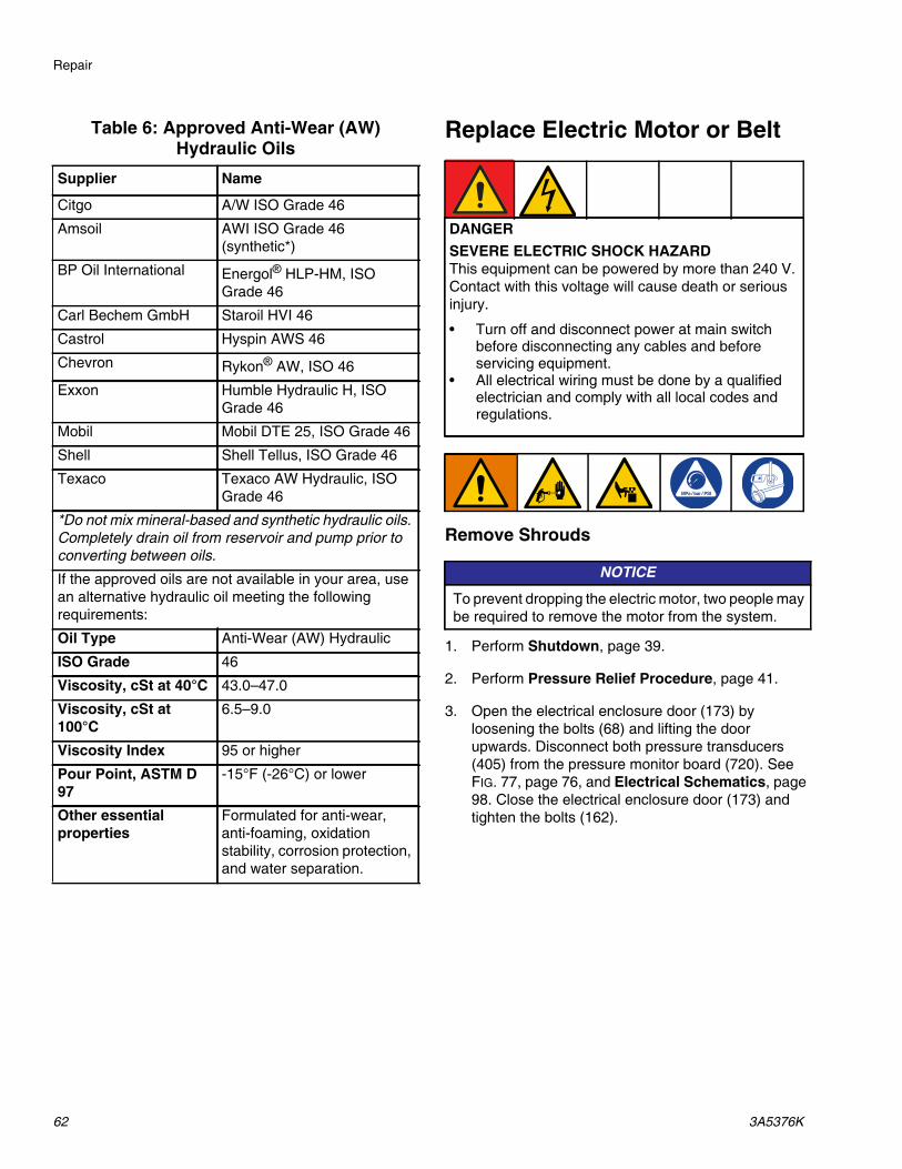
Repair
62 3A5376K
Table 6: Approved Anti-Wear (AW) Hydraulic Oils
Replace Electric Motor or Belt
Remove Shrouds
1. Perform Shutdown, page 39.
2. Perform Pressure Relief Procedure, page 41.
3. Open the electrical enclosure door (173) by loosening the bolts (68) and lifting the door upwards. Disconnect both pressure transducers (405) from the pressure monitor board (720). See FIG. 77, page 76, and Electrical Schematics, page 98. Close the electrical enclosure door (173) and tighten the bolts (162).
Supplier Name
Citgo A/W ISO Grade 46
Amsoil AWI ISO Grade 46 (synthetic*)
BP Oil International Energol® HLP-HM, ISO Grade 46
Carl Bechem GmbH Staroil HVI 46
Castrol Hyspin AWS 46
Chevron Rykon® AW, ISO 46
Exxon Humble Hydraulic H, ISO Grade 46
Mobil Mobil DTE 25, ISO Grade 46
Shell Shell Tellus, ISO Grade 46
Texaco Texaco AW Hydraulic, ISO Grade 46
*Do not mix mineral-based and synthetic hydraulic oils. Completely drain oil from reservoir and pump prior to converting between oils.
If the approved oils are not available in your area, use an alternative hydraulic oil meeting the following requirements:
Oil Type Anti-Wear (AW) Hydraulic
ISO Grade 46
Viscosity, cSt at 40°C 43.0–47.0
Viscosity, cSt at 100°C
6.5–9.0
Viscosity Index 95 or higher
Pour Point, ASTM D 97
-15°F (-26°C) or lower
Other essential properties
Formulated for anti-wear, anti-foaming, oxidation stability, corrosion protection, and water separation.
DANGER
SEVERE ELECTRIC SHOCK HAZARDThis equipment can be powered by more than 240 V. Contact with this voltage will cause death or serious injury.
• Turn off and disconnect power at main switch before disconnecting any cables and before servicing equipment.
• All electrical wiring must be done by a qualified electrician and comply with all local codes and regulations.
NOTICE
To prevent dropping the electric motor, two people may be required to remove the motor from the system.

Repair
3A5376K 63
4. Remove mounting bolts (not provided) from the bottom frame and move the system away from the wall.
5. Remove upper bolts (3). Tilt the electrical enclosure (C) down to gain access to the motor cover.
6. Remove motor and belt covers (123, 131). Lift cover (123) and loosen the silver bracket (70) fasteners. Lift the silver bracket (70) off of the fasteners and set aside. Remove the belt covers (131, 132). Remove the heater cover (123). See FIG. 63 and FIG. 64.
FIG. 62
NOTICE
To prevent damage to cables, do not crush or strain any cables near the point where the frame halves hinge.
NOTICE
To prevent damage to the overtemperature switch, carefully remove the covers.
FIG. 63
FIG. 64
123
132
131
C
3
ti32484a
134
131
132
70
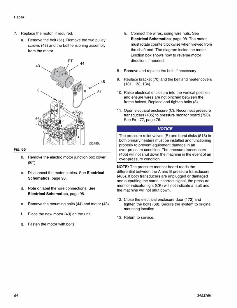
Repair
64 3A5376K
7. Replace the motor, if required.
a. Remove the belt (51). Remove the two pulley screws (48) and the belt tensioning assembly from the motor.
b. Remove the electric motor junction box cover (BT).
c. Disconnect the motor cables. See Electrical Schematics, page 98.
d. Note or label the wire connections. See Electrical Schematics, page 98.
e. Remove the mounting bolts (44) and motor (43).
f. Place the new motor (43) on the unit.
g. Fasten the motor with bolts.
h. Connect the wires, using wire nuts. See Electrical Schematics, page 98. The motor must rotate counterclockwise when viewed from the shaft end. The diagram inside the motor junction box shows how to reverse motor direction, if needed.
8. Remove and replace the belt, if necessary.
9. Replace bracket (70) and the belt and heater covers (131, 132, 134).
10. Raise electrical enclosure into the vertical position and ensure wires are not pinched between the frame halves. Replace and tighten bolts (3).
11. Open electrical enclosure (C). Reconnect pressure transducers (405) to pressure monitor board (720). See FIG. 77, page 76.
NOTE: The pressure monitor board reads the differential between the A and B pressure transducers (405). If both transducers are unplugged or damaged and outputting the same incorrect signal, the pressure monitor indicator light (CK) will not indicate a fault and the machine will not shut down.
12. Close the electrical enclosure door (173) and tighten the bolts (68). Secure the system to original mounting location.
13. Return to service.
FIG. 65
51
48
BT43
3
44
ti32485a
NOTICE
The pressure relief valves (R) and burst disks (513) in both primary heaters must be installed and functioning properly to prevent equipment damage in an over-pressure condition. The pressure transducers (405) will not shut down the machine in the event of an over-pressure condition.

Repair
3A5376K 65
Replace Pressure Transducers
1. Flush. See Flushing, page 42.
2. Perform Shutdown, page 39, and Pressure Relief Procedure, page 41.
3. Disconnect transducer cables from the pressure control board.
4. Remove wire ties constraining transducer cable and remove cable from electrical enclosure (C).
5. Remove transducer (405) from manifold (AA).
6. Install o-ring (416) on new transducer (405).
7. Install transducer in manifold. Mark end of cable with tape (red is transducer A, blue is transducer B).
8. Route new cable into electrical enclosure (C) and thread into bundle as before. Attach cable ties to bundle as before.
9. Connect A-side pressure transducer cable to the pressure control board. Connect B-side pressure transducer cable to pressure control board.
NOTE: The pressure monitor board reads the differential between the A and B pressure transducers (405). If both transducers are unplugged or damaged and outputting the same incorrect signal, the pressure monitor indicator light (CK) will not indicate a fault and the machine will not shut down.
DANGER
SEVERE ELECTRIC SHOCK HAZARDThis equipment can be powered by more than 240 V. Contact with this voltage will cause death or serious injury.
• Turn off and disconnect power at main switch before disconnecting any cables and before servicing equipment.
• All electrical wiring must be done by a qualified electrician and comply with all local codes and regulations.
FIG. 66: Transducer Cables
FIG. 67
NOTICE
The pressure relief valves (R) and burst disks (513) in both primary heaters must be installed and functioning properly to prevent equipment damage in an over-pressure condition. The pressure transducers (405) will not shut down the machine in the event of an over-pressure condition.
A
B
AA
405
406

Repair
66 3A5376K
Replace Primary Heater
Replace Heater Element
1. Flush. See Flushing, page 42.
2. Perform Shutdown, page 39.
3. Perform Pressure Relief Procedure, page 41.
4. Wait for heaters to cool.
5. Remove heater cover (134 or 135).
6. Disconnect heater element wires from heater wire connector inside the electrical enclosure (C). See Electrical Schematics, page 98. Test with ohmmeter.
Table 7: Heater Resistance
7. If the thermocouple is on the heater element, remove the thermocouple (511 or 512) to avoid damage. See Replace Thermocouple, page 68.
8. Use a wrench to remove the heater element (508). Inspect element. It should be relatively smooth and shiny. Replace element if there is a crusted, burnt ash-like material adhered to the element, or if the sheath shows pitting marks.
9. Install the new heater elements (508), holding the mixer (510) so it does not block the thermocouple port. Torque to 120 ft-lbs (163 N•m).
10. Install the thermocouple (511 or 512), if removed earlier. See Replace Thermocouple, page 68.
11. Reconnect the wires inside the electrical enclosure. See Electrical Schematics, page 98.
12. Replace heater cover (134 or 135).
Line Voltage
The heater outputs its rated wattage at 230 VAC. Low line voltage will reduce power available and the heater will not perform at full capacity.
DANGER
SEVERE ELECTRIC SHOCK HAZARDThis equipment can be powered by more than 240 V. Contact with this voltage will cause death or serious injury.
• Turn off and disconnect power at main switch before disconnecting any cables and before servicing equipment.
• All electrical wiring must be done by a qualified electrician and comply with all local codes and regulations.
SystemTotal Heater Wattage Element
Ohms per Element
GH-2 10 kW2550 18-21
GH-4 15 kW

Repair
3A5376K 67
Repair Heater Overtemperature Switch
1. Perform Shutdown, page 39.
2. Wait for heaters to cool.
3. Disconnect overtemperature switches (509) from cable (88 or 89). Test across spade terminals with ohmmeter.
NOTE: If the resistance is not approximately 0 ohms, the overtemperature switch (509) needs to be replaced.
4. If the switch fails the test, remove the screws. Discard the failed switch. Apply a thin layer of thermal compound 110009, install a new switch (509) in the same location on housing (501). Secure with screws (513) and reconnect cables (88 or 89). FIG. 68
88 or 89513
509
501

Repair
68 3A5376K
Replace Thermocouple
1. Perform Shutdown, page 39.
2. Follow Pressure Relief Procedure, page 41.
3. Wait for heaters to cool.
4. Remove heater shroud (134 or 135).
5. Disconnect thermocouple wires from temperature control module. See Heater Wiring, page 100.
6. Feed thermocouple wires out of electrical enclosure (C). Note path as wires must be replaced in the same way.
7. See FIG. 69, page 69. Loosen ferrule nut (BV). Remove thermocouple (511) from heater housing (501), then remove thermocouple housing (BR). Do not remove the thermocouple adapter (506) unless it is also necessary to remove the mixer (510). If adapter must be removed, ensure that mixer (510) is out of the way when replacing the adapter.
8. Replace thermocouple. See FIG. 69.
a. Remove protective tape from thermocouple (511) tip.
b. Apply PTFE tape and thread sealant to male threads and tighten thermocouple housing (BR) into adapter (506).
c. Push in thermocouple (511) so tip contacts heater element (508).
d. Holding thermocouple (511) against heater element, tighten ferrule nut (BV) 1/4 turn past finger-tight.
9. Route thermocouple wires into electrical enclosure (C) and thread into bundle as before. Reconnect wires to board.
10. Replace heater shroud.
11. Turn on heaters A and B simultaneously to test. Temperatures should rise at the same rate. If one heater is low, loosen ferrule nut (BV) and tighten thermocouple housing (BR) to ensure the thermocouple (511) tip contacts element (508).
DANGER
SEVERE ELECTRIC SHOCK HAZARDThis equipment can be powered by more than 240 V. Contact with this voltage will cause death or serious injury.
• Turn off and disconnect power at main switch before disconnecting any cables and before servicing equipment.
• All electrical wiring must be done by a qualified electrician and comply with all local codes and regulations.

Repair
3A5376K 69
FIG. 69: Thermocouple
Apply PTFE tape and thread sealant1
Apply 110009 thermal heatsink compound2
12
511 cable
BV
511
510
BR
506501 508
509

Repair
70 3A5376K
Diagnose Heated Hose
Refer to your heated hose manual for hose replacement parts.
Check Hose Wires
1. Perform Shutdown, page 39.
NOTE: Whip hose must be connected.
2. Remove cover (71). See FIG. 71.
3. Disconnect system wires (139) from the proportioner.
4. Disconnect hose wires from terminal block (AS).
5. Using an ohmmeter, check between the hose wires. There should be continuity.
6. If hose fails test, retest at each length of hose from the system out to the gun, including whip hose, until failure is isolated.
7. Reconnect wires and install cover (71).
Check Hose Power Connectors
1. Perform Shutdown, page 39.
NOTE: Whip hose must be connected.
2. Disconnect power wire harness from terminal block (AS).
3. Use an ohmmeter to check for continuity between the two terminals on the terminal block.
4. If the hose fails the test, re-test at each length of hose, including whip hose, until the failure is identified.FIG. 70
139
AS
Hose wires
FIG. 71: Heated Hose Electrical Junction Box
71

Repair
3A5376K 71
Check FTS Cables
1. Perform Shutdown, page 39.
2. Disconnect FTS cable (163) at proportioner. See FIG. 72.
3. Test with ohmmeter between pins of cable connector.
4. If cable fails test, see Repair Fluid Temperature Sensor (FTS), page 72.
FIG. 72: Disconnect FTS Cable
163
Pins Result
1 to 2 Approximately 35 ohms per 50 ft (15.2 m) of hose, plus approximately 10 ohms for FTS
1 to 3 Infinity

Repair
72 3A5376K
Repair Fluid Temperature Sensor (FTS)
Installation
The fluid temperature sensor (FTS) is supplied with system. Install FTS between main hose and whip hose. Refer to your heated hose manual for instructions.
Test/Removal
1. Perform Shutdown, page 39.
2. Follow Pressure Relief Procedure, page 41.
3. Remove tape and protective covering from FTS. Disconnect sensor cable (BC). Test with ohmmeter between pins of cable connector.
4. If FTS fails, replace FTS.
a. Disconnect air hoses (BB) and electrical connectors (BA).
b. Disconnect FTS from fluid hoses (BE).
c. Remove ground wire (BF) from ground screw on underside of FTS.
d. Remove FTS probe (BG) from component A (ISO) side of hose.
Pins Result
1 to 2 Approximately 10 ohms1 to 3 Infinity3 to FTS groundscrew
0 ohms
1 to FTS component A fitting (ISO)
Infinity
FIG. 73
BE
FTS
BF
BB
BG
BC
BA

Repair
3A5376K 73
Diagnose and Replace Hose Transformer
Transformer Primary Check
NOTE: Refer to Electrical Schematics, page 98, for circuit breaker and wire identification.
1. Perform Shutdown, page 39.
2. Open the electrical enclosure door (173) by loosening the bolts (68) and lifting the door upwards.
3. Turn off circuit breaker CB3.
4. Use an ohmmeter to test for continuity between the CB3-2 and RLY-T1 wires; there should be continuity.
a. If there is no continuity, Replace Transformer.
b. If there is continuity, follow Transformer Secondary Check.
5. Turn on circuit breaker CB3.
Transformer Secondary Check
NOTE: Refer to Electrical Schematics, page 98, for circuit breaker and wire identification.
1. Perform Shutdown, page 39.
2. Open the electrical enclosure door (173) by loosening the bolts (68) and lifting the door upwards.
3. Turn off circuit breaker CB5 and disconnect the hose wires in the hose electrical junction box. See FIG. 70, page 70.
4. Use an ohmmeter to test for continuity between the SEC X1 and the terminal for each hose length; there should be continuity.
a. If there is no continuity, Replace Transformer.
b. If there is continuity, reconnect the hose wires in the electrical junction box. See FIG. 70, page 70. Turn on circuit breaker CB5. Close the electrical enclosure door (173) and tighten the bolts (68).
Replace Transformer
1. Perform Shutdown, page 39.
2. Remove the transformer cover (128). See Proportioner Parts, page 78, and FIG. 13, page 26.
3. Remove transformer mounting bolts (15).
4. Disconnect the transformer wires. See Electrical Schematics, page 98, and Adjust Hose Transformer Wiring, page 26.
5. Replace transformer and reconnect transformer wires. Refer to Electrical Schematics, page 98, and Adjust Hose Transformer Wiring, page 26.
6. Reinstall transformer mounting bolts (15).
7. Reinstall transformer cover (128).
DANGER
SEVERE ELECTRIC SHOCK HAZARDThis equipment can be powered by more than 240 V. Contact with this voltage will cause death or serious injury.
• Turn off and disconnect power at main switch before disconnecting any cables and before servicing equipment.
• All electrical wiring must be done by a qualified electrician and comply with all local codes and regulations.

Repair
74 3A5376K
Replace Power Supply
1. Perform Shutdown, page 39.
2. Open electrical enclosure (C).
3. Disconnect input and output cables from both sides of the power supply. See Electrical Schematics, page 98.
4. Insert a flat head screw driver in the mounting tab on the bottom of the power supply to remove from the din rail.
5. Install new power supply in reverse order.
6. Close electrical enclosure (C).
Replace Power Supply Fuse
1. Perform Shutdown, page 39.
2. Open electrical enclosure (C).
3. Open fuse enclosure F1 or F2. See Electrical Enclosure, page 93.
4. Remove blown or faulty fuse (659). Replace with new fuse.
5. Shut fuse enclosures firmly. Close electrical enclosure (C).
DANGER
SEVERE ELECTRIC SHOCK HAZARDThis equipment can be powered by more than 240 V. Contact with this voltage will cause death or serious injury.
• Turn off and disconnect power at main switch before disconnecting any cables and before servicing equipment.
• All electrical wiring must be done by a qualified electrician and comply with all local codes and regulations.
FIG. 74
ti32486b
Power supply
DANGER
SEVERE ELECTRIC SHOCK HAZARDThis equipment can be powered by more than 240 V. Contact with this voltage will cause death or serious injury.
• Turn off and disconnect power at main switch before disconnecting any cables and before servicing equipment.
• All electrical wiring must be done by a qualified electrician and comply with all local codes and regulations.
FIG. 75

Repair
3A5376K 75
Replace Surge Protector
1. Perform Shutdown, page 39.
2. Open the electrical enclosure door (173) by loosening the bolts (68) and lifting the door upwards.
3. Loosen connections on terminals F1-1 and F1-2 on din rail. See Electrical Schematics, page 98.
4. Follow the two remaining wires (BU) from the surge protector (621) to the zip-tied wire loom (BW). Cut off one end of the zip tie and peel back the loom on each wire. Unplug both wires.
5. Loosen nuts (623) and remove the faulty surge protector (621).
6. Install the new surge protector in reverse order. Reinstall looms (BW) with new zip ties. Be sure to connect the wires according to their labels.
7. Close the electrical enclosure door (173) and tighten the bolts (68).
DANGER
SEVERE ELECTRIC SHOCK HAZARDThis equipment can be powered by more than 240 V. Contact with this voltage will cause death or serious injury.
• Turn off and disconnect power at main switch before disconnecting any cables and before servicing equipment.
• All electrical wiring must be done by a qualified electrician and comply with all local codes and regulations.
FIG. 76
BU
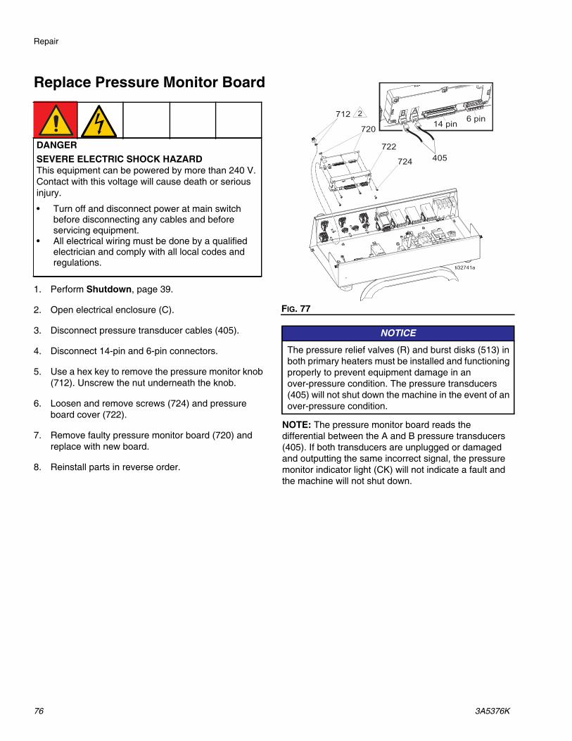
Repair
76 3A5376K
Replace Pressure Monitor Board
1. Perform Shutdown, page 39.
2. Open electrical enclosure (C).
3. Disconnect pressure transducer cables (405).
4. Disconnect 14-pin and 6-pin connectors.
5. Use a hex key to remove the pressure monitor knob (712). Unscrew the nut underneath the knob.
6. Loosen and remove screws (724) and pressure board cover (722).
7. Remove faulty pressure monitor board (720) and replace with new board.
8. Reinstall parts in reverse order.
NOTE: The pressure monitor board reads the differential between the A and B pressure transducers (405). If both transducers are unplugged or damaged and outputting the same incorrect signal, the pressure monitor indicator light (CK) will not indicate a fault and the machine will not shut down.
DANGER
SEVERE ELECTRIC SHOCK HAZARDThis equipment can be powered by more than 240 V. Contact with this voltage will cause death or serious injury.
• Turn off and disconnect power at main switch before disconnecting any cables and before servicing equipment.
• All electrical wiring must be done by a qualified electrician and comply with all local codes and regulations.
FIG. 77
NOTICE
The pressure relief valves (R) and burst disks (513) in both primary heaters must be installed and functioning properly to prevent equipment damage in an over-pressure condition. The pressure transducers (405) will not shut down the machine in the event of an over-pressure condition.

Repair
3A5376K 77
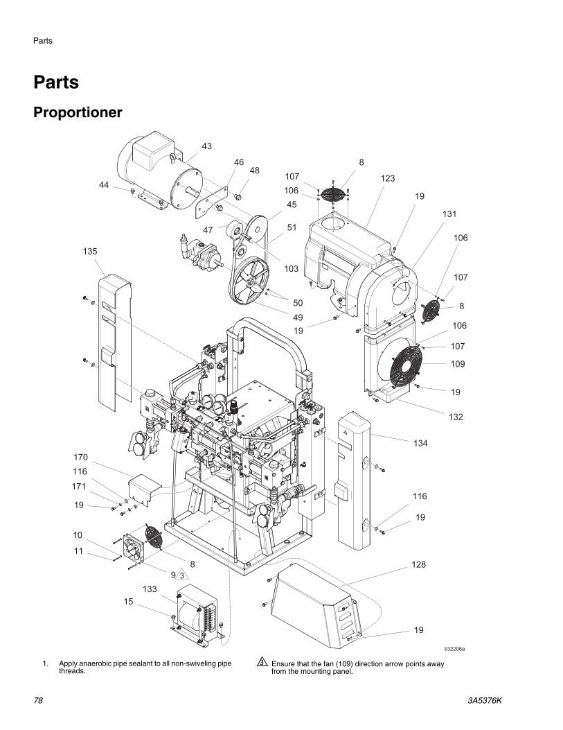
Parts
78 3A5376K
Parts
Proportioner
1. Apply anaerobic pipe sealant to all non-swiveling pipe threads.
Ensure that the fan (109) direction arrow points away from the mounting panel.
3
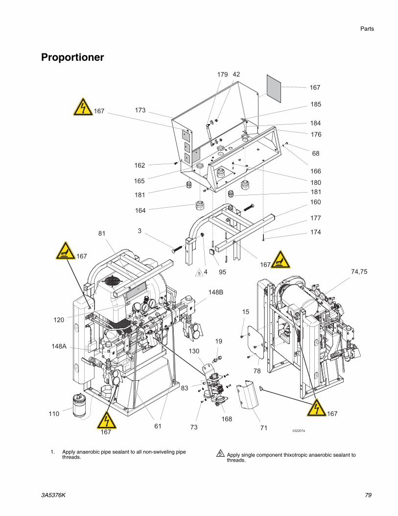
Parts
3A5376K 79
Proportioner
Apply single component thixotropic anaerobic sealant to threads.
51. Apply anaerobic pipe sealant to all non-swiveling pipe threads.

Parts
80 3A5376K
Proportioner
1. Apply anaerobic pipe sealant to all non-swiveling pipe threads.
Apply high viscosity anaerobic sealant to threads.19
Fill reservoir (16) with hydraulic oil.22

Parts
3A5376K 81
Proportioner

Parts
82 3A5376K
GH-2 and GH-4
Ref. Part Description Qty.
1 - - - - - CART, weldment, hr2, paint 1
2 17V435 HEATER, 5 kw, 1 zone, thermocouple (GH-2 10 kW only)
2
17V436 HEATER, 7.5 kw, 1 zone, thermocouple (GH-4 only)
2
3 127277 BOLT, carriage, 1/2-13 X 3.5 L 4
4 112731 NUT, hex, flanged 4
8* 115836 GUARD, finger 3
9 17V437 FAN, cooling, 120 mm, 24 VDC 1
10 103181 WASHER, lock ext 4
11 117683 SCREW, mach, phil pan hd 4
15 111800 SCREW, cap, hex hd 20
16 247826 RESERVOIR, assembly, hydraulic
1
16a 247778 HOUSING, inlet 1
16b 247771 GASKET, inlet 1
16c 247777 TUBE, inlet 1
16d 247770 TUBE, return 1
16e 116919 FILTER, inlet 1
16f 255032 FITTING, plug, SAE 1
16g 255021 FITTING, straight 1
17 117556 FITTING, nipple, #8 JIC x 1/2 npt 1
18 17V438 BRACKET, retaining, tank, paint 1
19* 113796 SCREW, flanged, hex hd 36
20 17V497 ADAPTER, hydraulic gage 1
21 17G624 TUBE, gauge, pressure 1
22 15H524 ACCUMULATOR, pressure, 1/4 npt
1
23 119789 FITTING, elbow, street, 45 deg, 1
24 112567 GAUGE, pressure, fluid 1
25 247829 COOLER, hydraulic, complete 1
26 17G611 BRACKET, mntg, pump, hyd, lf, paint (GH-2 only)
1
17G612 BRACKET, mntg, pump, hyd, hf (GH-4)
27 247855 PUMP, hydraulic (GH-2 only) 1
255019 PUMP, hydraulic (GH-4 only)28† - - - - - KNOB, compensator 1
29† - - - - - KNOB, lock, compensator 1
30 15H512 LABEL, control 1
31† - - - - - SCREW, set, 1/4-20 sst, 1.25 lg 1
32 110792 FITTING, elbow, male, 90 deg 1
33 115764 FITTING, elbow, 90 1
34 120804 FITTING, elbow, 1/2npt x 1 JIC (GH-2 only)
1
255020 FITTING, elbow, 1 1/16 SAE x 1/2 tube (GH-4 only)
35 247793 HOSE, inlet, coupled 1
36 15G784 HOSE, coupled 2
37 121321 FITTING, elbow, SAE x JIC (GH-2 only)
1
121320 FITTING, elbow, SAE x JIC (GH-4 only)
1
38 15T895 HOSE, hydraulic supply 1
39 117464 CLAMP, hose, micro 1.75 max dia.
1
40 112161 SCREW, mach, hex, wshr hd 2
41 112586 SCREW, cap, hex hd 1
42 110996 NUT, hex, flange head 3
43 247816 MOTOR, 230 VAC, 4.0 hp (GH-2 only)
1
247785 MOTOR, 230 VAC, 7.5 hp (GH-4 only)
1
44 113802 SCREW, hex hd, flanged 4
45 247845 PULLEY, drive, vee 1
46 15H207 BRACKET, tensioner 1
47 247853 ADJUSTER, belt, tensioner 1
48 111802 SCREW, cap, hex hd 2
49 15E410 PULLEY, fan (GH-2 only) 1
247856 PULLEY, fan (GH-4 only) 1
50 120087 SCREW, set, 1/4 x 1/2 2
51 803889 BELT, AX46 1
52 25D460 PUMP, hydraulic, iso and resin (GH-2 only)
1
25D459 PUMP, hydraulic, iso and resin (GH-4 only)
1
53 15B456 GASKET, manifold 1
54 17V439 MANIFOLD, fluid 1
55 17G600 TUBE, fluid, iso, heater, inlet 1
56 17G601 TUBE, fluid, iso, heater, outlet 1
57 17G603 TUBE, fluid, res, heater, inlet 1
58 17G604 TUBE, fluid, res, heater, outlet 1
59 117677 FITTING, reducer #6 x #10 (jic) 1
60 117502 FITTING, reducer #5 x #8 (JIC) 1
61 16W043 TUBE, pressure relief 2
64 - - - - - SLEEVE, wire,.50 id 3
65 17G668 NUT, wire, gray 2
66 295731 NUT, wire 2
67 118459 FITTING, union, swivel, 3/4" 2
68 113161 SCREW, flange, hex hd 4
69 - - - - - GROMMET 1
70 17V440 BRACKET, retaining, tank, shroud, pnt
1
71 25A234 ENCLOSURE, cover, painted 1
73 16X129 SCREW, mach, Phillips, tooth wash
4
74 - - - - - BUSHING, strain relief, 1/2 npt 1
Ref. Part Description Qty.

Parts
3A5376K 83
Replacement safety labels, tags, and cards are available at no cost.
* Parts included in Kit 17V446 (purchase separately).
† Parts included in Kit 17G606 (purchase separately).
75 - - - - - NUT, strain relief, 1/2 npt 1
76 127816 BUSHING, strain relief 2
77 17F532 TIE, cable, fir tree 17
78 17G599 COVER, access, hr2, paint 1
81 17V442 LABEL, Gusmer branding, GH-2 1
82 114269 GROMMET, rubber 1
83 16P338 SCREW, MACH, serrated hex head
2
84 125943 NUT, serrated flange 2
85 101032 BOLT, machine 2
88 17V444 HARNESS, OT A 1
89 17V445 HARNESS, OT B 1
91 121309 FITTING, adapter, SAE-ORB X JIC
2
93 299520 CAP, 9/16-18 JIC cap, aluminum 1
94 299521 CAP, 1/2-20 JIC cap, aluminum 1
95 111218 CAP, tube, square 4
97 16W654 INSULATOR, foam, heater 8
101 296607 TOOL, clevis pin extractor 1
103 C19843 SCREW, cap, sockethead 1
105 C20487 FITTING, nipple, hex 2
106* 114027 WASHER, flat 12
107* - - - - - RIVET, pop, 5/32 dia. 12
109 117284 GRILL, fan guard 1
110 296731 RESERVOIR, lube hose assembly
1
113 206995 FLUID, TSL, 1 qt. 2
116 17H155 WASHER, flat, nylon 4
118 116915 CAP, breather filler 1
119 247792 FILTER, oil, 18-23 psi bypass 1
120 15Y118 LABEL, made in the USA 1
121 106569 TAPE, electrical 1
122 125871 TIE, cable, 7.50 inch 22
123* 17V446 COVER, motor, painted 1
127 17G644 KIT, assembly, pair, inlet 1
128 17G623 COVER, transformer, paint 1
130 17G620 BRACKET, connector, hose, paint 1
131 17V447 COVER, belt, upper, hr2, paint 1
132 17V448 COVER, belt, lower, hr2, paint 1
133 17V449 TRANSFORMER, 4090 VA (GH-2 only)
1
25P661 TRANSFORMER, 5310 VA (GH-4 only)
1
134 17V450 COVER, heater, right, paint 1
135 17V451 COVER, heater, left, paint 1
136 17V452 CABLE, M12, A prox 1
137 17V453 CABLE, M12, B prox 1
Ref. Part Description Qty.
138 17V454 HARNESS, motor (GH-2 only) 1
17H959 HARNESS, motor (GH-4 only) 1
139 17V455 HARNESS, hose 1
144 15G782 HOSE, coupled 1
145 116793 FITTING 1
148 128417 LABEL, A/B 1
157 127368 SLEEVE, split, wire,1.50 id 2
160 17V456 BRACKET, electrical box, painted 1
161 17B524 HOSE, hydraulic supply 1
162 17V457 BOLT, shoulder, 1/4-20 2
163 17V458 CABLE, hose control, 72" 1
164 120858 BUSHING, strain relief, m40 thread
4
165 120859 NUT, strain relief, m40 thread 4
166 16V153 WASHER, retaining 2
167 25D512 LABEL, safety 1
168 24W204 ENCLOSURE, terminal block 1
170 17V459 COVER, hydraulic pump, clear 1
171 17V460 WASHER, epdm, 1/4" 2
173 17V462 COVER, electrical, paint 1
174 105170 SCREW, cap hex hd 4
175 261669 KIT, fluid temp sensor, coupler 1
176 17V463 GASKET, foam 1
177 100016 WASHER, plain 4
179 17V464 SPRING, gas 1
180 115942 NUT, hex, flange head 1
181 121171 GRIP, cord, 35-.63, 3/4 2
182 - - - - - LABEL, identification 1
183 17V465 HARNESS, 230 V/1-phase 1
17V491 HARNESS, 230 V/3-phase (GH-2, Series A only)
1
17H961 HARNESS, 230 V/3-phase, (GH-2 Series B and later, GH-4)
1
17V736 HARNESS, 400 V/3-phase, neutral (GH-2 only)
1
17H960 HARNESS, 400 V/3-phase, neutral (GH-4 only)
184 194337 WIRE, grounding, door 1
185 113504 NUT, keps, hex hd 2
186 128053 TOOL, screwdriver 1
187 17G667 FUSE, 2.5 amp, 250 V, time-lag 4
Ref. Part Description Qty.
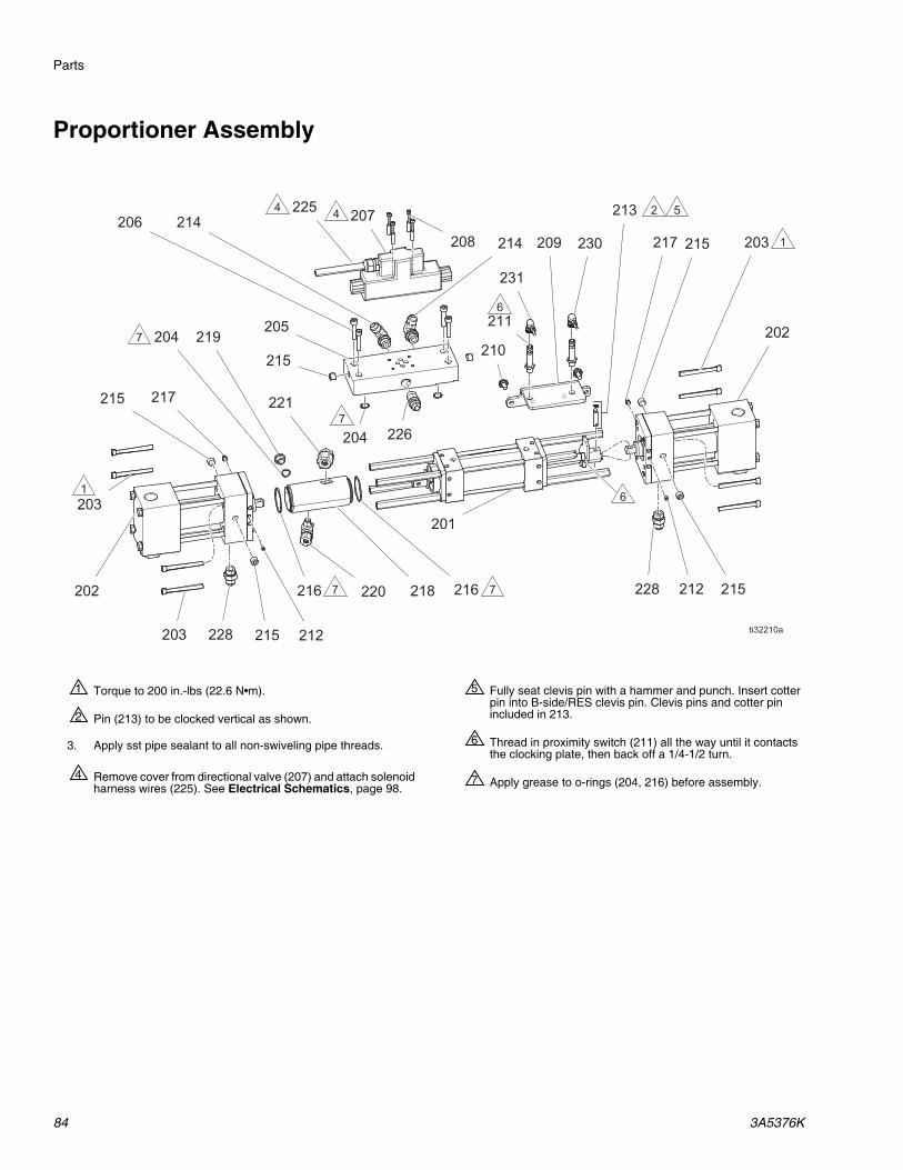
Parts
84 3A5376K
Proportioner Assembly
Torque to 200 in.-lbs (22.6 N•m).1
Pin (213) to be clocked vertical as shown.2
3. Apply sst pipe sealant to all non-swiveling pipe threads.
Fully seat clevis pin with a hammer and punch. Insert cotter pin into B-side/RES clevis pin. Clevis pins and cotter pin included in 213.
5
Thread in proximity switch (211) all the way until it contacts the clocking plate, then back off a 1/4-1/2 turn.
6
Apply grease to o-rings (204, 216) before assembly.7Remove cover from directional valve (207) and attach solenoid harness wires (225). See Electrical Schematics, page 98.
4

Parts
3A5376K 85
Proportioner Assembly
* Parts included in Kit 261863 (purchase separately).
Ref. Part Description Qty.
201 17G499 CYLINDER, hydraulic, w/ spacers 1
202 247576 PUMP, proportioner, 140 (GH-2 only)
2
247377 PUMP, proportioner, 120 (GH-4 only)
2
203 295824 SCREW, cap, sh, 5/16 x 3 8
204 112793 PACKING, o-ring 3
205 17G531 MANIFOLD, hyd, hr2 1
206 113467 SCREW, cap, socket hd 4
207 120299 VALVE, directional, hydraulic 1
208 C19986 SCREW, cap, socket, hd 4
209 17V466 BRACKET, prox switch 1
210 111800 SCREW, cap, hex hd 2
211 17G605 SENSOR, prox, switch, hr2 2
212 M70430 SCREW, set, socket (1/4 28 x .19) 4
213 296653 KIT, clevis pin 2
214 121312 FITTING, elbow, SAE X JIC 2
215 295225 PLUG, pipe, flush 6
216 106258 PACKING, o-ring 2
217 295229 FITTING, grease, 1/4-28 2
218* - - - - - CYLINDER, lube 1
219 295829 FITTING, plug, 3/8mpt x .343 lg 1
220 295826 FITTING, elbow, 90, 1/4 mpt x 3/8"
1
221 295397 FITTING, elbow, 3/8 mpt x 1/2" 1
225 17G690 HARNESS, valve, solenoid, hr2 1
226 121319 FITTING, adapter, npt x jic 1
228 121309 FITTING, adapter, sae-orb x jic 2
230 17V453 CABLE, m12, B prox 1231 17V452 CABLE, m12, A prox 1
Ref. Part Description Qty.

Parts
86 3A5376K
Proportioner Assembly (continued)
Apply (113500) to threads.3
Torque (819) to 75 ft-lbs (102 N•m).4
Apply thread lube and torque (808) to 38 ft-lbs (52 N•m). If threads are dry, torque to 45 ft-lbs (61 N•m).
5
Seal (816) must be pressed straight into housing (826).9
Torque to 45 ft-lbs (61 N•m).10

Parts
3A5376K 87
Proportioner Assembly (continued)
* Parts included in Kit 261876 (purchase separately).
† Parts included in Kit 247585 (purchase separately).
‡ Parts included in Kit 261747(purchase separately).
Parts included in Kit 247581 (purchase separately).
Parts included in Kit 261845 (purchase separately).
Parts included in Kit 247579 (purchase separately).
Ref. Part Description Qty.
801 110492 PACKING, o-ring 2
802 104319 PACKING, o-ring 2
803*† 261885 CAP, piston 1
804 105445 BALL, (0.5 in.) 1
805 261866 WASHER, flat 4
806 107078 PACKING, o-ring 1
808 261865 SCREW, 9 x 0.38 in., hex hd cap
4
809 107098 PACKING, o-ring 2
810 107167 BALL, sst 1
811 193395 SEAT, carbide 1
812 247583 CYLINDER, 140 proportioner (GH-2 only)
1
261890 CYLINDER, 120 proportioner (GH-4 only)
1
813 - - - - - BEARING, throat, 140 proportioner (GH-2 only)
1
‡ - - - - - BEARING, throat, 120 proportioner (GH-4 only)
1
814 261899 GUIDE, 1 in. ball, seat assembly
1
815 - - - - - SEAL, piston, 140 proportioner (GH-2 only)
1
- - - - - SEAL, piston, 120 proportioner (GH-4 only)
1
816 - - - - - SEAL, throat, 140 proportioner (GH-2 only)
1
‡ - - - - - SEAL, throat, 120 proportioner (GH-4 only)
1
817‡ 295145 GASKET 1
818 - - - - - BUSHING, piston, 140 (GH-2 only)
1
- - - - - BUSHING, piston, 120 GH-4 only)
1
819 261867 GUIDE, 0.5 in. ball, cap 1
822 261897 SPRING, valve 1
823 261903 PUMP, base, proportioner 1
824 261898 TUBE, crossover 1
825 - - - - - SCREW 1
826 261901 FLANGE, outlet 1
827 261875 RETAINER, flange 1
828† - - - - - ROD, piston, 140 (GH-2 only) 1* - - - - - ROD, piston, 120 GH-4 only) 1
829 247587 ADAPTER, throat, 140 (GH-2 only)
1
261868 ADAPTER, throat, 120 (GH-4 only)
1
Ref. Part Description Qty.

Parts
88 3A5376K
Hydraulic Cylinder
* Parts included in Kit 296785 (purchase separately).
† Parts included in Kit 261863 (purchase separately).
Torque spacers (313, 314) and rod (315) to 200 in-lbs (22.5 N•m).1
Torque to 40 +/- 5 ft-lbs (345 +/- 54 N•m).3
4. Apply grease to all soft parts before assembly.
Ref. Part Description Qty.
301 295029 PLATE, retainer 2
302 295030 CYLINDER 1
303* 295031 BUSHING, rod 2
304 296642 PISTON, cylinder, hydraulic 1
305* 295640 O-RING 2
306* 295641 SEAL, u-cup 2
307* 295642 RING, back up 2
308* 296643 RING, wear 1
309* 158776 PACKING, o-ring 2
310* 295644 RING, back up 2
311* 295645 WIPER, rod 2
312* 296644 SEAL, shaft 2
313 295032 SPACER, proportioner pump 7
314 261502 SPACER, reversing switch 1
315 295034 ROD, TIE, hydraulic cylinder 4
316 295035 BLOCK, port 2
317 261864 CLEVIS, hex, proportioner 2
318 17G527 BUSHING, clocking, hr2 1
319 17G529 PLATE, clocking, driver, hr2 1
320† - - - - - ADAPTER, lube, cylinder 1
321 177156 PACKING, o-ring 1
322 295852 NUT, jam, baffle 1
Ref. Part Description Qty.

Parts
3A5376K 89
Fluid Manifold
Replacement safety labels, tags, and cards are available at no cost.
* Parts included in Kit 255150 (purchase separately).
† Parts included in Kit 255149 (purchase separately).
‡ Parts included in Kit 255148 (purchase separately).
Part includes replacement ORB fittings (part 412 and 413).
To order a replacement part, verify the type of fitting used with your fluid manifold (1/2 npt or 3/4 ORB fitting).
Torque to 355-395 in-lbs (40-44.6 N•m).1
Apply sealant (113500) to threads.2
Valve must be closed with handle position as shown on drawing.3
Apply PTFE tape and thread sealant to gauge threads.4
Apply grease on valve.5
6. Apply PTFE tape or thread sealant to all tapered threads.
Ref. Part Description Qty.
401 255228 MANIFOLD, fluid, inlet, etched 1
402*†‡ 247824 VALVE, drain valve 2
403 102814 GAUGE, press, fluid 2
404 162453 FITTING, (1/4 npsm x 1/4 npt) 2
405 24K999 TRANSDUCER, pressure control
2
406†‡ 247788 HANDLE, red 1
407*‡ 247789 HANDLE, blue 1
408*†‡ 112309 NUT, hex, jam 2
412 17Y236 FITTING, 3/4 ORB x #8 JIC 1
117556 FITTING, nipple, #8 JIC x 1/2 npt
1
413 17Y235 FITTING, 3/4 ORB x #10 JIC 1
117557 FITTING, nipple, #10 JIC x 1/2 npt
1
415 100840 FITTING, elbow, street 2
416 111457 PACKING, o-ring 2
417 189285 LABEL, safety, burn 1
418*†‡ 150829 SPRING, compression 2
Ref. Part Description Qty.

Parts
90 3A5376K
Heater
17V435: 5 kW Single Zone Heater, GH-2 10 kW (Shown)
17V436: 7.5 kW Single Zone Heater, GH-4 15 kW
Torque to 120 ft-lbs (163 N•m).1
Torque to 23 ft-lbs (31 N•m).2
Torque to 40 ft-lbs (54 N•m).3
Apply pipe sealant and PTFE tape to all non-swiveling threads and threads without o-rings.
5
Apply lithium grease lubricant to o-rings before assembling in block (510).
6
Position rupture disc housing (513) so that the exhaust hole points away from fitting (508).
7
Apply thermal paste.4

Parts
3A5376K 91
Heater
Ref. Part Description Qty.
17V435 17V436
501 - - - - - HEATER, machined, 1 zone, 3500 psi
1 1
502 124132 O-RING 2 3
503 15H305 FITTING, plug hollow hex 1-3/16 sae
6 5
504 121309 FITTING, adapter, sae-orb x jic 2 2
505 15H304 FITTING, plug 9/16 sae 3 3
506 15H306 ADAPTER, thermocouple, 9/16 x 1/8
1 1
507 120336 O-RING, packing 1 1
508 16A110 HEATER, immersion, (2550 W, 230 V)
2 3
509 15B137 SWITCH, over temperature 1 1
510 15B135 MIXER, immersion heater 2 3
511 117484 SENSOR 1 1
512 124131 SCREW, mach, pnh 2 2
513 24U856 HOUSING, rupture disc 1 1

Parts
92 3A5376K
Fluid Inlet Kits
17G644
Position ball valves as shown.1
Apply tape to threads of housing.2
Apply thermal lubricant completely covering thermometer probe (904) before inserting into housing (910).
3
Apply grease to o-ring (907).4
5. Apply sealant to all tapered pipe threads. Apply sealant to female threads. Brush into at least the first four threads and approximately 1/4 turn wide.
6. Position gauges vertically within assembly.
Ref. Part Description Qty.
901 118459 FITTING, union, swivel, 3/4" 4902 16W714 MANIFOLD, strainer, inlet 2903 C20487 FITTING, nipple, hex 2904 16W117 THERMOMETER, dial 2905 16T872 GAUGE, press, fluid 2906 180199 FILTER, replacement 2907 128061 PACKING, o-ring, fx75 2
908 16V879 CAP, filter 2909 555808 PLUG, 1/4mp w/ hex hd 2910 15D757 HOUSING, thermometer 2911 109077 VALVE, ball 3/4 npt 2912 253481 GUARD, gauge, wye strainer,
painted2
913 111800 SCREW, cap, hex hd 4
Ref. Part Description Qty.

Parts
3A5376K 93
Electrical Enclosure
* Only included with 350-415 V, 3-Phase/Neutral models. See Models, page 3.
Apply even distribution of thermal lubricant on the bottom machined surface of (604) to a thickness of 0.003 min..
1
Position as shown.2
Torque to 18 in-lbs (24 N•m).4
Torque to 50-55 in-lbs (68-75 N•m).5
Torque to 45 in-lbs (61 N•m).6
Torque to 110 in-lbs (149 N•m).7
Ref. Part Description Qty.
601 17V486 BASE, enclosure, elec, paint 1
602 17V487 PANEL, front, assembly 1
603 17V488 MODULE, breaker (GH-2 Series A only)
1
26A847 MODULE, breaker (GH-2 Series B and later, GH-4)
1
604 17V489 HEAT SINK, ssr 1
605 17V490 RELAY, 480/75 amp, ssr 3
606 C19862 NUT, lock, hex 6
607 - - - - - SCREW, machine, ph, 8 x 3/8 6
608 108296 SCREW, mach, hex wash hd 4
609 117666 TERMINAL, ground 1
610 115942 NUT, hex, flange head 1
611 113504 NUT, keps, hex hd 3
613 17V492 HARNESS, wire, low current, ac 1
614 17V493 HARNESS, wire, low voltage 1
615 17V494 HARNESS, power (GH-2 Series A only)
1
17H962 HARNESS, power (GH-2 Series B and later, GH-4)
616 17V495 HARNESS, ssr 1
619 17V496 WIRE, jumper, counter lock 1620 103181 WASHER, lock ext 6621* 16U530 MODULE, system, surge
protector1
622* 17V505 ADAPTOR, din, MOV block 1623* 105334 NUT, lock, hex 1
Ref. Part Description Qty.

Parts
94 3A5376K
Breaker Module
* See Notice.
Ref. Part Description Qty.
651 255045 BLOCK, clamp end 4
652 126382 BLOCK, terminal 5
653 17V521 CIRCUIT, breaker, 2 P, 40 A, UL489
3
654 262654 RELAY, contactor, 65 A, 3 P 2
655 17V522 CIRCUIT, breaker, 2 P, 20 A, UL489 (GH-2 Series A only)
1
17G724 CIRCUIT, breaker, 3 P, 20 A, UL489 (GH-2 Series B and later, GH-4)
1
656 17V540 CIRCUIT, breaker, single, 50 A 1
657 - - - - - COVER, end, fuse block 1
658 255043 HOLDER, fuse terminal block, 5 x 20 mm
2
659 17G667 FUSE, 2.5 amp, 250 V, time-lag 2
660 126453 POWER SUPPLY, 24 V 1
661 17V523 RELAY, cradle 1
662* 17V524 RELAY, 24 V 1
663 126383 COVER, end 1
664 255042 BLOCK, terminal 4
665 - - - - - COVER, end, terminal block 1
666 - - - - - RAIL, mounting, din 1
667 255046 BLOCK, terminal ground 1668 17V525 CLIP, relay, retaining 1669 - - - - - TERMINAL, block markers 1
NOTICE
Do not use tools to insert, remove, or inspect the relay. Tool use may cause damage to the relay (662). Instead, remove the relay using the included plastic ejector.
Ref. Part Description Qty.

Parts
3A5376K 95
Control Panel
* Parts included in Kit 17U244 (purchase separately).
Torque to 15 +/- 2 in-lbs (20 N•m).1
Ref. Part Description Qty.
701 17V467 PANEL, front, Gusmer, painted 1
702 123967 KNOB, operator disconnect 1
703 17V468 LIGHT, indicating, green lens 1
705 17V469 SWITCH, 2 position 5
706 130287 CONTROL, temperature, a-b 2
707 17V470 COUNTER, LED display 1
708 17V485 COUNTER, count down 1
709 17V471 SWITCH, 3 position 1
710 17V472 LIGHT, indicating, blue lens 2
711 17V474 LIGHT, indicating, white lens 1
712* - - - - - KNOB, switch, pressure monitor 1
713 17V475 SWITCH, emergency stop 1
714 17V476 SWITCH, momentary, 3 position, red
1
715 17V477 CONTACT, block, 1nc 2
716 17V478 INDICATOR, front mount, red, 12-30 V
1
717 17V479 CONTACT, block,1n0 8
718 17V480 MODULE, LED, 240 V, green 1
719 24R736 SWITCH, disconnect, door mounted
1
720* - - - - - BOARD, assembly, pressure monitor
1
721 17V481 LABEL, operations 1
722* - - - - - COVER, pressure board 1
723* - - - - - LABEL, pressure board 1
724* - - - - - SCREW, mach, pan head 5
727 17V482 CONNECTOR, plug, 5.08 mm, 6 position
1
730 17V483 CONNECTOR, plug, 3.81 mm, 14 position
1
731 17V484 CONTROL, temperature, hose 1
Ref. Part Description Qty.

Performance Charts
96 3A5376K
Performance ChartsUse this chart to help identify the proportioner that will work most efficiently with each mix chamber. Flow rates are based on a material viscosity of 60 cps.
Foam Performance Chart
NOTICE
To prevent system damage, do not pressurize the system above the line for the gun tip size being used.
FIG. 78: GH-2 and GH-4 Foam Performance
2000(13.8, 138)
1500(10.3, 103)
1000 (6.9, 69)
500(3.4, 34)
0 15(6.8)
25(11.4)
35(15.9)
5(2.3)
55(25.0)
45(20.5)
A
B
C
D
ti26328a
Flow Rate in lb/min (kg/min)
Pre
ssur
e in
psi
(M
Pa,
bar
) KEY:
A: GH-2 at 50 HzB: GH-2 at 60 HzC: GH-4 at 50 HzD: GH-4 at 60 Hz

Performance Charts
3A5376K 97
Heater Performance Chart
FIG. 79: Heater Performance
Flow Rate in gpm (lpm)
Del
ta T
in °
F (
°C)
KEY:
L: 10.2 kW (GH-2 models only)M: 15.3 kW (GH-4 models only)

Electrical Schematics
98 3A5376K
Electrical Schematics
Wire Connection
Power Wiring
Description Terminal 1 Terminal 2
A Heater TB1-2 RLY1-T3A Heater TB2-2 SSR1-T1A Heater CB1-2 SSR1-L1A Heater CB1-4 RLY1-L3B Heater CB2-2 SSR2-L1B Heater CB2-4 RLY1-L2XFRMR CB3-4 RLY1-L1Motor CB4-2 RLY2-L2Motor CB4-4 RLY2-L1Motor CB4-6 RLY2-L3Hose CB5-2 SSR3-L1B Heater TB7-2 RLY1-T2B Heater TB8-2 SSR2-T1A Heat On/Off SW1-4 SSR1-A1A SSR+ TCM1-5 SW1-3A SSR- TCM1-6 SSR1-A2B Heat On/Off SW2-4 SSR2-A1B SSR+ TCM2-5 SW2-3B SSR- TCM2-6 SSR2-A2Hose On/Off SW3-4 SSR3-A1Hose SSR+ TCM3-5 SW3-3Hose SSR- TCM3-6 SSR3-A2
Low Voltage Wiring
Description Terminal 1 Terminal 2 Terminal 3 Terminal 4
GND PM-7 PS1-(V-) RLY3-A124V PM-8 SW4-3 SW8-1 RLY3-A2Park PM-9 SW6-B4Pump PM-10 CTR1-11GND PM-11 SW6-B3 SW6-A3 SW5-X1GND PM-12 CTR2-4 CTR2-6 CTR1-15COUNT1 PM-13 CTR1-4COUNT2 PM-14 CTR2-1E-STOP SW8-2 SW5-124V RLY3-24 TB6-2 SW5-X2 SW5-4OVERTEMP TB3-2 SW5-224V PS1-(V+) SW5-3 RLY3-21COUNTDWN SW6-A4 CTR1-13COUNTDWN SW4-4 CTR1-14COUNTDWN CTR1-1 CTR1-6
Line Voltage, Low Current Wiring
Description Terminal 1 Terminal 2 Terminal 3 Terminal 4 Terminal 5 Terminal 6 Terminal 7 Terminal 8
L1-FUSED TCM1-2 TCM2-2 TCM3-2 PM-17 PS1-N F1-2 RLY1-A2 RLY2-A2
CONTROL POWER
TCM1-1 TCM2-1 TCM3-1 PM-16 SW7-3 RLY3-14 RLY1-A1
MOTOR ON/OFF
SW7-4 RLY2-A1
L2-FUSED PS1-L F2-2 RLY3-11
Single Phase, 230 V
Description Terminal 1 Terminal 2 Terminal 3 Terminal 4 Terminal 5 Terminal 6 Terminal 7
L1 CB1-1 DIS1-T1 CB2-1 CB3-1 CB4-1 F1-1 LED1-X1
L2 CB1-3 DIS1-T2 CB2-3 CB3-3 CB4-3 F2-1 LED1-X2

Electrical Schematics
3A5376K 99
Three Phase, 230 V
Description Terminal 1 Terminal 2 Terminal 3 Terminal 4 Terminal 5 Terminal 6
L1 CB1-1 DIS1-T1 CB2-1 CB4-5
L2 CB1-3 DIS1-T2 CB3-1 CB4-1 F1-1 LED1-X2
L3 CB2-3 DIS1-T3 CB3-3 CB4-3 F2-1 LED1-X1
Three Phase with Neutral, 400 V, GH-2
Description Terminal 1 Terminal 2 Terminal 3 Terminal 4 Terminal 5 Terminal 6 Terminal 7
L1 CB1-1 DIS1-T1
L2 CB2-1 DIS1-T2
L3 CB3-1 DIS1-T3 CB4-1 F1-1 LED1-X2
N CB1-3 DIS1-N CB2-3 CB3-3 CB4-3 F2-1 LED1-X1
Three Phase with Neutral, 400 V, GH-4
Description Terminal 1 Terminal 2 Terminal 3 Terminal 4 Terminal 5
L1 CB1-1 DIS1-T1 CB4-5
L2 CB2-1 DIS1-T2 CB4-3
L3 CB3-1 DIS1-T3 CB4-1 LED1-X2
N CB1-3 DIS1-N CB2-3 CB3-3 LED1-X1

Electrical Schematics
100 3A5376K
Heater Wiring
FIG. 80
ti32751c
GND GND Pin 3
Pin 2
Pin 1
TCM3-9 (Purple)
TCM3-10 (Red)
Hose Thermocouple Connector

Electrical Schematics
3A5376K 101
Motor Relay Wiring
* RLY2-T3 is only present on GH-4 models.
FIG. 81
5
6
CB
4-6
RLY
2-L3
RLY
2-T3
ti32756b
*

Electrical Schematics
102 3A5376K
Control Power Wiring
FIG. 82ti32755c
SW7-3431
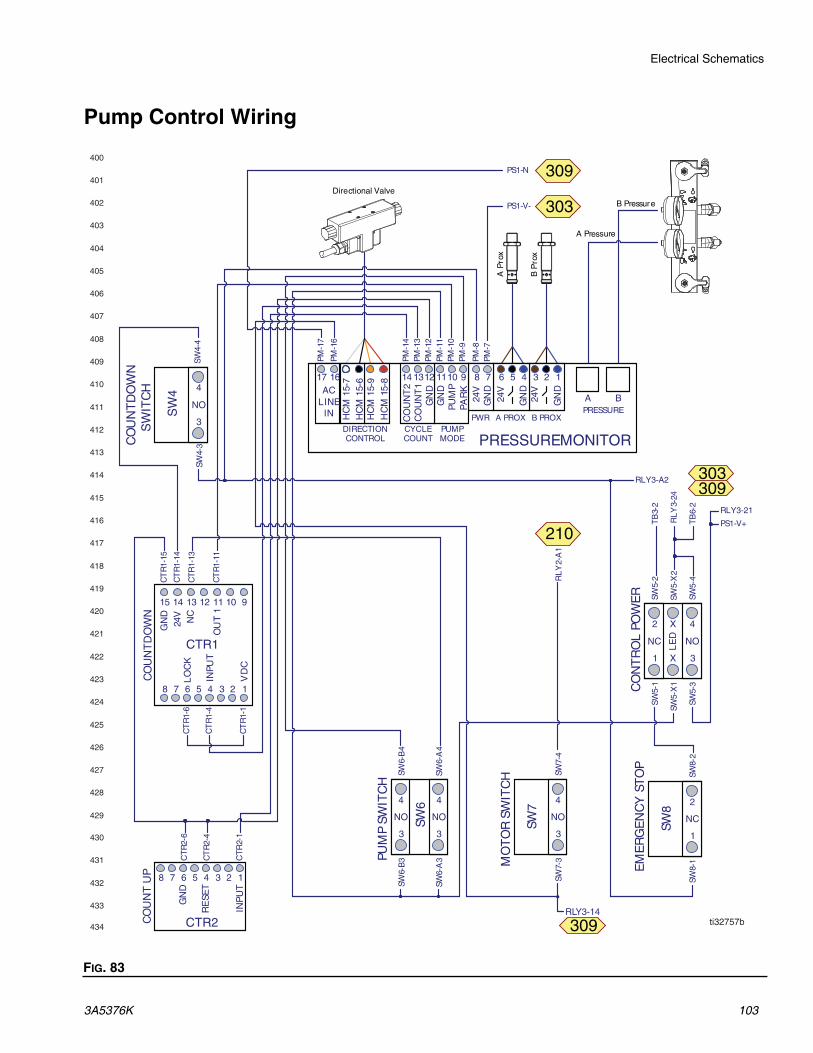
Electrical Schematics
3A5376K 103
Pump Control Wiring
FIG. 83
ti32757bRLY3-14
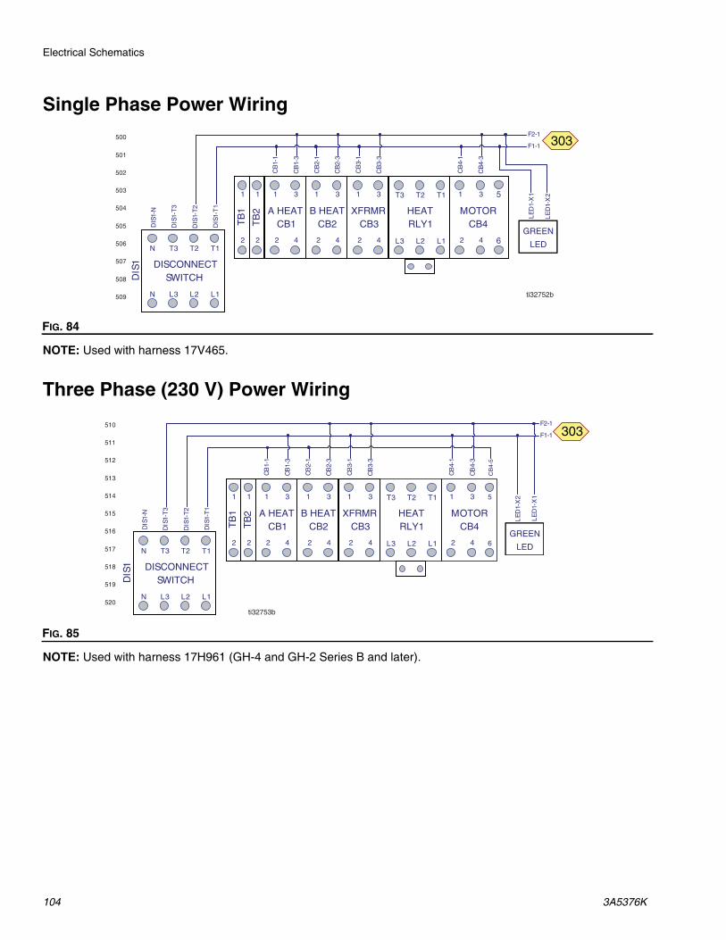
Electrical Schematics
104 3A5376K
Single Phase Power Wiring
NOTE: Used with harness 17V465.
Three Phase (230 V) Power Wiring
NOTE: Used with harness 17H961 (GH-4 and GH-2 Series B and later).
FIG. 84
FIG. 85
ti32752b
5
6
ti32753b
5
6
CB
4-5

Electrical Schematics
3A5376K 105
GH-2 Three Phase (400 V) Power Wiring
NOTE: Used with harness 17V736.
GH-4 Three Phase (400 V) Power Wiring
NOTE: Used with harness 17H960.
FIG. 86
FIG. 87
ti32754b
5
6
ti36996a
5
6
CB
4-5
531
532
533
534
535
536
537
538
539
540

Dimensions
106 3A5376K
Dimensions10
.78
in(2
74 m
m)
4.1in(104 mm) 19
in(4
83 m
m)
20.8
8 in
(530
mm
)
20.75 in(527 mm)ID .438 in
(11 mm)
ID .438 in(11 mm)
ID .750 in(19 mm)
54.0
0 in
(137
1.6
mm
)
1.70 in(43 mm)
22.25 in(565 mm)
32.96 in(837 mm)

Dimensions
3A5376K 107

Technical Specifications
108 3A5376K
Technical Specifications
Gusmer Hydraulic ProportionerUS Metric
Maximum Fluid Working Pressure for Bare ProportionersGH-2
2000 psi 13.8 MPa, 138 barGH-4Minimum Fluid Working Pressure for Bare ProportionersGH-2
700 psi 4.8 MPa, 48 barGH-4Fluid : Oil Pressure RatioGH-2 1.64 : 1GH-4 1.91 : 1Fluid Inlets
Component A (ISO) 3/4 npt(f), 300 psi maximum 3/4 npt(f), 2.07 MPa, 20.7 bar maximum
Component B (RES) 3/4 npt(f), 300 psi maximum 3/4 npt(f), 2.07 MPa, 20.7 bar maximum
Fluid OutletsComponent A (ISO) #8 1/2 in. JIC, with #5 5/16 JIC adapterComponent B (RES) #10 5/8 in. JIC, with #6 3/8 in. JIC adapterFluid Circulation Ports1/4 npsm(m) 250 psi 1.75 MPa, 17.5 barMaximum Fluid Temperature
190°F 88°CMaximum Output (10 weight oil at ambient temperature)GH-2 28 lb/min (60 Hz) 13 kg/min (60 Hz)GH-4 45 lb/min (60 Hz) 20 kg/min (60 Hz)Output per Cycle (A and B)GH-2 0.074 gal. 0.28 literGH-4 0.063 gal. 0.24 literSupply Voltage Tolerance230 V nominal, 1 phase 200-240 V, 50/60 Hz230 V nominal, 3 phase 200-240 V, 50/60 Hz400 V nominal, 3 phase 350-415 V, 50/60 Hz
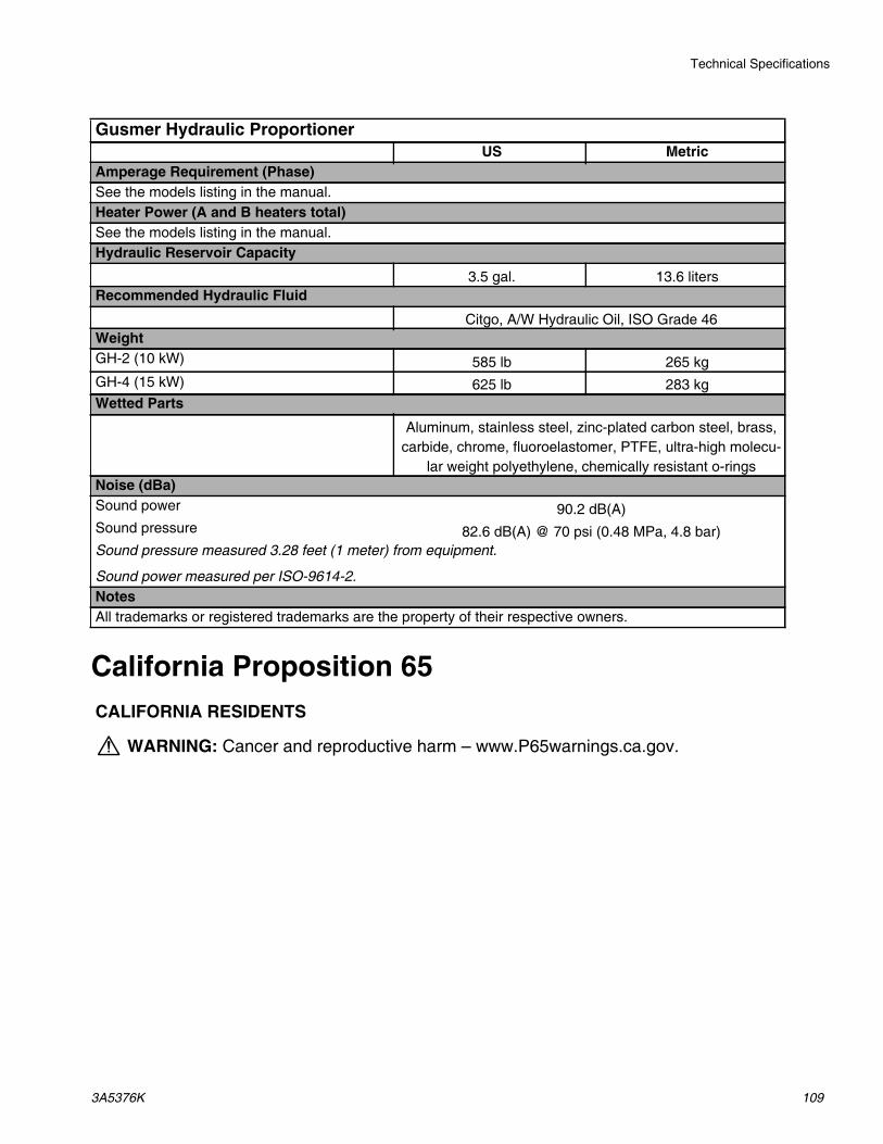
Technical Specifications
3A5376K 109
California Proposition 65
Amperage Requirement (Phase)See the models listing in the manual.Heater Power (A and B heaters total)See the models listing in the manual.Hydraulic Reservoir Capacity
3.5 gal. 13.6 litersRecommended Hydraulic Fluid
Citgo, A/W Hydraulic Oil, ISO Grade 46WeightGH-2 (10 kW) 585 lb 265 kgGH-4 (15 kW) 625 lb 283 kgWetted Parts
Aluminum, stainless steel, zinc-plated carbon steel, brass, carbide, chrome, fluoroelastomer, PTFE, ultra-high molecu-
lar weight polyethylene, chemically resistant o-ringsNoise (dBa)Sound power 90.2 dB(A)Sound pressure 82.6 dB(A) @ 70 psi (0.48 MPa, 4.8 bar)Sound pressure measured 3.28 feet (1 meter) from equipment.
Sound power measured per ISO-9614-2.NotesAll trademarks or registered trademarks are the property of their respective owners.
CALIFORNIA RESIDENTS
WARNING: Cancer and reproductive harm – www.P65warnings.ca.gov.
Gusmer Hydraulic ProportionerUS Metric

All written and visual data contained in this document reflects the latest product information available at the time of publication. Graco reserves the right to make changes at any time without notice.
Original instructions. This manual contains English. MM 3A5376Graco Headquarters: Minneapolis
International Offices: Belgium, China, Japan, Korea
GRACO INC. AND SUBSIDIARIES • P.O. BOX 1441 • MINNEAPOLIS MN 55440-1441 • USACopyright 2020, Graco Inc. All Graco manufacturing locations are registered to ISO 9001.
www.graco.comRevision K, June 2020
Graco Extended WarrantyGraco warrants all equipment referenced in this document which is manufactured by Graco and bearing its name to be free from defects in material and workmanship on the date of sale to the original purchaser for use. Graco will, for a period as defined in the table below from the date of sale, repair or replace any part of the equipment determined by Graco to be defective. This warranty applies only when the equipment is installed, operated and maintained in accordance with Graco’s written recommendations.
This warranty does not cover, and Graco shall not be liable for general wear and tear, or any malfunction, damage or wear caused by faulty installation, misapplication, abrasion, corrosion, inadequate or improper maintenance, negligence, accident, tampering, or substitution of non-Graco component parts. Nor shall Graco be liable for malfunction, damage or wear caused by the incompatibility of Graco equipment with structures, accessories, equipment or materials not supplied by Graco, or the improper design, manufacture, installation, operation or maintenance of structures, accessories, equipment or materials not supplied by Graco.
This warranty is conditioned upon the prepaid return of the equipment claimed to be defective to an authorized Graco distributor for verification of the claimed defect. If the claimed defect is verified, Graco will repair or replace free of charge any defective parts. The equipment will be returned to the original purchaser transportation prepaid. If inspection of the equipment does not disclose any defect in material or workmanship, repairs will be made at a reasonable charge, which charges may include the costs of parts, labor, and transportation.
THIS WARRANTY IS EXCLUSIVE, AND IS IN LIEU OF ANY OTHER WARRANTIES, EXPRESS OR IMPLIED, INCLUDING BUT NOT LIMITED TO WARRANTY OF MERCHANTABILITY OR WARRANTY OF FITNESS FOR A PARTICULAR PURPOSE.
Graco’s sole obligation and buyer’s sole remedy for any breach of warranty shall be as set forth above. The buyer agrees that no other remedy (including, but not limited to, incidental or consequential damages for lost profits, lost sales, injury to person or property, or any other incidental or consequential loss) shall be available. Any action for breach of warranty must be brought within two (2) years of the date of sale.
GRACO MAKES NO WARRANTY, AND DISCLAIMS ALL IMPLIED WARRANTIES OF MERCHANTABILITY AND FITNESS FOR A PARTICULAR PURPOSE, IN CONNECTION WITH ACCESSORIES, EQUIPMENT, MATERIALS OR COMPONENTS SOLD BUT NOT MANUFACTURED BY GRACO.
These items sold, but not manufactured by Graco (such as electric motors, switches, hose, etc.), are subject to the warranty, if any, of their manufacturer. Graco will provide purchaser with reasonable assistance in making any claim for breach of these warranties.
In no event will Graco be liable for indirect, incidental, special or consequential damages resulting from Graco supplying equipment hereunder, or the furnishing, performance, or use of any products or other goods sold hereto, whether due to a breach of contract, breach of warranty, the negligence of Graco, or otherwise.
FOR GRACO CANADA CUSTOMERSThe Parties acknowledge that they have required that the present document, as well as all documents, notices and legal proceedings entered into, given or instituted pursuant hereto or relating directly or indirectly hereto, be drawn up in English. Les parties reconnaissent avoir convenu que la rédaction du présente document sera en Anglais, ainsi que tous documents, avis et procédures judiciaires exécutés, donnés ou intentés, à la suite de ou en rapport, directement ou indirectement, avec les procédures concernées.
Graco InformationFor the latest information about Graco products, visit www.graco.com.For patent information, see www.graco.com/patents.TO PLACE AN ORDER, contact your Graco distributor or call to identify the nearest distributor.
Phone: 612-623-6921 or Toll Free: 1-800-328-0211, Fax: 612-378-3505
Part Description Warranty Period
17U244 Pressure Monitor Kit 120 Months (10 Years)
All Other Parts 12 Months