Guidelines on Standard Formats and Data …wgiss.ceos.org/archive/archive.doc/Format...
137
CEOS Guidelines on Standard Formats and Data Description Languages Page i of vi CEOS.WGISS.DS.TN01 Issue 1.0 May 1998 CEOS Working Group on Information Systems and Services Data Subgroup Guidelines on Standard Formats and Data Description Languages Version 1.0 FormGuid.doc
Transcript of Guidelines on Standard Formats and Data …wgiss.ceos.org/archive/archive.doc/Format...
CEOS Guidelines on Standard Formats and Data Description Languages Page i of viCEOS.WGISS.DS.TN01 Issue 1.0 May 1998
CEOSWorking Group on Information Systems and Services
Data Subgroup
Guidelines on Standard Formats and Data Description Languages
Version 1.0
Doc. Ref.: CEOS.WGISS.DS.TN01Date: 18 May 1998Issue: 1.0
FormGuid.doc

CEOS Guidelines on Standard Formats and Data Description Languages Page ii of viCEOS.WGISS.DS.TN01 Issue 1.0 May 1998
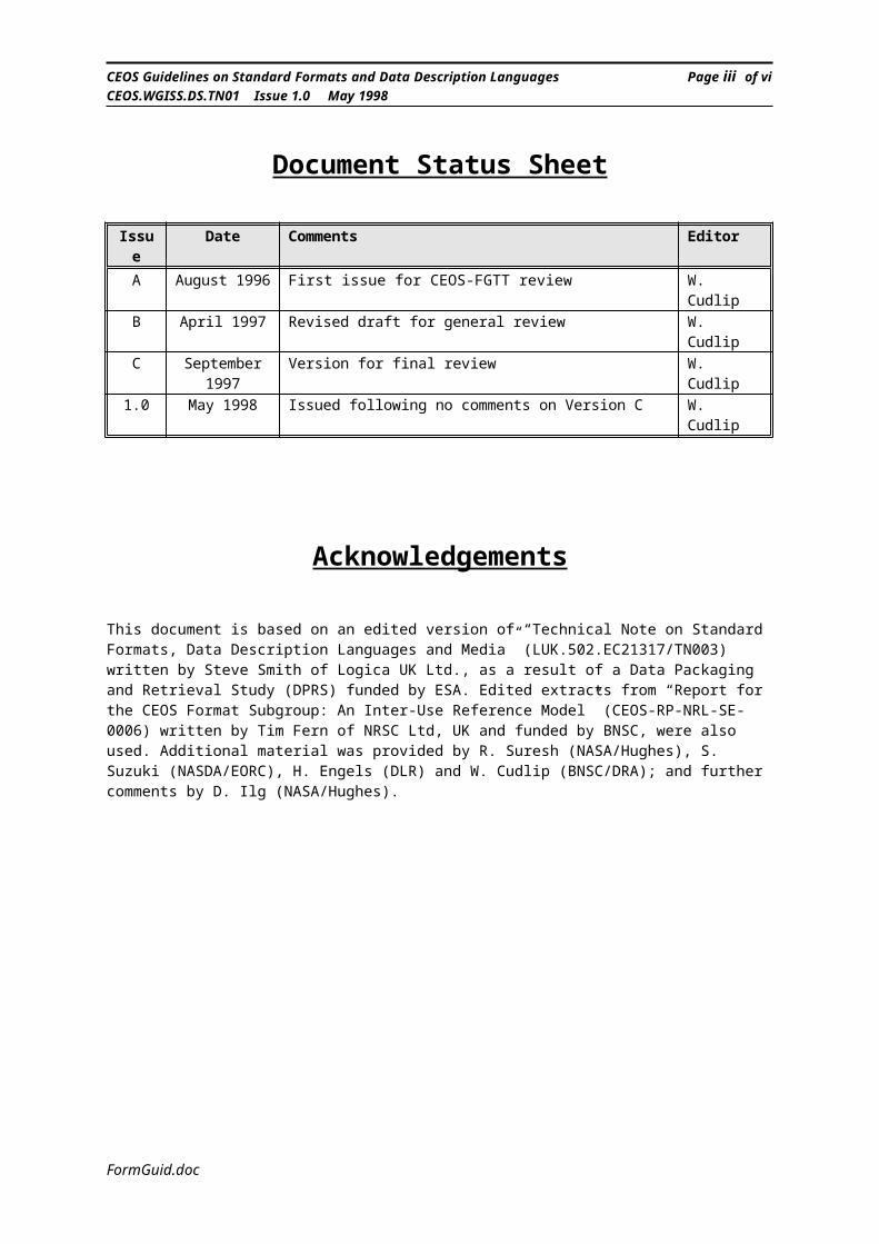
Document Status Sheet
Issue Date Comments EditorA August 1996 First issue for CEOS-FGTT review W. CudlipB April 1997 Revised draft for general review W. CudlipC September 1997 Version for final review W. Cudlip
1.0 May 1998 Issued following no comments on Version C W. Cudlip
Acknowledgements
This document is based on an edited version of “Technical Note on Standard Formats, Data Description Languages and Media” (LUK.502.EC21317/TN003) written by Steve Smith of Logica UK Ltd., as a result of a Data Packaging and Retrieval Study (DPRS) funded by ESA. Edited extracts from “Report for the CEOS Format Subgroup: An Inter-Use Reference Model” (CEOS-RP-NRL-SE-0006) written by Tim Fern of NRSC Ltd, UK and funded by BNSC, were also used. Additional material was provided by R. Suresh (NASA/Hughes), S. Suzuki (NASDA/EORC), H. Engels (DLR) and W. Cudlip (BNSC/DRA); and further comments by D. Ilg (NASA/Hughes).
FormGuid.doc
CEOS Guidelines on Standard Formats and Data Description Languages Page iii of viCEOS.WGISS.DS.TN01 Issue 1.0 May 1998
CONTENTSSections Page
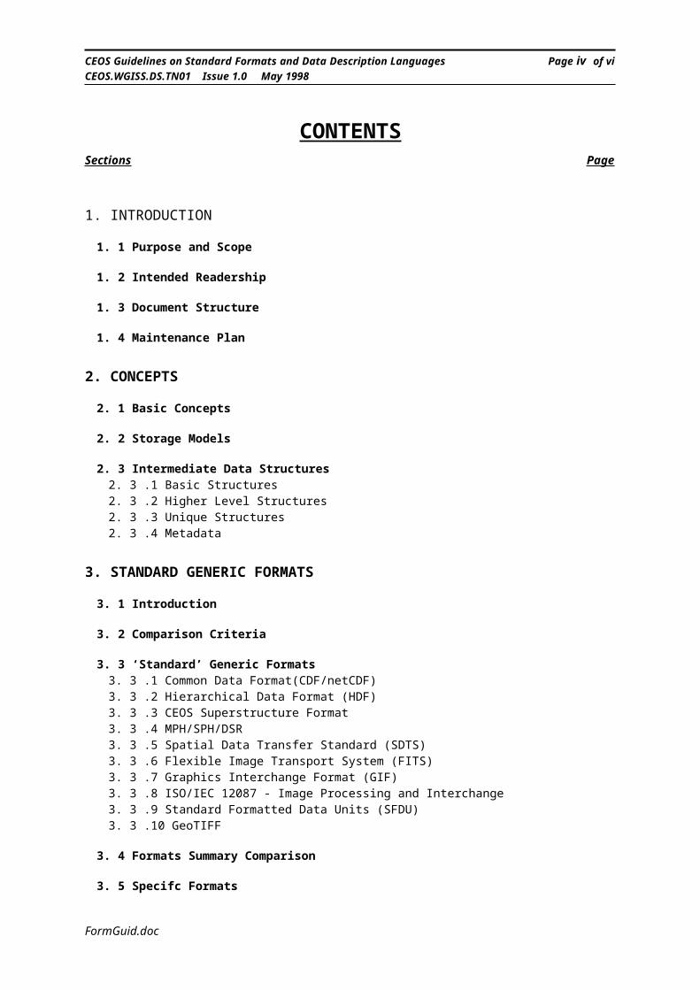
1. INTRODUCTION
1. 1 Purpose and Scope
1. 2 Intended Readership
1. 3 Document Structure
1. 4 Maintenance Plan
2. CONCEPTS
2. 1 Basic Concepts
2. 2 Storage Models
2. 3 Intermediate Data Structures2. 3 .1 Basic Structures2. 3 .2 Higher Level Structures2. 3 .3 Unique Structures2. 3 .4 Metadata
3. STANDARD GENERIC FORMATS
3. 1 Introduction
3. 2 Comparison Criteria
3. 3 ‘Standard’ Generic Formats3. 3 .1 Common Data Format(CDF/netCDF)3. 3 .2 Hierarchical Data Format (HDF)3. 3 .3 CEOS Superstructure Format3. 3 .4 MPH/SPH/DSR3. 3 .5 Spatial Data Transfer Standard (SDTS)3. 3 .6 Flexible Image Transport System (FITS)3. 3 .7 Graphics Interchange Format (GIF)3. 3 .8 ISO/IEC 12087 - Image Processing and Interchange3. 3 .9 Standard Formatted Data Units (SFDU)3. 3 .10 GeoTIFF
3. 4 Formats Summary Comparison
3. 5 Specifc Formats
4. DATA DESCRIPTION LANGUAGES
4. 1 Introduction
4. 2 ‘Standard’ DDLs
FormGuid.doc
CEOS Guidelines on Standard Formats and Data Description Languages Page iv of viCEOS.WGISS.DS.TN01 Issue 1.0 May 1998
4. 2 .1 FREEFORM4. 2 .2 EAST - Enhanced Ada SubSet4. 2 .3 MADEL - Modified ASN.1 as a Data Description Language4. 2 .4 PVL - Parameter Value Language4. 2 .5 DEDSL - Data Entity Dictionary Specification Language4. 2 .6 EXPRESS
4. 3 DDL Summary Comparison
5. ADDITIONAL INFORMATION
5. 1 Heirarchical Data Format (HDF)5. 1 .1 Introduction5. 1 .2 Scientific Data Set (SDS)5. 1 .3 HDF Vset5. 1 .4 Software Tools5. 1 .5 HDF Advantages
5. 2 CEOS SAR Formats
6. OTHER ASPECTS
6. 1 Format Translation
7. CONCLUSIONS AND RECOMMENDATIONS
APPENDIX A. REFERENCES 87
APPENDIX B. ACRONYMS 89
APPENDIX C. REVISION HISTORY 92
FormGuid.doc
CEOS Guidelines on Standard Formats and Data Description Languages Page v of viCEOS.WGISS.DS.TN01 Issue 1.0 May 1998
Figures and TablesFigures Page
Figure 2-1- Reference Model - Basic Concept_____________________________________________________Figure 2-2: An Example of a Multi-dimensional Array______________________________________________Figure 2-3: An 8-bit Image____________________________________________________________________Figure 2-4: Three Types of 24-bit Images_________________________________________________________Figure 2-5: An Example of a Palette____________________________________________________________Figure 2-6: A Ragged Array___________________________________________________________________Figure 2-7: A 3x3 Array of Records_____________________________________________________________Figure 2-8: A table as an Array of Records_______________________________________________________Figure 2-9: An Index Structure_________________________________________________________________Figure 2-10: A Representation of a Point Data Set_________________________________________________Figure 2-11: A Swath________________________________________________________________________Figure 2-12: A “Label = Value” Metadata Structure_______________________________________________Figure 3-1: An Example organisation of Data Objects in an HDF File_________________________________Figure 3-2: The Software Interface of a HDF File__________________________________________________Figure 3-3: Schematic of the CEOS Superstructure Format__________________________________________Figure 3-4: Schematic of an MPH/SPH/DSR Formatted File_________________________________________Figure 3-5: Examples of MPH/SPH/DSR Media Format_____________________________________________Figure 3-6: Sample FITS Image File____________________________________________________________Figure 3-7: Schematic of a GIF File_____________________________________________________________Figure 3-8: Interfaces Between the Parts of the ISO 12087 Standard___________________________________Figure 3-9: Overall Structure of the IIF-DF File___________________________________________________Figure 3-10: An SFDU Label-Value-Object (LVO)_________________________________________________Figure 3-11: An SFDU Packaged Data Product___________________________________________________Figure 4-1: A Sample MADEL Description_______________________________________________________Figure 4-2: A Sample PVL Listing______________________________________________________________Figure 4-3: An Example of the use of the DEDSL__________________________________________________Figure 4-4: An Example of the use of EXPRESS___________________________________________________Figure 5-1: A 3-dimensional Multi-dimensional array with dimensions 4 by 3 by 9________________________Figure 5-2: Diagram of Pathfinder AVHRR Land Data product showing 4 of the 12 layers_________________Figure 5-3: A Raster Image____________________________________________________________________Figure 5-4: NSIDC SSM/I Data Product_________________________________________________________Figure 5-5: Data organization in V Group and UNIX file system______________________________________ Tables Page
Table 3-1: Standard Formats Comparison________________________________________________________Table 3-2: Illustrative Systems using Standard Formats_____________________________________________Table 4-1: Data Description Language Comparison________________________________________________Table 5-1: HDF Utilities______________________________________________________________________Table 5-2: NCSA Tools_______________________________________________________________________Table 5-3: Other Public Domain Tools___________________________________________________________Table 5-4: Commercial Tools__________________________________________________________________Table 5-5: CEOS Format File Structure Overview_________________________________________________
-------- ------
FormGuid.doc

CEOS Guidelines on Standard Formats and Data Description Languages Page vi of viCEOS.WGISS.DS.TN01 Issue 1.0 May 1998
Blank Page
FormGuid.doc
CEOS Guidelines on Standard Formats and Data Description Languages Page 1 of 92CEOS.WGISS.DS.TN01 Issue 1.0 May 1998
1. Introduction
1.1 Purpose and ScopeEarth Observation data are currently available in a range of different formats and there is a strong desire to standardise how such data are presented in order to improve the efficiency with which the data are handled and processed. However, format systems have different characteristics and a single format standard is not capable of satisfying all formatting needs. It has to be accepted that a number of formatting systems will be used by different agencies and different organisations for the foreseeable future.
The role of CEOS is to try to prevent the needless proliferation of format systems, encourage standardisation where possible, and ensure that format systems are developed in such a way that format translation can be performed easily, if required.
This document provides an analysis and critique of a number of standard formatting techniques that are applicable for the formatting and delivery of digital data. It also provides an analysis of current data description techniques. It is hoped that this document provides a sufficient level of detail for an application engineer to made a decision as to which technique is most appropriate for the application in hand. Links to further information are given wherever possible.
The document does not attempt to cover all formats used for scientific data sets. It concentrates on those formats which are, or are likely to be, used for Earth Observation data.
Note: This document is based on an analysis performed in the first quarter of 1995 and reviewed in late 1996 and mid 1997. It is planned that this document should be considered an evolving one with update sufficiently frequent to reflect the current situation. However, the rapid pace of developments in this field means the document cannot be guaranteed to be fully up-to-date and it is recommended that the provided WWW links be investigated to obtain the latest information.
1.2 Intended ReadershipThe intended readership of this report is anyone that must make a decision of which particular formatting technique or data description should be used for a particular application. It is intended that this report will provide enough detail for an engineer to make a reasonable analysis and reach a decision without having to obtain the full reference material for all the various techniques. Further details can be obtained from the reference documents, of which contact information is provided for each technique discussed.
The document should also be of use to users of data who wish to understand the characteristics of the particular format used for supplied data.
FormGuid.doc
CEOS Guidelines on Standard Formats and Data Description Languages Page 2 of 92CEOS.WGISS.DS.TN01 Issue 1.0 May 1998
1.3 Document StructureIn summary, the document is structured as follows: Section 2 describes the basic concepts needed to understand the
following sections; Section 3 provides an analysis of the various Standard Data Formats
available; Section 4 provides an analysis of the various Data Description
Languages available; Section 5 discusses other aspects related to format systems; Section 6 gives additional information on the two major format
systems Section 7 gives the conclusions and recommendations
1.4 Maintenance Plan
It is intended that this document should be reviewed and updated at least annually. Early in its existence more frequent revisions may be warranted. The revisions will be carried out by members of the CEOS Format Guidelines Task Team although specific experts may be called upon to review particular sections.
The first official CEOS version will be V1.0. Subsequent minor revisions will increment the number after the decimal point (e.g., 1.1, 1.2, etc.). Major revisions will increment the first digit (e.g., 2.0, 3.0, etc.). Details of the revision history are given in Appendix C.
FormGuid.doc
CEOS Guidelines on Standard Formats and Data Description Languages Page 3 of 92CEOS.WGISS.DS.TN01 Issue 1.0 May 1998
2. Concepts
2.1 Basic ConceptsThis is an introduction to the basic concepts of a reference model which is useful to have in mind when evaluating the format systems and data description languages described in later sections. This text is extracted from “Data Inter-Use Reference Model” [40].
The following diagram (Figure 2.1) and text describe the entities and groups that facilitate the exchange of information. It is a deliberate attempt to abstract the problem to simple basic concepts.
Figure 2-1- Reference Model - Basic Concept
Use Word 6.0c or later to
view Macintosh picture.
FormGuid.doc
CEOS Guidelines on Standard Formats and Data Description Languages Page 4 of 92CEOS.WGISS.DS.TN01 Issue 1.0 May 1998
Values
These are the actual data values (bits and bytes) that correspond to the measurements and associated data. It is the unique aspect of a data set that differentiates it from every other data set. Traditionally delivered in an operating system file or tape file.
Storage Structure
This is the focus of traditional format standardisation approach, e.g. CEOS format (in particular, the CEOS product descriptions rather than the media (CCT) related descriptions). This is the structure of the data set that allows values for each field to be located and interpreted.
Traditionally delivered as a User Guide, international standard or occasionally as “self describing data,” and tends to describe basic numerical representations (i.e. IEEE float, integers, etc.).
Meaning
This is the information that the values represent, i.e. how to interpret the values as information. Traditionally delivered as a User Guide or as separate reference information.
Data Package
This is the combination of Meaning, Structure and Values. There is no implication that these three components arrive simultaneously or in the same file, but without all three, information is not transferred. All components are required to effect use of the data. All three must be provided by a data supplier to enable Inter-use of the data by the user of data sets.
Data Packages are traditionally delivered as separate fragments (i.e., they do not contain all the information needed to completely understand the data set, particularly with regard to semantic information).
The mechanics of delivery are separate from what needs to be delivered, The following describes those components.
Delivery Unit
This a single delivery of data or information, e.g. a tape, E-Mail, etc.
Delivery Packet
This is simply the segmentation of a Delivery Unit into manageable lumps for transfer, which are reassembled on arrival, e.g. a file, network packet, etc.
The two delivery concepts are introduced here to contrast and exclude them from the discussion. A delivery mechanism should transport a Data Package, part of a Data Package or several Data Packages securely and faithfully without affecting or having to understand the data.
FormGuid.doc
CEOS Guidelines on Standard Formats and Data Description Languages Page 5 of 92CEOS.WGISS.DS.TN01 Issue 1.0 May 1998
2.2 Storage ModelsUltimately, most information is stored in bytes in a linear memory addressing model. All current commercial computer systems use this model for storage in memory and on media.
A linear memory model is where memory resources are managed as one sequence of memory units (i.e. bytes). Even arrays which are multidimensional entities are stored as a linear sequence, with an addressing calculation which takes the co-ordinates and converts them into a linear address location.
Since this model is so standard , Data Description Languages (DDLs) effectively assume that all descriptions are ones of mapping information entities to the underlying linear memory model.
The purpose of DDLs is to provide an OPEN standard for data access (i.e. one not dependent of a particular machine or software tool). In this way the writer of data and the reader of data can be separate systems.
By contrast, a CLOSED data access mechanism is one where the writer and reader use the same system. For instance, all third generation computer languages hide the data organisation from the user, so in Ada the user is not aware how an array is actually arranged, but can write and recover a piece of information using its co-ordinates. The entry point to data access has changed from the bits and bytes to the utilities that access them.
The HDF format system is a closed data access mechanisms since only HDF utilities can create and access the data values.
It seems that for information inter-operation an Open system is required, however, there is a competing approach, that is to expand a closed system until all the participants are included. The difficulties of this second approach (mainly, achieving a mutually agreed standard) are what cause DDLs to be needed.
However, the Internet and more specifically the World Wide Web in effect are providing a common ‘programming’ environment where the heterogeneity of the member systems is hidden under a common programming approach.
This means that an alternative storage model can now be considered, where providers and users construct, not descriptions, but access utilities (or applets) to data. This can then be thought of as open access to closed access mechanisms, in that the readers and writers of data are constructed at the same time under the same system, but the user has access to those accessors (which encapsulate the memory model of the data being used).
FormGuid.doc
CEOS Guidelines on Standard Formats and Data Description Languages Page 6 of 92CEOS.WGISS.DS.TN01 Issue 1.0 May 1998
To summarise, there are two forms of storage model:
• Linear memory model (MSB first, or last).
• Shared Access Utility model
In developing a formatting system to facilitate the inter-operation of Information and data, both should be considered. The first provides the most flexibility and only requires descriptions to be constructed for a data set type to become a member of the system; the second is exemplified in the guise of the WWW, where there common open access is provided but the underlying format is hidden.
In both cases, the principle is to provisionally leave the data in its native form and provide an additional description/accessor that makes the data accessible to other users. It then becomes a matter of operational choice whether the access is performed on the fly (real time) as and when the data is required; or a part of a system format translation programme.
FormGuid.doc
CEOS Guidelines on Standard Formats and Data Description Languages Page 7 of 92CEOS.WGISS.DS.TN01 Issue 1.0 May 1998
2.3 Intermediate Data Structures
A data structure study has been carried out by the EOSDIS project to identify and define common data structures necessary to support EOS and other Earth science data products; to begin to develop Application Programming Interfaces (APIs) to such common data structures; and to develop or use existing Hierarchical Data Format (HDF) interfaces to implement these APIs. This activity has helped to identify data structures commonly used by science groups, standardize and promulgate those structures, and provide common utilities to support them. As data products are implemented, the data structures and science conventions that are used in building the product will be analyzed and incorporated into the development of a complete standard data model.
As a result of the EOSDIS project’s initial data format evaluation, it was recognized that a continuing survey of data structures required by the EOS science community was needed. An initial survey of selected Version 0 Data Products to be generated by DAACs was conducted. A list of data structures was compiled based on data models developed for these data products and from other sources. The descriptions of these data structures for selected data products are described in “EOSDIS V0 FY 92 Data Structures Report.” Some additional structures have been defined since the study. The list now contains the following structures:
Basic structures:• Multi-dimensional Array• Image• Palette• Ragged Array• Array of Records• Index Structure• Collection of Structures• Topological Structure• Text Structure• Document Structure• Metadata
High level structures:• Point Data• Gridded Data• Swath Data
Unique structures Metadata
For the EOSDIS Core System (ECS), the follow-on to V0, this list has been further refined into the “Data Type Taxonomy.” The Taxonomy can be found through the ECS Data Handling System (EDHS) at: http://edhs1.gsfc.nasa.gov/
FormGuid.doc

CEOS Guidelines on Standard Formats and Data Description Languages Page 8 of 92CEOS.WGISS.DS.TN01 Issue 1.0 May 1998
2.3.1 Basic Structures
A basic conceptual structure is intended to be a simple data structure that has wide ranging applicability to many science disciplines. These structures can serve as the building blocks from which more complex discipline-specific or instrument-specific structures can be built.
This section will provide a conceptual understanding of the basic structures which were listed in the previous section. It is assumed that data format systems will evolve to provide explicit software support for all structures described below.
Multi-dimensional Array Multi-dimensional arrays are n-dimensional arrays of homogenous data. Each array contains only one data type and size. All but one dimension are fixed length. This structure can be used for sensor data. Processing data can be stored in a binary table which is an instantiation of the Multi-dimensional array. The Multi-dimensional array might support the equal angle grid and sparse matrices. Examples of data types that can be stored in the Multi-dimensional array are integers of 8, 16, or 32 bits, and floating point numbers of 32 or 64 bits, and possibly n bit integers where n is not a multiple of 8. Figure 2-2 is an example of an n-dimensional array where n= 3. The Multi-dimensional array is not limited to three dimensions. Multi-dimensional arrays may be defined with their dimensions in any order to optimize the storage for a certain method of access or to emulate any style of interleaving (BSQ, BIP, BIL)
Figure 2-2: An Example of a Multi-dimensional ArrayUse Word 6.0c or later to
view Macintosh picture.
FormGuid.doc
CEOS Guidelines on Standard Formats and Data Description Languages Page 9 of 92CEOS.WGISS.DS.TN01 Issue 1.0 May 1998
Image An image is a two dimensional array of spatially organized measurements. Images typically contain 8- or 24-bit pixels. Image data may contain bands in different spectral wavelengths. Figures 2-3 and 2-4 give examples of image structures. An 8-bit image is generally associated with a palette (Figure 2-5).
Figure 2-3: An 8-bit ImageUse Word 6.0c or later to
view Macintosh p icture.
Figure 2-4: Three Types of 24-bit Images
Use Word 6.0c or later to
view Macintosh picture.
Palette A palette consists of an 8 bit lookup table which associates a color with each of 256 possible pixel values which can be stored in an 8 bit image.
Figure 2-5: An Example of a Palette
Use Word 6.0c or later to
view Macintosh picture.
Ragged Array A ragged array is a multidimensional array for storage of homogenous binary data with variable length along one direction. A row may contain multiple
FormGuid.doc

CEOS Guidelines on Standard Formats and Data Description Languages Page 10 of 92CEOS.WGISS.DS.TN01 Issue 1.0 May 1998
science elements of the same data type and size. This structure supports the equal area grid. Examples of data types that can be stored in the ragged array are integers of 8, 16, or 32 bits, and floating point numbers of 32 or 64 bits, and possibly n-bit integers where n is not a multiple of 8. Figure 2-6 shows an example of a 2 dimensional ragged array with the variable length dimension shown horizontally.
Figure 2-6: A Ragged ArrayUse Word 6.0c or later to
view Macintosh picture.
Data may be interleaved in any way, including the standard options: by plane (band), row (line), or science element (pixel).
Array of Records An array of records is a multi-dimensional array for storage of heterogeneous binary data. An array of records may contain character, integer and floating point data (e.g., Figure 2-7). This structure may support point data.
Figure 2-7: A 3x3 Array of RecordsUse Word 6.0c or later to
view Macintosh picture.
Table A table is a one-dimensional instantiation of the array of records, in which a row defines a heterogeneous structure (Figure 2-8). Each column can be of any allowable data type. Example: spreadsheets.
FormGuid.doc
CEOS Guidelines on Standard Formats and Data Description Languages Page 11 of 92CEOS.WGISS.DS.TN01 Issue 1.0 May 1998
Figure 2-8: A table as an Array of RecordsUse Word 6.0c or later to
view Macintosh picture.
Index Structure An index structure consists of a table for indexing location and other information pertaining to the science data. This structure may be used to support point data.
Figure 2-9: An Index StructureUse Word 6.0c or later to
view Macintosh picture.
Collection of Structures The collection of structures provides a method of grouping related data structures together in a similar way to mathematical sets.
Topological Structure Topological structures mostly include vector structures and will not be further discussed in this document.
Text Structure Text structure refers to ASCII text storage for simple documentation.
Document Structure Document structure refers to formatting text plus graphics and other special formatting information for documentation.
FormGuid.doc

CEOS Guidelines on Standard Formats and Data Description Languages Page 12 of 92CEOS.WGISS.DS.TN01 Issue 1.0 May 1998
2.3.2 Higher Level Structures
Higher level structures are pre-defined aggregates of basic structures which are probably unique to Earth science applications. This section will describe the higher level structures referred to in this document.
Point Data Point data is data that is generally made up of records and fields, with some set of those fields constituting a point location. The fields can be simple values of any type including pointers. The location fields, taken together can be considered, as the “location record.” If a point is located in N-space, there are N fields in the location record.
Figure 2-10: A Representation of a Point Data Set
Use Word 6.0c or later to
view Macintosh picture.
Point data may be a result of large scale field programs like ISLSCP, or data collected routinely by ships, buoys, and balloons. These types of data are called by various names by different users. Here the term “point data” is used to refer to data that is often called station data, correlative data, in situ data, ground truth data, field data, etcetera.
FormGuid.doc

CEOS Guidelines on Standard Formats and Data Description Languages Page 13 of 92CEOS.WGISS.DS.TN01 Issue 1.0 May 1998
Gridded Data Gridding is a scheme for dividing the Earth or a projection of the Earth into many small bins or cells. Each bin has a unique corresponding spatial location with respect to the Earth and any number of data values associated with that point or area. Data that are organized into a grid is considered gridded data. Two basic types of gridded data commonly used for Earth science data are equal-angle and equal-area.
Equal-angle grids contain data that are sampled at regular latitude/longitude intervals (e.g. Figure 2-11). They can be stored as simple rectangular arrays and are, therefore, easily manipulable.
Equal-area grids contain data that are organized such that each data point represents a constant area on the surface of the Earth. They can result in irregular arrays or regular arrays with significant null data.
Figure 2-11: An Equal-Angle GridUse Word 6.0c or later to
view Macintosh picture.
Figure 2-12: An Equal-Area GridUse Word 6.0c or later to
view Macintosh picture.
FormGuid.doc

CEOS Guidelines on Standard Formats and Data Description Languages Page 14 of 92CEOS.WGISS.DS.TN01 Issue 1.0 May 1998
Swath Data Swath data is best described by examining a common scenario in which it arises. It is most often produced by an orbiting scanning sensor which has a set of detectors scanning in the cross-track direction. The motion of the satellite (by definition, in the along-track direction) causes the footprint of the data to form a “ribbon” centered on the sub-nadir track. In the case of polar orbiting satellites, this ribbon will continually wrap around the Earth from pole-to-pole.
Figure 2-11: A Swath
Use Word 6.0c or later to
view Macintosh picture.
FormGuid.doc

CEOS Guidelines on Standard Formats and Data Description Languages Page 15 of 92CEOS.WGISS.DS.TN01 Issue 1.0 May 1998
2.3.3 Unique Structures
A unique data structure is defined as any structure which does not directly correspond to any of the standard structures defined in this document and is not likely to be useful over a wide range of applications. Because of the narrow scope of such data structures, they must be handled on a case-by-case basis. It is felt that all unique structures that will arise will be implementable through some combination of the basic structures described above.
2.3.4 Metadata
Most data products will contain some form of metadata. In most cases the metadata field descriptions vary from one product to another and from one producer to another. Most types of metadata can be supported in a “label = value” paradigm. In this widely-used paradigm, each metadata field is given a unique label and a value (or a list of values) of a datatype appropriate to the application. The necessary datatypes are integer, floating point, character, and string.
Metadata that does not fit the “label = value” paradigm (e.g., a matrix of coefficients) can be stored using an appropriate data structure from the list at the beginning of this section. Below is a “label = value” structure for a fictitious data set (Figure 2-14). For this example, the Consultative Committee for Space Data Systems’ (CCSDS) Parameter Value Language (PVL) has been used.
Figure 2-12: A “Label = Value” Metadata Structure
group = “General Info”;Data_Center_ID = “National Meteorological Information Center”;Dataset_ID = “JCT Surface Pressure”;Dataset_Description = “Surface atmospheric pressure derived from
satellite data.”;Sensor_Name = QSART;Investigator = “Bob Smith”;Temporal_Res = “Daily”;Spatial_X_Res = “1 Km”;Spatial_Y_Res = “1 Km”;Processing_Level = 4;Start_Date = “12 OCT 1994”;Stop_Date = “12 OCT 1994”;Parameter = (Pressure, Latitude, Longitude);Units = Mbars;Map_Projection = “Space Oblique Mercator”;
end_group = “general Info”;
FormGuid.doc
CEOS Guidelines on Standard Formats and Data Description Languages Page 16 of 92CEOS.WGISS.DS.TN01 Issue 1.0 May 1998
3. Standard Generic Formats
3.1 IntroductionThis section of the report analyses and discusses the available formatting and packaging techniques that could be used at the many stages of data processing, such as archiving, processing or delivery.
Essentially this section provides a rationale for the advantages, disadvantages and suitability of the various formatting techniques for particular tasks. Format systems vary greatly in their suitability for a particular task. For example, real-time processing versus archiving versus transmission efficiency. It is not anticipated that any one format or method would be ideal for all purposes and therefore end up being the one and only format in use for all applications.
3.2 Comparison CriteriaSo that the reader can easily compare the suitability of a particular formatting technique for a particular task, all the possible formats must be analysed against the same criteria. The following is a list of the primary criteria for analysis:
Data Description Information - as the integration of information systems grows larger, the number of formats in which users may receive data grows proportionally. Previously, documentation of the format of data products has been conveyed through conventional Interface Control Documents (ICDs) and Product Definition Documents (PDDs). This has lead to inconsistencies, language barriers and the potential loss of the data, as the documentation is incomplete. An aim of many recently developed formats is the inclusion of data description information, either embedded within the product or supplied separately by electronic means. For interoperability reasons and flexibility in product generation and use, it is essential that formats address this problem and supply coherent data description information in some manner.
Data Formatting or Packaging - the difference between these two aspects is very important and frequently overlooked in many data delivery systems. Within this report, Data Formatting is defined as the format of the individual elements of data, for example an image or an annotation attribute. It includes the syntax layout of the data and may also include the formatting of data that are related to each other, such as geo-location information with a particular image.Data Packaging defines the format process as applied at the higher level, that is, the packaging together of a number of products that have already been formatted some way, for delivery to the final user, data centre or a designated drop-off point. For example, this may include a number of images, each with an associated palette, the description information that describes the format of the images and the palettes. Particularly for a system that may have to deliver many different products as the result of a single query or order, this distinction becomes a most important one.For many formatting schemes the distinction between formatting and packaging is somewhat blurred.
Storage and Media Support - there are primarily two media types that we are concerned with, either sequential access media or random
FormGuid.doc
CEOS Guidelines on Standard Formats and Data Description Languages Page 17 of 92CEOS.WGISS.DS.TN01 Issue 1.0 May 1998
access media. Those standards that deal with the packaging of data often depend upon one of these particular types of media. The independence of the packaging format to the media can be of significance when designing systems that are to handle data into the future. It is not a good idea to select a packaging format that limits the media and technology that can be handled in the future. In particular, it is not a good idea to be limited to sequential media, since future technology is likely to continue to move toward random access capabilities.
Software Support - many formats’physical representations are complex to produce by the use of custom written software, particularly if a system has to handle a number of different formatting standards. The availability of software to support the formatting of data according to a particular standard, along with the software to read that data, greatly enhances the suitability of a format to many users. The extent of the software support for the different standards varies widely. This will be highlighted.
Long-term Stability - for many users selecting a standard format to use in the present day, the long-term stability of the standard does not seem of great importance, when compared to the usability, software support, widespread availability, etc. But for many space related data applications, it is important that the data that is archived now is still readable in 20 years time (or more). This implies that the standard that it is formatted to is of a stable nature. Furthermore, if a format is only specified through the use of a software library, then the likely evolution of the software must be considered. Long-term stability and support can be enhanced by a standard being published by a recognised international standards body. However,it must be recognised that a standard that exists only on paper from a standards body is open to interpretation each time it is implemented in software. Long-term stability does not come from simply writing things down. (Perhaps another word for stability is stagnation!)
FormGuid.doc
CEOS Guidelines on Standard Formats and Data Description Languages Page 18 of 92CEOS.WGISS.DS.TN01 Issue 1.0 May 1998
3.3 ‘Standard’ Generic Formats
3.3.1 Common Data Format(CDF/netCDF)
General The Common Data Format (CDF)[2] is developed and maintained by NASA. A variation of the format that was designed for transfer across networks was developed by Unidata and called Network Common Data Format (netCDF). The two formats are very similar except in the method that they used to physically encode data. There is a move to merge the two developments, but at this stage they are still maintained separately. They are discussed here under one heading as they are functionally and conceptually identical.
CDF is defined as a “self describing” data format that permits not only the storage of the actual data of interest, but also stores user-supplied descriptions of the data. CDF is a software library[3] accessible from either FORTRAN or C, that allows the user to access and manage the data without regard to the physical format on the media. In fact, the physical format is totally transparent to the user.
CDF is primarily suited for handling data that is inherently multidimensional; recent additions to the format also permit the handling of scalar data, but not in such an efficient manner. Due to the nature of Earth observation data, i.e. array oriented data, CDF is very efficient for the storage and processing of this type of data. Data can be accessed either at the atomic level, for example, at the pixel level, or also at a ‘higher’ level, for example, as a single image plane. The different access methods are provided by separate software routines. One reason that CDF is efficient in data handling is that it is limited in the basic data types that it can store. Essentially data can only be stored in a multiple of 8-bit bytes, such as 16-bit integer, 32-bit real, character string, etc. This is efficient for access, but is limiting for many Earth observation products, where sensor data may be in a 10-bit word size, with another 6-bits used for flags, such as cloud cover indicators.
Data Description Information To some extent CDF can be considered as self-describing. For array oriented data it ‘names’ each of the dimensions, and the format of the data stored at each index, but does not go so far as inherently handling units, for example. To permit annotations to be attached to variables, it has attributes that can be either of ‘global scope’, which apply to the complete CDF product, for example the data set name, or of ‘variable scope’, which means that they apply to only a particular variable, for example, the variable name, maximum/ minimum value, etc. These user defined attributes are not processed in any way by the software routines that are used to access the actual data. For example, the user may define an attribute which is named MAXIMUM and attach it to the variable named PIXEL, he may then set the value of MAXIMUM to 98. This means a receiver of the product can check out what the maximum value is, but when putting data in the CDF the library doesn’t know the true meaning of MAXIMUM and therefore does not check whether any value of PIXEL exceeds 98. This check must be made by the user software which generates the CDF. Rather than calling this type of information data description data, it would be better to call it annotation attributes. This is because data description information is defined as describing the actual data format, rather than information that is auxiliary to the main data. These annotation attributes are embedded within the CDF file the same as any other data.
Data Formatting or Packaging CDF is a formatting standard that both formats the atomic pieces of data and also packages these pieces into the overall product. It is possible to store many arrays of data of any number of dimensions within the one CDF file (this one logical
FormGuid.doc
CEOS Guidelines on Standard Formats and Data Description Languages Page 19 of 92CEOS.WGISS.DS.TN01 Issue 1.0 May 1998
file may of course be more than one physical file). Attribute data is closely embedded within the CDF file.
Storage and Media Support CDF can store its data either in a single file or a number of smaller files, each containing data along a single dimension. Whilst the former has the advantage that it is easier to manage and transfer to another platform, the latter is more efficient in real-time processing. The CDF library provides routines to convert from one physical representation to another. At the atomic level, CDF can read native formats from all supported platforms1, but can only write in the native format of the “current” platform or in the standard XDR (External Data Representation, RFC 1014[4]. This is a platform independent physical representation). For example, a user can store and process the data on a SUN when the data was originally produced on a VAX and therefore represented in the VAX host format. To ensure maximum portability across platforms, particularly if it is unknown if a particular platform is supported, the data can be encoded using XDR Format.
CDF files should also be stored on random access media as they make extensive use of relative pointers within the files for data access. They can be transferred from one user to another using sequential media, but should be copied back to random access media for access and processing.
Software Support There is good software support for manipulating CDF files. NASA are the developers of CDF and the associated software library. The library is available for most present day platforms. The CDF software includes not only the FORTRAN and C libraries for accessing CDF files, but also a number of utilities, for example, to generate a CDF file from a ‘skeleton file,’ to convert the physical storage type, or to list the contents of a CDF, etc. The CDF software distribution also includes an IDL interface library, so that the CDF library (and hence CDFs) can be accessed from within IDL.
Long-term Stability CDF is not endorsed by any international standards body, but is supported by NASA. There is no guarantee that the CDF library will always be backwards compatible with old versions, but it is the developers intention that this will be so. The major problem with CDF, as far as long term stability is concerned, is that data stored in a CDF is only realistically accessible via the CDF software library. There is no guarantee that when data is retrieved from archives in 20 years time, the library will still have a platform on which it will compile.
Contact Point The developers and support staff of CDF can be contacted at:
CDF User Support OfficeNational Space Science Data CenterCode 633NASA/Goddard Space Flight CenterGreenbelt, Maryland 20771-0001USA
Tel Voice (301) 286 9884Fax: (301) 286 1771Email: [email protected]
1 As of version 2.5 CDF supports the following native platform encoding: VAX, SUN, SGi Personal Iris and Power Series, DECstation, DEC Alpha/OSF1, DEC Alpha/Open VMS, IBM RS6000 series, HP 9000 series, NeXT, IBM PC, and Macintosh.
FormGuid.doc
CEOS Guidelines on Standard Formats and Data Description Languages Page 20 of 92CEOS.WGISS.DS.TN01 Issue 1.0 May 1998
The CDF library, documentation and lots of additional information (e.g., FAQs) is available via the WWW from:
http://nssdc.gsfc.nasa.gov/cdf/cdf_home.html
There is also a mailing list, [email protected]/nasa.gov, for CDF discussion.
NetCDF software was developed at the Unidata Program Center in Boulder, Colorado. Freely available source code can be obtained by FTP. Further information can be obtained from the Unidata netCDF Home Page at:
http://www.unidata.ucar.edu/packages/netcdf
There is also a mailing list, [email protected], for netCDF discussion.
FormGuid.doc

CEOS Guidelines on Standard Formats and Data Description Languages Page 21 of 92CEOS.WGISS.DS.TN01 Issue 1.0 May 1998
3.3.2 Hierarchical Data Format (HDF)
General The Hierarchical Data Format (HDF)[5] has been developed by the National Center for Supercomputing Applications at the University of Illinois at Urbana- Champaign in the USA. It was originally designed for the interchange of raster image data and multi-dimensional scientific data sets across heterogeneous environments. It is a multi-object file format, with a number of predefined object types, such as arrays, but with the ability to extend the object types in a relatively simple manner. Recently, HDF has been extended to handle tabular scientific data, rather than just uniform array oriented data, and also annotation attribute data.
HDF can store several types of data objects within one file, such as raster images, palettes, text and table style data. Each ‘object’ in an HDF file has a predefined tag that indicates the data type and a reference number that identifies the instance. There are a number of tags which are available for defining user defined data types, however only those people who have access to the software of the user that defined the new types can access them properly. Each set of HDF data types has an associated software interface. This is where HDF is very powerful. The software tools supplied to support HDF are quite sophisticated, and due to the format of the files, which extensively use pointers in their arrangement, the user is provided with means to analyses and visualise the data in an efficient and convenient manner.
A table of contents is maintained within the file and as the user adds data to the file, the pointers in the table of contents are updated. An example organisational structure of an HDF file is shown in Figure 3-1.
Figure 3-1: An Example organisation of Data Objects in an HDF File
D a t a O b j e c t 1 D a t a O b j e c t 3D a t a O b j e c t 2 G r o u p 1
D a t a O b j e c t 2D a t a O b j e c t 1 D a t a O b j e c t 3 G r o u p 1
G r o u p 2
D a t a O b j e c t 1
D a t a O b j e c t 1 D a t a O b j e c t 3D a t a O b j e c t 2
H D F F i l e
HDF is similar to CDF in that users don’t need to know the physical format. The physical file format is, in fact, rather difficult to determine and the only practical method of access and manipulation of the data is via software interfaces.
HDF currently supports only six data models, these are: general raster, 8-bit raster, 24-bit raster, palette, scientific data (multi-dimensional array), Vdata (tables of integers, floats and characters) and annotation (text strings). For higher level Earth observation products these data types are quite suitable, but for lower level products the limitation on, for example, the number of bits per pixel or accessing individual bits could be a major restriction. Secondly, the record fields can only be of the basic scientific types, e.g., 8-
FormGuid.doc
CEOS Guidelines on Standard Formats and Data Description Languages Page 22 of 92CEOS.WGISS.DS.TN01 Issue 1.0 May 1998
bit integers, 32-bit reals, etc., although SDSs (Scientific Data Set) can have integers of arbitrary length (<=32 bits).
As HDF is an important format in the field of Earth Observation, additional information is given in Chapter 5.
Data Description Information HDF claims to be a self-describing data format, this is true to the extent that it supports only a limited number of data models and each object in the HDF file is tagged so that the data type can be identified. There is also the capability to add annotation attributes to either the complete file, the data objects or each element within an object. This means the user can pass on auxiliary data that may be required for processing. For the scientific data arrays, HDF has some predefined annotation attributes that can be manipulated with the software, such as axis scale, units and minimum/maximum values.
Although there are only a limited number of predefined data types, it is possible, through the use of user reserved tag numbers, to include new data types; the tag number would then identify the data description of that model. Whilst this means that extensibility is easy, there is no guarantee that the receiver of the product has software that recognises the user defined tags and therefore it may be that the products are not processable as originally desired.
Data Formatting or Packaging The HDF standard defines the atomic level components within a HDF file and then uses pointers within the table of contents in the file to package them all together. It is easy to add data objects to a HDF file and, therefore, the packaging can be seen as very flexible. However, there is no way of separating the atomic formatting from the higher level packaging, although the knowledgeable user can influence both packaging and formatting. In summary, HDF formats and packages simultaneously.
Storage and Media Support All the data objects within a single HDF dataset are stored within a single file. Each file must be self-contained with the exception of external element files. The physical format of the file is generally unknown to the user and the data is accessed through the software library. The physical representation is in a canonical form and therefore the files can be transferred to other platforms. If the software library is available for that platform2, then the data can be accessed.
Both IEEE and native encodings are available for all data types. Additionally, all platforms are capable of reading native PC format. With the exception of the PC, native encodings are not portable across architectures.
As HDF relies heavily on pointers to know where all the objects are within a file, it is essential that the files be stored on random access media for processing. They can be transferred from one user to another by sequential media, but must be copied to random access media for processing.
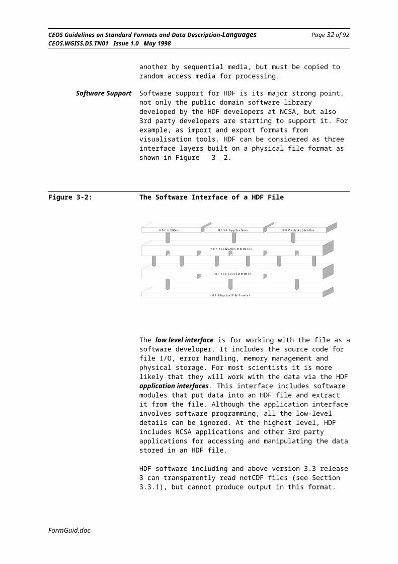
Software Support Software support for HDF is its major strong point, not only the public domain software library developed by the HDF developers at NCSA, but also 3rd party developers are starting to support it. For example, as import and export formats from visualisation tools. HDF can be considered as three interface layers built on a physical file format as shown in Figure 3-2.
2 Currently supported platforms include Convex (UNIX), Cray X-MP/2 (UNICOS), DECstation (Ultrix), HP 9000 (HPUX), IBM PC (MS-DOS/Windows), IBM RT (AIX), Macintosh (MacOS), IBM RS6000 (AIX), NeXT (NeXTStep), Silicon Graphics (Irix), Sun 3/Sun 386/Sparc (SunOS) and Vax (VMS, Ultrix)
FormGuid.doc

CEOS Guidelines on Standard Formats and Data Description Languages Page 23 of 92CEOS.WGISS.DS.TN01 Issue 1.0 May 1998
Figure 3-2: The Software Interface of a HDF File
H D F U t il i t ie s N C S A A p p lic a tio n s
H D F A p p lic a t io n In te r fa c e s
H D F L o w L e v e l In te r fa c e
H D F P h y s ic a l F ile F o rm a t
3 rd P a rty A p p lic a tio n
The low level interface is for working with the file as a software developer. It includes the source code for file I/O, error handling, memory management and physical storage. For most scientists it is more likely that they will work with the data via the HDF application interfaces. This interface includes software modules that put data into an HDF file and extract it from the file. Although the application interface involves software programming, all the low-level details can be ignored. At the highest level, HDF includes NCSA applications and other 3rd party applications for accessing and manipulating the data stored in an HDF file.
HDF software including and above version 3.3 release 3 can transparently read netCDF files (see Section 3.3.1), but cannot produce output in this format.
Long-term Stability HDF is not approved by any international standards body, and therefore users of the standard must be aware that future software libraries are not guaranteed to be backwards compatible (although NCSA keep this as the highest priority). A specification for HDF is available from NCSA, however, so a library could be re-developed at any future date. HDF is used extensively by the NASA EOSDIS project for Earth observation product delivery and therefore has powerful backing. However, its merits for long term archiving must be carefully considered, due to the embedding of the data description and the limited control that the international user community has over format development. This limited control could mean that in time there may be a proliferation of variations of the format as various organisations adapt it for their own use. However, the fact that a single group (NCSA) is responsible for the perpetuation of the format makes it less likely that proliferation will occur. There is simply no other group likely to create a prarllel implementaion of HDF.
Furthermore, as an HDF file is only practically accessible through the software library, the long-term accessibility of the data could be in question depending upon the continued software development and the changes in commonly used platforms.
Contact Point The developers and support staff for HDF can be contacted at:
FormGuid.doc
CEOS Guidelines on Standard Formats and Data Description Languages Page 24 of 92CEOS.WGISS.DS.TN01 Issue 1.0 May 1998
NCSA Software Tools Group, HDF152 Computing Application Building605 E. Springfield Ave.Champaign, IL 61820USA
Email: [email protected]
The HDF library and documentation is available via the WWW from:
http://hdf.ncsa.uiuc.edu/ftp://ftp.nsca.uiuc.edu/HDF
The documentation includes:
Getting Started with HDFNCSA HDF User’s GuideNCSA HDF Reference ManualNCSA HDF Specification and Developer’s Guide
Information on access to related software tools (including JAVA support) is also provided.
Additional Comments A development of HDF is HDF-EOS, which provides 3 new data models on top of existing HDF data models. The new models specifically address geo-referenced and geo-coded Earth observation data. HDF-EOS has its own User’s Guide.
Further information available via:
http://edhs1.gsfc.nasa.gov/
FormGuid.doc

CEOS Guidelines on Standard Formats and Data Description Languages Page 25 of 92CEOS.WGISS.DS.TN01 Issue 1.0 May 1998
3.3.3 CEOS Superstructure Format
General The Format Subgroup of the Committee on Earth Observation Satellites (CEOS) established the CEOS Superstructure Format[6] for Earth observation product delivery a number of years ago. It is widely used throughout the Earth observation community particularly for the distribution of SAR data. The format is based upon that developed for the Landsat mission. The aim of the CEOS Superstructure Format Usually referred to as simply the CEOS Format) is to minimise the effort needed to read and write data products from similar Earth observation sensors. This is achieved by establishing a standard for a family of formats, and then making further recommendations for specific sensor classes (for example, optical sensors and SAR sensors).
The CEOS Superstructure Format can be regarded as being semi-generic in that it consists of a generic component to define the superstructure of a file or set of files, combined with a partly generic fixed record format adjusted for particular types of data (e.g., SAR data or ERS Altimeter data). Unfortunately, due to the adoption of the format by a number of agencies (ESA, CCRS and NASDA in particular) and poor control by CEOS, the Format has developed a number of inconsistencies which has hindered the development of generic CEOS Format software.
The basic concept of the CEOS Superstructure Format is a series of files: A volume directory file globally describes the configuration of the
data set, including the physical and logical volume organisation, file pointer records and optional textual records. The first record of the volume directory file is the volume descriptor record, this is followed by one file pointer record for each data file within the logical volume, these are then optionally followed by any number of free format textual records for descriptive information;
Data files that contain the actual product data. The first record of the data file is the file descriptor record, which contains information on how to interpret the contents of the constituent records. In addition, each data file has a File Class which identifies a general categorisation of the data.It is usual to have three types of data files within a single product, these are the Leader File, the Imagery File and the Trailer File. The Leader File contains image introductory information, such as sensor specific reference for the scene, the product type, sensor and mission identification, etc. The CEOS has defined specific record formats for each of these information types. The Imagery File contains data records which contain imagery information and also support information which is synchronised to the pixel data, such as, quality codes, geolocation data, etc. The image pixels can be of a number of bit sizes and can be stored under a number of common schemes such as Band Interleaved by Pixel (BIP), Band Interleaved by Line (BIL) or Band Sequential (BSQ). The Trailer File is used to store quality control and other information that was not available at the start of processing, for example, a histogram of the preceeding image.
Finally there is a Null Volume Directory File at the end of the logical volume to indicate the end of the complete product.
A schematic of the CEOS Superstructure Format is shown in Figure 3-3.
FormGuid.doc

CEOS Guidelines on Standard Formats and Data Description Languages Page 26 of 92CEOS.WGISS.DS.TN01 Issue 1.0 May 1998
Figure 3-3: Schematic of the CEOS Superstructure Format
VolumeDirectoryFile
DataFile 1
DataFile 2
DataFile n
VolumeDirectoryFile
Volume Description Record
File Pointer Record 1
File Pointer Record 2
File Pointer Record n
Text Record(s) - optional
File Descriptor Record
Data Records
Volume Descriptor Record
File Descriptor Record
Data Records
File Descriptor Record
Data Records
(either null or next logical volume)
optional dependingupon a flag in the FDR
The 12 byte header at the start of each record contains a record sequence number, a record type and sub-type code (which identify the description of the record) and the record length. The type and sub-type codes are assigned by CEOS so that ‘standard’ records can be reused across similar products, for example, to indicate map projection data, ground control point data, SAR data, etc.
Additional information on the use of the CEOS Superstructure Format for the distribution of SAR data for specifc missions is given in Chapter 5.
Data Description Information The handling of data description information is very poor in CEOS files. When data is interchanged in CEOS files, there is a strong reliance on paper documentation to describe the parameters, particularly in the leader and header files. Whilst the format of a particular record type is given a unique CEOS type and sub-type identifier, the format ‘registered’ against this description does not have to conform to any particular format. The CEOS registration is also quite cumbersome as there is no infrastructure available to access such registered record formats.
Through the use of ‘Text Records’ it is possible to include annotation attributes for the product, but the format of these are user specific and there
FormGuid.doc

CEOS Guidelines on Standard Formats and Data Description Languages Page 27 of 92CEOS.WGISS.DS.TN01 Issue 1.0 May 1998
is no generally accepted standard. Languages such as Parameter Value Language (see Section 4.2.4), developed by the CCSDS, could be used for annotation attribute representation. The standard auxiliary information that is provided in leader records is provided in fixed field positions as defined by paper documentation. This technique is manageable when a large number of fixed products are distributed, but very inflexible.
Data Formatting or Packaging The CEOS Superstructure Format addresses only the general data packaging scheme. The syntax of the data that are within a single record can be defined by registered CEOS type and sub-type tags, and previously defined elements can be reused easily. The overall packaging is handled by the file blocks as described earlier. If more than one product is to be delivered simultaneously then another file can easily be written to the distribution media, followed by the end of volume file (a Null Volume Directory File).
Storage and Media Support The CEOS Superstructure was designed for products that are to be distributed on unlabelled tape, i.e. not random access media. It relies heavily on tape and end-of-file markers and all file references are relative to the start of a physical volume. A single product can span more than one physical volume and the various File Pointer Records can handle this simply. The limitation to sequential media is becoming significant in the modern day environment, where newer, more convenient, higher capacity random access media are desirable. There have been variations of the CEOS Superstructure Format designed to permit the files to be located on random access media and the File Pointer Records to contain filenames, rather than just numerical tape file numbers. Whilst this has worked successfully, there is no formal standard available on how this should be handled, it is purely organisation specific.
One area where the CEOS documentation (see ‘Contact Point’ below) is very poor, is the description of the data on the physical media. It is not clear what physical encoding is used, whether it is fixed by the standard or dependent upon the host machine that is writing the file.
Software Support There is no generic software available that reads or writes CEOS Superstructure Format files. Each of the agencies in the CEOS have developed their own software for generating or receiving products. Unfortunately due to the lack of a formally published specification of the CEOS Superstructure Format, the task of producing ‘generic’ software would be very difficult. There are also many cases of ‘CEOS compliant’ software from one agency not being able to read the products produced by another agency. Chapter 5 gives pointers to some of the software sources.
Long-term Stability As the CEOS Superstructure Format specification was produced by an international body that comprises most organisations and agencies that are interested in Earth observation, the potential for long term stability of the standard is good. However, the quality of the available documentation is poor and this compromises the potential for long term use of the standard.
Contact Point In the writing of this report it has been found that it is very difficult to find any positive contact source for CEOS information. There is no central point from which the format standard can be obtained. Documentation and
FormGuid.doc

CEOS Guidelines on Standard Formats and Data Description Languages Page 28 of 92CEOS.WGISS.DS.TN01 Issue 1.0 May 1998
software support is normally available from the specific data supplier. ESA/ ESRIN has a large section of its Guide and Directory Service (http://gds.esrin.esa.it/infosys) dedicated to CEOS material, however, there is no electronic version of the original CEOS specification document.
Contact points for SAR CEOS Format Products from various Space Agencies are given in Section 5.2. General queries can be addressed to the leader of the CEOS WGISS Format Guidelines Task Team, currently Wyn Cudlip on [email protected]
FormGuid.doc

CEOS Guidelines on Standard Formats and Data Description Languages Page 29 of 92CEOS.WGISS.DS.TN01 Issue 1.0 May 1998
3.3.4 MPH/SPH/DSR
General The MPH/SPH/DSR product format[7][8][9][10] is specifically used by ESA/ESRIN for ERS-1 and ERS-2 products and hence extensively throughout Europe. It is used for the Fast Delivery Products from the ground stations to the Processing and Archiving Facilities (PAFs) and to ESRIN, where it is archived in this format. This format also forms the current baseline for the Envisat-1 Ground Segment. The MPH/SPH/DSR format is generally not used for product distribution to end users, for this the CEOS SuperstructureFormat is used. Note, the format only specifies the structure of the data packaging, it is not concerned with the syntax or semantics of the individual data records.
Each product consists of three segments; the Main Product Header (MPH), the Specific Product Header (SPH) and the Data Set Records (DSRs) as shown in Figure 3-4.
Figure 3-4: Schematic of an MPH/SPH/DSR Formatted File
Optional
Main Product Header (MPH)
Specific Product Header (SPH)
Data Set Record (DSR)
::::::::
Data Set Record (DSR)
}
The MPH has a single fixed size record of 176 bytes that is mandatory for all products generated by any satellite. The MPH for any one satellite is always the same. This header indicates, in fixed fields, information which is applicable to all processing chain products, such as product identifier, type of product, spacecraft identifier, UTC time of beginning of product, ground station identifier, many quality control fields that are completed at various stages of the processing chain, etc. Following the MPH is the SPH, which is present only if indicated by the MPH. The SPH can have a variable number of records, each of variable size as dictated by the product type. These records contain information specific to a particular product. For example, product confidence data that is specific to a product type, parameters for instruments that are used to generate the product, etc. Finally there are a number of DSRs (as specified in the MPH also), that contain the actual scientific data measurements. The number and size of the DSR records is also dependent upon the product type.
There is only a limited number of data types that are supported in the headers, these are 1, 2 and 4-byte integers, ASCII string parameters, single byte flags and ‘special’ fields formatted for a particular product.
Data Description Information The MPH/SPH/DSR does not contain any data description information. The MPH and each of the SPH formats and fields are defined in conventional
FormGuid.doc

CEOS Guidelines on Standard Formats and Data Description Languages Page 30 of 92CEOS.WGISS.DS.TN01 Issue 1.0 May 1998
paper documents, there is no electronic formal language description of records. The MPH indicates the type of product, and from this the user would have to look up the relevant product specification and then know the type of SPH records and the type of DSR records. Using this method new SPH and DSR records can be defined and then a new identifier used in the MPH, but this is only a very basic method of data description.
Data Formatting or Packaging MPH/SPH/DSR is a method of packaging a product only, as the actual syntax of the data is not addressed. The high level structure, i.e. that shown in Figure 3-4, could be seen as the packaging level, but it has little flexibility, except in the number of SPH and DSR records. It is not possible to package more than one product within a single MPH/SPH/DSR structure, each product must be a single complete structure.
Storage and Media Support The low level format of the fields follow that of the DEC architecture in bit and byte representation, i.e. for integers. The products are distributed on one of three media types: computer compatible tape (CCT), Exabyte and optical disk. The standard assumes sequential media and there is a clear specification of how more than one product is stored on a single physical volume. There is no specification of how products could be stored on random access media. Whilst the logical product structure in Figure 3-4 is always followed, the physical structure on the media can follow different structures, depending upon product sizes and therefore where Inter-Record-Gaps (IRG) and End-of-File markers (EOF) are placed with respect to data set records (DSRs). Figure 3-5 shows two example for Exabyte tape storage.
Figure 3-5: Examples of MPH/SPH/DSR Media Format
S m a l l P r o d u c t F o r m a t L a r g e P r o d u c t F o r m a t
E O F
E O F
E O F
E O F
M P H , S P H , D S R s M P H , S P H , D S R sI R GD S R sI R G
I R GD S R s
Software Support There is no software support for MPH/SPH/DSR formatted files. Each user of the data must develop their own software. This has so far, always been done as part of a dedicated processing system and therefore no libraries or utilities are generally available.
Long-term Stability MPH/SPH/DSR formatted files are of great importance to ESA and therefore the format is likely to be used for a long period of time. All the ERS-1 and ERS-2 raw data is formatted in this way and ESA must make sure that the
FormGuid.doc

CEOS Guidelines on Standard Formats and Data Description Languages Page 31 of 92CEOS.WGISS.DS.TN01 Issue 1.0 May 1998
data will always be accessible. This is achieved by comprehensive paper documentation of each of the product formats, therefore in the future if current software is no longer available, then software development can start again from the physical file formats. There is no international body that supports MPH/SPH/DSR, therefore there is no control over any changes in the format as decided by ESA.
Contact Point It was very difficult to find a clear definition of the MPH/SPH/DSR format for this report. There seems to be no generic definition of the format, only the specific product definitions for the ERS-1 and ERS-2 missions. Whilst the definer of the format is ESA/ESRIN, it is not known which individual or department is responsible.
FormGuid.doc

CEOS Guidelines on Standard Formats and Data Description Languages Page 32 of 92CEOS.WGISS.DS.TN01 Issue 1.0 May 1998
3.3.5 Spatial Data Transfer Standard (SDTS)
General Spatial Data Transfer Standard (SDTS)[11] is a method for transferring spatial data, such as geographic and cartographic features, between heterogeneous computer systems. Specifications are provided for representing 13 different types of 0-, 1- and 2-dimensional real-world objects represented as vector or raster data. In addition to the ‘standard’ 13 simple spatial objects available, the user can define composite objects which are made up of simple objects.
An SDTS transfer consists of a grouping of modules, these modules can be broken down into four categories: Global Information Modules that define global parameters for the entire
transfer, such as the data set identifier, the co-ordinate system used, the geographic coverage, quality information, definition of attributes, etc.;
Attribute Modules that contain attributes of the spatial objects contained in the transfer, such as altitude, direction, etc., this is analogous to data description information;
Spatial Object Modules that define simple and composite structures of the basic spatial objects;
Graphic Representation that contain display symbols, area fill, colour, etc. for the various objects.
In SDTS, objects are defined by attributes. For example, a ROAD may have attributes LENGTH and DIRECTION. SDTS includes approximately 200 defined object names and 240 attributes.
For Earth observation, the vector representation is not of much interest, but the raster profile is applicable. The raster profile is a standard method of formatting raster data, such as images or gridded data, that must be geolocated. Raster modules can accommodate image data, digital terrain models, gridded GIS layers, and other regular point sample and grid cell data (all of which are termed raster data). Two module types are required for the encoding of raster data: the Raster Definition module and the Cell module. Additionally, a Registration module might be required to register the grid or image geometry to latitude/longitude or a map-projection-based co-ordinate system.
SDTS supports many different organisation schemes for encoding raster data. Other data recorded in the Raster Definition module complete the definition of the structure, orientation, and other parameters required for interpreting the raster data. Actual pixel or grid cell data values are encoded in Cell module records.
Data Description Information SDTS supports data dictionary modules that can be part of the transferred file. The data dictionary, consisting of three module types (Data Dictionary/Definition, Data Dictionary/Domain and Data Dictionary/Schema), convey the meaning and structure of entity and attribute data.
The Data Dictionary/Definition module defines the meaning of entity and attribute terms (called labels) and identifies a responsible body (called authority) for each definition.
The Data Dictionary/Domain module specifies the type and range of values each attribute may take and defines the meaning of attribute value codes.
The Data Dictionary/Schema module specifies the record layout of each attribute module in terms of which attributes are included, the type,
FormGuid.doc

CEOS Guidelines on Standard Formats and Data Description Languages Page 33 of 92CEOS.WGISS.DS.TN01 Issue 1.0 May 1998
format and maximum length of the attribute values, and which entity type (specified by label) is being characterised by the attributes.
Therefore the data description capabilities of SDTS are of a high quality and the data description information is managed in a relatively separate manner to the actual data it describes.
Data Formatting or Packaging SDTS defines a method for formatting the lower level atomic data using ISO 8211 (see next paragraph), and then uses the SDTS defined profiles for packaging the data. There is no simple method of taking a number of existing SDTS files and packaging them together, the data objects in each file would have to be extracted separately and a new file generated.
Storage and Media Support SDTS uses the ANSI/ISO 8211 ‘Specification for a Data Descriptive File for Information Interchange’[12] to encode the data being transferred. ISO 8211 is self describing. It contains the description of the data records and a description of the file itself. This level of description is at the lowest level, i.e. the bit and byte encoding and not the higher SDTS object level. Physical media for SDTS are any media that hold a string of bytes, therefore files can be conveyed on either sequential or random access media. Although due to the fact that ISO 8211 is used to encode the physical elements, the physical media must be formatted conforming to ANSI/ISO standards.
Software Support Public Domain software is being developed to support SDTS (see the ftp site given at the end of this Section). There is also software to support ISO 8211 encoding/decoding (FIPS 123 Functional Library). It is written in ANSI C and available on IBM-PCs and Data General AViiON Unix workstations.
Long-term Stability SDTS is a U.S. government FIPS standard and therefore is guaranteed to be supported into the foreseeable future. It is the responsibility of the USGS (United States Geological Survey) to maintain and develop it. Whilst it is not an internationally approved standard, the FIPS approval makes it a mandatory option for spatial data exchange within U.S. government organisations.
Contact Point The developers and support for SDTS can be contacted at:
Email: [email protected]
There is also a WWW page and FTP site for further SDTS information and example files at:http://mcmcweb.er.usgs.gov/sdtsftp://sdts.er.usgs.gov/pub/sdts
FormGuid.doc
CEOS Guidelines on Standard Formats and Data Description Languages Page 34 of 92CEOS.WGISS.DS.TN01 Issue 1.0 May 1998
3.3.6 Flexible Image Transport System (FITS)
General FITS (Flexible Image Transport System)[13][14] is a data format designed to provide a means for convenient exchange of astronomical data between installations whose standard internal formats and hardware differ. The format is unlikely to be used significantly for EO data. Its brief description is included here as an example of another widely used formatting system.
A FITS file is composed of a sequence of Header Data Units (HDUs). The header consists of keyword=value statements, which describe the format and organisation of the data in the HDU and may also provide additional information, for example, about instrument status or the history of the data. The data follows, structured as the header specifies. The data section of the HDU may contain a digital image, but it is not required to. Other data types supported include tables and multidimensional matrices.
The first HDU must contain a multidimensional matrix or no data at all; the data in subsequent HDUs, called extensions, may be of any type, consistent with certain rules. The “Image” in the name comes from the original use of the format to transport digital images, but it is not just for images any more. FITS supports 5 data types in the multidimensional array of the first HDU: 8-bit unsigned binary integers, 16-bit twos-complement signed binary integers, 32-bit twos-complement signed binary integers, 32-bit IEEE-754 standard floating point numbers, and 64-bit IEEE-754 floating point numbers.
Two new extension types, binary tables (type name BINTABLE) and images (type name IMAGE), are currently under consideration for endorsement by the IAU FITS Working Group. FITS is not very suitable for formatting arbitrary scientific data values. The only method of doing this is to use the binary table extension, where a single row of the table is defined with various fields, but then the table is limited to one row. Also the data types for scientific data is limited to the basic data types as listed above and therefore non-standard bit sized numbers cannot be handled.
An example FITS file is shown in Figure 3-6 below, this clearly shows the simple layout and capabilities.
FormGuid.doc

CEOS Guidelines on Standard Formats and Data Description Languages Page 35 of 92CEOS.WGISS.DS.TN01 Issue 1.0 May 1998
Figure 3-6: Sample FITS Image File.........1.........2.........3.........4........5..........6.........7.12345678901234567890123456789012345678901234567890123456789012345678901SIMPLE = T / FITS TAPE WRITTEN AT KPNO, 04/18/80.BITPIX = 32 / 4-BYTE, 2-S COMPLIMENT INTEGERS.NAXIS = 2 / NUMBER OF AXIS.NAXIS1 = 256 / NUMBER OF PIXELS PER ROW.NAXIS2 = 180 / NUMBER OF ROWS.BSCALE = 1.00000E-06 / PHYSICAL=INTEGER*BSCALE+BZERO.BZERO = 0. /BLANK = -2147483648 / INTEGER VALUE FOR BLANK PIXEL.IPPS-RF = ‘D /013’ / RASTER LFN/RASTER ORDINAL.IPPS-ID = ‘N4486 NUCLEUS AND JET 4350 [9 BAD PIXELS BLANKED] ‘/IPPS-B/P= 30 / BITS/PIXEL OF IPPS RASTER.IPPS-MIN= 3.700018E-02 / MINIMUM VALUE IN RASTER.IPPS-MAX= 1.19825 / MAXIMUM VALUE IN RASTER.ORIGIN = ‘KPNO -- WIFTS OF 04/17/80.’ /DATE = ‘18/04/80’TIME = ‘10.11.54’COMMENT THIS FILE TESTS THE 32-BIT PIXEL FORMATCOMMENT IT ALSO TESTS THE BLANK PIXEL CONVNETION. THERE ARE 9 BLANKSCOMMENT IN THIS IMAGE. THEY ARE A DETECTOR BLEMISH AREA.
OBJECT = ‘NGC4486 =M87 AND JET’ /TELESCOP= ‘MAYALL4M’ / MAYLL 4-METER SCOPE AT KITT PARKINSTRUME= ‘VIDEOCAM - MAYALL 4M CASSEGRAIN ‘ /
END
(256x180x4 bytes follow)
Data Description Information FITS is self describing to the extent that it includes in the HDUs attributes that describe the data that follows. For example, the pixel data type, the number of axes, the scale, etc. Also the user can include any non-standard attributes that are required to add more descriptive information. This makes a FITS file easily understandable to a human user. What is not defined in the interchange is the meaning of the various parameters. Therefore, the software that is to read the image must know the various parameter definitions and how to use them. This situation is not a problem for established standard parameters, but it will not be possible to process any user defined parameters automatically.
Data Formatting or Packaging FITS is a relatively simple format for a well defined function, that of formatting multidimensional arrays. The format limits the possible representation of the array elements (pixels in the case of images). There may be a number of arrays following the HDU, but this is the only concept of packaging. It is not possible to randomly add data objects of different types to the FITS file.
Storage and Media Support Each logical record in a FITS file is always 2880 bytes, the sub-records within the HDU consist of 36 ‘card images’, each of 80-bytes, written in 7-bit ASCII. The END card image is always the last, the remainder of the header is padded with blanks to the full 2880 byte length. The card records are followed directly by the data. The data is physically formatted according to IEEE standards. As shown in Figure 3-6 the layout of the card images is in firmly fixed character positions.
FITS is defined as a logical structure and independent of media. Therefore the files can be transferred on sequential media, such as magnetic tape, or
FormGuid.doc

CEOS Guidelines on Standard Formats and Data Description Languages Page 36 of 92CEOS.WGISS.DS.TN01 Issue 1.0 May 1998
random access media. As FITS does not permit the reference of data outside of the one physical file, it means the complete product must be contained within a single physical file. There have been non-standard conventions for spanning products across more than one physical media volume, but these are not universally supported.
Software Support FITS is supported by a number of software packages, the main source of which is NASA/GSFC, the primary supporter of FITS. GSFC has developed a package of FORTRAN subroutines, called FITSIO. This package provides software for easy reading and writing of FITS format files. FITSIO runs on most common machines. It supports all the currently defined standard FITS extensions; it also supports the proposed IMAGE and BINTABLE extension types. There are a number of FITS viewers available also for various platforms.
Long-term Stability FITS is an approved standard by the International Astronomical Union (IAU). The most comprehensive support for FITS is provided by the NASA Office of Standard and Technology (NOST) also at GSFC. FITS is seen as a very stable format with a large if somewhat specialised user community.
Contact Point The NOST Librarian provides electronic and printed copies of many of the FITS documents. They can be contacted at:
NASA/Science Office of Standards and TechnologyCode 633.2Goddard Space Flight CenterGreenbelt MD 20771USA
Email: [email protected]
Good FTP sites for documentation and software are:
ftp://legacy.gsfc.nasa.govftp://nssdc.gsfc.nasa.gov/pub/fits
FormGuid.doc

CEOS Guidelines on Standard Formats and Data Description Languages Page 37 of 92CEOS.WGISS.DS.TN01 Issue 1.0 May 1998
3.3.7 Graphics Interchange Format (GIF)
General The Graphics Interchange Format (GIF)[15] defines a protocol intended for the network transmission and interchange of raster graphic data in a way that is independent of the hardware used in their creation or display. GIF is defined in terms of blocks and sub-blocks which contain relevant parameters and data used in the reproduction of an image. In general, the images in a GIF data stream are assumed to be related to some degree, and to share some control information.
A schematic of the GIF file format is shown in Figure 3-7.
Figure 3-7: Schematic of a GIF File
Use Word 6.0c or later to
view Macintosh picture.
The GIF format is a fixed format that may be suitable for distributing some browse products. There is global palette for each file and the possibility to associated a local palette with an individual image. The image can be of any dimension, but are limited to 1, 2, 4 or 8-bit pixels. The values in the pixels are then looked up against an RGB palette for display purposes. A particular advantage of GIF for browse product distribution is the lossy data compression that is included and the easy availability of display tools for practically every known platform.It is difficult to store other data in a GIF file except for images and palettes. There is a place for text in GIFs, but most display applications ignore it.
Data Description Information There is no data description information in a GIF file, except for the basic image dimensions and pixel depth. (See comment above.)
Data Formatting or Packaging It is possible to package more than one image in a single GIF file, but it is up to the display software to interpret the relationship between the images, that
FormGuid.doc

CEOS Guidelines on Standard Formats and Data Description Languages Page 38 of 92CEOS.WGISS.DS.TN01 Issue 1.0 May 1998
is, there is no way to indicate if the images are of different bands of the same area or related in any other way. The format of the pixels is strictly defined by the standard.
Storage and Media Support The pixel data is stored as a bit stream as it is compressed using a variation of the LZW compression algorithm[16]. GIF files can be distributed on sequential or random access media. There is no way to split a GIF file apart, the image must always be contained in a single file, so the media type is immaterial.
Software Support There are many software packages that import and export GIF files. The source code for many GIF encoders and decoders is freely available from many FTP sites.
Long-term Stability GIF is defined by the CompuServe Inc. company in the USA. Whilst it is not an international standard, there are many tera-bytes of images available and interchanged in GIF format. This means that the format is a well established defacto standard and is unlikely to change. There have been extensions to the basic standard, but none of these invalidate the basic format described here.
Contact Point There is no real purpose in providing a contact point for the GIF format designers, as it is a private company who do not accept feedback or provide support. For software that is available to generate and read the GIF format, many anonymous FTP sites on the Internet are available.
Additional Comments There is also a copyright issue with some uses of GIF. The LZW compression algorithm is owned by a commercial concern and a charge may be assessed for certain types of use.
A replacement for GIF called PNG (Portable Network Graphics) has been proposed (see ftp://ftp.uu.net/graphics/png/README and http://www.eps.mcgill.ca/~steve/PNG/png.html).
FormGuid.doc

CEOS Guidelines on Standard Formats and Data Description Languages Page 39 of 92CEOS.WGISS.DS.TN01 Issue 1.0 May 1998
3.3.8 ISO/IEC 12087 - Image Processing and Interchange
General ISO 12087 or ‘Information Technology - Computer Graphics and Image processing - Image Processing and Interchange’ standard is an ISO standard for the representation and manipulation of images in a digital form.
The ISO 12087 standard is in three parts; the Common Architecture for Imaging[17] which describes the common architectural material on which the entire standard is based; the Programmers Imaging Kernel System (IPI-PIKS) Application Program Interface (API) which defines the processing operations to be carried out on an image; and the Image Interchange Facility (IPI-IIF)[18], which defines how images may be interchanged between application programs. For the purpose of this study the IIF is the more important, although the eventual availability of software tool kits to support the API will encourage the use of the standard. Figure 3-8 shows the relationship between the parts of the IPI implementation.
Figure 3-8: Interfaces Between the Parts of the ISO 12087 Standard
Application Program
ParseGenerate
ParseGenerate
PIKSData Objects IIF
IPI dataPIKS data
PIKS
PIKS domain IIF domain
data
data flow according to ASN.1 specification within IIFimplementation-dependent internal data flow
Applicationdomain
The IIF data format (IIF-DF) is the format used for image interchange. The overall format follows the basic structure shown in Figure 3-9.
Essentially the structure holds information identifying the data and then within the contents body the actual data of interest. This can be images, image related data, attributes, annotations or basic data objects. The image structure itself can be broken down into much more detail as shown in ISO 12087 standard. This would then show the image records, the bands, the pixels etc.
FormGuid.doc

CEOS Guidelines on Standard Formats and Data Description Languages Page 40 of 92CEOS.WGISS.DS.TN01 Issue 1.0 May 1998
Figure 3-9: Overall Structure of the IIF-DF File
F u l l D a t a F o r m a t
F o r m a t D e s c r i p t o r C o n t e n t s H e a d e r C o n t e n t s
C o n t e n t s B o d y
I m a g e
I m a g e S t r u c t u r e R e f e r e n c e d U n i t
I m a g e R e l a t e d D a t a A t t r i b u t e s
. . . .
. . . .
f o r m a t i d e n t i f i c a t i o n ,v e r s i o n , p r o f i l e
t i t l e , o w n e r ,t i m e , e t c . ,
f i e l d s o f p i x e l s ; r e p r e s e n t e dw i th i n o n e o r m o r e d a t a u n i t s
d e s c r i p t i o n o f t h ei m a g e s t r u c t u r e
f u r t h e r i m a g e so r o t h e ra t t r i b u t e s
ISO 12087 defines a large number of data types that can be aggregated together to form a product. These data types include: Basic data types: integer, real, bit, boolean, character, enumerated, state
and null; Compound types: list, array, character string, choice, range, record, set,
pointer and table; Image types: elementary image (in which each pixel is of a basic type)
and compound image (in which each pixel is of a compound type); Non-image data related to imagery, such as histogram, palettes, look-up
tables, region of interest, text, etc. Metadata such as image attributes can also be included in the format, as
well as user defined attributes.
This flexibility and high degree of modularity is supported due to the fact that the format is defined and encoded using ISO 8824, ‘Abstract Syntax Description Notation.One’ (ASN.1)[19]. This provides a separate layer for the physical encoding, therefore the format designers only have to consider the abstract level.
Data Description Information As the IIF-DF is defined using ASN.1, it means that there is a complete data description of the format. The data description (which is in the ISO 12087 part 3 standard) is of the full generic data format. This, of course, covers every possible instance of the format, the difference in each instance being dependent upon the various selections and choices in the generic description. The IIF-DF also supports many predefined annotation attributes and user defined annotation attributes, these can be given meaningful names and accessed by name via the well defined API. Each data object within a single IIF-DF file can have annotation attributes attached to it.
Data Formatting or Packaging Using ASN.1 for encoding means that IIF-DF defines the format of each data element via the ASN.1 Basic Encoding Rules (as defined in ISO 8825 [20]). This means that the user need not be concerned with the actual data format
FormGuid.doc
CEOS Guidelines on Standard Formats and Data Description Languages Page 41 of 92CEOS.WGISS.DS.TN01 Issue 1.0 May 1998
although it could be deduced. Due to the recursive capability of ASN.1, any number of images and objects can be put into a single file, therefore the ‘packaging’ capabilities of the format are infinite as long as the basic structure as shown in Figure 3-9 is followed. For example, there is one format descriptor and contents header for each file. To package the contents of a number of separate files into one file would require each file to be unpackaged, and a new single file generated by packaging all the data objects back together again.
Storage and Media Support As already stated the IIF-DF data is formatted at the lowest level according to the ASN.1 basic encoding rules. The ISO 12087 standard defines each of the ASN.1 segments that are required for each data type supported. Users then aggregate these according to their needs. Physically, the data is encoded using the ISO 12089[21] standard, which is an extension to the normal ASN.1 basic encoding rules, in that it defines the encoding of some of the IIF types not defined by the ASN.1 basic rules. The format relies upon tags within the data to identify the next segment of information. This canonical encoding makes the format interchangeable between any systems that have the necessary ASN.1 encoder/decoder software. In line with ASN.1 philosophy, the file must be a single file and is treated as a stream of bytes, therefore it is not possible to span a single IIF-DF across more than one physical volume.
Software Support Even though the ISO 12087 standard is relatively new, there is a concerted effort underway by the developers of the standard to develop the necessary support software. The major development is called the ‘IIF Toolkit’ [22] developed by the Fraunhofer Institute for Computer Graphics in Darmstadt, Germany. It basically supports the API as defined in the ISO 12087 part 2 standard. The library can be used to read and write IIF-DF formatted data and then various APIs are provided to manipulate the resulting images. The IIF Toolkit relies upon the availability of the ISO development environment for the encoding and decoding of ASN.1.
Both the IIF Toolkit and the ASN.1 Development Environment are freely available by FTP and available for various flavours of Unix systems.
Long-term Stability Being an ISO standard the format is seen as very stable far into the future. The software still needs further development and does not yet support the full ISO 12087 defined API. Whilst the stability of the actual standard is very good, the format relies heavily upon complex software for encoding and decoding. As with any reliance upon software for data access there is a certain amount of risk that it may no longer be possible to compile the software in 20 years time. It is possible, due to the fact that all the encoding used is clearly defined by various ISO standards, to understand the data down to the bit level without software, but this would be a very complex task, and probably easier to rewrite the required software libraries.
FormGuid.doc

CEOS Guidelines on Standard Formats and Data Description Languages Page 42 of 92CEOS.WGISS.DS.TN01 Issue 1.0 May 1998
Contact Point There is no direct contact to the ISO committee responsible for the development of the standard, but the IIF Toolkit developers can be contacted (their team includes the primary editor of the ISO standard):
Christof BlumFraunhofer Institute for Computer Graphics, Wilhelminenstr 764283 DarmstadtGermanyInternet e-mail: [email protected] site for the IIF Toolkit: ftp://ftp.igd.fhg.de
FormGuid.doc

CEOS Guidelines on Standard Formats and Data Description Languages Page 43 of 92CEOS.WGISS.DS.TN01 Issue 1.0 May 1998
3.3.9 Standard Formatted Data Units (SFDU)
General Standard Formatted Data Units (SFDUs)[23][24] have been developed by the Consultative Committee for Space Data Systems (CCSDS). The SFDU concept is not a method of formatting data, but a method of structuring, packaging and organising the data, along with associated metadata and data description information. This means the SFDU is very strong in data management and particularly suited for delivery and long term archiving.
The SFDU format is used to package together data of any format. This is achieved by adding a small header (the LABEL field) to each block of data (the VALUE field) that is to be packaged, irrespective of the data’s format. This object, called a Label-Value-Object (LVO), is shown in Figure 3-10.
Figure 3-10: An SFDU Label-Value-Object (LVO)
Various field specificationare possible
Field of variable size, containing any format
of data
Existence based on Label field values
LABEL
VALUE
OPTIONALMARKER
The Label field includes the following: An identifier of the description of the data that follows the Label.
This identifier indicates the organisation that is responsible for the maintenance and availability of the data description as well as the unique identifier within the organisation.
A high level indication of the type of data that follows the Label. For example, this may be data description information, application data, data that is used as part of the SFDU standard for packaging purposes, etc.
An indicator of how the data following the Label is delimited. For example, the exact number of bytes may be specified, a number of end-of-file markers, a unique marker pattern within the data stream, etc.
To achieve the packaging and nesting of data objects it is possible to put a number of LVOs as the Value field of a ‘higher level’ LVO. This technique of nesting can continue indefinitely and therefore it is easy to manage and merge existing data products. An example of a more complex SFDU structure is shown in Figure 3-11.
FormGuid.doc

CEOS Guidelines on Standard Formats and Data Description Languages Page 44 of 92CEOS.WGISS.DS.TN01 Issue 1.0 May 1998
The shortage of software support One of the main drawbacks to SFDUs is the paucity of sophisticated software tools. The lack of an encoding standard invites the proliferation of “standards” that could make the task of interpreting historical data very difficult.
Figure 3-11: An SFDU Packaged Data Product
Data product productioninformation
Packaging LVO Label
Data set
Production Information LVO Label
Catalogue Information LVO Label
Application Data LVO Label
Catalogue informationfor the data set
LV
L
LL
V
V
V
Data set
Application Data LVO LabelL
V
The figures above show the SFDUs logically. In practice, the standard supports the storage of the data, i.e. the LVO value fields, either physically in the same file or stored as separate physical files and referenced from a ‘parent’ SFDU.
Data Description Information All data that is packaged using the SFDU standard must have a separate data description, whether it be in a natural language or a formal data description language. One of the major advantages of the SFDU concept over many other data formatting/packaging methods is that the data description must be registered with what is called the Control Authority Organisation [25][26]. This organisation, which consists of each of the member agencies of the CCSDS, is obliged to archive and make available all data descriptions it registers. If for some reason a Control Authority at a single agency ceases to exist, then the other agencies are obliged to accept responsibility for the data descriptions. This means data descriptions are guaranteed to be available for as long as any of the member agencies of the CCSDS exist. Unfortunately, the quality of the descriptions cannot be guaranteed!
All data have an identifier that indicates to the user where the data description is registered. The user can however request the data description from any agencies Control Authority and the Control Authority will forward the request as necessary. This means that the user need have only a single point of contact. The data description can also be packaged with the data that it describes; this results in a fully self-describing product for delivery. The SFDU standard itself does not specify the data description languages which may be used, but provides the infrastructure to support any language and
FormGuid.doc
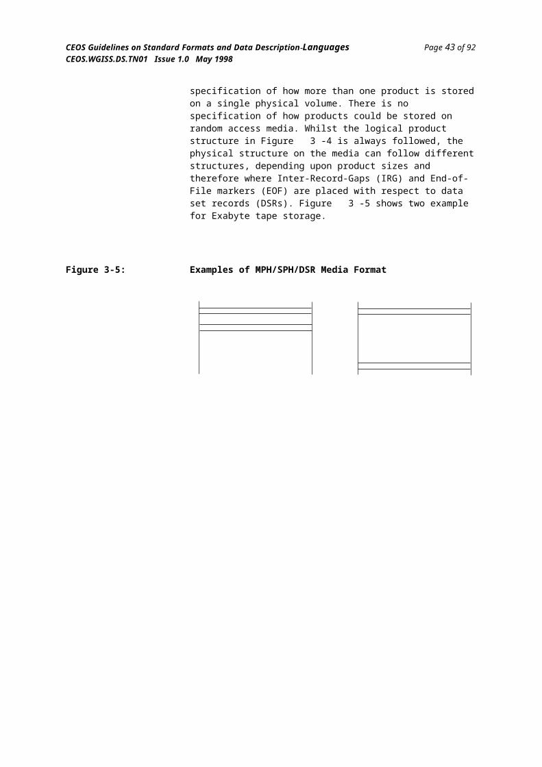
CEOS Guidelines on Standard Formats and Data Description Languages Page 45 of 92CEOS.WGISS.DS.TN01 Issue 1.0 May 1998
associate the description with the relevant data. There are other CCSDS standards that define formal data description languages (see next Chapter).
Data Formatting or Packaging The SFDU concept is clearly designed to perform the task of data packaging and does not at all cover the area of data formatting. This is one of the strengths of the standard; it clearly splits the atomic data formatting apart from the overall packaging. The packaging technique is extremely flexible and yet simple; there is no restriction on the data blocks that can be packaged together, and special LVOs defined by the standard permit the inclusion of other LVOs or data blocks physically separate from the main file. There is no restriction on the format of the data within the data blocks (LVO Value fields) so long as it is possible to provide a data description in either a formal description language or natural language.
Storage and Media Support SFDUs are treated as a stream of bytes. It is specified that the Labels are represented in ASCII, but this is the only restriction. It is possible for a single SFDU product to comprise of a number of separate physical files. From the logical view they are all perceived as a single logical SFDU. This is because the ‘top level’ SFDU points to each separate file. Note, though, a subordinate SFDU file cannot be recognized as being a part of a larger entity and so care must be excercised in file management. There is the limitation, at present, that it is not possible to have a single logical SFDU span more than one physical volume. This is due to the fact that the pointers from the ‘top level’ SFDU are relative to the volume that the top level SFDU is stored upon. Due to the method that is used to reference external data files, it is feasible that this limitation may be removed in a later version of the SFDU standard, the CCSDS are currently reviewing this situation.
SFDUs can be transferred and assessed directly from sequential media, random access media or directly from a communication channel. There are certain delimitation techniques for the LVOs that are not supported on one type of media and are on another. For example, delimiting an LVO with a number of end-of-file markers is not possible on random access media, but copying an SFDU product from one media type to another is relatively simple as the data does not require manipulation, only changes to the delimitation techniques used. (However, without accepted and standarized methods for translating between different delimiting techniques, there is no way to be sure that the proper technique has been followed during a transfer between different media types.)
Software Support Software support for the SFDU standard is in a relatively early stage of development, although there are a number of developments on-going. NASA/GSFC and ESA/ESOC are developing, in collaboration, the ‘SFDU Workbench’. This is a Unix/Motif based tool that can be used to create SFDUs and parse and unpackage SFDUs. It has the capability to associate external software packages with a particular data description identifier in the Label of an LVO. After schematically displaying the structure of the SFDU, the user can click on a Value field and the relevant package to process/display/ manipulate the data is executed. This workbench is still under development, but promises to be a very intuitive framework for manipulating data from any discipline packaged in SFDU format.
There is also an SFDU toolkit, developed by NASA/JPL that provides a software library interface written in ‘C’ for packaging data into SFDUs, and also for extracting the Value fields from SFDUs for an application program. This package is well documented and supported by NASA/JPL.
FormGuid.doc
CEOS Guidelines on Standard Formats and Data Description Languages Page 46 of 92CEOS.WGISS.DS.TN01 Issue 1.0 May 1998
Long-term Stability As the CCSDS is a recognised international standards body, the stability of the standard is very high. Recently the standard has also been endorsed and published as an ISO standard (ISO 12175)[27]. The standard is not software dependent, and the CCSDS put a high priority on data being accessible in 10 or 20 years time, as this is often the longevity of space related data. Essential to the SFDU concept is the availability of data descriptions for any data packaged in SFDUs. There is an agreement between the CCSDS member agencies that if any agency should stop performing the functions of the Control Authority (data description registration, archive and dissemination), then one of the other agencies shall assume the role for the relevant data descriptions. This means that the long term stability and accessibility of SFDU data itself is very high.
Contact Point The official contact point for obtaining CCSDS standards is:
CCSDS SecretariatAttn.: John Rush Program Integration Division, Code OI National Aeronautics and Space Administration Washington, DC 20546 USA
Email: [email protected]
WWW site:http://www.gsfc.nasa.gov/ccsds/ccsds_home.html
WWW site for the SFDU Toolkit (minimal support) and the SFDU Workbench (under development):
http://www.ccsds.org/ccsds/p2/software.html
FormGuid.doc

CEOS Guidelines on Standard Formats and Data Description Languages Page 47 of 92CEOS.WGISS.DS.TN01 Issue 1.0 May 1998
3.3.10 GeoTIFFThe following general description is extracted from theIntroduction in the current GeoTIFF Specification Document.
General Aldus-Adobe's public domain Tagged-Image File Format (TIFF has emerged as one of the world's most popular raster file formats. But TIFF remains limited in cartographic applications, since no publicly available, stable structure for conveying geographic information presently exists in the public domain.
Several private solutions exist for recording cartographic information in TIFF tags. Intergraph has a mature and sophisticated geotie tag implementation, but this remains within the private TIFF tagset registered exclusively to Intergraph. Other companies (such as ESRI, and Island Graphics) have geographic solutions which are also proprietary or limited by specific application to their software's architecture.
The GeoTIFF spec defines a set of TIFF tags provided to describe all "Cartographic" information associated with TIFF imagery that originates from satellite imaging systems, scanned aerial photography, scanned maps, digital elevation models, or as a result of geographic analyses. Its aim is to allow means for tying a raster image to a known model space or map projection, and for describing those projections.
GeoTIFF does not intend to become a replacement for existing geographic data interchange standards, such as the USGS SDTS standard or the FGDC metadata standard. Rather, it aims to augment an existing popular raster-data format to support georeferencing and geocoding information.
The tags are to be considered completely orthogonal to the raster-data descriptions of the TIFF spec, and impose no restrictions on how the standard TIFF tags are to be interpreted, which color spaces or compression types are to be used, etc.
GeoTIFF fully complies with the TIFF 6.0 specifications, and its extensions do not in any way go against the TIFF recommendations, nor do they limit the scope of raster data supported by TIFF.
GeoTIFF uses a small set of reserved TIFF tags to store a broad range of georeferencing information, catering to geographic as well as projected coordinate systems needs. Projections include UTM, US State Plane and National Grids, as well as the underlying projection types such as Transverse Mercator, Lambert Conformal Conic, etc. No information is stored in private structures, IFD's or other mechanisms which would hide information from naive TIFF reading software.
GeoTIFF uses a "MetaTag" (GeoKey) approach to encode dozens of information elements into just 6 tags, taking advantage of TIFF platform-independent data format representation to avoid cross-platform interchange difficulties. These keys are designed in a manner parallel to standard TIFF tags, and closely follow the TIFF discipline in their structure and layout. New keys may be defined as needs arise, within the current framework, and without requiring the allocation of new tags from Aldus/Adobe.
GeoTIFF uses numerical codes to describe projection types, coordinate systems, datums, ellipsoids, etc. The projection, datums and ellipsoid codes are derived from the EPSG list compiled by the Petrotechnical Open
FormGuid.doc
CEOS Guidelines on Standard Formats and Data Description Languages Page 48 of 92CEOS.WGISS.DS.TN01 Issue 1.0 May 1998
Software Corporation (POSC), and mechanisms for adding further international projections, datums and ellipsoids has been established. The GeoTIFF information content is designed to be compatible with the data decomposition approach used by the National Spatial Data Infrastructure (NSDI) of the U.S. Federal Geographic Data Committee (FGDC).
While GeoTIFF provides a robust framework for specifying a broad class of existing Projected coordinate systems, it is also fully extensible, permitting internal, private or proprietary information storage. However, since this standard arose from the need to avoid multiple proprietary encoding systems, use of private implementations is to be discouraged.
Data Description Information In principle, the standard TIFF tags could be used to store additional data description information, although the information might be difficult to access with standard software.
Data Formatting or Packaging GeoTIFF only deals with standard raster images. Apart from encapsulating the geo-reference information there are no packaging aspects to the format.
Storage and Media Support GeoTIFF is not affected by the form of the media.
Software support The availability of software to support the format is increasing rapidly and many GIS packages can now read the format.
Libgeotiff is a full-function library that reads and writes the GeoTIFF data, and is located at ftp://mtritter.jpl.nasa.gov/pub/tiff/geotiff/
There is also a mailing list for discussion [email protected]; to subscribe send email to [email protected] with subscribe geotiff your-name-here in the body of the email.
Long-term stability Although a format which essentially depends on continuing software support, the long term prospects for the format are good. The underlying structure is relatively simple, and although continuing development with the additional of new tags is likely, there is a good chance that backward compatibility will be maintained.
Contact Point The GeoTIFF web page contains links to additional information:
http://www-mipl.jpl.nasa.gov/cartlab/geotiff/geotiff.html
Samples are available at the USGS GeoTIFF site:
ftp://ftpmcmc.cr.usgs.gov/release/geotiff/samples
FormGuid.doc
CEOS Guidelines on Standard Formats and Data Description Languages Page 49 of 92CEOS.WGISS.DS.TN01 Issue 1.0 May 1998
3.4 Formats Summary ComparisonThis section provides a summary of the suitability of the various ‘standard’ generic formats against a number of criteria that are important to the engineer requiring to select a format for a particular task. Many of the formats have similar capabilities, but the techniques used to implement the capabilities can have a major effect on how easy the format would be to use in practice. Therefore, in Table 3-1 some of the capabilities are indicated as a Yes or No, whilst others get from zero to 3 tick marks to indicate suitability to task; the former indicating the capability is not supported at all, the latter indicating full support by design.
So that the reader can assess the suitability of formats for a particular task, Table 3-2 below illustrates where the formats have been used in existing domains and systems. This is not intended to be an exhaustive list and can be expanded as further examples become available and knowledge is gained.
FormGuid.doc
CEOS Guidelines on Standard Formats and Data Description Languages Page 50 of 92CEOS.WGISS.DS.TN01 Issue 1.0 May 1998
Table 3-1: Standard Formats Comparison
Capability CDF/netCDF
HDF CEOS MPH/SPH/DSR
SDTS FITS GIF ISO/IEC 12087
SFDU geoTIFF
Format version analysed 2.5 4.0 ?3 ? ? ? 87a ? 3 ?
Product formatting
Predefined image types
-
Arbitrary data types n - n
n-bit data types n n n n
y4 n
Annotation data
n -
Self identifying data types n n n - n
Interpreted data description n n n n n n n n y5 n
Product packaging
Addition of products
n n n
n
Separate storage of annotation attributes
n n y y y y n n y n
Separate formatting from packaging
n n y y n n n n y n
Multiple files y n y y n n n n y n
Multiple physical media n n y y n n n n n n
Media
Media independence n n n n y y y y y y
Random access media y y n n y y y y y y
Sequential access media n n y y y y y y y y
Software support
n n n
Data access without software n n
n n
n
Processing efficiency
?
?
Storage efficiency
?
?
Current widespread use6
Doc. availability/readability
Long-term stability
- indicate the capability has no relevance to the format
3 The ‘?’s in this row indicates that the format does not indicate any version information, either within the data or within the format documentation.
4 By virtue of the SFDU concept, any data packaged may be defined in any way.5 By virtue of the SFDU concept, all data packaged must have an data description.6 Those formats that indicate high widespread use, indicate large data volumes
available in specialised areas only, i.e., HDF in EOSDIS, CEOS for SAR, MPH/SPH/DSR for ERS-1/2 missions, FITS for astronomy
FormGuid.doc
CEOS Guidelines on Standard Formats and Data Description Languages Page 51 of 92CEOS.WGISS.DS.TN01 Issue 1.0 May 1998
Table 3-2: Illustrative Systems using Standard Formats
Format Example Systems and Domains
CDF/netCDF CDF is used extensively in NASA for archiving astrophysics data such as the ISTP missions and also for the Halley’s Comet Encounter mission data.
HDF HDF is the baseline formatting standard for the NASA EOSDIS project. This is NASA’s system for the archiving and distribution of Earth observation products into the next century. HDF is also used by a number of academic establishments for modelling and visualisation of dynamic data, such as climatic systems.
CEOS The CEOS Superstructure is used within the current Earth observation community as a distribution format to end users. It is mainly used for SAR products, altimeter products, etc. from a number of missions such as LANDSAT, NOAA, ERS-1/2.
MPH/SPH/DSR This format is only used within the internal ESA ground segment for the ERS-1/2 missions. It is directly generated by the ground stations and the products passed to the primary data centres in this format. Whilst the volume of data in this format is large, the domain is specialised.
SDTS Even though SDTS is an approved U.S. government standard, there is currently no major examples known of its use. There has been sample data taken from earthquake databases of the USGS and reformatted in SDTS, but not for general distribution.
FITS FITS is the defacto standard for all astronomy image data produced; whether it be visible, IR or X-ray images. Missions such as EXOSAT, XMM and Hubble all produce their user products in FITS format.
GIF GIF is widely used in many domains, from browse images for Earth observation data to image formats for PC applications. The ESRIN Multi-Mission Browse Service (MMBS[42]) uses GIF as the dissemination format for interface to the user.
ISO/IEC 12087 ISO 12087 is a relatively new standard and there is currently little widespread use. This is partly due to the fact that the software libraries required to generate the format are still in their early stages. It is anticipated that once the support tools are generally available, the format will become more important due to its ISO status.
SFDU The SFDU standard is starting to be established for data packaging for space missions. The advantage being that the actual user data can be formatted in any way, the SFDU providing the packaging and enforced data description philosophy. The following missions deliver all their data packaged in SFDUs: EURECA, Cluster (?), SOHO, Halley Comet, Huygens.
GeoTIFF The use of the GeoTIFF format is rapidly expanding. It is used as the basic component for the DiMap package used to distribute SPOT data. Many GIS packages can now handle this format.
FormGuid.doc
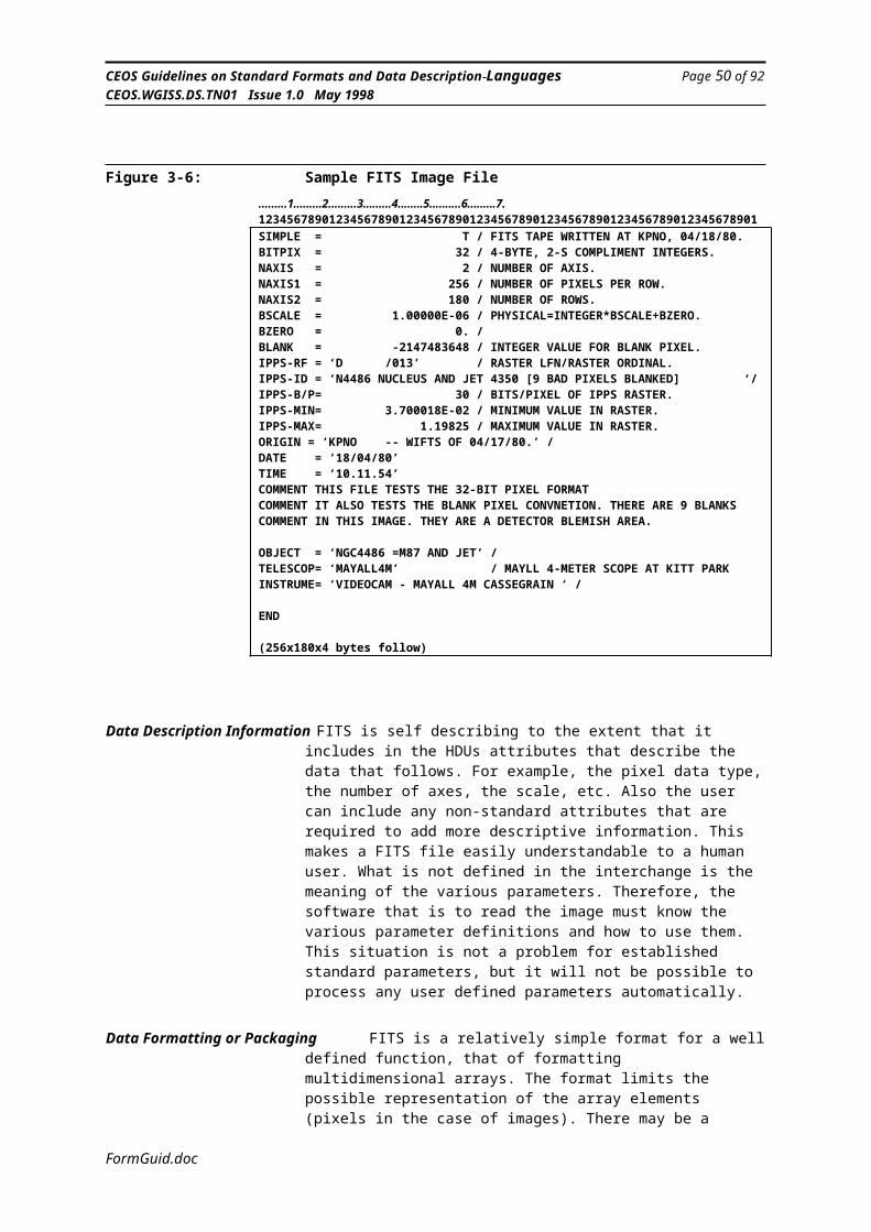
CEOS Guidelines on Standard Formats and Data Description Languages Page 52 of 92CEOS.WGISS.DS.TN01 Issue 1.0 May 1998
3.5 Specifc Formats
There are a number of instrument specific formats which are widely used. These include:
Fast Format This is widely used for Landsat Data.
SKINNYa simplified FastFormat used by NASDA.
AVHRR1bused for the distribution of AVHRR Level 1b data
GRIBGRIB (Grid In Binary) is the World Meteorological Organisation (WMO) standard for gridded meteorological data. Unfortunately it is still not very “standard” as some organisations use their own versions. In particular there are differences between the WMO and ECMWF versions of GRIB.ftp://ncardata.ucar.edu/libraries/grib/
DiMapThis is the name given to the data distribution package for SPOT data. It uses the GeoTIFF format as a basis as is intended to be compatible with the OpenGIS Object Oriented Digital Image model.http://www/spotimage.fr/
FREDFramed Expanded Data (FRED) was defined by MDA for archiving telemetered data at Baseband. It is a satellite specific format and RadarSat and SPOT are currently supported.
GERALDThis is the name given to the process of describing raw SPOT data with the EAST and DEDSL data description languages. Although the technique is generic it has only been applied to SPOT data so far.
Further (now slightly dated) information on other scientific formats can be found at:http://www.cv.nrao.edu/fits/traffic/scidataformats/faq.html
FormGuid.doc

CEOS Guidelines on Standard Formats and Data Description Languages Page 53 of 92CEOS.WGISS.DS.TN01 Issue 1.0 May 1998
4. Data Description Languages
4.1 IntroductionThe current approach for product delivery primarily uses paper documentation for conveying the necessary information concerning the data format. This reliance on natural language descriptions of data formats leads to the development of processing software that is often non-compliant with the expected input format due to ambiguity and inconsistency in the documentation.
Due to the fact that product definition documentation is frequently not kept up to date, systems become reliant upon knowledge passed on by human interaction. This eventually leads to the archived data being of no value, due to the lack of understanding of the data. A number of methods are emerging out of the various standards bodies (i.e., CCSDS, CEOS, ISO) that alleviate the necessity of having paper documentation, by using computer processable formal data description languages. The advantages of these techniques is that it is only necessary to have a single starting point; that of understanding the formal description language, and then from this point all the data stored in the archive or for delivery can be described and used in the future.
If these formal description languages are used to generate the content of the archive and the delivery products, then obviously the description is always up to date and consistent with the products. Another advantage for a generic product delivery system is that new software does not need to be developed each time a new format is required, only the description of the format must be written and then the existing generic software for reading and writing data described in the formal language can be used.
At the simplest level the discipline of producing a formal data description alleviates a number of problems associated with conventional natural language paper documentation, for example, the documentation being incomplete, lost or inconsistent. If used to their full capability they can provide a much higher level of service, such as the understanding of the same data on different machine architectures and the conveyance of the real-world meaning of the data, not just its abstract values.
The task of DDLs can be split into two domains, those that describe the syntax of data and those that describe the semantics of data. The syntax is defined as the physical representation of the data, such as the structure of basic elements, the byte ordering within integers or reals, the bit ordering within bytes, etc. The semantics are defined as the information that gives meaning of the data to the human user, such as units, scaling information, definition of the parameter, etc. It may be that one DDL can perform both tasks, although it is more likely that two languages will be required to fully satisfy both requirements.
If a formal DDL is used to define the syntax of the data product down to the level of each bit and byte, then it means that there is a computer interpretable description of the product. This has the advantage that the description can be used to generate the product, and by definition, the product then must match the formal description. This same description can then be sent with the data product to the user, and the user can use similar software to read the data product, browse the product’s contents, etc.
FormGuid.doc

CEOS Guidelines on Standard Formats and Data Description Languages Page 54 of 92CEOS.WGISS.DS.TN01 Issue 1.0 May 1998
The definition of formal semantic information is not quite so advanced as the syntax description. This is inherent in the fact that semantic information is intended for human understanding, i.e. it requires an intelligence to understand it, and therefore is much more difficult to formalise. Semantic information can also include the possible methods of processing and analysing data, obviously this has a very wide scope for any particular product. Most semantic information such as the real world meaning, can only be conveyed as natural language; obviously this can be ambiguous and therefore misleading unless very carefully defined.
Currently there are a number of DDLs being studied/developed, primarily by the CCSDS. These include EAST (Enhanced Ada Subset), PVL (Parameter Value Language), TSDN (Transfer Syntax Description Notation) and MADEL (Modified ASN.1 as a Data Description Language). FREEFORM is a DDL developed by NOAA NGDC and has some success for the interpretation and visualisation of Earth observation related products. EXPRESS is DDL developed by ISO especially suitable for semantic description and high-level data modelling.
A number of the standards for data formatting that are currently in use do not have separate DDLs. These standards have the data description information embedded within the data itself. For example, HDF (see Section 3.3.2) uses descriptor blocks and tags within the formatted data to indicate what the actual data are. This has the advantage that the description is always available, but the disadvantage that the description must be carried with each instance of the product and therefore is duplicated every time. Also the HDF standard must always be available to look up the standard tags used.
Theoretically, a DDL could be used to define all the formatting standards that are to be supported for delivered data products. This may not be the most efficient method of handling existing established formats that have software available to generate them and could bypass the DDL interpretation, but could be used for any new formats proposed.
There follows a short analysis of a number of currently available or in development DDLs.
FormGuid.doc

CEOS Guidelines on Standard Formats and Data Description Languages Page 55 of 92CEOS.WGISS.DS.TN01 Issue 1.0 May 1998
4.2 ‘Standard’ DDLs
4.2.1 FREEFORM
FREEFORM[28] is a data description language developed by the National Geophysical Data Centre in the USA. Their need for a DDL rose from the fact that they receive data formatted in many ways, concerning various geophysical phenomena, and were spending a great deal of time and effort in converting similar data to the same physical format for ingestion into processing systems.
FREEFORM uses ASCII text files to describe the format of data that is the input format and another text file that describes the desired output format, then standard software can be used to translate the source format to the destination format. Binary and ASCII formatted data can be described, but only a relatively simple level of description is available. For example, only primitive data types are handled; no compound or aggregation of data structures.
The language is especially suited to describing repeated data formats, such as records and entries in ASCII tables. The format description file specifies a name for each element, the start and end byte position within each record, the data type and the precision. Software can then use this description to read the data repeatedly until the end of the file. An example format specification file could be:
/ This is an example format specification file/ Each record in the described file contains a lat and a longlatitude 1 10 double 6longitude 12 22 double 6| | | | | comments| | | | precision| | | type| | end byte| start bytename
This example describes the following input file:
-47.736458 -176.163354 -0.265538 0.777265-28.386695 35.995624 12.575432 -135.773521-83.735428 55.8835434
The data types that are supported are characters, integers of size 8, 16 and 32 bit (signed and unsigned), reals of 7 and 15 bit precision [Are these numbers correct?!] and a couple of special types used to control constant fields in output formats. The same types are supported for both ASCII formatted data and binary data, although the binary data must be in the native physical format of the platform that the supporting FREEFORM software is executing on. For example, it is not possible to use the same data description on a SUN to read binary reals written to a file on a VAX. This is a major limitation of FREEFORM as it makes the data and description platform dependent.
As part of the description language FREEFORM uses two types to indicate special functions; header specifies header field areas at the start of a file that can be ignored or passed over (this is common to many data files); and
FormGuid.doc
CEOS Guidelines on Standard Formats and Data Description Languages Page 56 of 92CEOS.WGISS.DS.TN01 Issue 1.0 May 1998
convert provides a means whereby input data can be converted to a different data type for writing to the output. For example, there are conversions built-in to change the reference and units of latitude and longitude values. The built-in conversions are closely related to geophysical type data, but the user can also supply their own conversions.
There is a graphical display application (GeoVu) that is available for FREEFORM support, including a number of command line utilities. These provide utilities to convert data from one format to another, to display the contents of a data file, whether ASCII or binary, check the syntax of a data file, etc. The software library permits the user to write their own software that will read data described by FREEFORM and output to memory, and hence be able to access the data from their own programs, rather than just converting from one file to another.
In conclusion, FREEFORM has quite simple data description capabilities. It is well suited to regular repeating data records that conform to standard machine representations. A FREEFORM tutorial[28] (there is no formal specification) and the software tools are available from:
http://www.ngdc.noaa.gov/seg/freeform
FormGuid.doc
CEOS Guidelines on Standard Formats and Data Description Languages Page 57 of 92CEOS.WGISS.DS.TN01 Issue 1.0 May 1998
4.2.2 EAST - Enhanced Ada SubSet
EAST[40][41] has primarily been developed by CNES within the CCSDS domain. It is currently in the final review stages of the CCSDS procedures, prior to final issue. As the name implies (Enhanced Ada SubSet), EAST is based upon the Ada language. In fact, EAST is 100% compliant with the Ada syntax. The ‘extended’ aspect is the additional semantics on how it is used.
EAST uses the data declaration aspects of the full Ada language to specify the syntax of data. Due to the fact that the data declarative aspects of Ada are very powerful, it has been found that EAST can describe practically any arbitrary data format; the primary exception being a format that relies upon an algorithm, such as a compressed data format.
EAST supports many basic data types, including characters, integers, reals, enumerations and ASCII encoded numerics. One of the real strengths of EAST is that there is no restriction on the physical representation of reals and integers, the user can define integers to be of any bit size and complement; this facilitates the description of many obscure data formats such as that produced by spacecraft and Earth observation instruments. This applies also to reals, where the size of the components, i.e. mantissa, exponents, sign, etc. can all be specified individually.
For aggregation the full power of Ada records can be used, as can arrays of arbitrary dimensions and Ada subtyping facilities. A particularly powerful feature is the ability to have conditional data structures. This is where a choice of a number of data structures can be defined, the decision made on how to interpret the actual data encountered depends upon the value of a discriminate encountered earlier in the data stream. This is particularly useful for spacecraft data where frequently values in a header field can dictate the type of data that follows.
An EAST description is organised in two units, or packages; the first being the logical package which describes the logical description of all data types used to declare an occurrence of the described data; the second being the physical package that is used to specify the physical representation of basic elements irrespective of their logical formatting, for example, the array index ordering, the octet storage method, the numerics storage method, etc. This distinction into two packages is very convenient when generating data on different machines, as only the physical package needs to be changed, which specifies the different physical representation, and the logical package can stay the same.
Whilst EAST is very powerful at describing the exact syntax of data, it has a number of drawbacks that relate back to its Ada origins. EAST is very verbose in the size of its descriptions. For each element in the data being described, EAST must specify a type definition for that data, and then
instantiate the type to actually define the data. In Ada, this is an advantage as the typing helps readability and reuse. In the data description context, it leads to very long descriptions. Whilst EAST could never be described as being impossible for humans to write unassisted by tools (it is, after all, legal Ada syntax), it is a very complex language for the average scientist to write
FormGuid.doc
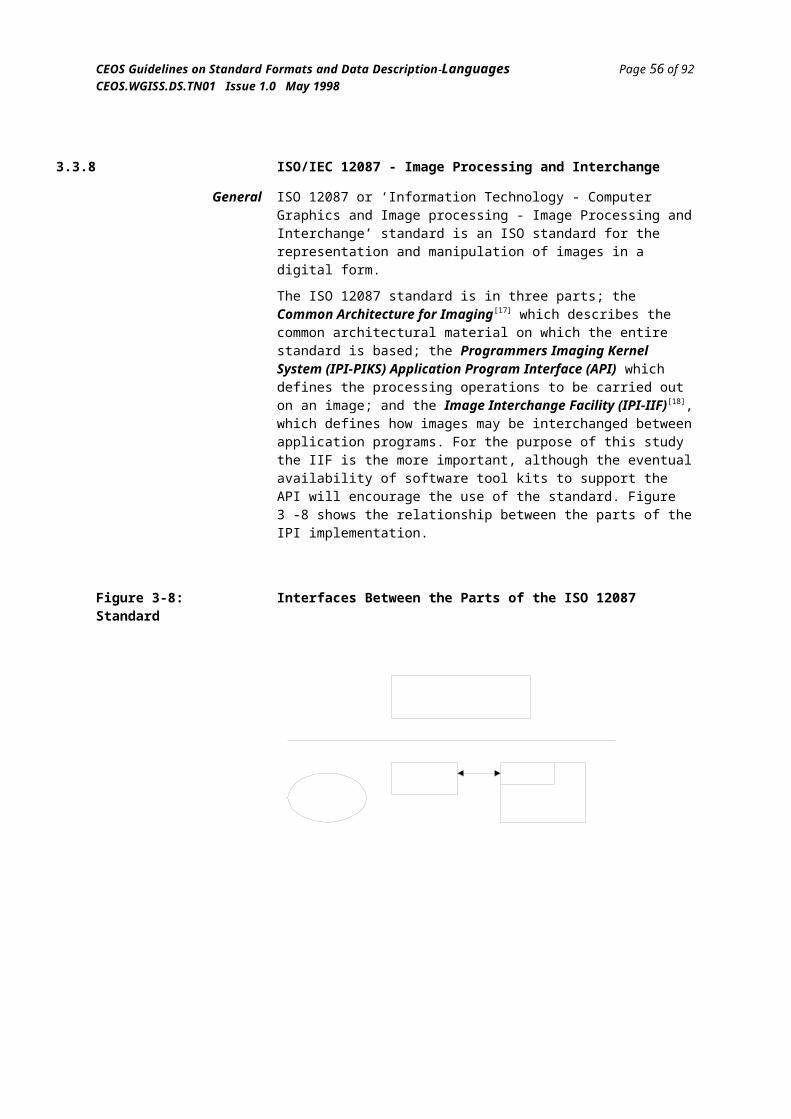
CEOS Guidelines on Standard Formats and Data Description Languages Page 58 of 92CEOS.WGISS.DS.TN01 Issue 1.0 May 1998
freehand. To this end, the language definers at CNES are developing a number of tools to assist in the writing and interpretation of the language.
A tool called OASIS is a graphical tool for defining data structures, showing the dependencies and ranges, etc. and then finally producing EAST listings as an output.
OASIS also allows the import/export of EAST descriptions and through the GUI offers a dynamic link between EAST descriptions and DEDSL semantic descriptions. Import/Export of DEDSL is also available.
OASIS also enables its user to produce data description documents (Word, FrameMaker, Postscript)
The OASIS tool is freely available after a CNES registration (contact [email protected]).
CNES are also developing the following tools (in a prototype form at the moment) :
INTERPRETER : tool that can read data according to an EAST description and permit the user to request the particular value of a named element.
ASCII_DUMP and DATA_VIEWER : two similar tools to display the values of data (as soon as described with EAST). Both are based on the above interpreter. First one produces a line mode DISPLAY, second one is graphical.
ESA are also developing the PAE (Product Access Environnement) that also encapsulates the interpreter to access the data. It offers a lot of functionnalities to parse and display them.
FormGuid.doc
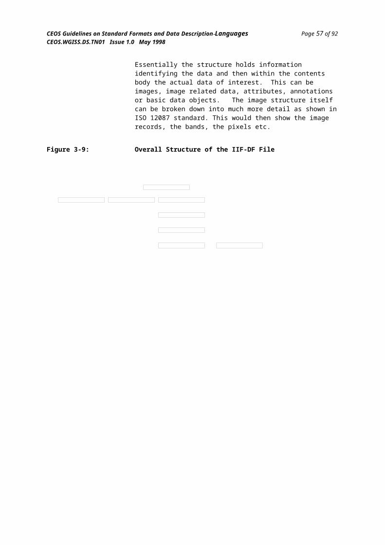
CEOS Guidelines on Standard Formats and Data Description Languages Page 59 of 92CEOS.WGISS.DS.TN01 Issue 1.0 May 1998
4.2.3 MADEL - Modified ASN.1 as a Data Description Language
MADEL is a data description language developed by ESA (again under the auspices of the CCSDS) based upon ISO 8824[19] - Abstract Syntax Description Notation One (ASN.1). ASN.1 was originally designed to describe protocol data units that are interchanged by communication systems. The ASN.1 language describes the exchanged objects at the abstract level, i.e. a field is an integer or real or character string. There is a second standard (ISO 8825[20] -Basic Encoding Rules) that encodes this abstract description into specific bit patterns for interchange. Each entity that makes up the interchanged data is tagged and the receiving end works via the same standard for encoding and tagging as the transmitting end and hence can decode the interchanged objects.
Due to the use of encoding/decoding, it is not necessary for ASN.1 to provide the specification of the physical encoding, so ESA modified the ASN.1 language by providing extensions that permit the description of the data to below the abstract level and permitted the detailed description of the data down to the bit level. This makes the basic encoding rules redundant and they serve no part of the interchange language. The other way that the language had to be modified from the ISO defined ASN.1 was to restrict the number of the types that ASN.1 supports. For example, ASN.1 permits the CHOICE type. This states that the data element is a choice between a number of discrete possibilities. Due to the fact that ASN.1 tagged each possibility, it is possible for the receiver to identify the selected element. As no tagging or encoding is used in MADEL, then this type cannot be supported (otherwise the receiver has no means to identify how the data bytes should be interpreted).
MADEL supports most basic data types such as bit, character, integer, real, etc. and also incorporates powerful aggregation and structuring constructs such as sequences and arrays. MADEL also supports discriminates in the same manner as EAST, although with the added flexibility that a discriminate can be of any type that results in a fixed bit pattern. As stated above, MADEL provides the means to describe integers and reals down to the their exact bit positions, lengths and complements and hence data of arbitrary complexity can be described, including non byte aligned data.
One of the reasons that ASN.1 was selected as a data description language was that it is relatively intuitive to read and hence non-computer scientists can produce it by hand. There are default values for many of the constructs in MADEL, e.g. the size of integers and physical representation of reals. This also makes MADEL easy to read and write. An example of a sample data structure and its corresponding MADEL listing is shown in Figure 4-1:
FormGuid.doc
CEOS Guidelines on Standard Formats and Data Description Languages Page 60 of 92CEOS.WGISS.DS.TN01 Issue 1.0 May 1998
Figure 4-1: A Sample MADEL Description
AS EQ U EN C E
BIN TE G E R
CO C TE T
DS EL E C T o n B
P (B = 1 )IN TEG E R
Q (B = 2 )S EQ U EN C E
XIN TE G E R
YR EAL
R (B = 3 )R EAL
B dictates selec tion m ade by D
Sample_MADEL DEFINITIONS ::=BEGIN A ::= SEQUENCE { B, C, D ) B ::= INTEGER C ::= OCTECT D ::= SELECT B { 1:P, 2:Q, 3:R } P ::= INTEGER Q ::= SEQUENCE { X, Y } X ::= INTEGER Y ::= REALEND
MADEL has been prototyped by ESA, and a MADEL interpreter developed, but the language has never been officially published and is currently only a CCSDS internal work item. This makes the language unsuitable as the baseline for any application requiring data description languages at the present time, although its continued development should be monitored carefully.
FormGuid.doc

CEOS Guidelines on Standard Formats and Data Description Languages Page 61 of 92CEOS.WGISS.DS.TN01 Issue 1.0 May 1998
4.2.4 PVL - Parameter Value Language
Parameter Value Language (PVL)[29][30] is a CCSDS developed language. Its purpose to is provide a simple means whereby values of various data types can be assigned to parameter names so as to convey human and machine interpretable information in a simple manner. PVL is ideal for specifying a number of attributes that apply to a certain data object, whether it be a complete product or an atomic data value
For example, PVL could be used to specify the catalogue information for a data product or experiment measurement. In this context, the receiver of the experiment measurement needs to obtain not only the actual experiment measurement data but also information which puts the data in context, such as the instrument name, the time and date of the measurement, the ambient temperature, the software version used to process the raw reading, etc. To do this, the data generator can define a number of parameters (or attributes) and the possible values; these can then be used as ‘standard attributes’ each time he generates a measurement. For example:
INSTRUMENT = ION_DETECTORMEASUREMENT_TIME = 1995-02-17T15:34:12.2ZAMBIENT_TEMP = 19.7 <degrees>PROCESSING_SOFTWARE_VERSION = 2.4
PVL is written in ASCII and therefore is easy to exchange across heterogeneous platforms and is easy to interpret for both humans and machines. PVL itself does not define any parameter names or particular values. This is up to the application that uses the language, for example a catalogue entry.
The basic statement in PVL is the ‘parameter = value’ statement. Apart from the restriction that the parameter name cannot contain certain punctuation characters, there is no restriction on the format of the parameter name, the value can be of a number of data types, including strings (quoted and unquoted), integers (specified to base 2, 8, 10 or 16), reals, dates and times and two list constructs; a ‘set’ that indicates an list of values where the order is not significant, and a ‘sequence’ that indicates a list of values where the order is significant. It is also possible to follow any value with a units expression. The ranges of values or units expressions permitted are left undefined in PVL, so that an application can impose its own conventions.
PVL also supports the grouping of statements into aggregation blocks using the ‘group’ or ‘object’ statements. There is no distinction defined by PVL on the significance of using the ‘group’ or ‘object’ construct; this is left for the application to define. A simple example of the use of PVL is shown in Figure 4-2, which illustrates the basic features of the language.
FormGuid.doc

CEOS Guidelines on Standard Formats and Data Description Languages Page 62 of 92CEOS.WGISS.DS.TN01 Issue 1.0 May 1998
Figure 4-2: A Sample PVL Listing/* Cluster Satellite/Experiment Details */
MISSION = CLUSTER ;LAUNCHER = ARIANE4 ;LAUNCH_TIME = 1995-10-23T02:23:14Z ;MISSION_DURATION = 748 <days> ;
BEGIN_GROUP = EXPERIMENT_DETAILS ; NAME = ASPOC ; PI_NAME = “Dr. W. Riedler” ; PI_ADDRESS = (“Institute fur Weltraumforschung”, “Graz”, “Austria”) ; DATA_RATE = 22 <Kbps> ;END_GROUP = EXPERIMENT_DETAILS ;
BEGIN_GROUP = EXPERIMENT_DETAILS ; NAME = RAPID ; PI_NAME = “Dr. B. Wilken” ; PI_ADDRESS = (“MPI fur Aeronomie”, “Lindau”, “FRG”) ; DATA_RATE = 1.2 <Kbps> ;END_GROUP = EXPERIMENT_DETAILS ;
As can be seen in the above example, white space and comments can be used freely to enhance readability. PVL is originally based upon a similar language developed by the Planetary Data System within NASA/JPL called ODL (Object Description Language)[31]. ODL is a subset of PVL in that its syntax is the same, but includes additional semantics. For example, the there are differences in the use of the ‘group’ and ‘object’ constructs.
PVL has the disadvantage that, if used to convey large amounts of information, it is very verbose. It is best suited to catalogues, identification information and frequently repeated short object definitions.
There is a PVL toolkit available, developed by NASA/JPL, that parses PVL and builds an internal syntax tree of all parameters and their values. A supplied API can then be used to traverse and query the values stored in the tree. The toolkit can also be used to generate PVL, given parameter names and associated values.
A CCSDS tutorial document (Green Book) can be found on the WWW in the CCSDS document publication section at:
http://www.gsfc.nasa.gov/ccsds/
FormGuid.doc
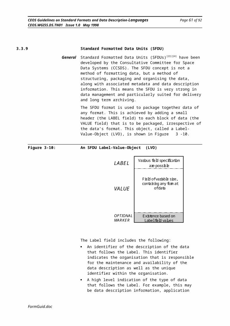
CEOS Guidelines on Standard Formats and Data Description Languages Page 63 of 92CEOS.WGISS.DS.TN01 Issue 1.0 May 1998
4.2.5 DEDSL - Data Entity Dictionary Specification Language
Whenever information is interchanged across an interface, for example, from an Earth observation product archive to the user of that product, there is the requirement to convey to the user enough information so that the user can understand the product completely. Towards this aim, the CCSDS have devised languages to comprehensively describe data so as not to rely upon natural language documentation that are prone to misinterpretation and inconsistencies. To unambiguously describe data, it is necessary to formally describe the syntax of the data interchanged, whether it be at the bit and byte level or by the use of a modern formatting method, such as HDF or GIF. In addition to the syntax of the product, it is necessary to convey the real world meaning (semantics) of each of the elements that make up the product. This is the aim of the CCSDS developed Data Entity Dictionary Specification Language (DEDSL)[43].
Many database schemas include the concept of a Data Entity Dictionary (DED). This usually provides information concerning each element in the database. In many DEDs, the syntax of an element is defined as well as the semantics. The philosophy that the CCSDS have taken is to split the syntax and the semantic definition processes. Data description languages such as EAST and MADEL have been developed to describe the syntax of a data product, whilst the DEDSL has been (or is in the process of being) developed to formally specify the semantics.
The DEDSL uses the Parameter Value Language (PVL) previously defined by the CCSDS to specify attributes which describe the semantics of each data element in a product. The DEDSL is currently only an internal draft within the CCSDS, but a clear understanding has been reached of which attributes are required to define the semantics of an element.
Each element in the product must have a unique name that is specified in the syntax description. This name is then used to identify which element the semantic definition applies to. The other attributes that are required to define the semantics of an element are the real world meaning (in natural language), the units (if applicable), a short description (useful for searching on), an alias in case the element is referred to elsewhere by another name, and a definition of special instances that may be used to convey enhanced semantics to the user, such as the fact that 0° is the ‘equator’ and not just zero degrees. An example of the use of the DEDSL is shown in Figure 4-3. In this example, the DEDSL is used to define the two elements SPACECRAFT_ID and LATITUDE. Note that this example is only illustrative, as the CCSDS DEDSL standard is still only in the late stages of approval and may change before formal issue.
FormGuid.doc

CEOS Guidelines on Standard Formats and Data Description Languages Page 64 of 92CEOS.WGISS.DS.TN01 Issue 1.0 May 1998
Figure 4-3: An Example of the use of the DEDSLBEGIN_GROUP = ENTITY_DEFINITION ; NAME = SPACECRAFT_IDENTIFIER ; SHORT_MEANING = “Spacecraft identifier for ESA missions” ; MEANING = “This is used as the identifier of the spacecraft body and is assigned by the International Spacecraft Identification Body. It is used through out the system to uniquely identify all telemetry and telecommands for any one particular spacecraft”; ALIAS = ( SC_ID, “This is the term used within the NASA ground segment when on co-operative ESA missions” ) ;END_GROUP = ENTITY_DEFINITION ;
BEGIN_GROUP = ENTITY_DEFINITION ; NAME = LATITUDE ; SHORT_MEANING = “North/South position upon the Earth’s Surface”; MEANING = “This is a measurement of the North/South position upon the surface of the Earth. The value is a measurement in angular degrees, where zero is on the equator and the range is from -90 degrees to +90 degrees” ; ALIAS = ( LAT, ”This is the term used within the ground station processing software for saw image collection”) ; UNITS = “degrees” ; SPECIAL_INSTANCE = ( 0, “The Equator” ) ; SPECIAL_INSTANCE = ( +90, “The North Pole” ) ; SPECIAL_INSTANCE = ( -90, “The South Pole” ) ;END_GROUP = ENTITY_DEFINITION ;
The problem of unambiguous description of the semantics of data is common and yet there is currently no standard method of achieving this. Even though the DEDSL is a relatively simple standard, its adoption would greatly improve the documentation of interchanged data. It is designed to be extensible by the inclusion of application specific attributes (for example, a display format attribute for screen representation), and therefore can be used across a wide range of disciplines where definition of information is important but conventionally has been done using natural languages.
FormGuid.doc
CEOS Guidelines on Standard Formats and Data Description Languages Page 65 of 92CEOS.WGISS.DS.TN01 Issue 1.0 May 1998
4.2.6 EXPRESSThe EXPRESS language[32] is an ISO standard information interchange modelling language (ISO 10303 part 11). As an introduction, here follows a brief description of EXPRESS extracted from reference [33]:
“EXPRESS is an object-flavoured information model specification language which was initially developed in order to enable the writing of formal information models describing mechanical products. It is one of the technologies that has been developed as part of the STEP[34] standard for product model data exchange. Although designed to meet the needs of STEP it has also been used in a variety of other large scale modelling applications. Examples include product, process and organisation modelling for concurrent engineering; the specification of information pertinent to data exchange for electronic products; the modelling of petrochemical plants and other aspects of the petrochemical industry; and stock exchange asset management applications, to name just a few. In a different vein it has also been used as a software specification language for CAD packages; to define compiler data structures; and as a neutral data specification language for a variety of database packages.
The purpose of EXPRESS is to describe the characteristics of information that someday might exist in an information base. The process is called information modelling. Information modelling deals with things, what properties those things have (or that we care about), how they behave and how they interact together.
Building an information model is often a prelude to building an information system, including an information base. The information base deals with storing and accessing (values of) things, and other questions of consistency, behaviour, etc. The information system interacts with users, carries out the mission of the system, reacts to and reports problems and deals with other questions of operation and environment.
The main elements of EXPRESS are the schema, the type, the entity and the rule:The schema is a container for the work you do. Much like containers for flour, sugar and so forth. You should plan to use as many different containers (schemas) as you have different kinds of work. Interfacing can be used to import whole schemas or just parts of them into another schema.
Types (or data types) are used to represent value domains. EXPRESS offers the usual assortment of built-in data types such as real and integer numbers, character strings and so on. These data types, however, are unusual because they are not usually bounded. For example, integer numbers in EXPRESS represent a vast domain, which include minus and plus infinity, and real numbers are considered to have infinite resolution. Fortunately, you can build your own data types on top of the build-in ones and put constraints on the domain as necessary.
Entities are the real meat of EXPRESS. They are the things (concepts, etc.) that you really care about. EXPRESS entities have a lot of the characteristics common to Object Oriented Programming (OOP) languages, but strictly speaking, EXPRESS is not an OOP language. The general methods found in OOP languages have been specialised by EXPRESS to deal specifically with derived (calculated) values and constraint management (limited permitted
FormGuid.doc
CEOS Guidelines on Standard Formats and Data Description Languages Page 66 of 92CEOS.WGISS.DS.TN01 Issue 1.0 May 1998
values), but EXPRESS does not offer a generalised method capability otherwise.
Rules allow you to deal with a variety of constraints that are difficult to handle without this special facility. Rules can describe the interaction of different sets of entity values and conditions where only partial coverage of a set of values is involved in a constraint.
There are other aspects of EXPRESS such as constants, functions and procedures and a fairly complete collection of executable statements. However, EXPRESS is not a programming language as it does not deal with input and output, exception handling and other features necessary for that purpose.”
From the basic EXPRESS language there has been a number of additional forms developed: ‘EXPRESS-G’ defines a graphical representation of the EXPRESS language, which includes styles for GUIs and also graphical representation using standard ASCII characters; ‘EXPRESS-I’ can be used to interchange instance data described by an EXPRESS schema.
An example to illustrate the power of EXPRESS is shown below in Figure 4-4. A full explanation of this example follows after the figure.
FormGuid.doc

CEOS Guidelines on Standard Formats and Data Description Languages Page 67 of 92CEOS.WGISS.DS.TN01 Issue 1.0 May 1998
Figure 4-4: An Example of the use of EXPRESSSCHEMA example;
TYPE date = ARRAY [1:3] OF INTEGER;END_TYPE; -- date
TYPE hair_type = ENUMERATION OF(blonde, brown, black, white, bald);
END_TYPE; -- hair_type
ENTITY personSUPERTYPE OF (ONEOF(female, male));first_name : STRING;last_name : STRING;nick_name : OPTIONAL STRING;birth_date : date;children : SET [0:?] OF person;hair : hair_type;
DERIVE
age : INTEGER := years(birth_date); <----- ageINVERSE <----- INVERSE
parents : SET [0:2] OF person FOR children;END_ENTITY; -- person
ENTITY femaleSUBTYPE OF (person);husband : OPTIONAL male;maiden_name: OPTIONAL STRING;
WHERE <----- WHEREw1 : (EXISTS(maiden_name) AND EXISTS(husband))
OR NOT EXISTS(maiden_name);END_ENTITY; -- female
ENTITY maleSUBTYPE OF (person)wife : OPTIONAL female;
END_ENTITY; -- male
RULE married FOR (male, female); <----- RULE(* checks pairwise relationship between spouses *)WHERE
r1 : SIZEOF( QUERY(tf <* female | EXISTS(tf.husband)
AND (tf.husband.wife :<>: tf))) = 0;
r2 : SIZEOF( QUERY(tm <* male | EXISTS(tm.wife)
AND (tm.wife.husband :<>: tm))) = 0;
END_RULE; -- married
FUNCTION years(past : date): INTEGER; <----- years(* this function calculates the number of years
between the past date and the current date *)END_FUNCTION; -- years
END_SCHEMA; -- example
FormGuid.doc
CEOS Guidelines on Standard Formats and Data Description Languages Page 68 of 92CEOS.WGISS.DS.TN01 Issue 1.0 May 1998
This example defines that a person must be either male or female. Every person has some defining characteristics, such as first and last name, date of birth, etc. and also they may have zero or more children (which are also people). A male may be married to a female and vice-versa. The intent of the RULE is to ensure that if a particular male has a particular female for his wife, then that particular female has the same male as a husband.
There is one particular piece of information about females that does not apply to males; a female may have a maiden name. The WHERE clause is used to specify that a female may have a maiden name if she has a husband. Note that it does not say that she must have a maiden name if she is married (some wives do not take their husband’s last name).
The AGE of a person is a derived attribute that is calculated by the function YEARS which determines the number of years between the date input as a parameter and the current date. A person has an INVERSE attribute which relates people who are children to their parents.
EXPRESS has a significant user community, annual user group conferences, an e-mail users group, and a large body of available software [35], some of it proprietary and other public domain. This software includes utilities for graphically entering schemas, generating and checking EXPRESS and compiling or converting EXPRESS to regular programming languages, such as C++, for accessing data.
EXPRESS documentation in available on the Internet via the SREP Homepage:
http://www.steptools.com/
FormGuid.doc

CEOS Guidelines on Standard Formats and Data Description Languages Page 69 of 92CEOS.WGISS.DS.TN01 Issue 1.0 May 1998
4.3 DDL Summary ComparisonThis section provides a summary of the suitability of the various DDLs against a number of criteria that are important to the engineer requiring to select a DDL for a particular task. Many of the DDLs have similar capabilities, but the techniques used to implement the capabilities can have a major effect on how easy the DDL would be to use in practice. Therefore, in Table 4-1 some of the capabilities are indicated as a Yes (y) or No (n), whilst others get from zero to 3 tick marks to indicate suitability to task; the former indicating the capability is not supported at all, the latter indicating full support by design (a ‘-’ indicates that the capability is not applicable):
Table 4-1: Data Description Language Comparison
Capability FREEFORM
EAST MAD-EL
PVL DED-SL
EXPR-ESS
Syntax description
n n
Basic types
- -
Arbitrary length basic types n y y n - -
Aggregation structures n y y y - -
Discriminates for real-time selection n y y n - -
Arrays n y y n - -
Custom physical representation n y y n - -
Structured logic, i.e. do-while, if-then-else n y n n - -
Semantic description n n n n y y
Basic semantic information, i.e. meaning, units, etc.
- - - - y n
High-level data modelling - - - - n y
Logical relationships between data elements - - - - n y
Software support n n
DDL generation n n n n
DDL interpretation n n n
Off-the-shelf applications n n n n
Usability without software tools
Platform architecture independent
Human readability
Current widespread use n n
Documentation available/readability n
Long-term stability
FormGuid.doc

CEOS Guidelines on Standard Formats and Data Description Languages Page 70 of 92CEOS.WGISS.DS.TN01 Issue 1.0 May 1998
As the concept of formal data description languages is relatively new and many of the languages discussed above are still in their prototype stages, there are not currently many ‘real’ systems that demonstrate their use. The only languages that do have an established base are PVL, EXPRESS and FREEFORM; these have been used extensively in the space industry, manufacturing and Earth observation communities respectively.
FormGuid.doc

CEOS Guidelines on Standard Formats and Data Description Languages Page 71 of 92CEOS.WGISS.DS.TN01 Issue 1.0 May 1998
5. Additional Information
Some additional information is provided in these sections for the two most widely used format systems in the field of Earth observation.
5.1 Heirarchical Data Format (HDF)
5.1.1 Introduction
The Hierarchical Data Format (HDF) was developed by the National Center for Supercomputing Applications (NCSA) Software Development Group. The HDF development effort originated in response to a need for storing different types of scientific data generated on different types of computers. HDF met this need by allowing scientists to share data files across different computers, access the same data files using different software applications, and store different types of data in the same file.
HDF provides several different “data models” which can be used to store data products. Each data model has an associated Application Programming Interface (API) which facilitates the reading and writing of data stored using that data model. The data models currently provided by HDF include Scientific Data Sets (SDS), Raster Image Sets (RIS), Vdatas, and Vgroups.
The HDF software library and documentation are freely available via anonymous ftp. The Internet address of the server is:
ftp.ncsa.uiuc.edu
The HDF software library could also be procured using the URL:
ftp://ftp.ncsa.uiuc.edu/HDF/
The HDF Information Server:
http://hdf.ncsa.uiuc.edu
5.1.2 Scientific Data Set (SDS)
Many Earth science data sets can be conceptualized as multi-dimensional arrays. The general concept of a multi-dimensional array is fairly simple: an n-dimensional array of values, all of which share the same data type and, usually, the same engineering units and data source. Figure 5-1 shows a conceptual view of a multi-dimensional array containing integer values. This example shows a 3-dimensional array.
FormGuid.doc

CEOS Guidelines on Standard Formats and Data Description Languages Page 72 of 92CEOS.WGISS.DS.TN01 Issue 1.0 May 1998
Figure 5-1: A 3-dimensional Multi-dimensional array with dimensions 4 by 3 by 9
8 7 4 6 3 2 4 6 77 5 9 3 0 5 4 1 25 8 6 0 2 4 1 8 8
8 9 6 4 8 3 5 1 27 5 9 3 0 5 4 1 95 8 6 0 2 4 1 8 6
5 3 7 4 8 2 9 1 47 5 9 3 0 5 4 1 35 8 6 0 2 4 1 8 5
3 5 4 8 2 6 3 2 97 5 9 3 0 5 4 1 45 8 6 0 2 4 1 8 7
In HDF, the multi-dimensional array is instantiated as a Scientific Data Set (SDS) which consists of the n-dimensional array along with some bookkeeping information such as the data type, rank (number of dimensions), and dimensions of the array. For example, the data product shown in figure 4-1 would have data type “uint8”, “uint16”, or “uint32” (an unsigned 8-, 16-, or 32-bit integer), a rank of 3, and dimensions of 4,3,9 (in “C” order).
The SDS APIs (there are currently two versions of the SDS interface) provided with HDF give application programmers the ability to create multi-dimensional arrays, read or write all or part of their data, and assign the multi-dimensional array certain metadata. The newer SDS API (sometimes called the SD interface) available since HDF 3.3 allows added flexibility in dealing with multi-dimensional arrays. Specifically, it allows more than one SDS to be active at one time, it provides for one “unlimited” dimension for each SDS (along which data “records” may be appended indefinitely), and it provides a facility for defining general attributes for individual multi-dimensional arrays and for the entire file.
An example of the use of the SDS can be found in the data product of the Pathfinder AVHRR Land group. This product consists of 12 SDSs each with the dimensions 5004 by 2168. The product was implemented as 12 separate SDSs because each “layer” of the product represents a different science parameter with different metadata values. In addition, 3 of the layers use 8-bit integers while the remaining 9 layers use 16-bit integers. The product has been implemented in HDF version 3.2, release 4 SDS API. Figure 5-2 shows a diagram representing a portion of the Pathfinder AVHRR Land data product.
Figure 5-2: Diagram of Pathfinder AVHRR Land Data product showing 4 of the 12 layers
Use Word 6.0c or later to
view Macintosh picture.
FormGuid.doc
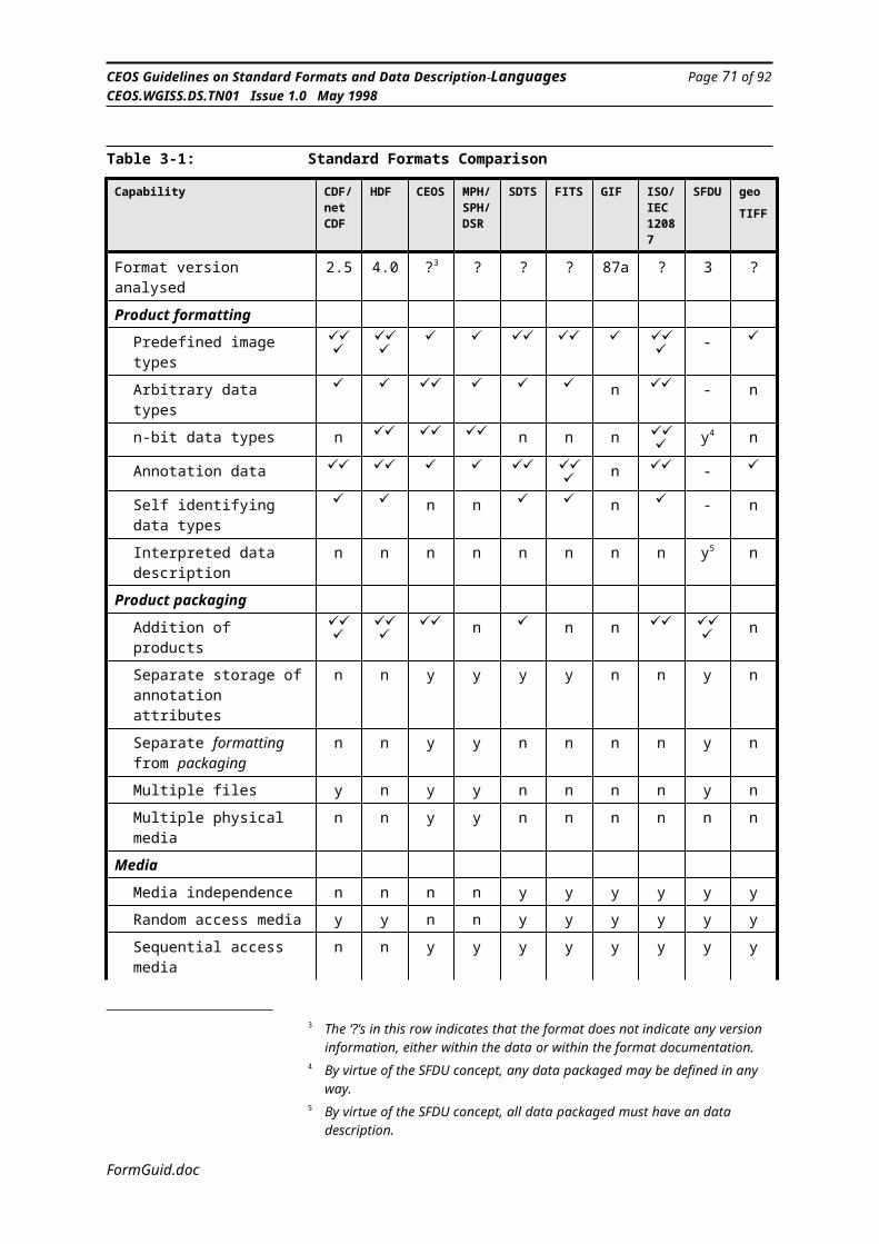
CEOS Guidelines on Standard Formats and Data Description Languages Page 73 of 92CEOS.WGISS.DS.TN01 Issue 1.0 May 1998
Raster Image and Palette The Raster Image consists of a two-dimensional rectangular array of n-bit numbers and a small amount of bookkeeping information such as the dimensions of the array and, possibly, a color lookup table or palette. In HDF, the Raster Image is instantiated as a Raster Image Group (RIG). There are two possible types of RIGs in HDF: 8-bit and 24-bit. Figure 5-3 shows a diagram of a Raster Image.
Figure 5-3: A Raster ImageUse Word 6.0c or later to
view Macintosh picture.
An 8-bit RIG consists of an n by m array of 8-bit numbers, a dimension record stating the values of n and m, and an optional palette. Additionally, the implementor has the choice of several compression algorithms to apply to the image: Run-Length Encoding (RLE) and JPEG.
A 24-bit RIG is slightly more complex than the 8-bit RIG. It contains an n by m by 3 array of 8-bit numbers, and a dimension record stating the values of n and m. The third dimension comes from splitting the 24-bit numbers into 3 8-bit numbers, representing the values of red, green and blue, respectively, for each pixel. With a 24-bit raster, the implementor also has the choice of interlacing schemes (by pixel, scan line, or color plane) and several types of compression.
FormGuid.doc
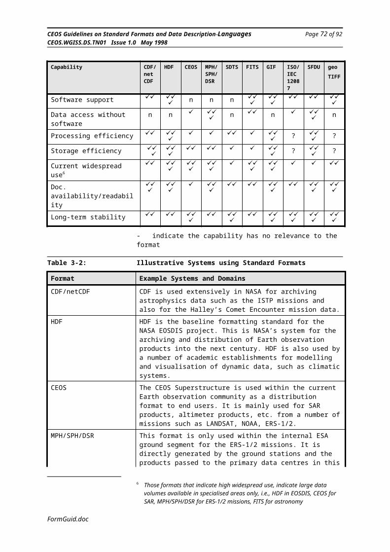
CEOS Guidelines on Standard Formats and Data Description Languages Page 74 of 92CEOS.WGISS.DS.TN01 Issue 1.0 May 1998
Figure 5-4: NSIDC SSM/I Data Product
Use Word 6.0c or later to
view Macintosh picture.
An example of an implementation using raster images can be found in the SSM/I data products produced by NSIDC. In this implementation, each file contains a single 8-bit RIG with a palette. Figure 5-4 shows a diagram of such a data product
5.1.3 HDF Vset
The term “HDF Vset” is used to refer to a group of C and FORTRAN callable functions that make up one of the HDF API’s. Although Vset is sometimes considered to be a single API, it is best conceptualized as containing two separate data models: the Vgroup and the Vdata.
A Vgroup is simply a set of HDF data objects that have been grouped together and given, optionally, a name and a class. The name is intended to identify a specific Vgroup, while a class is intended to allow the definition and naming of different sets of Vgroups. A Vgroup may contain any number of HDF data objects, including Vdatas and other Vgroups.
A Vdata consists of a set of user-defined fields (each of which is given a name and a data type) which form a record. There may be any number of records in a single Vdata. The Vdata, as a whole, may optionally be given a name and a class, similar those for the Vgroup. Setting up a Vdata is a two step process. First, the fields must be defined by a series of function calls (one per field) giving each field a name and a data type. Then, the actual data can be written to the Vdata either one record at a time or in groups of records.
FormGuid.doc

CEOS Guidelines on Standard Formats and Data Description Languages Page 75 of 92CEOS.WGISS.DS.TN01 Issue 1.0 May 1998
Figure 5-5: Data organization in V Group and UNIX file system
Use Word 6.0c or later to
view Macintosh picture.
An example of an implementation using Vsets can be found in the point data produced by NSIDC.
5.1.4 Software Tools
This section lists the currently available tools and utilities that can handle HDF files. For the purposes of this document, it is convenient to divide HDF related tools into four categories:
HDF utilitiesNCSA visualization and analysis toolsOther public domain visualization and analysis toolsCommercial visualization and analysis tools
FormGuid.doc
CEOS Guidelines on Standard Formats and Data Description Languages Page 76 of 92CEOS.WGISS.DS.TN01 Issue 1.0 May 1998
Table 5-1: HDF Utilities
Utility Description Platforms Supported
hdf24to8 24-bit Raster Image Sets to 8-bit Raster Image Sets
All HDF-supported platforms
hdfed Low-level file browse with limited editing capabilities
"
hdfrseq Play an animation sequence through NCSA/BYU Telnet
"
jpeg2hdf Ingest raw JPEG compressed image as a compressed RIS
"
r8tohdf Ingest raw 8-bit image as 8-bit Raster Image Set
"
vmake Create Vset structures from ASCII text "hdf2jpeg Output Raster Image Set as raw JPEG image "hdfls List contents of an HDF file (tags and
reference numbers)"
hdftopal Ouput HDF palette as raw palette "make24 "ristosds Convert Raster Image Sets to Scientific
Data Sets"
vshow Display the contents and structure of Vgroups and Vdatas
"
hdfcomp Compress Raster Image Sets "hdfpack Free unused space in file; join linked blocks "hdftor8 Output 8-bit Raster Image Set as raw 8-bit
image"
paltohdf Ingest raw palette as HDF palette "vcompat Update Vset 1.0 files to Vset 2.0 and higher "
FormGuid.doc
CEOS Guidelines on Standard Formats and Data Description Languages Page 77 of 92CEOS.WGISS.DS.TN01 Issue 1.0 May 1998
Table 5-2: NCSA Tools
Tool Description Platforms Supported
Mosaic Distributed hypermedia data discovery and retrieval
SGI Iris/Indigo, Sun SPARC, DECstation, DEC Alpha, IBM RS/6000
Collage Collaborative image/animation display and processing
SGI Iris/Indigo, Sun SPARC, DECstation, DEC Alpha, IBM RS/6000, Macintosh, PC
Image/X Image Standalone image/animation display and processing
SGI Iris/Indigo, Sun SPARC, DECstation, IBM RS/6000, Cray, Macintosh
X Data Slice Standalone 3-D data set display
SGI Iris/Indigo, Sun SPARC, DECstation, DEC Alpha, IBM RS/6000, Cray
Datascope Standalone 2-D data set display and processing
Macintosh
Reformat/ Xreformat
Conversion of data into HDF SGI Iris/Indigo, Sun SPARC, DECstation, DEC Alpha, IBM RS/6000
Table 5-3: Other Public Domain Tools
Tool Description Developer
Contact Phone
HDF Browser supports opening and viewing HDF files
Fortner Research
Ted Meyer (703) 478-0181
FREEFORM Data description language and related ingest/conversion utilities
NGDC Ted Habermann
(303) 497-6472
GeoVu Data manipulation and display software for FREEFORM data.
NGDC Ted Habermann
(303) 497-6472
AOIPS Image processing GSFC Chris Kummerow
(301) 286-6299
LinkWinds Image analysis JPL Allan Jacobson
(818) 354-0693
SEAPAK Ocean data analysis GSFC Jim Firestone (301) 286-7108
WIGSS Data analysis JPL Andy Pursch (818) 354-8480
GRASS Geographic Information System with image processing functions
US Army CERL
Mike Shapiro (217) 352-6511
FormGuid.doc
CEOS Guidelines on Standard Formats and Data Description Languages Page 78 of 92CEOS.WGISS.DS.TN01 Issue 1.0 May 1998
Table 5-4: Commercial Tools
Tool Vendor Contact Phone
AVS AVS, Inc John Sheehan (617) 890-4300Data Explorer IBM Kevin
McAuliffe(914) 784-5021
IDL RSI Donna Brown (303) 786-9900IRIS Explorer SGI Joe Rogers (301) 572-1675PV-Wave/IMSL Visual Numerics Scott Grayell (303) 530-9000PCI PCI RS Corp. Ed Jurkevics (703) 243-3700Noesys Fortner Research,
PLCTed Meyer (703) 478-0181
Spyglass Fortner Research, PLC
Ted Meyer (703) 478-0181
Wavefront Wavefront Tech Tim Bleakley (404) 698-9524
FormGuid.doc
CEOS Guidelines on Standard Formats and Data Description Languages Page 79 of 92CEOS.WGISS.DS.TN01 Issue 1.0 May 1998
5.1.5 HDF Advantages
The HDF library is supported on multiple platforms. For data centers distributing data, this is a big advantage, particularly if they have to support diverse user communities using multiple types of platforms, since the data will be more portable. The HDF software is freely available for users.
The format is also supported by a number of data processing software packages.
FormGuid.doc
CEOS Guidelines on Standard Formats and Data Description Languages Page 80 of 92CEOS.WGISS.DS.TN01 Issue 1.0 May 1998
5.2 CEOS SAR FormatsThis section gives some background to the development of the CEOS superstructure and describes its use in the distribution of data for recent satellite SAR missions.
SAR Data products may be in the form of framed scenes or continuous strip data (swath), either as uncompressed signal data, or partially processed signal data, fully processed image data, geocoded products with or without digital elevation correction and mosaiked geocoded products.
The LGSOWG (Landsat Ground Station Operators Working Group) developed and maintained a standard for a “Family of Formats” for international exchange of remotely sensed data and processed products on computer compatible tape (CCT). With the successful launch of Landsat-4 and indications of the high quality data from its sensor, the Thematic Mapper (TM), the LTWG (Landsat Technical Working Group) addressed specific format standardization issues. In light of the interest in, and potential value of TM imagery, the LTWG defined certain fixed record, file and volume formats and recommended their use by all TM data processing and tape producing facilities. The standard includes a set of records which forms a superstructure for all data formats of the family and guidelines/directives for organizing data within volumes, files and data records. The objective is to include in each tape format sufficient information (via standard superstructure records) to identify and locate data within the tape, and sufficient common conventions to promote systematic compatibility among the various tape products.
The family of formats was initially maintained by the LTWG, but this function was passed to the Committee on Earth Observation Satellites (CEOS) Working Group on Data ( CEOS-WGD ). Working in parallel with the LGSOWG LTWG, and encouraged by the success of the international TM format, the CEOS-WGD defined a format to be used internationally for the distribution and exchange of radar data in both video-signal and processed image data form.
SAR data products are organized into logical volumes, which can span one or more physical volumes. The simplest products are those that occupy only one physical volume. However, the superstructure concepts used in the standard format family conveniently handle multiple physical volumes, and permit the SAR logical volume data to be split across physical volumes, between files or even between data records within the files. The “SAR Logical Volume” encompasses all SAR data modes. This includes signal data obtained directly from the sensor (Raw), image data, enhanced SAR data, synchronized information from the sensor platform, downstream telemetry with associated georeferencing data and facility related parameters, such as correction tables or matrices. The logical volume is structured using the following classes of files:
FormGuid.doc
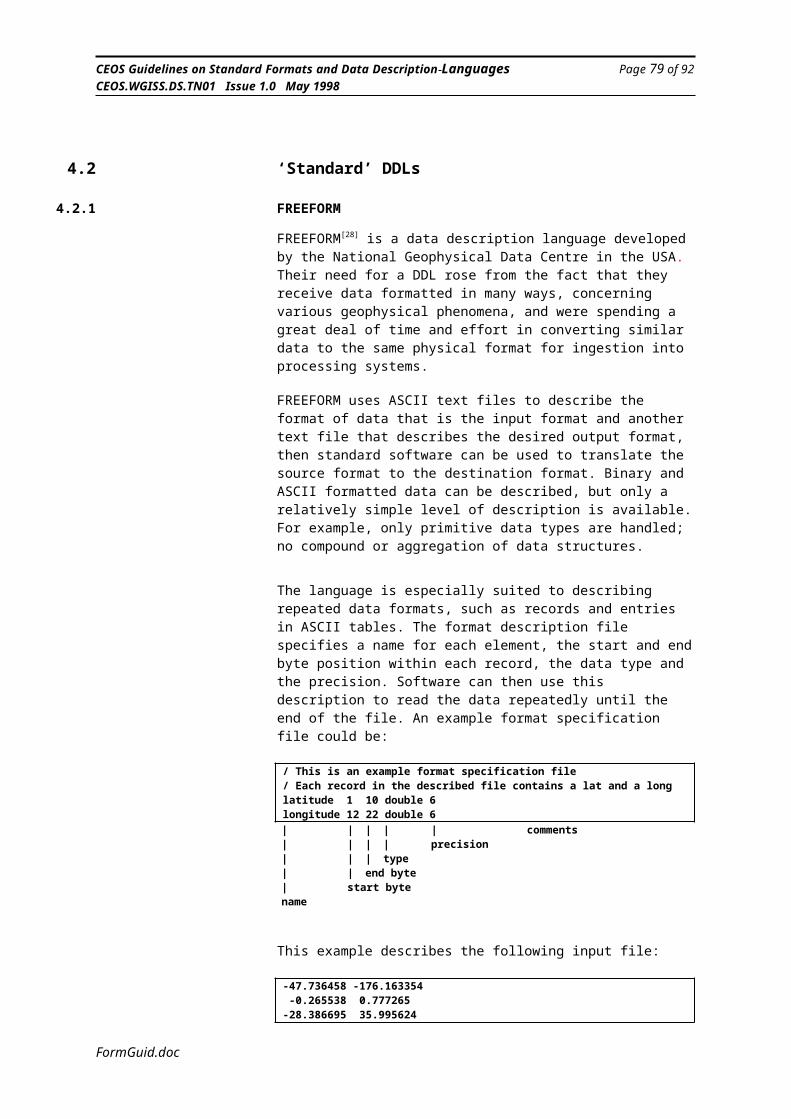
CEOS Guidelines on Standard Formats and Data Description Languages Page 81 of 92CEOS.WGISS.DS.TN01 Issue 1.0 May 1998
* VOLUME DIRECTORY FILE* SARLEADER FILE * IMAGERY OPTIONS FILE * SARTRAILER FILE * NULL VOLUME DIRECTORY FILE
A logical volume set consists of a multiple of the first four files above and is terminated by a Null Volume Directory File.
The Volume Directory File is the first file of the SAR logical volume and consists of a volume descriptor record, file pointer records and text records. The purpose of this file is to identify the logical volume and to specify its structure as it relates to the physical volume.
The SARleader File contains auxiliary information pertaining to the data, such as platform geometry, data quality, radiometric compensation, etc.
The Imagery Options File contains the SAR data (either signal data or processed data). The organisation of the imagery file may be “Band Sequential” (BSQ), where the file contains image data for one spectral band only, “Band Interleaved by Line” (BIL) or “Band Interleaved by Pixel” (BIP), where the file contains data for one or more channels.
The SARtrailer File contains detailed processing parameters, calibration data, facility related data etc.
The records contained in each of the files are shown in Table 5.5.
FormGuid.doc
CEOS Guidelines on Standard Formats and Data Description Languages Page 82 of 92CEOS.WGISS.DS.TN01 Issue 1.0 May 1998
Table 5-5: CEOS Format File Structure OverviewVOLUME DIRECTORY FILE Volume descriptor record File pointer records Text record
SARLEADER FILE SAR leader file descriptor record Data set summary record Map projection data record Platform position data record Attitude data record Radiometric data record Radiometric compensation record Data quality summary record Data histograms record Range spectra record Digital elevation model descriptor record
SAR DATA FILE Image options file descriptor record Signal data records or processed data records
SARTRAILER FILE SAR trailer file descriptor record Detailed processing parameters record Calibration data record Ground control points descriptor record Facility related data record
NULL VOLUME DIRECTORY FILE Null volume descriptor record
FormGuid.doc

CEOS Guidelines on Standard Formats and Data Description Languages Page 83 of 92CEOS.WGISS.DS.TN01 Issue 1.0 May 1998
The following list identifies recent SAR missions that provide data using the CEOS SAR Format.
ERS (European Remote Sensing Satellite)
The first European Remote Sensing Satellite ERS-1 was launched by the European Space Agency ESA in July 1991. ESA’s second Remote Sensing Satellite ERS-2 was launched in April 1995. The payload of both satellites consists of active and passive sensors. Both satellites contain the Active Microwave Instrumentation (AMI), operating in C-Band either as Synthetic Aperture Radar (SAR) or as Wave-Scatterometer and simultaneously as Wind-Scatterometer.
All ERS SAR data products are delivered in the CEOS SAR Formats, with Volume Directory File, SAR Leader File, Imagery Options File and Null Volume Directory. A SAR Trailer File is not used.
ERS SAR products format descriptions can be found in the annexes of:
ERS-1 SAR Products Computer Compatible Tape Format Specifications, ER-IS-EPO-GS-0506Is/Rev 2/0, EARTHNET PROGRAMME OFFICE.
ANNEX A: ERS1.SAR.RAW CCT FORMAT DEFINITION ANNEX B: ERS1.SAR.FDC CCT FORMAT DEFINITION ANNEX C: ERS1.SAR.SLC CCT FORMAT DEFINITION ANNEX D: ERS1.SAR.PRI CCT FORMAT DEFINITION ANNEX E: ERS1.SAR.GEC CCT FORMAT DEFINITION ANNEX F: ERS1.SAR.GTC CCT FORMAT DEFINITION
These documents are available on the WWW through the ESA Guide and Directory Service at: http://gds.esrin.esa.it/
SIR-C/X-SAR (Spaceborne Imaging Radar- C and X- Synthetic Aperture Radar)
SIR-C/X-SAR flies on the Space Shuttle and is part of NASA’s Mission to Planet Earth. The instrument uses three microwave wavelengths: L-band (24 cm), C-band ( 6 cm), and X-band ( 3 cm). It flew on space shuttle Endeavour on mission STS-59 April 9-10, 1994 and on mission STS-68 September 30-October 11, 1994.
The SIR-C was developed by NASA’s Jet Propulsion Laboratory, the X-SAR space segment was developed by Dornier and Alenia Spazio under contract of the German space agency, Deutsche Agentur für Raumfahrtangelegenheiten (DARA), and the Italian space agency, Agenzia Spaziale Italiana (ASI) with the Deutsche Forschungsanstalt für Luft- und Raumfahrt e.V. (DLR), as the major partner in science and technical advisory. In the X-SAR ground segment DLR and ASI are sharing mission operations, calibration and data processing of X-SAR.
The SAR data are delivered to users in CEOS SAR Format and the format descriptions can be found in:
http://www.dfd.dlr.de/xsar/DLRDOCS.html
FormGuid.doc
CEOS Guidelines on Standard Formats and Data Description Languages Page 84 of 92CEOS.WGISS.DS.TN01 Issue 1.0 May 1998
JERS-1 (Japanese Earth Resources Satellite)
JERS-1 is an Earth Observation Satellite whose mission is focused on Earth resources, geology, agriculture, forestry, land use, sea ice monitoring and coastal monitoring. JERS-1 contains two instruments - a Synthetic Aperture Radar (SAR) and an Optical Sensor (OPS). The JERS-1 SAR operates in L-Band and the swath width is 75 km, and there is an onboard Mission Data Recorder (MDR) which allows it to collect data even when a ground station is not in view. The satellite was launched by the National Space Development Agency of Japan (NASDA) on an H-I rocket on Feb. 11, 1992, and the Earth Observation Center (EOC) receive and process the data.
The distributed SAR products conform to the CEOS SAR format standard and further details can be found in:
User’s Guide for JERS-1 SAR Data Format. 1st Edition, National Space Development Agency of Japan
JERS-1 SAR CCT FORMAT, 1991.12.20, Draft Version, NASDA/EOC
JERS-1 Verification Mode Processor, Product Specification, Ref: EA-IS-50-4576, Issue/Revision 1/1, Sep. 04,1992, MDA
http://www.restec.or.jp/
RADARSAT
The RADARSAT Earth observation satellite provides an operationally-oriented radar satellite system capable of timely delivery of large amounts of data. It was developed under the management of the Canadian Space Agency (CSA) in co-operation with NASA/NOAA, provincial governments, and the Canadian private sector. The Canada Centre for Remote Sensing (CCRS) receives the data at Gatineau, Québec and Prince Albert, Saskatchewan ground receiving stations.
RADARSAT was launched in November 1995. It has a single frequency, C-Band SAR, with unique ability to shape and steer its radar beam over a 500 kilometre range. Users will have access to a variety of beam selection that can image swath from 35 kilometres to 500 kilometres with resolution from 10 meters to 100 meters respectively. Incidence angles will range from less than 20 degrees to more than 50 degrees.
All SAR data products will be delivered in the CEOS SAR Format with Volume Directory File, SAR Leader File, SAR Data File, SAR Trailer File, and Null Volume Directory File, where some of the records within the files are optional for some products.
Further information can be found in:
RADARSAT Illuminated: Your Guide to Products and Services, Preliminary Version 07/95, RADAR SAT International.
http://www.rsi.ca/frame.htm
FormGuid.doc
CEOS Guidelines on Standard Formats and Data Description Languages Page 85 of 92CEOS.WGISS.DS.TN01 Issue 1.0 May 1998
6. Other Aspects
6.1 Format Translation
1. NASA and ESA jointly implemented the translation software for the SeaWiFS Level 1A LAC data. SeaWiFS Level 1A LAC data in the CEOS Format was translated to the HDF format as incorporated by the SeaWiFS project of NASA. The SeaWIFS project of NASA used the HDF3.3r3 Version for the translation effort.
The metadata and data values were first mapped from the CEOS Format to the HDF format. Once the mapping was done, the metadata was stored as global or local attributes in the HDF file. Certain metadata was also stored as Scientific Data Sets (SDS). The actual imagery data was stored as a single three dimensional SDS. This SDS contained all the bands of the SeaWiFS data.
During the translation process to HDF, all the CEOS superstructure specific data were ignored. This was done since, in the HDF format, CEOS format specific data would be superfluous. A design document is available from R. Suresh at NASA (email:[email protected])
2. NASDA is working on a number of translation projects involving the CEOS Format and HDF. The data sets include ADEOS - OCTS (Ocean Color and Temperature Scanner), AVNIR (Advanced Visible and Near Infrared Radiometer) data, and JERS-1 - SAR and OPS data. NASA will participate in some of these activities. For more information on these activities contact Mr. Suzuki at NASDA (email:[email protected]) or R. Suresh at NASA (email:[email protected])
3. NASDA is also working on:
a) translation to and from the SKINNY file format developed by NASDA. SKINNY is similar to the EOSAT FAST format. It has a smaller data size than the CEOS Format and does not have header and trailer information within the image data.
b) GRIB to HDF Conversion for Meteorological Grid Point Value Data (GPV). Meteorological grid point data (e.g., pressure, temperature etc.) is required for ADEOS OCTS data processing. NASDA will receive this dataset in GRIB format and convert it to HDF format to make it easier to use.
c) HDF Conversion for Buoy Data: Buoy data is required for sea truth data for OCTS Cal/Val activities. The data will be written into the HDF format to make it compatible with other datasets.
FormGuid.doc
CEOS Guidelines on Standard Formats and Data Description Languages Page 86 of 92CEOS.WGISS.DS.TN01 Issue 1.0 May 1998
7. Conclusions and Recommendations
As stated in the introduction, format systems have different characteristics and a single format standard is not capable of satisfying all formatting needs. The two most widely used generic formats in Earth Observation are the CEOS Superstructure Format (usually referred to as simply the CEOS Format), HDF (or more correctly HDF-EOS), and, more recently, GeoTIFF.
The advantage of HDF is its strong software support and the availability of data processing tools which can handle the format directly. HDF is therefore very suitable for distributing data to end-users. The format is less suitable for long-term archiving of data because of its dependence on an evolving software library for reading and writing the data.
The CEOS Format provides a standard superstructure for organising files on media and a semi-generic format adapted for various classes of instrument. It is particularly widely used for SAR data. Software to read the format and understand the syntax of the data records can usually be obtained from the data suppliers.
On the commercial side, the use of GeoTIFF is increasing. Its use is likely to become widespread in area of optical imagery and GIS.
The use of machine readable data description languages (DDLs) to describe the format of data allows data producers a lot of flexibility in how the data is written without losing the generic nature of the software tools required to read and interpret the data. The capability of data description languages have so far been limited, but more powerful languages are being developed and more sophisticated software tools are becoming available.
The simple DDL Freeform with its associated GeoVu software is good for handling simple datasets, particularly of a tabular nature. The EAST DDL, which is due to become an ISO standard, offers the capability of handling complex datasets down to the bit level, but at the expense of increased complexity. The associated software tool, OASIS, eases the use of EAST considerably.
The importance of machine-readable semantic description languages is also likely to increase in the future. Currently, the only real contender is the Data Entity Dictionary Specification language (DEDSL). It is currently used within the Catalogue Interoperability Protocol (CIP) and within the International Directory Network (IDN). It is also on its way to becoming an ISO standard.
FormGuid.doc
CEOS Guidelines on Standard Formats and Data Description Languages Page 87 of 92CEOS.WGISS.DS.TN01 Issue 1.0 May 1998
FormGuid.doc
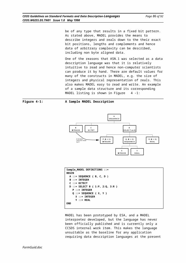
CEOS Guidelines on Standard Formats and Data Description Languages Page 88 of 92CEOS.WGISS.DS.TN01 Issue 1.0 May 1998
Appendix A. References
Ref Title Ref Ver Date Author1 Procedures Manual for the Consultative Committee for
Space Data SystemsCCSDS A00.0-Y-6 6 May 1994 CCSDS
2 CDF User’s Guide 2.5 10-Jan-95 NASA/NSSDC
3 CDF ‘C’ Reference Manual 2.5 10-Jan-95 NASA/NSSDC
4 External Data Representation (XDR) RFC 1014
5 Getting Started with HDF 3.2 May-93 NCSA
6 Untitled document on ‘CEOS Format’ CCRS
7 ERS-1 Ground Stations Products Specification for Users ER-IS-EPO-GS-0204 2/4 22-Sep-92 ESA Earthnet
8 ERS Ground Station Products Specification ER-IS-EPO-GS-0201 3/1 9-Dec-94 ESA Earthnet
9 ERS-1 SAR Products CCT Format Specification er-is-epo-gs-0506 2/0 28-Jan-92 ESA/Earthnet
10 ERS-1 SAR.PRI CCT Format er-is-epo-gs-0506.4 2/0 17-Jan-94 ESA/Earthnet
11 Spatial Data Transfer Standard - Part 5 - Raster Profile 1-Aug-94 USGS
12 Information technology -- Specification for a data descriptive file for information interchange
ISO/IEC 8211 22-Apr-95 ISO/IEC
13 Definition of the Flexible Image Transport System (FITS) NOST 100-1.0 18-Jun-93 NASA/NOST
14 Users Guide for the Flexible Image Transport System (FITS) 3.1 2-May-94 NASA/NOST
15 Graphics Interchange Format Specification 15-Jun-87 Compuserve Inc.
16 A universal algorithm for sequential data compression Communications of the ACM, Volume 30, Number 6, pages 520-540
Jun-87 J. Ziv, A. Lempel
17 ISO/IEC Image Processing and Interchange - Part 1 - Common Architecture for Imaging
ISO/IEC 12087-1 Draft 13-Nov-92 ISO
18 ISO/IEC Image Processing and Interchange - Part 3 - Image Interchange Facility (IIF)
ISO/IEC 120987-3 1st issue
23-Sep-94 ISO
19 Information technology - Open Systems Interconnection - Specification of Abstract Syntax Notation.One (ASN.1)
ISO/IEC 8824 2nd issue
15-Dec-90 ISO/IEC
20 Information technology - Open Systems Interconnection - Specification of Basic Encoding Rules for Abstract Syntax Notation.One (ASN.1)
ISO/IEC 8825 2nd issue
15-Dec-90 ISO/IEC
21 ISO/IEC Encoding for the Image Processing and Interchange Standard (IPI)
ISO/IEC DIS 12089 Draft 30-Nov-93 ISO/IEC
22 The IIF Toolkit 1.2 28-Oct-94 C. Blum/FICG
23 SFDU - Structure and Construction Rules CCSDS 620.0-B-2 2 May-92 CCSDS
24 SFDU - A Tutorial CCSDS 621.0-G-1 1 May-92 CCSDS
25 SFDU - Control Authority Procedures CCSDS 630.0-B-1 1 Jun-93 CCSDS
26 SFDU - Control Authority Procedures Tutorial CCSDS 631.0-G-1.1 1.1 Jan-94 CCSDS
27 Space Data and Information Transfer Systems -- Standard Formatted Data Units -- Structure and Construction Rules
ISO/IEC 12175 22-Apr-94 ISO/IEC
28 Freeform Tutorial 1.0 Mar-93 Ted Haberman, Terry Miller/NOAA
29 Parameter Value Language Specification (CCSD0006) CCSDS 641.0-B-1 1 May-92 CCSDS
30 Parameter Value Language - A Tutorial CCSDS 641.0-G-1 1 May-92 CCSDS
31 About the ODL Specification EOSDIS
32 EXPRESS Language Reference Manual ISO 10303/11 ISO
33 Information Modelling: The EXPRESS Way ISBN 0-19-508714-3 1994 D. Schenek, P. Wilson/OUP
34 An Introduction to STEP and EXPRESS S/95/001.1.3 15-Feb-95 Jon Owen, University of Leeds
FormGuid.doc
CEOS Guidelines on Standard Formats and Data Description Languages Page 89 of 92CEOS.WGISS.DS.TN01 Issue 1.0 May 1998
Ref Title Ref Ver Date Author35 EXPRESS Tools and Services Dec-93 Peter Wilson
36 Enhanced Ada Subset (EAST) as a Data Description Language - Specification
CCSDS-644.0-B-1.0 1.0 97 CCSDS
37 Enhanced Ada Subset (EAST) as a Data Description Language - Tutorial
CCSDS-644.0-G-1.0 1.0 97 CCSDS
38 MMBS System Requirements Document MMBS-SRD-ESA-00-01
1.4 2-Feb-95 F. Martini/Intecs
39 Data Entity Dictionary Specification Language (DEDSL) CCSDS 647.0-R-1 1.0 Nov-96 CCSDS
40 Data Inter-Use References Model CEOS-RP-NRL-SE-0006
1.0 August 96 NRSC, UK
FormGuid.doc
CEOS Guidelines on Standard Formats and Data Description Languages Page 90 of 92CEOS.WGISS.DS.TN01 Issue 1.0 May 1998
Appendix B. Acronyms
ANSI American National Standards InstituteAPI Application Programming Interface
ASA Austrian Space AgencyASCII American Standard Code for Information InterchangeASN.1 Abstract Syntax Notation One
ASO Australian Space OfficeBIL Band Interleaved by LineBIP Band Interleaved by Pixel
BNSC British National Space CentreBSQ Band SequentialCAD Computer Aided Design
CCRS Canada Centre for Remote SensingCCSDS Consultative Committee for Space Data Systems
CCT Computer Compatible TapeCD-ROM Compact Disc Read Only Memory
CDF Common Data FormatCEOS Committee on Earth Observation SatellitesCNES Centre National d’Etudes Spatiales
CRC Communications Research CenterCRL Communications Research LaboratoryCSA Canadian Space AgencyCTA Centro Tecnico Aeroespacial
DAAC Distributed Active Archive CenterDDL Data Description LanguageDED Data Entity Dictionary
DEDSL Data Entity Dictionary Specification LanguageDIS Draft International Standard
DLR Deutsche Forschungsanstalt für Luft und RaumfahrtDLT Digital Linear TapeDSR Data Set Record
DSRI Danish Space Research InstituteEAST Enhanced Ada Subset
EO Earth ObservationEOF End of FileEOS Earth Observing System
EOSDIS EOS Data and Information SystemERS Earth Remote SensingESA European Space Agency
ESOC European Space Operations CentreESRIN European Space Research Institute
EURECA European Retrieval CarrierFIPS Federal Information Processing StandardFITS Flexible Image Transport SystemFTP File Transfer ProtocolGIF Graphic Interchange FormatGIS Geographical Information System
GSFC Goddard Space Flight CenterHDDT High Density Data Tape
HDF Hierarchical Data FormatHDU Header Data Unit
HNSC Hellenic National Space CommitteeIAU International Astronomical UnionIBM International Business Machines
FormGuid.doc
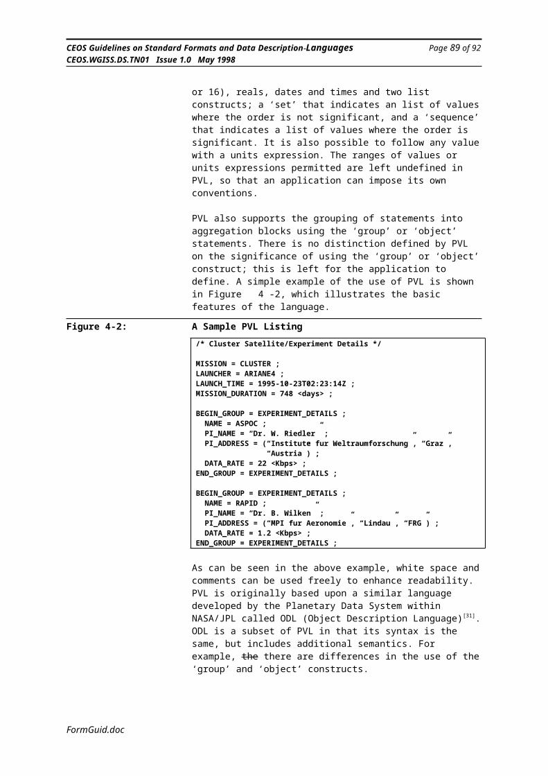
CEOS Guidelines on Standard Formats and Data Description Languages Page 91 of 92CEOS.WGISS.DS.TN01 Issue 1.0 May 1998
IDL Interactive Data LanguageIEEE Institute of Electrical and Electronic Engineers
IKI Institute of Space ResearchINPE Instituto Nacional de Pesquisas Espaciais
IPI Image Processing and InterchangeIPI-DF Image Processing and Interchange - Data FormatIPI-IIF Image Processing and Interchange - Image Interchange Facility
IPI-PIKS Image Processing and Interchange - Programmers Imaging Kernel SystemIRG Inter-Record Gap
ISAS Institute of Space and Astronautical ScienceISBN International Standard Book Number
ISLSCP International Satellite Land Surface Climatolgy ProjectISO International Standards Organisation
ISRO Indian Space Research OrganizationISTP International Solar Terrestrial PhysicsJPL Jet Propulsion Laboratory
KFKI Research Institute for Particle & Nuclear Physics
LGSOWG Landsat Ground Station Operators Working GroupLTWG Landsat Technical Working Group
LVO Label Value ObjectMADEL Modified ASN.1 as a DDL
MMBS Multi Mission Browse ServiceMMRA Multi-mission Reference Archive
MOC Ministry of CommunicationsMPH Main Product Header
NASA National Aeronautics and Space AdministrationNASDA National Space Development Agency of Japan
NCSA National Center for Supercomputing ApplicationsnetCDF Network Common Data Format
NIST National Institute of Standards and TechnologyNOST NASA Office of Standards and Technology
NSIDC National Snow and Ice Data CenterNSSDC National Space Science Data Center
ODL Object Description LanguageOOP Object Oriented Programming
PC Personal ComputerPVL Parameter Value LanguageRFC Released Request for CommentRGB Red-Green-BlueSAR Synthetic Aperture RadarSCSI Small Computer Systems InterfaceSDF Standard Data Format [an EOS acronym]
SDTS Spatial Data Transfer StandardSFDU Standard Formatted Data Unit
SPH Specific Product HeaderSRD Software Requirements Document
TCP/IP Transmission Control Protocol/Internet ProtocolTM Thematic mapper
TSDN Transfer Syntax Description NotationUSGS United Sates Geological Survey
UTC Universal Co-ordinated TimeWORM Write Once Read ManyWWW World Wide Web
XDR External Data Representation
FormGuid.doc
CEOS Guidelines on Standard Formats and Data Description Languages Page 92 of 92CEOS.WGISS.DS.TN01 Issue 1.0 May 1998
APPENDIX C. REVISION HISTORY
Version A Created from “Technical Note on Standard Formats, Data Description Languages and Media” (LUK.502.EC21317/TN003) and other contributary texts.
Version B Editorial corrections. NASA review comments inserted. Introduction revised (maintenance plan added etc). Section 6.2 Intermediate Data Structures moved to Section 2.3. Section 3.3.10 added on GeoTIFF (to be expanded). Section 3.5 added on Specific Formats (to be completed). New Chapter 6 inserted on Software Support (to be filled in). Section on Data Compression (to be filled in) added after Format Translation (now Chapter 7). Text on Format Translation inserted. Text inserted into Conclusions and Recommendations. Appendix C Revision History added.
Version C Further editorial correction after comments from NASA, CNES and BNSC. Reformetted (reduced page length) to be compatible with US Letter page size. Chapter 6 on Software Support removed as this is already covered in the earlier Chapters. GeoTIFF section revised and added to Tables. Data Compression section (formerly 7.2) removed as being not central to the theme of the document. Appendix C Revision History Updated.
Version 1.0 No changes in content over Version C.
------ ------
FormGuid.doc