GUIDELINES MANUAL FOR ARCTIC AND SUBARCTIC FLOODPLAINS · GUIDELINES MANUAL FOR ARCTIC AND ... FOR...
176
Ul Biological Services Program FWS/088-80/09 0 ,...... ,...... ,...... co _C') 1980 :::; T""" 0 l.C) l.C) ,...... GRAVEL REMOVAL GUIDELINES MANUAL FOR ARCTIC AND SUBARCTIC FLOODPLAINS Environment Research and Development Program DEVELOPMENT rAL PROTECTION AGENCY j Fish and Wildlife Service U.S. Department of the Interior
-
Upload
trinhkhanh -
Category
Documents
-
view
237 -
download
1
Transcript of GUIDELINES MANUAL FOR ARCTIC AND SUBARCTIC FLOODPLAINS · GUIDELINES MANUAL FOR ARCTIC AND ... FOR...

Ul
Biological Services Program
FWS/088-80/09
0 ,...... ,...... ,...... co
_C')
~ 1980
:::; T"""
~-0 0 l.C) l.C) ,......
~ GRAVEL REMOVAL GUIDELINES MANUAL
FOR ARCTIC AND SUBARCTIC FLOODPLAINS
Environment Research and Development Program ~CHAND DEVELOPMENT rAL PROTECTION AGENCY j
Fish and Wildlife Service
U.S. Department of the Interior

The Biological Services Program was established within the U.S. Fish and Wildlife Service to supply scientific information and methodologies on key environmental issues that impact fish and wildlife resources and their supporting ecosystems.
Projects have been initiated in the following areas: coal extraction and conversion; power plants; mineral development; water resource analysis, including stream alterations and western water allocation; coastal ecosystems and Outer Continental Shelf development; National Wetland Inventory; habitat classification and evaluation; inventory and data management systems; and information management.
The Biological Services Program consists of the Office of Biological Services in Washington, D.C., which is responsible for overall planning and management; National Teams, which provide the Program's central scientific and technical expertise and arrange for development of information and technology by contracting with States, universities, consulting firms, and others; Regional Teams, which provide local expertise and are an important link between the National Teams and the problems at the operating level; and staff at certain Fish and Wildlife Service research facilities, who conduct in-house research studies.
ARLIS Alaska Resources Library & Information Services
Library Building, Suite 111 3211 Providence Drive
Anchorage, AK 99508-4614

0 ,...._ ,...._ ,...._ (0 ('I)
T""
0 0 I!) I!) ,...._ ('I)
('I)
FWS/088-80/0a June 1980 Q.l
5¢0 .u~
,/10 I ?IJ/tJ9
GRAVEL REMOVAL GUIDELINES MANUAL FOR ARCTIC AND SUBARCTIC FLOODPLAINS
U.S. FISH AND WILDLIFE SERVICE
by
Woodward Clyde Consultants 4791 Business Park Blvd., Suite 1, Anchorage, Alaska 99503
Principal Authors
M.A. Joyce L.A. Rundquist L.L. Moulton
With Input From
R.W. Firth, Jr. E.H. Follmann
Contract Number FWS-14-16-0008-970
This study was funded in part by the
Interagency Energy-Environment Research and Development Program Office of Research and Development
U.S. Environmental Protection Agency
Performed for the Water Resources Analysis Project
Office of Biological Services U.S. Department of the Interior
Washington, DC 20240
en <!) u .E <!)
r/1 !: .s- ~ ~- -ro ..- llJ \.0 E llJ .~ '"1 t2·50~
rJ'J. ,E. r/1 <!) '8, ~ c(l oil g 0\
~ ;>,·= ..g ~ ~ a ::::l·;;: < ~ Js ·;; 2. "' ~ ·- co ~ OJ) """'-< ...l "" »- ...
IZl '""'..- 0
~~~--5 ::>·- !: 0 ...l < ~ ~ ~

DISCLAIMER
The opinions, findings, conclusions, or recommendations expressed in this report are those of the authors and qo not reflect the views of the Office of Biological Services, Fish and Wildlife Service or the Office of Research and Development, U.S. Environmental Protection Agency.

INTRODUCTION
A study was initiated in mid-1975 to evaluate the effects of gravel
removal from arctic and subarctic floodplains in Alaska. The primary purpose
of the project was to provide an information base to assist 'resource man
agers in formulating recommendations that would minimize detrimental environ
mental effects of gravel removal from floodplain material sites. To achieve
this objective 25 material sites were studied by a team of scientists and
engineers. Three major products resulted from the study. They are: (I l a
Technical Report presenting synthesis and evaluation of the data collected
at the sites, (2) a Guide I ines Manual that aids the user in developing plans
and operating material sites to minimize environmental effects, and !3) a
Data Base filed with the U. S. Fish and Wildlife Service in Anchorage con
taining raw and reduced data, aerial and ground photographs, and other
relevant material from each site. This report is the Guide I ines Manual.
APPLICABILITY OF THE GUIDELINES
It is important to recognize that the guide! ines contained in this
manual were developed from a study of 25 floodplain material sites in arctic
and subarctic Alaska. Therefore, they deal neither generally nor specifi
cally with material sites in upland or coastal situations. Similarly, they
do not include evaluation of the relative acceptabi I ity of uti I izing an
existing active or abandoned material site or an abandoned structure contain
ing gravel lsuch as a dri I I pad or airstrip! rather than a floodplain site.
This should not be interpreted as recommending sites in floodplains over
other locations. WHEN A NEED FOR GRAVEL HAS BEEN IDENTIFIED, ALL ALTERNA
TIVES SHOULD BE CONSIDERED. ONLY AFTER A FLOODPLAIN HAS BEEN SELECTED FOR
THE PROPOSED MATERIAL SITE DO THE GUIDELINES CONTAINED HEREIN BECOME APPLI-
CABLE. However, if used cautiously some guide I ines may be uti I ized in other
site and regional situations.
The 25 material sites exhibited a range of variation in site age,
gravel mining method and location; and river configuration, origin, and
size. Selected sites were minimally affected by complicating factors such as

nearby bridges, culverts, vi II ages, and other material sites. The latter
case is significant in the application of these guide I ines. On large proj
ects it is sometimes necessary to locate a series of material sites in close
proximity along the floodplain of a river. The effects of multiple material
sites in a floodplain were not evaluated in this study. Hence the appl i
cation of these guidelines to multiple site projects must recognize this
shortcoming.
The user should be thoroughly fami I iar with the contents of the Techni
cal Report to give perspective to the guide I ines for their effective use.
THE GUIDELINES ARE DESIGNED TO DIRECT THE PROCESS OF IDENTIFYING, PLANNING,
PREPARING, OPERATING, AND CLOSING MATERIAL SITES; THEY ARE NOT MEANT TO BE
USED AS STIPULATIONS TO BE USED IN EACH AND EVERY CASE.
It is essential that the user of these guide I ines consider each materi
al site individually. Identification of unique characteristics may require
that certain guidelines be ignored or interpreted differently, or different
combinations of guide I ines be considered. This manual is intended for use by
all individuals interested in floodplain gravel removal.
GRAVEL REMOVAL METHODS AND CLASSIFICATION
A variety of gravel removal methods and river characteristics are
covered by this manual. In general, these methods and river characteristics
consist of:
I. Scraping exposed or vegetated gravel from active and inactive flood
plain and terrace deposits. Scraping usually does not involve work
ing in active channels.
2. Pit excavation of vegetated gravel deposits located in inactive
floodplains and terraces.
3. Dredging from the bed of active channels of large and medium-sized
rivers.
2
SUMMARY OF PROJECT RESULTS AND CONCLUSIONS
Study of 25 floodplain material sites has shown that disturbance result
ing from gravel removal operations can be minimized. Two gravel mining tech
niques were used at the study sites, scraping of surface or near-surface
deposits and pit excavation of deep deposits.
In general, approaches to minimize environmental changes caused by
scraping included maintaining buffers between active channels and the work
area and avoiding:
• I nstream work
• Mining to depths and in locations that induce permanent channel
shifts or ponding of water
• Clearing of riparian vegetation
• Disturbance to natural banks
Large rivers and braided rivers generally provide the most accessible
gravels for scraping. Gravel mining using scraping technqiues in these areas
frequently resulted in the least environmental changes.
Pit excavations resulted in permanent loss of terrestrial riparian habi
tat, however, many pits increased local habitat diversity. These newly
created habitats frequently received concentrated uti I ization by local
fauna, particularly fish, waterfowl, shorebirds, and furbearers. Large
quantities of material were excavated using pit mining techniques. Pits that
were located on the inactive side of the floodplain, and were separated by
vegetated buffers in the range of 50 to 100m, generally did not influence
active channel hydraulics.
Pits were found to be most beneficial to local fauna when they exhib
ited the following characteristics:
3
• 2 ha or more in size
• Contained diverse shore I ine configuration
• Contained diverse water depths
• Contained islands
• Contained an outlet connected to active channels
4

PROCEDURES FOR GUIDELINE USE
To use this manual it is necessary to acquire information on site loca
tion, operation, and environmental conditions. The information consists of
descriptions of the site and gravel removal methods that wi II allow predic
tion of floodplain changes.
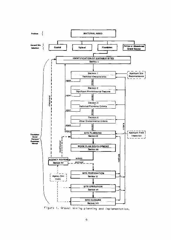
The manual is divided into seven sections based primarily on the order in
which a site wi I I be selected, reviewed, and worked !Figure I I. Although site
selection is the primary topic of Section I, much of the information in the
other sections is also valuable in selecting appropriate mining locations
and methods. For this reason, the entire manual should be read and clearly
understood before deciding on a final work plan. For ~xample, much of the
information in Section VI; SITE OPERATION can be valuable in determining
where selection of a specific method or location may increase the amount of
avai I able material while decreasing environmental alteration.
After the guide! ines have been thoroughly reviewed, it is recommended the
sequence presented below should be followed.
SITE APPLICANT
I. Identify suitable sites using the procedures described in Section I.
2. Develop a tentative plan on how and where to remove the required
gravel within the proposed site. Acquire field data needed to complete
Site Planning as described in Section II.
3. Evaluate the proposed plan by applying the appropriate guide I ines from
the SITE PREPARATION, SITE OPERATION, and SITE CLOSURE Sections. This
may identify alternative methods or locations and potential problems,
speed the review process, and lead to more efficient site operation.
4. Develop a formal Work Plan, as described in Section I I I, to be sub
mitted to the appropriate agency.
5
Problem
Generll Sit• Selection
Fk:Jodplain c;. ....
Remowll Guidelinn ........
II I I I I I I I I I I
.,.I
e 1 0. 0. :J! 'C
I
~-
cl g I .111 ]I E I
I
~- ~e;;cy-Si~ i I Visits I I I ---,---
1
MATERIAL NEED
IDENTIFICATION OF SUITABLE SITES
Section I
WORK PLAN DEVELOPMENT Section Ill
submit
_ .,!P.£!0.!!:11 ___ 1 I
SITE PREPARATION
SectionV
1 ____ -f-----'S~I~T=E~O~P=E'-'R!"A':'T._,IO"-'N'------I Section VI
: _____ ...1·----~S~IT~E:..:C~L~O,s..,u.,R._,E,__ __ _ Section VII
Figure I. Gravel mining planning and implementation.
6
5. Work and close the site in accordance with the appropriate guide I ines
and approved Work Plan.
SITE REVIEWER
I. After receiving a work plan completed in accordance with Sections
I through I I I, evaluate the plan and site location for the presence of
significant environmental features identified in Section IV.
2. Visit the site to evaluate the technical feasibi I ity, proposed bounda
ries, habitat quality, and possible environmental concerns.
3. Use Sections V through VII to evaluate the Work Plan and suggest
modifications, if appropriate.
4. Following approval, conduct site visits during operation and closure
to check adherence to the approved Work Plan.
7
saunap1ne> IBAowa~::~ laAeJe>


Identification of Suitable Sites Section I
Page
GENERAL GUIDELINES . II
SPECIFIC GUIDELINES II
Technical Characteristics of Alternative Sites . . . . • . . . . 12
Areas or Species of Special Concern . . . • . . • . . . . • . . 12
Technical and Economic Criteria .• 13
Other Environmental Criteria • . . 14
VERIFICATION OF SITE ACCEPTABILITY • . . I~
Identification of Suitable Sites Section I
A. GENERAL GUIDELINES
A number of factors influence the suitabi I ity of a gravel removal site.
Among these are:
• Technical Requirements- such as quantity and quality of avai I able
material, required processing )washing of fines I
• Economics- such as hauling distance, and site preparation and
rehabi I itation requirements (overburden removal, river-training
structures, and site grading)
• Environmental Characteristics- including location within jhe f load
plain, and biological characteristics of the site
Many projects require more than one type of material, and these types
often wi I I not be avai I able from a single material site. Linear projects
such as pipe I ines and roads wi I I require sites spaced along their
length. In regions where winter construction activities are required,
stockpi I ing of gravel in summer may be necessary to provide material
with lower moisture content.
B. SPECIFIC GUIDELINES
Because of the need to incorporate technical, economic, and environ
mental factors, siting decisions must be considered on a case-by-case
basis. However, a sequence of four levels of decisions should be uti 1-
ized in site selection. AI I levels should consider both previously undis
turbed sites as wei I as previously mined sites. There may be occasions
I. IDENTIFICATION OF SUITABLE SITES

when previously mined sites are more suitable because of the presence of
access roads, airstrips, removed overburden, and existing unused stock
pi led material.
A pre I iminary site visit is appropriate to provide input to the follow
ing decisions.
I. Decision I -Technical Characteristics of Alternative Sites
Two initial steps are important in the site identification process.
a. Determine that the area can provide material meeting the
technical and volumetric requirements of the project. These
requirements must be obtainable within suitable buffers !refer
to buffer recommendations in Section VA 3 and Appendix AI.
b. Determine if more than one specific site that meets these
requirements exists in the area
Failure to determine avai labi I ity of suitable material can result
in unnecessary economic cost and environmental damage if initial
mining activities show a site to be unsuitable. It is desirable to
identify alternative sites in an area of interest because not alI
sites wi I I be acceptable.
2. Decision 2 -Areas or Species of Special Concern
The alternative sites identified in Decision I should be evaluated
relative to their disturbance of the features I isted below. A site
affecting these areas should be modified, or in some cases dis
carded, to minimize or eliminate any effect.
a. Threatened or endangered species and their habitats that are
deemed essential to the survival or recovery of these species
that are recognized by Federal and State governments. A cur
rent I isting of species and information as to their distri-
12 I. IDENTIFICATION OF SUITABLE SITES

but ion may be obtained from the U. S. Fish and Wildlife
Service or the State Fish and Game agency. Sites affecting
these species or their habitats may be prohibited, or require
substantial justification.
b. Habitats I imiting local populations !such as fish spawning and
overwintering habitats, Dal I sheep lambing areas or raptor
nesting habitats!. Sites directly affecting these habitats
should not be considered further unless alternate sites are
not avai !able.
c. Undercut vegetated banks and associated riparian zones
d. Incised vegetated banks and associated riparian zones, except
for proper I y uti I i zed access by f i I I ramps
e. Springs
f. Active channels in smal I rivers of meandering, sinuous, and
straight configurations
g. Wetlands- The primary criteria most frequently used in wet
land definitions include presence of water-saturated soi I con
ditions, and vegetative communities adapted to such con
ditions. For current definition, delineation and jurisdiction
refer to local offices of the U. S. Army Corps of Engineers.
h. Other Federal, State, and pr1vate lands with special use and
regulation such as wilderness areas, parks, wildlife refuges,
archaeological areas, and historical landmarks
3. Decision 3 - Technical and Economic Criteria
Following the determination that suitable material can be obtained
from one or more sites without disturbance to areas or species
13
I. IDENTIFICATION OF SUITABLE SITES
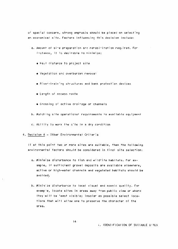
of special concern, strong emphasis should be placed on selecting
an economical site. Factors influencing this decision include:
a. Amount of site preparation and rehabi I itation required. For
instance, it is desirable to minimize:
• Haul distance to project site
• Vegetation and overburden removal
• River-training structures and bank protection devices
• Length of access route
• Crossing of active drainage or channels
b. Matching site operational requireme~ts to avai !able equipment
c. Abi I ity to work the site in a dry condition
4. Decision 4- Other Environmental Criteria
If at this point two or more sites are suitable, then the following
environmental factors should be considered in final site selection:
a. Minimize disturbance to fish and wildlife habitats. For ex
ample, if sufficient gravel deposits are avai fable elsewhere,
active or high-water channels and vegetated habitats should be
avoided.
b. Minimize disturbance to local visual and scenic quality. For
example, locate sites in areas away from pub! ic view or where
they wi II be least visible; insofar as possible select loca
tions that wi I I a! low one to preserve the character of the
area.
14 I. IDENTIFICATION OF SUITABLE SITES

c. Bed load replenishment rate should be considered in site selec
tion if the I ife span of the site is to cover several consec
utive years, even if there wi II be inactive periods. Glacial
and mountain origin rivers, particularly near headwaters, have
potential ty higher replenishment rates than rivers originating
in foothi Its or coastal plains.
d. Projects requiring large gravel quantities !roughly 50,000 m3
or morel, should consider the following:
• Scraping of unvegetated, mid-channel bars and lateral bars
in braided rivers, and medium and large split channel
rivers. This recommendation should be followed as long as
suitable buffers lsee Section V A 3 and Appendix Al can be
maintained.
• Pit excavation in terraces or inactive floodplains, as long
as sufficient buffer is maintained between the pit and the
active floodplain
e. Projects requiring less than 50,000 m3 should consider:
• Scraping unvegetated mid-channel and lateral bars in braided
rivers and large and medium split channel rivers; this recom
mendation should be followed as long as suitable buffers can
be maintained
• Scraping point bars of large and medium meandering rivers
• Scraping in terraces or inactive floodplains
C. VERIFICATION OF SITE ACCEPTABILITY
Before proceeding with SITE PLANNING, review the selected site on the
basis of the entire Guide! ines Manual. Give special attention to the
15 I. IDENTIFICATION OF SUITABLE SITES

SITE PREPARATION and SITE OPERATION sections. The matrix tables within
SITE OPERATION specifically present recommendations about gravel deposit
type and location, and mining method.
The purpose of this verification review is to minimize decision-making
delays resulting from failure to consider site specific features.
16 I. IDENTIFICATION OF SUITABLE SITES
81
S3Nil30in9 JI~IJ3dS
· S3Nil30in9 lV~3N39
II uon~as 6U!UUeld 9I!S

Site Planning Section II
Site planning should incorporate the SITE PREPARATION, SITE OPERATION,
and SITE CLOSURE guide! ines presented in Sections V, VI, and VII.
A. GENERAL GUIDELINES
I. If the technical method of gravel removal has not been determined
during site selection, then either scraping, pit excavation, dredg
ing or a combination can be chosen by reviewing the SITE OPERATION
guide! ines
2. Design of the specific work area boundaries should incorporate
the fat lowing factors:
a. Site configurations should avoid use of long straight I ines
and be shaped to blend with physical features and surroundings
!Figure 2l:
• Scraping point bars of meandering and sinuous systems to
maintain slopes and contours resembling those of the natural
bars
• Scraping mid-channel and lateral bars of braided systems,
to maintain natural gravel bar shapes
• Excavating pits to provide irregular shore! ines with curved
configurations, islands, spits, and diverse shore! ine depths
b. Vegetated areas should not be disturbed when sufficient quanti
ties of gravel can be obtained within prescribed buffers in
unvegetated areas of floodplains !buffers guide! ines are in
Section VA 3 and Appendix Al
I I. SITE PLANNING 18
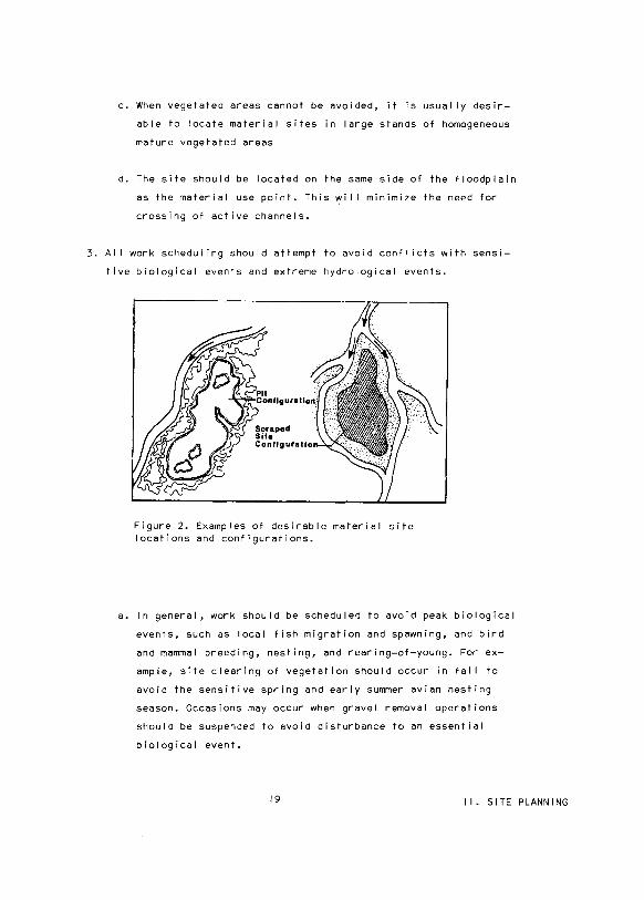
c. When vegetated areas cannot be avoided, it is usually desir
able to locate material sites in large stands of homogeneous
mature vegetated areas
d. The site should be located on the same side of the floodplain
as the material use point. This wi II minimize the need for
crossing of active channels.
3. AI I work scheduling should attempt to avoid conflicts with sensi
tive biological events and extreme hydrological events.
Figure 2. Examples of desirable material site locations and configurations.
a. In general, work should be scheduled to avoid peak biological
events, such as local fish migration and spawning, and bird
and mammal breeding, nesting, and rearing-of-young. For ex
ample, site clearing of vegetation should occur in fal I to
avoid the sensitive spring and early summer avian nesting
season. Occasions may occur when gravel removal operations
should be suspended to avoid disturbance to an essential
biological event.
19 I I. SITE PLANNING
b. Where site work is occurring in the active or inactive flood
plain, scheduling should allow for work suspension and removal
of equipment, materials, and stockpiles from the floodplain
during spring breakup or other predictable flood events
4. After incorporating the conclusions from the four levels of deci
sions from Section I into a final site selection, a site investi
gation (described in Appendix Bl should be conducted to:
a. Verify that the candidate site can produce the quantity and
quality of desired gravel
b. Collect hydraulic measurements such as discharge, channel
cross sections, and bed material size distribution whenever
possible to assess the hydraulic conditions of the natural
channel (see Appendix Bl.
c. Determine the presence or absence of I imiting fish and wild-
1 ife habitat within the project site. Analysis should be based
on annual biological requirements I i.e., fish spawning and
overwintering habitat!.
d. Flag site boundaries and buffer locations in preparation for
an agency site inspection. Flagging should be highly visible,
of weather resistant material, and maintained through site
operation and closure.
• Mark site boundaries on mature trees in timbered areas with
some highly visible material (such as paint or cloth
material l.
• For flagging in the open-water season use 1-m metal stakes
or rods driven approximately 0.5 m into the ground with
a red flag of approximately 15 x 15 em attached
20
I I. SITE PLANNING

• At sites to be opened during winter, alI work area locations
lsuch as active channels, buffer locations, vegetated areas,
and gravel deposits) should be surveyed from reference points
established during the initial open-water site visit !Figure
31. Reference points should be selected so they can be found
in heavy snow cover during future site preparation. Establish
ment of these surveys wi I I reduce accidental damage to active
channels and buffer zones.
Three or more temporary bench marks which can be located during winter
Do a summer trave or stadia survey to locate material site boundaries
~:
Figure 3. Schematic diagram showing recommended survey at sites w~ich are to be opened during winter.
5. If winter active-channel mining is contemplated, an additional site
visit should be conducted during winter. This visit is to determine
the presence of water at or downstream from the proposed site.
21 I I. SITE PLANNING

B. SPECIFIC GUIDELINES
Specific site planning should proceed based upon the selected gravel
removal method.
I. Scraping in Active and Inactive Floodplains:
a. Material sites should be mined to ensure that after the rna-
terial is removed, sufficient gravel remains to maintain the
low-flow channel configuration (refer to Section VI B 2)
b. Since it is most efficient to work scraped sites in a dry
condition, the average depth of the groundwater table during
the desired period of mining and the effective use of river
training structures should be assessed !refer to Appendix C on
river-training structures)
2. Pit Excavation in Inactive Floodplains and Terraces:
a. Pits should be considered when a large amount of gravel
!>50,000 m3 ) is required from a river that does not have large
exposed gravel deposits. If scraping is conducted in a situ
ation where more gravel is required than is accessible within
the guide I ines for scraping, overmining may result with corres
ponding habitat and channel alterations. In these cases, it is
preferable to go to inactive floodplains or terraces and exca
vate a deep pit !refer to Appendix Don pit design).
b. Pits should be located in areas where they wi II have a low
probabi I ity of diverting channels into the mined area. This
means they should be located on terraces, inactive floodplains,
or stable islands with the recommended buffer. Terraces are
preferred because of the reduced probabi I ity of channel diver
sion.
22 I I. SITE PLANNING

c. It is usually desirable to locate the pit within a dominant,
homogeneous mature vegetative community. This location wi I I
reduce the chance that a terrestrial habitat of I imited avail
ability will be affected and will generally increase habitat
diversity.
d. It should be decided during site planning whether or not the
pit is to be connected to the river following the mining opera
tion
• A pit outlet provides an avenue of escape for fish that
become trapped in the pit during high water. A connected
pit, if properly designed, can provide fish rearing and
overwintering and increase the avai labi I ity of sport fish.
Conditions necessary to provide suitable fish habitat in
clude a diversity of depths with an average depth that mini
mizes the probabi I ity of winter mortality.
• An unconnected pit has the potential to trap fish during
high water. If the pit is adequately protected from flooding
with a buffer of suitable height, and if the pit is not to
be managed for fish the creation of overwintering habitat is
not necessary and the average depth is not critical. A diver
sity of water depths is desirable to create adequate water
fowl and shorebird habitat.
3. Dredging in Active Channels of Large and Medium Rivers
a. Dredging in active channels of large and medium rivers should
be considered only if suitable floodplain sites are unavai 1-
able outside the active channel. In this situation, nonflood
plain sources also should be evaluated.
b. Sites located in active channels should consider the following:
23
I I. SITE PLANNING

i I Essential aquatic habitat in and downstream from the
site
iiI Unimpeded instream migrations
iii I Maintenance of natural pool :riffle ratio; riffles should
be avoided except in the following situations:
• In a long riffle, excavation may be acceptable near
the middle of the riffle
• When more rapid site recovery is desirable
• When the riffle is unproductive aquatic habitat be
cause of cementation or infiltration by fine"sediments
• Where deepening the thalweg may reduce or eliminate
aufeis development
24
I I. SITE PLANNING

Work Plan Development Section Ill
Page
Maps, Sketches, Photographs 26
Legal Description 26
Site Description 27
Environmental Description 28

Work Plan Development Section Ill
Detailed work plans should be prepared and submitted as part of the appl ica
tion to the appropriate review agency. Work plans should include detailed
sketches, ground photographs, topographic maps, and if avai I able, aerial
photographs showing:
• Accurate site boundaries
• Individual sequential work areas and boundaries
• Buffer locations and boundaries for both individual work areas and
the total site
• Locations of alI floodplain temporary and permanent structures planned
for site operation and closure !e.g., access roads, river-training struc
tures, bank protection devices, stockpiles, washing and processing struc
tures, and overburden pi lesl
• Locations of gravel-use points !such as access roads, airstrips, and
camp padsl
Visual resource classification maps, if avai I able from State or Federal agen
cies, of the region surrounding the work site, should also be submitted. Spe
cific sections of the work plan should present written descriptions that
address the following topics.
A. A brief legal project description identifying:
I. Names and addresses of applicant and major contractors, if known
26 I I I . WORK PLAN DEVELOPMENT
2. Intended material use, location of material use, and anticipated
I ife of the project uti I izing the material
3. Life of the material site
4. Ownership of material site and adjacent lands
B. A technical site description identifying:
I. Size and specific location of all individual and cumulative work
areas
2. Season, duration, and frequency of all site work by individual work
area
3. Buffer locations, dimensions, type of vegetation, and soi I
description
4. Methods, schedules, and locations for vegetative and overburden
clearing, temporary storage and hand I ing, and permanent disposal
5. Quantity, type, and use of material to be removed from each work
area
6. Method of gravel removal· in each work area, including type and
number of equipment and identification of each material handling
step to be performed within the material site I i.e., collection,
stockpi I ing, sorting, washing, processing, transporting!. Locations
and operation of each hand I ing step should also be identified.
Washing operation descriptions should identify si It control proce
dures and processing operations should identify use and storage
locations of materials such as solid waste and cement-processing
additives.
7. Cross-sectional configuration and location of progressive working
elevations by season or major project scheduling periods. For
I I I . WORK PLAN DEVELOPMENT 27

example, if the site is to be worked over several years, the de
signed profile and configuration during each spring breakup and low
summer flow should be identified. Final working profile and config
uration and site closure profile and configuration should also be
identified.
8. Specific locations, specifications, material composition, and con
struction method of access roads, river-training structures, and
si It control structures.
9. Site closure lrehabi I itationl methods and procedures including loca
tions and specifications of permanent structures lsuch as overburden
pi lesl. At pit sites consideration should be given to whether access
should remain after site closure. This decision influences the
design I ife of the access road.
10. Descriptions of logistical support and material transportation
methods, general routes, and frequency to and from the material site
C. An environmental description of the project area identifying:
I. Known biological resources of the general vicinity, including fish
ery resources of the subject river system
2. Timing of major fish and wildlife history events and presence of
I imiting habitat occurring in the vicinity of the material site
3. Hydraulic characteristics I such as channel configuration and dis
charges) in the vicinity of the material site
D. The approved work plan should be considered an integral part of the
project by both the permittee and the permitting and monitoring agencies
28 I I I. WORK PLAN DEVELOPMENT

Agency Review Section IV
Disapproval Basis .•.
First Field Inspection
Second Field Inspection
Third Field Inspection
Page
30
31
31
32

Agency Review Section IV
A. The proposed material site location and accompanying work plan should
be reviewed by appropriate agencies to evaluate the compatibi I ity of the
project with the environment. This review should consider disapproval
or modification of the work plan if the material site directly affects
areas or species of special concern. Examples of such areas or species
include:
I. Threatened or endangered species and their habitats that are deemed
essential to the survival or recovery of these species that are
recognized by Federal and State governments. A current I isting of
species and information as to their distribution may be obtained
from the U.S. Fish and Wildlife Service or the State Fish and Game
agency. Sites affecting these species or their habitats may be
prohibited, or require substantial justification.
2. Habitats I imiting local populations I such as fish spawning and
overwintering habitats, Dal I sheep lambing areas or raptor nesting
habitats!. Sites directly affecting these habitats should not be
considered further unless alternate sites are not avai I able.
3. Undercut vegetated banks and associated riparian zones
4. Incised vegetated banks and associated riparian zones, except for
proper I y uti I i zed access by f iII ramps
5. Springs
30 IV. AGENCY REVIEW

6. Active channels in sma II rivers of meandering, sinuous, and straight
configurations
7. Wetlands- The primary criteria most frequently used in wetland
definitions include presence of water-saturated soi I conditions, and
vegetative communities adapted to such conditions. For current
definition, delineation and jurisdiction refer to local offices of
the U.S. Army Corps of Engineers.
8. Other Federal, State, and private lands with special use and regula
tion such as wilderness areas, parks, wildlife refuges, archaeolog
ical areas, and historical landmarks
B. A field inspection of the proposed site by the appropriate agency should
take place prior to site approval. A field inspection as described in
Appendix B should occur during an open-water season and include an evalu
ation of:
I. Overall technical feasibility of project as detailed in the work
plan
2. Overall quality of fish and wildlife habitat to be disturbed
3. Presence of any previously unknown features identified in Section
IV-A
4. Hydraulic characteristics such as discharge and stage in the vicin
ity of the material site
Alternative sites should be requested of the applicant if it is judged in
this review that the material site wi I I alter areas or species of special
concern to the point that population survival is affected.
C. A second inspection by the appropriate agency should occur during site
operation to:
31 IV. AGENCY REVIEW

I. Confirm that the work plan is being followed
2. Determine if unexpected biological, hydraulic,. or engineering char
acteristics warrant a deviation from the original work plan
D. A third field inspection by the appropriate agency should occur in the
latter stages of site closure prior to site abandonment and removal of
essential site closure equipment to ensure:
I. Final slopes, contours, and configurations of the work area comply
with the intent of the work plan
2. All additional site closure work has been performed and the site
will be abandoned, within practical limits, as close to original
conditions as possible
Additional visits after closure may be appropriate I i.e., to monitor erosion
centro I I.
32 IV. AGENCY REVIEW

Site Preparation Section V
Page
GENERAL GUIDELINES ••......... 34
Verify Boundaries . . . . • . . . . 34
Access . . . . • • . • . . . . . . 34
Buffers • • . • • . . . . . . . . . 35
Dikes . . . • • . . • . . . . • . . 40
Vegetation Clearing .......• 42
Vegetation/Overburden Hand I ing .. 42
Settling Ponds 44
SPECIFIC GUIDELINES FOR SCRAPED SITES •• 44

A. GENERAL GUIDELINES
Site Preparation SectionV
I. At sites opened during winter alI work area boundaries estebl ished
during the initial site visit !such as active channels, buffer loca
tions, vegetefed areas, gravel deposits) should be verified to avoid
accidental damage to active channels, buffer zones, and vegetated
banks
2. Design of floodplain access should incorporate the following factors:
e. Minimize access through vegetated habitats
b. If necessary to traverse vegetated areas:
• During winter do not remove the organic layer end do not
cover the access route with gravel; use ice roads to avoid
compaction of organic layers
• During summer do not remove the organic layer, but protect
from mechanical ripping and tearing by covering with gravel
c. Floodplain access should occur at the inside of e meander to
avoid trefficing incised banks at outside meanders
d. Avoid crossing other incised floodplain banks
e. When a bank crossing is required it should be protected with
a gravel fl I I ramp
f. Avoid crossing active channels
34 V. SITE PREPARATION
g. When required, active channels should be crossed via temporary
bridges, low-water crossings, or properly culverted access road.
Refer to Appendix Eon fish passage.
h. Floodplain travel to and from the work area should occur only
on designated access roads
3. Buffers are areas of undisturbed ground surface that are designed~
maintain the integrity of active channels. In general, low-flow or
flood-flow buffers are recommended at a site. Low-flow buffers are
recommended for scraping operations on unvegetated gravel bars adja
cent to active channels. Flood -flow buffers should be used for scrap
ing or pit-mining operations that are separated from active channels.
Operators of gravel removal activities may desire to use buffers wider
or higher than those recommended in order to protect the site from
inundation while it is being worked, since water levels at the time of
mining may exceed those for which the buffer is designed.
a. The low-flow buffer is a strip of undisturbed ground surface
extending up the bank and beneath the water surface from the low
summer flow water's edge !Figure 41. Its purposes are:
• To maintain the integrity of the channel configuration and
• To minimize change to the aquatic habitat
The boundaries of the low-flow buffer are defined as follows
!Figure 51:
i I The upper I imit at any location along the channel is that
point on the bank that is the lesser of the following:
• having an elevation that is 0.5 m above the low summer
flow water surface elevation
35 V. SITE PREPARATION

Figure 4. Schematic diagram of the low-flow buffer.
w
---~h~E~~-~~~~~~~-------~-o.sm }sm
'4.ow- Flow Buffer
o.sw
Figure 5. Schematic diagram showing low-flow buffer boundaries.
36

• having a horizontal distance to the low summer flow
water's edge which is equal to one-half the channel
top width at channel-ful I flow conditions
i il The lower I imit at any location along the channel is that
point on the bed that has a horizontal distance to the
water's edge which is 10 percent of the top width of the
low summer flow channel.
b. The flood-flow buffer is a zone of usually undisturbed flood
plain, often vegetated, separating the material site from the
active channel !sl !Figure 6). lts purpose is to prevent the
Figure 6. Schematic diagram of the f load-flow buffer.
37 V. SITE PREPARATION
active channel lsi f~om dive~ting th~ough the mate~ial site fo~
a selected pe~iod of time. Although it is p~efe~able to use
natu~al vegetated buffe~s, man-made buffe~s in the fo~m of ~ive~
t~aining st~uctu~es and bank p~otection devices lsee Appendix Cl
may be necessa~y whe~e natu~al buffe~s do not exist o~ a~e too
low to be effective.
i I Flood-flow buffe~ design, as discussed in Appendix A,
should include conside~ation of:
• Buffe~ location with ~espect to the active channel lsi
and the mate~ial site
• Buffe~ width sufficient to withstand anticipated
e~osion without jeopa~dizing the integ~ity of the
buffe~
• Buffe~ height sufficient to dive~t floods
iiI lmpo~tant va~iables to the selection of buffe~ location,
width, and height include:
• Channel configu~ation
• Rive~ size
• Hyd~ology
• Active channel alignment
• Channel aufeis
• Pe~maf~ost o~ ice-~ich banks
• Type of vegetation
38 V. SITE PREPARATION
• Soi I composition
iii I Recommended flood-flow buffer designs are I isted below
for scrape and pit gravel removal operations:
• Scrape- In these sites, it is recommended that the
site be protected from channel diversion by a buffer
for at least 5 to 8 years. This allows the vegetation
to become re-established. The following Table I ists
recommended minimum buffer widths for different river
sizes:
River size
Sma II
Medium
Large
Minimum width
lml
15
35
50
- The width can be reduced to half the recommended
minimum at the downstream end of the scraped site
-The height of the buffer should be at least as
high as the water level during a 5-year flood
• ~- In these sites, it is recommended that the
site be protected from channel diversion by a flood
flow buffer for a period of at least 20 years. This
provides a more long-term protection of the newly
created habitat. The following Table I ists recommended
minimum widths for different river sizes:
Minimum width
River size lml
Sma II 75
Medium 150
Large 250
39
V. SITE PREPARATION

- The width can be reduced to 20 percent of the
recommended minimum at the downstream end of the
pit
-The height of the buffer should be at least as
high as the water level during a 20-year flood
ivl Flood-flow buffers should be designed on a site-specific
basis following the guide I ines presented in Appendix A
under any of the following conditions:
• The material site is on a very large river le.g.,
Yukon River, Kuskokwim River, Tanana River, and
Col vi I le River)
• The avai fable space does not allow for a buffer of
recommended width
• Buffer height is lower than the recommended design
height
• The active channel is angled into the bank at an angle
greater than about 30 degrees
• Channel aufeis occurs in the river adjacent to the
site
• Banks consist of primarily sands, are sparsely vege
tated, or are ice-rich permafrost material
• Evidence of active bank erosion is found during the
site visit
4. Temporary dikes should be constructed around the site if the site
wi I I be inundated during operation !Figure 71. Refer to Appendix
C discussing river-training structures.
40 V. SITE PREPARATION
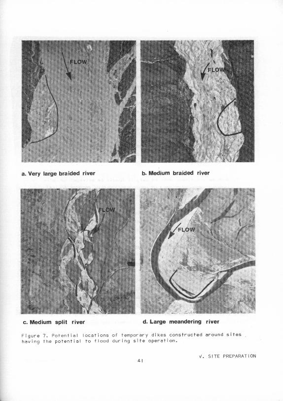
a. Very large braided river b. Medium braided river
c. Medium split river d. Large meandering river
Figure 7. Potential locations of temporary dikes cons t ructed around sites having the potential to flood during site operation .
v. SITE PREPARATION 41
a. These structures should be constructed to minimize disturbance
to low-flow channels
b. Dikes should be constructed of on-site gravel materials
c. Fish entrapment should be avoided at alI times
5. In cases where vegetated areas cannot be avoided, clearing should
proceed using the following guide I ines:
a. If possible, sites co~taining dense vegetative cover should
be cleared during periods that do not coincide with periods
of bird and mammal breeding, nesting, and rearing-of-young.
In most cases fal I would be the most desirable period for vege
tation removal.
b. When mature timber must be cut, it should be salvaged for pri
vate or commercial use. If no such use exists, timber should
be either:
• Stockpiled out of the active floodplain
• Used in site rehabi I itation of adjacent material sites
• Hauled to designated disposal areas
• Pi led and burned in accordance with appropriate regulations
6. Other vegetation and organic overburden can be mechanically cleared
and should be collected. This material should be saved for possible
use during site closure. At sites located in inactive floodplains
or terraces, this material should be broadcast over the surface during
site closure. In sites located only in an active floodplain, this
material can be pi led I not broadcast) within the site according to the
following recommendations. The presence of this material in the materi-
42 V. SITE PREPARATION

al site in an acceptable manner wi I I faci I itate more rapid vegetative
recovery and subsequent fauna recovery.
a. If the site occurs only within an inactive floodplain or terrace
in any configuration or size river, the material should be tempo
rarily stored either:
• In piles within or on the edge of the material site
• In a temporary storage area outside the material site !such
as an approved disposal area, material site, or unvegetated
inactive floodplain!
b. If the site occurs only within an active floodplain, vegetative
~lash and organic overburden should be disposed of based upon
river configuration:
i I If located in a braided river this material should not
be pi led or broadcast in the active floodplain of these
systems
i il If located in a meandering, sinuous, split, or straight
river this material can be handled as follows:
• If sufficient space exists away from the active chan
nel, store this material in piles within the material
site. On-site storage should occur at a location
that reduces repeated hand I ing. During storage the
material can be stockpiled in as smal I an area as
possible to reduce excessive site enlargement to
compensate for covered gravel. These materials should
be stockpiled in a location and in such a manner
that slope failures and erosion would not endanger
the adjacent stream or have other adverse effects.
These piles should be:
43 V. SITE PREPARATION
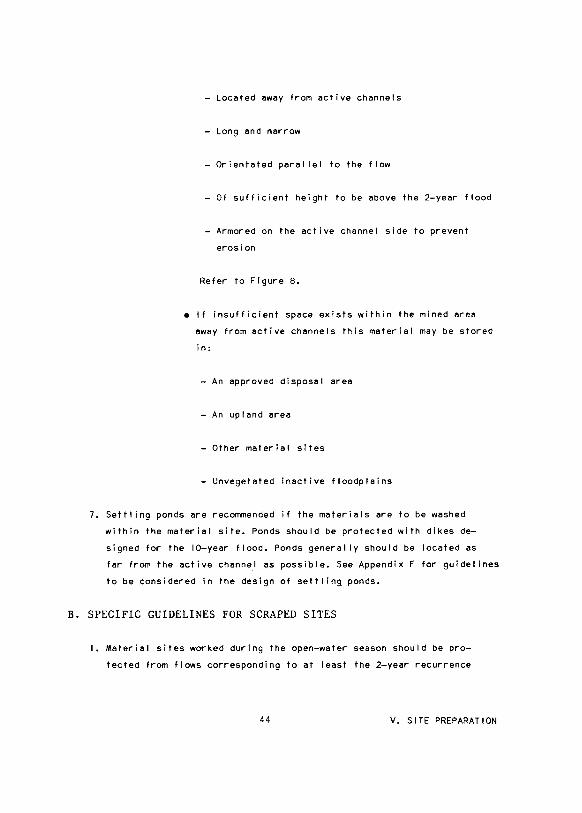
-Located away from active channels
- Long and narrow
-Orientated para I lei to the flow
-Of sufficient height to be above the 2-year flood
-Armored on the active channel side to prevent
erosion
Refer to Figure 8.
• If insufficient space exists within the mined area
away from active channels this material may be stored
in:
- An approved disposal area
-An upland area
-Other material sites
- Unvegetated inactive floodplains
7. Settling ponds are recommended if the materials are to be washed
within the material site. Ponds should be protected with dikes de
signed for the 10-year flood. Ponds generally should be located as
far from the active channel as possible. See Appendix F for guide! ines
to be considered in the design of settling ponds.
B. SPECIFIC GUIDELINES FOR SCRAPED SITES
I. Material sites worked during the open-water season should be pro
tected from flows corresponding to at least the 2-year recurrence
44 V. SITE PREPARATION

five Channel Terrace
~ ' II Temporary Storage of Overburden
'\ /J MinedSite Boundary
Channel
Figure B. Typical view of temporary storage of overburden showing desirable location, shape, and armor protection.
interval flood by dikes designed to withstand such floods without
erosion. These dikes should not encroach on the low-flow buffer. The
purpose of the dikes is to reduce the probabi I ity that flow wi I I pass
through the active site, thus reducing the potential for introducing
high concentrations of fine sediments into flows that are incapable of
transporting them to normal dispositional areas.
45 V. SITE PREPARATION

2. If an unvegetated site is armored by coarse gravels or cobbles that
do not meet project material specifications, they should be stock
pi led, used in a dike, or otherwise saved for dispersal over the
site during site closure.
3. If it is necessary to locate a material site in an active side chan
nel, it should first be diked off at the upstream and downstream
ends. The dikes should be constructed to a height corresponding to at
least the stage of a 5-year flood flowing in only the other chan-
nel lsi. The side of the dikes facing the active channel should be
protected against erosion during such floods. Floods larger than this
may be allowed to overtop the dikes and flow through the material
site. Following large floods the downstream dike should be breached to
a I I ow fish escapement.
46 V. SITE PREPARATION

Site Operation Section VI
GENERAL GUIDELINES .
SPECIFIC GUIDELINES
Site Matrices
Spec i a I Instructions
Braided Rivers •..
Split Channel Rivers
Meandering, Sinuous, and
Straight Rivers
Scraped Sites
Pit-Excavated Sites
Dredged Sites
Page
48
49
50
57
60
63
65
70
74
A. GENERAL GUIDELINES
Site Operation Section VI
I. Changing the course of any active channel should be avoided
2. AI I gravel removal operations should be conducted in a clean and
efficient environmentally acceptable manner. For example:
a. AI I fuels and toxic materials should be stored out of the flood
plain
b. Avoid fueling and servicing equipment within the active flood
plain to reduce spi I Is and disposal of materials !e.g., used
crankcase oi I and lubricants!
c. The by-products from support operations occurring at the material
site !such as gray water, domestic sewage and solid waste I should
be disposed of in an approved fashion !consult current Federal
and State regulations), In general these by-products should
not be discarded within the active or inactive floodplains with
out proper treatment.
3. Floodplain access and travel should occur only as designated in the
approved work plan
4. Buffer zones should not be disturbed in any manner that would reduce
their function. For example:
a. Vegetative structure, width, and banks of flood-flow buffers
should not be altered
b. Heavy equipment should not repeatedly traffic low-flow buffers,
or reduce their height or configuration
48 VI. SITE OPERATION

5. The approved work plan should be followed. If unexpected conditions
are encountered in the field, operators should:
a. Immediately notify the appropriate agency of the encountered
situation, and anticipated work deviation
b. Proceed in a manner that closely follows this manual unti I the
permitting agency responds
6. Gravel washing operations within the floodplain, settling pond use,
and washing activities should be conducted per the general recommen
dations provided in Appendix F. In general:
a. Where gravel washing operations are required, the wash water
should be recycled with no effluent discharge to the active
floodplain
b. If settling ponds are required, they should be designed to pro
vide adequate retention time for site-specific conditions. The
outflow structure should be perched to avoid fish entrapment.
c. The use of a flocculant may be necessary to meet the Federal
State effluent standards
B. SPECIFIC GUIDELINES
Specific guide I ines for site operation have been developed for rivers
of different configuration and size, and for different gravel deposit
locations in each configuration and size. The proposed site should be
closely matched with the following matrix Tables which direct attention
to specific guide I ines applying to scraped, pit excavated, and dredged
sites.
49 VI. SITE OPERATION

This section is organized in four parts, as follows:
Guide I i nes
Based on
River Type
I. Use of Guide I ines Matrices
Special Instructions
Braided Rivers- Matrix I, with general
guide I ines statements
Split Channel Rivers -Matrix 2, with
general guide I ines
statements
Meandering, Sinuous, and Straight Rivers -
Matrix 3, with general
50
50
57
60
guidelines statements 63
Specific Guide-
1 i nes Based on
Mining Method [
2. Scraped Sites
3. Pit Excavated Sites
4. Dredged Sites
I. Use of Guide I ines Matrices
SPECIAL INSTRUCTIONS
River Configuration
65
70
74
Each of the three matrices is designed for a specific river config
uration. The guide I ines for one river configuration are not identical to
those for another configuration, thus the user must be careful that the
proper matrix for the river in question is being used. The configurations
represented by the three matrices are:
50 VI. SITE OPERATION
• Braided Rivers !Matrix I I
• Split Channel River !Matrix 21
• Meandering, Sinuous, and Straight Rivers !Matrix 31
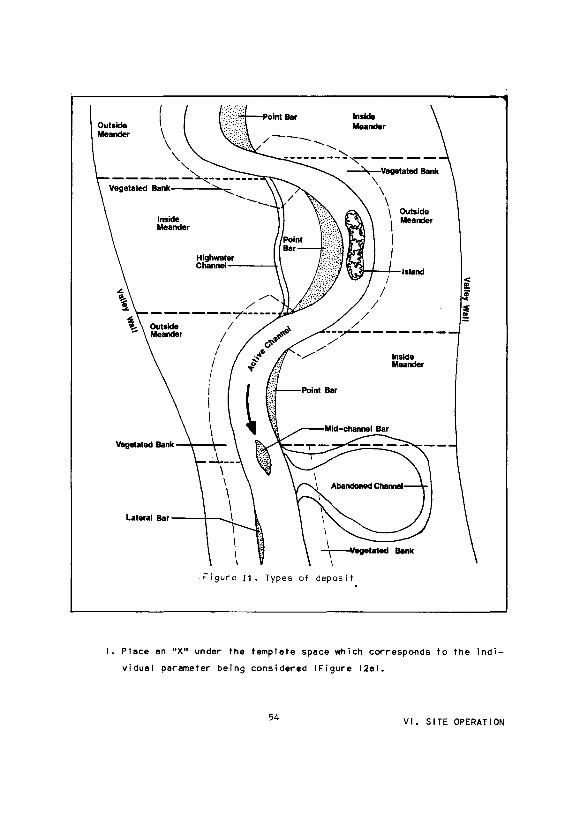
Braided Rivers. A braided river typically contains two or more inter
connecting channels separated by unvegetated gravel bars or vegetated islands
!Figure 9al. Its floodplain is typically wide and sparsely vegetated, and
contains numerous high-water channels. Bars separating the channels are
usually low, gravel surfaced, and easily eroded.
Split Channel Rivers. A split channel river has numerous stable islands
which divide the flow into two channels !Figure 9bl. There are usually no
more than two channels at a given reach and other reaches are single channel.
The banks of the channel lsi are typically vegetated and stable. The split
river floodplain is typically narrow relative to the channel width.
Meandering, Sinuous, and Straight Rivers. Meandering and sinuous rivers
!Figures 9c and 9dl have a single channel that winds back and forth within
the floodplain; straight rivers wind less. Very few islands are found in
these systems. Point bars and lateral bars are common, with point bars more
frequent in meandering rivers and lateral bars in straight rivers. Banks on
the outside of a bend in a meandering river are normally unstable whereas the
banks of a straight river are relatively stable. The floodplains of mean
dering and sinuous rivers are usually as wide as the meander belt, and there
fore, are narrower for sinuous rivers than for meandering rivers. Floodplains
of straight rivers are narrow.
Template Preparation
Required Data. After the proper matrix has been identified, the template
describing the work plan can be prepared. A template can either be prepared
by: I I I using the blank template provided in the back of this manual, or 121
aligning a blank sheet of paper under the parameter descriptions of one of the
51 VI. SITE OPERATION

b. Split Channel River
c. Meandering River
d. Sinuous River
Figure 9 . Examples of river configurations !straight rivers are similar to sinuous but with a lower sinuosity ratio) .
52 VI. SITE OPERATION
matrices, drawing I ines on the blank sheet to correspond to those of the
heading columns and identifying each parameter in its proper position. An
example of a template wi I I be shown later !Figure !2al. To fi I I out the tem
plate the following information is required:
$' ~
• The size of the river at which the mining operation wi I I be conducted
!smal I, medium, or large!
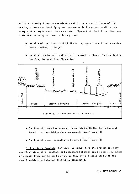
• The site location or locations with respect to floodplain type !active,
inactive, terrace! !see Figure 101
Terrace
~ c
"' .I:: ()
Inactive Floodplain
VJ Qj c: c
"' .I:: ()
Active
VJ Qi c c
"' .I:: () Q) >
~ ,...--...,
I
Floodplain
Figure 10. Floodplain location types.
I r !Terrace
• The type of channel or channels associated with the desired gravel
deposit (active, high-water, abandoned! (see Figure I I l
• The type of gravel deposits to be mined tsee Figure ! I I
I_ a; 3:
"' .B!
I~
Fi I I ing Out a Template. For each individual template evaluation, only
one river size, site location, and associated channel can be used. Any number
of deposit types can be used as long as the.y are alI associated with the
same floodplain and channel type being considered.
53 VI. SITE OPERATION
Outside Meander
Inside Meander
/--- .............
Highwater Channet-------1-
--------~~----~Vegetated Bank
\ \ \ 1 Outside \ Meander
I J
\i.:~H-~Island I ~
I 1 I
/ ~ /
--~-------/
/ '/ Inside
I
\ I I ~egetated
\
Meander
Fl gure II. Types of deposit
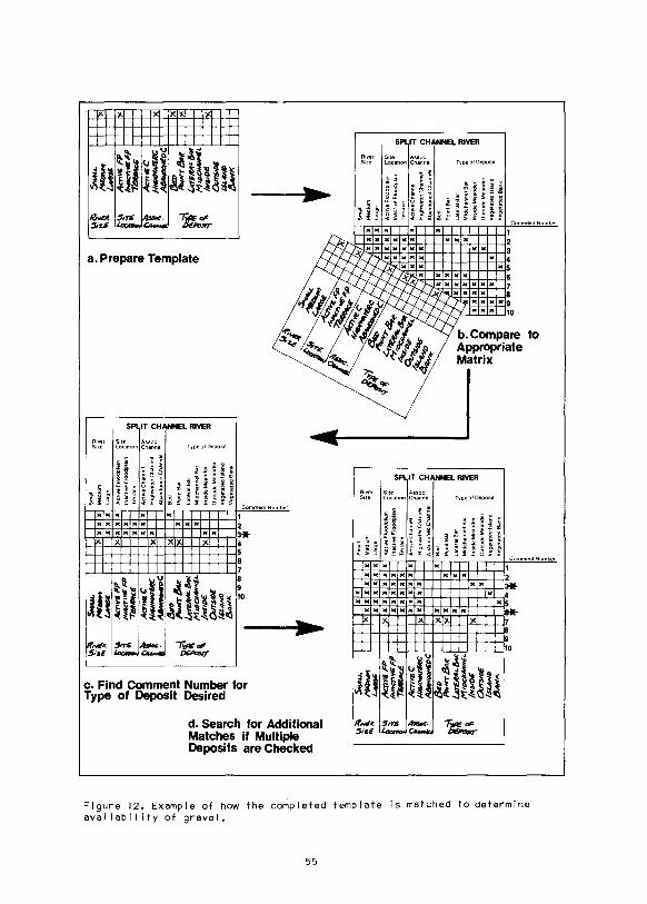
I. Place en "X" under the template space which corresponds to the indi
vidual parameter being considered !Figure 12al.
54 VI. SITE OPERATION
\.n
\.n
"' ,
< -
· <
»<D
-·
c
_.,
"' ..
0' -"'
.... -<rT
l X
0
"'
~3 .,
<D
-
., ..
"' < 0 .. ~
::r ~ .... ::r .. ()
0 3 ., .. .... .. a. .... .. 3 ., "' .... .. "' 3 "' .... (
)
::r .. a. .... 0 a. .. .... .. ., 3 ::>
..
i3l:
!l
'8 ~H
e !i'~
flll
ll::
r
~~~-
·
iili
~ O
E.l
>
%:::
:8:
n"2.
-· ~CD:::
a g
Il
l
~f .. ,. \!1 0\ f ~
-tn
'<
' 'g
.,
~:
"'"'
CD
-·
:I
oa
. -o
r§
~ f !II
i ==
a ~~
-·3
~i
&~
I! 0'
~
5ooo
u.
,.,.,....,
'-
-M
tV6
FP
/N
AC
TIV
£FP
T~
Am
vsC
~~~
~c
~!-r&.(
=.
11 II"I
+H ~:::
m ~
) X
XX
L
arg
e
~·· F
P I li
lT IT
I '"'" ""
""" /'
V4
Cf'
14
~p
X
X
lna
cto
ve F
loo
dp
lam
'TU~
X
X
Te
rra
ce
Acn~ C
X
X
X
A
ct1
veC
ha
nn
ol
}(~
)(X
H
1g
hw
ate
rCh
an
ne
l
~C
Ab
an
do
ne
dC
ha
nn
el
&o
X
X
eed
,.,N'f" ~
')( X
P
oont
Ba
r
/Jrr
PIN
-/JM
X
M
1/JO
IJIN
NE
L
X
/NSt
o£
Otn
s«
/.U
AN
D
fjm
t"
)(IX
M•d
cha
nn
eiB
ar
lns•
de
Me
an
de
r
Ou
tsid
e M
ea
nd
er
Ve
ge
tate
d I
sla
nd
Ve
ge
tate
d B
an
k
~ ~(Do:~...,cnu..ao-
• ...,
.....
1~
X
X
Sm
all
-"-f
'f"-
j-",
f"+~
M
ed1u
m
Larg
e
~ 2 j ~
""
;q
)(IX
IXIX
IXIX
IX
~~~~:.
::~,::
:;,:,,
[~
l(jX
I_X
_llC
jX
iTiT
iTiT
i T
err
ace
g
., Jl
:i!j"jx
1xjxjx
jxj "'
"'c"""
" n•
:::; i
X
X I X
X
H
igh
wa
ter
Cn
an
ne
l ~ ~
n
A
ba
nd
on
ed
Ch
an
ne
l .:__~
T:x
X
X
Bed
J!! "' )(
X
X
P
om
tBa
r
X
X
La
tera
iBa
r
X
X
Mld
cha
nn
eiB
ar
UrS
/fA
L /J
M
Mri
1C/I
AN
N€1
. /N
.,o
£
Our
.siD
6 IS
UN
D
Tx
X
lnsl
de
Me
an
de
r
~~
X
Ou
ts•d
e M
ea
nd
er
~
"'"""
X
Ve
ge
tate
dls
lan
d
X
VeQelatedBan~
"; .
. "lf
''-
""
~ ~ ~~
!(!
~[ 2
=--1
£
<'
~ I • ~ "' ~
t~''
~
~~
J$:~
;>
~~
~.,
;;,~~ (
',
"'~~
~ /L
'" <
Ill 'll iil '2 iil ~
3 l
n ~
0\ l ~ v !lW
<_
iT
iTi
La
rge
s.-L
,.,_
..., '-
-A
cn>
E F
P
~p
Acn
"'C
JI-
7U
lC
A-D
C
/3tto
I+
HN
T/!!
itl(
Ur6
/fAL/
JM
M1~1f/1#16L
'"'"06
C
Nrs
to6
/SI.
"'""1( ~ ""
~ ~
Actt~eFioodpla•n
g~
i-._
,8-:
;+:'f
"H ~
n;~:~: F
loo
dp
lam
~
XI X
IX I
X
~
~"""
~ H
rgh
wa
ter
Ch
an
ne
l ~ ~
n
A
ba
nd
on
ed
Ch
an
ne
l .:.__~
Ax
x
XB
ect
'j-...
X
X
X
Po
mtB
ar
z J!!
----
5: l>
0"
~l~
'f-....
X
X
X
X
La
tera
l Ba
r
"'-
-'
X
X
X
X
M•d
cha
nn
el
Bar
~ -·
i ;;
0
X
X
X X
X
ln
s•d
e M
ea
nd
er
X
X
X
X
X
Ou
tsid
e M
ea
nd
er
X
X
X
X
Ve
ge
tate
d I
sla
nd
IX
X
Ve
ge
tate
ctB
an
k
iS"'
....
G:I
U.A
c.J·
...,
--:.
...
~ " l2i X
B
2. When the template is complete, compare the template to the appropriate
matrix !Figure 12bl.
3. Follow down the matrix unti I river size, site location, associated
channel, and one deposit type are matched !Figure 12cl. Record Comment
Number.
4. If more than one deposit has been "X"ed, continue down until another
match is found, then record Comment Number !Figure 12dl.
5. After alI deposit types have been matched, read the appropriate guide-
1 ines Commentlsl to determine if and how gravel is avai I able. Specific
mining guide I ines are referenced.
6. Repeat steps I to 5 for other combinations of floodplain and channel
type.
56 VI. SITE OPERATION

\J1 -.J
<
c.n
'"" "' 0 'U
"' JJ )>
'"" 0 z
I
BRAIDED RIVERS- MATRIX I
River Site Associated size location channel Type of deposit
c ·- -
c "' Q) -·- - c Q) "0
"' 0. c c L L c - "0 - "' c "' L Q) "' 0. 0 Q) .c "' .0 Q) "0 -"0 0 c u .c "0 c U1 0 - c u L - c "' ·-0 - "' L "' Q) "' Q) - .c Q) "0 L .0 c <]) E "0 - <]) u -:o
Q) "' c E Q)
> Q) c .0 - "' <]) ~
E Q) ·- u Q) 3: 0 "' .c Q) "0 "' - :J Q) > ~ "' > I "0 ~ L u "0 ·- ~ - ·- 0> ·- u L ·- .c c c Q) I ·- U1 Q)
"' "0 L ~ "' L ~ 0> "' "0 ~ "0 U1 ~ 0> E Q) "' u c Q) u ·- .0 Q) 0 "' c :J Q)
<JJ ::;: _J <( - f- <( I <( ro o._ _J ::;: - 0 >
X X X X X X
X X X X X X X
X X X X X X X X X
X X X X X X X X X
X X X X X X X X
X X X X X X X X
X X X X X X X X X
X X X X X X X X X X
aExpanded comments begin on following page.
I
I I
"" c
"' .0
I
"0 Q) ~
"' ~ Q)
! 0> Q)
> Comments a
I. Gravel may be avai I able by scraping or dredging.
! 2. Grave I available by scraping.
3. Gravel avai I able by scraping.
4. Genera II y shou I d not be mined.
X 5. Banks should not be mined.
6. Gravel available by scraping.
7. Gravel available by scraping.
X 8. Gravel available by scraping or pit . mining.
Expended Comments for Braided Rivers
Comment I. Generally, the bed of en active channel should not be dis
turbed. If bed deposits ere the only evei leble source, the gravel should
be taken only under strict work plans end stipulations.
• It is recommended that side channel lsi be mined rather then the main
channel. Select side channel lsi that carry less then approximately
one third of the total flow during the mining period; block off up
stream ends end mine by scraping operations. Refer to Scraping Guide
lines lVI B 21.
• If the main channel must be mined, dredging mey be en appropriate
method. Refer to Dredging Guidelines lVI B 41.
Comment 2. Greve I is evei leble by scraping gravel deposits to neer the
low summer flow, maintaining eppropriete buffers, or no lower then the weter
level present during the mining operation. Refer to Scraping Guide I ines lVI B
21.
Comment 3. Gravel is evei leble by scraping such that the configuration
of the channel is not greatly changed end there is not e high probebi lity
of channel diversion through the mined eree. Refer to Screping Guide I ines
lVI B 21.
Comment 4. Vegetated islands ere often e limited hebltet in these systems
end should generel ly be excluded from the work plen. Exposed deposits should
be considered before vegetated island deposits. If deposits in feasible alter
native locations ere not sufficient, end vegetated islands ere abundant in the
particular reech in question, up to about 10 to 20 percent of this hebitet may
be removed from about e given 5-km length of the floodplain. Refer to Scraping
Guidelines lVI B 21 or Pit Guidelines lVI B 31.
Comment 5. Vegeteted river banks of both active end high-water channels
should not be disturbed because of biological end hydraulic elteretions.
These should be removed from work plans.
56 VI. SITE OPERATION

Comment 6. Gravel is available by scraping within the channel, but the
general configuration of the channel should be maintained. Refer to Scraping
Guide! ines lVI B 21.
Comment 7. In these systems it is recommended to scrape exposed deposits
in the active floodplain. If sufficient gravel is not avai I able in the pre
ferred deposits, gravel may be avai I able by scraping in these locations, but
the general configuration of the channel should be maintained. Refer to Scrap
ing Guide I ines lVI B 21.
Comment B. In these systems it is recommended to scrape exposed deposits
in the active floodplain. If sufficient gravel is not available in the pre
ferred deposits, gravel is avai I able in these locations by either pit or
scrape methods. Generally, pits should only be considered when more than
50,000 m3 are required. Refer to Scraping Guidelines lVI B 21 and Pit Guide-
! ines lVI B 31.
59 VI. SITE OPERATION
ON
01 0
<
(/l
"" rn
0 ~ rn ~ >
""
--co E
(f)
lx lx
lx lx lx
River size
E :::> ~ ·-"0 1..
"' co
"" _J
X X
X X
X X
X X
X X
X X
X X
X X
Site Associated location channe I
c -c co "' -·- - c "' co a. c c - "0 - co c a. 0 "' .c co "0 0 c u .c 0 - c u 0 - co 1.. - .c "' "0 - "' u .... "' > "' co c "' ·- u "' 3: 0 > .... co > I "0 ·- u 1.. ·- .c c .... co 1.. .... "' co u c "' u ·- .0 <( - f- <( I <(
X X
X X
X X X X X
X X X X X
X X X X X
X X X X
X X
X X X X
X X X
X X
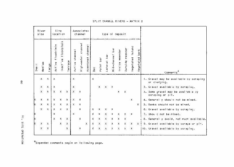
SPLIT CHANNEL RIVERS- MATRIX 2
Type of deposit
"0 1.. 1.. c co 1.. "' co :<. .0 "' "0 - c
"0 c <Jl co 1.. - c co ·- .0 co "' co "' 1.. .0 c "' E "0 "0
co c E "' "' .0 - co "' .... .... co .c "' "0 co co .... 1.. u "0 .... ....
c "' I ·- <Jl "' "' "0 .... "0 <Jl .... "' "' "' 0 co c :::> "' "' lil 0.. _J
"" - 0 > >
X
X X X
X X
X
X
X X X X
X X X X X X X
X X X X X X
X X X X X X X X
X X X X X X X
~ aExpanded comments begin on following page.
Comments a
I. Gravel may be avai labiP by scraping or dredging.
2. Gravel available by scraping.
3. Some gravel may be available by scraping or pit.
4. Genera I I y shou I d not be mined.
5. Banks should not be mined.
6. Gravel avai I able by scraping.
7. Should not be mined.
8. Generally avoid, not much available.
9. Gravel avai I able by scrape or pit.
10. Gravel avai I able by scraping.
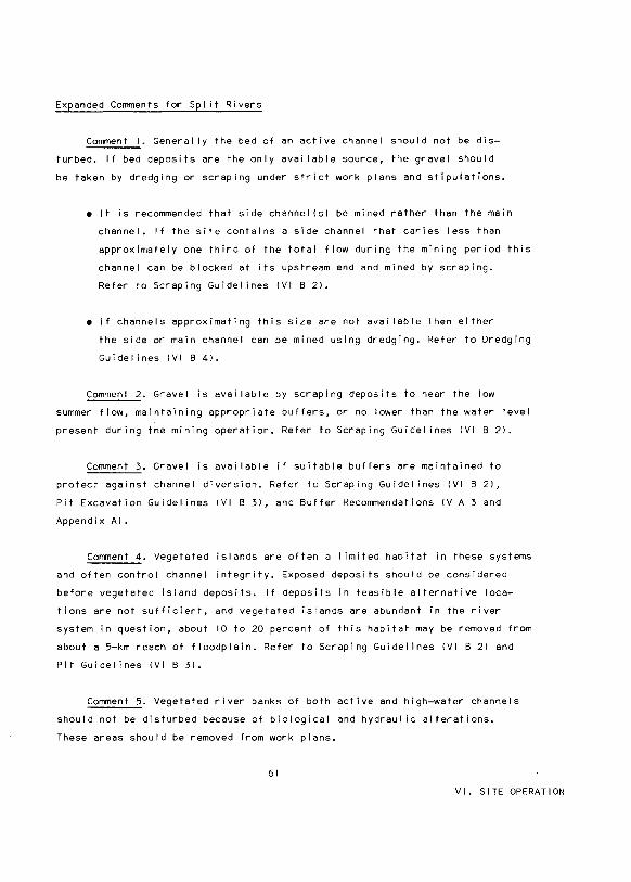
Expanded Comments for Split Rivers
Comment I. Generally the bed of an active channel should not be dis
turbed. If bed deposits are the only avai I able source, the gravel should
be taken by dredging or scraping under strict work plans and stipulations.
• It is recommended that side channel lsi be mined rather than the main
channel. If the site contains a side channel that caries less than
approximately one third of the total flow during the mining period this
channel can be blocked at its upstream end and mined by scraping.
Refer to Scraping Guide I ines lVI B 21.
• If channels approximating this size are not avai I able then either
the side or main channel can be mined using dredging. Refer to Dredging
Guide I ines lVI B 41.
Comment 2. Gravel is avai I able by scraping deposits to near the low
summer flow, maintaining appropriate buffers, or no lower than the water level
present during the mining operation. Refer to Scraping Guide! ines lVI B 21.
Comment 3. Gravel is avai I able if suitable buffers are maintained to
protect against channel diversion. Refer to Scraping Guide! ines lVI B 21,
Pit Excavation Guide! ines lVI B 31, and Buffer Recommendations IV A 3 and
Appendix AI.
Comment 4. Vegetated islands are often a I imited habitat in these systems
and often control channel integrity. Exposed deposits should be considered
before vegetated island deposits. If deposits in feasible alternative loca
tions are not sufficient, and vegetated islands are abundant in the river
system in question, about 10 to 20 percent of this habitat may be removed from
about a 5-km reach of floodplain. Refer to Scraping Guidelines lVI B 21 and
Pit Guide I ines lVI B 31.
Comment 5. Vegetated river banks of both active and high-water channels
should not be disturbed because of biological and hydraulic alterations.
These areas should be removed from work plans.
61
VI. SITE OPERATION
Comment 6. Gravel is avai I able by scraping in the high-water channel,
but precautions must be taken to avoid channel diversion. Refer to Scraping
Guidelines lVI B 21.
Comment 7. Mining is not recommended in or near the active channel of
smal I split channel rivers because there Is not much material avai I able.
Comment B. There generally is not much material avai I able in these de
posits and they should be avoided. If only a smal I amount 1<10,000 m3 1 of
gravel is needed, these deposits may be considered for scraping. Refer to
Scraping Guidelines I IV B 21.
Comment 9. Gravel is avai I able by either pit or scrape methods. Generally
these should be considered for large amounts of gravel that are not present
in adequate amounts in exposed deposits. Pits should be considered when more
than 50,000 m3 are required. Refer to Scraping Guidelines lVI B 21 and Pit
Guidelines lVI B 31.
Comment 10. Some gravel is avai I able by scraping, but the general config
uration of the channel should be maintained. Refer to Scraping Guide I ines
lVI B 21.
62 VI. SITE OPERATI~
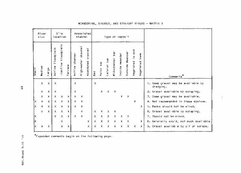
MEANDERING, SINUOUS, AND STRAIGHT RIVERS- MATRIX 3
0\
"'
i
I
--., E
If)
X
X
X
X
X
River size
E :::1 "' 0"> "0 '-"' ., .. __J
X X
X X
X X
X X
X X
X X
X X
Site location
c ·-c .,
·- -., Q. - "0 Q. 0 "0 0 0 -0 ~ -~ "' > "' "' ·- u > ~ ., ·- u '-~ ., '-u c "' < - f--
X
X
X X X
X X X
X X X
X X X
X X X
X
X X
Associated channel Type of
a; a; c c c '-- ., c .,
"' .s:; ., .0 c u .s:; c u '- -., '- .,
"' .s:; "' "0 '- .0 c u ~ "'
., c ., c .0 -;;; ., "' ;: 0 .s:; > I "0 ~ '- u ·- .s:; c c "' I ~ 0"> "' "0 ~ "0 u ·- .0 "' 0 ., « :r: « co "- __J .. X X
X X X X
X X
X X
X X
X X X X X
X X X X X X
X X X X X
X X X X X
< aExpanded comments beg,in on the following page.
Ul
_.., rn
0 .., rn ;l) )> _..,
0 z
deposit
"0 '- c
'- "' ., -'£
"' "0 - c "0 c "' ., c ., ·- .0 ., "' "' .. "0 "0 E "' "' "' ~ ~
"' "0 ., ., "0 ·- ~ ~
·- "' "' "' "' ~ 0"> 0"> c :::1 "' "' - 0 > > Comments a
I. Some gravel may be avai I able by dredging.
2. Gravel avai I able by scraping.
X X 3. Some gravel may be available.
X 4. Not recommended in these systems.
X 5. Banks should not be mined.
6. Gravel avai I able by scraping.
X X 7. Should not be mined.
X X X 8. Genera I I y avoid, not much available.
X X X X 9. Gravel available by pit or scrape.

Expanded Comments for Meandering, Sinuous, and Straight Rivers
Comment I. Generally the bed of an active channel· should not be dis
turbed. If bed deposits are the only avai I able source, the gravel should
be taken by dredging only under strict work plans and stipulations. Refer
to Dredging Guidelines lVI B 41.
Comment 2. Gravel is avai I able by scraping deposits to near the low
summer flow, maintaining appropriate buffers, or no lower than the water level
present during the mining operation. Refer to Scraping Guide! ines lVI B 21.
Comment 3. Gravel is avai I able if suitable buffers are maintained to
protect against channel diversion. Refer to Scraping Guide I ines lVI B 21,
Pit Guide I ines lVI B 31, and Buffer Recommendations IV A 3 and Appendix AI.
Comment 4. Vegetated islands are rare in these river systems and should
not be disturbed. It is recommended they be removed from the work plan.
Comment 5. Vegetated river banks of both active and high-water channels
should not be disturbed because of biological and hydraulic alterations. These
areas should be removed from the work plan.
Comment 6. Gravel is avai I able by scraping in the high-water channel,
but precautions must be taken to avoid channel diversion. Refer to Scraping
Guidelines lVI B 21.
Comment 7. Mining in the active or high-water channels of these smal I
rivers is not recommended because there is not much material avai I able.
Comment B. There generally is not much gravel avai I able in these deposits
and they should be avoided. If only a smal I amount 1<10,000 m3J of gravel
is needed, scraping may be considered. Refer to Scraping Guide I ines lVI B-21.
Comment 9. Gravel is avai I able by either pit or scrape methods. Generally
these areas should be considered for large amounts of gravel that are not
64 VI. SITE OPERATION

present in adequate amounts in exposed deposits. Pits should be considered
when more than 50,000 m3 are required. Refer to Scraping Guide! ines lVI B 21
and Pit Guide! ines lVI B 31.
2. Specific Guide! ines for Scraped Sites
a. Gravel bars adjacent to high-water and abandoned channels can
be scraped to a specified level at the edge of the channel and
should be sloped toward the channel to provide proper drainage.
An average maximum depth should be maintained in the channel to
provide for flow containment during periods of low flow within
the channel. The average maximum depth at any point along the
channel is the distance between the average thalweg profile I ine
and the channel-ful I stage at that point !Figure 131 .
..... f!Jannel~r
Thalweg Profile Averf!!Je Thalweg Profile
Channel Thalweg Cross Section A-A
Figure 13. Definition of average maximum depth and channel-ful I width in a channel.
Recommended values of maximum depth that should be maintained in
the channel are I isted below for three ranges of channel-ful I
width. Values of half the recommended depths should be considered
minimum depths below which flow containment would be ineffective.
65
VI. SITE OPERATION
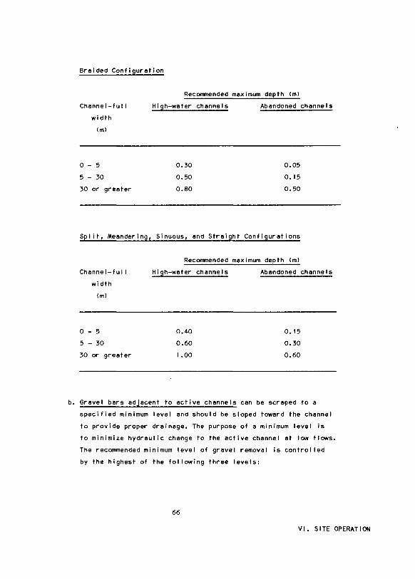
Braided Configuration
Recommended maximum depth lml
Chennel-ful I
width
lml
0 - 5
5 - 30
30 or greater
High-water channels
0.30
0.50
0.80
Abandoned channels
0.05
0.15
0.50
Split, Meandering, Sinuous, end Streight Configurations
Recommended maximum depth lml
Channel-full
width
lml
0 - 5
5 - 30
30 or greater
High-water channels
0.40
0.60
1.00
Abandoned channels
0.15
0.30
0.60
b. Gravel bars adjacent to active channels can be scraped to a
specified minimum level and should be sloped toward the channel
to provide proper drainage. The purpose of e minimum level is
to minimize hydreul ic change to the active channel at low flows.
The recommended minimum level of gravel removal is control led
by the highest of the following three levels:
66
VI. SITE OPERATION

• The upper level of the low-flow buffer. This is defined
in Site Preparation Guide! ines IV A 3al
• The level corresponding to 0.15 m above the average water
level expected during the gravel removal operation
• The level thet wi I I maintain a specified averaye maximum
depth in the channel !Figure 131. Recommended values end
minimum values of maximum depth thet should be meinteined
are I isted below for three channel width ranges et chennel
ful I flow. Values of helf the recommended depths should be
considered minimum depths below which hydraulic change is
more likely to occur.
Braided Configuration
Channel-ful I Recommended
width maximum depth
lml lml
0 - 5 0.30
5 - 30 0.50
30 or greeter I .00
Split, Meandering, Sinuous, end Streight Configurations
Chennel-ful I Recommended
width maximum depth
lml lml
0 - 5 0.50
5 - 30 I .00
30 or greeter I .30
67
VI. SITE OPERATION

c. Scrapi~g In high-water and abandoned channels should follow
the alignment of the channel. Gravel removal design depends
on several factors listed below:
• Side slopes should be steble for expected flow conditions
during a 2-year recurrence interval flood. This wil I reduce
the potential for rapid channel shifting.
• Channel-ful I top width should not be increased if it can
be avoided. If additional material Is needed that cannot
be obtained from other dry channels or unvegetated bars,
the channel being worked cen be widened to e width no greater
than thet of the active channel and preferably half that of
the ective channel (especially on meandering, sinuous, end
straight rivers!.
• Longitudinal channel slope into the materiel site should not
exceed 10 times the average slope of the channel (Figure 141.
This wi I I minimize the potential for extensive upstream bed
degradation. The upstream end of the section of increased
slope should be a sufficient distance from the nearest active
channel to minimize the potential for channel diversion.
Top of Ad;acent Bar or
Figure 14. Sketch of high-water or abandoned channe I I ong i tud ina I profile showing recommended channel bed slopes resulting from 'scraping the channel bed.
68
VI. SITE OPERATION

• Longitudinal channel slope out of the materiel site et the
downstream end should not be adverse (bed elevation in
creasing in the downstream direction). Adverse slopes cause
ponding end potential fish entrapment. Maintaining e positive
slope (bed elevation decreasing in the downstreem direction)
Is recommended to el low for channel drelnege during e flood
recession. The downstream end of the disturbance should be
separated from the nearest active channel by et least the
width of the low-flow buffer for thet channel !Figure 141.
d. Scraping in active side channels thet have been diked end de
watered should follow the alignment of the channel end should
stey between the low-flow buffers. Gravel removal design depends
on other related factors listed below.
• Side slopes should be stable for expected flow conditions
during e 5-yeer recurrence interval flood. This wil I minimize
the potential for slope fei lure end subsequent deterioration
of the low-flow buffer.
• The width of excavation is limited by the limits of the
low-flow buffers !Figure 151. The bottom width Is limited
only by the equipment used.
Low Summer Flow Stage
Excavation Width
Stable Side Slopes ·--v~J
Figure 15. Sketch of active side channel cross section defining excavation I imitations.
69 VI. SITE OPERATION
• Ch8nnel slope into and out of the m8teri81 site should be
st8ble under alI flow conditions up to 8nd including 8 5-ye8r
flood. This wi I I minimize the potential for bed degradation.
• The existing pool-riffle sequence should be retained during
the gravel remov81 operation. If it is disturbed, a simil8r
sequence should be restored following the operation.
• Active ch8nnels scheduled for winter scraping should be
evaluated for the presence of flowing w8ter in and downstream
from the site; if water is present, the site should not be
mined.
e. Mining of high-water or abandoned channel bed 8nd 8Ssociated bars
should follow Guidelines VI B 2c and VI B 28, in that order, if
sufficient gr8vel quantities 8re not avai I able from only one of
these sources. If sufficient gr8vel qu8nt it ies are st iII not
av8i lable and channels are not 8bundant, or if high-water or
8bandoned ch8nnels are not 8V8i I able, it m8y be necessary to form
new wei 1-define~ channels following Guide I ine VI B 2c. High-water
channels formed during the gravel mining operation should h8ve an
alignment similar to that of n8tur81 high-water channels or the
active channellsl of the river.
3. Specific Guidelines for Pit-Excavated Sites
A profile 8nd configuration of the work area should be m8intained
to pro vi de:
a. A minimum surface area of 2.0 h8. Inundated pits sm81 ler th8n
this size 8re generally not he8vi ly uti I ized by w8terfowl. I I
the pit is connected to the river, a mean depth of 2.5 m or
greater should be provided to insure winter surviv81 of fish.
70
VI. SITE OPERATION
b. A relatively long and narrow shape aligned longitudinally in
the floodplain and providing an irregular configuration with
islands and peninsulas is preferable !Figure 16a and 16bl
• Islands and low peninsulas provide more diverse shore I ine
and aquatic habitats
• If the river does divert through the pit, it will have an
alignment to follow and wi I I more quickly develop into a
channel configuration
c. An outlet channel for a path of low resistance when the pit is
inundated, reducing erosion of undisturbed terrestrial habitat.
An outlet channel also provides an avenue of escape for fish
which may become trapped during high flows.
• Outlet channels should be deep enough to allow fish passage
during low flow conditions and be as narrow as possible
• AI I outlet channels should be on the downstream end of the
pit to prevent premature degradation of the stream channel
and pit
• Outlet channels should be connected to a non-depositional
area of an active channel and be angled downstream
• Outlet channels should not be of straight I ine configuration
• Outlet channels should be constructed at the end of the
site closure to minimize si I tat ion in the river
d. A diversity of water depths and bank slope
• At least 30 to 50 percent of the shore I ine should have a
gradual slope to provide areas for emergent aquatic vegeta-
71
VI. SITE OPERATION

a. Aerial view of an acceptable pit configuration.
Marsh/ Littoral Area\ LowlandZ
b. Side view of an acceptable depth regime (Section A -A).
Figure 16. Example of a preferred shape and depth profile of gravel pits in. floodplain terraces and connected to the active channel.
72 VI. SITE OPERATION
tion, shorebird and waterfowl feeding, juvenile fish rearing,
and muskrat habitat !Figure 16bl. The gradual slope of these
areas should allow a natural transition of vegetative com
munities and provide exposed mud flats or the potential
for future marsh habitat development.
• The remaining shore I ine should be more steeply sloped to
provide habitat more beneficial to other groups such as
diving ducks, geese, swans, beaver, and adult fish
• As mentioned above, a mean depth of 2.5 m or greater of
combined I ittoral and deep areas should be provided if there
is an outlet channel or if a non-connected pit is to be
managed for fish. For example, 25 percent littoral area
averaging 0.5 m and 75 percent deep area averaging 3.2 m
yields an overal I mean depth of 2.5 m. Refer to the Pit
Design Appendix D.
• In a pit not connected to the active channel, and not to be
managed for fish, a similar shape and depth configuration is
appropriate, but a mean depth of 2.5 m is not required. These
pits should be protected with an adequate buffer from flood
ing so that fish entrapment is minimized. In this case, the
main purpose is the creation of shorebird and waterfowl
habitat.
• If there is a choice between mining to a shallow depth over
a broad surface area or deep over a restricted surface area,
the choice should be to increase depth before increasing
area. This minimizes terrestrial disturbance and reduces the
probability of fish winter mortality.
73
VI. SITE OPERATION
4. Specific Guidelines for Dredged Sites
a. Active channels scheduled for winter dredging should be evaluated
for the presence of flowing water in and downstream from the
site; if water is found, the site should not be mined
b. Depth of excavation in en active channel should be limited by
the width of the low summer flow channel minus the low-flow buf
fer; the side slopes should be designed to remain stable during
5-yeer flood flows
c. The length of excavation in e pool of the active main channel
should not exceed the length of the pool. If a riffle is to
be mined, the length of excavation should not exceed the average
length of the pools within 5 km up en~ tiownstream of the site.
d. The bed slopes et the upstream end downstream ends of the active
channel excavation should be designed to remain stable during
5-year flood flows to minimize the potential for degradation
74
VI. SITE OPERATION
Site Closure Section VII
GENERAL GUIDELINES •
SPECIFIC GUIDELINES
Scraped Sites
Pit-Excavated Sites
Dredged Sites
Page
76
80
80
80
81

A. GENERAL GUIDELINES
Site Closure Section VII
After mining is completed, material sites should be rehabi I itated to
return them, as closely as is possible, to pre-mining condition.
I. The site should be sloped and contoured immediately following comple
tion of operations. In cases where sites consist of two or more
al iquots, each should be sloped and contoured as completed. Any
seeding and ferti I izing should be done in spring or summer.
2. The work area should be shaped and contoured to minimize pending
and to blend with surrounding features and topography
3. Access roads, culverts, and bridges should be removed !unless other
wise approved! and the areas restored. Fi I I ramps at incised banks
should also be removed and the bank stabilized I if damaged! to
minimize subsequent erosion.
4. AI I manmade debris should be removed from the site
5. AI I cut slopes encountered during gravel removal or access road
construction should be stabilized to prevent thermal, fluvial, and
wind erosion
6. Dewater settling ponds of the clear surface water either by pumping
or lowering dikes. Silt may be:
• Left in place in inactive floodplains and terrace locations;
protective structures should be lowered to a level corresponding
to the level of the impounded si It
76 VI I. SITE CLOSURE

• Broadcast or pi led with other overburden and vegetative slash
and debris !refer to guideline VI I A 71
• Removed from active floodplain sites to approved disposal areas
7. In general, at sites that were previously vegetated and wi I I contain
nonflooded areas following site operation, rehabilitation should
feci litate natural revegetation and site recovery. When organic
overburden and vegetative slash and debris are avei I able, it is
recommended that natural revegetation be favored over artificial
seeding and ferti I ization. Final placement of overburden and vege
tative slash end debris should incorporate the following guidelines.
e. Active floodplains
i I In braided systems it is unlikely that any overburden or
vegetative slash and debris wi I I be avai I able. However, if
avai I able it should not be pi led within the active flood
plain.
iil In meandering, sinuous, split, and straight systems this
material may be pi led within the active floodplain. The
design and I oct ion of these piles should incorporate
the following !Figure 171. They should be:
• Located away from active channels and in areas where
they are subjected to the least hydraulic erosion
• Long and narrow in configuration !about 15-20 m long
and 3-5m wide, where possible!
• Orientated para I lei to the flow
• About I m above the 2-year recurrence flood at its top
77 VI I. SITE CLOSURE

Temporary Pile Shape. During Operation (Refer to Fig. B)
Pile at Closu
3-Sm Wide
Figure 17. Typical view of desirable shape end configuration, relative to 2-yeer flood levels, of permanently pieced overburden piles.
• Armored.on the active side to prevent erosion !refer
to discussions of bank protection in Appendix Cl
• PI led to maximize surface area, provided this meets
the above criteria
If sufficient materiel exists, it Is desirable to produce
several piles distributed throughout the mined area.
If insufficient materiel exists to meet the above cri
teria, it should not be pi led within the active flood-
78 VI I. SITE CLOSURE
plain. If insufficient space exists within the mined
area away from the active channel, this materiel may
be used either in site rehabilitation of adjacent materiel
sites or disposed of in approved upland areas.
ii il Neither artificial seeding nor ferti lizetion should be
conducted in active floodplains
b. Inactive floodplains and terraces
At these locations in rivers of alI configurations this ma
terial may be either pi led or broadcast over the ground surface
i l At sites consisting only of inactive floodplains that
are annually flooded it may be best to pile this ma
terial rather than broadcast it to reduce downstream
transport. If pi led, the guide I ines presented above
17al should be followed.
ii l At sites including terraces and inactive floodplains
that are not annually flooded, this material should
be broadcast throughout these portions of the mined
site. In general, this material should be spread about
10 em deep and should cover as large an area as pos
sible.
iii l If this material is not avai table for use in site reha
bilitation of terraces and inactive floodplains, arti
ficial seeding and fertilization may be considered
and should follow current state-of-the-art techniques
for arctic and subarctic regions
79 VI I. SITE CLOSURE

B. SPECIFIC GUIDELINES
I. Specific Guidelines for Scraped Sites
8. Distribute coarse gravels or cobbles, when available, over the
surf8ce of the gr8vel removal area, to provide for a more r8pid
re8rmoring of the surf8ce
b. If the low-flow buffer was disturbed, return it to its natural
configur8tion and height
c. At side channel sites which were diked to work in a dry con
dition, remove the downstream dike and lower the upstream dike
to a level corresponding to the river stage of a 1.25-year flood.
Tbis wi I I prevent large quantities of sediment from being washed
from the site into the river 8t low-flow conditions.
2. Specific Guidelines for Pit Excav8ted Sites
a. Overburden and vegetated slash and debris should be:
• Broadc8st or pi led, or both, in the nonflooded portions of
the mine site, including islands and shore I ines
• If any materi81 remains, some may be pl8ced in the flooded
portion of the site to provide nutrients and cover
b. Slope and contour shoreline b8nks and alI overburden stockpiles
in nonflooded portions of the mined area to provide naturally
appe8ring configurations th8t blend with surrounding features.
These procedures should provide and maintain those characteris
tics of diverse shore! ine configurations and profile, bank slope,
and water depth as discussed in previous operation guide I ines.
80
VI I. SITE CLOSURE
c. Excess unused mined material should be used to form islands
or vary water depths within the pit
d. Follow work plan regarding access to the pit
e. The outlet channel, if provided in work plan, should be con
structed during the final phases of site closure. Refer to Opera
tions Guide! ines for design criteria !Section VI B 3cl.
3. Specific Guide I ines for Dredged Sites
If the low-flow buffer was disturbed, return it to its natural config
uration and height
81
VI I. SITE CLOSURE

SEK)!pueddy
Appendix Pege
A. FLOOD-FLOW BUFFER DESIGN • 84
B. FIELD INSPECTION: Desirable Dete, Procedures end Equipment • • • • • • • • • . . . • • 107
C. RIVER-TRAINING STRUCTURES AND BANK PROTECTION DEVICES • • • • • • • • . . . I 17
D. DESIGN OF PITS • • • • • • • • • • • • • 127
E. FISH PASSAGE STRUCTURES • • • • • • • • 131
F. SETTLING PONDS AND WASTEWATER TREATMENT • • • • • • . . • • • • • • • 135
G. EFFECTS OF BLASTING ON AQUATIC ORGANISMS • • • • • • . . • • • • • • • I 39
H. STANDARD FORMULA AND CONVERSION FACTORS • • • • • • • . • • . • • • • • 145
I • GLOSSARY • • • • • • • • • . • • . • • • 157

APPENDIX A
FLOOD-FLOW BUFFER DESIGN
INTRODUCTION
Flood-flow buffers should be designed to prevent the diversion of en
active channel through the materiel site. The design life is usually some
finite period ranging from 5 years for some scraped sites to possibly 50 years
or more for some pit sites.
The reco11111ended design procedure is to c·onsider the lateral activity
of the particular river based on its channel configuration end historical
migration pattern. The river size, soi I composition of the buffer materiel,
vegetative cover, permafrost ~enks, and channel aufeis are also important
considerations affecting the stebi I ity of the buffer. The hydrology of the
river must be considered to evaluate the frequency that the buffer wi I I be
flooded. Each of these are discussed in more detai I in the following sections.
BUFFER WIDTH
Lateral Channel Migration
The general procedure for estimating the amount of channel migration
of e river is summarized in this section. The user is referred to Brice I 1971 l
for a more detailed explanation of the procedure. Stereoplotters, when avai 1-
eble, are e fester and more accurate means of estimating lateral migration.
Additional information on stereoplotter use can be obtained from photogrem
metry textbooks, photogremmetric consultants, or stereoplotter manufacturers'
I i terature.
Because of the complexities of the bank erosion process, quantifying
lateral migration usuel ly involves the use of historical records. These ere
projected based on e knowledge of the chennel configuration and other con
siderations discussed later. Aerial photographs are obtained of the reach of
84
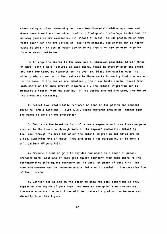
river being studied !generally at least two floodplain widths upstream end
downstream from the mined site locetionl. Photographic coverage is desired for
as many years as ere evai I able, but should at least include photos 20 or more
years epert for the evaluation of long-term changes. The photos can be repro
duced to obtain slides as described by Brice I 19711 or can be used in print
form as described below:
I. Enlarge the photos to the same scale, whenever possible. Select three
or more identifiable features on each photo. Piece en overlay over one photo
end mark the selected features on the overlay. Piece the overlay over the
other photolsl and match the features to these marks to verify that the scale
is the same. If the scales are identical, the river banks can be traced from
each photo on the same overlay !Figure A-1 1. The lateral migration can be
measured directly from the over ley. If the scales ere not the same, the follow
ing steps ere necessary.
2. Select two identifiable features on each of the photos end connect
these to forme baseline !Figure A-21. These features should be located near
the opposite ends of the photograph.
3. Subdivide the baseline into 10 or more segments end drew lines perpen
dicular to the baseline through each of the segment endpoints, extending
the I ine through the eree for which the lateral migration estimates are de
sired. Subdivide one of these I ines end drew lines perpendicular to form a
grid pattern !Figure A-31.
4. Prepare a similar grid to any desired scale on e sheet of paper.
Transfer bank locations at each grid square boundary from each photo to the
corresponding grid square boundary on the sheet of paper !Figure A-41. The
rows and columns can be numbered end/or lettered to assist in the coordination
of the transfer.
5. Connect the points on the paper to show the bank positions as they
appear on the photos !Figure A-51. The smeller the grid is on· the photos,
the more accurate the bank lines wi I I be. Lateral migration can be measured
directly from this figure.
85

p-Lake
1978
\_Bedroc~ CAll crop
Irregularly Shaped Grove of Trees--
Figure A-1. Schematic of overlay showing topographic features used as match points and bank I ines from 1948 and 1978 photographs.
Figure A-2 •. Schematic showing the selection of features to use as baseline endpoint for a portion of the study reach.
86
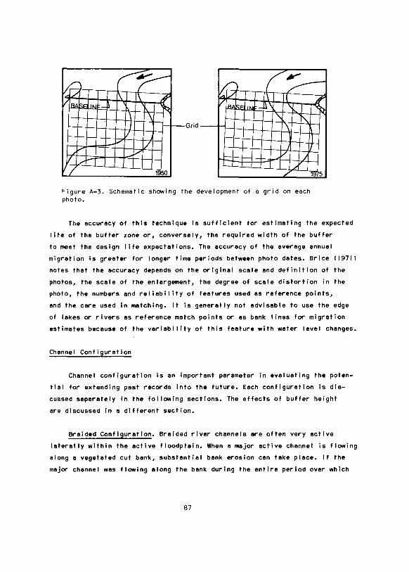
r ~r ~IL l\ 1\ 1' I LB.!! SEliN n ~
\ \ I 1- Grid
t2 (~ I\ l ; /LB.!! SF 1~1 :-ll \ ~
" ~ \
I v 1/
T /
l...,d 'I 1950
v .11 /1
/ m5
Figure A-3. Schematic showing the development of a grid on each photo.
The accuracy of this technique is sufficient for estimating the expected
life of the buffer zone or, conversely, the required width of the buffer
to meet the design life expectations. The accuracy of the average annual
migration is greater for longer time periods between photo dates. Brice I 1971 l
notes that the accuracy depends on the original scale and definition of the
photos, the scale of the enlargement, the degree of scale distortion in ·the
photo, the numbers and reliability of features used as reference points,
end the cere used in matching. It is generally not advisable to use the edge
of lakes or rivers as reference match points or as bank lines for migration
estimates because of the veriebi I ity of this feature with water level changes.
Channel Configuration
Channel configuration is en important parameter in evaluating the poten
tial for extending pest records into the future. Each configuration Is dis
cussed separately in the following sections. The effects of buffer height
ere discussed in a different section.
Braided Configuration. Braided river channels ere often very active
laterally within the active floodplain. When a major active channel Is flowing
along e vegetated cut bank, substantial bank erosion can take place. If the
major channel was flowing along the bank during the entire period over which
87
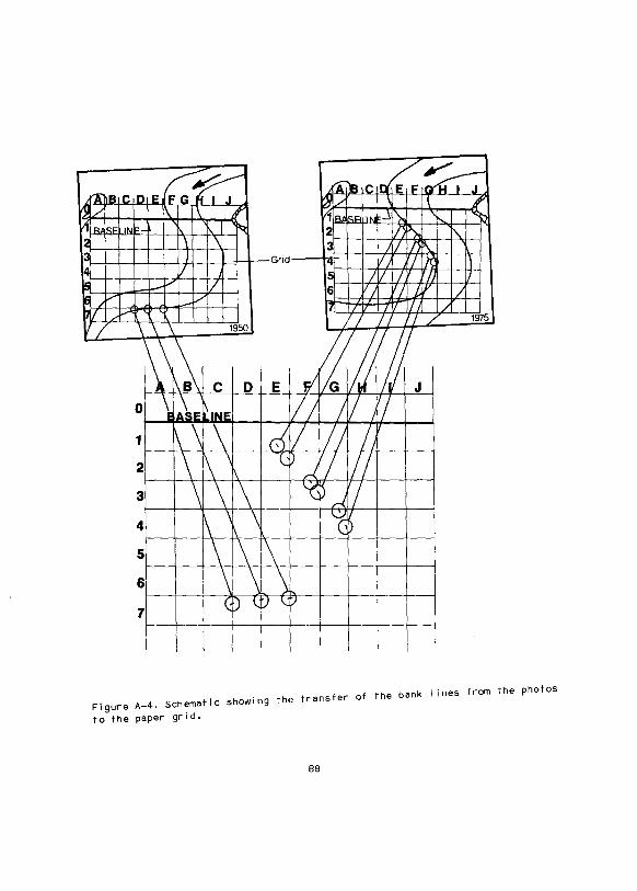
c~ /r
ahB1CrD1E FG~I J I'A.'Brr.1~ E,F,~
V4[L 1\ \ 7' Qiv \ /
~I RJk~ lr"lc. ~ 1le.tlsl"11r ~ f); "'<:
2 \ \ 2 II ~ "'
3 J 3 fl !I\
4 1/ Grid 1'1 v 'I IX rT
Is _.......... 7 IS / 1/ 7 rz 16 / v v 6 IT; 117 L'f' /
171/ / 17 f// /
llj \ 1950 I I /;_ 'l /' 1975
\ E ~g 1\B c D J
0 ~A\E INE 1/; ;f/ r; 1 \ \ r-{ 1/ 1/; ! 2 1\ \ -l D
~ 7 Ill 3 \ ~ ~r< r; 4 1\ \ \ GD 5 \ 6 \ \ 7
( D <.. :J \..[) -
Figure A-4. Schematic showing the transfer of the bank I ines from the photos
to the paper grid.
88

A B c H J
'V' I'~~ I I J 1 D~,l:'-'"r 1 =Kr 7, ~·x: DepOsition
Erosion-1 ~ I I 1 'Ill ' Y' 1 ..... -2 r · ~ I I
Figu~e A-5. Completed schematic showing bank I ines and zones of e~osion and deposition f~om
which ~ates of e~osion can be measu~ed.
.rosion
the historical mig~ation ~ates we~e estimated, that migration rate may be
projected into the future. Otherwise, different locations on the floodplains
should be selected for obtaining estimates. Any change in the alignment of the
channel should be accounted for, with erosion rates Increasing for increasing
angles of the channel to the bank. A factor of safety should be applied to the
result, its value depending on the confidence one has in the estimate for a
given system.
As a hypothetical example, consider the length of bank labeled A In
Figure A-6. The dashed line shows the channel as it appeared In 1950 and the
sol ld line represents the location of the 1975 river channel. Assume that the
lateral migration of bank A was measured to be 100m, or 4 m per year. Assume
it is desired to have a buffer lasting at least 8 years to protect a scraped
gravel removal area in the inactive floodplain. Projecting the past into
the future results in 4 m per year for 8 years, or 32m.
89

Figure A-6. Schematic of a river with a braided configuration with the 1950 and 1975 channel locations shown.
• The 1950 channel alignment was at a larger angle to the bank than the
1975 channel; thus it Is likely that the erosion rates were greater
than 4 m per year for the 1950 alignment and less than 4 m per year for
the 1975 alignment. The 32m can thus be reduced slightly, possibly to
28m. If intermediate photos (between 1950 and 1975) ere evai I able,
this figure can be substantiated by estimating the erosion rete for the
more recent time period. If the year to year activity of the active
channels is relatively low, it can be assumed that the potential for a
significant change in alignment is low, end e fairly low safety factor
can be used. In this case, e safety factor of 1.5 applied to .the 28m
value would result in a buffer width of 42 m.
• If the active channels ere known to change substantially every year,
the reduction for el ignment should not be appl led and a safety factor
90

of 2.0 or more could be used. This would result in e buffer width of 32
m x 2.0, or 64 m.
It is possible to find e braided configuration where the length of benk
defining the buffer is not adjacent to en active channel, e.g., area B in
Figure A-6. In this situation, the migration rate at area A can be applied to
area Band modified for various considerations. Assuming an B-year I ife is
desired, the starting width is 32 m. This width can probably be reduced, the
amount of reduction depending on the annual lateral activity level of the
active channels. Assume that the activity level is low. One might reduce the
number to 24m in that situation. However, if the active channel does shift,
it wi I I I ikely impinge on the bank at a relatively large angle, increasing
erosion potential. As a result, the width should be increased to 36m instead
of decreased to 24m. With relatively stable channels, the safety factor can
be about 1.5 to obtain a 54-m wide buffer.
Split Configuration. Rivers with split channel configurations are typ
ically much more laterally stable than braided rivers. Thus, a historical
record of erosion rates for e split river is fairly rei iable for projecting
future erosion rates. Channel alignment with respect to the buffer bank is an
important consideration, with larger erosion rates expected from channels with
larger angles to the bank. The factor of safety to apply to buffers on rivers
with split configurations mey be as low as 1.2; the factor of safety would
increase with increasing channel activity and with decreasing confidence in
the buffer width estimate. See discussions of meandering and braided config
urations for hypothetical examples of extending historical erosion rates.
Meandering Configuration. Rivers with meandering configurations typically
experience varying degrees of lateral migration, but the location end direc
tion of migration is fairly predictable. A historical record of erosion rates
for a meandering system can be used to predict future erosion rates with a
high degree of rei iabi I ity relative to previous configurations. Channel align
ment with respect to en eroding benk tends to remain constant. The factor of
safety to apply to the width of buffers on rivers with meandering configura-
91

tions may be as low as 1.2 with a good data base; higher values should be used
as uncertainty increases In estimating the erosion rate.
The pattern of a meandering river and the expected zones of erosion are
i I lustrated in Figure A-7. Most meandering rivers deviate to some degree from
I
I I
II I \
I ',,_____ Er, - .... os;o, --- .....
' ' ' \ Meander Belt Width \
Figure A-7. Schematic of a meandering river showing the expected zones of erosion as the river meanders migrate down the val ley.
92

this pattern, but the besic principles ere the seme. Meandering rivers exhibit
e general tendency to migretq downvel ley by eroding the cut benk on the out
side of e bend from e point roughly midwey through the bend end extending
generel ly to the beginning of the inside of the next bend downstream. The
greduel downvel ley progression of the bends usuel ly remains within e zone
eel led the meander belt drewn neer the outside of eech meander. The width of
the meander belt is usuel ly constant for regul.er meander patterns. Irregular
meander patterns do not necessarily meintein e constant meander belt width,
but the erosion et the outside of bends is typical. The difference between e
regular meander pattern end en irregular meander pattern end the expected
zones of erosion essocieted with eech is shown in Figure A-8. It is epperent
Regular Meander Pattern Irregular Meander Pattern I
Figure A-8. Schematics of regular and irregular meander patterns and typical erosion zones.
93
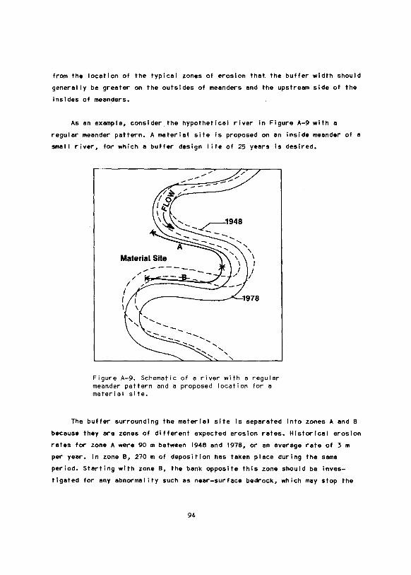
from the location of the typical zones of erosion that. the buffer width should
generally be greater on the outsides of meanders and the upstream side of the
insides of meanders.
As an example, consider the hypothetical river in Figure A-9 with a
regular meander pattern. A material site is proposed on an inside meander of a
smal I river, for which a buffer design I ife of 25 years is desired.
Figure A-9. Schematic of a river with a regular meander pattern and a proposed location for a material site.
The buffer surrounding the material site is separated into zones A and B
because they are zones of different expected erosion rates. Historical erosion
rates for zone A were 90 m between 1948 and 1978, or an average rate of 3 m
per year. In zone B, 270m of deposition has taken place during the same
period. Starting with zone B, the bank opposite this zone should be inves
tigated for any abnormality such as near-surface bedrock, which may stop the
94

erosion of this bank. If there is such an abnormality, the buffer width should
be increased from the standard minimum buffer width for the downstream end of
the site given in Section V A 3b. In this example, assume no abnormality
exists; use a standard minimum buffer width increased by 25 percent t.o account
for the increased design life 125 years instead of 20 years! to derive a 19m
width in zone B. For zone A, an annual migration of 3m per year over 25 years
would prescribe a 75-m wide buffer. No change in the average erosion rete is
expected from, for example, a meander cutoff developing upstream, end the
historical period is longer than the design life, thus, the user can feel
confident with the prediction. A safety factor of 1.2 can be used resulting in
a recommended buffer width of 90 m.
Sinuous Configuration. A river with a sinuous channel configuration is
expected to behave in a simi tar manner to that of the meandering rivers with a
few exceptions: erosion rates ere often less in sinuous rivers then in mean
dering rivers; and the erosion zone may extend farther upstream on the outside
of a sinuous river meander !Figure A-101. Otherwise, simi tar procedures can be
used to estimate the recommended buffer zones. Safety factors as low as 1.2
can be applied to the buffers in zones of erosion on these relatively stable
rivers. See the discussion on meandering rivers for a hypothetical example of
estimating buffer sizes.
Straight Configuration. A river with a straight configuration wi I I I ikely
have a simi ler erosion pattern to that of sl~uous rivers, only less pro
nounced. Straight rivers typically exhibit a sinuous pattern in their thalweg
with the inside meanders being formed by alternate bars or side channel bars.
Thus, what little bank erosion takes place in a straight river would occur
opposite and slightly downstream from these gravel bars, which may be sub
merged under most flow conditions !Figure A-1 II. Safety factors as low as 1.0
may be appropriate on straight rivers. The reason for the straight el ignment
should be considered before evaluating the buffer requirements. For example,
if the straight reach resulted from meander cutoffs, a much larger buffer
would be required then if the straight reach is due to erosion resistant
banks.
95
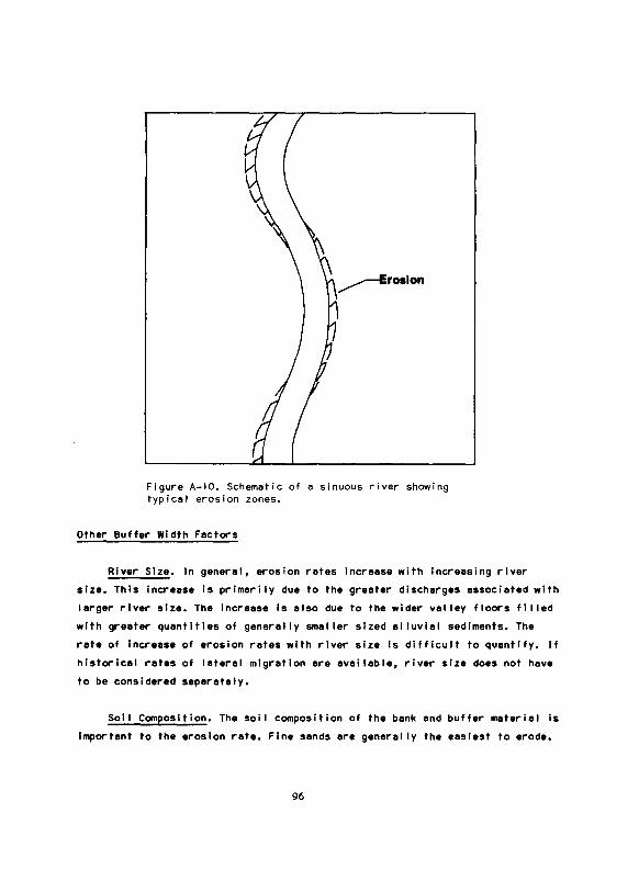
Figure A-10. Schematic of a sinuous river showing typical erosion zones.
Other Buffer Width Factors
River Size. In general, erosion rates Increase with Increasing river
size. This Increase is prlmeri ly due to the greeter discharges associated with
larger river size. The Increase is also due to the wider vel ley floors fl I led
with greeter quantities of generally smeller sized el luvlel sediments. The
rete of Increase of erosion rates with river size Is difficult to quantify. If
historical rates of lateral migration ere evei I able, river size does not have
to be considered separately.
Sol I Composition. The soil composition of the bank end buffer materiel Is
Important to the erosion rete. Fine sends ere generally the easiest to erode.
96
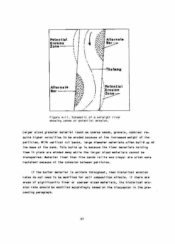
I I
I I
Potential f Erosjon 1 Zone----;-
' I I I I \
'!\ 'oaa, ~000\
I
i1 I I
\ I \
\ Thalwe.g \ I
I I I '~otential ~~~-r·~ :o0o~ \Erosion Alte ·~:· .. ,
o o 0 ol Bar g:·g~, ~ ' ' 0 0 .,
I 'ooo~
/ )1 I ~· I
~ , ,
Figure A-1 I. Schematic of a straight river showing zones of potential erosion.
Larger sized granular material <such as coarse sands, gravels, cobbles! re
quire higher velocities to be eroded because of the increased weight of the
particles. With vertical cut banks, large diameter materials often build up at
the base of the bank. This build up is because the finer materials holding
them in place are eroded away while the larger sized materials cannot be
transported. Materiel finer then fine sends lsi Its end cleysl ere often more
resistent because of the cohesion between particles.
If the buffer materiel is uniform throughout, then historical erosion
rates do not need to be modified for soil composition effects. If there ere
areas of significantly finer or coarser sized materials, the historical ero
sion rete should be modified accordingly based on the discussion In the pre
ceeding paragraph.
97

Vegetative Cover. Vegetation with deep root structures provides a resis
tance to bank erosion. Dense ground cover on the buffer provides an increase
in the roughness of the buffer, causing a decrease in the velocity of flow
over the buffer. This, in turn, reduces the potential for erosion of the
buffer surface and the development of a channel through the buffer. This is a
primary reason why a buffer should not be disturbed.
When extending historical erosion rates, the vegetative pattern should
be considered. No compensation for vegetation is required if the vegetation is
comparable between the buffer and the area that eroded during the period of
historical erosion. If the vegetation type or density changes within the
buffer, or between the buffer and the area of historical erosion, then the
historical rate of erosion should be modified according to the type of change
and the discussion in the preceeding paragraph.
Permafrost Banks. The erosion of permafrost banks is a more complicated
process then unfrozen bank erosion. Varf~us investigators have studied the
process; some have concluded that permafrost increases bank erosion, others
have decided that permafrost decreases bank erosion. Scott I 197Bl reviewed
previous investigations and added his own investigation of five rivers in
arctic Alaska. He concluded that the net effect of permafrost is to create
greater channel stability than is found in rivers of similar size in nonperma
frost environments. However, banks which are ice-rich wi I I I ikely have less
stabi I ity and higher erosion rates than other permafrost or nonpermafrost
banks.
When using past records to predict future conditions, the thermal con
dition of the banks should be considered. Past thermal conditions of the
banks are generally not known, consequently, it must be assumed that they were
similar to the current condition. If the banks are ice-rich, the safety factor
applied to the buffer width should be larger.
Channel Aufeis. Aufeis development in the active channel of a river can
cause a larger percentage of the snowmelt runoff to flow across the buffer
than otherwise would be expected. Doyle and Childers I 19761 show a photograph
98
of this occurring at the Prospect Creek material site near the Trans-Alaska
Pipe! ine. This increased flow can cause erosion of the surface of the buffer,
especially any disturbed area. It can also cause scour or headcutting in the
material site because of the larger-than-design flows during breakup. The
safety factor applied to buffer width should be increased if channel eufeis is
known to develop at the site.
BUFFER HEIGHT
Buffer height and buffer width are interrelated to a certain degree.
If the buffer is high enough to keep alI but the largest of floods out of
the material site, only bank erosion needs to be considered in buffer design.
This may be the situation for many material sites located on terraces. If the
buffer is low and is flooded frequently by larger flows, erosion of the sur
face of the buffer, headward erosion of the upstream face of the material
site, and scour within the site must be considered in the buffer design. The
height of natural buffers is fixed at the level provided by nature. Design
options include increasing buffer width to account for low height, bui I ding up
the buffer height by adding a dike on the river side, or bui !ding a completely
separate buffer structure. These options are discussed in more detai I in a
subsequent paragraph.
To evaluate the frequency of flooding, hydrologic and hydraulic analyses
must be carried out. The detai Is of these analyses are too complex to explain
here, but appropriate references are given to allow the user to study the
subject further.
• A hydraulic analysis is required to evaluate what discharge wi I I ini
tiate overtopping of the buffer. Cross sections of the river, extending
up to the level of the buffer on both banks, are necessary for this
analysis. It is preferable to have five or more cross sections through
the reach of river adjacent to the buffer. The Manning equation or,
perferably, a backwater program, should be used to calculate the dis
charge corresponding to the stage that would overtop the buffer. Discus
sions of these analyses are provided in most open-channel hydraulics
99

textbooks !Chow 19591, and in other references !Bovee and Mi lhous 1978;
u. S. Army Corps of Engineers 19761.
• A flood frequency analysis provides an estimate of the recurrence
interval or probabi I ity of exceedance of the discharge which just
overtops the buffer. Detailed discussion of flood frequency analyses
are included in most hydrology textbooks, U. S. Water Resources Counci I
I 19771, and Lamke I 19791. Lamke I 19791 provides equations for deter
mining flood discharges for rivers in Alaska for the following recur
rence intervals and corresponding exceedance probabi I ities:
Recurrence interval
I years I
1.25
2
5
10
25
50
100
Exceedance probabi I ity
1%1
80
50
20
10
4
2
With the discharge and its frequency of occurrence known, the probabi I ity
of that flood occurring over the design I ife of the buffer is needed. Table
A-I below provides the probabi I ity of occurrence of a flood of a specified
recurrence interval during a specified buffer design I ife.
100
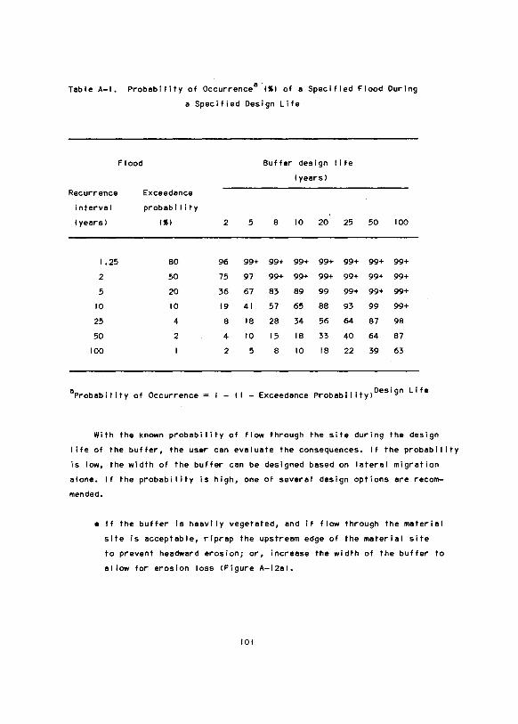
Table A-1. Probability of Occurrencea .1%1 of a Specified Flood During
a Specified Design Life
Flood Buffer design life
I years I
Recurrence Exceedance
interval probab iIi ty
I years I 1%1 2 5 B 10 20 25 50 100
1.25 BO 96 99+ 99+ 99+ 99+ 99+ 99+ 99+
2 50 75 97 99+ 99+ 99+ 99+ 99+ 99+
5 20 36 67 63 69 99 99+ 99+ 99+
10 10 19 41 57 65 BB 93 99 99+
25 4 B IB 26 34 56 64 67 98
50 2 4 10 15 IB 33 40 64 67
100 I 2 5 B 10 IB 22 39 63
8 Probability of Occurrence I - (I - Exceedance Probabil ityiDesign Life
With the known probability of flow through the site during the design
I ife of the buffer, the user can evaluate the consequences. If the probability
is low, the width of the buffer can be designed based on lateral migration
alone. If the probability is high, one of several design options are recom
mended.
• If the buffer is heavily vegetated, and if flow through the material
site is acceptable, riprap the upstream edge of the material site
to prevent headward erosion; or, increase the width of the buffer to
allow for erosion loss !Figure A-12al.
101
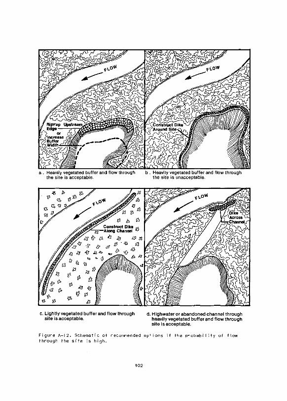
a . Heavily vegetated buffer and flow through the site is acceptable.
c. Lightly vegetated buffer and flow through site is acceptable.
b . Heavily vegetated buffer and flow through the site is unacceptable.
d. Highwater or abandoned channel through heavily vegetated buffer and flow through site is acceptable.
Figure A-12. Schematic of recommended options if the probabi I ity of flow through the site is high.
102

• If the buffer Is heevi ly vegetated, end flow through the site is unac
ceptable, construct e dike surrounding the materiel site designed
for e flood with en acceptably low probebil lty of occurrence !Figure
A-12bl.
• If the. buffer Is I ightly vegetated, build a dike along the river side
of the buffer designed for e flood with en acceptably low probebl llty
of occurrence !Figure A-12cl.
• If the buffer contains e high-water or abandoned channel, build e
dike along the river side of the buffer to keep flow out of the chan
nel; the dike should be designed fore flood with en acceptably low
probebi I ity of occurrence (Figure A-12dl.
As an example of buffer height design, consider the materiel site loca
tion shown in Figure A-13. The buffer width has been estimated by historical
Cross Section 5 1 1 .. ··_.,:I
Cross Section 6--
Pit Material Site
Figure A-13. Schematic of an example of buffer height design.
103
erosion techniques. Cross sections are surveyed as shown ltwo additional
cross sections were collected further downstream). A backwater analysis was
run to find that discharges of 103 m3ts and 89 m3ts overflowed the buffer at
Cross Sections 3 and 7, respectively. A flood frequency analysis indicated
that these discharges had recurrence intervals of 35 and 25 years. The design
I ife of the buffer is 25 years. Thus, from Table A-1, at Cross Section 7 there
is a 64 percent chance of getting flow into the downstream end of the material
site within the 25-year I ife. This chance is acceptable to the user because
the flow would primarily be backwater and would have relatively low erosion
potential. At Cross Section 3 the upstream buffer has a 50 to 60 percent
chance of overtopping the buffer. The user finds this to be unacceptable, but
since there is a relatively smal I chance of substantial flow entering the pit
from the upstream side, he recommends riprapping the upstream bank of the pit.
REFERENCES
Bovee, K. D., and R. T. Mi lhous. 1978. Hydraulic Simulation in lnstream Flow
Studies: Theory and Techniques. lnstream Flow Information Paper No.
5. Cooperative lnstream Flow Service Group. Fish and Wildlife Service.
Fort Col I ins, Colorado. 125 pp.
Brice, J. 1971. Measurement of Lateral Erosion at Proposed River Crossing
Sites of the Alaska Pipeline. U.S. Geological Survey. Water Resources
Division. Alaska District. 39 pp.
Chow, V. T. 1959. Open-Channel Hydraulics. McGraw-Hi I I Book Company, New
York. 680 pp.
Doyle, P. F., and J. M. Childers. 1976. Channel Erosion Surveys Along TAPS
Route, Alaska, 1976. Open-File Report-77-170 !Basic Datal. U.S. Geolog
ical Survey. Anchorage, Alaska. 90 pp.
Lamke, R. D. 1979. Flood Characteristics of Alaskan Streams. Water Resources
Investigations 78-129. U.S. Geological Survey. Anchorage, Alaska. 61 pp.
104

Scott, K. M. 1978. Effects of Permafrost on Stream Channel Behavior in
Arctic Alaska. Professional Paper 1068. U.S. Geological Survey. U.S.
Government Printing Office, Washington. 19 pp.
U. S. Army Corps of Engineers. 1976. HEC-2 Water Surface Profiles: Users
Manual. Computer Program 723-X6-L202A. The Hydrologic Engineering Center.
Davis, California. 17 pp. +Appendix.
u. S. Water Resources Counci I. 1977. Guidelines for Determining Flood Flow
Frequency. Bullet in No. 17A of the Hydrology Committee. Washington.
26 pp. + 14 Appendix.
105


APPENDIX B
FIELD INSPECTION: DESIRABLE DATA,
PROCEDURES, AND EQUIPMENT
APPLICANT SITE PLANNING FIELD INSPECTION
As part of the site planning process the applicant is recommended to
visit the proposed site or alternate sites, or both, during the open-water
season to gather the following information:
A. Technical data to substantiate aerial photographic interpretation
I e.g., sufficient quantity and quality of material, and percent
fines!.
B. General site specific biological data regarding the presence of areas
or species of special concern that may be directly influenced should
site development occur.
C. Site specific hydraulic data relevant to site planning and agency
review le.g., discharge, stage, and cross sections).
D. Ground photographs of site physical and biological characteristics
which wi I I be used in support of work plan development and submittal
to appropriate agencies.
E. If a snow-covered site wi I I be opened, alI work area locations should
be surveyed during the open-water site visit. This survey should be
from reference locations that can be located during site opening.
Boundaries, such as those of active channels, buffer locations, vege
tated areas, and gravel deposits, can then be accurately relocated
during site preparation. This wi I I reduce the potential for damage to
areas that should not be disturbed.
107 -
F. If winter active-channel mining is contemplated, an additional site
visit during winter should be conducted. Its purpose is to determine
the presence of water at or below the proposed site.
Field Approach
Material Avai labi I ity. A variety of techniques are avai I able to evaluate
grandular materiels present at a site. These include borings, test pits, and
resistivity measurements.
Biological Evaluation. The entire site should be walked (during which
time ground photos should be obtained) to subjectively assess the overal I fish
and wildlife habitat quality in sufficient detai I to make Decisions I through
4 in Section I B. It may be appropriate to make this a combined appl icent
agency site visit.
Hydraulic Date. Cross Sections: Cross sections of the river channellsl
end floodplain should be surveyed to provide input to the hydreul ic analysis
and the level to which excavation can extend. The number, location, and length
of the cross sections should be based on the following criteria !Figure B-1 J:
• There should generally be at least five cross sections; three or more
would generally be necessary to describe the site end one or more would
be required upstream and downstream from the site.
• Cross sections through the site should be located at the upstream and
downstream ends as wei I as one or more in between to define the extent
of mining.
• In addition to the locations necessary to define the site, cross sec
tions should be located at each significant change in floodplain width.
• The upstream and downstream cross sections should be located at least
two active channel-top widths from the upper and lower I imits of the
materiel sites end associated buffers.
108
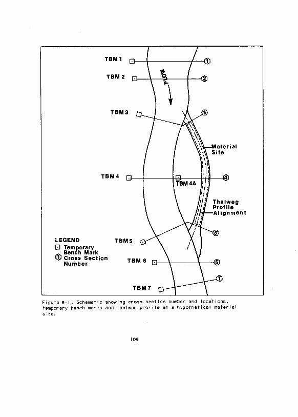
TBM 1
TBM2
TBM3
TBM4
LEGEND TBMS 0 Temporary
Bench Mark Ill Cross Section
Number
Figure B-1. Schematic showing cross section number and loca.tions, temporary bench marks and thalweg profile at a hypothetical material site.
109
• The length of the cross sections should include the entire active
floodplain width and should continue to an elevation on both ends
equivalent to at least the highest point in the material site or the
buffer, whichever is greater.
• Cross sections should be aligned perpendicular to the direction of flow
during flood events.
• The distances between and direction of the cross sections should also
be surveyed.
The surveys should be performed using standard surveying techniques. A descrip
tion of these techniques and the desired accuracy is given in Bovee and
M i I hous ( 197B I •
Temporary Bench Marks: Temporary bench marks !TBMsl should be placed at
one end of each of the cross sections and one near the active channel where
the discharge measurements are taken !Figure B-1 l. The TBM elevations should
be tied into a common datum !often arbitrary datum at the upstream cross
section) as described in Bovee and Mi lhous ( 19781.
Stage and Discharge: The stage !water surface elevation) should be re
corded at the time the discharge measurements are taken. Discharge measure
ments should not be taken while the discharge is rapidly changing. Discharge
measurements should be taken at a cross section in a relatively uniform chan
nel reach; that is, the water surface slope and bottom slope should be similar
and the depth, area, velocity, and discharge should not change significantly
through the reach. Discharge measurements are taken by measuring the total
depth and the velocity at specified depths at 25 to 30 stations across the
channel. The station (distance from a TBMl should also be recorded. Velocity
measurements should be taken at the following recommended depths below the
water surface relative to the total depth !dl:
- 0.2d, 0.6d, and O.Bd is most preferred
110
- 0.2d and O.Bd is next most pr.eferred
- 0.6d is recommended only if the depth ldl is less than 0.75 m
If the discharge is changing rapidly and the measurements must be taken at
that time, the 0.6d method should be used to complete the measurements faster.
Additional detai Is on discharge measurements can be found in Bovee and Mi lhous
I 19781 or Buchanan and Somers I 19691.
Bed Material Size Distribution: The size distribution of the surface
layer of bed material is required for evaluating the hydraulic roughness of
the channel and floodplain. These data are obtained by an analysis of photo
graphs using a grid-by-number technique as described by Kel lerhals and Bray
I 1971 l or Adams I 19791. The photographs should be taken, vertically downward,
of at least a I m square area of undisturbed surface layer gravels. A scale
should be included in the photograph.
Thalweg Profile: A thalweg profile should be surveyed of the channel bed
at those sites where the material site is being proposed on a gravel bar
adjacent to the channel or in the channel itself !Figure B-1 l. These data are
needed in the determination of the maximum depth to which gravel can be ex
tracted. The profile should extend at least five channel widths beyond the
ends of the mined site.
Photographs. Photographs should be taken to show the main habitat fea
tures of the river reach being studied !e.g., riffles, runs, pools, islands,
gravel bars, riparian shrub thickets, mud flats, backwater areas, incised and
undercut banks!. If possible, photographs should be taken from an elevated
vantage point, such as a high bank. A sequence covering the entire reach of
stream is desirable. A record should be made of each photograph, including
date, time, location, direction of photograph, sequence, and main features
being photographed. If the visit is a follow-up to a previous field visit,
photographs identical to those obtained previously should be taken, as wei I as
those showing new features. If a winter visit occurs, photograph aufeis and
river ice characteristics.
Ill
AGENCY FIELD INSPECTION
The initial agency field inspection is recommended to verify the data
supplied by the applicant and to gather additional environmental data at
the site to identify the significant biological habitats. With this informa
tion, any appropriate work plan that minimize environmental impacts can be
recommended. The field inspection should evaluate the overal I habitat quality
and include observations on site-specific parameters including:
• General configuration of the river.
• Channel top width !size of river).
• Stage and discharge.
• Mean velocity.
• Bank and instream cover.
• Substrate.
• Pool:riffle ratio.
• Presence of sensitive areas I i.e., spawning and overwintering areas).
• Dominant terrestrial habitats.
Desirable field inspection equipment for this site visit includes:
• Devices to measure water depth and top width.
• Device to measure water velocity.
• Data sheets of field book for recording field observations.
• 35 mm camera with color slide or print film.
• Dip net.
• Binoculars.
During the initial field visit a site sketch should be prepared perferably
using a copy of the aerial photo supplied with the work plan. This sketch
should identify major aquatic and terrestrial habitat locations and configura
tions in relation to the boundaries and configuration of the work area, and
locations of special features such as settling basins, stockpiles, access
points, and others.
112
Subsequent agency visits (during site operation end site closure) should
measure the seme parameters and document habitat alterations.
Field Techniques
Observations. Record and numerate alI fish end wildlife encountered in
each habitat type.
Stream Velocity. Stream velocity can be estimated by placing a biodegrad
able object with e density slightly less then that of water (such as an orange
or lemonl, in the river end recording the time required to travel between two
measured points. Express the me~surement in feet or meters per second.
Bank and lnstream Cover. Bank and instream cover cen be expressed as
percent of total cover and percent by each category. Categories for which
avai I able habitat should be assessed include:
• Banks- undercut bank, overhanging bank vegetation, end near-surface
!submerged and emergent) bank vegetation.
• lnstream- boulders, .logs, large debris, and other velocity bar
riers.
• Depth- water depth acting as cover such as deep pools end runs.
Substrate. Estimate the percent of substrate composed of the different
particle sizes according to the modified Wentworth scale supplied in Appendix
H. Separate by pool and riffle.
Photogrepns. Photographs should be obtained to show the main habitat
features of the river reach being studied le.g., riffles, runs, pools,
islands, gravel bars, riparian shrub thickets, mud flats, backwater areas,
incised and undercut banksl. If possible, photographs should be collected from
en elevated ventage point, sucn es a high bank. A sequence catering the entire
reach of stream is desirable. A record should be made of each photograph,
113

including d~te, time, loc~tion, direction of photogr~ph, sequence, end mein
features. Photographs identical to those obtained previously should be taken,
as wei I es those showing new features if the visit is a follow-up to a pre
vious field visit.
Riparian Zones. These arees provide primary feeding, nesting, end cover
hebitet for pesserines and smel I ·and medium sized mammals. During winter
they also provide primary overwintering habitat for moose and ptarmigan.
Areas that consist of advanced or mature sere I stages, generally have wei!
developed ground cover, shrub layer or overstory cover, or both, I in Northern
and Southern Interior regions) thet provide desirable hebitet. Sites that
contain riperien zones with high diversity of cover types !herbaceous marsh,
mature shrub "thickets, mixed shrub thicket-early overstory forest and over
story forestl may be considered more desirable than sites containing riparian
zones of homogeneous cover types. Watch for indicators of past activity
levels: old passerine nests, smel I memmel runways and burrows, red squirrel
feeding posts, moose browse, and moose and ptarmigan droppings in over
wintering areas.
Water Bird Habitat. Feeding, nesting, and cover habitat for waterfowl,
shorebirds, terns, and gul Is should also be assessed. Determine evei labi I ity
of, end if possible uti I ization level of:
• Backwater areas, mud flats, and I ittoral areas es feeding habitat by
shorebirds, terns, and waterfowl.
• Pools and side-channels as feeding habitat by terns, gul Is, and water
fowl.
• Open and sparsely vegetated gravel bars as nesting habitat by gul Is,
terns, and shorebirds !most frequently, semip·almated plovers, ruddy
turnstones, spotted sandpipers).
• Herbaceous riparian zones as nesting habitat by waterfowl and shore
birds.
114

Sites with a diversity of water bird habitats are more desirable than
sites with only one or two types present.
REFERENCES
Adams, J. 1979. Gravel size analysis from photographs, pp. 1247-1255. ~
ASCE, J. Hydraulics Div. Proc. Paper 14908, Vol. 105, No. HYIO, October.
Bovee, K. D., and R. T. Mi lhous. 1978. Hydraulic Simulation in lnstream Flow
Studies: Theory and Techniques. lnstream Flow Information Paper No. 5.
Cooperative lnstream Flow Service Group, Fish and Wildlife Service, Fort
Col I ins, Colorado. 125 pp.
Buchanan, T. J., and W. P. Somers. 1969. Discharge Measurements at Gaging
Stations, 65 pp. ~Techniques of Water-Resources Investigations of the
U.S. Geological Survey, Book 3, Applications of Hydraulics. U. S. Govern
ment Printing Office, Washington, D. C.
Kellerhals, R., and D. I. Bray. 1971. Sampling procedures for coarse fluvial
sediments, pp. 1165-1180. ~ ASCE, J. Hydraulics Div. Proc. Paper 8279,
Vol. 97, No. HY8, August.
I 15

INTRODUCTION
APPENDIX C
RIVER-TRAINING STRU~TURES AND
BANK PROTECTION DEVICES
River-training structures and bank protection devices may be required
during gravel removal operations or site closure, or both. Their purposes can
include protection of the site from flow during operation or after closure
and reduction of the potential for downstream siltation. River-training
structures also may be used to protect the bank of e buffer from excessive
erosion. River-training structures end bank protection devices generally
should not be used unless absolutely necessary because they usually disrupt
natural river processes, often resulting in scour end erosion elsewhere in
the system. In addition, bank protection devices can alter banks end their
adjacent riparian zones.
Revetments constitute· the major group bank protection devices. River
training structures in gravel removal operations primerly consist of dikes;
other types of these structures include retards, guide banks, spurs, end
jetties. Several publications are avai I able that discuss the design of such
structures; these include California Division of Highways I 19601; Kereki et
al. I 19741; Nei I I I 19731; U.S. Army Corps of Engineers I 19701 and Winkley
119711. The following paragraphs discuss briefly dikes and revetments.
DIKES
Dikes are long embankments used to control the overflow of water into
the material site. Dikes may be constructed along an active channel or across
a high-water channel, or both. Dikes may also be used to block active side
channels in those cases where the bed is to be scraped. For these purposes,
the dikes should be impermeable, high enough to prevent overtopping, and
protected from erosion. Impermeable dikes are often constructed of stone or
earth, or both.
117
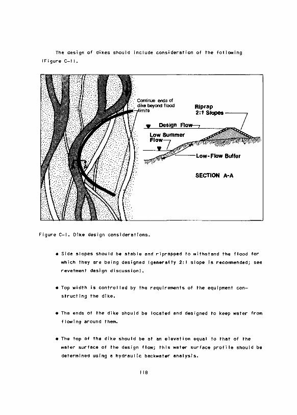
The design of dikes should include consideration of the following
<Figure C-1 l.
· Continue ends of · dike beyond flood Rip rap
2:1 Slopes---,
SECTION A·A
Figure C-1. Dike design considerations.
• Side slopes should be stable and riprapped to withstand the flood for
which they are being designed <generally 2: I slope is recommended; see
revetment design discussion!.
• Top width is control led by the requirements of the equipment con
structing the dike.
• The ends of the dike should be located and designed to keep water from
flowing around them.
• The top of the dike should be at an eievation equal to that of the
water surface of the design flow; this water surface profile should be
determined using a hydraulic backwater analysis.
118

• Dikes should be bul It beyond the limits of the low-flow buffer.
BANK PROTECTION BY REVETMENTS
A revetment is e leyer of erosion resistent materiel placed on a benk
or embankment to ermor against erosion. Methods end materiels for revetments
other then riprep ere evai I able but ere not discussed here because they
generally ere unacceptable for environmental reasons.
~
The most common form of revetment is riprep, a layer of rock which
may be dumped, hand-placed, or grouted. Dumped rock riprep is most commonly
used, although grouted rock riprep may be applicable if the evel leble ma
teriel is not lerge enough to meet the requirements of dumped riprap. Rock
filled wire baskets lgebionsl may elso be used when evei I able materiels ere
of insufficient size to meet dumped riprep requirements. There ere several
factors important in the design of dumped rock riprep; these include:
• Shape, size, end gradation of the rock.
• Density and durability of the rock.
• Velocity end depth of flow near the rock.
• Steepness of the slope being protected.
• Thickness of the riprap layer.
• Fi Iter blanket presence end design.
• End and toe protection.
These factors ere discussed briefly in the following sections.
Shape, Size, end Gradation. The shape, size, end gradation of the rock
riprep ere the primary properties in resisting erosion. The shape should be
angular to provide an interlocking of the rocks. Large rock is more erosion
resistent then smel I rock. Selection of the proper rock size is a complex
function of flow characteristics end slope of the embankment being protected.
Kereki et al. 119741 present a method for estimating rock size. Nei II 119731
119

presents e greph to use es e guide in selecting riprep size (Figure C-21.
7
~ , ,.
/" I.-' 6
~ , ..
If/ ~
,... " "'.; /
,.,.. 5
," ,. ,/ v: ~ .... ...
/ >" / / 0 ...... 4
~/ ~ / ..
~ ,
1/ ," ti ~ ~-
2 ~ ~" ,, kJ
1 L'
0 0 100 300 500 700 900 1100
EOUIVALANT SPHERICAL DIAMETER OF STONE (mm)
CURVE
0calif. Hgws .
SPECIFIED STONE SIZE %FINER
@Bur. Public Ads.
®Bur. of Reclarnn .
0eorps of Engrs.
@Recommended Curve to~ a Guide (Neill,19731
L:::J1 2
D33
Dso
BANK SLOPE
2c1
not given
not given
horizontal to 2: 1
Assumed stone spec1fic grav1ty = 2. 65
Figure C-2. Graph of riprap size vs. local flow velocity (modified from N'eill 19731.
It should be used with ceution beceuse not elI espects ere incorporeted.
Wei 1-greded meteriel improves the interlocking of the rock end reduces spaces
between rocks. A recommended gredetion is shown in Figure C-3.
Density end Durebi I ity. The rock used for riprep should be herd, dense,
end durable to withstand cycles of wetting end drying, end freezing end
thawing. These cycles cen ceuse cracking of the rock, resulting In reduction
of size end erosion resistance. Density end durebil lty ere generally deter
mined by leboretory tests.
120
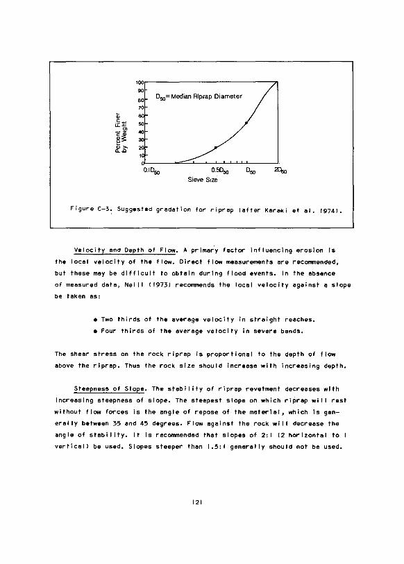
100[-------------------------------90! eoi 70
D50= Median Riprap Diameter
Q; eo .s:u..c 50 "E ·~ 40 ~~
&:b
0.1050 0.5050
Sieve S1ze
050 2Dso
Figure C-3: Suggested gredetion for riprep lefter Kereki et el. 19741.
Velocity end Depth of Flow. A primery factor influencing erosion Is
the local velocity of the flow. Direct flow measurements ere recommended,
but these mey be difficult to obtain during flood events. In the absence
of measured deta, Nei I I ( 19731 recommends the locel velocity against a slope
be teken as:
• Two thirds of the average velocity in straight reaches.
• Four thirds of the everege velocity in severe bends.
The sheer stress on the rock riprap is proportional to the depth of flow
ebove the riprep. Thus the rock size should increase with increasing depth.
Steepness of Slope. The stebi I ity of riprep revetment decreases with
increasing steepness of slope. The steepest slope on which riprep wit I rest
without flow forces is the engle of repose of the materiel, which is gen
erally between 35 end 45 degrees. Flow egeinst the rock wit I decrease the
angle of stebil ity. It is recommended that slopes of 2: I (2 horizontal to
vertical! be used. Slopes steeper than 1.5: I generally should not be used.
121

Thickness of Riprap. The ihickness of the riprap ~hould be sufficient
to provide the desired protection of the slope. The minimum thickness should
be equal to the longest dimension of the largest rock or be 50 percent larger
than the median rock size, whichever is larger. This minimum thickness should
be increased by 50 percent if:
• Wave action is possible.
• Gradation is not as recommended.
• Riprap is to be placed in flowing water.
• A fi Iter is not used when recommended.
Fi Iter Blankets. A fi Iter blanket may be recommended for placement
beneath the rock riprap layer to prevent the loss of bank material through
the voids in the riprap. If the material washes out, cavities wi I I form
beneath the riprap and failure of the riprap revetment can occur. The require
ments for a fi Iter depend on the size and gradation of the bank material and
on the voids in the riprap layer. If the compos it ion of the bank material is
such that it is eesi ly eroded, a fi Iter layer is generally recommended.
Poor riprap gradation is also a reason to recommend a fi Iter. Filters may
be wei 1-graded gravel or a synthetic fi Iter cloth.
Gravel filters should use gravels ranging from about 5 mm to 90 mm
I Karak i et a I. 1974 I. F i Iter thickness shou I d be no I ess than 0. 15 m; f i Iter
thickness equal to half the riprap thickness is recommended. More than one
layer, of different gradation and median size, should be considered if there
is a very large difference in size between the bank material and the riprap
rock. Recommended guide I ines for gradation of the fi Iter ere given by Karaki
et al. I 19741; they are summarized in relations below.
These relations should be applied to each layer in turn, starting with
the bank material as the fine material and using the needed fi Iter material
as the coarse. The first fi Iter selected then becomes the fine material for
the next fi Iter layer computation. After determining the size and gradation
of each fi Iter, these relations should be used with the last selected fi Iter
122

as the fine materiel and the riprep as the coarse materiel. If the results
are within the indicated limits, an additional fi Iter layer is not needed.
• o50
(coarse)
< 40 o
50 lfine)
• 5 o15 !coarse) < 40
o15 !fine)
• o15 !coarse) < 5
o85 !fine)
Where o50 is median diameter, o15 is the diameter particle of which 15 per
cent of the materiel is finer, and o85 is the diameter particle of which
85 percent of the material is finer. An example of fi Iter gradation design
is given in Figure C-4.
Fi Iter cloths have been used with success for more then a decade. They
can support large riprap material with no damage to the cloth. A disadvan
tage of fi Iter cloths is that the riprap must be placed with care to prevent
damage to the cloth.
End and Toe Protection. The ends of the riprep revetment along the
channel may be subject to erosion. The erosion could remove material from
behind the riprap and cause failure of the riprap. Extending the riprap
revetment to areas not having erosive velocities is a recommended end protec
tion !Figure C-5a). If this is not possible, the thickness of the riprep
layer should be increased to twice that otherwise needed. This extra thick
ness should be placed in a recess cut into the bank to maintain a uniform
riprap face !Figure C-5b).
123
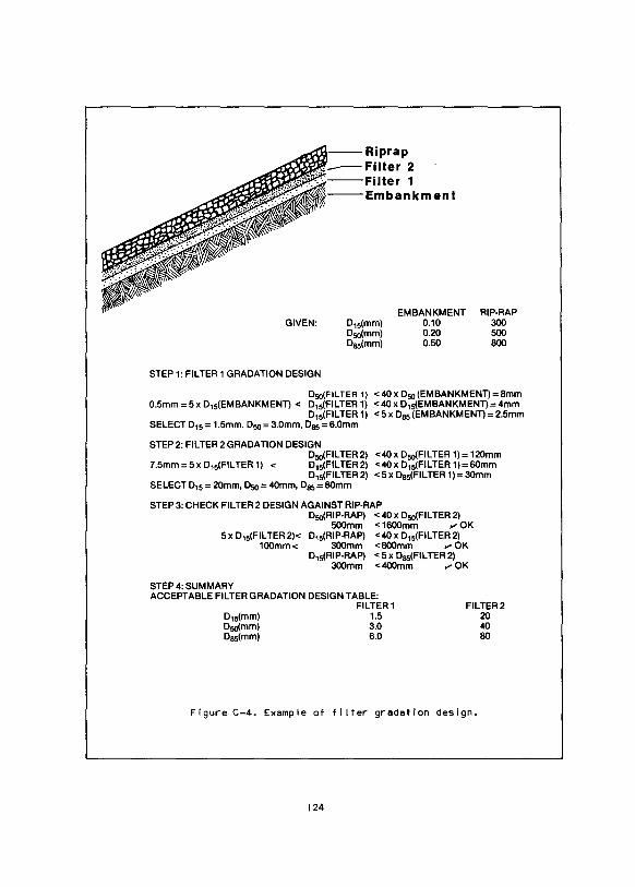
.-.• ..,--- Riprap Filter 2 Filter 1
~'0~"'---Emba n km en I
GIVEN:
STEP 1: FILTER 1 GRADATION DESIGN
D15(mm) Dso(mm) D85(mm)
EMBANKMENT 0.10 0.20 0.50
RIP-RAP 300 500 800
D50(FILTER 1) <40x D50 (EMBANKMENT)=8mm 0.5mm = 5 x D15(EMBANKMENT) < D15(FILTER 1) < 40 x D15(EMBANKMENT) = 4mm
D15(FILTER 1) <5x D85 (EMBANKMENT)=2.5mm SELECT D15 = 1.5mm, D50 = 3.0mm, D85 = 6.0mm
STEP 2: FILTER 2 GRADATION DESIGN D50(FILTER 2) <40 x Dso(FILTER 1) = 120mm
7.5mm =5x D15(FILTER 1) < D15(FILTER2) <40x D15(FILTER 1)=60mm D15(FILTER2) <5x D85(FILTER 1)=30mm
SELECT D15 = 20mm, D50 = 40mm, D85 = 80mm
STEP 3: CHECK FILTER 2 DESIGN AGAINST RIP-RAP Dso(RIP-RAP) < 40 x Dso(FILTER 2)
500mm < 1600mm "'OK 5 x D15(FIL TEA 2)< D15(RIP-RAP) <40 x D15(FILTER 2)
1 OOmm < 300mm < 800mm ., OK D15(RIP-RAP) < 5 x D85(FILTER 2)
300mm <400mm "'OK
STEP 4: SUMMARY ACCEPTABLE FILTER GRADATION DESIGN TABLE:
D15(mm) Dso(mm) Das(mm)
FILTER 1 1.5 3.0 6.0
FILTER2 20 40 80
Figure C-4. Example of fi Iter gradation design.
124

a b
Figure C-5. Schematic showing plan view of end protection configurations: el extension out of the zone of erosion with a potential reduction In thickness, and bl increasing the thickness at the ends of the revetment.
The base of the riprap revetment can be undercut by scour of the bed
if the toe is not protected. Extending the riprap layer below the level
of the bed and backfi I ling is recommended !Figure C-6al. If this cannot
be done, the riprap layer should be continued on the channel bed with an
Increased thickness to provide material to fi I I any scour holes that de
velop, thus preventing the scour from undercutting the riprap !Figure C-6bl.
125

Water Leve7
'------:fhickness Depends on Potential for Scour
a b
Figure C-6. Schematic showing cross section of toe protection configurations: al extension of the riprap below the dry bed and backfi I I ing, and bl placement of extra material along the bed to launch itself into developing scour holes.
REFERENCES
California Division of Highways. 1960. Bank and Shore Protection in
California Highway Practice. Sacramento: Documents Section, State of
California.
Karaki, S., K. Mahmood, E. V. Richardson, D. B. Simons, and M. A. Stevens.
1974. Highways in the River Environment, Hydraulic and Environmental
Design Considerations, Prepared for the U. S. Federal Highway Adminis
tration.
Neill, c. R., ed. 1973. Guide to Bridge Hydraulics. Published for Roads and
Transportation Association of Canada, by Univ. of Toronto Press. 191 pp.
U. S. Corps of Engineers. 1970. Hydraulic Design of Flood Control Channels,
Engineering and Design. Manual No. EM-I I 10-2-1601.
Winkley, B. R. 1971. Practical Aspects of River Regulation and Control,
In: River Mechanics, Vol. I. Hsien Wen Shen, ed., Prof. of Civi I Eng.,
Colorado State University.
126
APPENDIX D
DESIGN OF PITS
There are two basic designs to consider when mining floodplain gravel by
pit excavation: pit not connected, or pit connected to an active channel. A
properly designed unconnected pit can provide waterfowl, shorebird, and amphib
ious mammal habitat. If the pit is connected to the active channel, the pit
can also provide fish habitat. The outlet channel of the connected pit allows
fish that become trapped in the pit during high water to emigrate from the pit
at any time. If the pit is unconnected, it should be protected from the 20-
year flood. Fish trapped during these floods are considered lost from the
river population.
SHAPE AND DEPTH
The desired configuration for a gravel pit excavated in an inactive
floodplain or terrace is long and narrow, in the shape of a channel, with a
variety of depths !Figure D-1 l. If the pit is connected to the river or fish
are to be stocked in the pit, the mean depth should be greater than 2.5 m to
allow fish survival during winter. For a pit with a configuration as shown in
Figure D-1, the following are two examples of depth regimes that wi I 1 result
in a mean depth of 2.5 m:
A. For a minimum mean depth with a minimum of littoral area
Mean of depth
i nterva I lml
0.5
1.5
2.5
3.5
4.5
Maximum depth: 5 m
Mean depth: 2.5 m
127
Percent of
pit area
25
10
10
50
5

~
Figure D-1. Desired general configuration of a gravel pit connected to the active channel.

B. For 8 minimum me8n depth with 8 m8ximum littor81 8re8
Mean of depth
interval lml
0.5
1.5
2.5
3.5
4.5
5.5
Maximum depth: 6.0 m
Me8n depth: 2.5 m
Percent of
pit 8re8
35
10
10
15
25
5
A pit with greater I ittoral area generally allows greater productivity
and is preferred for waterfowl, shorebirds, 8nd fish. In both of the 11bove
examples an increased me11n depth wi I I decre11se the probabi I ity of fish winter
noortal ity. If more gravel is required, increasing depth is preferred over
increasing the surf11ce area of disturbance.
METHOD FOR CALCULATING MEAN DEPTH OF PIT
To obtain 11n estimate of the me11n depth of 11 designed pit, the following
procedures can be used.
A. Determine the 1-m lor other unit of me11surel contour intervals for the
pit.
B. Determine the percent of surface arealsl consisting of a particular
1-m depth interval [i.e., 0-1 = 0.35; 1-2 = O.IO; ••• ;In-1 l-n = sn,
where n =number of depth intervals].
129

C. Multiply the midpoint of eech 1-m depth intervel ldl by the percentege
of aree composed of thet interval [!i.e., d x s = 10.51 10.351; 11.51
(O.IOI, ••• ,Idnl(snl).
D. Meen depth= sum of elI products in c. [i.e., meen depth t ds
(0.5110.351 + 11.5110.101 + ••• + ldni(Sn).
The Teble below conteins exemple celculetions of meen depth of the pit
shown in Figure D-1. The letters refer to the four steps listed ebove.
c A B Midpoint Product of
Contour Surfece eree of contour midpoint end
i ntervel (he or interval percentage area
lml other unit I ($) (ml lml
0-1 1.28 33 0.5 0.17
1-2 0.64 17 1.5 0.26
2-3 0.52 14 2.5 0.35
3-4 1.08 28 3.5 0.98
4-5 0.30 8 4.5 0.36
Tote I 3.82 100 D 2.12 = meen depth
130
APPENDIX E
FISH PASSAGE STRUCTURES
PROVIDING FOR FISH PASSAGE OR CULVERT GUIDELINES
Fish passage structures should be provided when it is necessary to cross
drainages. Bridges are preferable for fish passage; however, they are often
economically unfeasible because of the short project life and remoteness of
most floodplain gravel removal operations. If mature timber is avai leble,
it may be used for effective and economical log culverts. Metal culverts,
although generally undesireable in temporary roads, are usually utilized, but
must be instal led properly to provide adequate fish passage. The following
guidelines on fish passage structures ere a synopsis of those developed by
Dryden and Stein I 1975) and U. S. Department of Agriculture I 1979l for the
protection of fish resources. The former document presents guide I ines to be
considered in Northwest Territories road design while the latter deals specif
ically with how to properly design fish passage structures in Alaska roadway
drainages. Refer to these documents for more detai I and specifics.
Hydrological Design
Structure Velocities.
A. In general, the average velocity should not exceed 0.9 m/s during fish
migration periods. Many species require velocities considerably less
than this during migration periods and fish passage can be impeded at
velocities of 0.3 m/s !Figure E-1 l.
B. A 3-day delay period 13 days of velocities in excess of those required
for passage! should not be exceeded during the mean annual flood
12.33-year recurrence interval flood). A 7-day delay period should not
be exceeded in the design flood.
131

5
40
-30 E u -
10
10 20 30 40 50 60 70 80 WATER VELOCITY (em/sec)
Figure E-1. The relationship between fish fork length and ability to move 100m against water velocities of 0-80 em/sec in 10 min. The same curves may elso be used to indicate the ebi lity to make progress against these currents over shorter distances. For instance, to cross e 50-m barrier in 10 min the curves should be shifted 8 em/sec to the right; to cross e 25-m barrier in 10 min the curves should be shifted 12 em/sec to the right. The line for char is derived from the hypothetical equation V = 17 L'·" end represents the measured value In these experiments (from Jones 19731.
132
Minimum Weter Level. The weter level in the culvert should not be less
then 20 em during the open-weter seeson unless fish pessege is not required.
Structure Design
Shepe.
A. If suiteble timber is avei leble, netive log stringer or rough-sewed
timber bridges end log culverts ere the most desireble temporery
structures for the passege of fish. They meintain the neturel streem
bed end gradient end ere easy to remove.
B. Arch culverts with en open bottom are preferred culverts for permenent
roads. These culverts retein neturel bed material. Closed erch cul
verts ere second in preference.
C. Horizontel elI ipse culverts cen meintein streem flow width end neturel
bed meteriel if the culvert invert is placed below the stream bed
elevation.
D. Circular culverts ere impractical for fish pessege unless instal led
as described by U. S. Department of Agriculture ( 19791, summarized in
the following section.
Instal let ion end Design.
A. Culvert inverts should be laid a minimum of 15 em below normal stream
bed elevation. The Alaska State Pipeline Coordinator's Office often
recommends a burial depth of 201 of culvert diameter.
B. Inverts should be designed to prevent hydrostatic up I ift at the down
stream or upstream end.
C. The culvert gradient should be kept as close to 01 gradient as pos
sible so that upstreem or downstream velocity barriers ere not
created.
133
Capacity. Culverts should have sufficient capacity to pass the design
flood with no backwatering or pending at the upstream end.
Location.
A. Culverts should not be placed where a channel cutoff or diversion
wi I I result.
B. The culvert should be placed so that its discharge is not directed
at an unstable bank.
Multiple Culverts. A 1.8 m spacing should be present between adjacent
culvert wal Is. This wi I I provide a downstream backwater area for fish to rest
in before attempting passage.
REFERENCES
Dryden, R. L., and J. N. Stein. 1975. Guidelines for the Protection of the
Fish Resources of the Northwest Territories During Highway Construction
and Operation: Environment Canada. Fisheries and Marine Service Tech.
Rept. Series·No. CEN/T-75-1. 32 pp.
Jones, D. R. 1973. An Evaluation of the Swimming Performance of Several Fish
Species from the MacKenzie River. Dept. Environment, Fisheries
and Marine Service, Winnipeg, Man. 53 pp.
U. S. Dept. of Agriculture. 1979. Roadway Drainage Guide for Instal I ing
Culverts to Accommodate Fish. Engineering and Aviation Management Div
ision, Forest Service. Alaska Region Report No. 42. 121 pp.
134

APPENDIX F
SETTLING PONDS AND WASTEWATER TREATMENT
WASTEWATER TREATMENT
The Federal-State effluent guidelines indicate that total suspended
sol ids ITSSI is the main effluent parameter that must be monitored during
mining and processing of construction sand and gravel I Hal I and Kosakowski
19761. The present EPA requirement is that the TSS of a gravel mining effluent
should not exceed 30 mg/t at any time. In order to accomplish this final
concentration, a series of settling ponds and often a coagulant are normally
required. Specific needs wi I I vary according to the amount of washing neces
sary and the sci I characteristics of the material. In a washing operation,
wash water can usually be recycled without need for discharge. In this case
the amount of settling required wi I I depend on the need of the operator for
clean water. Generally, recycled water with a TSS of less than 200 mglt is
suitable for reuse.
Specific detai Is on how to design and operate settling ponds are dis
cussed in Monroe I 19731 and this document should be referenced if additional
information is needed. Following is a brief synopsis of his major recommenda
tions.
Settling Ponds- pond with an outlet
A. Used to clarify water for reuse or effluent discharge.
B. Cross-sectional area of the pond must be large so horizontal velocity
is very slow.
C. Water must enter pond over most of the width to make the entire pond
effective le.g., to avoid short circuiting, channel formation).
135

D. The outlet must be wide to skim off the top clear water and maintain a
low horizontal velocity.
Fi Iter Ponds- pond without an outlet
A. Used where there is no discharge or recirculation.
B. Water table must be low enough that water wil I fi Iter out, not into
the pond. Pond berms must be high enough to guard against floods.
C. Wal Is and bottom of the pond must be porous to allow outflow. Ponds
seal more slowly if they are kept ful I so alI the area of wal Is and
bottom are working.
D. Pond must be large enough so ii wi I I not seal.
E. Coagulants should not be used in fi Iter ponds because they shorten the
I ife of these ponds.
F. It is best to precede the fi Iter pond with a settling pond for heavy
particle settlement.
Coagulation
A. Used when there is a high concentration of solids that wi I I not settle
or there is I imited area for settling ponds, or both.
B. Must be thoroughly mixed to be efficient.
C. Works better in warm water; settlement rate is doubled for every
35°C increase in temperature.
D. Commonly used coagulants are: aluminum sulphate laluml, ferrous sul
phate lcopperasl, calcium hydroxide (hydrated limel, calcium oxide
I quick I imel, sodium aluminate, sodium carbonate lsoda ashl, ferric
chloride lferrisull, sodium silicate.
136

E. Multipond arrangement may be most suitable.
F. Coagulant should be added to the water at inlet to each pond.
REFERENCES
Hall, E. P., and M. W. Kosakowski. 1976. Mineral Mining and Processing
Industry. Development Document for Interim Final Effluent Limitations
Guide I ines and Standards of Performance. Environmental Protection Agency,
Effluent Guide I ines Division, Office of Water and Hazardous Materials.
Wash., D. C. 432 pp.
Monroe, R. G. 1973. Wastewater Treatment Studies in Aggregate and Concrete
Production. Environmental Protection Technology Series EPA-R2-73-003.
Environmental Protection Agency, Office of Research and Monitoring,
Washington, D. C. 108 pp.
137

APPENDIX G
EFFECTS OF BLASTING ON AQUATIC ORGANISMS
Although infrequently required on floodplain sites, blasting may be
uti I ized during certain phases of gravel removal. Teleki end Chamberlain
( 197Bl developed a series ~f curves and equations to estimate the fatality
radius of a particular charge (based on en explosive with a detonation veloc
ity of 4940-5490 m/s) in relation to certain types of fish !Figure G-11.
A number of studies have evaluated the effects of blasting on a particu
lar organism or groups of organisms. Table G-1 summarizes the results of some
of these studies end indicates the range of sensitivities shown by aquatic
organisms to pressure changes.
The force generated by a particular charge can be determined at various
distances by referring to Table G-2.
REFERENCES
Alpin, J. A. 1947. The effect of explosives on marine life. Cal if. Fish and
Game 33111:23-27.
Baxter, R. E. 1971. Effects of Explosives Detonated in Ice on Northern Pike,
Kuskokwim River, 1970. Alaska Dept. Fish and Game Info. Leaflet 154.
IB pp.
Falk, M. R., and M. J. Lawrence. 1973. Seismic Exploration: It's Nature end
Effect on Fish. Fish end Meine Service Central Region. Tech. Rept. Series
No. CEN/T 73-9.
Henson, H. 1954. Fur seal control program, Copper River end Bering River
area. Alaska Dept. of Fisheries.
139

Hubbs, C. L., and A. B. Rechnitzer. 1952. Report on experiment designed to
determine effects of underwater explosioQs on fish I ife. Cal if. Fish and
Game 38131:333-366.
Rasmussen, B. 1967. The Effect of Underwater Explosions on Marine Life.
Bergen, Norway. 17 pp.
Teleki, G. c., and A. J. Chamberlain. 1978. Acute effects of underwater con
struction blasting on fishes in Long Point Bay, Lake Erie. J. Fish Res.
Bd. Canada 35: I 191-1 198.
U. S. Navy. 1970. U. S. Navy Diving Manual. NAVSHIPS 0994-001-9010.
140
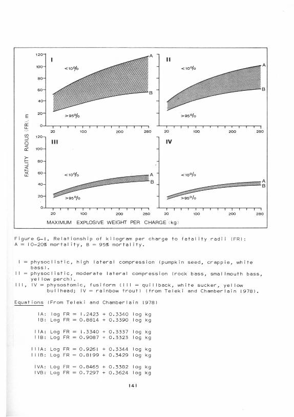
120
II 100
80
60
40
E 20l >95°/o >95°/o
a: 0 LJ._ - 20 100 200 280 20 100 200 280 C/)
120l ::::l Ill 0 IV
<( 100 a:
>-I- 80 ::::; <(
~ LJ._ < 10u/o <10°/o 601
40 ,,-;:s£;.?.:" ,.-'-~:-k· _:.;- '.·· ... ~p)¥4%}"'''*'~'"'* A 8
20
0
20 100 200 280 20 100 200
MAXIMUM EXPLOSIVE WEIGHT PER CHARGE <kg l
Figure G-1. Relationship of kilogram per charge to fatality radii <FRI: A= 10 -20% mortality, B = 95% mortality .
physocl istic, high lateral compression (pumpkin seed, crappie, wh i te bass I.
280
II = physocl istic, moderate lateral compression (rock bass, smallmouth bass, ye I I ow perch I •
Ill, IV= physostom ic, fusiform (Ill= quillback, white sucker, yellow bullhead; IV = rainbow troutl (from Telek i and Chamberla i n 19781 .
Equations (From Teleki and Chamberlain 1978 1
lA: log FR = I. 2423 + 0 . 3340 log kg 18 : Log FR = 0 . 8814 + 0.3390 log kg
II A: Log FR = 1. 3340 + 0 . 3337 log kg I IB: Log FR = 0 . 9087 + 0 . 3323 log kg
I I lA: Log FR = 0.926 1 + 0 . 3344 log kg II I B: Log FR = 0.8 199 + 0 . 3429 log kg
IVA: L og FR = 0 . 8465 + 0 . 3382 log kg I VB: Log FR = 0 .7297 + 0.3624 log kg
141

~
"'
Teble G-1. Lethal end Sublethal Blesting Pressures of Selected Aquetic Organisms
A. Blasting with verious "high explosives".
Force Organism lki lopascalsl 8
Six month salmon & herring fry Fish with air bladder Northern pike Arctic cisco and smal I Coregonidae Fur sea I Fish without eir bladder Oyster Blue crab Shrimp Salmon and herring fry w/o eir bladder
0.4 6-7 7
25 74 74 56-126
113-124 169
Effect
Lethal Lethal Lethal Lethal Letha I
Largely uninjured Low mort a I i ty
Lethal No effect
"Not greatly affected"
Reference
Rasmussen 1967 Hubbs & Rechnitzer 1952 Baxter 1971 Felk & Lawrence 1973 Hanson 1954 Alpin 1947 Rasmussen 1967 Rasmussen 1967
Rasmussen 1967
B. Blasting with "Hydromex" !Detonation velocity 4938-5486 m/secl.
Organism
Pumpkin seed Crappie White bess Gizzerd shed Ye I I ow perch Sma I I mouth bass Rock bess Freshwater drum Qui II back White sucker Yellow bullheed Reinbow trout Carp
80ne k i I op.,sc" I
Minimum lethal pressure
( k i I opesce Is l 8
30 30 30 39 40 65 65 73 76 73 73 85
7
6.896 pounds per squ8re inch.
Fatal pressure 195% mortal it~l (ki lopescalsl
69 73 88
73
76
100 150
Reference
Teleki & Chamberlain 197B (for alI organisms on I istl
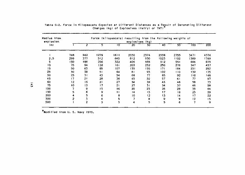
Table G-2. Force in Ki lopascals Expected at Different Distances as e Result of Detonating Different Charges lkgl of Explosives ltetryl or TNTia
Radius from Force lkilopascalsl resulting from the following weights of explosion ex~losives tksl
lml I 2 5 IO 20 30 40 50 100 200
I 748 942 1279 1611 2030 2324 2558 2755 3471 4374 2.5 299 377 512 645 812 930 1023 1102 1389 1749 5 150 188 256 322 406 465 512 551 694 875
10 75 94 128 161 203 232 256 276 347 437 15 50 63 85 107 135 155 171 184 231 292 25 30 38 51 64 81 93 102 110 139 175 30 25 31 43 54 68 77 85 92 116 146 45 17 21 28 36 45 52 57 61 77 97 60 12 16 21 27 34 39 43 46 58 73
"'" 75 10 13 17 21 27 31 34 37 46 58 "' 100 7 9 13 16 20 23 26 28 35 44 150 5 6 9 II 14 15 17 18 23 29 200 4 5 6 8 10 12 13 14 17 22 300 2 3 4 5 7 8 9 9 12 15 500 I 2 3 3 4 5 5 6 7 9
8 Modified from U. S. Navy 1970.

APPENDIX H
STANDARD FORMULA AND CONVERSION FACTORS
CONTINUITY OF FLOW
Q = A1V1 = A2V2
where Q = discharge
A1 =cross sectional area of the flow at I
v1 =mean flow velocity at I
A2
=cross sectional area of the flow at 2
v2
=mean flow velocity at 2
VELOCITY OF CULVERT FLOW
Culvert Flowing Full !Outlet Control!
where
v = Q T
v mean flow velocity in culvert
Q = discharge through culvert
A= cross sectional area of culvert
Cross sectional areas of plate steel arch, pipe-arch, and circular culverts
of various sizes are I isted in Tables H-1, H-2, and H-3. Estimates of cross
sectional areas of circular culverts whose inverts ere buried below the stream
bed can be obtained from Tables H-1 or H-2, using measured or estimated span
and rise values.
Culvert Flowing Partially Full I inlet Control I
Outlet velocity may be approximated by computing the mean velocity for the
culvert cross section using Manning's equation. Manning's equation can be
written:
145

Table H-1. Cross-Sectional Area of Plate Stee) Arch Culverts
Span Rise Cross-Sectional Area
m ft-in m ft-in m2· ft 2
1.83 6-0 0.70 2-31;, 0.93 10 2.13 7-0 0.86 2-10 1. 39 15 2.44 8-0 1.02 3-4 1.86 20 2.74 9-0 1.18 3-101;, 2.46 261;, 3.05 10-0 1. 35 4-5 3.16 34 3.35 11-0 1. 36 4-51;, 3.44 37 3.66 12-0 1. 52 5-0 4.18 45 3.96 13-0 1. 55 5-1 4.55 49 4.27 14-0 1. 70 5-7 5.39 58 4.57 15-0 2.01 6-7 6.97 75 4.88 16-0 2.16 7-1 7.99 86 5.18 17-0 2.18 7-2 8.55 92 5.49 18-0 2.34 7-8 9.66 104 5.79 19-0 2.49 8-2 10.96 118 6.10 20-0 2.53 8-31;, 11.52 124 6.40 21-0 2.69 8-10 13.01 140 6.71 22-0 2.72 8-11 13.56 146 7.01 23-0 3.00 9-10 15.89 171 7.32 24-0 3.15 10-4 17.47 188 7.62 25-0 3.31 10-101;, 19.23 207 7.62 25-0 3.81 12-6 22.95 247
146

Table H-2. Cross-Sectional Area of Pipe-Arch Culverts
SPAN
Span Rise Cross-Sectional Area m ft-in m ft-in m2 te
0.46 1-6 0.28 0-11 0.10 1.1 0.63 2-1 0.41 1-4 0.20 2.2 0.91 3-0 0.56 1-10 0.41 4.4 1.27 4-2 0. 79 2-7 0.81 8.7 1.47 4-10 0.91 3-0 1.06 11.4 1.65 5-5 1.02 3-4 1.33 14.3 1. 85 6-1 1. 40 4-7 2.04 22 2.13 7-0 1.55 5-1 2.60 28 2.41 7-11 1. 70 5-7 3.25 35 2.69 8-10 1.85 6-1 3.99 43 2.97 9-9 2.01 6-7 4.83 52 3.25 10-8 2.11 6-11 5.39 58 3.53 11-7 2.26 7-5 6.22 67 3.81 12-6 2.41 7-11 7.25 78 4.09 13-5 2.57 8-5 8.27 89 4.34 14-3 2.72 8-11 9.38 101 4.67 15-4 2.82 9-3 10.13 109 5.00 16-5 3.02 9-11 11.71 126 5.03 16-6 3.35 11-0 13.29 143 5.31 17-5 3.51 11-6 14.68 158 5.66 18-7 3.66 12-0 16.17 174 5.94 19-6 3.81 12-7 17.65 190 6.27 20-7 4.01 13-2 19.88 214
147

Teble H-3. Cross-Sect ionel Area 'of Circule.r Culverts
Inside Diameter Cross-sectional area
m ft-in m2 ft 2
0.30 1-0 0.074 0.8 0.46 1-6 0.17 1.8 0.61 2-0 0.29 3.1 0.76 2-6 0.49 5.3 0.91 3-0 0.66 7.1 1.07 3-6 0.89 9.6 1.22 4-0 1.17 12.6 1.37 4-6 1.48 15.9 1. 52 5-0 1.82 19.6 1.83 6-0 2.63 28.3 2.13 7-0 3.58 38.5 2.44 8-0 4.67 50.3 2.74 9-0 5.91 63.6 3.05 10-0 7.29 78.5 3.35 11-0 8.83 95.0 3.66 12-0 10.51 113.1 3.96 13-0 12.33 132.7 4.27 14-0 14.30 153.9 4.57 15-D 16.42 176.7 4.88 16-0 18.68 201.1 5.18 17-0 21.09 227.0 5.49 18-0 23.64 254.5 5.79 19-0 26.34 283.5 6.10 20-0 29.19 314.2
148
where
v =.!. R2/3 s112 n
V =mean flow velocity in culvert lm/sl
n =Menning roughness coefficient
R =hydraulic radius lml
S = slope of culvert invert lm/ml
Approximate values of roughness coefficient are I isted below:
smooth I ined culverts
corregated metal culverts
culverts partially fi I led with gravels and cobbles
n = 0.012
n = 0.024
n = 0.036
Estimates of the hydraulic radius of culverts can be obtained from Figure
H-1. A nomograph for solving Menning's equation and an example problem ere
given in Figure H-2.
DISCHARGE MEASUREMENTS
Standard Measurement Technique
The U. S. Geological Survey has developed a technique for measuring
the discharge in a river !Buchanan end Somers, 1969!. A relatively straight
and uniform reach of river should be selected for taking discharge measure
ments. The width of the channel Is! should be divided into a number of sub
sections 125 or more ere recommended) that ere often, but do not have to
be, the same width !Figure H-3). Velocities are measured at each of the ob
servation points at one or more depths depending on the flow depth, desired
accuracy, end rete of change of the flow. Generally speaking, the accuracy
of the mean velocity increases with increasing number of current measurements
at one observation point. An exception to this is when the flow is changing
rapidly, thus requiring that the discharge measurements be completed in a
short time span. Equations for calculating mean velocity ere given in Figure
H-3 for three common measurement techniques. Discharge in each subsection
is the product of the mean velocity in the subsection and the cross-sectional
149
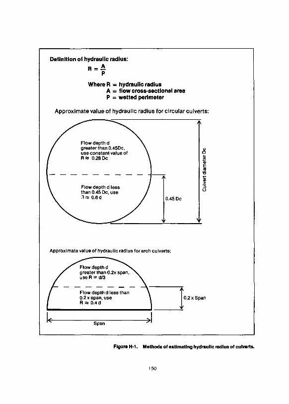
Definition of hydraulic radius:
R=~ p
Where R = hydraulic radius A = flow cross-sectional area P = wetted perimeter
Approximate value of hydraulic radius for circular culverts:
Flowdepthd greater than 0.45Dc, use constant value of R.::: 0.28 De
Flow depth d less than 0.45 De, use ."!.::: 0.6d 0.45 De
Approximate value of hydraulic radius for arch culverts:
Flow depth d less than 0.2 x span, use R ~ 0.4d
Span
r0.2>Spao ----=-
Figure H·1. Methods of estimating hydraulic radius of culverts.
150
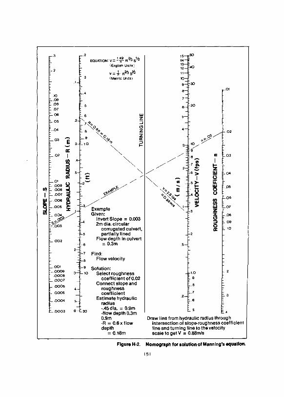
.3 EQUATION: V= 1 ·~9 R% slf2
I English Units) I ~;;_F40 .2 1-
v=ir R%sl2 (Metric Units)
~
30
~ A I Q r r-.01
.tO
.09
.08 r I - l-20 .07
.06 .6 w
.2 " z
.05 .7~q ::J
.04 C)
8~ z ~-02
r·9 ~6>.., z o'~-
.03 -;; a: ~ :::l
~ ~ f- 3
a:: .02 I
~ / 8 c L03
0 / ..... I Ill ::) / 7.2- ... ~ 5 ""- /
2 s> z ..... w 1:-.04 a:: - /
~ '! I 0
0~~~ ,::o ~/ 5)- u:: ... 8 ~.05 "' \, E 0 1. .oo1 ~ ~ ·9 ._. 40
Qli ~6 ...1 ~
l" ~ 006 Q / 6>.., w
.005 ~ "~ 1 > w .07
ul ~~- / Example 3 z Given: ::1: .06
Invert Slope = 0.003 CJ 2m dia. circular ::) .09
0 corrugated culvert, a:: .10
partially lined .002 + Flow depth in culvert
= 0.3m I .5
Find: Flow velocity
.001 9 Solution:
.0009 10 Select roughness r L2
.0008 .0007 coefficient of 0.02 .9
.0006 Connect slope and .8
roughness .ooos coefficient .7
Estimate hydraulic .2 ~3
.0004 .6 radius
.0003 6--L20 -.45 dia. = 0.9m I t...5 ·flow depth 0.3m E..4
0.9m Draw line from hydraulic radius through -R = 0.6 x flow intersection of slope-roughness coefficient depth line and turning line to the velocity
= 0.18m scale to get V = 0.88m/s
FlgureH-2. Nomograph for solution of Manning's equation.
151
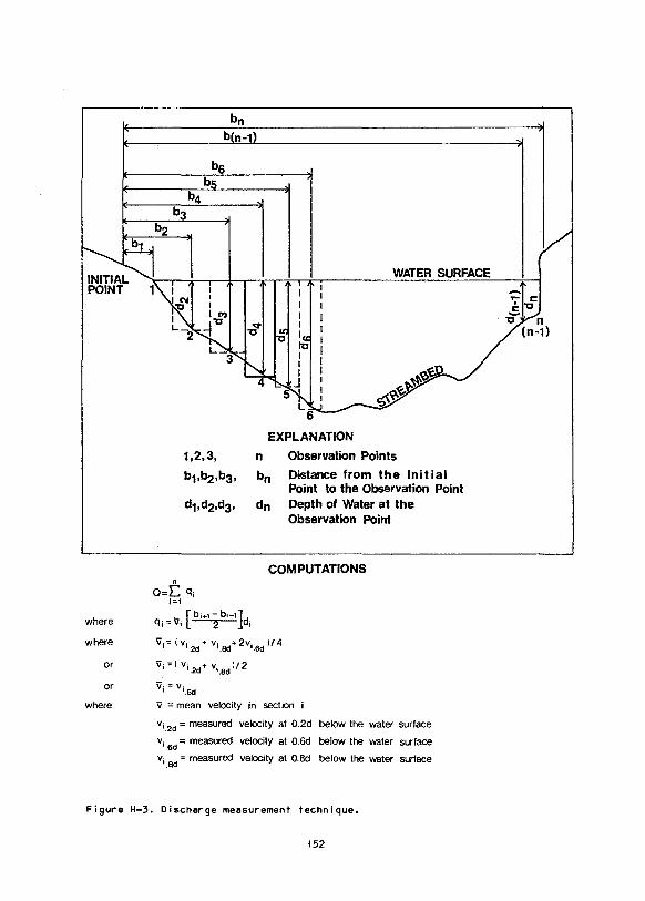
where
where
or
or
where.
bs
O=f:. q; i=1
b(n-1)
EXPLANATION
n Observation Points
bn Distance from the Initial Point to the Observation Point
dn Depth of Water at the Observation Point
COMPUTATIONS
q; = V; ( b;+12 b;-1 ]d;
V;= ( V;.2d + V;.8d+2v;.6d )/4
'ii; =( V;.2d,. V;.Bd)/ 2
vi= vi.6d
'ii = mean velocity in section i
v;.2d =measured velocity at 0.2d below the water surface
v;_6
d = measured velocity at 0.6d below the water surface
v; = measured velocity at O.Bd below the water surface .Sd
Figure H-3. Discharge meesurement technique.
152
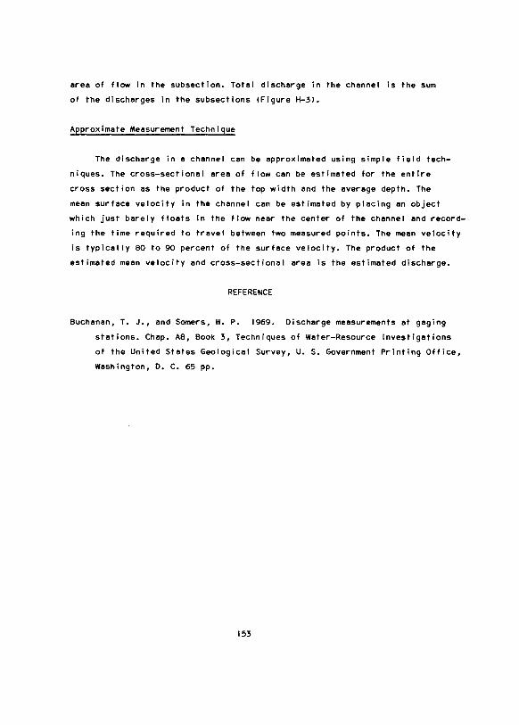
erea of flow in the subsection. Total discharge in the channel is the sum
of the discharges in the subsections (Figure H-31.
Approximate Measurement Technique
The discharge in a channel cen be approximated using simple field tech
niques. The cross-sectional area of flow can be estimated for the entire
cross section as the product of the top width and the average depth. The
mean surface velocity in the channel can be estimated by placing an object
which just barely floats in the flow near the center of the channel and record
ing the time required to travel between two measured points. The mean velocity
is typically 80 to 90 percent of the surface velocity. The product of the
estimated mean velocity and cross-sectional area Is the estimated discharge.
REFERENCE
Buchanan, T. J., and Somers, w. P. 1969. Discharge measurements at gaging
stations. Chap. AS, Book 3, Techniques of Water-Resource Investigations
of the United States Geological Survey, U. S. Government Printing Office,
Washington, D. C. 65 pp.
153
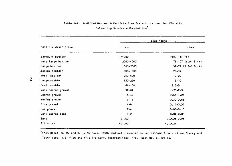
-IJ1
""
Teble H-4. Modified Wentworth Perticle Size Scele to be used for Visuel ly
Estimeting Substrete Composition8
Size renge
Perticle description mm inches
Memmouth boulder >4000 >157 I 13 ft)
Very lerge boulder 2000-4000 78-157 16.5-13 ftl
Lerge bou I der 1000-2000 39-79 13.3-6.5 ftl
Medium boulder 500-1000 20-39
Sme I I bou I der 250-500 10-20
Lerge cobble 130-250 5-10
Sme I I cobb I e 64-130 2.5-5
Very coerse grevel 32-64 1.25-2.5
Coerse grevel 16-32 0.63-1 .25
Medium grevel 8-16 0.32-0.63
Fine grevel 4-8 0.16-0.32
Pee grevel 2-4 O.OB-0. 16
Very coerse send 1-2 0.04-0.08
Send 0.062-1 0.0024-0.04
Si I t-cley <0.062 <0.0024
8From Bovee, K. D. end R. T. Mi lhous. 1978. Hydreul ic simuletion in instreem flow studies: Theory end
Techniques. U.S. Fish end Wildlife Serv. lnstreem Flow Info. Peper No. 5. 125 pp.

Table H-5. Conversion Factors
To convert into Multiply by
Length mm inches 0.03937
mm feet 3.281 X 10⁻³
em inches 0.3937
feet -2 em 3.281 X 10
m feet 3.281
m yards 1.094
km miles 0.6214
Aree 2 square feet 10.76 m 2 square yards 1.196 m
ha acres 2.471
km2 square mile 0.3861
Volume 3 cubic yards 1.308 m
Speed m/s feet per second 3.281
Volume flow rete m3ts cubic feet per
second 35.31
Mass kg pound-mass 2.205
Force N pound-force 0.2248
N Ki logrem-force 0.1020
Pressure kPe pound-force per
square inch 0.1450
Temperature oc OF 9/5
!then add 321
Concentration mg/1. parts per mi II ion -I .0
155


APPENDIX I
GLOSSARY
abandoned channel --A channel that was once an active or high-water chan
nel, but currently flows only during infrequent floods.
active channel --A channel that contains flowing water during the ice-free
season.
active floodplain-- The portion of a floodplain that is flooded frequently;
it contains flowing channels, high-water channels, and adjacent bars,
usually containing I ittle or no vegetation.
aesthetics --An enjoyable sensation or a pleasurable state of mind, which
has been instigated by the stimulus of an outside object, or it may
be viewed as including action which wil I achieve the state of mind de
sired. This concept has a basic psychological element of individual
learned response and a basic social element of conditioned social atti
tudes. Also, there can be ecological conditioning experience because
the physical environment also affects the learning process of attitudes.
algae -- Primitive plants, one or many-eel led, usually aquatic and capable
of elaborating the foodstuffs by photosynthesis.
aliquot-- A portion of a gravel removal area that is worked independently,
often sequentially, from the other portions of the area.
a I I uv i a I r i ver A river which has formed its channel by the process of
aggradation, and the sediment by which it carries !except for the wash
load) is similar to that in the bed.
arctic-- The north polar region bounded on the south by the boreal forest.
157

armor layer --A layer of sediment that is coarse relative to the material
underlying it and is erosion resistant to frequently occurring floods;
it may form naturally by the erosion of finer sediment, leaving coarser
sediment in place or it may be placed by man to prevent erosion.
aufeis --A~ !ce feature that is formed by water overflowing onto a surface,
such as river ice or gravel deposits, and freezing, with subsequent
layers formed by water overflowing onto the ice surface itself and
freezing.
backwater analysis --A hydraulic analysis, the purpose of which is to
compute the water surface profile in a reach of channel with varying
bed slope or cross-sectional shape, or both.
bank-- A comparatively steep side of a channel or floodplain formed by an
erosional process; its top is often vegetated.
bank-ful I discharge-- Discharge corresponding to the stage at which the
overflow plain begins to be flooded.
bar--Anal luvial deposit or bank of sand, gravel, or other material, at
the mouth of a stream or at any point in the stream flow.
beaded stream-- A smal I stream containing a series of deep pools intercon
nected by very smal I channels, located in areas underlain by permafrost.
bed -- The bottom of a watercourse.
bed load Sand, si It, gravel or soi I and rock detritus carried· by a stream
on, or immediately above its bed.
bed load material -- That part of the sediment load of a stream which is
composed of particle sizes found in appreciable quantities in the shift
ing portions of the stream bed.
158
bed, moveble- A streem bed mede up of meteriels reedily trensporteble by
the streem f I ow.
bed, streem --The bottom of 11 streem below the low summer flow.
breided river-- A river conteining two or more interconnecting chennels
seperated by unvegetated gravel bers, spersely vegeteted islends, end,
occesionel ly, heevily vegeteted islends. Its floodplein is typicel ly
wide end spersely vegeteted, end conteins numerous high-weter chennels.
The laterel stebi I ity of these systems is quite low within the boun
deries of the ective floodplein.
cerrying cepeclty, biological -- The meximum everege number of e given orgen
ism thet cen be meinteined indefinitely, by the habitat, under a given
regime !in this cese, f I owl •
cerrying cepacity, discherge --The meximum rete of flow thet e chennel is
capeble of pessing.
chennel --A nature! or ertificiel weterwey of perceptible extent which
periodically or continuously conteins moving weter. It has a definite
bed end benks which serve to confine the weter.
configuretion --The pettern of e river chennellsl es it would eppeer by
looking verticel ly down et the weter.
contour-- A line of equel elevetion ebove e specified detum.
cover, benk -- Arees essocieted with or edjacent toe streem or river thet
provide resting shelter end protection from predetors- e.g., undercut
banks, overhenging vegetetion, accumuleted debris, and others.
cover, fish-- A more specific type of instreem cover, e.g., pools,
boulders, weter depths, surfece turbulence, end others.
159
cover, instreem -- Arees of shelter in e streem chennel thet provide equetic
orgenisms protection from predetors ore piece in which to rest, or
both, end conserve energy due to a reduction in the force of the cur
rent.
cross section eree-- The eree of e stream, chennel, or waterway opening,
usually teken perpendicular to the streem centerline.
current --The flowing of weter, or other fluid. Thet portion of e stream
of weter which is moving with e velocity much greeter than the everege
or in which the progress of the water is principally concentrated !not
to be confused withe unit of measure, see velocity!.
detum --Any numericel or geometrical quantity or set of such quantities
which mey serve as a reference or base for other quentities. An egreed
standard point or plene of stated elevation, noted by permanent bench
merks on some solid immovable structure, from which elevetions are meas
ured, or to which they are referred.
dewater --The dreining or removal of weter from an enclosure or channel.
discherge --The rate of flow, or volume of water flowing in e given streem
et e given piece and within a given period of time, expressed as cu
ft per sec.
dreinege area-- The entire erea drained by e river or system of connecting
streams such that alI streem flow originating in the area is discherged
through a single outlet.
dredge-- Any method of removing gravel from ective channels.
drift, invertebrete -- The equatic or terrestriel invertebrates which heve
been releesed from lbehevioral drift!, or heve been swept from (catas
trophic drift! the substrete, or have fa I len into the stream end move
or fleet with the current.
160

duration curve-- A curve which expresses the relation of alI the units of
some item such as head and flow, arranged in order of magnitude along
the ordinate, and time, frequently expressed in percentage, along the
abscissa; a graphical representation of the number of times given
quantities are equaled or exceeded during a certain period of record.
erosion, stream bed -- The scouring of material from the water channel and
the cutting of the banks by running water. The cutting of the banks
is also known as stream bank erosion.
fines-- The finer grained particles of a mass of soi I, sand, or gravel. The
material, in hydraulic sluicing, that settles last to the bottom of
a mass of water.
flood-- Any flow which exceeds the bank-ful I capacity of a stream or chan
nel and flows out on the floodplain; greater than bank-ful I discharge.
floodplain-- The relatively level land composed of primarily unconsolidated
river deposits that is located adjacent to a river and is subject to
flooding; it contains an active floodplain and sometimes contains an
inactive floodplain or terracelsl, or both.
flood probability-- The probabi I ity of a flood of a given size being
equaled or exceeded in a given period; a probabi I ity of I percent would
be a 100-year flood, a probability of 10 percent would be a 10-year
flood.
flow-- The movement of a stream of water or other mobile substances, or
both, from place to place; discharge; total quantity carried by a
stream.
flow, base-- That portion of the stream discharge which is derived from
natural storage- i.e., groundwater outflow and the draining of large
lakes and swamps or other sources outside the net rainfal I which
creates the surface runoff; discharge sustained in a stream channel,
161

not e result of direct runoff end without the effects of regulation,
diversion, or other works of man. Also cal led sustaining flow.
flow, leminer --That type of flow in e stream of weter in which eech par
ticle moves in a direction perel lei to every other particle.
flow, low-- The lowest discharge recorded over e specified period of time.
flow, low summer-- The lowest flow durin~ c typical open-water season.
flow, uniform-- A flow in which the velocities ere the same In both magni
tude end direction from point to point. Uniform flow is possible only
in e channel of constant cross section.
flow, varied-- Flow occurring in streams having e variable cross section
or slope. When the discharge is constant, the velocity changes with
each change of cross section end slope.
fork length-- The length of e (ish measured from the tip of the nose to the
fork in the tai 1.
freeze front --A surface thet may be stationery, which hes e temperature
of 0°C and is warmer on one side of the surface end colder on the
other.
frequency curve --A curve of the frequency of occurrence of specific
events. The event thet occurs most frequently is termed the mode.
gege --A device for indicating or registering magnitude or position in spe
cific units, e.g., the elevation of e water surface or the velocity
of flowing water. A steff graduated to indicate the elevation of a
water surface.
geomorphology -- The study of the form end •evelopment of lendscepe fea
tures.
162
habitat --The place where a population of animals I ives and its sur
roundings, both I iving and non I iving; includes the provision of life
requirements such as food and shelter.
high-water channel --A channel that is dry most of the ice-free season,
but contains flowing water during floods.
hydraulics-- The science dealing with the mechanical properties of fluids
and their application to engineering; river hydraulics deals with
mechanics of the conveyance of water in a natural watercourse.
hydraulic depth-- The average depth of water in a stream channel. It is
equal to the cross-sectional area divided by the surface width.
hydraulic geometry-- Those measures of channel configuration, including
depth, width, velocity, discharge, slope, and others.
hydraulic radius -- The cross-sectional area of a stream of water divided
by the length of that part of its periphery in contact with its contain
ing channel; the ratio of area to wetted perimeter.
hydrograph --A graph showing, for a given point on a stream, the discharge,
stage, velocity, or another property of water with respect to time.
hydrology-- The study of the origin, distribution, and properties of water
on or near the surface of the earth,
ice-rich material --Permafrost material with a high water content in the
form of ice, often taking the shape of a vertical wedge or a horizontal
lens.
impervious --A term applied to a material through which water cannot pass
or through which water passes with great difficulty.
163

inactive floodplain-- The portion of a floodplain that is flooded infre
quently; it may contain high-water and abandoned channels and is
usually lightly to heavily vegetated.
island-- A heavily vegetated sediment deposit located between two channels.
large river-- A river with a drainage area greater than 1,000 km2 and a
mean annual flow channel top width greater than 100m.
lateral bar-- An unvegetated or I ightly vegetated sediment deposit located
adjacent to a channel that is not associated with a meander.
Manning's equation -- In current usage, an empirical formula for the calcula
tion of discharge in a channel. The formula is usually written
Q = 1.49 R 2/3 5 112 A. n
mean flow-- The average discharge at a given stream location computed for
the period of record by dividing the total volume of flow by the number
of days, months, or years in the specified period.
mean water velocity The average velocity of water in a stream channel,.
which is equal to the discharge in cubic feet per second divided by
the cross-sectional area in square feet. For a specific point location,
it is the velocity measured at 0.6 of the depth of the average of the
velocities as measured at 0.2 and 0.8 of the depth.
meander wave length -- The average downval ley distance of two meanders.
meandering river A river winding back and forth within the floodplain.
The meandering channel shifts downval ley by a regular pattern of ero
sion and deposition. Few islands are found in this type of river and
gravel deosits typically are found on the point bars at the insides of
meanders.
164

medium river -- A river with a drainage area greater than 100 km2 but less
than 1,000 km2 and a mean annual flow channel top width greater than
15 m but less than 100 m.
microhabitat-- Localized and more specialized areas within a community or
habitat type, uti I ized by organisms for specific purposes or events, or
both. Expresses the more specific and functional aspects of habitat and
cover that allows the effective use of larger areas !aquatic and ter
restrial l in maximizing the productive capacity of the habitat. !See
cover types, habitat).
mid-channel bar-- An unvegetated or lightly vegetated sediment deposit lo
cated between two channels.
parameter --A variable in a mathematical function which, for each of its
particular values, defines other variables in the function.
permafrost -- Perennially frozen ground.
pit excavation-- A method of removing gravel, frequently from below over
burden, in a manner that results in a permanently flooded area. Gravels
are usually extracted using drag I ines or backhoes.
point bar An unvegetated sediment deposit located adjacent to the inside
edge of a channel in a meander bend.
pool --A body of water or portion of a stream that is deep and quiet rela
tive to the main current.
pool, plunge-- A pool, basin, or hole scoured out by fal I ing water at the
base of a waterfall.
profile-- In open channel hydraulics, it is the water or bed surface ele
vation graphed aganist channel distance.
165

reach --A comparatively short length of a stream, channel, or shore.
regional analysis -- A hydrologic analysis, ihe purpose of which is to esti
mate hydrologic parameters of a river by use of measured values of the
same parameters at other rivers within a selected region.
riffle-- A shallow rapids in an open stream, where the water surface is
broken into waves by obstructions wholly or partly submerged.
riparian-- Pertaining to anything connected with or adjacent to the banks
of a stream or other body of water.
riparian vegetation-- Vegetation bordering floodplains and occurring within
floodplains.
riprap- Large sediments or angular rock used as an artificial armor layer.
river regime-- A state of equilibrium attained by a river in response to
the average water and sediment loads it receives.
run-- A stretch of relatively deep fast flowing water, with the surface
essentially nonturbulent.
scour-- The removal of sediments by running water, usually associated with
remov~l from the channel bed or floodplain surface.
scrape- A method of removing floodplain gravels from surface deposits using
tractors or scrapers.
sediment discharge-- The volumetric rate of sediment transfer past a spe
cific river cross section.
sinuous river -- Sinuous channels are similar to meandering channels with
a less pronounced winding pattern. The channel may contain smaller
166
point bars and have less tendency for downval ley shifting. The channels
are more stable with respect to lateral shifting.
sinuousity --A measure of the amount of winding of a river within its flood
plain; expressed as a ratio of the river channel length to the corres
ponding val ley length.
slope-- The inclination or gradient from the horizontal of a line or sur
~face. The degree of inc I ination is usually expressed as a ratio, such
as I :25, indicating one unit rise in 25 units of horizontal distance.
smal I river -A river with a drainage area less than 100 km2 and a mean
annual flow channel top width of less than 15m.
split river-- A river having numerous islands dividing the flow into two
channels. The islands and banks are usually heavily vegetated and
stable. The channels tend to be narrower and deeper and the floodplain
narrower than for a braided system.
stage-- The elevation of a water surface above or below an established
datum or reference.
standing crop -- The abundance or total weight of organisms existing in an
area at a given time.
straight river The thalweg of a straight river typically winds back and
forth within the channel. Gravel bars form opposite where the thalweg
approaches the side of the channel. These gravel bars may not be ex
posed during low flow. Banks of straight systems typically are stable
and floodplains are usually narrow. These river systems are considered
to be an unusual configuration in transition to some other configura
tion.
subarctic-- The boreal forest region.
167

suspended load -- The portion of stream load moving in suspension and made
up of particles having such density of grain size as to permit movement
far above and for a long distance out of contact with the stream bed.
The particles are held in suspension by the upward components of turbu
lent currents or by colloidal suspension.
tal ik --A zone of unfrozen material within an area of permafrost.
terrace-- An abandoned floodplain formed as a result of stream degradation
and that is expected to be inundated only by infrequent flood events.
thalweg-- The line following the lowest part of a val ley, whether under
water or not; also usually the I ine following the deepest part or
middle of the bed or channel of a river or stream.
thermokarst -- Landforms that appear as depressions in the ground surface
or cavities beneath the ground surface which result from the thaw of
ice-rich permafrost material.
top width-- The width of the effective area of flow across a stream chan
nel.
velocity-- The time rate of motion; the distance traveled divided by the
time required to travel that distance.
wash load-- In a stream system, the relatively fine material in near-perman
ent suspension, which is transported entirely through the system,
without deposition. That part of the sediment load of a stream which is
composed of particle sizes smaller than those found in appreciable
quantities in the shifting portions of the stream bed.
water quality-- A term used to describe the chemical, physical, and biolog
ical characteristics of water in reference to its suitability for a
particular use.
168

wetted perimeter -- The length of the wetted contact between the stream of
flowing water and its containing channel, measured in a plene at right
angles to the direction of flow.
wildlife-- AI I living things that are neither human nor domesticated; most
often restricted to wildlife species other than fish and invertebrates.
169

CD
" :J
" .... .. 3
"C
" .... .. .... 0
0' .. c Ul .. c. ~
.... :T
3
" .... -,
X
.... " 0' .. Ul
Ul .. .. "C
"' "' .. "'
Ul ;u
N < .. .. -,
0 n "' " -· ........ -· .. 0 :J
:>-n U> :TU> " 0 => n :J -· .. " - .... ..
c.
-i -< "C .. 0 -c. ..
"C 0 Ul
....
Small
Medium
Large
Active floodplain
Inactive floodplain
Terrace
Active channel
High-water channel
Abandoned channel
Bed
Point bar
Lateral bar
Mid-channel bar
Inside meander
Outside meander
Vegetated island
Vegetated bank
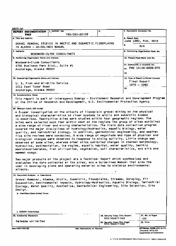
50272-101
REPORT DOCUMENTATION !-'~REPORT NO. I~ 3. Recipient"s Accession No.
PAGE FWS/OBS-80/09 4. Title and Subtitle 5. Report Date
June 1980, Pub. dete GRAVEL REMOVAL STUDIES IN ARCTIC AND SUBARCTIC FLOODPLAINS IN ALASKA- GUIDELINES MANUAL
.. N/A
7. Author(s) 8. Performinc Orpnlzatlon Rept. No.
WOODWARD-CLYDE CONSULTANTS 9. Performln& O .... nlntlon Name and Address 10. Project/Task/Work Unit No.
Woodwerd-Ciyde Consultents 11. Contnct(C) or Grant(G) No. 4791 Business Perk Blvd., Suite f1
Anchorege, Aleske 99503 (C) FWS 14-16-0008-970
(G)
12. SponsorinK Ora:anlutlon Name and Address 13. Type of Report & Period Covered
U. S. Fish end Wild! ife Service Fine! Report
1011 Eest Tudor Roed 1975 - 1980
Anchorege, Aleske 99503 14.
15. Supplementary Notes
This report is pert of Interagency Energy - Environment Reseerch end Development Progrem of the Office of Reseerch end Development, U.S. Environmentel Protection Agency
----- ----- ---·· 16. Abstract (Limit: 200 wordS)
A 5-yeer investigetion of the effects of floodplain grevel mining on .the physicel end biologicel charecteristics ·of river systems in arctic end subarctic Aleske is described. Twenty-five sites were studied within four geogrephic regions. The sites were selected such thet within eech of the regions the group of sites exhibited e wide renge of river end mining cherecteristics. The field date collection progrem covered the mejor disciplines of hydrology/hydreul ics, equetic biology, weter quel ity, end terrestriel biology. In eddition, geotechnicel _engineering, end aesthe-tics site reviews were conducted. A wide renge of megnitude end type of physical end bio!ogicel changes were observed in response to mining ectivity. Little chenge wes observed et some sites, whereas other sites exhibited changes in chennel morphology, hydraulics, sedimentetion, ice regime, equatic habitet, water quality, benthic mecroinvertebretes, fish uti lizetion, vegetetion, soil cherecteristics, end bird and memmel usege.
Two mejor products of the project ere a Technicel Report which synthesizes and evaluates the date collected at the sites, end 11 Guide! ines Menual thet eids the user in developing plans end opereting materiel sites to minimize environmentel effects. .
17. Document Analysis a. Descriptors
Greve! Remove!, Alaske, Arctic, Subarctic, Floodpleins, Streams, Scraping, Pit Excevation, Environmental impects, Hydrology-Hydreul ics, Aquetic Biology, Terrestriel Ecology, Water Quel ity, Aesthetics, Geotechnicel Engineering, Site Selection, Site Design.
b. Identifiers/Open-Ended Terms
c. COSATI Field/Group
lL Availability Statement 1!. Security Class (This Report) 21. No. of P88H
Unclessified 169 Releese unlimited --
20. rrnrl,i'~"i'IY'k•J'" .. ' 22. Price
(See ANSI-z39.18) s .. Instructions on Reverse OPTIONAL FORII 272 (4-7n (Formerly NTIS-35) Department of Commerce
• *U.S. GOVERNMENT PRINTING OFFICE: 198Q--699-278

REGIONAL OFFICE BIOLOGICAL SERVICES TEAMS
Region 1 Team Leader U.S. Fish and Wildlife Service Lloyd 500 Building, Suite 1692 500 N.E. Multnomah Street Portland, Oregon 97232 FTS: 429-6154 COMM: (503) 231-6154
Region2 Team Leader U.S. Fish and Wildlife Service P.O. Box 1306 Albuquerque, New Mexico 87103 FTS: 474-2971 COMM: (505) 766-1914
Region3 Team Leader U.S. Fish and Wildlife Service Federal Building, Fort Snelling Twin Cities, Minnesota 55111 FTS: 725-3593
. COMM: (612) 725-3510
Region4 Team Leader U.S. Fish and Wildlife Service 17 Executive Park Drive, N.W. P.O. Box 95067 Atlanta, Georgia 30347 FTS: 257-4457 COMM: (404) 881-4457
Regions Team Leader U.S. Fish and Wildlife Service One Gateway Center Suite700 Newton Corner, Massachusetts 02158 FTS: 829-9217 COMM: (617)965-5100, Ext. 217
Region6 Team Leader U.S. Fish and Wildlife Service P.O. Box 25486 Denver Federal Center Denver, Colorado 80225 FTS: 234-5588 COMM: (303) 234-5588
Alaska Area Office Team Leader U.S. Fish and Wildlife Service 1011 E. Tudor Road Anchorage, Alaska 99503 FTS: 3~150 ask for COM M: (907) 276-3800