Guidelines - Indiana University Bloomingtonuao/docs/standards/IU BIM Guidelines and Standards...The...
30
BIM Guidelines & Standards for Architects, Engineers, and Contractors Initiated: Sept. 10th, 2009 Revised: July 1st, 2015
Transcript of Guidelines - Indiana University Bloomingtonuao/docs/standards/IU BIM Guidelines and Standards...The...

BIM Guidelines
& Standards for Architects, Engineers, and Contractors
Initiated: Sept. 10th, 2009
Revised: July 1st, 2015

Acknowledgements
Indiana University is indebted to those many organizations that have helped pave the path for Owner organizations like ourselves in their development and improvement of Building Information Modeling (BIM) Guidelines, Standards, and Execution strategies. We wish to acknowledge that their commitment and progress has helped provide this BIM framework for Indiana University. We continue to hope that as we move forward in the use of BIM and IPD, that our progress and experiences fosters further assistance to others.
Special thanks and acknowledgement goes to:
• General Services Administration (GSA) – 2007 National 3D-4D BIM Program (link) • U.S Army Corps of Engineers – 2006 BIM Road Map (link) • NBIMS National BIM Standard – 3/2007 (link) • U.S Army Corps of Engineers - Construction Operations Building Information Exchange
(COBIE) - 8/2007 (link) • Triton College Building Information Modeling (BIM) Standards Model – 2005-2009 • State of Wisconsin Dept. of Administration – July 2009 BIM Guidelines and Standards • buildingSMART Alliance and CFTA (Campus FM Technology Association) – vital
organizations that foster collaboration and the sharing of BIM knowledge and expertise • SHP Leading Design – for their expertise and guidance in BIM and IPD

4/7/2015 INDIANA UNIVERSITY 1
Building Information Modeling (BIM) Guidelines and Standards for Architects, Engineers, and Contractors
This BIM Guideline and Standard applies to Indiana University A/E consultants for the following projects:
• Required on all construction (new and addition/alteration) with total project funding of $5M or greater, required on any project that involves a portion of a facility that has already been delivered with a BIM requirement. • Encouraged on all other projects. (The Indiana University goal is to have all IU projects using BIM in the future)
For more information and updates on Indiana University BIM guidelines and standards – please visit our website: http://www.iu.edu/~vpcpf/consultant-contractor/standards/bim-standards.shtml

4/7/2015 INDIANA UNIVERSITY 2
Table of Contents
SECTION 1: GENERAL REQUIREMENTS……………………………….……. ................................................... 3
SECTION 2: PROCESS……………………………………………. ....................................................................... 5
SECTION 3: DESIGN TEAM DELIVERABLE SCHEDULE AND MILESTONES ………… ............................. 7
SECTION 4: OBJECTIVES AND APPLICATION……………………………….…………………. .............................. 8
4.1 : PRE-DESIGN PHASE (CONCEPTUALIZATION)……………………………..………..…..……. 8
4.2 : SCHEMATIC DESIGN PHASE (CRITERIA DESIGN)…………….………………………………. 9
4.3 : DESIGN DEVELOPMENT PHASE (DETAILED DESIGN)……………………….…..………. 12
4.4: CONSTRUCTION DOCUMENTS PHASE …………...…………………………..….…..………. 18
4.5: BIDDING PHASE ……………………………..………………………………………………...……….. 19
4.6: CONSTRUCTION PHASE ………………………………………………..………………..…….……. 20
4.7: PROJECT CLOSE-OUT.…..……………………………………………………………….……….……. 23
4.8: PROJECT AS-BUILT AND RECORD DOCUMENT DELIVERABLE MATRIX ……….. 24
SECTION 5: OWNERSHIP AND RIGHTS OF DATA……………………………………………. ........................... 25
SECTION 6: TERMINOLOGY…………………………………………………………………………. ............................. 26

4/7/2015 INDIANA UNIVERSITY 3
1. General Requirements 1.1. Design Team Software Building information models shall be created to include all geometry, physical characteristics and product data needed to describe the design and construction work of a project. All drawings, schedules, simulations, and services required for assessment, review, bidding and construction shall be extractions from this model. The Design Team shall follow the guidelines and requirements detailed in this document for BIM related services. Deliverable requirements are as specified in the Indiana University professional services contract (deliverables sections) and the Indiana University document: “Deliverable Requirements for Construction Documents & Project Close-out Phases” located on the web for download at: http://www.indiana.edu/~uao/docs/standards/IU_as-built_cad_requirements.pdf
1.2. Civil Engineering Software Models shall be created that include all geometry, physical characteristics and product data needed to describe the design and construction work to within 5’ of building envelope. Drawings and schedules required for assessment, review, bidding and construction shall be extractions from this model. Software shall be capable of interfacing with The Design Teams BIM authored software. In all cases, model building and infrastructure systems to a level that allows the team to verify clearances, analyze conflicts/clashes and properly coordinate the work with all other aspects of the project. The Design Team shall follow the guidelines and requirements detailed in this document for BIM related services. Deliverable requirements are as specified in the Indiana University professional services contract (deliverables sections) and the Indiana University document: “Deliverable Requirements for the Construction Documents & Project Close-out Phases.”
1.3. BIM Authoring Software The Design Team is required to use parametric BIM Authoring software for Indiana University projects. The deliverable file format for all BIM project models is to be .RVT (Autodesk Revit).
1.4. Open Architecture for Interoperability Indiana University has adopted open architecture for data exchange. The Design Team is encouraged to use products based on or using open architecture for greatest interoperability between consultants and Indiana University.
1.5. Geo-referenced model The Design Team shall geo-reference site plans and building models to the following:
• Bloomington and Northwest (Gary) campuses - Indiana State Plane West, NAD 1983 – foot coordinate system and North American Datum of 1983 - GCS.
• Columbus, East (Richmond), IUPUI, Kokomo, South Bend, and Southeast (New Albany) – Indiana State Plane East, NAD 1983 – foot coordinate system and North American Datum of 1983 - GCS.

4/7/2015 INDIANA UNIVERSITY 4
1.6. Project collaboration tools The Design and Construction Team is required to use Indiana University’s electronic project collaboration environment – ProjectDox for document management and file sharing, reviewing tools, project communication, and a built-in .NWD viewer (Navisworks) for reviewing 3D BIM models (supports up to .NWD version 2014 at this time).

4/7/2015 INDIANA UNIVERSITY 5
2. Process 2.1. BIM Proficiency Matrix The Design Team shall submit to Indiana University upon request and ahead of contract award, a IU BIM Proficiency Matrix. The IU BIM Proficiency Matrix template is located on the web for download at: http://www.iu.edu/~vpcpf/consultant-contractor/standards/bim-standards.shtml. The IU BIM Proficiency Matrix will be reviewed by Indiana University to give IU an overview of the Consultant(s) BIM expertise and experience. The IU BIM Proficiency Matrix is scored by the Consultant (1 point per credit area) and should include examples of actual projects where BIM was applied. 3D CAD and SketchUp are not to be counted as BIM examples/expertise.
2.2. BIM Execution Plan The Design Team shall submit to Indiana University within thirty (30) days of contract award, a BIM Execution Plan. The BIM Execution Plan’s template is located on the web for download at: http://www.iu.edu/~vpcpf/consultant-contractor/standards/bim-standards.shtml. The BIM Execution Plan will be reviewed and approved by Indiana University within fourteen (14) days of it being submitted. The BIM Execution Plan shall identify the entire Design Team including all consulting engineers and specialty consultants. The BIM Execution Plan also should include roles and responsibilities of the contractor(s) even if that party has not yet been identified. The BIM Execution Plan will be a part of the final bid documents.
2.3. IPD (Integrated Project Delivery) Methodology Plan The Design Team shall submit to Indiana University within thirty (30) days of contract award, an IPD Methodology Plan. The IPD Methodology Plan’s template is located on the web for download at: http://www.iu.edu/~vpcpf/consultant-contractor/standards/bim-standards.shtml. The IPD Methodology Plan will be reviewed and approved by Indiana University within fourteen (14) days of it being submitted. The IPD Methodology Plan shall demonstrate a high level of integrated design while identifying project team members and how they will interact with each other during the project. This plan will include a critical path methodology on modeling procedures and model information validation. Examples of IPD Methodology plans are, but are not limited to: Reverse Phase Scheduling and Critical Path Modeling. The IPD Methodology Plan will be a part of the final bid documents.
2.4. Model quality The Design Team shall establish and use in-house modeling quality control guidelines and exchange protocols. Good BIM practices may include, but are not limited to:
• Use of element and component objects that embed the best practices of the firm. • Maintenance of parametric linkages within the model at all times. • The building envelope needs to be "air-tight" and correct to help support energy modeling
activities and simulations. • Use Indiana University defined nomenclature for objects and spaces – or if none exist then
Industry standards. • Use appropriate and interoperable viewing, checking, and output file formats.

4/7/2015 INDIANA UNIVERSITY 6
• Use appropriate phasing throughout the project to maintain Indiana University’s proper model nomenclature.
2.5. Energy requirements The Design Team shall work with IU to establish project specific energy goals and energy use targets. The Design Team shall also establish an energy modeling methodology that will be included within the BIM Execution Plan that will detail how energy modeling will be accomplished for the project. At a minimum, the required software to perform the energy modeling for the project shall be any software as listed acceptable by the US Department of Energy, Energy Efficiency and Renewable Energy. A list of approved software can be found at the following link: http://energy.gov/eere/buildings/qualified-software-calculating-commercial-building-tax-deductions
In addition to this list, the designer may also refer to http://energy.gov/eere/buildings/building-technologies-office , or use the following DOE 2 based software:
• Green Building Studios • Ecotect • eQuest
Local weather data shall be obtained from TMY2 or TMY3 weather data tables. Weather files can be downloaded from the National Renewable Energy Laboratory website at the following link: http://www.nrel.gov/gis/data.html

4/7/2015 INDIANA UNIVERSITY 7
3. Design Team Deliverable Schedule and Milestones The submittal schedule along with the milestones for any given project is listed below:
Milestone Deliverable Conceptualization Phase Architectural Massing Model
Preliminary Energy Model Spreadsheet
Schematic Design Phase Architectural Model Schematic Energy Model Initial Collision Report Square Foot Cost Analysis (upon request)
Design Development Architectural Model Detailed Energy Model MEP Model or Models Structural Model Discipline Collision Report System Cost Estimate Program Validation
Construction Documents Architectural Model MEP Model or Models Structural Model Pre-Bid Collision Report Quantity Estimate COBIE2 Design Data (worksheets 01-07)
The rest of the deliverables and milestones for the Design Team are shown later in the document.

4/7/2015 INDIANA UNIVERSITY 8
4. Objectives and Application 4.1. Pre-Design Phase (Conceptualization)
4.1.1. General The Design Team is encouraged to use electronic programming and planning tools that integrate into their BIM Authoring software to capture early cost, schedule and program information during this phase.
4.1.2. Topographic and Property Line Surveying Detailed requirements of what is to be included in surveying deliverables is managed by Indiana University staff in consultation with the Design Team on a project-by-project basis. Surveys shall be provided in electronic format and should include at minimum: 3D topographic information, paving and retaining walls. The file(s) shall be in a format that allows for importing into the Design Team’s BIM authoring software. Survey requirements are outlined in the Indiana University Site/Landscaping Standards: http://www.iu.edu/~vpcpf/consultant-contractor/standards/site-landscape.shtml
4.1.3. Energy Modeling Requirements
4.1.3.1. General The purpose of the preliminary (conceptualization) energy model is to narrow down design strategies from the multitude of design possibilities to those that are in line with and will achieve the projects energy goals and targets.
4.1.3.2. Simple Building Information Model (SBIM) The design team shall develop a simplified BIM model for use in preliminary energy modeling. This model shall define the building footprint and include all exterior walls. Interior spaces of similar use and occupancy shall be grouped into larger blocks or rooms, with interior walls limited to those separating areas of dissimilar use. All floors must be modeled. All roofs must be modeled. All rooms, or blocks of rooms, must be bounded. Fenestration shall be calculated as a percentage of floor area and need not be modeled.
4.1.3.3. Information Exchange Information that is developed in the SBIM should be formatted for a .GBXml export. This file standard is used by most energy modeling software or analysis software.
4.1.3.4. Comparative Design The purpose of these simulations is to inform early design decisions with reference to building envelope, lighting, domestic water, and HVAC systems. Multiple energy simulation iterations shall be performed by changing one component at a time and comparing those results to the results of other iterations in a “percent better” or “percent worse” scenario. Design components that are in line with the project energy goals and offer “percent better” results will then be developed further in the schematic (criteria) design phase.
4/7/2015 INDIANA UNIVERSITY 9
4.1.3.5. Energy Modeling Deliverables The Design Team shall submit to Indiana University, in spread sheet format, the list of design iterations and comparisons of the design iterations. The spread sheet should include columns for Peak Monthly Load, Peak Yearly Load, Total Yearly Load, and Total Yearly Energy Use by Source Type.
4.1.4. Existing Conditions The Design Team shall model all existing conditions needed to explain the extent of the construction work for alterations and additions projects. The extent of modeling beyond the affected areas and the level information to be included will be determined based on project needs. These requirements may be stated in the project program or discussed during the project kickoff meeting. The BIM Execution Plan should define the agreed upon scope of the modeling effort.
4.2. Schematic Design Phase (Criteria Design)
4.2.1. General Design Team may use any method to begin the design process but shall be using a BIM authored model(s) by completion of this phase. All information needed to describe the schematic design shall be graphically or alphanumerically included in and derived from these models. Indiana University expects the Design Team to use analysis tools, static images and interactive 3D to describe the design concepts. Deliverables are required as stated in Section 2.3.
4.2.2. Square Foot Cost Analysis The Design Team shall extract square foot information using BIM Authoring Software and other BIM integrated tools to support comparative costs analysis of options studied. Outputs shall be converted to spreadsheets and submitted as part of the design solution justification at end of this phase.
4.2.3. Energy Modeling Requirements
4.2.3.1. General The purpose of the schematic design (criteria design) energy model is to continue to refine design strategies and to calibrate the building’s energy performance.
4.2.3.2. Building Information Model The design team shall develop a BIM model for use in schematic energy modeling with the following criteria:
• The model shall define the building footprint and include all exterior walls. • The model shall define all interior walls, with all rooms modeled individually. • All fenestration shall be modeled. • All doors shall be modeled. • All overhangs, sun shades and roof monitors shall be modeled. • All floors must be modeled. • All roofs must be modeled. • All ceilings must be modeled. • All rooms must be bounded. • All room names and numbers must be defined and entered into the element properties.

4/7/2015 INDIANA UNIVERSITY 10
The following information shall also be incorporated into the energy model:
• Detailed electric and fuel rates as defined by the local service provider. • Building function and occupancy. • Building operating schedules. • Building lighting information in watts/ft2 and schedules. • Building HVAC equipment information (EER, COP, MBH, kW, tons, etc) and schedules. • Building plug load information (kW, Btuh) and schedules. • Building process load information (kW, Btuh) and schedules. • Building envelope construction components including U-values, SHGC, absorptivity, SRI value,
color, thickness, etc, as applicable to the component.
4.2.3.3. Software requirements The schematic model incorporating all of the components described above shall be exported using a .GBXml file for use in a DOE 2 based energy modeling software. See Section 2.4 for a list of software.
4.2.3.4. Energy Modeling Deliverables The design components that provide a “percent better” result as developed in the preliminary energy model shall now be modeled based on the schematic BIM model. Multiple iterations shall be performed and compared in order to ascertain the best design of envelope, lighting, domestic water, and HVAC system for the project to meet the projects energy goals and targets.
The Design Team shall submit to Indiana University, in spread sheet format, the list of design iterations and comparisons of the design iterations. The spread sheet should include columns for Peak Monthly Load, Peak Yearly Load, Total Yearly Load, and Total Yearly Energy Use by Source Type. Output format shall clearly communicate and be appropriate to project needs and submitted as part of the design solution justification at the end of this phase.
The results shall include, but are not limited to, the following:
• Annual and monthly energy usage broken down by component in kBtu, kBtu/ft2 and cost in dollars.
• Annual and monthly energy usage broken down by component in kWh or Therm. • Annual and monthly energy demand broken down by component in demand kW or demand
MBH.
4.2.4. Program and Space Validation The Design Team shall use the BIM Authoring software or other analysis tools to compare and validate stated program requirements (normally provided by Indiana University) with the actual design solution. The space validation shall be based on the Postsecondary Education Facilities Inventory and Classification Manual (FICM).
The following shall be developed automatically from the building information model:
• Assignable Areas (ASF) and Non-assignable Areas (NaSF) measured to inside face of wall objects
and designated boundaries of areas. • Gross Area (GSF) measured to the outside face of wall objects.

4/7/2015 INDIANA UNIVERSITY 11
4.2.6. Initial Collision Report
4.2.6.1. General The Design Team is to use automated conflict checking software for this phase of the work and shall be outlined in the BIM Execution Plan. The collision report should show any outstanding coordination issues between the Design Team members.
4.2.6.2. Level One Collisions Level One Collisions are reported collisions that are considered critical to the design and construction process. These collisions have been assigned the highest priority and should be rectified within the model as soon as possible:
• Mechanical Ductwork and Piping vs. Ceilings • Mechanical Ductwork and Piping vs. Rated Walls (For coordination of Dampers and other
mechanical equipment needs) • Mechanical Ductwork and Piping vs. Structure (Columns, Beams, Framing, etc.) • All Equipment and their applicable Clearances vs. Walls • All Equipment and their applicable Clearances vs. Structure • Mechanical Equipment and Fixtures vs. Electrical Equipment and Fixtures • Mechanical Ductwork and Piping vs. Plumbing Piping
4.2.6.3 Level Two Collisions Level Two Collisions are reported collisions that are considered important to the design and construction process. These collisions have been assigned a greater priority and should be rectified during project meetings during design:
• Casework vs. Electrical Fixtures and Devices • Furnishings vs. Electrical Fixtures and Devices • Structure (Columns, Beams, Framing, etc.) vs. Specialty Equipment • Structure (Columns, Beams, Framing, etc.) vs. Electrical Equipment, Fixtures and Devices • Ductwork and Piping vs. Electrical Equipment, Fixtures, and Devices • Ductwork vs. Floors
4.2.6.4. Level Three Collisions Level Three Collision are reported collisions that while considered important to the correctness of the model will generally be changing on a regular basis throughout the design and construction process. These collisions have been assigned a lower level of priority and should be rectified before the phase submission of the models:
• Casework vs. Walls • Plumbing Piping vs. Electrical Equipment, Fixtures, and Devices • Plumbing Piping vs. Mechanical Equipment, Fixtures, and Devices • ADA Clear Space Requirements vs. Doors, Fixtures, Walls, Structure

4/7/2015 INDIANA UNIVERSITY 12
4.2.6.5. All other Collisions While the above collisions have been assigned priorities other collisions will exist within the models. The collisions are not all ignorable nor should they be discarded. Some collisions will exist because the software available is not yet mature enough to support the modeling efforts. The intention should be to have a model that is as error and collision free as possible at each submission phase with documented proof that the design team addressed the prior collisions above.
4.2.7. Planning Tools The Design Team is encouraged to use electronic programming and planning tools that integrate into BIM Authoring software to continue project development at this phase.
4.3. Design Development Phase (Detailed Design)
4.3.1. General The Design Team shall continue development of their Building Information Model. Parametric links shall be maintained within the models to enable automatic generation of all plans, sections, elevations, custom details and schedules as well as 3D views.. All information needed to describe the “detailed design” shall be graphically or alphanumerically included in and derived from these models only, except for the Specifications. Documentation of the models shall not happen outside of the BIM Authoring software. The quality of the models shall be as stated in Section 2.3.
4.3.2. Architectural Systems The model should include the following architectural elements to a level that defines the design intent and accurately represents the design solution:
• Architectural Site plan (also see Civil Engineering section below)
o Paving, grades, sidewalks, curbs, gutters, site amenities and other elements typically included on enlarged scale site drawings in building vicinity.
• Existing conditions to the extent required by 3.1.4. • Demolished items to the extent required by 3.1.4. • New interior and exterior walls including but not limited to:
o Doors, windows, openings o Interior and exterior soffits, overhangs, sun control elements o Parapets, screening elements o Architectural precast All finishes need to be included within the wall type regardless of the thickness of the finish
• Floor, ceiling and roof systems including but not limited to: o Appropriate structural items listed below if not provided by the structural engineer and
integrated into the architectural model for coordination and document generation. o Insulation, ceiling systems, and floor are to be included. o Roof, floor and ceiling slopes, if needed, shall be modeled. o Soffits, openings, and accessories will also be modeled.
• Elevators, stairs, and ramps (including railing systems) • Casework, shelving, and other interior architectural elements • Furnishings, fixtures, and equipment (if not provided by others and integrated into the
architectural model for coordination and document generation.)
4/7/2015 INDIANA UNIVERSITY 13
o Furniture (Fixed and Loose) o Furniture Systems o Specialty equipment (food service, medical, etc) o Model mechanical, electrical and plumbing items that require architectural space
(toilets/sinks/etc), require color/finish selection (louvers, diffusers, etc.) or affect 3D visualization (lighting fixtures) unless provided by engineers.
• Clearance zones for access, door swings, service space requirements, gauge reading, and other operational clearance must be modeled as part of all equipment and checked for conflicts with other elements. These clearance zones should be modeled as invisible solids within the object.
The detail and responsibility to fulfill the above modeling requirements should be addressed fully within the BIM Execution Plan.
4.3.3 Structural Engineering The model should include the following structural elements:
• Foundations such as:
o Spread Foundations o Caisson Foundations o Pile Foundations o Mat Foundations o Load-bearing Wall Foundations
• Framing such as: o Steel Columns (with correct shape and size) o Steel Floor C-Joists o Open Web Joists o Joist Girders o Steel Beams (with correct shape and size) o Precast Concrete Elements (Hollow Core Plank may be modeled as a slab unless the
hollow core is being used for mechanical systems and coordination with those systems needs to occur)
o Cast-In-Place Concrete Elements o Floors including overall extents and openings o Model overall thickness of wood floor systems o Wood Posts/Column o All other Joists o Wood Trusses o Solid Wood or Laminated Beams
• Wall Types including openings o Load Bearing Walls – for calculations only (Masonry, Concrete, Cold-Formed Steel, and
Wood) o Model overall thickness of Cold-Formed Steel and Wood Stud walls (individual members
may be modeled at the Design Team’s option) o Structural Foundation Walls including brick ledges
• These items may be modeled at the Design Team’s option: o Steel reinforcing in concrete o Embeds in concrete
• Miscellaneous Steel
4/7/2015 INDIANA UNIVERSITY 14
o Angles for openings, deck bearing, etc. o Channels for mechanical units needed for coordination reviews between structural and
mechanical o Lintels (unless considered a major member)
The detail and responsibility to fulfill the above modeling requirements should be addressed fully within the BIM Execution Plan.
4.3.4. HVAC Systems The model should include the following HVAC elements at a minimum:
• Equipment
o Fans, VAV’s, compressors, chillers, cooling towers, air handlers etc. • Distribution
o Supply, return, exhaust, relief and outside air ductwork modeled to outside face dimension or duct insulation (whichever is greater)
o Duct Joints o Diffusers, grilles, louvers, hoods, radiant panels, perimeter units, wall units
• Pipes larger than 3/4” diameter, include any insulation in model. Unless otherwise noted and approved by the BIM Execution Plan.
• Clearance zones for access, door swings, service space requirements, gauge reading, and other operational clearance must be modeled as part of the HVAC equipment and checked for conflicts with other elements. These clearance zones should be modeled as invisible solids within the object.
The detail and responsibility to fulfill the above modeling requirements should be addressed fully within the BIM Execution Plan.
4.3.5. Electrical systems The model should include the following electrical elements at a minimum:
• Power and Telecommunications
o Interior and exterior transformers, emergency generators, and other equipment o Main and distribution panels and switchgear including access clearances o Main IDF’s o Feeders and conduit larger than 3/4”diameter. Unless otherwise noted and approved by the BIM
Execution Plan. o Outlets, switches, junction boxes
• Lighting o Permanently mounted lighting fixtures (moveable, plug-in fixtures need not be modeled
as part of the electrical package unless needed for plug load calculations or for estimating purposes within a loose furnishings package. Should be discussed and agreed upon within the BIM Execution Plan)
o Lighting Controls o Switches o Junction Boxes
• Fire Alarm and Security Systems
4/7/2015 INDIANA UNIVERSITY 15
o Input devices o Notification devices o Associated equipment and access clearances o Permanently mounted fixtures
• Building Controls • Clearance zones for access, door swings, service space requirements, gauge reading, valve
clearances and other operational clearance must be modeled as part of the electrical equipment for collision checking. These clearance zones should be modeled as invisible solids within the object.
The detail and responsibility to fulfill the above modeling requirements should be addressed fully within the BIM Execution Plan.
4.3.6. Plumbing and Fire Protection The model should include the following plumbing and fire protection elements at a minimum:
• Waste and Vent Piping sized at and over 3/4” diameter, includes any insulation in model. Unless
otherwise noted by the BIM Execution Plan. o Roof and floor drains, leaders, sumps, grease interceptors, tanks, water treatments and
other major items. • Supply Piping larger than 3/4” diameter, includes any insulation in model. Unless otherwise noted
and approved by the BIM Execution Plan. o Domestic Booster Pumps
• Fixtures: sinks, toilet fixtures, water tanks, floor sinks • Fire protection
o Sprinkler lines larger than 3/4”diameter o Sprinkler heads, Fire Protection Pumps o Stand pipes, wall hydrants, fire department connections, risers, including valve
clearances • Clearance zones for access, service space requirements, gauge reading, valve clearances and
other operational clearance must be modeled as part of the plumbing and fire protections system and checked for conflicts with other elements. These clearance zones should be modeled as invisible solids within the object.
The detail and responsibility to fulfill the above modeling requirements should be addressed fully within the BIM Execution Plan.
4.3.7. Specialty Consultants The model should include the following specialty consultant elements to correct size and location:
• Equipment provided or specified by said consultant • Rough-in connection points for power, data, communications, water service and waste, gas,
steam, or other needed utilities. • Extent of specialty consultant modeling shall be coordinated with the Design Team and
described in the BIM Execution Plan.

4/7/2015 INDIANA UNIVERSITY 16
• Clearance zones for access, doors swings, service space requirements, controls, gauge reading, and other operational clearance must be modeled as part of the equipment and checked for conflicts with other elements.
Some of the above items may occur in the previously mentioned disciplines. The responsible party should be discussed within the BIM Execution Plan.
4.3.8. Civil Engineering If a Civil BIM model is used it should include the following civil engineering elements at a minimum:
• Topography – 3D terrain of all site work as designed, including retaining walls. This model
should include the site and surrounding areas that contribute to the site’s drainage system or otherwise impact on the site. In most cases this will require that adjacent roadways be modeled.
• Landscaping elements: planting areas, such as raised planting beds and berms, parking islands, pools/ponds/other water features, terraces and other items not included elsewhere in the model.
• Stormwater management structures, pump stations, fueling systems, manholes and other major items that impact on the overall project understanding or which may become project design constraints. All items must be geo-referenced such that all elements can be viewed as an overlay in the building information model or Indiana University’s GIS system correctly positioned in the correct location, at all times.
4.3.9. Energy modeling
4.3.9.1 General The Design Development phase energy model shall build upon the model developed in the Schematic Design phase. This energy model shall be complete enough to use for additional submissions, such as LEED EA Credit 1 calculations, should the building apply for LEED certification. This model shall be detailed and finalized enough to use as an indicator of approximate building energy use after occupancy. This model shall also serve as a baseline for future comparisons. After building completion and occupancy of a minimum of one year, actual building performance shall be evaluated against this model. This model shall be used as a tool to facilitate post-occupancy commissioning should discrepancies between modeled and actual energy use arise. Caution is advised in this, as deviations from design in weather, occupancy, plug loads, schedules, electric and fuel costs, etc. will affect actual energy use, and these factors must be taken into account.
4.3.9.2 Additional Modeling Requirements In addition to the items included and submitted in the schematic design phase, the design development model shall include the following:
• Energy Conservation Measures (ECMs). ECMs shall be used to evaluate control strategies and
additional components for energy savings, life cycle cost (LCC) and return on investment (ROI) costs.
4/7/2015 INDIANA UNIVERSITY 17
4.3.10. Discipline Collision Reports See Section 4.2.6
4.3.11. Program and Space Validation The Design Team shall use the methodology described in section 4.2.4 to reconfirm that program requirements are met.
4.3.12. Other analysis and checking tools The Design Team is encouraged to analyze the design using software that interacts with the model in order to refine load calculations, daylighting, natural ventilation, acoustics, code issues, and design issues.
4.3.13. Systems Cost Estimating The Design Team shall extract square foot and system information using BIM Authoring Software and other BIM integrated tools to support comparative costs analysis of options studied. Outputs shall be converted to spreadsheets and submitted as part of the deliverable at end of this phase.

4/7/2015 INDIANA UNIVERSITY 18
4.4. Construction Documents Phase
4.4.1. General The Design Team shall continue development of the models created in the Design Development Phase. Parametric links should be maintained within the respective models to enable automatic generation of all plans, sections, elevations, custom details, schedules and 3D views. All information needed to describe the “Execution documents” shall be graphically or alphanumerically included in and derived from these models only. Specifications are not required to be linked within the models. Model quality shall be as stated in Section 2.3.
4.4.2. Pre-Bid Collision Reports See section 4.2.6. Submit at 95% Construction Document Submittals
4.4.3. Program and Space Validation The Design Team shall use the methodology described in section 4.2.4 to reconfirm that program requirements are met.
4.4.4. Other analysis and checking tools The Design Team is encouraged to analyze the design using software that interacts with the model in order to refine load calculations, daylighting, natural ventilation, acoustics, code issues and design issues.
4.4.5. Quantity Cost Estimating The Design Team shall extract square quantity takeoff information using BIM Authoring Software and other BIM integrated tools to support comparative costs analysis of options studied. Outputs shall be converted to spreadsheets and submitted as part of the design solution justification at end of this phase.

7/2/2012 INDIANA UNIVERSITY 20
4.4.6 COBIE Design Data All named products and equipment appearing in design schedules shall be listed in the Components Table. The designer shall ensure that the list of equipment provided in the COBIE "Component" worksheet includes all equipment specifically identified on the design drawings or BIM model. The following worksheets shall be provided:
(1) Contact - Project team members (2) Facility - Facility(ies) referenced in the file (3) Floor - Description of vertical levels (4) Space - Spaces referenced in a project (5) System - Systems referenced in a project (6) Register - Material/equipment/etc. types (submittal register) (7) Component - Individually named materials and equipment
The COBIE spreadsheet and information on how to use COBIE may be found at: http://www.wbdg.org/pdfs/cobie_spreadsheet.pdf and http://www.wbdg.org/resources/cobie.php?r=om
4.5. Bidding Phase
4.5.1 General The Design Team shall update the models with all addendum, accepted alternates and/or value enhancement proposals.
4.5.3. Contractor Bidding Contractors who are bidding on this project are to review the BIM Execution Plan, the IPD Methodology Plan, and the BUILDING INFORMATION MODELING (BIM) GUIDELINES and STANDARDS for ARCHITECTS, ENGINEERS, and CONTRACTORS before bidding. Contractor will follow the guidelines and requirements as set forth by the BIM Execution Plan and the IPD Methodology Plan.
4.5.4. IU BIM Proficiency Matrix Interested Contractors shall submit to Indiana University at the point of bid submittal, a IU BIM Proficiency Matrix. The IU BIM Proficiency Matrix template is located on the web for download at: http://www.iu.edu/~vpcpf/consultant-contractor/standards/bim-standards.shtml . The IU BIM Proficiency Matrix will be reviewed by Indiana University to give IU an overview of the Contractor(s) BIM expertise and experience. The IU BIM Proficiency Matrix is scored by the Contractor (1 point per credit area) and should include examples of actual projects where BIM was applied. 3D CAD and SketchUp are not to be counted as BIM examples/expertise.
4.5.4. Construction Docs Deliverable Ten days after the project is awarded for construction, the Design Team shall submit to the University Architect’s Office one set of the Construction Document Deliverables. See specific requirements in this document.
7/2/2012 INDIANA UNIVERSITY 20
4.6. Construction Phase
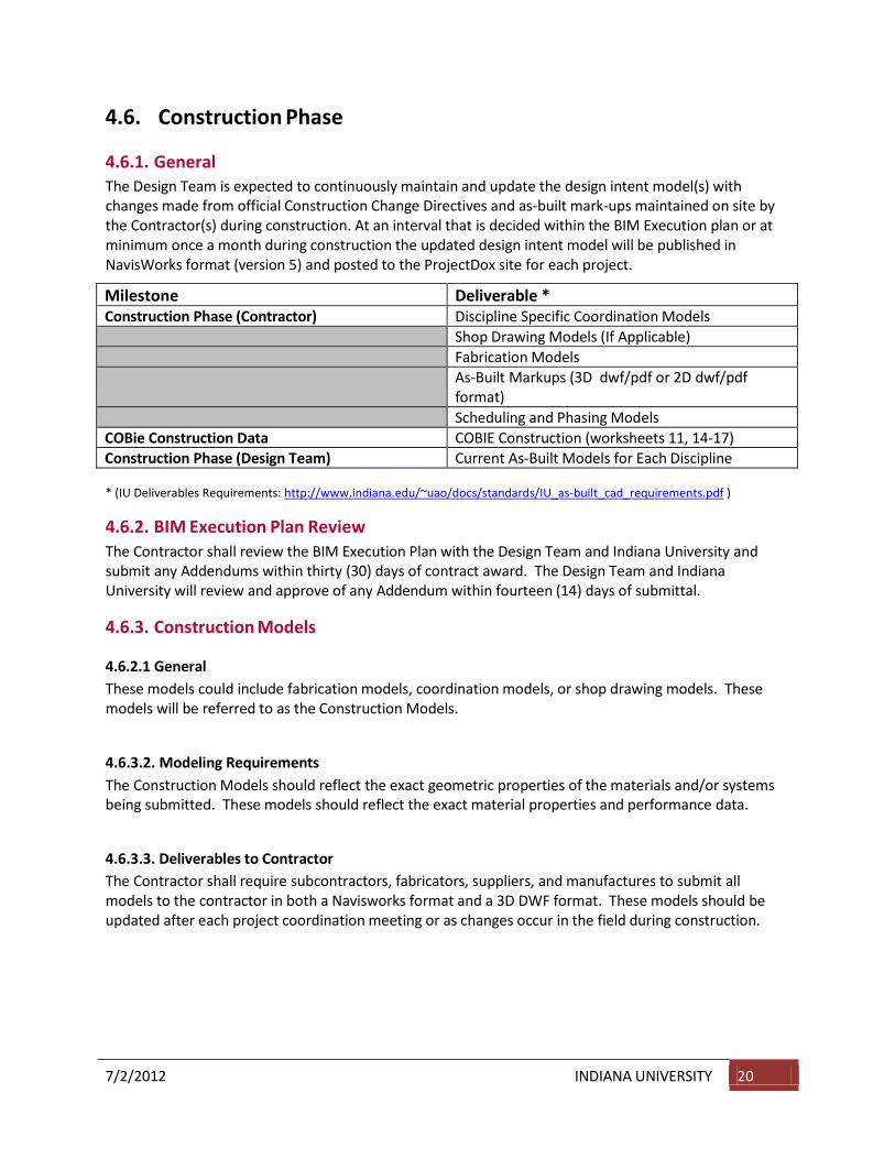
4.6.1. General The Design Team is expected to continuously maintain and update the design intent model(s) with changes made from official Construction Change Directives and as-built mark-ups maintained on site by the Contractor(s) during construction. At an interval that is decided within the BIM Execution plan or at minimum once a month during construction the updated design intent model will be published in NavisWorks format (version 5) and posted to the ProjectDox site for each project.
Milestone Deliverable * Construction Phase (Contractor) Discipline Specific Coordination Models
Shop Drawing Models (If Applicable) Fabrication Models As-Built Markups (3D dwf/pdf or 2D dwf/pdf
format) Scheduling and Phasing Models
COBie Construction Data COBIE Construction (worksheets 11, 14-17) Construction Phase (Design Team) Current As-Built Models for Each Discipline * (IU Deliverables Requirements: http://www.indiana.edu/~uao/docs/standards/IU_as-built_cad_requirements.pdf )
4.6.2. BIM Execution Plan Review The Contractor shall review the BIM Execution Plan with the Design Team and Indiana University and submit any Addendums within thirty (30) days of contract award. The Design Team and Indiana University will review and approve of any Addendum within fourteen (14) days of submittal.
4.6.3. Construction Models
4.6.2.1 General These models could include fabrication models, coordination models, or shop drawing models. These models will be referred to as the Construction Models.
4.6.3.2. Modeling Requirements The Construction Models should reflect the exact geometric properties of the materials and/or systems being submitted. These models should reflect the exact material properties and performance data.
4.6.3.3. Deliverables to Contractor The Contractor shall require subcontractors, fabricators, suppliers, and manufactures to submit all models to the contractor in both a Navisworks format and a 3D DWF format. These models should be updated after each project coordination meeting or as changes occur in the field during construction.

7/2/2012 INDIANA UNIVERSITY 21
4.6.3.4. COBIE Construction Data The Contractor shall submit to the Owner and Architect of Record, one copy in Excel format (.xls) for the COBie data set listed below.
This data set shall be an update to the designer’s COBIE worksheets. This set shall be provided prior to final payment application. The following worksheets shall be provided:
(11) Document - Documents referenced in this file (14) Installation - Location and serial no. of installed components (15) Manual – Manufacturer provided operation, maintenance, and installation manuals for sets of/or components (16) Warranty - Warranty information for sets of/or components (17) Spare - Spare/parts reordering info for sets of/or components
4.6.4. Coordination Meetings
4.6.4.1. General The contractor shall submit a plan to the Owner for review, prior to the start of construction that outlines the process for concurrent as-built documentation. Concurrency is mandated. Methods for recording as-built information are left to the discretion of the contractor. Potential options include traditional methods, and/or periodic laser scanning of completed or partially completed primary systems coordinated with the sequence of construction. Primary systems fall into two categories:
Primary Architectural Systems include, but may not be limited to: Partition systems with structure, flooring systems, major HVAC, piping, sewerage and /or conduit systems, partition systems with bulkheads, partition systems with expansion control, vertical transportation systems with primary engineering systems, millwork and casework systems with power and data outlets, horizontal ceiling systems with window openings, bulkheads, partitions, lighting, fire protection and HVAC outlet locations, exterior skin systems with window openings, structure, roof edge conditions, parapets, roof penetrations, and equipment locations.
Primary Engineering Systems include, but may not be limited to: structural framing, primary HVAC duct runs, primary fire protection main runs, primary electrical conduits (larger than ¾” diameter), ceiling grid layouts, primary data, audio/visual, security and communication distribution systems (cable trays, etc).
4.6.4.2. Projects without active REVIT Models at the start of construction. If REVIT models are not provided by the A/E at the start of construction, the contractor shall develop REVIT models for use during construction according to the program requirement as established in the bid documents. The contractor shall coordinate REVIT model source with the Owner prior to selection. The purpose of this model shall be to house the pertinent data as established by the bid documents and program, necessary to support future facility management objectives. Additionally these models shall be the repository of final “as-built” data incorporated either by concurrent laser scanning and/or traditional recording methods for as-built conditions.

7/2/2012 INDIANA UNIVERSITY 22
4.6.4.3. Projects with active REVIT Model at the start of construction. If REVIT models are provided by the A/E at the start of construction, the contractor shall use those models in support of the objectives noted in 4.6.4.2
4.6.4.4. Coordination with Design Team and Owner On no less than a biweekly basis the contractor shall include the project model manager, (architect’s or other) in a coordination established for the purpose of assessing and / or executing FM data transfers from the construction process into the REVIT model. The data transfer shall be coordinated with the Owner representative and the architect’s model manager (when feasible) and be based on the FM objectives as defined in the BIM Execution Plan and project program.
4.6.4.5. Milestone Deliverables Navisworks files should be created at all critical coordination milestones. This record format will document a coordinated section of the model, either by area of the building or between specific critical trades. The Collision report showing all applicable collisions as either Approved or Resolved along with the Navisworks file shall be uploaded together to ProjectDox. A text document shall also be uploaded which describes and references the approved coordination NWD File with respect to what has and has not been coordinated.
4.6.5. Collision Reports The Contractor is to use Navisworks Manage software for collision reporting. Collision reports from Navisworks should be published weekly in a standard XML, HTML, or Text format as created by Navisworks. These reports shall include the following information at a minimum:
• Description of Collision Report • Date of Collision Report Run • List of all Collisions detected, their status, and their proposed solution.
4.6.6. Concurrent As-Builts
4.6.6.1. General The contractor shall submit a plan to the Owner for review, prior to the start of construction that outlines the process for concurrent as-built documentation. Concurrency is mandated. Methods for recording as-built information are left to the discretion of the contractor. Potential options include traditional methods, and/or periodic laser scanning of completed or partially completed primary systems coordinated with the sequence of construction. Primary systems include, but may not be limited to: structural framing, primary HVAC duct runs, primary fire protection main runs, primary electrical conduits (larger than ¾” diameter), ceiling grids layouts.
4.6.6.2. Scheduling The sequence of concurrent as-builts shall be recorded in the contractor’s project schedule as a line item event.
4.6.7. Commissioning Requirements When commissioning is used on a project, commissioning data including but not limited to design intent, performance criteria and operations data shall be recorded and/or linked to the REVIT model as commissioning occurs throughout the project. Commissioning requirements shall be coordinated with the minimum LEED Silver requirements of the Owner. It shall be the contractor’s responsibility to

7/2/2012 INDIANA UNIVERSITY 23
coordinate the information sources and integrate this information into the REVIT model for transfer at the completion of the project.
4.7. Project Close-out
4.7.1. Design Team As-Builts The Design Team shall update their respective models with contractor recorded changes (Record Documents), and republish record documents in paper, .dwg and .pdf formats. They must also submit full Revit model(s) with all needed objects and reference drawings, in original authored software. The Design Team is required to submit all per Indiana University professional services contract (deliverables sections) and the Indiana University Deliverables Requirements for Construction Documents and As-built Record Documents standard (most recent version) prior to final payment. Access this standard here: http://www.indiana.edu/~uao/docs/standards/IU_as-built_cad_requirements.pdf .
4.7.2. Contractor Record Documents The contractor shall submit their record documents as outlined in the Indiana University Deliverables Requirements for Construction Documents and As-built Record Documents standard (most recent version) at substantial completion. Access this standard here: http://www.indiana.edu/~uao/docs/standards/IU_as-built_cad_requirements.pdf .
4.7.3. O&M (Operations & Maintenance) Manuals The contractor shall submit the following information to Indiana University – two paper copies in binders of the O&M Manuals along with the Construction Operations Building Information Exchange (COBie) format: (1) the make, model and serial number of each piece of installed equipment, (2) the location of any equipment installed in the building, and (3) manufacturer’s documents including cut sheets, installation instructions, and recommend maintenance tasks, testing or other reports. An electronic format of the O&M manuals shall also be submitted along with the paper copies, the format shall be color PDF and native Excel files (at substantial completion).

7/2/2012 INDIANA UNIVERSITY 24
4.8. Project As-Built and Record Document Deliverable Matrix Refer: http://www.indiana.edu/~uao/docs/standards/IU_as-built_cad_requirements.pdf .
5. Ownership and Rights of Data Indiana University has ownership of all CAD files, BIM Models, and Facility Data developed for the Project. Indiana University may make use of this data following any deliverable.

7/2/2012 INDIANA UNIVERSITY 25
6. Terminology A As-Built Documents
As-built documents are the collection of paper drawings or electronic drawings that typically reside in the contractor’s onsite trailer that contain mark-ups, annotations, and comments about changes that have been made to the contract documents during the construction phase.
As-Built Model Design Intent Models that have been updated throughout the construction process. These changes and updates have been communicated from the Contractor to the Design Team through the comments, annotations, and mark-ups from the As-Built Documents. These typically, but not always, are discipline specific models.
B BIM Execution Plan (BEP)
A plan that is created from Indiana Universities BIM Execution Plan Template that is to be submitted thirty (30) days after contract award. The BEP helps to define roles and responsibilities within a project team.
BIM Proficiency Matrix (BPM) A matrix designed to measure the expertise of a firm as it relates to using a BIM processes on projects. It will be used as one of the many criteria during the selection process.
C C.O.B.I.E. – Construction Operations Building Information Exchange
C.O.B.I.E. is a standard of information exchange that allows information to be captured during design and construction in a format that can be used during the operations of a building once completed.
Critical Path Modeling Critical Path Modeling is a method of demonstrating Integrated Project Delivery. It sets a plan within the design team that accounts for the activities of each discipline and how they interact with each other. It builds upon a critical path method for those activities, and allows the project team to schedule a complete project.
D Design Team
The Design Team is considered to be the Architect and all of the consultants that provide design services for a project. These design services can be rendered at any time during the project.
DOE2 – Department of Energy Version 2 DOE2 is a file type that is an open file format. This file format is used by most energy modeling software. It is also an approved file type for LEED simulations.

7/2/2012 INDIANA UNIVERSITY 26
.DWF
.DWG
F
.DWF is a file type that was developed by Autodesk to be locked file for drawing sheets and model data. It can be used as a file transfer for estimating data, markups, and other third party software. It can be a combination of 3D and 2D information within the same file.
.DWG is a native AutoCAD file format. It is a widely used file format for exchanging drawing information and 3D information to different programs. While not a database file type, it still has lots of uses for exchanging information.
FICM – Post Secondary Facilities Inventory and Classification Manual FICM is standard that describes practices for initiating, conducting, reporting, and maintaining an institutional facilities inventory.
G .GBxml
I
A .GBxml file is a Green Building file type. It is used to run simulations through energy modeling software. It is a widely accepted file format for those types of software.
IPD – Integrated Project Delivery IPD describes a contractual relationship between Owner, Architect, and Contractor. It is a project delivery method that integrates people, systems, business structure and practices into a process that collaboratively harness the talents and insights of all participants to optimize project results, increase value to the owner, reduce waste, and maximize efficiency through all phases of design, fabrication, and construction.
IPD Methodology IPD Methodology is a concept that uses methods from the IPD contracts, but does not have the contracts actually in place. It idealizes the concepts of integration of all team members to try and benefit the entire project.
IPD Methodology Plan The IPD Methodology Plan is a declaration of how the project team will achieve the goals of an IPD Methodology. The plan can have several components. Two examples of an IPD Methodology Plan are: The completion of a Reverse Phase Schedule and Critical Path Modeling.
L LEED
The Leadership in Energy and Environmental Design (LEED) Green Building Rating System is a suite of standards for environmentally sustainable construction. Based on a point system, a building or project, can achieve different ratings based on the performance of the design, the construction, and/or the operation.

7/2/2012 INDIANA UNIVERSITY 27
N Navisworks
Navisworks is software that allows for the viewing of multiple model formats. This ability to “view” these files also allows for Navisworks to simulate the interaction between model files. That includes collision reporting, time lining, and coordination.
.NWC
.NWD
An .NWC file is a Navisworks Cache File that is used by Navisworks to quickly read many other file types. All linked files in Navisworks have an .NWC file created automatically. In addition, Revit will export directly to the very small file type of .NWC for quick access by Navisworks.
A much larger file than the .NWC, the .NWD file shows a snapshot in time of a Navisworks file. No linked files exist but all geometry is included.
.NWF
O
The .NWF file is a native Navisworks file which has all linked files, clashes, markups, animations, schedules, etc.
Open Architecture Open Architecture is a concept of creating a framework that helps to describe a common set of rules for how a project is created. This includes what types of software, the interoperability of the information, and how the participants interact with each other. This is different than open standards because it promotes progress without anchoring forward thinkers to a rigid standard.
Owner’s Architectural Floor Plans – Interim Record Documents
A complete current electronic CAD set of Owner’s Architectural floor plan drawings with room names, room numbers, and room square footages indicated. The Owner’s Representative shall not be relieved of responsibility when files are delivered if the files do not meet established requirements or are defective. Indiana University shall verify all files and the Owner’s Representative shall be notified of acceptance. These are to be submitted 3 months prior to Substantial Completion.
P Phases
The phases of a project can be describe in two different ways as the adoption of IPD terminology starts to penetrate the BIM Execution Plan and the IPD Methodology Plan. Below is a list of the traditional names followed by the IPD name:
Pre-Design/Conceptualization Phase Schematic Design/Criteria Design Phase Design Development/Detailed Design Phase Construction Documents/Implementation Phase

7/2/2012 INDIANA UNIVERSITY 30
R Record Drawing
The production of Record Drawings is the capturing of the As-Built Document’s annotation, comments, and mark-ups in a drawing format only. This does not typically include the updating of any models.
Reverse Phase Scheduling
Reverse Phase Scheduling Is a method of demonstrating Integrated Project Delivery. It sets a plan within the design team that accounts for the activities of each discipline and how they interact with each other. It uses the completion date as a point to work backward from to schedule all of the project’s activities.
.RVT
S
An .RVT file is a native REVIT file type. It is also the deliverable file format for all projects. This includes all of the Design Team’s models.
SBIM – Simple Building Information Modeling SBIM is a concept of producing a “light” model that can be used for simulating the building’s performance very early within the design process. SBIM is the process of modeling only the exterior envelope, and the interior volumes to produce a lean model that energy modeling software can use easily.
T Telecommunications Drawings – Interim As-Built Documents
A complete current electronic CAD and PDF set of as-built Telecommunication drawing for Indiana University use in coordinating selection and procurement of telecommunications/data equipment.
TMY2/TMY3
The TMY2/3 file format is a Typical Meteorological Year file. It is used in conjunction with a .GBxml file to create energy simulations.