Guidelines in Pulsation Studies for … IN PULSATION STUDIES FOR RECIPROCATING COMPRESSORS Brian C....
11
1 Copyright © 2002 by ASME Proceedings of IPC’02 4th International Pipeline Conference September 29 - October 3, 2002, Calgary, Canada IPC02-27421 GUIDELINES IN PULSATION STUDIES FOR RECIPROCATING COMPRESSORS Brian C. Howes, M.Sc., P.Eng. Shelley D. Greenfield, P.Eng. ABSTRACT While new gas compression in pipeline service tends to be dominated by centrifugal machines, reciprocating compressors still have a significant place in the industry. Specific dynamic design is required to ensure reliable and efficient operation of all reciprocating compressor installations. This requirement is particularly significant in pipeline installations, because the compressor is intended to be in service for many years, and because high efficiency is important for economic reasons. It is widely recognized that the design of these types of installations should include a “pulsation study”. A pulsation study involves analysis of the proposed installation to predict pulsation, vibration, and stress levels. Further, a pulsation vibration control scheme is developed as part of the overall design. The objective is to ensure that predicted pulsation and vibration levels meet guidelines while limiting associated pressure drops and horsepower losses to acceptable levels. Various guidelines have been used in these studies, but the most commonly used standards are in API 618. While this standard was not originally intended for pipeline service, in reality it represents the best design standard available for high specification reciprocating compressor installations in any application. Recently, work has been done to upgrade the API 618 design standard. One of the changes in the proposed new 5 th edition is the addition of unbalanced force guidelines to the existing pressure pulsation guidelines. Much discussion occurred regarding the need for and the advisability of making the addition. Real examples show designs in which a reduction of pressure pulsation is accompanied by an increase in unbalanced forces, illustrating the need for an unbalanced force guideline. It is also shown that problems can occur due to unbalanced forces in parts of the piping system not currently addressed by the pulsation guidelines in API 618. The paper compares the current 4 th Edition versus the draft 5 th Edition. Comments are made on the applicability of the various guidelines. While API 618 is the best available design document, the addition of force guidelines will help API 618 do a better job for industry. INTRODUCTION While new gas compression in pipeline service tends to be dominated by centrifugal machines, reciprocating compressors still have a significant place in the industry. Depending on the specific application there are advantages and disadvantages to using each type of compressor. Some of these are briefly discussed in this paper. For installations where reciprocating compressors are used, detailed dynamic design is usually required to ensure a successful installation. Of the various design requirements discussed in this paper, pulsation control is one area where it may be difficult to find applicable guidelines or standards. The pulsation control section of API (American Petroleum Institute) 618 is most commonly used for these types of studies. While API 618 standard represents the best design standard available for high specification reciprocating compressor installations in any application, it falls short in some areas. Some of the recent work done to upgrade API 618, and other design guidelines not covered in the standard are discussed here. NOMENCLATURE Acoustical/acoustics – in this paper refers to the pressure fluctuations in the compressor piping system, not noise. http://www.BetaMachinery.com
Transcript of Guidelines in Pulsation Studies for … IN PULSATION STUDIES FOR RECIPROCATING COMPRESSORS Brian C....

1 Copyright © 2002 by ASME
Proceedings of IPC’024th International Pipeline Conference
September 29 - October 3, 2002, Calgary, Canada
IPC02-27421
GUIDELINES IN PULSATION STUDIES FOR RECIPROCATING COMPRESSORS
Brian C. Howes, M.Sc., P.Eng. Shelley D. Greenfield, P.Eng.
ABSTRACTWhile new gas compression in pipeline service tends to be
dominated by centrifugal machines, reciprocating compressorsstill have a significant place in the industry.
Specific dynamic design is required to ensure reliable andefficient operation of all reciprocating compressor installations.This requirement is particularly significant in pipelineinstallations, because the compressor is intended to be inservice for many years, and because high efficiency isimportant for economic reasons.
It is widely recognized that the design of these types ofinstallations should include a “pulsation study”. A pulsationstudy involves analysis of the proposed installation to predictpulsation, vibration, and stress levels. Further, a pulsationvibration control scheme is developed as part of the overalldesign. The objective is to ensure that predicted pulsation andvibration levels meet guidelines while limiting associatedpressure drops and horsepower losses to acceptable levels.
Various guidelines have been used in these studies, but themost commonly used standards are in API 618. While thisstandard was not originally intended for pipeline service, inreality it represents the best design standard available for highspecification reciprocating compressor installations in anyapplication.
Recently, work has been done to upgrade the API 618design standard. One of the changes in the proposed new 5th
edition is the addition of unbalanced force guidelines to theexisting pressure pulsation guidelines. Much discussionoccurred regarding the need for and the advisability of makingthe addition.
Real examples show designs in which a reduction ofpressure pulsation is accompanied by an increase in unbalancedforces, illustrating the need for an unbalanced force guideline.It is also shown that problems can occur due to unbalanced
forces in parts of the piping system not currently addressed bythe pulsation guidelines in API 618.
The paper compares the current 4th Edition versus the draft5th Edition. Comments are made on the applicability of thevarious guidelines.
While API 618 is the best available design document, theaddition of force guidelines will help API 618 do a better jobfor industry.
INTRODUCTIONWhile new gas compression in pipeline service tends to be
dominated by centrifugal machines, reciprocating compressorsstill have a significant place in the industry. Depending on thespecific application there are advantages and disadvantages tousing each type of compressor. Some of these are brieflydiscussed in this paper.
For installations where reciprocating compressors are used,detailed dynamic design is usually required to ensure asuccessful installation. Of the various design requirementsdiscussed in this paper, pulsation control is one area where itmay be difficult to find applicable guidelines or standards.The pulsation control section of API (American PetroleumInstitute) 618 is most commonly used for these types of studies.While API 618 standard represents the best design standardavailable for high specification reciprocating compressorinstallations in any application, it falls short in some areas.Some of the recent work done to upgrade API 618, and otherdesign guidelines not covered in the standard are discussedhere.
NOMENCLATUREAcoustical/acoustics – in this paper refers to the pressure
fluctuations in the compressor piping system, not noise.
http://www.BetaMachinery.com

2 Copyright © 2002 by ASME
CENTRIFUGAL VS RECIPROCATINGSome of the advantages of centrifugal compressors over
reciprocating are: lower installation cost per brake horsepower,lower maintenance costs, and smaller footprint. Some of theadvantages of reciprocating compressors over centrifugal are:ability to cover a wider range of operating parameters, andhigher efficiency (especially off of the design point).
DESIGN CONSIDERATIONSTable 1 lists some of the main design considerations for
both centrifugal and reciprocating compressors. As indicatedin the table it is our experience that the design considerationsfor a reciprocating compressor are no more demanding than fora centrifugal compressor. The area of pulsation control andflow disturbances is the area where there is a significantdifference in design requirements between centrifugal andreciprocating compressors.
Various guidelines have been used to design pulsationcontrol for reciprocating compressors, but the most commonlyused standards are in API 618. While API 618 was notoriginally intended for pipeline service, in reality it representsthe best design standard available for high specificationreciprocating compressor installations in any application.
API 618API 618 is a set of guiding design principles published by
the American Petroleum Institute, nominally intended forReciprocating Compressors for Petroleum, Chemical, and GasIndustry Services (formerly Reciprocating Compressors forGeneral Refinery Service). The most recent edition of API 618,the 4th Edition published in June 1995, provides a good startingpoint for designing pulsation vibration control for reciprocatingcompressor packages. Although this Edition represents themost comprehensive standard available for guidance onpulsation control, the upcoming 5th Edition will be animprovement. Below is a summary of the Pulsation Controlsection of the 4th Edition of API 618. Where applicable,clarification is provided and additional guidelines proposed forthe 5th Edition are discussed.
API 618 suggests three levels of analysis, DesignApproaches 1, 2 and 3. Guidelines are given for specifying theappropriate design approach. As well, several specific designcriteria are presented in the 4th Edition of API 618: initialcommercial pulsation bottle sizing, cylinder side pulsationguideline, allowable pressure drop, line side pulsationguidelines and a cyclic stress limit.
Design Approach 1 (DA1)Design Approach 1 recommends pulsation control design
through the use of proprietary and/or empirical techniques.Although the standard states that acoustical modeling is not
required, it states that guideline pulsation levels at the line sideof the bottle are to be met. Without modeling an appropriateamount of the piping system the pulsation levels at the line sideof the bottle cannot be accurately determined. There are noplans to address this discrepancy in the 5th Edition of 618.
Design Approach 2 (DA2)Design Approach 2 recommends pulsation control design
through the use of proven acoustical simulation techniques.API does not define what constitutes a proven acousticalanalysis technique. The first acoustical analyses wereperformed in the 1950’s using the Passive Analog. Later,Active Analog systems were used. Starting in the early 1970’s,Digital Computers were used with “frequency domain” models.Improved computing power now permits use of Time Domainmodeling on Digital computers.
For this level of analysis, a mechanical piping systemanalysis, where piping supports and clamps are recommended,is also specified. Guidelines for cylinder side pulsation,pressure drop and line side pulsation levels apply to this levelof analysis.
As part of the acoustical portion of this analysis acousticalunbalanced forces are to be determined and controlled.However, no guidelines are given for unbalanced forces. Thelack of definition of what unbalanced force levels areacceptable is one of the most significant shortcomings in the 4th
Edition. Unbalanced force guidelines are proposed for pipingand along the axis of pulsation bottles in the 5th Edition.Another significant area that is not addressed in the 4th Editionis a guideline of any sort (pulsation or unbalanced force) for thepart of the system between the compressor cylinder flanges andthe line side pulsation bottles. The pulsation bottle unbalancedforce guideline for forces acting along the axis of the bottle,proposed for the 5th Edition, partially addresses this area.However, the unbalanced forces acting between the compressorcylinder and pulsation bottle will likely only briefly bementioned in a note. Case Study 1 emphasizes the need toconsider unbalanced forces acting between the compressorcylinder and pulsation bottle.
Design Approach 3 (DA3)Design Approach 3 starts with the same analysis defined in
DA2 and extends the mechanical analysis to detailed finiteelement modeling and forced response analysis. The focus of aDA3 analysis is to use both acoustical and mechanical methodsto arrive at the most efficient and cost effective design. Theway the 4th Edition is written dictates that extensive analysis isrequired to optimize the design. It has been well proven that aless rigorous analysis, centered around controlling pulsationand unbalanced force levels and avoiding mechanicalresonance, can also result in an optimized design. DA3proposed for the 5th Edition follows a hierarchy approach,whereby if certain
http://www.BetaMachinery.com

3 Copyright © 2002 by ASME
Table 1: Design Requirements
Process Centrifugal Compressors Reciprocating Compressors
Foundation Foundation must be solid and strongenough to prevent distortion causingmisalignment.
High speed separable units more inherentlybalanced, thus foundation design less of anissue than for low speed integrals. Designno more demanding than for centrifugal.
Thermal Compressor connections more sensitive tothermal forces exerted by the piping.
Nature of compressor and piping layoutmakes thermal concerns more easily dealtwith. Thermal design is at worst case nomore demanding than for centrifugal.
Efficiency/ControlSystems
More complex control system is required toensure that surge and stone wall areavoided. May be more efficient at specificdesign point, however, turn down isachieved by either speed or recycle, both ofwhich reduce efficiency.
Not a concern in pipeline service. Abilityto cover a wide range of operatingparameters without significant efficiencyloss but utilizing clearance pockets,stepless type unloaders and valveunloaders. Speed and recycle can also beused.
Rotor Dynamics andDriver Selection
Lateral analysis is required. Torsionalanalysis is required to ensure torsionalnatural frequencies are not coincident withone or two time run speed. If a motor driveis selected a gear box is required, makingthe lateral and torsional analyses morecomplex. Centrifugal compressor can bedirect coupled to a turbine.
Lateral analysis is not required. Torsionalanalysis, including torsional naturalfrequencies calculations and a forcedresponse analysis, is required. If a turbinedrive is selected, a gear box is required,making the torsional analysis morecomplex. Reciprocating compressors canbe direct coupled to a motor.
Flow Disturbancesand PulsationControl
Flow induced pulsation, pressurefluctuations generated at vane passingfrequency, and flow disturbances at theinlet and outlet of the compressor can causesevere vibration problems or loss ofefficiency. Flow induced pulsation arepotentially generated when gas flows pastdead leg tees. A relatively simple analysiscan be done to avoid flow inducedproblems. Pressure pulsation generated atvane passing frequency can excite shellmodes of silencers, piping and screens. Ifany of these modes are excited noise can bea problem, or appendages off of piping canfail. Dealing with these types of problemscan be very difficult as the pulsation tendsto be three dimensional. Flowdisturbances, on the suction side inparticular, can adversely affect compressorperformance. All of these types ofproblems tend to be more significant on thenewer high efficiency centrifugalcompressors. Tighter clearances andgenerally a less robust design are the maincauses.
Pressure pulsation are generated inreciprocating compressors, not just at runspeed but at multiples of run speed up to ashigh as 250 Hz. Pulsation generated at lowcompression ratio operating conditions,which are typical of pipeline installations,tend to be particularly severe. Highpulsation at the compressor valves canadversely affect compressor performanceand valve life. Pulsation away from thecompressor couples with piping and vesselgeometry to produce unbalanced, orshaking, forces. Unbalanced forces mustbe controlled and the piping and vesselsproperly supported to avoid high vibrationand stresses, which can lead to failures.Through the use of acoustical modelingpulsation control devices can be designedto ensure pulsation and unbalanced forcesare controlled and mechanical modelingcan be used to ensure adequate supporting.Although theoretically flow-inducedpulsation can be generated in areciprocating installation, these types ofproblems are rarely seen.
http://www.BetaMachinery.com

4 Copyright © 2002 by ASME
acoustical and mechanical guidelines cannot be met, then moredetailed analysis is required.
Guidelines for Specifying Design ApproachThe current edition of API 618 provides a chart of rated
horsepower versus discharge pressure to define the appropriatelevel of analysis. This chart implies that any compressor over500 HP should warrant a Design Approach 3 analysis. In ourexperience the chart is very conservative and narrow in itsfocus. The modifications for the 5th Edition take a lessconservative approach and consider horsepower per cylinderrather than total compressor horsepower.
The authors have taken what is outlined in API 618 and 35years of combined company experience to develop a risk-ratingchart, shown in Figure 1. This rating system helps determinethe level of design analysis by rating the risk associated with awide range of factors that are specific to the compressorstation. The chart is a useful tool in identifying how muchdesign analysis should be conducted. It takes into accountknown risk factors, such as horsepower per cylinder and therange of operating conditions. It also weights more subjectivefactors such as personal experience and how critical the unit isto the process (e.g. How much money do you loose if the unitis not running?).
To fill out the chart, enter a number between 0 and 10 foreach risk factor. If any particular factor is viewed as more orless important, enter a value in the “Your rating factor" toweight the factor appropriately. Multiply the entries in the“score” and “importance factor” columns and place the result inthe “modified score” column. Add up the Score and ModifiedScore columns to get the final total and percentage. Use thepercent score to determine what level of analysis should beconsidered.
Initial Commercial Pulsation Bottle SizingThe intent of the recommended sizing section in API 618
was to allow the purchaser to solicit competitive bids (i.e.suppliers would be quoting based on the same size pulsationbottles). Final pulsation bottle sizes will be as defined by thepulsation study. Occasionally this criterion is misconstrued asan absolute minimum size requirement. Additional wording isproposed for the 5th Edition to clarify this point.
Techniques of modeling part of the system to size bottlesin the design stage are likely to be part of the 5th Edition. It ispreferable to avoid this short-cut in the design stage. Design ofthe bottles with the complete piping system included in themodels will minimize the risk of problems.
Cylinder Side Pulsation GuidelineA maximum allowable unfiltered (overall) pressure
pulsation level, to be applied at the compressor cylinder flange,is defined. The purpose of this guideline is to protect the
compressor valves and performance from excessive pulsation.This guideline does not, in general, protect the system fromexcessive unbalanced forces at discrete frequencies. The 5th
Edition does not directly remedy this deficiency.
Allowable Pressure DropA guideline for maximum allowable pressure drop, based
on steady flow through the pulsation suppression devices at themanufacturer’s rated capacity is given. The wording in the 4th
Edition allowed for the interpretation of the pressure dropguideline only needing to apply to the manufacturer’sguaranteed design point, typically only one point, rather thanover the full range of operating conditions. As well thedynamic component of pressure drop is not addressed. Forpipeline installations where it is important to minimize pressuredrop over the full range of operating conditions, these twopoints can be significant. Tentatively the 5th Edition of API618 will clarify that the pulsation guideline is to be applied toall conditions. As a minimum, the 5th Edition will likelyacknowledge the concept of dynamic flow component resultingin higher pressure drop than what is calculated based on justthe mean flow. At this time, considering the dynamiccomponent of pressure drop will not likely be a requirement.Depending on the system configuration, the dynamiccomponent of pressure drop can be significant. For pipelineapplications in particular, it is in the end user’s best interest tospecify that the total (static plus dynamic) pressure dropthrough pulsation suppression devices be considered.
Pressure drop added by the pulsation control devicesequates to power loss. The evaluation of losses should not stopat a pressure drop number; the pressure drop should beconverted to power. For conditions where the unit is operatingat full load, any pressure drop (power loss) will result indecreased capacity. For conditions where the unit is operatingbelow full load any pressure drop (power loss) will result inmore power to move the same amount of gas.
Line Side Pulsation GuidelinesDifferent line side pulsation guidelines are presented for a
DA1 versus DA2 and DA3. For DA1, empirical bottle design,the pulsation guideline is basically a percent of line pressure tobe met at any frequency. For DA2 and DA3, detailedacoustical analysis, the pulsation guideline is a function of linepressure, line size and frequency. The 4th Edition does state thatpulsation levels should not be used as the sole criterion fordesign pulsation control. However, as mentioned previously,the reference to evaluating unbalanced forces is lacking. CaseStudy 2 discusses a compressor installation where onlyconsidering the reduction in pulsation would have lead toinsufficient pulsation control from an unbalanced force andvibration point of view. The proposed changes to API 618 willguide people to consider unbalanced forces as well aspulsation.
http://www.BetaMachinery.com

5 Copyright © 2002 by ASME
Figure 1 - Risk Rating Chart for Reciprocating CompressorsProject Description:Entered by: Date:
1 2 3 4 5 6 7 8 9 10 Score WeightFactor
ModifiedScore
Service/Gas Sweet H2 Sour Heavy, SpG>1 1.0Load Steps 1 Step,
DA Few Load Steps DA & SA > 50%turndown
InfiniteVariation 1.0
Speed Fixed Medium Range Wide RangeAttended
Wide range, remotecontrol. RPM > 1200. 1.0
HP/cylinder <150 <300 <500 >1000 1.0# Stages# Cylinders *
2 stg4 cyl
2 stg6 cyl
# of single nozzle bottles1 multiple
1 stage 3 cylindersor greater
1stg2 cyl 1.0
CompressionRatio / Stage 1.7 1.7 - 3.5 1.4 to 1.7 > 3.5 or < 1.3 1.0# units online 1 2 3 4 5+ 1.0SuctionPressure Fixed > 50% change. Very low
pressures 1.0DischargePressure ** Fixed >2000
psig> 50 % change
>3000 psig>5000psig** 1.0
% of Rated RodLoad 80% 90% 1.0Location, Easeof Field Fixes
Convenient.Close to fab shop
RemotePlatform 1.0
Efficiency NotCritical Critical 1.0
API PulsationLimit
NotCritical Critical 1.0
Vibration Limits NotCritical Critical 1.0
Orifice MeterAccuracy
NotCritical Critical 1.0
Unit Criticality Spared Standby Plant fails if unit goesdown. 1.0
Your Experience Proven Design New, complexdesign. 1.0
Project Profile Low High 2.0Notes: * Applies to separable compressors only. Total 190
** For system pressures greater than 5000 psig a Level 5 analysis is recommended. %Analysis Level Rating Scheme
% Score Level Description 0 - 15 0 Sound Basic Design and Drawing Review15 - 25 1 Empirical Bottle Design and/or Mechanical Review (API 618 DA 1)25 - 40 2 Empirical Design and Limited Modeling (API 618 DA2)40 – 70 3 Comprehensive Mechanical and Acoustical Study (API 618, Studies M.2 through M.5)70 – 85 4 Level 3 plus More Detailed Mechanical Analysis (API 618 DA3)85 - 100 5 API 618 Design Approach 3, 4th Ed. plus More Detailed Mechanical Analysis
Consider a start up check at any level.
http://www.BetaMachinery.com
6 Copyright © 2002 by ASME
Cyclic Stress GuidelineThe cyclic stress guideline that will be used in both
editions is that the pulsation or mechanically-induced vibrationshall not cause cyclic stresses in excess of the endurance limitsof the materials used.
One of the concerns with analyses centered around cyclicstresses is that it is difficult to confirm the analysis in the field.Although stresses can be measured in the field it is a very timeconsuming process. It is much more straight forward tomeasure vibration levels. Design stage vibration guidelines areproposed for the 5th Edition of API 618. Vibration guidelinesto be used for field checks will still be lacking in the 5th
Edition.
Recommended PracticesAPI is planning on publishing a Recommended Practices
document which is intended to describe, discuss and clarify thePulsation and Vibration Control section of API 618, 5th Edition.Together API 618, 5th Edition, and the Recommended Practicedocument will provide a good set of guidelines and somebackground on the fundamentals of pulsation in reciprocatingcompressors systems.
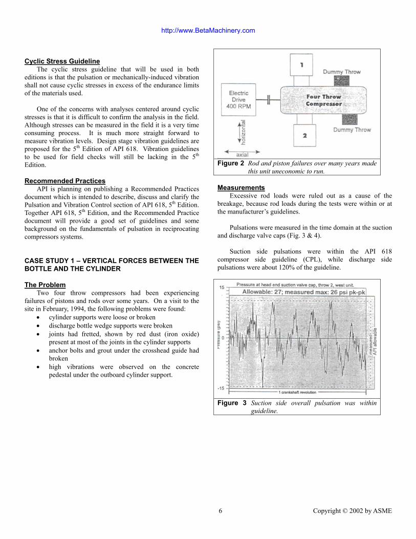
CASE STUDY 1 – VERTICAL FORCES BETWEEN THEBOTTLE AND THE CYLINDER
The ProblemTwo four throw compressors had been experiencing
failures of pistons and rods over some years. On a visit to thesite in February, 1994, the following problems were found:
• cylinder supports were loose or broken• discharge bottle wedge supports were broken• joints had fretted, shown by red dust (iron oxide)
present at most of the joints in the cylinder supports• anchor bolts and grout under the crosshead guide had
broken• high vibrations were observed on the concrete
pedestal under the outboard cylinder support.
Figure 2 Rod and piston failures over many years madethis unit uneconomic to run.
MeasurementsExcessive rod loads were ruled out as a cause of the
breakage, because rod loads during the tests were within or atthe manufacturer’s guidelines.
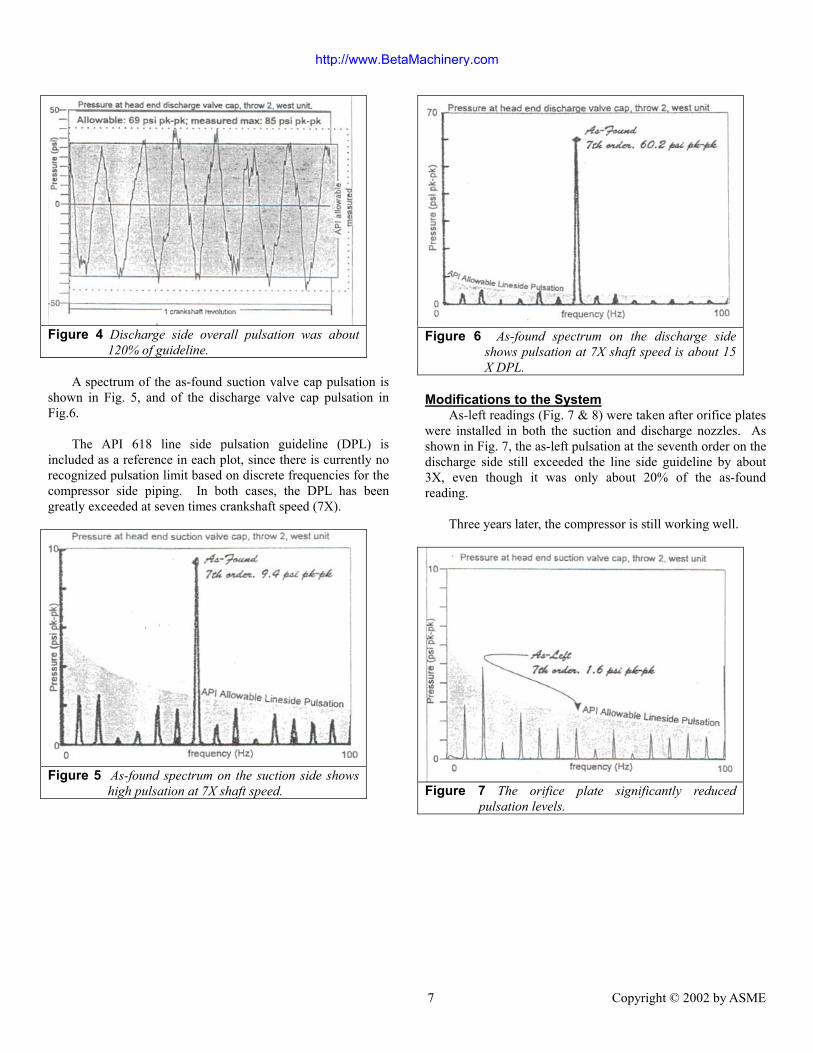
Pulsations were measured in the time domain at the suctionand discharge valve caps (Fig. 3 & 4).
Suction side pulsations were within the API 618compressor side guideline (CPL), while discharge sidepulsations were about 120% of the guideline.
Figure 3 Suction side overall pulsation was withinguideline.
http://www.BetaMachinery.com
7 Copyright © 2002 by ASME
Figure 4 Discharge side overall pulsation was about120% of guideline.
A spectrum of the as-found suction valve cap pulsation isshown in Fig. 5, and of the discharge valve cap pulsation inFig.6.
The API 618 line side pulsation guideline (DPL) isincluded as a reference in each plot, since there is currently norecognized pulsation limit based on discrete frequencies for thecompressor side piping. In both cases, the DPL has beengreatly exceeded at seven times crankshaft speed (7X).
Figure 5 As-found spectrum on the suction side showshigh pulsation at 7X shaft speed.
Figure 6 As-found spectrum on the discharge sideshows pulsation at 7X shaft speed is about 15X DPL.
Modifications to the SystemAs-left readings (Fig. 7 & 8) were taken after orifice plates
were installed in both the suction and discharge nozzles. Asshown in Fig. 7, the as-left pulsation at the seventh order on thedischarge side still exceeded the line side guideline by about3X, even though it was only about 20% of the as-foundreading.
Three years later, the compressor is still working well.
Figure 7 The orifice plate significantly reducedpulsation levels.
http://www.BetaMachinery.com

8 Copyright © 2002 by ASME
Figure 8 The orifice reduced pulsation at 7X to about20% of as-found; still three times DPL.
Vertical Forces Between Bottle and CylinderFigure 9 shows a cross-section of the suction and discharge
bottles and cylinder on one side of the machine. The standingwave pattern of the pressure pulsation carries from the valvesthrough the cylinder gas passages and the cylinder nozzle intothe bottle, on each side of the cylinder. There is no directconnection between the two standing waves, because thesuction and discharge valves are never open at the same time.
There is a difference between the amplitude and phase ofthe pulsation at different points on the standing wave.
Varying pressure acting on an area produces a varyingforce. In the vertical direction, the areas of concern are theprojected areas of the inside diameters of the suction anddischarge nozzles (Fig. 9) on the bottle and the cylinderpassages.
A computer model was used to predict pulsations, and themodel was verified with field measurements (Figs. 6 – 8). Theworst vertical forces in the discharge nozzles were calculated tobe about 7000 pounds peak to peak (pk – pk) and in the suctionnozzles about 1100 pounds pk – pk, both at the seventh order.It is clear that these forces are sufficient to cause the problemsfound.
Note that over the short length between the cylinder andthe bottle, there is very little change in pressure amplitude atlow frequencies (Fig. 10). The unbalanced force generated inshort pipe runs by pressure pulsations at low orders of runspeed (long wave lengths) will be much lower than at higherorders, all other things being equal.
Figure 9 Vertical forces due to pulsation can developbetween the cylinder and the bottle.
Consequently, the line side pulsation guideline (DPL)should not be used between the bottle and the cylinder. TheDPL would restrict low order pulsations excessively. There isno need for such restrictions. Moreover, any attempt to designa system to meet the DPL in the cylinder and nozzle would beimpractical. An unbalanced force guideline makes more sensefor this portion of the system, combined with the currentcompressor side guideline.
Figure 10 The maximum unbalanced force occurs whenpipe length equals half wave length.
http://www.BetaMachinery.com
9 Copyright © 2002 by ASME
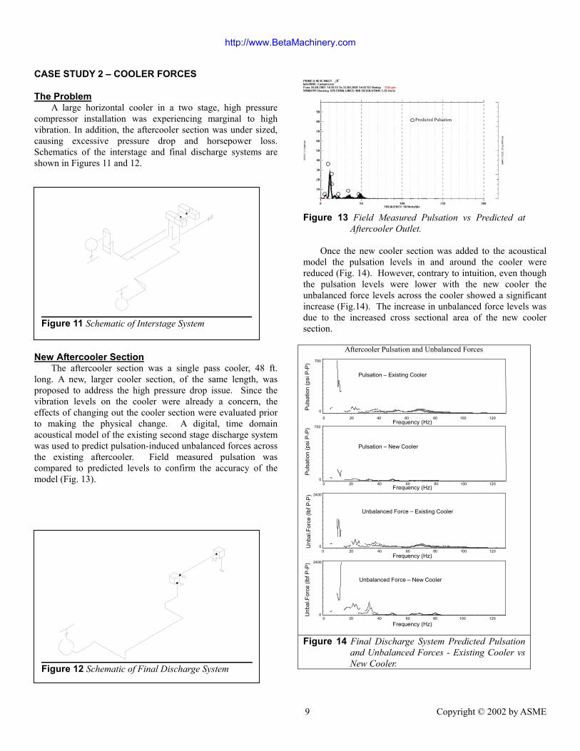
CASE STUDY 2 – COOLER FORCES
The ProblemA large horizontal cooler in a two stage, high pressure
compressor installation was experiencing marginal to highvibration. In addition, the aftercooler section was under sized,causing excessive pressure drop and horsepower loss.Schematics of the interstage and final discharge systems areshown in Figures 11 and 12.
New Aftercooler SectionThe aftercooler section was a single pass cooler, 48 ft.
long. A new, larger cooler section, of the same length, wasproposed to address the high pressure drop issue. Since thevibration levels on the cooler were already a concern, theeffects of changing out the cooler section were evaluated priorto making the physical change. A digital, time domainacoustical model of the existing second stage discharge systemwas used to predict pulsation-induced unbalanced forces acrossthe existing aftercooler. Field measured pulsation wascompared to predicted levels to confirm the accuracy of themodel (Fig. 13).
?
Predicted Pulsation
Figure 13 Field Measured Pulsation vs Predicted atAftercooler Outlet.
Once the new cooler section was added to the acousticalmodel the pulsation levels in and around the cooler werereduced (Fig. 14). However, contrary to intuition, even thoughthe pulsation levels were lower with the new cooler theunbalanced force levels across the cooler showed a significantincrease (Fig.14). The increase in unbalanced force levels wasdue to the increased cross sectional area of the new coolersection.
2400
Unb
al.F
orce
(lbf
P-P
)
Frequency (Hz)
2400
Aftercooler Pulsation and Unbalanced Forces
Unb
al.F
orce
(lbf
P-P
)
Pulsation – Existing Cooler
Frequency (Hz)
Frequency (Hz)
Pulsation – New Cooler
P
ulsa
tion
(psi
P-P
)
Puls
atio
n (p
si P
-P)
Unbalanced Force – Existing Cooler
Unbalanced Force – New Cooler
Frequency (Hz)
700
700
20 40 60 80 100 120 0
0
0 0 20 40 60 80 100 120
0 40 20 60 80 100 120
120 100 80 60 20 40 0 0
0
Figure 14 Final Discharge System Predicted Pulsationand Unbalanced Forces - Existing Cooler vsNew Cooler.Figure 12 Schematic of Final Discharge System
Figure 11 Schematic of Interstage System
http://www.BetaMachinery.com

10 Copyright © 2002 by ASME
Given the predicted increase expected in the aftercoolerunbalanced forces the cause of the cooler vibration was furtherinvestigated. It was determined that the intercooler unbalancedforces were making a significant contribution to the coolervibration. The intercooler section consisted of two passes, also48 ft. long, physically located next to the aftercooler section.Beta was asked to investigate what system changes would benecessary to lower the unbalanced forces in both the interstageand final discharge coolers as well as throughout other areas.The acoustical analysis revealed that secondary volumes wererequired to significantly reduce the pulsation and unbalancedforces. Less aggressive modifications were successful inlowering pulsation and unbalanced force levels in select areas.
Intercooler Pulsation and Unbalanced Forces
Frequency (Hz) 60 40 20 0 80 100 120
0
1800
Cooler Unbalanced Force – 2nd Volume Solution
Cooler Unbalanced Force – Existing System
U
nbal
. For
ce (l
bf P
-P)
Unb
al. F
orce
(lbf
P-P
) 1800
0 0 20 40 60 80 100 120
Frequency (Hz)
Frequency (Hz) 20 0 40 60 80 100 120
Pulsation – 2nd Volume Solution
0
150
Pul
satio
n (p
si P
-P)
Pul
satio
n (p
si P
-P)
0 20 40 60 80 100 120 0
150
Pulsation – Existing System
Frequency (Hz)
Figure 15 Interstage System Predicted Pulsation andUnbalanced Forces - Existing vs SecondaryVolume
The secondary volume solution for the interstagesignificantly lowered pulsation levels throughout the system(Fig. 15), and unbalanced force most everywhere. Againcontrary to intuition, the intercooler unbalanced forcesremained basically unchanged (Fig. 15). In this case therelative difference in pulsation levels between the cooler headervolumes remained about the same, even though the absolutelevels where much lower with the secondary volume installed.Modifications to the recycle line were required to significantlylower the intercooler unbalanced forces.
Coolers are being used more often in pipeline installationsto increase the mass of gas being pumped into the mainpipeline. Coolers are just one area where it is very important toevaluate unbalanced forces, not just pulsations, whendetermining if pulsation control is sufficient.
CONCLUSIONReciprocating compressors have a definite place in the
pipeline industry. For installations where reciprocatingmachinery are the best fit for the compression required, thedesign of the installation should be no more difficult than for asimilar centrifugal installation.
The area of pulsation and vibration control is one areawhere there is a significant difference in design requirementsbetween centrifugal and reciprocating compressors. Forreciprocating compressor installations API 618, 4th Edition,provides a good starting point for outlining design guidelines.Many of the areas that can be viewed as deficient in the 4th
Edition of API 618 (e.g. lack of unbalanced force guidelinesand vagueness in pressure drop guideline) are addressed in theproposed 5th Edition. In addition the Recommended Practicedocument API is planning on publishing around the same timeas the 5th Edition of API 618, will provide even better guidanceto any industry using reciprocating compressors.
ACKNOWLEDGMENTSThe authors wish to thank Beta Machinery Analysis Ltd.
for its support and Beta’s staff members for their assistance inproviding information for this paper.
REFERENCESReciprocating Compressors for Petroleum, Chemical, and
Gas Industry Services. API Standard 618, Fourth Edition, June1995 American Petroleum Institute, 1220 L Street, Northwest,Washington, D.C. 20005.
http://www.BetaMachinery.com