Guidelines for Sinkhole and Subsidence Rehabilitation ...
53
Guidelines for Sinkhole and Subsidence Rehabilitation based on Generic Geological Models of a Dolomite Environment on the East Rand, South Africa Ilse KLEINHANS 1,2 , J. Louis VAN ROOY 2 1 VGIconsult Projects, P.O. Box 604, Fourways, 2055, South Africa +27 (012) 991 0890 [email protected] / [email protected] *Corresponding author 2 Department of Geology, University of Pretoria, Private Bag X20, Hatfield, 0028, Pretoria, South Africa +27 (0)12 420 2023 [email protected] Highlights: • Characterization of sinkholes and subsidence environments in terms of depth to dolomite bedrock. • Overview of generally successful rehabilitation techniques for the South Africa karst environment. • Depiction of the geological models relating to the typical karst conditions in which different sinkholes develop. • Relating the geological model to the rehabilitation approach. Abstract: A sound understanding of the various factors influencing and associated with the formation of sinkholes or subsidences on dolomite land is essential for the selection of appropriate rehabilitation methods. The investigation and rehabilitation of numerous sinkholes and subsidences located on dolomite in the East Rand of South Africa, created an opportunity to develop a 1
Transcript of Guidelines for Sinkhole and Subsidence Rehabilitation ...

Guidelines for Sinkhole and Subsidence Rehabilitation based on Generic
Geological Models of a Dolomite Environment on the East Rand, South
Africa
Ilse KLEINHANS1,2, J. Louis VAN ROOY2
1VGIconsult Projects, P.O. Box 604, Fourways, 2055, South Africa
+27 (012) 991 0890
[email protected] / [email protected]
*Corresponding author
2Department of Geology, University of Pretoria, Private Bag X20, Hatfield, 0028, Pretoria, South
Africa
+27 (0)12 420 2023
Highlights: • Characterization of sinkholes and subsidence environments in terms of depth to dolomite bedrock. • Overview of generally successful rehabilitation techniques for the South Africa karst environment. • Depiction of the geological models relating to the typical karst conditions in which different sinkholes develop. • Relating the geological model to the rehabilitation approach.
Abstract: A sound understanding of the various factors influencing and
associated with the formation of sinkholes or subsidences on dolomite land is
essential for the selection of appropriate rehabilitation methods. The
investigation and rehabilitation of numerous sinkholes and subsidences located
on dolomite in the East Rand of South Africa, created an opportunity to develop a
1

broad based understanding of different karst environments, their susceptibility
to sinkhole and subsidence formation and best practice rehabilitation methods.
This paper is based on the guidelines developed whereby the geological model of
the sinkhole or subsidence is used to recommend an appropriate rehabilitation
method. Nine typical geological models with recommended rehabilitation
methods are presented in this paper.
Keywords: karst; dolomite; sinkhole; subsidence; geological model;
rehabilitation method.
1. Introduction
Engineering problems related to karst features, including sinkholes and
subsidences, on carbonate (limestone and dolomite) and evaporite (gypsum and
salt) rocks is common all over the world, including the United States of America,
United Kingdom, Europe, Asia and Africa and have been documented by various
authors (Buttrick et al., 2001 and 2011; Waltham et al., 2005; Ford and Williams,
2007; Zhou and Beck, 2011; Galve et al., 2012; Gutierrez et al., 2014 and Parise et
al., 2015).
A sinkhole is defined as a feature that occurs suddenly and manifests as a hole in
the ground that is typically circular in plan. In international literature the term
sinkhole is often synonymous with doline (SANS 1936, 2012). A subsidence is
defined as a shallow enclosed depression that occurs slowly over time and may
typically be circular, oval or linear in plan (SANS 1936, 2012).
2

The formation of sinkholes have negative social and financial implications in the
affected and immediately surrounding areas, resulting in the relocation of entire
communities to safer ground, severe damage to infrastructure or even loss of
human life (Waltham et al., 2005; Buttrick et al., 2011). On the Far West Rand of
South Africa, sinkholes induced by the dewatering of dolomite groundwater
compartments for gold mining caused the loss of life of 38 people (De Bruyn and
Bell, 2001). A community of approximately 30 000 households was relocated to
safer ground in a dolomite area west of Johannesburg, South Africa, at a cost
exceeding US $600 million (Buttrick et al., 2011). In Calatayud (Spain), underlain
by evaporites, and Allentown (Pennsylvania, USA), underlain by cavernous
limestone, sinkhole events have caused the demolition of multi-storey buildings
with direct economic losses in excess of US $6.3 million and US $8 million,
respectively (Dougherty, 2005; Gutierrez et al., 2008). Parise and Lollino (2011)
reports on the impact of natural and man-made limestone caves on
infrastructure in the Apulia region, southern Italy. The impact of subsidences in
the city of Tuzla (Bosnia and Hertzegovina) related to the extraction of salt
deposits by solution mining is reported by Mancini et al. (2009). Guerrero et al.
(2008) present a review on detrimental effects caused by sinkholes on railways
and Galve et al. (2012) and Villard et al. (2000) reports on the impact of
sinkholes on roads in Spain and France.
It is essential that the various influencing factors associated with the formation
of sinkholes and subsidences on carbonate bedrock are understood to allow for
the selection of appropriate rehabilitation methods. The main objectives when
investigating sinkholes and subsidences are to determine the cause as well as the
3

extent of subsurface erosion, the impact on existing infrastructure and the
appropriate rehabilitation methodology to improve subsurface conditions,
prevent further instability and render the area safe for future development.
The specific method of investigation and subsequent rehabilitation actions are
usually determined by the accessibility of a site. Accessibility constraints within
a built-up area, including existing infrastructure, may lead to investigation and
rehabilitation methods that differ from those generally preferred in unrestricted
areas. The goal is to obtain as much subsurface information as possible to
develop a 3-Dimensional model of the subsurface conditions that need
improvement.
Karst terrain susceptibility and hazard mapping is one of the mitigating
measures that has evolved in countries such as the USA, England, Spain, Italy,
Belgium and South Africa (Waltham et al., 2005; Gutierrez et al., 2014). The most
important step in sinkhole hazard analysis, once the sinkholes and areas affected
have been mapped and characterised by means of surface and subsurface
investigation methods, is the construction of a comprehensive cartographic
sinkhole inventory (Gutierrez et al., 2014). Sinkhole databases should include
information on: precise location of the limits of the sinkholes and underlying
subsidence structures, morphometric parameters, genetic type (sinkhole or
subsidence mechanisms and material affected), chronology, activity and
relationship with conditioning and triggering factors (Gutierrez et al., 2014).
4

Parise and Lollino (2011) and Parise (2015) for example, developed numerical
analyses for the implementation of 2- and 3-Dimensional stability models using
the finite element method for geological settings represented by continuous soft
rock mass, and the distinct element method for jointed rock masses (highly
stratified limestone) to evaluate the susceptibility to sinkhole development
related to cave systems, anthropogenic features (underground quarries) and
natural occurrences, in southern Italy.
Instability features are largely anthropogenic (i.e. caused by human activities)
and have a detrimental impact on infrastructure with potential for loss of life.
Hence poor maintenance of wet services, poor management of surface water
run-off, poorly backfilled service trenches, lack of monitoring and control of the
original groundwater level in the dolomite profile and ground vibrations (e.g.
heavy machinery, passing trains or blasting) have the potential to trigger events
(Buttrick and Van Schalkwyk, 1998). Natural and human-induced static and
dynamic loadings e,g, load imposed by heavy vehicles, drilling rigs, dumped
material and engineered structures, may trigger the collapse of pre-existing
cavities under marginal conditions, (Gutierrez et al., 2014). These conditions
may cause the mobilization of the overlying in situ materials into voids located
within or above bedrock, leading to the formation of sinkholes or subsidences
and damage to infrastructure (Kleinhans and Van Rooy, 2014).
The rehabilitation of sinkholes and subsidences is affected by a number of
aspects, such as available funding, existing and future land use, geological factors
and the depth to the groundwater level (Kleinhans and Van Rooy, 2014).
5

In South Africa, the investigation and rehabilitation of these features prior to the
1970’s were undertaken by trial and error as there were no guidelines. The
assessment of surface stability on dolomite land was formulated by Buttrick
(1992) and Buttrick et al. (2001 and 2011) with the development of the so-called
“Method of Scenario Supposition”.
The investigation and rehabilitation of numerous sinkholes and subsidences on
dolomite bedrock occurring in the East Rand of the Gauteng Province, South
Africa, made it possible to develop an understanding of the different dolomite
karst environments, their susceptibility to sinkhole and subsidence development
and best practice rehabilitation methods. Generic geological models and most
appropriate rehabilitation methods were developed to serve as a guideline for
sinkhole and subsidence rehabilitation that may also be applicable in other
carbonate rock regions affected by sinkholes and subsidences. The East Rand
covers the eastern part of the Gauteng Province in South Africa and
approximately 50% of the area is underlain by dolomite bedrock within sixty
metres from ground surface, also referred to as “dolomite land” (SANS 1936,
2012).
In the Gauteng Province, the dolomite of the Malmani Subgroup, Chuniespoort
Group, Transvaal Supergroup is notorious for sinkhole and subsidence formation
and is subdivided into the Oaktree, Monte Christo, Lyttleton and Eccles
Formations, which are differentiated based on their chert content, stromatolite
morphology, intercalated shales and erosion surfaces (Buttrick and Van
Schalkwyk, 1998). The Monte Christo and Eccles Formations are generally rich in
6

chert and the Oaktree and Lyttleton Formations contain chert-poor dolomite
(Buttrick and Van Schalkwyk, 1998). According to Button (1973) and Eriksson
and Truswell (1974), the dolomite rocks of the Malmani Subgroup are
approximately 2200 to 2300 Ma years old.
2. Evaluation of Sinkholes and Subsidences to determine
Rehabilitation Method
A number of factors need to be established after the occurrence of a surface
instability event to be able to develop the geological model. One of the most
important factors influencing the rehabilitation approach is the depth below
surface to which rehabilitation is required.
2.1. Depth of Impact
For rehabilitation purposes sinkholes or subsidences can be evaluated according
to the same influencing factors grouped under a specific depth of impact:
Shallow depth: Impact extending to a maximum depth of 8 m.
Intermediate depth: Impact extending to a maximum depth of 15 m.
Great depth: Impact extending to a depth of more than 15 m.
The depth of impact refers to the depth to which the subsurface profile is
anticipated to have been influenced during the development of a sinkhole or
subsidence. For a shallow depth of impact (maximum 8 m), the throat of the
sinkhole or lower limit of subsidence is reachable by an excavator if all other
7

influencing factors allow the use of such large and heavy equipment. For an
intermediate depth of impact (maximum 15 m), various rehabilitation
procedures or a combination of procedures may be considered and will depend
on the geological model and external influencing factors such as accessibility for
rehabilitation equipment and the impact on existing infrastructure. For a great
depth of impact (more than 15 m), the base of the sinkhole can only be reached
by means of drilling.
Zhou and Beck (2008) divide sinkholes into shallow and deep sinkholes for
mitigation purposes. Shallow sinkholes are, according to them, those that are no
more than 10 m deep, and their bases are reached by a regular backhoe. Deep
sinkholes are more than 10 m deep, and drilling rigs are needed to reach their
bases (Zhou and Beck, 2008).
2.2. Factors determining rehabilitation method
For each of the aforementioned depths of impact, the following influencing
factors are taken into consideration to determine the most appropriate
rehabilitation method or combination of methods.
2.2.1. Cause of Sinkhole or Subsidence Formation
Sinkhole or subsidence formation in South African karst is typically evaluated
from an ingress of water and groundwater level drawdown perspective (Buttrick
et al., 2001 and 2011).
8

Ingress of water: The infiltration of water is the most common cause of
sinkhole or subsidence formation in urban areas and is mostly related to
leaking or broken wet services.
Groundwater level drawdown: Dewatering of dolomite groundwater
compartments is associated with the over-utilisation of groundwater for
agricultural purposes or dewatering related to mining activities.
The mechanism of sinkhole and subsidence formation from an ingress of water
and groundwater level drawdown perspective is described in detail by Jennings
et al. (1965) and Brink (1979).
2.2.2. Complexity of the Geological Model
Over geological time, dolomite rock is dissolved and removed as bicarbonates of
calcium and magnesium by weakly acidic rainwater and percolating
groundwater (Buttrick and Van Schalkwyk, 1998). This process is facilitated by
fault, fracture and joint networks and results in typical karst features, including
interconnected cavities within the dolomite bedrock and a very irregular
bedrock surface (Buttrick and Van Schalkwyk, 1998). Younger sediments,
intrusives or residual materials (weathering products of dolomite and chert)
commonly cover the karst landscape in South Africa and these materials are
referred to as the dolomitic overburden or blanketing layer (Buttrick et al.,
2011). Hard, fresh dolomite rock is overlain by slightly weathered jointed
bedrock (epikarst) with a sudden transition to totally weathered and low-
strength, insoluble residual material consisting mainly of a low density, fine
9

grained, black to blue-grey clayey silt or silty clay rich in silica and manganese
oxides (referred to as “wad” in South African nomenclature), chert or a mixture
of wad and chert rubble (collapsed remnants of the chert interbeds) and iron
oxides that reflect the original insoluble matrix structure (Buttrick and Van
Schalkwyk, 1998). Residual dolomitic soils are commonly very porous, erodible
and compressible. These properties are due to leaching and gap grading between
wad and chert rubble (Buttrick and Van Schalkwyk, 1998). Due to natural
compaction and ferruginization near the ground surface, dolomite profiles are
typically characterised by poorer geotechnical characteristics with depth
(Buttrick and Van Schalkwyk, 1998) where the uppermost part of the soil
horizon is often of higher density and strength and relatively impervious
compared to the deeper horizoins.
The simplicity or complexity of the geological model depends on the following:
Blanketing layer:
o Composition and thickness of the blanketing layer: The mobilization
potential increases where low density material (dolomite
residuum) and especially thick horizons of dolomite residuum
(wad) are present in the profile, and voids (or disseminated
receptacles) that may be able to accommodate mobilized material
from overlying horizons are present.
o Presence of vertical or sub-vertical intrusives or shale directly in
contact with dolomite residuum (wad or ferroan soils): Typically
intrusive or shale is regarded as material with a low mobilization
potential adding stability to the blanketing layer. However, the
10

contact zone between these materials of low mobilization potential
and the dolomite residuum may in areas act as a contributing
factor to the formation of a sinkhole or a subsidence. These contact
zones may act as preferential pathways for mobilized material into
voids or cavities at depth.
o Presence of faults or fracture zones: Depending on the nature of the
faults or fracture zones present, these may act as preferential
pathways or conduits to voids below.
o Roof capping material over a void or cavity: The geological profile is
regarded as complex from a rehabilitation perspective where
dolomite residuum (wad) is overlain by a horizon of competent
chert, with subsurface erosion having taken place within the
dolomite residuum (wad) creating a void or disseminated voids
(receptacles) below the competent chert horizon.
o Geotechnical characteristics of material in the blanketing layer: The
grading, density and permeability of horizons in the blanketing
layer also play a vital role, as soil types comprising silty and clayey
material with a low permeability will have a higher resistance to
subsurface erosion, whilst sandy and gravelly soils with a high
permeability and typical low density may be more susceptible to
subsurface erosion.
o Presence of a paleo instability feature: A paleo-sinkhole or
subsidence may present an area of high susceptibility for re-
activation.
Dolomite bedrock depth and morphology:
11

o The depth to dolomite bedrock influences the maximum potential
size (diameters and depth). Small to medium size sinkholes or all
size subsidences are typically associated with dolomite bedrock at
shallow to intermediate depths (< 15 m) and medium to very large
size sinkholes or subsidences are associated with deep dolomite
bedrock (> 15 m).
o The karst landscape associated with the weathering processes of
dolomite can create variable bedrock morphologies, ranging from
simple to very complex, depending on the stage of karst
development (i.e. juvenile, youthful, mature, complex or extreme
(Waltham and Fookes, 2003)) and the presence of faults, fractures
and intrusions.
A simple geological model is typically associated with
juvenile karst (Waltham and Fookes, 2003) where the
dolomite bedrock is gently undulating to nearly horizontal,
with a homogeneous overlying blanketing layer.
A very complex geological model, according to Brink
(1979), comprises of pinnacled dolomite bedrock at
variable depths over a short lateral distance, the presence
of geological structures and a heterogeneous blanketing
layer typically comprising of dolomite residuum (wad),
grykes (deeply weathered joint or ‘solution enlarged joint’ )
typically filled with dolomite residuum (wad) and voids,
solution cavities within dolomite bedrock and remnants of
12

the original dolomite bedrock present as floaters in the
blanketing layer.
Depth or position of the groundwater level in the dolomite profile:
o The depth or position of the groundwater level in the dolomite
profile, especially in the blanketing layer, plays a significant role in
determining the susceptibility of the blanketing material to
subsurface erosion into voids or cavities to create a sinkhole.
o A subsidence may also develop if the downward migration of water
through the dolomite residuum causes a densification (compaction)
of the low density dolomite residuum.
o If the groundwater level is located above material with a high
mobilization potential, a sinkhole or a subsidence will not occur, but
sudden drawdown of the groundwater may expose low density
materials or voids and deeper lying cavities within bedrock that
may lead to the development of a sinkhole or subsidence.
The data needed for the compilation of the 3D geological model is generally
gathered from geophysical surveys, specifically gravity surveys, followed by
drilling of percussion boreholes, placed on gravity anomalies. The geophysical
surveys are useful to indicate possible subsurface structures (e.g. cavities, voids,
dykes, faults or geological contacts). In the South African karst environment the
gravity method is regarded as the most successful geophysical method to
determine dolomite bedrock topography and the thickness and density of
overburden material (Kleywegt and Pike, 1982). The drilling of rotary
percussion boreholes is regarded as one of the most reliable methods to obtain
13
point data when assessing the extent of subsurface erosion related to sinkholes
and subsidences, depth to dolomite bedrock, composition of the blanketing layer
and the depth to the groundwater level (Brink, 1979). At sites with restricted
access the Dynamic Probe Super Heavy (DPSH) Test Method can be used to
determine the consistencies of the various soil horizons and to determine if
cavities or shallow bedrock are present. In a shallow dolomite environment
(bedrock within 8 m) an excavator can be used to expose subsurface conditions.
On limestones in the United States and in Europe geophysical methods including
Ground Penetration Radar (GPR), Electrical Resistivity (ER) and Seismic
Refraction (SR) tests are commonly used to map the rock surface, determine
subsurface characteristics and locate subsurface cavities (Kannan, 1997 and
Gutierrez et al., 2014). Due to the particular composition of the overburden on
South African karst these geophysical methods are not very successful in
delineating voids in the overburden or cavities within bedrock.
2.2.3. Depth and lateral extent of instability feature, triggering mechanism and impact on existing infrastructure
Depth and extent of instability feature: The manifestation of a sinkhole or
subsidence at ground surface does not always define the depth and lateral extent
of instability. The receptacle at depth, that accommodated the eroded material,
may not be directly below the area of visual impact on surface, but can be located
at distances more than 20 m from the sinkhole or subsidence. The evaluation of
an event should therefore consider covering a surface area of between 20 m to
50 m around the sinkhole or subsidence area to ensure the instability feature has
been thoroughly investigated.
14

Depth and extent of triggering mechanism (ingress of water): The first priority
when dealing with a sinkhole or subsidence is to reduce or remove the cause or
triggering mechanism and to reduce the likelihood of aggravating the problem
(i.e. increase in sinkhole or subsidence size). In a built-up environment the
triggering mechanism is typically related to ingress of water (e.g. leaking
subsurface wet services or surface water ponding). The position of the point of
ingress in the profile in relation to the instability feature may give a preliminary
indication of the extent of the affected area to be investigated as well as the
origin of the sinkhole or subsidence.
All affected wet services need to be replaced during the sinkhole or subsidence
rehabilitation process. It is therefore critical that the depth and extent of the
affected subsurface wet service and subsurface erosion is known prior to
commencement of rehabilitation.
Impact on existing infrastructure: The position of the sinkhole or subsidence and
damaged subsurface wet service in relation to the position of existing
infrastructure plays a vital role in the rehabilitation procedures to be followed.
Infrastructure such as buildings, roads, overhead cables, subsurface services (for
example gas pipes, water mains, electrical cables) that cannot be demolished,
shut down or rerouted during the rehabilitation process need to be considered
when the rehabilitation methodology is decided upon.
15

Existing infrastructure can sometimes prevent a detailed investigation of the
sinkhole or subsidence due to access constraints and can lead to the area of
impact being inadequately or incorrectly determined. This may lead to follow-up
phases of rehabilitation of instability features such as erosion tunnels, cavities
and voids discovered during the rehabilitation process.
Where it is economically feasible, structures should be demolished, the area
properly investigated, rehabilitated and only strategic structures then rebuilt,
with appropriate precautionary measures.
Existing infrastructure may also limit investigation and rehabilitation of the
instability feature and subsurface extent which may lead to an incomplete
geological model and inappropriate rehabilitation.
2.2.4. Proposed land use after rehabilitation
The proposed land use post-rehabilitation also influence the choice of
rehabilitation method. Usually the same land use is required after rehabilitation
but in areas where the cost implications are excessive and a potential for re-
occurrence exists, consideration should be given to the sterilization of the land.
In areas where infrastructure has been affected by a sinkhole or subsidence,
demolition and rebuilding are critical and the rehabilitation must produce
subsurface conditions suitable for the specific land-use.
16
3. Sinkhole and Subsidence Rehabilitation Methods
The Department of Public Works document PW344 (2010) lists various methods
of sinkhole and subsidence rehabilitation used in South Africa and these methods
are also incorporated in the South African National Standard on sinkhole
rehabilitation (SANS 2001-BE3, 2012).
The specific method, or combination of methods, used to rehabilitate sinkholes
or subsidences depends on: a) the land-use after rehabilitation, b) available
funding, c) the subsurface conditions (or geological model), d) accessibility for
rehabilitation equipment and e) the impact of the rehabilitation procedure on
existing infrastructure (Zhou and Beck, 2008, Kleinhans, 2013).
The objectives of sinkhole or subsidence rehabilitation are to:
Expose and choke the throat of a sinkhole, remove highly compressible
and erodible dolomite residuum (wad) and replace with competent
materials creating an engineered earth mattress; OR
compact subsurface materials by the drop of a large weight; OR
backfill cavities at depth with an appropriate grout mixture.
17
Typical rehabilitation methods are described below:
3.1. Inverted Filter Method
The Inverted Filter Method comprises the backfilling of a sinkhole including
blocking of the throat of the sinkhole with rockfill and/or boulders in
combination with soilcrete (sandy gravel – G6 or G7 according to COLTO (1998) -
with 3% to 5% cement and water) or the use of self-compacting concrete. The
blocking of the throat is followed by layers of progressively finer material
ranging from cobble to sand size, compacted at a specific compaction effort to
create an impermeable capping. Some of the finer layers are sometimes also
stabilized with 3% to 5% cement. A schematic presentation of the Inverted Filter
Method is illustrated in Figure 1.
Excavation and throat plugging is according to Zhou and Beck (2008) the
simplest way to remediate an existing sinkhole. They suggest a plug of rock or
stones, concrete blocks or grout of 1.5 times the width of the throat. If the
sinkhole does not have an obvious throat, but consists of many discrete
fractures, these fractures can be blocked by dental infill grout, where the pockets
are filled with high/low slump flowable fill to plug and cap the fractures (Zhou
and Beck, 2008).
18
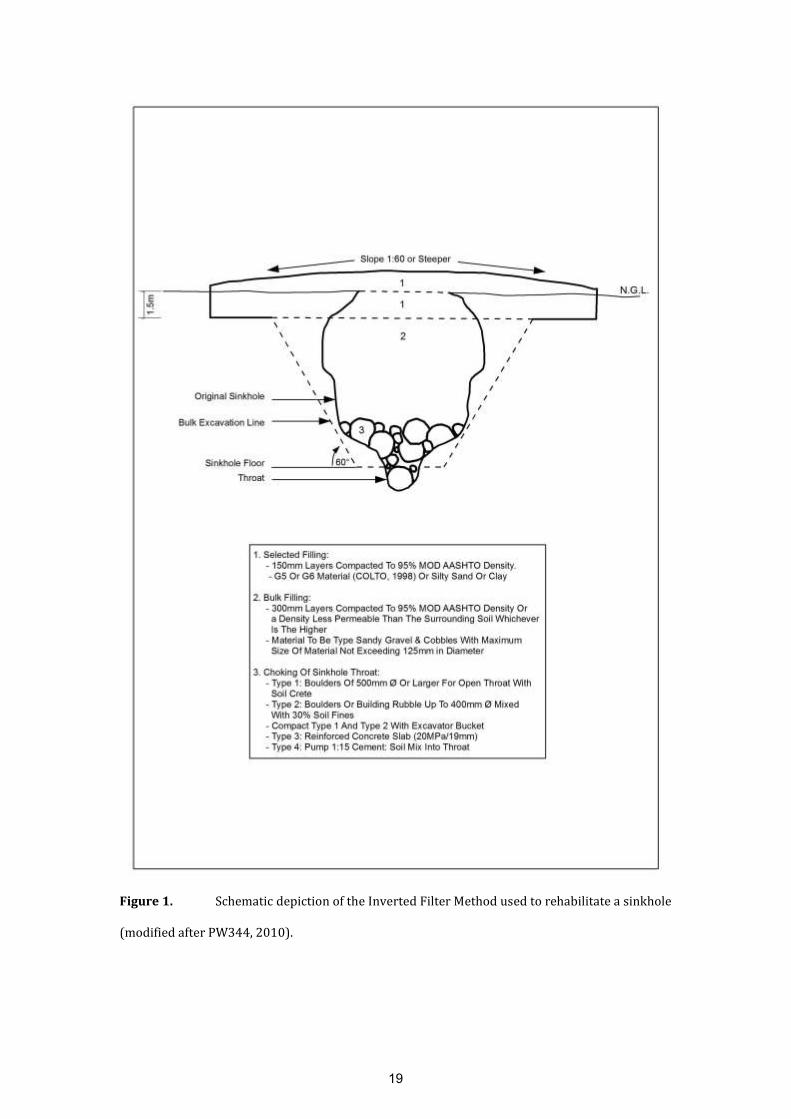
Figure 1. Schematic depiction of the Inverted Filter Method used to rehabilitate a sinkhole
(modified after PW344, 2010).
19

The Inverted Filter Method is typically applied to:
Sinkholes of small (< 2 m diameter) or medium-size (2 m - 5 m diameter).
Subsidences off all sizes (< 2 m - > 15 m diameter).
Sinkholes or subsidences with depths < 8 m (or throat of sinkhole is
visible within 8 m from natural ground surface).
Events where existing infrastructure is located at a distance, outside the
area proposed for bulk excavation.
Shallow sinkholes within 10 m from natural ground surface (Zhou and
Beck, 2008).
Geotextiles (geosynthetic reinforcement or geogrids) or mesh reinforcement
(geogrids or weldmesh) are sometimes used to retain the material above the
throat of the sinkhole or as support layers within the lower and top selected fill
layers or to line the base and walls of the sinkhole (Zhou and Beck, 2008). It
should however be noted that the use of geotextiles do not constitute a complete
repair of a new or existing sinkhole (Villard et al., 2000). A geogrid can only
serve as a temporary warning mechanism (Waltham et al., 2005). Geogrids may
be used beneficially to improve load distribution on softer overburden material
left in place on shallow overburden strata (Zhou and Beck, 2008). Geosynthetics
are generally cheaper than other measures (e.g. reinforced concrete slabs) when
used as a prevention measure in roads and railways in areas prone to sinkhole
formation, they are able to span small cavities, maintaining the serviceability of
the road during the lifetime of the project and for large cavities they temporarily
prevent the formation of catastrophic sinkholes and accidents, serving as a
warning system (Galve et al., 2012). Galve et al. (2012) and Gutierrez et al.
20

(2014) report on the development and evaluation of sinkhole susceptibility
models to optimize the application of geosynthetics to roads. The most cost-
effective geosynthetic design solution identified by means of the cost-benefit
analyses involves the installation of geogrids able to span cavities 3 m to 4 m in
diameter distributed along 55% of the high risk road sections (Galve et al.,
2012).
3.2. Dynamic Compaction Method (DC)
The DC Method involves placing of selected backfill materials typically in lifts of
2 m (can vary between 1 -3 m), followed by dropping a large weight from a
considerable height onto the material to be compacted (PW344, 2010). This is
done on a set grid, including primary and secondary points carried out for each
lift (or layer). The grid spacing for the primary DC-points for each layer varies
typically between 5 x 5 m or 7.5 x 7.5 m and secondary DC points are positioned
midway between the primary DC points. Compaction of the deepest layer is
achieved with the primary phase and compaction of the intermediate layers by
the secondary phases (Byrne et al., 1995). The final ironing compaction phase of
the upper 2 to 4 metres ensures overlapping phases by compacting the shallow
layers between the initial prints (Byrne et al., 1995). The process is started with
DC Probing to drive material (typically rockfill) into the throat of the sinkhole
with a penetration pounder until visual refusal is reached thereby chocking the
sinkhole throat. The depth of compaction is a function of the weight and shape of
the pounder and the drop height (Byrne et al., 1995). In addition, the degree of
compaction achievable also depends on the characteristics of the backfill
21
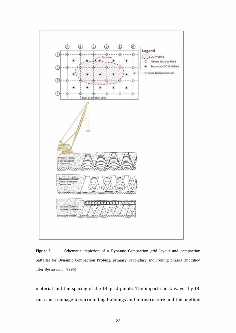
Figure 2. Schematic depiction of a Dynamic Compaction grid layout and compaction
patterns for Dynamic Compaction Probing, primary, secondary and ironing phases (modified
after Byrne et. al., 1995).
material and the spacing of the DC grid points. The impact shock waves by DC
can cause damage to surrounding buildings and infrastructure and this method
22

can only be applied where sufficient distance to neighbouring structures exists.
A schematic presentation of the Dynamic Compaction Method used to
rehabilitate a sinkhole is illustrated in Figure 2.
The Dynamic Compaction (DC) Method is applied to:
Increase the density and bearing capacity of materials when certain
subsurface constraints render other methods inappropriate.
Compact and densify poor subsurface dolomite residuum (wad) or soil
layers with a loose consistency to a maximum depth of 10 m.
Collapse the roof of a cavity located at a depth greater than the bulk
excavated area (typically to a depth of 4 m to 6 m). This will reduce the
cost of excavating to a great depth.
Collapse subsurface voids within the overburden (Zhou and Beck, 2011).
The pattern of ground deformation developed during dynamic
compaction often indicates many areas of active and potential sinkhole
development (Zhou and Beck, 2011).
Where the subsurface conditions in the area of the sinkhole presents a
safety hazard to workers, the choking of the sinkhole throat by means of
the DC Probing Method can create a safe platform to work from.
The DC Method is regarded as a cost effective and practical rehabilitation
method to densify material to a maximum depth of approximately 8 m to 10 m
below natural ground surface (Blom, 2014). Byrne et al. (1995) specifies a
maximum depth of 12 m. However, where a competent layer of chert, comprising
mainly of gravel and cobbles is present between natural ground surface and the
23

compressible layer (wad), most of the energy expended by the compaction effort
is absorbed by the competent chert layer and the material below it is not
compacted (De Bruyn and Bell, 2001). To reach the required compaction effort
down to a specific depth, the competent layer needs to be removed.
Vibro-compaction methods are not suitable to the South African karst due to the
high silt and clay content of the overburden soils and the possible initiation or
reactivation of subsurface erosion and potential sinkholes.
3.3. Compaction Grouting
Compaction grouting was originally developed in California in the United States
during the 1940’s to compact beneath and level homes (Brill and Hussin, 1993).
In the early 1980’s, compaction grouting was first used to treat sinkholes in
central Florida, United States (Brill and Hussin, 1993). This method entails the
pumping of a mix of sand, cement and water (thick grout) under a specific
pressure, down a predrilled borehole, into cavities at depth to fill voids or to
densify poor subsurface soils. During the planning phase of a grouting
programme on dolomite, for cost estimate purposes, the following grout
pressures are typically specified: 0.1 MPa in soil overburden; for highly
weathered rock 0.5 MPa and for hard rock 1.0 MPa. The thick grout forms an
enlarged bulb or series of bulbs in the soil and displaces the soil immediately
surrounding the bulb, thereby increasing its density (Byrne et al., 1995). Based
on research done on grouting of the dolomites of the Far West Rand, South
Africa, Swart (1991) notes that bulbs can be anything up to a metre and even
24
more in diameter and densification occurs within a radius of 0.3 m to 3.7 m
around the bulb. However, with compaction grouting, it is generally only possible
to obtain an average density of about 90% Modified AASHTO (Byrne et al., 1995).
There are no clearly defined design guidelines for compaction grouting but the
design phase generally forms part of the grouting process and comprises
monitoring of the degree of improvement being achieved and adapting the
grouting process as required (Byrne et al., 1995). In a dolomite environment,
unforeseen conditions, not identified during the site investigation, such as the
presence and extent of cavities will have a major influence on the volume of
grout needed.
Compaction grouting is usually planned as a series of primary and secondary
points on a grid with grid centres typically in the 1.0 m to 4.0 m range but 1.5 m
to 2.0 m is more common (Byrne et al, 1995). When compaction near surface is
required, the points have to be positioned at the closer spacing (Byrne et al,
1995). The primary points are first drilled and grouted, typically positioned 3 m
apart, followed by the secondary points, midway between the primary points,
some days later. A tertiary stage may sometimes be necessary. A schematic
representation of a grouting grid comprising primary, secondary and tertiary
grouting points to rehabilitate a sinkhole is illustrated in Figure 3.
25

Figure 3. Schematic depiction of a grouting grid comprising primary, secondary and
tertiary grouting points to rehabilitate a sinkhole.
26

Distinction is made between, upstage, downstage and a combination of
downstage and upstage grouting methods. Upstage grouting is undertaken from
the bottom of a predrilled borehole, grout is injected via 1.0 m to 2.0 m long
stages up to the length of the borehole, raising the grout tube to the top of the
next stage on completion of each grout injection (SANS 2001-BE3, 2012).
Downstage grouting is used when the borehole collapses during drilling,
preventing the drilling of the borehole to the required depth in a single operation
(SANS 2001-BE3, 2012). The hole is then advanced in 1.0 m to 2.0 m stages that
are grouted and the grout allowed to set for at least 24 hours. The hole is then re-
drilled and advanced to the depth of the next stage. Combined Downstage and
Upstage Grouting is considered where the blanketing layer covering a cavity is
thin and a stable working environment needs to be created first by downstage
grouting, followed by upstage grouting of the balance of the stratum (Byrne et al.,
1995).
The Grouting Method is applicable under the following conditions:
The method is relatively expensive and is considered where subsurface
conditions exist at depths that cannot be treated by means of the Inverted
Filter Method or the DC Method.
To fillvoids above bedrock or cavities within bedrock.
Improving subsurface conditions to variable depths ranging from ground
surface to more than 60 m.
Improving subsurface conditions close to or below existing structures.
Densification of compressible dolomite residuum (wad) or loose soils.
27
Zhou and Beck (2008) describes the use of jet grouting where the filling of a
sinkhole throat is too stiff to displace with high pressure. This process involves
pumping a fluid grout into the soil with a rotating high-pressure jet which erodes
soil and cuts stiff clays and soft erodible rock into gravel to small boulder-sized
pieces. Pressures of 30 – 50 MPa are typically used and the large soil particles,
including sand and gravel in the sinkhole filling, mix with the grout to produce a
mixed-in-place concrete. This is however not a preferred method used on
dolomite, as the grout under high pressure may cause further subsurface erosion
of the dolomite residuum forming additional cavities at depth.
Cap grouting is recommended when a sinkhole is associated with small but
discrete fractures on the bedrock surface and the area to be treated is extensive
(Zhou and Beck, 2008). Cap grouting uses low pressure (140 kPa or less) to
pump lean cement to cover the sinkhole base, fill voids, plug fissures, and
displace soft soil (Zhou and Beck, 2008). This cement cover provides support to
the upper layers and prevents further vertical groundwater percolation (Zhou
and Beck, 2008). Grout hole spacing is typically 0.9 m (Zhou and Beck, 2008).
Slurry grouting may also be used to fill cavities at virtually any depth that can be
drilled (Zhou and Beck, 2008). This method involves the injection of various
mixtures of very fluid grouts into the ground. It can run along the plane of
weakness in the limestone and overburden forming very effective seals; with
little to no densification of overburden soil taking place (Zhou and Beck, 2008).
Milanovic (2000) recommends large cavities to be filled with rock fills and grout
through shafts or large diameter boreholes.
28

3.4. Combination of Inverted Filter and Dynamic Compaction Method
A combination of the Dynamic Compaction and Inverted Filter Method is
applicable for the following conditions:
Collapsing of cavities at depth and the chocking of the sinkhole throat by
means of the Dynamic Compaction Probing Method up to a specific depth
(typically to a depth of 6 m below ground surface), followed by the
Inverted Filter Method
Where an area comprises of sub-areas with sinkholes or underlying
deeper voids in the blanketing material are not reachable with an
excavator or zones of dolomite residuum (wad) are present in profile to a
depth of 10 m.
This is a cost effective and practical rehabilitation method to improve subsurface
conditions in areas affected by sinkholes to a maximum depth of between 10 m
and 15 m below natural ground level.
3.5. Combination of Inverted Filter Method and Compaction Grouting
A combination of these two methods may be considered in areas where the
sinkhole or subsidence at depth is interconnected with sub-vertical erosion
tunnels extending into dolomite bedrock over a distance away from the
manifestation at surface of the sinkhole or subsidence. The Inverted Filter
Method can be applied to a maximum depth of 12 m. The bulk excavation area
will be shaped in a funnel in the area where the sub-vertical erosion tunnel
29

extending into dolomite rock before the Inverted Filter Method commences.
After completion of the Inverted Filter Method a grouting programme is
undertaken in the area where the sub-vertical erosion tunnel was encountered in
the bulk excavated area. The purpose of the grouting programme is to seal off the
sub-vertical erosion tunnels extending into dolomite bedrock by means of a
grout curtain, or if sufficient funds are available also to fill the cavity.
3.6. Combination of Dynamic Compaction Method and Compaction Grouting
A combination of these two methods may be considered in areas of major traffic,
such as landing strips, roads and railway lines, where a sinkhole occurred and
cavernous conditions exist at a depth greater than 10 m. As specified by Byrne et
al. (1995) only a 90% compaction effort is typically obtained with compaction
grouting. Major roads and railway lines require subsurface layers compacted to
at least 95% of Modified AASHTO compaction effort. Therefore compaction
grouting can be carried out to fill cavities at depth and Dynamic Compaction
conducted to create an engineered earth mattress providing the required
bearing capacity.
3.7. Self-Compacting Concrete or Soil-Cement Mix
Self-compacting concrete comprises of a pumpable concrete mix that requires no
external vibration to achieve consolidation, with a 28 day cube strength greater
than 5 MPa (SANS 2001-BE3, 2012). For sinkhole rehabilitation a strength of
10 MPa is typically specified.
30

Soil-cement mix comprises a high slump mix of soil and cementitious binder with
a 28 day cube strength greater than 2 MPa (SANS 2001-BE3, 2012).
Self-compacting concrete or soil-cement mix is used to choke the throat of a
sinkhole, plug grykes, or forming a stable working platform at the base of a
sinkhole, or for mass filling of cavities or runnels (SANS 2001-BE3, 2012).
3.8. Chemical Grouting
Permeation chemical grouting comprises a completely fluid mixture of
chemicals [http:/www.earthtech.net/residential/sinkhole-repair/
services/chemical-grouting]. It forms a stone-like material by injecting
polyurethane based grout along a sleeve port pipe into the subsurface
under pressure along a pre-drilled hole. The chemical grout material
permeates the soil and solidifies to increase the strength of the stratum
and its load bearing characteristics. This method is especially effective in
shallow soils and is the typically method used in Florida (USA) to fill
sinkhole voids and densifying loose soils that exist within 5 m of the
surface.
Expansive Chemical Grouting involves the injection of expansive foam
that fills voids and re-levels foundations. One such method is the URETEK
Deep Injection Process [http:/uretekicr.com/2013/02/06deep-injection-
for-sinkholes]. The expanding geo-polymere is placed exactly at the soil
strata depth where soil compaction and densification are needed. The
31

URETEK geo-polymere is injected in the holes (created by a Dynamic
Cone Penetrometer (DCP) or DPSH), using a controlled, low-impact
process. Multiple injections at varying depths create columns of vertical
support. This ‘top down’ injection method is often used on shallow
injection applications as it strengthens the upper layer of soil to help
contain the pressure of the lower levels of compaction. Once injected, the
geo-polymere material expands up to 15 times the material’s liquid
volume and strengthens to 90% within 30 minutes. This rapid expansion
results in compaction. Through this non-destructive process, soil
compaction and densification occurs and void areas are filled and fully
stabilized. This method is applicable for the rehabilitation of small to
medium size sinkholes located within a depth of 5 metres below ground
surface.
4. Appropriate rehabilitation method based on the geological model
and influencing factors
The investigation and rehabilitation of numerous sinkholes and subsidences on
the East Rand, Gauteng Province, made it possible to develop an understanding
of the different dolomite environments, their susceptibility to sinkhole and
subsidence formation and best practise rehabilitation methods. Generic
geological models were developed and are linked to most appropriate
rehabilitation methods to serve as a guideline for sinkhole and subsidence
rehabilitation in karst environments.
32

A total of seventeen generic geological models, representative of sinkholes and
subsidences on the East Rand were developed, but only nine are presented in
this paper with recommended rehabilitation methods.
The sinkhole or subsidence rehabilitation method should not be prescriptive,
given the vast number of variables involved. Each sinkhole or subsidence is
unique and a site specific set of criteria for the rehabilitation of these features
should be developed to ensure proper stabilisation and safe future use of the
area. The basic principles that need to be followed in all instances are listed
below (Kleinhans and Van Rooy, 2014):
Ensuring that the cause of the sinkhole or subsidence has been identified
and removed;
The position and extent of the receptacles have been determined and
erosion paths sealed;
The eroded area and possible voids properly densified or backfilled;
A proper impervious blanket is created;
Ensuring that all subsurface wet services comply with industry standards;
Ensuring that proper surface drainage exists.
A comprehensive understanding of the affected area is essential for selecting
cost effective and practical rehabilitation measures (Kleinhans and Van Rooy,
2014). It is therefore as a rule, necessary to perform a thorough site investigation
of the feature as well as the surrounding affected area. Rehabilitation of only a
portion of the affected area will in most instances lead to propagation of the
problem (feature) to adjacent areas (Kleinhans and Van Rooy, 2014).
33

The groundwater in all nine models presented is located below bedrock level and
therefore renders the entire unconsolidated profile overlying dolomite bedrock
prone to mobilization.
4.1. Impact to a maximum depth of 8 m
Three geological models (Model 1 – 3) and the most appropriate rehabilitation
method for each model are illustrated in Figure 4 and described in the legend
(Table 1).
Table 1. Generic Geological and Rehabilitation Legend for Figure 4, 5 and 6.
34

Figure 4. Generic Geological and Rehabilitation Model 1 to 3.
35

The various influencing factors considered to determine the most appropriate
rehabilitation method for each of the three models are given in Table 2 below.
Table 2. Influencing Factors considered for Generic Geological and Recommended
Rehabilitation Models 1 to 3.
Influencing
Factors
Model 1 Model 2 Model 3
Cause/ trigger Broken 110 mm diameter uPVC
midblock sewer pipe at 2 m
depth, point source.
Multiple cracks and disconnected
160 mm diameter uPVC sewer line.
At 4 m depth, 20 m section of pipe
malfunctioning.
Ponding and infiltration of run-off
surface water. Large surface area
affected.
Geological
Model
Complexity
Simple, homogeneous, nearly
horizontal profile.
Intermediate to complex, highly
variable bedrock profile.
Complex, highly variable bedrock
profile and material susceptible to
subsurface erosion.
Blanketing
Layer
Chert and dolomite residuum. No
voids.
Colluvium, chert and dolomite
residuum (wad) with dolomite
floaters. Voids encountered.
Colluvium, chert residuum in sub-
areas, dolomite residuum (wad).
Voids encountered.
Bedrock Shallow at 3 m, with 1 m grykes
and smaller extending to 8 m. No
cavities encountered, but
possibility of voids in grykes.
Pinnacle dolomite bedrock from a
depth of 1 m to 8 m, adjoining v-
shaped grykes. Cavities present.
Highly jointed vertically and
horizontally, joints filled with
dolomite residuum (wad).
Interconnected cavities
encountered. Dolomite bedrock at
8 m to 9 m.
Instability
Feature
dimensions
2 m diameter size sinkhole
extending to 2 m depth.
4 m diameter size sinkhole extending
to 4 m depth.
4 m diameter size sinkhole
extending to 3 m depth, 2 m
diameter sinkhole extending to 2 m
and 4 m diameter size subsidence
extending to 1 m depth.
Impact on
Infrastructure
Houses on both sides of sinkhole,
4 m away.
Sinkhole located in sewer servitude
and road.
Electrical infrastructure located less
than 10 m from affected area.
Rehabilitation
Method(s)
Inverted Filter Method. Inverted Filter Method. Compaction Grouting Programme.
Land Use
after
Rehabilitation
Garden areas of residential
stands, wet service servitude.
Road, sewer servitude and garden
area of residential stands.
Open field in close proximity to
electrical infrastructure.
36
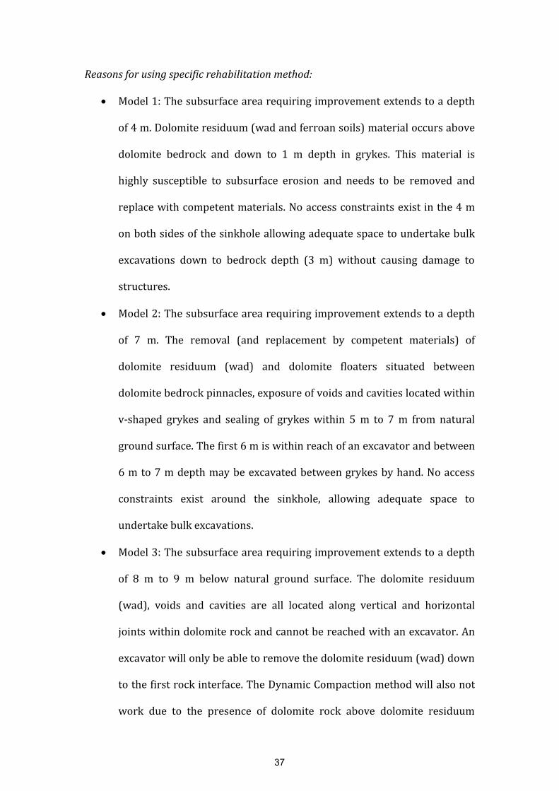
Reasons for using specific rehabilitation method:
Model 1: The subsurface area requiring improvement extends to a depth
of 4 m. Dolomite residuum (wad and ferroan soils) material occurs above
dolomite bedrock and down to 1 m depth in grykes. This material is
highly susceptible to subsurface erosion and needs to be removed and
replace with competent materials. No access constraints exist in the 4 m
on both sides of the sinkhole allowing adequate space to undertake bulk
excavations down to bedrock depth (3 m) without causing damage to
structures.
Model 2: The subsurface area requiring improvement extends to a depth
of 7 m. The removal (and replacement by competent materials) of
dolomite residuum (wad) and dolomite floaters situated between
dolomite bedrock pinnacles, exposure of voids and cavities located within
v-shaped grykes and sealing of grykes within 5 m to 7 m from natural
ground surface. The first 6 m is within reach of an excavator and between
6 m to 7 m depth may be excavated between grykes by hand. No access
constraints exist around the sinkhole, allowing adequate space to
undertake bulk excavations.
Model 3: The subsurface area requiring improvement extends to a depth
of 8 m to 9 m below natural ground surface. The dolomite residuum
(wad), voids and cavities are all located along vertical and horizontal
joints within dolomite rock and cannot be reached with an excavator. An
excavator will only be able to remove the dolomite residuum (wad) down
to the first rock interface. The Dynamic Compaction method will also not
work due to the presence of dolomite rock above dolomite residuum
37

(wad). The best practical solution to rehabilitate the features and improve
the poor subsurface conditions is to fill the sinkholes and subsidence with
boulders and soilcrete up to ground surface and then perform a grouting
programme. The purpose of the grouting programme will be to densify
dolomite residuum (wad) and fill voids and cavities, to ensure the
integrity of electrical infrastructure. There are no access constraints for
this rehabilitation method.
4.2. Impact to a maximum depth of 15 m
Three geological models (Models 4 – 6) and the most appropriate rehabilitation
method for each are illustrated in Figure 5 and described in the related legend
(Table 1).
38

Figure 5. Generic Geological and Rehabilitation Model 4 to 6.
39
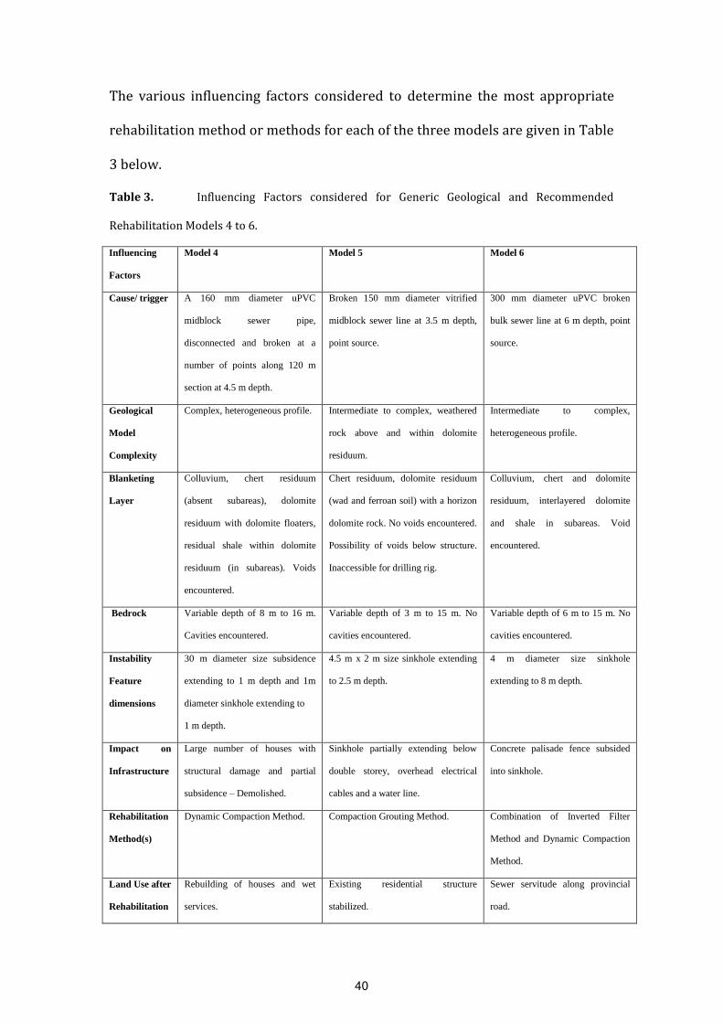
The various influencing factors considered to determine the most appropriate
rehabilitation method or methods for each of the three models are given in Table
3 below.
Table 3. Influencing Factors considered for Generic Geological and Recommended
Rehabilitation Models 4 to 6.
Influencing
Factors
Model 4 Model 5 Model 6
Cause/ trigger A 160 mm diameter uPVC
midblock sewer pipe,
disconnected and broken at a
number of points along 120 m
section at 4.5 m depth.
Broken 150 mm diameter vitrified
midblock sewer line at 3.5 m depth,
point source.
300 mm diameter uPVC broken
bulk sewer line at 6 m depth, point
source.
Geological
Model
Complexity
Complex, heterogeneous profile. Intermediate to complex, weathered
rock above and within dolomite
residuum.
Intermediate to complex,
heterogeneous profile.
Blanketing
Layer
Colluvium, chert residuum
(absent subareas), dolomite
residuum with dolomite floaters,
residual shale within dolomite
residuum (in subareas). Voids
encountered.
Chert residuum, dolomite residuum
(wad and ferroan soil) with a horizon
dolomite rock. No voids encountered.
Possibility of voids below structure.
Inaccessible for drilling rig.
Colluvium, chert and dolomite
residuum, interlayered dolomite
and shale in subareas. Void
encountered.
Bedrock Variable depth of 8 m to 16 m.
Cavities encountered.
Variable depth of 3 m to 15 m. No
cavities encountered.
Variable depth of 6 m to 15 m. No
cavities encountered.
Instability
Feature
dimensions
30 m diameter size subsidence
extending to 1 m depth and 1m
diameter sinkhole extending to
1 m depth.
4.5 m x 2 m size sinkhole extending
to 2.5 m depth.
4 m diameter size sinkhole
extending to 8 m depth.
Impact on
Infrastructure
Large number of houses with
structural damage and partial
subsidence – Demolished.
Sinkhole partially extending below
double storey, overhead electrical
cables and a water line.
Concrete palisade fence subsided
into sinkhole.
Rehabilitation
Method(s)
Dynamic Compaction Method. Compaction Grouting Method. Combination of Inverted Filter
Method and Dynamic Compaction
Method.
Land Use after
Rehabilitation
Rebuilding of houses and wet
services.
Existing residential structure
stabilized.
Sewer servitude along provincial
road.
40

Reasons for using specific rehabilitation method:
Model 4: The subsurface area requiring improvement extends to a depth
of 15 m and consists of a thick horizon of dolomite residuum, a number of
voids and cavities. As the area is proposed for the rebuilding of houses, it
was necessary to remove the problematic dolomite residuum material,
voids and cavities, and create an engineered earth mattress of between 4
m to 14 m with the Dynamic Compaction Method. The roof over the void
was collapsed by means of the Dynamic Probing Method. No access
constraints exist, due to all houses being demolished before
rehabilitation.
Model 5: The subsurface area requiring improvement extends to a depth
of 15 m and is partially located below a structure. The Inverted Filter
Method is typically used to a maximum depth of 8 m and is therefore not a
suitable solution. The Dynamic Compaction Method is also not suitable
due to the sinkhole partially being located below the structure. The
recommended rehabilitation method is the Compaction Grouting Method,
as this method can be used to fill voids or cavities below the residential
structure and to densify the low density compressible dolomite residuum
down to bedrock depth at 15 m. Before the Compaction Grouting
Programme commenced the sinkhole was backfilled with 10 MPa mass
concrete below the structure and the remaining open portion was
backfilled with soilcrete. Access constraints exist due to the residential
structure and overhead electrical cables.
Model 6: The subsurface area requiring improvement extends to a depth
of 14 m; comprising of a thick horizon of dolomite residuum (wad), a void
41

and possible cavity at depth with a sewer line located at 6 m below
ground surface. Excavation was therefore required to a depth of 6 m
below ground surface to replace the wet service with HDPE pipes. The
area of the void and sinkhole was over-excavated to a depth of 10 m. The
Dynamic Compaction Probing Method was used to choke the over-
excavated sinkhole area up to 6 m below ground surface, followed by
backfilling according to the Inverted Filter Method of rehabilitation up to
ground level.
4.3. Impact to a depth of more than 15 m
Three geological models and the most appropriate rehabilitation method for
each are illustrated in Figure 6 and described in the related legend in Table 1.
42

Figure 6. Generic Geological and Rehabilitation Model 7 to 9.
43
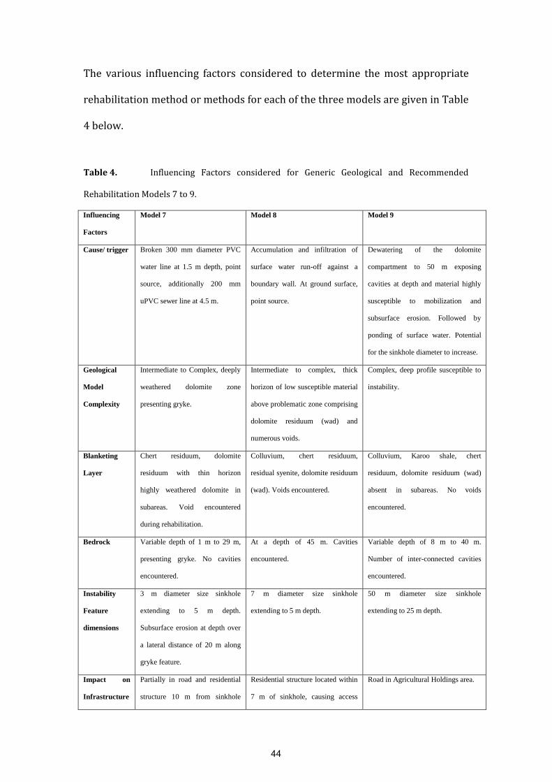
The various influencing factors considered to determine the most appropriate
rehabilitation method or methods for each of the three models are given in Table
4 below.
Table 4. Influencing Factors considered for Generic Geological and Recommended
Rehabilitation Models 7 to 9.
Influencing
Factors
Model 7 Model 8 Model 9
Cause/ trigger Broken 300 mm diameter PVC
water line at 1.5 m depth, point
source, additionally 200 mm
uPVC sewer line at 4.5 m.
Accumulation and infiltration of
surface water run-off against a
boundary wall. At ground surface,
point source.
Dewatering of the dolomite
compartment to 50 m exposing
cavities at depth and material highly
susceptible to mobilization and
subsurface erosion. Followed by
ponding of surface water. Potential
for the sinkhole diameter to increase.
Geological
Model
Complexity
Intermediate to Complex, deeply
weathered dolomite zone
presenting gryke.
Intermediate to complex, thick
horizon of low susceptible material
above problematic zone comprising
dolomite residuum (wad) and
numerous voids.
Complex, deep profile susceptible to
instability.
Blanketing
Layer
Chert residuum, dolomite
residuum with thin horizon
highly weathered dolomite in
subareas. Void encountered
during rehabilitation.
Colluvium, chert residuum,
residual syenite, dolomite residuum
(wad). Voids encountered.
Colluvium, Karoo shale, chert
residuum, dolomite residuum (wad)
absent in subareas. No voids
encountered.
Bedrock Variable depth of 1 m to 29 m,
presenting gryke. No cavities
encountered.
At a depth of 45 m. Cavities
encountered.
Variable depth of 8 m to 40 m.
Number of inter-connected cavities
encountered.
Instability
Feature
dimensions
3 m diameter size sinkhole
extending to 5 m depth.
Subsurface erosion at depth over
a lateral distance of 20 m along
gryke feature.
7 m diameter size sinkhole
extending to 5 m depth.
50 m diameter size sinkhole
extending to 25 m depth.
Impact on
Infrastructure
Partially in road and residential
structure 10 m from sinkhole
Residential structure located within
7 m of sinkhole, causing access
Road in Agricultural Holdings area.
44

severely cracked with one
portion slightly subsided.
Residential structure partially
located over gryke caused access
constraints.
constraints and need to be
demolished.
Rehabilitation
Method(s)
Compaction Grouting and
Inverted Filter Method.
Compaction Grouting Method
including a grout curtain. Or a
capping layer of low permeability
material with sterilization of the
stand with the residential structure.
Sterilization of land.
Land Use
after
Rehabilitation
Existing residential structure
stabilized.
Open field and sterilization of stand
with residential structure.
Agricultural.
Reasons for using specific rehabilitation method:
Model 7: The subsurface area requiring improvement extends to a depth
of 29 m, including a deep gryke (deep narrow slot) filled with dolomite
residuum (wad) and possibly also voids; extending below the residential
structure located 10 m away. The Compaction Grouting method is
applicable to fill voids or cavities at depth in the area between the
sinkhole and structure and below the structure, and to densify the low
density compressible dolomite residuum down to bedrock depth at 29 m,
to stabilize the conditions below the existing house and surroundings.
The Inverted Filter Method is utilised to improve soil conditions within
the area of the sinkhole. A section of wet services needed to be replaced,
together with a portion of the road.
Model 8: The recommended rehabilitation method is a grouting
programme, including the creation of a grout curtain around the area
proposed for improvement. As the dolomite residuum (wad) comprises a
45

large number of voids and dolomite bedrock with cavities from a depth of
approximately 35 m below ground surface, receptacles can readily accept
mobilized material (including low susceptible materials) from above. The
cost implications related to such a grouting programme will amount to
more than 3 million US dollars and consequently is not regarded as a
feasible option, considering the current land use (open field with one
residential structure affected by the sinkhole). The alternative and more
feasible option is to re-locate the residence and demolish the structure on
the stand adjacent to the sinkhole and properly fence off the affected area
including the evacuated stand. A capping layer of bulk unconsolidated low
permeability material is then constructed to at least 1.5 m above natural
ground level and extending at least 10 m beyond the sinkhole footprint
area.. The surrounding area is landscaped to promote good surface water
drainage away from the unconsolidated filled sinkhole.
Model 9: Sterilization of the land is recommended with the placing of a
soil berm around the sinkhole area and landscaping of the immediate
surrounding areas to ensure effective surface water run-off away from the
sinkhole. It will be necessary to fence off the affected area to prevent
uncontrolled access. The rehabilitation of instability features of this
extent is costly (including backfilling with boulders and soilcrete with
finer layers closer to ground surface) and not economically viable,
especially when located on agricultural land. The long term rehabilitation
measure for instability features caused by dewatering is the proper
management and control of groundwater in dolomite compartments by
ensuring that groundwater levels are restored to their original level,
46

thereby creating stability. Consideration can only be given to the
rehabilitation of existing instability features after the groundwater level
has been restored to its original or near original level, if such feature
poses a risk to existing structures of importance.
5. Conclusions
Based on the nine generic geological and rehabilitation models presented for the
East Rand it is evident that each sinkhole or subsidence is to a large extent
unique, and a large number of influencing factors need to be considered when
selecting the most appropriate rehabilitation method.
Rehabilitation methods vary and the method used will depend largely on
available funding and the locality of the instability feature, specifically in terms of
the current and proposed land use after rehabilitation. The method and
materials required to rehabilitate a sinkhole in an undeveloped rural area will be
vastly different from that needed to repair a sinkhole or a subsidence below an
occupied building or road in a highly urbanized area.
The rehabilitation of sinkholes and subsidences can be evaluated according to
the same influencing factors grouped under a specific depth of impact. From a
practical point of view distinction is made between impact depths of shallower
than 8 m, between 8 m and 15 m and deeper than 15 m.
47

Influencing factors to be considered for the rehabilitation of all sinkholes and
subsidences, include: a) cause/trigger mechanics of sinkhole or subsidence
formation; b) complexity of the geological model; c) depth and lateral extent of
instability; d) impact on existing infrastructure and e) current and proposed
land-use after rehabilitation.
The rehabilitation in all these instances should however have the same end goal
to ensure eroded zones and possible voids and cavities are properly backfilled
and poor materials such as dolomite residuum (wad) are densified or replaced to
create an engineered earth mattress. All affected wet services must be replaced
to comply with industry standards and the surface drainage must be away from
the area and all proposed or existing structures or infrastructure.
Even though each sinkhole or subsidence is unique, the evaluation of the various
influencing factors considered to determine the most appropriate rehabilitation
method are the same. The same approach is therefore suggested in other regions
affected by sinkholes and subsidences.
Similar or near similar geological scenarios may exist in other dolomite or
limestone regions and the various generic geological and rehabilitation models
developed for the East Rand may serve as a guideline on the most appropriate
rehabilitation methods in similar geological scenarios.
48
6. Acknowledgements
The authors wish to acknowledge the Ekurhuleni Metropolitan Municipality for
allowing the use of information gathered during the investigation and
rehabilitation of instability features in their area of jurisdiction. Additional
acknowledgement is extended to all parties that assisted with the project. The
valuable comments and suggestions received from the reviewers are also
appreciated.
7. Bibliography
Blom, E., 2014. Personal communication: Makarios Geotechnical Contractors.
Brill, G.T., Hussin, J.D., 1993. The use of compaction grouting to remediate a
railroad embankment in a karst environment, in: Beck, B.F. (Ed.), Applied
Karst Geology. Balkema, Rotterdam, pp. 259-264.
Brink, A.B.A., 1979. Engineering Geology of Southern Africa. Volume 1: The
first 2 000 million years of geological time. Building Publications, Pretoria, -
319pp.
Button, A., 1973. The Strategraphic history of the Malmani dolomite in the
eastern and north-eastern Transvaal. Trans. Geol. Soc. S. Afr., 229-247.
Buttrick, D., Van Schalkwyk, A., 1998. Hazard and risk assessment for
sinkhole formation on dolomite land in South Africa. Environmental Geology,
36, 1-2, 170-178.
49

Buttrick, D.B., 1992. Characterisation and appropriate development of sites
on dolomite. Unpublished Ph. D. thesis. University of Pretoria. Pretoria.
Buttrick, D.B., Van Schalkwyk, A., Kleywecht, R., Watermeyer, R., 2001.
Proposed Method for Dolomite Land Hazard and Risk Assessment in South
Africa. Journal of the South African Institution of Civil Engineering 43 (2), 9-
14.
Buttrick, D.B., Trollip, N.Y.G., Watermeyer, R.B., Pieterse, N.D., Gerber, A.G.,
2011. A performance based approach to dolomite risk management.
Environmental Earth Sciences, 1127-1138.
Byrne, G., Everett, J.P., Schwartz, K., Friedlaender, E.A., Mackintosh, N., Wetter,
C., 1995. A Guide to Practical Geotechnical Engineering in Southern Africa,
third edition Frankipile South Africa, -356pp.
Chemical Grouting-Sinkhole Repair / Earth Tech. (Retrieved 2014). Available
on the Internet at http://www.earthtech.net/residential/sinkhole-
repair/services/chemical-grouting.
Committee of Land Transport Officials COLTO, 1998. Standard Specifications
for Road and Bridge Works (ISBN 9783218980000).
De Bruyn, I.A., Bell, F.G., 2001. The Occurrence of Sinkholes and Subsidence
Depressions in the Far West Rand and Gauteng Province, South Africa and
Their Engineering Implications. Environmental & Engineering Geoscience VII
(3), 281-295.
Department of Public Works,PW344, 2010. Appropriate Development of
Infrastructure on Dolomite. Manual for Consultants.
50

Dougherty, P., 2005. Sinkhole destruction of Corporate Plaza, Pennsylvania,
in: Waltham, T., Bell, F.G., Culshaw, M.G. (Ed.), Sinkholes and Subsidences.
Praxis Publishing Ltd., Chichester, pp. 304-308.
Eriksson, K.A., Truswell, J.F., 1974. Tidal flat associations from the lower
Proterozoic carbonate sequence in South Africa. Sedimentology 21, 293-309.
Ford, D.C., Williams, P., 2007. Karst Hydrogeology and Geomorphology, Wiley,
Chichester, -562pp.
Galve, J.P., Gutierrez, F., Guerrero, J., Alonso, J., Diego, I., 2012. Optimizing the
application of geosynthetics to roads in sinkhole-prone areas on the basis of
hazard models and cost-benefit analyses. Geotextiles and Geomembranes 34,
80-92.
Guerrero, F., Gutierrez, F., Bonachea, J., Lucha, P., 2008. A sinkhole
susceptibility zonation based on paleokarst analysis along a stretch of the
Madrid-Barcelona high-speed railway built over gypsum- and salt-bearing
evaporates (NE Spain). Engineering Geology 102, 1-2, 62-73.
Gutierrez, F., Calaforra, J.M., Cardona, F., Orti, F., Duran, J.J., Garay, P., 2008.
Geological and environmental implications of evaporate karst in Spain.
Environmental Geology 53, 951-965.
Gutierrez, F., Parise, M., De Waele, J., Jourde, H., 2014. A review on natural and
human-induced geohazards and impacts in karst. Earth Science Reviews 138,
61-88.
Jennings, J.E., Brink, A.B.A., Louw, A., Gowan, G.D., 1965. Sinkholes and
Subsidences in the Transvaal Dolomite of South Africa, in: Proc. 6th
International conference of Soil Mech. And Found. Eng., Montreal, 51-54.
51

Kannan, R.C., 1997. Designing foundations around sinkholes, in: Beck, B.F. &
Stephenson, J.B. (Ed.), The Engineering Geology and Hydrogeology of Karst
Terranes, Balkema, Rotterdam, pp. 313-318.
Kleinhans, I.,2013. Rehabilitation of sinkholes and life threatening hazards
related to dolomite. Construction Review 24 (7), 36-37.
Kleinhans, I., Van Rooy, J.L., 2014. The formation of Sinkholes or Subsidences
and related Geotechnical Models. Dolomite Seminar, University of Pretoria,
Pretoria, 98-110.
Kleywegt, R.J., Pike, D.R., 1982. Surface subsidence and sinkholes caused by
lowering of the dolomitic water table on the Far West Rand Gold Field of
South Africa. Annal of Geological Survey of South Africa 16, pp. 77-105.
Mancini, F., Stecchi, F., Zanni, M., Gabbianelli, G., 2009. Monitoring ground
subsidence induced by salt mining in the city of Tuzla (Bosnia and
Herzegovina). Engineering Geology 58, 381-389.
Milanovic, P.T., 2000. Geological Engineering in Karst. Zebra, Belgrade, -347
pp.
Parise, M., Lollino, P., 2011. A preliminary analysis of failure mechanisms in
karst and man-made underground caves in Southern Italy. Geomorphology
134, 132-143.
Parise, M., 2015. A procedure for evaluating the susceptibility to natural and
anthropogenic sinkholes. Georisk 9, 4, 272-285.
Parise, M., Closson, D., Gutierrez, F., Stevanovic, Z., 2015. Anticipating and
managing engineering problems in the complex karst environment.
Environmental Earth Sciences, DOI 10.1007 /s12665-015-4647-5.Sinkhole
52

Remediation & Repair with Deep Injection. (Retrieved 2014). Available on the
Internet at http://uretekicr.com/2013/02/06/deep-injection-for-sinkholes.
South African National Standard SANS 1936-1/2/3/4, 2012. Development of
dolomite land. Edition 1 (ISBN 978-0-626-27840-3).
South African National Standard SANS 2001-BE3, 2012. Repair of sinkholes
and subsidences in dolomite land. Edition 1 (ISBN 978-0-626-27047-6).
Swart, C.J.U., 1991. Grouting practices for the evaluation and improvement of
dolomitic sites on the Far West Rand, South Africa. Unpublished Ph. D. thesis,
University of Pretoria, Pretoria.
Villard, P., Gourc, J.P., Giraud, H., 2000. A geosynthetic reinforcement solution
to prevent the formation of localized sinkholes. Canadian Geotechnical
Journal 37, 987-999.
Waltham, A.C., Bell, F.G., Culshaw, M.G., 2005. Sinkholes and Subsidences.
Karst and Cavernous Rocks in Engineering and Construction. Praxis
Publishing Ltd., Chichester, UK. -382pp.
Waltham, A.C., Fookes, P.G., 2003. Engineering classification of karst ground
conditions. Quarterly Journal of Engineering Geology and Hydrogeology 36,
101-118.
Zhou, W., Beck, B.F., 2008. Management and mitigation of sinkholes on karst
lands: an overview of practical applications. Environ. Geol. 55, 837-851.
Zhou, W., Beck, B.F., 2011. Engineering issues on karst, in: van Beynen, P.E.
(Ed.), Karst Management. Springer, Dordrecht, pp. 9-45.
53